21
College of Agricultural Sciences Cooperative Extension Agricultural Engineering Member's Guide Unit 1 R O C K E T R Y 18 U.S.C. 707

College of Agricultural SciencesCooperative Extension
Agricultural EngineeringMember's GuideUnit 1
ROCKETRY
18 U.S.C. 707

This 4-H Rocketry ProjectMember's Guidebelongs to:
Name
Address
4-H Club
School
County
4-H Coordinator
Prepared by U. B. Bakker, associate professor, Department of Agricultural and Extension Education, in cooperation withmembers of the Department of Agricultural and Biological Engineering and the 4-H Engineering Science CurriculumCommittee.
Visit Penn State’s College of Agricultural Sciences on the Web: http://www.cas.psu.edu
Penn State College of Agricultural Sciences research, extension, and resident education programs are funded in part by Pennsylvania counties, the Commonwealth ofPennsylvania, and the U.S. Department of Agriculture.
This publication is available from the Publications Distribution Center, The Pennsylvania State University, 112 Agricultural Administration Building, University Park, PA16802. For information telephone (814) 865-6713.
Issued in furtherance of Cooperative Extension Work, Acts of Congress May 8 and June 30, 1914, in cooperation with the U.S. Department of Agriculture and thePennsylvania Legislature. T. R. Alter, Director of Cooperative Extension, The Pennsylvania State University.
This publication is available in alternative media on request.
The Pennsylvania State University is committed to the policy that all persons shall have equal access to programs, facilities, admission, and employment without regard topersonal characteristics not related to ability, performance, or qualifications as determined by University policy or by state or federal authorities. It is the policy of theUniversity to maintain an academic and work environment free of discrimination, including harassment. The Pennsylvania State University prohibits discrimination andharassment against any person because of age, ancestry, color, disability or handicap, national origin, race, religious creed, sex, sexual orientation, or veteran status.Discrimination or harassment against faculty, staff, or students will not be tolerated at The Pennsylvania State University. Direct all inquiries regarding the nondiscrimina-tion policy to the Affirmative Action Director, The Pennsylvania State University, 201 Willard Building, University Park, PA 16802-2801, Tel 814-865-4700/V, 814-863-1150/TTY.
Produced by Information and Communication Technologies in the College of Agricultural Sciences
© The Pennsylvania State University 1994
C0711A R2M10/01ps4015

4-H RocketryMember's Guide
1
Requirements for 4-H Rocketry ProjectUnit 1
Initial
1. Build from a kit one single-stage rocket (two options):a. Each club member may choose to build any single-stage model.b. Each member will build a single stage model rocket agreed upon by the
whole club. ______
2. Launch your completed rocket at least twice, once with a low power engineand once with a high power engine. ______
3. Know and follow the 4-H Model Rocketry Safety Code. ______
4. Know how to find altitude with one tracking station. ______
5. Know firing circuit operation and firing procedures. ______
6. Know rocket parts and engine structure. ______
7. Complete the quiz to be given by your leader. ______
8. Take a photograph of your rocket for inside back cover of this project book. ______
9. Complete all other parts of this book. ______
10. Exhibit your rocket and completed project book at roundup. ______
PROJECT SCORE
Category Points Possible Score
I. Quiz score 25 ______
II. Book neatness 25 ______
III. Rocketry report 25 ______
IV. Roundup exhibit 25 ______
TOTAL 100AWARD ______
Items I and II can be judged prior to Roundup by the 4-H leader or other persons soappointed.

4-H RocketryMember's Guide
2
4-H Model Rocketry Safety Code
Before you begin the project, read and understand the rocketry safety code. Following this code
means success for model rocketry.
1. I will construct my model rockets, making sure there are no substantial metal parts in the vicinity
of the rocket’s engine. I will not use metallic rocket engines.
2. In my model rockets, I will use only commercially manufactured model rocket engines. I willnot tamper with or reload these engines.
3. My model rockets will be ignited only by electrical means and at a distance of 20 feet from the
launch panel and spectators. My launch panel will contain at least one safety switch to prevent
accidental launching.
4. I will not build model rockets that weigh more than one pound (16 ounces) when loaded; and
the total propellant will not weigh more than 4 ounces, as governed by federal regulations.
5. My model rockets will employ a recovery system to slow their descent and allow a safe return
to earth. Before each launch, I will carefully inspect the recovery system to insure its safe
deployment.
6. I will always launch my model rockets from a launching rod, rail, or other suitable guide of at
least 3 feet in length and aimed no more than 30 degrees from the vertical.
7. I will check the stability of my model rocket before its first flight. I will launch my rockets only
with adult supervision.
8. I will not launch model rockets in high winds, conditions of low visibility, populated areas, areas
where they might endanger aircraft in flight, areas where they might present a fire hazard, or under
any conditions that might endanger property or persons.
9. My model rockets will not be launched as weapons against targets in the air or on the ground,
nor will they contain explosive or pyrotechnic warheads.
10. I will always act in a mature manner with safety first.

4-H RocketryMember's Guide
3
Equipment Needed to Fire and Track the Rocket
Three devices are needed to fire and track the rockets you launch. They are a launch pad/safety flag ;a control panel; and a tracking scope (Figures 1, 2, and 3). These items are for sale from leadingmodel rocket manufacturing companies, but you may prefer to build your own.
The construction plans given in this guide are very simple, yet they contain all necessary safetyprecautions. Each device can be built with more features than shown.
1. Launch Pad
The first item to construct is the launch pad/safety flag. You will need the following materials:• One launch rod at least 36 inches long and 1/8 inch in diameter. This can be bought at a hobby orhardware store.• One piece of 1-inch plywood about 1 foot square to make the base.• A piece of heavy-duty aluminum foil about 3 feet long.
Drill a 1/8-inch hole in the center of the plywood base. Cover the base with the aluminum foil. Thetop portion should have two layers of foil. To assemble, place the rod into the base and force itdown. The foil protects the base from the engine’s blast.
Figure 1. Launch Pad Safety Flag
Build this safety flag with a soda straw, a 1/2-inch piece of wooden rod that fits in the straw, apiece of brightly colored paper, cloth, or plastic, and some glue. The flag can be placed on topof the launch rod. It will alert everyone to the sharp rod and will prevent accidents.

4-H RocketryMember's Guide
4
2. Control Panel
The launch control panel is shown in Figure 2. Build or obtain a box the size of a large cigar box orlarger. It can be made of metal, wood, or strong plastic. Working with wood may be the most satis-factory.
The box will house two switches, one a doorbell button and the other a type requiring a key to openand close the circuit. The switches can be purchased at an electrical or hardware store. (A car igni-tion switch, with key, can be used for the safety switch. You may be able to get one at a used carparts place.)
Divide a 35-foot length of No. 16 double strand heavy duty extension cord into a 10-foot piece and a25-foot length. Attach battery clips to the two wires at one end of the 10-foot section. This will bethe lead from the battery to the launch control panel. The 25-foot piece of lamp cord will be the leadfrom the launch control panel to the launch pad. Fasten miniature alligator clips to the two wires onone end of this section of lamp cord.
Drill two holes in the top of the box. The size of the holes will depend on the size of the twoswitches to be mounted. Drill a second set of holes large enough to allow the extension cords to passthrough on the side of the box.
Mount the key (safety) switch and push button (firing) switch. If the box is not open on the bottom,insert the wires through the side holes (before mounting the switches) and through the top holes andfasten the wires as shown on the drawing below. Before fastening the wires, tie a knot about 10inches from the free end of both the 10-foot and the 25-foot pieces or use wire clamps to keep thecords from being pulled out. Fasten one wire of each section to one of the doorbell button terminalsand the other to the safety switch terminals. Fasten the switches securely to the box top. If the box isopen on the bottom, you may fasten the switches to the box top first and then follow the same proce-dure of attaching the wires to the terminals.
The diagram below shows the wiring procedure.
Figure 2. Schematic Drawing of Wiring for Launch Panel

4-H RocketryMember's Guide
5
3. Tracking Scope
The last item you need to construct is used to determine the height your rocket ascends. You willneed the following materials: a broom handle or similar stick, a piece of 3/4 inch white pine 2 to 4inches wide and about 12 to 16 inches long for a sighting stick, a piece of string, a fishing sinker (1/4to 1/2 ounce), a protractor, a 3/16-inch bolt (2 1/2 inches long) with wing nut, two eye-screws (3/4 to1 inch in diameter) and some brads. Use Figure 3 as a guide.
First, drill a hole through the middle of your sighting stick large enough to accommodate the wingnut bolt. Next, drill a second hole of the same size through the top of the broom stick. Place two eye-screws into opposite ends of the sighting stick so you can sight through both. To one side of thesighting stick, fasten the protractor firmly. Drive a brad (nail) halfway in at the center of the diam-eter line of the protractor. On this brad, hang the string with a weight at the other end.
Push the bolt through the hole in the broom stick and then the sighting stick and put the wing nut on.(If a camera tripod is available, you may wish to use it instead of the broom stick, but mounting itwill be slightly different.)
The launch range section of this project will tell you where to set up the tracking scope in referenceto the launching pad. Push the broom stick into the ground far enough to make the tracking scopestable.
Using this tracking scope is very simple. First, the distance between your launch pad and trackingscope when they are set up is known as the baseline—for example, 300 feet. Second, when therocket is launched, it will fly upward to its peak and arch over to return. The person or crew at thetracking station will follow the rocket through the two eye-screws to its peak and then lock thetracking scope in that position. Third, the string with the weight on it will line up with a
certain degree on the protractor. In this example, we will use 30 degrees. The tracking crew willinform the launch recorder that the reading is 30 degrees. The launch recorder will turn to the tan-gent chart in the back of this guide and find the tangent for 30 degrees, which is .58. The recorderwill then multiply .58 by 300 feet, which is the baseline, and come up with 174 feet of altitude. Thisis the approximate altitude the rocket reaches.
(Multiply Baseline by Tangent)Baseline 300 feet
(30 = .58) Tangent x .58Approx. 175.00 feet altitude
Figure 3. Tracking Scope
4-H RocketryMember's Guide
6
Building Your Model Rocket
There are many model rocket styles to choose from. Your leader can help you choose one. Most kitshave a good set of easy-to-understand instructions. Follow them.
Here are a few additional pointers:
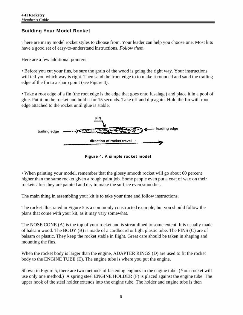
• Before you cut your fins, be sure the grain of the wood is going the right way. Your instructionswill tell you which way is right. Then sand the front edge to to make it rounded and sand the trailingedge of the fin to a sharp point (see Figure 4).
• Take a root edge of a fin (the root edge is the edge that goes onto fusalage) and place it in a pool ofglue. Put it on the rocket and hold it for 15 seconds. Take off and dip again. Hold the fin with rootedge attached to the rocket until glue is stable.
Figure 4. A simple rocket model
• When painting your model, remember that the glossy smooth rocket will go about 60 percenthigher than the same rocket given a rough paint job. Some people even put a coat of wax on theirrockets after they are painted and dry to make the surface even smoother.
The main thing in assembling your kit is to take your time and follow instructions.
The rocket illustrated in Figure 5 is a commonly constructed example, but you should follow theplans that come with your kit, as it may vary somewhat.
The NOSE CONE (A) is the top of your rocket and is streamlined to some extent. It is usually madeof balsam wood. The BODY (B) is made of a cardboard or light plastic tube. The FINS (C) are ofbalsam or plastic. They keep the rocket stable in flight. Great care should be taken in shaping andmounting the fins.
When the rocket body is larger than the engine, ADAPTER RINGS (D) are used to fit the rocketbody to the ENGINE TUBE (E). The engine tube is where you put the engine.
Shown in Figure 5, there are two methods of fastening engines in the engine tube. (Your rocket willuse only one method.) A spring steel ENGINE HOLDER (F) is placed against the engine tube. Theupper hook of the steel holder extends into the engine tube. The holder and engine tube is then
trailing edge
FIN
direction of rocket travel
leading edge

4-H RocketryMember's Guide
7
wrapped with TAPE (G). The engine can be slipped into the tube by pulling the spring steel holderback and allowing it to reset itself when the engine is inserted all the way.
The other method is just to glue an ENGINE RETAINING RING (H) inside the top of the enginetube. A few layers of tape are wrapped around the engine so that it fits snugly when inserted.
FIREPROOF WADDING (I) is used to protect the recovery system from the hot gases of the ejec-tion charge. Four-inch square sheets of fireproof crepe paper can be used.
Figure 5. A model rocket illustration
The recovery device shown is a rolled-up plastic PARACHUTE (J). SHROUD LINES (K) are tiedto the chute and to the EYE SCREW (M). Fastened to the eye screw also is the SHOCK CORD (L).The other end of the shock cord is fastened to the rocket body.
To keep the rocket stable during launch, a LAUNCH LUG (N) is used.
4-H RocketryMember's Guide
8
The Rocket Engine
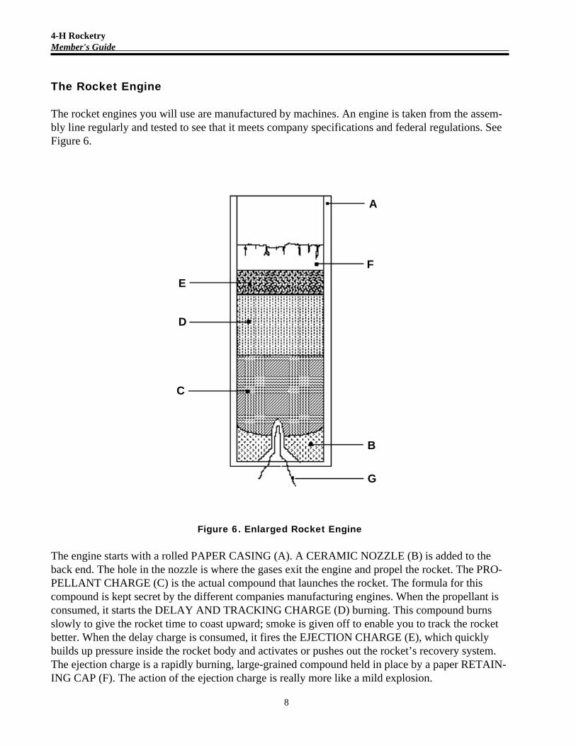
The rocket engines you will use are manufactured by machines. An engine is taken from the assem-bly line regularly and tested to see that it meets company specifications and federal regulations. SeeFigure 6.
Figure 6. Enlarged Rocket Engine
The engine starts with a rolled PAPER CASING (A). A CERAMIC NOZZLE (B) is added to theback end. The hole in the nozzle is where the gases exit the engine and propel the rocket. The PRO-PELLANT CHARGE (C) is the actual compound that launches the rocket. The formula for thiscompound is kept secret by the different companies manufacturing engines. When the propellant isconsumed, it starts the DELAY AND TRACKING CHARGE (D) burning. This compound burnsslowly to give the rocket time to coast upward; smoke is given off to enable you to track the rocketbetter. When the delay charge is consumed, it fires the EJECTION CHARGE (E), which quicklybuilds up pressure inside the rocket body and activates or pushes out the rocket’s recovery system.The ejection charge is a rapidly burning, large-grained compound held in place by a paper RETAIN-ING CAP (F). The action of the ejection charge is really more like a mild explosion.
A
F
B
G
E
D
C

4-H RocketryMember's Guide
9
All model rockets are fired electrically for safety reasons. (This also keeps them out of the fireworkscategory.) An IGNITER WIRE (G) is used and is placed into the cavity of the propellant charge asillustrated in Figure 6. (The different parts of the rocket engine illustrated can be labeled and coloredwith pencils.)
Engines have varying degrees of power and are classified A, B, C, D, E, and F. The A enginesgive you a choice of a weak 1/4 power, a stronger 1/2 power, or the full A engine. The B size ismore powerful and the F size is the most powerful.(Each letter is twice as powerful as the onebefore.) You will be concerned with engine sizes 1/4 A through C. Be sure to use the engine sug-gested for your rocket.
Figure 6a. Power “A” Type Rocket Engine
The engine in Figure 6a is an “A” power engine. What does the 8-3 mean? The first number is theaverage thrust in Newtons (a unit of measure; 4.54 Newtons equals 1 pound of force). In this casethe thrust is 8. The number after the hyphen is the time delay in seconds before the recovery systemwill be activated. In this case, it is 3 seconds. For more information on engines, read the data sheetssupplied with most engines.
Recovery Systems
Safety rules require that your rocket have a safe recovery system to prevent the rocket from descend-ing too swiftly. There are three main types of recovery methods, and all are activated by the ejectioncharge of the engine.
1. The most popular method is the parachute. Upon being ejected from the rocket, it unfolds andpermits a slow and safe descent. You will probably have to chase your rocket a bit farther with thismethod because the wind will carry it downrange.
2. The next most popular is the streamer system. The streamer is a strip of crepe paper from 1/2 to 2inches wide and up to 3 or more feet long. When ejected from the rocket, it unrolls and providesenough drag to slow the descent.
3. Another method used mainly on smaller rockets is to alter the balance, or aerodynamic design, ofthe model. This can be done in several ways. The ejection charge can blow the nose cone out and

4-H RocketryMember's Guide
10
destroy the streamlining, causing it to tumble back down slowly and safely. These two methods aretumble recovery systems.
Another way is to design the rocket so that the ejection charge will push the engine casing backtowards, but not out of, the end of the rocket, changing the balance. This will not let it fly, so again ittumbles down slowly and safely.
One more reason for recovery systems is that you will be able to reload and repack the rocket youjust recovered and launch again and again.
Launching Your RocketFins on a rocket are different in design and purpose than those on an airplane. Rockets are designedto fly vertically and not horizontally. Therefore, with your launch pad level on the ground, yourrocket will be launched straight up, which is 90 degrees. If you wish to launch at a slight angle(keeping in mind that 30 degrees from the vertical is maximum permissible) place a small blockunder one side of the launch pad.
After the engine is installed in the rocket, the recovery system can be checked and packed. Theigniter wire (see rocket engine chart) can be bent and installed deep enough into the rocket enginenozzle to be certain of ignition. To keep the igniter wire in place and to keep the igniter from short-ing out, spread the two ends and place a BB-sized piece of fireproof wadding between the wires andinto the throat of the nozzle.
The rocket can now be placed on the pad by inserting the launching rod through the launching lugand sliding the rocket down to the bottom. After connecting one clip to each end of the igniter wire,you are now ready to take command of the launching panel. You can now turn to the Launch Daysection of this unit.
Launch DayLaunch Personnel and Their Duties
RSO—The Range Safety Officer is a responsible adult, usually the club leader, in charge of theentire project.The RSO’s duty is to see that all safety procedures are followed during launch days.The RSO has the power to hold, postpone, or completely refuse to OK any rocket felt to be unsatis-factory until the fault is corrected. The RSO will call attention to the model to be launched and thename of the builder.
FC—The Flight Commander is the rocket builder and is in charge of loading and firing the rocket.(Each member in turn becomes the FC for their own rocket.) The FC has the right to call a hold inthe countdown if trouble develops. After launch and recovery, the FC moves to a new position onthe Recovery Team.
LR—The Launch Recorder is a club member who records another member’s launch. After thelaunch and recovery, the LR signs the record sheet and then assumes a new position as FC.

4-H RocketryMember's Guide
11
CD—The Communications Director is a club member who keeps the trackers and recovery crew intouch with the launch control center. The CD can call a hold in the count-down if trouble develops.In smaller clubs the LR and CD’s jobs can be handled by one member. In larger clubs they areseparate and the CD then becomes the new LR. The RSO may have the job of announcing thelaunches and their builders.
TC—The Tracking Crew can be one, two, or three club members situated where they can track theflight of a rocket, mark its angle, and report the angle to the CD at LC(Launch Control). The TC cancall a hold if they develop trouble at their station. The number one tracker (if there is more than one)moves next to CD. Number two becomes number one, three becomes two, and the new tracker isnumber three.
RT— The Recovery Team consists of the rest of the club scattered downrange to watch for andlocate the rocket launched by another member. The RT is not permitted to touch or disturb therecovered rocket unless Launch Control gives permission to do so. It is their job to be ready at alltimes. The rotation is the same as for TC.
LCC—The Launch Control Center is the area containing the RSO, the FC, the LR, the CD, if any,and the launch panel. (Can also be called Mission Control.)
When choosing and setting up your launch range, there are several things you need to consider.Use Figure 7 as a model for setting up your launch range.
First, the launch range has to be as large and as flat as possible. Size depends on the size of therocket engines being used. If everyone is using low power engines, the field size should be aboutfour or five hundred feet square. For the larger engines, you should have about a half mile square. Ifyou have the large field, you are set for both launches. Don’t forget to get permission to use the fieldfirst and don’t destroy private property. Choose a range that is easy to get to. Farms and airstrips notin use are good places to start checking.
If your launch range is limited, as most will be, you must position everyone carefully.
A weather team can be appointed to find out which direction the wind is blowing. This can be doneby cloud watching, putting a streamer on top of a very high pole, or just tossing aloft a stonewrapped in paper in the hope that as it gets up it will unwrap. The stone will come sailing back down(watch out) and the paper will float in the wind.
With the wind direction known, downwind—or the direction the wind is blowing—is downrangeand upwind is uprange.
One-fourth of the distance downrange, in the center of the workable space, is where to locate thelaunch pad. Go back uprange one-half of this distance and make a 90-degree turn left or right (de-pending on which point will be better for setting up the tracking station). Now, mark off 100 feet forsmall rocket engine launches and 300 feet or more for large engine launches. This distance will bethe baseline for finding altitudes attained by your rockets. Set your tracking scope here.

4-H RocketryMember's Guide
12
The launch control center will be about 20 feet from the pad. Set it up so the FC can follow therocket downrange.
The recovery crew is spread out at different points downrange (RT-1, RT-2, etc.). They shouldsituated where they will have unobstructed visibility.
CommunicationsA good means of communication is going to be needed between Trackers, Recovery Team, andLaunch Control Center. Walkie-talkies are recommended because of the ease in setting them up.Good walkie-talkies are expensive but might be borrowed if some members do not already havethem.
Telephones or intercoms that use wires for hookup are a second choice, if available. Remember tolay wires so members and spectators will not trip over them. Runners may be set up between sta-tions, or members can just shout from one point to another.
A Typical Good LaunchHere is a typical good launch starting right from the range.
After selecting a good field for the launching range, you must set up your launching day. Be sureyou select an alternate date in case of bad weather. If the launch is to be open to the public, informthe newspapers one or two weeks in advance.
On the scheduled day, arrive early to set up range. Those launching a rocket should be given anumber. Number one will be first to launch, number two will be the LR first and then move in turnto LC, etc. The RSO is checking safety but will assist if members get stuck.
First, a team should find the direction of the wind and move the equipment to the upwind section ofthe field, near the middle (use Figure 7 as a guide).
The pad can be set in place with the safety flag on it, and its wire run from the control panel (LCC).Run the power wire to the car battery. It would be convenient to obtain a card table or two to set upas the LCC. Decide where the LR, the FC, and the CD, if any, are to sit.
The tracker can measure off the distance into the wind from the pad and make a left or right turnacross wind for the distance decided upon. The tracking scope is set up at this point. It is advisableto set up the tracking scope so the sun is at your back as much as possible as you follow the rocket.
Mark off sections for spectators to sit. Again, try to have their backs to the sun so they can have agood view of the launches and returns.
Set up and/or check out the communications to be used for the day. Everyone can leave their work-books and launch record sheets, with the top section filled in, at the LCC.

4-H RocketryMember's Guide
13
Figure 7. Model Rocket Launch Range

4-H RocketryMember's Guide
14
The recovery team can be spread out downrange so they each have a good vantage point. The othermembers can take their positions. It’s time to begin.
The LR takes the launch record sheet that belongs to the FC and signs or initials the first space. (Thetop section has already been completed by the FC.) The LR then fills in the date of launch; engineuse; total weight, if known; angle of launch; wind speed and direction; and temperature and visibil-ity. The tracking officer can sign before or after the launch.
The LR now reports he is GO and puts a check in the proper space.
While the LR was filling in the spaces, the FC has been packing the recovery system and inspectingand installing: the engine, and the igniter wire. Then the FC reports “Rocket is GO” and the LRchecks the space.
The FC places the rocket on the pad, makes the electrical connections, and reports “Pad is GO.”
The tracking crew reports “Tracking is GO.”The recovery crew reports “Recovery is GO.”Everyone at LCC is ready, so “LC is GO.”
The “Range is GO” and the RSO gives the key to the FC. The FC inserts the key, turns the panel on,and reports “All systems GO for launch.”
The CD or RSO counts “T-minus 5-4-3-2-1-Ignition.” On ignition, the FC pushes the button and therocket soars off the pad. Being aerodynamically designed and balanced, it will arch into the windsomewhat. The LR keeps track of the “time.” The tracking station off to the side tracks and followsthe rocket all the way up to the highest point of its flight. They lock the tracking scope at that posi-tion. The recovery device deploys and the LR has already checked “Lift-off has occurred” and isnow checking “Recovery system is GO.” The recovery team keeps their eyes on the descendingrocket as the wind carries the rocket downrange closer to them. The TC (tracking crew) calls in theangle they read off the tracking scope. The LR fills in the space and converts it to the tangent. TheLR then figures out the altitude and fills in that space. The estimated duration of the flight (from lift-off to touch down) is figured and filled in. The flight performance is judged poor, fair, good, orexcellent.
The RSO initials his space and reclaims the key. After the rocket is brought back to LCC everyonerotates to the next position and makes ready for the next launch. The RSO will help everyone rotateso all get a chance at each position. Good luck.

4-H RocketryMember's Guide
15
4-H Launch Record SheetFlight commander_____________________________________________________________Rocket name or number_______________________________________Weight empty_______Rocket colors_____________________________________Recovery method______________Date completed____________________Completed dimensions__________________________
LAUNCH NUMBER No. 1 No. 2 No. 3 No. 4
Launch Recorder (LR) ________________________________________________________
Tracking Officer (T.O.)___ _____________________________________________________
Date of launch_____ _________________________________________________________
Engine used_____ __________________________________________________________ _
Total weight_____ _________________________________________________________ ___
Angle of launch_______ ________________________________________________________
Wind velocity & direction____________ __________________________________________ _
Temperature & visibility_____________________ _________________________________ __
Launch Recorder is GO__________________ _______________________________________
Rocket is GO__________________________________________________ _______________
Launch pad is GO_______________________________________ _______________________
Tracking is GO___________________________________________ ___________________ _
Recovery is GO___________________________________________ ____________________
Launch Control is GO______________________________ _____________________________
Range is GO________________________________________ __________________________
All systems GO for launch___ ____________________________________________________
T-minus 5-4-3-2-1-Ignition_______ ____________________________________________ ___
Lift-off has occurred_____ ______________________________________________________
Recovery system is GO_____________ ____________________________________________
Tracking reports (degs.)___________________________________________ _____________
Computed altitude___________________________________________________ ______ ____
Flight duration_______________________________________________________ _ ________
Flight performance_______________________________________ ____ ______ ____________
RSO initials___________________________________________________ _____ _ ________

4-H RocketryMember's Guide
16
4-H Model Rocketry QuizUnit One
Identify the parts:
1. ________________________________ 4. ____________________________________2. ________________________________ 5. ____________________________________3. ________________________________ 6. ____________________________________
Answer the following questions—Club leader will provide the questions:
7. ________________________________ _____________________________________ 8. ________________________________________________________________________ 9. ________________________________________________________________________10. ________________________________________________________________________11. ________________________________________________________________________12. ________________________________________________________________________13. ________________________________ _____________________________________
14. B4 - 2 B6 - 4 B14 - 5 B6 - 6
15. ________________________________
True or false? Club leader will provide the questions:
16. _______________________ 21. _______________________17. _______________________ 22. _______________________18. _______________________ 23. _______________________19. _______________________ 24. _______________________20. _______________________ 25. _______________________
Possible score is 25 points. Points achieved in this quiz: ____________

4-H RocketryMember's Guide
17
My 4-H Rocketry Project Report
Write a brief summary of what you learned from this project. Describe any particular problems thatyou encountered and how you solved them. What does 4-H model rocketry mean to you?

4-H RocketryMember's Guide
18
Angles and Tangents
Angle Tangent Angle Tangent Angle Tangent Angle Tangent
1 .02 23 .42 45 1.00 67 2.362 .03 24 .45 46 1.04 68 2.483 .05 25 .47 47 1.07 69 2.614 .07 26 .49 48 1.11 70 2.755 .09 27 .51 49 1.15 71 2.906 .11 28 .53 50 1.19 72 3.087 .12 29 .55 51 1.23 73 3.278 .14 30 .58 52 1.28 74 3.499 .16 31 .60 53 1.33 75 3.73
10 .18 32 .62 54 1.38 76 4.0111 .19 33 .65 55 1.43 77 4.3312 .21 34 .67 56 1.48 78 4.7013 .23 35 .70 57 1.54 79 5.1414 .25 36 .73 58 1.60 80 5.6715 .27 37 .75 59 1.66 81 6.3116 .29 38 .78 60 1.73 82 7.1217 .31 39 .81 61 1.80 83 8.1418 .32 40 .84 62 1.88 84 9.5119 .34 41 .87 63 1.96 85 11.4320 .36 42 .90 64 2.0521 .38 43 .93 65 2.1422 .40 44 .97 66 2.25
Angles greater than 85 degrees are extremely high error possibilities and are not dependable. If youare getting angle readings in this area, you should increase the baseline distance.

4-H RocketryMember's Guide
19
My Model Rocket
Mount one or more photographs of your rocket in this space.
Model rocket manufacturers can be found in the classified ad sections of magazines such as PopularScience and Popular Mechanics.


