Rocky Mountain Power Exhibit RMP___(RAV-4SD) Docket No. 17-035-40 Witness: Rick A. Vail BEFORE THE PUBLIC SERVICE COMMISSION OF THE STATE OF UTAH ROCKY MOUNTAIN POWER ____________________________________________ Exhibit Accompanying Supplemental Direct and Rebuttal Testimony of Rick A. Vail Aeolus West Transmission Assessment – Preliminary Study Report January 2018
Transcript
Rocky Mountain Power Exhibit RMP___(RAV-4SD) Docket No. 17-035-40 Witness: Rick A. Vail
BEFORE THE PUBLIC SERVICE COMMISSION
OF THE STATE OF UTAH
ROCKY MOUNTAIN POWER
____________________________________________
Exhibit Accompanying Supplemental Direct and Rebuttal Testimony of Rick A. Vail
Aeolus West Transmission Assessment – Preliminary Study Report
January 2018
Aeolus West Transmission Path Transfer Capability Assessment
Preliminary Study Report
Revision 1.0
October 2017
Prepared by PacifiCorp – Transmission Planning
Preliminary Aeolus West Transmission Path
Transfer Capability Assessment
Table of Contents Executive Summary .................................................................................................................. 1
6 Study Conclusions ........................................................................................................... 18
ii
Preliminary Aeolus West Transmission Path
Transfer Capability Assessment
Figure 1: Aeolus West Transmission Path
Executive Summary
This assessment was conducted to document the Transfer Capability of the Aeolus West1
transmission path once the Gateway West – Subsegment D.22 (Bridger/Anticline – Aeolus) transmission facilities (D.2 Project) are added to the Wyoming transmission system.
The Aeolus West transmission path (see Figure 1) is a new path that will be formed by adding the D.2 Project in parallel with the TOT 4A3 (Path 37) transmission path facilities. The anticipated in-service date for the D.2 Project is November 2020. The D.2 Project will include the following major transmission facilities:
• Aeolus – Anticline 500 kV new line,
• Shirley Basin – Freezeout 230 kV line loop-in to Aeolus,
• Aeolus 500/230 kV substation,
• Anticline 500/345 kV substation,
• Bridger – Anticline 345 kV new line,
• Latham dynamic voltage control device,
• Shirley Basin – Aeolus 230 kV #2 line (16-mile),
• Aeolus – Freezeout 230 kV line rebuild, and
• Freezeout – Standpipe 230 kV line reconstruction
The WECC 2021-22 HW power flow base case was utilized for the Aeolus West transfer capability studies. In support of the EV2020 initiative, which calls for the addition of new and repowered wind resources in Wyoming, the base case was modified to achieve the
1 The Aeolus West path will include the following major transmission elements: Aeolus* – Anticline 500 kV, Platte* – Latham 230 kV, Mustang* – Bridger 230 kV and Riverton* – Wyopo 230 kV transmission lines. (*meter location)
2 Gateway West – Subsegment D.2 is a key component of the Energy Vision 2020 (EV2020) initiative that was announced by PacifiCorp on April 4, 2017. Other components of the EV2020 initiative include repowering PacifiCorp’s existing wind fleet in southeast Wyoming and adding approximately 1,100 MW of new wind generation east of Bridger/Anticline.
3 The existing TOT 4A (Path 37) path is comprised of the Riverton* – Wyopo 230 kV, Platte – Standpipe* 230 kV and Spence* – Mustang 230 kV transmission lines. (*meter location)
1
Preliminary Aeolus West Transmission Path
Transfer Capability Assessment
transfer levels evaluated by adding 1169 MW (up 1270 MW as a sensitivity) of anticipated generation resource currently in the PacifiCorp (PAC) – Large Generation Interconnection (LGI) queue, which were used as a proxy for new resources. For different Aeolus West transfer levels (heavy and light) resources in eastern Wyoming were redispatched relative to the Jim Bridger Generation Plant.
Contingencies that were considered in this analysis include:
• N-1 of D.2 Project facilities
• N-1, N-2 Bridger contingencies
• All Wyoming transmission system contingencies performed as part of the TPL-001-4 annual assessment.
For the preliminary Transfer Capability assessment, simultaneous interaction between the Aeolus West path and the TOT 4B path was evaluated; however, the interaction with other transmission paths (Yellowtail South, Jim Bridger West, TOT 1A and TOT 3) was monitored throughout the study.
As part of the analysis, sensitivity studies were also performed to evaluate: (1) performance of different dynamic voltage control architecture (SVC vs STATCOM) at Latham, and (2) variations in the assumed magnitude and location of new wind generation, up to 1270 MW.
Conclusions
Technical studies demonstrated that with the addition of the planned D.2 Project facilities to the Wyoming transmission system, system performance will meet all NERC and WECC performance criteria.
Preliminary power flow studies demonstrate that by utilizing existing and planned southeast Wyoming resources4, the Aeolus West transmission path can transfer up to 1696 MW under simultaneous transfer conditions with the TOT 4B transmission path, effectively5 increasing the east to west transfer levels across Wyoming by 817.5 MW. Power flow findings also indicated:
4 Southeast Wyoming Resources: Existing Wind: 1124 MW, Dave Johnston (net) 717 MW, Repower Wind: zero MW to 137.5 MW, New Wind: 1152 -1169 MW at various locations 5 Effective transfers were determined by subtracting the existing TOT 4A path maximum14 transfer level (960 MW) from the Aeolus West transfer level (1696 MW) and adding the Platte area loads (82.5 MW) that are up-stream of the Aeolus West metering point.
2
Preliminary Aeolus West Transmission Path
Transfer Capability Assessment
• Dynamic voltage control is necessary at the Latham 230 kV substation to mitigate low voltage conditions resulting from loss of Bridger/Anticline – Aeolus transmission facilities.
• Under certain operating conditions, three different Remedial Action Schemes (RAS) will need to be implemented to trip generation following outage of specific transmission facilities.
• The location (and output level) of new and repowered wind resources can influence the transfer capability level across the Aeolus West transmission path.
While a wide range of disturbances were evaluated, dynamic stability studies identified that the slowest post fault voltage recovery will occur for a fault at Anticline or Jim Bridger 345 kV bus followed by loss of the Bridger/Anticline – Aeolus transmission segment and the planned operation of a generation tripping (RAS) scheme. The stability analysis demonstrated that all planned system events met the stability performance criteria.
3
Preliminary Aeolus West Transmission Path
Transfer Capability Assessment
1 Introduction
1.1 Purpose
The purpose of this study is to identify the new Aeolus West path limitation, the interaction between the Aeolus West and the TOT 4B transmission paths by creating a nomogram, system limitation(s) and various Remedial Action Scheme (RAS), such that the interconnected transmission BES in Wyoming can support additional generation with the D.2 Project and can be operated reliably during normal and contingency operations throughout the planning horizon.
This report outlines the power flow and dynamic stability study findings from the Aeolus West transfer capability assessment and identifies performance of the BES in Wyoming with the addition of the D.2 Project and 1169 MW of new wind generation.
1.2 Plan of Service
The D.2 Project consists of the following system improvements:
1. A new 500 kV Anticline substation
2. A new 230/500 kV, 1600 MVA transformer at Aeolus
3. A new 137.8-mile 3x1272 ACSR (Bittern), 500 kV line between Aeolus and Anticline substations
4. A new 500/345 kV, 1600 MVA transformer at Anticline
5. A new 5.1-mile 3x1272 ACSR (Bittern), 345 kV line between Anticline and Jim Bridger substations
6. A new 50 MVAr reactor at Aeolus 230 kV bus
7. A new 200 MVAr shunt capacitor bank at Aeolus 500 kV bus
8. A new 200 MVAr shunt capacitor bank at Anticline 500 kV bus
9. Rebuild of the Aeolus – Freezeout and Freezeout – Standpipe 230 kV lines to 2x1272 ACSR (Bittern) conductor
10. A new 2x1557 ACSR/TW Aeolus – Shirley Basin 230 kV #2 line
11. A new dynamic reactive device at Latham 230 kV substation.
1.3 Planned Operating Date
The plan of service for the facilities to be operational is by November 2020.
4
Preliminary Aeolus West Transmission Path
Transfer Capability Assessment
1.4 Scope
The Aeolus West transfer capability assessment assumes the addition of new wind generation facilities plus the repowered wind generation modeling data as noted in Table 1. While the new technology and model information of the repowered units was used in the steady-state and transient stability analysis, no incremental MW output was considered; i.e., each repowered facility was limited to its current Large Generator Interconnection (LGI) agreement capacity. The study was performed using a 2021-22 heavy winter WECC approved case which was modified to include the D.2 Projects and wind generation facilities. The system model assumed summer line ratings to assess the thermal limitation of the Wyoming system. Load served from Platte is normally represented as an open point between Platte – Whiskey Peak 115 kV. The system configuration with Platte 115 kV normally open is presently the most limiting scenario for the existing TOT 4A/4B nomogram.
Table 1: Generating Resource Scenario
East Wyoming Thermal Gen
(MW)
Jim Bridger Gen level (MW)
East Wyoming Existing Wind
(MW)
Repowered Wind (MW)
New SE Wyoming. Wind
(MW)
Dave Johnston – Online
Wyodak - Online
1400 – 2100 1124
(Foote Creek, Rock River, High Plains,
Seven Mile Hill, Dunlap, Root
Creek, Top of the World, Glenrock,
Three Buttes, Chevron)
0.0
Repowering wind turbine
representation was added to the
system model but the output was
limited to existing LGI levels
1169
See Table 4
2 Study Criteria
2.1 Thermal Loading
For system normal conditions described by the P06 event, thermal loading on BES transmission lines and transformers is required to be within continuous ratings.
6 Facility outage events that are identified with “P” designations are referenced to the TPL-001-4 NERC standard.
5
Preliminary Aeolus West Transmission Path
Transfer Capability Assessment
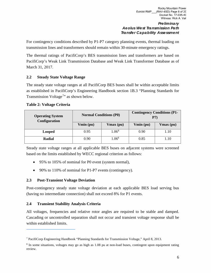
For contingency conditions described by P1-P7 category planning events, thermal loading on transmission lines and transformers should remain within 30-minute emergency ratings.
The thermal ratings of PacifiCorp’s BES transmission lines and transformers are based on PacifiCorp’s Weak Link Transmission Database and Weak Link Transformer Database as of March 31, 2017.
2.2 Steady State Voltage Range
The steady state voltage ranges at all PacifiCorp BES buses shall be within acceptable limits as established in PacifiCorp’s Engineering Handbook section 1B.3 “Planning Standards for Transmission Voltage7” as shown below.
Table 2: Voltage Criteria
Operating System Configuration
Normal Conditions (P0) Contingency Conditions (P1-P7)
Vmin (pu) Vmax (pu) Vmin (pu) Vmax (pu)
Looped 0.95 1.068 0.90 1.10
Radial 0.90 1.068 0.85 1.10
Steady state voltage ranges at all applicable BES buses on adjacent systems were screened based on the limits established by WECC regional criterion as follows:
• 95% to 105% of nominal for P0 event (system normal),
• 90% to 110% of nominal for P1-P7 events (contingency).
2.3 Post-Transient Voltage Deviation
Post-contingency steady state voltage deviation at each applicable BES load serving bus (having no intermediate connection) shall not exceed 8% for P1 events.
2.4 Transient Stability Analysis Criteria
All voltages, frequencies and relative rotor angles are required to be stable and damped. Cascading or uncontrolled separation shall not occur and transient voltage response shall be within established limits.
7 PacifiCorp Engineering Handbook “Planning Standards for Transmission Voltage,” April 8, 2013. 8 In some situations, voltages may go as high as 1.08 pu at non-load buses, contingent upon equipment rating review.
6
Preliminary Aeolus West Transmission Path
Transfer Capability Assessment
2.5 Transient Voltage Response
Transient stability voltage response criteria are based on WECC Regional Performance Criteria WR1.3 through WR1.5 as follows:
• Transient stability voltage response at the applicable BES buses serving load (having no intermediate connection) shall recover to at least 80% of pre-contingency voltage within 20 seconds of the initiating event for all P1-P7 category events, for each applicable bus serving load.
• For voltage swings following fault clearing and voltage recovery above 80%, voltage dips at each applicable BES bus serving load (having no intermediate buses) shall not dip below 70% of pre-contingency voltage for more than 30 cycles or remain below 80% of pre-contingency voltage for more than two seconds for all P1-P7 category events.
• For contingencies without a fault (P2-1 category event), voltage dips at each applicable BES bus serving load (having no intermediate buses) shall not dip below 70% of pre-contingency voltage for more than 30 cycles or remain below 80% of pre-contingency voltage for more than two seconds.
The following criteria were used to investigate the potential for cascading and uncontrolled islanding:
• Load interruption due to successive line tripping for thermal violations shall be confined to the immediate impacted areas and shall not propagate to other areas. The highest available emergency rating is used to determine the tripping threshold for lines or transformers when evaluating a scenario that may lead to cascading.
• Voltage deficiencies caused by either the initiating event or successive line tripping shall be confined to the immediate impacted areas, and shall not propagate to other areas.
Positive damping in stability analysis is demonstrated by showing that the amplitude of power angle or voltage magnitude oscillations after a minimum of 10 seconds is less than the initial post-contingency amplitude. Oscillations that do not show positive damping within a 30-second time frame shall be deemed unacceptable.
Stability studies shall be performed for planning events to determine whether the BES meets the performance requirements.
7
Preliminary Aeolus West Transmission Path
Transfer Capability Assessment
• Single contingencies (P1 category events): No generating unit shall pull out of synchronism (excludes generators being disconnected from the system by fault clearing action or by a special protection system).
• Multiple contingencies (P2-P7 category events): When a generator pulls out of synchronism in the simulations, the resulting apparent impedance swings shall not result in the tripping of any transmission system elements other than the generating unit and its directly connected facilities.
• Power oscillations are evaluated by exhibiting acceptable damping. The absence of positive damping within a 30-second time frame is considered un-damped.
3 Base Case Development
3.1 Base Case Selection
The base case development process involves selecting an approved WECC base case, updating the models to represent existing and planned facilities (D.2 Project transmission and wind generation facilities) and then tuning the cases to maximum transfer conditions on the WECC transmission path(s) being studied. For this study purpose, the published WECC base case that is close to the projects’ in-service date of November 2020, which has average load conditions based on 2021 load projection and availability of a stability case, was selected. The WECC approved base case 2021-22 HW (created on August 19, 2016) was selected, which meets these criteria. This study focused on simultaneous transmission path interaction in the Wyoming area between the Aeolus West and the TOT 4B transmission paths; however, other transmission paths such as Yellowtail South (non-WECC path), Jim Bridger West, TOT 1A and TOT 3 (See Appendix A for path definitions) were monitored throughout the study.
The various critical components for this study purpose from selected 2021-22 HW base case are listed below:
Table 3: Wyoming Load, Generation and Platte Normal Open Configuration in Base Case
North Wyoming PAC Load (including Wyodak load of 42 MW)
391 MW
North Wyoming - Western Area Power Administration (WAPA) Load
211 MW
Eastern Wyoming PAC Load (including DJ load of 56 MW) 474 MW
Eastern Wyoming PAC loads on WAPA system 95 MW
8
Preliminary Aeolus West Transmission Path
Transfer Capability Assessment
Central Wyoming Load (including JB load of 130 MW) 434 MW
Yellowtail South Flow 192 MW
Yellowtail Generation 140/260 MW (Online/Max)
WAPA’s Existing Small Generation9 in North Wyoming 26/50 MW(Online/Max)
WAPA’s Existing Small Generation10 in Eastern Wyoming 484/584 MW(Online/Max)
Gross Laramie River Generation I (WAPA’s swing machine) 605 MW(Max)
Gross Laramie River Generation II 590/605 MW(Online/Max)
Gross Dave Johnston (DJ) Generation 700/774 MW(Online/Max)
Total Existing PAC East Wyoming Wind11 Generation 885.7/1124 MW (Online/Max)
Rapid City DC W Tie 130 W2E (200 MW-bidirectional)
Stegall DC Tie 100 E2W (110 MW-bidirectional)
Sydney DC Tie 196 E2W (200 MW-bidirectional)
TOT 4A 627 MW
TOT 4B 469 MW
Jim Bridger (JB) Generation 2200 MW
Jim Bridger West Flow 2027 MW
TOT 3 1259.1 MW
TOT 1A 195 MW
Platte – Mustang 115 kV Normal Open point Platte – Normal Open
9 WAPA’s small generation in north Wyoming includes; Boysen, BBill, Heart MT, Shoshone, Spring Mtn 10 WAPA’s small generation in eastern Wyoming includes; Alcova, Fremont, Glendo, Guernsy, Kortes, Seminoe, CLR_1, SS_Gen1 AND CPGSTN 11 PAC eastern Wyoming wind generation includes; Root Creek, Three Buttes, Top of World, Glenrock, Rolling Hills, Dunlap. Seven Mile Hill, Foote Creek and High Plains wind generation
9
Preliminary Aeolus West Transmission Path
Transfer Capability Assessment
3.2 Generating Facility Additions
Because the specific size and location of new and repowered Wyoming wind generation associated with the EV2020 initiative will not be known until 1Q18, this study evaluated anticipated Wyoming wind generation options12 for the preliminary Aeolus West analysis, based on requests in the PacifiCorp Large Generation Interconnection (LGI) queue as a proxy for new resources. The following generating facility assumptions were made and added into the base case.
Table 4: Assumed Generation Projects
Proposed New Wind Facilities Project size Point of Interconnection
Aeolus/Freezeout/Shirley Basin Area 320 MW Freezeout 230 kV
250 MW Aeolus 230 kV
250 MW Shirley Basin 230 kV
250 MW Shirley Basin 230 kV
Foote Creek Area 99 MW Foote Creek – High Plains 230 kV line 230 kV
Repowered Wind Facilities13
High Plains/McFadden Ridge I Gen Repowering (+29.75 MW)
Glenrock Gen Repowering I (+27.65) 0.0 MW Windstar 230 kV
Glenrock Gen Repowering II (+27.65 MW)
0.0 MW Windstar 230 kV
TOTAL 1169 MW
See Appendix B for detail on repowered and new wind farm modelling assumptions.
12 An additional resource option is outline in Sensitivity Study - Section 5.B. 13 The repowered generation was modeled, but the repowered MW output was not increased in the base case, i.e. increase machine size was modeled, but output was limited to existing LGI agreement
10
Preliminary Aeolus West Transmission Path
Transfer Capability Assessment
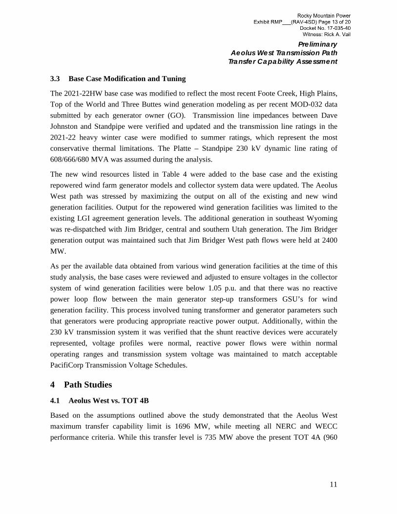
3.3 Base Case Modification and Tuning
The 2021-22HW base case was modified to reflect the most recent Foote Creek, High Plains, Top of the World and Three Buttes wind generation modeling as per recent MOD-032 data submitted by each generator owner (GO). Transmission line impedances between Dave Johnston and Standpipe were verified and updated and the transmission line ratings in the 2021-22 heavy winter case were modified to summer ratings, which represent the most conservative thermal limitations. The Platte – Standpipe 230 kV dynamic line rating of 608/666/680 MVA was assumed during the analysis.
The new wind resources listed in Table 4 were added to the base case and the existing repowered wind farm generator models and collector system data were updated. The Aeolus West path was stressed by maximizing the output on all of the existing and new wind generation facilities. Output for the repowered wind generation facilities was limited to the existing LGI agreement generation levels. The additional generation in southeast Wyoming was re-dispatched with Jim Bridger, central and southern Utah generation. The Jim Bridger generation output was maintained such that Jim Bridger West path flows were held at 2400 MW.
As per the available data obtained from various wind generation facilities at the time of this study analysis, the base cases were reviewed and adjusted to ensure voltages in the collector system of wind generation facilities were below 1.05 p.u. and that there was no reactive power loop flow between the main generator step-up transformers GSU’s for wind generation facility. This process involved tuning transformer and generator parameters such that generators were producing appropriate reactive power output. Additionally, within the 230 kV transmission system it was verified that the shunt reactive devices were accurately represented, voltage profiles were normal, reactive power flows were within normal operating ranges and transmission system voltage was maintained to match acceptable PacifiCorp Transmission Voltage Schedules.
4 Path Studies
4.1 Aeolus West vs. TOT 4B
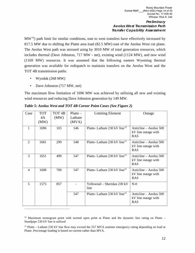
Based on the assumptions outlined above the study demonstrated that the Aeolus West maximum transfer capability limit is 1696 MW, while meeting all NERC and WECC performance criteria. While this transfer level is 735 MW above the present TOT 4A (960
11
Preliminary Aeolus West Transmission Path
Transfer Capability Assessment
MW14) path limit for similar conditions, east to west transfers have effectively increased by 817.5 MW due to shifting the Platte area load (82.5 MW) east of the Aeolus West cut plane. The Aeolus West path was stressed using by 3010 MW of total generation resources, which includes thermal (Dave Johnston, 717 MW - net), existing wind (1124 MW), and new wind (1169 MW) resources. It was assumed that the following eastern Wyoming thermal generation was available for redispatch to maintain transfers on the Aeolus West and the TOT 4B transmission paths:
• Wyodak (268 MW)
• Dave Johnston (717 MW, net)
The maximum flow limitation of 1696 MW was achieved by utilizing all new and existing wind resources and reducing Dave Johnston generation by 149 MW.
Table 5: Aeolus West and TOT 4B Corner Point Cases (See Figure 2)
Case TOT 4A
(MW)
TOT 4B (MW)
Platte – Latham (MVA)
Limiting Element Outage
1 1696 103 546 Platte- Latham 230 kV line15 Anticline – Aeolus 500 kV line outage with RAS
2 1681 299 548 Platte- Latham 230 kV line15 Anticline – Aeolus 500 kV line outage with RAS
3 1651 499 547 Platte- Latham 230 kV line15 Anticline – Aeolus 500 kV line outage with RAS
4 1608 700 547 Platte- Latham 230 kV line15 Anticline – Aeolus 500 kV line outage with RAS
5 1575 857 - Yellowtail – Sheridan 230 kV line
N-0
547 Platte- Latham 230 kV line15 Anticline – Aeolus 500 kV line outage with RAS
14 Maximum nomogram point with normal open point at Platte and the dynamic line rating on Platte – Standpipe 230 kV line is utilized 15 Platte – Latham 230 kV line flow may exceed the 557 MVA summer emergency rating depending on load at Platte. Percentage loading is based on current rather than MVA.
12
Preliminary Aeolus West Transmission Path
Transfer Capability Assessment
See Appendix C for power flow diagrams.
In the study, three different remedial action schemes (RAS) were considered for N-1 outages:
i. Aeolus RAS to trip up to 640 MW of wind generation depending on pre-outage flow conditions for any of the new transmission element outages between Aeolus – Jim Bridger.
ii. Freezeout RAS to trip up to 140 MW of generation in the Freezeout area for the Aeolus – Freezeout 230 kV line outage depending on the pre-outage flow conditions.
iii. Shirley Basin RAS to trip up to 60 MW of generation in the Shirley Basin area for the Aeolus – Shirley Basin 230 kV line outage depending on pre-outage flow conditions.
Figure 2: Aeolus West Vs TOT 4B Nomogram
Figure 2 depicts that the Aeolus West and TOT 4B path interaction is minimized with the addition of the D.2 Project, as indicated by the steeper curve (implying little or no path interaction) as compared to present TOT 4A/TOT 4B interaction. However, anytime the
0
100
200
300
400
500
600
700
800
900
0 200 400 600 800 1000 1200 1400 1600 1800
TOT
4B F
low
(MW
)
Aeolus West Flow (MW)
Wyoming System Operating Curve2022 Heavy Winter Loads
Normal Open Point: Platte115 kV
13
Preliminary Aeolus West Transmission Path
Transfer Capability Assessment
emergency dynamic line rating on Platte – Standpipe is lower than 651 MVA16 the nomogram in Figure 2 will be shifted to the left. Therefore, a new system operating limit (SOL) value will be identified to represent the real time rating restriction to the path. Additionally, the load at Platte substation can cause a shift in the nomogram; higher load at Platte can shift the curve towards the right and lower load at Platte can shift the curve towards the left, making it more conservative. This is due to the Platte – Latham 230 kV line being the limiting element, as mentioned in Table 5.
4.2 Base Case Development
The 2021-22 HW WECC case was modified to simultaneously stress the Aeolus West and the TOT 4B path flows. The Aeolus West path was stressed using approximately 2861 MW of eastern Wyoming resource from a total of 3010 MW (existing and future) wind and net coal resource. These resources were re-dispatched with Jim Bridger and Utah Valley resources such that the Jim Bridger West flows were maintained at 2400 MW. No additional resources were imported from WAPA into PAC to stress the Aeolus West path. Since the future resources in eastern Wyoming are in excess of future available transmission capacity, Dave Johnston plant output was reduced in eastern Wyoming. The Shiprock, San Juan and Gladstone phase shifters were locked to regulate flow across the TOT 3 path between Colorado and Wyoming.
The TOT 4B path flows were adjusted between a minimum of 100 MW and a maximum of 857 MW. The Montana resources, up to 388 MW, were re-dispatched with WAPA (Dry Fork) to reduce TOT 4B flow or re-dispatched with PAC resources to increase the TOT 4B flow using Crossover, Rimrock and Steam Plant phase shifters in Montana.
4.3 Transient Stability Analysis
The stability analysis was performed using GE provided model (GE0501) for repowered and new wind generation. The generic model for the Root Creek wind model was updated to GE0501 (GE 1.85 units). Top of the World and Three Buttes were updated to GE 1.5 wind turbine model provided by GE for PTI V33. The generic WECC models were used for the Latham dynamic reactive device.
The transient stability study was performed for one (worst case) nomogram point of the Aeolus West vs. the TOT 4B nomogram curve. The nomogram point with the heaviest
16 The highest loading on the Platte – Standpipe 230 kV line as per power flow analysis based on study assumption.
14
Preliminary Aeolus West Transmission Path
Transfer Capability Assessment
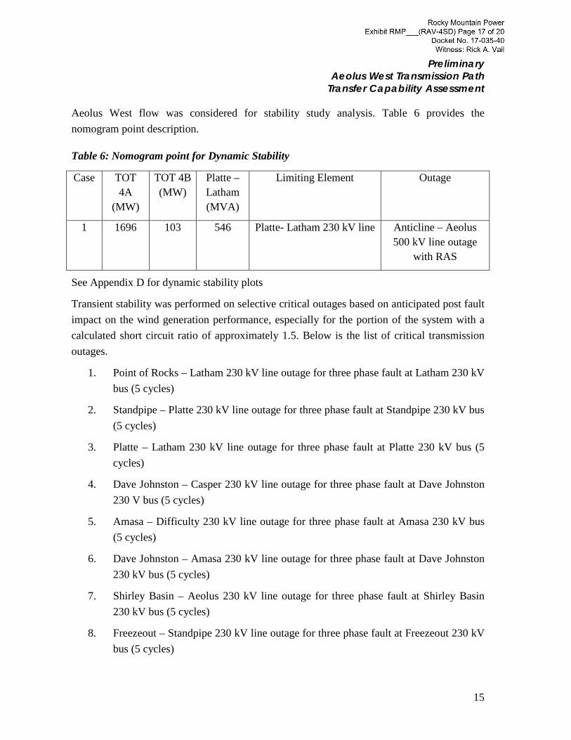
Aeolus West flow was considered for stability study analysis. Table 6 provides the nomogram point description.
Table 6: Nomogram point for Dynamic Stability
Case TOT 4A
(MW)
TOT 4B (MW)
Platte – Latham (MVA)
Limiting Element Outage
1 1696 103 546 Platte- Latham 230 kV line Anticline – Aeolus 500 kV line outage
with RAS
See Appendix D for dynamic stability plots
Transient stability was performed on selective critical outages based on anticipated post fault impact on the wind generation performance, especially for the portion of the system with a calculated short circuit ratio of approximately 1.5. Below is the list of critical transmission outages.
1. Point of Rocks – Latham 230 kV line outage for three phase fault at Latham 230 kV bus (5 cycles)
2. Standpipe – Platte 230 kV line outage for three phase fault at Standpipe 230 kV bus (5 cycles)
3. Platte – Latham 230 kV line outage for three phase fault at Platte 230 kV bus (5 cycles)
4. Dave Johnston – Casper 230 kV line outage for three phase fault at Dave Johnston 230 V bus (5 cycles)
5. Amasa – Difficulty 230 kV line outage for three phase fault at Amasa 230 kV bus (5 cycles)
6. Dave Johnston – Amasa 230 kV line outage for three phase fault at Dave Johnston 230 kV bus (5 cycles)
7. Shirley Basin – Aeolus 230 kV line outage for three phase fault at Shirley Basin 230 kV bus (5 cycles)
8. Freezeout – Standpipe 230 kV line outage for three phase fault at Freezeout 230 kV bus (5 cycles)
15
Preliminary Aeolus West Transmission Path
Transfer Capability Assessment
9. Aeolus – Freezeout 230 kV line outage for three phase fault at Aeolus 230 kV bus (5 cycles)
10. Aeolus – Anticline 500 kV line outage for three phase fault at Aeolus 230 kV bus (4 cycle fault and 10 cycles for RAS operation)
11. Aeolus – Anticline 500 kV line outage for three phase fault at Anticline 345 kV bus (4 cycle fault and 10 cycles for RAS operation)
12. Riverton – Wyopo 230 kV line outage for three phase fault at Riverton 230 kV bus (5 cycles)
Observation 1: During the stability analysis it was identified that the Latham SVC model tripped on high voltage for Platte – Standpipe 230 kV line outage. Following the fault, the Latham SVC is radial from Point of Rocks substation, causing high voltage at Latham 230 kV bus and tripping the SVC model. This issue can be resolved with changing the SVC operating parameter such that the SVC blocks VAR supply for voltage below a certain voltage level.
Observation 2: Additionally the slowest voltage recovery following the fault clearing occurs for a fault at either the Anticline or the Jim Bridger 345 kV bus followed by the loss of the new Aeolus – Anticline/Jim Bridger segment and operation of the Aeolus RAS to drop generation, causing the largest angular separation between Jim Bridger and Dave Johnston. For local fault conditions, the GE wind turbine models ramp down momentarily, whereas the models do not ramp for remote faults.
Due to the fault being on the remote end (at Anticline or Jim Bridger) of the new Aeolus – Bridger line segment, which is isolated from the wind farms, the voltage depression seen by the wind generating units (modelled as current source) are not as low, the power output is much higher during the fault and power output recovery is much faster after the fault as compared to the fault close to Aeolus. The remote fault results in more stress on the system during the fault and post fault, which leads to slower voltage recovery. The synchronous machines (modelled as voltage source) at Dave Johnston and Jim Bridger (one unit offline in the stress base case) try to recover the system voltage, which leads to higher angular separation between the two buses. Thus, the loss of the Aeolus – Anticline/Jim Bridger segment with a remote fault is the most severe.
This issue can be mitigated by effectively sizing dynamic reactive device at Latham to boost the system voltage. This disturbance did not result in system instability or system separation.
16
Preliminary Aeolus West Transmission Path
Transfer Capability Assessment
Additionally, the stability analysis demonstrated that all planning events met stability performance criteria.
5 Sensitivity Analysis
A. A sensitivity study was performed to replace the SVC dynamic device model at Latham with a generic STATCOM model. The dynamic simulations were performed for a stressed base case and the STATCOM model displayed behavior similar to the SVC model. High post fault voltage conditions require model data adjustments to prevent SVC and STATCOM model blocking and tripping.
B. A sensitivity analysis was performed to evaluate the system impacts of increasing the magnitude and changing the location of generation resources identified in the Assumed Generation Projects in Table 4. As part of this analysis, assumed wind generation was increased from 1169 MW to 1270 MW, by increasing the repowered generation by 137.5 MW and adding 240 MW of new generation in the Bighorn area of northern Wyoming, and reducing the new wind generation at Shirley Basin from 500 MW to 250 MW. (Other generation adjustments were made for loads and resource balancing.) Due to reduced generation in southeast Wyoming, Aeolus West transfer capability limit increased to 1790 MW. The limiting element was the Platte – Latham 230 kV line emergency thermal rating following outage of the Bridger/Anticline – Aeolus facilities and initiation of associated generating tripping.
The study also identified two different RAS schemes to trip generation for N-1 outage:
i. Aeolus RAS to trip up to 640 MW of wind generation depending on pre outage flow conditions for any of the new transmission element outage between Aeolus – Anticline/Jim Bridger segment.
ii. Freezeout RAS to trip up to 190 MW of generation in Freezeout area for Aeolus – Freezeout 230 kV line outage depending on pre outage flow conditions.
There were no additional system improvement requirements identified.
17
Preliminary Aeolus West Transmission Path
Transfer Capability Assessment
6 Study Conclusions
Technical studies demonstrated that with the addition of the planned D.2 Project facilities to the Wyoming transmission system, system performance will meet all NERC and WECC performance criteria.
Preliminary power flow studies demonstrate that by utilizing existing and planned southeast Wyoming resources4, the Aeolus West transmission path can transfer up to 1696 MW under simultaneous transfer conditions with the TOT 4B transmission path, effectively5 increasing the east to west transfer levels across Wyoming by 817.5 MW. Power flow findings also indicated:
• Dynamic voltage control is necessary at the Latham 230 kV substation to mitigate low voltage conditions resulting from loss of Bridger/Anticline – Aeolus transmission facilities.
• Under certain operating conditions, three different Remedial Action Schemes (RAS) will need to be implemented to trip generation following outage of specific transmission facilities.
• The location (and output level) of new and repowered wind resources can influence the transfer capability level across the Aeolus West transmission path.
While a wide range of disturbances were evaluated, dynamic stability studies identified that the slowest post fault voltage recovery will occur for a fault at Anticline or Jim Bridger 345 kV bus followed by loss of the Bridger/Anticline – Aeolus transmission segment and the planned operation of a generation tripping (RAS) scheme. The stability analysis demonstrated that all planned system events met the stability performance criteria.