16
N E W S Rodless Cylinders Series 52 *DOC-serie 52 ING.qxd 6-04-2005 10:31 Pagina 3

N E WS
Rodless Cy l indersSer ies 52
*DOC-serie 52 ING.qxd 6-04-2005 10:31 Pagina 3

Double-acting, magnetic, cushionedø 25, 32, 40
Rodless Cylinders Series 52
T h e c o m p a n y r e s e r v e s t h e r i g h t t o v a r y m o d e l s a n d d i m e n s i o n s w i t h o u t n o t i c e .T h e s e p r o d u c t s a r e d e s i g n e d f o r i n d u s t r i a l a p p l i c a t i o n s a n d a r e n o t s u i t a b l e f o r s a l e t o t h e g e n e r a l p u b l i c .
S E R I E S52 N e w s 2 0 0 5
001
The Rodless Cylinders Series 52 are availablein 3 diameters, 25, 32 and 40 mm and comesin three main versions such as Basic (M),with Slide bearing (G) and with Roller bearings (R). Furthermore these three mainversions are each available with either standard- or short carriage to cover a widerrange of applications. A permanent magnet is assembled on the piston allowing the position to be detectedby means of proximity switches positioned in grooves located on three sides on the cylinder profile. The cylinder is equippedwith an end stroke cushioning which can beregulated by means of a screw located on each end cover of the cylinder. The Rodless Cylinder Series 52 is also availablein versions with air supply from one side(end cover) only if needed.
Three main versions, Basic, Slide bearing and Roller bearingExtra short carriageas option for all versions Possibility of feeding both chambers from one side only
AC
TU
AT
OR
S
*DOC-serie 52 ING.qxd 6-04-2005 10:31 Pagina 4

AC
TU
AT
OR
S
T h e c o m p a n y r e s e r v e s t h e r i g h t t o v a r y m o d e l s a n d d i m e n s i o n s w i t h o u t n o t i c e .T h e s e p r o d u c t s a r e d e s i g n e d f o r i n d u s t r i a l a p p l i c a t i o n s a n d a r e n o t s u i t a b l e f o r s a l e t o t h e g e n e r a l p u b l i c . 002
S E R I E SN e w s 2 0 0 5 52
52M2P25A 52M2P32A 52M2P40A52M8P25A 52M8P32A 52M8P40A
Piston Ø (mm) 25 32 40
Connection G1/8 G1/8 G1/4
Cushioning length (mm) 24 28 45
Mass at 0 mm stroke (kg) 0,88 1,40 2,41
Additional mass per 100 mm (kg) 0,30 0,39 0,52
Operating pressure (bar) 1 ÷ 8
Temperature range - 10 °C ÷ + 70 °C
Medium clean air, without lubrication*
If speeds exceed 1 m/s lubricated air is recommended.
Stroke length (mm) arbitrary up to 6000
Materials Al (anodized), plastic
Seals: NBR, PU
* If lubricated air is used, it is recommended to use ISO VG32 oil. Once applied the lubrication should never be interrupted.
GENERAL DATA 52M2P....52M8P....
52M2C25A 52M2C32A 52M2C40A52M8C25A 52M8C32A 52M8C40A
Piston Ø (mm) 25 32 40
Connection G1/8 G1/8 G1/4
Cushioning length (mm) 24 28 45
Mass at 0 mm stroke (kg) 0,62 0,96 1,65
Additional mass per 100 mm (kg) 0,30 0,39 0,52
Operating pressure (bar) 1 ÷ 8
Temperature range - 10 °C ÷ + 70 °C
Medium clean air, without lubrication*
If speeds exceed 1 m/s lubricated air is recommended.
Stroke length (mm) arbitrary up to 6000
Materials Al (anodized), plastic
Seals: NBR, PU
* If lubricated air is used, it is recommended to use ISO VG32 oil. Once applied the lubrication should never be interrupted.
GENERAL DATA 52M2C....52M8C....
52G2P25A 52G2P32A 52G2P40A52G8P25A 52G8P32A 52G8P40A
Piston Ø (mm) 25 32 40
Connection G1/8 G1/8 G1/4
Cushioning length (mm) 24 28 45
Mass at 0 mm stroke (kg) 1,31 2,09 3,58
Additional mass per 100 mm (kg) 0,30 0,39 0,52
Operating pressure (bar) 1 ÷ 8
Temperature range - 10 °C ÷ + 70 °C
Medium clean air, without lubrication*
If speeds exceed 1 m/s lubricated air is recommended.
Stroke length (mm) arbitrary up to 6000
Materials Al (anodized), plastic
Seals: NBR, PU
* If lubricated air is used, it is recommended to use ISO VG32 oil. Once applied the lubrication should never be interrupted.
GENERAL DATA 52G2P....52G8P....
*DOC-serie 52 ING.qxd 6-04-2005 10:31 Pagina 5

AC
TU
AT
OR
S
T h e c o m p a n y r e s e r v e s t h e r i g h t t o v a r y m o d e l s a n d d i m e n s i o n s w i t h o u t n o t i c e .T h e s e p r o d u c t s a r e d e s i g n e d f o r i n d u s t r i a l a p p l i c a t i o n s a n d a r e n o t s u i t a b l e f o r s a l e t o t h e g e n e r a l p u b l i c .003
N e w s 2 0 0 5S E R I E S52
52G2C25A 52G2C32A 52G2C40A52G8C25A 52G8C32A 52G8C40A
Piston Ø (mm) 25 32 40
Connection G1/8 G1/8 G1/4
Cushioning length (mm) 24 28 45
Mass at 0 mm stroke (kg) 0,88 1,35 2,30
Additional mass per 100 mm (kg) 0,30 0,39 0,52
Operating pressure (bar) 1 ÷ 8
Temperature range - 10 °C ÷ + 70 °C
Medium clean air, without lubrication*
If speeds exceed 1 m/s lubricated air is recommended.
Stroke length (mm) arbitrary up to 6000
Materials Al (anodized), plastic
Seals: NBR, PU
* If lubricated air is used, it is recommended to use ISO VG32 oil. Once applied the lubrication should never be interrupted.
GENERAL DATA 52G2C....52G8C....
52R2P25A 52R2P32A 52R2P40A52R8P25A 52R8P32A 52R8P40A
Piston Ø (mm) 25 32 40
Connection G1/8 G1/8 G1/4
Cushioning length (mm) 24 28 45
Mass at 0 mm stroke (kg) 1,97 2,96 5,89
Additional mass per 100 mm (kg) 0,42 0,48 0,74
Operating pressure (bar) 1,5 ÷ 8 1 ...8 1 ...8
Temperature range - 10 °C÷ .+ 70 °C
Medium clean air, without lubrication*
If speeds exceed 1 m/s lubricated air is recommended.
Stroke length (mm) arbitrary up to 6000
Materials Al (anodized), plastic, hardened steel
Seals: NBR, PU
* If lubricated air is used, it is recommended to use ISO VG32 oil. Once applied the lubrication should never be interrupted.
GENERAL DATA 52R2P....52R8P....
52R2C25A 52R2C32A 52R2C40A52R8C25A 52R8C32A 52R8C40A
Piston Ø (mm) 25 32 40
Connection G1/8 G1/8 G1/4
Cushioning length (mm) 24 28 45
Mass at 0 mm stroke (kg) 1,33 1,91 3,84
Additional mass per 100 mm (kg) 0,42 0,48 0,74
Operating pressure (bar) 1,5 ÷ 8 1 ...8 1 ...8
Temperature range - 10 °C ÷ + 70 °C
Medium clean air, without lubrication*
If speeds exceed 1 m/s lubricated air is recommended.
Stroke length (mm) arbitrary up to 6000
Materials Al (anodized), plastic, hardened steel
Seals: NBR, PU
* If lubricated air is used, it is recommended to use ISO VG32 oil. Once applied the lubrication should never be interrupted.
GENERAL DATA 52R2C....52R8C....
*DOC-serie 52 ING.qxd 6-04-2005 10:31 Pagina 6
AC
TU
AT
OR
S
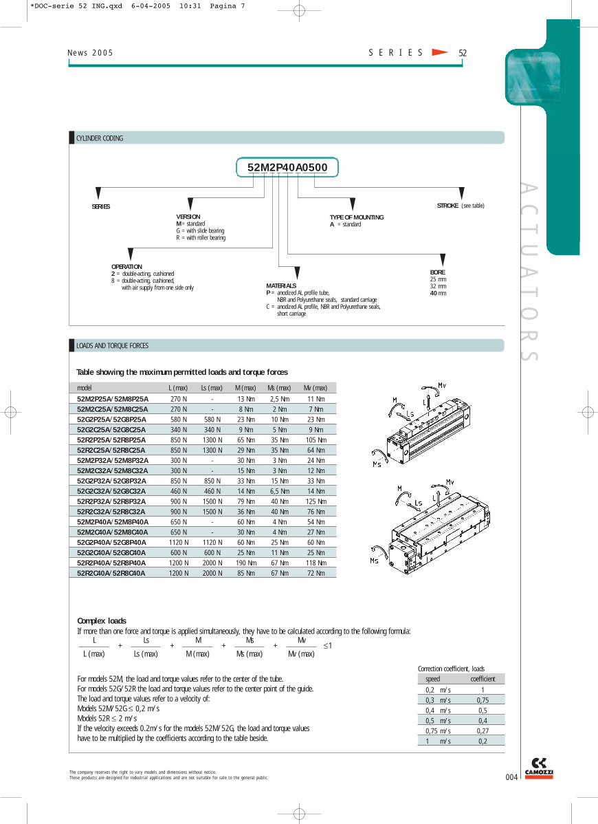
Correction coefficient, loadsspeed coefficient
0,2 m/s 10,3 m/s 0,750,4 m/s 0,50,5 m/s 0,40,75 m/s 0,271 m/s 0,2
model L (max) Ls (max) M (max) Ms (max) Mv (max)
52M2P25A/52M8P25A 270 N - 13 Nm 2,5 Nm 11 Nm52M2C25A/52M8C25A 270 N - 8 Nm 2 Nm 7 Nm52G2P25A/52G8P25A 580 N 580 N 23 Nm 10 Nm 23 Nm52G2C25A/52G8C25A 340 N 340 N 9 Nm 5 Nm 9 Nm52R2P25A/52R8P25A 850 N 1300 N 65 Nm 35 Nm 105 Nm52R2C25A/52R8C25A 850 N 1300 N 29 Nm 35 Nm 64 Nm52M2P32A/52M8P32A 300 N - 30 Nm 3 Nm 24 Nm52M2C32A/52M8C32A 300 N - 15 Nm 3 Nm 12 Nm52G2P32A/52G8P32A 850 N 850 N 33 Nm 15 Nm 33 Nm52G2C32A/52G8C32A 460 N 460 N 14 Nm 6,5 Nm 14 Nm52R2P32A/52R8P32A 900 N 1500 N 79 Nm 40 Nm 125 Nm52R2C32A/52R8C32A 900 N 1500 N 36 Nm 40 Nm 76 Nm52M2P40A/52M8P40A 650 N - 60 Nm 4 Nm 54 Nm52M2C40A/52M8C40A 650 N - 30 Nm 4 Nm 27 Nm52G2P40A/52G8P40A 1120 N 1120 N 60 Nm 25 Nm 60 Nm52G2C40A/52G8C40A 600 N 600 N 25 Nm 11 Nm 25 Nm52R2P40A/52R8P40A 1200 N 2000 N 190 Nm 67 Nm 118 Nm52R2C40A/52R8C40A 1200 N 2000 N 85 Nm 67 Nm 72 Nm
T h e c o m p a n y r e s e r v e s t h e r i g h t t o v a r y m o d e l s a n d d i m e n s i o n s w i t h o u t n o t i c e .T h e s e p r o d u c t s a r e d e s i g n e d f o r i n d u s t r i a l a p p l i c a t i o n s a n d a r e n o t s u i t a b l e f o r s a l e t o t h e g e n e r a l p u b l i c . 004
N e w s 2 0 0 5 S E R I E S 52
CYLINDER CODING
52M2P40A0500
SERIES
VERSIONM = standardG = with slide bearingR = with roller bearing
OPERATION2 = double-acting, cushioned8 = double-acting, cushioned,
with air supply from one side only MATERIALSP = anodized AL profile tube,
NBR and Polyurethane seals, standard carriageC = anodized AL profile, NBR and Polyurethane seals,
short carriage
BORE 25 mm32 mm40 mm
TYPE OF MOUNTING A = standard
STROKE (see table)
LOADS AND TORQUE FORCES
Complex loads If more than one force and torque is applied simultaneously, they have to be calculated according to the following formula:
Table showing the maximum permitted loads and torque forces
For models 52M, the load and torque values refer to the center of the tube.For models 52G/52R the load and torque values refer to the center point of the guide.The load and torque values refer to a velocity of:Models 52M/52G ≤ 0,2 m/sModels 52R ≤ 2 m/sIf the velocity exceeds 0.2m/s for the models 52M/52G, the load and torque valueshave to be multiplied by the coefficients according to the table beside.
L
L (max)
Ls
Ls (max)
M
M (max)
Ms
Ms (max)
Mv
Mv (max)≤1++++
*DOC-serie 52 ING.qxd 6-04-2005 10:31 Pagina 7

AC
TU
AT
OR
SN e w s 2 0 0 5
005T h e c o m p a n y r e s e r v e s t h e r i g h t t o v a r y m o d e l s a n d d i m e n s i o n s w i t h o u t n o t i c e .
T h e s e p r o d u c t s a r e d e s i g n e d f o r i n d u s t r i a l a p p l i c a t i o n s a n d a r e n o t s u i t a b l e f o r s a l e t o t h e g e n e r a l p u b l i c .
S E R I E S52
END CUSHION DIAGRAM
The end cushion regulating screw has to be regulated to obtain a smooth movement at the end of stroke. In those applications which have different valuesthan the ones stated in the diagram (below),external shock-absorbers have to be used.The shock-absorber should be centrally located with respect to the center of the mass. The diagram applies for horizontal operations.
LOADS ACCORDING TO SUPPORTS DISTANCE
The charts below have been made according to a max. deflection of 0.5 mm and 1 mm when a load (N) is applied.The charts reported below give the max distance between two supports in order to stay within the deflection range given.
Mass (Kg)
Velo
city
(m/s
)
Deflection 1,0 mmDeflection 0,5 mm
Max. distance between supports (m)Max. distance between supports (m)
*DOC-serie 52 ING.qxd 6-04-2005 10:31 Pagina 8

AC
TU
AT
OR
S
DIMENSIONS
Series ø W E L1 I B G N L øAH7 øX S1 T Z C1 C U F F152M2P25A 25 100 149,6 200 G1/8 25 5 19 9,5 6 4,5 49 25 4,5 90 50 15 M5 752M2P32A 32 120 184,5 240 G1/8 25 5,5 19 9,5 6 5,5 58 32,3 7,5 130 45 15 M5 752M2P40A 40 150 222,6 300 G1/4 25 7 23 11,5 7 6,5 68 38,2 7,5 160 90 15 M5 9
Series H V S R P TG Q Q152M2P25A 70 22 45 60 M4 36 11 352M2P32A 100 22 54 69 M5 41 11 452M2P40A 130 22 64 82 M6 49 12 4
T h e c o m p a n y r e s e r v e s t h e r i g h t t o v a r y m o d e l s a n d d i m e n s i o n s w i t h o u t n o t i c e .T h e s e p r o d u c t s a r e d e s i g n e d f o r i n d u s t r i a l a p p l i c a t i o n s a n d a r e n o t s u i t a b l e f o r s a l e t o t h e g e n e r a l p u b l i c . 006
N e w s 2 0 0 5
Mod. 52M2P...
+ add the strokeK = cushion regulation screwThe cylinder has two supply ports “I” for both endcovers. The operator just needs to choose which one of the two ports to use on each end cover.The remaining ports have to be closed with a tap (two taps are supplied).
S E R I E S 52
DIMENSIONS
Mod. 52M8P...
Where no dimensions are presented, refer to dimensions of cylinder model 52M2P, The cylinder has six ports “I” located on one endcover.Three ports (x-h-w) to move the carriage in one direction and three (y-z-k) for the opposite direction. The operator just needs to choose which one of the three ports to use for each direction. The remaining ports have to be closed with taps (4 taps are supplied). With supporting feet (mod. B-52 / BA-52),ports “h” and “z” have to be closed with a tap.
Series ø T1 T2 T3 T4 L2 L3 I52M8P25A 25 13,5 29,5 13,5 28,5 8 11 G1/852M8P32A 32 17,5 34,5 17,5 34,5 9,5 9,5 G1/852M8P40A 40 15,5 38,2 20,5 42,5 11,5 11,5 G1/4
*DOC-serie 52 ING.qxd 6-04-2005 10:31 Pagina 9

AC
TU
AT
OR
S
DIMENSIONS
Series ø W L L1 I B G N E øAH7 øX R C F F1 U T V S S1 TG52M2C25A 25 67,5 9,5 135 G1/8 25 5 19 84,6 6 4,5 60 35 M5 7 15 25 22 45 49 3652M2C32A 32 77,5 9,5 155 G1/8 25 5,5 19 99,6 6 5,5 69 45 M5 7 15 32,3 22 54 58 4152M2C40A 40 95 11,5 190 G1/4 25 7 23 112,6 7 6,5 82 50 M5 9 15 38,3 22 64 68 49
Series P Z Q Q152M2C25A M4 4,5 11 352M2C32A M5 7,5 11 452M2C40A M6 7,5 12 4
+ add the strokeK = cushion regulation screwThe cylinder has two supply ports “I” for both endcovers. The operator just needs to choose which one of the two ports to use on each end cover. The remaining ports have to be closed with a tap (two taps are supplied).
DIMENSIONS
Series ø T1 T2 T3 T4 L2 L3 I52M8C25A 25 13,5 29,5 13,5 28,5 8 11 G1/852M8C32A 32 17,5 34,5 17,5 34,5 9,5 9,5 G1/852M8C40A 40 15,5 38,2 20,5 42,5 11,5 11,5 G1/4
Where no dimensions are presented, refer to dimensions of cylinder model 52M2CThe cylinder has six supply ports “I” located on one endcover.Three ports (x-h-w) to move the carriage in one direction and three (y-z-k) for the opposite direction. The operator just needs to choose which one of the three ports to use for each direction. The remaining ports have to be closed with taps (4 taps are supplied).With supporting feet (mod. B-52 / BA-52), ports “h” and “z” have to be closed with a tap.
N e w s 2 0 0 5
007T h e c o m p a n y r e s e r v e s t h e r i g h t t o v a r y m o d e l s a n d d i m e n s i o n s w i t h o u t n o t i c e .
T h e s e p r o d u c t s a r e d e s i g n e d f o r i n d u s t r i a l a p p l i c a t i o n s a n d a r e n o t s u i t a b l e f o r s a l e t o t h e g e n e r a l p u b l i c .
S E R I E S52
Mod. 52M8C...
Mod. 52M2C...
*DOC-serie 52 ING.qxd 6-04-2005 10:31 Pagina 10

AC
TU
AT
OR
S
DIMENSIONS
Series ø T1 T2 T3 T4 L2 L3 I52G8P25A 25 13,5 29,5 13,5 28,5 8 11 G1/852G8P32A 32 17,5 34,5 17,5 34,5 9,5 9,5 G1/852G8P40A 40 15,5 38,2 20,5 42,5 11,5 11,5 G1/4
T h e c o m p a n y r e s e r v e s t h e r i g h t t o v a r y m o d e l s a n d d i m e n s i o n s w i t h o u t n o t i c e .T h e s e p r o d u c t s a r e d e s i g n e d f o r i n d u s t r i a l a p p l i c a t i o n s a n d a r e n o t s u i t a b l e f o r s a l e t o t h e g e n e r a l p u b l i c . 008
N e w s 2 0 0 5 S E R I E S 52
Mod. 52G8P...
Where no dimensions are presented, refer to dimensions of cylinder model 52M2CThe cylinder has six supply ports “I” located on one endcover.Three ports (x-h-w) to move the carriage in one direction and three (y-z-k) for the opposite direction. The operator just needs to choose which one of the three ports to use for each direction. The remaining ports have to be closed with taps (4 taps are supplied).With supporting feet (mod. B-52 / BA-52), ports “h” and “z” have to be closed with a tap.
Mod. 52G2P...
+ add the strokeK = cushion regulation screwThe cylinder has two supply ports “I” for both endcovers. The operator just needs to choose which one of the two ports to use on each end cover. The remaining ports have to be closed with a tap (two taps are supplied).
DIMENSIONS
Series ø W E L1 I L T U N C F F1 D B A H G M J52G2P25A 25 100 159 200 G1/8 9,5 25 30 19 30 M5 8 10,4 50 12,5 8,6 6,4 4,3 -52G2P32A 32 120 191 240 G1/8 9,5 32,3 70 19 35 M5 11 10,4 50 16,9 8,6 6,4 4,3 M552G2P40A 40 150 246 300 G1/4 11,5 38,2 55 23 55 M6 12 10,4 80 10 8,8 6,4 4,3 -
Series J1 TG Z S R1 P V Q Q1 øY2 Y+0,2 øXH7 Y1 X1 Y3-0,02 C1+0,05 S1 R52G2P25A - 36 4,5 45 75 M4 59 11 3 4 4,4 4 4,5 5,5 4 40 49 6052G2P32A 9 41 7,5 54 83,8 M5 69 11 4 4 4,4 4 7 8 4 40 58 6952G2P40A - 49 7,5 64 100 M6 79 12 4 6 6,4 6 7 8 6 40 68 82
00 -0,05
*DOC-serie 52 ING.qxd 6-04-2005 10:32 Pagina 11

N e w s 2 0 0 5
009T h e c o m p a n y r e s e r v e s t h e r i g h t t o v a r y m o d e l s a n d d i m e n s i o n s w i t h o u t n o t i c e .
T h e s e p r o d u c t s a r e d e s i g n e d f o r i n d u s t r i a l a p p l i c a t i o n s a n d a r e n o t s u i t a b l e f o r s a l e t o t h e g e n e r a l p u b l i c .
S E R I E S52
AC
TU
AT
OR
S
DIMENSIONS
Series ø T1 T2 T3 T4 L2 L3 I52G8C25A 25 13,5 29,5 13,5 28,5 8 11 G1/852G8C32A 32 17,5 34,5 17,5 34,5 9,5 9,5 G1/852G8C40A 40 15,5 38,2 20,5 42,5 11,5 11,5 G1/4
DIMENSIONS
Series ø W E L1 I L T U N C F F1 D B A H G M J52G2C25A 25 67,5 94 135 G1/8 9,5 25 30 19 30 M5 8 10,4 50 12,5 8,6 6,4 4,3 -52G2C32A 32 77,5 106 155 G1/8 9,5 32,3 70 19 35 M5 11 10,4 50 16,9 8,6 6,4 4,3 M552G2C40A 40 95 136 190 G1/4 11,5 38,2 55 23 55 M6 12 10,4 80 10 8,6 6,4 4,3 -
Series J1 TG Z S R1 P V Q Q1 øY2 Y+0,2 øXH7 Y1 X1 Y3-0,02 C1 +0,05 S1 R52G2C25A - 36 4,5 45 75 M4 59 11 3 4 4,4 4 4,5 5,5 4 40 49 6052G2C32A 9 41 7,5 54 83,8 M5 69 11 4 4 4,4 4 7 8 4 40 58 6952G2C40A - 49 7,5 64 100 M6 79 12 4 6 6,4 6 7 8 6 40 68 82
Mod. 52G2C...
+ add the strokeK = cushion regulation screwThe cylinder has two supply ports “I” for both endcovers. The operator just needs to choose which one of the two ports to use on each end cover.The remaining ports have to be closed with a tap (two taps are supplied).
00 -0,05
Mod. 52G8C...
Where no dimensions are presented, refer to dimensions of cylinder model 52G2C. The cylinder has six ports “I” located on one end cover which supplies both cylinder chambers. Three ports (x-h-w) to move the carriage in one direction and three (y-z-k) for the opposite direction. The operator just needs to choose which one of the three ports to use for each direction. The remaining ports have to be closed with taps (four taps are supplied). With supporting feet (model B-52/BA-52), ports “h” and “z” have to be closed with a tap. The guide is applied on the left side of the carriage (can be applied on the right side on request).
*DOC-serie 52 ING.qxd 6-04-2005 10:32 Pagina 12

AC
TU
AT
OR
S
T h e c o m p a n y r e s e r v e s t h e r i g h t t o v a r y m o d e l s a n d d i m e n s i o n s w i t h o u t n o t i c e .T h e s e p r o d u c t s a r e d e s i g n e d f o r i n d u s t r i a l a p p l i c a t i o n s a n d a r e n o t s u i t a b l e f o r s a l e t o t h e g e n e r a l p u b l i c . 010
N e w s 2 0 0 5 S E R I E S 52
DIMENSIONS
Series ø W E L1 I L T U N C F F1 TG Z S R1 P V Q Q1 øY2 Y+0,2 øXH7 Y1 X1 Y3-0,02 C1+0,05 S1 R2 R52R2P25A 25 100 160 200 G1/8 9,5 25 40 19 40 M5 7,5 36 4,5 45 97 M4 68,2 11 3 4 4,4 4 7 8 4 40 49 71 6052R2P32A 32 120 201 240 G1/8 9,5 32,3 40 19 40 M6 9 41 5,5 54 108,8 M5 78 11 4 4 4,4 4 7 8 4 40 58 81,4 6952R2P40A 40 150 252 300 G1/4 11,5 38,2 55 23 55 M6 12 49 7,5 64 145 M6 90,5 12 4 6 6,4 6 7 8 6 40 68 104,5 82
DIMENSIONS
Series ø T1 T2 T3 T4 L2 L3 I52R8P25A 25 13,5 29,5 13,5 28,5 8 11 G1/852R8P32A 32 17,5 34,5 17,5 34,5 9,5 9,5 G1/852R8P40A 40 15,5 38,2 20,5 42,5 11,5 11,5 G1/4
Where no dimensions are presented, refer to dimensions of cylinder model 52R2P. The cylinder has six ports “I” located on one end cover which supplies both cylinder chambers. Three ports (x-h-w) to move the carriage in one direction and three (y-z-k) for the opposite direction. The operator just needs to choose which one of the three ports to use for each direction. The remaining ports have to be closed with taps (four taps are supplied). With supporting feet (model B-52/BA-52), ports “h” and “z” have to be closed with a tap. The guide is applied on the left side of the carriage (can be applied on the right side on request).
ff = these holes are not present in cylinder 25+ add the strokeK = cushion regulation screwThe cylinder has two supply ports “I” for both endcovers. The operator just needs to choose which one of the two ports to use on each end cover. The remaining ports have to be closed with a tap (two taps are supplied).
00
-0,05
Mod. 52R8P...
Mod. 52R2P...
*DOC-serie 52 ING.qxd 6-04-2005 10:32 Pagina 13
AC
TU
AT
OR
SN e w s 2 0 0 5
011T h e c o m p a n y r e s e r v e s t h e r i g h t t o v a r y m o d e l s a n d d i m e n s i o n s w i t h o u t n o t i c e .
T h e s e p r o d u c t s a r e d e s i g n e d f o r i n d u s t r i a l a p p l i c a t i o n s a n d a r e n o t s u i t a b l e f o r s a l e t o t h e g e n e r a l p u b l i c .
S E R I E S52
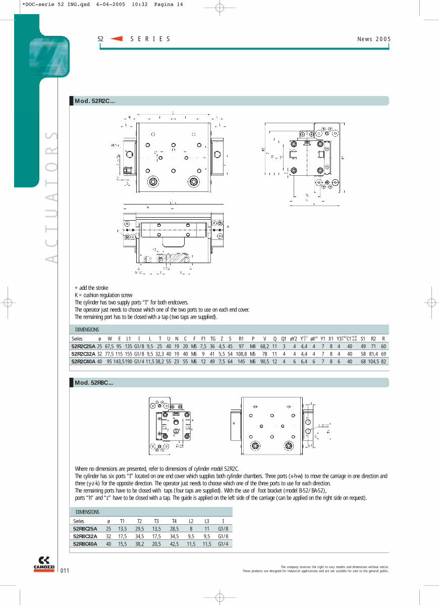
Where no dimensions are presented, refer to dimensions of cylinder model 52R2C.The cylinder has six ports “I” located on one end cover which supplies both cylinder chambers. Three ports (x-h-w) to move the carriage in one direction andthree (y-z-k) for the opposite direction. The operator just needs to choose which one of the three ports to use for each direction. The remaining ports have to be closed with taps (four taps are supplied). With the use of foot bracket (model B-52/BA-52), ports “h” and “z” have to be closed with a tap. The guide is applied on the left side of the carriage (can be applied on the right side on request).
+ add the strokeK = cushion regulation screwThe cylinder has two supply ports “I” for both endcovers. The operator just needs to choose which one of the two ports to use on each end cover. The remaining port has to be closed with a tap (two taps are supplied).
DIMENSIONS
Series ø W E L1 I L T U N C F F1 TG Z S R1 P V Q Q1 øY2 Y+0,2 øXH7 Y1 X1 Y3-0,02C1+0,05 S1 R2 R52R2C25A 25 67,5 95 135 G1/8 9,5 25 40 19 20 M5 7,5 36 4,5 45 97 M4 68,2 11 3 4 4,4 4 7 8 4 40 49 71 6052R2C32A 32 77,5 115 155 G1/8 9,5 32,3 40 19 40 M6 9 41 5,5 54 108,8 M5 78 11 4 4 4,4 4 7 8 4 40 58 81,4 6952R2C40A 40 95 143,5 190 G1/4 11,5 38,2 55 23 55 M6 12 49 7,5 64 145 M6 90,5 12 4 6 6,4 6 7 8 6 40 68 104,5 82
DIMENSIONS
Series ø T1 T2 T3 T4 L2 L3 I52R8C25A 25 13,5 29,5 13,5 28,5 8 11 G1/852R8C32A 32 17,5 34,5 17,5 34,5 9,5 9,5 G1/852R8C40A 40 15,5 38,2 20,5 42,5 11,5 11,5 G1/4
Mod. 52R2C...
Mod. 52R8C...
00 -0,05
*DOC-serie 52 ING.qxd 6-04-2005 10:32 Pagina 14
AC
TU
AT
OR
S
DIMENSIONS
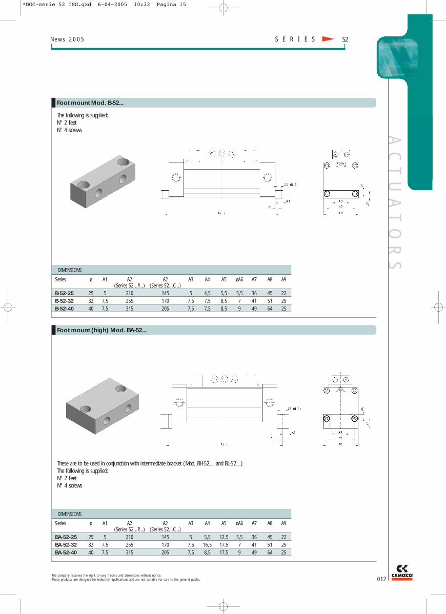
Series ø A1 A2 A2 A3 A4 A5 øA6 A7 A8 A9(Series 52...P...) (Series 52...C...)
BA-52-25 25 5 210 145 5 5,5 12,5 5,5 36 45 22BA-52-32 32 7,5 255 170 7,5 16,5 17,5 7 41 51 25BA-52-40 40 7,5 315 205 7,5 8,5 17,5 9 49 64 25
The following is supplied:N° 2 feetN° 4 screws
DIMENSIONS
Series ø A1 A2 A2 A3 A4 A5 øA6 A7 A8 A9(Series 52...P...) (Series 52...C...)
B-52-25 25 5 210 145 5 4,5 5,5 5,5 36 45 22B-52-32 32 7,5 255 170 7,5 7,5 8,5 7 41 51 25B-52-40 40 7,5 315 205 7,5 7,5 8,5 9 49 64 25
T h e c o m p a n y r e s e r v e s t h e r i g h t t o v a r y m o d e l s a n d d i m e n s i o n s w i t h o u t n o t i c e .T h e s e p r o d u c t s a r e d e s i g n e d f o r i n d u s t r i a l a p p l i c a t i o n s a n d a r e n o t s u i t a b l e f o r s a l e t o t h e g e n e r a l p u b l i c . 012
N e w s 2 0 0 5 S E R I E S 52
Foot mount Mod. B-52...
Foot mount (high) Mod. BA-52...
These are to be used in conjunction with intermediate bracket (Mod. BH-52... and BL-52...)The following is supplied:N° 2 feetN° 4 screws
*DOC-serie 52 ING.qxd 6-04-2005 10:32 Pagina 15

AC
TU
AT
OR
SN e w s 2 0 0 5
013T h e c o m p a n y r e s e r v e s t h e r i g h t t o v a r y m o d e l s a n d d i m e n s i o n s w i t h o u t n o t i c e .
T h e s e p r o d u c t s a r e d e s i g n e d f o r i n d u s t r i a l a p p l i c a t i o n s a n d a r e n o t s u i t a b l e f o r s a l e t o t h e g e n e r a l p u b l i c .
S E R I E S52
The following is supplied: screws for fixing the intermediate brackets to the tube profile. The cylinder can safely be mounted by using two intermediate brackets without using the feet bracket. The intermediate brackets BH-52-25 and BH-52-40 can be mounted either on sides X or Y or Z of the tube profile. The intermediate support model BH-52-32 can be mounted on side Z of the tube profile (if the application requires the assemblingof an intermediate bracket on sides X-Y, it is necessary to mount the intermediate bracket model BL-52-32).
DIMENSIONS
Series ø B1 B2 B3 B4 B5 ØB6BH-52-25 25 70 8 18,5 35 60 5,5BH-52-32 32 85 10 18,5 40 73 6,6BH-52-40 40 105 10 18,5 40 90,5 9
Intermediate brackets Mod. BH-52... and BL-52-32
*DOC-serie 52 ING.qxd 6-04-2005 10:32 Pagina 16
AC
TU
AT
OR
S
T h e c o m p a n y r e s e r v e s t h e r i g h t t o v a r y m o d e l s a n d d i m e n s i o n s w i t h o u t n o t i c e .T h e s e p r o d u c t s a r e d e s i g n e d f o r i n d u s t r i a l a p p l i c a t i o n s a n d a r e n o t s u i t a b l e f o r s a l e t o t h e g e n e r a l p u b l i c . 014
N e w s 2 0 0 5 S E R I E S 52
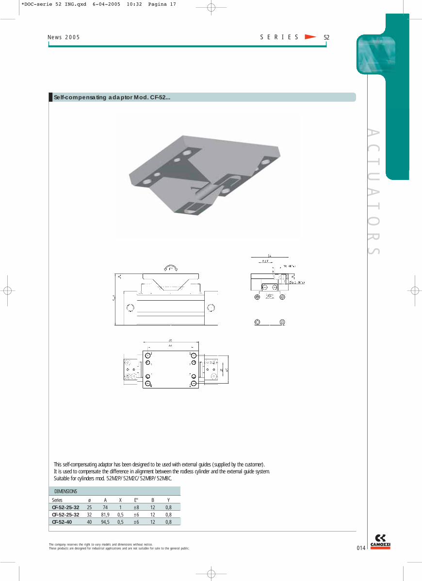
DIMENSIONS
Series ø A X E° B YCF-52-25-32 25 74 1 ±8 12 0,8CF-52-25-32 32 81,9 0,5 ±6 12 0,8CF-52-40 40 94,5 0,5 ±6 12 0,8
Self-compensating adaptor Mod. CF-52...
This self-compensating adaptor has been designed to be used with external guides (supplied by the customer). It is used to compensate the difference in alignment between the rodless cylinder and the external guide system.Suitable for cylinders mod. 52M2P/52M2C/52M8P/52M8C.
*DOC-serie 52 ING.qxd 6-04-2005 10:32 Pagina 17

w w w . c a m o z z i . c o m
93-1
005-
0GB0
48/0
4-05
MIX
CO
MU
NIC
AZ
ION
E -
MI
Camozzi spaVia Eritrea, 20/I25126 Brescia ItalyTel: int+39+030+37921 Fax: int+39+030+2400430E-mail: [email protected]: www.camozzi.com
Camozzi GmbH PneumaticPorschestrasse 173095 AlbershausenGermanyTel: int +49+7161+910100 Fax: int [email protected] www.camozzi.de
Camozzi Pneumatics Ltd.The Fluid Power CentreWatling Street NuneatonWarwickshire CV 11 6BQ Great BritainTel: int +44+24+7637 4114 Fax: int [email protected]
Camozzi Pneumatique 5, Rue Louis GattefosséParc de la Bandonnière 69800 Saint Priest FranceTel: int +33+478+213408 Fax: int [email protected]
Camozzi Benelux B.V.De Vijf Boeken 1 G2911 BL Nieuwerkerk a/d IJsselThe NetherlandsTel: int +31+180+316677Fax: int [email protected]
Camozzi Pneumatik ABBox 9214Bronsyxegatan 720039 Malmö SwedenTel: int.+46+40+222580Fax: [email protected]
Camozzi ApsMetalvej 7a4000 RoskildeDanmarkTel. int.+45-46-750202Fax [email protected]
Camozzi Pneumatic Ltd.Floor 14, Leningradskaya Street, 1-AHimki, Moscow Region141400 MoscowRussian FederationTel. int.+7+095+5754561Fax [email protected]
Camozzi-Pneumatic38 Larionova St95018 SimferopolUkraineTel: int +380+652+518198Fax: int [email protected]
Camozzi PneumaticKarbusheva St. 2 Off. 412246029 GomelByelorussiaTel: int +375+232478064Fax: int [email protected]
Camozzi Pneumatics Inc.2160 Redbud Blvd., TX 75069P.O. Box 2386, TX 75070McKinney - TexasU.S.A.Tel: int.+1+972+548-8885Fax: [email protected]
Camozzi Neumatica S.A. de C.V.Av. Santa Ana 18Parque Industrial Lerma52000 LermaMexicoTel: int.+52-728-2854153Fax: [email protected]/mexico
Camozzi do Brasil Ltda.Rua Estácio de Sá, 530Jd. Sta Genebra, CampinasCEP 13080-010 São PaoloBrazilTel.: int.+55-19-3208-3844Fax: [email protected]/brasil
Camozzi Neumatica S.A.Prof.Dr. Pedro Chutro 30481437 Buenos AiresArgentinaTel.: int.+54+11+49110816Fax.: [email protected]/arg
Camozzi Venezuela S.A.Calle 146 con Av. 62N°146-180P.O.Box 529Zona Industrial MaracaiboEdo. ZuliaVenezuelaTel: int +58+261+7360216Fax: int [email protected]
Camozzi Colombia, LtdaCarrera 34 # 22 D-02Santa Fé De BogotàColombiaTel: int.+57+1+5706828Fax: [email protected]/col
Camozzi Iran Co. Ltd.Motahari Ave. No. 243TeheranIranTel: int +9821-8736469 & int +9821-87321Fax: int [email protected]/ir
Shanghai Camozzi PneumaticControl Components Co, Ltd.415, Ren De Road200434 ShanghaiChinaTel: int +86+21+65363650Fax: int [email protected]/cn
Camozzi India Private LimitedC-130 Phase II Ext., Hosiery ComplexNoida - 201 305(uttar Pradesh) IndiaTel: +91+120+2560 061-65Fax: +91+120+2568 [email protected]/in
Camozzi Malaysia SDN BHD30, Jalan Pemberita, U1/49Seksyen U1Temasya Industrial Park40150 Shah AlamMalaysiaTel: +60+3+55690173Fax: [email protected]
*DOC-serie 52 ING.qxd 6-04-2005 10:32 Pagina 2


