16
Rodney Hunt A GA Industries Company Sluice Gates

Rodney HuntA GA Industries Company
Sluice Gates

PIPE COVER
FLOORSTAND
OPERATING STEM
STEM COUPLING
STEM GUIDE
GATE GUIDE
TOP WEDGE
SIDE WEDGE
THRUST NUT
DISC
BOTTOM WEDGE
ANCHOR BOLT
WALL THIMBLE
FRAME
OPENING
INVERT

The Typical
Sluice Gate Installation
The diagrams at left illustrate a typical sluice gate installation, showing a sluice gate with a wall thimble and crank operated floorstand. The more common component variations include handwheel actuators, benchstands, electric motor driven floorstands, hydraulic cylinders, self-contained gates and HY-Q flushbottom closure sluice gates. Other component arrangements are illustrated and described on pages 16 through 18.
In its simplest form, a sluice gate assembly consists of a frame, guides and a disc or sliding member. The gate is normally constructed of cast iron with bronze seats. Bronze wedges hold the disc tightly to the frame in the closed position.
Use of a wall thimble is the recommended method of mounting the gate because it provides a rigid, machined mounting surface. Sluice gates can also be mounted on flanged pipe or directly to concrete walls with anchor bolts.
The crank operated floorstand has a geared head with roller bearings to support the opening and closing thrust loads. The head is enclosed and mounted on a pedestal secured to a concrete floor or structural support. Although the crank operated floorstand is the most common method of controlling a gate, handwheel actuators, motor driven actuators and hydraulic cylinders can also be used.
The operating stem is a round shaft of bronze or stainless steel threaded on its upper portion to engage the floorstand lift nut. Sections of stem are joined together with cast bronze threaded and keyed couplings. When the length of an operating stem requires intermediate support an adjustable bronze bushed stem guide is furnished.
SLUICE GATE ASSEMBLY
WALL THIMBLE
CRANK OPERATED FLOORSTAND
OPERATING STEM
A typical sluice gate installation demonstrates how the various components of a sluice gate assembly are put together.
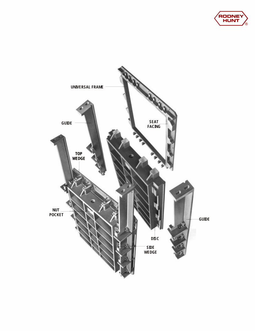
UNIVERSAL FRAME
SEAT FACING
GUIDE
NUT POCKET
TOPWEDGE
SIDEWEDGE
DISC
TOPWEDGE
GUIDE

KEYEDWEDGE PAD
SEAT FACING
NUT POCKET
SIDEWEDGE
DISC
TOPWEDGE
KEYEDWEDGE PAD
WEDGE PADBOLT
WEDGE PADBOLT
WEDGE PADKEYED TO GUIDE
ONE-PIECEGUIDE AND FRAME

The Wedge System
SIDE WEDGES
TOP AND BOTTOM WEDGES
Side wedges are keyed directly to the sluice gate disc to prevent rotation. Because the wedge and its contact surfaces are machined to match the exact angle of the bronze wedge seat, misalignment of the wedge is not possible, even through faulty field adjustment. After the wedge has been properly set using the adjusting bolt, a lock nut and hold-down stud are used as a double-lock feature to insure permanent setting. The accuracy of this wedge system results in low unit pressures uniformly distributed over bearing surfaces.
Both top and bottom wedges make use of a bronze wedge hook and wedge loop or seat. Top and bottom wedge seats are bolted directly to the cast iron frame and keyed so that they will not move under force. The wedge hooks are provided with an adjusting bolt with a lock nut to maintain the proper setting.
Adjustable wedges of high tensile strength cast bronze are furnished on all Rodney Hunt sluice gates. The number and location of wedges used on any gate depends on gate size and the amount and direction of water pressure acting on the sluice gate.
A gate subject to a seating head (a pressure which forces the disc and frame seats together) needs only side wedges to assure proper closure. Unseating heads, on the other hand, force the disc and frame seats apart, making additional wedges on top and bottom necessary.
There are exceptions. The HY-Q gate for unseating heads needs only top and side wedges because it makes use of a resilient seal rather than bronze seats at the invert. Gates in widths 24" and under, subject to unseating heads, are usually supplied only with side wedges because of the support inherent in the short span of the disc.
SIDE WEDGES TOP BOTTOM WEDGE WEDGE
A
B
C
D
EF
G
AB
C
D
EF
G
A
B
C
D
E F
G
LEGEND: A. BRONZE B. BRONZE C. BRONZE ADJUSTING SCREW D. HOLD DOWN E. BRONZE F. GATE G. GATE WEDGE WEDGE SEAT WITH LOCK NUT BOLT SEAT FACING DISC FRAME

The Self-Contained Sluice Gate
The selfcontained gate differs from other gates in that it absorbs the operating load created during opening and closing. This is accomplished through the use of a yoke, a supporting member mounted on the top of the extended guides. The thrust required to operate the gate is transmitted by the yoke and guides directly to the gate. In the conventional gate installation the load is absorbed by the floor or structure above the gate.
Self-contained gates can be furnished with non-rising stems where there is inadequate clearance above the gate for a rising stem. Because the non-rising stem may be in the medium, it cannot be cleaned and lubricated and excessive wear of the thrust nut may result. For that reason, non-rising stems should be used only when there is no alternative.
A self-contained gate has the same general features as a conventional gate. Its cast iron frame, disc and guides are identical except that the guides are extended to provide clearance for the sliding member in the open position. A cast iron or structural steel yoke is mounted on machined pads at the top of the guides. Opening thrusts are transferred through the yoke and guides to the gate. This arrangement eliminates the transmission of operating loads to the floor above.
All Rodney Hunt sluice gates are available as self-contained gates with yokes and with rising or non-rising stems. The self-contained gate is useful where space above the gate installation, or the absence of structural supports, limits the use of a separate operating floorstand or benchstand.

The HY-Q® Sluice Gate
A 78" x 96" FlushBottom Closure Sluice Gate is used to apportion raw sewage flow into grit chambers at the sewage treatment plant in Minneapolis, St. Paul.
As shown in the diagram, bottom disc construction and thickness of the resilient seal create a wide sealing surface against the machined cast iron stop bar. Also note that an effective seal is created by the vertical face of the seal, designated "A", compressing against the seat facing along the sides of the frame.
The flushbottom closure of the HY-Q gate eliminates the need for vertical walls or pockets on the invert surface which might otherwise impede flow. Its distinguishing design feature is a heavy resilient strip attached to the bottom of the gate disc which makes an extremely effective invert seal when compressed against the machined cast iron stop bar attached to the gate frame.
Because the HY-Q seal has a wide sealing surface rather than a narrow, line-contact surface common in other designs, unit pressures are much lower. Consequently, the possibility of seal damage from trapped debris lying between the invert and the gate disc is greatly reduced. Use for over thirty-five years since its development has proven that the HY-Q seal will withstand thousands of openings and closings without permanent deformation. If it becomes necessary, the seal can be changed without disturbing the invert or shutting off the flow of water.
Compressed resilient seal is clearly visible between the gate disc and stop bar. The flush line of the invert is indicated by the white line
RESILIENTSEAL
STOP BAR
A INVERT

Here’s when you can use
the Rodney Hunt HY-Q®
Sluice Gate to
exceptional advantage.
WHEN SILT AND DEBRIS
INTERFERE WITH OPERATION
WHEN MAXIMUM FLOW IS REQUIRED
WHEN COMPLETE DRAINAGE IS A MUST
WHEN DEFLECTION ON WIDE GATES IS A PROBLEM
Silt and debris are often a problem in conventional sluice gate installations. Foreign material may collect on the side of the concrete lift or in the boxout. Either of which is required when the gate invert is near or at the chamber floor. The HY-Q design allows continual flushing to prevent the accumulation of debris and silt.
The concrete lift or boxout beneath the gate creates a flow-restricting turbulence. The unobstructed invert surface available with the HY-Q gate has a high coefficient of discharge resulting in maximum flow through the opening for any given head condition.
The HY-Q sluice gate provides a natural drainage because the invert of the gate and the invert of the channel are at the same elevation.
Ail sluice gates deflect under load. Conventional design requires a heavy bottom rib to minimize bottom seat facing interference for seating head applications, and to insure proper wedge engagement and gate closure for unseating heads. As gate widths increase, this design problem becomes more severe. However, the HY-Q sluice gate eliminates this deflection problem because the invert is sealed by the contact of the resilient seal against the stop bar.

Special Rodney Hunt
Design Features
A wedge system that stays put. Because a Rodney Hunt bronze wedge is keyed directly to the sluice gate disc, it can't rotate. The wedge is machined to match the exact angle of the bronze wedge seat and double locked with a stud, adjusting screw and lack nut. This provides positive, fine wedge adjustment with permanent locking.
Locked in position gate guides and wedge seats. On Rodney Hunt universal frame sluice gates the guides are bolted to the frame and dowels are used to lock the guide in place.
On the integral frame gate, wedge seats are bolted and keyed to the frame to lock them in place. In this way, both horizontal and vertical movement is eliminated.

Wide compression gate seal. The HY-Q seal has proven itself in thousands of closings and openings without permanent deformation. Because of its wide sealing surface, unit pressures are lower and the possibility of seal damage is greatly reduced.
Stronger reinforcing ribs on the discs and guides make the Rodney Hunt universal frame gate more rigid offering greater support in critical areas.
Roller bearings and seals. AI! Rodney Hunt crank operated floorstands and benchstands are fully equipped with roller bearings far supporting the thrust nut and the pinion shafts. Seals are provided around the operating nut and the pinion shaft to prevent leakage of grease out of the unit and moisture into the unit.
Locked in place seat facings. These bronze seat facings, standard equipment on Rodney Hunt sluice gates are impacted into dovetailed grooves on the face of the disc and frame. They are work-hardened and are permanently locked into the iron castings. Thereafter, they are carefully machined to insure precise seating between the disc and frame.
Special Rodney Hunt
Design Features

Installation of Sluice Gates
WALL THIMBLES
They provide a smooth, machined surface on which to mount the gate, greatly reducing the possibility of gate distortion.Correctly installed, a wall thimble assures that the sluice gate will be plum in both directions.Attaching stud locations are fixed by the gate manufacturer. Wall thimble and gate are drilled to the same dimensions.The wall thimble eliminates the need for shimming and grouting, reducing gate installation costs and making the installation easier.Gates can be removed and installed again without disturbing the concrete.
Rodney Hunt sluice gates can be attached to wall thimbles embedded in the concrete, pipe flanges or directly to the concrete wall, and held in place with anchor bolts embedded in the concrete. However, the wall thimble is most frequently used and is the recommended method of installation. Here are some of the advantages of the use of wall thimbles:
They can be easily positioned in forms before the concrete is poured.
No additional form work is required for the opening when the length of the wall thimble is equal to the wall thickness.
These square and circular wall thimbles are typical of those shipped by Rodney Hunt every day. Note the use of plastic cap plugs to keep concrete out of the bolt holes during installation.

Wall Thimbles
ANCHOR BOLTS A typical installation of a HY-Q sluice gate with anchor bolts. Note the use of 1" of grout between the flange of the gate and the concrete wall. This is to prevent mounting the gate directly to the concrete surface which 'may not be flat.
Rodney Hunt offers three types of wall thimbles as standard equipment. They are the "F", "E" and "Flange and Bell". Variations such as the "L" and "C" section thimbles are also available. All wall thimbles are supplied with rectangular or circular openings that conform to the clear opening of the gate. Mounting flanges are rectangular to match the sluice gate frame. The mounting flange is slightly larger than the gate frame to prevent interference with the concrete adjacent to the thimble. The common wall thimble depths are 8", 12", and 24", and are usually furnished in depths corresponding to wall thickness.
Type "E" section wall thimbles ire recommended for sluice gates subject to high unseating pressures and very large gates. The "E" section thimble provides maximum strength and rigidity far eves the largest sluice gate installations and the mast severe conditions.
Flange and mechanical joint bell thimbles take the spigot end of a standard cast iron or cash ductile iron pipe.
Sluice gates can also be mounted on hook type anchor bolts that have been embedded in the concrete structure.
Type “F” wall thimble is the most widely used. The “F” section design is suitable for mounting sluice gates subject to any seating or moderate unseating pressure.

Installation Variations
This diagram shows a side wedge sluice gate with a two-piece operating stem and crank operated, single-speed floorstand. The gate is installed on an "F" section wall thimble extending completely through the concrete wall. This makes installation easier. Also note that a grout pad is used under the hoist to insure the proper alignment between hoist and operating stem.

Installation Variations
This 16" diameter gate, mounted on a flanged pipe extending from the wall, is a flange frame, side wedge, self-contained sluice gate using a non-rising stem. A T-handle wrench, engaging a 2" square operating nut in the floor-box is used to raise and lower the gate. Non-rising stem gates should not be used when it can be avoided, because the stem threads are in the medium where they cannot be regularly cleaned and lubricated.
This is a Rodney Hunt sluice gate with flush-bottom closure and side and top wedges. It is mounted on a type "F" wall thimble, the most widely used. Note that the hand-wheel operated floor-stand is mounted on a machined wall bracket. In this situation, a grout pad under the floor-stand is not necessary for true alignment.

Installation Variations
This is a Rodney Hunt side wedge sluice gate arranged for inverted operation. An inverted gate is used when there is not enough clearance for normal rising stem operation, or when weir type operation is desired. The gate is lowered to open, and raised to close, with an offset handwheel operated floor-stand installed on concrete with anchor bolts. The offset floor-stand eliminates the need for a special concrete support or wall bracket.
When limited head-room or insufficient clearance above the gate restricts the height of the gate. An extra wide sluice gate may be necessary. This flush-bottom sluice gate with side and top wedges is arranged for twin stem operation with two interconnected, two-speed, manually operated floor-stands. This arrangement can also be supplied with electric motor operation, providing torque protection and geared limit switches.


