RODSTAR-D/V Modern Design and Simulation of Rod Pumping Systems for Deviated or Vertical Wells eta Oilfield Services, Inc. 1901 E. Lambert Rd. Suite 108 La Habra, CA 90631 USA Telephone #: (562) 694-3297 Fax #: (562) 694-8641 www.gotheta.com or www.xspoc.com Email Addresses: John G. Svinos - President: [email protected]Terry Treiberg - XSPOC Dev. Manager: [email protected]Software Support: Kevin Lo: [email protected]Orders: Christy Kukula - Off. Manager: [email protected]
Transcript
RODSTAR-D/V Modern Design and Simulation
of Rod Pumping Systems for Deviated or Ver tical Wells
Theta Oilfield Services, Inc.1901 E. Lambert Rd. Suite 108La Habra, CA 90631 USATelephone #: (562) 694-3297Fax #: (562) 694-8641www.gotheta.com or www.xspoc.com
RODSTAR, RODSTAR-D, RODSTAR-V, RODDIAG, XDIAG, XBAL, and XTOOLS are trade-marks of Theta Oilfield Services, Inc..
Printed in the United States of AmericaSecond Edition, December 2011
RODSTAR | iii
ContentsTechnical Support v
System Requirements v
1 introduction 1
1 1 Program Features 1
1 2 Advanced Capabilities and Program Limitations 2
1 3 Help System 3
1 4 RODSTAR CD and Software Sentinel 3
2 Software installation 5
2 1 RODSTAR Installation 5
2 2 Questions About Installation 5
2 3 Installing the Software Sentinel 5
3 Starting and Setting Up RODSTAR 7
3 1 Starting RODSTAR 7
3 2 Exiting RODSTAR 8
3 3 Setting up RODSTAR 11
3 3 2 General setup options 11
3 3 3 Defaults, Limits, and Rod Guide Setup 12
3 3 4 Output Options 14
3 3 5 Pumping Unit Options 16
3 3 6 Rod Grade Options 19
3 3 7 Batch Mode Options 20
4 Running RODSTAR 23
4 1 RODSTAR’s User Interface 23
4 1 1 RODSTAR’s Help System 24
4 2 Entering Rod Pumping System Data 24
4 2 1 Entering Well Information Data 25
4 2 2 Entering Production Information 27
4 2 3 Entering Pump and Tubing Information Data 29
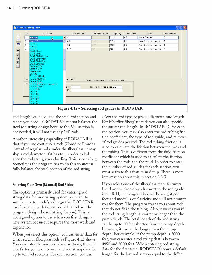
4 2 4 Entering Rod String Data 31
4 2 5 Entering Wellbore Deviation Data (RODSTAR-D) 36
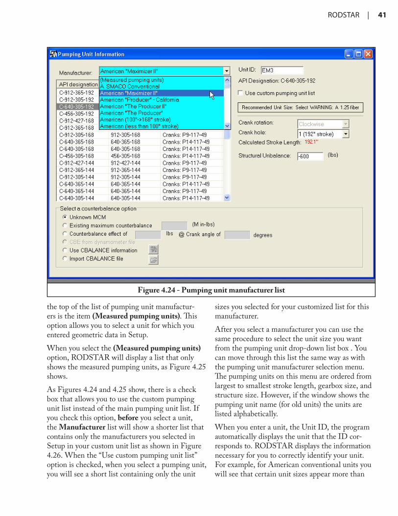
4 2 6 Entering Pumping Unit Data 40
iv | Table of Contents
4 2 7 Entering Motor Information and Energy Cost 50
5 Changing, Loading and Saving Data 53
5 1 Visual Input 53
5 2 Storing Data Files 53
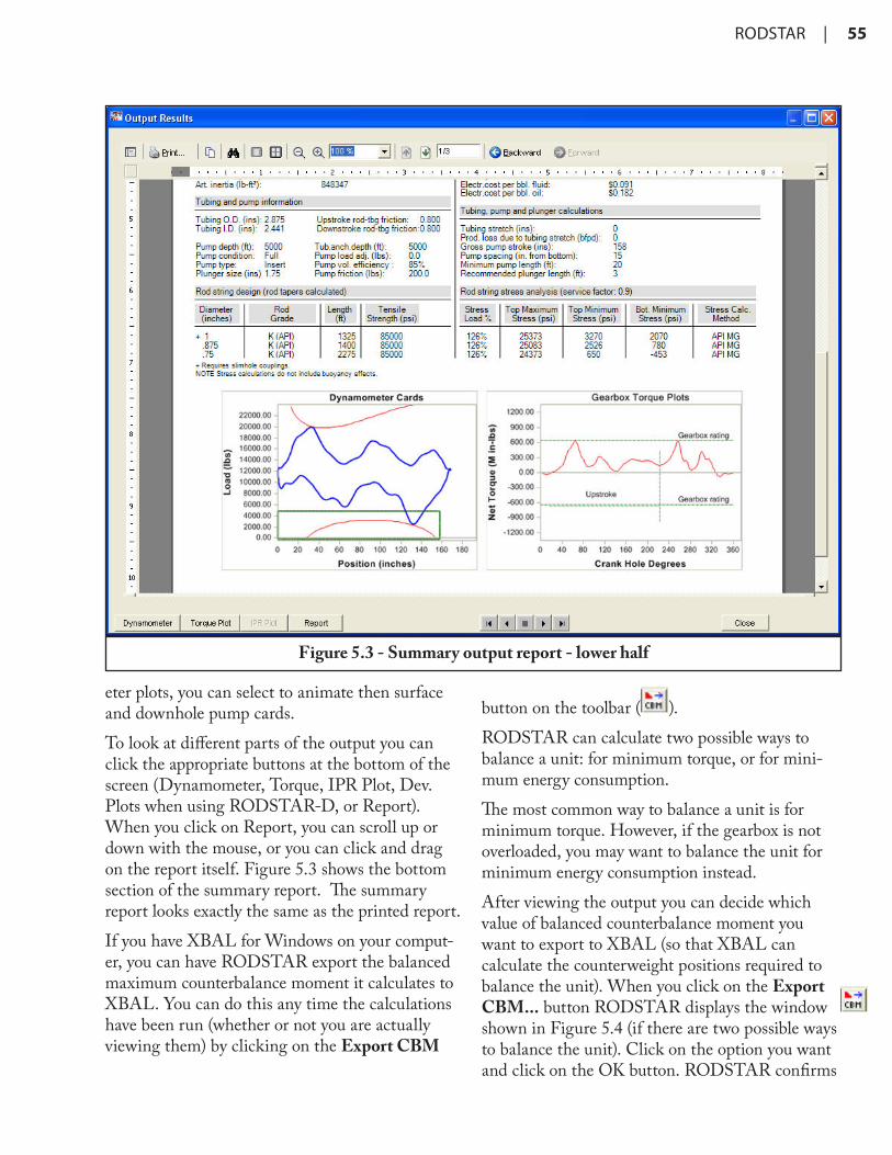
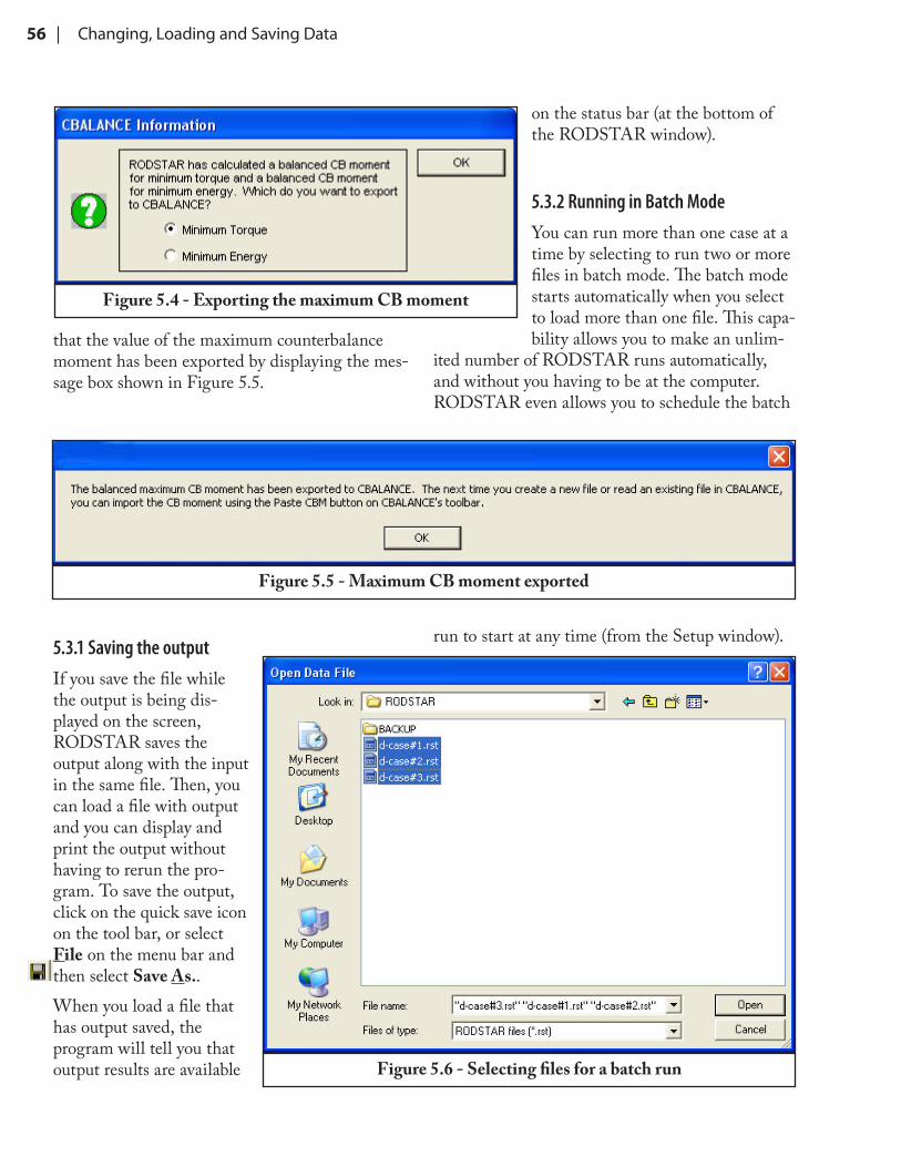
5 3 Running and Viewing the Output 54
5 3 1 Saving the output 56
5 3 2 Running in Batch Mode 56
5 4 Loading Data from Disk 58
5 4 1 Viewing Previously Saved Output 59
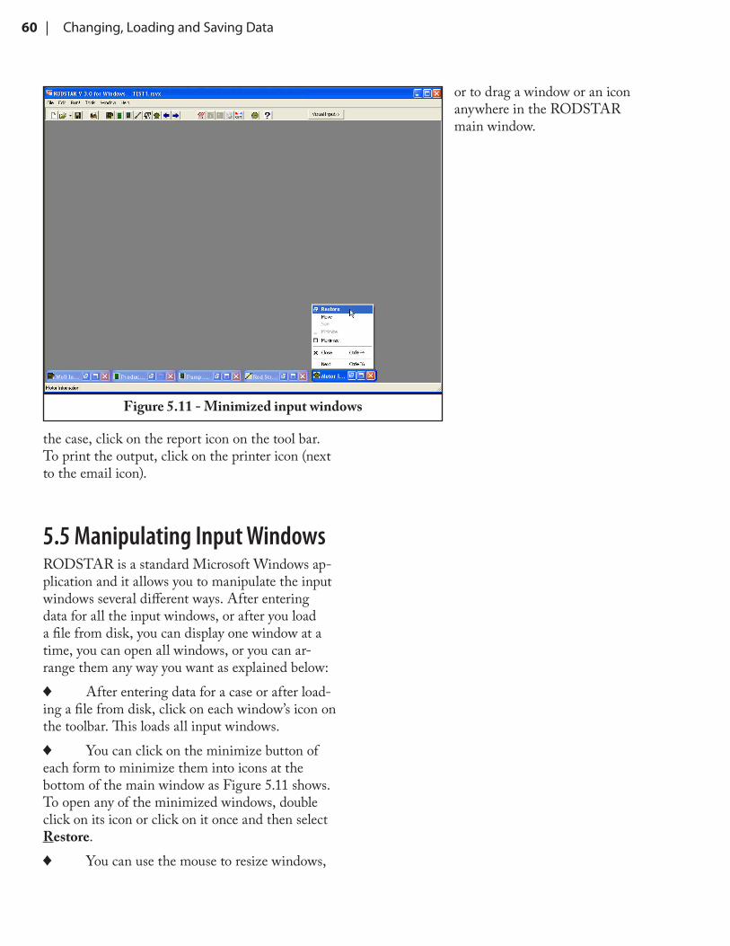
5 5 Manipulating Input Windows 60
6 Rod Pump System Design 61
6 1 Understanding RODSTAR’s Output 62
6 1 1 Dynamometer and Permissible Load Plots 62
6 1 2 Torque Plot 65
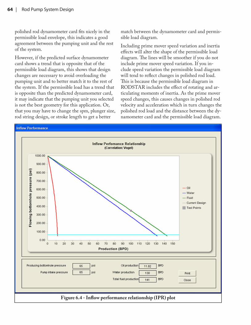
6 1 3 IPR Plot 65
6 1 4 Report 65
6 2 RODSTAR-D Output 70
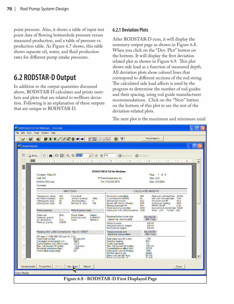
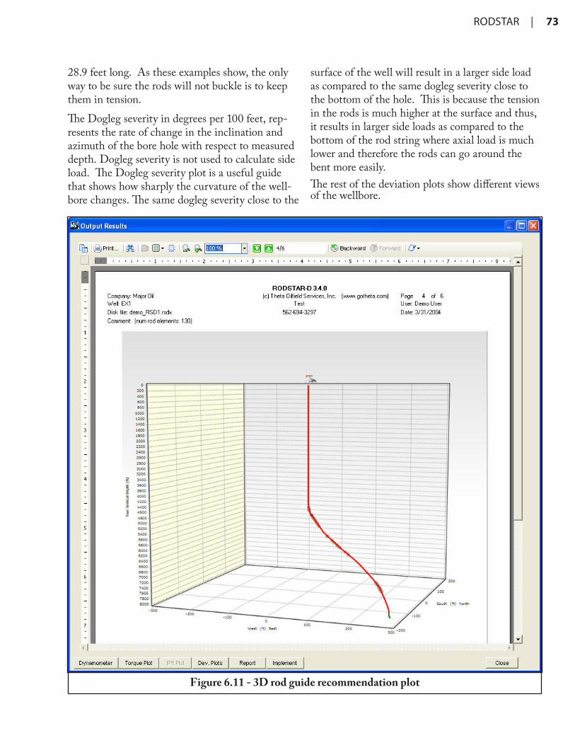
6 2 1 Deviation Plots 70
6 3 Rod Pump System Design Guidelines 74
6 3 1 Shallow, High Rate Well Simulation 74
6 3 2 Selecting the Target Production 75
6 3 3 Avoiding Rod Compression 75
6 3 4 Minimizing Power Consumption 75
6 3 5 Reducing Gearbox Torque 76
6 3 6 Using RODSTAR for Correct Equipment Sizing 76
6 3 7 Using RODSTAR for Diagnostic Analysis 77
6 3 8 Using RODSTAR-D for better Wellbore Designs 77
RODSTAR | v
Technical SupportTechnical Support for RODSTAR is provided by phone and e-mail to customers with a current An-nual Technical Support Agreement.The first year of technical support is provided free with the initial purchase of a license.Support for customers with an expired agreement is billed at $100/hour with a one-hour minimum per incident.Please include the Serial Number from your Senti-nel bitlock when contacting support.
Phone Support:Monday-Friday 8:00 AM - 4:00 PM PST.(562) 694-3297
RODSTAR™ for Windows is a powerful, easy-to-use rod pumping system simulator and design tool. With RODSTAR you can design new rod pumping installations or make changes to exist-ing rod pumping systems. It is a tool that you can use to compare pumping units, pumping speeds, plunger sizes, rods, motor types, etc. You can evaluate the effect of pump fillage, fluid level, or an out-of-balance unit. Also, you can study the effect of prime mover speed variation, stuffing box fric-tion, etc. RODSTAR also allows you to combine sophisticated rod pumping system modeling with inflow performance data for even more powerful capabilities.There are two versions of RODSTAR: ROD-STAR-D and RODSTAR-V. This manual applies to both for most items since the program’s user interface is practically identical except for an addi-tional input window in RODSTAR-D for entering the wellbore deviation survey. RODSTAR-D is primarily for rod pumping systems with deviated wellbores, while RODSTAR-V is for vertical well-bores (little to no deviation). When the program discusses “RODSTAR” it applies to both versions of the program. If there are differences between RODSTAR-D and V, the description in the manual will specify the program version (RODSTAR-D, or RODSTAR-V).RODSTAR is very easy to use, flexible, customiz-able, and fast. With a single click of the mouse you can access any input screen at any time. You can change an input by simply clicking on it, and when you have a question, simply press ! for context sensitive help for any input item. You can also take advantage of standard Windows features such as being able to copy the dynamometer, torque plots, or IPR plots to the clipboard and then paste them
in any other Windows document.By taking advantage of the program’s powerful “expert” knowledge you can save time and come up with better answers. This makes it possible to optimize rod string designs, find out the pumping speed and plunger size you need for a target pro-duction, etc. in minutes instead of hours. ROD-STAR makes it possible to get these answers even with little rod pumping expertise.
1.1 Program FeaturesRODSTAR remembers the information you type when you start a case from scratch. You can exit RODSTAR while in the middle of entering data for a new case, and RODSTAR will save the data you have entered so far. This works the same way if the program crashes. The next time you start RODSTAR, the program will ask you if you want to resume entering data. If so, you will be returned to the data entry window you were using when you left RODSTAR, with all the data you had entered already in place. RODSTAR contains data for all common pumps, rod sizes, rod grades, pump-ing units, tubing sizes, etc. Also, it “knows” when you need slim hole couplings or a thin wall pump, what rods fit in the tubing size you selected, the maximum recommended pumping speed for any system design, etc. RODSTAR can read well files created with ROD-DIAG™, XDIAG™ (Theta Oilfield Services, Inc.’s diagnostic computer programs) and XBAL™ (Theta Oilfield Services, Inc.’s pumping unit balancing program). RODSTAR can read all the data contained in a RODDIAG or XDIAG file, including the measured dynamometer card. This
2 | Introduction
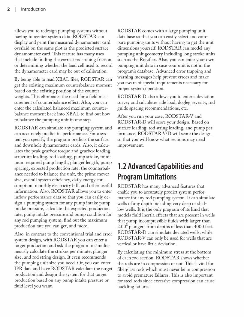
allows you to redesign pumping systems without having to reenter system data. RODSTAR can display and print the measured dynamometer card overlaid on the same plot as the predicted surface dynamometer card. This feature has many uses that include finding the correct rod-tubing friction, or determining whether the load cell used to record the dynamometer card may be out of calibration.By being able to read XBAL files, RODSTAR can get the existing maximum counterbalance moment based on the existing position of the counter-weights. This eliminates the need for a field mea-surement of counterbalance effect. Also, you can enter the calculated balanced maximum counter-balance moment back into XBAL to find out how to balance the pumping unit in one step.RODSTAR can simulate any pumping system and can accurately predict its performance. For a sys-tem you specify, the program predicts the surface and downhole dynamometer cards. Also, it calcu-lates the peak gearbox torque and gearbox loading, structure loading, rod loading, pump stroke, mini-mum required pump length, plunger length, pump spacing, expected production rate, the counterbal-ance needed to balance the unit, the prime mover size, overall system efficiency, daily energy con-sumption, monthly electricity bill, and other useful information. Also, RODSTAR allows you to enter inflow performance data so that you can easily de-sign a pumping system for any pump intake pump intake pressure, calculate the expected production rate, pump intake pressure and pump condition for any rod pumping system, find out the maximum production rate you can get, and more.Also, in contrast to the conventional trial and error system design, with RODSTAR you can enter a target production and ask the program to simulta-neously calculate the strokes per minute, plunger size, and rod string design. It even recommends the pumping unit size you need. Or, you can enter IPR data and have RODSTAR calculate the target production and design the system for that target production based on any pump intake pressure or fluid level you want.
RODSTAR comes with a large pumping unit data base so that you can easily select and com-pare pumping units without having to get the unit dimensions yourself. RODSTAR can model any pumping unit geometry including long stroke units such as the Rotaflex. Also, you can enter your own pumping unit data in case your unit is not in the program’s database. Advanced error trapping and warning messages help prevent errors and make you aware of special requirements necessary for proper system operation.RODSTAR-D also allows you to enter a deviation survey and calculates side load, dogleg severity, rod guide spacing recommendations, etc.After you run your case, RODSTAR-V and RODSTAR-D will score your design. Based on surface loading, rod string loading, and pump per-formance, RODSTAR-V/D will score the design so that you will know what sections may need improvement.
1.2 Advanced Capabilities and Program LimitationsRODSTAR has many advanced features that enable you to accurately predict system perfor-mance for any rod pumping system. It can simulate wells of any depth including very deep or shal-low wells. It is the only program of its kind that models fluid inertia effects that are present in wells that pump incompressible fluids with larger than 2.00” plungers from depths of less than 4000 feet. RODSTAR-D can simulate deviated wells, while RODSTAR-V can only be used for wells that are vertical or have little deviation.By calculating the minimum stress at the bottom of each rod section, RODSTAR shows whether the rods are in compression or not. This is vital for fiberglass rods which must never be in compression to avoid premature failures. This is also important for steel rods since excessive compression can cause buckling failures.
RODSTAR | 3
RODSTAR-V can model the effect of prime mover speed variation and pumping unit inertia and can accurately calculate electricity consump-tion and the monthly energy bill. Because ROD-STAR uses actual motor efficiency curves, the results are very accurate. You can use this capabil-ity to compare the energy consumption of systems with different rod designs, plunger sizes, or pump-ing unit types. RODSTAR’s Inflow Performance Relationship (IPR) capabilities allow you to select the IPR relationship you want RODSTAR to use (Vogel or Fetkovich), your can enter one to ten test points, and can integrate IPR and rod pumping system models to predict the maximum production rate possible, the fluid level and pump condition for a given pumping speed, or the target production for any fluid level or pump intake pressure you want.Because of all these features, RODSTAR has vir-tually no limitations and is the most advanced and easiest to use program of its kind.
1.3 Help SystemRODSTAR takes full advantage of Microsoft Windows to bring you state-of-the-art context-sensitive help for any input field by simply press-ing the ! key. Also, you can search help for any other item.
1.4 RODSTAR CD and Software SentinelThe RODSTAR program installation CD con-tains many compressed files that the installation program copies to the hard disk of your computer. Some of these are useful to know about. These are located in the same folder where you elected to install RODSTAR. The default is “C:\Program Files\Theta Enterprises\RODSTAR-V” or “C:\Program Files\Theta Enterprises\RODSTAR-D”.
RSWINV.Exe The program file for RODSTAR-V. It is the file that your Desktop Icon runs when you double-click it.
RSWIND.Exe The program file for RODSTAR-D. It is the file that your Desktop Icon runs when you double-click it.
RODSTAR.CDB Contains the costs for both rods and pumping units. Once you create this file by entering rod and pumping unit cost data, you can provide copies to other users in your company.
CUSTOM32.PUD This file contains the measured pumping unit information you entered in Setup. Once you create this file, you can distribute copies to other users in your company.
Files ending in .PUD The program’s pumping unit database. When updates are announced on our Website for new pumping units that have been added, you can download a zipped file that contains addi-tional PUD files to add to your folder.
Files beginning with demo_
Several files are in-cluded that are example cases to demonstrate the program functions.During installation, there are copies of these files placed in the folder used when opening case files.
Files ending in .RST Case files saved by RODSTAR release prior to 3.0.
Files ending in .RSVX Case files saved by RODSTAR-V.
4 | Introduction
Files ending in .RSDX Case files saved by RODSTAR-D.
Files ending in .RDG Case files saved by RODDIAG.
Files ending in .XDG Case files saved by XDIAG.
Files ending in .CBLX or .XBLX
Case files saved by XBAL
SENTINEL.INI For installations using a Network license, this file is located in the program folder on the client PC and has the name or IP address of the license server being used.
The RODSTAR program is protected and cannot run without a software sentinel supplied by Theta Oilfield Services, Inc.. See Chapter 2 for details on how to install the software sentinel.
RODSTAR | 5
2 Software Installation
Before you install the program, make sure you have the hardware and software you need to run RODSTAR for Windows.
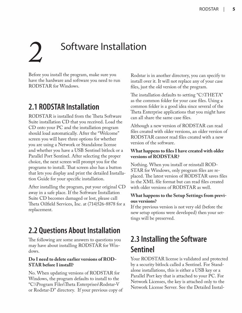
2.1 RODSTAR InstallationRODSTAR is installed from the Theta Software Suite installation CD that you received. Load the CD onto your PC and the installation program should load automatically. After the “Welcome” screen you will have three options for whether you are using a Network or Standalone license and whether you have a USB Sentinel bitlock or a Parallel Port Sentinel. After selecting the proper choice, the next screen will prompt you for the programs to install. That screen also has a button that lets you display and print the detailed Installa-tion Guide for your specific installation. After installing the program, put your original CD away in a safe place. If the Software Installation Suite CD becomes damaged or lost, please call Theta Oilfield Services, Inc. at (714)526-8878 for a replacement.
2.2 Questions About InstallationThe following are some answers to questions you may have about installing RODSTAR for Win-dows.Do I need to delete earlier versions of ROD-STAR before I install?No. When updating versions of RODSTAR for Windows, the program defaults to install to the “C:\Program Files\Theta Enterprises\Rodstar-V or Rodstar-D” directory. If your previous copy of
Rodstar is in another directory, you can specify to install over it. It will not replace any of your case files, just the old version of the program.The installation defaults to setting “C:\THETA” as the common folder for your case files. Using a common folder is a good idea since several of the Theta Enterprise applications that you might have can all share the same case files.Although a new version of RODSTAR can read files created with older versions, an older version of RODSTAR cannot read files created with a new version of the software.What happens to files I have created with older versions of RODSTAR?Nothing. When you install or reinstall ROD-STAR for Windows, only program files are re-placed. The latest version of RODSTAR saves files in the XML file format but can read files created with older versions of RODSTAR as well.What happens to the Setup Settings from previ-ous versions? If the previous version is not very old (before the new setup options were developed) then your set-tings will be preserved.
2.3 Installing the Software SentinelYour RODSTAR license is validated and protected by a security bitlock called a Sentinel. For Stand-alone installations, this is either a USB key or a Parallel Port key that is attached to your PC. For Network Licenses, the key is attached only to the Network License Server. See the Detailed Instal-
6 | Program Installation
lation Guide that is available for printing from the Software Installation Suite CD.RODSTAR communicates with the sentinel and although the program can be copied, it will not operate without a sentinel supplied by Theta Oil-field Services, Inc.. If the sentinel is not installed correctly, the pro-gram will warn you that the sentinel does not ap-pear to be connected. If this occurs, make sure the sentinel in properly installed and the connection is not loose. If the sentinel is properly installed but is not working, it may have been damaged. Frequent plugging and unplugging, and static electricity can damage the sentinel. If this occurs, contact Theta Oilfield Services Inc. to determine if you need a replacement. Do not discard the damaged sentinel. Even if it is damaged, you must return it to Theta Oilfield Services, Inc. before a replacement can be sent out. When RODSTAR first starts, it reads and displays the serial number of your sentinel on the opening screen.Theta Oilfield Services, Inc. uses Sentinel “Super-Pro” for software protection. If you use software sentinels from other vendors, you may be able to cascade Sentinels as long as the LPT1 port has only one Sentinel “C” on it. The rest of the Sen-tinels must be a different type. If you have one or more Sentinel “PRO” and one Sentinel “C”, then plug the Sentinel “C” at the end of the Sentinel PROs or SuperPros. USB type Sentinels can be plugged into any available USB port or hub on the PC.
RODSTAR | 7
3 Starting and Setting Up RODSTAR
3.1 Starting RODSTARThe RODSTAR installation program will put an Icon on your Desktop and an entry in your Start Programs for access to RODSTAR. To start the program, simply double-click on its icon.You can also start RODSTAR from the File Manager by double clicking on RSWIND.EXE for RODSTAR-D, or RSWINV.EXE for ROD-STAR-V. Also, the Windows File Manager allows you to associate files with applications. When you associate a file with an application, you open the file and start the application at the same time. For example, to associate RODSTAR-D files (with an “.RSDX” file name extension) with RSWIND.EXE, do the following:1. From the File man-
ager, go to a direc-tory that contains RODSTAR files and double-click on one of these files.
2. If the file is not already associated with RODSTAR-D, windows will let you know and ask you to select the program from a list. Make sure this option is selected and click on the OK button.
3. Click on Browse, go to the directory where RSWIND.EXE resides (typi-
cally, it will be in C:\Program Files\Theta Enterprises\RODSTAR-D, and double click on it.
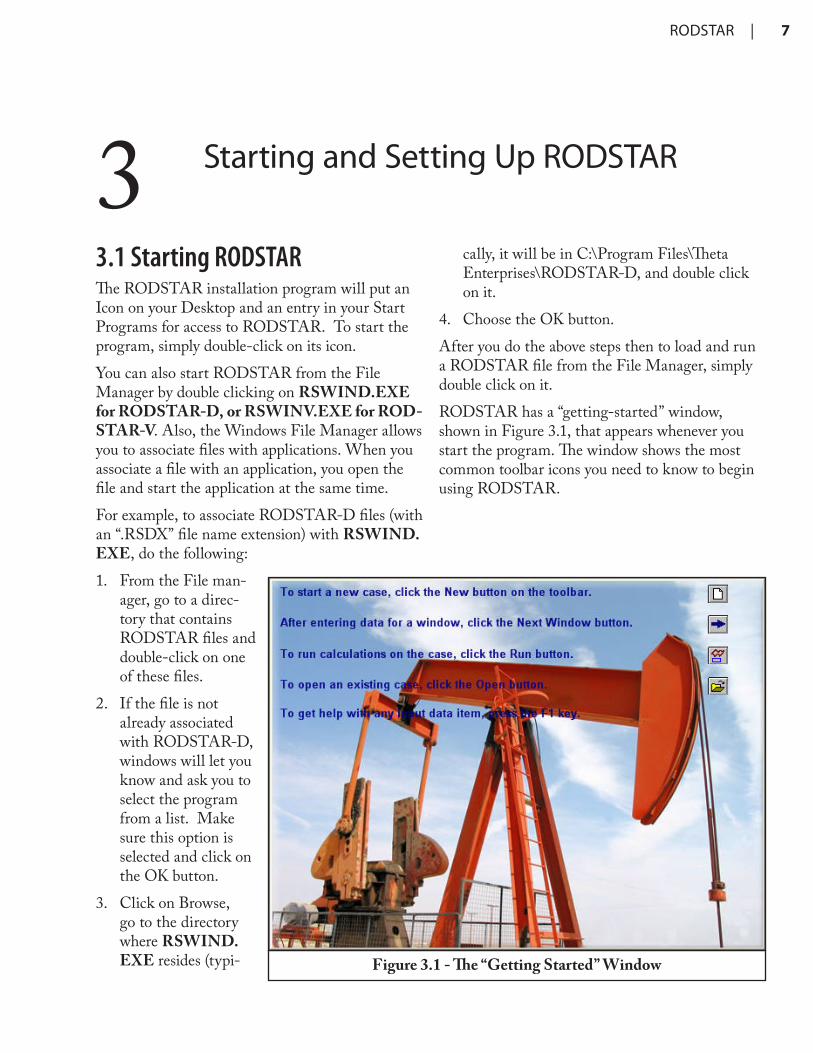
4. Choose the OK button.After you do the above steps then to load and run a RODSTAR file from the File Manager, simply double click on it.RODSTAR has a “getting-started” window, shown in Figure 3.1, that appears whenever you start the program. The window shows the most common toolbar icons you need to know to begin using RODSTAR.
Figure 3.1 - The “Getting Started” Window
8 | Starting and Setting Up RODSTAR
3.2 Exiting RODSTARTo exit RODSTAR, double click on its Control-menu box (upper left hand corner) or select File and then Exit. Another way to exit RODSTAR is to press A+ $. Before exiting RODSTAR make sure you have stored your data to disk (RODSTAR asks you if you want to save the data when you exit, if you have changed your data since the last time you saved it). Otherwise it will be lost.
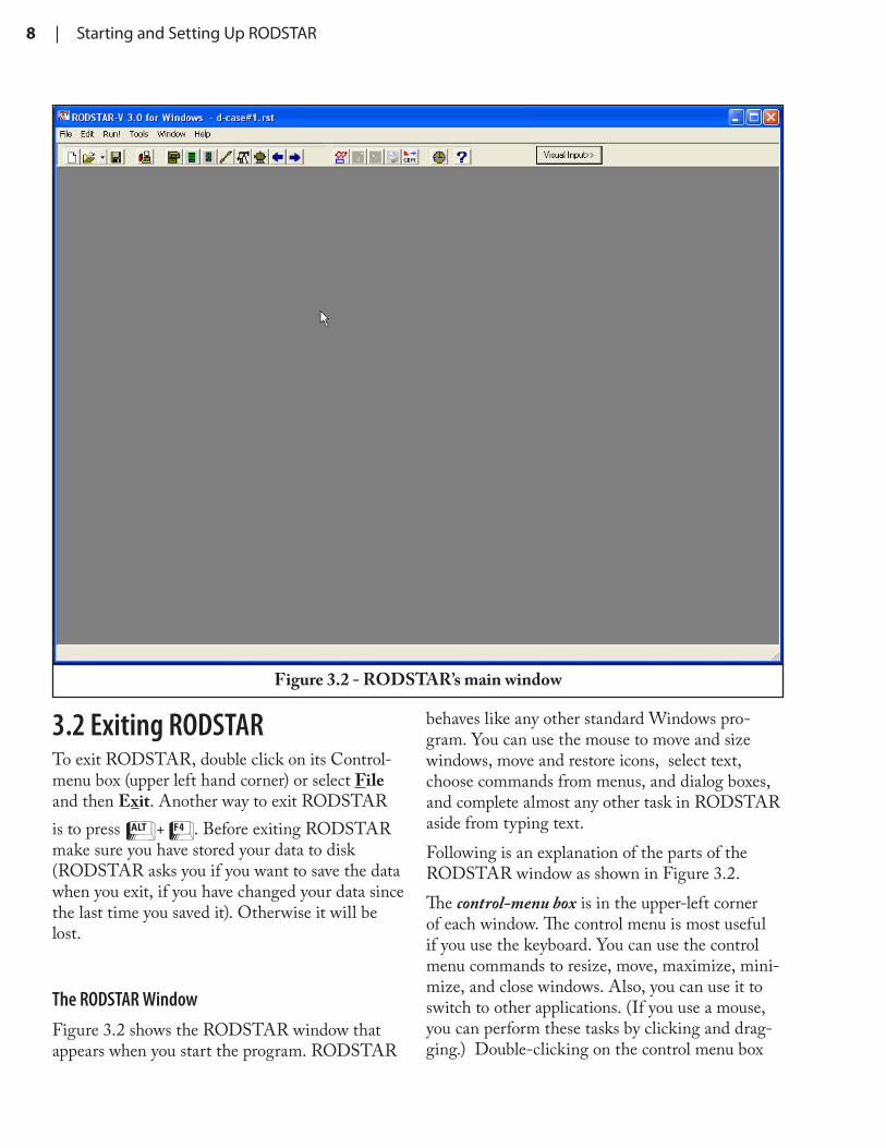
The RODSTAR Window Figure 3.2 shows the RODSTAR window that appears when you start the program. RODSTAR
behaves like any other standard Windows pro-gram. You can use the mouse to move and size windows, move and restore icons, select text, choose commands from menus, and dialog boxes, and complete almost any other task in RODSTAR aside from typing text.Following is an explanation of the parts of the RODSTAR window as shown in Figure 3.2.The control-menu box is in the upper-left corner of each window. The control menu is most useful if you use the keyboard. You can use the control menu commands to resize, move, maximize, mini-mize, and close windows. Also, you can use it to switch to other applications. (If you use a mouse, you can perform these tasks by clicking and drag-ging.) Double-clicking on the control menu box
Figure 3.2 - RODSTAR’s main window
RODSTAR | 9
closes RODSTAR.The title bar shows the name of the application and the name of the file currently in memory. If more than one window is open, the title bar for each active window (the one that you are working with) is a different color or intensity than the other title bars.The menu bar lists the available menus. A menu contains a list of commands, or actions, you can carry out with RODSTAR. For example, click on the Help menu to see a list of helpful choices.The Minimize button reduces RODSTAR to an icon. After you minimize RODSTAR, you can reopen it by double clicking on the RODSTAR icon at the bottom of your screen.The Maximize button causes the RODSTAR win-dow to fill the entire screen. After you maximize the RODSTAR window, the maximize button shows a double box and is called the restore but-ton. Clicking on the restore button re-sizes the RODSTAR window to the size it was before you maximized it.Using the mouse you can resize RODSTAR’s main windows. When you resize RODSTAR’s window to a size smaller than required to display all information, it will display vertical or horizon-tal scroll bars as necessary. You can use these scroll bars with the mouse to view unseen portions of entry windows that do not fit in the allotted space.The Close button causes RODSTAR to exit. It’s easier to click the Close button once than to select Exit from the File menu.The Status bar shows useful messages during data entry, when you load a case from disk or when you point to a toolbar icon.The toolbar gives you quick access to menu com-mands using your mouse. When you first load RODSTAR, only some of the buttons on the toolbar are active. When you enter data or read a
file from disk, then the print button and all the buttons that correspond to input windows become active. If you load a file that contains output then the report icon also activates. Otherwise, if the file contains only input then the report icon re-mains inactive until you run the case. For a quick reminder of what each toolbar button does, simply place the mouse pointer on it. A small message box called a “tool tip” appears that tells you what the toolbar icon does (see Figure 3.2). Also, the status bar shows more information about the same tool bar item.Following is a more detailed explanation of each button on the toolbar from left to right:New file - This is the first button on the toolbar and shows a picture of a blank page. Click on this button to start entering data for a new case.Open file - This is the second button on the toolbar and shows the standard open file icon used by most Windows programs. Click on this button to read a RODSTAR, RODDIAG, or XDIAG file that was previously stored on disk.Save file - This is the third item on the toolbar and shows a picture of a diskette. Click here to save the data in memory to disk. If this is the first time you are saving this case, RODSTAR asks for a new file name. After you save a file, or after you load a file from disk and make changes to it, click on this button to quick-save the data under the same file name. To save it under a different file name click on File on the menu bar and then select Save As....Setup - This is the fourth item on the toolbar. Click here to see RODSTAR’s Setup window. This allows you to specify inputs and preferences that normally do not change often such as: your company name, electricity cost, units of measure, standard sucker rod length, custom sucker grades, measured pumping unit data, pumping unit and sucker rod cost, batch run options, printed report
Figure 3.3 - RODSTAR’s toolbar
10 | Starting and Setting Up RODSTAR
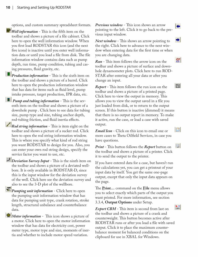
options, and custom summary spreadsheet formats.Well information - This is the fifth item on the toolbar and shows a picture of a file cabinet. Click here to open the well information window. When you first load RODSTAR this icon (and the next five icons) is inactive until you enter well informa-tion data or until you load a file from disk. The file information window contains data such as pump depth, run time, pump condition, tubing and cas-ing pressures, fluid gravity, etc.Production information - This is the sixth item on the toolbar and shows a picture of a barrel. Click here to open the production information window that has data for items such as fluid level, pump intake pressure, target production, IPR data, etc. Pump and tubing information - This is the sev-enth item on the toolbar and shows a picture of a downhole pump . Click here to see data for tubing size, pump type and size, tubing anchor depth, rod-tubing friction, and fluid inertia effects.Rod string information - This is item eight on the toolbar and shows a picture of a sucker rod. Click here to open the rod string information window. This is where you specify what kind of rod string you want RODSTAR to design for you. Also, you can enter your own rod string design, specify the service factor you want to use, etc.Deviation Survey Input - This is the ninth item on the toolbar and shows a picture of a deviated well-bore. It is only available in RODSTAR-D, since this is the input window for the deviation survey of the well. Click here see the deviation survey and also to see the 3-D plot of the wellbore.Pumping unit information - Click here to open the pumping unit information window that has data for pumping unit type, crank rotation, stroke length, structural unbalance and counterbalance data.Motor information - This icon shows a picture of a motor. Click here to open the motor information window that has data for electricity cost, power meter type, motor type and size, moments of iner-tia and whether to include motor speed variation.
Previous window - This icon shows an arrow pointing to the left. Click it to go back to the pre-vious input window.Next window - This shows an arrow pointing to the right. Click here to advance to the next win-dow when entering data for the first time or when you are changing data.Run - This item follows the arrow icon on the toolbar and shows a picture of surface and down-hole dynamometer plots. Click here to run ROD-STAR after entering all your data or after you change an input.Report - This item follows the run icon on the toolbar and shows a picture of a printed page. Click here to view the output in memory. This allows you to view the output saved in a file you just loaded from disk, or to return to the output screen. If this button is inactive (dimmed) it means that there is no output report in memory. To make it active, run the case, or load a case with saved output.Email Icon - Click on this icon to email one or more cases to Theta Oilfield Services, in case you have questions.Print - This button follows the Report button on the toolbar and shows a picture of a printer. Click it to send the output to the printer.If you have entered data for a case, but haven’t run the calculations yet, you can get a printout of your input data by itself. You get the same one-page output, except that only the input data appears on the page.The Print… command on the File menu allows you to select exactly which parts of the output you want printed. For more information, see section 3.3.4, Output Options under Setup.Export CBM - This item is second from last on the toolbar and shows a picture of a crank and counterweight. This button becomes active after RODSTAR runs or after you load a file with saved output. Click it to place the maximum counter-balance moment for balanced conditions on the clipboard for use in XBAL for Windows.
RODSTAR | 11
Help - This is the last item on the toolbar and shows a picture of a question mark. Click this button at any time to get help.
3.3 Setting up RODSTARClick on the Setup button on the toolbar to open RODSTAR’s Setup window. Another way to access Setup is to open the Tools menu and then select RODSTAR Setup. This window as shown in Figure 3.5 allows you to enter items that do not normally change from run to run. Also, Setup allows you to customize RODSTAR by entering your company name, default electricity cost, custom rod grades, measured pumping units, rod and pumping unit cost data, and a lot more. The measured pumping unit data you enter is saved in the CUSTOM32.PUD file in the program directory; the cost data you enter for rods and pumping units is saved the RODSTAR.CDB file in the program directory. RODSTAR stores all other information you enter in Setup in the registry.
3.3.2 General setup options
Measurement UnitsFor measurement units you can select English, Canadian, or Metric/SI. English units are mainly used in the USA and South America. If you select this option
RODSTAR will ask for pump depth in feet, pro-duction rate in BFPD, plunger and rod diameters in inches, etc. The “Canadian” option provides you with the common mix of English and Metric units used in Canada. The “Metric/SI” option will cause RODSTAR to use Metric/SI units for most inputs. Regardless of the units you select, you can press @ while entering numeric data to convert from one system of units to the other. When you press @ to convert units, the background of the input field box changes color from light blue to
Figure 3.4 - RODSTAR’s Setup window
Figure 3.5 - Help for RODSTAR’s setup
12 | Starting and Setting Up RODSTAR
light green.
Show Visual Input WindowIf you uncheck this checkbox you will deactivate the Visual Input feature in RODSTAR. This feature is accessed through the toolbar or windows tab of the menu bar. The Visual Input Window allows you to select an input parameter by click-ing on that part of a graphical representation of the well. For more information on the visual input feature see section 5.1.
Save XDIAG Imported Dyno Card to RODSTAR FileWhen opening an XDIAG file in RODSTAR, the measured surface dynamometer card is shown in the surface dynamometer card graph of the output report. This allows you to perform a history match to determine the amount of friction that is in the well. Check this checkbox if you would like the measured surface dynamometer card imported from the XDIAG file to be saved to the ROD-STAR file. This will allow you to use the ROD-STAR file in the future to run in XDIAG if you do not locate the original XDIAG file.
Exit Program if IdleThis feature was primarily designed for network li-censes, but can be utilized to save your work if you are away from your computer for a set amount of time. If the checkbox is checked, the program will exit after the set amount of time. In the case of the network license, this will release the license for another user to use. This avoids the problem where the license may be locked onto that computer because the user left the software running but left there computer for an extended amount of time. There is also a checkbox to save your work before the program exits in this fashion. This will allow you to retain what you have worked on before the program exits.
3.3.3 Defaults, Limits, and Rod Guide SetupThe “Defaults” input window in Setup for ROD-STAR-V is shown in Figure 3.6. Here, ROD-STAR allows you customize the default informa-tion used by the program when you begin entering data for a new case. You can also change the rod stress loading limits used by RODSTAR in a steel or fiberglass rod design, so that RODSTAR will use larger rods rather than exceed the loading limits you specify. Any of the following items can be customized: • Casing pressure• Company name• Electricity cost• IPR correlation• Motor type• Oil gravity• Plunger size• Pump condition• Pump efficiency• Pump fillage• Pump load adjustment• Run time• Standard steel sucker rod length• Steel rod service factor• Stuffing box friction• Tubing pressure• User name• Water cut• Water specific gravityThe program uses the standard steel sucker rod length (typically 25 or 30 ft.) to calculate steel rod string section lengths that are evenly divisible by it. This works whenever RODSTAR designs the rods string (when RODSTAR calculates a steel rod string taper design, whether for a steel rod string, or a tapered steel rod section beneath a fiberglass.)
RODSTAR | 13
For Corod rod strings, RODSTAR ignores this number. For fiber-glass rods, the pro-gram uses the standard length of 37.5 feet. Be-low the defaults, you can set the rod loading threshold for steel and fiberglass sucker rods. When RODSTAR designs a rod string it begins with a single taper using the small-est diameter set by the user. Once the tapers are set, the program balances the rod string then the program checks the rod loading against these values. If the rod loading is more than what is entered in these fields, it will redesign the string with stronger rods, rebalance the string, and check the loading against these values again. This routine will continue until either the rod loading is equal to or less than the values entered here, or until the strongest rods are used.Here you will also see a checkbox which is labeled “Use all diameters when de-signing Rod String”. RODSTAR will use a single taper in design-ing the rod string if it will satisfy the lifting requirement. In cases where the loading is low enough to war-rant a single taper design, checking this checkbox will force RODSTAR to use a tapered design with all the diameters be-tween and including the max and min di-
ameters set by the user. This feature was designed for users that use only tapered rod string designs.Figure 3.6d shows the Defaults input window for RODSTAR-D. Here, in addition to the default values and rod stress loading limits discussed above, you can also specify the type of rod guides you want to use. There are two main options to the rod guide selection, you may enter the rod guide
Figure 3.6d - Setting up default quantities for RODSTAR-D
Figure 3.6 - Setting up default quantities for RODSTAR-V
14 | Starting and Setting Up RODSTAR
Print toolbar button. You can choose from among the following:
♦ Cover PageThis option will generate a cover page for the output report which contains all your company information and the recipient’s information. You can edit what information is on this page in the setup window under defaults. The user information that is set in defaults (such as user name and company name) is your information. The items that are labeled as “Second Company” before the item in defaults are for the recipient’s information. For example, “Second Company Name” is the name of the recipient’s company. To add additional information to the cover page, you may go to the well information window and click the “+” button next to the comment entry field. You can also edit the cover page after the case is ran by clicking the “+” button on the bottom of the output report window. After clicking the “+” button, you will see the main cover page editing window. You can insert items such as the well information comment from the well information window or the rod string information by clicking those respective buttons in this window.
information manually or have RODSTAR-D design the rod guides for you. To have the pro-gram design the rod guides for you, the preferred rod guide must be selected from the option on the setup window. Once you select a guide for ROD-STAR-D to use, you can specify the amount of side loading each rod guide is designed to inhibit, and the amount of friction that the rod guides have against the tubing. A friction coefficient value of 0.2 models the friction between bare steel rods against steel tubing. To determine the friction value to use for your selected rod guides, consult the manufacturer. The manufacturer should be able to tell you, in reference to the steel rod friction value, what the rod guide friction value is for your rod guides. The manufacturer may tell you the rod guides have 2 times the amount of friction as bare steel on steel tubing, then you would enter 2 * 0.2 which is 0.4.You can also specify the maximum and minimum number of rod guides per rod. When RODSTAR-D recommends the rod guide placement, it will use the minimum number of rods per guide if the calculated number is less than the minimum num-ber. The same is true for the maximum rod guides per rod. If the calculated number of guides per rod is more than the maximum value, then the recom-mendation will use the maximum number.
3.3.4 Output OptionsRODSTAR gives you full control over what is shown on the printed output. Using the Output Options tab in Setup, shown in Figure 3.7, you can select the items you want included on the output. The options you select here are the items printed by default when you select Print… from the File menu, or use the Figure 3.7 - Selecting output options
RODSTAR | 15
♦ Scoring PageThis option will generate a scoring page for the output report which displays the overall score of the design in basic letter grade format. If there are any areas of concern for the design which may have caused a low score, the software will display the issues here and recommend solutions to the problems. If the system receives a good score without recommendations, then the scoring page will not be displayed.The system design is scored on the following items:• Balanced Gearbox Loading
The maximum gearbox loading when the unit is balanced. It is important to note that this score is based on a balanced unit. If your unit is not balanced, the actual loading will not correspond to the loading percentage displayed in this section. Be sure to observe the actual loading of the gearbox if the unit has not been balanced.• Maximum Rod Loading
This score is based on the maximum rod loading of all tapers of the rod string. For example, if the rod string has three tapers, and each taper has a rod loading of 90%, 99%, 47% respectively, then the score will be based on the 99% loading of taper two. If the loading is low, the score will be lowered slightly because the rod string is over-sized or over-designed. If the rod loading is overloaded then the score is lowered severely as that will lead to premature failure in the rod string.• Structure Loading
The structure loading score is based on the peak loading at the surface on the polished rod (peak polished rod loading). This load is compared to the structural rating of the pumping unit to calculate the structural loading. Similar to the rod loading score, the structure loading score is lowered slightly if the unit is oversized and lowered severely if the unit is overloaded.• System Efficiency
This score is dependent on pump depth and production rate. This is because the maximum
efficiency fluctuates depending on the depth and production. To further explain, a very deep well requires a lot of energy to lift the rod string. Comparing the energy required to lift the rod string to the energy required to lift the fluid (at the given production rate) the maximum efficiency drops. Based on this principle, the scoring of the efficiency is adjusted so that the grade is calculated on the appropriate scale.• Bottom Minimum Stress
This refers to the bottom minimum stress of the sucker rods. This score is not affected by the bottom minimum stress of sinker rods or sinker bars. If the bottom minimum stress on the sucker rods is negative, the score is lowered because compression in the sucker rods may cause buckling. Buckling rods can cause tubing leaks and premature failures. If the stress on the bottom minimum stress of the sucker rods is high, the score is lowered slightly. This is because the sinker bars are too long, which cause the high tension on the bottom of the sucker rods, and the well requires more energy to lift throughout the cycle than necessary.• Minimum Polished Rod Loading
The minimum polished rod load is used to determine this score. If the minimum load on the polished rod is negative, the score is lowered because the rod string will float. A floating rod string is where the pumping unit begins the down-stroke and, due to friction or speed of the pumping unit, the rod string doesn’t follow carrier bar and separates from the pumping unit. This causes a severe problem where the system will suffer a shock at the bottom of the stroke as the pumping unit begins the upstroke and the rod string comes down on the carrier bar. The effect is like a very large hammer, with the weight of the rod strong and fluid over the plunger, hitting the top of the carrier bar on each stroke.
♦ Input data and calculated resultsThis option prints one page showing all the input data and the results of the calculations, as well as miniature predicted dynamometer and torque
16 | Starting and Setting Up RODSTAR
♦ Measured Deviation SurveySelecting this option will add pages which show the entered deviation survey. This is helpful if you need to send the results to a customer or coworker that does not have the digital file. If they need to recreate the case, the deviation survey is included with the rest of the well information.
♦ Overlay actual (measured) dynamometer cardIf you load a RODDIAG or XDIAG case into RODSTAR, the program can plot the surface dynamometer card that was stored in the ROD-DIAG or XDIAG file on the same plot as the predicted dynamometer card.
♦ Omit Dyno cards and Torque Plot from calculate results page viewingSelect this option if you would like to remove the dynamometer cards and torque plot graphs from the calculated results page. No other data will be removed from the calculated results page other than these graphs from the bottom of the page.
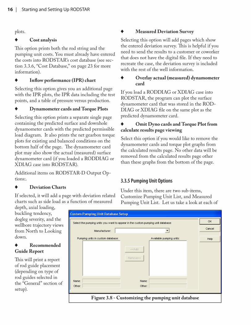
3.3.5 Pumping Unit Options
Under this item, there are two sub-items, Customize Pumping Unit List, and Measured Pumping Unit List. Let us take a look at each of
plots. ♦ Cost analysis
This option prints both the rod string and the pumping unit costs. You must already have entered the costs into RODSTAR’s cost database (see sec-tion 3.3.6, “Cost Database,” on page 23 for more information).
♦ Inflow performance (IPR) chartSelecting this option gives you an additional page with the IPR plots, the IPR data including the test points, and a table of pressure versus production.
♦ Dynamometer cards and Torque PlotsSelecting this option prints a separate single page containing the predicted surface and downhole dynamometer cards with the predicted permissible load diagram. It also prints the net gearbox torque plots for existing and balanced conditions on the bottom half of the page. The dynamometer card plot may also show the actual (measured) surface dynamometer card (if you loaded a RODDIAG or XDIAG case into RODSTAR). Additional items on RODSTAR-D Output Op-tions:.
♦ Deviation ChartsIf selected, it will add a page with deviation related charts such as side load as a function of measured depth, axial loading, buckling tendency, dogleg severity, and the wellbore trajectory views from North to Looking down.
♦ Recommended Guide ReportThis will print a report of rod guide placement (depending on type of rod guides selected in the “General” section of setup).
Figure 3.8 - Customizing the pumping unit database
RODSTAR | 17
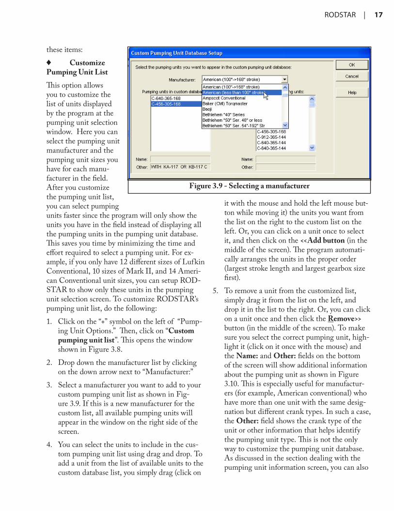
these items: ♦ Customize
Pumping Unit ListThis option allows you to customize the list of units displayed by the program at the pumping unit selection window. Here you can select the pumping unit manufacturer and the pumping unit sizes you have for each manu-facturer in the field. After you customize the pumping unit list, you can select pumping units faster since the program will only show the units you have in the field instead of displaying all the pumping units in the pumping unit database. This saves you time by minimizing the time and effort required to select a pumping unit. For ex-ample, if you only have 12 different sizes of Lufkin Conventional, 10 sizes of Mark II, and 14 Ameri-can Conventional unit sizes, you can setup ROD-STAR to show only these units in the pumping unit selection screen. To customize RODSTAR’s pumping unit list, do the following:1. Click on the “+” symbol on the left of “Pump-
ing Unit Options.” Then, click on “Custom pumping unit list”. This opens the window shown in Figure 3.8.
2. Drop down the manufacturer list by clicking on the down arrow next to “Manufacturer:”
3. Select a manufacturer you want to add to your custom pumping unit list as shown in Fig-ure 3.9. If this is a new manufacturer for the custom list, all available pumping units will appear in the window on the right side of the screen.
4. You can select the units to include in the cus-tom pumping unit list using drag and drop. To add a unit from the list of available units to the custom database list, you simply drag (click on
it with the mouse and hold the left mouse but-ton while moving it) the units you want from the list on the right to the custom list on the left. Or, you can click on a unit once to select it, and then click on the <<Add button (in the middle of the screen). The program automati-cally arranges the units in the proper order (largest stroke length and largest gearbox size first).
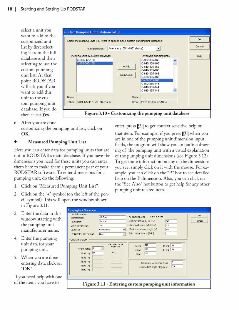
5. To remove a unit from the customized list, simply drag it from the list on the left, and drop it in the list to the right. Or, you can click on a unit once and then click the Remove>> button (in the middle of the screen). To make sure you select the correct pumping unit, high-light it (click on it once with the mouse) and the Name: and Other: fields on the bottom of the screen will show additional information about the pumping unit as shown in Figure 3.10. This is especially useful for manufactur-ers (for example, American conventional) who have more than one unit with the same desig-nation but different crank types. In such a case, the Other: field shows the crank type of the unit or other information that helps identify the pumping unit type. This is not the only way to customize the pumping unit database. As discussed in the section dealing with the pumping unit information screen, you can also
Figure 3.9 - Selecting a manufacturer
18 | Starting and Setting Up RODSTAR
select a unit you want to add to the customized unit list by first select-ing it from the full database and then selecting to use the custom pumping unit list. At that point RODSTAR will ask you if you want to add this unit to the cus-tom pumping unit database. If you do, then select Yes.
6. After you are done customizing the pumping unit list, click on OK.
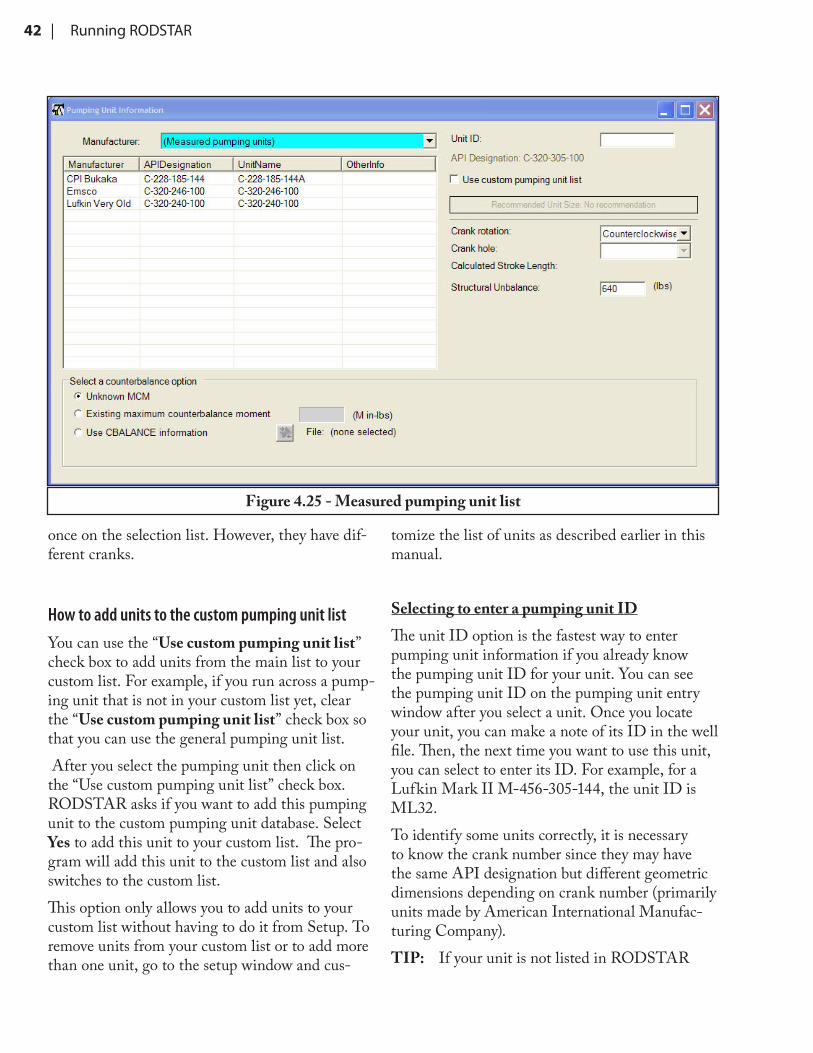
♦ Measured Pumping Unit ListHere you can enter data for pumping units that are not in RODSTAR’s main database. If you have the dimensions you need for these units you can enter them here to make them a permanent part of your RODSTAR software. To enter dimensions for a pumping unit, do the following:1. Click on “Measured Pumping Unit List”.2. Click on the “+” symbol (on the left of the pen-
cil symbol). This will open the window shown in Figure 3.11.
3. Enter the data in this window starting with the pumping unit manufacturer name.
4. Enter the pumping unit data for your pumping unit.
5. When you are done entering data click on “OK”.
If you need help with one of the items you have to
enter, press ! to get context sensitive help on that item. For example, if you press ! when you are in one of the pumping unit dimension input fields, the program will show you an outline draw-ing of the pumping unit with a visual explanation of the pumping unit dimensions (see Figure 3.12). To get more information on any of the dimensions you see, simply click on it with the mouse. For ex-ample, you can click on the “P” box to see detailed help on the P dimension. Also, you can click on the “See Also” hot button to get help for any other pumping unit related item.
Figure 3.10 - Customizing the pumping unit database
Figure 3.11 - Entering custom pumping unit information
RODSTAR | 19
3.3.6 Rod Grade Options
Entering Custom Rod GradesTo enter a rod grade that is not in the program’s database, do the follow-ing:1. From the setup win-
dow, click on “Cus-tom Rod Grades.”
2. To add a new rod grade, click on the “+” button (to the left of the pencil icon). This opens up a new window where you can enter the name of the rod you want to add, the tensile strength, and the stress analysis method you want RODSTAR to use for this rod as shown in Figure 3.13.
3. You can also specify that this is a sinker bar by clicking on the “Sinker bar” option at the lower left hand corner of this window.
4. Enter the rest of the information for the rod you want to add and then click on the “OK” button.
RODSTAR allows you to select any of the available stress analysis methods. Once you enter a special rod grade to the program, it becomes part of the program’s equipment database and it works exactly the same way as RODSTAR’s built-in rod grades.For example, once you
enter a special rod grade, you can enter cost infor-mation for it, and you can select it from the same rod grade menu that RODSTAR uses for the built-in rod grades.The modify (Pencil Icon) and delete (“X” Icon) options allow you to change or erase custom rod
Figure 3.12 - Custom pumping unit help
Figure 3.13 - Entering custom rod grade information
20 | Starting and Setting Up RODSTAR
grades you have already entered.
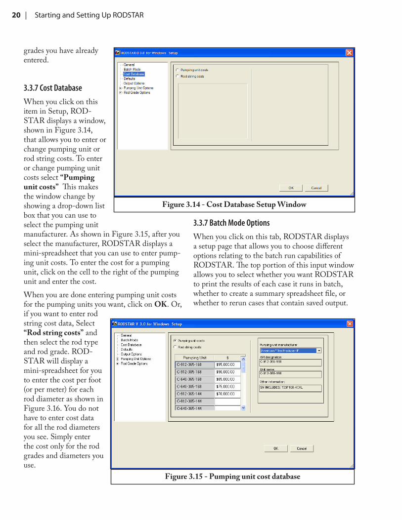
3.3.7 Cost DatabaseWhen you click on this item in Setup, ROD-STAR displays a window, shown in Figure 3.14, that allows you to enter or change pumping unit or rod string costs. To enter or change pumping unit costs select “Pumping unit costs” This makes the window change by showing a drop-down list box that you can use to select the pumping unit manufacturer. As shown in Figure 3.15, after you select the manufacturer, RODSTAR displays a mini-spreadsheet that you can use to enter pump-ing unit costs. To enter the cost for a pumping unit, click on the cell to the right of the pumping unit and enter the cost.When you are done entering pumping unit costs for the pumping units you want, click on OK. Or, if you want to enter rod string cost data, Select “Rod string costs” and then select the rod type and rod grade. ROD-STAR will display a mini-spreadsheet for you to enter the cost per foot (or per meter) for each rod diameter as shown in Figure 3.16. You do not have to enter cost data for all the rod diameters you see. Simply enter the cost only for the rod grades and diameters you use.
3.3.7 Batch Mode OptionsWhen you click on this tab, RODSTAR displays a setup page that allows you to choose different options relating to the batch run capabilities of RODSTAR. The top portion of this input window allows you to select whether you want RODSTAR to print the results of each case it runs in batch, whether to create a summary spreadsheet file, or whether to rerun cases that contain saved output.
Figure 3.14 - Cost Database Setup Window
Figure 3.15 - Pumping unit cost database
RODSTAR | 21
Also, it lets you choose what action to take when you load a file that con-tains custom rod grades as shown in Figure 3.17. For example, if you want to update the setup informa-tion with the data in the file, then select the option “Update Setup with file’s information.”If you check the Make Printouts check box, RODSTAR will print out every case you run in batch. If you check the Create summary spreadsheet check box, RODSTAR will summarize the results of all the files you run in batch in a Excel spreadsheet file. If you select the option “View spreadsheet file”, after you run several cases with the batch process, the program will automatically create an Excel spreadsheet and will load it into Excel automatically.If you check the “Don’t re-run cases with saved output” check box, RODSTAR will not rerun cases that have saved output. When you run RODSTAR in batch mode, RODSTAR saves the output in the same file as the input data. Also, when you run one case at a time, you can save the output by saving the file to disk when you are looking at the output. The option to avoid rerunning cases that contain output is useful when you want to create more than one spreadsheet file using dif-ferent spreadsheet for-mats. Once the files have been run with batch, each file will contain all the
output calculations. For example, let us assume that there are two different users (John and Paul) who are running RODSTAR and they each have their favorite spreadsheet formats. John can run 20 cases in batch mode and create a spreadsheet that sum-marizes the values he is interested in. Later Paul can run the same cases in batch mode and create a spreadsheet with the items he is interested in which are different that John’s. Since John ran all
Figure 3.16 - Entering rod string cost in Setup
Figure 3.17 - Batch mode options
22 | Starting and Setting Up RODSTAR
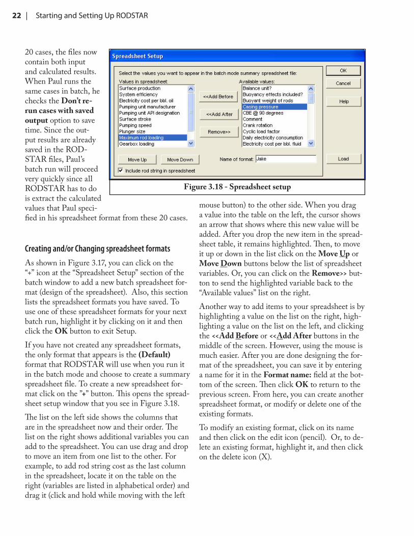
20 cases, the files now contain both input and calculated results. When Paul runs the same cases in batch, he checks the Don’t re-run cases with saved output option to save time. Since the out-put results are already saved in the ROD-STAR files, Paul’s batch run will proceed very quickly since all RODSTAR has to do is extract the calculated values that Paul speci-fied in his spreadsheet format from these 20 cases.
Creating and/or Changing spreadsheet formatsAs shown in Figure 3.17, you can click on the “+” icon at the “Spreadsheet Setup” section of the batch window to add a new batch spreadsheet for-mat (design of the spreadsheet). Also, this section lists the spreadsheet formats you have saved. To use one of these spreadsheet formats for your next batch run, highlight it by clicking on it and then click the OK button to exit Setup. If you have not created any spreadsheet formats, the only format that appears is the (Default) format that RODSTAR will use when you run it in the batch mode and choose to create a summary spreadsheet file. To create a new spreadsheet for-mat click on the ”+” button. This opens the spread-sheet setup window that you see in Figure 3.18.The list on the left side shows the columns that are in the spreadsheet now and their order. The list on the right shows additional variables you can add to the spreadsheet. You can use drag and drop to move an item from one list to the other. For example, to add rod string cost as the last column in the spreadsheet, locate it on the table on the right (variables are listed in alphabetical order) and drag it (click and hold while moving with the left
mouse button) to the other side. When you drag a value into the table on the left, the cursor shows an arrow that shows where this new value will be added. After you drop the new item in the spread-sheet table, it remains highlighted. Then, to move it up or down in the list click on the Move Up or Move Down buttons below the list of spreadsheet variables. Or, you can click on the Remove>> but-ton to send the highlighted variable back to the “Available values” list on the right.Another way to add items to your spreadsheet is by highlighting a value on the list on the right, high-lighting a value on the list on the left, and clicking the <<Add Before or <<Add After buttons in the middle of the screen. However, using the mouse is much easier. After you are done designing the for-mat of the spreadsheet, you can save it by entering a name for it in the Format name: field at the bot-tom of the screen. Then click OK to return to the previous screen. From here, you can create another spreadsheet format, or modify or delete one of the existing formats. To modify an existing format, click on its name and then click on the edit icon (pencil). Or, to de-lete an existing format, highlight it, and then click on the delete icon (X).
Figure 3.18 - Spreadsheet setup
RODSTAR | 23
4 Running RODSTAR
To start RODSTAR, double click on its icon. After a few seconds you will see RODSTAR’s introductory window and then the RODSTAR main window. When RODSTAR first loads, only the new file, open file, setup, and help buttons are active on the toolbar. If you have not set up ROD-STAR then do so before entering a new case (see Chapter 1 for information on setting up ROD-STAR).
4.1 RODSTAR’s User InterfaceRODSTAR has a user-friendly interface that simplifies and speeds up data entry. The program uses standard Windows features along with other unique features we designed to make entering and changing data as easy as possible. Figure 4.1 shows how to access the most recently saved files and select the file you want to load into RODSTAR. If you are not familiar with Microsoft Windows, please take some time to study your Windows manual. Teaching you how to use Windows is beyond the scope of this manual (although many Windows procedures are explained). By taking the time to understand and learn how to use Win-dows, you will be able to effectively use not only RODSTAR, but any other Windows program. RODSTAR’s interface has most of the elements that are common to all Windows programs. For
example, all Windows programs have a menu bar with drop-down menus and a control menu box at the top left corner. You can access all menu items using either the mouse or the keyboard. Using the mouse is by far the easiest way. When selecting an item from a menu, visual clues tell you what will happen next.
♦ An item followed by no markings starts an action. (For example, click on File and then click on New.
♦ An item followed by an ellipsis (...) needs more information before taking action; normally, the additional information is entered into a dia-log box. (For example, click on File and click on Open…)
An easy way to load files you recently saved:RODSTAR has a most-recently-used file list on the File menu, as shown in Figure 4.1. Selecting
Figure 4.1 - The most recently saved file list
24 | Running RODSTAR
the Recent Files sub-menu will show you up to nine of the most recently accessed files. A file is placed at the top of the list whenever it is loaded, or saved with a new name. This list can also be ac-cessed by clicking on the drop-down button on the toolbar to the right of the open file icon.
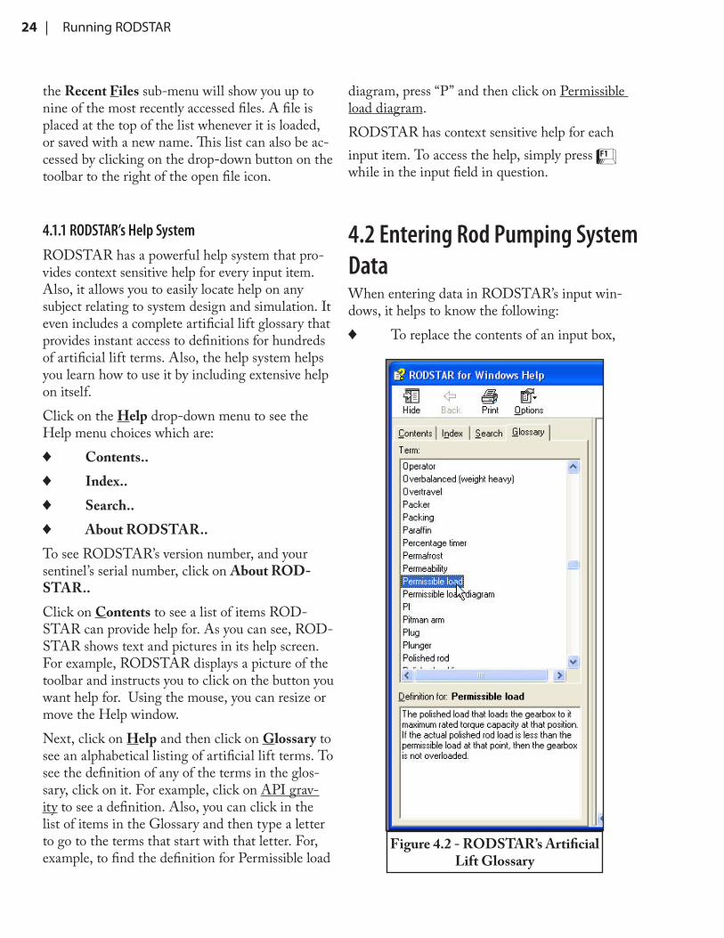
4.1.1 RODSTAR’s Help SystemRODSTAR has a powerful help system that pro-vides context sensitive help for every input item. Also, it allows you to easily locate help on any subject relating to system design and simulation. It even includes a complete artificial lift glossary that provides instant access to definitions for hundreds of artificial lift terms. Also, the help system helps you learn how to use it by including extensive help on itself.Click on the Help drop-down menu to see the Help menu choices which are:
♦ Contents.. ♦ Index.. ♦ Search.. ♦ About RODSTAR..
To see RODSTAR’s version number, and your sentinel’s serial number, click on About ROD-STAR..Click on Contents to see a list of items ROD-STAR can provide help for. As you can see, ROD-STAR shows text and pictures in its help screen. For example, RODSTAR displays a picture of the toolbar and instructs you to click on the button you want help for. Using the mouse, you can resize or move the Help window.Next, click on Help and then click on Glossary to see an alphabetical listing of artificial lift terms. To see the definition of any of the terms in the glos-sary, click on it. For example, click on API grav-ity to see a definition. Also, you can click in the list of items in the Glossary and then type a letter to go to the terms that start with that letter. For, example, to find the definition for Permissible load
diagram, press “P” and then click on Permissible load diagram.RODSTAR has context sensitive help for each input item. To access the help, simply press ! while in the input field in question.
4.2 Entering Rod Pumping System DataWhen entering data in RODSTAR’s input win-dows, it helps to know the following:
♦ To replace the contents of an input box,
Figure 4.2 - RODSTAR’s Artificial Lift Glossary
RODSTAR | 25
double click it before typing in it. ♦ If an input window contains a name that is
made up of more than one word, double click any word to select it. Then, to replace it, simply type a new word.To enter rod system data in RODSTAR for the first time, click on the first icon on the toolbar or open the File menu and select New. This opens the Well Information input window, shown in Figure 4.3. You can move this window with the mouse by dragging it to the desired location. Also, you can use the mouse to resize this input window.RODSTAR’s input windows use the following unique color scheme:
♦ Required data input fields appear with a yellow background. You must enter data in these fields before closing the window, continuing to the next window, or running the calculations.
♦ The active input field or list box appears in cyan.This color scheme helps you to easily see what data you need and where you are in the input window. There are two ways of moving around in an input window. You can click the input field you want, or you can enter data in order by pressing T to move forward from field to field. Also, you can press S+ T to move backwards. After enter-
ing data in fields with yellow background color, their color changes to white when you move to the next field.You can get context sensitive help for any input field by pressing !. Please use the context sensi-tive help as often as possible because it contains important information that will allow you to make better use of RODSTAR. Also, the context sensi-tive help makes you aware of program assumptions or limitations.
4.2.1 Entering Well Information DataIf you entered a company name in Setup, it appears in the Company name field. This saves you from having to enter the same company name every time you enter data. The date defaults to the date in your computer’s memory. If the date in your computer is not correct, you can type over it. The well name is required because RODSTAR uses it to create the default file name when you save data to disk.The pump condition panel allows you to select pump condition and pump efficiency or pump fillage. To select one of these input fields click on the input field or its label. Press ! while in one of these fields for some useful information.The option to have the pump condition and fillage
Figure 4.3 - The Well Information input window
26 | Running RODSTAR
calculated works along with the Production Infor-mation window. When you select this option you must enter a pumping speed and IPR data in the second input window. Based on the SPM you en-ter, RODSTAR calculates the pump displacement versus maximum available production from the IPR data as well as the final pump intake pressure. RODSTAR uses an iteration scheme to converge to the correct pump condition and pump fillage that will result from the SPM you enter, along with the calculated pump intake pressure.The Production Information window also gives you the option of having RODSTAR calculate the required pumping speed based on a target produc-tion you enter. However, the option of calculat-ing the SPM from your target production is only available if you select a full pump. For fluid pound or gas interference, you must enter a pump-ing speed in the Production Information window.
Other input data in the Well Information window:CommentYou can enter a comment about the case. You can type up to 100 characters in the comment field. The comment string you enter is included on the screen and printed outputs.
Pump Load Adjustment (RODSTAR-V Only)The pump load adjustment allows you to increase the fluid load picked up by the plunger. Usually this is unnecessary. However, this input allows you to account for extra downhole loads due to exces-sive downhole friction (for example due to wellbore deviation), or due to the “plunger effect” of large sinker bars. It is recommended that you use zero for this number unless you have more than 1000 feet of large sinker bars such as 15/8’’ or 1¾’’ bars in 2’’ tubing. The value of this number in pounds is typically 5% to 10% of the pump depth in feet. For example, for a pump depth of 6000 feet, enter a value of 300 to 600 pounds (but only if you use more than 1000’ of large sinker bars). RODSTAR
will not allow you to enter a value that is larger than 15% of pump depth. Also, you can use this input to add pump load for more conservative predictions.
Please note that RODSTAR assumes that the tubing-casing annulus is full of oil. It calcu-lates the specific gravity of the oil from the API gravity you enter. If you do not agree with this assumption then change the oil API gravity to correspond to the specific gravity you want RODSTAR to simulate. For example, if you want to simulate water in the casing-tubing annulus instead of oil, then enter an API gravity of 10 (which corresponds to a fluid specific gravity of 1.0).
Percent water cutThe percent water cut input along with oil API gravity allows RODSTAR to calculate a default specific gravity for the produced fluid. Also, it uses this data to calculate $/bbl (or $/m3) electricity costs.
Oil API gravityRODSTAR uses the oil API gravity to calculate fluid load on the plunger and the default specific gravity of the produced fluid. Also, as discussed above, RODSTAR uses this number to calculate the specific gravity of the fluid in the casing-tubing annulus which it assumes to be 100% oil.
Fluid specific gravityRODSTAR uses the oil API gravity and per-cent water cut you entered to calculate the default specific gravity of the produced fluid. The program will display this value when it prompts you to enter the fluid specific gravity. RODSTAR calculates the default specific gravity without considering free gas. This is okay for designing new wells since we prefer to be more conservative. However, if you want to simulate an existing system that produces gas, you must enter a lower number than the one
RODSTAR | 27
calculated by RODSTAR. With some experience and with “history-matching” between predicted and actual dynamometer cards you can come up with effective specific gravities that will accurately model your rod pumping systems. If you use a specific gravity that only considers liquids, it will result in higher predicted loads, power consump-tion, etc.If you are designing a new system and you are not sure what the specific gravity is, use the higher value you expect to have to make sure that your system will not be overloaded when in operation. However, when matching measured dynamometer cards, use a specific gravity that is as close as pos-sible to the actual value.After you finish entering data for the Well Infor-mation window click on the next screen button (right arrow) on the toolbar to open the Production Information input window. To move back to the previous window, simply press the left arrow icon on the toolbar.
Remember that pressing @ converts to the op-posite system of units. For example, if you selected English units but want to enter the pump depth in feet, press @ before entering the value. If the value for any field with units has already been entered, pressing @ will show it in the opposite units.
4.2.2 Entering Production InformationThe Production Information input window allows you to enter a fluid level or pump intake pressure as shown in Figure 4.4. Also, you can select to enter a pumping speed, enter a target produc-tion (the program will cal-culate the pumping speed to get the target production),
or you can select to calculate the target production from inflow performance data.If you choose to enter IPR data, the Production Information window expands to reveal the data you must enter. This includes the correlation you want to use for the inflow performance relationship (IPR), the depth from surface to the middle of the perforations, the static bottom hole pressure, and bubble point pressure. Also, you can enter from one to 10 test points. If you select to use the Vogel method for the oil IPR calculations then you only need one point. If you use Vogel and enter more than one point, then only the first point is used. You can enter more than one test point if you use the Fetkovich method. The pressure that cor-responds to each production test point can either be pump intake pressure or flowing bottomhole pressure (in the middle of the perfs). To add a new pair of Pi and Fluid production data, click on the add button (top right) icon. To delete a set of data points, click on the remove icon (bottom right).
You can get help for any input item by pressing ! when in the input field or by clicking on the ques-tion mark icon on the toolbar.If you do not know what the bubble point pres-
Figure 4.4 - The Production Information input window
28 | Running RODSTAR
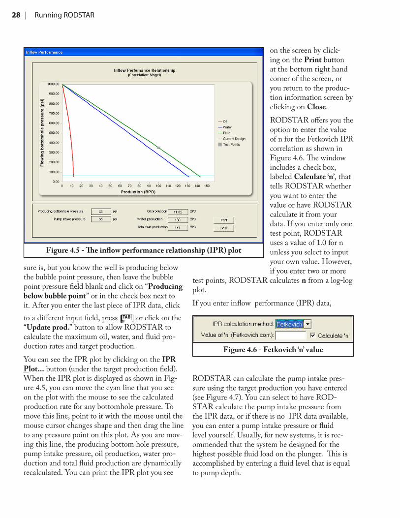
sure is, but you know the well is producing below the bubble point pressure, then leave the bubble point pressure field blank and click on “Producing below bubble point” or in the check box next to it. After you enter the last piece of IPR data, click to a different input field, press T or click on the “Update prod.” button to allow RODSTAR to calculate the maximum oil, water, and fluid pro-duction rates and target production. You can see the IPR plot by clicking on the IPR Plot... button (under the target production field). When the IPR plot is displayed as shown in Fig-ure 4.5, you can move the cyan line that you see on the plot with the mouse to see the calculated production rate for any bottomhole pressure. To move this line, point to it with the mouse until the mouse cursor changes shape and then drag the line to any pressure point on this plot. As you are mov-ing this line, the producing bottom hole pressure, pump intake pressure, oil production, water pro-duction and total fluid production are dynamically recalculated. You can print the IPR plot you see
on the screen by click-ing on the Print button at the bottom right hand corner of the screen, or you return to the produc-tion information screen by clicking on Close.RODSTAR offers you the option to enter the value of n for the Fetkovich IPR correlation as shown in Figure 4.6. The window includes a check box, labeled Calculate ‘n’, that tells RODSTAR whether you want to enter the value or have RODSTAR calculate it from your data. If you enter only one test point, RODSTAR uses a value of 1.0 for n unless you select to input your own value. However, if you enter two or more
test points, RODSTAR calculates n from a log-log plot.If you enter inflow performance (IPR) data,
RODSTAR can calculate the pump intake pres-sure using the target production you have entered (see Figure 4.7). You can select to have ROD-STAR calculate the pump intake pressure from the IPR data, or if there is no IPR data available, you can enter a pump intake pressure or fluid level yourself. Usually, for new systems, it is rec-ommended that the system be designed for the highest possible fluid load on the plunger. This is accomplished by entering a fluid level that is equal to pump depth.
Figure 4.5 - The inflow performance relationship (IPR) plot
Figure 4.6 - Fetkovich ‘n’ value
RODSTAR | 29
4.2.3 Entering Pump and Tubing Information DataOn the third input screen, you can select the tubing size, tubing anchor depth (if anchored), pump type, plunger size, and the upstroke and downstroke rod-tubing friction coefficients. Also, for shallow, high rate wells, you can include fluid inertia effects. If you select to include fluid inertia1 effects then you must also enter the fluid compressibility index. For more information on this option read the discussion that follows later in this section, or use the context sensitive help system.You can select the pump plunger size from a list of standard sizes, or you can enter a non-standard size by selecting “Other” from the list of plunger sizes. If you are simulating a full pump and you entered a target production, you can select to have RODSTAR recommend the pump plunger size for you. This option is only available when you enter a target production and select full pump for pump condition. Please note that the pump type you select affects the plunger size that the program will recommend. It may be interesting to make one run with an insert pump type and one with a tubing pump to see what RODSTAR recommends.
Other input data in the Pump and Tubing Information window:Rod-tubing friction coefficientsFor rod-tubing friction , RODSTAR-V allows you to enter upstroke and downstroke friction coefficients yourself, or you can have the program calculate them for you. If you do not know what to enter, then choose to have RODSTAR-V cal-1 Fluid inertia effects are dynamic effects that increase fluid load on the plunger in wells less than 4000 feet with pump plungers larger than 2.0 inches
culate the rod-tubing friction for you. The friction factors calculated by RODSTAR-V are estimates for average friction for a vertical wellbore. If you are simulating a system with excessive downhole friction, you must enter your own rod-tubing fric-tion coefficients for more accurate results. There are several downhole conditions that increase rod-tubing friction such as: wellbore deviation, a well with heavy oil production, paraffin or scale problems, etc.
The most accurate way to figure out the rod tubing friction in RODSTAR-V is to import a measured dynamometer card from a RODDIAG or XDIAG file. Then, “history-match” this actual card by manu-ally adjusting the friction. You do this by varying the upstroke and downstroke rod-tubing friction coefficients until the surface dynamometer card predicted by the program matches the measured dynamometer card. This technique allows you to find the rod-tubing friction that gives the best results when simulating this system. From then on you can use these friction factors every time you simulate this pumping system.
Please note that this “history-matching” technique works only if the dynamometer card that you mea-sure corresponds to a pump condition that ROD-STAR can simulate (full pump, fluid pound, or gas interference). For example, if the pump is worn out or is hitting up or down, etc., then this technique will not work as well. This is because you will be unable to get a good match between predicted and measured dynamometer cards. If you do not have a measured dynamometer card, use the following guidelines for entering rod-tub-ing friction coefficients in RODSTAR-V:1. First select to have RODSTAR-V calculate
Figure 4.7 - Options for calculating pump intake pressure
30 | Running RODSTAR
the rod-tubing friction coefficients for you. You can use these calculated values as guidelines to decide what values to enter yourself to better simulate your rod pumping system.
2. For heavy oil or for wells with paraffin or scale buildup, use 2-3 times the value calculated by RODSTAR-V. You can use the same guideline for deviated wells when the deviation is close to the bottom of the wellbore.
3. For deviated wells with the deviation close to the surface you may need to enter a larger number such as 4-6 times as high as the values calculated by the program. Also, it may be appropriate to use different values for upstroke and downstroke frictions to better match your downhole conditions.
The above comments refer to RODSTAR-V. RODSTAR-D can calculate the effect of deviation (such as side load) from the deviation survey.
RODSTAR-D Friction CoefficientsIn RODSTAR-D, the upstroke and downstroke rod-fluid damping coefficients on the pump and tubing information window are only for fluid damping on rods. RODSTAR-D also allows you to enter rod-tubing friction (drag) coefficients for each rod string section in the rod string input win-dow. The default bare rod rod-tubing drag friction coefficient is 0.2. The range for this value is from 0.1 (for oil lubrication between smooth rods and tubing) to 0.3 (for high water cut wells and rough rod and tubing surfaces). Again, the best way to determine what to use is by plotting a measured dynamometer card on the same plot as the pre-dicted dynamometer card and changing the values of the rod-tubing friction coefficients for each sec-tion of the rod string. You can do this by loading a RODDIAG or XDIAG file into RODSTAR.To simulate the effect of rod guides, you need to adjust the friction coefficients for each section of the rod string. You can use the ratio of guide friction to bare rod friction to adjust the default friction coefficient. For example, the friction ratio
default value for molded rod guides is 1.5. This means that if you use molded rod guides, you need to increase the rod-tubing friction coefficient by 50% to accurately simulate the additional rod-tubing drag. So, if you use molded rod guides, you need to enter a friction coefficient of 0.3 (0.2*1.5=0.3) for the section of the rod string with the molded rod guides.Rod guide manufacturers need to provide you with friction ratio values for the different rod guides they make.
Buoyancy effectsThe option to include buoyancy effects should be left unchecked in most cases. This is because buoyancy does not cause buckling of the rod string. However, for fiberglass-steel rod strings, after the design is finalized, It is recommended that an ad-ditional run be made including buoyancy effects to ensure that the fiberglass portion of the rod string is not in compression. If it is in compression, then more sinker bars must be used, the pumping speed need to be reduced, or both.When buoyancy is not included, the bottom of each rod section except the last section should have a positive stress. Otherwise the rods may be going into buckling. It is normal for the very bottom of the rod string to be in compression if you enter a pump friction that is not zero (a minimum pump friction of 200 lbs is recommended).For more information on the theory behind these recommendations, please read SPE paper num-ber 25416 “Interpretation of Calculated Forces on Sucker Rods” by J. F. Lea and P. D. Pattillo. Pre-sented at the Production Operations Symposium in Oklahoma City, March 1993.
Fluid inertia effectsIf the well depth is less than 4250 feet and the pump plunger size is larger than 2.00 inches, RODSTAR allows you to consider fluid inertia effects. These dynamic effects become important
RODSTAR | 31
in wells with plungers larger than 2.0” and pump depths of 4000 feet or less. However, there is no exact “magic” depth for which fluid inertia be-comes important. Therefore, RODSTAR allows you to include these effects for wells up to 4250 feet deep and with a plunger size equal to or larger than 2.0”. Another important factor is fluid com-pressibility. The more compressible the fluid is, the less prominent the fluid inertia effects are.If you include fluid inertia effects, RODSTAR will prompt you for the fluid compressibility index. The default is 3 but you can vary this number between 1 and 7 (x10-6 psi-1). The compressibility index tells RODSTAR how compressible the fluid in the tubing is. The value of the compressibility index affects the shape of the predicted dynamometer cards (surface and downhole). If you are not sure what number to use, experiment with different values until you can match measured dynamometer cards for the well you are simulating. When you include fluid inertia effects, pump efficiency becomes a variable that affects the dynamic fluid load on the plunger. Therefore, using 90% pump efficiency gives higher peak polished rod load than using 80%.The option to include fluid inertia effects is only available if you are modeling a full pump. Please do not confuse fluid inertia effects with the mo-ments of inertia of the pumping unit that have to do with gearbox torque due to prime mover speed variation. Fluid inertia effects refer to additional dynamic forces on the plunger caused by the pickup and rapid acceleration of the fluid load.RODSTAR simulates fluid inertia effects with a second wave equation that models the pressure waves in the fluid in the tubing. This increases simulation accuracy by accounting for pressure pulses traveling up and down in the tubing fluid. These pressure waves have a direct affect on the pump plunger. Since the program has to do many additional calculations when you include fluid inertia effects, RODSTAR may take 60%-80% longer to run.
4.2.4 Entering Rod String DataThe fourth input window deals with the rod string design. As Figure 4.8 shows, you can select one of the three available rod string entry options:RODSTAR Steel design, RODSTAR Fiberglass-Steel design, or Manual rod string entry. The symbols for these options are explained in Figure 4.8.
RODSTAR Steel DesignIf you select this option, RODSTAR displays a window such as the one shown in Figure 4.9. Here, you can select the maximum and minimum rod diameters to consider, whether to include sinker bars, the service factor, and additional rod costs.If you want to include sinker bars then you must enter the diameter and length of the bar (or sinker rod). RODSTAR does not calculate the length of the sinker bar section because there is no industry consensus on how to design sinker bars. However, RODSTAR will design the rod string above the sinker bar section you specify. RODSTAR attempts to design an optimum rod string based on the rod grade and the maximum and minimum rod diameters you enter. First, RODSTAR figures out how many rod tapers are needed. Then, it automatically adjusts the length of each section until the stress loading is the same
Figure 4.8 - Rod string entry options
32 | Running RODSTAR
at the top of each rod section. This equalizes and minimizes stress loading on the rod string. This “stress balancing” approach gives the lowest cost rod string with equally distributed stress loading, for the rod grade you select.This approach works the same regardless of steel rod grade or type. For example, you can have RODSTAR design a Corod rod string for semi elliptical “Ultra” Corods using a maximum diam-eter of 17/16”, a minimum diameter of 13/16”, and a 375’ section of 1 5/8’’ sinker bars on the bot-tom. RODSTAR uses only the rod sizes it needs. For example, if the loads are not high enough to require the use of the 17/16” rod diameter then RODSTAR will go to the next size (16/16”). If this is still too big, it will use the 15/16”.The maximum rod loading used by RODSTAR to decide when the next larger diameter rods are needed is 95% by default. However, you can change this number if you like by going to the Setup “Defaults” window.
Fiberglass/steel RODSTAR designIf you select the option to have RODSTAR-V de-
sign a fiberglass-and-steel rod string, you will see the data input screen in Figure 4.10. For example, let us say you want to use a design with fiberglass rods on top followed by a tapered steel section with 1” and 7/8” rods, and then 375 feet of 1” sinker bars. RODSTAR is able to design this rod string for you. Also, it balances the steel design under the fiberglass section (for two or more rod sections) so that there is equal stress loading at the top of each section as shown in Figure 4.11. This Figure shows a fiberglass-steel rod string designed with RODSTAR-V. RODSTAR-V can design tapered steel rod strings under the fiber-glass section for any type of steel rod, including non-API high strength rods, and Corods. If you want to fine-tune a RODSTAR design, select to enter your own rod string design by clicking on the manual rod string entry icon. RODSTAR will show you the current rod string design in memory as if you entered it yourself. Then, you can make any changes you want to the rod string without having to reenter everything.Also, you can have RODSTAR design the rod string while calculating the pumping speed and plunger size, to get the target production. How-ever, because of the complexity of the calculations,
Figure 4.9 - Steel rod string design options
RODSTAR | 33
simultaneous use of all or most of RODSTAR’s “smart” options will result in longer run times. This is especially true if you also select to include the effect of prime mover speed variation. Also, depending on the case, RODSTAR’s run time may be longer if you enter a target production that is too large for the pumping system.If you select only sinker bars on the bottom (with-out regular steel rods between the fiberglass and sinker bar) then RODSTAR will calculate the length of the sinker bar section for you. If you select both sinker bars and a tapered steel design
between the sinker bars and the fiberglass rods, then you must enter the length of the sinker bar (or sinker rod) section. RODSTAR will determine the length and diameters of the tapered steel portion based on the maximum and minimum diameter limits you enter.RODSTAR may reject a steel rod diameter if it is not needed. For example, if you asked RODSTAR to design a rod string with fiberglass on top, a tapered steel section under the fiberglass, and a 500 foot 1.5 inch sinker bar section on the bottom. RODSTAR will determine the fiberglass diameter
Figure 4.10 - Fiberglass rod string design window
Figure 4.11 - RODSTAR Designed Fiberglass-Steel Rod String
34 | Running RODSTAR
and length you need, and the steel rod section and tapers you need. If RODSTAR cannot balance the steel rod string design because the 3/4’’ section is not needed, it will not use any 3/4” rods. Another interesting capability of RODSTAR is that if you use continuous rods (Corod or Prorod) instead of regular rods under the fiberglass, it may skip a rod diameter, if it has to, in order to bal-ance the rod string stress loading. This is not a bug. Sometimes the program has to do this to success-fully balance the steel portion of the rod string.
Entering Your Own (Manual) Rod StringThis option is primarily used for entering rod string data for an existing system you want to simulate, or to modify a design that RODSTAR itself came up with (when you select to have the program design the rod string for you). This is not a good option to use when you first design a new system because it requires the most work and experience.When you select this option, you can enter data for either steel or fiberglass rods as Figure 4.12 shows. You can enter the number of rod sections, the ser-vice factor you want to use, and rod string data for up to ten rod sections. For each section, you can
select the rod type or grade, diameter, and length. For Fiberflex fiberglass rods you can also specify the sucker rod length. In RODSTAR-D, for each rod section, you may also enter the rod-tubing fric-tion coefficient, the type of rod guide, and number of rod guides per rod. The rod-tubing friction is used to calculate the friction between the rods and the tubing. This is different from the fluid friction coefficient which is used to calculate the friction between the rods and the fluid. In order to enter the number of rod guides for each section, you must activate this feature in Setup. There is more information about this in section 3.3.3.If you select one of the fiberglass manufacturers listed on the drop down list next to the rod grade input field, the program knows the weight per foot and modulus of elasticity and will not prompt you for them. The program warns you about rods that do not fit in the tubing. Also, it warns you if the rod string length is shorter or longer than the pump depth. The total length of the rod string can be up to 50 feet shorter than the pump depth. However, it cannot be longer than the pump depth. For example, if the pump depth is 5000 feet, you can enter a rod string that is between 4950 and 5000 feet. When entering rod string data for the first time, RODSTAR shows a default length for the last rod section equal to the differ-
Figure 4.12 - Selecting rod grades in RODSTAR
RODSTAR | 35
ence between the pump depth and the rod string length you entered so far.Selecting the option to enter your own rod string gives you maxi-mum flexibility. How-ever, it requires the most expertise to come up with a good rod string design. You can use this option to select differ-ent rod grade or manu-facturer for each rod section. In general, this option allows you to en-ter any rod string design, no matter how unusual. The minimum length you can enter for any rod section is 25’ (length of a single sucker rod).When entering the rod string data manually, RODSTAR allows you to add and remove rod sec-tions from anywhere in the rod string, instead of only at the bottom. The window has icons on the left side for inserting a rod section, for removing a rod section, or for moving a section up or down. For example, if you want to remove a rod section, first click on it and then click on the Delete Rod rod section icon. To add a rod section, click on an existing rod sec-tion and then click on the Insert/Add Rod Sec-tion icon. The new section will be added below the selected section.RODSTAR asks for confirmation whenever you remove sections from the rod string, whether by using the Remove rod section button or by reduc-ing the number of rod sections.
The meaning of the term “Sinker Bar” in RODSTARIn RODSTAR, the term “sinker bar” means a steel rod that is made specifically to be used at the bottom of the rod string for weight such as 1 3/8”,
1½”, 1 5/8”, etc. The term “sinker rod” means a regular rod such as a 1” or 7/8” rod that is placed on the bottom of the rod string for weight. For a 1” or 7/8” rod to be considered a “sinker rod” it must be larger than the diameter of the rod above it.When entering the rod string manually, make sure you select “Sinker bars” in the list of rod grades for sinker bars as shown in Figure 4.11. Do not select “Steel” rod type and then “Other” for the rod size.
Figure 4.13 - Wellbore deviation entry window
Figure 4.14 - Deviation entry icons
36 | Running RODSTAR
Manual Entry of Deviation SurveyTo enter the deviation survey manually, you need to know how many deviation points you have and the measured depth, inclination and azimuth of each devia-tion survey point.Start by entering the number of survey points as shown in Figure 4.15. As soon
Figure 4.16 - Entering deviation data manually
Figure 4.17 - Import Wizard Options
Figure 4.15 - Enter the number of entries
4.2.5 Entering Wellbore Deviation Data (RODSTAR-D)
RODSTAR-D has an additional input window for entering wellbore deviation shown in Figure 4.13. Figure 4.14 explains the meaning of the icons shown on the left side of this input window. You can activate these icons by clicking on them with the mouse.
RODSTAR | 37
as you enter this number, the program will created the correct number of rows for you to enter the data as shown in Figure 4.16. The easiest way to enter the data is by using the tab key to move from field to field.The “Add Entry” and “Remove Entry” buttons can be used as needed. At any time during the data entry, you can click on the “Plot Survey” tab to see a 3-D plot of the well-bore deviation entered so far. When inputting the Azimuth, ROD-STAR recognizes both degrees (i.e. 340) and degrees/minutes formats (i.e. N20W or N20 0W). As you continue to enter the deviation data, the program calculates the numbers in the other columns of the de-
viation input window. These numbers are Dogleg severity, True Vertical Depth (TVD), North-South distance (N-S), and East-West (E-W) distance in feet or meters.Double-check your data to make sure you are entering the num-bers correctly (espe-cially if you see dogleg severity numbers in red).If RODSTAR is be-ing used to analyze an existing well, the Deviation Survey Di-rection Toolbar should
be disabled. To disable this toolbar, click the Setup icon, click the Defaults option, and uncheck the box labeled “Show Deviation Direction Toolbar”. The Deviation Survey Direction Toolbar is used to design a deviated well. While the toolbar is active,
Figure 4.18 - Step 1 of the Deviation Import Wizard
Figure 4.19 - Step 2 of the Deviation Import Wizard
38 | Running RODSTAR
Figure 4.20 - Step 3 of the Deviation Import Wizard
Figure 4.21 - The last screen of the Deviation Import Wizard
RODSTAR | 39
Figure 4.22 - The deviation survey after it was imported
Figure 4.23 - The 3-D Plot of the deviation Survey
40 | Running RODSTAR
the Azimuth is input in degrees and the toolbar is utilized to designate a direction. Select a direction first, then input the degree value. The field will be automatically updated with the direction once the field is left.NOTE: The NE direction is the default and will not display any directional indicators (i.e. N20E or N20 0E will be displayed as 20).
Using the Deviation Survey import Wizard
You can use the deviation import wizard option to import an Excel spreadsheet or CSV file with de-viation data, or to import a deviation survey from a Theta software file which contains deviation data. The two Theta file types that contain direc-tion survey data are RODSTAR-D files (extension “.rsdx”) and XDIAG-D files (extension “.xddx”).To Import a Deviation Survey, click the “Import Wizard” button. Using the Import Wizard Dia-log window, select the source of your Deviation Survey. In this example we are using a Microsoft Excel spreadsheet.Step 1 prompts you to select the file to be imported as shown in Figure 4.18.Step 2 allows you to select the Workbook and Spreadsheet to use in cases where there are more than one in the Excel file as shown in Figure 4.19.Step 3 automatically locates the columns in the spreadsheet where the values are stored for the Measured Depth, Inclination, and Azimuth as shown in Figure 4.20.The next step loads the data and then finishes as shown in Figure 4.21.Click “Done” and view the imported deviation survey data as shown in Figure 4.22.Please keep in mind that for program to be able to load the deviation data from an Excel spreadsheet, it must see three columns with the deviation data. These columns need to be labeled as follows:“Measured Depth (ft)” or “MD (ft)”, or “MD (m)”“Inclination”
“Azimuth”Clicking the “Plot Survey” tab on the right side of the window will display the Deviation Plot as shown in Figure 4.23. From this screen, you can rotate the plot to better understand and visualize the wellbore deviation, you can zoom in, etc.
4.2.6 Entering Pumping Unit DataThe pumping unit input screen allows you to select a pumping unit from the database that comes with RODSTAR, or from your measured pumping unit database (if you entered your own pumping unit dimensions in Setup). Another option is to enter a pumping unit ID.The pumping unit ID is a unique string of letters and numbers. RODSTAR displays the pumping unit ID along with other unit information after you select a unit. If you make a note of this unit ID (in the well file for example), you can use it to specify the pumping unit instead of having to select it from the list. This is a unique ID for each pumping unit in the program’s database.Selecting a pumping unit manufacturerRODSTAR allows you to easily select a pumping unit manufacturer and unit size with drop-down list boxes. To display the menu with all pumping unit types available, click on the drop arrow next to the “Manufacturer” field (see Figure 4.24). This is a scrollable list of all units in the program’s database in alphabetical order. You can go to the
top of the list by pressing }. You can jump to
the bottom of the list by pressing ~. You can
also move up or down by pressing O (Page up)
or N (Page Down). A convenient way to move through the list is to press the first letter of the unit name you want to use. For example, to locate the National “E” Series pumping unit entry, you
can press n and the highlight bar will jump to the first name in the list that starts with N. Then simply click on the National “E” Series entry. At
RODSTAR | 41
the top of the list of pumping unit manufactur-ers is the item (Measured pumping units). This option allows you to select a unit for which you entered geometric data in Setup. When you select the (Measured pumping units) option, RODSTAR will display a list that only shows the measured pumping units, as Figure 4.25 shows. As Figures 4.24 and 4.25 show, there is a check box that allows you to use the custom pumping unit list instead of the main pumping unit list. If you check this option, before you select a unit, the Manufacturer list will show a shorter list that contains only the manufacturers you selected in Setup in your custom unit list as shown in Figure 4.26. When the “Use custom pumping unit list” option is checked, when you select a pumping unit, you will see a short list containing only the unit
sizes you selected for your customized list for this manufacturer.After you select a manufacturer you can use the same procedure to select the unit size you want from the pumping unit drop-down list box . You can move through this list the same way as with the pumping unit manufacturer selection menu. The pumping units on this menu are ordered from largest to smallest stroke length, gearbox size, and structure size. However, if the window shows the pumping unit name (for old units) the units are listed alphabetically.When you enter a unit, the Unit ID, the program automatically displays the unit that the ID cor-responds to. RODSTAR displays the information necessary for you to correctly identify your unit. For example, for American conventional units you will see that certain unit sizes appear more than
Figure 4.24 - Pumping unit manufacturer list
42 | Running RODSTAR
once on the selection list. However, they have dif-ferent cranks.
How to add units to the custom pumping unit listYou can use the “Use custom pumping unit list” check box to add units from the main list to your custom list. For example, if you run across a pump-ing unit that is not in your custom list yet, clear the “Use custom pumping unit list” check box so that you can use the general pumping unit list. After you select the pumping unit then click on the “Use custom pumping unit list” check box. RODSTAR asks if you want to add this pumping unit to the custom pumping unit database. Select Yes to add this unit to your custom list. The pro-gram will add this unit to the custom list and also switches to the custom list.This option only allows you to add units to your custom list without having to do it from Setup. To remove units from your custom list or to add more than one unit, go to the setup window and cus-
tomize the list of units as described earlier in this manual.
Selecting to enter a pumping unit IDThe unit ID option is the fastest way to enter pumping unit information if you already know the pumping unit ID for your unit. You can see the pumping unit ID on the pumping unit entry window after you select a unit. Once you locate your unit, you can make a note of its ID in the well file. Then, the next time you want to use this unit, you can select to enter its ID. For example, for a Lufkin Mark II M-456-305-144, the unit ID is ML32. To identify some units correctly, it is necessary to know the crank number since they may have the same API designation but different geometric dimensions depending on crank number (primarily units made by American International Manufac-turing Company).TIP: If your unit is not listed in RODSTAR
Figure 4.25 - Measured pumping unit list
RODSTAR | 43
and you do not have the unit dimensions, then use a unit that is closest to it. As long as you use the same unit geometry and a unit with the same stroke length and gearbox rating, the results should be close to actual as long as the pumping unit is the same unit type as the one you selected.If after you enter a pumping unit ID RODSTAR displays “The pumping ID you entered is not valid” this means that ID you entered is not recognized by RODSTAR. This can happen for two reasons:1) You entered the wrong ID such as R0 (which does not exist), or CL901 instead of CL91.2) You have erased the pumping unit file by acci-dent, or the pumping unit files are not in the same directory as the program.RODSTAR Recommended unit sizeIf you enter a target production instead of pump-ing speed, RODSTAR will display a recommended pumping unit size to help you select a pumping unit. This recommendation can be very helpful if you are designing a new pumping system and must decide what size unit you need. RODSTAR
recommends sizes that are closest to conventional units as Figure 4.27 shows. Therefore, if you plan to use uncommon unit geometries such as the Rotaflex, then this recommendation may not be as useful. RODSTAR makes this recommendation without running through the predictive calcula-tions. Therefore, it may not necessarily recommend the best pumping unit size for your application. However, in most cases it should be pretty close to the size you need.There are other important factors that you must consider when deciding what unit size you need. These include: available used pumping units, ex-pected changes in well conditions, desired pump-ing speed, etc. When you enter data for a case for the first time and you are at the pumping unit selection screen, RODSTAR will not only display the recommended unit size, but will automatically select the unit closest to the recommended size from the available list. If you do not want to use the unit recommended by RODSTAR then select another one. The recommended unit size is a push button, as shown in Figure 4.27. So, whenever you
Figure 4.26 - The custom pumping unit list
44 | Running RODSTAR
want to return to the pumping unit size recom-mended by RODSTAR, just click the button and RODSTAR will automatically select the unit size that is closest to the recommended size. In general, the size recommended by RODSTAR will be close to the minimum required conventional unit. RODSTAR recommends only the API unit size. You must decide what manufacturer and unit type to use. If you select a conventional unit and RODSTAR predicts that the gearbox will be overloaded, then try using the same size Mark II or enhanced geometry unit. In some cases you may be able to use a smaller unit by selecting a geometry that is better suited for your application. There are several factors that determine what unit is best. They include, cost, gearbox loading, system efficiency, rod compression, minimum polished rod load (indicates separation of the polished rod from the carrier bar if close to zero), etc.
Selecting crank hole number and crank rotationAfter you select a pumping unit you must select the crank hole number, and the direction of rota-tion with the well to the right (if you are using a unit that can rotate either way). For units with a required direction of rotation, like the Mark II , Torqmaster, Lufkin Reverse Mark, or American Producer II, the program will not allow you to change crank rotation. For units that can rotate either clockwise or counterclockwise, RODSTAR defaults to the direction of rotation that will usu-ally give the lowest torque. However, this default direction of rotation may not always be ideal for your system design. To find out for sure which rotation is best for your system you must make two runs: one with clockwise crank rotation and one counterclockwise. Then look at the effect of rotation on gearbox torque, system efficiency, rod loading, etc.
Figure 4.27 - RODSTAR recommends a unit size based on target production
RODSTAR | 45
Entering your own pumping unit dataIf the pumping unit you want to simulate is not in RODSTAR’s database, you can enter your own pumping unit dimensions. To enter the data in the program you have to first access the setup screen of RODSTAR (click on fourth button on toolbar). Then, double-click on “Pumping Unit Options” tab and select “Measured Pumping Unit List” as explained in section 3.3.5 in this manual. Then, select to add a new unit to enter data for a new pumping unit.The data you must enter consists of geometric dimensions as defined in the API 11E publication. You can get these dimensions from the pumping unit manufacturer or measure them yourself. Or, you may be able to find most of the dimensions you need from catalogs or blue prints. For old units without an API designation on their nameplate, you may be able to put together an equivalent API designation. Look at the gearbox nameplate for the gearbox rating in thousands of in-lbs. Measure the stroke length, and try to decipher additional infor-mation from the unit’s nameplate for the structure rating, stroke length, and structural unbalance. If the nameplate is legible then write down the unit’s serial number or order number. If the unit’s manufacturer is still in business, you may be able to get the data you need from the serial number or order number. For help in locating dimensional data for pumping units not in the manual call Theta Oilfield Services, Inc..RODSTAR allows you to enter data for Conven-tional, Mark II, Air Balanced, Enhanced Geom-etry, or Long Stroke units. When you enter your own pumping unit dimensions, RODSTAR cal-culates and displays the stroke length based on the dimensions you enter. For all pumping unit types you must first enter the name of the manufacturer, the unit name or model number, the gearbox rat-ing in thousands of inch pounds, the structure rating in hundreds of pounds, and the maximum stroke length in inches. From these numbers RODSTAR puts together the API pumping unit designation. The API pumping unit designation is a standard way of describing the size and capacity
of pumping units as the following example ex-plains:The first number is the gearbox rating in thousand inch-pounds. In this example the gearbox rating is 320,000 inch-lbs. The second number is the struc-ture rating in hundreds of pounds. In this case the structural rating is 256. This means that to avoid overloading the structure of the unit, polished rod load must not exceed 25,600 lbs. The last number shows the maximum stroke length of the unit in inches (100 inches in this case). Following is an explanation of the rest of the data needed for each unit type:
Conventional, Enhanced and Beam Balanced Geometry Pumping Unit DataFor these units you must enter pumping unit dimensions R, A, C, I, P, and K in inches, the structural unbalance in pounds, and the crank offset angle in degrees. For enhanced geometry units the crank offset angle must be negative. In the software, Beam Balanced units are balanced using structural unbalance. This is because they are balanced using beam weights as opposed to crank weights. The API spec. 11E defines the above dimensions as follows:
Dimension: Description:
Figure 4.28 - Conventional/Enhanced
46 | Running RODSTAR
R Radius of the crank (inches)A Distance from the centerline of the
saddle bearing to the centerline of the polished rod (inches)
C Distance from the centerline of the saddle bearing to the centerline of
the polished rod (inches)I Horizontal distance from the
centerline of the saddle bearing to the centerline of the crankshaft
(inches)P Effective length of the pitman
arm, in inches (from the center of the equalizer bearing to the center
of the crank-pin bearing) K Distance from the center of the
crankshaft to the center of the saddle bearing (inches). Some-times, instead of the K dimen-
sion, pumping unit manufacturers supply data for dimensions H and G instead (described below). From these dimensions and dimension I (defined above) you can calculate
K as follows: K= ( H-G ) + I2 2
H Height from the center of the saddle bearing to the bottom of
the base beams (inches)G Height from the center of the
crank shaft to the bottom of the base beams (inches)
Mark II Pumping Unit DataFor Mark II units you must also enter pumping unit dimensions R, A, C, I, P, and K in inches, the structural unbalance in pounds, and the crank offset angle in degrees. This angle is positive for Mark II units. The API spec. 11E defines the above dimensions as follows:
Dimension: Description:R Radius of the crank (inches)A Distance from the center of the
Sampson Post bearing to the cen-terline of the polished rod (inches)
C Distance from the centerline of the Sampson Post bearing to the cen-ter of the equalizer (or cross yoke)
bearing (inches)I Horizontal distance between the
centerline of the Sampson Post bearing and the centerline of the
crankshaft (inches)
Figure 4.30 - Mark II
Figure 4.29 - Beam Balanced
RODSTAR | 47
P Effective length of the pitman arm, in inches (from the center of the equalizer (or cross yoke) bear-ing to the center of the crank-pin
bearing)K Distance from the center of the
crankshaft to the center of the Sampson Post bearing (inches)
H Height from the center of the saddle bearing to the bottom of
the base beams (inches)G Height from the center of the
crank shaft to the bottom of the base beams (inches)
Air Balanced Pumping Unit DataFor these units you must also enter pumping unit dimensions R, A, C, I, P, and K in inches. In ad-dition, you need data for M, S and V0. The API spec. 11E defines the above dimensions as follows:
Dimension: Description:R Radius of the crank (inches)A Distance from the center of the
Sampson Post bearing to the cen-terline of the polished rod (inches)
C Distance from the centerline of the Sampson Post bearing to the center of the equalizer bearing
(inches)I Horizontal distance between the
centerline of the Sampson Post bearing and the centerline of the
crankshaft (inches)P Effective length of the pitman
arm, in inches (from the center of the equalizer bearing to the center
of the crank-pin bearing)K Distance from the center of the
crankshaft to the center of the Sampson Post bearing (inches).
M Geometry constant (in2). It is the distance from the Sampson Post bearing to air tank bearing (dis-tance X in Figure 2.3) multiplied by the area of the piston in the air cylinder divided by dimension A or: X*Ap/A, where Ap is the area of the air cylinder piston in square
inches.S Pressure in the air counterbal-
ance cylinder required to offset the weight of the walking beam,
horsehead, equalizer, pitman arms, etc. (psig).
V0 Minimum air volume between the plunger and cylinder at the bottom
of the stroke (in3).
Belted Low Profile Pumping Unit DataFor these units you must enter pumping unit dimensions R, D, I, and K in inches and the crank offset angle in degrees. The crank offset angle is
Figure 4.31 - Air Balanced
48 | Running RODSTAR
negative for these units. The structural unbalance for belted low profile units is negligible and there-fore zero because, when you disconnect the pitman arms from the belt, there is no counterbalance from the belt and bridal assembly. We define the above dimensions as follows:
Dimension: Description:R Radius of the crank (inches)D Diameter of the drum (inches)
which holds the beltI Horizontal distance from the
centerline of the saddle bearing to the centerline of the crankshaft
(inches)K Distance from the center of the
crankshaft to the center of the drum bearing (inches). Sometimes, instead of the K dimension, pump-ing unit manufacturers supply data for dimensions H and G instead (described below). From these di-
mensions and dimension I (defined above) you can calculate K
as follows: K= ( H-G ) + I2 2
H Height from the center of the drum bearing to the bottom of the
base beams (inches) G Height from the center of the
crank shaft to the bottom of the base beams (inches)
Long Stroke Pumping Unit DataFor these units you must enter the sprocket diam-eter (D), the centerline distance between the top and bottom sprockets (distance C), the pitman arm length (P) if one exists (usually this is zero), and the top drum diameter ratio (usually equal to 1). You can see a diagram of the dimensional data you need by pressing F1 in any input field, or you can take a look at Figure 4.33.You can also use this pumping unit model to simulate any non-beam pumping unit with a long, slow stroke. You can do this by entering data that will produce the same stroke length as the unit you want to model. The stroke length of a long stroke unit is given by:
Stroke = C + D For example, to simulate a hydraulic pumping unit with a stroke length of 200 inches, you can enter a sprocket diameter (D) of 20 inches and a centerline distance between sprockets equal to 180 inches. If you use this approach to design a system with a hydraulic unit then the torque calculations, energy consumption, and other results that depend on torque will be incorrect or meaningless. However, the predicted polished rod dynamometer card, polished rod horsepower, stress analysis, etc. will be valid. This technique can be used as long as the upstroke and downstroke polished rod velocities of the hydraulic or long stroke unit you want to simulate are approximately equal. Tip: To predict energy consumption more accu-
rately for hydraulic units using the long stroke pumping unit model, input a pitman arm length of zero and a drum diameter ratio of 2.Another thing to keep in mind is that even though the combination of C and D dimensions determines the stroke length of long stroke units, the ratio of C/D determines the acceleration and deceleration of the polished rod. For the long stroke geometry shown in Figure 4.33, when the connection point between the belt and the chain touches the sprocket, the polished rod speed changes (accelerates or decelerates). When the
connection point leaves the sprocket (C section in
Figure 4.32 - Belted Low Profile
RODSTAR | 49
Figure 4.33) the speed is constant. Therefore, dif-ferent combinations of C and D dimensions may be needed to correctly simulate the polished rod motion of a hydraulic pumping unit.
Definition of Structural UnbalanceStructural unbalance is a term used for pumping units with walking beams. It is defined in API 11E as the force you need at the polished rod to hold the walking beam horizontal with the pitman arms disconnected from the crank pins. This force is positive when acting down and negative when acting up. See Figure 4.34 for a visual explanation of structural unbalance. Structural unbalance for conventional units can be either positive or nega-tive. For Mark II units it is always negative. If you do not know the structural unbalance for the unit you want to simulate then enter zero. In most cases the structural unbalance will not affect the results significantly (especially for Conventional geometry units).
Definition of Crank Offset AngleThe crank offset angle (or crank phase angle) is the angle between a line through the crank holes and a line through the counterweight arm. Figure 4.35 shows how the crank offset angle is defined. RODSTAR expects a positive crank offset angle for Mark II units and a negative one for enhanced geometry units such as the Torqmaster, Lufkin Reverse Mark, or American Producer II. For conventional pumping units the crank offset angle is zero.
Entering Counterbalance InformationAfter you select a pumping unit or enter your own pumping unit data, the crank hole number, and direction of rotation, you must enter counterbal-
Figure 4.33 - Dimensions for long stroke units
Figure 4.34 - Definition of structural unbalance
Figure 4.35 - Definition of crank offset angle
50 | Running RODSTAR
ance information. Entering an existing maximum counterbalance moment allows you to simulate an existing sys-tem to find out if the unit is overloaded or out of balance. If you only want to find the maximum counterbalance moment required to balance the unit (which is usually the case for new designs) then click on the “Unknown” check box and RODSTAR will calculate it for you. For beam pumping units except for air balanced, you can enter a maximum counterbalance moment in thousand inch-lbs. RODSTAR also gives you the option to import the maximum counterbalance moment from a XBAL file or from the clipboard. If you ran XBAL before running RODSTAR, then the value of the existing maximum counter-balance moment will be in the clipboard. Then, as soon as you click on the Use XBAL information button, RODSTAR will allow you to use the value exported by XBAL or to read a XBAL file from disk.For air balanced units you must enter the air cyl-inder pressure in psig at the bottom of the stroke. For long stroke units you must enter the counter-balance weight in thousands of pounds. For these units, the option to read a XBAL file is disabled since it does not apply.If you enter existing counterbalance data, ROD-STAR calculates and displays the permissible load diagram for existing conditions. Also, the recommended prime mover size and overall system efficiency will be for the existing conditions. If you select “unknown” for maximum counterbal-ance moment then RODSTAR calculates all these numbers and the permissible load diagram for bal-anced conditions only.The range of allowable counterweight is differ-ent for different Rotaflex units. RODSTAR takes this into account when validating your entry for counterbalance weight. For example, the mini-mum counterweight possible for the 1200 model is 13,500 lbs. Therefore, if you try to enter a coun-terweight that is less than 13.5 M lbs, (M =thou-sands) RODSTAR will warn you that the counter-
weight for this unit must be between 13.5 and 32.5 M lbs.
Changing Structural UnbalanceIn some cases, when the pumping unit is signifi-cantly oversized for the downhole equipment, you may have to add counterweights on the walking beam next to the horsehead to balance the unit. This changes the structural unbalance from the catalog value. RODSTAR allows you to change the structural unbalance even when you select a pumping unit from the program’s database. The structural unbalance field can also be used to simulate beam balanced units. By changing the value of the structural unbalance, you can figure out how much weight you need to add or remove from the walking beam to balance a beam bal-anced unit.
4.2.7 Entering Motor Information and Energy CostRODSTAR can simulate NEMA D or ultra high slip motors and calculates power consumption from actual motor efficiency curves. The program uses the electricity cost you enter to predict the monthly electricity bill, $/bbl fluid, and $/bbl oil (based on water cut). RODSTAR defaults to the cost number you specify in Setup. The $ symbol here is meant to represent currency (not just US dollars). As Figure 4.36 shows, under the electric-ity cost input box there are option buttons that you can use to select the power meter type. You have two options: Detent, or Non-detent. A Detent KWH meter can rotate only in one direction. A ratchet prevents it from turning the other way. Therefore, if your unit is generating electricity, you do not get credit for it. The non-detent meter can rotate either way and so it credits you for electricity the pumping unit generates.
Prime mover type selectionUsing drop-down list boxes you can select the motor type you want to simulate. RODSTAR has
RODSTAR | 51
motor performance and efficiency data for NEMA D, Sargent Ultra High Slip, Reliance Ultra High Slip motors, and Rotaflex Multi-HP NEMA C motors. If you select a NEMA D motor you can enter a motor size, or you can choose to have RODSTAR recommend a NEMA D motor for you. If you select an ultra high slip motor then you must select the motor size and torque mode. If you select a motor size or mode that is too small for the well conditions then RODSTAR will display a warning message and will give you the option to change your data. RODSTAR warns you if you select an ultra-high-slip motor when you have selected an air-balanced or long stroke pumping unit. These units have little or no rotating moment of inertia, so using an ultra-high-slip motor does not result in any significant differences in the calculations. Therefore, for these units, do not select an ultra high slip motor or to include speed variation effects.If you select a NEMA D motor type for a new case, or switch from an ultra-high-slip motor to a NEMA D motor, RODSTAR automatically selects the option to recommend the motor size.
Motor speed variationThe option to include the effect of motor speed
Figure 4.36 - Entering motor information
variation is only available for conventional, en-hanced geometry, and Mark II units. Inertia ef-fects are negligible for long stroke and air balanced units.If you select not to include speed variation effects then RODSTAR assumes constant prime mover speed and will not model the effect of pumping unit inertia. If you choose to include speed varia-tion then RODSTAR gives you the option to enter a percent speed variation or have the program calculate the speed variation for your prime mover.
Pumping unit moments of inertiaIf you select to include the effect of motor speed variation then you can enter a rotating moment of inertia in lbs-ft2, or have the program estimate this number for you. For the articulating moment of inertia RODSTAR defaults to a number that is either the actual articulating moment of inertia supplied by the pumping unit manufacturer, or an estimate based on unit size. Therefore, unless you have an even more accurate number for the articulating moment of inertia, it is recommended that you use the default number displayed by the program. For more accurate results, have RODSTAR cal-culate the prime mover speed variation. However,
52 | Running RODSTAR
you can also enter a speed variation value if de-sired. If you select to enter speed variation, ROD-STAR shows a default value of 8% which corre-sponds to a recommended average speed variation for NEMA D motors. You can get more conser-vative results by entering a speed variation that is less than the maximum expected speed variation for your prime mover. Selecting to include prime mover speed variation will approximately double RODSTAR’s run time.
What is moment of inertia?Although this manual is not intended to teach engineering or physics, it is important to briefly explain moment of inertia and how it can affect RODSTAR’s results. The mass moment of inertia of a body is a measure of its resistance to accelera-tion. In other words, the higher the moment of inertia of a body, the more difficult it is to quickly speed it up or slow it down.The rotating and articulating moments of inertia are important in accurately simulating the behavior of the pumping unit and in calculating net gearbox torque when you use a high speed variation prime mover. The rotating moment of inertia that ROD-STAR needs is the total rotating moment of iner-tia. This includes the individual rotating moments of inertia of the cranks and counterweights about the slow speed shaft of the pumping unit, the total gear reducer inertia, and the motor rotor inertia. The articulating moment of inertia of the pumping unit around the saddle bearing includes the inertia of the walking beam, horsehead, and pitman arms.As mentioned above, you can either enter a rotat-ing moment of inertia, or you can have ROD-STAR estimate it for you. To calculate accurately the rotating moment of inertia you must have moment of inertia data for the cranks and coun-terweights, gearbox, motor rotor, etc. Also, the rotating moment of inertia depends on the position of the counterweights on the cranks. Since this data may not be known, it is recommended that you let RODSTAR estimate the rotating moment of inertia for you.
Since the articulating moment of inertia depends on the walking beam size, horsehead and pitman arms, it is a fixed number for any given pumping unit. Therefore, it is easier to calculate than the rotating moment of inertia. RODSTAR’s pump-ing unit data base contains accurate articulating moment of inertia values that were either obtained from unit manufacturers, or were estimated based on unit size. The articulating moment of inertia from the pumping unit database appears as the default number when the program prompts you for the articulating moment of inertia.Including speed variation and moments of inertia will usually result in lower predicted peak gearbox torque, lower peak polished rod load, and higher minimum polished rod load. This is because a high speed variation prime mover slows down as the torque on it increases. The rotational inertia of cranks and counterweights causes a release of ener-gy that lowers the torque the gearbox must supply. The articulating inertia adds torque to the gearbox since it opposes the acceleration of the walking beam and horsehead. However, the effect of the articulating moment of inertia is usually small compared to the effect of the rotating moment of inertia. When the prime mover slows down in response to high torque, it causes the polished rod to slow down as well. This results in lower dynamic forces and therefore lower peak polished rod load.
RODSTAR | 53
5 Changing, Loading and Saving Data
5.1 Visual InputFigure 5.1 shows RODSTAR’s “visual” input facil-ity that makes it easy to locate a system parameter you want to change. As you are entering the data for a new case, or after you have loaded a case from disk, the visual input window can be displayed by clicking on the Visual Input button on the toolbar. This shows an interactive picture of the pumping system.As you move your mouse over the picture of the system, tool tips appear naming various parts of the system. Whenever a tool tip is showing, you can right-click with the mouse to get a pop-up menu listing input variables associated with that part of the system. This visual way of changing data is more useful when you are changing data in existing files or when you are making “what if...” runs. If you are entering a case from scratch, menu items that correspond to data you haven’t yet entered will be disabled.Left-clicking when a tool tip is displayed opens the data entry window associated with the part of the system you clicked on. Another way to change data is to click on the “Alphabetical list…” button at the bottom of the visual input window. This brings ups an alphabetical listing of all variables you can change. You can locate the variable you want to change by scrolling down using the mouse.
5.2 Storing Data FilesAfter you finish entering data for a system, you can save the data to disk by clicking on the Quick Save button on the toolbar (third from left with diskette icon), or by selecting File from the menu
bar and then choosing Save As... This brings up a standard Windows dialog box that allows you to save your file with the file name you want. RODSTAR shows the default file name it creates from the well name and by adding an “.RSVX” file name extension for RODSTAR-V or “.RSDX” for RODSTAR-D. If you enter data for a case in
Figure 5.1 - RODSTAR’s Visual Input window
54 | Changing, Loading and Saving Data
RODSTAR-D but do not enter deviation survey data, the program will save the file with an ex-tension of “.RSVX” instead of “.RSDX”. You can change the file name by typing over it, but you cannot change the file name extension. When you type your own file name, you do not have to type the file name extension. RODSTAR automatically adds this extension for you. You do not have to store your data every time you make a change. It is recommended that you save the original data and then wait until you get a good design before storing data to disk. After saving data once, RODSTAR makes it very easy to update the file with the data in memory with a single mouse click on the Quick Save button on the toolbar.If you save your data after running RODSTAR and the output is displayed on screen, then ROD-STAR saves both the input and output in the file. This is advantageous because once you save the
output then you can view and print the output without having to rerun the case.
5.3 Running and Viewing the OutputAfter you enter all your data and you press the Next Screen button from the motor information window, the Run button on the toolbar becomes active. To run the program simply click on the Run button on the toolbar (the dynamometer card icon to the right of the right arrow icon). Another way to run the program is to click on Run on the menu bar. After RODSTAR runs, it displays the output report, as Figure 5.2 shows. At the bottom of this screen there are buttons that allow you to view the dynamometer, torque, or IPR plots and the report. When you select to see the dynamom-
Figure 5.2 - Summary output report - upper half
RODSTAR | 55
eter plots, you can select to animate then surface and downhole pump cards.To look at different parts of the output you can click the appropriate buttons at the bottom of the screen (Dynamometer, Torque, IPR Plot, Dev. Plots when using RODSTAR-D, or Report). When you click on Report, you can scroll up or down with the mouse, or you can click and drag on the report itself. Figure 5.3 shows the bottom section of the summary report. The summary report looks exactly the same as the printed report.If you have XBAL for Windows on your comput-er, you can have RODSTAR export the balanced maximum counterbalance moment it calculates to XBAL. You can do this any time the calculations have been run (whether or not you are actually viewing them) by clicking on the Export CBM
button on the toolbar ( ). RODSTAR can calculate two possible ways to balance a unit: for minimum torque, or for mini-mum energy consumption.The most common way to balance a unit is for minimum torque. However, if the gearbox is not overloaded, you may want to balance the unit for minimum energy consumption instead. After viewing the output you can decide which value of balanced counterbalance moment you want to export to XBAL (so that XBAL can calculate the counterweight positions required to balance the unit). When you click on the Export CBM... button RODSTAR displays the window shown in Figure 5.4 (if there are two possible ways to balance the unit). Click on the option you want and click on the OK button. RODSTAR confirms
Figure 5.3 - Summary output report - lower half
56 | Changing, Loading and Saving Data
that the value of the maximum counterbalance moment has been exported by displaying the mes-sage box shown in Figure 5.5.
5.3.1 Saving the outputIf you save the file while the output is being dis-played on the screen, RODSTAR saves the output along with the input in the same file. Then, you can load a file with output and you can display and print the output without having to rerun the pro-gram. To save the output, click on the quick save icon on the tool bar, or select File on the menu bar and then select Save As..When you load a file that has output saved, the program will tell you that output results are available
on the status bar (at the bottom of the RODSTAR window).
5.3.2 Running in Batch ModeYou can run more than one case at a time by selecting to run two or more files in batch mode. The batch mode starts automatically when you select to load more than one file. This capa-bility allows you to make an unlim-
ited number of RODSTAR runs automatically, and without you having to be at the computer. RODSTAR even allows you to schedule the batch
run to start at any time (from the Setup window).
Figure 5.6 - Selecting files for a batch run
Figure 5.5 - Maximum CB moment exported
Figure 5.4 - Exporting the maximum CB moment
RODSTAR | 57
To start the batch, select to open a file (either by clicking the Open File toolbar button, or by select-ing Open… from the File menu). This brings up the open file dialog box. To select a group of files to run in batch, click on the first file and then, while pressing S, click on the last file in the list. Or, you can click on the first file and then drag the mouse to highlight all the files you want to run (it must be a continuous group). To select individual files, click on the files you want to select while pressing C. The selected files are high-lighted as Figure 5.6 shows. When you are done selecting files, click OK.At this point, RODSTAR will display the option box in Figure 5.7 asking you to choose the options you want for the batch run. The first option causes RODSTAR to create printouts for all the files it runs. This option is unselected by default. The second option causes RODSTAR to create a sum-mary spreadsheet file for all the cases it runs. The option to view the spreadsheet in Excel means that once the cases are processed and the spreadsheet is created, RODSTAR will automatically load Excel and display the results for you.The next option allows you to save the output reports in PDF format. The reports will be saved in the same folder as the RODSTAR files are currently stored. For ex-ample, if the RODSTAR files that you are running in batch are located at “C:\THETA”, then you will find the PDF files of the output reports in the same folder after the batch run.The last option allows you to specify whether you want RODSTAR to rerun cases with saved output or not.
If you do not select the option “View spreadsheet in Excel” when you click on “Proceed”, ROD-STAR asks you for Excel file name as shown in Figure 5.8. Otherwise, if you select to view spreadsheet in Excel, RODSTAR starts running in batch immediately.Creating a summary spreadsheet is very useful because it allows you to summarize many runs in a very concise way. After the results are in a spread-sheet file, you can plot one variable versus another, you can sort the spreadsheet columns by rod string cost, system efficiency, energy cost per barrel of oil, etc. There is no limit to what you can do with the results.The spreadsheets that RODSTAR create sum-
Figure 5.8 - Selecting a spreadsheet file to create
Figure 5.7 - Batch run options
58 | Changing, Loading and Saving Data
marize the results of all the runs and loads it directly into Excel. Under the Setup window you can “design” and save an unlimited number of spreadsheet formats. If you do not specify a spreadsheet format before running many cases in batch mode, RODSTAR uses the default spread-sheet format that comes with RODSTAR and contains the most common system design com-parison variables.The option “Don’t re-run cases with saved out-put” allows you to create different summary spreadsheet files with the same set of RODSTAR files. When you select this option RODSTAR runs very fast in batch because all it has to do is extract the calculated values that have already been saved in the RODSTAR files and enter them in the spreadsheet. When RODSTAR starts to run the files you selected, it displays a batch run log window such as that shown in Figure 5.9 that shows the num-ber of files you selected, the number of runs that have been completed so far, and the overall per-cent completion. RODSTAR shows the name of each file that it runs. RODSTAR prints warnings or errors after the name line while running each case. After each new run is complete, the program prints “** Run Complete **”.This is a useful record of the cases that ROD-STAR ran and any warning or errors generated while running them. You can cancel a batch run at any time by clicking on “Cancel”. The program will stop after it finishes running the current case and it will display a message box that says: “The batch run was canceled.”We recommend printing the batch run log, es-pecially when running many RODSTAR cases. The batch run log shows what files you ran, and
any errors or warnings for each case. To view an output report of one of your cases, double click the blue title bar which displays the directory and the file name. To return to the batch run log click the “Close” button on the bottom of the output win-dow.The batch run capability is especially useful for RODSTAR-D because it requires more calcula-tions than RODSTAR-V. Because of the com-plexity of the calculations for deviated wellbores, RODSTAR-D runs may rake a minute or two to run in most cases and sometimes even longer. Therefore, using the batch process can save you from having to wait for each case to run. You can have your case execute while at lunch or even overnight.
5.4 Loading Data from DiskAfter you enter data and store a file you can easily modify it by loading it back in memory. Also, you can load a file with saved output and view or print the output results without having to rerun a case. You can do this by:- Clicking on the Open button on the toolbar (second from left).- Clicking on File on the Menu bar and then on Open, or by pressing C+ o.Also, RODSTAR keeps track of up to nine of the most recent files you saved or loaded and allows
Figure 5.9 - A batch run log
RODSTAR | 59
you to quickly load any of them. To see a list of these files click on the drop-down icon between the file open and file save icons on the tool bar and then click on the file you want to load. Or, you can click on File from the menu bar and select “Recent Files”If there is data in mem-ory, RODSTAR will warn you that loading new data will erase the existing data in memory. This alerts you and helps prevent accidental loss of your data before you have a chance to save it.RODSTAR has a pow-erful and easy-to-use file management system. When you select to load data from disk, RODSTAR displays the current path and a list of files in the current directory in alphabetical order. Also, RODSTAR allows you to read RODDIAG files, XDIAG files, and even older RODSTAR files. RODSTAR displays a list of the file type you selected in the current direc-tory as the Figure 5.10 shows.To load one of these files, double click on it, or click on it once and then click on OK. If the file you want is not in the current directory, you can easily move to any directory on any drive in your system since this window also lists sub directories, and system drives.If your current directory contains many ROD-STAR files, it may be faster to press the first char-acter of the file you are looking for. For example, if you are looking for well name “PR101.RSVX”, click in the list once, and then press p and the program will jump to the first file in the list that
Figure 5.10 - Selecting a file to open
starts with “P.”
5.4.1 Viewing Previously Saved OutputWhen you load a file that contains output you can display the output without having to rerun the case. When you load a case that contains input data only (no output results were saved), RODSTAR displays the first input window (well information). Also, the report and print icons on the toolbar are not available. However, when you load a file that contains both input and output, RODSTAR does not open any input windows. The status bar at the bottom of the screen shows a message like the following:“Successfully loaded file: C:\Theta\RODSTAR-V cases\special cases\abc#1.rsvx (output results are available).” Also, the report and print icons on the tool bar are active. To see the output without having to re-run
60 | Changing, Loading and Saving Data
the case, click on the report icon on the tool bar. To print the output, click on the printer icon (next to the email icon).
5.5 Manipulating Input WindowsRODSTAR is a standard Microsoft Windows ap-plication and it allows you to manipulate the input windows several different ways. After entering data for all the input windows, or after you load a file from disk, you can display one window at a time, you can open all windows, or you can ar-range them any way you want as explained below:
♦ After entering data for a case or after load-ing a file from disk, click on each window’s icon on the toolbar. This loads all input windows.
♦ You can click on the minimize button of each form to minimize them into icons at the bottom of the main window as Figure 5.11 shows. To open any of the minimized windows, double click on its icon or click on it once and then select Restore.
♦ You can use the mouse to resize windows,
Figure 5.11 - Minimized input windows
or to drag a window or an icon anywhere in the RODSTAR main window.
RODSTAR | 61
6 Rod Pump System Design
You can use RODSTAR to quickly design any rod pumping system, compare pumping units, sucker rod designs, insert versus tubing pumps, clockwise versus counterclockwise crank rotation, include IPR modeling in your predictions, etc. ROD-STAR can calculate the pumping speed, pump plunger size, and rod string design for you. Also, it can recommend motor size and pumping unit size based on your target production. These power-
ful features help you design rod pumping systems faster than ever before. Also, because RODSTAR uses state-of-the-art design algorithms, it is very accurate and reliable.Because RODSTAR can predict energy consump-tion very accurately, you can use it to select the most economic system designs. The following sections explain how to apply RODSTAR to solve common design problems. As you become more
Figure 6.1 - RODSTAR Summary Report
62 | Rod Pump System Design
familiar with RODSTAR you will discover many different applications for this powerful rod pump system design tool. RODSTAR’s capability to read RODDIAG and XDIAG files and overlay the measured dynamometer card on the same plot as the predicted one is very useful. With this capabil-ity you can:1. “History match” existing rod pumping systems
before you make a design change. This allows you to figure out unknown quantities such as rod-tubing friction.
2. Detect an out-of-calibration load cell (used to record the actual dynamometer card) by checking for a consistent shift in actual versus predicted dynamometer card shape.
3. Detect incorrect fluid level measurements due to foam in gassy wells.
6.1 Understanding RODSTAR’s OutputTo maximize the benefit of using RODSTAR, it is important to understand its output. After RODSTAR runs, it displays the summary output report page. Also, it shows buttons on the bottom of the output window that allows you to access the predicted dynamometer plot, torque plot, IRP plot (if IPR data was entered), or return to the output report as Figure 6.1 shows.
6.1.1 Dynamometer and Permissible Load PlotsWhen you click on the “Dynamometer” button then you see the predicted surface and downhole dynamometer card plots along with the permis-sible load diagram as shown in Figure 6.2 . These plots show the predicted surface and downhole dynamometer cards, measured surface dynamom-
Figure 6.2 - Dynamometer plots and Permissible Load diagram
RODSTAR | 63
eter card from a RODDIAG or XDIAG file (if you selected that option), and the permissible load diagram. RODSTAR uses a permissible load diagram that shows if the gearbox or structure of the pumping unit are overloaded or if the minimum polished rod load is negative. This is different than the traditional permissible load diagram that only shows whether the gearbox is overloaded. This extended permissible load dia-gram can be made up of curved lines only, combi-nation of curved and straight lines, or straight lines only. If the upstroke part of the predicted surface dynamometer card exceeds the curved line of the permissible load diagram this indicates that the gearbox is overloaded at that point. If the dyna-mometer card cuts into the straight line section of the permissible load diagram on the upstroke, this indicates that the structure of the pumping unit is overloaded because the polished rod load is larger than the structure rating of the unit.For the exact numbers of peak net gearbox torque
and gearbox loading, look at the torque analy-sis section of the printout. The permissible load diagram corresponds to existing conditions if you entered a counterbalance moment. If you did not enter an existing max. CB moment then the pro-gram shows a permissible load diagram for bal-anced condition (for minimizing gearbox torque).
Note!: The above discussion about ROD-STAR’s permissible load diagram refers to beam pumping units. The permissible load dia-gram for long stroke units such as the Rotaflex will have straight line segments that corre-spond to gearbox loading or structure loading. Please look at the structure loading number on the first page of the output and the percent gearbox loading under torque analysis for the exact percent unit loading.
In addition to showing whether the gearbox is overloaded, the permissible load diagram also shows how well the pumping unit matches the load requirements of your system. If the predicted
Figure 6.3 - Torque plot
64 | Rod Pump System Design
polished rod dynamometer card fits nicely in the permissible load envelope, this indicates a good agreement between the pumping unit and the rest of the system.However, if the predicted surface dynamometer card shows a trend that is opposite that of the permissible load diagram, this shows that design changes are necessary to avoid overloading the pumping unit and to better match it to the rest of the system. If the permissible load has a trend that is opposite than the predicted dynamometer card, it may indicate that the pumping unit you selected is not the best geometry for this application. Or, that you may have to change the spm, plunger size, rod string design, or stroke length to get a better
match between the dynamometer card and permis-sible load diagram. Including prime mover speed variation and inertia effects will alter the shape of the permissible load diagram. The lines will be smoother if you do not include prime mover speed variation. If you in-clude speed variation the permissible load diagram will tend to reflect changes in polished rod load. This is because the permissible load diagram in RODSTAR includes the effect of rotating and ar-ticulating moments of inertia. As the prime mover speed changes, this causes changes in polished rod velocity and acceleration which in turn changes the polished rod load and the distance between the dy-namometer card and the permissible load diagram.
6.1.3 IPR PlotWhen you click on the “IPR Plot” button, ROD-STAR displays separate oil, water, and fluid pro-duction versus flowing bottomhole pressure plots as Figure 6.4 shows. Also, it shows a line with the current bottom hole pressure and the test points you entered. The line below the title of the plot shows the correlation you selected to use for the oil IPR and if you selected the Fetkovich method, it shows the value of n. If you only enter one test point, n is set to one. If you enter two or more test points then RODSTAR calculates the value of n by doing a log-log plot. For water, RODSTAR uses a straight line IPR.
6.1.4 ReportTo see the report, click on the “Report” button. You can scroll this window using the mouse by clicking or the up or down arrows at the top or bottom of the range bar on the right edge of the window.Or, you can click and drag the range bar or the report itself with the mouse.
Input and Output SummaryThe summary report that appears when you first run RODSTAR shows input data on the left side of the page and calculated numbers on the right size. The top part of the printout shows the com-pany name, well name, user name, date of the run, and comment. Following is a detailed explanation of each item on the output.
Polished Rod Loads and HorsepowerThe peak and minimum polished rod loads show the polished rod load fluctuation predicted by RODSTAR. The polished rod horsepower shows how much work the pumping system is putting into the rod string to lift the predicted production from the present fluid level to the surface.If you entered a target production or used IPR data
The output window has new buttons that allow you to animate the calculated dynamometer cards. Figure 6.2 shows a “play” button (the one with the double arrow) which causes small dots to move around the surface and downhole dynamometer cards; a “stop” button which makes the movement stop; and a “step” button (the one with the single arrow) which lets you move the dots one time-step at a time, while holding the button down moves the dots in slow motion. This facility can be used to get a better understanding of rod stretch effects and other phenomena such as the position and speed of the pump plunger and how this relates to the surface dynamometer card. From this screen you can look at any other part of the output by clicking the appropriate option at the bottom of the screen. For example, to view the torque plots click on Torque. Also, you can select to view the report on screen, or you can send the output to the printer. After you are done viewing the output, close the screen by clicking on Close.
6.1.2 Torque PlotWhen you click on the “Torque Plot” button RODSTAR displays the net gearbox torque plots for existing and balanced conditions. If you entered an existing maximum counterbalance moment, then you may see a plot with up to three curves: one for existing conditions, one for balanced con-ditions for minimum torque, and one for minimum energy consumption. If there is no difference be-tween the curve for minimum torque and the one for minimum energy, then the program shows only two curves (existing and balanced). If you selected “unknown” max. CB moment then RODSTAR will only show one curve if there is little difference between balanced for min. torque vs balanced for minimum energy consumption (see Figure 6.3). Otherwise, it will show two balanced curves: one for minimizing torque and one for minimizing energy consumption.
66 | Rod Pump System Design
to determine the target production, RODSTAR calculates the SPM required to get the target pro-duction.
System EfficiencyThe system efficiency is calculated by regarding the whole pumping system as a black box with electricity going in and produced fluid coming out. This number shows how efficiently the system con-verts electric power to work needed to lift the pro-duced fluid to the surface. A system efficiency of 45% or above is excellent. In General, deeper wells will have lower efficiencies than shallow wells since deep wells have more rod-tubing frictional loses.Efficiencies of 35%-45% are average, while system efficiencies of less than 35% are poor and can usu-ally be increased by using a longer, slower stroke (with larger pump plunger).
Permissible Load HPPermissible load horsepower is defined as the area bounded by the upper permissible load line, lim-ited by the structural rating of the pumping unit and the lower permissible load line, limited by zero minimum load.The ratio PLHP/PRHP (permissible load HP divided by polished rod HP) is a number that should be as large as possible without overloading the pumping unit. The larger this number is, the more of the pumping unit potential capacity you are using.
Fluid load on PumpFluid load on the pump shows how much fluid load the plunger is carrying on the upstroke. This is a function of pump depth, fluid level from sur-face, and plunger size. Fluid load on the pump is a function of pressure difference across the plunger and pump plunger diameter.
Unit Structural LoadingPumping unit Structural Loading indicates wheth-er or not the pumping unit structure is overloaded. This is a function of the peak polished rod load and the structural capacity of the pumping unit (the middle number in the API pumping unit designation).
Buoyant Rod WeightBuoyant rod weight shows how much the rod string weighs in fluid. Since the rod string is im-mersed in the fluid inside the tubing, it weighs less than in air. You can compare this number to a measured standing valve load. A good standing valve check should be close to the weight of rods in fluid as calculated by RODSTAR for a pump that is in good mechanical condition. If these two numbers differ by more than 10% and the standing valve is in good condition, it may be an indica-tion that the load cell is out of calibration or that the standing valve load was incorrectly measured. Also, the sum of the buoyant rod weight plus fluid load on the pump should be close to the traveling valve load for a good pump.
N/No’ and Fo/SkrThe dimensionless numbers N/No’ and Fo/SKr are defined in API RP 11L1 . N/No’ is the ratio of pumping speed to natural frequency of the rod string. Fo/SKr is the rod stretch caused by the static application of fluid load, as a percent of the polished rod load stroke. In general, the higher the Fo/Skr is, the shorter the pump stroke will be. Also, the higher the N/No’ the larger the pump stroke is. These numbers also relate to system ef-ficiency. In general, the larger N/No’ is, the lower the efficiency will be. The larger the Fo/SKr is, the better the system efficiency is. However, this relationship is not linear.
1 API RP 11L (Third Edition) Recommended Practice for Design Calculations for Sucker Rod Pumping Units. American Petroleum Institute, Dallas TX.
RODSTAR | 67
For low Fo/Skr numbers (below 0.25) fiberglass-steel rod strings will have very low system efficien-cies and should be avoided. For fiberglass rods try to keep Fo/Skr above 0.3 and below .8 for best results. Also for fiberglass rod strings, you should keep N/No’ below 1.0 and above .4 for best results.
Prime Mover Speed VariationIf you select to have RODSTAR calculate the mo-tor speed variation for you then this section shows what this number is. For NEMA D motors this number will vary from 2% to 14% depending on motor size. For correctly sized ultra high slip mo-tors it can be as high as 50%. If motor speed varia-tion is not considered then this will be indicated on the output report.
Pumping Unit DataThis section (see Figure 6.5) shows the pumping unit you selected, the pumping unit ID, the calcu-lated stroke length, the structural unbalance, the crank offset angle, crank rotation with the well to the right, and the crank hole number. If you entered your own pumping unit dimensions for a unit not in the program’s database, if the calculated stroke length is different from what you think it should be, check the pumping unit data to make sure you entered the right dimensions. If you se-lected to include speed variation and inertia effects in the calculations, RODSTAR will also print the rotating and articulating moments of inertia.
Torque Analysis and Electricity ConsumptionIn this section, the program prints the predicted peak gearbox torque, percent gearbox loading,
Figure 6.5 - Section of RODSTAR Output Report
68 | Rod Pump System Design
cyclic load factor, maximum counterbalance mo-ment, and counterbalance effect. Also, it calculates electricity consumption. RODSTAR predicts the KWH consumed per day, the estimated monthly bill, and cost per barrel of fluid and per barrel of oil per day. Use the cost per barrel numbers when comparing system performance to ensure a valid comparison. This is because a system that shows a lower monthly bill may also be producing less fluid. If you enter a non-zero maximum counterbalance moment the program calculates the above num-bers for both existing and balanced conditions. If the existing max. CB is unknown, it will calculate the above numbers for balanced conditions only. RODSTAR has the capability to balance pumping units for minimum torque and minimum energy. If the maximum counterbalance moment for mini-mum energy equals the one for minimum torque then the program shows only one recommendation for balanced conditions. However, if the two values are more than 2% different then it shows two bal-anced columns: One for minimum torque, and one for minimum energy. The torque plots show how net gearbox torque changes throughout the pump-ing cycle for existing and balanced conditions.
To maximize gearbox life you must keep gearbox loading less than 100%. The cyclic load factor indicates how smooth the gearbox torque is. The smaller this number is, the more uniform the net gearbox torque is. Also, a smaller cyclic load factor will result in higher system efficiency because of less thermal losses in the motor.
Tubing, and Pump InformationHere you see the tubing inside and outside di-ameters, the anchor depth, the calculated tubing stretch, the upstroke and downstroke rod-tubing friction factors you entered or that were calculated by RODSTAR, pump load adjustment., etc. Also, this section shows the pump depth, the pump type, and plunger size. RODSTAR uses the pump volumetric efficiency you enter to calculate the expected production rate. When you ask the program to calculate the spm by entering a target production, it will calculate a larger spm if you enter 80% pump efficiency than when you enter 90% pump efficiency.
Figure 6.6 - System cost analysis
RODSTAR | 69
Tubing, Pump and Plunger CalculationsThis section shows tubing stretch and production loss due to tubing stretch, gross pump stroke, the pump spacing recommendation, minimum re-quired pump length, and recommended plunger length. The pump spacing recommendation should be used as follows:
After working on the well and before you are ready to restart the pumping unit, make sure the tubing is full of fluid. Then lower the rod string slowly until it tags bottom. Then raise the rod string a distance equal to the one recommended by RODSTAR next to: “Pump spacing (in. from bottom): ” Then, attach the polished rod to the bridle with the unit stopped at the very bottom of the downstroke.
Please note that the working fluid level makes a big difference in pump spacing and pump length. This is especially true for fiberglass rods since the plunger travel is strongly dependent on fluid load on the plunger.
Rod String Design and Stress AnalysisThis section shows the rod string design and ser-vice factor you selected, the calculated percent rod loading for each rod section, the maximum and minimum stresses at the top, and the bottom min-imum stress for each rod section. To ensure your rods are in tension, do not include buoyancy effects (this should always be the case for steel rods). Then, make sure there are no negative stresses on
any other rod section other than the sinker bar sec-tion on the bottom of the rod string.If you are using fiberglass rods you would not want to use a design with a negative bottom minimum stress on the fiberglass section even with buoyancy effects included. Compressive loading will cause fiberglass rods to part. Also, to maximize rod life, stress loading must be less than 100% in all cases. For sinker bars, RODSTAR calculates stress loading, top maximum and top minimum stresses based on the elevator neck or pin undercut diam-eter of the sinker bars. However, RODSTAR still uses the full body diameter in the calculation of stress at the bottom of the sinker bar section.
Rod String and Pumping Unit Cost AnalysisThis section shows the cost of each rod section as well as the total rod string cost (see Figure 6.6). Also, below the rod string cost is the pumping unit cost. RODSTAR shows the cost information only if you select this option in Setup. You must first enter rod string and pumping unit cost data in Setup before RODSTAR can show you accurate cost information here.
Inflow Performance Relationship InformationThis section shows the correlation used for oil IPR, mid-perf depth, the static bottomhole pres-sure, and the bubble point pressure (if entered) or whether the well is producing below the bubble
Figure 6.7 - IPR report
70 | Rod Pump System Design
point pressure. Also, it shows a table of input test point data of flowing bottomhole pressure versus measured production, and a table of pressure vs. production table. As Figure 6.7 shows, this table shows separate oil, water, and fluid production rates for different pump intake pressures.
6.2 RODSTAR-D OutputIn addition to the output quantities discussed above, RODSTAR-D calculates and prints num-bers and plots that are related to wellbore devia-tion. Following is an explanation of these outputs that are unique to RODSTAR-D.
6.2.1 Deviation Plots
After RODSTAR-D runs, it will display the summary output page as shown in Figure 6.8. When you click on the “Dev. Plot” button on the bottom. It will display the first deviation related plot as shown in Figure 6.9. This plot shows side load as a function of measured depth. All deviation plots show colored lines that correspond to different sections of the rod string. The calculated side load affects is used by the program to determine the number of rod guides and their spacing, using rod guide manufacturer recommendations. Click on the “Next” button on the bottom of this plot to see the rest of the deviation-related plots.The next plot is the maximum and minimum axial
Figure 6.8 - RODSTAR-D First Displayed Page
RODSTAR | 71
loading. This plot shows how the maximum and minimum rod loads change as a function of mea-sured depth. The buckling tendency shows the buckling ten-dency load as a function of measured depth. It is generally accepted that buoyancy does not cause buckling. The bottom of the rod string is sub-jected to negative loads because of pump friction and other frictional effects due to wellbore devia-tion. According to a paper titled “Interpretation of Calculated Forces on Sucker Rods” by J.F. Lea and P.D. Pattillo, published in SPE production and Fa-cilities, February 1995, the critical load necessary to buckle a rod string is calculated as follows:
Where: w = rod weight in fluidI = moment of inertia of cross section (in4)E= elastic modulus of rod = 30.5x10⁵ psi for steel
The Moment of inertia of the rod section (“I” above) can be calculated as follows:
In the same paper referenced above, the author shows a table of critical forces and length that will cause rods to buckle. According to this table, a 3/4” rod would buckle if it subjected to a negative load of only 37.2 lbs and if at least 26.1 feet of the 3/4” section is in compression. For 7/8” rods, buckling would occur if the negative force on the bottom is 56.2 lbs and the negative portion is longer than
Figure 6.9 - Side Load Plot
72 | Rod Pump System Design
Figure 6.10 - RODSTAR-D Deviation plot page
RODSTAR | 73
28.9 feet long. As these examples show, the only way to be sure the rods will not buckle is to keep them in tension.The Dogleg severity in degrees per 100 feet, rep-resents the rate of change in the inclination and azimuth of the bore hole with respect to measured depth. Dogleg severity is not used to calculate side load. The Dogleg severity plot is a useful guide that shows how sharply the curvature of the well-bore changes. The same dogleg severity close to the
surface of the well will result in a larger side load as compared to the same dogleg severity close to the bottom of the hole. This is because the tension in the rods is much higher at the surface and thus, it results in larger side loads as compared to the bottom of the rod string where axial load is much lower and therefore the rods can go around the bent more easily.The rest of the deviation plots show different views of the wellbore.
Figure 6.11 - 3D rod guide recommendation plot
74 | Well Information
If you click on the “Report” button shown in Figure 6.8, the program will show you a one-page summary of all the deviation plots as shown in Figure 6.10. This page looks exactly the same as the printed page when you print the report. You can also page up or down using the up or down ar-row keys at the top of the report page to see all of the report pages, including the rod guide spacing recommendation pages.
6.2.2 Rod Guide Recommendation OutputRODSTAR-D shows rod guide spacing recom-mendations depending on the calculated side load and the type of rod guides you selected in Setup as shown in Figure 6.10. These are the last pages of the output report. RODSTAR-D also shows you the recommended placement of the rod guides us-ing a 3D plot of the deviation survey. If you manu-ally enter the number of guides per rod, this 3D plot will show your entered data. If RODSTAR-D calculates the rod guide placement for you, then the program’s recommendation is plotted on the 3D graph.
6.3 Rod Pump System Design GuidelinesWhen designing a rod pumping system you must specify the equipment, strokes per minute, and stroke length required to get the desired production at the lowest possible cost. In your efforts to select the best system design for your well you will be mostly concerned with the following parameters:
♦ Production Rate ♦ Capital costs ♦ Rod loading ♦ Gearbox loading ♦ System efficiency and power costs
Ideally, the system you select will give the highest
present value profit after tax, considering capital and operating costs. Up to now, rod system design was a tedious trial and error process that usu-ally resulted in a system that could be far from ideal. Since achieving an optimum design requires equipment and data that may not be available, only the most obvious system parameters are usually considered. In most cases production rate is of highest priority, followed by rod loading, gear-box loading, and energy cost. If electricity cost is high, you can lower it by using a larger pump and a slower pumping speed. However, a large pump will increase rod loading and gearbox torque. Also, a large pumping unit must be used. This will increase capital cost. On the other hand, a small pump demands a faster pumping speed and longer stroke to maintain production. This increases ener-gy consumption but reduces the required pumping unit size. Usually, you must reach a compromise between efficiency, rod loading, pumping unit size, and cost. A very important aspect of system design is pump-ing rate. If you know the maximum production rate you can expect then design the pumping sys-tem for a production rate a little higher than that. This ensures enough pump capacity to account for normal pump wear and inaccurate data. However, if the pumping rate is substantially higher than what the well is capable of producing, then the well will pump off. Fluid pound is a problem that results from the common practice of over-design-ing the pumping capacity. Fluid pound is damag-ing to pump, rods and pumping unit. If you do not take steps to minimize fluid pound it will reduce efficiency and equipment life. You can reduce fluid pound by slowing down the unit, shortening the stroke length, using a smaller pump, or by install-ing a percentage timer or pump off controller. Because RODSTAR can simulate fluid pound, you can use it to see what will happen if the well pumps off.
6.3.1 Shallow, High Rate Well SimulationRODSTAR can simulate any pumping unit geom-
RODSTAR | 75
etry and gives accurate results for any pump depth or production rate. This is especially significant for shallow well applications because conventional design computer programs such as the API RP 11L and other wave equation programs give poor results. This is because at shallow depths, polished rod load is increasingly dependent on the dynamic effects of fluid in the tubing. This is especially true for high production rate shallow wells (pump depth less than 4000 feet with larger than 2.00” plunger). To accurately simulate these wells, RODSTAR uses two wave equation models simultaneously, one for the rod string and one for the fluid in the tubing. This unique capability allows very accurate predictions. RODSTAR can predict the expected surface and downhole dynamometer card shapes common to shallow, high rate wells. When designing shal-low high rate wells it is recommended that you use pump efficiencies of 90%-95% to avoid under-predicting peak polished rod load, torque, etc. This higher pump efficiency will result in higher fluid velocity in the tubing and higher fluid iner-tia forces on the plunger. However, when you are trying to “history match” an existing system, you may need to use a pump efficiency of less than 90% to better match the actual pump slippage of your system.
6.3.2 Selecting the Target ProductionTo avoid severely over-sizing the displacement capacity of your pumping system, design it with a pump efficiency of 80%-85% or even 75% if you expect the downhole pump to wear out quickly. This ensures that you will get your production without grossly over-designing the system.To minimize energy consumption and stress load-ing, use the largest plunger diameter and slow-est pumping speed combination possible without overloading the rod string and pumping unit. If you have to make a choice between stress loading and power consumption, opt for lower stress load-ing especially if you are close to 100% since rod breaks are more costly than a slightly lower system
efficiency. Note that these are only general guidelines. Eco-nomics and local field conditions may require a different design philosophy than the one described above. Regardless of your objectives and design philosophy, with RODSTAR you can design rod pumping systems faster and more accurately than with any other computer program.
6.3.3 Avoiding Rod CompressionRODSTAR calculates rod stresses at the top and bottom of each rod section. It calculates the maxi-mum and minimum stress at the top of each rod section in order to calculate the percent stress load-ing. It also calculates the minimum stress at the bottom of each rod section. The bottom minimum stress shows if the rods are in compression.Steel rods can tolerate some compressive force but fiberglass rods cannot tolerate any compression at all. This is why fiberglass rods must have steel rods or sinker bars at the bottom. The weight of the sinker bars overcomes the opposing hydrostatic force and pump friction. If correctly designed, the sinker bars or steel rods ensure that the fiberglass rods are always in tension.Although steel rods can be subjected to some com-pression without adverse effects, excessive negative stresses can cause buckling problems. The recom-mended way to use RODSTAR to determine if your rods may be subjected to compression is to run the program without including buoyancy effects. Then, add sinker bars or sinker rods to overcome the negative stresses at the bottom section of the rod string (above the sinker bar section) . Other ways of minimizing buckling problems include using smaller pumping speeds and avoiding use of small diameter rods such as 5/8” or even ¾”.
6.3.4 Minimizing Power ConsumptionIn general, the slower the pumping speed and the larger the pump plunger size, the less energy the
76 | Well Information
pumping system will use. However, minimizing energy consumption must not be the sole purpose of system design because a large pump plunger diameter will result in large polished rod load and gearbox torque. This will require the purchase of a larger unit, larger rods and bigger prime mover. To come up with the best pumping system design you must consider the economics of the whole system and whether you plan to use existing equipment or buy new ones. RODSTAR’s power and ease of use allows you to get the most economic pumping system based on your economic criteria. Because RODSTAR calcu-lates the predicted energy consumption, rod sizes, rod loading, and recommends a pumping unit size, it provides you with the data you need for sound economic decisions.
6.3.5 Reducing Gearbox TorqueSometimes, using the largest unit stroke may not be the best way to maximize production since it can result in severe gearbox overload. If this oc-curs you may be able to use the next smaller unit stroke and speed up the unit to get your produc-tion without overloading the gearbox. Another way of reducing gearbox loading is by using a smaller pump plunger. Another way is to use a lighter rod string by using either high strength steel or fiber-glass rods. Also, you can reduce gearbox torque with an ultra high slip motor. RODSTAR-V can predict the gearbox torque depending on the pumping unit size and ultra high slip motor size. Also, ROD-STAR-V can calculate the motor speed variation and power consumption very accurately.
6.3.6 Using RODSTAR for Correct Equipment SizingWhen designing a new rod pump system you must ensure that the system you select has sufficient ca-pacity to produce the well under the heaviest loads possible during its operating life. For most systems this will occur when the fluid level is at the pump.
Therefore, even if you do not expect the fluid level to be at the pump, it is a good idea to design the pumping system (especially when using steel rods) for fluid level at the pump. This ensures that the equipment you plan to use will not be overloaded if the fluid level drops in the future.For systems with fiberglass-steel rod strings, you may get higher gearbox torque loads and higher polished rod horsepower when the fluid level is above the pump. This occurs because fiberglass rods are very sensitive to fluid load. When the fluid level is above the pump, the fluid load on the pump is reduced. This causes a longer pump stroke which in turn affects the shape of the surface dynamome-ter card making it fatter. This in many cases brings the predicted surface dynamometer card closer to the permissible load diagram causing the gearbox load to increase. Also, when the area of the surface dynamometer card increases, the system requires a larger motor size. This means that when you use fiberglass rods you should run system simulations using different fluid levels (within the expected fluid level range) to see which fluid level results in the highest loads and largest required motor size. Using different fluid levels also affects the calculat-ed pump stroke length and therefore the required pump length and pump spacing . RODSTAR can recommend a NEMA D motor size based on the fluid level or pump intake pressure you enter.TIP: You can speed up your system design consid-erably by asking RODSTAR to design a rod string for you. Even if you do not plan to use the design RODSTAR recommends, it is easy to “grab” RODSTAR’s recommended design and modify it. To do this, after the program runs, go to the rod string entry screen and select the “Manual rod string entry” option. The program will default to the rod string it calculated, and it will display this data as if you had entered it yourself. So, you can simply change only the data you want to modify. Please keep in mind that RODSTAR expects the length of the rod string you enter to be within 50 feet of the pump depth. However, it cannot be longer than the pump depth.
RODSTAR | 77
6.3.7 Using RODSTAR for Diagnostic AnalysisAlthough RODSTAR is primarily a design tool it can be a very powerful diagnostic aid, when used in conjunction with RODDIAG or XDIAG. This is due to the powerful overlay feature that allows direct comparison of predicted versus measured dynamometer cards.
Using RODSTAR’s Dynamometer Overlay FeatureThis feature has many different uses. For example, it can help you figure out if your load cell is out of calibration, if the fluid level you measured was incorrect, etc. RODSTAR can help you find these problems by comparing the shape and load range of the measured dynamometer card versus the one predicted by the program. Also, it can help verify downhole problems such as a worn pump, leaking traveling or standing valves, deep rod parts, stuck pump etc. You can simulate a worn out pump or a deep rod part by entering a fluid level of zero feet from surface. This will result in zero fluid load on the pump plunger. RODSTAR cannot simulate a traveling valve leak, a hole in the pump barrel, or a sticking pump. But, it can predict what the dynamometer card should look like if there were no problems. Then, by comparing the actual dynamometer card shape with the theoretical shape, you can have more confidence in your diagnosis of the problem. For example, if you have a traveling or standing valve leak or a worn out pump, then the pump will be doing less work and the surface dynamometer card will have less area than the theoretical polished rod dynamometer card. If the pump is sticking, or if there is more friction than normal between rods and tubing (due to par-affin, scale, etc.), the measured dynamometer card will be fatter than normal. The theoretical polished rod dynamometer card predicted by RODSTAR (for average friction calculated by the program) will be smaller than the measured dynamometer card. By entering a larger rod-tubing friction coef-ficient you can get a better match between actual and predicted dynamometer cards. This technique helps you figure out what rod-tubing friction factor
to use for better simulation of your rod pumping wells.
Rod-tubing friction is especially important for fiberglass rods. Higher friction than normal may actually reduce the area of the predicted surface dynamometer card because it causes the rods to stretch which results in a small stroke at the pump.
RODSTAR-D allows you to change the rod-tub-ing damping coefficients for upstroke and down-stroke and also the friction coefficient between rods and tubing for each section in the rod string. This allows you to better simulate use of different rod guides, or more exactly match the correct fric-tion between rods and tubing for a better match with the measured dynamometer card.
6.3.8 Using RODSTAR-D for better Wellbore Designs
RODSTAR-D can be a very useful tool in helping you optimize the wellbore trajectory of your deviated wells to minimize side loads, rod-tubing wear and buckling, and to reduce lifting costs by improving system efficiency.The optimum wellbore path will be different for each well, but by using RODSTAR-D you can determine which is the best wellbore trajectory by trial and error. Normally, wellbores that avoid sharp turns and abrupt builds to the deviated sec-tion will produce better results.With careful planning and wellbore path control, deviated well design can be improved with ROD-STAR-D.
Theta Oilfield Services, INC., 1901 E. Lambert Rd. Suite 108 La Habra, CA 90631 USA Telephone #: (562) 694-3297, Fax #: (562) 694-8641 www.gotheta.com