52
product manual 08.16 Master Loader Load Frame HM-5030

product manual 08.16
Master Loader Load FrameHM-5030

CO
NTE
NTS
Contents
Introduction 7 Touch-Screen Controller provides: 7 Humboldt's NEXT software provides: 8 Load Frame Specifications 8 Controller Specifications 9
General Warnings 10 Safety Warnings 10 Electrical Warnings 10 Manufacturer's Rights and Responsibilities 10 Software Copyright 10 Important Notice 11 Updated Products 11 Fitness for Application 11 Unpacking 11
Quick Start Guide 12 Startup Scenarios 12
Electrical Connections 13 Local Area Network Connection 13 Power Switch 13
Instrument Inputs 14 Mounting Load Cells and Transducers 14 Typical Setups 15
Operation 16 Home Screen 16 1. Options 16 2. Time 16 3. Unique Logger Identification Number 16 4. Mute 16 5. Internet Connectivity 16 6. Network Connectivity 16 7. Motor Control 16 8. Calibration Indicator 17 9. Testing Indicator 17 10. Channel 17 11. Tare/Clear 17 12. Calibrated Value 17 13. Calibration Parameters 17
Motor Control 17 1. Direction of Movement 17 2. Stop 17 3. Motor Travel Limit Indicator 18 4. Speed 18

3
CO
NTE
NTS
New Test 18 1. Select Test Type 18 2. Template 18 3. Next 18Test Inputs 19 1. Select Test Inputs 19 2. Next/Back 19
Motor 19 1. Select Motor Conditions 19 2. Select Motor Parameters 19 3. Return Home 20 4. Next/Back 20
Loggings 20 1. Select Logger Conditions 20 2. Next/Back 20Interval Loggings 21 1. Logging Input 21 2. Logging Direction 21 3. Logging Value 21Interval Logging Table 21 1. Logging Input 21 2. Logging Direction 21 3. Logging Value 22Linear Time Interval 22 1. Logging Value 22Elapsed Time Table 22 1. Logging Value 22
Stop 23 1. Select Stop Condition 23 2. Next/Back 23Greater Than 23 1. Stop Input 23 2. Stop Value 23Distance (Up) 24 1. Stop Input 24 2. Stop Value 24Percent Strain 24 1. Stop Input 24 2. Stop Value 24Less Than 25 1. Stop Input 25 2. top Value 25Distance (Down) 25 1.Stop Input 25 2.Stop Value 25Percent Stress Drop 26 1.Stop Input 26 2.Stop Value 26

4
CO
NTE
NTS
Time Delay 26 1.Stop Value 26Percent Drop 27 1. Stop Input 27 2. Stop Value 27
Operator Stop 27
Graph 28 1. Select Graph Options 28 2. Next/Back 28
Start 28 1. Select Trigger Condition 28Trigger Immediately 29 1. Trigger Immediately 29Greater Than 29 1. Trigger Input 29 2. Trigger Value 29 3. Current Value 29 4. First Point 29Time Delay 30 1. Trigger Value 30Less Than 30 1. Trigger Input 30 2. Trigger Value 30 3. Current Value 30 4. First Point Is 30
Current Tests 31 1. Test Name 31 2. Test in Progress 31 3. Switch Views 31 4. Status 31 5. Points 31 6. Start Time 31 7. Stop Test 31 8. Data 31
Previous Tests 32 1. Choose Test 33 2. Switch Views 33 3.Test Actions 33 4.Start 33 5.Points 33 6.Delete Test 33
Choose Test 33 1. Choose Test 33 2. Previous Tests 33 3. Select 34
System Settings 34

5
CO
NTE
NTS
Calibration 34 1. Input 35 2. Units 35 3. Value 35 4. Counts 35 5. Calibrate 35 6. Restore Factory Calibration 35 7. Delete Calibration 35 8. Export Calibration to USB 35 9. Import Calibration from USB 35
Sensor Details 36 1. Input Type 36 2. Capacity 36 3. Full Scale Output 36 4. Next 36
Limits 37 1. Calibration Limit 37 2. Limits On 37 3. Calibration Method 37 4. Back or Next 38
Multi Point 38 1. Point 38 2. Applied 38 3. A/D Counts 38 4. Entry Method 38 5. Calibration Type 38 6. Set Point/Clear Point 39 7. Back or Next 39
Name 40 1. Input Name 41 2. Default Name 41 3. Back 41 4. Save 41
Date/Time 41 1. Back 41 2. Date 41 4. Clock Style 41 5. Clock 41
Display 42 1. Brightness 42 2. Dim Display 42 3. Turn Display Off 42 4. Language 42

6
Preferences 42 1. Logger ID 43 2. Sound 43 3. Automatically Update System 43 4. Update Check Frequency 43
System Units 43 1. Ambient Temperature 43 2. Motor Speed Unit 43
Specimen Parameters 43 1. Specimen Height 44 2. Specimen Diameter 44 3. Fast Testing 44
Storage 44 1. Test Storage Limit 45 2. Recycled Tests 45 3. Test Templates 45
Network 45 1. DHCP 45 2. IP Information 45 3. Local Status 45 4. Internet Status 45
Information 46 1.Firmware Version 46 2.Factory Screen 46
Update 46 1. Update from USB 47 2. Check for Update 47 3. Update Details 47 4. Multi File Update 47
Contact 47
System Reset 48
Software 48
Humboldt Download Software 48
Support 48
CO
NTE
NTS
7
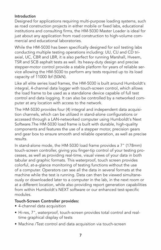
IntroductionDesigned for applications requiring multi-purpose loading systems, such as road construction projects in either mobile or fixed labs, educational institutions and consulting firms, the HM-5030 Master Loader is ideal for just about any application from road construction to high-volume com-mercial and educational laboratories.
While the HM-5030 has been specifically designed for soil testing labs conducting multiple testing operations including: UU, CU and CD tri-axial, UC, CBR and LBR, it is also perfect for running Marshall, Hveem, TSR and SCB asphalt tests as well. Its heavy-duty design and precise stepper-motor control provide a stable platform for years of reliable ser-vice allowing the HM-5030 to perform any tests required up to its load capacity of 11000 lbf (50kN).
Like all elite series load frames, the HM-5030 is built around Humboldt's integral, 4-channel data logger with touch-screen control, which allows the load frame to be used as a standalone device capable of full test control and data logging. It can also be controlled by a networked com-puter at any location with access to the network.
The HM-5030 provides four (4) integral and independent data acquisi-tion channels, which can be utilized in stand-alone configurations or accessed through a LAN-networked computer using Humboldt's Next Software.The HM-5030 load frame is built with durable, high-quality components and features the use of a stepper motor, precision gears and gear box to ensure smooth and reliable operation, as well as precise results.
In stand-alone mode, the HM-5030 load frame provides a 7" (178mm) touch-screen controller, giving you finger-tip control of your testing pro-cesses, as well as providing real-time, visual views of your data in both tabular and graphic formats. This waterproof, touch screen provides colorful, at-a-glance monitoring of testing functions without the use of a computer. Operators can see all the data in several formats at the machine while the test is running. Data can then be viewed simultane-ously or downloaded later to a computer in the lab, in the next room or at a different location, while also providing report generation capabilities from within Humboldt's NEXT software or our enhanced test-specific modules.
Touch-Screen Controller provides:• 4-channel data acquisition
• Hi-res, 7", waterproof, touch-screen provides total control and real-time graphical display of tests
• Machine /Test control and data acquisition via touch-screen
8
• Control up to 4 different tests at the same time
• Calibration of channels to load cells, transducers and other suitable instruments
• Real-time graphical chart and numerical display of tests via touch-screen display
• Effective sampling rate of 50 readings per second• Stores up to 1000 tests with 3000 points per test• 2 USB ports. One in front for data transfer and the rear port is for
powering a wireless access point.• When operated from a networked computer the NEXT software pro-
vides robust machine and test control, as well as report generation. It also provides the ability to control and monitor multiple machines from a single computer.
Humboldt's NEXT software provides:• Machine control, and data acquisition via networked computer • Provides the ability to use Next Software's, advanced test-specific
modules• Real-time graphical chart and numerical display of tests via computer
display• Effective sampling rate of 50 readings per second• Stores unlimited tests with up to 3000 points per test.• Up to 255 individual tests can be run simultaneously from a single PC• Advanced, test-specific modules are available, which provide all the
calculations and graphs required per testing standards• Provides advanced graphing capabilities• Provides full-unit customization• Reports can also be exported to Excel or a CSV file, if desired, and,
we can provide custom integration/export solutions for LIMS, EQuIS, gINT, etc.
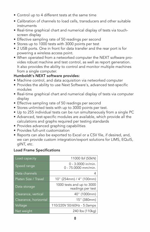
Load Frame Specifications
Load capacity 11000 lbf (50kN)
Speed range 0 - 3.0000 in/min.0 - 75.0000 mm/min.
Data channels 4
Platen Size / Travel 10" (254mm) / 4" (100mm)
Data storage 1000 tests and up to 3000 readings per test
Clearance, vertical 40" (1000mm)
Clearance, horizontal 15" (380mm)
Voltage 110/220V 50/60Hz - 5.0amps
Net weight 240 lbs (110kg)

9
Controller SpecificationsSpecifications for the touch-screen controller, instrumentation and data acquisition used with Humboldt Elite series load frames
Display 7" (178mm) VGA (480 x 800) Resistive-touch screen
Real-time test data Graphic and tabulation
Processor Dual 32-bit ARM
RAM 64MB
Memory, non-volatile 4GB
Analog to digital converter 24 bit
Data acquisition 4 Channels
Logging speed up to 50 readings per second
Multi-test storage 1000
Points per test 3000
USB port (front)
use to export data and import/export calibration data, also use to provide
external power for optional WIFI adapter
USB port (back) provides external power at the back of the machine
Ethernet connection for network connectivity
Emergency stop Large button
24-bit differentialanalog to digital converter(21 bits @1000 samples/sec.
4
Ambient temperature sen-sor 1
Limit switches 4
Firmware Update Ethernet or flash drive

10
General WarningsSafety WarningsOperators should take care to operate this machine under maximum load restrictions. The machine is programmed at the factory to provide safety shutdown if the upper or lower maximum travel is exceeded, as well as if the upper instrument calibration is exceeded.
Electrical WarningsTypically, there is no reason for the operator to open the machine. However, if the customer’s engineers attempt to change settings to the circuit board connected to the back panel, the machine must first be unplugged. Unplugging the internal connection to the back panel circuit board while the machine is under power will result in permanent dam-age to the circuit board.
Manufacturer's Rights and Responsibilities Software Copyright
COPYRIGHT NOTICE©2016 HUMBOLDT Mfg. Co. All Rights Reserved. This manual or
parts thereof may not be reproduced in any form without the expressed written permission of HUMBOLDT Mfg. Co.
UNPUBLISHED LICENSED PROPRIETARY WORK ©2016 HUMBOLDT Mfg. Co.
The programmable, read-only memory, integrated circuit package contained in this equipment and covered with a copyright notice label contains proprietary and confidential software, which is the sole property of HUMBOLDT MFG. CO. It is licensed for use by the original purchaser of this equipment for a period of 99 years. Transfer of the license can be obtained by a request, in writing, from HUMBOLDT MFG. CO.
With the exception of HUMBOLDT Authorized Service Facilities, you may not copy, alter, de-compile, or reverse assemble the software in any fashion except as instructed in this manual. US copyright laws, trade-mark laws, and trade secrets protect the materials. Any person(s) and /or organizations that attempt or accomplish the above violation or know-ingly aid or abet the violation by supplying equipment or technology will be subject to civil damages and criminal prosecution.With the exception of HUMBOLDT Authorized Service Facilities, you may not copy, alter, de-compile, or reverse assemble the software in any fashion except as instructed in this manual. U.S. copyright laws, trademark laws, and trade secrets protect the materials.

11
Any person(s) and /or organizations that attempt or accomplish the above violation or knowingly aid or abet the violation by supplying equipment or technology will be subject to civil damages and criminal prosecution.
Important NoticeThe information contained herein is supplied without representation or warranty of any kind. Humboldt Mfg. Co. therefore assumes no respon-sibility and shall have no liability, consequential or otherwise, of any kind arising from the use of the described equipment contained in this manual.
Updated ProductsThe manufacturer reserves the right to change or modify product design or construction without prior notice and without incurring any obliga-tion to make such changes and modifications on products previously or subsequently sold.
Fitness for ApplicationThe manufacturer makes no recommendations or claims regarding fit-ness for applications other than the specific tests as defined in this User Guide.
UnpackingInitial inspection should include checking for physical damage during shipping and obvious external damage to the product.
Package contents are defined by your packing list. Each Loader is con-figured according to customer specifications. In your inspection, make certain that the contents of your shipment match the documentation provided by your packing list.
Place unit on a flat, smooth surface and use leveling feet (supplied) and a bubble level to ensure that the unit is level side-to-side and back-to-front.
12
1
Quick Start GuideStartup Scenarios
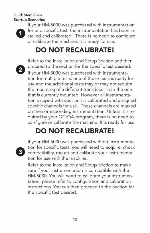
If your HM-5030 was purchased with instrumentation for one specific test: the instrumentation has been in-stalled and calibrated. There is no need to configure or calibrate the machine. It is ready for use.
DO NOT RECALIBRATE! Refer to the Installation and Setup Section and then proceed to the section for the specific test desired.If your HM-5030 was purchased with instrumenta-tion for multiple tests: one of those tests is ready for use and the additional tests may or may not require the mounting of a different transducer than the one that is currently mounted. However all instrumenta-tion shipped with your unit is calibrated and assigned specific channels for use. These channels are marked on the corresponding instrumentation. Unless it is re-quired by your QC/QA program, there is no need to configure or calibrate the machine. It is ready for use.
DO NOT RECALIBRATE! If your HM-5030 was purchased without instrumenta-tion for specific tests: you will need to acquire, check compatibility, mount and calibrate your instrumenta-tion for use with the machine.Refer to the Installation and Setup Section to make sure if your instrumentation is compatible with the HM-5030. You will need to calibrate your instrumen-tation, please refer to configuration and calibration instructions. You can then proceed to the Section for the specific test desired.
2
3

13
Electrical ConnectionsThe HM-5030 is equipped with an internal digital switching power sup-ply, which allows it to be used with most power configurations through-out the world. The unit is supplied with an IEC electrical cord with a standard 110V plug.
The HM-5030 arrives ready for operation. Attach the supplied IEC elec-trical cord to the machine and plug into a standard wall receptacle for use in the United States. For locations other than the U.S., replace the supplied electrical cord with an IEC cord with the correct plug for your application. The supplied cord can also be used by cutting the standard plug from the cord and attaching the correct plug.
Local Area Network ConnectionPlug your machine into the network and refer to the "Network" section. Use a standard CAT 5 or CAT 6 Ethernet cable. If wireless is required, use the 5-volt power USB port located on the back to power a USB ac-cess point.
Power SwitchThe Power Switch is located above the electrical cord inlet in the back panel on the rear of the machine. The Fuse Compartment is located be-tween the electrical cord inlet and the Power Switch. The HM-5030 uses a 10 amp fuse. To begin operation, press the Power Switch.
Figure #3 Power Switch
14
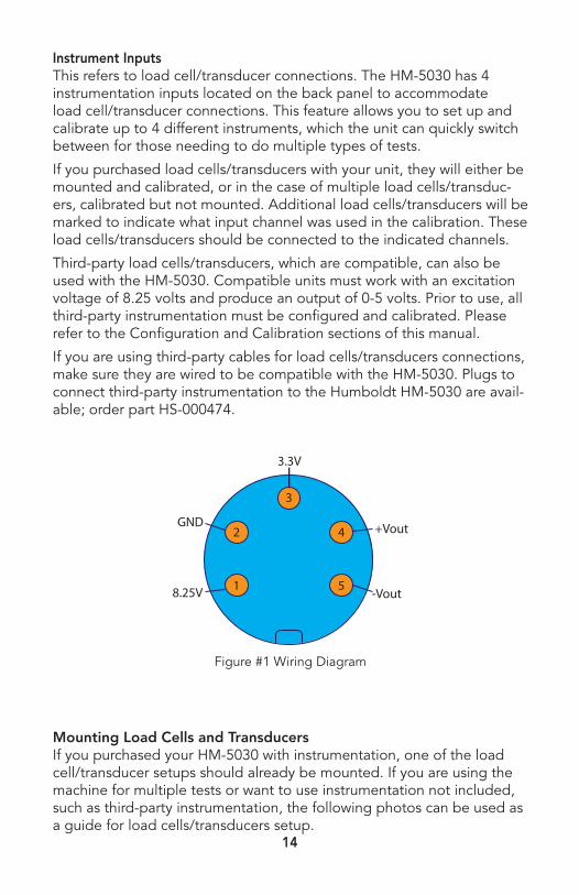
Instrument InputsThis refers to load cell/transducer connections. The HM-5030 has 4 instrumentation inputs located on the back panel to accommodate load cell/transducer connections. This feature allows you to set up and calibrate up to 4 different instruments, which the unit can quickly switch between for those needing to do multiple types of tests.
If you purchased load cells/transducers with your unit, they will either be mounted and calibrated, or in the case of multiple load cells/transduc-ers, calibrated but not mounted. Additional load cells/transducers will be marked to indicate what input channel was used in the calibration. These load cells/transducers should be connected to the indicated channels.
Third-party load cells/transducers, which are compatible, can also be used with the HM-5030. Compatible units must work with an excitation voltage of 8.25 volts and produce an output of 0-5 volts. Prior to use, all third-party instrumentation must be configured and calibrated. Please refer to the Configuration and Calibration sections of this manual.
If you are using third-party cables for load cells/transducers connections, make sure they are wired to be compatible with the HM-5030. Plugs to connect third-party instrumentation to the Humboldt HM-5030 are avail-able; order part HS-000474.
Mounting Load Cells and TransducersIf you purchased your HM-5030 with instrumentation, one of the load cell/transducer setups should already be mounted. If you are using the machine for multiple tests or want to use instrumentation not included, such as third-party instrumentation, the following photos can be used as a guide for load cells/transducers setup.
1
2
3
5
4
8.25V
GND
-Vout
+Vout
3.3V
Figure #1 Wiring Diagram

15
CBR/LBR UnconfinedCompression
Marshall Semi-Circular Bending
ConsolidatedDrained and Undrained
UnconsolidatedUndrained
Typical Setups

16
OperationHome ScreenThis is the screen that appears once your machine is powered on.
1. Options Press this button to select “New Test,” “Current Tests,” “Previous
Tests,” and "System Settings" options.
2. Time This displays the current time, which can be changed under "Date/
Time Settings" or by clicking these numbers.
3. Unique Logger Identification Number This displays the number specific to each logger connected to the
Internet.
Note: Each logger needs a unique identification number.
4. Mute This indicates that sound is disabled.
5. Internet Connectivity This indicates if your machine is connected to the Internet. A red
icon indicates connection to the Internet; a gray icon indicates no connection to the Internet.
6. Network Connectivity This indicates if your machine is connected to the network. A red
icon indicates connection to the network; a gray icon indicates no connection to the network.
7. Motor Control Press this button to display the buttons used to adjust motor direc-
tion and speed. See the image below for details.

17
8. Calibration Indicator This indicates if the input is uncalibrated or displays the calibrated
instrumentation type.
9. Testing Indicator This indicates whether or not a test is currently in progress.
10. Channel This displays the name of the calibrated channel. Four inputs are
available for this machine.
11. Tare/Clear This button can be used to tare the input before testing. Once
pressed, the “Tare” button will change to a “Clear" button, which will remove the applied tare.
12. Calibrated Value This number indicates the calibrated value.
13. Calibration Parameters Calibration parameters will be displayed here. The level of color
indicates calibration parameters. Green indicates within calibration parameters, yellow indicates nearing the end of calibration param-eters, and red indicates over calibration parameters.
Motor Control
1. Direction of Movement Press the up or down arrow to control the direction of motor
movement.
2. Stop Press this to stop motor movement.
18
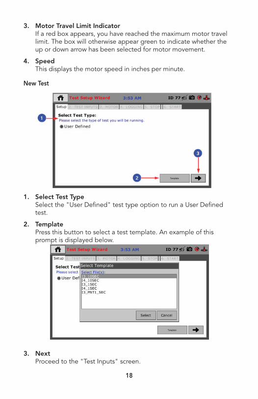
3. Motor Travel Limit Indicator If a red box appears, you have reached the maximum motor travel
limit. The box will otherwise appear green to indicate whether the up or down arrow has been selected for motor movement.
4. Speed This displays the motor speed in inches per minute.
New Test
1. Select Test Type Select the "User Defined" test type option to run a User Defined
test.
2. Template Press this button to select a test template. An example of this
prompt is displayed below.
3. Next Proceed to the "Test Inputs" screen.

19
Test Inputs
1. Select Test Inputs Check the inputs that you would like to use for testing. If a box is
gray, it cannot be checked because the channel is either uncalibrat-ed or being used by another test.
2. Next/Back Proceed to the "Motor" screen or go back to the previous screen.
Motor
1. Select Motor Conditions Select whether or not you would like motor control. If you choose to
select "Motor Control," motor parameter options will be displayed.

20
2. Select Motor Parameters Use the drop-down menu to select if you would like the motor
direction to be up or down. Set your desired motor speed in inches per minute via the screen that will pop up once the "Speed" box is touched. The motor speed cannot exceed 2 inches (or 50.8 mm) per minute. This screen includes arrows to move between decimal places. Click the button when finished.
3. Return Home Check this box if you would like the motor to return to its start-
ing position after the test is complete. If not, the motor will remain where it is when the test is complete.
4. Next/Back Proceed to the "Loggings" screen or go back to the previous
screen.
Loggings
1. Select Logger Conditions Choose how you would like the test to record data. Available op-
tions are "Interval Logging," "Interval Logging Table," "Linear Time Interval," and "Elapsed Time Table."
2. Next/Back Proceed to the "Stop" screen or go back to the previous screen.
21
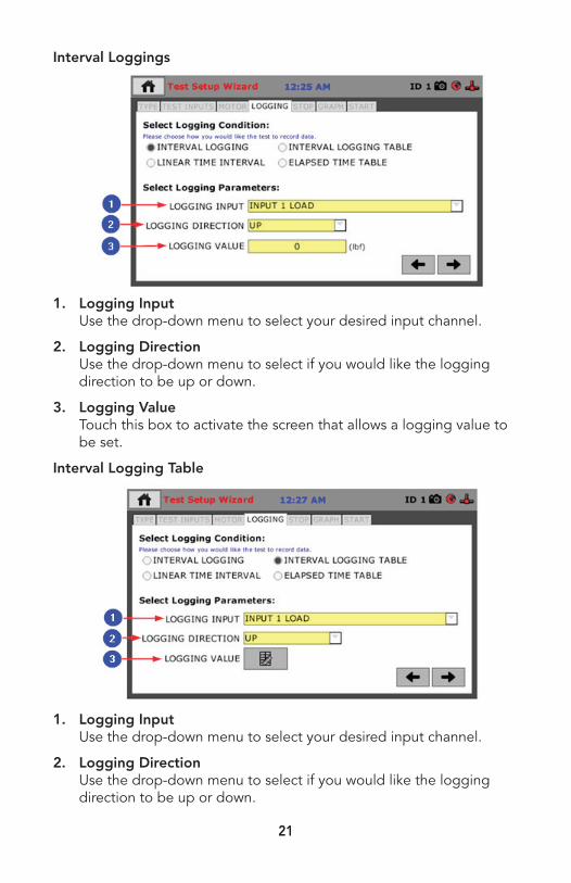
Interval Loggings
1. Logging Input Use the drop-down menu to select your desired input channel.
2. Logging Direction Use the drop-down menu to select if you would like the logging
direction to be up or down.
3. Logging Value Touch this box to activate the screen that allows a logging value to
be set.
Interval Logging Table
1. Logging Input Use the drop-down menu to select your desired input channel.
2. Logging Direction Use the drop-down menu to select if you would like the logging
direction to be up or down.
22
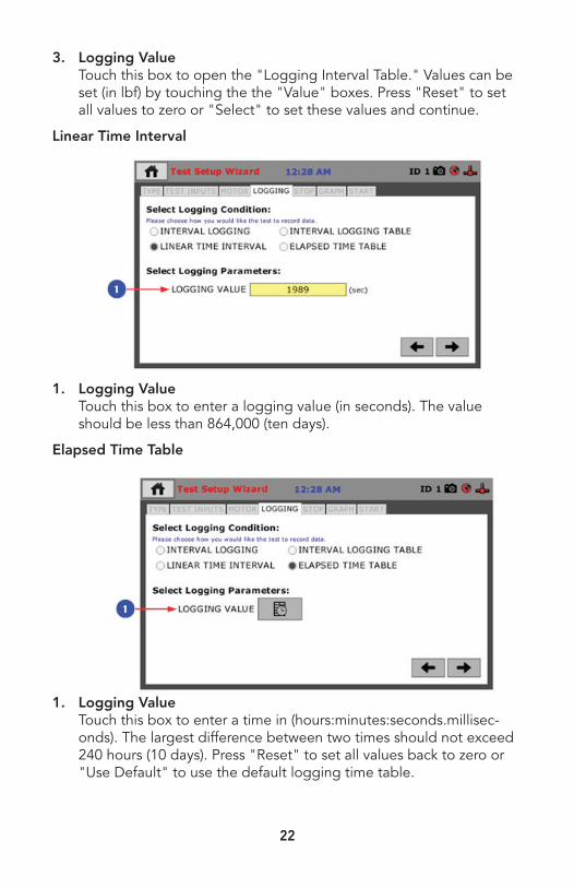
3. Logging Value Touch this box to open the "Logging Interval Table." Values can be
set (in lbf) by touching the the "Value" boxes. Press "Reset" to set all values to zero or "Select" to set these values and continue.
Linear Time Interval
1. Logging Value Touch this box to enter a logging value (in seconds). The value
should be less than 864,000 (ten days).
Elapsed Time Table
1. Logging Value Touch this box to enter a time in (hours:minutes:seconds.millisec-
onds). The largest difference between two times should not exceed 240 hours (10 days). Press "Reset" to set all values back to zero or "Use Default" to use the default logging time table.

23
Stop
1. Select Stop Condition Choose how you would like the test to stop. Options include:
"Greater Than," "Distance (Up)," "Percent Strain," "Less Than," "Distance (Down)," Percent Stress Drop," "Time Delay," "Percent Drop," and "Operator Stop."
2. Next/Back Proceed to the "Graph" screen or go back to the previous screen.
Greater Than
1. Stop Input Choose the input channel that you would like to be involved with
stop parameters.
2. Stop Value Set the maximum value you would like the test to reach before it
stops.

24
Distance (Up)
1. Stop Input Choose the input channel that you would like to be involved with
stop parameters.
2. Stop Value Set the sensor travel distance up from the start of the test.
Percent Strain
1. Stop Input Choose the input channel that you would like to be involved with
stop parameters.
2. Stop Value Percent strain is calculated using the specimen height. The test will
stop when the current calculated percent strain is greater than the value you entered.

25
Less Than
1. Stop Input Choose the input channel that you would like to be involved with
stop parameters.
2. Stop Value Set the minimum value you would like the test to reach before it
stops.
Distance (Down)
1. Stop Input Choose the input channel that you would like to be involved with
stop parameters.
2. Stop Value Set the sensor travel distance down from the start of the test

26
Percent Stress Drop
1. Stop Input Choose the input channel that you would like to be involved with
stop parameters.
2. Stop Value Enter the percent drop in stress. The percent stress drop is calculat-
ed in real time; the test will stop when the calculated percent stress drop is less than the percentage entered.
Time Delay
1. Stop Value Enter the amount of seconds at which you would like the test to
stop.
27
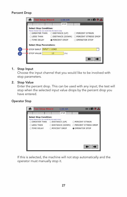
Percent Drop
1. Stop Input Choose the input channel that you would like to be involved with
stop parameters.
2. Stop Value Enter the percent drop. This can be used with any input; the test will
stop when the selected input value drops by the percent drop you have entered.
Operator Stop
If this is selected, the machine will not stop automatically and the operator must manually stop it.
28
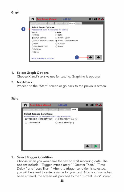
Graph
1. Select Graph Options Choose X and Y axis values for testing. Graphing is optional.
2. Next/Back Proceed to the "Start" screen or go back to the previous screen.
Start
1. Select Trigger Condition Choose when you would like the test to start recording data. The
options include: "Trigger Immediately," "Greater Than," "Time Delay," and "Less Than." After the trigger condition is selected, you will be asked to enter a name for your test. After your name has been entered, the screen will proceed to the "Current Tests" screen.
29
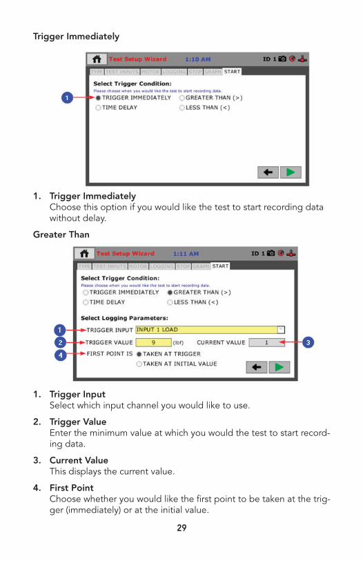
Trigger Immediately
1. Trigger Immediately Choose this option if you would like the test to start recording data
without delay.
Greater Than
1. Trigger Input Select which input channel you would like to use.
2. Trigger Value Enter the minimum value at which you would the test to start record-
ing data.
3. Current Value This displays the current value.
4. First Point Choose whether you would like the first point to be taken at the trig-
ger (immediately) or at the initial value.

30
Time Delay
1. Trigger Value Enter the value in seconds after which you would like the test to
start recording data.
Less Than
1. Trigger Input Select which input channel you would like to use.
2. Trigger Value Enter the maximum value at which you would the test to start re-
cording data.
3. Current Value This displays the current value.
4. First Point Is Choose whether you would like the first point to be taken at the trig-
ger (immediately) or at the initial value.
31
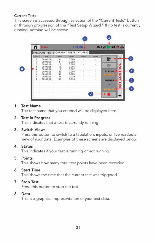
Current TestsThis screen is accessed through selection of the “Current Tests” button or through progression of the “Test Setup Wizard.” If no test is currently running, nothing will be shown.
1. Test Name The test name that you entered will be displayed here.
2. Test in Progress This indicates that a test is currently running.
3. Switch Views Press this button to switch to a tabulation, inputs, or live readouts
view of your data. Examples of these screens are displayed below.
4. Status This indicates if your test is running or not running.
5. Points This shows how many total test points have been recorded.
6. Start Time This shows the time that the current test was triggered.
7. Stop Test Press this button to stop the test.
8. Data This is a graphical representation of your test data.

32
Graph View
Live Readouts View
Previous TestsOnce the test stops or is manually stopped, the screen will move to the “Previous Tests” screen. This screen can also be accessed by selecting the “Previous Tests” button.

33
Tabulation view and graph view are available for previous tests.
1. Choose Test Press this button to view a list of previous tests. Details are ex-
plained below.
2. Switch Views Press this button to switch between a tabulation and graph view of
your data.
3. Test Actions Press this button to export a test to a connected USB flash drive or
generate a setup template from this test.
4. Start Press this button to begin the test wizard for a new test. If the "Fast
Testing" option is enabled on the "Specimen Parameters" screen, a duplicate test of your last test will automatically begin.
5. Points This displays how many points have been recorded.
6. Delete Test Press this button to delete a test.
Choose Test
[Image "ChooseTest" here]
1. Choose Test Press this button to access a list of previous tests.
2. Previous Tests Choose a previous test by clicking one of the test names.
34
3. Select Press “Select” to view the test.
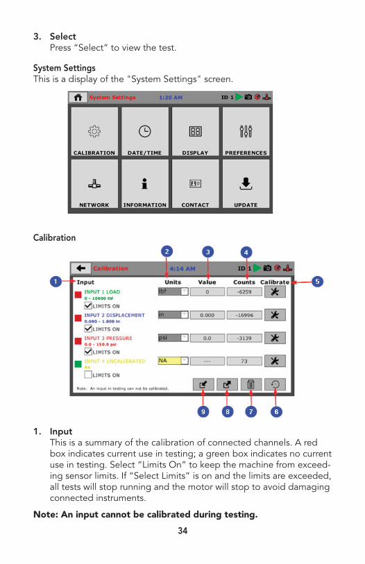
System SettingsThis is a display of the "System Settings" screen.
Calibration
[Image "Calibration" here]
1. Input This is a summary of the calibration of connected channels. A red
box indicates current use in testing; a green box indicates no current use in testing. Select “Limits On” to keep the machine from exceed-ing sensor limits. If “Select Limits” is on and the limits are exceeded, all tests will stop running and the motor will stop to avoid damaging connected instruments.
Note: An input cannot be calibrated during testing.

35
2. Units The display units of calibration instrument can be customized. Avail-
able options include [kN, lbf, and N] for load and [cm, in, and mm] for penetration.
3. Value This displays the current calibration value. If it is not calibrated, the
value will read “N/A.”
4. Counts This displays current input counts.
5. Calibrate Select this button to perform or modify calibration.
6. Restore Factory Calibration Select this button to restore factory calibration. You will see a display
of the current value with system calibration and the current value with factory calibration. Beside each is the option to select for res-toration, and at the bottom of the page is an option to restore all. Press the “restore factory calibration” button to restore the factory calibration.
7. Delete Calibration Press this button to select calibrations to delete.
8. Export Calibration to USB Press this button to select calibrations to export to USB.
9. Import Calibration from USB Press this button to select calibrations to import from USB. An ex-
ample of the import prompt is displayed below.

36
Sensor DetailsThis screen is accessed through selection of the “Calibration” button, then “Calibrate.”
1. Input Type For a CBR test, the types will always be load and displacement. For
other tests, available options include displacement, pressure, and volume.
2. Capacity This refers to the maximum sensor capacity.
3. Full Scale Output This can be found on the sensor specifications sheet or, if not known,
can be left at 0. If a number other than 0 is entered, your machine will automatically generate a 2 point calibration. If you would like to do a manual calibration, leave the number at 0.
4. Next Press this button to continue to “Limits" screen. Fully unload the
attached sensor to allow for optimum configuration of the channel, then fully load it to complete configuration.

37
LimitsThis screen is accessed through selection of the “Calibration” button, then after progression through the “Sensor Details” screen.
1. Calibration Limit The calibration limit cannot exceed sensor capacity unless limits are
turned off. The number of significant digits (digits after the decimal) is how many digits will be available in calibrated readings. A window will open to set the calibration limit. Use the arrow buttons to make corrections, then press the button with the check when you are done.
Note: Significant digits make readings more precise. A displace-ment calibration must have at least 3 significant digits for the test to run correctly.
2. Limits On Select this box to turn limits on/off. If limits are turned off, the cali-
bration limit can exceed sensor capacity.
Note: Accuracy cannot be guaranteed if calibration limit is exceeded.
3. Calibration Method Select “Per FS Output” to automatically do a 2 point calibration.
More information on FS Output can be found in the"Sensor Details" section.
Select “Multi-Point Curve” to do a manual entry for calibration. If your output is at 0 and “Per FS Output” is chosen as the calibration method, your machine will prompt to correct the calibration meth-od. Correct the calibration method by selecting “Multi-Point Curve” or entering a value besides 0.

38
4. Back or Next Use the left arrow to return to the previous screen, “Sensor Details.”
Use the right arrow to continue to the “Multi Point" screen.
Multi PointThis screen is accessed through selection of the “Calibration” but-ton, then after progression through the “Sensor Details” and “Limits” screens.
1. Point This is an index of test points. A minimum of 2 points are required
for a successful calibration.
2. Applied This column corresponds with the calibration type. Manual entry of
applied values allows for calibration of negative values.
3. A/D Counts This column corresponds to the entry method; changing the entry
method changes how registered values are entered.
4. Entry Method Select “Quick Click” to prompt for the applied, or calibrated, value.
Select “Manual Entry” to manually enter applied/registered values.
Note: If “Manual Entry” is selected, all appropriate cells of the calibration table must be filled. The number of appropriate cells depends on your calibration type.
5. Calibration Type This gives the option for a 1 point calibration, 5 point calibration,
10 point calibration, or custom calibration. If a point calibration is

39
selected, your machine will automatically fill the applied column in increments corresponding to your set calibration limit. The custom setting allows entry for any number of calibration points between 1-10 in addition to a 0 point.
6. Set Point/Clear Point Press this button to reset or manually set applied counts.
7. Back or Next Use the left arrow to return to the previous screen, “Limits.” Use the
right arrow to continue to the “Name" screen.
Below are examples of calibration options.
1 Point
5 Point

40
10 Point
Custom
NameThis screen is accessed through selection of the “Calibration” button and after progression through the “Sensor Details,” “Limits,” and “Multi Point” screens.
41
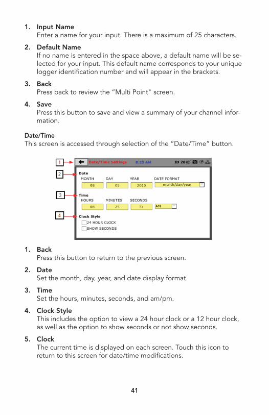
1. Input Name Enter a name for your input. There is a maximum of 25 characters.
2. Default Name If no name is entered in the space above, a default name will be se-
lected for your input. This default name corresponds to your unique logger identification number and will appear in the brackets.
3. Back Press back to review the “Multi Point" screen.
4. Save Press this button to save and view a summary of your channel infor-
mation.
Date/TimeThis screen is accessed through selection of the “Date/Time” button.
1. Back Press this button to return to the previous screen.
2. Date Set the month, day, year, and date display format.
3. Time Set the hours, minutes, seconds, and am/pm.
4. Clock Style This includes the option to view a 24 hour clock or a 12 hour clock,
as well as the option to show seconds or not show seconds.
5. Clock The current time is displayed on each screen. Touch this icon to
return to this screen for date/time modifications.
42
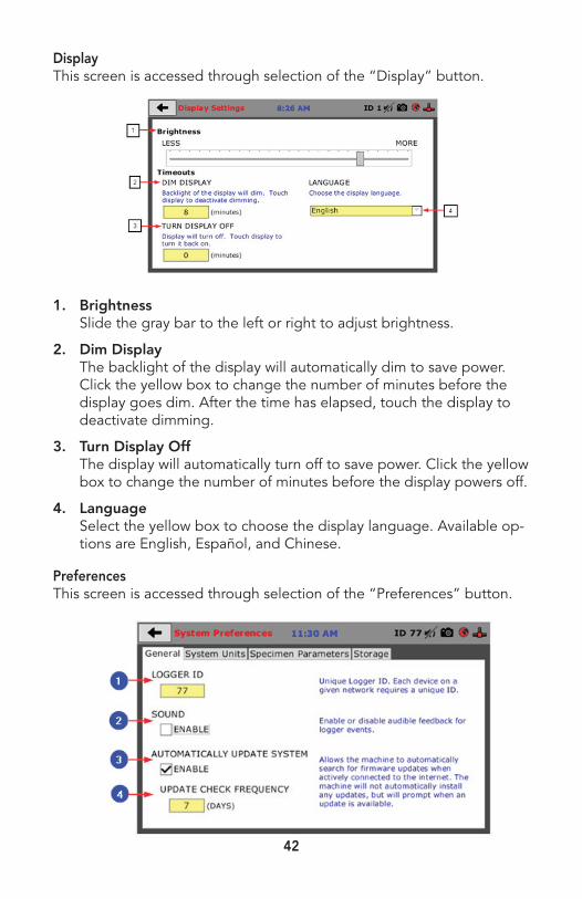
DisplayThis screen is accessed through selection of the “Display” button.
1. Brightness Slide the gray bar to the left or right to adjust brightness.
2. Dim Display The backlight of the display will automatically dim to save power.
Click the yellow box to change the number of minutes before the display goes dim. After the time has elapsed, touch the display to deactivate dimming.
3. Turn Display Off The display will automatically turn off to save power. Click the yellow
box to change the number of minutes before the display powers off.
4. Language Select the yellow box to choose the display language. Available op-
tions are English, Español, and Chinese.
PreferencesThis screen is accessed through selection of the “Preferences” button.

43
1. Logger ID Each logger who is connected to the network needs a unique identi-
fication number. This number can be between 1-245.
2. Sound Enable or disable audio feedback for logger events.
3. Automatically Update System This option allows the machine to automatically search for firmware
updates when actively connected to the Internet. The machine will not automatically install updates; it will prompt when an update is available.
4. Update Check Frequency This number represents the frequency with which the machine
checks for updates.
System UnitsThis screen is accessed through selection of the "System Settings" but-ton, then the “Preferences" button, then “System Units.”
1. Ambient Temperature View current ambient temperature and select desired units (Fahren-
heit or Celsius) for temperature recording.
2. Motor Speed Unit Set desired speed units for motor control (in/min or mm/min).
Specimen ParametersThis screen is accessed through selection of the "System Settings" but-ton, then the “Preferences" button, then “Specimen Parameters.”

44
1. Specimen Height Set the specimen height that will be used for any and all testing
calculations.
2. Specimen Diameter Set the specimen diameter that will be used for any and all testing
calculations.
3. Fast Testing Enable this option to automatically rerun the last test. A new name
will be provided based on the previous test name. If this option is enabled, pushing the "Start" button on the "Previous Tests" screen will begin this duplicate test.
StorageThis screen is accessed through selection of the "System Settings" but-ton, then the “Preferences" button, then “Storage.”

45
1. Test Storage Limit Set the number of previously run tests to be available on the “Previ-
ous Tests” screen. This number can be between 10-50.
2. Recycled Tests This refers to previously run tests that are not displayed in the “Pre-
vious Tests” window. These tests are not deleted; they are recycled for later use. Select this button to view/export/delete recycled tests.
3. Test Templates Select this button to delete test templates that have been created.
NetworkThis screen is accessed through selection of the “Network” button.
1. DHCP Select this to enable/disable the Dynamic Host Configuration
Protocol. If enabled, your machine will pick up IP information from your router. If disabled, you will need to manually enter the network information.
2. IP Information The IP address must be unique for each machine.
3. Local Status This indicates the status of the local network connection.
4. Internet Status This indicates your machine’s ability to connect to the Internet.
Note: If you are experiencing issues with any connections, please contact your IT department for assistance.
46
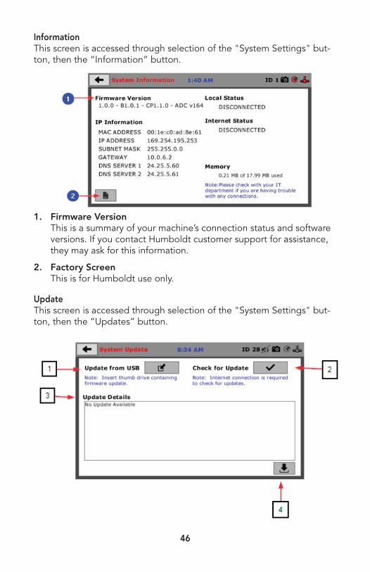
InformationThis screen is accessed through selection of the "System Settings" but-ton, then the “Information” button.
1. Firmware Version This is a summary of your machine’s connection status and software
versions. If you contact Humboldt customer support for assistance, they may ask for this information.
2. Factory Screen This is for Humboldt use only.
UpdateThis screen is accessed through selection of the "System Settings" but-ton, then the “Updates” button.
[Image "UpdateScreen" here]
1. Update from USB
Software updates for your machine can be downloaded from www.1.
47
1. Update from USB Software updates for your machine can be downloaded from www.
humboldtmfg.com. Insert a thumb drive with these firmware up-dates and then select this icon. A window will open to select update files. Press "Cancel" to return to the "Updates" screen.
2. Check for Update If your machine is connected to the Internet, the software will auto-
matically check for updates. How often this occurs can be custom-ized under the "Preferences" button. However, you may select this button to force an immediate check for updates.
3. Update Details If updates are downloaded from the Internet, this shows the chang-
es that were made.
4. Multi-File Update This refers to the file extension of an update. Any files on USB that
are valid for this product will be displayed here. Select this button to run updates.
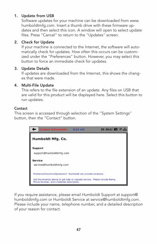
ContactThis screen is accessed through selection of the "System Settings" button, then the “Contact” button.
If you require assistance, please email Humboldt Support at [email protected] or Humboldt Service at [email protected]. Please include your name, telephone number, and a detailed description of your reason for contact.
48
System ResetA reset is available in case of a serious problem in system memory. This will clear all data in memory, including input calibration and configura-tion of all channels. A reset returns the machine to its original factory state. To proceed with this option and reset, hold the “Reset” button on the back of the machine at startup.
SoftwareHumboldt offers comprehensive data reporting software. The software can be used to control the HM-5030, run tests, and collect data in real time. The software also offers detailed reports and interactive graphs. It can be used with the Humboldt Next testing software but will require purchasing the HM-5001SW software module. Additional software mod-ules available for this device include HM-5002SW, HM-5003SW, HM-5004SW, HM-5005SW, and HM-5006SW.
A pre-defined reporting software module and template are available for specific tests. This module provides more control over start and stop conditions for specific tests, as well as provides extended reporting capabilities. Contact Humboldt for more information.
Humboldt Download SoftwareThis software is designed to download tests that have been run directly on the HM-5030. It downloads and saves tests directly to a PC. Cus-tom graphs and reports can be generated and exported into multiple formats.
SupportPhone support is available for general operating questions and trouble-shooting problems between 8am and 5 pm Eastern Time. Please call:
1.800.537.4183
1.919.832.6509 or fax: 1.708.456.0137
For sales and sales-related information, such as available accessories, general sales questions, and pricing, please call:
1.800.544.7220
1.708.456.6300 or fax: 1.708.456.0137


www.humboldtmfg.comHUMBOLDT
Testing Equipment for Construction Materials
Humboldt Mfg. Co.875 Tollgate RoadElgin, Illinois 60123 U.S.A.
U.S.A. Toll Free: 1.800.544.7220 Voice: 1.708.456.6300
Fax: 1.708.456.0137Email: [email protected]
WarrantyHumboldt Mfg. Co. warrants its products to be free from defects in material orworkmanship. The exclusive remedy for this warranty is Humboldt Mfg. Co., factory replacement of any part or parts of such product, for the warranty of this product please refer to Humboldt Mfg. Co. catalog on Terms and Conditions of Sale. The purchaser is responsible for the transportation charges. Humboldt Mfg. Co. shall not be responsible under this warranty if the goods have been improperly maintained, installed, operated or the goods have been altered or modified so as to adversely affect the operation, use performance or durability or so as to change their intended use. The Humboldt Mfg. Co. liability under the warranty contained in this clause is limited to the repair or replacement of defective goods and making good, defective workmanship.


