“ “ AN INVESTIGATION INTO AN INVESTIGATION INTO THE TECHNICAL DESIGN, THE TECHNICAL DESIGN, TRANSIENT STABILITY TRANSIENT STABILITY STUDIES AND MODELLING STUDIES AND MODELLING ISSUES FOR LAND BASED ISSUES FOR LAND BASED WF INTO SMALL ISLAND WF INTO SMALL ISLAND GRID GRID " " Presented by Rohan R.V Seale Presented by Rohan R.V Seale
Transcript
““AN INVESTIGATION INTO AN INVESTIGATION INTO THE TECHNICAL DESIGN,THE TECHNICAL DESIGN,TRANSIENT STABILITY TRANSIENT STABILITY STUDIES AND MODELLING STUDIES AND MODELLING ISSUES FOR LAND BASED ISSUES FOR LAND BASED WF INTO SMALL ISLAND WF INTO SMALL ISLAND
GRIDGRID""
Presented by Rohan R.V SealePresented by Rohan R.V Seale
PROJECT PROJECT OBJECTIVES :OBJECTIVES :
• Develop grid connection requirements and Develop grid connection requirements and standards for BLPC that will permit the standards for BLPC that will permit the development and operation of an efficient, safe, development and operation of an efficient, safe, reliable and well coordinated transmission grid reliable and well coordinated transmission grid system.system.
• Investigate the power quality impact of wind farm Investigate the power quality impact of wind farm on BLPC network.on BLPC network.
• Perform relevant Transient studies to assess the Perform relevant Transient studies to assess the impact due to 24 kv Wind Farm connection on impact due to 24 kv Wind Farm connection on island grid.island grid.
• Assess the overall protection, design and SCADA Assess the overall protection, design and SCADA requirements for integration of a land based wind requirements for integration of a land based wind farm into a small island utility.farm into a small island utility.
BACKGROUND INFORMATIONBACKGROUND INFORMATION• CONNECTION OF WF TO NORTH SUB.CONNECTION OF WF TO NORTH SUB.• NORMALLY WEAK CONNECTION -POTENTIAL NORMALLY WEAK CONNECTION -POTENTIAL
LOW VOLTAGE AT DIST. LEVELLOW VOLTAGE AT DIST. LEVEL• RADIAL LINE WITH SINGLE OHL FEEDRADIAL LINE WITH SINGLE OHL FEED• SECOND UG CABLE FEED DUE IN 2007SECOND UG CABLE FEED DUE IN 2007• ADDITIONAL 2 X 132 KV UG CABLES - 2008ADDITIONAL 2 X 132 KV UG CABLES - 2008• POTENTIAL GEN. SITE DEVELOPMENT IN POTENTIAL GEN. SITE DEVELOPMENT IN
NORTH-ADDITIONAL 4 x 20MW (2009)NORTH-ADDITIONAL 4 x 20MW (2009)
REGENCY PK.
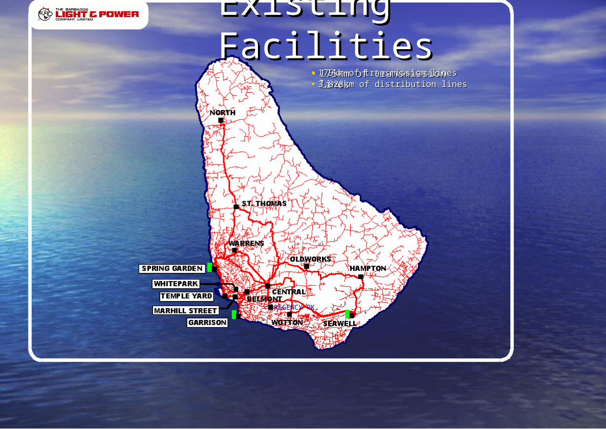
• 175km of transmission lines175km of transmission lines
REGENCY PK.
• 175km of transmission lines175km of transmission lines• 3,828km of distribution lines3,828km of distribution lines
REGENCY PK.
Existing FacilitiesExisting Facilities
BLPC TRANSMISSION BLPC TRANSMISSION SYSTEMSYSTEM
ADVENT OF WT GENERATIONADVENT OF WT GENERATION• Wind generators connect to both the Wind generators connect to both the
distribution & transmission networks .distribution & transmission networks .• An emerging set of renewable energy An emerging set of renewable energy
generation is under construction or in generation is under construction or in planning phase in Caribbean.planning phase in Caribbean.
• The transmission & distribution systems The transmission & distribution systems will require selective reinforcement to will require selective reinforcement to support the volume of renewable support the volume of renewable generation being planned.generation being planned.
• The technical connection requirements for The technical connection requirements for generators connecting to the transmission generators connecting to the transmission or distribution systems are set out in or distribution systems are set out in Industry Codes and Intl. Standards.Industry Codes and Intl. Standards.
• Framework agreements set out Framework agreements set out obligations and contractually binding obligations and contractually binding arrangements between generators & arrangements between generators & Utilities.Utilities.
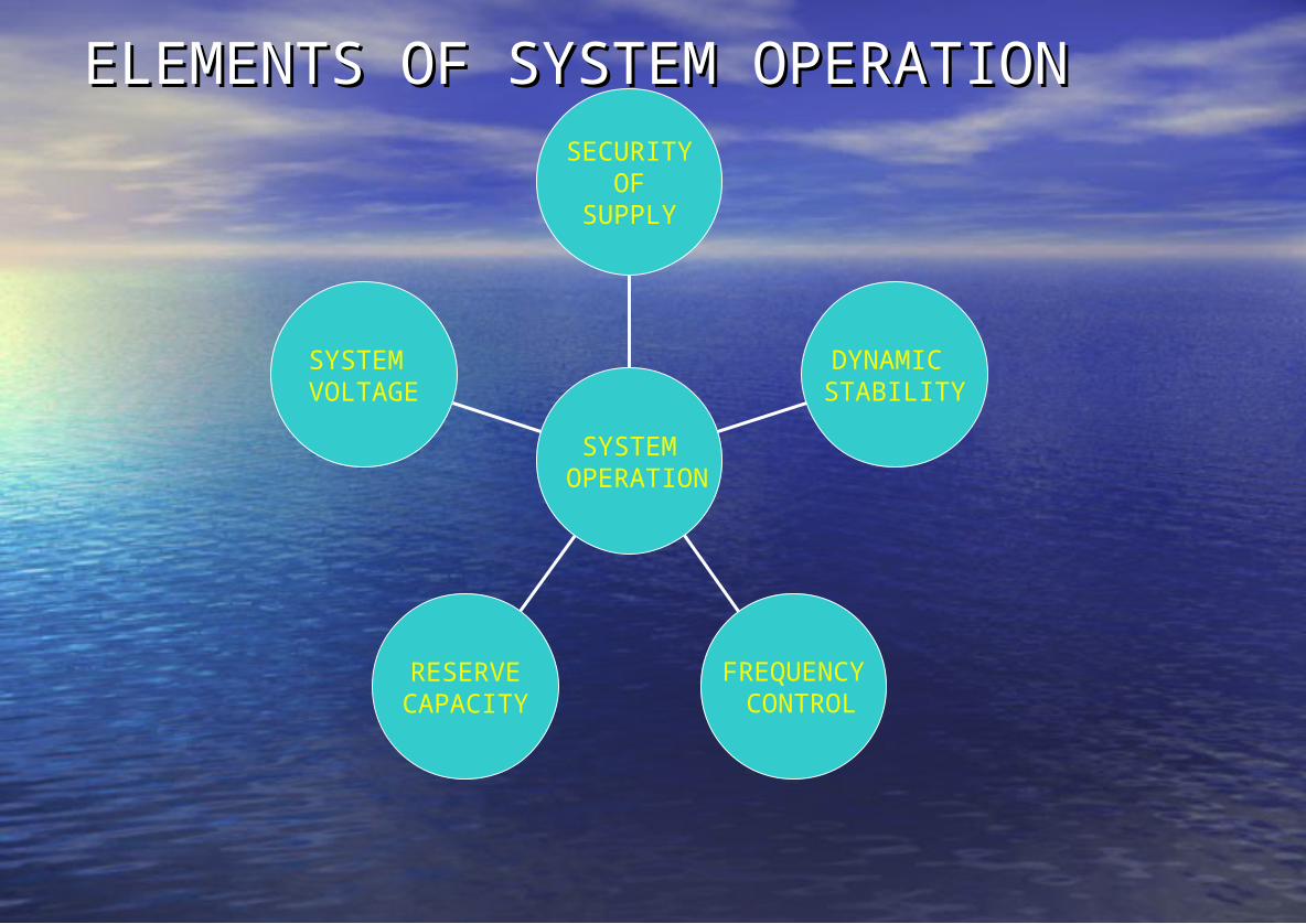
ELEMENTS OF SYSTEM OPERATIONELEMENTS OF SYSTEM OPERATIONSECURITY
OFSUPPLY
DYNAMIC STABILITY
FREQUENCY CONTROL
RESERVECAPACITY
SYSTEM VOLTAGE
SYSTEM OPERATION
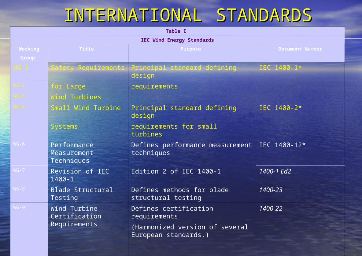
INTERNATIONALINTERNATIONAL STANDARDSSTANDARDSThe status of the IEC standards is provided in Table I.
Table I
IEC Wind Energy Standards
Working Title Purpose Document Number
Group
WG-1 Safety Requirements Principal standard defining design IEC 1400-1* WG-2 for Large requirementsWG-3 Wind Turbines WG-4 Small Wind Turbine Principal standard defining design IEC 1400-2*
Systems requirements for small turbinesWG-6 Performance
Measurement Techniques
Defines performance measurement techniques
IEC 1400-12*
WG-7 Revision of IEC 1400-1 Edition 2 of IEC 1400-1 1400-1 Ed2WG-8 Blade Structural Testing Defines methods for blade structural
testing1400-23
WG-9 Wind Turbine Certification Requirements
Defines certification requirements 1400-22
(Harmonized version of several European standards.)
WG-10 Power Quality Defines power 1400-21
Measurements quality measurement techniques
*Published Standard
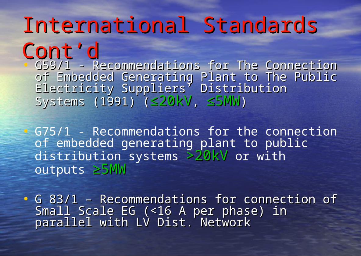
International Standards International Standards Cont’dCont’d• G59/1 - Recommendations for The Connection of G59/1 - Recommendations for The Connection of
Embedded Generating Plant to The Public Embedded Generating Plant to The Public Electricity Suppliers’ Distribution Systems (1991) Electricity Suppliers’ Distribution Systems (1991) ((≤20kV≤20kV, , ≤5MW≤5MW))
• G75/1 - Recommendations for the connection of embedded generating plant to public distribution systems >20kV>20kV or with outputs ≥5MW ≥5MW
• G 83/1 – Recommendations for connection of G 83/1 – Recommendations for connection of Small Scale EG (<16 A per phase) in parallel with Small Scale EG (<16 A per phase) in parallel with LV Dist. NetworkLV Dist. Network
IEEE P 1547-2003 STANDARDIEEE P 1547-2003 STANDARD• Influential standard for interconnection of Influential standard for interconnection of
all forms of DR is IEEE 1547-2003, all forms of DR is IEEE 1547-2003, Standard for Standard for
Interconnecting Distributed Resources with Electric Power SystemsInterconnecting Distributed Resources with Electric Power Systems..• IEEE 1547 is the result of a recent effort IEEE 1547 is the result of a recent effort
by SCC21 to develop a single by SCC21 to develop a single interconnection standard that applies to interconnection standard that applies to all technologies. all technologies.
• IEEE 1547 addresses all types of IEEE 1547 addresses all types of interconnected generation up to 10 MW.interconnected generation up to 10 MW.
• The 1547 standard has benefited greatly The 1547 standard has benefited greatly from earlier utility industry work from earlier utility industry work documented in IEEE and IEC standards documented in IEEE and IEC standards (ANSI- C37 series for protective relaying)(ANSI- C37 series for protective relaying)
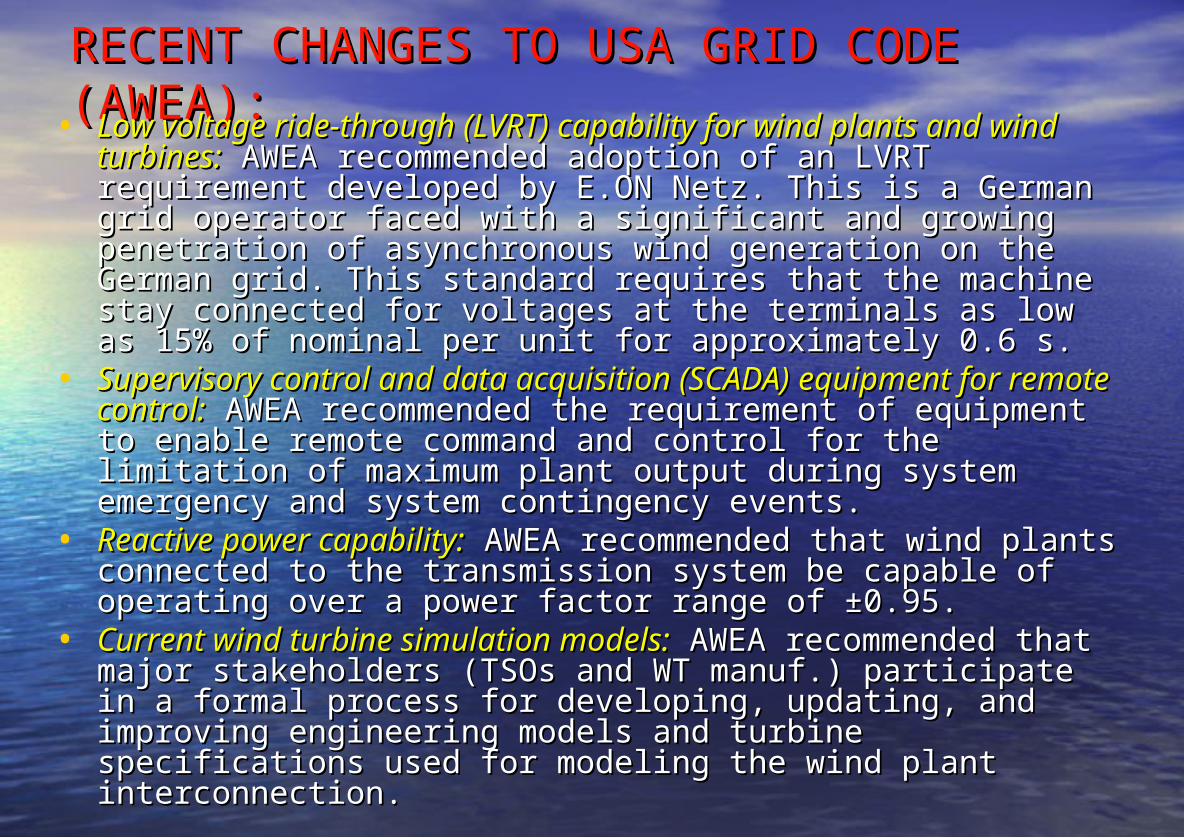
RECENT CHANGES TO USA GRID CODE RECENT CHANGES TO USA GRID CODE (AWEA):(AWEA):• Low voltage ride-through (LVRT) capability for wind plants and Low voltage ride-through (LVRT) capability for wind plants and
wind turbines:wind turbines: AWEA recommended adoption of an LVRT AWEA recommended adoption of an LVRT requirement developed by E.ON Netz. This is a German grid requirement developed by E.ON Netz. This is a German grid operator faced with a significant and growing penetration of operator faced with a significant and growing penetration of asynchronous wind generation on the German grid. This asynchronous wind generation on the German grid. This standard requires that the machine stay connected for voltages standard requires that the machine stay connected for voltages at the terminals as low as 15% of nominal per unit for at the terminals as low as 15% of nominal per unit for approximately 0.6 s. approximately 0.6 s.
• Supervisory control and data acquisition (SCADA)Supervisory control and data acquisition (SCADA) equipment equipment for remote control:for remote control: AWEA recommended the requirement of AWEA recommended the requirement of equipment to enable remote command and control for the equipment to enable remote command and control for the limitation of maximum plant output during system emergency limitation of maximum plant output during system emergency and system contingency events. and system contingency events.
• Reactive power capability:Reactive power capability: AWEA recommended that wind AWEA recommended that wind plants connected to the transmission system be capable of plants connected to the transmission system be capable of operating over a power factor range of ±0.95. operating over a power factor range of ±0.95.
• Current wind turbine simulation models:Current wind turbine simulation models: AWEA recommended AWEA recommended that major stakeholders (TSOs and WT manuf.) participate in a that major stakeholders (TSOs and WT manuf.) participate in a formal process for developing, updating, and improving formal process for developing, updating, and improving engineering models and turbine specifications used for engineering models and turbine specifications used for modeling the wind plant interconnection. modeling the wind plant interconnection.
RECENT CHANGES TO UK GRID RECENT CHANGES TO UK GRID CODECODEThe Grid Code incorporates the technical issues raised by the 3 The Grid Code incorporates the technical issues raised by the 3
Licensees with respect to the connection of windfarms:Licensees with respect to the connection of windfarms:• Fault ride through: Fault ride through: Requirement for generating units to revert to Requirement for generating units to revert to
normal operation when a fault on the network is cleared.normal operation when a fault on the network is cleared.• Power/frequency characteristics:Power/frequency characteristics: Requirement for generating units Requirement for generating units
to be able to deliver power & remain connected to the network to be able to deliver power & remain connected to the network when the system frequency deviates from 50Hz.when the system frequency deviates from 50Hz.
• Frequency control:Frequency control: Requirement for generating plants to be able to Requirement for generating plants to be able to increase/decrease power output with falling or rising frequency.increase/decrease power output with falling or rising frequency.
• Reactive range and voltage control:Reactive range and voltage control: Requirement for generating Requirement for generating plant to be able to supply lagging/leading reactive power and plant to be able to supply lagging/leading reactive power and control the voltage at the grid connection point. control the voltage at the grid connection point.
• Negative phase sequence:Negative phase sequence: The requirement for generating units to The requirement for generating units to be able to withstand negative sequence currents caused by phase be able to withstand negative sequence currents caused by phase voltage unbalance and phase to phase faults.voltage unbalance and phase to phase faults.
WFPS1.4 FAULT RIDE THROUGH REQUIREMENTS
WFPS1.4.1 A Wind Farm Power Station shall remain connected to the Transmission System for
Transmission System Voltage dips on any or all phases, where the TransmissionSystem Voltage measured at the HV terminals of the Grid Connected Transformer
remains above the heavy black line in Figure WFPS1.1.
Connection process overviewConnection process overview
PROJECT PLANNING PHASE
INFORMATION PHASE
DESIGN PHASE
CONSTRUCTION PHASE
TESTING & COMMISSIONING PHASE
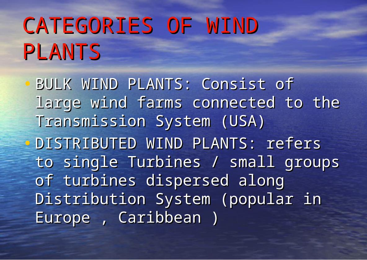
CATEGORIES OF WIND CATEGORIES OF WIND PLANTSPLANTS• BULK WIND PLANTS: Consist of large BULK WIND PLANTS: Consist of large
wind farms connected to the wind farms connected to the Transmission System (USA)Transmission System (USA)
• DISTRIBUTED WIND PLANTS: refers to DISTRIBUTED WIND PLANTS: refers to single Turbines / small groups of single Turbines / small groups of turbines dispersed along Distribution turbines dispersed along Distribution System (popular in Europe , System (popular in Europe , Caribbean )Caribbean )
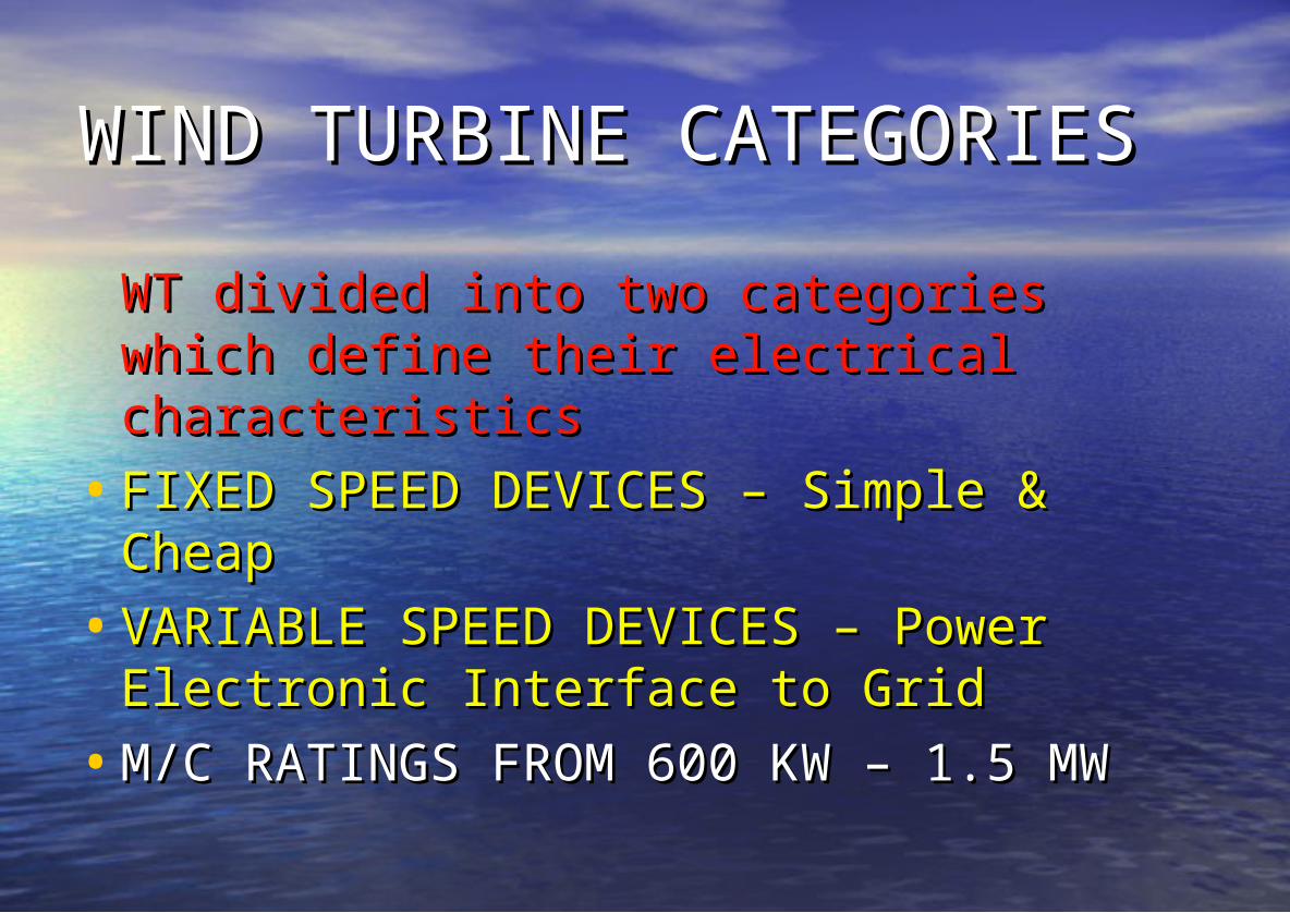
WIND TURBINE CATEGORIESWIND TURBINE CATEGORIESWT divided into two categories which WT divided into two categories which define their electrical characteristicsdefine their electrical characteristics
• FSIG: Standard squirrel-cage FSIG: Standard squirrel-cage induction generator connected induction generator connected directly to the grid:directly to the grid: These machines These machines have a gearbox to match the have a gearbox to match the rotational speed of blades with that rotational speed of blades with that of the generator. Mechanical power of the generator. Mechanical power may be regulated through an may be regulated through an inherent aerodynamic stall inherent aerodynamic stall characteristic of blades or with active characteristic of blades or with active control of blade pitch. control of blade pitch.
• WRIG: Wound-rotor induction WRIG: Wound-rotor induction generator with variable rotor generator with variable rotor resistance:resistance: These machines have a These machines have a gearbox for coupling an electrical gearbox for coupling an electrical generator to a turbine hub. They also generator to a turbine hub. They also have pitch control of blades for have pitch control of blades for maximizing energy capture and maximizing energy capture and controlling turbine speed within range controlling turbine speed within range of the generator and a small range of of the generator and a small range of variable speed operation (e.g., 10% variable speed operation (e.g., 10% of generator synchronous speed). of generator synchronous speed).
These are essentially wound rotor induction These are essentially wound rotor induction machines with variable frequency excitation of machines with variable frequency excitation of the rotor circuit, incorporating rotor current the rotor circuit, incorporating rotor current control via power converter. The rotor circuit control via power converter. The rotor circuit power converter may be four-quadrant, allowing power converter may be four-quadrant, allowing independent control of real and reactive flow in independent control of real and reactive flow in either direction (rotor to grid or grid to rotor), or either direction (rotor to grid or grid to rotor), or unidirectional real power flow (grid to rotor). unidirectional real power flow (grid to rotor). These machines have a gearbox for coupling the These machines have a gearbox for coupling the generator shaft to turbine hub, active control of generator shaft to turbine hub, active control of turbine blade pitch for maximizing production turbine blade pitch for maximizing production and controlling mechanical speed, and variable and controlling mechanical speed, and variable speed operation depending on the rating of speed operation depending on the rating of power converter relative to turbine rating (e.g., power converter relative to turbine rating (e.g., ±30% of generator synchronous speed).±30% of generator synchronous speed).
• Synchronous or induction generator with full-Synchronous or induction generator with full-size power converter:size power converter: In these machines, the In these machines, the generator is coupled to the grid through a fully generator is coupled to the grid through a fully rated ac/dc/ac power converter. They also have rated ac/dc/ac power converter. They also have a gearbox to match generator speed to variable a gearbox to match generator speed to variable rotational speed of blades and variable speed rotational speed of blades and variable speed operation over a wide range, depending on operation over a wide range, depending on electrical generator characteristics. electrical generator characteristics.
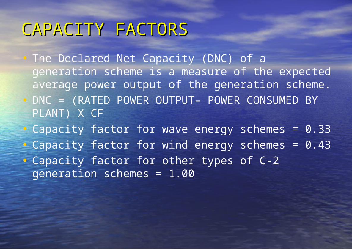
CAPACITY FACTORSCAPACITY FACTORS• The Declared Net Capacity (DNC) of a generation
scheme is a measure of the expected average power output of the generation scheme.
• DNC = (RATED POWER OUTPUT– POWER CONSUMED BY PLANT) X CF
• Capacity factor for wave energy schemes = 0.33• Capacity factor for wind energy schemes = 0.43• Capacity factor for other types of C-2 generation
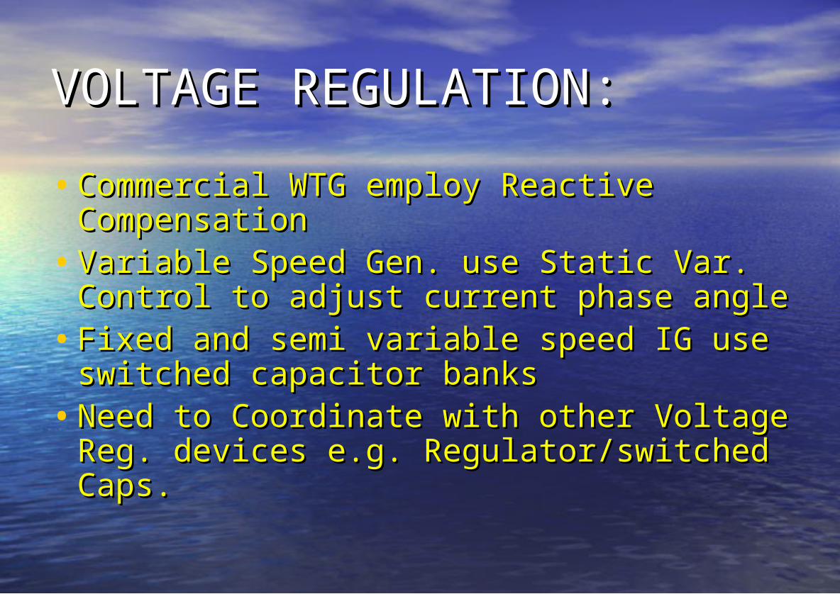
Factors Impacting System Factors Impacting System VoltageVoltage• Local Wind Profile (Speed, Turbulence, Local Wind Profile (Speed, Turbulence,
Shear)Shear)• Size of Wind Turbine to Short Circuit ratioSize of Wind Turbine to Short Circuit ratio• X/R Ratio of systemX/R Ratio of system• Type of WTG and associated Reactive Type of WTG and associated Reactive
Power ControlPower Control• Loading on Distribution FeederLoading on Distribution Feeder
CompensationCompensation• Variable Speed Gen. use Static Var. Variable Speed Gen. use Static Var.
Control to adjust current phase angleControl to adjust current phase angle• Fixed and semi variable speed IG use Fixed and semi variable speed IG use
switched capacitor banksswitched capacitor banks• Need to Coordinate with other Voltage Need to Coordinate with other Voltage
Reg. devices e.g. Regulator/switched Reg. devices e.g. Regulator/switched Caps.Caps.
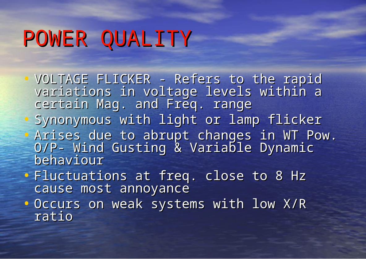
POWER QUALITYPOWER QUALITY• VOLTAGE FLICKER - Refers to the rapid VOLTAGE FLICKER - Refers to the rapid
variations in voltage levels within a certain variations in voltage levels within a certain Mag. and Freq. range Mag. and Freq. range
• Synonymous with light or lamp flickerSynonymous with light or lamp flicker• Arises due to abrupt changes in WT Pow. Arises due to abrupt changes in WT Pow.
• Fluctuations at freq. close to 8 Hz cause Fluctuations at freq. close to 8 Hz cause most annoyancemost annoyance
• Occurs on weak systems with low X/R ratioOccurs on weak systems with low X/R ratio
VOLTAGE FLICKER IMPACTVOLTAGE FLICKER IMPACT• Peculiar to Fixed speed devicesPeculiar to Fixed speed devices• Variable speed WT less likely to cause Variable speed WT less likely to cause
flickerflicker• Wind farm with several turbines less Wind farm with several turbines less
likely to cause flicker as variations of likely to cause flicker as variations of Pow. O/P tend to cancel out.Pow. O/P tend to cancel out.
CAUSES OF FLICKER BY WTGCAUSES OF FLICKER BY WTG• Blade passing of tower results in Blade passing of tower results in
oscillationsoscillations• Variations of wind speedVariations of wind speed• Switching operations- startup & Switching operations- startup &
shutdownshutdown• Recommended limits on flicker in Dist. Recommended limits on flicker in Dist.
Networks addressed in IEC 61400.21Networks addressed in IEC 61400.21
SHORT CIRCUIT SHORT CIRCUIT CONTRIBUTIONCONTRIBUTION • For WTG in 600 kw - 1.3 MW range must For WTG in 600 kw - 1.3 MW range must
consider Fault Contribution consider Fault Contribution • 80-90% of Dist faults are SLG which cause 80-90% of Dist faults are SLG which cause
m/c to receive normal excitation voltagem/c to receive normal excitation voltage• For voltage > 60% treat IG as Synch. m/c. For voltage > 60% treat IG as Synch. m/c.
(Rule of thumb by W. Feero)(Rule of thumb by W. Feero)• Obtain Static Ind. m/c model – more Obtain Static Ind. m/c model – more
accurateaccurate
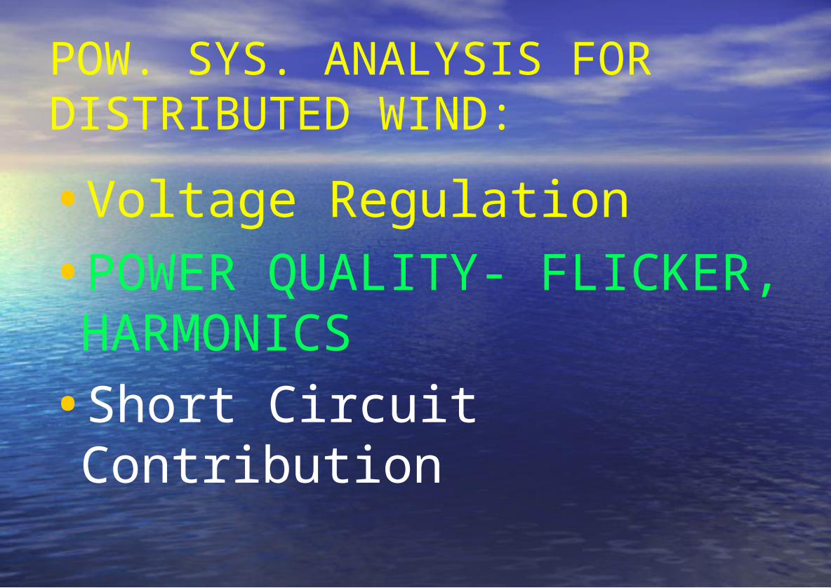
NETWORK EFFECT OF GEN. NETWORK EFFECT OF GEN. TECH.TECH.
EFFECTS DUE TO FAULT EFFECTS DUE TO FAULT CONTRIBUTIONCONTRIBUTION
•REDUCTION OF RELAY REACHREDUCTION OF RELAY REACH•SYMPATHETIC TRIPPING OF SYMPATHETIC TRIPPING OF
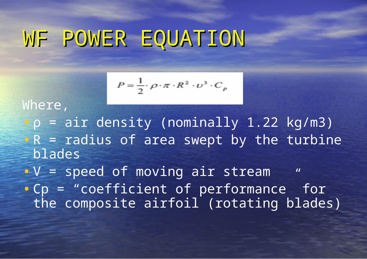
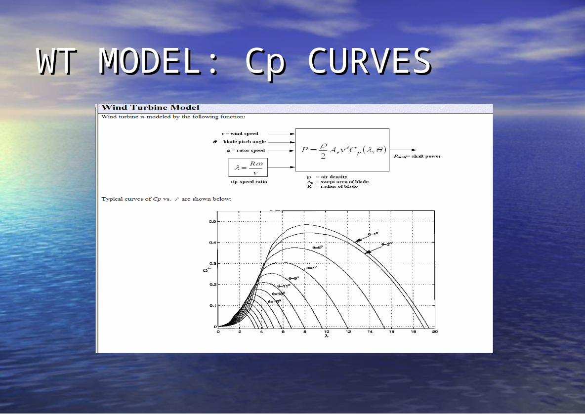
Where,•ρ = air density (nominally 1.22 kg/m3)•R = radius of area swept by the turbine
blades•V = speed of moving air stream•Cp = “coefficient of performance” for the
composite airfoil (rotating blades)
VAR SUPPORTVAR SUPPORT• WIND FARMS TYPICALLY NOT USED TO WIND FARMS TYPICALLY NOT USED TO
PROVIDE VOLTAGE CONTROLPROVIDE VOLTAGE CONTROL• CAN PROVIDE LOCAL VOLTAGE REGULATION CAN PROVIDE LOCAL VOLTAGE REGULATION
FOR WEAK SYSTEMSFOR WEAK SYSTEMS• FLUCTUATING WIND PLANT O/P MEANS AMT. FLUCTUATING WIND PLANT O/P MEANS AMT.
OF REACTIVE POW. REQ’D VARIESOF REACTIVE POW. REQ’D VARIES• FAILURE TO MAINTAIN REACTIVE Q LEADS TO FAILURE TO MAINTAIN REACTIVE Q LEADS TO
VOLTAGE COLLAPSE AS WTG O/P INCREASESVOLTAGE COLLAPSE AS WTG O/P INCREASES
REACTIVE COMPENSATION REACTIVE COMPENSATION TECHNIQUES:TECHNIQUES:• CONSTANT PF - CONSTANT PF - Switched Cap. Banks at each Switched Cap. Banks at each
WTG provide constant PF over range of Gen WTG provide constant PF over range of Gen O/PO/P
• VARIABLE PF – VARIABLE PF – Real time control of each WTG Real time control of each WTG reactive Q production or absorptionreactive Q production or absorption
• SUBS. SWITCHED CAP. BANKS – SUBS. SWITCHED CAP. BANKS – Large Cap Large Cap banks located at interconnection Sub.banks located at interconnection Sub.
• STATCOM – STATCOM – FACTS devices that use voltage FACTS devices that use voltage source converters to provide reactive current.source converters to provide reactive current.
POWER SYSTEM STABILITYPOWER SYSTEM STABILITY• Full Assessment of Network Full Assessment of Network
performance requires study of performance requires study of STEADY STATE and TRANSIENT STEADY STATE and TRANSIENT STABILITYSTABILITY operation operation
• Characteristics of WTG must not Characteristics of WTG must not compromise the stability of Power compromise the stability of Power System following CONTINGENCYSystem following CONTINGENCY
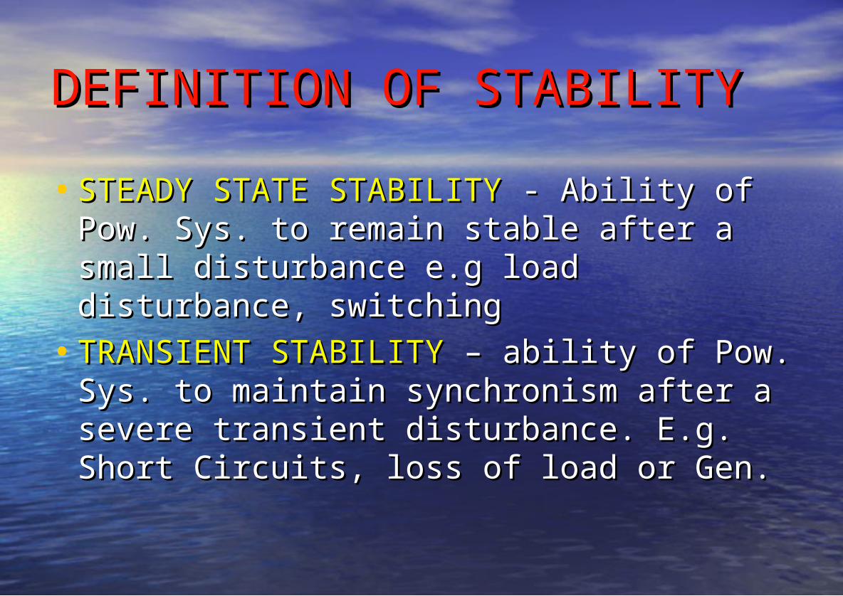
DEFINITION OF STABILITYDEFINITION OF STABILITY• STEADY STATE STABILITYSTEADY STATE STABILITY - Ability of - Ability of
Pow. Sys. to remain stable after a small Pow. Sys. to remain stable after a small disturbance e.g load disturbance, disturbance e.g load disturbance, switchingswitching
• TRANSIENT STABILITYTRANSIENT STABILITY – ability of Pow. – ability of Pow. Sys. to maintain synchronism after a Sys. to maintain synchronism after a severe transient disturbance. E.g. Short severe transient disturbance. E.g. Short Circuits, loss of load or Gen. Circuits, loss of load or Gen.
PURPOSE OF TRANS. STAB. STUDYPURPOSE OF TRANS. STAB. STUDY
• TO PREDICT ABILITY OF GEN. TO RECOVER TO PREDICT ABILITY OF GEN. TO RECOVER AND REMAIN CONNECTED TO POWER SYSTEM AND REMAIN CONNECTED TO POWER SYSTEM AFTER A FAULTAFTER A FAULT
• TO ASSESS INTERACTION OF GENS. AND TO ASSESS INTERACTION OF GENS. AND OTHER ROTATING PLANT (WTG) CONNECTED OTHER ROTATING PLANT (WTG) CONNECTED TO NETWORK AFTER FAULTTO NETWORK AFTER FAULT
• TO ENSURE MINIMUM VOLTAGE TO ENSURE MINIMUM VOLTAGE DISTURBANCE DUE TO LOSS OF DISTURBANCE DUE TO LOSS OF SYNCHRONISMSYNCHRONISM
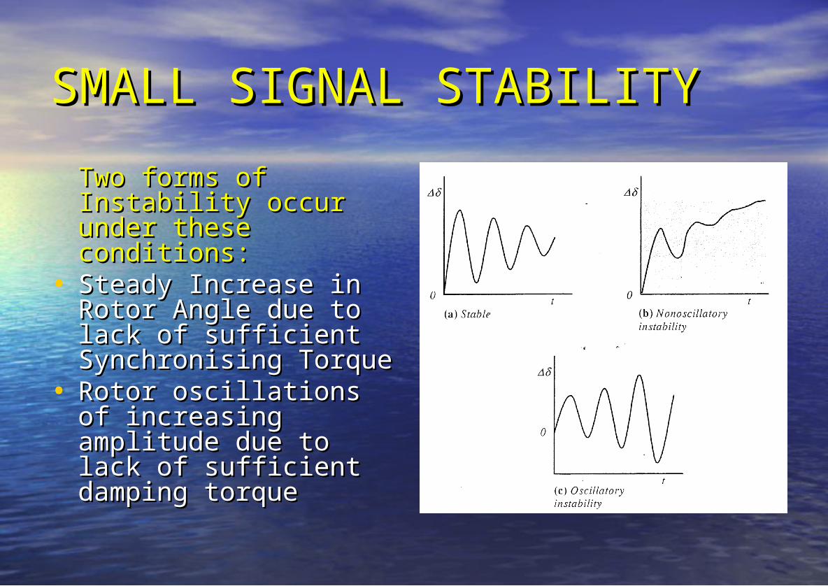
SMALL SIGNAL STABILITYSMALL SIGNAL STABILITYTwo forms of Two forms of Instability occur under Instability occur under these conditions:these conditions:
• Steady Increase in Steady Increase in Rotor Angle due to Rotor Angle due to lack of sufficient lack of sufficient Synchronising TorqueSynchronising Torque
• Rotor oscillations of Rotor oscillations of increasing amplitude increasing amplitude due to lack of due to lack of sufficient damping sufficient damping torquetorque
TRANSIENT STABILITY TRANSIENT STABILITY CONSIDERATIONSCONSIDERATIONS• In large complex power systems In large complex power systems
Transient instability may not always Transient instability may not always occur as first Swing Instability, but occur as first Swing Instability, but may be due to superposition of may be due to superposition of several modes of oscillations.several modes of oscillations.
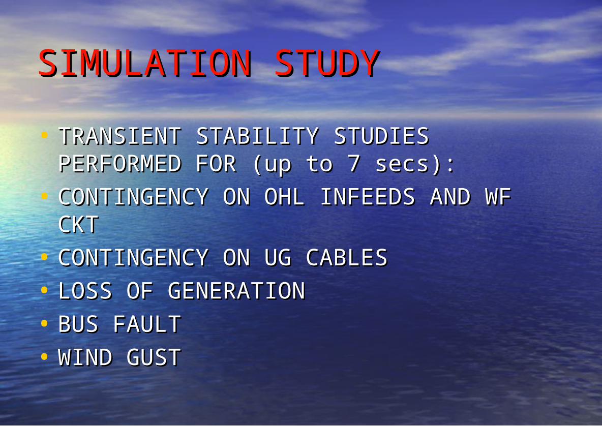
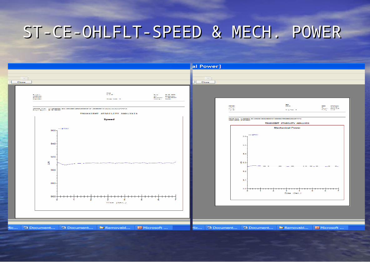
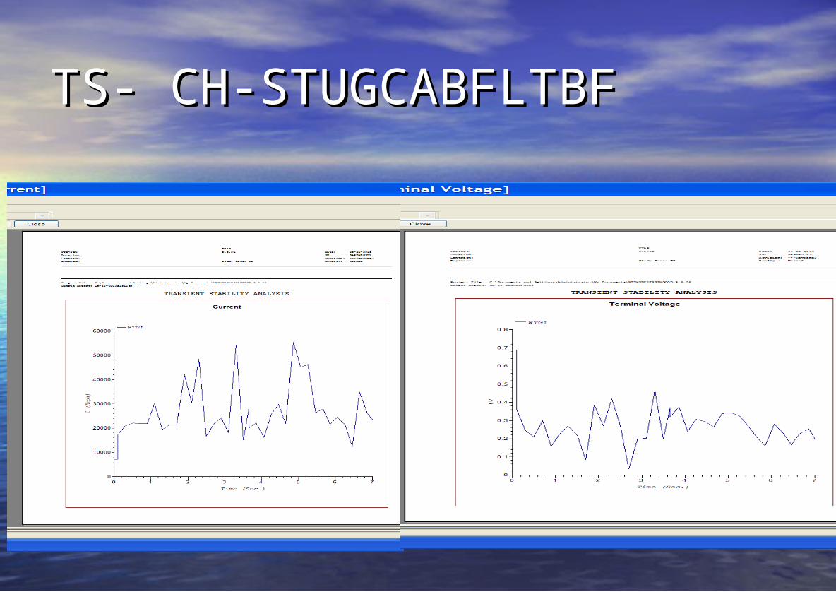
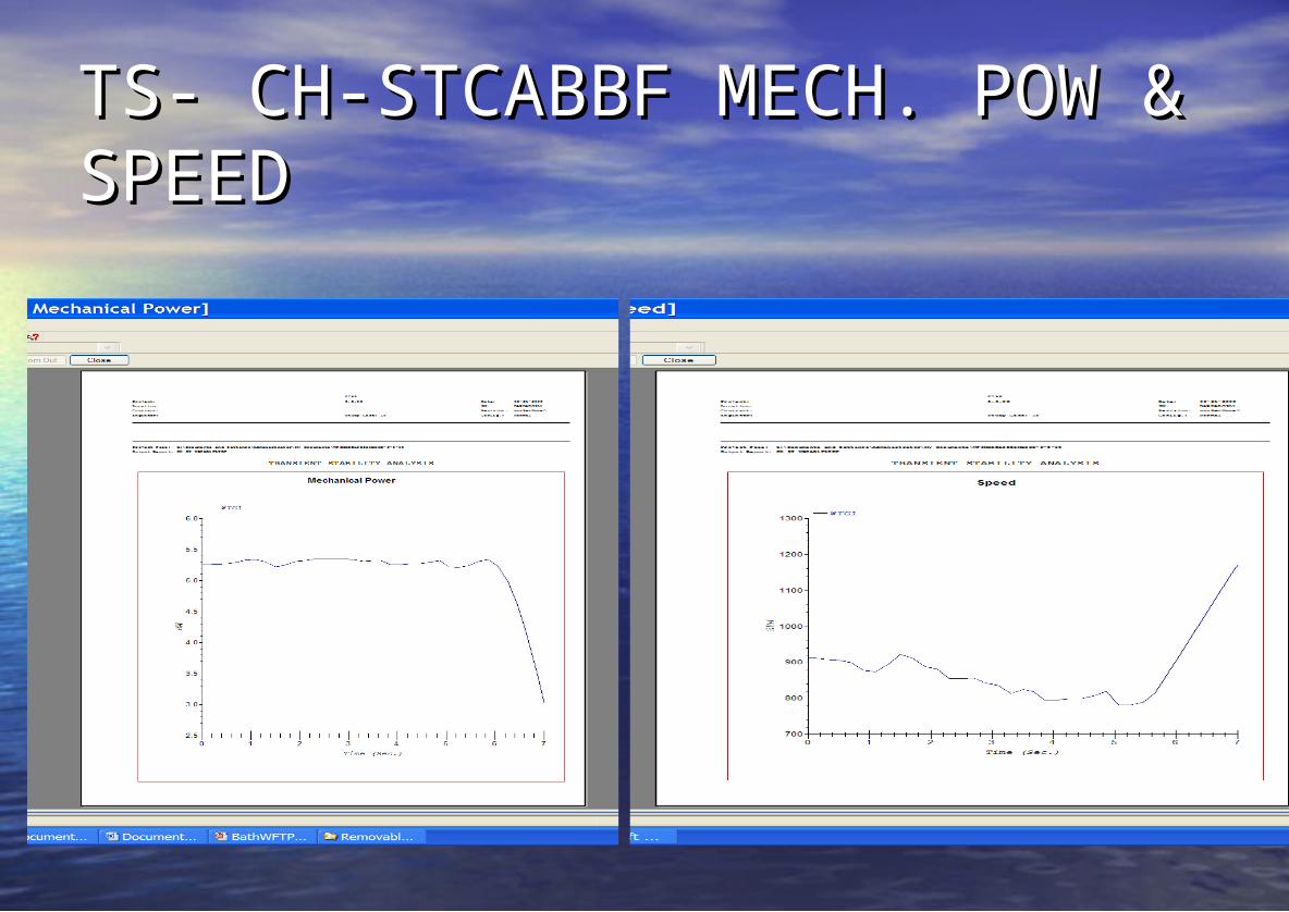
• Analysing TS - the study period is 3-5 Analysing TS - the study period is 3-5 secs. after disturbance. May be secs. after disturbance. May be extended to 10 secs. or more.extended to 10 secs. or more.
PS STUDY CONSIDERATIONSPS STUDY CONSIDERATIONS• LOAD FLOWSLOAD FLOWS• CURRENT FLOWS IN EACH BRANCH CURRENT FLOWS IN EACH BRANCH
OF NETWORKOF NETWORK• REAL & REACTIVE POWER FLOWSREAL & REACTIVE POWER FLOWS• VOLTAGES AT EACH NODEVOLTAGES AT EACH NODE• VOLTAGE BOOST AT CONTROL NODESVOLTAGE BOOST AT CONTROL NODES• LOSSESLOSSES
FAULT LEVEL STUDIESFAULT LEVEL STUDIES
•TOTAL FAULT CURRENT AT TOTAL FAULT CURRENT AT FAULTED NODEFAULTED NODE
•ANGLE OF FAULT CURRENT ANGLE OF FAULT CURRENT RELATIVE TO REFERENCE VOLTAGERELATIVE TO REFERENCE VOLTAGE
•FAULT CURRENT DISTRIBUTIONFAULT CURRENT DISTRIBUTION•(CRITICAL TO PROTECTION)(CRITICAL TO PROTECTION)
LOAD FLOW ANALYSISLOAD FLOW ANALYSIS
MATLAB/POWERSIMMATLAB/POWERSIM
ETAP 5.5.0ETAP 5.5.0
ETAP 5.5.0 FEATURESETAP 5.5.0 FEATURES
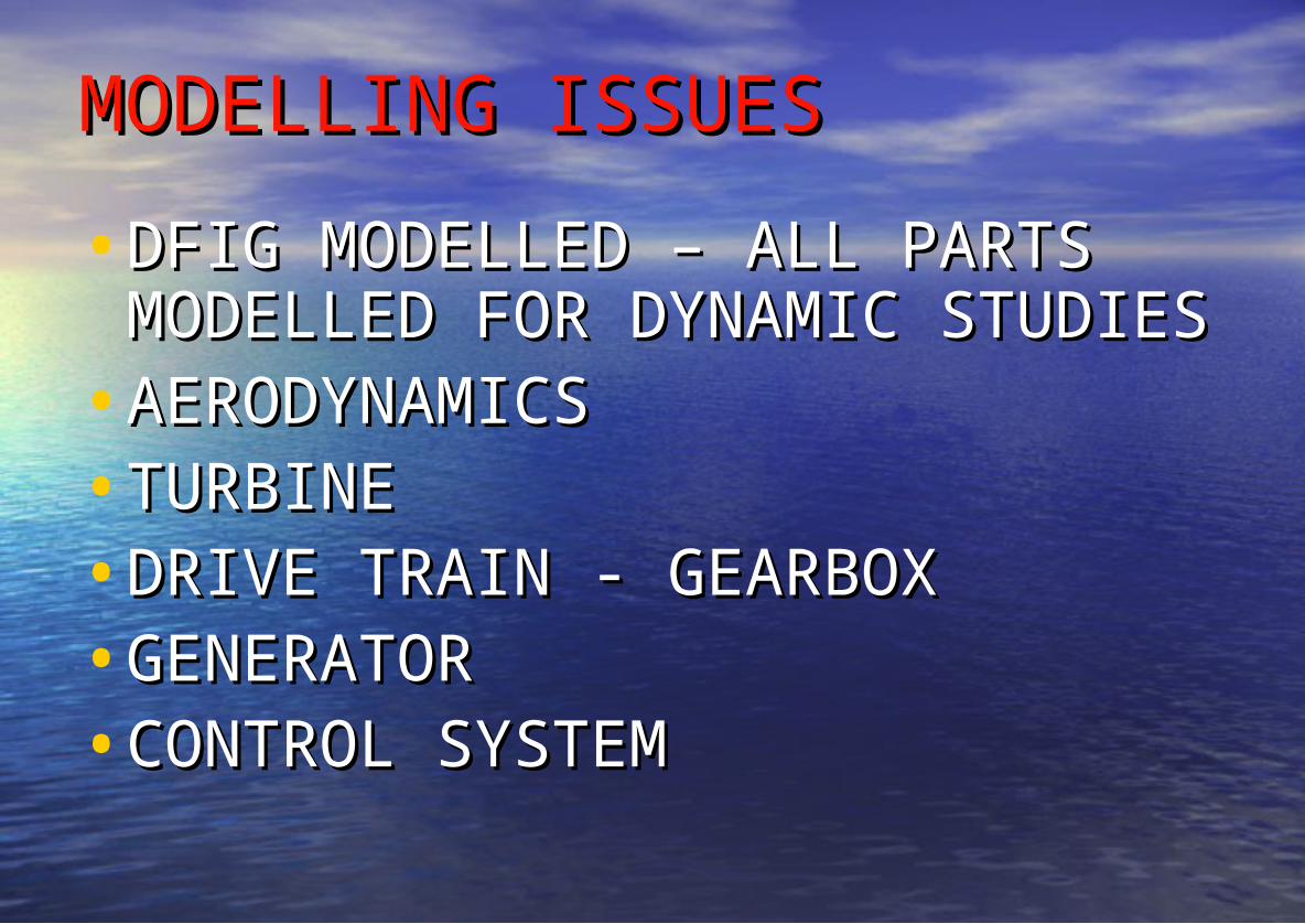
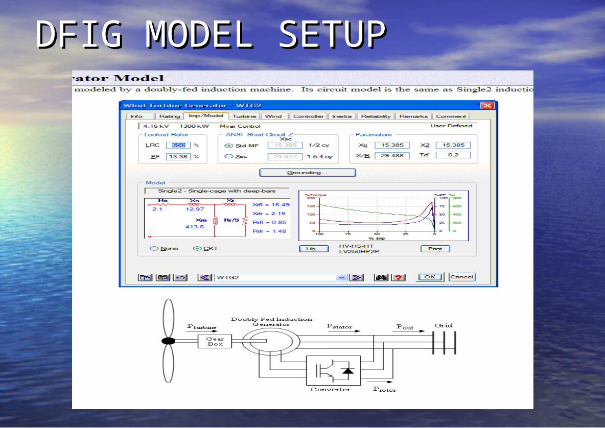
MODELLING ISSUESMODELLING ISSUES•DFIG MODELLED – ALL PARTS DFIG MODELLED – ALL PARTS
MODELLED FOR DYNAMIC MODELLED FOR DYNAMIC STUDIESSTUDIES
•AERODYNAMICSAERODYNAMICS•TURBINETURBINE•DRIVE TRAIN - GEARBOXDRIVE TRAIN - GEARBOX•GENERATORGENERATOR•CONTROL SYSTEMCONTROL SYSTEM
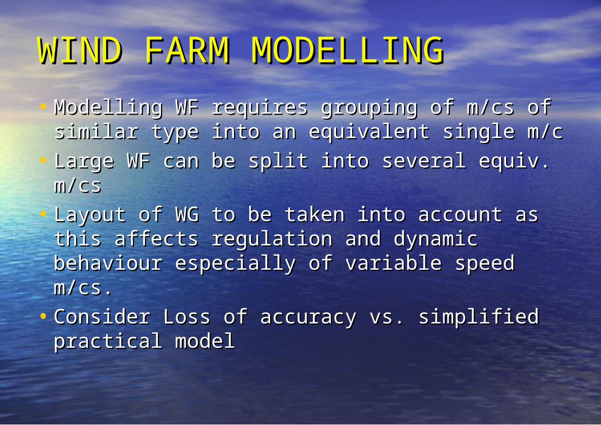
WIND FARM MODELLINGWIND FARM MODELLING• Modelling WF requires grouping of m/cs of Modelling WF requires grouping of m/cs of
similar type into an equivalent single m/csimilar type into an equivalent single m/c• Large WF can be split into several equiv. Large WF can be split into several equiv.
m/csm/cs• Layout of WG to be taken into account as Layout of WG to be taken into account as
this affects regulation and dynamic this affects regulation and dynamic behaviour especially of variable speed m/cs.behaviour especially of variable speed m/cs.
• Consider Loss of accuracy vs. simplified Consider Loss of accuracy vs. simplified practical modelpractical model
EQUAL AREA CRITERION:EQUAL AREA CRITERION:• Divide the machines in the Divide the machines in the
system into two groups: system into two groups: • the critical machines that the critical machines that
are responsible for the loss are responsible for the loss of synchronism, and the of synchronism, and the remaining non critical onesremaining non critical ones
• Replace the two groups by Replace the two groups by two equivalent. machines.two equivalent. machines.
• Replace these machines by Replace these machines by an equivalent single an equivalent single machine, infinite bus machine, infinite bus system.system.
• Evaluate the system stability Evaluate the system stability using the equal area using the equal area criterion.criterion.
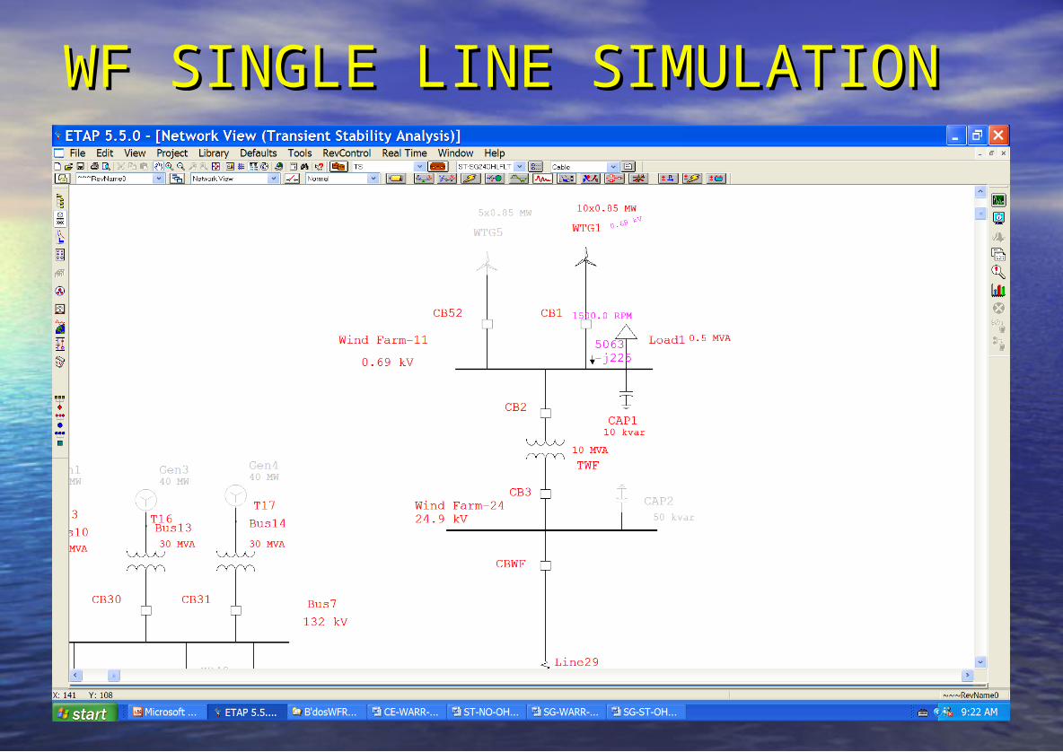
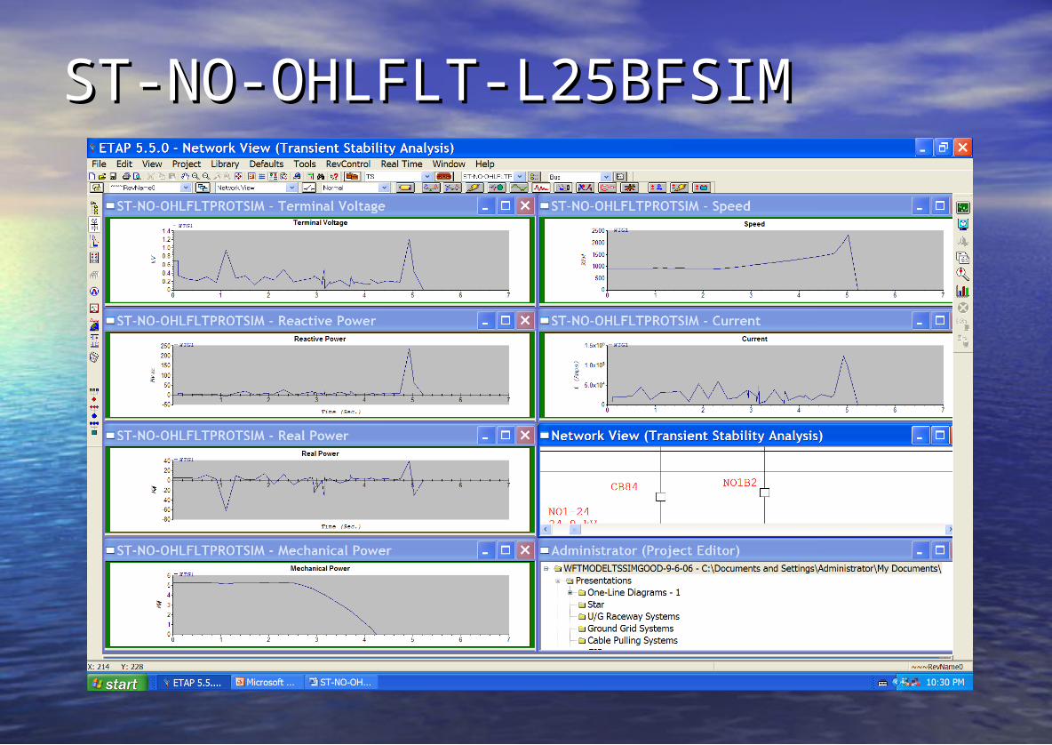
WF SINGLE LINE SIMULATIONWF SINGLE LINE SIMULATION