Role of Synchronized Measurements Role of Synchronized Measurements In Operation of Smart Grids In Operation of Smart Grids Ali Abur Ali Abur Electrical and Computer Engineering Department Electrical and Computer Engineering Department Northeastern University Northeastern University Boston, Massachusetts Boston, Massachusetts Boston University Boston University CISE Seminar CISE Seminar November 12, 2010 November 12, 2010
Transcript
Role of Synchronized MeasurementsRole of Synchronized Measurements In Operation of Smart GridsIn Operation of Smart Grids
Ali AburAli AburElectrical and Computer Engineering DepartmentElectrical and Computer Engineering Department
Boston UniversityBoston UniversityCISE SeminarCISE Seminar
November 12, 2010November 12, 2010
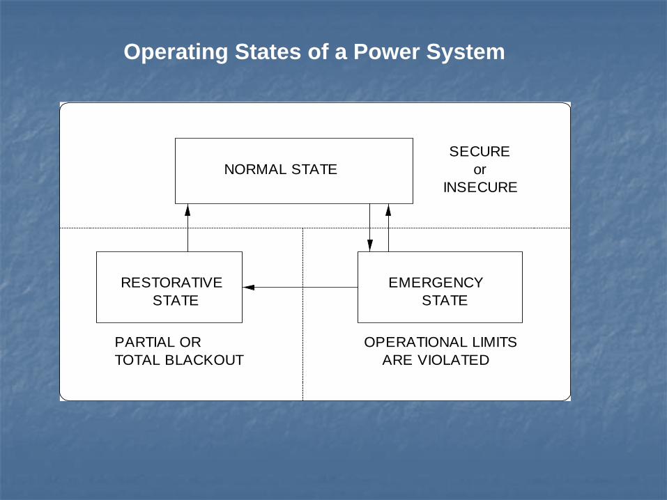
Operating States of a Power System
RESTORATIVE STATE
PARTIAL ORTOTAL BLACKOUT
SECURE or
INSECURE
OPERATIONAL LIMITSARE VIOLATED
EMERGENCY STATE
NORMAL STATE
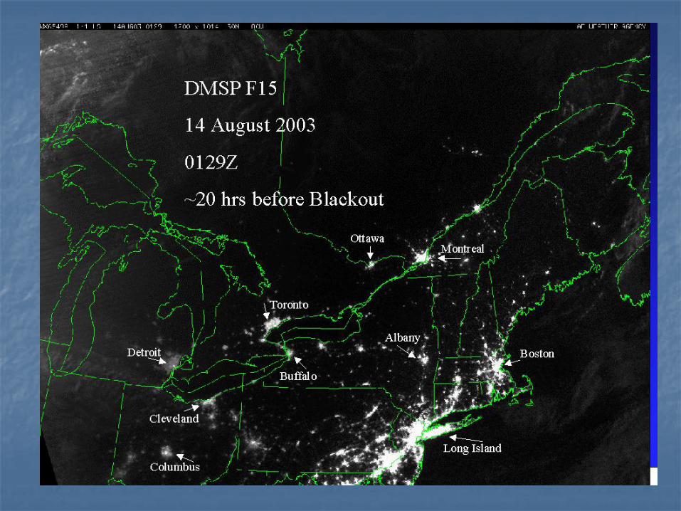
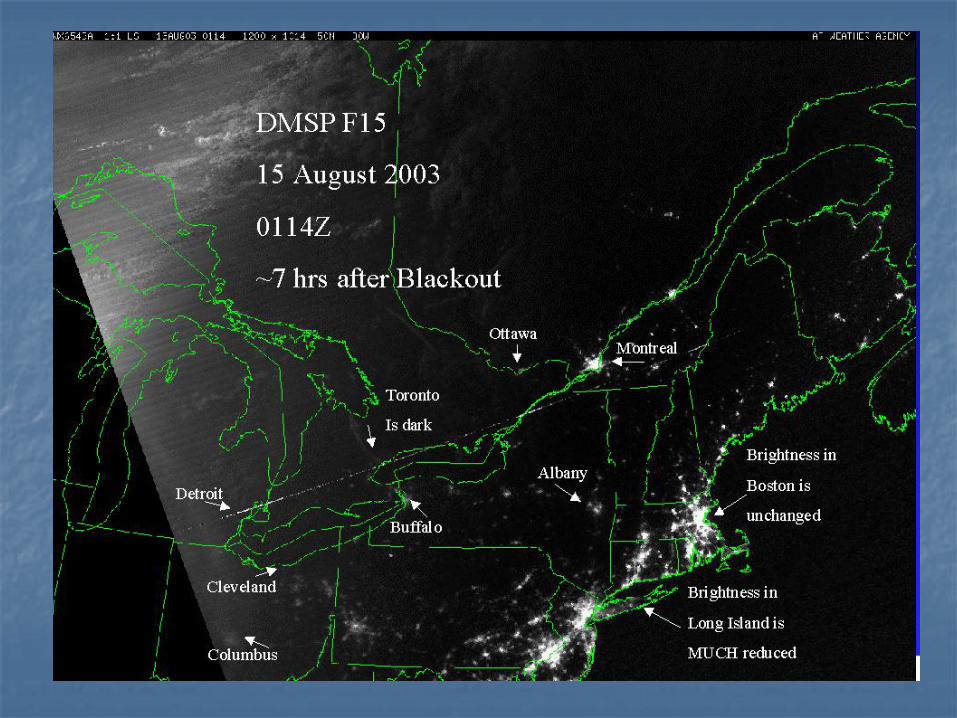
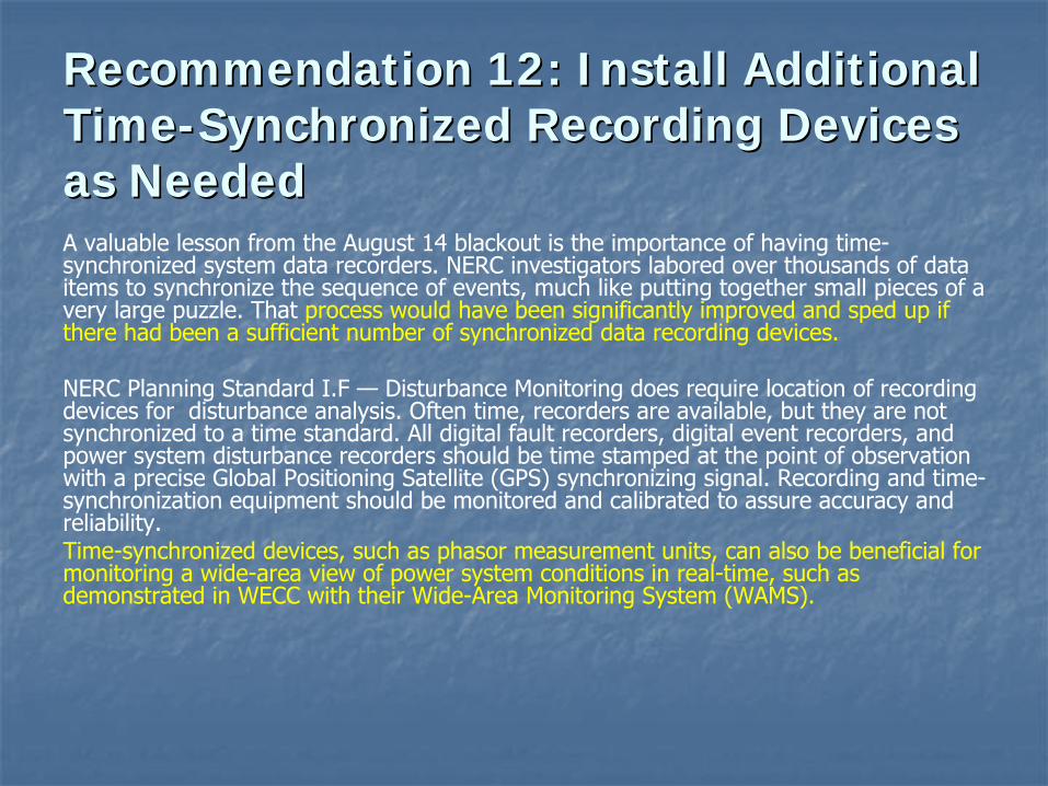
Recommendation 12: Install Additional Recommendation 12: Install Additional TimeTime--Synchronized Recording Devices Synchronized Recording Devices as Neededas NeededA valuable lesson from the August 14 blackout is the importance of having time-
synchronized system data recorders. NERC investigators labored over thousands of data items to synchronize the sequence of events, much like putting together small pieces of a very large puzzle. That process would have been significantly improved and sped up if there had been a sufficient number of synchronized data recording devices.
NERC Planning Standard I.F —
Disturbance Monitoring does require location of recording devices for disturbance analysis. Often time, recorders are available, but they are not synchronized to a time standard. All digital fault recorders, digital event recorders, and power system disturbance recorders should be time stamped at the
point of observation with a precise Global Positioning Satellite (GPS) synchronizing signal. Recording and time-
synchronization equipment should be monitored and calibrated to assure accuracy and reliability.Time-synchronized devices, such as phasor measurement units, can also
be beneficial for monitoring a wide-area view of power system conditions in real-time, such as demonstrated in WECC with their Wide-Area Monitoring System (WAMS).
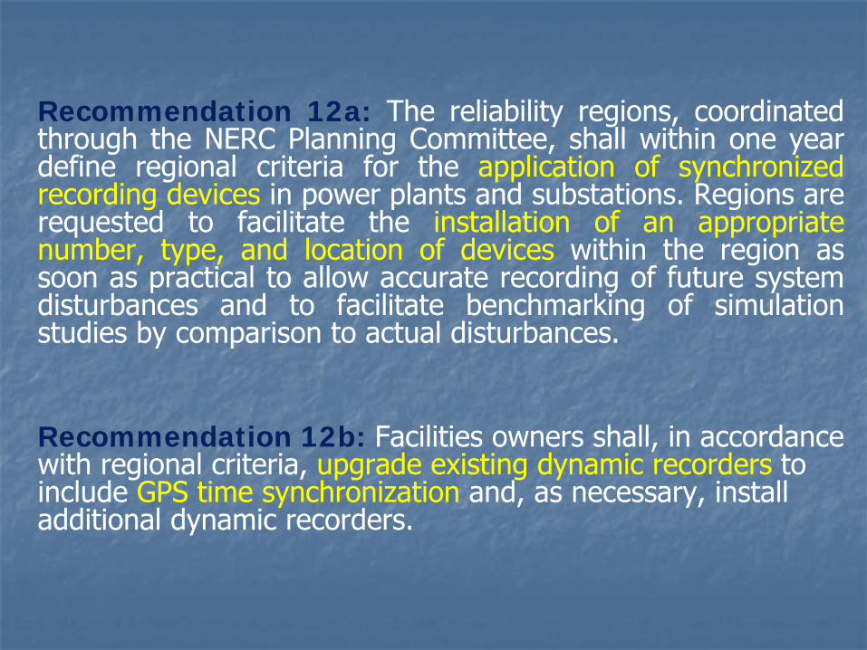
Recommendation 12a: The reliability regions, coordinated through the NERC Planning Committee, shall within one year define regional criteria for the application of synchronized recording devices
in power plants and substations. Regions are
requested to facilitate the installation of an appropriate number, type, and location of devices within the region as soon as practical to allow accurate recording of future system disturbances and to facilitate benchmarking of simulation studies by comparison to actual disturbances.
Recommendation 12b: Facilities owners shall, in accordance with regional criteria, upgrade existing dynamic recorders to include GPS time synchronization and, as necessary, install additional dynamic recorders.
Tenets of Smart Grid Operation(Department of Energy)
Self-healing from power disturbance events
Enabling active participation by consumers in demand response
Operating resiliently against physical and cyber attacks
Providing power quality for 21st century needs
Accommodating all generation and storage options
Enabling new products, services, and markets
Optimizing assets and operating efficiently
Role of State EstimationFacilitating Smart Grid Operation
Self-healing from power disturbance eventsFaster (scan rate) state estimation, wide-area observability, multi-level monitoring capability
Enabling active participation by consumers in demand responseMonitoring at lower voltage levels
Operating resiliently against physical and cyber attackRedundancy and strategic placement of measuring devices/sensorsDetection, identification and elimination of errors in data and models
Providing power quality for 21st century needsAccommodating all generation and storage optionsEnabling new products, services, and marketsWide-area monitoring to facilitate the feedback to address congestion, avoid spilling renewable energy, active market participation
Optimizing assets and operating efficientlyMonitoring dynamic line loading, equipment operating limits
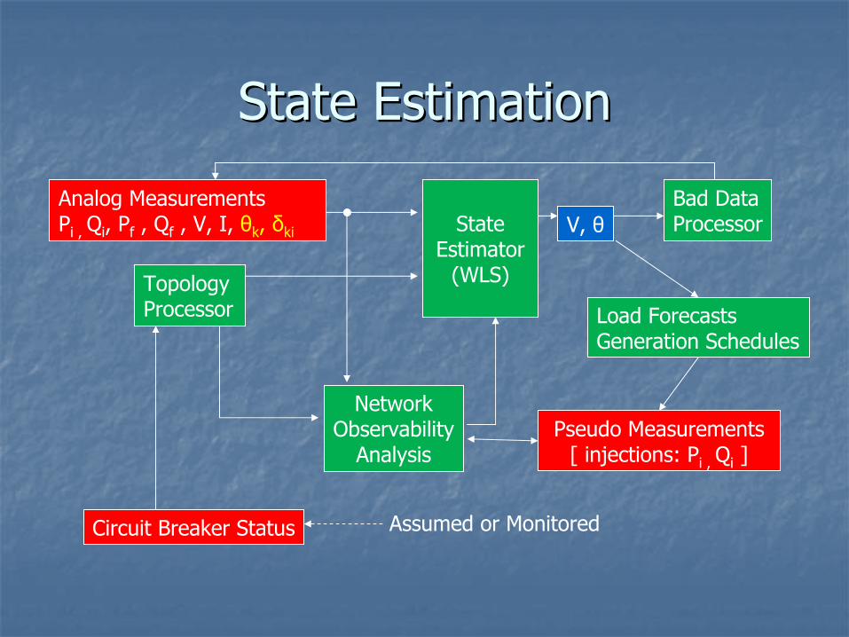
State Estimation State Estimation
Analog MeasurementsPi , Qi
, Pf
, Qf
, V, I, θk
, δki
Circuit Breaker Status
State Estimator
(WLS)
Bad DataProcessor
NetworkObservability
Analysis
Topology Processor
V, θ
Assumed or Monitored
Pseudo Measurements[ injections: Pi , Qi
]
Load ForecastsGeneration Schedules
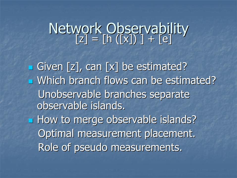
Measurement ModelMeasurement Model
Given a set of measurements, [z]Given a set of measurements, [z]and the correct network topology/parameters:and the correct network topology/parameters:
Given [z], can [x] be estimated?Given [z], can [x] be estimated?
Which branch flows can be estimated?Which branch flows can be estimated?Unobservable branches separate Unobservable branches separate observable islands.observable islands.
How to merge observable islands?How to merge observable islands?Optimal measurement placement.Optimal measurement placement.Role of pseudo measurements.Role of pseudo measurements.
Observable IslandsObservable Islands
ISLAND 1 ISLAND 2
ISLAND 3
Loss of Observability due to Line SwitchingLoss of Observability due to Line Switching
OBSERVABLECLOSED CB
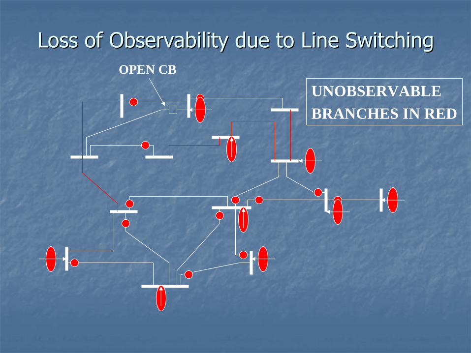
Loss of Observability due to Line SwitchingLoss of Observability due to Line Switching
UNOBSERVABLEBRANCHES IN RED
OPEN CB
Robustness Against Topology ChangesRobustness Against Topology Changes
ObservableObservable
Observable Unobservable
Base Case
Base Case
Meter PlacementGiven a set of measurements
z = h(x) + e
Must be able to estimate x using “z”
if
any one measurement is missing, or
any branch is disconnected
Accomplish the above with least cost metering upgrade
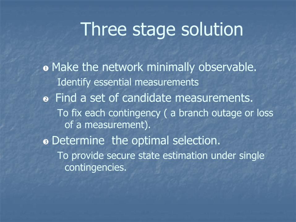
Three stage solution
Make the network minimally observable.Identify essential measurements
Find a set of candidate measurements.To fix each contingency ( a branch outage or loss
of a measurement).
Determine the optimal selection.To provide secure state estimation under single
contingencies.
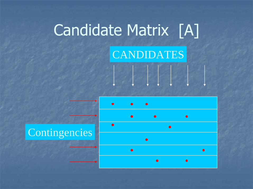
Candidate Matrix [A]CANDIDATES
Contingencies
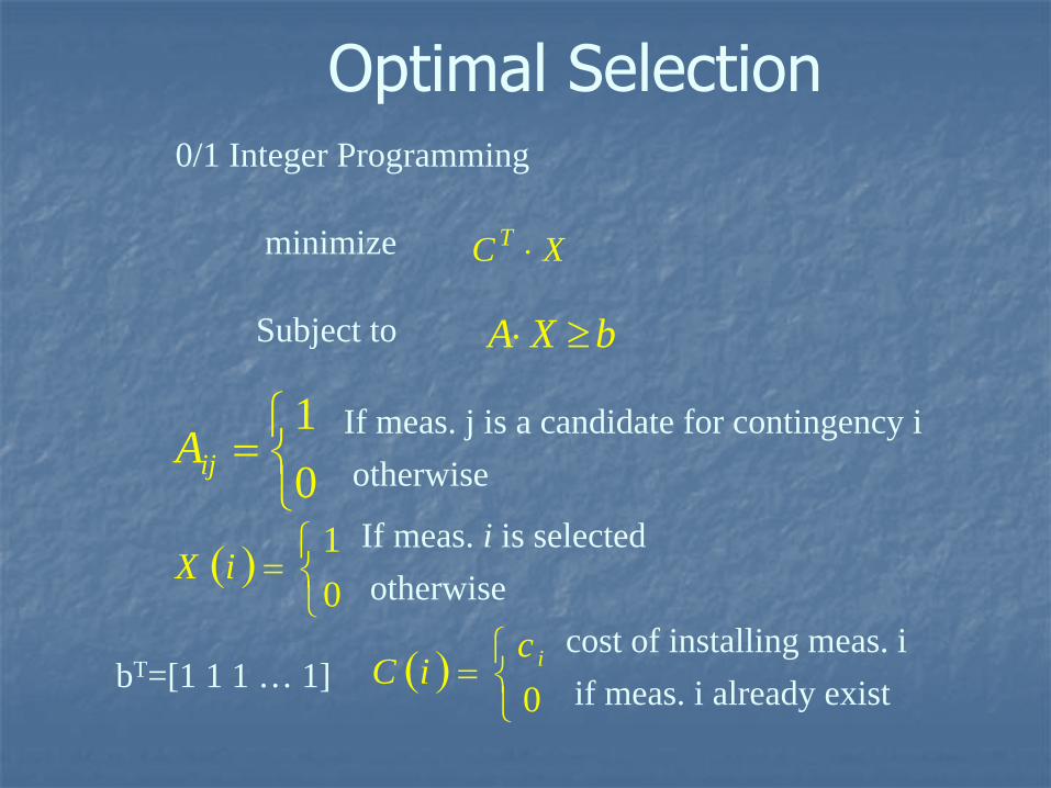
Optimal Selection
XC T minimize
bXA Subject to
0/1 Integer Programming
01
ijA If meas. j is a candidate for contingency iotherwise
01
iXIf meas. i is selectedotherwise
bT=[1 1 1 … 1]
0
iciC
cost of installing meas. iif meas. i already exist
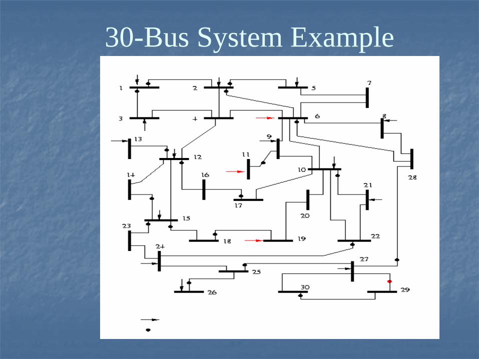
30-Bus System Example
PMU Measurements:PMU Measurements:
Several channels measuring:Several channels measuring:
Phase angles or magnitudes of bus voltagesPhase angles or magnitudes of bus voltages
Phase angles or magnitudes of branch currentsPhase angles or magnitudes of branch currents
Use of synchronization signals from the Use of synchronization signals from the global positioning satellite (GPS) systems global positioning satellite (GPS) systems
Minimal time skew between measurementsMinimal time skew between measurements
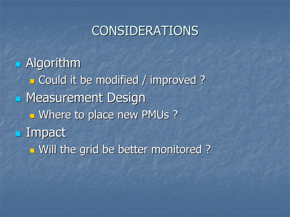
CONSIDERATIONSCONSIDERATIONS
AlgorithmAlgorithm
Could it be modified / improved ? Could it be modified / improved ?
Measurement DesignMeasurement Design
Where to place new PMUs ?Where to place new PMUs ?
Impact Impact
Will the grid be better monitored ?Will the grid be better monitored ?
State Estimation with PMUsState Estimation with PMUsMathematical model Mathematical model
r
xhxh
xhxhxh
zzzzz
I
I
V
trad
I
I
V
trad
)()(
)()()(
)Im(
)Re(
)Im(
)Re(
rxhztoSubjectWrrxJMinimize T
)()(
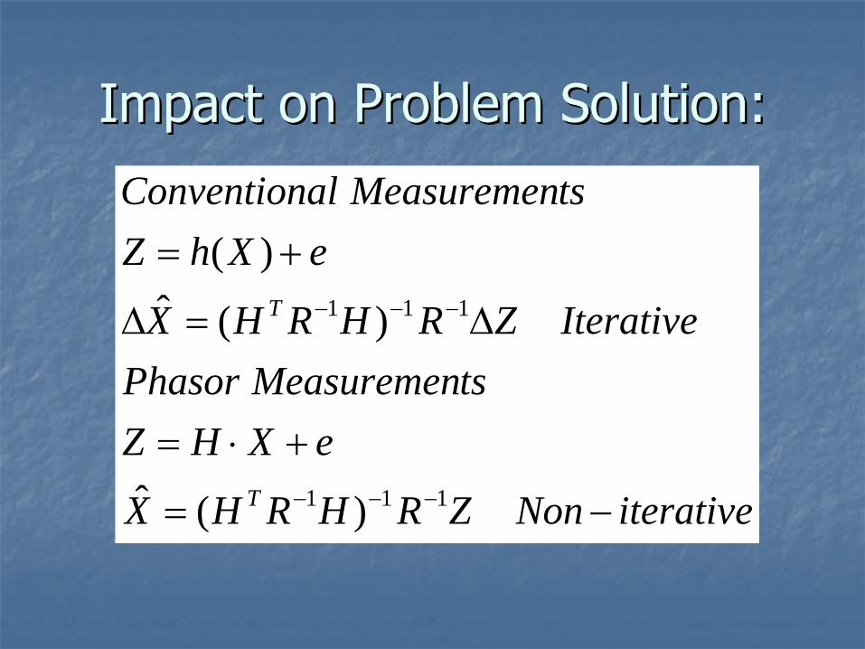
Impact on Problem Solution:Impact on Problem Solution:
iterativeNonZRHRHX
eXHZtsMeasuremenPhasor
IterativeZRHRHX
eXhZtsMeasuremenalConvention
T
T
111
111
)(ˆ
)(ˆ)(
Removal of Slack (Ref) BusRemoval of Slack (Ref) Bus
Eliminate the reference phase angle from Eliminate the reference phase angle from the SE formulation. the SE formulation.
Bad data in conventional as well as PMU Bad data in conventional as well as PMU measurements can be detected and measurements can be detected and identified with sufficiently redundant identified with sufficiently redundant measurement sets. measurement sets.
3 Critical PMUs3 Critical PMUs Error in PMU at Bus 12Error in PMU at Bus 12
MeasurementNormalized
residual
0.01130.01120.00820.00760.0064
Test A
87p8p2q
1V
3q
NO BAD DATADETECTED
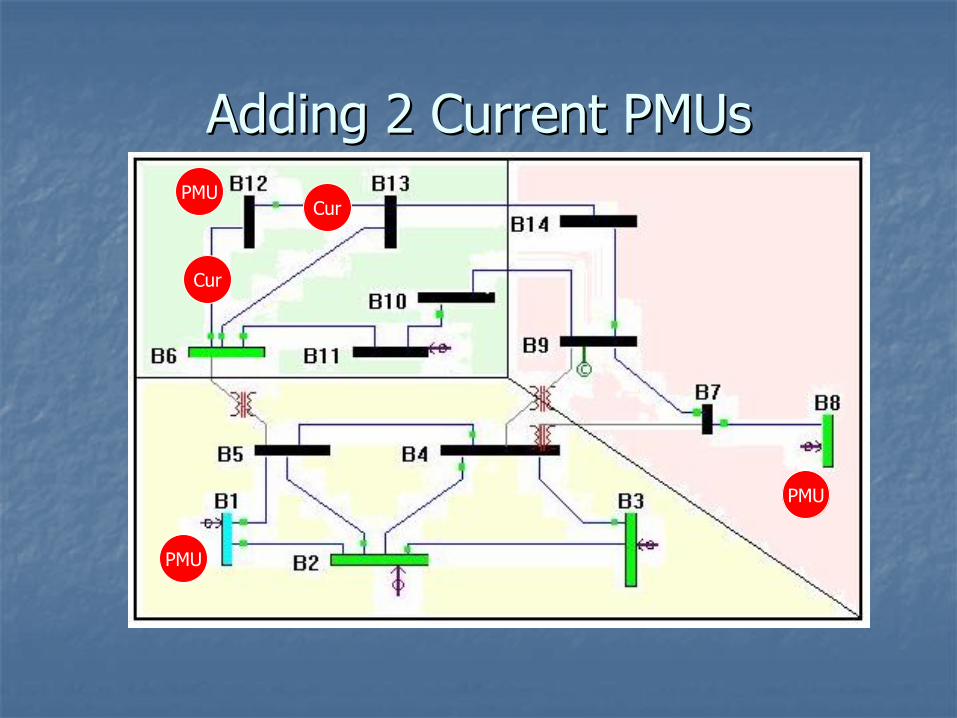
Adding 2 Current PMUsAdding 2 Current PMUs
PMU
PMU
PMU
Cur
Cur
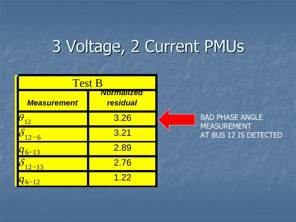
3 Voltage, 2 Current PMUs3 Voltage, 2 Current PMUs
MeasurementNormalized
residual
3.263.212.892.761.22
Test B
12
612
136q1312
126q
BAD PHASE ANGLEMEASUREMENTAT BUS 12 IS DETECTED
A Practical AdvantageA Practical Advantage
PMUs can be placed at any bus in the PMUs can be placed at any bus in the observable island.observable island.
PseudoPseudo--measurements can merge measurements can merge observable islands only if they are incident observable islands only if they are incident to the boundary buses.to the boundary buses.
PMUs with Multiple Channels:PMUs with Multiple Channels:
PMUV phasorV phasor
I phasorsI phasors
PMU with multiple channels will measure:• V_phasor at the bus• I_phasors for all incident branches
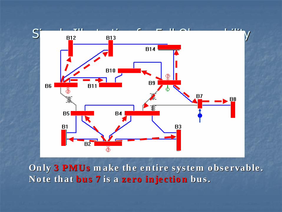
Simple Illustration for Full ObservabilitySimple Illustration for Full Observability
Only Only 3 PMUs3 PMUs make the entire system observable.make the entire system observable.Note that Note that bus 7bus 7 is a is a zero injectionzero injection bus.bus.
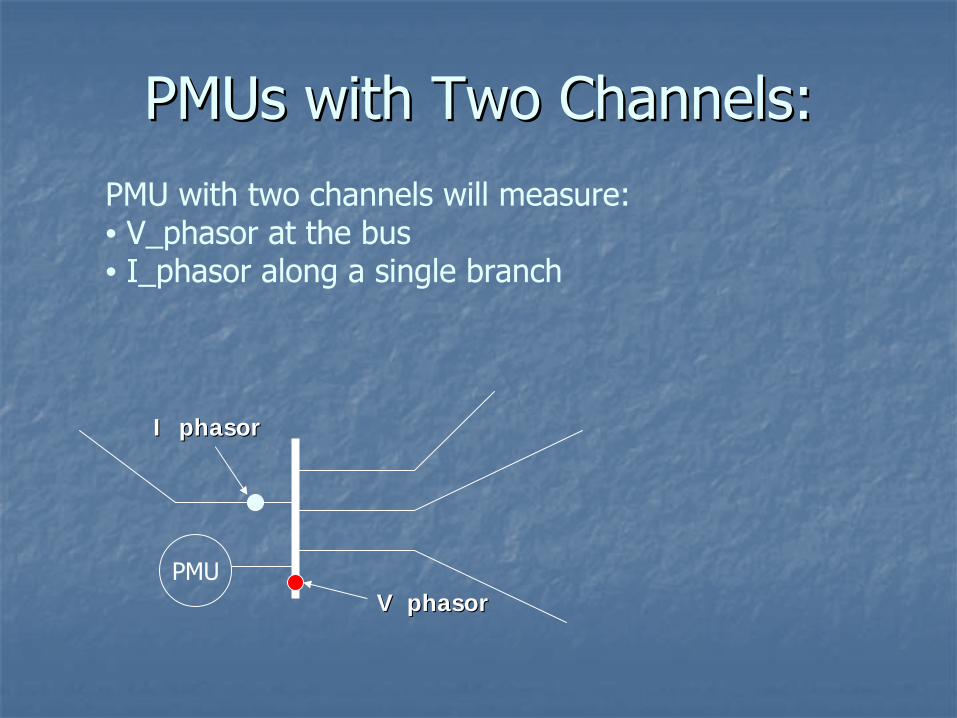
PMUs with Two Channels:PMUs with Two Channels:
PMUV phasorV phasor
I phasorI phasor
PMU with two channels will measure:• V_phasor at the bus• I_phasor along a single branch
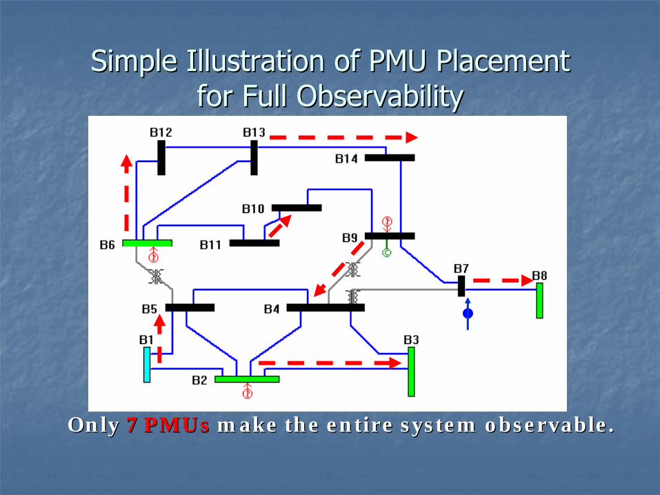
Simple Illustration of PMU PlacementSimple Illustration of PMU Placement for Full Observabilityfor Full Observability
Only Only 7 PMUs7 PMUs make the entire system observable.make the entire system observable.
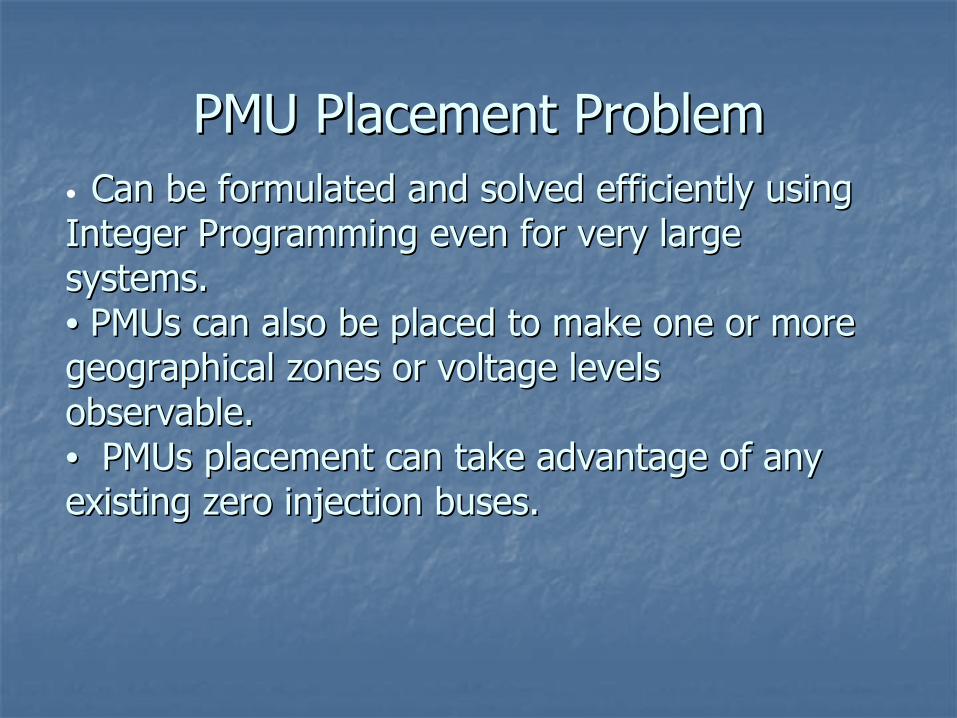
PMU Placement ProblemPMU Placement Problem•
Can be formulated and solved efficiently using Can be formulated and solved efficiently using Integer Programming even for very large Integer Programming even for very large systems.systems.•• PMUs can also be placed to make one or more PMUs can also be placed to make one or more geographical zones or voltage levels geographical zones or voltage levels observable.observable.•• PMUs placement can take advantage of any PMUs placement can take advantage of any existing zero injection buses.existing zero injection buses.
Effects of considering zero injectionsEffects of considering zero injections
Systems No. of zero injections
Number of PMUs
Ignoring zeroInjections
Using zero injections
14-bus 1 4 3
57-bus 15 17 12
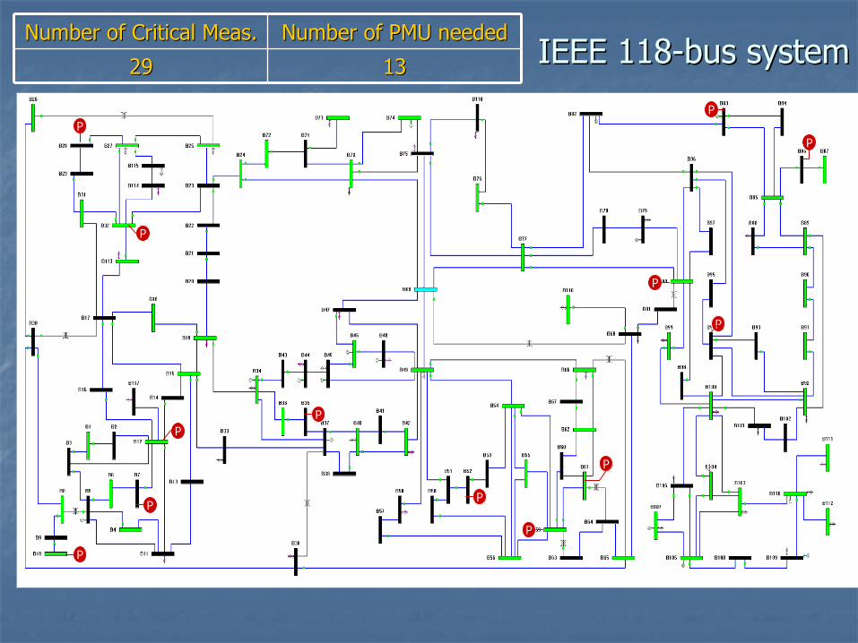
118-bus 10 32 29
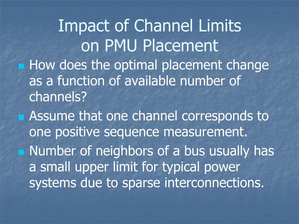
Impact of Channel Limits on PMU Placement
How does the optimal placement change as a function of available number of channels?
Assume that one channel corresponds to one positive sequence measurement.
Number of neighbors of a bus usually has a small upper limit for typical power systems due to sparse interconnections.
6136126116106968677106710571048103911214151
530-bus
445444443552771
114-bus
Consider Zero Injections
Ignore Zero Injections ChannelsZero InjectionsSystem
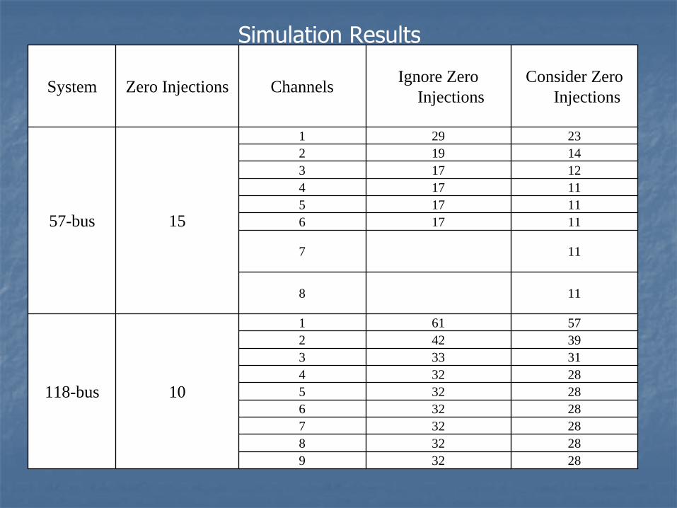
Simulation Results
283292832828327283262832528324313333942257611
10118-bus
118
117
111761117511174121731419223291
1557-bus
Consider Zero Injections
Ignore Zero Injections Channels Zero InjectionsSystem
Simulation Results
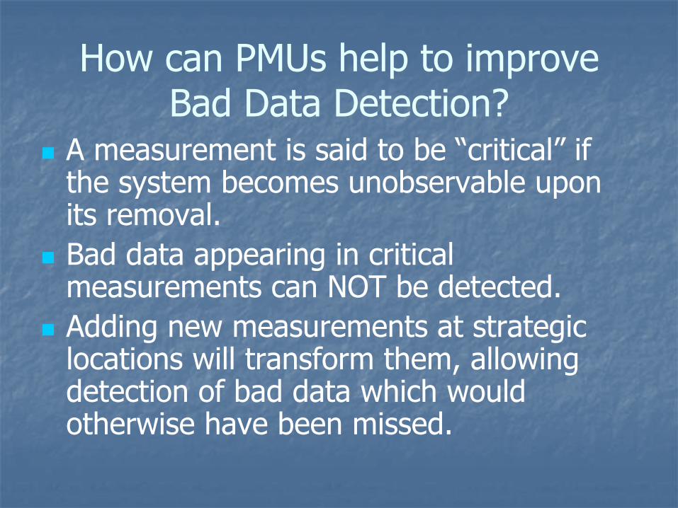
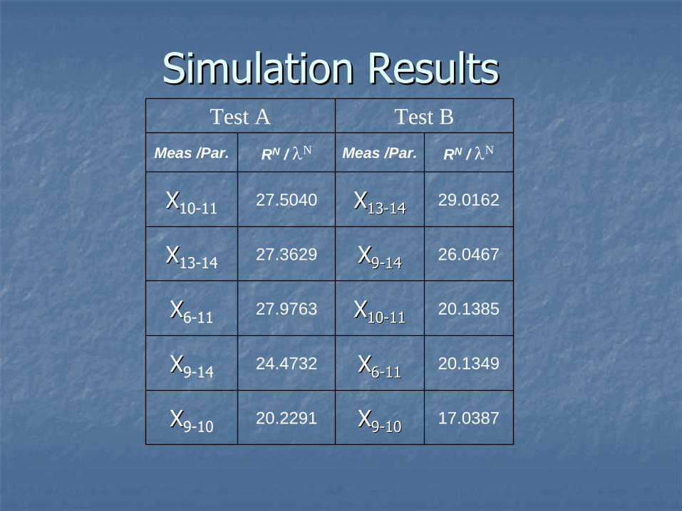
How can PMUs help to improve Bad Data Detection?
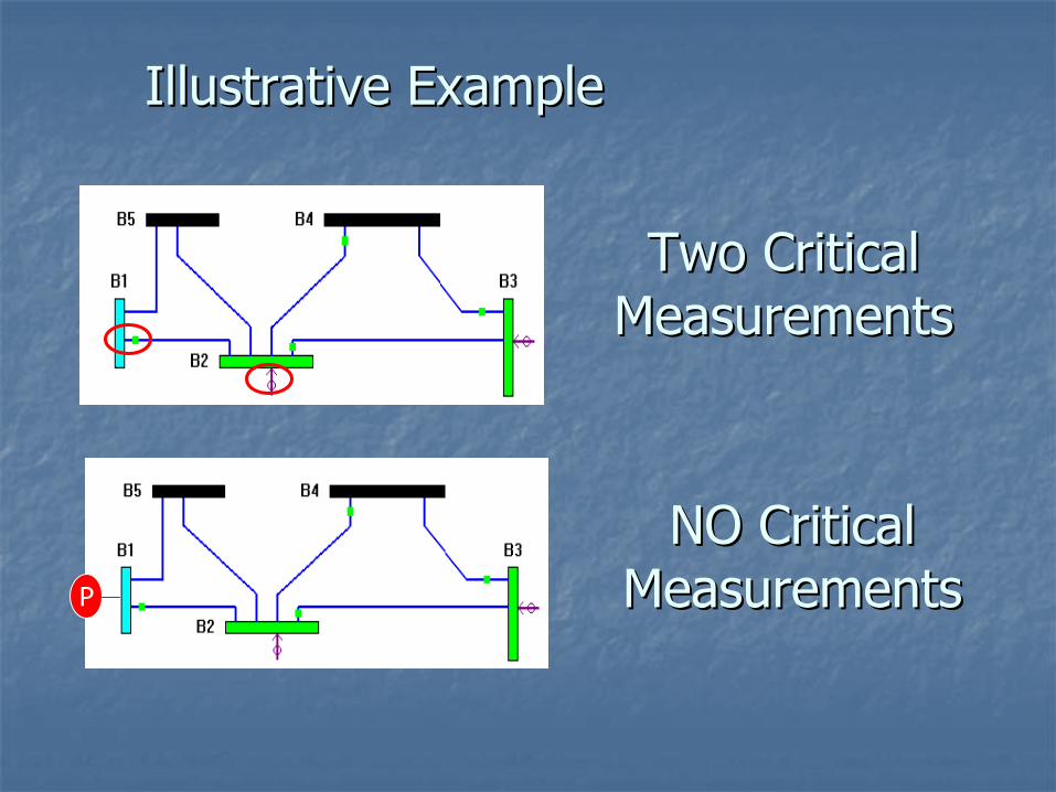
A measurement is said to be “critical”
if the system becomes unobservable upon its removal.
Bad data appearing in critical measurements can NOT be detected.
Adding new measurements at strategic locations will transform them, allowing detection of bad data which would otherwise have been missed.
Illustrative ExampleIllustrative Example
P
Two Critical Two Critical MeasurementsMeasurements
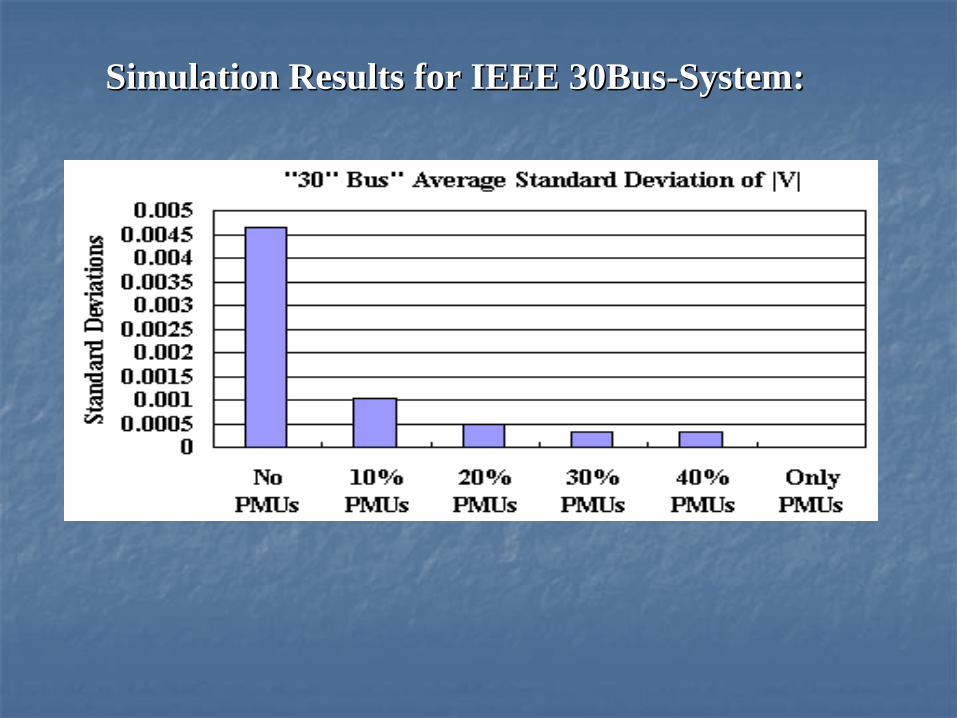
Simulation Results for IEEE 30BusSimulation Results for IEEE 30Bus--System:System:
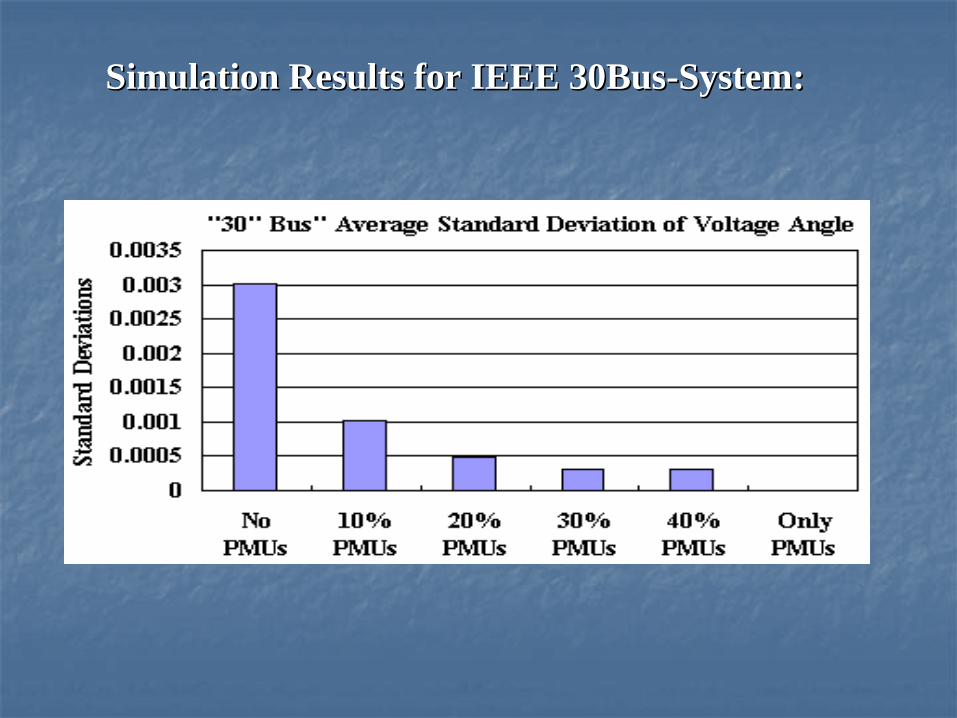
Simulation Results for IEEE 30BusSimulation Results for IEEE 30Bus--System:System:
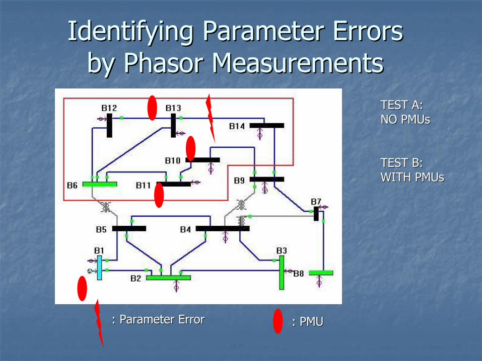
Impact of PMUs onImpact of PMUs on Parameter Error IdentificationParameter Error Identification
When a network parameter is wrong:When a network parameter is wrong:
Can it be identified ? How ?Can it be identified ? How ?
Are there cases where errors in certain Are there cases where errors in certain parameters can not be identified without parameters can not be identified without synchronized phasor measurements ?synchronized phasor measurements ?
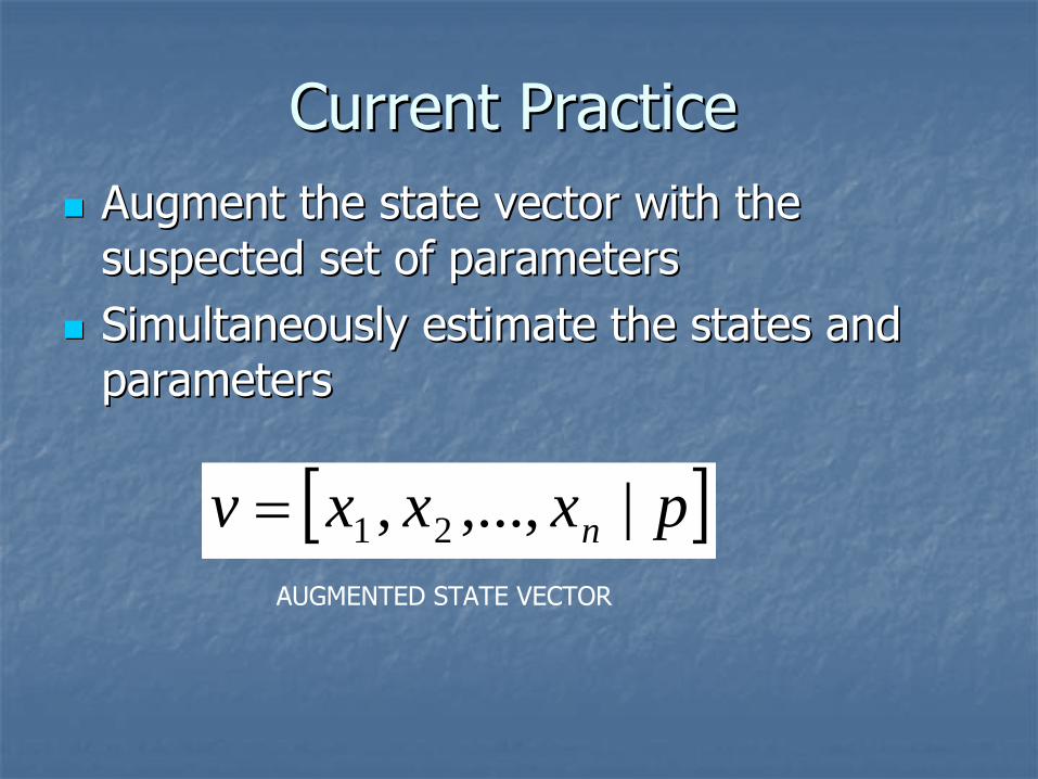
Current PracticeCurrent Practice
Augment the state vector with the Augment the state vector with the suspected set of parameterssuspected set of parameters
Simultaneously estimate the states and Simultaneously estimate the states and parameters parameters
pxxxv n |,...,, 21AUGMENTED STATE VECTOR
Multiple SolutionsMultiple Solutions
What happens when more than one set of What happens when more than one set of parameters satisfies all measurements?parameters satisfies all measurements?
Multiplicity of solutions for [p].Multiplicity of solutions for [p].
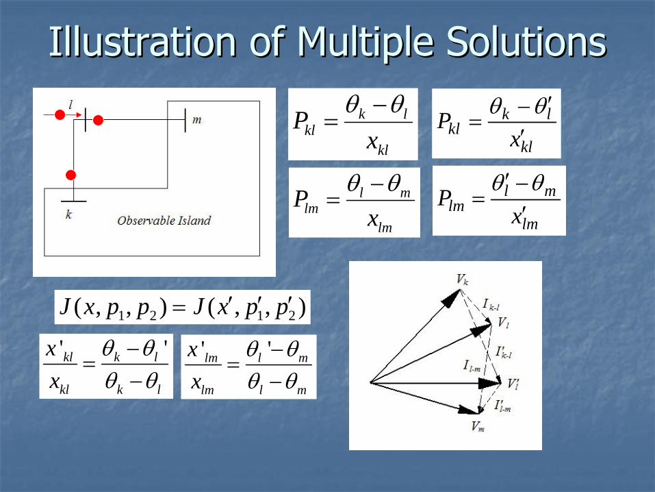
Illustration of Multiple SolutionsIllustration of Multiple Solutions
SE performance have significant impact on SE performance have significant impact on all other application functions related to all other application functions related to smart grid operationsmart grid operation
PMUs can improve SE performance in the PMUs can improve SE performance in the following areas:following areas:
Bad data detectionBad data detection
Reduced variance of estimated stateReduced variance of estimated state