24
ROLL UP DIVIDER CURTAIN No. 675 Installation, Operation, and Maintenance Manual © 2012 PORTER ATHLETIC, INC. ALL RIGHTS RESERVED INST00122125 07-23-2012

1
ROLL UP DIVIDER CURTAIN No. 675
Installation, Operation, and Maintenance Manual
© 2012 PORTER ATHLETIC, INC. ALL RIGHTS RESERVED
INST00122125 07-23-2012

2
INSTRUCTIONS: Dealer and/or Installation Supervisor, Please give this book to the Owner/Customer
GUARANTEE
All materials and workmanship of basic materials are guaranteed to be free and clear of defects. Defective material will be repaired or replaced, at our option, subsequent to complete information being received by us concerning the nature of the defect for a period of one year from the date established by the certificate of occupancy or certificate of substantial completion, whichever shall occur first or otherwise documented and signed by an officer of Porter Athletic, Inc.
NAME OF PROJECT:
NAME OF DEALER: NAME OF INSTALLATION COMPANY:
PHONE #: PHONE #:
Porter Order Number _________________________
Date of Scheduled Shipment _________________________
Date of Substantial Completion _________________________
The gymnasium equipment for this project has been custom fabricated according to the Owner’s/Architect’s specification. Care has been taken to fabricate and install this equipment to provide years of safe, satisfactory use and trouble free service. The key to satisfactory service is proper operation and care. Should any malfunctions occur, please notify your supervisor and call your local Porter Dealer or Representative.

3
LIABILITY
Liability is not only an issue with the installation and maintenance of this product, but it also extends to the proper operation by the end user. The operational instructions must be read and understood before operating this equipment! This manual for the model No. 675 Roll-Up® Divider Curtains, which provides explicit examples of a variation of overhead attachments, is meant to serve as a general guideline only, for the safe installation of this product. Variables must be taken into consideration which are outside of Porter's control, including, but not limited to, steel joist variations which include splice plate interference, web panel point attachments if specified by the architect, conduit interference, HVAC and sprinkler interference, non-grouted cells of block walls, spacing and frequency of wall ties, appropriate selection of wall anchors for the given wall composition, proper installation of said anchors, embed depth of the anchors, etc. It is Porter's explicit requirement that this product be installed in a safe and secure manner. Any structural deviation from Porter installation drawings without written authorization will void all warranties. Contact the factory immediately should such a condition exist, necessitating a design revision. All anchor and fastening methodology is to comply with the International Conference of Building Officials (ICBO), the Uniform Building Code (UBC), the Industrial Fastener Institute (IFI), and all state regulatory agencies, such as The Division of the State Architect (DSA) in California. General Hardware Guidelines • Do not substitute hardware without written authorization from the factory. • Minimum Grade 5 hardware is to be utilized at all attachments, unless specified otherwise. Refer to the
specific part drawing in this manual for the proper grade of hardware.
• On eyebolt applications, a turned eye is not acceptable. Utilize forged eyebolts or, if necessary, a turned eye that is welded closed.
• Do not substitute for the factory-supplied cable and cable clamps. The quality of the 1/8" cable and
clamps can vary widely from different manufacturers, and are not all suited for curtain applications. • All “S” hook connections must be crimped closed. • All Nicopress® clamps must be installed utilizing the proper tool and technique listed in this manual,
ensuring a “worn” tool is NOT used. Nicopress® clamps must be copper. Never use aluminum clamps.

4
TABLE OF CONTENTS
MANUAL OVERVIEW ............................................................................... 5 OPERATIONAL INSTRUCTIONS ............................................................. 6 MAINTENANCE CHECKLIST ................................................................ 7-8 INSPECTION CHECKLIST ........................................................................ 9 INVENTORY AND TOOLS ...................................................................... 10 INSTALLATION INSTRUCTIONS ...................................................... 11-22

5
MODEL No. 675 ROLL-UP® DIVIDER CURTAIN OVERVIEW OF MANUAL
This manual has been prepared to assist you with the installation, operation and maintenance of the No. 675 Roll-Up® Divider Curtain. Enclosed in this manual is an inspection list for your equipment, including operational information. We recommend that you read this manual to become familiar with the operation of the No. 675 Roll-Up® Divider Curtains, and then assign it to the person responsible for the maintenance and inspection program. If you need additional copies of this manual, please let us know. The safest equipment can be damaged when used by the untrained. We suggest that qualified personnel supervise all utilized equipment. For ease of administering this maintenance program, we suggest that your equipment be numbered, and a file maintained on its location, name of manufacturer, original item number, date of purchase, and maintenance performed. This will be useful when ordering replacement parts and keeping track of maintenance. Defective equipment must be marked "DO NOT USE", and the circuit breaker must be turned off and also tagged "DO NOT USE", until replacement or repairs are completed. Inspections should be performed periodically, depending upon the nature of the equipment and its use. When the equipment is exposed to heavy use, special inspections should be made in addition to the normal maintenance program. At the minimum, a yearly inspection of the system is recommended. Any structural and/or electrical deviation from the Porter installation manuals and drawings, without written authorization, will void all warranties.
WARNINGREAD ALL INSTRUCTIONS THOROUGHLY BEFORE ATTEMPTING TO OPERATE THIS EQUIPMENT. FAILURE TO COMPLY WITH THE FOLLOWING INSTRUCTIONS AND WARNINGS MAY RESULT IN SERIOUS INJURIES AND/OR PROPERTY DAMAGE.

6
MODEL NO. 675 ROLL– UP® DIVIDER CURTAIN OPERATIONAL INSTRUCTIONS
The 675 Divider Curtain is powered by an electric winch, which develops tremendous forces. This equipment is to be operated only by qualified personnel to avoid structural damage or possible injury to the operator and other individuals in the gymnasium. Caution should be exerted at all times for safety reasons, keeping the following guidelines in mind: • ONLY authorized, TRAINED personnel are to operate the 675 Divider Curtain. Authorized
personnel is defined as an individual (or individuals) who is at least 21 years of age, has witnessed the proper operation of the unit, and is sanctioned by the facility as being responsible for the operation of the divider curtain.
• The key switch or Powr-Touch® pad, which controls the divider curtain, must be flush mounted
on the wall, located in full view of the operator, and not directly beneath the equipment. • Always make sure the area below the divider curtain and in the path of travel is clear of all
individuals when raising and lowering the unit. • The divider curtain may be raised or lowered by placing the “UP” OR “DOWN” key into the key
switch, and turning as indicated on the switch cover plate. Refer to the separate Powr-Touch® manual for the key pad type operation.
• The key that operates the unit should be retained at all times by a designated authorized person,
or kept in a lock box. Make sure that the key is never left in the key switch unattended! • It is critical the operator visually monitor the area around the curtain through the entire raising
and lowering travel cycles, making certain no one is at or near the curtain travel. Pay particular attention to the unit as it nears a limit switch cut-off juncture. If the limits are not stopping the curtain at the “DOWN” position with minimal cable slack, or allowing the curtain to raise higher than the top of the curtain fabric, contact your Porter representative immediately.
Again the safest equipment can be damaged when used by the untrained. It is imperative the procedures set forth in this manual are strictly observed. Note: The key switch must be labeled with the following operational instructions, as shown. If your key switch is not labeled properly, contact your Porter dealer immediately.
WARNING
ENTRAPMENT OR EQUIPMENT FAILURE.

7
MODEL NO. 675 MAINTENANCE CHECK LIST
The 675 Divider Curtain is designed to operate for many years without any significant service performed. Depending upon the usage of the unit, it is recommended that at least an annual inspection be made, at which time the following steps should be taken: 1. GENERAL
Before inspecting, be certain to follow all OSHA guidelines concerning the use of scaffolds and lifts. The proximity of the scaffold or lift to the curtain must be of adequate distance to provide working clearance, so as not to have the curtain contact the lift during operational checks.
Make certain the Porter key switch or Powr-Touch® pad are not substituted and is located within full view (but not beneath) the divider curtain. Check the walls in close proximity to the curtain for any type of protrusion that may interfere with the raising or lowering of the unit (i.e., new scoreboard, chinning bars, etc.).
2. ELECTRIC WINCH
Although virtually maintenance-free, the electric winch should also be periodically inspected for proper operation of the limit switch assembly and key switch. Refer to the key switch/limit switch section of this manual for adjustment procedure. Inspect the three (3) 1/2” “U”-bolt connections of the frame weldment support to the support tube, ensuring all hardware is tight. The hardware at the building connection is also to be inspected for tightness. The variable ratio drums are to be visually inspected, making certain the incoming cables are aligned with the take-up drums. Cable alignment is critical, and can be easily adjusted by moving the idler pulleys at each cable take-up line across the curtain.
3. LINE SHAFT
Inspect the line shaft for proper rotation on the two (2) roller bearing wheels at each roller bracket location. If the line shaft is not seated symmetrically on the two roller bearings, adjust the turnbuckles accordingly. Inspect the entire line shaft length for concentricity during rotation. If any part of the line shaft rotates with a cam effect (wobble), replace that length of line shaft. Make certain the cause of deflected shaft is identified and remedied, such as a roller support assembly being greater then 3’-0” from a cable drum. Inspect all hardware at line shaft splices and the winch output shafts, tightening as necessary.

8
4. LINE SHAFT SUPPORTS
All support fittings, shaft and pipe splices, support rods, etc. should be inspected for fatigue cracks, loose bolts or set screws, and corrosion, on an annual basis. Replace defective parts as required.
5. ROLLER BRACKET SUPPORTS AND TOP CURTAIN CONNECTIONS
Inspect all turnbuckles and “S” hook connections, making certain the hardware is all “closed”. Alignment of the roller assembly is to be inspected for a smooth rotation of the line shaft.
6. HOISTING BELTS
Inspect all 5” wide hoisting belts for fraying or tears, replacing as necessary. Make sure that all strap plates are secured tightly to line shaft as well as the top curtain support.
7. TOP AND BOTTOM CURTAIN POCKET CONCEALED PIPES
Inspect both the top and bottom pockets, ensuring the concealed pipe is not separating. At the bottom hem, the pipe is to be secured to the fabric at each cable line with a 5/16” bolt through the curtain, the bottom pipe, and secured with a cap nut (see Figure O).
8. FABRIC
Inspect the curtain for any tears or holes in the fabric. Additional fabric is supplied with the curtain, to be used for patching. Industrial vinyl cement will easily bond the vinyl patch to the curtain. Also, check the fabric for signs of tearing or loosening at the seams. Check grommets at all pull‑up lines. The fabric may be cleaned with a mild solution of soap cleaner and water, or Power Foam sold by Rigmar Industries of Elk Grove Village, Illinois (1-800-323-0779).
9. ALUMINUM MOLDING STRIP
Inspect aluminum molding strip and pop rivets, ensuring strips are not pulling up from the 4 1/2” O.D. batten tube. Drill out and replace any loose rivets.
10. CONTRACT MAINTENANCE ALTERNATE
In many facilities, it is possible that the maintenance personnel either do not have the ability or the scaffold to work at the heights required to perform the inspection and maintenance program outlined in this manual. Should your maintenance program be so limited that this program cannot be properly performed, it is highly recommended that a contract‑type inspection/maintenance

9
675 CURTAIN INSPECTION CHECKLIST
Please refer to page 7-8 for details on inspections. This checklist is to assist you in your inspection program. As you are making the inspection, enter “S” for satisfactory, or “R” for repair and replace.
INSPECT ALL ITEMS FOR EACH CURTAIN
ELECTRIC WINCHES #1 #2 #3 #4 #5 #6
LINE SHAFT #1 #2 #3 #4 #5 #6
LINE SHAFT SUPPORTS #1 #2 #3 #4 #5 #6
ROLLER BRACKET SUPPORTS AND TOP CURTAIN CONNECTIONS #1 #2 #3 #4 #5 #6
HOISTING BELTS #1 #2 #3 #4 #5 #6
CABLE DRUMS #1 #2 #3 #4 #5 #6
TOP AND BOTTOM CURTAIN POCKET CONCEALED PIPES #1 #2 #3 #4 #5 #6
FABRIC #1 #2 #3 #4 #5 #6

10
INVENTORY AND INSPECTION
Inventory parts listed on the packing list to ensure parts required are accounted for. Inspect all components for possible shipping damage. Report any shortages to Porter’s Customer Service Department immediately. On visible freight damage, sign as damaged, and file a freight damage claim with the carrier immediately. Failure to report shortages or hidden freight damage directly to Porter’s Customer Service Department within three working days will place the financial burden for the missing or replacement parts with the installer or general contractor.
PREPARATION OF ASSEMBLY AREA
Moving the curtain after assembly is both difficult and awkward. For that reason, the assembly of the curtain should take place below or near the curtain overhead support location. The floor should be protected with a suitable material, covering the entire length of the curtain in the assembly area to prevent damage to the floor or curtain. In addition, the floor and the covering must be free of any debris generated from assembly procedures prior to fabric installation.
TOOLS / EQUIPMENT REQUIRED
To Be Provided by the Installer: • Scaffold or Lift • Hand tools, electric drill, drop cord, vise grip pliers, etc. • Bolt Cutter • Cable Cutter • Measuring tape, Laser Measuring Device • Level, Plumb Bob, Laser Plumb • Nico-Press Crimper “VM” Size • Electronic Test Box (02080-PWR) • “U” Type 1/8” Cable Clamps • Nico-Press Checking Gauge — ”Oval M” Size • Ropes & Pulleys

11
ORIENT CURTAIN ROLLING ACTION ON THE SAME SIDE AS THE KEY
SWITCH MOUNTING LOCATION. THE OPEN FACE OF THE CURTAIN
ROLLING BATTEN MUST BE IN FULL VIEW OF THE OPERATOR. IF THE
KEY SWITCH IS NOT INSTALLED, ASK THE GENERAL CONTRACTOR FOR
THE PROPOSED INSTALLATION LOCATION OF THE KEY SWITCH, AND
MAKE THEM AWARE OF THIS CAUTION.
FINISHED FLOOR
BATTEN TUBE
(SEE DETAIL)
BATTEN TUBE ROTATION DETAIL
ROLLING
BATTEN TUBE
"UP"
ROTATION
PULL-UP
BELT
KEY SWITCH LOCATION
THIS SIDE OF CURTAIN
TO
BE
LT
TIE
-OF
F
TO
LIN
E S
HA
FT
KEY SWITCH
LOCATION
OPEN
FACE
CURTAIN
BELT
TIE-OFF
Detail "A"
THE ROLLING ACTION OF THIS DIVIDER CURTAIN MUST BE FACING THE
LOCATION OF THE KEY SWITCH (OR OTHER OPERATING DEVICE) IN
ORDER THAT THE INDIVIDUAL OPERATING THE SYSTEM WILL BE
VISUALLY AWARE OF ANY INDIVIDUAL OR EQUIPMENT ENTRAPMENT IN
THE ROLLING ACTION OF THE BOTTOM BATTEN TUBE.
CAUTION
ROLLER SUPPORT
CURTAIN FABRIC
PULL-UP BELT
INSTALLATION OF WINCH AND LINE SHAFT 1. Unpack and check all parts and verify quantities with packing list. Verify the location of the curtain with the
architectural prints. (If the winch location needs to be relocated from the installation prints, the line shaft lengths may not work. Contact the factory immediately for additional splices or line shaft lengths.) If the curtain is to be located on a court centerline, be sure to consult with the architect's "court striping plan." Notify the owner, project superintendent or architect if conflicting situations arise. Do not proceed with installation until all conditions are clarified and confirmed. Failure to do so may result in relocating the curtain at the installer’s expense! This step is critical!
2. Locate centerline of curtain on gymnasium floor. Study curtain installation drawings and all details of roller
bracket assemblies, belt assemblies and winch mounting assembly before proceeding with installation. Make certain the curtain will clear all potential obstacles (HVAC, backstops in the up AND down position, etc.).
3. Check fit and hole alignment of the 2 3/8” line shaft with the electric winch output coupler. With the winch resting
on the floor, and the floor area protected, slide the 2 3/8” O.D. line shaft (with two holes pre-drilled at one end) completely into the winch coupler. Ensure the two holes align with the holes on the output coupler, and then disassemble.
4. Locate the winch support adapter, and mount as detailed on the project-specific installation prints.

12
Detail "B"
LINE SHAFT TO DUAL OUTPUT WINCH ASSEMBLY DETAIL
3/8" x 1-1/2" GRADE 5 CAP SCREWS
(PROVIDED WITH WINCH)20.1
TYPICAL LINE SHAFT SPLICE
Detail "C"
ALL LINE SHAFT CONNECTIONS TO BE MADE WITH 1/2" x 3 1/2" GRADE 5 SCREWS AND GRADE "C" CONVEX
LOCKNUTS (PROVIDED). HARWARE TO BE TIGHTENED USING TORQUE WRENCH SET AT 20 ft/lb.
CAUTION
1/2" x 3 1/2" Lg. GRADE 5 HEX HEAD CAP SCREW
WITH CONVEX LOCKNUT - TWO AT EACH SPLICE
6" 6"
12"
77 8116
5. Now secure the winch to the winch support adapter, and attach with the four (4) 3/8” x 1-1/2” grade 5 cap screws,
lock washers, and grade "C" convex lock nuts (See Detail “B”). The winch coupler (output shaft) now determines the elevation for the line shaft. Sight down the length of the curtain area to determine if there is any interference with the shaft location. If interference exists, contact the factory. A longer winch adapter and drop brackets may be required.
6. Now mount the first and second roller support attachments to the support structure as detailed and dimensioned
on the installation print. The brackets are provided with turnbuckles for vertical adjustment to level the line shaft. See Detail "E" on page 11 for typical line shaft support attachments. (See installation drawings for job-specific details).
7. Slide the pre-drilled line shaft assembly from step No. 3 onto the winch coupler output shaft, and support the
opposite end with the roller bracket. Secure the shaft to the winch coupler, utilizing two (2) 1/2” x 3-3/4" lg. grade 5 cap screws, and secure with 1/2” grade "C" convex locknuts, tightened to a 20 ft/lb setting (See Detail “B & C”).
8. You may now install
the additional sections of the line shafts in the same manner, securing the coupler (See Detail “D”) to each section on the ground before raising into the air. Make note that only one coupler is fastened to a line shaft section on the ground, because a fastened coupler will cannot pass through the line shaft support roller assemblies.
9. Make certain the line shaft is level. This is critical to the proper operation of the unit. Adjust as necessary at each
roller support attachment. DO NOT PROCEED UNTIL LINE SHAFT IS LEVEL!

13
Detail "D"
LINE SHAFT ASSEMBLY DETAIL
LINE SHAFT
COUPLER
TUNRBUCKLE TO
ROOF STRUCTURE
(SEE INSTALLATION PRINTS)
7 8
16ROLLER SUPPORT
BRACKET ASSEMBLY
WINCH
COUPLER
Detail "E"
TYPICAL LINESHAFT ROLLER SUPPORT & BELT ATTACHMENT
NOTE: DO NOT TRIM EXCESS
BELT UNTIL AFTER FINAL
ADJUSTMENT.
LINE SHAFT SUPPORT ATTACHMENT 10. Ideally, the roller support brackets are to be 1'-0" offset from the belt supports (again, refer to the installation
print.) If an obstruction occurs at the dimensioned support location, the offset may be increased, but never more than 3'-0" from the belt supports. Refer to Detail "E" for a typical roller support attachment.
11. Attach the turnbuckles and roller support brackets as shown. Be certain to crimp the turnbuckle hooks closed.
Attach the 5/16" "S" hooks to each end of the 3/16" chain, and hook on to the roller support bracket. The chain will secure the top pipe in the curtain hem to the structure. Refer to Detail "E".

14
Detail "H"
CURTAIN HOIST CABLE ATTACHMENT DETAILS
1/8" CURTAIN CABLE FROM
TIE OFF TO LINE SHAFT
158" O.D.
PIPE
1/8" CABLE CLAMP
LOOSE END OF CABLE
(DO NOT CUT)
SELF DRILLING SCREW
WASHER
1/8" CABLE
PRE-LOOPED
238" LINESHAFT
Detail "F"
TOP POCKET TUBE SPLICE DETAIL
INTERNAL SPLICE
SECURE WITH A MINIMUM OF TWO (2) 3/16" x .45 POP RIVETS
TOP SUPPORT TUBE
AT EACH END OF SPLICE
6"
Detail "G"
SECURING TOP OF CURTAIN
PREPARING THE FABRIC FOR INSTALLATION 12. Clean the floor area (with broom and dust mop) and unfold curtain fabric. If working over an unfinished floor, lay
out a tarp to keep the fabric from picking up dust and dirt. 13. Before sleeving the 1 5/8” O.D. upper support tube in the top pocket of the curtain fabric, wrap the leading end of
the first tube with duct tape, which will allow the tube to sleeve into the top pocket more easily. Sleeve the first section of 1 5/8" O.D. upper support tubing in the top pocket of the curtain leaving about 2'-0" of pipe protruding from the top pocket. Next, you will need to install the internal splice kit to this end of the tube before proceeding any further. Each splice must be secured with a minimum of four (4) 3/16" x .45 Lg. rivets included with the splice kit. (See Detail "F"). Once the end of the first support tube has the splice secured to it, take the second piece of support tube and securely fasten it to the first with the use of the internal splice. Before sliding the first and second pipes completely in the upper pocket check to make sure that the sleeves are fully engaged. Continue to insert the upper tubes into the top pocket, securing with tube splices as required. Note: The tubing will be longer then the curtain fabric.
INSTALLATION & HOISTING OF VINYL CURTAIN SECTION 14. The next step is hoisting the curtain up and securing the top pocket of the curtain to the roller support attachments
with the 3/16" chain (See Detail "G").
If permanent electric power has not been installed at the time of installation, then utilize the “Cheater” Box Assembly with plug (Porter part no. ELEC 00201 000 or equivalent) for drop cord operation. Should the winch not lift the curtain in place, plug the extension cord in as close to the circuit panel as possible. Utilizing the cables that are provided with the optional 675 installation kit (No. 00675-KT2), secure the pre-looped end to the line shaft by using a washer and self drilling screw to the line shaft so that the cable is secure and will hold tight to the line shaft as it starts to rotate and pull the cables up. Insert the opposite end of the 1/8" curtain hoist cable through the mesh (or solid vinyl) on the center marks of the pull-up belt locations as indicated on the installation print. Wrap the cable beneath the 1 5/8" O.D. pipe and clamp loop with 1/8" clamp (See Detail "H").
If electric power is not available at the installation site, the method of raising the curtain fabric to the support assemblies is by utilizing a 02080-INS installation kit (See Detail "I"). The kit consists of a set of ropes, pulleys, clamps and rope ratchet mechanisms. The kit provides a block and tackle type mechanical advantage, along with a ratchet type lock to prevent the curtain from falling while being raised. Start raising the curtain slowly and evenly, continue raising the curtain until the upper support tube can be attached to the support assemblies.

15
ROPE & RATCHET ATTACH
TO OVERHEAD SUPPORT
CURTAIN UPPER
SUPPORT TUBE
3/8" DIA. ROPE
PIPE CLAMP
ROPE RATCHET
ASSEMBLY
PULLEY
PULL-UP END
OF ROPE
Detail "I"
ROPE HOIST RIGGING DETAIL
Detail "J"
TOP POCKET CHAIN SUPPORT ACCESS
DO NOT SLIT NEAR STITICHING
Detail "K"
SCRIBE A LINE 18" FROM END OF
INTERNAL SPLICE TUBE
SCRIBED LINEDRILL .191" DIA. (#11) HOLE
THRU BOTH WALLS
INTERNAL SPLICE TUBE
POP RIVET412" Dia. Bottom Tube
18"
3"
36"
ASSEMBLY OF INTERNAL SPLICE TUBE TO 1st 412" DIA. BOTTOM TUBE
Utilizing a utility knife, carefully make a 2” slit in the top pocket at the chain support location. Cut just below the 1 5/8” tube, and well above the stitching (See Detail “J”). Feed 3/16" proof coil chain through the slit in the top pocket, under the 1 5/8" tube and secure to support assembly with "S" hooks. Make adjustments as required to maintain a consistent distance between the support assemblies and top of curtain. Make certain the top of the curtain is level, the solid fabric is at the specified height, and approximately 30" of vinyl fabric is resting on the finished floor for the attachment of the bottom batten tube. (See Detail "N")
ASSEMBLY OF BOTTOM SUPPORT TUBE 15. Position the five roller frames provided with the optional installation kit near the centerline of the curtain, with one
assembly located at each end, and one next to each splice of the 4 1/2" O.D. bottom support tube assembly. Refer to the installation drawing for the sequence of tube lengths.
16. Mark the center of the sleeve splice (See Detail “K”).

16
Detail "L"
SECTION "A-A"
"B"
"B"
"A"
"A"
"B"
"B"
"A"
"A"
120°
120° 1
20°
120°
120° 1
20°
3"1'-0" 3" 1'-0"
120° = ~ 434"
Avoid Gap In
INTERNAL SPLICE
TUBE When Drilling
For RivetsSECTION "B-B"
ASSEMBLY OF 2nd 412" DIA. BOTTOM TUBE
NO GAP ALLOWED BETWEEN 412" DIA. BOTTOM TUBES1st RIVET FROM STEP No. 19
17. Utilizing a “C”-clamp or other similar tool, tighten the clamp until the sleeve can be inserted into one end of the 4 1/2" O.D. batten tube.
18. Insert the splice up to the mark made in Step 16, ensuring 1/2 of the splice is engaged in the tube. It may be
necessary to drive the splice into the tube; utilize a block of wood on the end of the splice when tapping in place to ensure edge of splice is not deformed.
19. With the “C”-clamp (or other tool) now in place on the splice at the edge of the 4 1/2" batten tube, attach the next
4 1/2" tube. The “C”-clamp should prevent the splice from going any further into the previous tube, or/and a supplied high shear strength rivet can be installed as shown in Detail “K” to secure the splice to the previous tube to prevent movement.
20. Remove the “C”-clamp, and tap the two joining tubes flush. 21. Secure each junction with a minimum of six (6) 3/16” x .45” Lg. rivets, included with the splice kit. Exercise
caution in using the correct rivets. Do not use the 3/16” x .70” Lg. rivets intended for the aluminum moulding strip connection. A total of twelve (12) .191” diameter holes (#11 drill bit) must be drilled per splice connection, spaced as shown in Detail “L”. Note: When installing rivets, ensure the rivet’s center pin snaps off properly and is recessed below the rivet head. Improperly installed rivets will damage the curtain fabric and void the factory warranty. A single layer of duct tape may be used to protect and conceal the rivet heads at each splice connection.
22. Assemble all remaining splices as described in the preceding steps.
ASSEMBLY OF CURTAIN FABRIC TO BOTTOM SUPPORT TUBE 23. Mark a chalk line straight down the centerline, on top of the 4 1/2" O.D. bottom support tube. Using duct tape
(supplied by installer), tape the vinyl curtain fabric to the bottom support tube, along the chalk line. The ends of the bottom support tube must be even with the ends of the fabric. (See Detail "M" on page 15).

17
DETAIL SHOWING ROLLING OF EXCESS VINYL ON BOTTOM SUPPORT TUBE
ROLLER FRAME
FLOOR
EXCESS VINYL FABRIC
ROLL EXCESS CURTAIN
FABRIC ON BOTTOM TUBE
IN DIRECTION SHOWN
Refer to Steps No. 23 thru 26 for recommended method
of rolling fabric onto bottom 412" O.D. rolling batten.
DETAIL SHOWING ATTACHMENT OF VINYL TO BOTTOM TUBE
FLOOR
ROLLER FRAME
EXCESS VINYL FABRIC
Detail "M"
VINYL CURTAIN
ALIGN BOTTOM EDGE OF VINYL
WITH THE CHALK LINE AND
SECURE TO TUBE WITH DUCT TAPE
158" O.D. SUPPORT TUBE
NOTE: BASED ON THE WRAPPING DIRECTION OF VINYL
FABRIC ON THE 4 12" BATTEN TUBE SHOWN BELOW, BELT
ROUTING TO TIE-OFF ON 1 5 8" TOP SUPPORT TUBE MUST
BE POSITIONED ON THIS SIDE OF CURTAIN.
(SEE NOTE)
(SEE NOTE)
24. Attach the vinyl curtain fabric to the rolling bottom support tube with seventeen (17) 9" long pieces of duct tape at
points shown in Detail "N", by order of alphabetization, until the distance between tape pieces is approximately 1" to 6" apart.
Note – Do not pull on either end when applying the first pieces of tape.

18
END TO BE
FLUSH
PROCEDURE TO ROLL FABRIC ONTO
BOTTOM 4 1/2" O.D. ROLLING SUPPORT TUBE
30"
B
CENTER
D
END TO BE FLUSH
A
D
CE
E
E
D
C
D
AE
E
E
E
E
Detail "N" 25. Securely attach the curtain fabric to
the rolling bottom support tube by running a final strip of duct tape down the entire length of the curtain.
26. Pull tightly in the direction of the
arrows while rolling the fabric onto the rolling bottom support tube, safeguarding against forming wrinkles in the fabric (See Detail "N").
INSTALLATION OF THE CURTAIN HOIST BELTS 27. Attach hoist belts. (Note – Side of belt with coating (shiny side) must be on the outside, opposite the curtain
fabric). Secure each belt to line shaft by drilling the five self drilling screws through the strap plate, belt and line shaft as shown in Detail "O". Route the belt down to the floor and under the bottom of the 4 1/2" O.D. bottom support tube, and up the other side of the curtain, and over the top of the curtain’s upper support tube. Snug each belt equally, and temporarily secure with the strap plate and two self drillers (13 & 23) per Detail "O". Mark a line on each strap 18" past the strap plates as shown (on loose end of strap). Loosen strap plate; slide the belts until the marks on the belts align with the bottom of the strap plate. Retighten the two outside screws. The additional
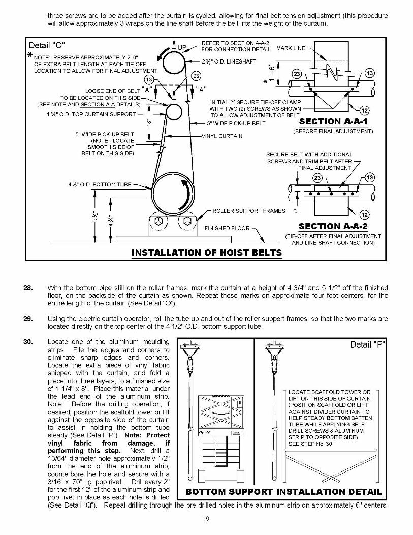

20
PIPE CAP
ATTACHMENT OF ALUMINUM MOULDING STRIPS
412" O.D. BOTTOM TUBE
24
6 EQUAL SPACES @ 2" = 12"
Detail "Q"
12"
ALUMINUM MOULDING
114" x 8" VINYL
FABRIC - 3 LAYERS
(PROVIDED)
13
END OF VINYL CURTAIN
23 3/16" x .70 Lg. POP RIVET
Continue with additional aluminum strips to the opposite end of the curtain taking care to ensure the pop rivet pin is completely removed from the rivet. Should the pin break off, drive the remainder of the pin into the batten tube.
31. As you come near the opposite end of the curtain, check to see if a short piece of aluminum moulding strip is
required. Should a short piece be required, place it between the last two full-length pieces, so that a short piece is not located at the very end. Repeat Step No. 30 and refer to Detail “Q” for attachment of the aluminum moulding strip at this end of the curtain. Brush or vacuum all drill chips from the divider curtain and the floor area. Lower the curtain to remove additional drill chips that are in the fabric crease.
32. Operate the curtain up and down several times, while carefully observing the tracking of the belts on the line
shaft. Belts may need to be adjusted if the curtain is not rolling up evenly. If not tracking properly, lower the curtain until the belts are slack. This will allow the belts to self-center. Also make certain the belt tie-off to the line shaft and top pipe support are in perfect alignment. Adjust the top pipe tie-off to the left or right as necessary.
33. The No. 675 Divider Curtain, with the hoist belts properly adjusted, should be even across its entire length when
in the stored position. If this is not the case, and the hoist belts are equal in length, it may be necessary to shim the belt roll-up. Be certain the line shaft is level first before proceeding with shimming the belts (See Detail “R”).
• Lower the curtain to the down position and allow additional wraps of belting to unwind off the line shaft, as shown in Detail "S", until belt attachment screws are exposed. Cut a short section (8" to 12") of scrap belt, and wedge in place between the hoist belt and the line shaft as shown.
• Hoist the curtain to the storage position and check the level of the curtain. Should the curtain straps remain too long in the storage position, repeat previous step and increase the shim belt length as required until the curtain is level in the storage position. The shim straps may need to be longer. If any hoist straps are pulling too tight, lower the curtain to the down position and trim some of the material off of the shim strap. Adjust the shim straps until the bottom of the divider curtain is level when in the up or storage position.
34. Set the Up and Down Rotary Limit Switch. Refer to pages 20 and 21 for complete limit switch setting instructions,
and/or the instructions included with the electric winch operator. IMPORTANT NOTE – The down limit switch must be set to allow the curtain to hang freely, without any support from the belts after all of the final adjustments have been made. This will allow the belts to self center, should the belt be pulled off center by an unsupervised individual.

21
Detail "S"
1
LINESHAFTBELT SHIM
INSTALLATION OF BELT SHIMS
HOIST BELTHOIST BELT
2LINESHAFT
BELT SHIM
HOIST BELT AND
SHIM TIGHT TO
LINESHAFT
3
Detail "R"
INSTALLATION OF BELT SHIMS
When this condition exists, the belt shims are required at belts 1 and 4.
When this condition exists, the belt shims are required at belts 2 and 3.
Figure D
Belt 1 is of a different length or thickness, or the line shaft tie-off is not aligned with
the other belt tie-offs, causing it to increase its diameter on the pull-up drum faster
than the remaining belts. This results in the curtain hanging unevenly when raised
to a stored position. To eliminate this condition, belt shims are required at belts 2, 3
and 4 to allow their overall diameters to be equal to belt 1 when in a raised position.
Figure C
Figure B
Illustrates a 675 in the proper stored position. All hoist belts are equal in length and
thickness, allowing the curtain to be supported evenly.
JoistFigure A
1 Hoist Belt 2 3 4
2'-0"
RE
F.
Joist
Joist
1 2 3 4
Joist
1 2 3 4
1 2 3 4

22
5
8
1
NO
RM
ALLY
PRESSURE
LOCK
GUIDE
PLATE
TOMOTOR
RED
BLACK
WHITE
CLO
SE
D
CO
MM
ON
UP
Detail "AA"MOTOR
CONNECTIONS
WWHITE
X
Y
G
DOWN
CO
MM
ON
NO
RM
ALLY
TRAVELING
NUTS
CLO
SE
D
GREEN
POWERCORD
BLACK
RED
PLUG
CONNECTIONS
LIMIT SWITCH DUAL OUTPUT WIRING DETAIL
FINAL ADJUSTMENTS 35. Energize the winch (either by the key switch or “Cheater” Box), to raise the curtain no more than two feet off the
ground. Inspect each belt to ensure that each belt is aligned and that all of the slack is out of belt pick up lines. Now check that the curtain is plumb, and level to the floor. Leveling and relieving any slack in any of the belt pick up lines can be done by loosening or tightening the belt with the tie off on the top of the curtain (See Detail "O"). After adjustments are made, cycle the curtain up and down to ensure proper adjustments have been made. Once the curtain is plumb and level, (See Detail "R") lower the curtain and start your final adjustments. The final adjustment stage consists of the following:
Ensure a minimum of three wraps of belting are on the line shaft at each pick up location with the curtain 1 1/2"
above the finished floor. Closing all “S” hooks. (26) Closing all Turnbuckles. (15)
Check to make sure that all of the strap plates and belts are secured to the line shaft with the proper number of
self drilling screws. At this time install the three additional screws at the belt tie-off, and cut excess strap (See Details “E” and “O”).
ADJUSTMENT INSTRUCTIONS FOR UP AND DOWN ROTARY COUNTING LIMIT SWITCH
1. With curtain in the down position (approximately 1 1/2” off of the finished floor) double-check the following:
A. Belts are wrapped on line shaft in the proper direction per instructions. B. There are a minimum of three wraps of belting on the line shaft at each pick up point, with the curtain in the down
position. 2. Check to ensure that the hardware that secures the micro switches in the box is fully tightened. IT WILL NOT BE
POSSIBLE TO MOVE THESE SWITCHES – all adjustments will be made by moving the traveling nuts left or right, as in Steps No. 3 and 5.

23
THIS PRINT IS THE PROPERTY OF PORTER ATHLETIC EQUIPMENT COMPANY AND MAY NOT BE REPRODUCED WITHOUT WRITTEN PERMISSION
THIS WARNING IS GIVEN IN COMPLIANCE WITH CALIFORNIA’S PROPOSITION 65:
WARNING This product contains chemicals known to the
State of California to cause cancer, birth defects

24
INSTALLER NOTES


