1 w w w . n i t r o g a s . c o m
Roller Cam
α
+
−
Pres
s St
roke
Cam Stroke50°
-50º
-40º
-30º
-20º
-10º
10 20 30 40 50 60 70 80 90 100
10º
0º
0
20
40
60
80
100
120
140
160
180
200
0
15º
α
ekorts sserP
Cam stroke
NITROGAS Roller Cams are compact and cost effective. Designed for a long service life, since the wear surfaces are mounted with Aluminium-Bronze alloy with graphite against steel surfaces hardened to 55-60 HRC.
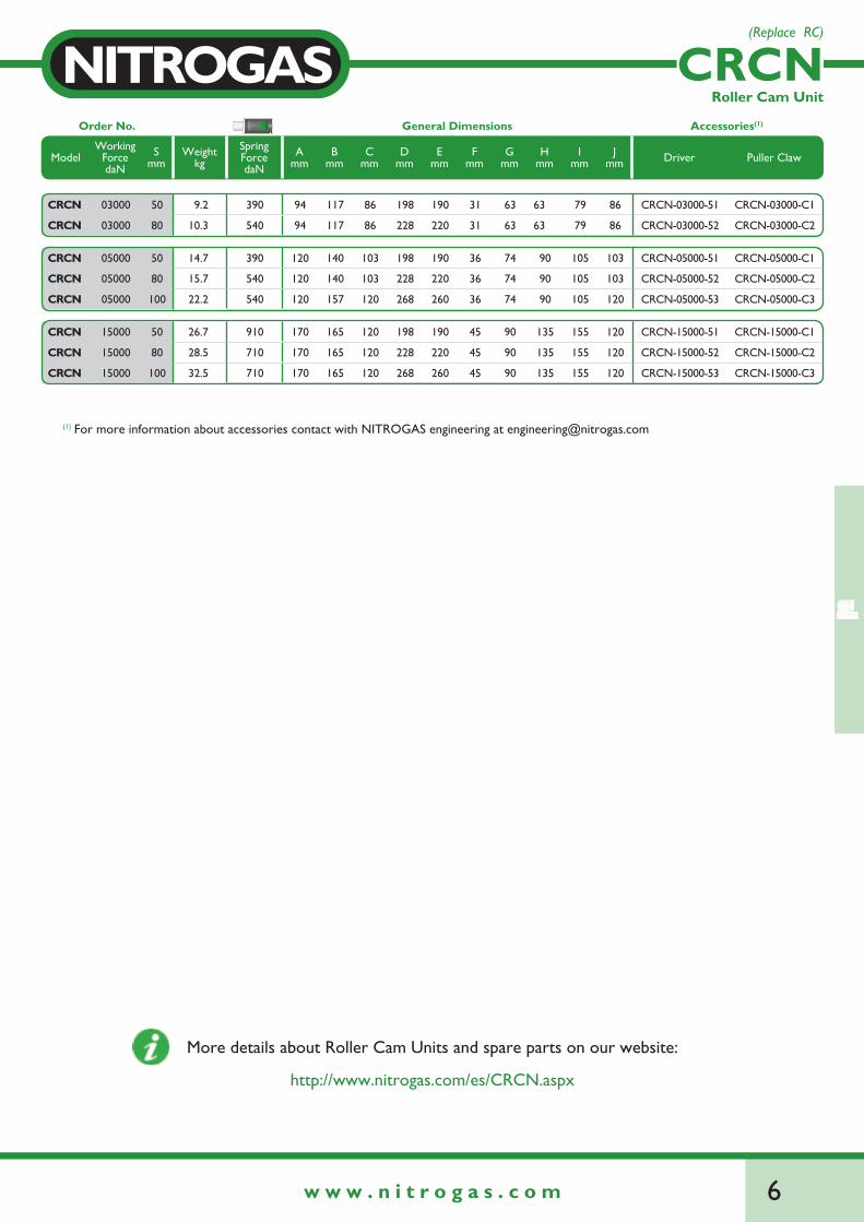
As the movement of the press is transformed by a roller, the roller cams are applicable for longer strokes (50-100 mm) and for loads up to 20000 daN. Nominal forces of 2000 daN, 3000 daN, 5000 daN, 15000 daN and 20000 daN are available.
Roller Cams are recommended in case of long strokes and little space. Due to the guiding type they are not recommended for heavy asymmetric loads (see Working Force Distribution on the side page).
The cam units are fitted with gas springs to provide the return force and ensure the return of the body.All models has an easy access to the return spring (see Gas Spring extraction below).
NITROGAS offers engineering support referring to cam applications for die designers and builders.
CAD files of Roller Cams can be downloaded for FREE from our website: www.nitrogas.com
Cam Diagram
Gas spring extractionThe dismounting of the gas spring allows an easier movement of the cam slide at the adjustment of the Roller Cam Unit.
Remove the screws.STEP 1
Remove the gas spring.STEP 2
The press stroke depends on the assembly angle (a) of the Roller Cam Unit.
2w w w . n i t r o g a s . c o m
Roller Cam
Working Force
100% 10%80% 50%The center of the load must be located as much centered as possible.
Working force distribution
Example of work
Maximum press speed ...................................... 1.6 m/sMaximum cadence (at 20ºC) ........................... 40 strokes/min
Spare parts available for all the Roller Cams.
3 w w w . n i t r o g a s . c o m
Mounting area Overall Dimensions
ModelWorking ForcedaN
Smm
Hmm
Gmm
SpringForcedaN
Widthmm
Heightmm
Lengthmm
Weightkg
CR
CN
0300050
63 63390
94 117190 9.2
80 540 220 10.3
05000
50
90 74
390
120140
190 14.7
80540
220 15.7
100 157 260 22.2
15000
50
135 90
910
170 165
190 26.7
80710
220 28.5
100 260 32.5
CR
CS
0200022
50 50180
75 85115 3
35 190 136 3.7
03000
50
68 63450
100 117
200 10.7
80 230 11.1
100 540 260 16.9
05000
50
88 74450
120 140
200 15.4
80 230 17
100 540 260 18.3
15000
50
132 92910
170 165
220 28.8
80 250 29
100 710 270 29.8
20000
50
196 110 1200 240 205
250 61.8
80 280 62.1
100 300 65.4
Roller Cam
Width
Height
Length
Mounting area G
H
Roller cams overview
5 w w w . n i t r o g a s . c o m
CRCN
If placed in horizontal position:1 mm. press stroke = 0.85. cam stroke
CAM DIAGRAM
PRES
S ST
ROKE
CAM STROKE
B
=
I
=
A
H
CJ
S
D
E
REFERENCE PIN (RP)
G
S
50º
50º
F
±0.0
5
±0.0
2
Driver
Puller claw
50°
50°
15°
50°
DRIVER* PULLER CLAW
WEB
CAD
Roller Cam Unit
If a reference pin is required, mark it in the order as it is shown in the ordering example.
Ordering example: (with reference pin)(without reference pin)
4 x CRCN-03000-50 - RP4 x CRCN-03000-50
Optional accessories
Driver for installation angle 0º. For any other installation angle, contact with NITROGAS engineering.*
Maximun inclination angle
CRCN-03000-51
See dimensions on page 28.
CRCN-03000-C1
(Replace RC)
Ordering example: Ordering example:
6w w w . n i t r o g a s . c o m
Order No. General Dimensions Accessories(1)
ModelWorking
ForcedaN
Smm
Weightkg
Spring ForcedaN
Amm
Bmm
Cmm
Dmm
Emm
Fmm
Gmm
Hmm
Imm
Jmm Driver Puller Claw
CRCN 03000 50 9.2 390 94 117 86 198 190 31 63 63 79 86 CRCN-03000-51 CRCN-03000-C1
CRCN 03000 80 10.3 540 94 117 86 228 220 31 63 63 79 86 CRCN-03000-52 CRCN-03000-C2
CRCN 05000 50 14.7 390 120 140 103 198 190 36 74 90 105 103 CRCN-05000-51 CRCN-05000-C1
CRCN 05000 80 15.7 540 120 140 103 228 220 36 74 90 105 103 CRCN-05000-52 CRCN-05000-C2
CRCN 05000 100 22.2 540 120 157 120 268 260 36 74 90 105 120 CRCN-05000-53 CRCN-05000-C3
CRCN 15000 50 26.7 910 170 165 120 198 190 45 90 135 155 120 CRCN-15000-51 CRCN-15000-C1
CRCN 15000 80 28.5 710 170 165 120 228 220 45 90 135 155 120 CRCN-15000-52 CRCN-15000-C2
CRCN 15000 100 32.5 710 170 165 120 268 260 45 90 135 155 120 CRCN-15000-53 CRCN-15000-C3
CRCN
G-1
500-
80M
ax. P
resi
on c
arga
149
bar
Fuer
za: 1
500
daN
art.
3.3
PED
97/
23/C
EH
Y43
6
Roller Cam Unit
For more information about accessories contact with NITROGAS engineering at [email protected](1)
(Replace RC)
http://www.nitrogas.com/es/CRCN.aspx
More details about Roller Cam Units and spare parts on our website:
7 w w w . n i t r o g a s . c o m
CRCS
A
H
B
G
CREFERENCE PIN (RP)
E
D
S
CAM DIAGRAM
If placed in horizontal position:1 mm. press stroke = 0.85. cam stroke
PRES
S ST
ROKE
CAM STROKES
50º
50º
J
=
I
=
F
±0.0
5
±0.0
2
Puller claw
Driver
50°
50°
15°
50°
DRIVER* PULLER CLAW
WEB
CAD
Roller Cam Unit
If a reference pin is required, mark it in the order as it is shown in the ordering example.
Ordering example: (with reference pin)(without reference pin)
4 x CRCS-03000-80 - RP4 x CRCS-03000-80
Optional accessories
Driver for installation angle 0º. For any other installation angle, contact with NITROGAS engineering.*
Maximun inclination angle
CRCS-03000-52 CRCS-03000-C2
See dimensions on page 28.
Ordering example: Ordering example:
8w w w . n i t r o g a s . c o m
CRCS 03000 50 10.7 450 100 117 86 208 200 31 63 68 82 86 CRCS-03000-51 CRCS-03000-C1
CRCS 03000 80 11.1 450 100 117 86 238 230 31 63 68 82 86 CRCS-03000-52 CRCS-03000-C2
CRCS 03000 100 16.9 540 100 117 110 258 260 31 63 68 82 86 CRCS-03000-53 CRCS-03000-C3
CRCS 05000 50 15.4 450 120 140 103 208 200 36 74 88 102 103 CRCS-05000-51 CRCS-05000-C1
CRCS 05000 80 17 450 120 140 103 238 230 36 74 88 102 103 CRCS-05000-52 CRCS-05000-C2
CRCS 05000 100 18.3 540 120 140 103 258 260 36 74 88 102 103 CRCS-05000-53 CRCS-05000-C3
CRCS 15000 50 28.8 910 170 165 120 216 220 45 92 132 150 120 CRCS-15000-51 CRCS-15000-C1
CRCS 15000 80 29 910 170 165 120 246 250 45 92 132 150 120 CRCS-15000-52 CRCS-15000-C2
CRCS 15000 100 29.8 710 170 165 120 266 270 45 92 132 150 120 CRCS-15000-53 CRCS-15000-C3
CRCS 20000 50 61.8 1200 240 205 150 258 250 55 110 196 222 150 CRCS-20000-51 CRCS-20000-C1
CRCS 20000 80 62.1 1200 240 205 150 288 280 55 110 196 222 150 CRCS-20000-52 CRCS-20000-C2
CRCS 20000 100 65.4 1200 240 205 150 308 300 55 110 196 222 150 CRCS-20000-53 CRCS-20000-C3
Order No. General Dimensions Accessories(1)
ModelWorking
ForcedaN
Smm
Weightkg
Spring ForcedaN
Amm
Bmm
Cmm
Dmm
Emm
Fmm
Gmm
Hmm
Imm
Jmm Driver Puller Claw
CRCS 02000 22 3 180 75 85 63 103 115 23 50 50 63 63 CRCS-02000-51 CRCS-02000-C1
CRCS 02000 35 3.7 190 75 85 63 137 136 23 50 50 63 63 CRCS-02000-52 CRCS-02000-C2
CRCS
G-1
500-
80M
ax. P
resi
on c
arga
149
bar
Fuer
za: 1
500
daN
art.
3.3
PED
97/
23/C
EH
Y43
6
Roller Cam Unit
(1)
More details about Roller Cam Units and spare parts on our website:
For more information about accessories contact with NITROGAS engineering at [email protected]
http://www.nitrogas.com/es/CRCS.aspx
9 w w w . n i t r o g a s . c o m
ROLLER CAM DRIVEROrder No.
PULLER CLAWOrder No.
Amm
Bmm
Cmm
Dmm
Emm
Fmm
Gmm
Hmm
CRCN-03000-50 CRCN-03000-51 CRCN-03000-C1 170 150 163 41 33 79.1 23 8.5
CRCN-03000-80 CRCN-03000-52 CRCN-03000-C2 200 180 199 41 33 79.1 23 8.5
CRCN-05000-50 CRCN-05000-51 CRCN-05000-C1 170 150 163 45 44 84.5 28 8.5
CRCN-05000-80 CRCN-05000-52 CRCN-05000-C2 200 180 199 45 44 84.5 28 8.5
CRCN-05000-100 CRCN-05000-53 CRCN-05000-C3 220 200 223 45 44 84.5 28 8.5
CRCN-15000-50 CRCN-15000-51 CRCN-15000-C1 170 150 163 51 66 89.5 30 10.5
CRCN-15000-80 CRCN-15000-52 CRCN-15000-C2 200 180 199 51 66 89.5 30 10.5
CRCN-15000-100 CRCN-15000-53 CRCN-15000-C3 220 200 223 51 66 89.5 30 10.5
CRCS-02000-22 CRCS-02000-51 CRCS-02000-C1 105 87 98 32 25.5 61.4 15 6.5
CRCS-02000-35 CRCS-02000-52 CRCS-02000-C2 115 97 109 32 25.5 61.4 15 6.5
CRCS-03000-50 CRCS-03000-51 CRCS-03000-C1 170 150 163 41 35.5 80.3 23 8.5
CRCS-03000-80 CRCS-03000-52 CRCS-03000-C2 200 180 199 41 35.5 80.3 23 8.5
CRCS-03000-100 CRCS-03000-53 CRCS-03000-C3 220 200 223 41 35.5 80.3 23 8.5
CRCS-05000-50 CRCS-05000-51 CRCS-05000-C1 170 150 163 45 43 84.4 28 8.5
CRCS-05000-80 CRCS-05000-52 CRCS-05000-C2 200 180 199 45 43 84.4 28 8.5
CRCS-05000-100 CRCS-05000-53* CRCS-05000-C3 - - - - 43 84.4 28 8.5
CRCS-15000-50 CRCS-15000-51 CRCS-15000-C1 170 150 163 51 64.5 86.8 30 10.5
CRCS-15000-80 CRCS-15000-52 CRCS-15000-C2 200 180 199 51 64.5 86.8 30 10.5
CRCS-15000-100 CRCS-15000-53 CRCS-15000-C3 220 200 223 51 64.5 86.8 30 10.5
CRCS-20000-50 CRCS-20000-51 CRCS-20000-C1 170 150 163 65 98.1 96 35 10.5
CRCS-20000-80 CRCS-20000-52 CRCS-20000-C2 200 180 199 65 98.1 96 35 10.5
CRCS-20000-100 CRCS-20000-53 CRCS-20000-C3 220 200 223 65 98.1 96 35 10.5
Accessories
1919
.6*
* For CRCS-02000-22 and CRCS-02000-35 12.1mm
F
ØH
E G
D A
PULLER CLAWDRIVER
B25
150º
Min 10
M8
M10 M10
M10
C
50°
Roller Cam Unit
Driver ordering example:
Puller Claw ordering example:
CRCN-03000-51
CRCN-03000-C1
Note: Driver for installation angle 0º. For any other installation angle contact with NITROGAS engineering.
CR
CN
CR
CS
* CRCS-05000-53 special driver. For CRCS-05000-100 cam accessories contact with NITROGAS engineenirng.