for technical questions or replacement parts, please call 1-800-444-3353.
SKU 94835 For technical questions please call 1-800-444-3353 Page 2
specifications
Construction Formed and welded steel
Hydraulic Ram
Diameter1-1/2”
Air Pressure Range 80 - 120 PSI
Air Inlet Thread 1/4” x 18 NPT
Overall Dimensions55-3/8” L x 18-3/8” W x
23-1/4” H
Maximum Lift
Capacity6000 lb. (3 Tons)
Vertical Travel 10.6”
Pump Actuation Foot Pedal
Roller Assembly
Width
Minimum: 39-1/2”
Maximum: 55-3/8”
Net Weight 302 lb.
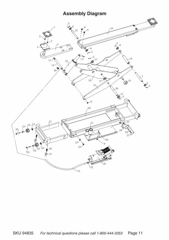
nOte: All part numbers mentioned in this manual refer to the Parts List on page 10 and the Assembly Diagram on page 11.
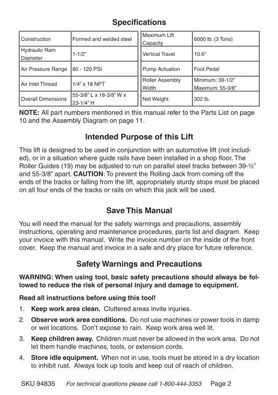
intended purpose of this lift
This lift is designed to be used in conjunction with an automotive lift (not includ-ed), or in a situation where guide rails have been installed in a shop floor. The Roller Guides (19) may be adjusted to run on parallel steel tracks between 39-½” and 55-3/8” apart. cAutiOn: To prevent the Rolling Jack from coming off the ends of the tracks or falling from the lift, appropriately sturdy stops must be placed on all four ends of the tracks or rails on which this jack will be used.
save this manual
You will need the manual for the safety warnings and precautions, assembly instructions, operating and maintenance procedures, parts list and diagram. Keep your invoice with this manual. Write the invoice number on the inside of the front cover. Keep the manual and invoice in a safe and dry place for future reference.
safety warnings and precautions
wArning: when using tool, basic safety precautions should always be fol-lowed to reduce the risk of personal injury and damage to equipment.
read all instructions before using this tool!
Keep work area clean. Cluttered areas invite injuries.
Observe work area conditions. Do not use machines or power tools in damp or wet locations. Don’t expose to rain. Keep work area well lit.
Keep children away. Children must never be allowed in the work area. Do not let them handle machines, tools, or extension cords.
store idle equipment. When not in use, tools must be stored in a dry location to inhibit rust. Always lock up tools and keep out of reach of children.
1.
2.
3.
4.
SKU 94835 For technical questions please call 1-800-444-3353 Page 3
use the right tool for the job. Do not attempt to force a small tool or attachment to do the work of a larger industrial tool. There are certain applications for which this tool was designed. It will do the job better and more safely at the rate for which it was intended. Do not modify this tool and do not use this tool for a purpose for which it was not intended.
dress properly. Do not wear loose clothing or jewelry as they can be caught in moving parts. Protective, electrically non-conductive clothes and non-skid footwear are recommended when working. Wear restrictive hair covering to contain long hair.
use eye and ear protection. Always wear ANSI approved impact safety goggles when working. Wear a full face shield if you are producing metal filings or wood chips. Wear an ANSI approved dust mask or respirator when working around metal, wood, and chemical dusts and mists.
do not overreach. Keep proper footing and balance at all times. Do not reach over or across running machines.
maintain tools with care. Keep tools maintained and clean for better and safer performance. Follow instructions for lubricating and changing accessories. The handles must be kept clean, dry, and free from oil and grease at all times.
remove adjusting keys and wrenches. Check that keys and adjusting wrenches are removed from the tool or machine work surface before beginning work.
Avoid unintentional operation. Be sure all safety precautions are followed, lift is secure and vehicle is properly positioned before operating this jack. Always think several steps ahead of your current operation to ensure safety.
stay alert. Watch what you are doing, use common sense. Do not operate any tool when you are tired or using any medication.
check for damaged parts. Before using any tool, any part that appears dam-aged should be carefully checked to determine that it will operate properly and perform its intended function. Check for alignment and binding of moving parts; any broken parts or mounting fixtures; noisy, loose or damaged roller guides (19); and any other condition that may affect proper operation. Any part that is damaged should be properly repaired or replaced by a qualified technician. Do not use the tool if any control does not operate properly.
replacement parts and accessories. When servicing, use only identical replacement parts. Use of any other parts will void the warranty. Only use ac-cessories intended for use with this tool. Approved parts and accessories are available from Harbor Freight Tools.
do not operate tool if under the influence of alcohol or drugs. Read warning labels on prescriptions to determine if your judgment or reflexes are impaired while taking drugs. If there is any doubt, do not operate the tool.
maintenance. For your safety, service and maintenance should be performed regularly by a qualified technician.
5.
6.
�.
8.
9.
10.
11.
12.
13.
14.
15.
16.
SKU 94835 For technical questions please call 1-800-444-3353 Page 4
the rails on which this jack will be used must be securely held in place and perfectly level and parallel. If either end of the rails is loose, closer or farther apart, higher or lower than the other, the jack could fall off the rails, bind with the rails, move or tip causing property damage, SeVeRe PeRSONAL INJURY OR DeATH. Due to the severe hazards created by improper rail setup, the installation must be done by a qualified technician.
use compressed air only. Never use any explosive gas or any other gas aside from compressed air as an energy source.
Keep the air hose off the rails and away from the rollers at all times. If an air hose is crushed, it can rupture resulting in personal injury.
this rolling bridge jack may cause a tripping hazard if installed in the floor of a workshop. Orange safety cones, a fence or other warning device should be used to warn of a tripping hazard.
the scissor Assembly may cause a pinch hazard. Use extreme caution to prevent any person, animal or equipment from being pinched in the scissor as-sembly during operation.
do not exceed the weight limit of this jack, which is 6000 lb. (3 tons). Over-loading may cause damage to the seals of the Foot Pedal Assembly (26) or Hydraulic Ram (12). Overloading may also cause the jack to fade or suddenly fail, allowing the vehicle to suddenly lower.
never try to lift an unbalanced load. An unbalanced load may suddenly pitch off the jack, causing serious injury or property damage.
warning: the warnings, cautions, and instructions discussed in this instruction manual cannot cover all possible conditions and situations that may occur. it must be understood by the operator that common sense and caution are factors which cannot be built into this product, but must be supplied by the operator.
1�.
18.
19.
20.
21.
22.
23.
SKU 94835 For technical questions please call 1-800-444-3353 Page 5
unpacking
When unpacking, check for damage. If any parts are missing or broken, please call Harbor Freight Tools at the number on the cover of this manual.
Assembly
Before initial use, this unit must first be installed on the automotive lift or rails (not included) on which it will be used. A pressurized air supply must be furnished. The hydraulic fluid level also must be checked before use.
before Operating this lift
installing the rolling jack on your automotive lift or rails.
1. The Roller Guides (19) are effectively wheels which will operate on rails much like the wheels on a railroad train. They will work on the edges of the platforms of an automotive lift, or on rails mounted on a work shop floor.
2. wArning: The automotive lift or rails on which this Rolling Jack will be mounted must be level, solid and capable of supporting more than the weight of this unit and any item that will be lifted by this jack. Serious personal or property damage may occur if the support provided for this jack fails during a lifting operation.
3. Loosen the four Bolts m10x25 (25). By pulling or pushing the Telescoping Frames (21), adjust the spacing of the Roller Guides (19) to match the spacing of your lift or rails. The Telescoping Frames (21) should be extended about the same amount, keeping the Lower Frame (20) centered in the assembly. Tighten the four Bolts m10x25 (25).
4. Place the Rolling Jack on your automotive lift or rails. Check its operation, and adjust the spacing of the Telescoping Frames (20) if necessary.
5. Install adequately sturdy and strong stops (not included) on both ends of each rail to ensure that the Rolling Jack cannot roll off the ends of the rails.
SKU 94835 For technical questions please call 1-800-444-3353 Page 6
supplying Air pressure to the rolling jack
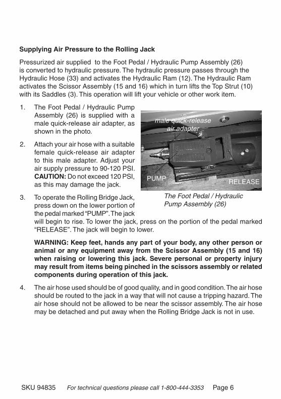
Pressurized air supplied to the Foot Pedal / Hydraulic Pump Assembly (26) is converted to hydraulic pressure. The hydraulic pressure passes through the Hydraulic Hose (33) and activates the Hydraulic Ram (12). The Hydraulic Ram activates the Scissor Assembly (15 and 16) which in turn lifts the Top Strut (10) with its Saddles (3). This operation will lift your vehicle or other work item.
1. The Foot Pedal / Hydraulic Pump Assembly (26) is supplied with a male quick-release air adapter, as shown in the photo.
2. Attach your air hose with a suitable female quick-release air adapter to this male adapter. Adjust your air supply pressure to 90-120 PSI. cAutiOn: Do not exceed 120 PSI, as this may damage the jack.
3. To operate the Rolling Bridge Jack, press down on the lower portion of the pedal marked “PUMP”. The jack will begin to rise. To lower the jack, press on the portion of the pedal marked “ReLeASe”. The jack will begin to lower.
wArning: Keep feet, hands any part of your body, any other person or animal or any equipment away from the scissor Assembly (15 and 16) when raising or lowering this jack. severe personal or property injury may result from items being pinched in the scissors assembly or related components during operation of this jack.
4. The air hose used should be of good quality, and in good condition. The air hose should be routed to the jack in a way that will not cause a tripping hazard. The air hose should not be allowed to be near the scissor assembly. The air hose may be detached and put away when the Rolling Bridge Jack is not in use.
The Foot Pedal / Hydraulic Pump Assembly (26)
male quick-release air adapter
PUMP ReLeASe
SKU 94835 For technical questions please call 1-800-444-3353 Page �
purging the Hydraulic ram
NOTe: Before first using this tool, the hydraulic ram must be purged.
1. To purge the Ram, first raise the Jack to its uppermost position, with no load.
2. When the Jack has been raised, remove the Filler Bolt from the Hydraulic Cylinder. Keeping your hands and tools clear, press the Foot Pedal down to attempt to raise the jack even higher.
3. When it is clear the Jack will not raise any higher, release the Foot Pedal.
4. Add good quality hydraulic oil into the opening in the Cylinder where the Filler Bolt has been removed. Fill until the Cylinder will hold no more oil.
5. Replace the Filler Bolt and its Seal Washer into the Cylinder, tighten firmly. Lower the Jack by pressing the ReLeASe portion of the Foot Pedal.
6. Check the condition of the Hydraulic Lift Table before each use. Raise and lower it several times before adding any load. Be sure that all controls work properly, and that it raises and lowers smoothly.
Operating the rolling bridge jack
nOtice: this jack is not to be used for any aircraft purpose.
1. Observing all safety precautions, drive the work vehicle over the Rolling Bridge Jack. Shut off the engine, put the vehicle in gear or park, and set the parking brake.
2. Connect your air hose to the male air quick-release adapter. Check that your air pressure regulator is set between 90 and 120 PSI.
3. Roll the Jack along its rails until it is positioned properly under the vehicle.
4. Pull out each Adjustable Arm Assembly (4) to position the Lift Pad (1) where desired under the vehicle. cAutiOn: Check with the vehicle manufacturer to determine approved lift points for each vehicle. Never attempt to lift a vehicle using unapproved lift points, or if the lift points are damaged or weakened by rust. Damaged or improper lift points may cause the vehicle to suddenly fall off the jack potentially causing serious personal or property injury.
SKU 94835 For technical questions please call 1-800-444-3353 Page 8
5. Press the “PUMP” portion of the Pedal (26) to raise the Lift Pads (1) enough to contact the lift points of the vehicle. Confirm that you have good contact in the right spot. If necessary, lower the jack and adjust the position of the Lift Pads before proceeding.
6. With the Lift Pads in the correct position, press the PUMP portion of the Foot Pedal long enough to raise the vehicle approximately one inch, just enough to take the weight of the vehicle on the jack. Check to be sure the load is balanced, and that by further lifting there is no danger of damage to the vehicle or to any nearby tools or property.
�. After ensuring that it is safe to do so, press the PUMP portion of the Foot Pedal to raise the vehicle to the desired height.
8. Place safety jack stands (not included) under the vehicle to prevent the vehicle falling in case the jack should lower unexpectedly.
wArning: never go under a raised vehicle unless there are safety jack stands in place.
nOte: This jack is intended for temporarily lifting and lowering a vehicle or similar work load. It is not for storage or for transporting loads. Do not leave an item on the jack for an extended period of time, damage to the jack or to other property may result. Do not attempt to transport any load on this jack, severe personal or property damage may result.
9. To lower the vehicle, first ensure that all persons, animals and property are safely away from the vehicle. Be sure nothing is near the scissor assembly. Remove the safety jack stands.
10. Lower the vehicle by pressing the “ReLeASe” portion of the Pedal Assembly. Control the speed of lowering to ensure safety and that the vehicle will rest solidly on the ground.
11. With the vehicle safely on the ground, push the Adjustable Arms (4) back into Top Strut (10).
12. Disconnect the air hose, and place the air hose clear of the vehicle.
13. Drive the vehicle off the Jack.
SKU 94835 For technical questions please call 1-800-444-3353 Page 9
maintenance
1. Periodically check to be sure the Roller Guides are properly adjusted to the track or rail on which the jack is mounted. Check to be sure the stops (not included) at the ends of the rails are secure and in good condition. Check to be sure the rails are secure, stable, parallel and level. Check to be sure the Bolts m10x25 (25) are secure.
2. Periodically check the air and hydraulic fittings and Hydraulic Hose (33) for leaks. Repair if any leak is detected.
3. Periodically lubricate all moving points of the Rolling Jack, including, but not limited to Adjustable Arms (4), Roller Axle (�), Lower Axle (14), Flat Washer (1�), Roller Guide (19), Slider Shaft (22), Scissor Assembly Axle (30), and Sleeve Bushings (34).
4. The piston of the Hydraulic Ram (12) should be kept clean, free of dirt and water, and protected from corrosion.
troubleshooting
1. If the jack fails to lift, or fades under load, check the air connection, hydraulic connectors and Hydraulic Hose (33) for leaks.
2. If no leaks are detected, have a qualified service person inspect the Foot Pedal / Hydraulic Pump Assembly (26) and Hydraulic Ram (12) for faults.
SKU 94835 For technical questions please call 1-800-444-3353 Page 10
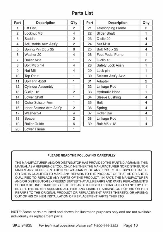
parts list
nOte: Some parts are listed and shown for illustration purposes only and are not available individually as replacement parts.
part description Q’ty
1 Lift Pad 2
2 Locknut M6 4
3 Saddle 2
4 Adjustable Arm Ass’y 2
5 Spring Pin Ø5 x 35 6
6 Washer 20 4
� Roller Axle 1
8 Bolt M8 x 14 4
9 Nut M6 4
10 Top Strut 1
11 Split Pin 4x50 1
12 Cylinder Assembly 1
13 C-clip 15 2
14 Lower Shaft 1
15 Outer Scissor Arm 1
16 Inner Scissor Arm Ass’y 2
1� Washer 24 4
18 Spacer 2
19 Roller Guide 6
20 Lower Frame 1
part description Q’ty
21 Telescoping Frame 2
22 Slider Shaft 1
23 C-clip 20 4
24 Nut M10 4
25 Bolt M10 x 25 4
26 Foot Pedal Pump 1
2� C-clip 18 2
28 Safety Lock Ass’y 1
29 Lock pin 1
30 Scissor Ass’y Axle 1
31 Adapter 2
32 Linkage Rod 1
33 Hydraulic Hose 1
34 Sleeve Bushing 4
35 Bolt 4
36 Spring 4
3� Roller Bar 4
38 Linkage Rod 1
39 Bolt M6 x 12 4
pleAse reAd tHe fOllOwing cArefully
THe MANUFACTUReR AND/OR DISTRIBUTOR HAS PROVIDeD THe PARTS DIAGRAM IN THIS MANUAL AS A ReFeReNCe TOOL ONLY. NeITHeR THe MANUFACTUReR NOR DISTRIBUTOR MAKeS ANY RePReSeNTATION OR WARRANTY OF ANY KIND TO THe BUYeR THAT He OR SHe IS QUALIFIeD TO MAKe ANY RePAIRS TO THe PRODUCT OR THAT He OR SHe IS QUALIFIeD TO RePLACe ANY PARTS OF THe PRODUCT. IN FACT, THe MANUFACTUReR AND/OR DISTRIBUTOR eXPReSSLY STATeS THAT ALL RePAIRS AND PARTS RePLACeMeNTS SHOULD Be UNDeRTAKeN BY CeRTIFIeD AND LICeNSeD TeCHNICIANS AND NOT BY THe BUYeR. THe BUYeR ASSUMeS ALL RISK AND LIABILITY ARISING OUT OF HIS OR HeR RePAIRS TO THe ORIGINAL PRODUCT OR RePLACeMeNT PARTS THeReTO, OR ARISING OUT OF HIS OR HeR INSTALLATION OF RePLACeMeNT PARTS THeReTO.
SKU 94835 For technical questions please call 1-800-444-3353 Page 11
Assembly diagram
9
1
2
2
34
13
14
12
56
228
8
6
5
5
5
5
56
616 17
17
30
17
13
20
31
24
25
21
19
19
23
23
26
2729
28
19
7
18
15
11
10
32
33
34
3435
35
36
37
38
27
39
SKU 94835 For technical questions please call 1-800-444-3353 Page 12
Harbor Freight Tools Co. makes every effort to assure that its products meet high quality and durability standards, and warrants to the original purchaser that this product is free from defects in materials and workmanship for the period of ninety days from the date of purchase. This warranty does not apply to damage due directly or indirectly, to misuse, abuse, negligence or accidents, repairs or alterations outside our facilities, or to lack of maintenance. We shall in no event be liable for death, injuries to persons or property, or for incidental, contingent, special or consequential damages arising from the use of our product. Some states do not allow the exclusion or limitation of incidental or consequential damages, so the above limitation of exclusion may not apply to you. THiS WarranTy iS expreSSly in lieu oF all oTHer WarranTieS, expreSS or implied, inCluding THe WarranTieS oF merCHanTabiliTy and FiTneSS.
To take advantage of this warranty, the product or part must be returned to us with transportation charges prepaid. proof of purchase date and an explanation of the complaint must accompany the merchandise. if our inspection verifies the defect, we will either repair or replace the product at our election or we may elect to refund the purchase price if we cannot readily and quickly provide you with a replacement. We will return repaired products at our expense, but if we determine there is no defect, or that the defect resulted from causes not within the scope of our warranty, then you must bear the cost of returning the product.
This warranty gives you specific legal rights and you may also have other rights which vary from state to state.
3491 Mission Oaks Blvd. • PO Box 6009 • Camarillo, CA 93011 • (800) 444-3353