Catalog 219-2 RoofPak ® Singlezone, Heating and Cooling Systems with Evaporative Condensers Models: RDE/RPE 76–150 Tons RDE–SWSI Airfoil (Plenum); SAF Draw-Through Cooling Coil; Filters; Steam or Hot Water Heat RPE–DWDI Airfoil; SAF Blow-Through or Draw-Through Cooling Coil; Filters; Electric, Gas, Steam or Hot Water Heat
Transcript
Catalog 219-2RoofPak®
Singlezone, Heating and Cooling Systems with Evaporative CondensersModels: RDE/RPE 76–150 Tons
RDE–SWSI Airfoil (Plenum); SAF Draw-Through Cooling Coil; Filters; Steam or Hot Water Heat
RPE–DWDI Airfoil; SAF Blow-Through or Draw-Through Cooling Coil; Filters; Electric, Gas, Steam or Hot Water Heat
CAT 219-2 • ROOFPAK PACKAGED SYSTEMS 2 www.DaikinApplied.com
www.DaikinApplied.com 3 CAT 219-2 • ROOFPAK PACKAGED SYSTEMS
InTroduCTIon
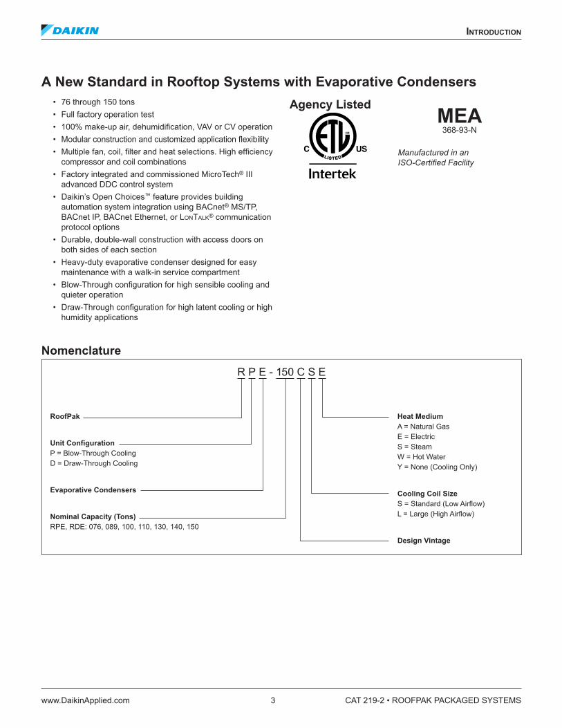
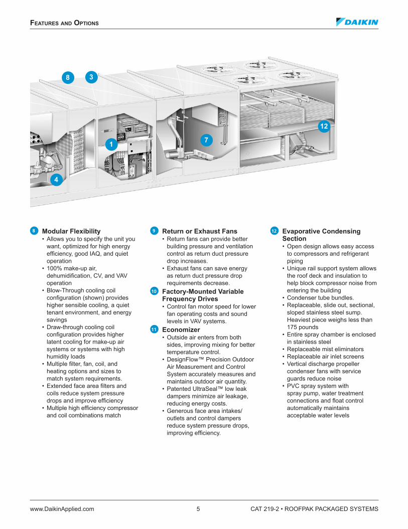
A New Standard in Rooftop Systems with Evaporative Condensers• 76 through 150 tons• Full factory operation test• 100% make-up air, dehumidification, VAV or CV operation• Modular construction and customized application flexibility• Multiple fan, coil, filter and heat selections. High efficiency
compressor and coil combinations• Factory integrated and commissioned MicroTech® III
advanced DDC control system• Daikin’s Open Choices™ feature provides building
automation system integration using BACnet® MS/TP, BACnet IP, BACnet Ethernet, or LonTaLk® communication protocol options
• Durable, double-wall construction with access doors on both sides of each section
• Heavy-duty evaporative condenser designed for easy maintenance with a walk-in service compartment
• Blow-Through configuration for high sensible cooling and quieter operation
• Draw-Through configuration for high latent cooling or high humidity applications
Agency Listed MEA
368-93-N
Manufactured in an ISO-Certified Facility
Nomenclature
R P E - 150 C S E
RoofPak
Unit Configuration P = Blow-Through Cooling D = Draw-Through Cooling
Heat Medium A = Natural Gas E = Electric S = Steam W = Hot Water Y = None (Cooling Only)
Cooling Coil Size S = Standard (Low Airflow) L = Large (High Airflow)
Design Vintage
CAT 219-2 • ROOFPAK PACKAGED SYSTEMS 4 www.DaikinApplied.com
feaTures and opTIons
feaTures and opTIons
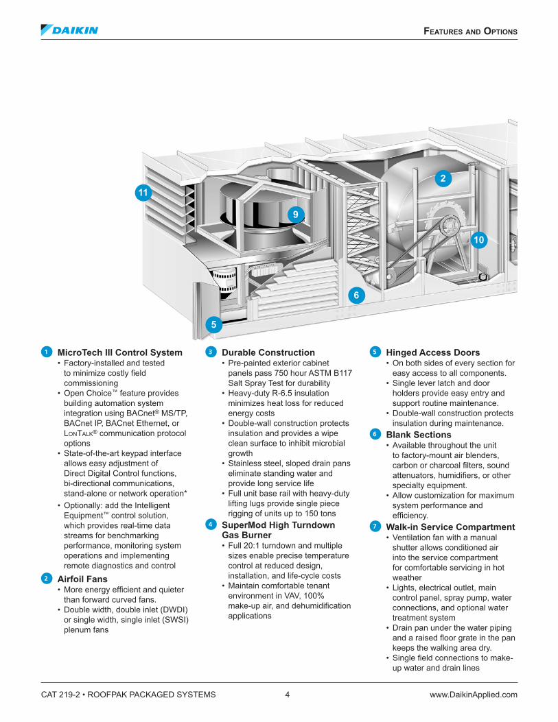
1 MicroTech III Control System• Factory-installed and tested
to minimize costly field commissioning
• Open Choice™ feature provides building automation system integration using BACnet® MS/TP, BACnet IP, BACnet Ethernet, or LonTaLk® communication protocol options
• State-of-the-art keypad interface allows easy adjustment of Direct Digital Control functions, bi-directional communications, stand-alone or network operation*
• Optionally: add the Intelligent Equipment™ control solution, which provides real-time data streams for benchmarking performance, monitoring system operations and implementing remote diagnostics and control
2 Airfoil Fans• More energy efficient and quieter
than forward curved fans.• Double width, double inlet (DWDI)
• PVC spray system with spray pump, water treatment connections and float control automatically maintains acceptable water levels
8
12
7
4
1
3
CAT 219-2 • ROOFPAK PACKAGED SYSTEMS 6 www.DaikinApplied.com
energy savIngs
energy savIngs
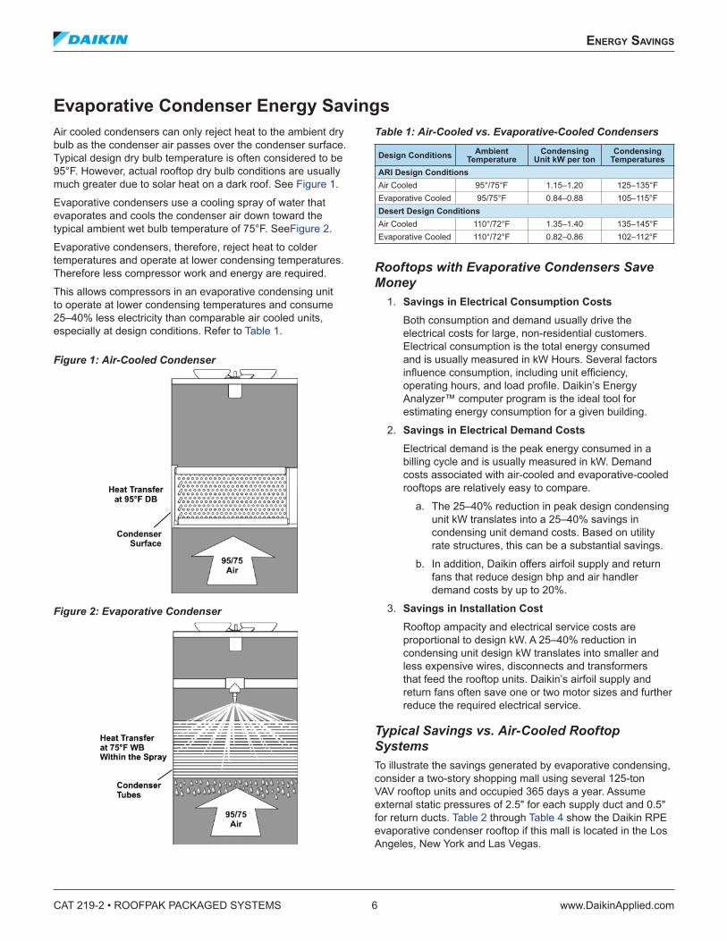
Evaporative Condenser Energy SavingsAir cooled condensers can only reject heat to the ambient dry bulb as the condenser air passes over the condenser surface. Typical design dry bulb temperature is often considered to be 95°F. However, actual rooftop dry bulb conditions are usually much greater due to solar heat on a dark roof. See Figure 1.
Evaporative condensers use a cooling spray of water that evaporates and cools the condenser air down toward the typical ambient wet bulb temperature of 75°F. SeeFigure 2.
Evaporative condensers, therefore, reject heat to colder temperatures and operate at lower condensing temperatures. Therefore less compressor work and energy are required.
This allows compressors in an evaporative condensing unit to operate at lower condensing temperatures and consume 25–40% less electricity than comparable air cooled units, especially at design conditions. Refer to Table 1.
Figure 1: Air-Cooled Condenser
Figure 2: Evaporative Condenser
Table 1: Air-Cooled vs. Evaporative-Cooled Condensers
1. Savings in Electrical Consumption CostsBoth consumption and demand usually drive the electrical costs for large, non-residential customers. Electrical consumption is the total energy consumed and is usually measured in kW Hours. Several factors influence consumption, including unit efficiency, operating hours, and load profile. Daikin’s Energy Analyzer™ computer program is the ideal tool for estimating energy consumption for a given building.
2. Savings in Electrical Demand CostsElectrical demand is the peak energy consumed in a billing cycle and is usually measured in kW. Demand costs associated with air-cooled and evaporative-cooled rooftops are relatively easy to compare.
a. The 25–40% reduction in peak design condensing unit kW translates into a 25–40% savings in condensing unit demand costs. Based on utility rate structures, this can be a substantial savings.
b. In addition, Daikin offers airfoil supply and return fans that reduce design bhp and air handler demand costs by up to 20%.
3. Savings in Installation CostRooftop ampacity and electrical service costs are proportional to design kW. A 25–40% reduction in condensing unit design kW translates into smaller and less expensive wires, disconnects and transformers that feed the rooftop units. Daikin’s airfoil supply and return fans often save one or two motor sizes and further reduce the required electrical service.
Typical Savings vs. Air-Cooled Rooftop SystemsTo illustrate the savings generated by evaporative condensing, consider a two-story shopping mall using several 125-ton VAV rooftop units and occupied 365 days a year. Assume external static pressures of 2.5" for each supply duct and 0.5" for return ducts. Table 2 through Table 4 show the Daikin RPE evaporative condenser rooftop if this mall is located in the Los Angeles, New York and Las Vegas.
energy savIngs
www.DaikinApplied.com 7 CAT 219-2 • ROOFPAK PACKAGED SYSTEMS
Table 2: Comparison of Evaporative and Air-Cooled Condensing for the Los Angeles Area MallConditions Air-Cooled Daikin RPEDesign Ambient Dry Bulb/Wet Bulb 95°F/72°F 95°F/72°FElectrical Consumption Rate (per kW Hour) $0.15 $0.15
Electrical Demand Rate (per kW) $24 $24
Condensing UnitEfficiency (kW/ton) 1.15 0.85
Electrical Cost $30,200 $22,100Percent Savings 27%All shopping mall energy analysis and comparison charts provided in this document have been generated using Daikin Energy Analyzer™ software.
Table 3: Comparison of Evaporative and Air-Cooled Condensing for the New York Area MallConditions Air-Cooled Daikin RPEDesign Ambient Dry Bulb/Wet Bulb 95°F/75°F 95°F/75°FElectrical Consumption Rate (per kW Hour) $0.11 $0.11Electrical Demand Rate (per kW) $18 $18
Percent Savings 31%All shopping mall energy analysis and comparison charts provided in this document have been generated using Daikin Energy Analyzer™ software.
Table 4: Comparison of Evaporative and Air-Cooled Condensing for the Las Vegas AreaConditions Air-Cooled Daikin RPEDesign Ambient Dry Bulb/Wet Bulb 110°F/72°F 110°F/72°FElectrical Consumption Rate (per kW Hour) $0.07 $0.07Electrical Demand Rate (per kW) $8 $8
Percent Savings 40%All shopping mall energy analysis and comparison charts provided in this document have been generated using Daikin Energy Analyzer™ software.
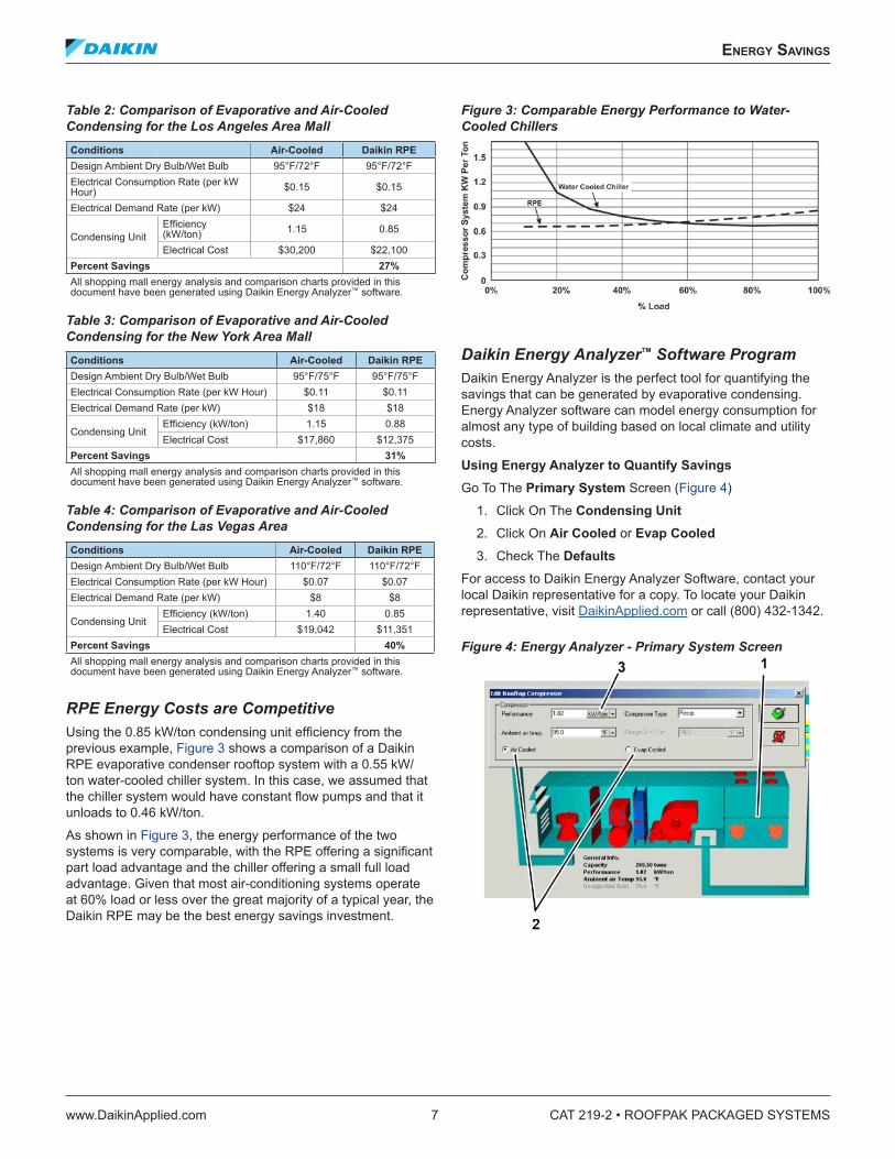
RPE Energy Costs are CompetitiveUsing the 0.85 kW/ton condensing unit efficiency from the previous example, Figure 3 shows a comparison of a Daikin RPE evaporative condenser rooftop system with a 0.55 kW/ton water-cooled chiller system. In this case, we assumed that the chiller system would have constant flow pumps and that it unloads to 0.46 kW/ton.
As shown in Figure 3, the energy performance of the two systems is very comparable, with the RPE offering a significant part load advantage and the chiller offering a small full load advantage. Given that most air-conditioning systems operate at 60% load or less over the great majority of a typical year, the Daikin RPE may be the best energy savings investment.
Figure 3: Comparable Energy Performance to Water-Cooled Chillers
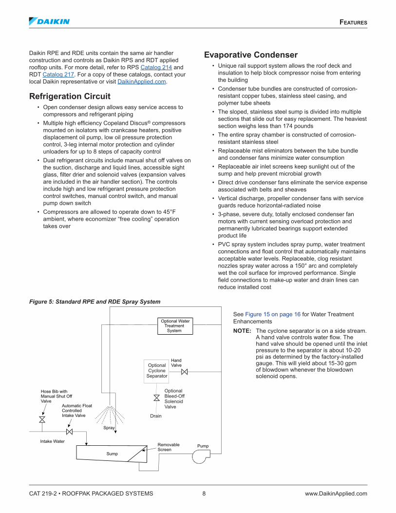
Daikin Energy Analyzer™ Software ProgramDaikin Energy Analyzer is the perfect tool for quantifying the savings that can be generated by evaporative condensing. Energy Analyzer software can model energy consumption for almost any type of building based on local climate and utility costs.
Using Energy Analyzer to Quantify SavingsGo To The Primary System Screen (Figure 4)
1. Click On The Condensing Unit2. Click On Air Cooled or Evap Cooled3. Check The Defaults
For access to Daikin Energy Analyzer Software, contact your local Daikin representative for a copy. To locate your Daikin representative, visit DaikinApplied.com or call (800) 432-1342.
CAT 219-2 • ROOFPAK PACKAGED SYSTEMS 8 www.DaikinApplied.com
feaTures
feaTures
Daikin RPE and RDE units contain the same air handler construction and controls as Daikin RPS and RDT applied rooftop units. For more detail, refer to RPS Catalog 214 and RDT Catalog 217. For a copy of these catalogs, contact your local Daikin representative or visit DaikinApplied.com.
Refrigeration Circuit• Open condenser design allows easy service access to
compressors and refrigerant piping• Multiple high efficiency Copeland Discus® compressors
mounted on isolators with crankcase heaters, positive displacement oil pump, low oil pressure protection control, 3-leg internal motor protection and cylinder unloaders for up to 8 steps of capacity control
• Dual refrigerant circuits include manual shut off valves on the suction, discharge and liquid lines, accessible sight glass, filter drier and solenoid valves (expansion valves are included in the air handler section). The controls include high and low refrigerant pressure protection control switches, manual control switch, and manual pump down switch
• Compressors are allowed to operate down to 45°F ambient, where economizer “free cooling” operation takes over
Evaporative Condenser• Unique rail support system allows the roof deck and
insulation to help block compressor noise from entering the building
• Condenser tube bundles are constructed of corrosion- resistant copper tubes, stainless steel casing, and polymer tube sheets
• The sloped, stainless steel sump is divided into multiple sections that slide out for easy replacement. The heaviest section weighs less than 174 pounds
• The entire spray chamber is constructed of corrosion- resistant stainless steel
• Replaceable mist eliminators between the tube bundle and condenser fans minimize water consumption
• Replaceable air inlet screens keep sunlight out of the sump and help prevent microbial growth
• Direct drive condenser fans eliminate the service expense associated with belts and sheaves
• Vertical discharge, propeller condenser fans with service guards reduce horizontal-radiated noise
• 3-phase, severe duty, totally enclosed condenser fan motors with current sensing overload protection and permanently lubricated bearings support extended product life
• PVC spray system includes spray pump, water treatment connections and float control that automatically maintains acceptable water levels. Replaceable, clog resistant nozzles spray water across a 150° arc and completely wet the coil surface for improved performance. Single field connections to make-up water and drain lines can reduce installed cost
Figure 5: Standard RPE and RDE Spray System
Optional WaterTreatmentSystem
HandValve
RemovableScreen
Pump
Sump
Automatic FloatControlledIntake Valve
Hose Bib withManual Shut OffValve
Intake Water
Spray
OptionalCycloneSeparator
Drain
OptionalBleed-OffSolenoidValve
See Figure 15 on page 16 for Water Treatment EnhancementsNOTE: The cyclone separator is on a side stream.
A hand valve controls water flow. The hand valve should be opened until the inlet pressure to the separator is about 10-20 psi as determined by the factory-installed gauge. This will yield about 15-30 gpm of blowdown whenever the blowdown solenoid opens.
www.DaikinApplied.com 9 CAT 219-2 • ROOFPAK PACKAGED SYSTEMS
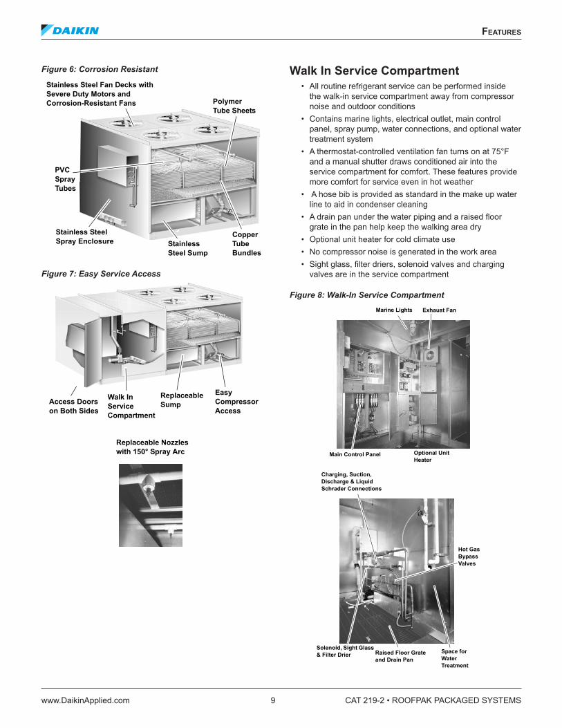
Figure 6: Corrosion Resistant
Figure 7: Easy Service Access
Walk In Service Compartment• All routine refrigerant service can be performed inside
the walk-in service compartment away from compressor noise and outdoor conditions
• Contains marine lights, electrical outlet, main control panel, spray pump, water connections, and optional water treatment system
• A thermostat-controlled ventilation fan turns on at 75°F and a manual shutter draws conditioned air into the service compartment for comfort. These features provide more comfort for service even in hot weather
• A hose bib is provided as standard in the make up water line to aid in condenser cleaning
• A drain pan under the water piping and a raised floor grate in the pan help keep the walking area dry
• Optional unit heater for cold climate use• No compressor noise is generated in the work area• Sight glass, filter driers, solenoid valves and charging
valves are in the service compartment
Figure 8: Walk-In Service Compartment
Stainless Steel Spray Enclosure
PVC Spray Tubes
Stainless Steel Sump
Copper Tube Bundles
Polymer Tube Sheets
Stainless Steel Fan Decks with Severe Duty Motors and Corrosion-Resistant Fans
Walk In ServiceCompartment
Access Doorson Both Sides
ReplaceableSump
Easy CompressorAccess
Replaceable Nozzles with 150° Spray Arc Main Control Panel
Perform most refrigerant service in comfort, away from compressor noise.
CAT 219-2 • ROOFPAK PACKAGED SYSTEMS 10 www.DaikinApplied.com
feaTures
Cabinet• Weather resistant skin is made of pre-painted, galvanized
steel that successfully withstands a 750 hour salt spray test. The service compartment walls are double wall with R6.5 insulation sandwiched between the outer skin and inner liner. The air handler cabinet is also available with double-wall construction with R6.5 insulation
• Full-sized, double-wall, hinged access doors are provided on each side of the section, complete with a single lever latch
• Heavy gauge galvanized steel base with a formed recess sits on the gasketed curb and provides a weather-tight seal. The base also includes strategically placed lifting brackets to allow balanced cable or chain hook lifting
Air Handling Section• Factory piped, charged and tested refrigeration system
comes complete with an aluminum fin, copper tube, DX coil with expansion valves and distributors. Each distributor tube is wrapped in plastic to help prevent refrigerant leaks
• DX coils feature interlaced circuiting to keep the entire coil face active during all capacity steps and eliminate the air bypass associated with face split coil designs. An intermediate drain pan collects condensate from the top half of the coil. Drain tubes run from the intermediate drain pan to the sloped, galvanized [optional stainless] steel drain pan
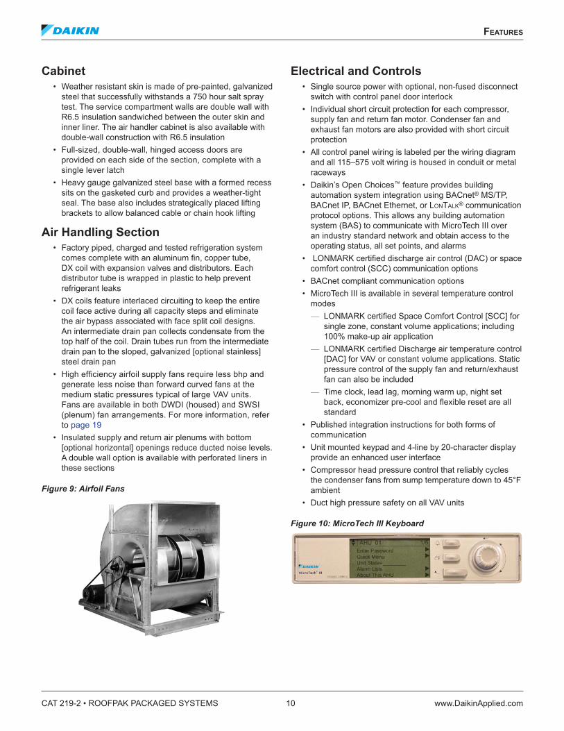
• High efficiency airfoil supply fans require less bhp and generate less noise than forward curved fans at the medium static pressures typical of large VAV units. Fans are available in both DWDI (housed) and SWSI (plenum) fan arrangements. For more information, refer to page 19
• Insulated supply and return air plenums with bottom [optional horizontal] openings reduce ducted noise levels. A double wall option is available with perforated liners in these sections
Figure 9: Airfoil Fans
Electrical and Controls• Single source power with optional, non-fused disconnect
switch with control panel door interlock• Individual short circuit protection for each compressor,
supply fan and return fan motor. Condenser fan and exhaust fan motors are also provided with short circuit protection
• All control panel wiring is labeled per the wiring diagram and all 115–575 volt wiring is housed in conduit or metal raceways
• Daikin’s Open Choices™ feature provides building automation system integration using BACnet® MS/TP, BACnet IP, BACnet Ethernet, or LonTaLk® communication protocol options. This allows any building automation system (BAS) to communicate with MicroTech III over an industry standard network and obtain access to the operating status, all set points, and alarms
• LONMARK certified discharge air control (DAC) or space comfort control (SCC) communication options
• BACnet compliant communication options• MicroTech III is available in several temperature control
modes — LONMARK certified Space Comfort Control [SCC] for single zone, constant volume applications; including 100% make-up air application
— LONMARK certified Discharge air temperature control [DAC] for VAV or constant volume applications. Static pressure control of the supply fan and return/exhaust fan can also be included
— Time clock, lead lag, morning warm up, night set back, economizer pre-cool and flexible reset are all standard
• Published integration instructions for both forms of communication
• Unit mounted keypad and 4-line by 20-character display provide an enhanced user interface
• Compressor head pressure control that reliably cycles the condenser fans from sump temperature down to 45°F ambient
• Duct high pressure safety on all VAV units
Figure 10: MicroTech III Keyboard
faCTory InsTalled and WIred opTIons
www.DaikinApplied.com 11 CAT 219-2 • ROOFPAK PACKAGED SYSTEMS
faCTory InsTalled and WIred opTIons
The RPE and RDE contain the same air handler construction and controls as the RPS and RDT units. For complete detail refer to RPS Catalog 214 and RDT Catalog 217. For a copy of these catalogs, contact your local Daikin representative or visit DaikinApplied.com.
Condensing Section• Compressor spring isolation with suction and discharge
line vibration absorbers• Extra compressor unloaders that provide 6 stages (size
76–100) or 8 stages (size 110–150) of capacity control• Compressor part winding start to reduce inrush current• Replaceable core filter driers• Hot gas bypass on one or both refrigerant circuits• Electric sump heater that helps prevent the sump from
freezing in cold weather. Heat tape is also included for the sump drain and supply water lines
• 1.5 kW electric unit heater and ambient ON-OFF thermostat for the service compartment
Air Handling Section• Multiple fan and coil options optimize reliability, efficiency,
sound performance and first cost for varying cfm per ton operation. Units can be selected for make-up air applications
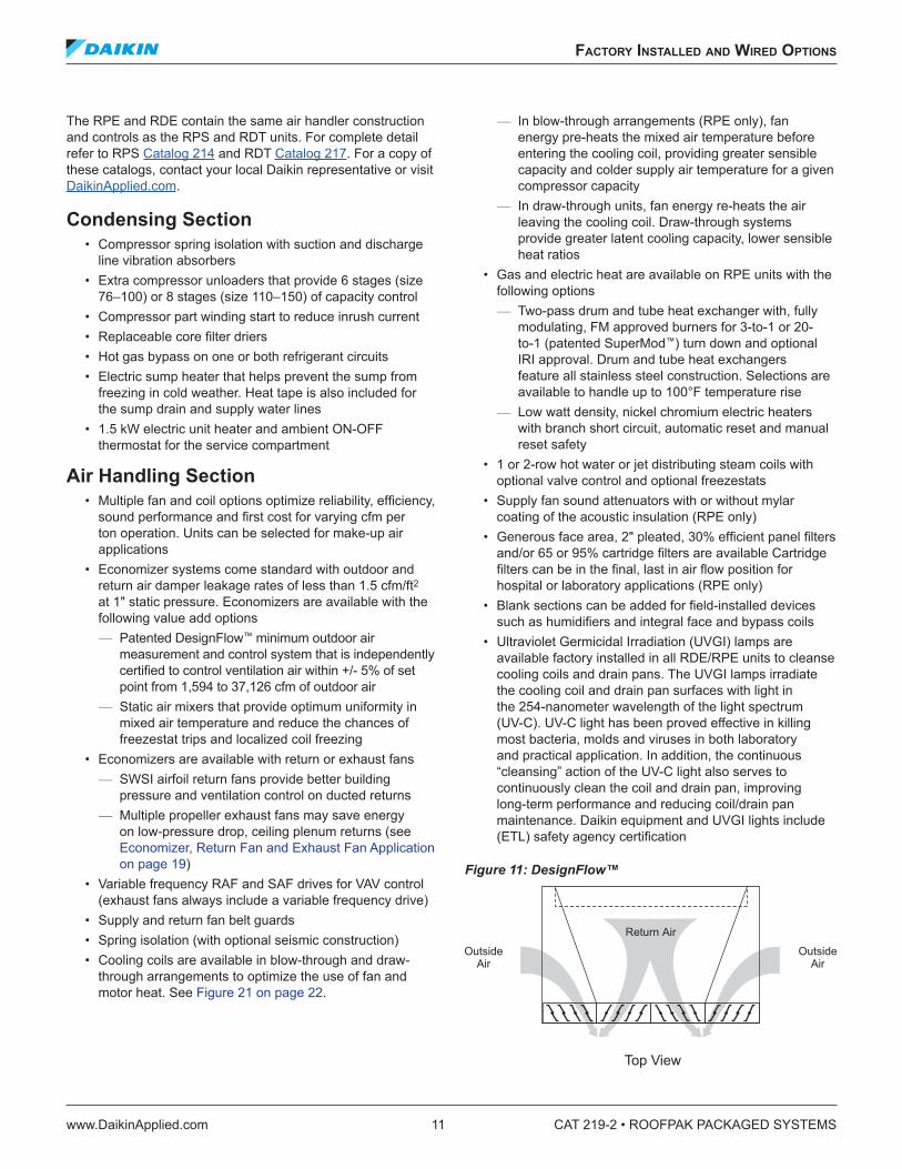
• Economizer systems come standard with outdoor and return air damper leakage rates of less than 1.5 cfm/ft2 at 1" static pressure. Economizers are available with the following value add options
— Patented DesignFlow™ minimum outdoor air measurement and control system that is independently certified to control ventilation air within +/- 5% of set point from 1,594 to 37,126 cfm of outdoor air
— Static air mixers that provide optimum uniformity in mixed air temperature and reduce the chances of freezestat trips and localized coil freezing
• Economizers are available with return or exhaust fans — SWSI airfoil return fans provide better building pressure and ventilation control on ducted returns
— Multiple propeller exhaust fans may save energy on low-pressure drop, ceiling plenum returns (see Economizer, Return Fan and Exhaust Fan Application on page 19)
• Variable frequency RAF and SAF drives for VAV control (exhaust fans always include a variable frequency drive)
• Supply and return fan belt guards• Spring isolation (with optional seismic construction)• Cooling coils are available in blow-through and draw-
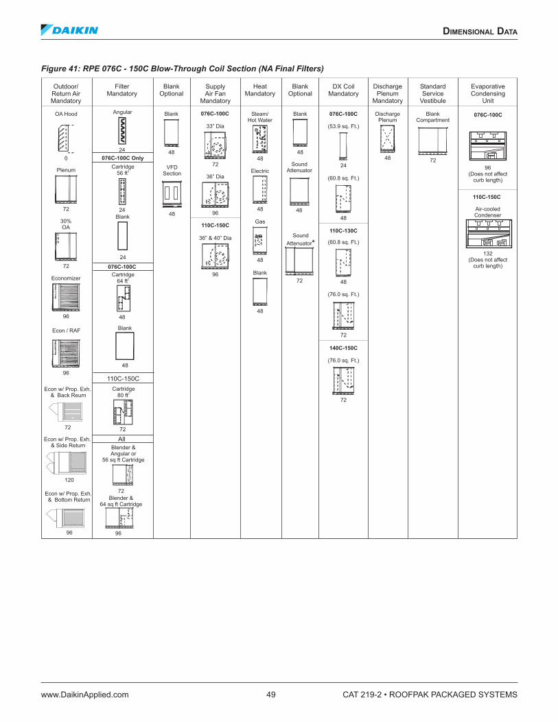
through arrangements to optimize the use of fan and motor heat. See Figure 21 on page 22.
— In blow-through arrangements (RPE only), fan energy pre-heats the mixed air temperature before entering the cooling coil, providing greater sensible capacity and colder supply air temperature for a given compressor capacity
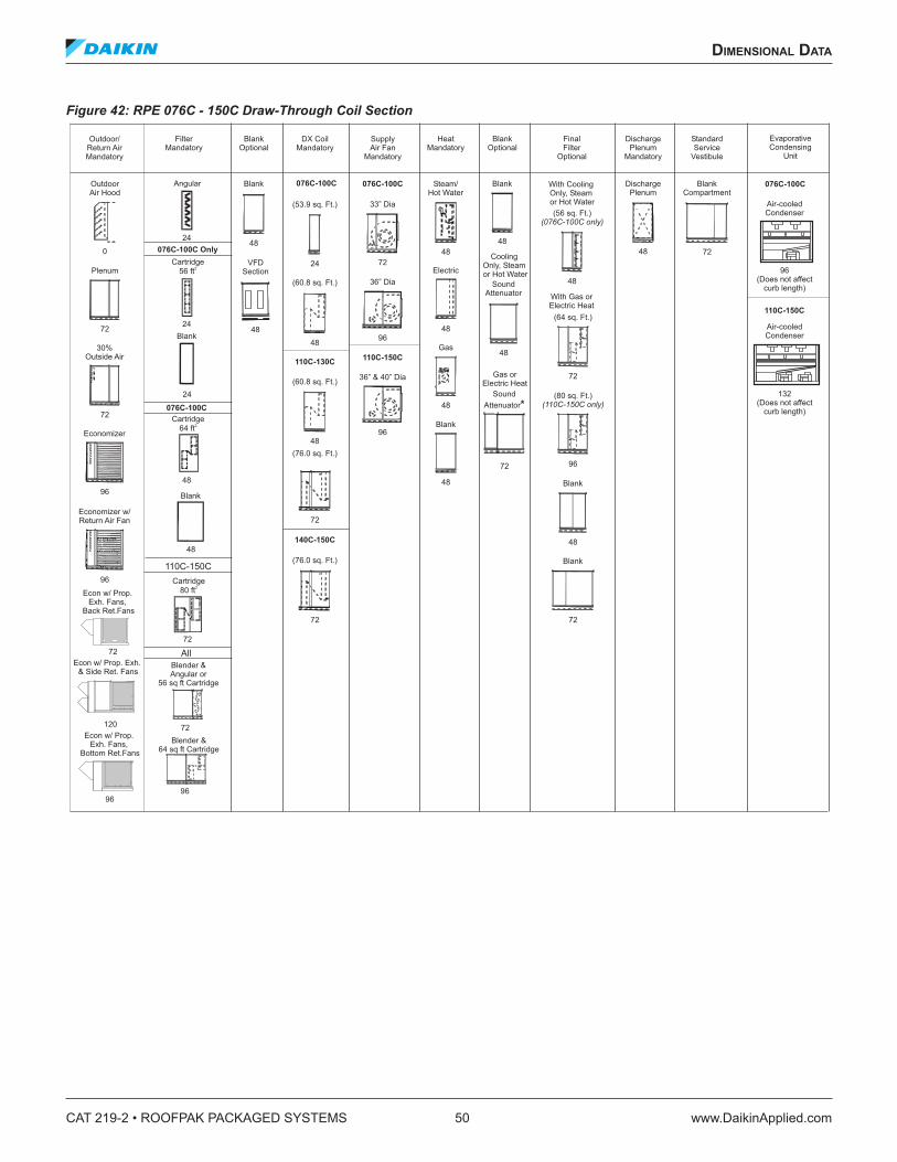
— In draw-through units, fan energy re-heats the air leaving the cooling coil. Draw-through systems provide greater latent cooling capacity, lower sensible heat ratios
• Gas and electric heat are available on RPE units with the following options
— Two-pass drum and tube heat exchanger with, fully modulating, FM approved burners for 3-to-1 or 20- to-1 (patented SuperMod™) turn down and optional IRI approval. Drum and tube heat exchangers feature all stainless steel construction. Selections are available to handle up to 100°F temperature rise
— Low watt density, nickel chromium electric heaters with branch short circuit, automatic reset and manual reset safety
• 1 or 2-row hot water or jet distributing steam coils with optional valve control and optional freezestats
• Supply fan sound attenuators with or without mylar coating of the acoustic insulation (RPE only)
• Generous face area, 2" pleated, 30% efficient panel filters and/or 65 or 95% cartridge filters are available Cartridge filters can be in the final, last in air flow position for hospital or laboratory applications (RPE only)
• Blank sections can be added for field-installed devices such as humidifiers and integral face and bypass coils
• Ultraviolet Germicidal Irradiation (UVGI) lamps are available factory installed in all RDE/RPE units to cleanse cooling coils and drain pans. The UVGI lamps irradiate the cooling coil and drain pan surfaces with light in the 254-nanometer wavelength of the light spectrum (UV-C). UV-C light has been proved effective in killing most bacteria, molds and viruses in both laboratory and practical application. In addition, the continuous “cleansing” action of the UV-C light also serves to continuously clean the coil and drain pan, improving long-term performance and reducing coil/drain pan maintenance. Daikin equipment and UVGI lights include (ETL) safety agency certification
CAT 219-2 • ROOFPAK PACKAGED SYSTEMS 12 www.DaikinApplied.com
faCTory InsTalled and WIred opTIons
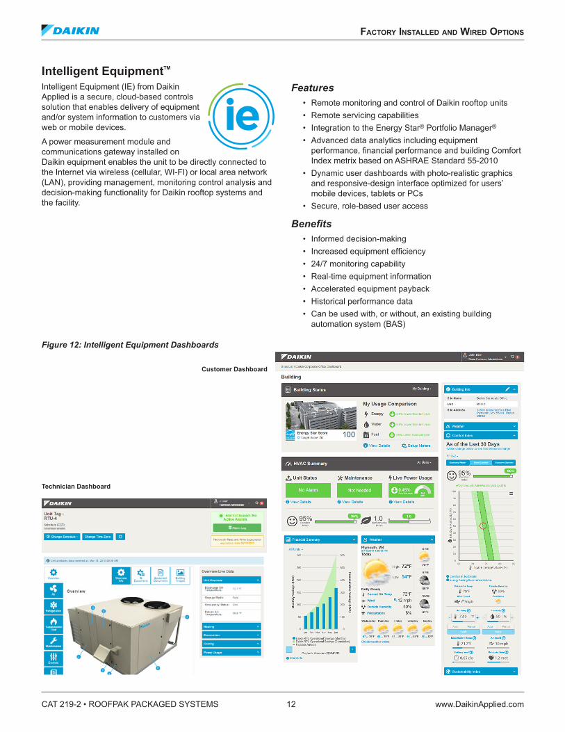
Intelligent Equipment™
Intelligent Equipment (IE) from Daikin Applied is a secure, cloud-based controls solution that enables delivery of equipment and/or system information to customers via web or mobile devices.
A power measurement module and communications gateway installed on Daikin equipment enables the unit to be directly connected to the Internet via wireless (cellular, WI-FI) or local area network (LAN), providing management, monitoring control analysis and decision-making functionality for Daikin rooftop systems and the facility.
Features• Remote monitoring and control of Daikin rooftop units• Remote servicing capabilities• Integration to the Energy Star® Portfolio Manager®
• Advanced data analytics including equipment performance, financial performance and building Comfort Index metrix based on ASHRAE Standard 55-2010
• Dynamic user dashboards with photo-realistic graphics and responsive-design interface optimized for users’ mobile devices, tablets or PCs
• Secure, role-based user access
Benefits• Informed decision-making• Increased equipment efficiency• 24/7 monitoring capability• Real-time equipment information• Accelerated equipment payback• Historical performance data• Can be used with, or without, an existing building
automation system (BAS)
Figure 12: Intelligent Equipment Dashboards
Customer Dashboard
Technician Dashboard
faCTory InsTalled and WIred opTIons
www.DaikinApplied.com 13 CAT 219-2 • ROOFPAK PACKAGED SYSTEMS
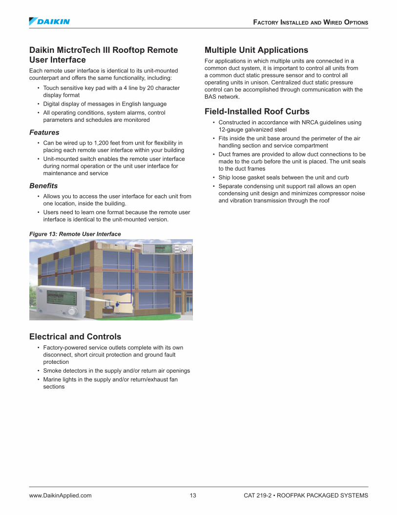
Daikin MictroTech III Rooftop Remote User InterfaceEach remote user interface is identical to its unit-mounted counterpart and offers the same functionality, including:
• Touch sensitive key pad with a 4 line by 20 character display format
• Digital display of messages in English language• All operating conditions, system alarms, control
parameters and schedules are monitored
Features• Can be wired up to 1,200 feet from unit for flexibility in
placing each remote user interface within your building• Unit-mounted switch enables the remote user interface
during normal operation or the unit user interface for maintenance and service
Benefits• Allows you to access the user interface for each unit from
one location, inside the building.• Users need to learn one format because the remote user
interface is identical to the unit-mounted version.
Figure 13: Remote User Interface
Electrical and Controls• Factory-powered service outlets complete with its own
disconnect, short circuit protection and ground fault protection
• Smoke detectors in the supply and/or return air openings• Marine lights in the supply and/or return/exhaust fan
sections
Multiple Unit ApplicationsFor applications in which multiple units are connected in a common duct system, it is important to control all units from a common duct static pressure sensor and to control all operating units in unison. Centralized duct static pressure control can be accomplished through communication with the BAS network.
Field-Installed Roof Curbs• Constructed in accordance with NRCA guidelines using
12-gauge galvanized steel• Fits inside the unit base around the perimeter of the air
handling section and service compartment• Duct frames are provided to allow duct connections to be
made to the curb before the unit is placed. The unit seals to the duct frames
• Ship loose gasket seals between the unit and curb• Separate condensing unit support rail allows an open
condensing unit design and minimizes compressor noise and vibration transmission through the roof
CAT 219-2 • ROOFPAK PACKAGED SYSTEMS 14 www.DaikinApplied.com
faCTory InsTalled and WIred opTIons
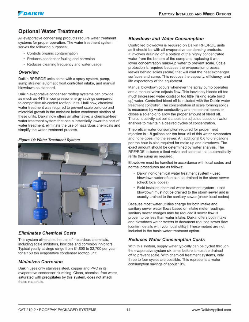
Optional Water TreatmentAll evaporative condensing products require water treatment systems for proper operation. The water treatment system serves the following purposes:
• Controls organic contamination• Reduces condenser fouling and corrosion• Reduces cleaning frequency and water usage
OverviewDaikin RPE/RDE units come with a spray system, pump, sump strainer, automatic float controlled intake, and manual blowdown as standard.
Daikin evaporative condenser rooftop systems can provide as much as 44% in compressor energy savings compared to competitive air-cooled rooftop units. Until now, chemical water treatment was required to prevent scale build-up and microbial growth in the moisture laden condenser section of these units. Daikin now offers an alternative: a chemical-free water treatment system that can substantially lower the cost of water treatment, eliminate the use of hazardous chemicals and simplify the water treatment process.
Figure 14: Water Treatment System
Eliminates Chemical CostsThis system eliminates the use of hazardous chemicals, including scale inhibitors, biocides and corrosion inhibitors. Typical yearly savings range from $1,800 to $2,700 per year for a 150 ton evaporative condenser rooftop unit.
Minimizes CorrosionDaikin uses only stainless steel, copper and PVC in its evaporative condenser plumbing. Clean, chemical-free water, saturated with precipitates by this system, does not attack these materials.
Blowdown and Water ConsumptionControlled blowdown is required on Daikin RPE/RDE units as it should be with all evaporative condensing products. It involves draining off a portion of the highly concentrated water from the bottom of the sump and replacing it with lower concentration make-up water to prevent scale. Scale protection is required because the evaporation process leaves behind solids (scale) that will coat the heat exchanger surfaces and sump. This reduces the capacity, efficiency, and life expectancy of the equipment.
Manual blowdown occurs whenever the spray pump operates and a manual valve adjusts flow. This inevitably bleeds off too much [increased water costs] or too little [risking scale build up] water. Controlled bleed off is included with the Daikin water treatment controller. The concentration of scale forming solids is measured by water conductivity and the control opens or closes a solenoid to allow the proper amount of bleed off. The conductivity set point should be adjusted based on water analysis to maintain a desired cycles of concentration.
Theoretical water consumption required for proper heat rejection is 1.8 gallons per ton hour. All of this water evaporates and none goes into the sewer. An additional 0.6 to 0.9 gallons per ton hour is also required for make up and blowdown. The exact amount should be determined by water analysis. The RPE/RDE includes a float valve and solenoid that automatically refills the sump as required.
Blowdown must be handled in accordance with local codes and normal procedures are as follows:
• Daikin non-chemical water treatment system - used blowdown water often can be drained to the storm sewer (check local codes)
• Field installed chemical water treatment system - used blowdown must not be drained to the storm sewer and is usually drained to the sanitary sewer (check local codes)
Because most water utilities charge for both intake and sanitary sewer water flows based on intake meter readings, sanitary sewer charges may be reduced if sewer flow is proven to be less than water intake. Daikin offers both intake and blowdown water meters to document reduced sewer flow [confirm details with your local utility]. These meters are not included in the basic water treatment option.
Reduces Water Consumption CostsWith this system, supply water typically can be cycled through the evaporative system six times before it must be drained off to prevent scale. With chemical treatment systems, only three to four cycles are possible. This represents a water consumption savings of about 10%.
faCTory InsTalled and WIred opTIons
www.DaikinApplied.com 15 CAT 219-2 • ROOFPAK PACKAGED SYSTEMS
A Cleaner EnvironmentDaikin evaporative condenser rooftop units equipped with a chemical-free water treatment system contribute to a cleaner environment by reducing energy usage and by eliminating the introduction of hazardous chemicals into the waste stream.
Reduces Sanitary Sewer CostsSavings in sanitary sewer costs can be even more dramatic. That’s because this system requires no sanitary sewer usage— all condenser water, including blow-down, usually can be drained to the storm sewer or used for irrigation (check local codes). This represents a 10 to 15% water cost savings if sewer flow is measured (i.e., credit is given for the water that evaporates during the cooling process) and even more if it is not.
Chemical-Free BenefitsAs a scale inhibitor, the Daikin chemical-free system uses pulsed electromagnetic fields to neutralize the charge on particles suspended in water, causing them to attract to each other rather than to form scale on plumbing and heat transfer surfaces. The particles grow, encapsulate any micro- organisms, and precipitate out of solution as a powder. A cyclone separator removes the powder from the system during the blow-down process. For microbial control, the system uses pulsed electromagnetic fields to attack the cell walls of any microorganisms that are not encapsulated. As a result, TBC is typically 75% less than with chemical treatment systems. In fact, total bacterial count (TBC) is so low that biofilms are normally prevented.
Easy MaintenanceThe Daikin chemical-free water treatment system has no moving parts and is easy to maintain. Inspection and monitoring are only required once or twice per quarter, as follows:
• Check the water conductivity (and clean conductivity sensor if necessary)
• Check total bacteria count (TBC)• Inspect general operation and controller settings
LEED Point AvailableChemical-free water treatment systems qualify for a LEED point under the “Innovation” heading, per a Credit Interpretation Request posted on the USGBC website.
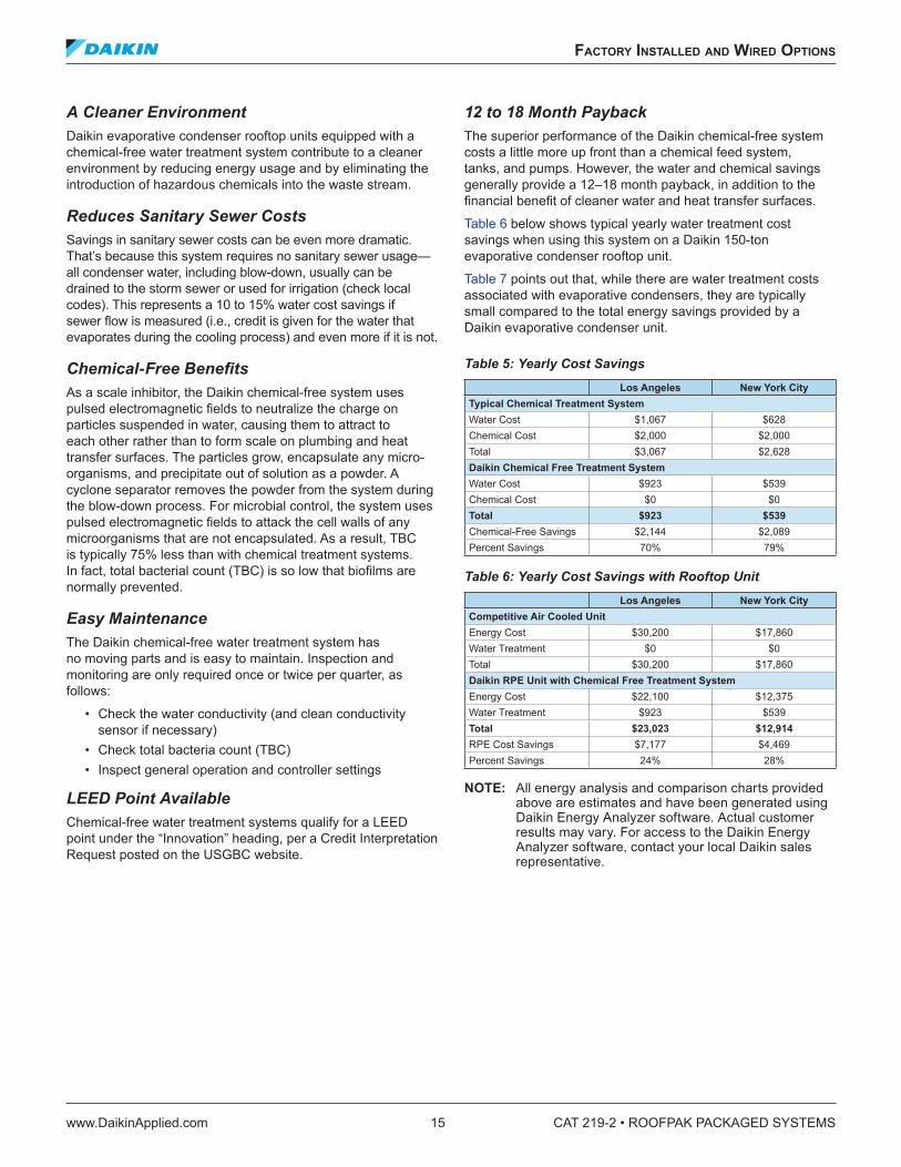
12 to 18 Month PaybackThe superior performance of the Daikin chemical-free system costs a little more up front than a chemical feed system, tanks, and pumps. However, the water and chemical savings generally provide a 12–18 month payback, in addition to the financial benefit of cleaner water and heat transfer surfaces.
Table 6 below shows typical yearly water treatment cost savings when using this system on a Daikin 150-ton evaporative condenser rooftop unit.
Table 7 points out that, while there are water treatment costs associated with evaporative condensers, they are typically small compared to the total energy savings provided by a Daikin evaporative condenser unit.
Table 5: Yearly Cost SavingsLos Angeles New York City
Table 6: Yearly Cost Savings with Rooftop UnitLos Angeles New York City
Competitive Air Cooled UnitEnergy Cost $30,200 $17,860Water Treatment $0 $0Total $30,200 $17,860Daikin RPE Unit with Chemical Free Treatment SystemEnergy Cost $22,100 $12,375Water Treatment $923 $539Total $23,023 $12,914RPE Cost Savings $7,177 $4,469Percent Savings 24% 28%
NOTE: All energy analysis and comparison charts provided above are estimates and have been generated using Daikin Energy Analyzer software. Actual customer results may vary. For access to the Daikin Energy Analyzer software, contact your local Daikin sales representative.
CAT 219-2 • ROOFPAK PACKAGED SYSTEMS 16 www.DaikinApplied.com
faCTory InsTalled and WIred opTIons
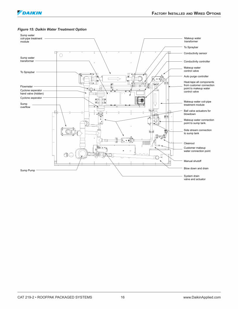
Figure 15: Daikin Water Treatment Option
Makeup water control valve
Manual shutoff
Heat-tape all components from customer connection point to makeup water control valve
Makeup water coil-pipe treatment module
Makeup water connection point to sump tank.
Side stream connection to sump tank
Cleanout
Customer makeup water connection point
Blow down and drain
Conductivity controller
Conductivity sensor
Auto purge controller
Makeup water transformer
System drain valve and actuator
Sump Pump
Sump overflow
Cyclone seperator
Cyclone seperator hand valve (hidden)
Flowmeter
Ball valve actuators for blowdown
Sump water coil-pipe treatment module
To Spraybar
Sump water transformer
To Spraybar
applICaTIon ConsIderaTIons
www.DaikinApplied.com 17 CAT 219-2 • ROOFPAK PACKAGED SYSTEMS
applICaTIon ConsIderaTIons
The RPE and RDE require many of the same application considerations as Daikin RPS and RDT units. More detail is provided in RPS Catalog 214 and RDT Catalog 217. For a copy of these catalogs, contact your local Daikin representative or visit DaikinApplied.com
General• Intended for normal HVAC use. Consult factory if
cataloged operating range is exceeded, such as make up air. Compressor cooling below 45°F is not allowed
• Rig the unit in accordance with the instructions provided in the Installation Manual IM 791. Split units are available to reduce rigging weight and may be required if the total length exceeds 52 ft. For a copy of IM 791, contact your local Daikin representative or visit DaikinApplied.com
• Fire dampers may be required by code. They are not included
• Qualified Start-up of the unit in accordance with the IM 791 is required
• Clean off any road chemicals, such as winter salt, when the unit is received
• Proper water treatment must be provided before unit start-up
Location and Curb/Rail Support• The structural engineer must verify that sufficient roof
strength is provided• Maximum unit pitch is 1/16 in. per foot. Curbs or
supporting rails must be rigidly supported along the entire length of the unit to prevent deflection that results in door interference
• Gaskets must be installed between the curb and the unit, per IM 791
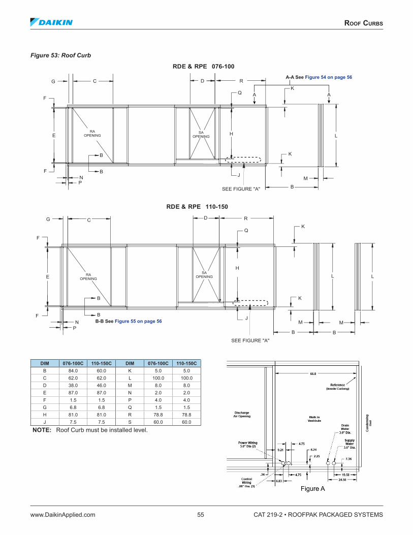
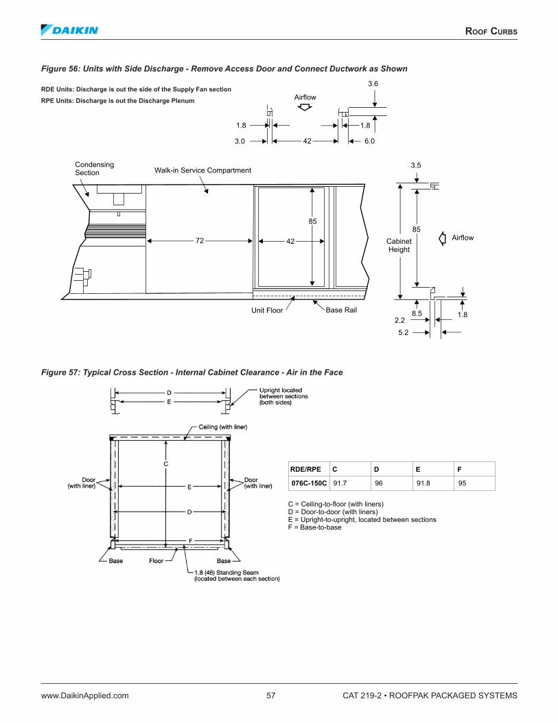
• Curbs must be installed per NRCA guidelines See Roof Curbs on page 55
• Avoid locating the unit near any heat source, exhaust, smoke stack, or any source of air-borne particles or chemicals
• Local codes must be followed regarding fastening the unit to the curb/rail and the curb/rail to the building. This is especially critical in higher risk, hurricane or seismic zones
• Refer to the Acoustics on page 18 to avoid noise and vibration problems
• Daikin curbs include supply and return opening support frames and perimeter channels that seal to the unit as it is placed on the curb. Therefore, duct connections can be made to the curb before the unit is placed
Filters• Filters should be replaced on a regular basis to avoid
excessive pressure drop increases, especially on high efficiency cartridge filters
• Fan selection must consider dirty filter losses. Using a filter pressure drop midway between clean and dirty values is recommended unless maintaining minimum cfm is critical
• Daikin RPE units offer last in air stream “final” filters. They require special consideration
• The Daikin design uses full double-wall construction down stream of the final filters
• Cooling coils must be in the draw-through position.• Final filters down stream of gas and electric heaters must
be rated for 500°F temperatures. Maintenance personnel must use properly-rated replacement filters
CAT 219-2 • ROOFPAK PACKAGED SYSTEMS 18 www.DaikinApplied.com
applICaTIon ConsIderaTIons
AcousticsDucted and radiated sound power ratings are available from your local Daikin sales representative. The designer is responsible for addressing these sound levels. The following guidelines will help to achieve the desired sound levels in the occupied space.
• Locate the unit as far away from sound sensitive areas as possible. Refer to the Location and Curb/Rail Support on page 17
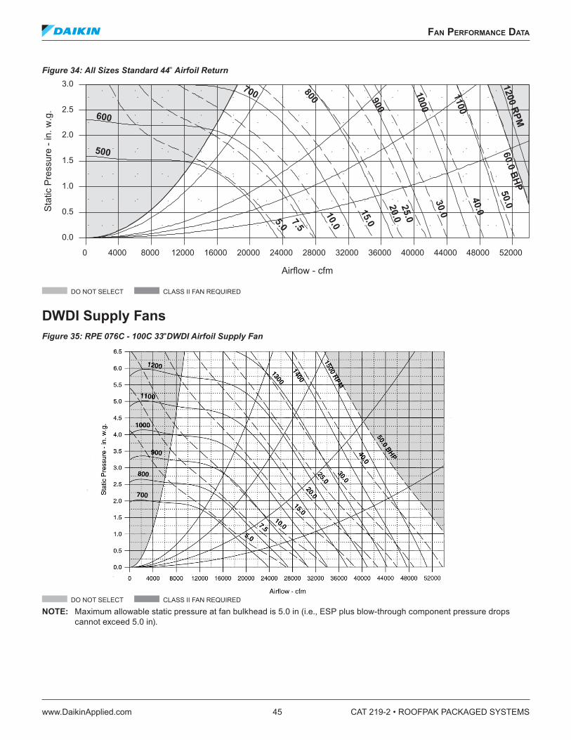
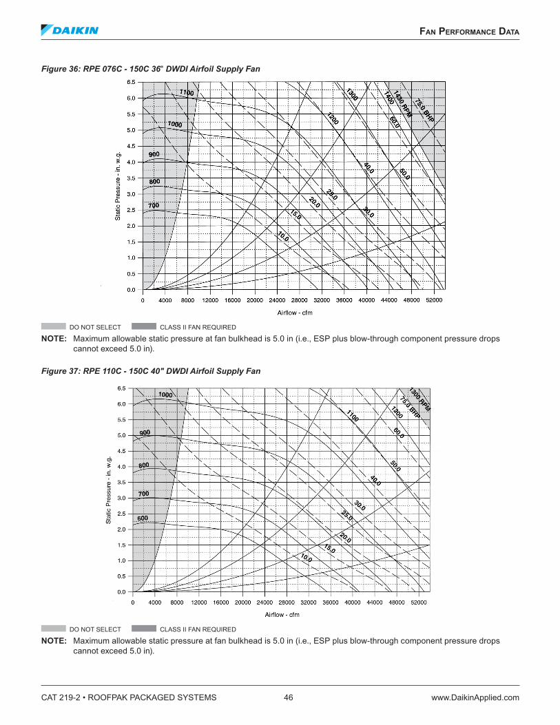
• Minimize supply and return fan TSP and select the fan as close to peak efficiency as possible. Avoid the “do not select” areas on the fan curve. Daikin offers several different fans per model size to allow for various design conditions. Refer to Fan Performance Data on page 44
Three different sound paths from the unit to occupants and/or neighbors must be considered:
1. Radiated path
• Use a concrete deck or pad when the unit must be located over sound sensitive areas. If this isn’t possible, provide extra acoustical insulation under the condensing unit
• Only the supply and return ducts, and the essential plumbing and electrical connections should penetrate the acoustical insulation or roofing below the unit. The outside perimeter of the ducts must be sealed after they are installed
• If a built-up roof with metal decking is used, then the area inside the curb perimeter requires special attention:
— Provide an inverted 6" channel around the inside perimeter of the curb and seal to the curb
— Acoustical insulation must be installed above the decking and the 6" channel
2. Vibration path
• Locate the unit’s center of gravity close to a main support beam to minimize roof deflection and vibration transmission into the building
• Daikin offers 2" deflection, supply and return fan spring isolation or rubber in shear isolators. The rubber in shear isolators should only be used when vibration isolation is clearly not required in the rooftop, such as when the unit is mounted on spring isolated curbs, spring isolated rails or the ground
• Daikin offers compressor spring isolation, including the necessary refrigerant line vibration eliminators
• Internal spring isolation options may be insufficient for some applications. Spring isolation of the entire unit may be required
3. Air-borne path through the supply and return openings
• Use 2003 ASHRAE Fundamentals Chapter 43 to help reduce ducted noise and minimize duct turbulence. Maintain straight ducts to and from the unit and avoid abrupt changes in duct size and direction. Avoid turns opposed to the fan wheel rotation. If 90° elbows are required, use turning vanes
• Use as much insulated return duct as possible and include at least one elbow and 15' of length. Maximum recommended velocities are 1000–1200 fpm
• Allow for duct break out and use oval or round duct whenever possible
• Insulate the first 20' of supply duct. The first 20' of rectangular duct should be routed over non-sensitive areas and avoid large aspect ratios. Maximum recommended velocities are 1800–2000 fpm
• Daikin offers factory-installed discharge plenums with optional perforated liners. The plenum provides several dB of attenuation and discharges the air at a more uniform, relatively low velocity. Ducted supply noise can be further reduced by adding optional sound attenuators between the supply fan and the unit discharge
• Route the return air path through the length of the curb to add distance between the unit return opening and the building return opening
applICaTIon ConsIderaTIons
www.DaikinApplied.com 19 CAT 219-2 • ROOFPAK PACKAGED SYSTEMS
Economizer, Return Fan and Exhaust Fan ApplicationRooftop economizer applications usually require return or exhaust fans to properly control building pressure and maintain minimum ventilation. Daikin offers both exhaust and return fan capability. They are not generally interchangeable for a given design. In general:
• Return air fans (RAF) should be used on ducted return systems (return ESP exceeds 0.4–0.5 in.)
• Properly selected propeller exhaust air fans (EAF) can successfully operate and save energy on open return systems (return ESP is less than 0.4–0.5 in.)
• Supply air fan (SAF) selection depends on whether a return or exhaust fan is used
— RAF system-SAF handles only the supply ESP at design
— EAF system-SAF handles both the supply and return ESP at design (EAF is OFF)
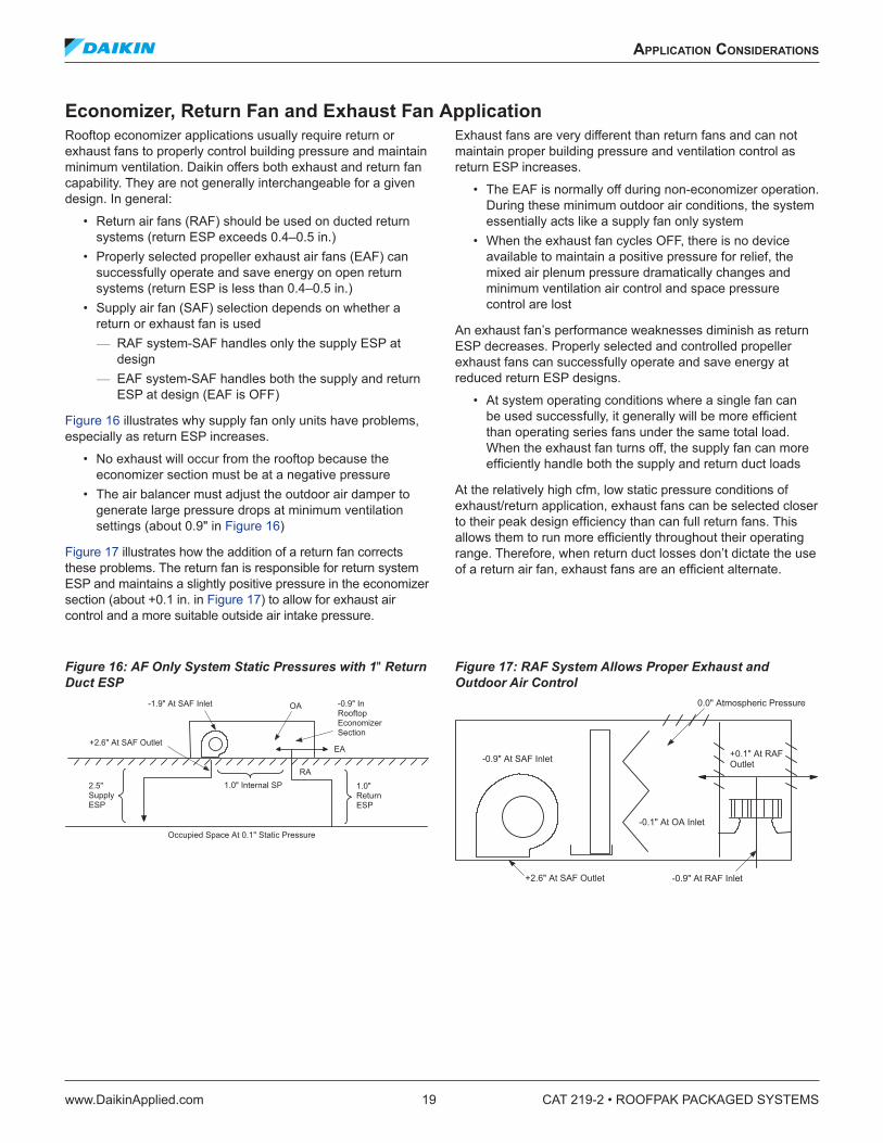
Figure 16 illustrates why supply fan only units have problems, especially as return ESP increases.
• No exhaust will occur from the rooftop because the economizer section must be at a negative pressure
• The air balancer must adjust the outdoor air damper to generate large pressure drops at minimum ventilation settings (about 0.9" in Figure 16)
Figure 17 illustrates how the addition of a return fan corrects these problems. The return fan is responsible for return system ESP and maintains a slightly positive pressure in the economizer section (about +0.1 in. in Figure 17) to allow for exhaust air control and a more suitable outside air intake pressure.
Exhaust fans are very different than return fans and can not maintain proper building pressure and ventilation control as return ESP increases.
• The EAF is normally off during non-economizer operation. During these minimum outdoor air conditions, the system essentially acts like a supply fan only system
• When the exhaust fan cycles OFF, there is no device available to maintain a positive pressure for relief, the mixed air plenum pressure dramatically changes and minimum ventilation air control and space pressure control are lost
An exhaust fan’s performance weaknesses diminish as return ESP decreases. Properly selected and controlled propeller exhaust fans can successfully operate and save energy at reduced return ESP designs.
• At system operating conditions where a single fan can be used successfully, it generally will be more efficient than operating series fans under the same total load. When the exhaust fan turns off, the supply fan can more efficiently handle both the supply and return duct loads
At the relatively high cfm, low static pressure conditions of exhaust/return application, exhaust fans can be selected closer to their peak design efficiency than can full return fans. This allows them to run more efficiently throughout their operating range. Therefore, when return duct losses don’t dictate the use of a return air fan, exhaust fans are an efficient alternate.
Figure 16: AF Only System Static Pressures with 1" Return Duct ESP
Figure 17: RAF System Allows Proper Exhaust and Outdoor Air Control
CAT 219-2 • ROOFPAK PACKAGED SYSTEMS 20 www.DaikinApplied.com
applICaTIon ConsIderaTIons
Variable Air Volume (VAV)Daikin Rooftop VAV options include everything required to provide the full advantages of true shut-off VAV. Bypass VAV systems do not offer any fan energy savings at light load.
• Variable Frequency Drives for all indoor fans maximize part load fan efficiency and minimize fan sound generation
• Indoor fan volume control based on supply static pressure and building pressure
• Up to 2 supply duct sensors to properly respond to building diversity (such as east-west variation)
• Constant discharge temperature control. Shut-off VAV offers the following advantages
• Reduces first cost and energy due to building diversity• Reduces indoor fan energy requirements at light load• Provides the opportunity for efficient multiple zone control
from a single unit and to match changing occupancy demands
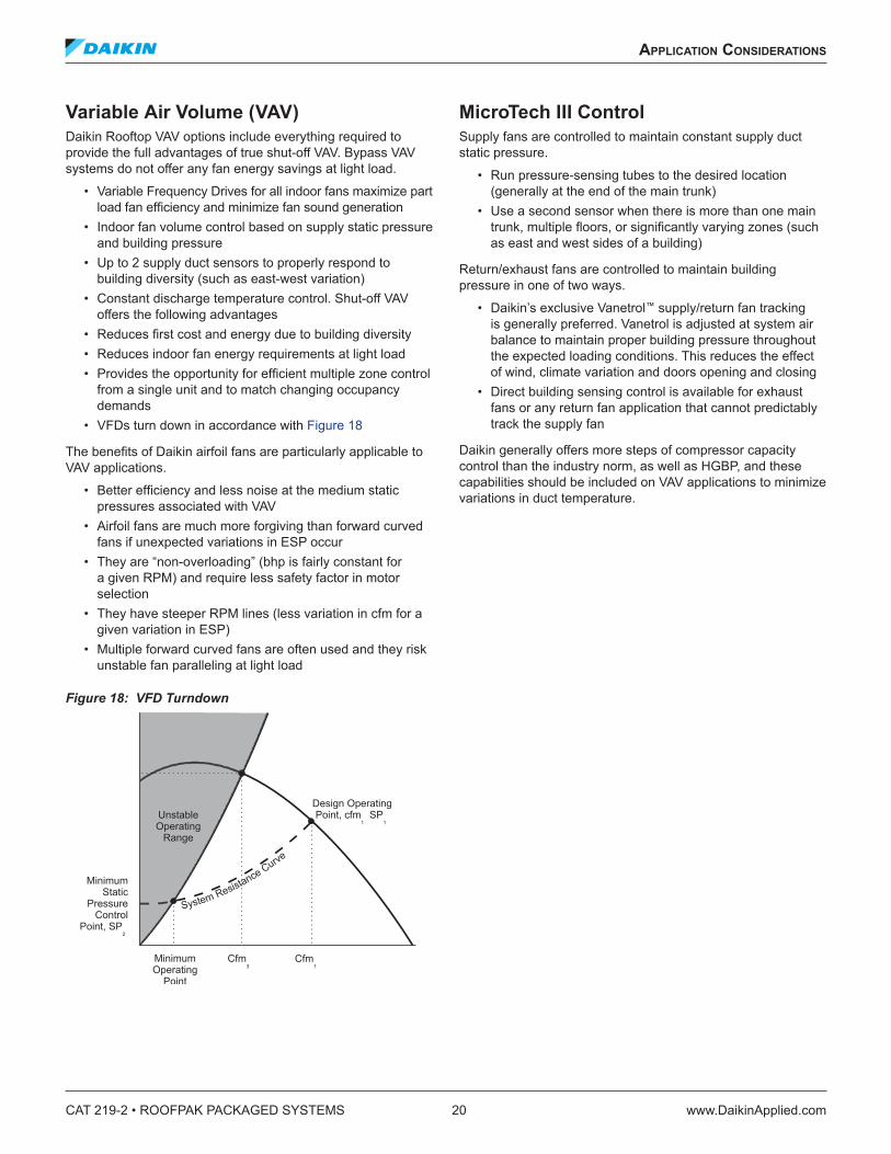
• VFDs turn down in accordance with Figure 18
The benefits of Daikin airfoil fans are particularly applicable to VAV applications.
• Better efficiency and less noise at the medium static pressures associated with VAV
• Airfoil fans are much more forgiving than forward curved fans if unexpected variations in ESP occur
• They are “non-overloading” (bhp is fairly constant for a given RPM) and require less safety factor in motor selection
• They have steeper RPM lines (less variation in cfm for a given variation in ESP)
• Multiple forward curved fans are often used and they risk unstable fan paralleling at light load
Figure 18: VFD Turndown
MicroTech III ControlSupply fans are controlled to maintain constant supply duct static pressure.
• Run pressure-sensing tubes to the desired location (generally at the end of the main trunk)
• Use a second sensor when there is more than one main trunk, multiple floors, or significantly varying zones (such as east and west sides of a building)
Return/exhaust fans are controlled to maintain building pressure in one of two ways.
• Daikin’s exclusive Vanetrol™ supply/return fan tracking is generally preferred. Vanetrol is adjusted at system air balance to maintain proper building pressure throughout the expected loading conditions. This reduces the effect of wind, climate variation and doors opening and closing
• Direct building sensing control is available for exhaust fans or any return fan application that cannot predictably track the supply fan
Daikin generally offers more steps of compressor capacity control than the industry norm, as well as HGBP, and these capabilities should be included on VAV applications to minimize variations in duct temperature.
applICaTIon ConsIderaTIons
www.DaikinApplied.com 21 CAT 219-2 • ROOFPAK PACKAGED SYSTEMS
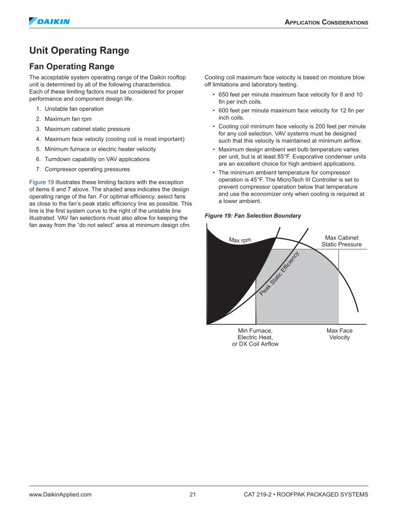
Unit Operating RangeFan Operating RangeThe acceptable system operating range of the Daikin rooftop unit is determined by all of the following characteristics. Each of these limiting factors must be considered for proper performance and component design life.
1. Unstable fan operation
2. Maximum fan rpm
3. Maximum cabinet static pressure
4. Maximum face velocity (cooling coil is most important)
5. Minimum furnace or electric heater velocity
6. Turndown capability on VAV applications
7. Compressor operating pressures
Figure 19 illustrates these limiting factors with the exception of items 6 and 7 above. The shaded area indicates the design operating range of the fan. For optimal efficiency, select fans as close to the fan’s peak static efficiency line as possible. This line is the first system curve to the right of the unstable line illustrated. VAV fan selections must also allow for keeping the fan away from the “do not select” area at minimum design cfm.
Cooling coil maximum face velocity is based on moisture blow off limitations and laboratory testing.
• 650 feet per minute maximum face velocity for 8 and 10 fin per inch coils.
• 600 feet per minute maximum face velocity for 12 fin per inch coils.
• Cooling coil minimum face velocity is 200 feet per minute for any coil selection. VAV systems must be designed such that this velocity is maintained at minimum airflow.
• Maximum design ambient wet bulb temperature varies per unit, but is at least 85°F. Evaporative condenser units are an excellent choice for high ambient applications.
• The minimum ambient temperature for compressor operation is 45°F. The MicroTech III Controller is set to prevent compressor operation below that temperature and use the economizer only when cooling is required at a lower ambient.
Figure 19: Fan Selection Boundary
Do Not Select
CAT 219-2 • ROOFPAK PACKAGED SYSTEMS 22 www.DaikinApplied.com
applICaTIon ConsIderaTIons
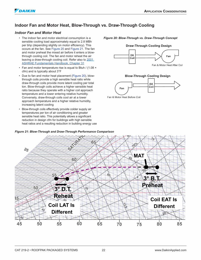
Indoor Fan and Motor Heat, Blow-Through vs . Draw-Through CoolingIndoor Fan and Motor Heat
• The indoor fan and motor electrical consumption is a sensible cooling load approximately equal to 2.8 MBh per bhp (depending slightly on motor efficiency). This occurs at the fan. See Figure 20 and Figure 21. The fan and motor preheat the mixed air before it enters a blow-through cooling coil. The fan and motor reheat the air leaving a draw-through cooling coil. Refer also to 2001 ASHRAE Fundamentals Handbook, Chapter 31
• Fan and motor temperature rise is equal to Btuh / (1.08 × cfm) and is typically about 3°F
• Due to fan and motor heat placement (Figure 20), blow-through coils provide a high sensible heat ratio while draw-through coils provide more latent cooling per total ton. Blow-through coils achieve a higher sensible heat ratio because they operate with a higher coil approach temperature and a lower entering relative humidity. Conversely, draw-through coils cool air at a lower approach temperature and a higher relative humidity, increasing latent cooling
• Blow-through coils effectively provide colder supply air temperatures per ton of air conditioning and greater sensible heat ratio. This potentially allows a significant reduction in design cfm for buildings with high sensible heat ratios and a resulting reduction in building energy use
Figure 20: Blow-Through vs. Draw-Through Concept
Figure 21: Blow-Through and Draw-Through Performance Comparison
www.DaikinApplied.com 23 CAT 219-2 • ROOFPAK PACKAGED SYSTEMS
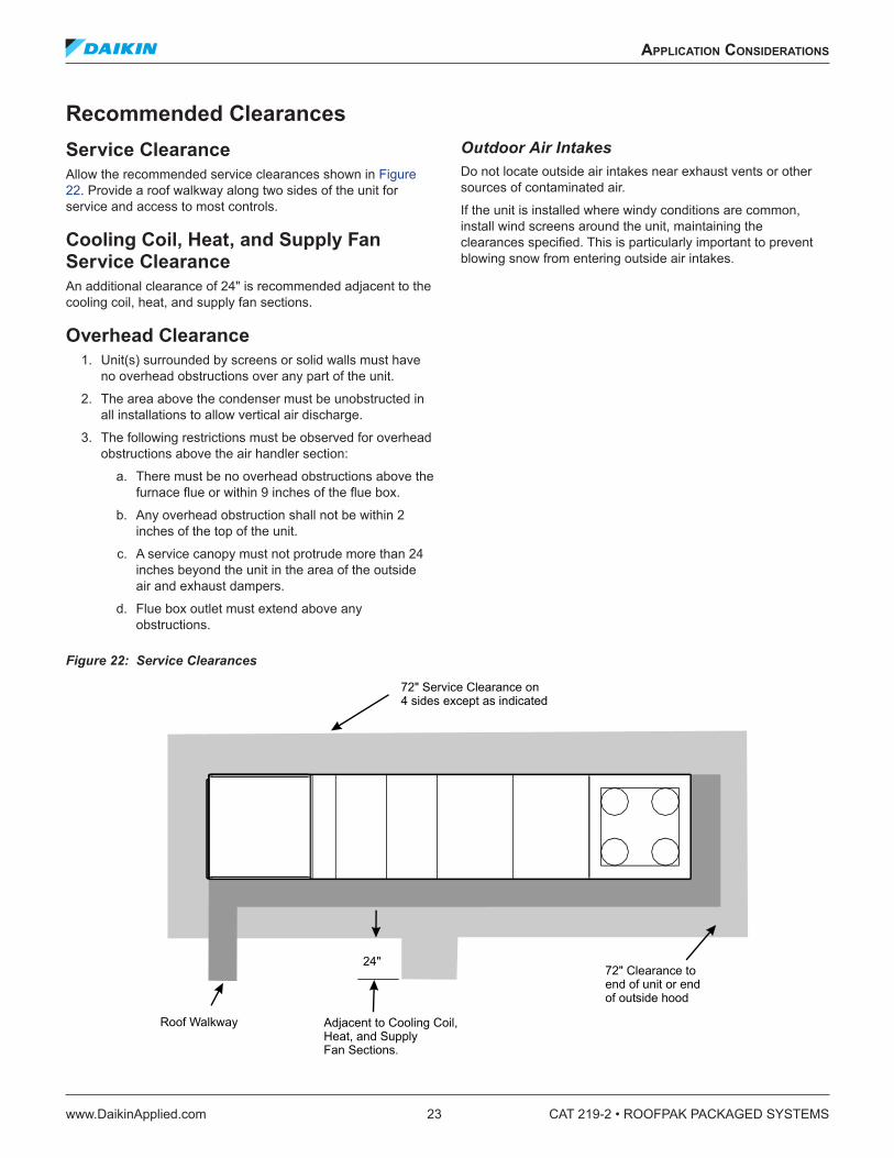
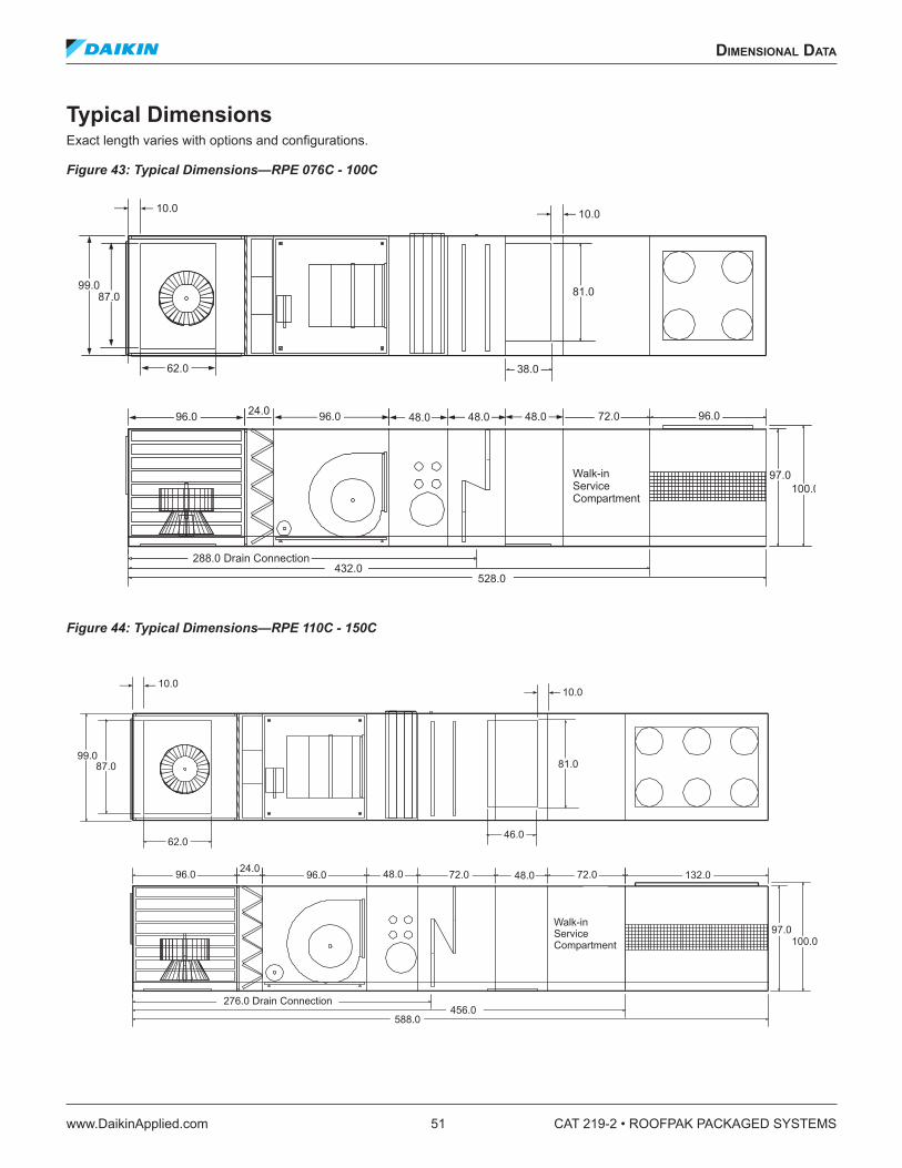
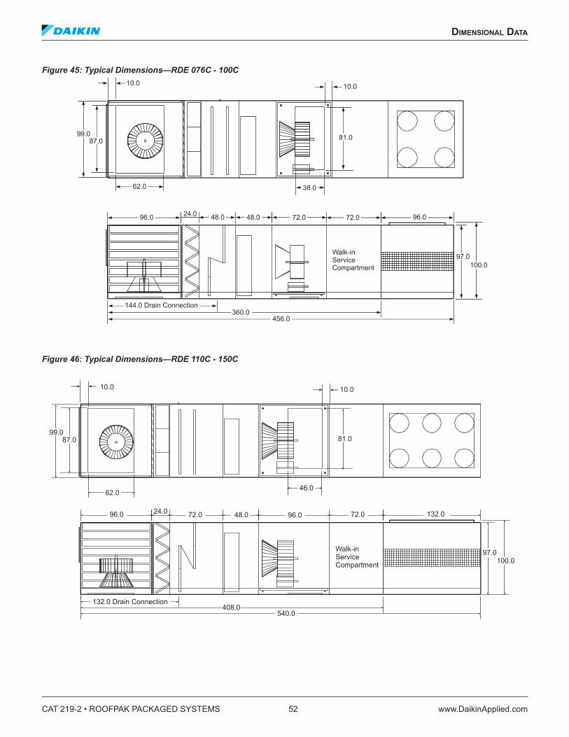
Recommended ClearancesService ClearanceAllow the recommended service clearances shown in Figure 22. Provide a roof walkway along two sides of the unit for service and access to most controls.
Cooling Coil, Heat, and Supply Fan Service ClearanceAn additional clearance of 24" is recommended adjacent to the cooling coil, heat, and supply fan sections.
Overhead Clearance1. Unit(s) surrounded by screens or solid walls must have
no overhead obstructions over any part of the unit.
2. The area above the condenser must be unobstructed in all installations to allow vertical air discharge.
3. The following restrictions must be observed for overhead obstructions above the air handler section:
a. There must be no overhead obstructions above the furnace flue or within 9 inches of the flue box.
b. Any overhead obstruction shall not be within 2 inches of the top of the unit.
c. A service canopy must not protrude more than 24 inches beyond the unit in the area of the outside air and exhaust dampers.
d. Flue box outlet must extend above any obstructions.
Outdoor Air IntakesDo not locate outside air intakes near exhaust vents or other sources of contaminated air.
If the unit is installed where windy conditions are common, install wind screens around the unit, maintaining the clearances specified. This is particularly important to prevent blowing snow from entering outside air intakes.
Figure 22: Service Clearances
Roof Walkway
24"
72" Service Clearance on4 sides except as indicated
72" Clearance toend of unit or endof outside hood
Adjacent to Cooling Coil, Heat, and Supply Fan Sections.
CAT 219-2 • ROOFPAK PACKAGED SYSTEMS 24 www.DaikinApplied.com
applICaTIon ConsIderaTIons
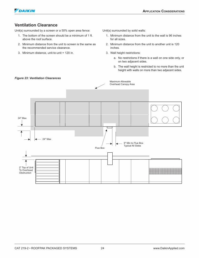
Ventilation ClearanceUnit(s) surrounded by a screen or a 50% open area fence:
1. The bottom of the screen should be a minimum of 1 ft. above the roof surface.
2. Minimum distance from the unit to screen is the same as the recommended service clearance.
3. Minimum distance, unit-to-unit = 120 in.
Unit(s) surrounded by solid walls:
1. Minimum distance from the unit to the wall is 96 inches for all sizes.
2. Minimum distance from the unit to another unit is 120 inches.
3. Wall height restrictions:
a. No restrictions if there is a wall on one side only, or on two adjacent sides.
b. The wall height is restricted to no more than the unit height with walls on more than two adjacent sides.
Figure 23: Ventilation Clearances Maximum AllowableOverhead Canopy Area
9" Min to Flue BoxTypical All Sides
Flue Box
24" Max
24" Max
2" Top of UnitTo OverheadObstruction
applICaTIon ConsIderaTIons
www.DaikinApplied.com 25 CAT 219-2 • ROOFPAK PACKAGED SYSTEMS
Control and Power WiringWiring must be done in accordance with the NEC and local code. For wire sizing instructions, see Supply Power Wiring on page 60.
• All units require 208-60-3, 230-60-3, 460-60-3, 575-60-3 or 380-50-3 power.
• Size wire in accordance with tables 310-16 or 310-19 of the National Electric Code. Wires should be sized for a maximum 3% voltage drop. Copper conductors must be used.
• Actual voltage at the unit connection must be within +/- 10% of nameplate voltage at all times.
• Daikin offers several power connection options.• Single power connection with a terminal block or non-
fused disconnect are normally the most economical.• Systems served by emergency generators often require
two power connections (with terminal blocks or non-fused disconnects). The generator normally serves only the air handler and controls portion so the condensing unit must be powered separately.
• Each unit is provided with a separate 115 volt convenience outlet that requires a separate power connection per the NEC.
• A second, 115 volt power supply is required to power the optional unit heater for the service compartment.
Most units require a zone temperature sensor for night heat and other functions. The sensor must be properly placed so that its temperature reflects the zone requirements. Avoid outside walls, sunlight and close proximity to supply air or heat generating equipment. A return air sensor can be substituted for the space sensor if necessary.
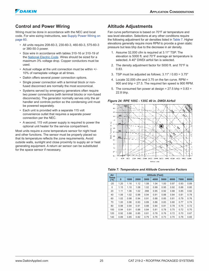
Altitude AdjustmentsFan curve performance is based on 70°F air temperature and sea level elevation. Selections at any other conditions require the following adjustment for air densities listed in Table 7. Higher elevations generally require more RPM to provide a given static pressure but less bhp due to the decrease in air density.
1. Assume 32,000 cfm is required at 3.11" TSP. The elevation is 5000 ft. and 70°F average air temperature is selected. A 40" DWDI airfoil fan is selected.
2. The density adjustment factor for 5000 ft. and 70°F is 0.83.
3. TSP must be adjusted as follows; 3.11" / 0.83 = 3.75"
4. Locate 32,000 cfm and 3.75 on the fan curve. RPM = 900 and bhp = 27.5. The required fan speed is 900 RPM.
5. The consumed fan power at design = 27.5 bhp × 0.83 = 22.8 bhp.
Figure 24: RPE 105C - 135C 40 in. DWDI Airfoil
Table 7: Temperature and Altitude Conversion FactorsAir
CAT 219-2 • ROOFPAK PACKAGED SYSTEMS 26 www.DaikinApplied.com
applICaTIon ConsIderaTIons
Furnace Performance• Gas heat performance data is based on standard 70°F
combustion air temperature and zero feet altitude (sea level).
• Furnace altitude derate may be 4% per 1000 feet above 2000 feet due to lesser combustion air density.
• However, if design ambient is cold enough, then the combined affect of colder temperature and altitude may have an offsetting impact on combustion air density.
Example:A 1000 MBh furnace at 70°F ambient and at an altitude of 5000 feet is derated (0.04 × 3 = 0.12). At 1000 MBh input (1000 × 0.12 MBh), the actual input is (1000 – 120 = 880 MBh) at 5000 feet. Above 6000 feet, consult factory.
Freezing ConcernsFreeze protection measures must be taken for any rooftop exposed to freezing conditions. The owner and building designer must take primary responsibility based on the exact climate and installation conditions.
• Drain all condenser water as soon as the climate allows the economizer to provide all required cooling.
• The optional sump heater is recommended to protect the sump if ambient temperatures can drop to freezing conditions (even at night).
Spray SystemThe spray tree and nozzles are not vulnerable to freezing because water drains out of them when the spray pump is OFF. Remove the sump drain plug whenever the unit is not in operation to prevent precipitation from building up in the sump and drain.
Two freeze protection options are required to prevent the rest of the spray system from freezing.
1. An optional service vestibule heater provides primary freeze protection of the spray system enclosed in the vestibule. A thermostat turns the unit heater on when vestibule temperature drops to 40°F.
2. A sump heater is a recommended option that includes the following:
• An ambient thermostat-controlled insertion heater for the sump.
• Heat tape, insulation and thermostat for the sump drain.
• Heat tape, thermostat and insulation is included on the high pressure, factory water inlet piping upstream of the float control valve. An additional 10 feet of heat tape is provided to protect field connections. The installer must provide additional heat tape as required and insulate all field piping.
• An emergency drain solenoid opens up whenever the sump temperature drops near freezing and the spray system drains onto the roof.
Hot Water and Steam CoilsThe RPE/RDE economizer offers better mixing capability than competitive rooftops but it cannot protect a hydronic coil from localized freezing. Optional air mixers are available to reduce air stratification and freezing concerns.
• Glycol is strongly recommended for hot water coils. It is the only reliable protection in the event of a power failure. Glycol’s impact on coil and pump performance must be considered.
• An optional, non-averaging coil freezestat is offered on the downstream face of the heating coil. The outdoor dampers are shut, the fan is shut off, and the heating valve is fully opened, if freezing temperatures are experienced. The freezestat must be set somewhat above freezing temperatures to improve protection and may experience nuisance trips. It can not protect the coils during a power outage.
• Freeze protection strategies must not cause the cabinet temperature to exceed 150°F or motors and electrical equipment may be damaged.
The field installed supply and bleed off water lines can enter the unit through the floor, inside the curb perimeter. This may provide sufficient protection depending on the temperature inside the curb. Use freeze protection if there is any concern the temperature inside the curb may fall below freezing. If no curb is provided, or field water piping enters the side of the unit, then additional measures are required such as heat tape and proper pipe insulation.
Hot water and steam coil piping can enter the floor of the unit in the heat section and requires similar consideration.
Water TreatmentAll evaporative condensers require proper water treatment. See Optional Water Treatment on page 14.
The purpose of the water treatment system is to:
• Control organic contamination.• Reduce condenser and sump scaling, fouling and
corrosion.• Reduce the required cleaning frequency.
Proper water treatment involves two mandatory components (treatment and bleed off) and may also require a solid separator system depending on water quality.
applICaTIon ConsIderaTIons
www.DaikinApplied.com 27 CAT 219-2 • ROOFPAK PACKAGED SYSTEMS
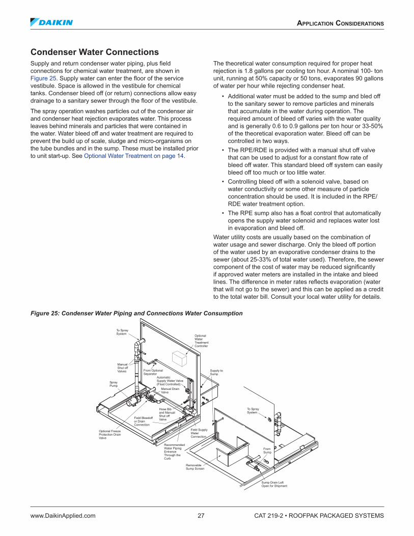
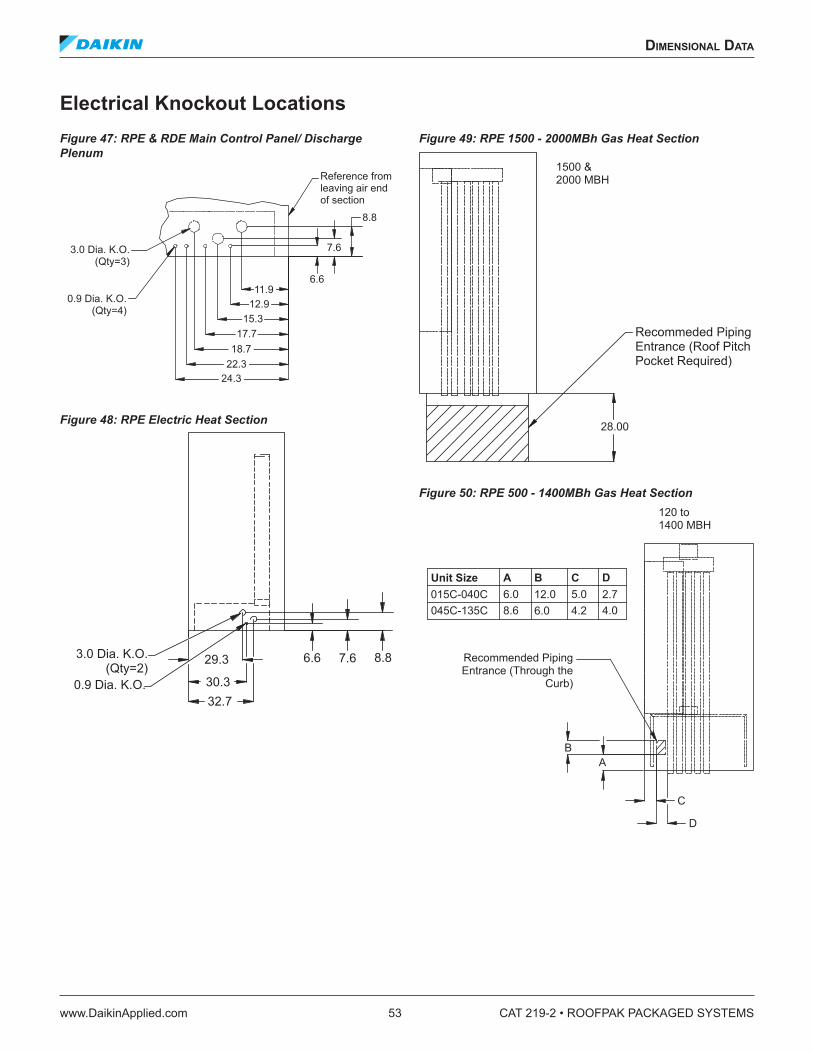
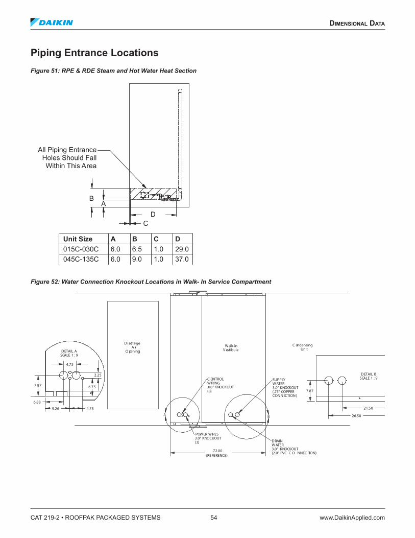
Condenser Water ConnectionsSupply and return condenser water piping, plus field connections for chemical water treatment, are shown in Figure 25. Supply water can enter the floor of the service vestibule. Space is allowed in the vestibule for chemical tanks. Condenser bleed off (or return) connections allow easy drainage to a sanitary sewer through the floor of the vestibule.
The spray operation washes particles out of the condenser air and condenser heat rejection evaporates water. This process leaves behind minerals and particles that were contained in the water. Water bleed off and water treatment are required to prevent the build up of scale, sludge and micro-organisms on the tube bundles and in the sump. These must be installed prior to unit start-up. See Optional Water Treatment on page 14.
The theoretical water consumption required for proper heat rejection is 1.8 gallons per cooling ton hour. A nominal 100- ton unit, running at 50% capacity or 50 tons, evaporates 90 gallons of water per hour while rejecting condenser heat.
• Additional water must be added to the sump and bled off to the sanitary sewer to remove particles and minerals that accumulate in the water during operation. The required amount of bleed off varies with the water quality and is generally 0.6 to 0.9 gallons per ton hour or 33-50% of the theoretical evaporation water. Bleed off can be controlled in two ways.
• The RPE/RDE is provided with a manual shut off valve that can be used to adjust for a constant flow rate of bleed off water. This standard bleed off system can easily bleed off too much or too little water.
• Controlling bleed off with a solenoid valve, based on water conductivity or some other measure of particle concentration should be used. It is included in the RPE/RDE water treatment option.
• The RPE sump also has a float control that automatically opens the supply water solenoid and replaces water lost in evaporation and bleed off.
Water utility costs are usually based on the combination of water usage and sewer discharge. Only the bleed off portion of the water used by an evaporative condenser drains to the sewer (about 25-33% of total water used). Therefore, the sewer component of the cost of water may be reduced significantly if approved water meters are installed in the intake and bleed lines. The difference in meter rates reflects evaporation (water that will not go to the sewer) and this can be applied as a credit to the total water bill. Consult your local water utility for details.
Figure 25: Condenser Water Piping and Connections Water Consumption
SprayPump
Optional FreezeProtection DrainValve
Manual DrainValve
OptionalWaterTreatmentController
Supply toSump
Field Bleedoffor DrainConnection
From OptionalSeparator
To SpraySystem
To SpraySystem
Field SupplyWaterConnection
ManualShut offValves
Hose Biband ManualShut offValve
RecommendedWater PipingEntranceThrough theCurb
AutomaticSupply Water Valve(Float Controlled)
RemovableSump Screen
FromSump
Sump Drain LeftOpen for Shipment
CAT 219-2 • ROOFPAK PACKAGED SYSTEMS 28 www.DaikinApplied.com
applICaTIon ConsIderaTIons
Selection InstructionsBuilding design and unit selection must allow for code compliance and installation limitations. The Daikin Rooftop unit offers excellent flexibility to meet diverse application requirements.
This catalog includes summary performance tables at several operating conditions. Performance at other conditions can be estimated by interpolation but accuracy may suffer. Extrapolation often results in unreliable or damaging operating conditions and should not be used without factory guidance that is available through your local sales representative. Contact your Daikin representative for custom selections at specific design conditions.
Selection ExampleSelection based on design criteria:
• 38,000 supply cfm at 2.00" ESP• 36,000 return cfm at 0.75" ESP• Sea level location using 60 Hertz power• 95/75°F cooling ambient temperature• 80/67°F cooling mixed air temperature [MAT]
Total cooling loads requirements:
• 115 total tons• 87 sensible tons
Total sensible loads allow for:
• 50 hp SAF motor• 25 hp RAF motor
Gas furnace requirements:
• 1520 MBh of design heating• 9" gas pressure available at the unit• Furnace to only be used at design cfm for morning warm
up and night heat• An RPE unit must be used since a furnace, or electric
heat, or final filters are required.
Unit includes:
• Economizer plus return fan• 65% filters plus pre-filters
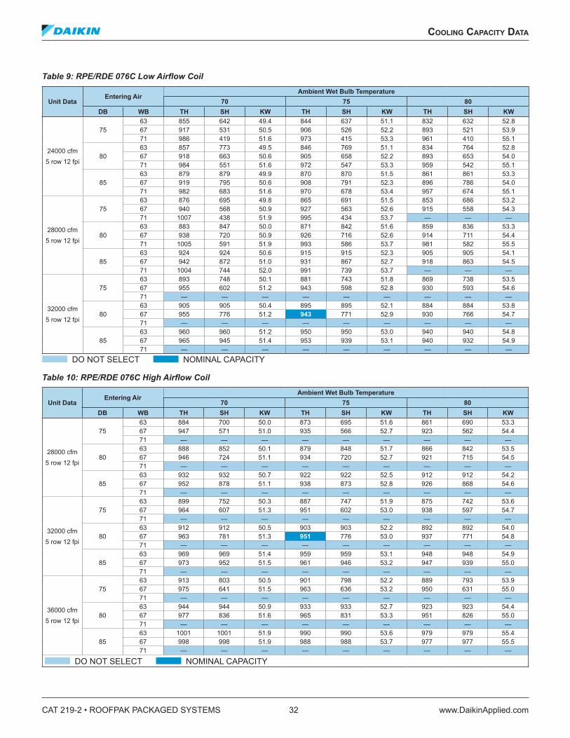
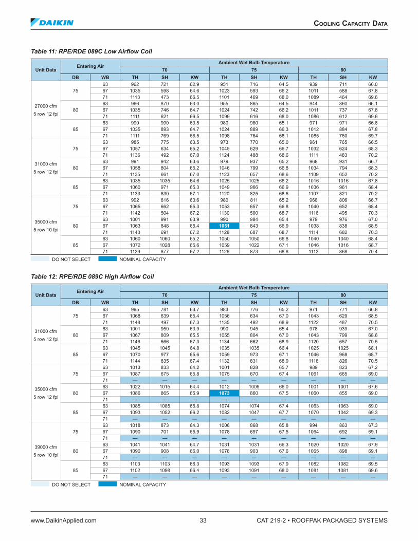
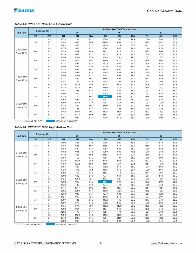
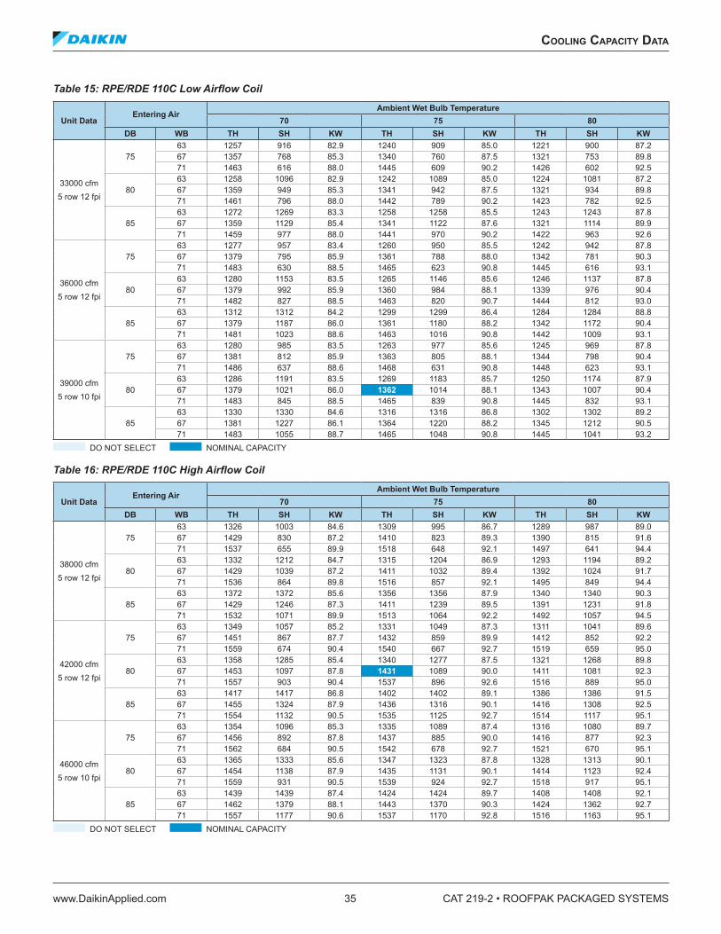
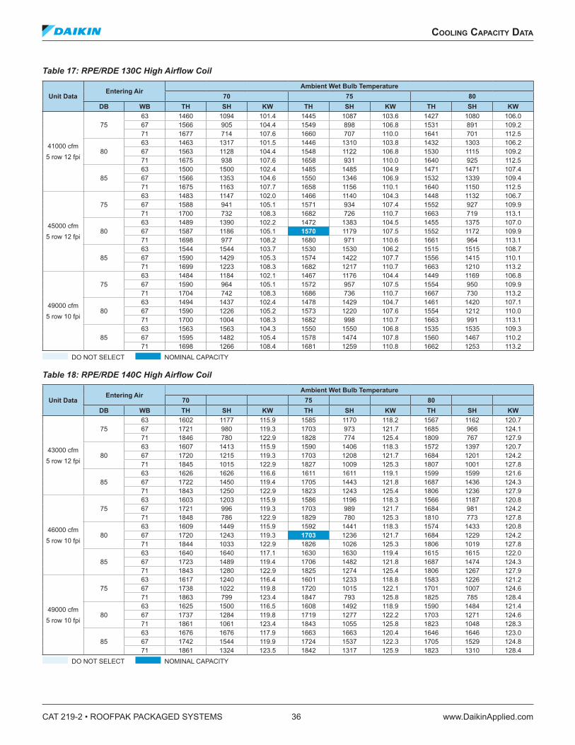
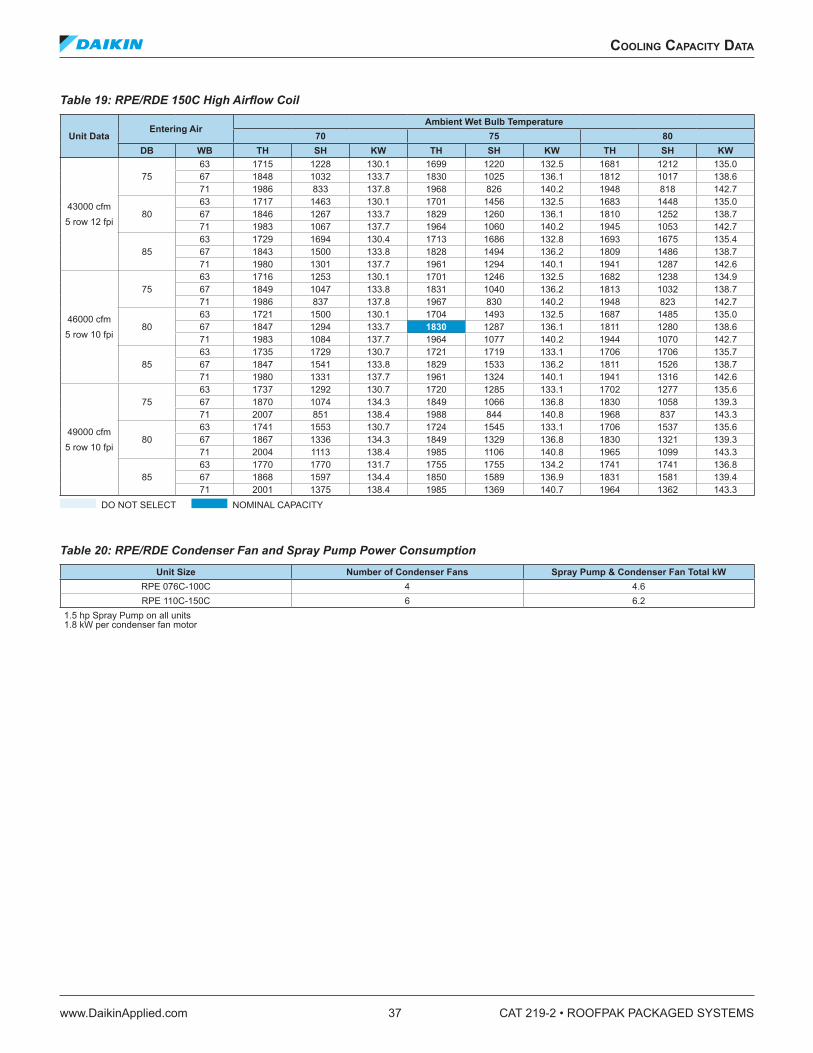
Cooling SelectionGross and net coolingThe tables within the section Cooling Capacity Data on page 32 provide gross cooling or DX coil capacity based on DX coil entering air temperature (EAT).
Net unit cooling capacity = [Gross cooling capacity] - [fan/motor heat]
Fan/motor heat is critical. Refer to Indoor Fan and Motor Heat, Blow-Through vs. Draw-Through Cooling on page 22.
Fan/motor heat = 2800 Btuh per bhp
Fan/motor temperature rise (TR) = Btuh / (1.08 × cfm)
Mixed air vs . entering air temperature [MAT vs . EAT]Draw-through coil EAT = MAT
Blow-through coil EAT = MAT + TR
Blow-through EDB = mixed air EDB + TR
Use a psychometric chart to find blow-through EWB.
Selection From Capacity TablesBlow-through vs. draw-through. Refer to Indoor Fan and Motor Heat, Blow-Through vs. Draw-Through Cooling on page 22.
An RPE is required due to the gas heat requirement. Therefore a draw-through RPE will be considered first.
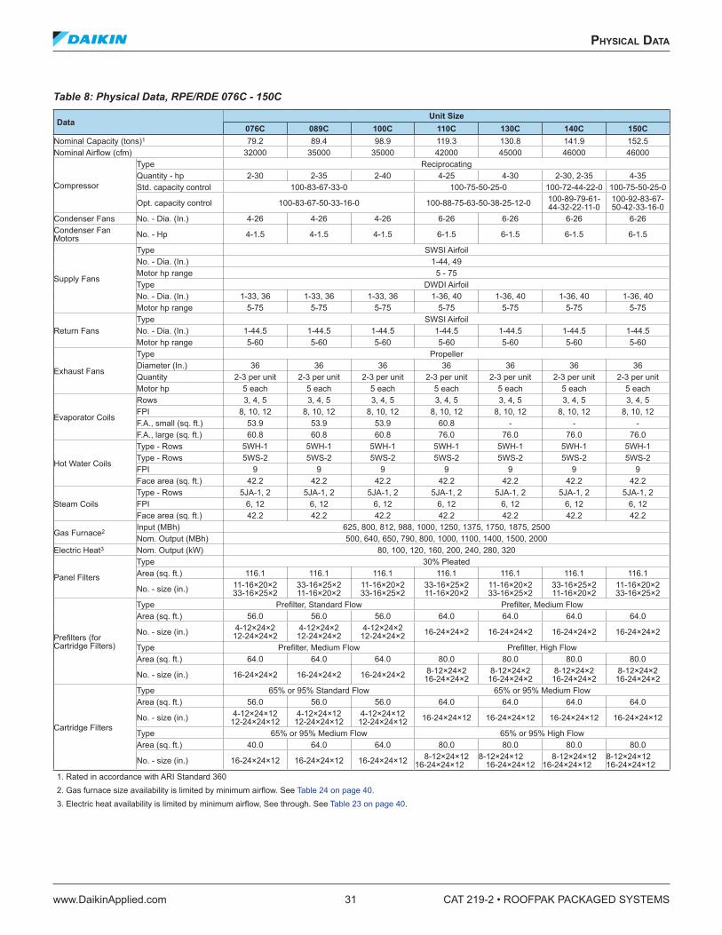
The RPE unit is available with both a low and high airflow DX coil. Refer to Table 8: Physical Data, RPE/RDE 076C - 150C on page 31.
First select a high and low airflow coil with sufficient capacity. The RPE 110 with high airflow coil has sufficient capacity.
No low airflow coil has sufficient capacity.
Check coil velocity on all possible selections.
High airflow face area = 76.0 square feet face velocity = 526 feet per minute.
Low airflow face area = 60.8 square feet face velocity = 658 feet per minute
The low airflow velocity is too much per Unit Operating Range on page 21.
The RPE 110 [with high airflow coil] is sufficient per Table 16 on page 35.
RPE 110 provides 117.6 total tons.
RPE 110 provides 90.8 tons of sensible capacity.
RPE 110 power consumption.
90.0 compressor kW (see Table 16 on page 35).
4.0 condenser fan and pump kW (see Table 20 on page 37). RPE 110 fan and motor heat must still be verified to be less than 50 = 25 bhp [per “fan selection”] to be sure that net cooling capacity is sufficient.
applICaTIon ConsIderaTIons
www.DaikinApplied.com 29 CAT 219-2 • ROOFPAK PACKAGED SYSTEMS
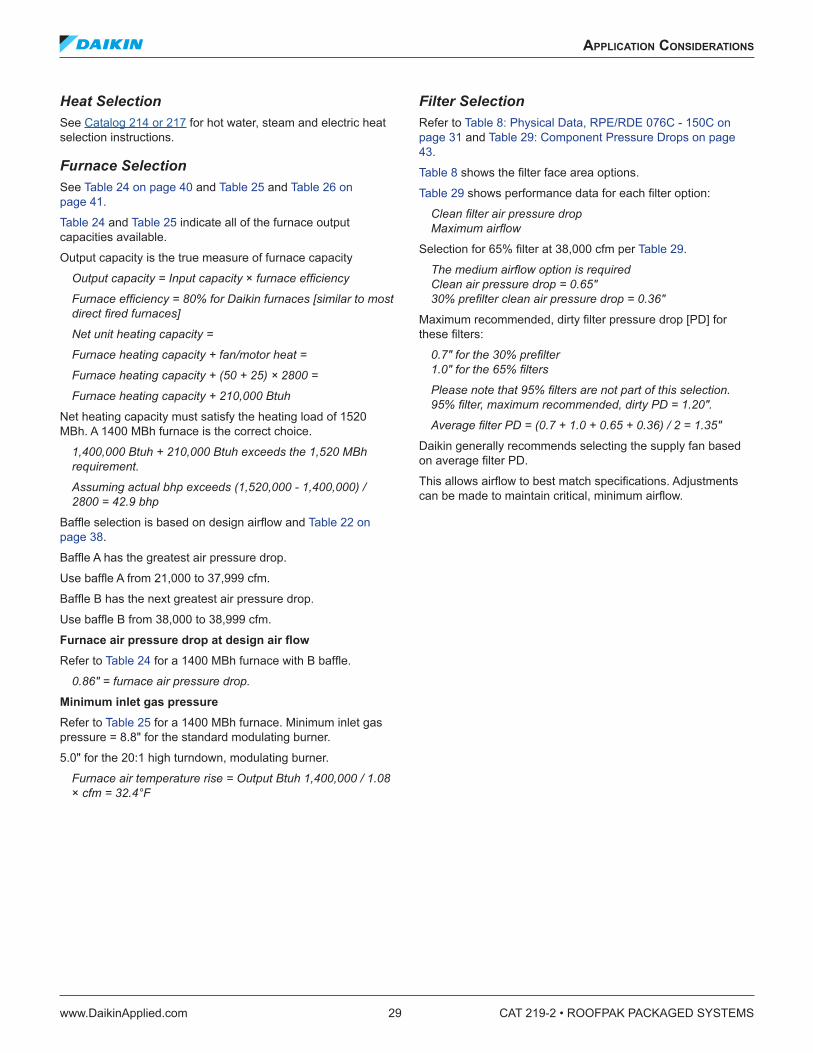
Heat SelectionSee Catalog 214 or 217 for hot water, steam and electric heat selection instructions.
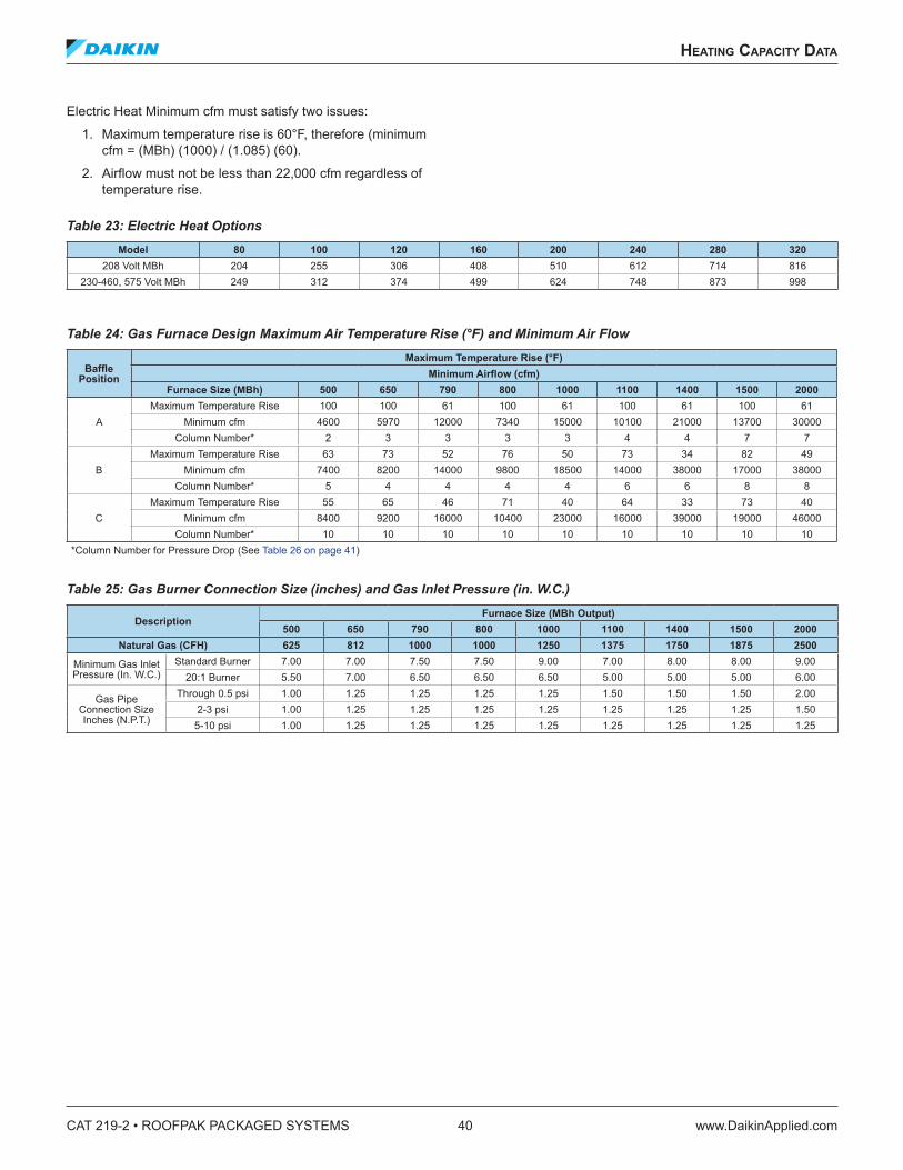
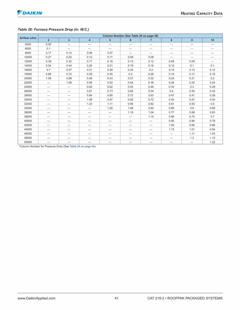
Furnace SelectionSee Table 24 on page 40 and Table 25 and Table 26 on page 41.
Table 24 and Table 25 indicate all of the furnace output capacities available.
Output capacity is the true measure of furnace capacity
CAT 219-2 • ROOFPAK PACKAGED SYSTEMS 30 www.DaikinApplied.com
applICaTIon ConsIderaTIons
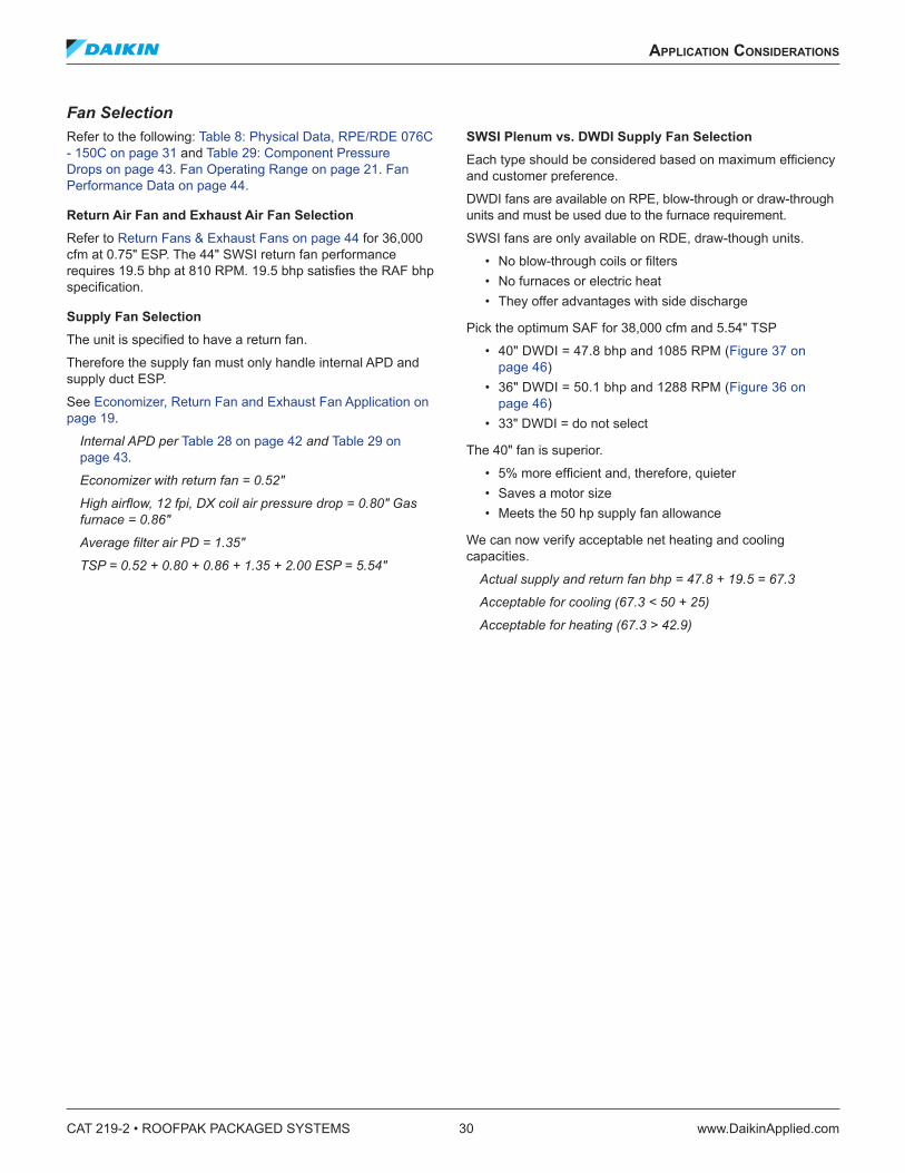
Fan SelectionRefer to the following: Table 8: Physical Data, RPE/RDE 076C - 150C on page 31 and Table 29: Component Pressure Drops on page 43. Fan Operating Range on page 21. Fan Performance Data on page 44.
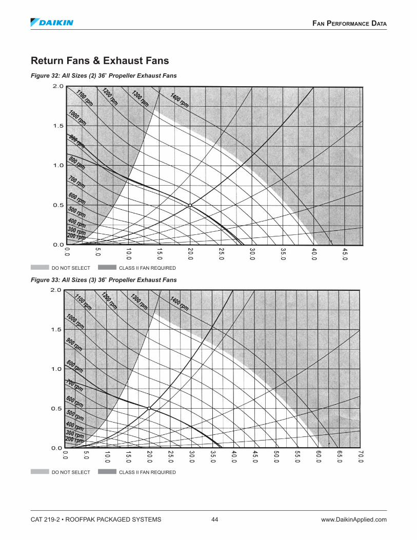
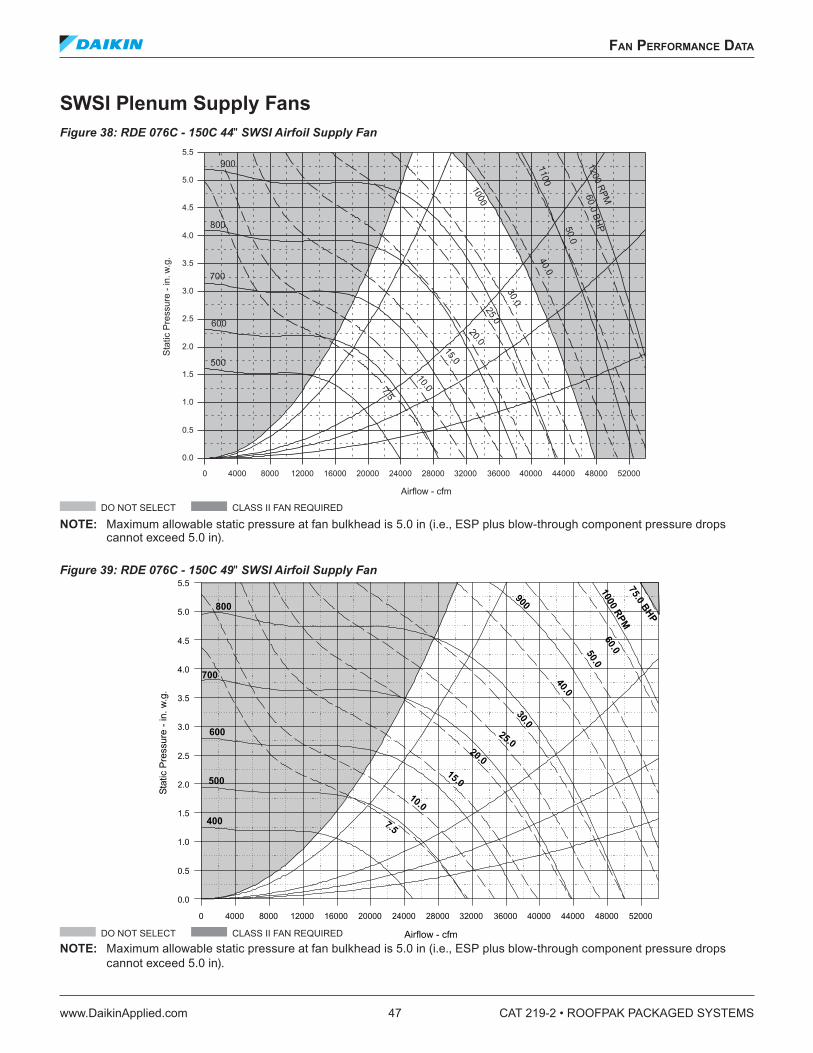
Return Air Fan and Exhaust Air Fan SelectionRefer to Return Fans & Exhaust Fans on page 44 for 36,000 cfm at 0.75" ESP. The 44" SWSI return fan performance requires 19.5 bhp at 810 RPM. 19.5 bhp satisfies the RAF bhp specification.
Supply Fan SelectionThe unit is specified to have a return fan.
Therefore the supply fan must only handle internal APD and supply duct ESP.
See Economizer, Return Fan and Exhaust Fan Application on page 19.
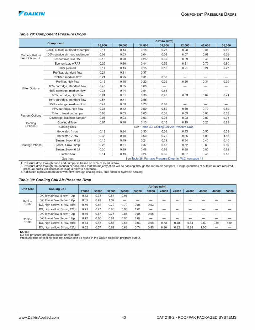
Internal APD per Table 28 on page 42 and Table 29 on page 43.
Economizer with return fan = 0.52"
High airflow, 12 fpi, DX coil air pressure drop = 0.80" Gas furnace = 0.86"
Type PropellerDiameter (In.) 36 36 36 36 36 36 36Quantity 2-3 per unit 2-3 per unit 2-3 per unit 2-3 per unit 2-3 per unit 2-3 per unit 2-3 per unitMotor hp 5 each 5 each 5 each 5 each 5 each 5 each 5 each
1. Rated in accordance with ARI Standard 3602. Gas furnace size availability is limited by minimum airflow. See Table 24 on page 40.3. Electric heat availability is limited by minimum airflow, See through. See Table 23 on page 40.
CAT 219-2 • ROOFPAK PACKAGED SYSTEMS 32 www.DaikinApplied.com
*Column Number for Pressure Drop (See Table 24 on page 40)
CAT 219-2 • ROOFPAK PACKAGED SYSTEMS 42 www.DaikinApplied.com
gas pIpIng sChemaTIC
gas pIpIng sChemaTIC
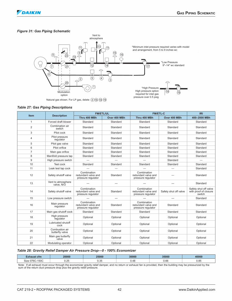
Figure 31: Gas Piping Schematic
Table 27: Gas Piping Descriptions
Item DescriptionFM/ETL/UL FM/ETL-C IRI
Thru 400 MBh Over 400 MBh Thru 400 MBh Over 400 MBh 400–2000 MBh1 Forced draft blower Standard Standard Standard Standard Standard
2 Combination air switch Standard Standard Standard Standard Standard
3 Pilot cock Standard Standard Standard Standard Standard
4 Pilot pressure regulator Standard Standard Standard Standard Standard
5 Pilot gas valve Standard Standard Standard Standard Standard6 Pilot orifice Standard Standard Standard Standard Standard7 Main gas orifice Standard Standard Standard Standard Standard8 Manifold pressure tap Standard Standard Standard Standard Standard9 High pressure switch — — — Standard —
10 Test cock Standard Standard Standard Standard Standard11 Leak test tap cock — — — — Standard
12 Safety shutoff valveCombination
redundant valve and pressure regulator
StandardCombination
redundant valve and pressure regulator
— Standard
13 Vent to atmosphere valve, N/O — — — — Standard
14 Safety shutoff valveCombination
redundant valve and pressure regulator
StandardCombination
redundant valve and pressure regulator
Safety shut off valveSafety shut off valve with proof of closure
switch15 Low pressure switch — — — — Standard
16 Main pressure regulator
Combination redundant valve and pressure regulator
StandardCombination
redundant valve and pressure regulator
Standard Standard
17 Main gas shutoff cock Standard Standard Standard Standard Standard
18 High pressure regulator Optional Optional Optional Optional Optional
Size 076C-150C 0.25 0.35 0.48 0.66 0.85Note: If all exhaust must occur through the economizer gravity relief damper, and no return or exhaust fan is provided, then the building may be pressurized by the sum of the return duct pressure drop plus the gravity relief pressure.
22 109
9
6
2 5
20
4
1
12 14
1516
17
18 19
1918164
13
3
7 21
11 11
Natural gas shown. For LP gas, delete
Modulation option
Vent toatmosphere
*Low Pressure 9"–14" wc standard
*High Pressure High pressure optionrequired for inlet gas
pressure over 0.5 psig
*Minimum inlet pressure required varies with model and arrangement, from 5 to 9 inches wc
ComponenT pressure drops
www.DaikinApplied.com 43 CAT 219-2 • ROOFPAK PACKAGED SYSTEMS
Electric heat 0.14 0.19 0.24 0.30 0.37 0.45 0.53Gas heat See Table 26: Furnace Pressure Drop (in. W.C.) on page 41
1. Pressure drop through hood and damper is based on 30% of listed airflow.2. Pressure drop through the economizer assumes that the majority of air will be passing through the return air dampers. If large quantities of outside air are required,
pressure drops will increase causing airflow to decrease.3. A diffuser is provided on units with blow-through cooling coils, final filters or hydronic heating.
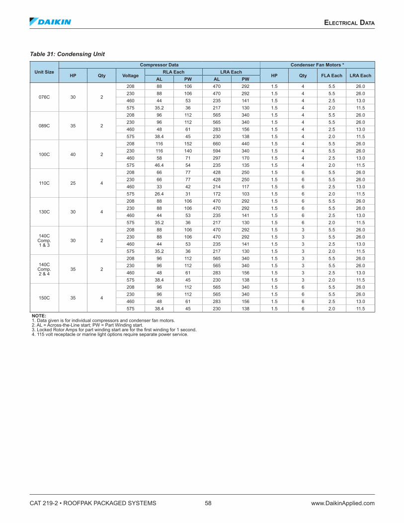
NOTE: 1. Data given is for individual compressors and condenser fan motors.2. AL = Across-the-Line start; PW = Part Winding start.3. Locked Rotor Amps for part winding start are for the first winding for 1 second.4. 115 volt receptacle or marine light options require separate power service.
eleCTrICal daTa
www.DaikinApplied.com 59 CAT 219-2 • ROOFPAK PACKAGED SYSTEMS
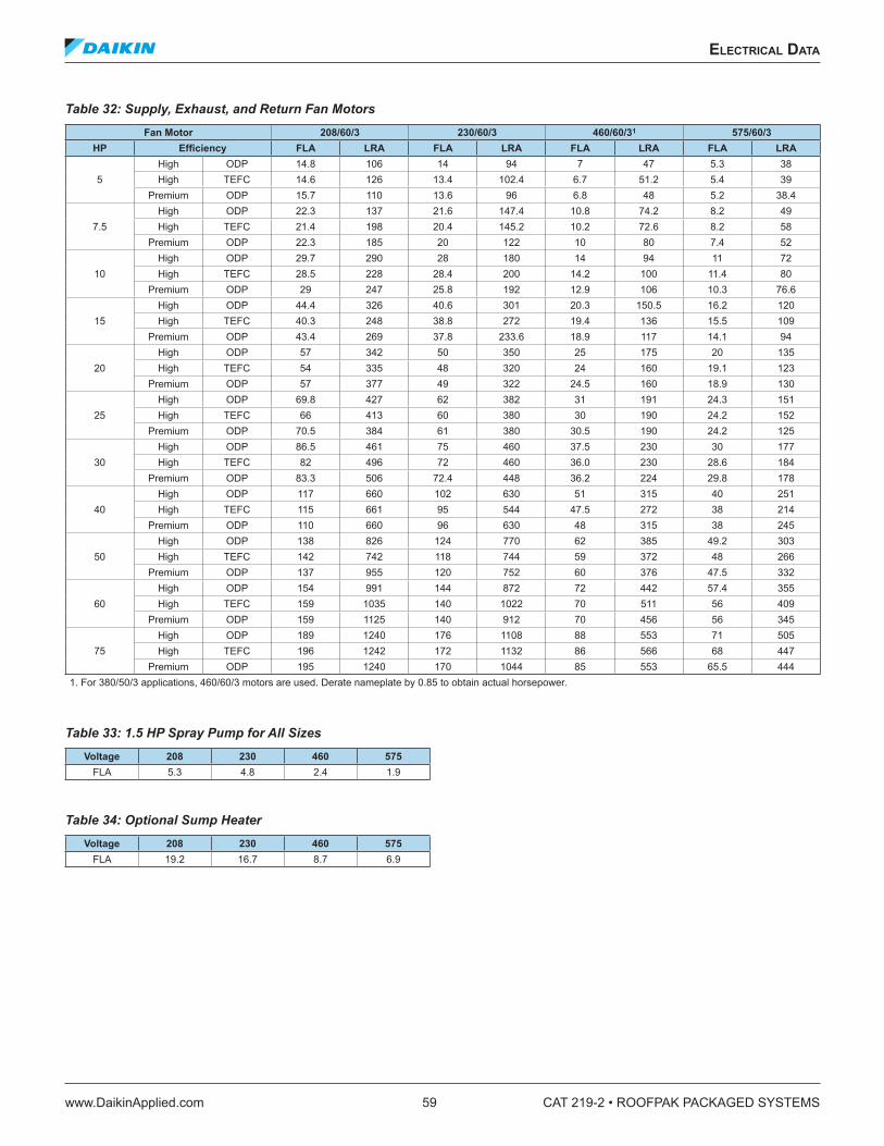
Table 32: Supply, Exhaust, and Return Fan MotorsFan Motor 208/60/3 230/60/3 460/60/31 575/60/3
Premium ODP 195 1240 170 1044 85 553 65.5 4441. For 380/50/3 applications, 460/60/3 motors are used. Derate nameplate by 0.85 to obtain actual horsepower.
Table 33: 1.5 HP Spray Pump for All SizesVoltage 208 230 460 575
1. Units require three-phase power supply.2. Allowable voltage tolerances:
a. 60 HertzNameplate 208V: Min. 187V, Max. 229V Nameplate 230V: Min. 207V, Max. 253V Nameplate 460V: Min. 414V, Max. 506V Nameplate 575V: Min. 518V, Max. 633V
b. 50 HertzNameplate 380V: Min. 360V, Max. 418V
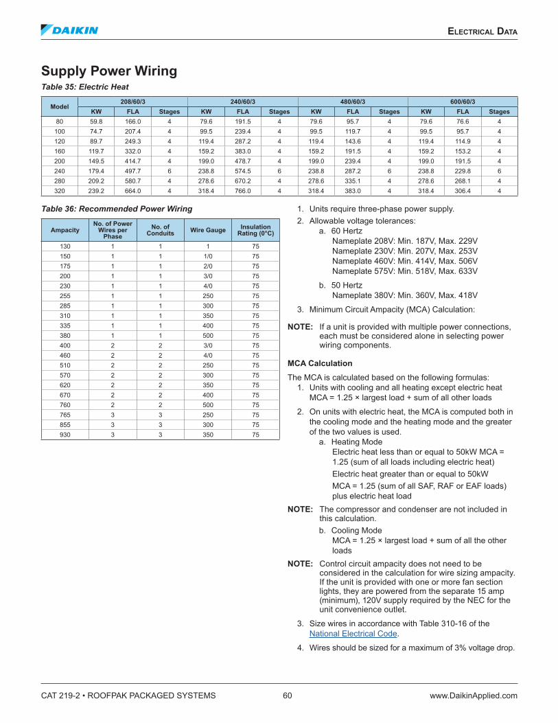
3. Minimum Circuit Ampacity (MCA) Calculation:
NOTE: If a unit is provided with multiple power connections, each must be considered alone in selecting power wiring components.
MCA CalculationThe MCA is calculated based on the following formulas:
1. Units with cooling and all heating except electric heat MCA = 1.25 × largest load + sum of all other loads
2. On units with electric heat, the MCA is computed both in the cooling mode and the heating mode and the greater of the two values is used.
a. Heating ModeElectric heat less than or equal to 50kW MCA = 1.25 (sum of all loads including electric heat)Electric heat greater than or equal to 50kWMCA = 1.25 (sum of all SAF, RAF or EAF loads) plus electric heat load
NOTE: The compressor and condenser are not included in this calculation.b. Cooling Mode
MCA = 1.25 × largest load + sum of all the other loads
NOTE: Control circuit ampacity does not need to be considered in the calculation for wire sizing ampacity. If the unit is provided with one or more fan section lights, they are powered from the separate 15 amp (minimum), 120V supply required by the NEC for the unit convenience outlet.
3. Size wires in accordance with Table 310-16 of the National Electrical Code.
4. Wires should be sized for a maximum of 3% voltage drop.
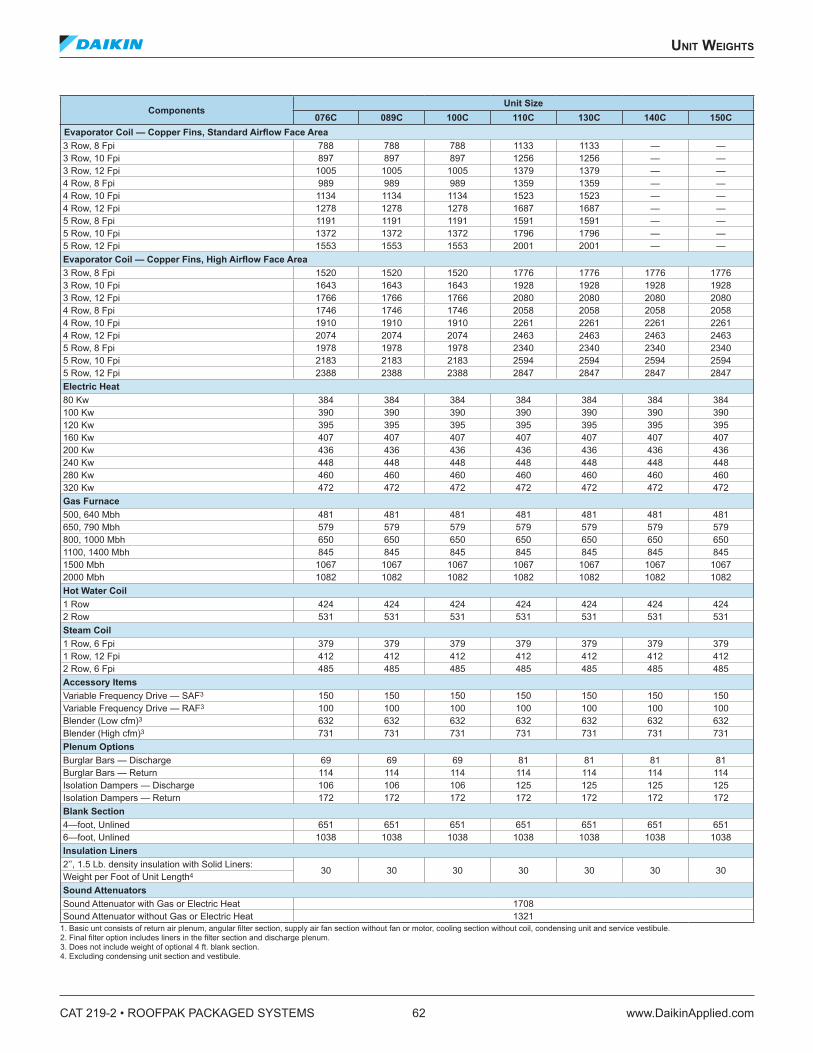
30 30 30 30 30 30 30Weight per Foot of Unit Length4
Sound AttenuatorsSound Attenuator with Gas or Electric Heat 1708Sound Attenuator without Gas or Electric Heat 1321
1. Basic unt consists of return air plenum, angular filter section, supply air fan section without fan or motor, cooling section without coil, condensing unit and service vestibule.2. Final filter option includes liners in the filter section and discharge plenum.3. Does not include weight of optional 4 ft. blank section.4. Excluding condensing unit section and vestibule.
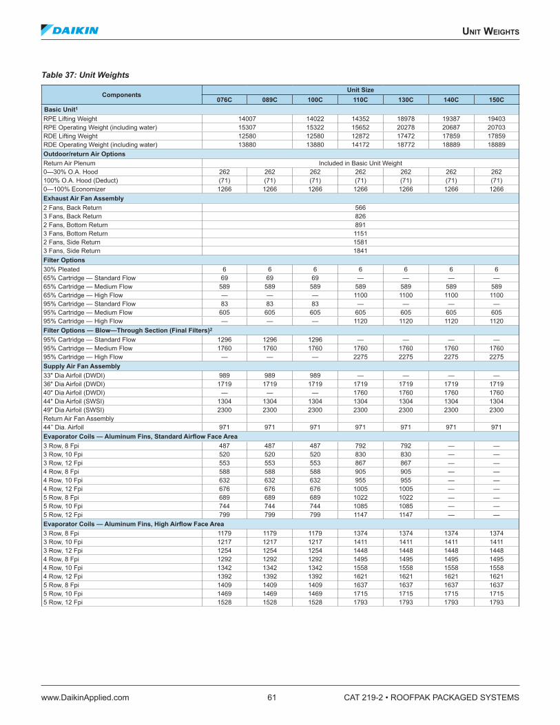
unIT WeIghTs
www.DaikinApplied.com 63 CAT 219-2 • ROOFPAK PACKAGED SYSTEMS
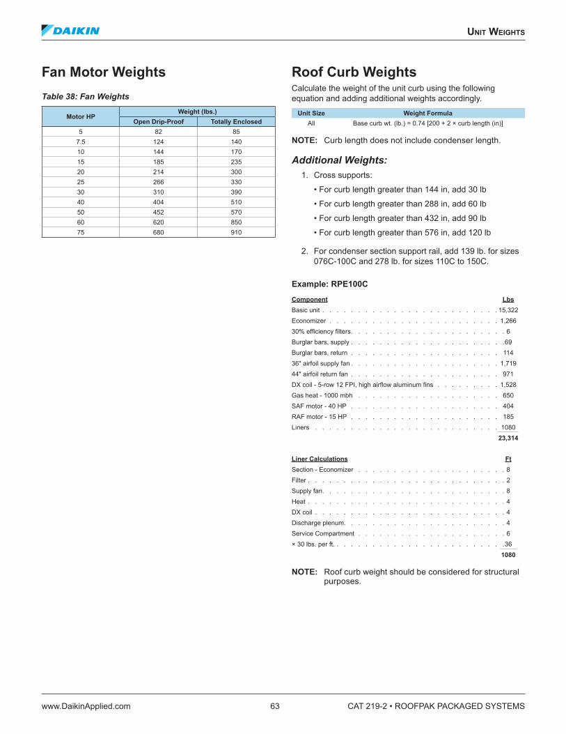
NOTE: Roof curb weight should be considered for structural purposes.
CAT 219-2 • ROOFPAK PACKAGED SYSTEMS 64 www.DaikinApplied.com
engIneerIng guIde speCIfICaTIon
engIneerIng guIde speCIfICaTIon
RoofPak Singlezone Heating and Cooling Unit(s)
GeneralA. The complete unit shall be [ETL/MEA] [ETL-Canada]
listed. [The burner and gas train for the unit furnace shall be [IRI/FIA] [FM] approved.]
B. Each unit shall be specifically designed for outdoor rooftop application and include a weatherproof cabinet. Units shall be of a modular design with factory installed access sections available to provide maximum design flexibility. Each unit shall be [completely factory assembled and shipped in one piece] [split between the supply fan section and the heat section]. All packaged units shall be shipped fully charged with Refrigerant [22] [407C].
C. The unit shall undergo a complete factory run test prior to shipment and factory test sheets shall be available upon request. The factory test shall include final balancing of the supply [and return] fan assemblies, a refrigeration circuit run test, a unit control system operations checkout, [test and adjustment of the gas furnace], a unit refrigerant leak test and a final unit inspection.
D. All units shall have decals and tags to indicate caution areas and aid unit service. Unit nameplates shall be fixed to the main control panel door. Electrical wiring diagrams shall be attached to the control panels. Installation, operating and maintenance bulletins and start-up forms shall be supplied with each unit.
E. Performance: All scheduled capacities and face areas are minimum accepted values. All scheduled amps, kW, and HP are maximum accepted values that allow scheduled capacity to be met.
F. Warranty: The manufacturer shall provide 12-month parts only warranty. [The manufacturer will provided extended 48-month, parts only, warranty on the compressor.] Defective parts will be repaired or replaced during the warranty period at no charge. The warranty period shall commence at startup or six months after shipment, whichever occurs first.
Cabinet, Casing and FrameA. Standard double-wall construction for all side wall
access doors and floor areas shall be provided with 22 gauge solid galvanized steel inner liners to protect insulation during service and maintenance. Insulation shall be a minimum of 1" thick, 3/4 lb. density neoprene coated glass fiber. Unit cabinet shall be designed to operate at total static pressures up to 6.5 inches w.g. Insulation on ceiling and end panels shall be secured with adhesive and mechanical fasteners. [Heavy gauge solid galvanized steel liners shall be provided throughout, allowing no exposed insulation within the air stream. All cabinet insulation, except floor panels, shall be a nominal 2" thick, 1½ lb. density, R6.5, glass fiber.] [A combination of solid and perforated galvanized steel liners shall be provided throughout. Perforated liners to be used in the supply and return air plenums to provide improved sound attenuation. All cabinet insulation, except floor panels, shall be a nominal 2" thick, 1½ lb. density, R6.5, glass fiber.] All floor panels shall include [double wall construction and include a nominal 2" thick, 1½ lb. density, R6.5 glass fiber insulation.] [a minimum 1" thick, 3 lb. density, R4.2 glass fiber glass insulation.]
B. Exterior surfaces shall be constructed of pre-painted galvanized steel for aesthetics and long term durability. Paint finish to include a base primer with a high quality, polyester resin topcoat of a neutral beige color. Finished surface to withstand a minimum 750-hour salt spray test in accordance with ASTM B117 standard for salt spray resistance. Service doors shall be provided on both sides of each section in order to provide user access to all unit components. Service doors shall be constructed of heavy gauge galvanized steel with a gauge galvanized steel interior liner. All service doors shall be mounted on multiple, stainless steel hinges and shall be secured by a latch system that is operated by a single, flush mounted handle. The latch system shall feature a staggered engagement for ease of operation. Removable panels, or doors secured by multiple, mechanical fasteners are not acceptable.
C. The unit base frame shall be constructed of 13-gauge pre-painted galvanized steel. The unit base shall overhang the roof curb for positive water runoff and shall have a formed recess that seats on the roof curb gasket to provide a positive, weathertight seal. Lifting brackets shall be provided on the unit base with lifting holes to accept cable or chain hooks.
engIneerIng guIde speCIfICaTIon
www.DaikinApplied.com 65 CAT 219-2 • ROOFPAK PACKAGED SYSTEMS
Supply and Return FansA. All fan assemblies shall be statically and dynamically
balanced at the factory, including a final trim balance, prior to shipment. All fan assemblies shall employ solid steel fan shafts. Heavy-duty pillow block type, self-aligning, grease lubricated ball bearings shall be used. Bearings shall be sized to provide an L-50 life at 200,000 hours. The entire fan assembly shall be isolated from the fan bulkhead and mounted on [rubber in shear isolators] [spring isolators] [spring isolators with seismic restraints]. [Fixed] [Adjustable] pitch V-belt drives with matching belts shall be provided. V-belt drives shall be selected at [the manufacturer’s standard service factor] [1.5 times fan brake horsepower].
B. Fan motors shall be heavy-duty 1800 rpm [open drip-proof (ODP)] [totally enclosed TEFC] type with grease lubricated ball bearings. [Motors shall be high efficiency and meet applicable EPACT requirements.] [Motors shall be premium efficiency.] Motors shall be mounted on an adjustable base that provides for proper alignment and belt tension adjustment.
C. Airfoil supply fans1. RDE supply fan shall be single width, single inlet
(SWSI) airfoil centrifugal fan. The fan wheel shall be Class II construction with aluminum fan blades continuously welded to the back plate and end rim. Fans shall be mounted using shafts and hubs with mating keyways.
2. RPE supply fan shall be double width, double inlet (DWDI) airfoil centrifugal fan. All fans shall be mounted using shafts and hubs with mating keyways. Fans shall be Class II type and fabricated from heavy-gauge aluminum. Fan blades shall be continuously welded to the back plate and end rim.
D. Airfoil return fansA single width, single inlet (SWSI) airfoil centrifugal return air fan shall be provided. The fan shall be Class II construction. The fan wheel shall be Class II construction and fabricated from heavy-gauge aluminum with fan blades continuously welded to the back plate and end rim. The fan shall be mounted using shafts and hubs with mating keyways. Exhaust fans are not acceptable.
E. [The supply air fan and return air fan sections shall be provided with an expanded metal belt guard.]
Propeller Exhaust FansA. Belt drive propeller exhaust fans shall be provided.
Propellers shall be constructed with fabricated steel, and shall be securely attached to fan shafts. All propellers shall be statically and dynamically balanced. Motors shall be permanently lubricated, heavy-duty type, carefully matched to the fan load. Ground and polished steel fan shafts shall be mounted in permanently lubricated, sealed ball bearing pillow blocks. Bearings shall be selected for a minimum (L10) life in excess of 100,000 hours at maximum cataloged operating speeds. Drives shall be sized for a minimum of 105 percent of driven horsepower.Pulleys shall be of the fully machined cast iron type, keyed and securely attached to wheel and motor shafts. Motor sheaves shall be adjustable for system balancing. Drive frame and panel assemblies shall be galvanized steel. Drive frames shall be formed channels and panels shall be welded construction. The axial exhaust or supply fans shall bear the AMCA Certified Ratings Seals for both sound and air performance. Return fans are not acceptable.
B. The exhaust fans shall be controlled by a variable frequency drive.
C. [The exhaust air fan sections shall be provided with an expanded metal belt guard.]
Variable Air Volume ControlA. An electronic variable frequency drive shall be
provided for the supply [and return] air fan. [Two independent drives, one per fan, shall be provided.] Each drive shall be factory installed downstream of the filters in a manner that the drive(s) are directly cooled by the filtered, mixed air stream. Drives shall meet UL Standard 95-5V and the variable frequency drive manufacturer shall have specifically approved them for plenum duty application. The completed unit assembly shall be listed by a recognized safety agency, such as ETL. Drives are to be accessible through a hinged door assembly complete with a single handle latch mechanism. Mounting arrangements that expose drives to high temperature, unfiltered ambient air is not acceptable.
B. The unit manufacturer shall install all power and control wiring. [A manual bypass contactor arrangement shall be provided. The bypass arrangement will allow fan operation at full design CFM, even if the drive has been removed for service]. [Line reactors shall be factory installed for each drive].
CAT 219-2 • ROOFPAK PACKAGED SYSTEMS 66 www.DaikinApplied.com
engIneerIng guIde speCIfICaTIon
C. The supply air fan drive output shall be controlled by the factory installed main unit control system and drive status and operating speed shall be monitored and displayed at the main unit control panel. [The supply and return/exhaust fan drive outputs shall be independently controlled in order to provide the control needed to maintain building pressure control. Supply and return/exhaust air fan drives that are slaved off of a common control output are not acceptable.]
D. All drives shall be factory run tested prior to unit shipment.
ElectricalA. Unit wiring shall comply with NEC requirements
and with all applicable UL standards. All electrical components shall be UL recognized where applicable. All wiring and electrical components provided with unit shall be number and color-coded and labeled according to the electrical diagram provided for easy identification. The unit shall be provided with a factory wired weatherproof control panel. Unit shall have a [single] [dual] point power terminal block for main power connection. A terminal board shall be provided for low voltage control wiring. Branch short circuit protection, 115 volt control circuit transformer and fuse, system switches and high temperature sensor shall also be provided with unit. Each compressor and condenser fan motor shall be furnished with contactors and inherent thermal overload protection. Supply and return fan motors shall have contactors and external overload protection. Knockouts shall be provided in the bottom of the main control panels for field wiring entrance. All 115-600 voltage wire shall be protected from damage by raceways or conduit.
B. [A factory installed and wired marine service light, with switch and receptacle, shall be provided in the supply air and return/exhaust fan section. The separate, main unit service receptacle electrical circuit shall also power the light circuit.]
C. [Part winding start shall be provided for the unit compressors to reduce inrush current at start-up.]
D. [Power factor capacitors shall be factory mounted and wired to the unit compressors. Power factor capacitors shall be selected to provide correction to a minimum of 0.90.]
E. [Phase failure and under voltage protection on three-phase motors shall be provided to prevent damage from single phasing, phase reversal, and low voltage conditions.]
F. [Ground fault protection shall be provided to protect against arcing ground faults.]
G. Further options1. Factory mounted smoke detectors shall be
factory installed in the [supply air opening] [supply and return air openings]. Smoke detectors to be ionization type, which responds to invisible products of combustion without requiring the sensing of heat, flame or visible smoke. Upon sensing smoke, the unit shall provide a control output for use by building management system.
2. Unit to have factory-mounted UV lights located on the leaving air side of the cooling coil. Unit to have view port to allow for visual indication of operation through UV resistant glass. Unit to have door interlocks on each door accessing UV light. Interlock to kill power to UV light when door is opened.Lamp and fixture to consist of a housing, power source, lamp sockets, and lamp. All components are to be constructed to withstand typical HVAC environments and are UL/C-UL listed. Housings are to be constructed of type 304 stainless steel and are to be equipped with both male and female power plugs with one type at each end to facilitate simple fixture-to-fixture plug-in for AC power.Power source shall be an electric, rapid-type with overload protections and is to be designed to maximize radiance and reliability at UL/C-UL listed temperatures of 55°F-135°F. Power source will include RF and EMI suppression.Sockets shall be medium bi-pin, single click safety, twist lock type and are to constructed of a UVC-resistant polycarbonate.Lamp shall be a high output, hot cathode, T8 diameter, medium bi-pin that produces UVGI of 254 nm. Each tube produces the specified output at 500 fpm and air temperatures of 55°F–135°F.
3. A [single] [dual] non-fused disconnect switch[es] shall be provided for disconnecting electrical power at the unit. [The second switch will service the condensing section.] Disconnect switches shall be mounted internally to the control panel and operated by an externally mounted handle. Externally mounted handle is designed to prohibit opening of the control panel door without the use of a service tool.
4. A GFI 115 volt service outlet shall be provided.a. [The outlet requires a separate 115 volt field-
powered source]b. [The outlet shall be powered by the unit and
include its own disconnect and short circuit protection.]
engIneerIng guIde speCIfICaTIon
www.DaikinApplied.com 67 CAT 219-2 • ROOFPAK PACKAGED SYSTEMS
Cooling and Heating SectionsCooling
A. [The cooling coil section shall be installed in a blow- through configuration, downstream of the supply air fan. A factory-tested diffuser shall be used in order to provide air distribution across the cooling coil. A blow-through coil is specified to minimize the impact of fan motor heat.] [The cooling coil section shall be installed in a draw-through configuration, upstream of the supply air fan.] The coil section shall be complete with factory piped cooling coil and sloped drain pan. Hinged access doors on both sides of the section shall provide convenient access to the cooling coil and drain pan for inspection and cleaning.Submittals must demonstrate that scheduled unit leaving air temperature (LAT) is met, that fan and motor heat temperature rise (TR) have been considered, and scheduled entering air temperature (EAT) equals mixed air temperature (MAT)Draw-through cooling–Scheduled EAT equals cooling coil EAT and scheduled unit LAT equals cooling coil LAT plus TR.Blow-through cooling–Cooling coil EAT equals scheduled EAT plus TR and scheduled unit LAT equals cooling coil LAT.Direct expansion (DX) cooling coils shall be fabricated of seamless 1/2" diameter high efficiency copper tubing that is mechanically expanded into high efficiency [aluminum] [copper] plate fins. Coils shall be a multi-row, staggered tube design with a minimum of [3] [4] [5] rows and a maximum of [8] [10] [12] fins per inch. All units shall have two independent refrigerant circuits and shall use an interlaced coil circuiting that keeps the full coil face active at all load conditions.All coils shall be factory leak tested with high pressure air under water.
B. A [painted galvanized steel,] [stainless steel,] positively sloped drain pan shall be provided with the cooling coil. The drain pan shall extend beyond the leaving side of the coil and underneath the cooling coil connections. The drain pan shall have a minimum slope of 1/8" per foot to provide positive draining. The drain pan shall be connected to a threaded drain connection extending through the unit base. Units with stacked cooling coils shall be provided with a secondary drain pan piped to the primary drain pan.
Hot Water Heating OptionC. A [1] [2] row hot water heating coil shall be factory
installed in the unit heat section. Coils shall be fabricated of seamless 5/8" diameter copper tubing that is mechanically expanded into high efficiency HI F rippled and corrugated aluminum plate fins. All coil vents and drains shall be factory installed. [The hot water heat section shall be installed downstream (RFS/RPS) of the supply air fan. A factory-tested diffuser shall be used in order to provide air distribution across the coil.] [The hot water heat section shall be installed upstream (RDT) of the supply air fan.] Hinged access doors shall provide convenient access to the coil and valve for inspection and cleaning.[A factory installed three-way modulating control valve and spring return valve actuator shall provide control of the hot water coil. The valve actuator shall be controlled by the factory installed main unit control system][[Ethylene glycol] [propylene glycol] shall be added to the hot water circuit to protect against coil freeze-up.][A factory installed, non-averaging type freezestat shall be factory installed to provide some protection against coil freeze-up.]Coils shall be factory leak tested with high pressure air under water.
Steam Heating OptionD. A [1 row, 6 fin per inch] [1 row, 12 fin per inch] [2
row, 6 fin per inch] fin per inch team heating coil shall be factory installed in the unit heat section. Coils shall be fabricated of seamless 5/8" diameter copper tubing that is mechanically expanded into high efficiency HI F rippled and corrugated aluminum plate fins. Steam coils shall be of the jet distributing type. [The steam heat section shall be installed downstream (RFS/RPS) of the supply air fan. A factory-tested diffuser shall be used in order to provide air distribution across the coil.] [The steam heat section shall be installed upstream (RDT) of the supply air fan.] Hinged access doors shall provide convenient access to the coil and valve for inspection and cleaning.[A factory installed two-way modulating control valve and spring return valve actuator shall provide control of the steam coil. The valve actuator shall be controlled by the factory installed main unit control system][A factory installed, non-averaging type freezestat shall be factory installed to provide some protection against coil freeze-up.]Coils shall be factory leak tested with high pressure air under water.
CAT 219-2 • ROOFPAK PACKAGED SYSTEMS 68 www.DaikinApplied.com
engIneerIng guIde speCIfICaTIon
Gas Heating OptionE. A natural gas fired furnace shall be installed in
the unit heat section. The heat exchanger shall include a type 321 stainless steel cylindrical primary combustion chamber, a type 321 stainless steel header, type 321 stainless steel] secondary tubes and type 321stainless steel turbulators. Carbon and aluminized steel heat exchanger surfaces are not acceptable. The heat exchanger shall have a condensate drain. Clean out of the primary heat exchanger and secondary tubes shall be accomplished without removing casing panels or passing soot through the supply air passages. The furnace section shall be positioned downstream of the supply air fan.[The furnace will be supplied with a modulating forced draft burner. The burner shall be controlled for low fire start. The burner shall be capable of continuous modulation between 33% and100% of rated capacity and shall operate efficiently at all firing rates.][The furnace shall be supplied with a Daikin SuperMod forced draft burner capable of continuous modulation between 5% and 100% of rated capacity, without steps. The burner shall operate efficiently at all firing rates. The burner shall have proven open damper low-high-low pre-purge cycle, and proven low fire start. The combustion air control damper shall be in the closed position during the OFF cycle to reduce losses.]The burner shall be specifically designed to burn natural gas and shall include a microprocessor based flame safeguard control, combustion air proving switch, pre-purge timer and spark ignition. The gas train shall include redundant gas valves, [maximum 0.5 psi pressure regulator] [2–3 psi high pressure regulator] [5–10 psi high pressure regulator], shutoff cock, pilot gas valve, pilot pressure regulator, and pilot cock. The burner shall be rated for operation and full modulation capability at inlet gas pressures down to [7.0. W.C. (models 200–650)] [8.0 in. W.C. (models 790, 800, 1100, 1400, 1500)] [9.0 in. W.C. (models 100 and 2000)].The gas burner shall be controlled by the factory installed main unit control system.The burner shall be fired, tested and adjusted at the factory. Final adjustments shall be made in the field at initial start-up by a qualified service technician to verify that installation and operation of the burner is according to specifications.
Electric Heating OptionStaged electric heating coils shall be factory installed in the unit heat section. Heating coils shall be constructed of a low watt density, high nickel chromium alloy resistance wire, mechanically stacked and heli-arc welded to corrosion resistant terminals. A corrosion resistant heavy gauge rack shall support the elements. Safety controls shall include automatic reset high limit control for each heater element with manual reset backup line break protection in each heater element branch circuit (NOTE: Manual reset not provided when ETL-Canada label is provided). Heating element branch circuits shall be individually fused to maximum of 48 Amps per NEC requirements. The electric heat section shall be positioned downstream of the supply air fan.The electric heat elements shall be controlled by the factory installed main unit control system.
FiltersDraw-Through Filters
A. Unit shall be provided with a draw-through filter section.The filter section shall be supplied complete with the filter rack as an integral part of the unit. The draw-through filter section shall be provided with [panel] [cartridge] filters.
B. 2" thick AmericanAirFilter 30% efficient pleated panel filters shall be provided. Filters shall be frame mounted and shall slide into galvanized steel racks contained within the unit. Filters shall be installed in an angular arrangement to maximize filter area and minimize filter face velocity. Filters shall be accessible from both sides of the filter section.
C. [12" deep [60-65%] [90-95%] efficient, UL Std. 900, Class 1, AmericanAirFilter cartridge filters shall be provided. 2" panel, 30% efficient pre-filters shall be included. Cartridge filters shall consist of filter media permanently attached to a metal frame and shall slide into a gasketed, extruded aluminum rack contained within the unit. The filter rack shall have secondary gasketed, hinged end panels to insure proper sealing. Filters shall be accessible from both sides of the filter section.]
D. [[30% efficient pleated] [60-65% efficient cartridge] [90- 95% efficient cartridge] filters shall be provided with INTERSEPT antimicrobial treatment.]
engIneerIng guIde speCIfICaTIon
www.DaikinApplied.com 69 CAT 219-2 • ROOFPAK PACKAGED SYSTEMS
Final Filters OptionE. Final Filters-Unit shall be provided with a final filter
section downstream of the supply fan. Unit to have 40" of unit length between the fan discharge and the final filters to allow for proper air distribution. The final filter section shall be supplied complete with the filter rack as an integral part of the unit. The final filter section shall be provided with cartridge filters.
F. 12" deep 90-95% efficient, UL Std. 900, Class 1, AmericanAirFilter cartridge filters shall be provided. [For units with gas or electric heat, AmericanAirFilter High Temperature cartridge filters rated for 500 F shall be used.] Cartridge filters shall consist of filter media permanently attached to a metal frame and shall slide into a gasketed, extruded aluminum rack contained within the unit. The filter rack shall have secondary gasketed, hinged end panels to insure proper sealing. Filters shall be accessible from both sides of the filter section.
G. [Filters shall be provided with INTERSEPT antimicrobial treatment.]
Outdoor/Return Air SectionReturn Air Plenum
A. Unit shall be provided with a return air plenum for handling 100% re-circulated air. The 100% return air plenum shall allow return air to enter from the [bottom] [back] of the unit.
Return Air Plenum with 0 to 30% Outdoor Air HoodB. A return air plenum shall be provided with a 0 to
30% outdoor air hood. The hood shall allow outdoor air to enter at the back of the return air plenum. The outdoor air hood shall be factory installed and constructed from galvanized steel finished with the same durable paint finish as the main unit. The hood shall include a bird screen to prevent infiltration of foreign materials and a rain lip to drain water away from the entering air stream. The return air plenum shall allow return air to enter from the [bottom] [back] of the unit.
C. Daikin UltraSeal low leak dampers shall be provided. Damper blades shall be fully gasketed and side sealed and arranged horizontally in the hood. Damper leakage shall be less than 1.5 cfm/ft2 at 1" static pressure differential. Leakage rate to be tested in accordance with AMCA Standard 500. Damper blades shall be operated from multiple sets of linkages mounted on the leaving face of the dampers. [Control of the dampers shall be from a factory installed, two-position actuator.]
0%-100% Outdoor Air EconomizerD. Unit shall be provided with an outdoor air
economizer section. The 0 to 100% outside air economizer section shall include outdoor, return, and exhaust air dampers. Outdoor air shall enter from both sides of the economizer section through horizontal, louvered intake panels complete with rain lip and bird screen. The floor of the outdoor air intakes shall provide for water drainage. The economizer section shall allow return air to enter from the [bottom] [back] of the unit.The outside and return air dampers shall be sized to handle 100% of the supply air volume. The dampers shall be opposed sets of parallel blades, arranged vertically to converge the return air and outdoor air streams in multiple, circular mixing patterns. Daikin UltraSeal low leak dampers shall be provided. Damper blades shall be fully gasketed and side sealed. Damper leakage shall be less than 1.5 cfm/ft2 at 1" static pressure differential. Leakage rate to be tested in accordance with AMCA Standard 500. Damper blades shall be operated from multiple sets of linkages mounted on the leaving face of the dampers.A barometric exhaust damper shall be provided to exhaust air out of the back of the unit. [An electric actuator shall provide positive closure of the exhaust damper.] A bird screen shall be provided to prevent infiltration of rain and foreign materials. Exhaust damper blades shall be lined with urethane gasketing on contact edges.Control of the dampers shall be by a factory installed actuator. Damper actuator shall be of the modulating, spring return type. [An adjustable enthalpy control shall be provided to sense the dry-bulb temperature and relative humidity of the outdoor air stream to determine if outdoor air is suitable for “free” cooling.] [A comparative enthalpy control shall be provided to sense and compare enthalpy in both the outdoor and return air streams to determine if outdoor air is suitable for “free” cooling.] If outdoor air is suitable for “free” cooling, the outdoor air dampers shall modulate in response to the unit’s temperature control system.
DesignFlow Minimum Ventilation Air Control OptionE. Daikin DesignFlow precision ventilation control
system shall be provided as an integral part of the 0-100% outdoor air economizer system. It shall directly measure the total mass volume of air flowing through the outdoor air intakes. The unit’s control panel shall automatically adjust the outdoor damper position to maintain minimum outdoor air cfm. The airflow station shall be capable of accurately measuring minimum outdoor air volume within 5% to continuously satisfy the requirements of ASHRAE 62 - 1999. Third party verification of measurement accuracy shall be verified by a nationally recognized independent testing agency.
CAT 219-2 • ROOFPAK PACKAGED SYSTEMS 70 www.DaikinApplied.com
engIneerIng guIde speCIfICaTIon
100% OA Hood OptionF. Unit shall be provided with a 100% outdoor air hood.
The 100% outdoor air hood shall allow outdoor air to enter from the back of the unit, at the draw-through filter section. The outdoor air hood shall be factory installed and constructed from galvanized steel finished with the same durable paint finish as the main unit. The hood shall include a bird screen to prevent infiltration of foreign materials and a rain lip to drain water away from the entering air stream.
G. Daikin UltraSeal low leak dampers shall be provided. Damper blades shall be fully gasketed and side sealed and arranged vertically in the hood. Damper leakage shall be less than1.5 cfm/ft2 at 1" static pressure differential. Leakage rate to be tested in accordance with AMCA Standard 500. Damper blades shall be operated from multiple sets of linkages mounted on the leaving face of the dampers. [Control of the dampers shall be from a factory installed, two-position actuator.]
Access Section OptionA. Unit shall be provided with factory installed access
sections located [upstream] [downstream] [upstream and downstream] of the supply air fan, as shown on the unit drawing. Access sections shall have hinged access doors on both sides of the section and shall have the same construction features as the rest of the unit.
Static Air Mixer (Air Blender) OptionA. A static air mixing device shall be factory installed
between the outside/return air section and the filter section. The static air mixer shall be installed with proper upstream and downstream distances. The mixing device shall perform at face velocities from 500 fpm through 2500 fpm with no loss in mixing performance. The mixing device shall provide mixing and distribution of the outside and return air streams to minimize the threat of coil freeze-up during operation and to improve temperature control. Acceptable manufacturers are Blender Products or Kees.
Sound Attenuator OptionA. A section shall be provided by the air handling
unit manufacturer as an integral part of the unit to attenuate fan noise at the source. Variable range of splitter thickness and air passages provided to optimize acoustic performance and energy conservation. The attenuators shall have perforated double-wall construction and be located downstream of the supply fan. Hinged access doors shall be provided on both sides of the section and shall have the same construction as the rest of the unit. [Sound attenuator shall have Tedlar coating for moisture protection]. Combustion rating for the silencer acoustic fill shall not be greater than the following UL fire hazard classification:Flame Spread ..........................................15Fuel Contributed ........................................0Smoke Developed .....................................0Tested in accordance with UL Test Procedure 723.
B. The attenuator rating shall be determined using the duct-to- reverberant room test method which provides for airflow in both directions through the attenuator in accordance with latest version of ASTM specification E-477. Insertion Loss Ratings (ILR) shall be:
Octave Band at Center Frequency (Hz)63 125 250 500 1000 2000 4000 8000
C. Manufacturer shall provide certified test data on dynamic insertion loss, self-generated sound power levels, and aerodynamic performance for reverse and forward flow test conditions to the design professional in writing as least 10 days prior to the bid.
Discharge and Return Plenum AccessoriesA. A supply air discharge plenum shall be provided.
[The plenum section shall be lined with a perforated acoustic liner to enhance sound attenuation.] The plenum section shall have a [bottom] [side] discharge opening.
B. A combination burglar bar/safety grate shall be provided in the [bottom return air opening] [bottom supply air opening] [bottom return and supply air openings]. Burglar bar/safety grate shall be made of 3/4" diameter ground and polished steel shaft welded to a galvanized steel frame.
C. Isolation dampers shall be provided in the [bottom return air opening] [bottom supply air opening] [bottom return and supply air openings]. [A two-position actuator shall be provided to close the dampers when the fans are not running.]
engIneerIng guIde speCIfICaTIon
www.DaikinApplied.com 71 CAT 219-2 • ROOFPAK PACKAGED SYSTEMS
Condensing Unit SectionA. The condensing section shall be open on the
sides and bottom to provide access and to allow airflow through the coils. Condenser coils shall be multi-row and fabricated from 3/8" high efficiency rifled copper tubing mechanically bonded to high efficiency aluminum fins. Each condenser coil shall be factory leak tested with high-pressure air under water. [Condenser coil guards shall provide protection from incidental contact to coil fins. Coil guards to be constructed of cross wire welded steel with PVC coating.]
B. Condenser coils shall be multi-row and fabricated from 5/8" high efficiency rifled copper tubing mechanically bonded to polymer, corrosion resistant, tube sheet support. The condenser coil shall be removable for service without disassembling the unit.
C. At least four condenser fans shall be provided for backup protection. Condenser fans shall be direct drive, propeller type designed for low tip speed, vertical air discharge, and include service guards. Fan blades shall be constructed of corrosion resistant, reinforced polypropylene. Condenser fan motors shall be inherently protected, three-phase, non-reversing, totally enclosed type with permanent lubricated ball bearing. An internal electric heater shall be provided. The heater is energized when the motor is off such that moisture is kept out of the motor.
D. Condenser fan capacity shall be controlled to allow compressor operation down to 45 degrees F ambient.
E. All wetted surfaces of the spray compartment shall be constructed of corrosion-resistant stainless steel. The sump can be separated into three sections and each can be individually removed without disassembling the unit. The entire sump is two-dimensionally sloped to the drain and constructed of stainless steel. The sump includes a large face area strainer to keep debris out of the pump. A fully wired sump heater complete with thermostat control shall be provided.
F. Removable mist eliminators are provided between the condenser coil and fans. Air intake louvers separate the sump from sunlight to prevent microbial growth.
G. A walk-in service vestibule contains the main control panel and water spray pump for the condensing unit. It also includes hinged access doors on both sides of the unit, two fully wired marine lights, a ventilation fan, electrical outlet, and manual shutter such that conditioned air can be used to cool the vestibule. The marine lights, ventilation fan and electrical outlets are powered from a field-supplied 115 volt service. Space shall be allowed for a field-installed water treatment system including wall-mounted controller, control valves, and floor-mounted chemical tanks. The floor under the water pump, PVC tubing and water treatment system shall include a drain pan for protection against water leaks, and a walking grate that is raised above the pan. [A fully wired 1.5 kW unit heater shall be installed and wired complete with thermostat, on-off control. The service vestibule unit heater will be powered from a second field-supplied 115 volt service.]
H. [A factory-installed and wired sump heater shall be provided. Heat tape on all external water piping shall be included. Heat tape shall be provided for the pressurized factory supply line, plus eight feet of file connections.]
I. The spray system includes PVC tubing, 1.5 hp pump, single field water connection, hose bib to allow the sump to be washed out while the unit is shut down, single field drain/bleed connection and water treatment connections. The spar nozzles shall be removable, clog resistant and spray water across an angle of 150 degrees. The spray system shall include a manual and solenoid-operated drain valve.
J. Compressors shall be heavy-duty Copeland Discus® valve semi-hermetic, reciprocating type with reversible, positive displacement oil pump, suction and discharge line service valves, crankcase heater, high efficiency blocked suction unloading, and three leg inherent motor overload protection. Compressors shall be isolated with [resilient rubber isolators] [spring isolators with vibration eliminators in the suction and discharge lines] to decrease noise transmission.
K. The unit shall have two independent refrigeration circuits. Each circuit shall be complete with a liquid line solenoid valve, low pressure control, [filter-drier] [replaceable core filter drier], liquid moisture indicator/sight-glass, thermal expansion valve, liquid line shutoff valve with charging port, a manual reset high pressure safety switch, high pressure relief device and pump down switch. The thermal expansion valve shall be capable of modulation from 100% to 25% of its rated capacity. Sight-glasses shall be accessible for viewing without disrupting unit operation. Each refrigerant circuit shall include a subcooling circuit to provide 15 degrees of liquid subcooling. Each circuit shall be dehydrated and factory charged with Refrigerant 22 and oil.
L. Refrigeration capacity control shall be accomplished with a combination of compressor cycling and high efficiency blocked suction unloading.
CAT 219-2 • ROOFPAK PACKAGED SYSTEMS 72 www.DaikinApplied.com
engIneerIng guIde speCIfICaTIon
M. [Constant air volume, zone temperature control-To maintain desired temperature control, the unit shall have a minimum of [4] [6] steps of capacity control.]
N. [Variable air volume, discharge temperature control-To maintain desired temperature control, the unit shall have a minimum [six (076C-100C)] [eight (110C-135C)] steps of capacity control.]
O. All compressor capacity control staging shall be controlled by the factory installed main unit control system.
Hot Gas BypassP. Hot gas bypass control shall be factory installed
on one [both] refrigerant circuits. Hot gas bypass control shall include a modulating hot gas bypass control valve, solenoid valve, all associated piping and be automatically operated by the units microprocessor control.
Roof CurbA. A prefabricated 12-gauge galvanized steel, mounting
curb, designed and manufactured by the unit manufacturer, shall be provided for field assembly on the roof decking prior to unit shipment. The roof curb shall be a full perimeter type with complete perimeter support of the air handling section and rail support of the condensing section. Supply and return opening duct frames shall be provided as part of the curb structure allowing duct connections to be made directly to the curb prior to unit arrival. The curb shall be a minimum of 16" high and include a nominal 2" × 4" wood nailing strip. Gasket shall be provided for field mounting between the unit base and roof curb.
ControlsA. Each unit shall be equipped with a complete
MicroTech® III microprocessor based control system. The unit control system shall include all required temperature and pressure sensors, input/output boards, main microprocessor and operator interface. The unit control system shall perform all unit control functions including scheduling,], unit diagnostics and safeties. Control sequences shall include [constant air volume, zone temperature control (CAV- ZTC)] [constant air volume, discharge temperature control (CAV-DTC)] [variable air volume, cooling only discharge temperature control (VAV-DTC)] [variable air volume, cooling/modulating heating discharge temperature control (VAV-DTC)] [duct static pressure control], [supply/return air fan tracking control] and [building static pressure control. All boards shall be individually replaceable for ease of service. All microprocessors, boards, and sensors shall be factory mounted, wired and tested.
B. The microprocessor shall be a stand-alone DDC controller not dependent on communications with any on-site or remote PC or master control panel. The microprocessor shall maintain existing set points and operate stand alone if the unit loses either direct connect or network communications. The microprocessor memory shall be protected from voltage fluctuations as well as any extended power failures. All factory and user set schedules and control points shall be maintained in nonvolatile memory. No settings shall be lost, even during extended power shutdowns.
C. The main microprocessor shall support an RS-232 direct connection to a product service tool or a modem. A [BACnet ethernet] [BACnet MSTP] [LonTalk] communications port shall be provided for direct communication into the BAS network.
D. All digital inputs and outputs shall be protected against damage from transients or wrong voltages. Each digital input and digital output shall be equipped with an LED for ease of service. All field wiring shall be terminated at a separate, clearly marked terminal strip.
E. The microprocessor memory shall be protected from all voltage fluctuations as well as any extended power failures. The microprocessor shall support an RS-232 direct connect from an IBM PC or 100% true compatible using MicroTech software. The microprocessor shall maintain existing set points and operate stand alone if the rooftop loses either direct connect or network communications.
F. The microprocessor shall have a built-in time schedule. The schedule shall be programmable from the unit keypad interface. The schedule shall be maintained in nonvolatile memory to insure that it is not lost during a power failure. There shall be one start/stop per day and a separate holiday schedule. The controller shall accept up to sixteen holidays each with up to a 5-day duration. Each unit shall also have the ability to accept a time schedule via BAS network communications.
G. If the unit is to be programmed with a night setback or setup function, an optional space sensor shall be provided. Space sensors shall be available to support field selectable features. Sensor options shall include:1. Zone sensor with tenant override switch.2. #1 above plus a heating and cooling set point
adjustment. (CAV-ZTC only)H. The keypad/display character format shall be 20
characters × 4 lines. The character font shall be a 5 × 8 dot matrix. The display shall be a supertwist liquid crystal display (LCD) with black characters on yellow background providing high visibility. The display form shall be in plain English coded formats. Lookup tables are not acceptable
I. The keypad shall be equipped with 8 individual touch- sensitive membrane key switches. All control settings shall be password protected from changes by unauthorized personnel.
engIneerIng guIde speCIfICaTIon
www.DaikinApplied.com 73 CAT 219-2 • ROOFPAK PACKAGED SYSTEMS
J. [Both a unit-mounted and remote-mounted UI shall be provided. A unit-mounted switch brings either the unit- mounted or remote-mounted UI into control. The control contractor is responsible for wiring between the unit and the remote UI. The maximum wiring distance to the remote UI is 1200 feet. Optical isolation shall protect the main unit controller from remote UI wiring problems. The remote UI shall be provided with the same keypad/display and have identical functionality to the unit-mounted UI.]
K. The display shall provide the following information as required by selected unit options:1. Supply, outdoor and space air temperature2. Supply, return, outdoor, and space air
temperature3. Duct and building static pressure; the control
contractor is responsible for providing and installing sensing tubes
4. Supply fan and return fan status and airflow verification
5. Supply and return VFD speed6. Outside air damper position and economizer mode7. Cooling and heating changeover status8. Occupied, unoccupied, and dirty filter status9. Date and time schedules
10. Up to four current alarms and eight previous alarms with time and date
L. The keypad shall provide the following set points as a minimum as required by selected unit options:1. Supply, outdoor and space air temperature2. Six control modes including off manual, auto,
heat/ cool, cool only, heat only, and fan only3. Four occupancy modes including auto, occupied,
unoccupied and bypass (tenant override with adjustable duration)
4. Control changeover based on return air temperature, outdoor air temperature, or space temperature
5. Primary cooling and heating set point temperature based on supply or space temperature
6. Night setback and setup space temperature7. Cooling and heating control differential (or dead
band)8. Cooling and heating supply temperature reset
options based on one of the following: Return air temperature, outdoor air temperature, space temperature, airflow, or external (1-5 VDC) signal
9. Reset schedule temperature10. High supply, low supply, and high return air
temperature alarm limits
11. Ambient compressor and heat lockout temperatures
12. Auto or manual lead lag method on compressors 13. Compressor interstage timers duration14. Duct and building static pressure15. Return fan tracking (VaneTrol) settings that
include minimum/maximum VFD speed with and without remote exhaust operation
16. Minimum outdoor airflow reset based on external reset (1-5 VFD) percent of cfm capacity, and fixed outdoor damper position
17. Minimum outdoor airflow reset based on DesignFlow direct OA volume measurement, percent of cfm capacity, and fixed outdoor damper position
18. Economizer changeover based on enthalpy, dry bulb or network signal
19. Current time and date20. 2Occupied/unoccupied time schedules with
allowances for holiday/event dates and duration21. 2Three types of service modes including timers
normal (all time delays), timers fast (all time delays 20 seconds), and normal
M. Open Communications - The unit control system shall have the ability to communicate to an independent Building Management System (BMS) through a direct [BACnet ethernet] [BACnet MSTP] [LonTalk] communication connection. The independent BMS system shall have access to [quantity from specification] “read only’ variables and [quantity from specification] “read & and write” variables. Communications shall not require field mounting of any additional sensors or devices at the unit. [The communications protocol shall be LONMARK 3.3 certified under the [Discharge Air] [Space Comfort] functional profiles.]The BMS system shall be capable of interacting with the individual rooftop controllers in the following ways:1. Monitor controller inputs, outputs, set points,
parameters and alarms2. Set controller set points and parameters3. Clear alarms4. Reset the cooling and heating discharge air
temperature set point (VAV and CAV-DTC units)5. Reset the duct static pressure set point (VAV
units)6. Set the heat/cool changeover temperature (VAV
and CAV-DTC units)7. Set the representative zone temperature (CAV-
ZTC units)
CAT 219-2 • ROOFPAK PACKAGED SYSTEMS 74 www.DaikinApplied.com
engIneerIng guIde speCIfICaTIon
N. It will be the responsibility of the Systems Integrating Contractor to integrate the rooftop data into the BMS control logic and interface stations.
InstallationA. Install in accordance with manufacturer’s
instructions.
Daikin Applied Training and DevelopmentNow that you have made an investment in modern, efficient Daikin equipment, its care should be a high priority. For training information on all Daikin HVAC products, please visit us at www.DaikinApplied.com and click on Training, or call 540-248-9646 and ask for the Training Department.
Warranty
All Daikin equipment is sold pursuant to its standard terms and conditions of sale, including Limited Product Warranty. Consult your local Daikin Applied representative for warranty details. To find your local Daikin Applied representative, go to www.DaikinApplied.com.
Aftermarket Services
To find your local parts office, visit www.DaikinApplied.com or call 800-37PARTS (800-377-2787). To find your local service office, visit www.DaikinApplied.com or call 800-432-1342.
This document contains the most current product information as of this printing. For the most up-to-date product information, please go to www.DaikinApplied.com.
Products manufactured in an ISO Certified Facility.