30
Rooftop Solar PV System Designers and Installers Training Curriculum APEC Secretariat March 2015

Rooftop Solar PV System Designers and Installers
Training Curriculum
APEC Secretariat
March 2015
Training of PV Designer and Installer
Phptp by marufish (flickr free use)
Phptp by kyknoord (flickr free use)
Phptp by thomas kohler (flickr free use)
ELECTRICAL WORKMANSHIP
Contents
A. Introduction
Electric Workmanship 3
B. Cable sizing
C. Drip loop
D. Surge protection
E. Lightning protection
F. Grounding
G. Other common issues (checklist)
Electric Workmanship 4
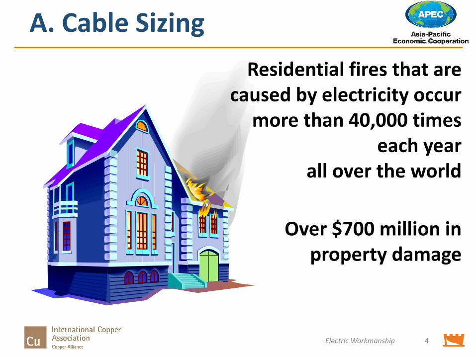
Residential fires that are caused by electricity occur
more than 40,000 times each year
all over the world
Over $700 million in property damage
A. Cable Sizing
A. Cable Sizing
Electric Workmanship 5
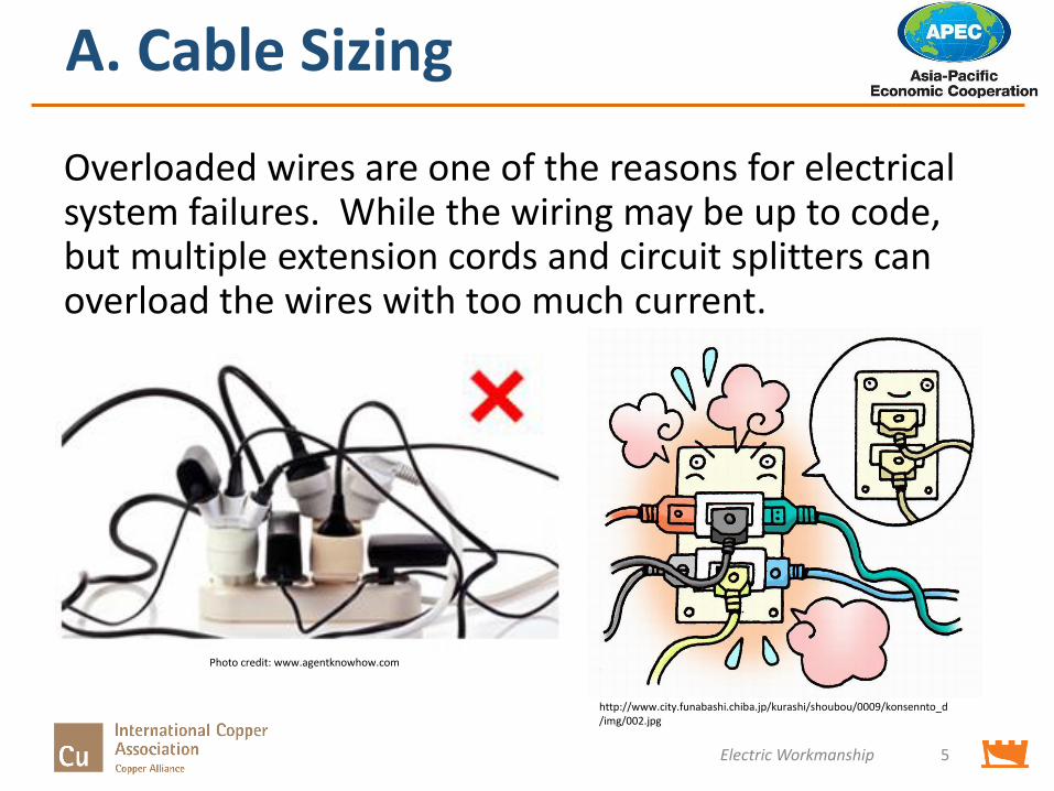
Overloaded wires are one of the reasons for electrical system failures. While the wiring may be up to code, but multiple extension cords and circuit splitters can overload the wires with too much current.
http://www.city.funabashi.chiba.jp/kurashi/shoubou/0009/konsennto_d/img/002.jpg
Photo credit: www.agentknowhow.com
B. Drip Loop
• What is a Drip Loop?
Electric Workmanship 6
B. Drip Loop
• What is a Drip Loop?
Electric Workmanship 7
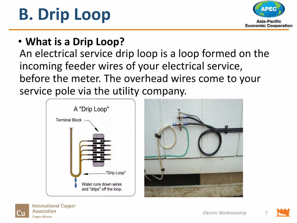
An electrical service drip loop is a loop formed on the incoming feeder wires of your electrical service, before the meter. The overhead wires come to your service pole via the utility company.
B. Drip Loop
• What Purpose Does It Serve?
Electric Workmanship 8
B. Drip Loop
• What Purpose Does It Serve?
Electric Workmanship 9
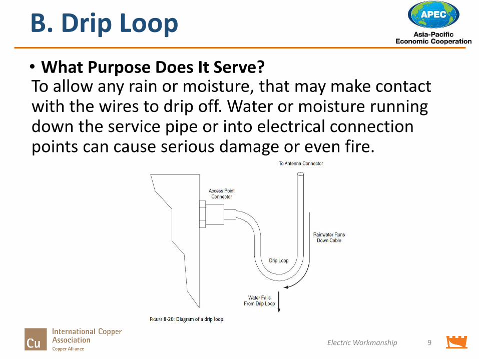
To allow any rain or moisture, that may make contact with the wires to drip off. Water or moisture running down the service pipe or into electrical connection points can cause serious damage or even fire.
C. Surge Protection
• What is surge protection
Electric Workmanship 10
C. Surge Protection
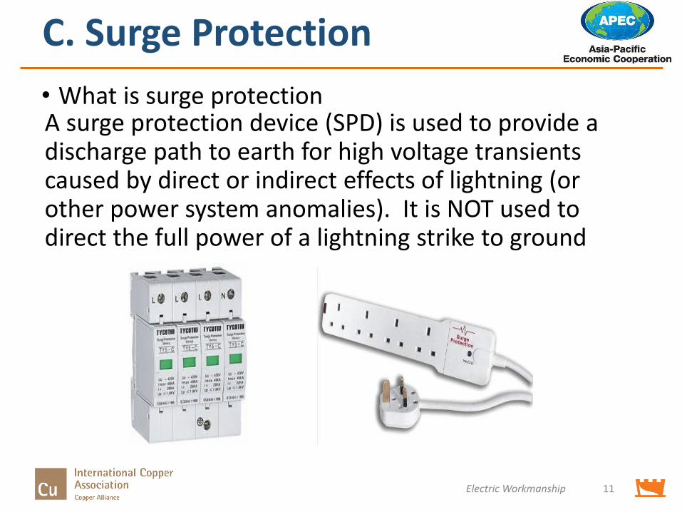
• What is surge protection
Electric Workmanship 11
A surge protection device (SPD) is used to provide a discharge path to earth for high voltage transients caused by direct or indirect effects of lightning (or other power system anomalies). It is NOT used to direct the full power of a lightning strike to ground
C. Surge Protection
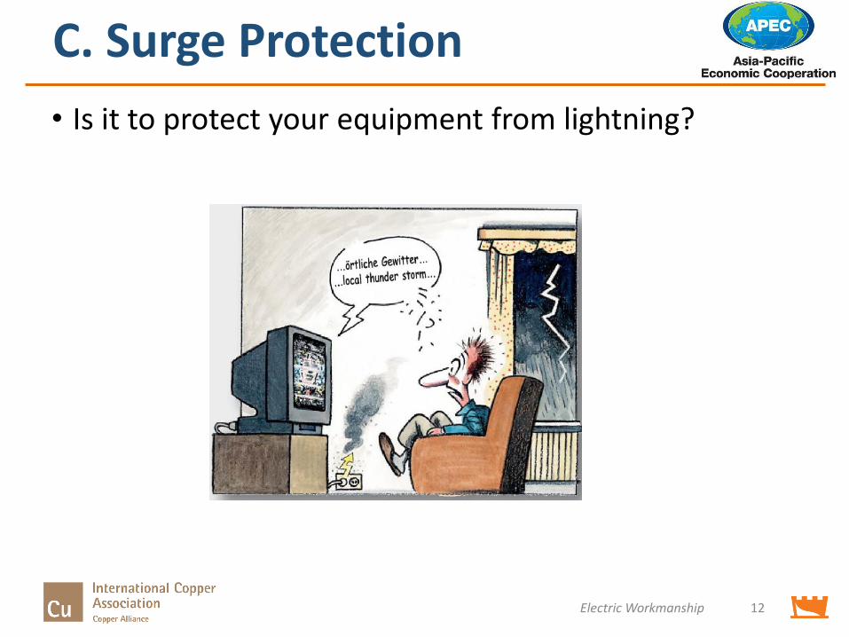
• Is it to protect your equipment from lightning?
Electric Workmanship 12
C. Surge Protection Devices
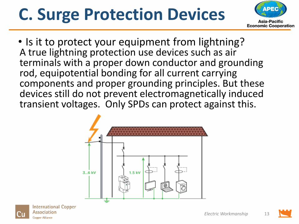
• Is it to protect your equipment from lightning?
Electric Workmanship 13
A true lightning protection use devices such as air terminals with a proper down conductor and grounding rod, equipotential bonding for all current carrying components and proper grounding principles. But these devices still do not prevent electromagnetically induced transient voltages. Only SPDs can protect against this.
D. Lightning Protection
• What is lightning protection?
Electric Workmanship 14
D. Lightning Protection
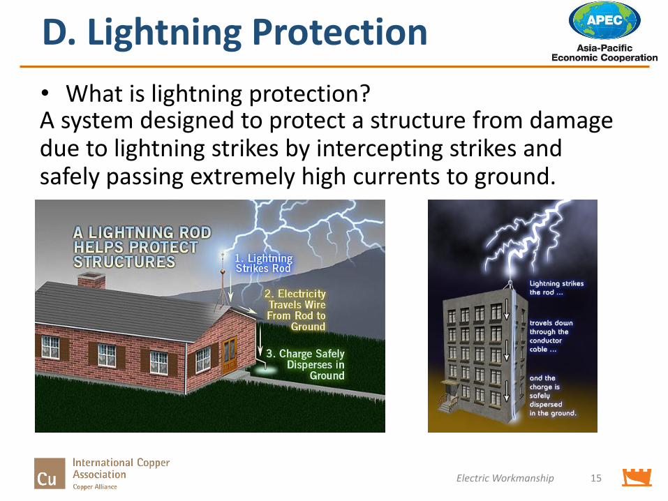
• What is lightning protection?
Electric Workmanship 15
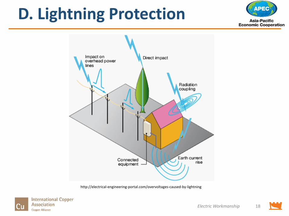
A system designed to protect a structure from damage due to lightning strikes by intercepting strikes and safely passing extremely high currents to ground.
D. Lightning Protection
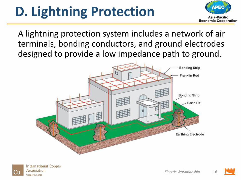
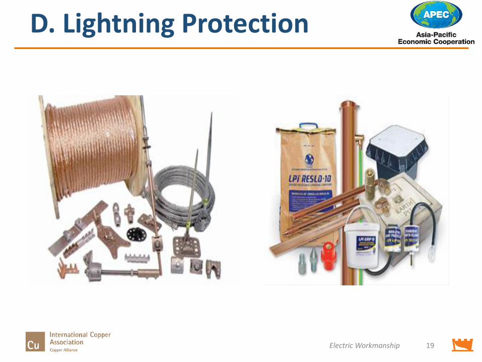
A lightning protection system includes a network of air terminals, bonding conductors, and ground electrodes designed to provide a low impedance path to ground.
Electric Workmanship 16
D. Lightning Protection
Electric Workmanship 17
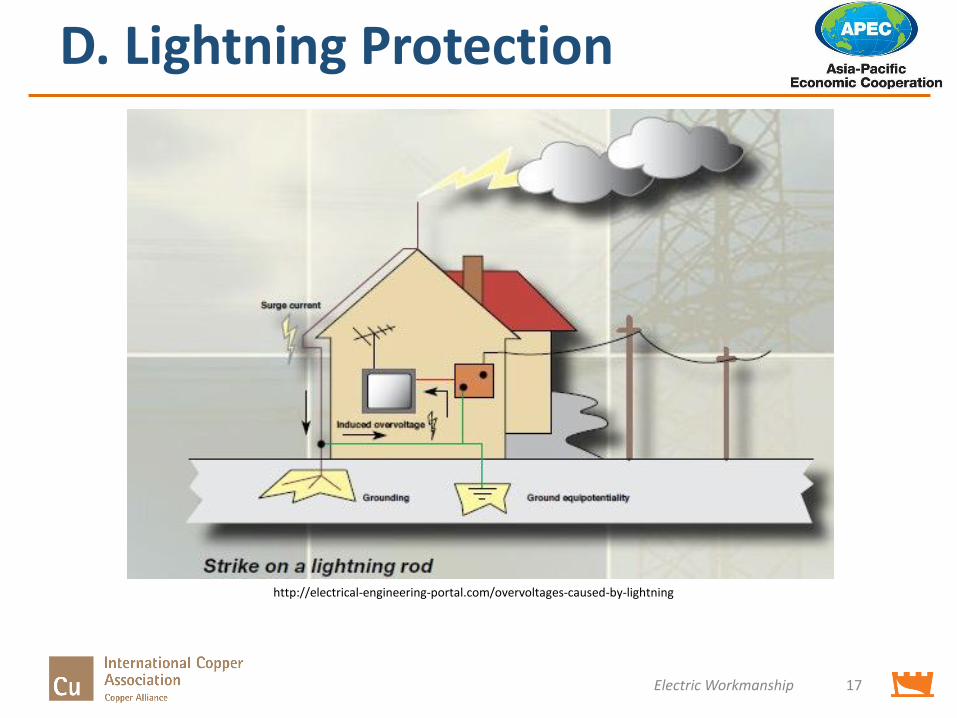
http://electrical-engineering-portal.com/overvoltages-caused-by-lightning
D. Lightning Protection
Electric Workmanship 18
http://electrical-engineering-portal.com/overvoltages-caused-by-lightning
D. Lightning Protection
Electric Workmanship 19
E. Grounding
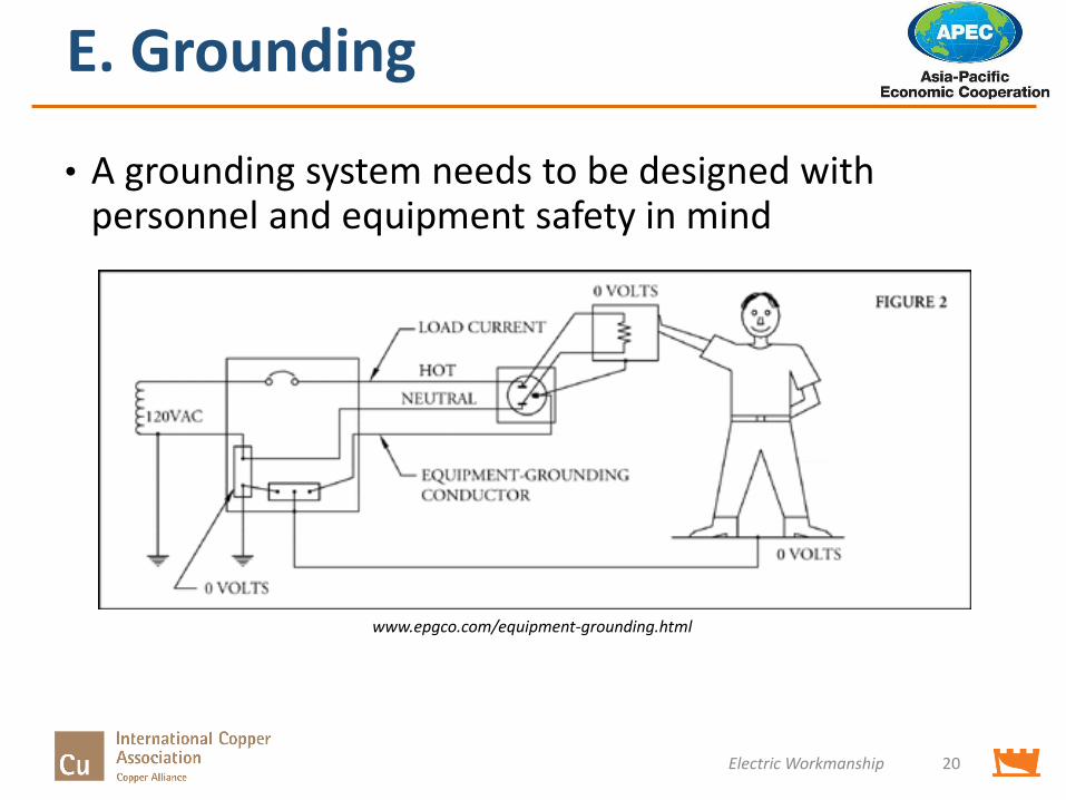
• A grounding system needs to be designed with personnel and equipment safety in mind
Electric Workmanship 20
www.epgco.com/equipment-grounding.html
E. Grounding
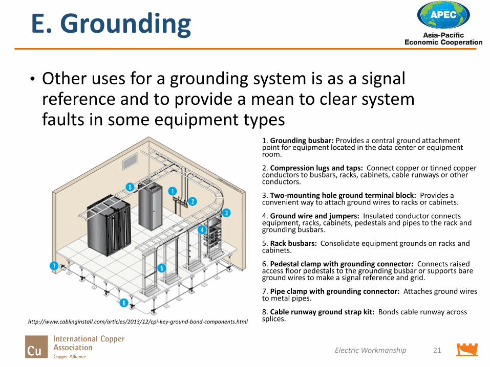
1. Grounding busbar: Provides a central ground attachment point for equipment located in the data center or equipment room.
2. Compression lugs and taps: Connect copper or tinned copper conductors to busbars, racks, cabinets, cable runways or other conductors.
3. Two-mounting hole ground terminal block: Provides a convenient way to attach ground wires to racks or cabinets.
4. Ground wire and jumpers: Insulated conductor connects equipment, racks, cabinets, pedestals and pipes to the rack and grounding busbars.
5. Rack busbars: Consolidate equipment grounds on racks and cabinets.
6. Pedestal clamp with grounding connector: Connects raised access floor pedestals to the grounding busbar or supports bare ground wires to make a signal reference and grid.
7. Pipe clamp with grounding connector: Attaches ground wires to metal pipes.
8. Cable runway ground strap kit: Bonds cable runway across splices.
Electric Workmanship 21
• Other uses for a grounding system is as a signal reference and to provide a mean to clear system faults in some equipment types
http://www.cablinginstall.com/articles/2013/12/cpi-key-ground-bond-components.html
E. Grounding
Electric Workmanship 22
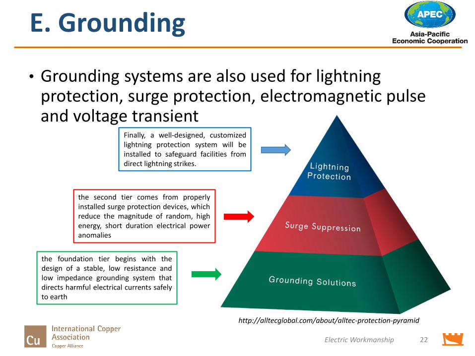
• Grounding systems are also used for lightning protection, surge protection, electromagnetic pulse and voltage transient
the foundation tier begins with thedesign of a stable, low resistance andlow impedance grounding system thatdirects harmful electrical currents safelyto earth
the second tier comes from properlyinstalled surge protection devices, whichreduce the magnitude of random, highenergy, short duration electrical poweranomalies
Finally, a well-designed, customizedlightning protection system will beinstalled to safeguard facilities fromdirect lightning strikes.
http://alltecglobal.com/about/alltec-protection-pyramid
E. Grounding
Electric Workmanship 23
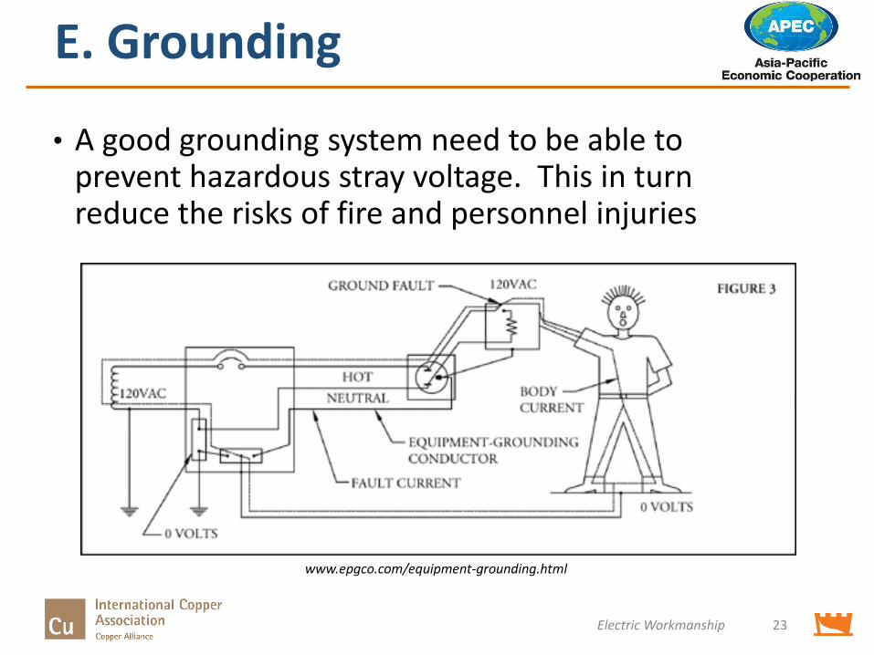
www.epgco.com/equipment-grounding.html
• A good grounding system need to be able to prevent hazardous stray voltage. This in turn reduce the risks of fire and personnel injuries
Electric Workmanship 24
E. Grounding
E. Grounding
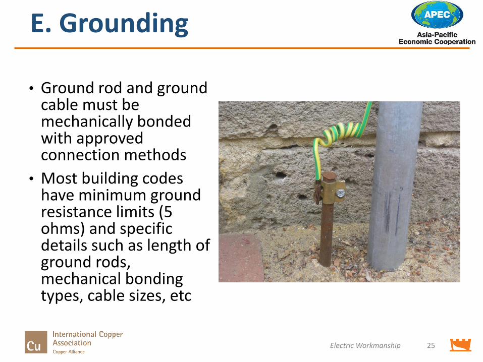
• Ground rod and ground cable must be mechanically bonded with approved connection methods
• Most building codes have minimum ground resistance limits (5 ohms) and specific details such as length of ground rods, mechanical bonding types, cable sizes, etc
Electric Workmanship 25
Workmanship Checklist
Electric Workmanship 26
• A checklist needs to be developed for each local area based on safety codes and local requirements
• This workmanship checklist should cover specific workmanship details related to the installation, operation and maintenance of the system
• A good starting point is to look through local and national requirements and develop the checklist from these documents. Often they already contain compliance checklists
Workmanship Checklist
Electric Workmanship 27
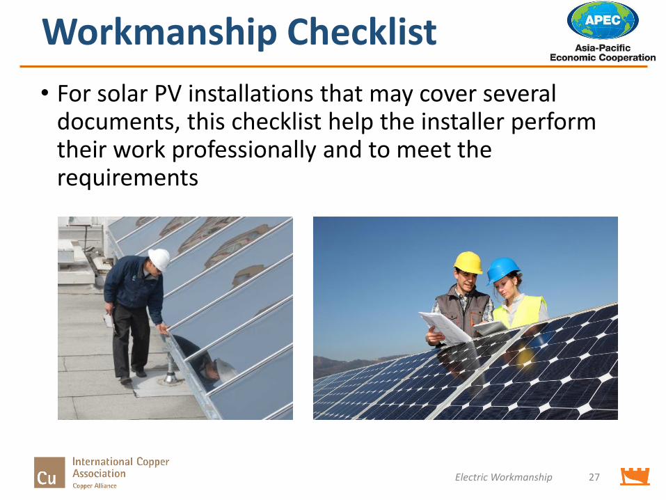
• For solar PV installations that may cover several documents, this checklist help the installer perform their work professionally and to meet the requirements
Sample Workmanship Checklist
Electric Workmanship 28
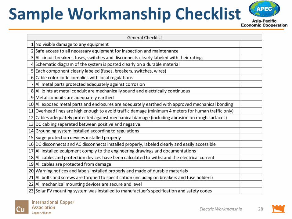
1 No visible damage to any equipment
2 Safe access to all necessary equipment for inspection and maintenance
3 All circuit breakers, fuses, switches and disconnects clearly labeled with their ratings
4 Schematic diagram of the system is posted clearly on a durable material
5 Each component clearly labeled (fuses, breakers, switches, wires)
6 Cable color code complies with local regulations
7 All metal parts protected adequately against corrosion
8 All joints at metal conduit are mechanically sound and electrically continuous
9 Metal conduits are adequately earthed
10 All exposed metal parts and enclosures are adequately earthed with approved mechanical bonding
11 Overhead lines are high enough to avoid traffic damage (minimum 4 meters for human traffic only)
12 Cables adequately protected against mechanical damage (including abrasion on rough surfaces)
13 DC cabling separated between positive and negative
14 Grounding system installed according to regulations
15 Surge protection devices installed properly
16 DC disconnects and AC disconnects installed properly, labeled clearly and easily accessible
17 All installed equipment comply to the engineering drawings and documentations
18 All cables and protection devices have been calculated to withstand the electrical current
19 All cables are protected from damage
20 Warning notices and labels installed properly and made of durable materials
21 All bolts and screws are torqued to specification (including on breakers and fuse holders)
22 All mechanical mounting devices are secure and level
23 Solar PV mounting system was installed to manufactuer's specification and safety codes
General Checklist
Sample Workmanship Checklist
Electric Workmanship 29
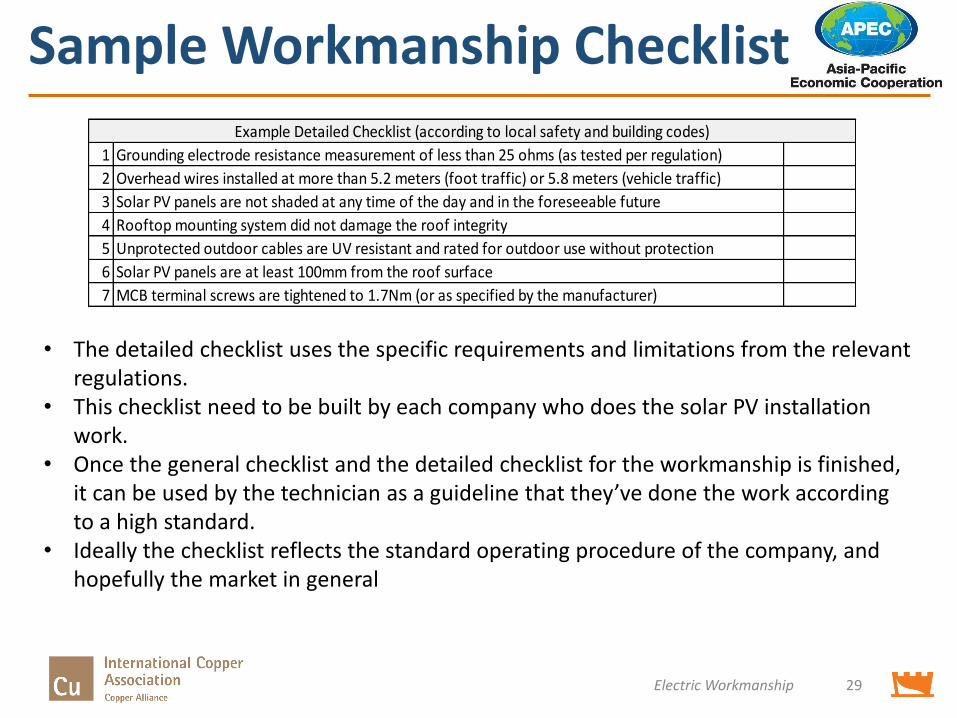
1 Grounding electrode resistance measurement of less than 25 ohms (as tested per regulation)
2 Overhead wires installed at more than 5.2 meters (foot traffic) or 5.8 meters (vehicle traffic)
3 Solar PV panels are not shaded at any time of the day and in the foreseeable future
4 Rooftop mounting system did not damage the roof integrity
5 Unprotected outdoor cables are UV resistant and rated for outdoor use without protection
6 Solar PV panels are at least 100mm from the roof surface
7 MCB terminal screws are tightened to 1.7Nm (or as specified by the manufacturer)
Example Detailed Checklist (according to local safety and building codes)
• The detailed checklist uses the specific requirements and limitations from the relevant regulations.
• This checklist need to be built by each company who does the solar PV installation work.
• Once the general checklist and the detailed checklist for the workmanship is finished, it can be used by the technician as a guideline that they’ve done the work according to a high standard.
• Ideally the checklist reflects the standard operating procedure of the company, and hopefully the market in general

Project Number : EWG 22/2013A
Produced By
Andre SusantoChitra PriambodoCastlerock Consulting - http://www.castlerockasia.com/
ForAsia Pacific Economic Cooperation Secretariat35 Heng Mui Keng TerraceSingapore 119616Tel: (65) 68919 600Fax: (65) 68919 690Email: [email protected]: www.apec.org
© 2015 APEC Secretariat
APEC#215-RE-03.4


