www.rosemount.com ¢00825-0100-46908¤ Quick Installation Guide 00825-0100-4690, Rev CA January 2009 Rosemount 2088 and 2090 Start End Step 1: Mount the Transmitter Step 2: Set the Jumpers Step 3: Connect the Wiring and Power Step 4: Verify Configuration Step 5: Trim the Transmitter Product Certifications Rosemount 2088, 2090P and 2090F Pressure Transmitters
Transcript
www.rosemount.com
¢00825-0100-46908¤
Quick Installation Guide00825-0100-4690, Rev CA
January 2009 Rosemount 2088 and 2090
Start
End
Step 1: Mount the Transmitter
Step 2: Set the Jumpers
Step 3: Connect the Wiring and Power
Step 4: Verify Configuration
Step 5: Trim the Transmitter
Product Certifications
Rosemount 2088, 2090P and 2090F Pressure Transmitters
4690 Rev CA.fm Page 1 Monday, January 19, 2009 11:10 AM
Quick Installation Guide00825-0100-4690, Rev CA
January 2009Rosemount 2088 and 2090
4690 Rev CA.fm Page 2 Monday, January 19, 2009 11:10 AM
Emerson Process Management Asia Pacific Private Limited1 Pandan CrescentSingapore 128461T (65) 6777 8211F (65) 6777 0947/65 6777 0743
Beijing Rosemount Far East Instrument Co., LimitedNo. 6 North Street, Hepingli, Dong Cheng DistrictBeijing 100013, ChinaT (86) (10) 6428 2233F (86) (10) 6422 8586
IMPORTANT NOTICE
This installation guide provides basic guidelines for the Rosemount 2088 and 2090
transmitters. It does not provide instructions for configuration, diagnostics, maintenance,
service, troubleshooting, Explosion-proof, Flameproof, or intrinsically safe (I.S.)
installations.
Refer to the Rosemount 2088/2090 reference manual (document number
00809-0100-4690) for more instruction and low power output. This manual is also
available electronically on www.rosemount.com.
WARNING
Explosions could result in death or serious injury:
Installation of this transmitter in an explosive environment must be in accordance with the
appropriate local, national, and international standards, codes, and practices. Please
review the approvals section of the Rosemount 2088/2090 manual for any restrictions
associated with a safe installation.
• Before connecting a HART-based communicator in an explosive atmosphere, make
sure the instruments in the loop are installed in accordance with intrinsically safe or
non-incendive field wiring practices.
• In an Explosion-proof/Flameproof installation, do not remove the transmitter covers
when power is applied to the unit.
Process leaks may cause harm or result in death
• Use appropriately rated sanitary clamps and gaskets during installation.
• The maximum working pressure of the clamp and gasket must be greater than or
equal to the working pressure range of the transmitter.
Electrical shock can result in death or serious injury
• Avoid contact with the leads and terminals. High voltage that may be present on leads
can cause electrical shock.
2
Quick Installation Guide00825-0100-4690, Rev CA
January 2009 Rosemount 2088 and 2090
4690 Rev CA.fm Page 3 Monday, January 19, 2009 11:10 AM
STEP 1: MOUNT THE TRANSMITTER
Rosemount 2088
Mount directly to the impulse line without using an additional mounting bracket or mount
directly to a wall, panel, or two-inch pipe using an optional mounting bracket.
Rosemount 2090P
Mount directly to the process pipe using an existing weld spud, or have a skilled welder install a new weld spud using a TIG welder. Improper installation may result in weld spud distortion. Recommended mounting in upright or horizontal position to allow proper draining of vent.
Rosemount 2090F
Mount directly to the process pipe using a standard sanitary fitting (either a 1.5- or 2-inch
Tri-Clamp connection). Recommended mounting in upright or horizontal position to allow
proper draining of vent.
Do not apply torque directly to the electronics housing. To avoid damage, apply torque only to the hex-shaped process connection.
2088 2090P 2090F
Panel Mount Pipe Mount
1/2–14
NPT FemaleProcess
Connection
VesselWall
WeldSpud
1.5 in. 1.0 in.
O-ringVesselWall 1
1/2 or 2-in.
Tri-Clamp Connection
3
Quick Installation Guide00825-0100-4690, Rev CA
January 2009Rosemount 2088 and 2090
4690 Rev CA.fm Page 4 Monday, January 19, 2009 11:10 AM
STEP 1 CONTINUED...
Liquid Flow Applications
1. Place taps to the side of the line.
2. Mount beside or below the taps.
Gas Flow Applications
1. Place taps in the top or side of the line.
2. Mount level or above the taps.
Steam Flow Applications
1. Place taps to the side of the line.
2. Mount beside or below the taps.
3. Fill impulse lines with water.
4
Quick Installation Guide00825-0100-4690, Rev CA
January 2009 Rosemount 2088 and 2090
4690 Rev CA.fm Page 5 Monday, January 19, 2009 11:10 AM
STEP 2: SET THE JUMPERS
If alarm and security jumpers are not installed, the transmitter will operate normally with the
default alarm condition alarm high and the security off.
1. If the transmitter is installed, secure the loop, and remove power.
2. Remove the housing cover opposite the field terminal side. Do not remove the
instrument cover in explosive atmospheres when the circuit is live.
3. Reposition the jumper. Avoid contact with the leads and the terminals. See Figure 1 for
the location of the jumper and the ON and OFF positions.
4. Reattach the transmitter cover. The cover must be fully engaged to comply with
explosion-proof requirements.
Figure 1. 2088 Transmitter Electronics Board
Without LCD Display With LCD Display
Low Power without LCD Display Low Power with LCD Display
Security
Alarm
Security
Alarm
Alarm
Security
Alarm
Security
5
Quick Installation Guide00825-0100-4690, Rev CA
January 2009Rosemount 2088 and 2090
4690 Rev CA.fm Page 6 Monday, January 19, 2009 11:10 AM
6
STEP 3: CONNECT THE WIRING AND POWER
Use the following steps to wire the transmitter:
1. Remove the housing cover on the side marked FIELD TERMINALS.
2. Connect the positive lead to the “PWR/COMM+” terminal, and the negative lead to the
“–” terminal.
NOTE
Do not connect the powered signal wiring to the test terminals. Power could damage the test
diode in the test connection. Twisted pair cable yields best results. For high EMI/RFI
environments, shielded twisted pair cable should be used. Use 24 AWG or larger wire and
do not exceed 5,000 feet (1 500 meters).
3. Plug and seal unused conduit connections.
4. If applicable, install wiring with a drip loop. Arrange the drip loop so the bottom is lower
than the conduit connections and the transmitter housing.
Figure 2 shows wiring connections necessary to power a 2088 or 2090 transmitter and
enable communications with a hand-held HART communicator.
IMPORTANT NOTICE
Figure 2. Bench Hook-up Wiring Diagrams (4–20 mA Transmitters)
Figure 3. Field Wiring for 2088 —Low Power Option Code N
The enclosed pipe plug must be installed in unused conduit opening with a minimum of five thread engagement to comply with explosion-proof requirements. Refer to the 2088/2090 reference manual (document number 00809-0100-4690) for more information. This manual is also available electronically on www.emersonprocess.com/rosemount.
CurrentMeter
24 V dc SupplyRL ≥ 250 � Power SupplyVoltmeter
The signal loop may be grounded at any single point in the loop, or may be left ungrounded.
Quick Installation Guide00825-0100-4690, Rev CA
January 2009 Rosemount 2088 and 2090
4690 Rev CA.fm Page 7 Monday, January 19, 2009 11:10 AM
Power Supply
The dc power supply (Option S:
10.5 - 36 V and Option N: 6 - 14 V)
should provide power with less
than two percent ripple. The total
resistance load is the sum of the
resistance of the signal leads and
the load resistance of the
controller, indicator, and related
pieces. The resistance of intrinsic
safety barriers, if used, must be
included
Figure 4. Load Limitations (4 — 20 mA transmitters)
Lo
ad
(o
hm
s)
Operating Region
Power Supply Output Code S (dc Volts)
Communication requires a minimum loop resistance of 250 ohms.(1) For hazardous location approvals, power supply must not exceed 36 V.(2) For CENELEC Ex ia approval, the power supply must not exceed 30 V.
Max. Loop Resistance = 43.5 (Power Supply Voltage – 10.5)
7
Quick Installation Guide00825-0100-4690, Rev CA
January 2009Rosemount 2088 and 2090
4690 Rev CA.fm Page 8 Monday, January 19, 2009 11:10 AM
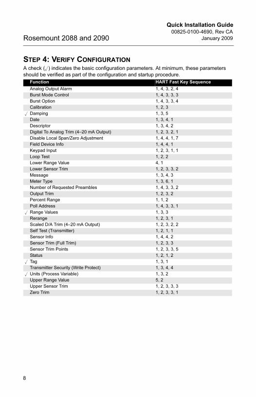
STEP 4: VERIFY CONFIGURATION
A check (�) indicates the basic configuration parameters. At minimum, these parameters
should be verified as part of the configuration and startup procedure.
Function HART Fast Key Sequence
Analog Output Alarm 1, 4, 3, 2, 4
Burst Mode Control 1, 4, 3, 3, 3
Burst Option 1, 4, 3, 3, 4
Calibration 1, 2, 3
� Damping 1, 3, 5
Date 1, 3, 4, 1
Descriptor 1, 3, 4, 2
Digital To Analog Trim (4–20 mA Output) 1, 2, 3, 2, 1
Disable Local Span/Zero Adjustment 1, 4, 4, 1, 7
Field Device Info 1, 4, 4, 1
Keypad Input 1, 2, 3, 1, 1
Loop Test 1, 2, 2
Lower Range Value 4, 1
Lower Sensor Trim 1, 2, 3, 3, 2
Message 1, 3, 4, 3
Meter Type 1, 3, 6, 1
Number of Requested Preambles 1, 4, 3, 3, 2
Output Trim 1, 2, 3, 2
Percent Range 1, 1, 2
Poll Address 1, 4, 3, 3, 1
� Range Values 1, 3, 3
Rerange 1, 2, 3, 1
Scaled D/A Trim (4–20 mA Output) 1, 2, 3, 2, 2
Self Test (Transmitter) 1, 2, 1, 1
Sensor Info 1, 4, 4, 2
Sensor Trim (Full Trim) 1, 2, 3, 3
Sensor Trim Points 1, 2, 3, 3, 5
Status 1, 2, 1, 2
� Tag 1, 3, 1
Transmitter Security (Write Protect) 1, 3, 4, 4
� Units (Process Variable) 1, 3, 2
Upper Range Value 5, 2
Upper Sensor Trim 1, 2, 3, 3, 3
Zero Trim 1, 2, 3, 3, 1
8
Quick Installation Guide00825-0100-4690, Rev CA
January 2009 Rosemount 2088 and 2090
4690 Rev CA.fm Page 9 Monday, January 19, 2009 11:10 AM
STEP 5: TRIM THE TRANSMITTER
NOTE
Transmitters are shipped from Rosemount Inc. fully calibrated to user specified range or by
the factory default of full scale.
Zero Trim
A zero trim is a single-point adjustment used for compensating mounting position effects. If
zero offset is less than 3% of true zero, follow the “Using the HART Communicator”
instructions below. If zero offset is greater than 3% of true zero, follow the “Using the
Transmitter Zero Adjustment Button” instructions below to rerange.
Using the HART Communicator
Using the Transmitter Zero Adjustment Button
Fast Keys Steps
1, 2, 3, 3, 1 1. Vent the transmitter and connect HART communicator.2. At the menu, input the HART Fast Key sequence.
3. Follow the commands to perform a zero trim.
1. Loosen the certifications label screw and rotate the label to
expose the zero adjustment button.
2. Apply the desired pressure for the 4 mA output.
3. Set the 4 mA point by pressing the zero button for 2 seconds.
Verify that the output is 4 mA. The optional LCD will display
ZERO PASS.
Zero Adjustment Button
9
Quick Installation Guide00825-0100-4690, Rev CA
January 2009Rosemount 2088 and 2090
4690 Rev CA.fm Page 10 Monday, January 19, 2009 11:10 AM
PRODUCT CERTIFICATIONS
Approved Manufacturing Locations
Rosemount Inc. — Chanhassen, Minnesota, USA
Fisher-Rosemount GmbH & Co. — Wessling, Germany
Emerson Process Management Asia Pacific Private Limited — Singapore
Beijing Rosemount Far East Instrument Co., LTD — Beijing, China
European Union Directive Information
The EC declaration of conformity for all applicable European directives for this product can
be found on the Rosemount website at www.rosemount.com. A hard copy may be obtained
by contacting our local sales office.
ATEX Directive (94/9/EC)
Emerson Process Management complies with the ATEX Directive.
European Pressure Equipment Directive (PED) (97/23/EC)
Model 2088/2090 Pressure Transmitters
— Sound Engineering Practice
Electro Magnetic Compatibility (EMC) (89/336/EEC)
All Model 2088/2090 Smart Pressure Transmitter:
EN 50081-1: 1992; EN 50082-2:1995; EN 61326-1:1997
Hazardous Locations Certifications
North American Certifications
Factory Mutual (FM)
E5 Explosion-proof for Class I, Division 1, Groups B, C, and D. Dust-Ignition-Proof for Class
II, Division 1, Groups E, F, G, Class III, Division 1, indoor and outdoor (NEMA 4X)
hazardous locations; factory sealed. Temperature Class T5 Ta = 85 °C.
I5 Intrinsically safe for use in Class I, Division 1, Groups A, B, C, D; Class II, Division 1,
Groups E, F, and G; and Class III, Division 1 when connected in accordance with
Rosemount drawing 02088-1018. Non-incendive for Class I, Division 2, Groups A, B,
C, and D. Temperature Class T4 Ta = 85 °C; indoor and outdoor (NEMA 4X)
hazardous locations.
For input parameters see control drawing 02088-1018.
Canadian Standards Association (CSA)
All CSA hazardous approved transmitters are certified per ANSI/ISA 12.27.01-2003.
C6 Explosion-proof for Class I, Division 1, Groups B, C, and D. Dust-Ignition-Proof for
Class II, Division 1, Groups E, F, G, Class III, indoor and outdoor hazardous locations.
CSA enclosure Type 4X; factory sealed. Suitable for Class I, Division 2, Groups A, B,
C, and D. Single Seal.
Intrinsically Safe for Class I, Division 1, Groups A, B, C, and D. Temp. Code T3C.
Intrinsically safe when connected with approved barriers in accordance with
Rosemount drawing 02088-1024. Single Seal.
For input parameters see control drawing 02088-1024.
10
Quick Installation Guide00825-0100-4690, Rev CA
January 2009 Rosemount 2088 and 2090
4690 Rev CA.fm Page 11 Monday, January 19, 2009 11:10 AM
European Certifications
I1 BASEEFA ATEX Intrinsic Safety
Certificate No.: BAS00ATEX1166X II 1 G
Ex ia IIC T5 (Tamb = –55 to 40 °C)
Ex ia IIC T4 (Tamb = –55 to 70°C)
1180
Table 1. Input Parameters
Special Conditions for Safe Use (x):
When the optional transient protection terminal block is installed, the apparatus is not
capable of withstanding a 500V rms test to case. This must be taken into account on
any installation in which it is used, for example by assuring that the supply to the
apparatus is galvanically isolated.
N1 BASEEFA ATEX Type n
Certification No.: BAS00ATEX3167X II 3 G
Ex nA nL IIC T5 (Ta = -40 °C to 70 °C)
Ui = 50 V dc max
Special Conditions for Safe Use (x):
When the optional transient protection terminal block is installed, the apparatus is not
capable of withstanding a 500 V r.m.s. test to case. This must be taken into account
on any installation in which it is used, for example, by assuring that the supply to the
apparatus is galvanically isolated.
ND BASEEFA ATEX Dust
Certificate No.: BAS01ATEX1427X II 1 D
Ex tD A20 T105°C (Tamb = -20°C to 85°C)
IP66
1180
Vmax = 36 V dc
Special Conditions for Safe Use (x):
1. The user must ensure that the maximum rated voltage and current (36 volts, 24 mA,
D.C.) are not exceeded. All connections to other apparatus or associated apparatus
shall have control over this voltage and current equivalent to a category “ib” circuit
according to EN50020.
2. Cable entries must be used which maintain the ingress protection of the enclosure
to at least IP66.
3. Unused cable entries must be filled with suitable blanking plugs which maintain the
ingress protection of the enclosure to at least IP66.
4. Cable entries and blanking plugs must be suitable for the ambient range of the
apparatus and capable of withstanding a 7J impact test.
5. The 2088/2090 sensor module must be securely screwed in place to maintain the
ingress protection of the enclosure.
Loop/Power Input Type
Ui = 30 V dc Smart
Ii = 200 mA Smart
Pi = 0.9 W Smart
Ci = 0.012 �F Smart
11
Quick Installation Guide00825-0100-4690, Rev CA
January 2009Rosemount 2088 and 2090
4690 Rev CA.fm Page 12 Monday, January 19, 2009 11:10 AM
ED KEMA ATEX Flameproof
Certification No.: KEMA97ATEX2378 II 1/2 G
Ex d IIC T6 (Ta = -20 °C to 40°C)
T4 (Ta = -20 °C to 80 °C)
1180
Vmax = 36 (with Smart output option)
Vmax = 14 (with low power output option)
E7 KEMA IECEx Flameproof
Certification No.: IECEx KEM 06.0021
Ex d IIC T4 (Tamb = -40°C to 80°C)
1180
Vmax = 36 (with Smart output option)
Vmax = 14 (with low power output option)
Japanese Certifications
E4 TIIS Flameproof
Ex d IIC T6 (Tamb = 85 °C)
Brazil Certifications
I2 INMETRO Intrinsic Safety
Certification No.: CEPEL-Ex-063/97-1X
BR-Ex ia IIC T5/T4
E2 INMETRO Flameproof (2088 Series only)
Certification No.: CEPEL-Ex-076/97-1
BR-Ex d IIC T6/T5
Combinations of Certifications
Stainless steel certification tag is provided when optional approval is specified. Once a
device labeled with multiple approval types is installed, it should not be reinstalled using any
other approval types. Permanently mark the approval label to distinguish it from unused
approval types.
KB K5 and C6 combination
KH K5, ED and I1 combination
K5 E5 and I5 combination
Certificate Description
C15875 2088 Smart with SST wetted parts (no display)
C15879 2088 Smart with SST wetted parts (with display)
C15876 2088 Smart with Alloy C-276 wetted parts (no display)
C15877 2088 Smart with Alloy C-276 wetted parts (with display)
C15871 2088 Smart with SST CR option (no display)
C15873 2088 Smart with Alloy C-276 CR option (no display)
C15872 2088 Smart with SST CR option (with display)
C15874 2088 Smart with Alloy C-276 CR option (with display)