184
Reference Manual 00809-0100-2410, Rev DA March 2017 Rosemount ™ 2410 Tank Hub

Reference Manual00809-0100-2410, Rev DA
March 2017
Rosemount™ 2410 Tank Hub

Reference Manual 00809-0100-2410, Rev DA
Title PageMarch 2017
Rosemount™ 2410 Tank Hub
NOTICE
Read this manual before working with the product. For personal and system safety, and for optimum product performance, make sure you thoroughly understand the contents before installing, using, or maintaining this product.
For equipment service or support needs, contact your local Emerson™ Automation Solutions/Rosemount Tank Gauging representative.
Spare PartsAny substitution of non-recognized spare parts may jeopardize safety. Repair, e.g. substitution of components etc, may also jeopardize safety and is under no circumstances allowed.
Rosemount Tank Radar AB will not take any responsibility for faults, accidents, etc caused by non-recognized spare parts or any repair which is not made by Rosemount Tank Radar AB.
The products described in this document are NOT designed for nuclear-qualified applications.
Using non-nuclear qualified products in applications that require nuclear-qualified hardware or products may cause inaccurate readings.
For information on Rosemount nuclear-qualified products, contact your local Rosemount Sales Representative.
WARNING - Substitution of components may impair Intrinsic Safety.
WARNING - To prevent ignition of flammable or combustible atmospheres, disconnect power before servicing.
AVERTISSEMENT - La substitution de composants peut compromettre la sécurité intrinsèque.
AVERTISSEMENT - Ne pas ouvrir en cas de presence d'atmosphere explosive.
iTitle Page

Reference Manual00809-0100-2410, Rev DA
Title PageMarch 2017
ii Title Page
Reference Manual 00809-0100-2410, Rev DA
ContentsMarch 2017
Contents
1Section 1: Introduction1.1 Safety messages. . . . . . . . . . . . . . . . . . . . . . . . . . . . . . . . . . . . . . . . . . . . . . . . . . . . . . . . . . . . . . . . . . . 1
1.2 Symbols . . . . . . . . . . . . . . . . . . . . . . . . . . . . . . . . . . . . . . . . . . . . . . . . . . . . . . . . . . . . . . . . . . . . . . . . . . 2
1.3 Manual overview . . . . . . . . . . . . . . . . . . . . . . . . . . . . . . . . . . . . . . . . . . . . . . . . . . . . . . . . . . . . . . . . . . 3
1.4 Technical documentation . . . . . . . . . . . . . . . . . . . . . . . . . . . . . . . . . . . . . . . . . . . . . . . . . . . . . . . . . . 4
1.5 Service support. . . . . . . . . . . . . . . . . . . . . . . . . . . . . . . . . . . . . . . . . . . . . . . . . . . . . . . . . . . . . . . . . . . . 5
1.6 Product recycling/disposal. . . . . . . . . . . . . . . . . . . . . . . . . . . . . . . . . . . . . . . . . . . . . . . . . . . . . . . . . . 5
1.7 Packing material . . . . . . . . . . . . . . . . . . . . . . . . . . . . . . . . . . . . . . . . . . . . . . . . . . . . . . . . . . . . . . . . . . 5
1.7.1 Reuse and recycling . . . . . . . . . . . . . . . . . . . . . . . . . . . . . . . . . . . . . . . . . . . . . . . . . . . . . . . . . . 5
1.7.2 Energy recovery . . . . . . . . . . . . . . . . . . . . . . . . . . . . . . . . . . . . . . . . . . . . . . . . . . . . . . . . . . . . . 5
2Section 2: Overview2.1 Introduction . . . . . . . . . . . . . . . . . . . . . . . . . . . . . . . . . . . . . . . . . . . . . . . . . . . . . . . . . . . . . . . . . . . . . . 7
2.1.1 Communication . . . . . . . . . . . . . . . . . . . . . . . . . . . . . . . . . . . . . . . . . . . . . . . . . . . . . . . . . . . . . 9
2.2 Components . . . . . . . . . . . . . . . . . . . . . . . . . . . . . . . . . . . . . . . . . . . . . . . . . . . . . . . . . . . . . . . . . . . . . 11
2.3 System overview . . . . . . . . . . . . . . . . . . . . . . . . . . . . . . . . . . . . . . . . . . . . . . . . . . . . . . . . . . . . . . . . . 12
2.4 Installation procedure. . . . . . . . . . . . . . . . . . . . . . . . . . . . . . . . . . . . . . . . . . . . . . . . . . . . . . . . . . . . . 19
3Section 3: Installation3.1 Safety messages. . . . . . . . . . . . . . . . . . . . . . . . . . . . . . . . . . . . . . . . . . . . . . . . . . . . . . . . . . . . . . . . . . 21
3.2 Installation considerations . . . . . . . . . . . . . . . . . . . . . . . . . . . . . . . . . . . . . . . . . . . . . . . . . . . . . . . . . 22
3.3 Mechanical installation . . . . . . . . . . . . . . . . . . . . . . . . . . . . . . . . . . . . . . . . . . . . . . . . . . . . . . . . . . . . 23
3.3.1 Pipe mounting . . . . . . . . . . . . . . . . . . . . . . . . . . . . . . . . . . . . . . . . . . . . . . . . . . . . . . . . . . . . . 23
3.3.2 Wall mounting . . . . . . . . . . . . . . . . . . . . . . . . . . . . . . . . . . . . . . . . . . . . . . . . . . . . . . . . . . . . . 24
iiiContents
Reference Manual00809-0100-2410, Rev DA
ContentsMarch 2017
3.4 Electrical installation . . . . . . . . . . . . . . . . . . . . . . . . . . . . . . . . . . . . . . . . . . . . . . . . . . . . . . . . . . . . . . 25
3.4.1 Cable entries . . . . . . . . . . . . . . . . . . . . . . . . . . . . . . . . . . . . . . . . . . . . . . . . . . . . . . . . . . . . . . . 25
3.4.2 Power supply . . . . . . . . . . . . . . . . . . . . . . . . . . . . . . . . . . . . . . . . . . . . . . . . . . . . . . . . . . . . . . . 25
3.4.3 Cable selection for power supply. . . . . . . . . . . . . . . . . . . . . . . . . . . . . . . . . . . . . . . . . . . . . . 26
3.4.4 Grounding . . . . . . . . . . . . . . . . . . . . . . . . . . . . . . . . . . . . . . . . . . . . . . . . . . . . . . . . . . . . . . . . . 26
3.4.5 Cable selection for the Tankbus. . . . . . . . . . . . . . . . . . . . . . . . . . . . . . . . . . . . . . . . . . . . . . . 27
3.4.6 Power budget . . . . . . . . . . . . . . . . . . . . . . . . . . . . . . . . . . . . . . . . . . . . . . . . . . . . . . . . . . . . . . 28
3.4.7 Tankbus . . . . . . . . . . . . . . . . . . . . . . . . . . . . . . . . . . . . . . . . . . . . . . . . . . . . . . . . . . . . . . . . . . . 29
3.4.8 Typical installations . . . . . . . . . . . . . . . . . . . . . . . . . . . . . . . . . . . . . . . . . . . . . . . . . . . . . . . . . 36
3.4.9 Cabling for the TRL2/RS485 Bus . . . . . . . . . . . . . . . . . . . . . . . . . . . . . . . . . . . . . . . . . . . . . . 43
3.4.10Non-IS connection . . . . . . . . . . . . . . . . . . . . . . . . . . . . . . . . . . . . . . . . . . . . . . . . . . . . . . . . . . 45
3.4.11Non-IS terminal block . . . . . . . . . . . . . . . . . . . . . . . . . . . . . . . . . . . . . . . . . . . . . . . . . . . . . . . 49
3.4.12IS connection . . . . . . . . . . . . . . . . . . . . . . . . . . . . . . . . . . . . . . . . . . . . . . . . . . . . . . . . . . . . . . 52
3.4.13Intrinsically safe terminal block . . . . . . . . . . . . . . . . . . . . . . . . . . . . . . . . . . . . . . . . . . . . . . . 53
3.4.14Wiring diagrams . . . . . . . . . . . . . . . . . . . . . . . . . . . . . . . . . . . . . . . . . . . . . . . . . . . . . . . . . . . . 55
4Section 4: Configuration4.1 Safety messages. . . . . . . . . . . . . . . . . . . . . . . . . . . . . . . . . . . . . . . . . . . . . . . . . . . . . . . . . . . . . . . . . . 59
4.2 Introduction . . . . . . . . . . . . . . . . . . . . . . . . . . . . . . . . . . . . . . . . . . . . . . . . . . . . . . . . . . . . . . . . . . . . . 60
4.3 Configuration tools . . . . . . . . . . . . . . . . . . . . . . . . . . . . . . . . . . . . . . . . . . . . . . . . . . . . . . . . . . . . . . . 60
4.4 Basic configuration of a Rosemount 2410 Tank Hub . . . . . . . . . . . . . . . . . . . . . . . . . . . . . . . . . . 61
4.5 Advanced configuration . . . . . . . . . . . . . . . . . . . . . . . . . . . . . . . . . . . . . . . . . . . . . . . . . . . . . . . . . . . 62
4.6 Configuration using TankMaster WinSetup . . . . . . . . . . . . . . . . . . . . . . . . . . . . . . . . . . . . . . . . . . 62
4.6.1 Installation wizard . . . . . . . . . . . . . . . . . . . . . . . . . . . . . . . . . . . . . . . . . . . . . . . . . . . . . . . . . . 63
4.6.2 Advanced configuration . . . . . . . . . . . . . . . . . . . . . . . . . . . . . . . . . . . . . . . . . . . . . . . . . . . . . 63
4.6.3 Installing a Rosemount 2460 System Hub . . . . . . . . . . . . . . . . . . . . . . . . . . . . . . . . . . . . . . 64
5Section 5: Operation5.1 Safety messages. . . . . . . . . . . . . . . . . . . . . . . . . . . . . . . . . . . . . . . . . . . . . . . . . . . . . . . . . . . . . . . . . . 65
5.2 Integral display . . . . . . . . . . . . . . . . . . . . . . . . . . . . . . . . . . . . . . . . . . . . . . . . . . . . . . . . . . . . . . . . . . . 66
5.3 Start-up information . . . . . . . . . . . . . . . . . . . . . . . . . . . . . . . . . . . . . . . . . . . . . . . . . . . . . . . . . . . . . . 68
5.4 Error messages . . . . . . . . . . . . . . . . . . . . . . . . . . . . . . . . . . . . . . . . . . . . . . . . . . . . . . . . . . . . . . . . . . . 69
5.5 LED . . . . . . . . . . . . . . . . . . . . . . . . . . . . . . . . . . . . . . . . . . . . . . . . . . . . . . . . . . . . . . . . . . . . . . . . . . . . . 70
5.5.1 LED Start-Up information . . . . . . . . . . . . . . . . . . . . . . . . . . . . . . . . . . . . . . . . . . . . . . . . . . . . 71
5.5.2 Error LED. . . . . . . . . . . . . . . . . . . . . . . . . . . . . . . . . . . . . . . . . . . . . . . . . . . . . . . . . . . . . . . . . . . 72
5.6 Specifying display variables . . . . . . . . . . . . . . . . . . . . . . . . . . . . . . . . . . . . . . . . . . . . . . . . . . . . . . . . 74
iv Contents
Reference Manual 00809-0100-2410, Rev DA
ContentsMarch 2017
6Section 6: Service and Troubleshooting6.1 Safety messages. . . . . . . . . . . . . . . . . . . . . . . . . . . . . . . . . . . . . . . . . . . . . . . . . . . . . . . . . . . . . . . . . . 77
6.2 Service . . . . . . . . . . . . . . . . . . . . . . . . . . . . . . . . . . . . . . . . . . . . . . . . . . . . . . . . . . . . . . . . . . . . . . . . . . 78
6.2.1 Viewing Input and Holding registers. . . . . . . . . . . . . . . . . . . . . . . . . . . . . . . . . . . . . . . . . . . 78
6.2.2 Editing Holding registers. . . . . . . . . . . . . . . . . . . . . . . . . . . . . . . . . . . . . . . . . . . . . . . . . . . . . 79
6.2.3 Device Live List . . . . . . . . . . . . . . . . . . . . . . . . . . . . . . . . . . . . . . . . . . . . . . . . . . . . . . . . . . . . . 80
6.2.4 Configuration backup . . . . . . . . . . . . . . . . . . . . . . . . . . . . . . . . . . . . . . . . . . . . . . . . . . . . . . . 82
6.2.5 Configuration recovery . . . . . . . . . . . . . . . . . . . . . . . . . . . . . . . . . . . . . . . . . . . . . . . . . . . . . . 83
6.2.6 Diagnostics . . . . . . . . . . . . . . . . . . . . . . . . . . . . . . . . . . . . . . . . . . . . . . . . . . . . . . . . . . . . . . . . 84
6.2.7 Device firmware upgrade . . . . . . . . . . . . . . . . . . . . . . . . . . . . . . . . . . . . . . . . . . . . . . . . . . . . 85
6.2.8 Write protection . . . . . . . . . . . . . . . . . . . . . . . . . . . . . . . . . . . . . . . . . . . . . . . . . . . . . . . . . . . . 87
6.2.9 Write protection switch . . . . . . . . . . . . . . . . . . . . . . . . . . . . . . . . . . . . . . . . . . . . . . . . . . . . . 88
6.2.10Simulation mode . . . . . . . . . . . . . . . . . . . . . . . . . . . . . . . . . . . . . . . . . . . . . . . . . . . . . . . . . . . 89
6.2.11Testing the relays . . . . . . . . . . . . . . . . . . . . . . . . . . . . . . . . . . . . . . . . . . . . . . . . . . . . . . . . . . . 91
6.2.12Relay output configuration . . . . . . . . . . . . . . . . . . . . . . . . . . . . . . . . . . . . . . . . . . . . . . . . . . 92
6.2.13Loading the default database . . . . . . . . . . . . . . . . . . . . . . . . . . . . . . . . . . . . . . . . . . . . . . . . 93
6.2.14Logging measurement data. . . . . . . . . . . . . . . . . . . . . . . . . . . . . . . . . . . . . . . . . . . . . . . . . . 94
6.3 Troubleshooting . . . . . . . . . . . . . . . . . . . . . . . . . . . . . . . . . . . . . . . . . . . . . . . . . . . . . . . . . . . . . . . . . 95
6.3.1 Device status . . . . . . . . . . . . . . . . . . . . . . . . . . . . . . . . . . . . . . . . . . . . . . . . . . . . . . . . . . . . . . 102
6.3.2 Warning messages . . . . . . . . . . . . . . . . . . . . . . . . . . . . . . . . . . . . . . . . . . . . . . . . . . . . . . . . . 103
6.3.3 Error messages . . . . . . . . . . . . . . . . . . . . . . . . . . . . . . . . . . . . . . . . . . . . . . . . . . . . . . . . . . . . 105
AAppendix A: Specifications and Reference DataA.1 General specifications. . . . . . . . . . . . . . . . . . . . . . . . . . . . . . . . . . . . . . . . . . . . . . . . . . . . . . . . . . . . 107
A.1.1 Single tank version . . . . . . . . . . . . . . . . . . . . . . . . . . . . . . . . . . . . . . . . . . . . . . . . . . . . . . . . . 107
A.1.2 Multiple tank version . . . . . . . . . . . . . . . . . . . . . . . . . . . . . . . . . . . . . . . . . . . . . . . . . . . . . . . 107
A.1.3 Examples of connected field devices . . . . . . . . . . . . . . . . . . . . . . . . . . . . . . . . . . . . . . . . . 107
A.1.4 Start-up time . . . . . . . . . . . . . . . . . . . . . . . . . . . . . . . . . . . . . . . . . . . . . . . . . . . . . . . . . . . . . . 107
A.2 Communication/Display /Configuration specifications . . . . . . . . . . . . . . . . . . . . . . . . . . . . . . . 107
A.2.1 Tankbus . . . . . . . . . . . . . . . . . . . . . . . . . . . . . . . . . . . . . . . . . . . . . . . . . . . . . . . . . . . . . . . . . . 107
A.2.2 Field bus . . . . . . . . . . . . . . . . . . . . . . . . . . . . . . . . . . . . . . . . . . . . . . . . . . . . . . . . . . . . . . . . . . 107
A.2.3 Relay outputs . . . . . . . . . . . . . . . . . . . . . . . . . . . . . . . . . . . . . . . . . . . . . . . . . . . . . . . . . . . . . 107
A.2.4 Analog inputs/outputs . . . . . . . . . . . . . . . . . . . . . . . . . . . . . . . . . . . . . . . . . . . . . . . . . . . . . 108
A.2.5 Analog input/output . . . . . . . . . . . . . . . . . . . . . . . . . . . . . . . . . . . . . . . . . . . . . . . . . . . . . . . 110
A.2.6 Integral display output variables . . . . . . . . . . . . . . . . . . . . . . . . . . . . . . . . . . . . . . . . . . . . . 110
A.2.7 Display output units. . . . . . . . . . . . . . . . . . . . . . . . . . . . . . . . . . . . . . . . . . . . . . . . . . . . . . . . 110
A.2.8 Configuration tools . . . . . . . . . . . . . . . . . . . . . . . . . . . . . . . . . . . . . . . . . . . . . . . . . . . . . . . . 110
A.2.9 Autoconfiguration support. . . . . . . . . . . . . . . . . . . . . . . . . . . . . . . . . . . . . . . . . . . . . . . . . . 110
vContents
Reference Manual00809-0100-2410, Rev DA
ContentsMarch 2017
A.3 Electrical specifications. . . . . . . . . . . . . . . . . . . . . . . . . . . . . . . . . . . . . . . . . . . . . . . . . . . . . . . . . . . 111
A.3.1 Power supply (nominal values) . . . . . . . . . . . . . . . . . . . . . . . . . . . . . . . . . . . . . . . . . . . . . . 111
A.3.2 Power consumption. . . . . . . . . . . . . . . . . . . . . . . . . . . . . . . . . . . . . . . . . . . . . . . . . . . . . . . . 111
A.3.3 Tankbus cabling . . . . . . . . . . . . . . . . . . . . . . . . . . . . . . . . . . . . . . . . . . . . . . . . . . . . . . . . . . . 111
A.3.4 Power and relay cabling . . . . . . . . . . . . . . . . . . . . . . . . . . . . . . . . . . . . . . . . . . . . . . . . . . . . 112
A.3.5 Maximum Tankbus cable lengths . . . . . . . . . . . . . . . . . . . . . . . . . . . . . . . . . . . . . . . . . . . . 112
A.3.6 Built-in Tankbus terminator . . . . . . . . . . . . . . . . . . . . . . . . . . . . . . . . . . . . . . . . . . . . . . . . . 112
A.4 Mechanical specifications. . . . . . . . . . . . . . . . . . . . . . . . . . . . . . . . . . . . . . . . . . . . . . . . . . . . . . . . . 113
A.4.1 Housing material . . . . . . . . . . . . . . . . . . . . . . . . . . . . . . . . . . . . . . . . . . . . . . . . . . . . . . . . . . 113
A.4.2 Cable entry (connection/glands) . . . . . . . . . . . . . . . . . . . . . . . . . . . . . . . . . . . . . . . . . . . . . 113
A.4.3 Installation . . . . . . . . . . . . . . . . . . . . . . . . . . . . . . . . . . . . . . . . . . . . . . . . . . . . . . . . . . . . . . . . 113
A.4.4 Weight . . . . . . . . . . . . . . . . . . . . . . . . . . . . . . . . . . . . . . . . . . . . . . . . . . . . . . . . . . . . . . . . . . . 113
A.5 Environmental specification . . . . . . . . . . . . . . . . . . . . . . . . . . . . . . . . . . . . . . . . . . . . . . . . . . . . . . 113
A.5.1 Ambient temperature . . . . . . . . . . . . . . . . . . . . . . . . . . . . . . . . . . . . . . . . . . . . . . . . . . . . . . 113
A.5.2 Storage temperature . . . . . . . . . . . . . . . . . . . . . . . . . . . . . . . . . . . . . . . . . . . . . . . . . . . . . . . 113
A.5.3 Humidity . . . . . . . . . . . . . . . . . . . . . . . . . . . . . . . . . . . . . . . . . . . . . . . . . . . . . . . . . . . . . . . . . 113
A.5.4 Ingress protection . . . . . . . . . . . . . . . . . . . . . . . . . . . . . . . . . . . . . . . . . . . . . . . . . . . . . . . . . 113
A.5.5 Metrology sealing possibility . . . . . . . . . . . . . . . . . . . . . . . . . . . . . . . . . . . . . . . . . . . . . . . . 113
A.5.6 Write protect switch . . . . . . . . . . . . . . . . . . . . . . . . . . . . . . . . . . . . . . . . . . . . . . . . . . . . . . . 113
A.5.7 Transient / built-in lightning protection. . . . . . . . . . . . . . . . . . . . . . . . . . . . . . . . . . . . . . . 113
A.6 Dimensional drawings . . . . . . . . . . . . . . . . . . . . . . . . . . . . . . . . . . . . . . . . . . . . . . . . . . . . . . . . . . . 114
A.7 Ordering Information . . . . . . . . . . . . . . . . . . . . . . . . . . . . . . . . . . . . . . . . . . . . . . . . . . . . . . . . . . . . 115
vi Contents
Reference Manual 00809-0100-2410, Rev DA
ContentsMarch 2017
BAppendix B: Product CertificationsB.1 European Directive Information . . . . . . . . . . . . . . . . . . . . . . . . . . . . . . . . . . . . . . . . . . . . . . . . . . . 119
B.2 Ordinary Location Certification . . . . . . . . . . . . . . . . . . . . . . . . . . . . . . . . . . . . . . . . . . . . . . . . . . . . 119
B.3 Installing Equipment in North America . . . . . . . . . . . . . . . . . . . . . . . . . . . . . . . . . . . . . . . . . . . . . 119
B.4 North America . . . . . . . . . . . . . . . . . . . . . . . . . . . . . . . . . . . . . . . . . . . . . . . . . . . . . . . . . . . . . . . . . . 120
B.5 Europe . . . . . . . . . . . . . . . . . . . . . . . . . . . . . . . . . . . . . . . . . . . . . . . . . . . . . . . . . . . . . . . . . . . . . . . . . 122
B.6 International . . . . . . . . . . . . . . . . . . . . . . . . . . . . . . . . . . . . . . . . . . . . . . . . . . . . . . . . . . . . . . . . . . . . 123
B.7 Brazil. . . . . . . . . . . . . . . . . . . . . . . . . . . . . . . . . . . . . . . . . . . . . . . . . . . . . . . . . . . . . . . . . . . . . . . . . . . 124
B.8 Technical Regulations Customs Union (EAC) . . . . . . . . . . . . . . . . . . . . . . . . . . . . . . . . . . . . . . . . 124
B.9 Japan. . . . . . . . . . . . . . . . . . . . . . . . . . . . . . . . . . . . . . . . . . . . . . . . . . . . . . . . . . . . . . . . . . . . . . . . . . . 125
B.10Republic of Korea . . . . . . . . . . . . . . . . . . . . . . . . . . . . . . . . . . . . . . . . . . . . . . . . . . . . . . . . . . . . . . . 125
B.11Additional Certifications . . . . . . . . . . . . . . . . . . . . . . . . . . . . . . . . . . . . . . . . . . . . . . . . . . . . . . . . . 125
B.11.1Safety Certification (SIS) . . . . . . . . . . . . . . . . . . . . . . . . . . . . . . . . . . . . . . . . . . . . . . . . . . . . 125
B.12Conduit plugs and adapters . . . . . . . . . . . . . . . . . . . . . . . . . . . . . . . . . . . . . . . . . . . . . . . . . . . . . . 126
B.12.1Conduit Plug Thread Sizes . . . . . . . . . . . . . . . . . . . . . . . . . . . . . . . . . . . . . . . . . . . . . . . . . . 126
B.12.2Thread Adapter Thread Sizes . . . . . . . . . . . . . . . . . . . . . . . . . . . . . . . . . . . . . . . . . . . . . . . . 126
B.13Approval drawings . . . . . . . . . . . . . . . . . . . . . . . . . . . . . . . . . . . . . . . . . . . . . . . . . . . . . . . . . . . . . . 126
CAppendix C: Advanced ConfigurationC.1 Safety messages. . . . . . . . . . . . . . . . . . . . . . . . . . . . . . . . . . . . . . . . . . . . . . . . . . . . . . . . . . . . . . . . . 135
C.2 Advanced configuration in Winsetup. . . . . . . . . . . . . . . . . . . . . . . . . . . . . . . . . . . . . . . . . . . . . . . 137
C.3 Primary bus . . . . . . . . . . . . . . . . . . . . . . . . . . . . . . . . . . . . . . . . . . . . . . . . . . . . . . . . . . . . . . . . . . . . . 138
C.4 Secondary bus . . . . . . . . . . . . . . . . . . . . . . . . . . . . . . . . . . . . . . . . . . . . . . . . . . . . . . . . . . . . . . . . . . 139
C.5 Relay output . . . . . . . . . . . . . . . . . . . . . . . . . . . . . . . . . . . . . . . . . . . . . . . . . . . . . . . . . . . . . . . . . . . . 140
C.6 Hybrid density calculation . . . . . . . . . . . . . . . . . . . . . . . . . . . . . . . . . . . . . . . . . . . . . . . . . . . . . . . . 144
C.6.1 Hybrid density configuration . . . . . . . . . . . . . . . . . . . . . . . . . . . . . . . . . . . . . . . . . . . . . . . . 146
C.7 Volume configuration . . . . . . . . . . . . . . . . . . . . . . . . . . . . . . . . . . . . . . . . . . . . . . . . . . . . . . . . . . . . 148
C.7.1 Strapping table . . . . . . . . . . . . . . . . . . . . . . . . . . . . . . . . . . . . . . . . . . . . . . . . . . . . . . . . . . . . 148
C.7.2 Holding and Input registers for volume configuration . . . . . . . . . . . . . . . . . . . . . . . . . . 149
C.8 Arithmetic operations. . . . . . . . . . . . . . . . . . . . . . . . . . . . . . . . . . . . . . . . . . . . . . . . . . . . . . . . . . . . 153
C.8.1 Delta Level calculation. . . . . . . . . . . . . . . . . . . . . . . . . . . . . . . . . . . . . . . . . . . . . . . . . . . . . . 155
C.9 Analog output . . . . . . . . . . . . . . . . . . . . . . . . . . . . . . . . . . . . . . . . . . . . . . . . . . . . . . . . . . . . . . . . . . 156
C.10Configuration of analog input / HART® slave device . . . . . . . . . . . . . . . . . . . . . . . . . . . . . . . . . 160
C.10.1Rosemount 2410 Tank Hub analog input . . . . . . . . . . . . . . . . . . . . . . . . . . . . . . . . . . . . . 160
C.10.2HART slave configuration . . . . . . . . . . . . . . . . . . . . . . . . . . . . . . . . . . . . . . . . . . . . . . . . . . . 165
C.10.3HART slave mapping . . . . . . . . . . . . . . . . . . . . . . . . . . . . . . . . . . . . . . . . . . . . . . . . . . . . . . . 167
viiContents

viii
Reference Manual00809-0100-2410, Rev DA
ContentsMarch 2017
Contents

Reference Manual 00809-0100-2410, Rev DA
IntroductionMarch 2017
Section 1 Introduction
Safety messages . . . . . . . . . . . . . . . . . . . . . . . . . . . . . . . . . . . . . . . . . . . . . . . . . . . . . . . . . . . . . . . . . . page 1Symbols . . . . . . . . . . . . . . . . . . . . . . . . . . . . . . . . . . . . . . . . . . . . . . . . . . . . . . . . . . . . . . . . . . . . . . . . . page 2Manual overview . . . . . . . . . . . . . . . . . . . . . . . . . . . . . . . . . . . . . . . . . . . . . . . . . . . . . . . . . . . . . . . . . page 3Technical documentation . . . . . . . . . . . . . . . . . . . . . . . . . . . . . . . . . . . . . . . . . . . . . . . . . . . . . . . . . . page 4Service support . . . . . . . . . . . . . . . . . . . . . . . . . . . . . . . . . . . . . . . . . . . . . . . . . . . . . . . . . . . . . . . . . . . page 5Product recycling/disposal . . . . . . . . . . . . . . . . . . . . . . . . . . . . . . . . . . . . . . . . . . . . . . . . . . . . . . . . . page 5Packing material . . . . . . . . . . . . . . . . . . . . . . . . . . . . . . . . . . . . . . . . . . . . . . . . . . . . . . . . . . . . . . . . . . page 5
1.1 Safety messagesProcedures and instructions in this manual may require special precautions to ensure the safety of the personnel performing the operations. Information that raises potential safety issues is indicated by a warning symbol . Please refer to the safety messages listed at the beginning of each section before performing an operation preceded by this symbol.
Failure to follow these installation guidelines could result in death or serious injury:
Make sure only qualified personnel perform the installation. Use the equipment only as specified in this manual. Failure to do so may impair the protection
provided by the equipment.Explosions could result in death or serious injury:
Verify that the operating environment of the device is consistent with the appropriate hazardous locations certifications.
Before connecting a communicator in an explosive atmosphere, make sure the instruments in the loop are installed in accordance with intrinsically safe or non-incendive field wiring practices.
Do not remove the gauge cover in explosive atmospheres when the circuit is alive.Electrical shock could cause death or serious injury.
Use extreme caution when making contact with the leads and terminals.
Any substitution of non-recognized parts may jeopardize safety. Repair, e.g. substitution of components etc., may also jeopardize safety and is under no circumstances allowed.
1Introduction
Reference Manual00809-0100-2410, Rev DA
IntroductionMarch 2017
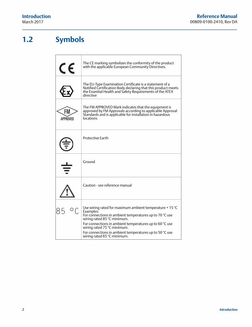
1.2 Symbols
The CE marking symbolizes the conformity of the product with the applicable European Community Directives.
The EU-Type Examination Certificate is a statement of a Notified Certification Body declaring that this product meets the Essential Health and Safety Requirements of the ATEX directive
The FM APPROVED Mark indicates that the equipment is approved by FM Approvals according to applicable Approval Standards and is applicable for installation in hazardous locations
Protective Earth
Ground
Caution - see reference manual
Use wiring rated for maximum ambient temperature + 15 °CExamples:For connections in ambient temperatures up to 70 °C use wiring rated 85 °C minimum.For connections in ambient temperatures up to 60 °C use wiring rated 75 °C minimum.For connections in ambient temperatures up to 50 °C use wiring rated 65 °C minimum.
2 Introduction
Reference Manual 00809-0100-2410, Rev DA
IntroductionMarch 2017
1.3 Manual overviewThis manual provides information on installation, configuration and maintenance of the Rosemount™ 2410 Tank Hub.
Section 2: Overview provides abrief description of the Rosemount Tank Gauging system and recommended installation procedure.
Section 3: Installation covers installation considerations as well as mechanical and electrical installation.
Section 4: Configuration describes how to configure the Rosemount 2410 Tank Hub by using the TankMaster WinSetup configuration program.
Section 5: Operation describes the integral display and how to specify display variables. It also includes start-up information, error messages, and LED functionality.
Section 6: Service and Troubleshooting covers tools, troubleshooting, and various service instructions.
Appendix A: Specifications and Reference Data contains specifications, dimensional drawings, and ordering table.
Appendix B: Product Certifications contains safety approval information and approval drawings.
Appendix C: Advanced Configuration describes various advanced configuration optons.
3Introduction
Reference Manual00809-0100-2410, Rev DA
IntroductionMarch 2017
1.4 Technical documentationThe Rosemount Tank Gauging System includes the following documentation:
Reference manuals Rosemount Tank Gauging System Configuration Manual (00809-0300-5100)
Rosemount 2460 Reference Manual (00809-0100-2460)
Rosemount 2410 Reference Manual (00809-0100-2410)
Rosemount 5900S Reference Manual (00809-0100-5900)
Rosemount 5900C Reference Manual (00809-0100-5901)
Rosemount 2240S Reference Manual (00809-0100-2240)
Rosemount 2230 Reference Manual (00809-0100-2230)
Rosemount 5300 Series Reference Manual (00809-0100-4530)
Rosemount 5400 Series Reference Manual (00809-0100-4026)
Rosemount Tank Gauging Wireless System Reference Manual (00809-0100-5200)
Rosemount TankMaster WinOpi Reference Manual (303028EN)
Product data sheets Rosemount Tank Gauging System Data Sheet (00813-0100-5100)
Rosemount 2460 System Hub Product Data Sheet (00813-0100-2460)
Rosemount 2410 Product Data Sheet (00813-0100-2410)
Rosemount 5900S Product Data Sheet (00813-0100-5900)
Rosemount 5900C Product Data Sheet (00813-0100-5901)
Rosemount 2240S Product Data Sheet (00813-0100-2240)
Rosemount 2230 Product Data Sheet (00813-0100-2230)
Rosemount 5300 Product Data Sheet (00813-0100-4530)
Rosemount 5400 Product Data Sheet (00813-0100-4026)
Drawings Rosemount Tank Gauging Installation Drawings
4 Introduction
Reference Manual 00809-0100-2410, Rev DA
IntroductionMarch 2017
1.5 Service supportFor service support contact the nearest Emerson Automation Solutions/Rosemount Tank Gauging represen-tative. Contact information can be found on the web site site emerson.com/rosemount tank gauging.
1.6 Product recycling/disposalRecycling of equipment and packaging should be taken into consideration and disposed of in accordance with local and national legislation/regulations.
1.7 Packing materialRosemount Tank Radar AB is fully certified according to ISO 14001 environmental standards. By recycling the corrugated paperboard, or wooden boxes, used for shipping our products you can contribute to take care of the environment.
1.7.1 Reuse and recyclingExperience has shown that wooden boxes can be used several times for various purposes. After careful disassembly the wooden parts may be reused. Metal waste may be converted.
1.7.2 Energy recoveryProducts which have served their time may be divided into wood and metal components and the wood can be used as fuel in sufficient ovens.
Due to its low moisture content (approximately 7%) this fuel has a higher calorific value than ordinary wood fuel (moisture content approximately 20%).
When burning interior plywood the nitrogen in the adhesives may increase emissions of nitrogen oxides to the air 3-4 times more than when burning bark and splinter.
NoteLandfill is not a recycling option and should be avoided.
5Introduction

6
Reference Manual00809-0100-2410, Rev DA
IntroductionMarch 2017
Introduction
Reference Manual 00809-0100-2410, Rev DA
OverviewMarch 2017
Section 2 Overview
Introduction . . . . . . . . . . . . . . . . . . . . . . . . . . . . . . . . . . . . . . . . . . . . . . . . . . . . . . . . . . . . . . . . . . . . . page 7Components . . . . . . . . . . . . . . . . . . . . . . . . . . . . . . . . . . . . . . . . . . . . . . . . . . . . . . . . . . . . . . . . . . . . . page 11System overview . . . . . . . . . . . . . . . . . . . . . . . . . . . . . . . . . . . . . . . . . . . . . . . . . . . . . . . . . . . . . . . . . page 12Installation procedure . . . . . . . . . . . . . . . . . . . . . . . . . . . . . . . . . . . . . . . . . . . . . . . . . . . . . . . . . . . . . page 19
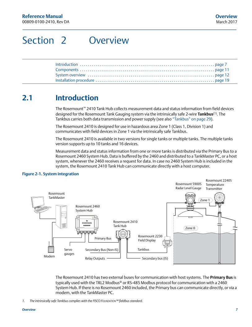
2.1 IntroductionThe Rosemount™ 2410 Tank Hub collects measurement data and status information from field devices designed for the Rosemount Tank Gauging system via the intrinsically safe 2-wire Tankbus(1). The Tankbus carries both data transmission and power supply (see also “Tankbus” on page 29).
The Rosemount 2410 is designed for use in hazardous area Zone 1 (Class 1, Division 1) and communicates with field devices in Zone 1 via the intrinsically safe Tankbus.
The Rosemount 2410 is available in two versions for single tanks or multiple tanks. The multiple tanks version supports up to 10 tanks and 16 devices.
Measurement data and status information from one or more tanks is distributed via the Primary Bus to a Rosemount 2460 System Hub. Data is buffered by the 2460 and distributed to a TankMaster PC, or a host system, whenever the 2460 receives a request for data. In case no 2460 System Hub is included in the system, the Rosemount 2410 Tank Hub can communicate directly with a host computer.
Figure 2-1. System integration
The Rosemount 2410 has two external buses for communication with host systems. The Primary Bus is typically used with the TRL2 Modbus® or RS-485 Modbus protocol for communication with a 2460 System Hub. If there is no Rosemount 2460 included, the Primary bus can communicate directly, or via a modem, with the TankMaster PC.
1. The intrinsically safe Tankbus complies with the FISCO FOUNDATION™ fieldbus standard.
Rosemount TankMaster
Rosemount 2410 Tank Hub
Modem
Rosemount 2460 System Hub
Relay Outputs
Secondary Bus (Non-IS)
Primary Bus
Tankbus
Rosemount 2240S Temperature Transmitter
Rosemount 2230 Field Display
Zone 1
Zone 0
Rosemount 5900S Radar Level Gauge
Secondary bus (IS)
Servo gauges
7Overview
Reference Manual00809-0100-2410, Rev DA
OverviewMarch 2017
The Secondary Bus supports various protocols such as TRL2 Modbus, Enraf®, and Varec which allows you to connect to other systems as well.
The Rosemount 2410 is equipped with two solid state relays that allows controlling external devices such as valves and pumps.
An integral display (optional) presents measurement data and device status such as warnings and error messages. At start-up, communication settings and optional hardware configuration is presented as well as whether it is a Single tank or Multiple tank version of the Rosemount 2410 Tank Hub.
Using the input from a Rosemount 5900S Radar Level Gauge and one or two pressure sensors, the Rosemount 2410 can be configured for online presentation of Observed Density to a host computer. The tank hub also calculates Average Temperature and strapping table based Volume.
The Rosemount 2410 can be equipped with two relays which can be controlled by level, temperature, and water level. The output can be connected to an external system for alarm indication or process control. The relays are user configurable for normally open or closed operation.
The Rosemount 2410 can be configured with up to ten “virtual” relay functions. This allows you to specify several different source variables to trigger a relay.
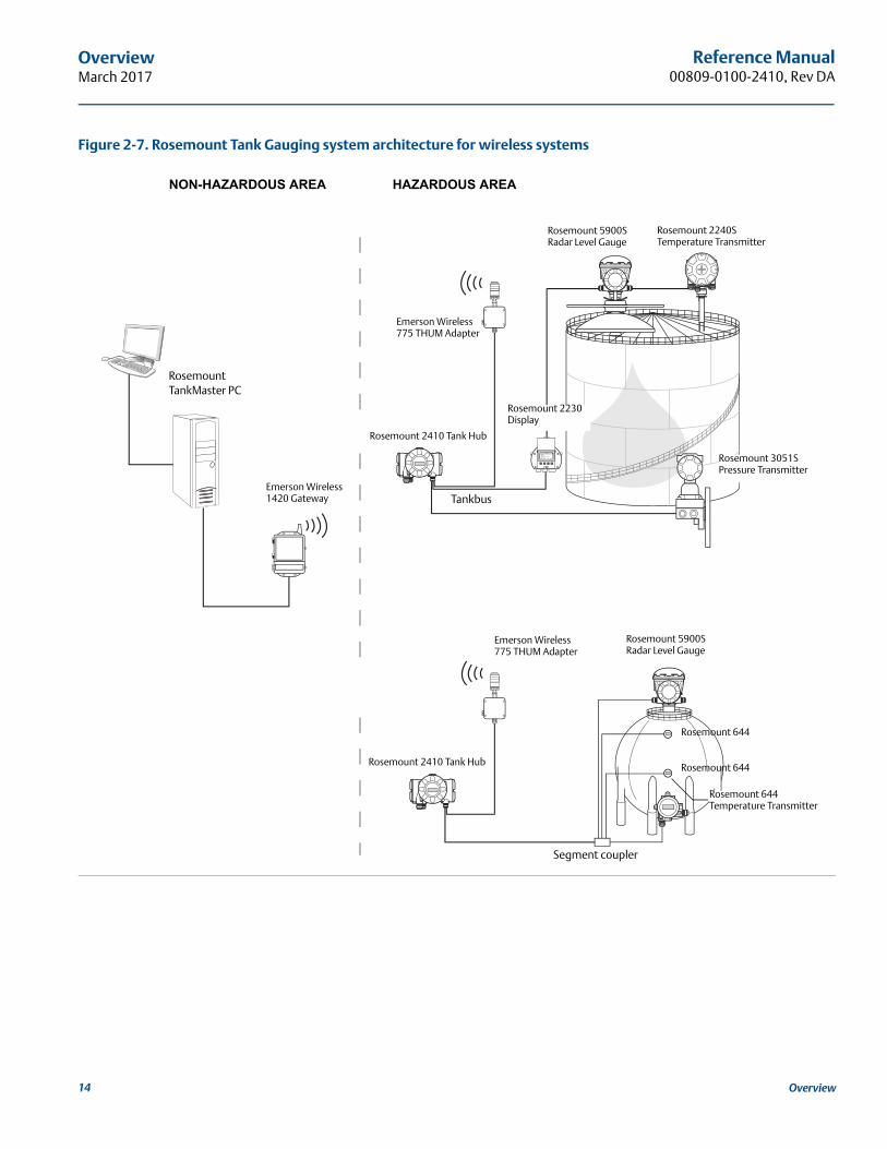
The Rosemount 2410 supports the Emerson’s Wireless solution, which is based on WirelessHART® the emerging industry standard for wireless field networks. By connecting to an Emerson Wireless 775 THUM™ Adapter, the Rosemount 2410 can be integrated in a wireless network to provide measurement data at greatly reduced field wiring costs. The tank hub supports communication with Emerson Wireless Gateways 1410 and 1420.
8 Overview
Reference Manual 00809-0100-2410, Rev DA
OverviewMarch 2017
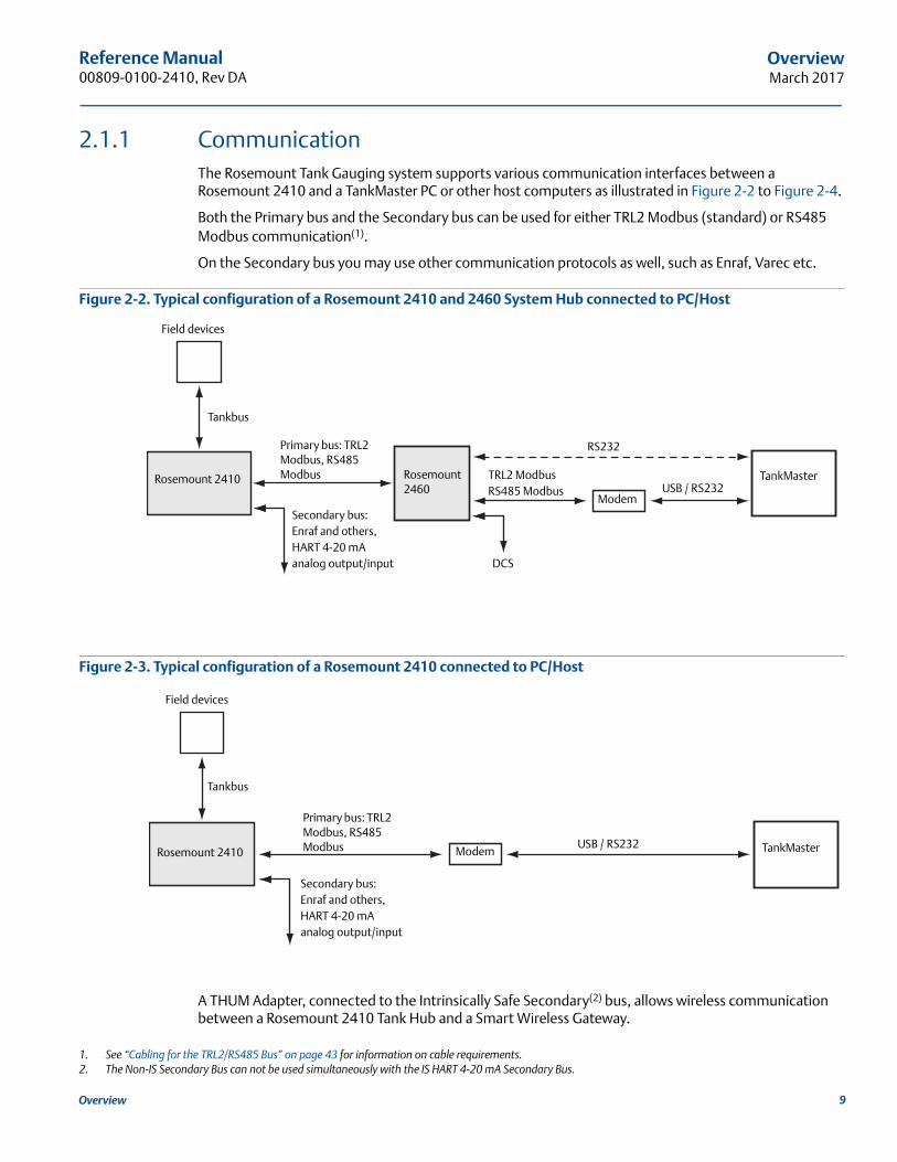
2.1.1 CommunicationThe Rosemount Tank Gauging system supports various communication interfaces between a Rosemount 2410 and a TankMaster PC or other host computers as illustrated in Figure 2-2 to Figure 2-4.
Both the Primary bus and the Secondary bus can be used for either TRL2 Modbus (standard) or RS485 Modbus communication(1).
On the Secondary bus you may use other communication protocols as well, such as Enraf, Varec etc.
Figure 2-2. Typical configuration of a Rosemount 2410 and 2460 System Hub connected to PC/Host
Figure 2-3. Typical configuration of a Rosemount 2410 connected to PC/Host
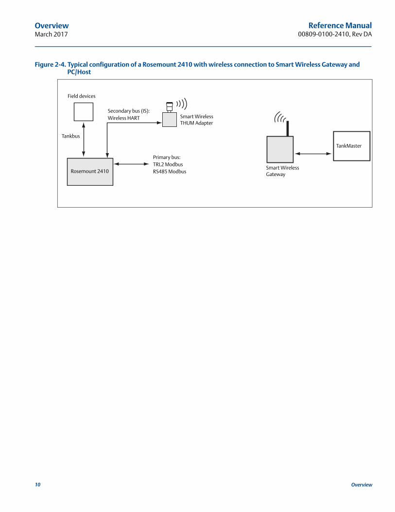
A THUM Adapter, connected to the Intrinsically Safe Secondary(2) bus, allows wireless communication between a Rosemount 2410 Tank Hub and a Smart Wireless Gateway.
1. See “Cabling for the TRL2/RS485 Bus” on page 43 for information on cable requirements.2. The Non-IS Secondary Bus can not be used simultaneously with the IS HART 4-20 mA Secondary Bus.
Modem
TankMasterRosemount 2460
RS232
USB / RS232
Primary bus: TRL2 Modbus, RS485 Modbus
Field devices
TRL2 ModbusRS485 Modbus
Rosemount 2410
Tankbus
DCS
Secondary bus:Enraf and others,HART 4-20 mA analog output/input
ModemUSB / RS232
Tankbus
Field devices
Rosemount 2410
Primary bus: TRL2 Modbus, RS485 Modbus TankMaster
Secondary bus:Enraf and others,HART 4-20 mA analog output/input
9Overview
Reference Manual00809-0100-2410, Rev DA
OverviewMarch 2017
Figure 2-4. Typical configuration of a Rosemount 2410 with wireless connection to Smart Wireless Gateway and PC/Host
Tankbus
Field devices
Rosemount 2410
Primary bus: TRL2 Modbus RS485 Modbus
TankMaster
Smart Wireless THUM Adapter
Smart Wireless Gateway
Secondary bus (IS):Wireless HART
10 Overview
Reference Manual 00809-0100-2410, Rev DA
OverviewMarch 2017
2.2 Components
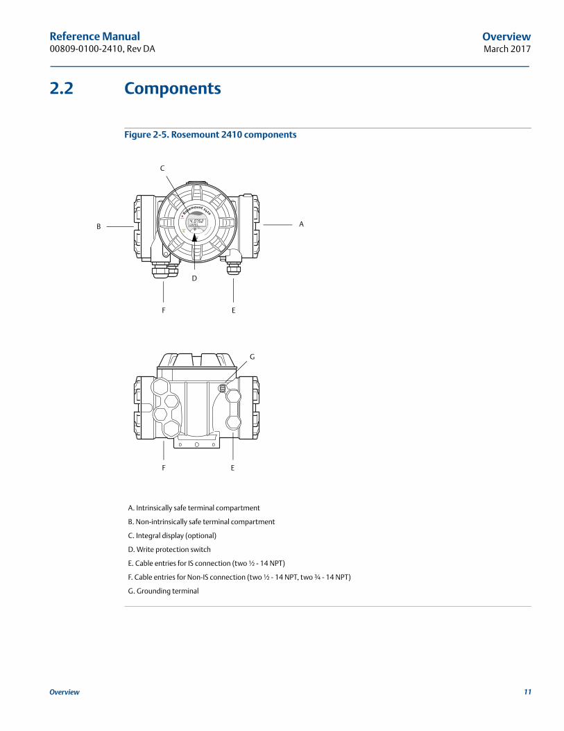
Figure 2-5. Rosemount 2410 components
A. Intrinsically safe terminal compartment
B. Non-intrinsically safe terminal compartment
C. Integral display (optional)
D. Write protection switch
E. Cable entries for IS connection (two ½ - 14 NPT)
F. Cable entries for Non-IS connection (two ½ - 14 NPT, two ¾ - 14 NPT)
G. Grounding terminal
B A
C
D
G
F E
EF
11Overview
Reference Manual00809-0100-2410, Rev DA
OverviewMarch 2017
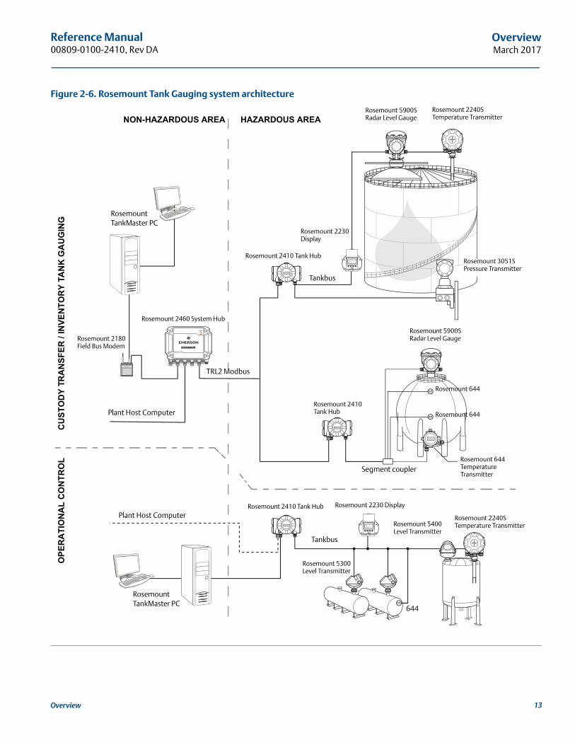
2.3 System overviewThe Rosemount Tank Gauging system is a state-of-the art inventory and custody transfer radar tank level gauging system. It is developed for a wide range of applications at refineries, tank farms and fuel depots, and fulfills the highest requirements on performance and safety.
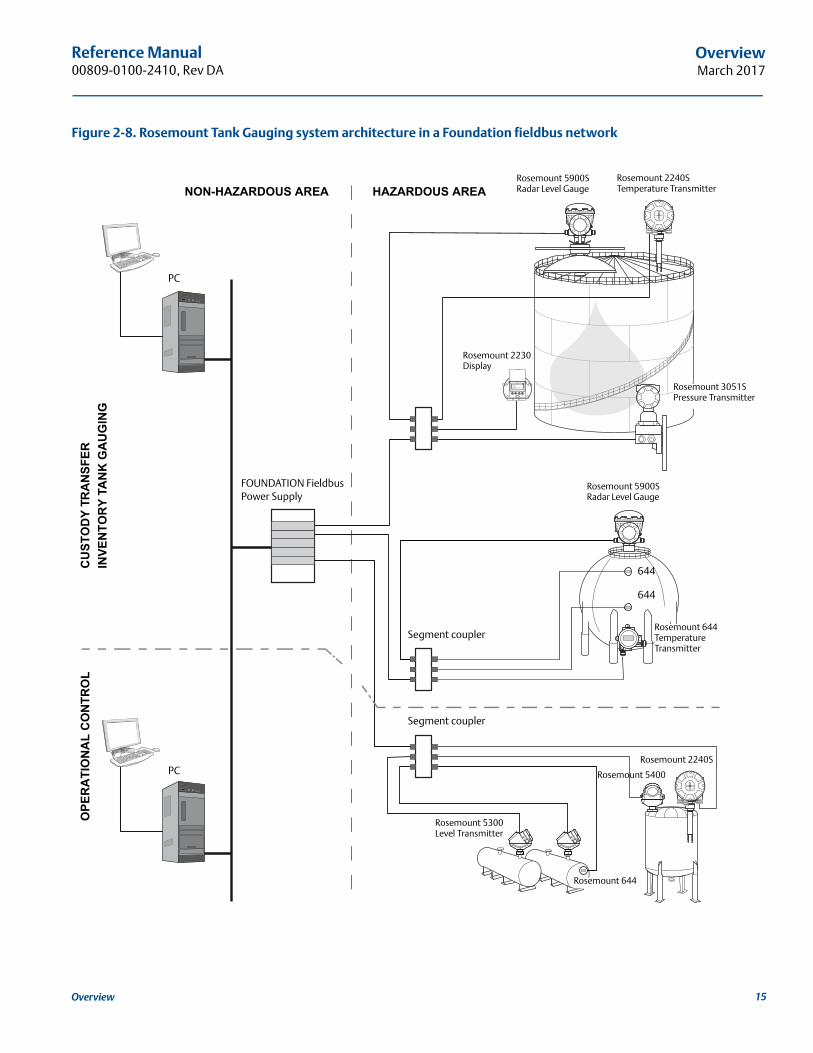
The field devices on the tank communicate over the intrinsically safe Tankbus. The Tankbus is based on a standardized fieldbus, the FISCO(1) FOUNDATION™ fieldbus, and allows integration of any device supporting that protocol. By utilizing a bus powered 2-wire intrinsically safe fieldbus the power consumption is minimized. The standardized fieldbus also enables integration of other vendors’ equipment on the tank.
The Rosemount Tank Gauging product portfolio includes a wide range of components to build small or large customized tank gauging systems. The system includes various devices, such as radar level gauges, temperature transmitters, and pressure transmitters for complete inventory control. Such systems are easily expanded thanks to the modular design.
The Rosemount Tank Gauging system is a versatile system that is compatible with and can emulate all major tank gauging systems. Moreover, the well-proven emulation capability enables step-by-step modernization of a tank farm, from level gauges to control room solutions.
It is possible to replace old mechanical or servo gauges with modern Rosemount Tank Gauging devices, without replacing the control system or field cabling. It is further possible to replace old HMI/SCADA-sys-tems and field communication devices without replacing the old gauges.
There is a distributed intelligence in the various system units which continuously collect and process measurement data and status information. When a request for information is received an immediate response is sent with updated information.
The flexible Rosemount Tank Gauging system supports several combinations to achieve redundancy, from control room to the different field devices. Redundant network configuration can be achieved at all levels by doubling each unit and using multiple control room work stations.
1. See documents IEC 61158-2 and IEC/TS 60079-27
12 Overview
Reference Manual 00809-0100-2410, Rev DA
OverviewMarch 2017
Figure 2-6. Rosemount Tank Gauging system architecture
Rosemount 2230 Display
Rosemount 2240S Temperature Transmitter
Rosemount 5900S Radar Level Gauge
Tankbus
Rosemount 5300 Level Transmitter
Rosemount 5400 Level Transmitter
Rosemount 3051S Pressure Transmitter
TRL2 Modbus
Rosemount 2180 Field Bus Modem
Rosemount 2460 System Hub
Rosemount TankMaster PC
Plant Host Computer
Rosemount 644
644
Plant Host Computer
NON-HAZARDOUS AREA HAZARDOUS AREA
Rosemount 2410 Tank Hub
Rosemount 5900S Radar Level Gauge
Tankbus
Segment coupler
CU
ST
OD
Y T
RA
NS
FE
R /
INV
EN
TO
RY
TA
NK
GA
UG
ING
OP
ER
AT
ION
AL
CO
NT
RO
L Rosemount 644 Temperature Transmitter
Rosemount 2410 Tank Hub
Rosemount 2410 Tank Hub
Rosemount 2240S Temperature Transmitter
Rosemount TankMaster PC
Rosemount 644
Rosemount 2230 Display
13Overview
Reference Manual00809-0100-2410, Rev DA
OverviewMarch 2017
Figure 2-7. Rosemount Tank Gauging system architecture for wireless systems
Emerson Wireless 1420 Gateway
NON-HAZARDOUS AREA HAZARDOUS AREA
Tankbus
Segment coupler
Emerson Wireless 775 THUM Adapter
Rosemount 5900S Radar Level Gauge
Rosemount 2240S Temperature Transmitter
Rosemount 2230 Display
Rosemount 3051S Pressure Transmitter
Rosemount 2410 Tank Hub
Rosemount 2410 Tank Hub
Rosemount 5900S Radar Level Gauge
Rosemount TankMaster PC
Rosemount 644 Temperature Transmitter
Rosemount 644
Rosemount 644
Emerson Wireless 775 THUM Adapter
14 Overview
Reference Manual 00809-0100-2410, Rev DA
OverviewMarch 2017
Figure 2-8. Rosemount Tank Gauging system architecture in a Foundation fieldbus network
PC
644
644
NON-HAZARDOUS AREA HAZARDOUS AREA
Segment coupler
Segment coupler
FOUNDATION Fieldbus Power Supply
CU
ST
OD
Y T
RA
NS
FE
R
INV
EN
TO
RY
TA
NK
GA
UG
ING
OP
ER
AT
ION
AL
CO
NT
RO
L
Rosemount 644
PC
Rosemount 5900S Radar Level Gauge
Rosemount 2240S Temperature Transmitter
Rosemount 3051S Pressure Transmitter
Rosemount 5900S Radar Level Gauge
Rosemount 644 Temperature Transmitter
Rosemount 5300 Level Transmitter
Rosemount 5400
Rosemount 2240S
Rosemount 2230 Display
15Overview
Reference Manual00809-0100-2410, Rev DA
OverviewMarch 2017
TankMaster HMI softwareRosemount TankMaster is a powerful Windows-based Human Machine Interface (HMI) for complete tank inventory management. It provides configuration, service, set-up, inventory, and custody transfer functions for Rosemount Tank Gauging systems and other supported instruments.
TankMaster is designed to be used in the Microsoft® Windows environment providing easy access to measurement data from your Local Area Network (LAN).
The TankMaster WinOpi program lets the operator monitor measured tank data. It includes alarm handling, batch reports, automatic report handling, historical data sampling as well as inventory calculations such as Volume, Observed Density and other parameters. A plant host computer can be connected for further processing of data.
The TankMaster WinSetup program is a graphical user interface for installation, configuration and service of devices in the Rosemount Tank Gauging system.
Rosemount 2460 System HubThe Rosemount 2460 System Hub is a data concentrator that continuously polls and stores data from field devices such as radar level gauges and temperature transmitters in a buffer memory. Whenever a request for data is received, the system hub can immediately send data from the updated buffer memory for a group of tanks.
Rosemount 2410 Tank HubThe Rosemount 2410 Tank Hub acts as a power supply to the connected field devices in the hazardous area using the intrinsically safe Tankbus.
The tank hub collects measurement data and status information from field devices on a tank. It has two external buses for communication with various host systems.
There are two versions of the Rosemount 2410 Tank Hub; one for single tank operation and one for multiple tanks operation. The multiple tanks version of the Rosemount 2410 supports up to 10 tanks and 16 devices. With the Rosemount 5300 and Rosemount 5400 level transmitters the Rosemount 2410 supports up to 5 tanks.
The Rosemount 2410 is equipped with two relays which support configuration of up to 10 “virtual” relay functions allowing you to specify several source signals for each relay.
The Rosemount 2410 supports Intrinsically Safe (IS) and Non-Intrinsically Safe (Non-IS) analog 4-20 mA inputs/outputs. By connecting an Emerson™ Wireless 775 THUM™ Adapter to the IS HART 4-20 mA output, the tank hub is capable of wireless communication with an Emerson Wireless Gateway in a WirelessHART® network.
16 Overview
Reference Manual 00809-0100-2410, Rev DA
OverviewMarch 2017
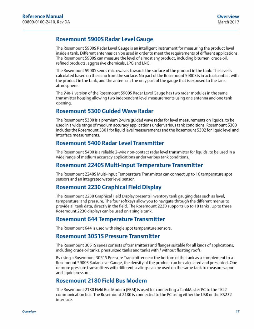
Rosemount 5900S Radar Level GaugeThe Rosemount 5900S Radar Level Gauge is an intelligent instrument for measuring the product level inside a tank. Different antennas can be used in order to meet the requirements of different applications. The Rosemount 5900S can measure the level of almost any product, including bitumen, crude oil, refined products, aggressive chemicals, LPG and LNG.
The Rosemount 5900S sends microwaves towards the surface of the product in the tank. The level is calculated based on the echo from the surface. No part of the Rosemount 5900S is in actual contact with the product in the tank, and the antenna is the only part of the gauge that is exposed to the tank atmosphere.
The 2-in-1 version of the Rosemount 5900S Radar Level Gauge has two radar modules in the same transmitter housing allowing two independent level measurements using one antenna and one tank opening.
Rosemount 5300 Guided Wave RadarThe Rosemount 5300 is a premium 2-wire guided wave radar for level measurements on liquids, to be used in a wide range of medium accuracy applications under various tank conditions. Rosemount 5300 includes the Rosemount 5301 for liquid level measurements and the Rosemount 5302 for liquid level and interface measurements.
Rosemount 5400 Radar Level TransmitterThe Rosemount 5400 is a reliable 2-wire non-contact radar level transmitter for liquids, to be used in a wide range of medium accuracy applications under various tank conditions.
Rosemount 2240S Multi-Input Temperature TransmitterThe Rosemount 2240S Multi-input Temperature Transmitter can connect up to 16 temperature spot sensors and an integrated water level sensor.
Rosemount 2230 Graphical Field DisplayThe Rosemount 2230 Graphical Field Display presents inventory tank gauging data such as level, temperature, and pressure. The four softkeys allow you to navigate through the different menus to provide all tank data, directly in the field. The Rosemount 2230 supports up to 10 tanks. Up to three Rosemount 2230 displays can be used on a single tank.
Rosemount 644 Temperature TransmitterThe Rosemount 644 is used with single spot temperature sensors.
Rosemount 3051S Pressure TransmitterThe Rosemount 3051S series consists of transmitters and flanges suitable for all kinds of applications, including crude oil tanks, pressurized tanks and tanks with / without floating roofs.
By using a Rosemount 3051S Pressure Transmitter near the bottom of the tank as a complement to a Rosemount 5900S Radar Level Gauge, the density of the product can be calculated and presented. One or more pressure transmitters with different scalings can be used on the same tank to measure vapor and liquid pressure.
Rosemount 2180 Field Bus ModemThe Rosemount 2180 Field Bus Modem (FBM) is used for connecting a TankMaster PC to the TRL2 communication bus. The Rosemount 2180 is connected to the PC using either the USB or the RS232 interface.
17Overview

Reference Manual00809-0100-2410, Rev DA
OverviewMarch 2017
Emerson Wireless Gateways and Emerson Wireless 775 THUM AdapterAn Emerson Wireless THUM Adapter allows wireless communication between a Rosemount 2410 Tank Hub and an Emerson Wireless Gateway. The gateway is the network manager that provides an interface between field devices and the TankMaster inventory software or host / DCS systems.
See the Rosemount Tank Gauging System Data Sheet (Document No. 00813-0100-5100) for more information on the various devices and options.
18 Overview
Reference Manual 00809-0100-2410, Rev DA
OverviewMarch 2017
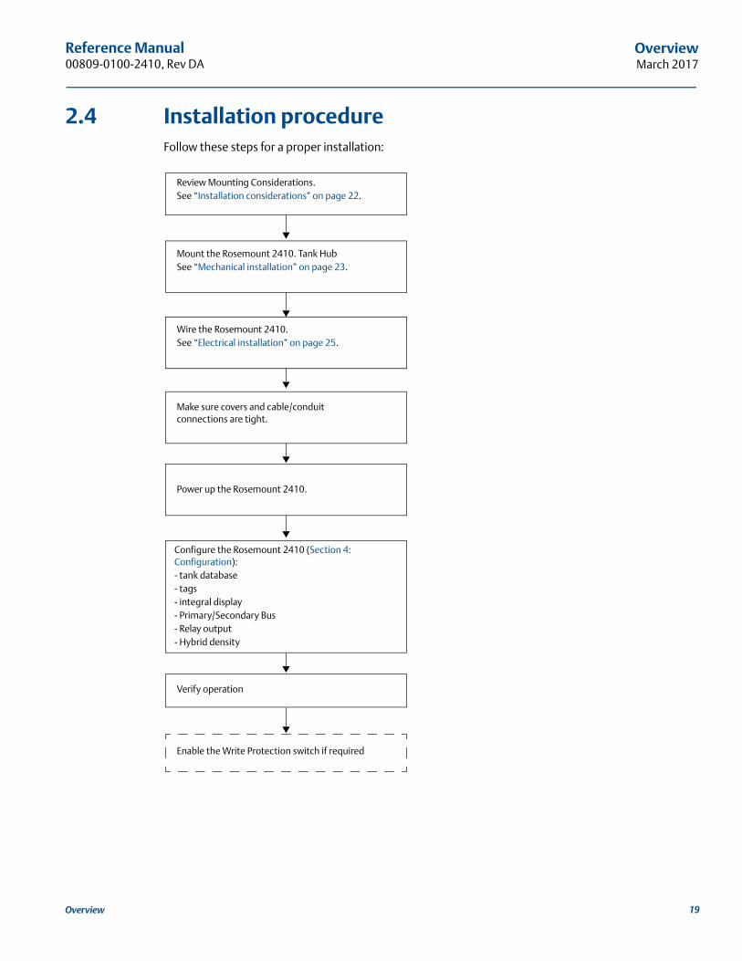
2.4 Installation procedureFollow these steps for a proper installation:
Review Mounting Considerations.See “Installation considerations” on page 22.
Mount the Rosemount 2410. Tank HubSee “Mechanical installation” on page 23.
Wire the Rosemount 2410.See “Electrical installation” on page 25.
Make sure covers and cable/conduit connections are tight.
Power up the Rosemount 2410.
Configure the Rosemount 2410 (Section 4: Configuration):- tank database- tags- integral display- Primary/Secondary Bus- Relay output- Hybrid density
Verify operation
Enable the Write Protection switch if required
19Overview

Reference Manual00809-0100-2410, Rev DA
OverviewMarch 2017
20 Overview

Reference Manual 00809-0100-2410, Rev DA
InstallationMarch 2017
Section 3 Installation
Safety messages . . . . . . . . . . . . . . . . . . . . . . . . . . . . . . . . . . . . . . . . . . . . . . . . . . . . . . . . . . . . . . . . . . page 21Installation considerations . . . . . . . . . . . . . . . . . . . . . . . . . . . . . . . . . . . . . . . . . . . . . . . . . . . . . . . . . page 22Mechanical installation . . . . . . . . . . . . . . . . . . . . . . . . . . . . . . . . . . . . . . . . . . . . . . . . . . . . . . . . . . . . page 23Electrical installation . . . . . . . . . . . . . . . . . . . . . . . . . . . . . . . . . . . . . . . . . . . . . . . . . . . . . . . . . . . . . . page 25
3.1 Safety messagesProcedures and instructions in this section may require special precautions to ensure the safety of the personnel performing the operations. Information that raises potential safety issues is indicated by a
warning symbol ( ). Please refer to the following safety messages before performing an operation preceded by this symbol.
Failure to follow safe installation and servicing guidelines could result in death or serious injury:
Make sure only qualified personnel perform the installation.
Use the equipment only as specified in this manual. Failure to do so may impair the protection provided by the equipment.
Do not perform any service other than those contained in this manual unless you are qualified.
Explosions could result in death or serious injury:
Verify that the operating environment of the device is consistent with the appropriate hazardous locations certifications.
Before connecting a communicator in an explosive atmosphere, make sure the instruments in the loop are installed in accordance with intrinsically safe or non-incendive field wiring practices.
Do not remove the gauge cover in explosive atmospheres when the circuit is alive.
To prevent ignition of flammable or combustible atmospheres, disconnect power before servicing.
High voltage that may be present on leads could cause electrical shock:
Avoid contact with leads and terminals.
Make sure the main power to the Rosemount 2410 Tank Hub is off and the lines to any other external power source are disconnected or not powered while wiring the gauge.
21Installation
Reference Manual00809-0100-2410, Rev DA
InstallationMarch 2017
3.2 Installation considerationsThe Rosemount™ 2410 Tank Hub may be installed on various locations at the plant. Mounting at the tank foot may be convenient when you would like to have easy access to measuring data, diagnostics and other information on the optional integral display.
The Rosemount 2410 Tank Hub can also be mounted on the tank roof if this is the preferred location. In case the tank hub is exposed to long periods of sunshine, a sunshade should be used to prevent it from being heated to temperatures above the maximum operating temperature.
Ensure that environmental conditions are within specified limits as listed in Appendix A: Specifications and Reference Data.
Ensure that the Rosemount 2410 is installed such that it is not exposed to higher pressure and temperature than specified in Appendix A: Specifications and Reference Data.
The multi-tank version of the Rosemount 2410 Tank Hub is able to serve several tanks. In that case it may be placed at a suitable location further away from the tanks.
The Rosemount 2410 is designed with two Tankbus terminals and several cable entries which allows alternative cable routings to suit various requirements.
Do not install the Rosemount 2410 in non-intended applications, for example environments where it may be exposed to extremely intense magnetic fields or extreme weather conditions.
It’s a good idea to plan the installation in order ensure that all components in the system are properly specified. The planning stage should include the following tasks:
make a plan of the site and specify suitable locations for the devices
consider power budget
specify cabling and connections (for example whether devices will be “daisy-chained” or not)
specify cable glands that will be needed for the various devices
specify location of terminators on the Tankbus
make a note of identification codes such as Unit ID/Device ID of each device
assign Modbus™ addresses for level gauges and other tank devices to be used in the tank database of the Rosemount 2410 and the tank database of the Rosemount 2460 System Hub (see the Rosemount Tank Gauging System Configuration manual, document no. 00809-0300-5100 for more information)
See “Electrical installation” on page 25 for more information on cables and glands.
ImportantCheck the Rosemount 2410 Tank Hub for any signs of damage prior to installation. Ensure that the glass on the integral display is undamaged, and O-rings and gaskets are in good condition.
22 Installation
Reference Manual 00809-0100-2410, Rev DA
InstallationMarch 2017
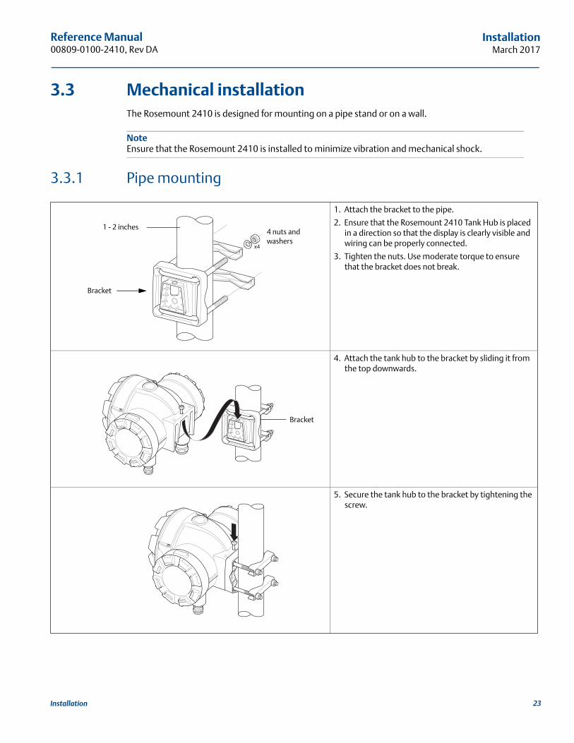
3.3 Mechanical installationThe Rosemount 2410 is designed for mounting on a pipe stand or on a wall.
NoteEnsure that the Rosemount 2410 is installed to minimize vibration and mechanical shock.
3.3.1 Pipe mounting
1. Attach the bracket to the pipe.
2. Ensure that the Rosemount 2410 Tank Hub is placed in a direction so that the display is clearly visible and wiring can be properly connected.
3. Tighten the nuts. Use moderate torque to ensure that the bracket does not break.
4. Attach the tank hub to the bracket by sliding it from the top downwards.
5. Secure the tank hub to the bracket by tightening the screw.
Bracket
4 nuts and washers
1 - 2 inches
Bracket
23Installation
Reference Manual00809-0100-2410, Rev DA
InstallationMarch 2017
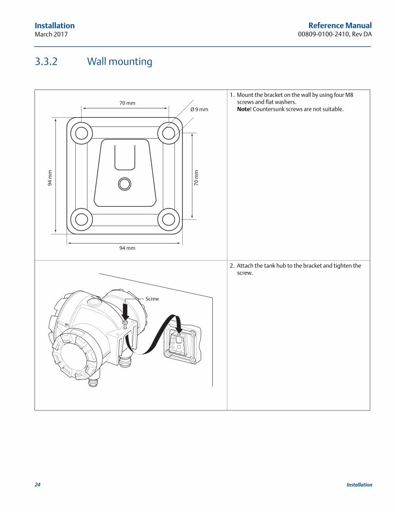
3.3.2 Wall mounting
1. Mount the bracket on the wall by using four M8 screws and flat washers.Note! Countersunk screws are not suitable.
2. Attach the tank hub to the bracket and tighten the screw.
70 mm
70 m
m
94 m
m
94 mm
Ø 9 mm
Screw
24 Installation

Reference Manual 00809-0100-2410, Rev DA
InstallationMarch 2017
3.4 Electrical installation
3.4.1 Cable entriesThe Rosemount 2410 electronics housing has four ½ - 14 NPT and two ¾ - 14 NPT entries. The connections must be made in accordance with local or plant electrical codes.
Make sure that unused ports are properly sealed to prevent moisture or other contamination from entering the terminal block compartment of the electronics housing.
NoteUse the enclosed metal plugs to seal unused ports. The plastic plugs mounted at delivery are not sufficient as seal!
NoteIt is recommended that a sealant of type PTFE is used to prevent water ingress and to enable future removal of the plug/gland.
NPT is a standard for tapered threads. Engage the gland with 5 to 6 threads. Note that there will be a number of threads left outside the housing as illustrated below.
Figure 3-1. Cable entry with NPT threaded gland
Glands must meet the following requirements for the Non-IS cable entries:
Ex de explosion protection
IP class 66 and 67
material: metal (recommended)
3.4.2 Power supplyThe Rosemount 2410 Tank Hub accepts supply voltage 48 - 240 Vac (50/60 Hz) and 24 - 48 Vdc. The Rosemount 2410 provides intrinsically safe power to all devices connected to the Tankbus (see “Tankbus” on page 29).
A. The NPT threaded gland leaves a number of threads outside the housing
A
25Installation
Reference Manual00809-0100-2410, Rev DA
InstallationMarch 2017
3.4.3 Cable selection for power supplyCables must be suitable for the supply voltage and approved for use in hazardous areas, where applicable. For instance, in the U.S., explosion-proof conduits must be used in the vicinity of the vessel.
Suitable conduits with sealing device or flame proof cable glands must be used depending on local requirements.
Appropriate cross sectional area of wires must be used in order to prevent a too high voltage drop to the connected device. Use 0.75 mm2 to 2.5 mm2 (18 AWG to 13 AWG) in order to minimize the voltage drop.
3.4.4 GroundingThe housing should always be grounded in accordance with national and local electrical codes. Failure to do so may impair the protection provided by the equipment. The most effective grounding method is direct connection to earth ground with minimal impedance. There are grounding screw connections
inside the terminal compartments which are identified by ground symbols: / . There is also a grounding screw on the housing.
NoteGrounding the device via threaded conduit connection may not provide sufficient ground.
Grounding - TankbusSignal wiring of the fieldbus segment (Tankbus) can not be grounded. Grounding one of the signal wires may shut down the entire fieldbus segment.
Shield Wire Ground
Tankbus
To protect the fieldbus segment (Tankbus) from noise, grounding techniques for shield wire usually require a single grounding point for shield wire to avoid creating a ground loop. The ground point is typically at the power supply.
The Rosemount Tank Gauging devices are designed for “daisy-chain” connection of shield wiring in order to enable a continuous shield throughout the Tankbus network.
Primary/Secondary Bus
Cable shield for the Primary and Secondary Bus should normally be grounded at host or System Hub end only.
26 Installation
Reference Manual 00809-0100-2410, Rev DA
InstallationMarch 2017
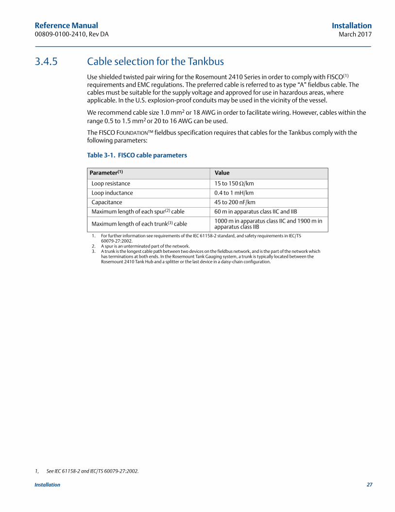
3.4.5 Cable selection for the TankbusUse shielded twisted pair wiring for the Rosemount 2410 Series in order to comply with FISCO(1) requirements and EMC regulations. The preferred cable is referred to as type “A” fieldbus cable. The cables must be suitable for the supply voltage and approved for use in hazardous areas, where applicable. In the U.S. explosion-proof conduits may be used in the vicinity of the vessel.
We recommend cable size 1.0 mm2 or 18 AWG in order to facilitate wiring. However, cables within the range 0.5 to 1.5 mm2 or 20 to 16 AWG can be used.
The FISCO FOUNDATION™ fieldbus specification requires that cables for the Tankbus comply with the following parameters:
Table 3-1. FISCO cable parameters
1, See IEC 61158-2 and IEC/TS 60079-27:2002.
Parameter(1)
1. For further information see requirements of the IEC 61158-2 standard, and safety requirements in IEC/TS 60079-27:2002.
Value
Loop resistance 15 to 150 /km
Loop inductance 0.4 to 1 mH/km
Capacitance 45 to 200 nF/km
Maximum length of each spur(2) cable
2. A spur is an unterminated part of the network.
60 m in apparatus class IIC and IIB
Maximum length of each trunk(3) cable
3. A trunk is the longest cable path between two devices on the fieldbus network, and is the part of the network which has terminations at both ends. In the Rosemount Tank Gauging system, a trunk is typically located between the Rosemount 2410 Tank Hub and a splitter or the last device in a daisy-chain configuration.
1000 m in apparatus class IIC and 1900 m in apparatus class IIB
27Installation
Reference Manual00809-0100-2410, Rev DA
InstallationMarch 2017
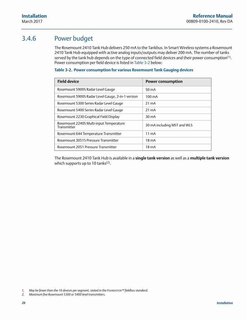
3.4.6 Power budgetThe Rosemount 2410 Tank Hub delivers 250 mA to the Tankbus. In Smart Wireless systems a Rosemount 2410 Tank Hub equipped with active analog inputs/outputs may deliver 200 mA. The number of tanks served by the tank hub depends on the type of connected field devices and their power consumption(1). Power consumption per field device is listed in Table 3-2 below:
Table 3-2. Power consumption for various Rosemount Tank Gauging devices
The Rosemount 2410 Tank Hub is available in a single tank version as well as a multiple tank version which supports up to 10 tanks(2).
1, May be fewer than the 16 devices per segment, stated in the FOUNDATION™ fieldbus standard.
Field device Power consumption
Rosemount 5900S Radar Level Gauge 50 mA
Rosemount 5900S Radar Level Gauge, 2-in-1 version 100 mA
Rosemount 5300 Series Radar Level Gauge 21 mA
Rosemount 5400 Series Radar Level Gauge 21 mA
Rosemount 2230 Graphical Field Display 30 mA
Rosemount 2240S Multi-input Temperature Transmitter 30 mA including MST and WLS
Rosemount 644 Temperature Transmitter 11 mA
Rosemount 3051S Pressure Transmitter 18 mA
Rosemount 2051 Pressure Transmitter 18 mA
2, Maximum five Rosemount 5300 or 5400 level transmitters.
28 Installation
Reference Manual 00809-0100-2410, Rev DA
InstallationMarch 2017
3.4.7 TankbusThe Rosemount Tank Gaugingsystem is easy to install and wire. Devices can be “daisy-chained” thus reducing the number of external junction boxes.
In a Rosemount Tank Gaugingsystem the field devices communicate with a Rosemount 2410 Tank Hub via the intrinsically safe Tankbus. The Tankbus complies with the FISCO(1) FOUNDATION fieldbus standard. The Rosemount 2410 acts as a power supply to the field devices on the Tankbus.
The tank hub is designed for use in hazardous area Zone 1 (Class 1, Division 1) and communicates with field devices via the intrinsically safe Tankbus.
TerminationA terminator is needed at each end of the trunk in a FOUNDATION fieldbus network. A trunk is defined as the longest cable path between two devices on the fieldbus network. In the Rosemount Tank Gaugingsystem, a trunk is typically located between the Rosemount 2410 Tank Hub and a splitter or the last device in a daisy-chain configuration. Generally, one terminator is placed in the fieldbus power supply, and the other one in the last device in the fieldbus network as illustrated in Figure 3-7 on page 36.
NoteEnsure that there are two terminators on the fieldbus.
In a Rosemount Tank Gaugingsystem the Rosemount 2410 Tank Hub acts as a power supply. The tank hub is normally the first device in the fieldbus segment, and the built-in termination is enabled at factory.
Other devices such as the Rosemount 5900S Radar Level Gauge, the Rosemount 2230 Graphical Field Display, and the Rosemount 2240S Multi-input Temperature Transmitter also have built-in terminators which can easily be enabled by inserting a jumper in the terminal block when necessary.
When adding new devices at the end of an existing FOUNDATION™ fieldbus network, the termination is moved to the farthest field device in order to fulfill the requirement on locating the terminator at the end of the trunk. However, in case a field device is added to the network with a short cable, this rule may be slightly bent by leaving the terminator in its original position.
Fieldbus segment designWhen designing a FISCO fieldbus segment you will have to make sure that cabling complies with FISCO requirements as described in “Cable selection for the Tankbus” on page 27.
You will also have to ensure that the total operating current of the connected field devices is within the output capability of the Rosemount 2410 Tank Hub. The tank hub is able to deliver 250(2) mA. Consequently, the total number of field devices has to be considered so that the total current consumption is less than 250 mA, see “Power budget” on page 28.
Since the field devices on the Tankbus must have at least a 9 V input voltage at their terminals, you will have to take into account the voltage drop in the fieldbus cables. In many cases distances are relatively short between the Rosemount 2410 and field devices on the tank and you may use existing cables as long as the FISCO requirements are fulfilled (see “Cable selection for the Tankbus” on page 27).
1, FISCO=Fieldbus Intrinsically Safe Concept2, In Smart Wireless Systems the Rosemount 2410 can deliver 200 mA on the Tankbus
29Installation
Reference Manual00809-0100-2410, Rev DA
InstallationMarch 2017
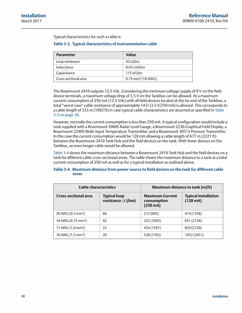
Typical characteristics for such a cable is:
Table 3-3. Typical characteristics of instrumentation cable
The Rosemount 2410 outputs 12.5 Vdc. Considering the minimum voltage supply of 9 V on the field device terminals, a maximum voltage drop of 3.5 V on the Tankbus can be allowed. At a maximum current consumption of 250 mA (12.5 Vdc) with all field devices located at the far end of the Tankbus, a total “worst case” cable resistance of approximately 14 Ù (3.5 V/250 mA) is allowed. This corresponds to a cable length of 333 m (1092 ft) in case typical cable characteristics are assumed as specified in Table 3-3 on page 30.
However, normally the current consumption is less than 250 mA. A typical configuration would include a tank supplied with a Rosemount 5900S Radar Level Gauge, a Rosemount 2230 Graphical Field Display, a Rosemount 2240S Multi-input Temperature Transmitter, and a Rosemount 3051S Pressure Transmitter. In this case the current consumption would be 128 mA allowing a cable length of 677 m (2221 ft) between the Rosemount 2410 Tank Hub and the field devices on the tank. With fewer devices on the Tankbus, an even longer cable would be allowed.
Table 3-4 shows the maximum distance between a Rosemount 2410 Tank Hub and the field devices on a tank for different cable cross-sectional areas. The table shows the maximum distance to a tank at a total current consumption of 250 mA as well as for a typical installation as outlined above.
Table 3-4. Maximum distance from power source to field devices on the tank for different cable areas
Parameter Value
Loop resistance 42 /km
Inductance 0.65 mH/km
Capacitance 115 nF/km
Cross-sectional area 0.75 mm2 (18 AWG)
Cable characteristics Maximum distance to tank (m/ft)
Cross-sectional area Typical loop resistance /km)
Maximum Current consumption (250 mA)
Typical installation (128 mA)
20 AWG (0.5 mm2) 66 212 (695) 414 (1358)
18 AWG (0.75 mm2) 42 333 (1092) 651 (2136)
17 AWG (1.0 mm2) 33 424 (1391) 829 (2720)
16 AWG (1.5 mm2) 26 538 (1765) 1052 (3451)
30 Installation
Reference Manual 00809-0100-2410, Rev DA
InstallationMarch 2017
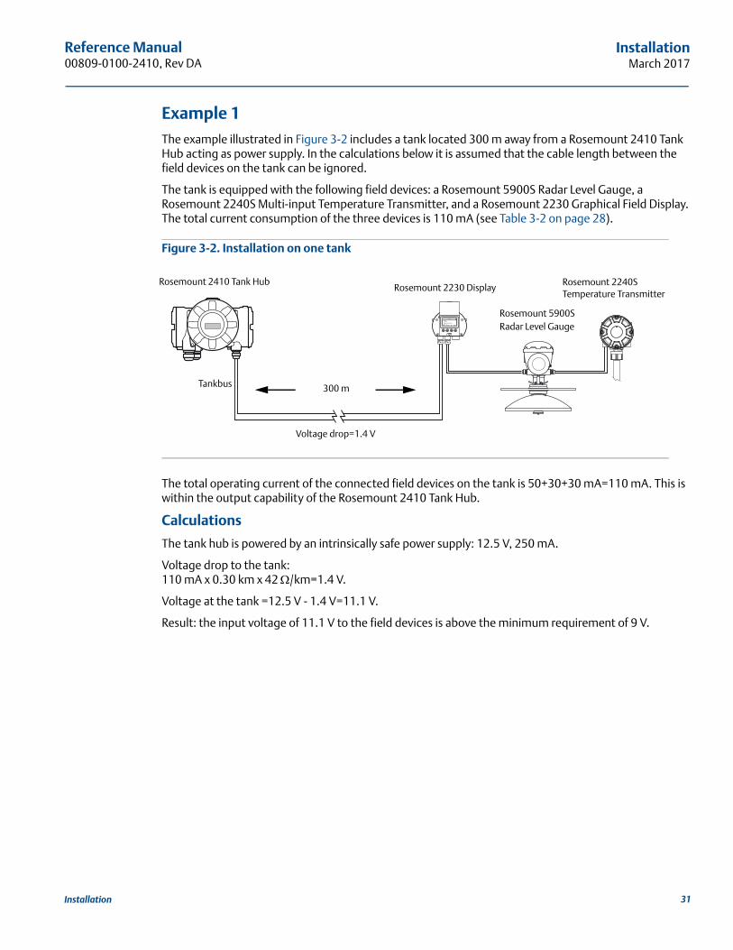
Example 1The example illustrated in Figure 3-2 includes a tank located 300 m away from a Rosemount 2410 Tank Hub acting as power supply. In the calculations below it is assumed that the cable length between the field devices on the tank can be ignored.
The tank is equipped with the following field devices: a Rosemount 5900S Radar Level Gauge, a Rosemount 2240S Multi-input Temperature Transmitter, and a Rosemount 2230 Graphical Field Display. The total current consumption of the three devices is 110 mA (see Table 3-2 on page 28).
Figure 3-2. Installation on one tank
The total operating current of the connected field devices on the tank is 50+30+30 mA=110 mA. This is within the output capability of the Rosemount 2410 Tank Hub.
Calculations
The tank hub is powered by an intrinsically safe power supply: 12.5 V, 250 mA.
Voltage drop to the tank:110 mA x 0.30 km x 42 /km=1.4 V.
Voltage at the tank =12.5 V - 1.4 V=11.1 V.
Result: the input voltage of 11.1 V to the field devices is above the minimum requirement of 9 V.
Rosemount 2410 Tank Hub
Rosemount 5900S Radar Level Gauge
Rosemount 2230 Display
300 m
Voltage drop=1.4 V
Tankbus
Rosemount 2240S Temperature Transmitter
31Installation
Reference Manual00809-0100-2410, Rev DA
InstallationMarch 2017
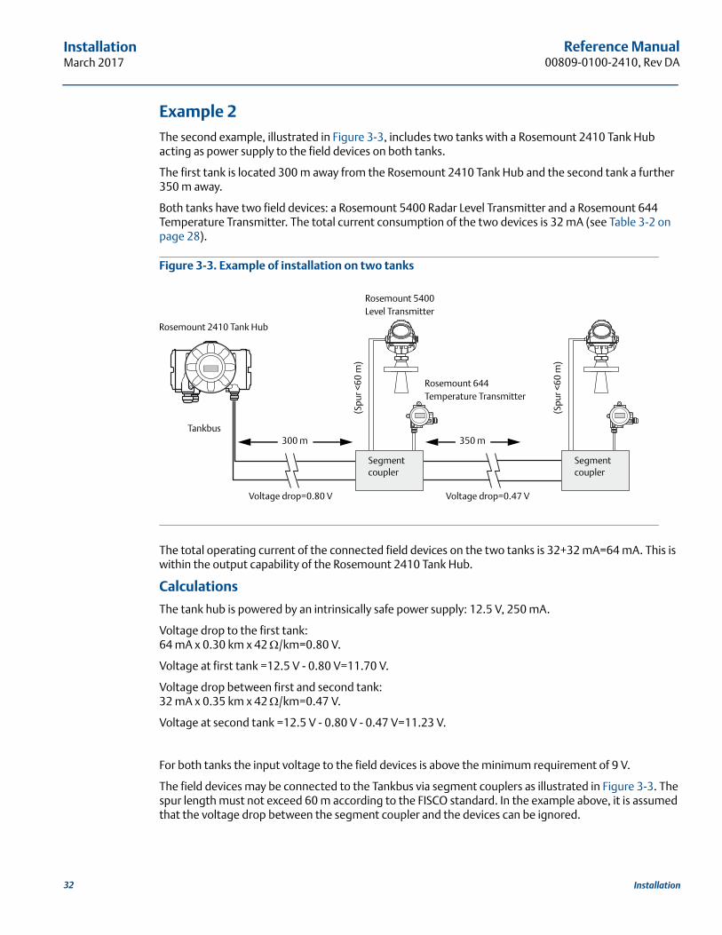
Example 2The second example, illustrated in Figure 3-3, includes two tanks with a Rosemount 2410 Tank Hub acting as power supply to the field devices on both tanks.
The first tank is located 300 m away from the Rosemount 2410 Tank Hub and the second tank a further 350 m away.
Both tanks have two field devices: a Rosemount 5400 Radar Level Transmitter and a Rosemount 644 Temperature Transmitter. The total current consumption of the two devices is 32 mA (see Table 3-2 on page 28).
Figure 3-3. Example of installation on two tanks
The total operating current of the connected field devices on the two tanks is 32+32 mA=64 mA. This is within the output capability of the Rosemount 2410 Tank Hub.
Calculations
The tank hub is powered by an intrinsically safe power supply: 12.5 V, 250 mA.
Voltage drop to the first tank:64 mA x 0.30 km x 42 /km=0.80 V.
Voltage at first tank =12.5 V - 0.80 V=11.70 V.
Voltage drop between first and second tank:32 mA x 0.35 km x 42 /km=0.47 V.
Voltage at second tank =12.5 V - 0.80 V - 0.47 V=11.23 V.
For both tanks the input voltage to the field devices is above the minimum requirement of 9 V.
The field devices may be connected to the Tankbus via segment couplers as illustrated in Figure 3-3. The spur length must not exceed 60 m according to the FISCO standard. In the example above, it is assumed that the voltage drop between the segment coupler and the devices can be ignored.
Rosemount 5400 Level Transmitter
Rosemount 644 Temperature Transmitter
300 m 350 m
Voltage drop=0.80 V Voltage drop=0.47 V
Segment coupler
Tankbus
(Spu
r <60
m)
(Spu
r <60
m)
Segment coupler
Rosemount 2410 Tank Hub
32 Installation
Reference Manual 00809-0100-2410, Rev DA
InstallationMarch 2017
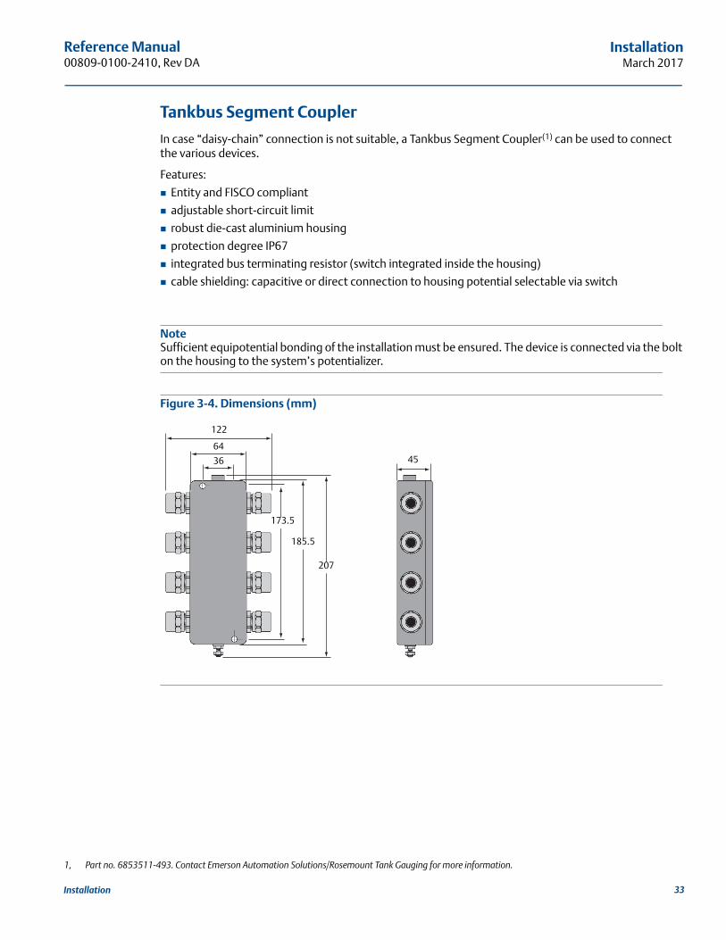
Tankbus Segment Coupler
In case “daisy-chain” connection is not suitable, a Tankbus Segment Coupler(1) can be used to connect the various devices.
Features:
Entity and FISCO compliant
adjustable short-circuit limit
robust die-cast aluminium housing
protection degree IP67
integrated bus terminating resistor (switch integrated inside the housing)
cable shielding: capacitive or direct connection to housing potential selectable via switch
NoteSufficient equipotential bonding of the installation must be ensured. The device is connected via the bolt on the housing to the system’s potentializer.
Figure 3-4. Dimensions (mm)
1, Part no. 6853511-493. Contact Emerson Automation Solutions/Rosemount Tank Gauging for more information.
122
64
36 45
173.5
185.5
207
33Installation
Reference Manual00809-0100-2410, Rev DA
InstallationMarch 2017
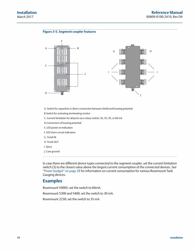
Figure 3-5. Segment coupler features
In case there are different device types connected to the segment coupler, set the current limitation switch (3) to the closest value above the largest current consumption of the connected devices. See “Power budget” on page 28 for information on current consumption for various Rosemount Tank Gauging devices.
ExamplesRosemount 5900S; set the switch to 60mA.
Rosemount 5300 and 5400; set the switch to 30 mA.
Rosemount 2230; set the switch to 35 mA.
A. Switch for capacitive or direct connection between shield and housing potential
B.Switch for activating terminating resistor
C. Current limitation for all ports via a rotary switch; 30, 35, 45, or 60 mA
D.Connection of housing potential
E. LED power on indication
F. LED short-circuit indication
G. Trunk IN
H. Trunk OUT
I. Spurs
J. Case ground
A B
C
D
F
E
G H
I I
J
34 Installation
Reference Manual 00809-0100-2410, Rev DA
InstallationMarch 2017
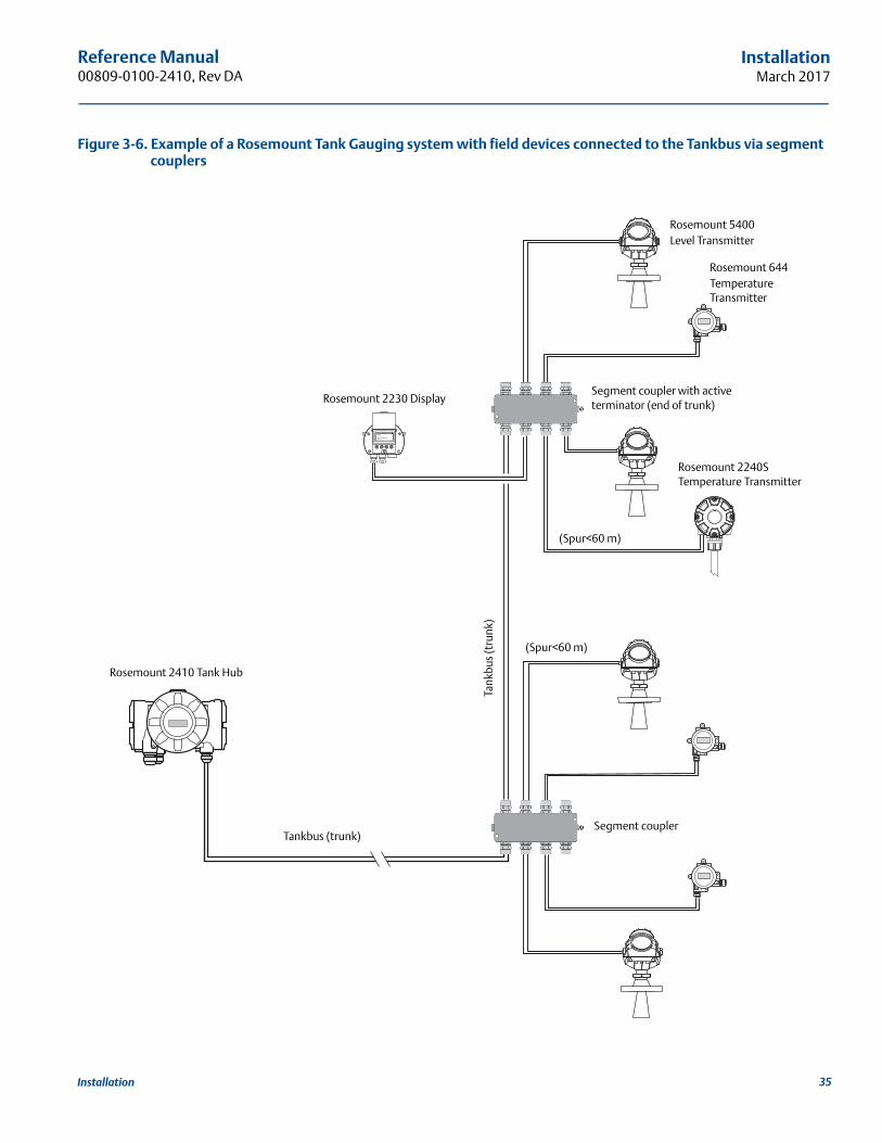
Figure 3-6. Example of a Rosemount Tank Gauging system with field devices connected to the Tankbus via segment couplers
Tankbus (trunk)
(Spur<60 m)
(Spur<60 m)
Rosemount 2410 Tank Hub
Rosemount 5400Level Transmitter
Rosemount 644Temperature Transmitter
Segment coupler
Rosemount 2240S Temperature Transmitter
Rosemount 2230 Display
Tank
bus
(tru
nk)
Segment coupler with active terminator (end of trunk)
35Installation
Reference Manual00809-0100-2410, Rev DA
InstallationMarch 2017
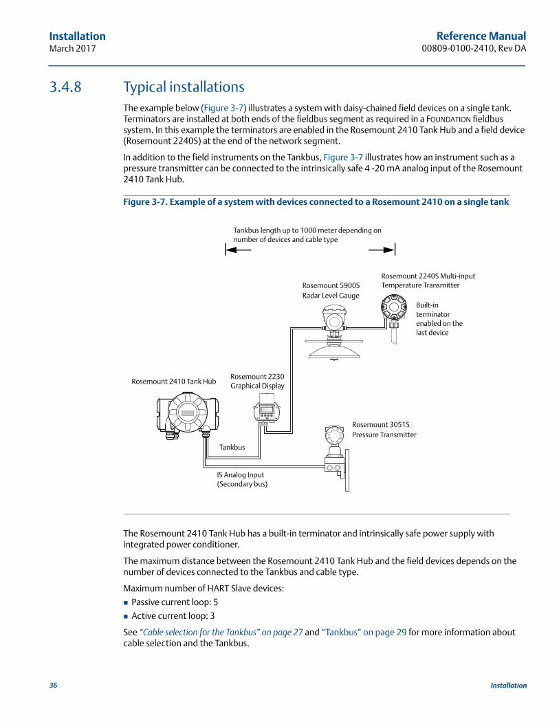
3.4.8 Typical installationsThe example below (Figure 3-7) illustrates a system with daisy-chained field devices on a single tank. Terminators are installed at both ends of the fieldbus segment as required in a FOUNDATION fieldbus system. In this example the terminators are enabled in the Rosemount 2410 Tank Hub and a field device (Rosemount 2240S) at the end of the network segment.
In addition to the field instruments on the Tankbus, Figure 3-7 illustrates how an instrument such as a pressure transmitter can be connected to the intrinsically safe 4 -20 mA analog input of the Rosemount 2410 Tank Hub.
Figure 3-7. Example of a system with devices connected to a Rosemount 2410 on a single tank
The Rosemount 2410 Tank Hub has a built-in terminator and intrinsically safe power supply with integrated power conditioner.
The maximum distance between the Rosemount 2410 Tank Hub and the field devices depends on the number of devices connected to the Tankbus and cable type.
Maximum number of HART Slave devices:
Passive current loop: 5
Active current loop: 3
See “Cable selection for the Tankbus” on page 27 and “Tankbus” on page 29 for more information about cable selection and the Tankbus.
Rosemount 5900S Radar Level Gauge
Rosemount 2240S Multi-input Temperature Transmitter
Built-in terminator enabled on the last device
Rosemount 2230 Graphical Display
Rosemount 2410 Tank Hub
Tankbus length up to 1000 meter depending on number of devices and cable type
Tankbus
IS Analog Input (Secondary bus)
Rosemount 3051S Pressure Transmitter
36 Installation
Reference Manual 00809-0100-2410, Rev DA
InstallationMarch 2017
Non I.S. current loop alternative options:
1. Passive current loop. Input voltage range: 10.5 - 35 V
2. Active current loop. Output voltage range: 12.8 - 24 V @ 21.75 - 0 mA.
I.S. current loop alternative options:
1. Passive current loop. Input voltage range: 10.5 - 30 V
2. Active current loop. Output voltage range: 6.2 - 23 V @ 21.75 - 0 mA.
Note polarity for connection of polarity sensitive buses and I/O (for example RS485 and analog I/O).
See “Intrinsically safe terminal block” on page 53 for information on the Intrinsically Safe terminal block.
See Appendix A: Specifications and Reference Data for more information on electrical characteristics for analog input and output.
37Installation
Reference Manual00809-0100-2410, Rev DA
InstallationMarch 2017
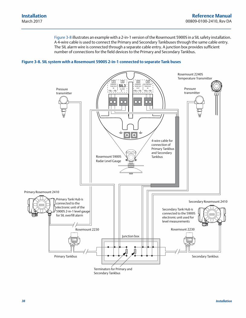
Figure 3-8 illustrates an example with a 2-in-1 version of the Rosemount 5900S in a SIL safety installation. A 4-wire cable is used to connect the Primary and Secondary Tankbuses through the same cable entry. The SIL alarm wire is connected through a separate cable entry. A junction box provides sufficient number of connections for the field devices to the Primary and Secondary Tankbus.
Figure 3-8. SIL system with a Rosemount 5900S 2-in-1 connected to separate Tank buses
Rosemount 5900S Radar Level Gauge
Rosemount 2240S Temperature Transmitter
Junction box
Rosemount 2230
Pressure transmitter
Pressure transmitter
Terminators for Primary and Secondary Tankbus
Primary Rosemount 2410
4-wire cable for connection of Primary Tankbus and Secondary Tankbus
Primary Tank Hub is connected to the electronic unit of the 5900S 2-in-1 level gauge for SIL overfill alarm
Secondary Rosemount 2410
Primary Tankbus Secondary Tankbus
Rosemount 2230
Secondary Tank Hub is connected to the 5900S electronic unit used for level measurements
38 Installation
Reference Manual 00809-0100-2410, Rev DA
InstallationMarch 2017
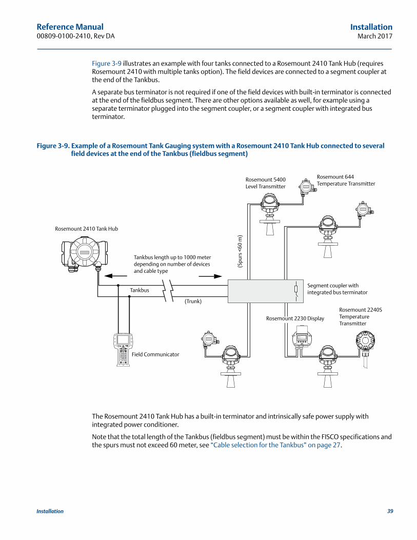
Figure 3-9 illustrates an example with four tanks connected to a Rosemount 2410 Tank Hub (requires Rosemount 2410 with multiple tanks option). The field devices are connected to a segment coupler at the end of the Tankbus.
A separate bus terminator is not required if one of the field devices with built-in terminator is connected at the end of the fieldbus segment. There are other options available as well, for example using a separate terminator plugged into the segment coupler, or a segment coupler with integrated bus terminator.
Figure 3-9. Example of a Rosemount Tank Gauging system with a Rosemount 2410 Tank Hub connected to several field devices at the end of the Tankbus (fieldbus segment)
The Rosemount 2410 Tank Hub has a built-in terminator and intrinsically safe power supply with integrated power conditioner.
Note that the total length of the Tankbus (fieldbus segment) must be within the FISCO specifications and the spurs must not exceed 60 meter, see “Cable selection for the Tankbus” on page 27.
Rosemount 2410 Tank Hub
(Trunk)
Rosemount 2240S Temperature Transmitter
Field Communicator
Tankbus
Rosemount 5400 Level Transmitter
(Spu
rs <
60 m
)
Rosemount 644 Temperature Transmitter
Rosemount 2230 Display
Tankbus length up to 1000 meter depending on number of devices and cable type
Segment coupler with integrated bus terminator
39Installation
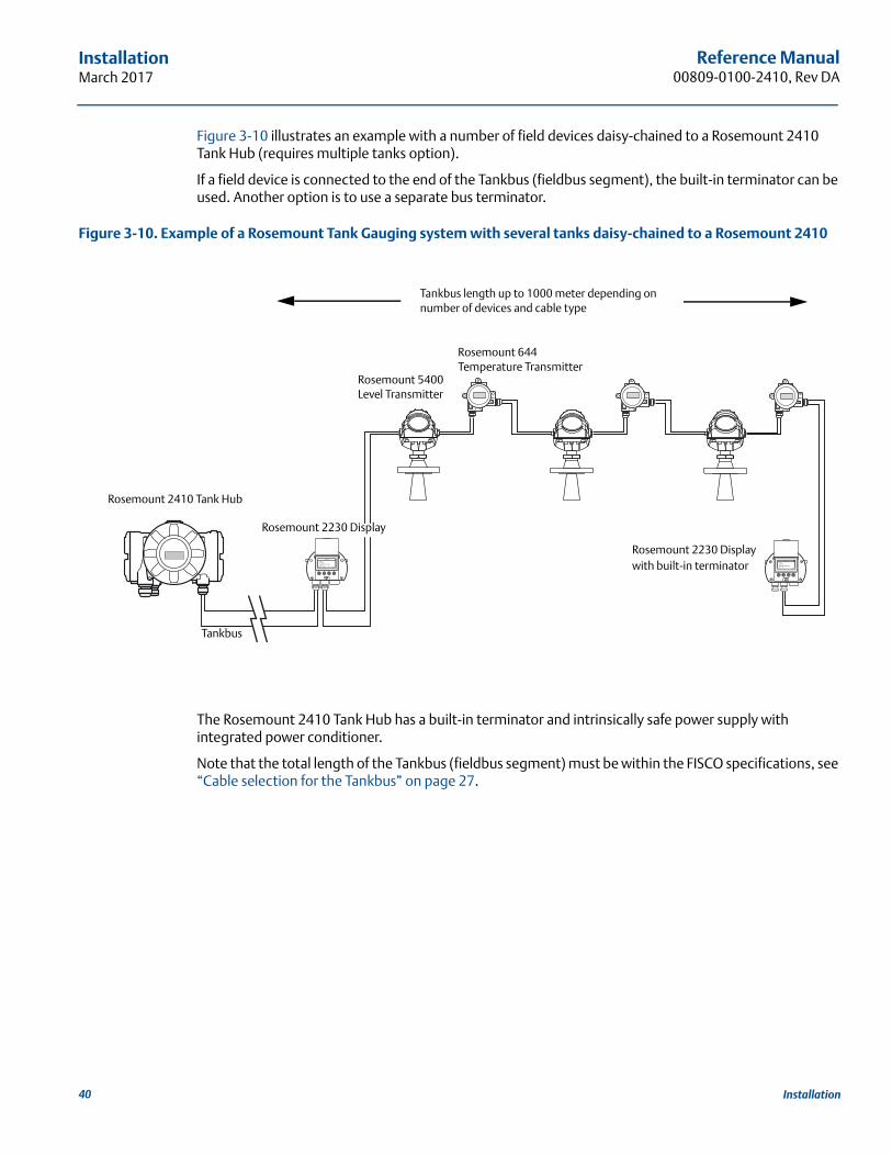
Reference Manual00809-0100-2410, Rev DA
InstallationMarch 2017
Figure 3-10 illustrates an example with a number of field devices daisy-chained to a Rosemount 2410 Tank Hub (requires multiple tanks option).
If a field device is connected to the end of the Tankbus (fieldbus segment), the built-in terminator can be used. Another option is to use a separate bus terminator.
Figure 3-10. Example of a Rosemount Tank Gauging system with several tanks daisy-chained to a Rosemount 2410
The Rosemount 2410 Tank Hub has a built-in terminator and intrinsically safe power supply with integrated power conditioner.
Note that the total length of the Tankbus (fieldbus segment) must be within the FISCO specifications, see “Cable selection for the Tankbus” on page 27.
Tankbus
Rosemount 2230 Display with built-in terminator
Tankbus length up to 1000 meter depending on number of devices and cable type
Rosemount 2410 Tank Hub
Rosemount 5400 Level Transmitter
Rosemount 644 Temperature Transmitter
Rosemount 2230 Display
40 Installation
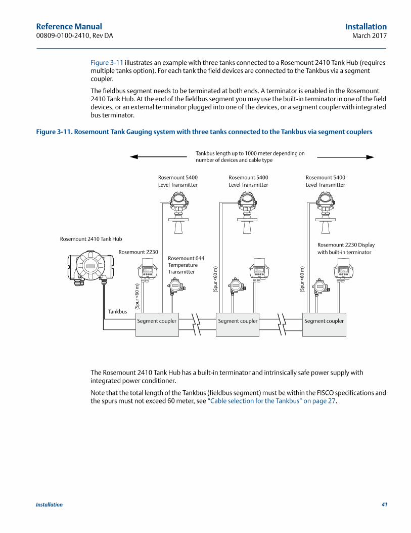
Reference Manual 00809-0100-2410, Rev DA
InstallationMarch 2017
Figure 3-11 illustrates an example with three tanks connected to a Rosemount 2410 Tank Hub (requires multiple tanks option). For each tank the field devices are connected to the Tankbus via a segment coupler.
The fieldbus segment needs to be terminated at both ends. A terminator is enabled in the Rosemount 2410 Tank Hub. At the end of the fieldbus segment you may use the built-in terminator in one of the field devices, or an external terminator plugged into one of the devices, or a segment coupler with integrated bus terminator.
Figure 3-11. Rosemount Tank Gauging system with three tanks connected to the Tankbus via segment couplers
The Rosemount 2410 Tank Hub has a built-in terminator and intrinsically safe power supply with integrated power conditioner.
Note that the total length of the Tankbus (fieldbus segment) must be within the FISCO specifications and the spurs must not exceed 60 meter, see “Cable selection for the Tankbus” on page 27.
Tankbus
Rosemount 644 Temperature Transmitter
(Spu
r <60
m)
Rosemount 2410 Tank Hub
Segment coupler
Rosemount 2230 Display with built-in terminator
Tankbus length up to 1000 meter depending on number of devices and cable type
Segment coupler Segment coupler
Rosemount 5400 Level Transmitter
Rosemount 2230
(Spu
r <60
m)
(Spu
r <60
m)
Rosemount 5400 Level Transmitter
Rosemount 5400 Level Transmitter
41Installation
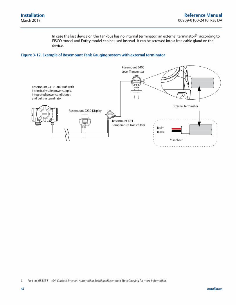
Reference Manual00809-0100-2410, Rev DA
InstallationMarch 2017
In case the last device on the Tankbus has no internal terminator, an external terminator(1) according to FISCO model and Entity model can be used instead. It can be screwed into a free cable gland on the device.
Figure 3-12. Example of Rosemount Tank Gauging system with external terminator
1, Part no. 6853511-494. Contact Emerson Automation Solutions/Rosemount Tank Gauging for more information.
Rosemount 644 Temperature Transmitter
External terminator
Rosemount 5400Level Transmitter
Rosemount 2410 Tank Hub with intrinsically safe power supply, integrated power conditioner, and built-in terminator
Rosemount 2230 Display
½ inch NPT
Red+Black-
42 Installation
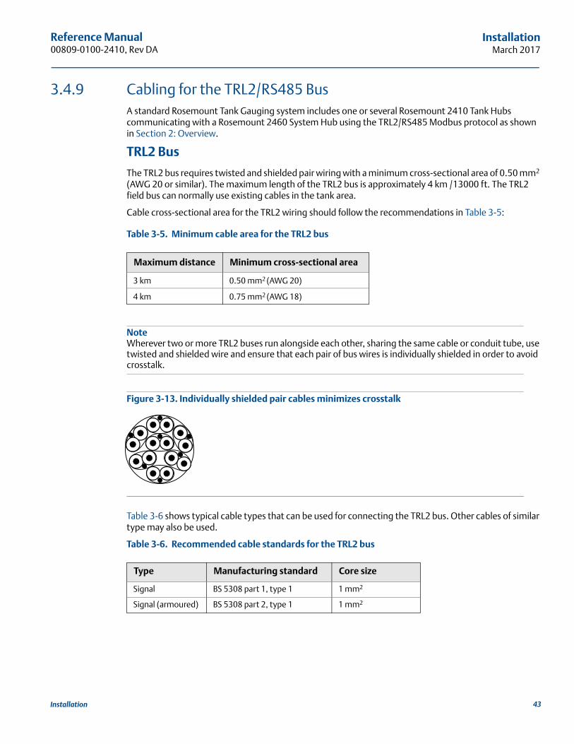
Reference Manual 00809-0100-2410, Rev DA
InstallationMarch 2017
3.4.9 Cabling for the TRL2/RS485 BusA standard Rosemount Tank Gauging system includes one or several Rosemount 2410 Tank Hubs communicating with a Rosemount 2460 System Hub using the TRL2/RS485 Modbus protocol as shown in Section 2: Overview.
TRL2 Bus
The TRL2 bus requires twisted and shielded pair wiring with a minimum cross-sectional area of 0.50 mm2 (AWG 20 or similar). The maximum length of the TRL2 bus is approximately 4 km /13000 ft. The TRL2 field bus can normally use existing cables in the tank area.
Cable cross-sectional area for the TRL2 wiring should follow the recommendations in Table 3-5:
Table 3-5. Minimum cable area for the TRL2 bus
NoteWherever two or more TRL2 buses run alongside each other, sharing the same cable or conduit tube, use twisted and shielded wire and ensure that each pair of bus wires is individually shielded in order to avoid crosstalk.
Figure 3-13. Individually shielded pair cables minimizes crosstalk
Table 3-6 shows typical cable types that can be used for connecting the TRL2 bus. Other cables of similar type may also be used.
Table 3-6. Recommended cable standards for the TRL2 bus
Maximum distance Minimum cross-sectional area
3 km 0.50 mm2 (AWG 20)
4 km 0.75 mm2 (AWG 18)
Type Manufacturing standard Core size
Signal BS 5308 part 1, type 1 1 mm2
Signal (armoured) BS 5308 part 2, type 1 1 mm2
43Installation

Reference Manual00809-0100-2410, Rev DA
InstallationMarch 2017
RS485 BusThe RS485 bus should meet the following requirements:
twisted and shielded pair wiring
characteristic impedance of 120 maximum cable length 1200 m / 4000 ft.
44 Installation
Reference Manual 00809-0100-2410, Rev DA
InstallationMarch 2017
3.4.10 Non-IS connectionThe non-IS explosion-proof/flameproof compartment has a terminal block for connecting power supply, communication buses to host systems, relay outputs, and HART® 4-20 mA analog input and output.
1. Ensure that the power supply is switched off.
2. Ensure that the cover jam screw (F) (see Figure 3-14 on page 46) is completely threaded into the housing. It is intended to disallow the removal of the transmitter cover in flameproof environments without the use of tooling. The cover jam screw is threaded into the housing at factory.
3. Remove the cover on the non-IS terminal compartment.
4. Run the wires through the cable gland/conduit. Install wiring with a drip loop in such a way that the lower part of the loop is under the cable/conduit entry.
5. Connect wires to the terminal block. See Table 3-8 on page 49 for information on the terminal block connections.
6. Use the enclosed metal plug to seal any unused port.
7. Tighten the conduits/cable glands.
8. Attach and tighten the cover. Ensure that it is fully engaged to meet explosion-proof requirements and to prevent water from entering the terminal compartment.
9. Loosen the cover jam screw until it contacts the cover. Turn the jam screw an additional 1/2 turn counterclockwise to secure the cover (Note: application of excessive torque may strip the threads).
10.Verify that the cover cannot be removed.
NoteEnsure that o-rings and seats are in good condition prior to mounting the cover in order to maintain the specified level of ingress protection. The same requirements apply for cable inlets and outlets (or plugs). Cables must be properly attached to the cable glands.
45Installation
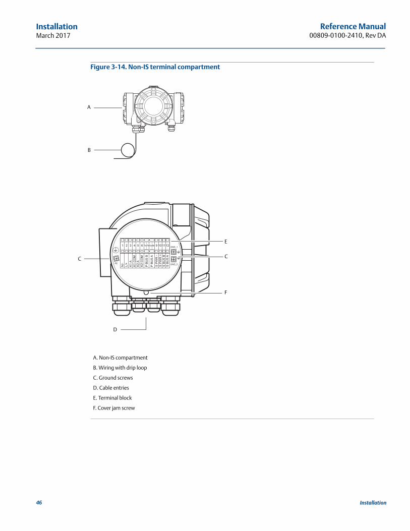
Reference Manual00809-0100-2410, Rev DA
InstallationMarch 2017
Figure 3-14. Non-IS terminal compartment
A. Non-IS compartment
B. Wiring with drip loop
C. Ground screws
D. Cable entries
E. Terminal block
F. Cover jam screw
A
F
D
C
B
C
E
46 Installation
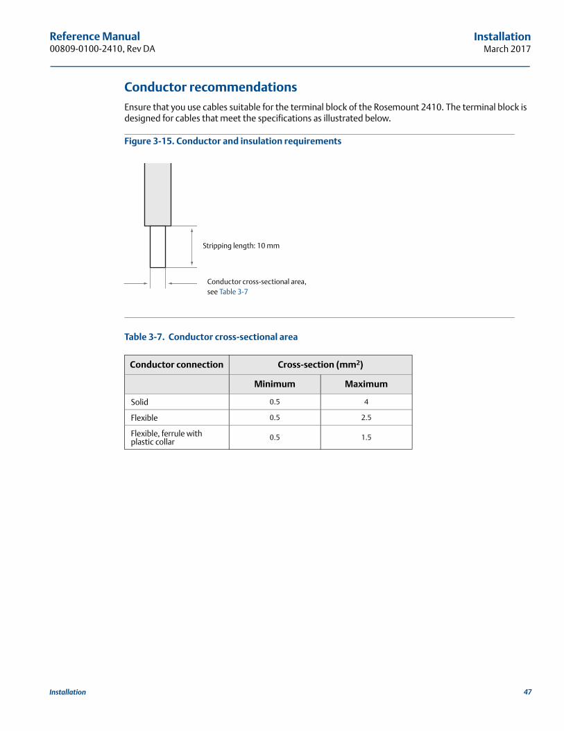
Reference Manual 00809-0100-2410, Rev DA
InstallationMarch 2017
Conductor recommendationsEnsure that you use cables suitable for the terminal block of the Rosemount 2410. The terminal block is designed for cables that meet the specifications as illustrated below.
Figure 3-15. Conductor and insulation requirements
Table 3-7. Conductor cross-sectional area
Conductor connection Cross-section (mm2)
Minimum Maximum
Solid 0.5 4
Flexible 0.5 2.5
Flexible, ferrule with plastic collar 0.5 1.5
Stripping length: 10 mm
Conductor cross-sectional area,see Table 3-7
47Installation
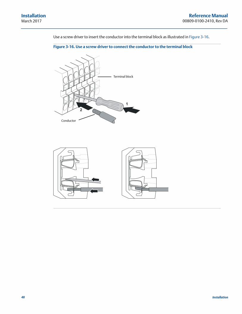
Reference Manual00809-0100-2410, Rev DA
InstallationMarch 2017
Use a screw driver to insert the conductor into the terminal block as illustrated in Figure 3-16.
Figure 3-16. Use a screw driver to connect the conductor to the terminal block
21
Conductor
Terminal block
48 Installation
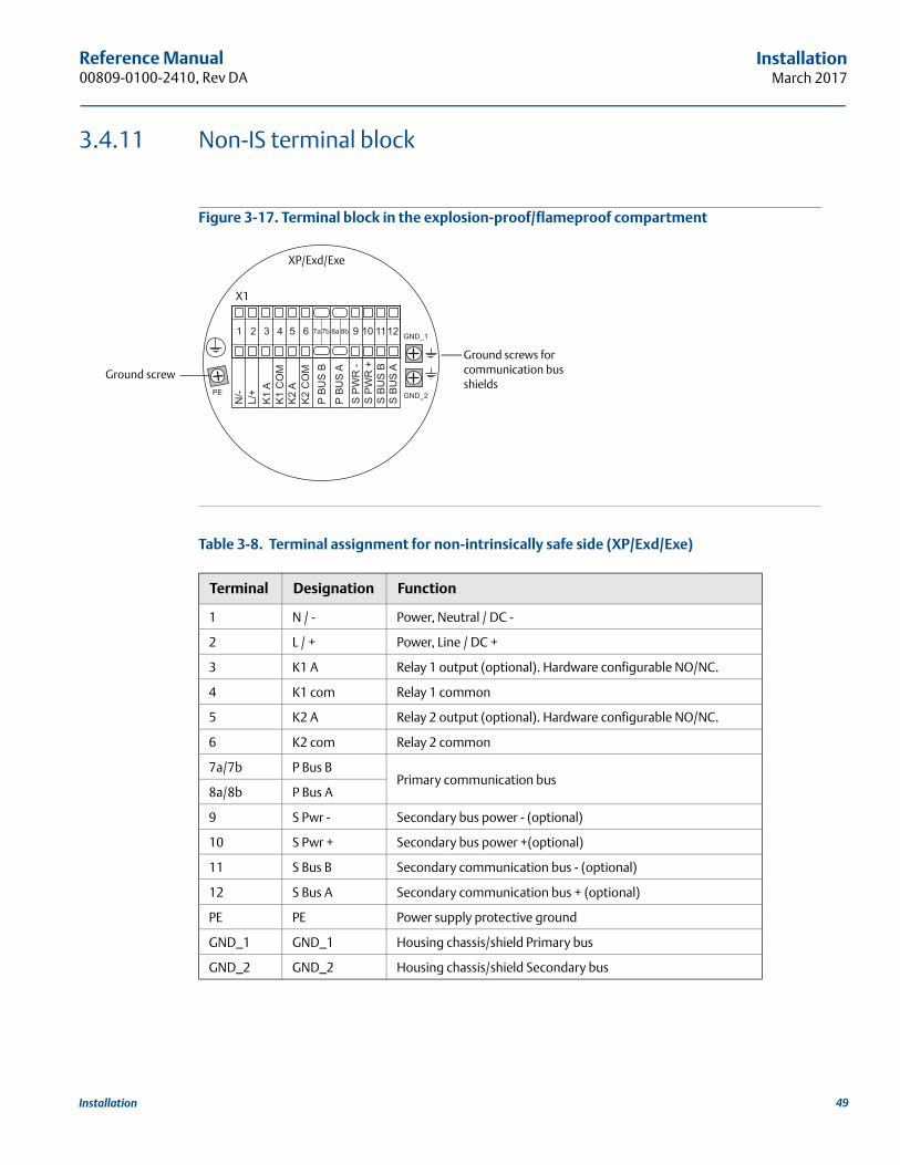
Reference Manual 00809-0100-2410, Rev DA
InstallationMarch 2017
3.4.11 Non-IS terminal block
Figure 3-17. Terminal block in the explosion-proof/flameproof compartment
Table 3-8. Terminal assignment for non-intrinsically safe side (XP/Exd/Exe)
Terminal Designation Function
1 N / - Power, Neutral / DC -
2 L / + Power, Line / DC +
3 K1 A Relay 1 output (optional). Hardware configurable NO/NC.
4 K1 com Relay 1 common
5 K2 A Relay 2 output (optional). Hardware configurable NO/NC.
6 K2 com Relay 2 common
7a/7b P Bus BPrimary communication bus
8a/8b P Bus A
9 S Pwr - Secondary bus power - (optional)
10 S Pwr + Secondary bus power +(optional)
11 S Bus B Secondary communication bus - (optional)
12 S Bus A Secondary communication bus + (optional)
PE PE Power supply protective ground
GND_1 GND_1 Housing chassis/shield Primary bus
GND_2 GND_2 Housing chassis/shield Secondary bus
Ground screws for communication bus shields
Ground screw
X1
XP/Exd/Exe
49Installation
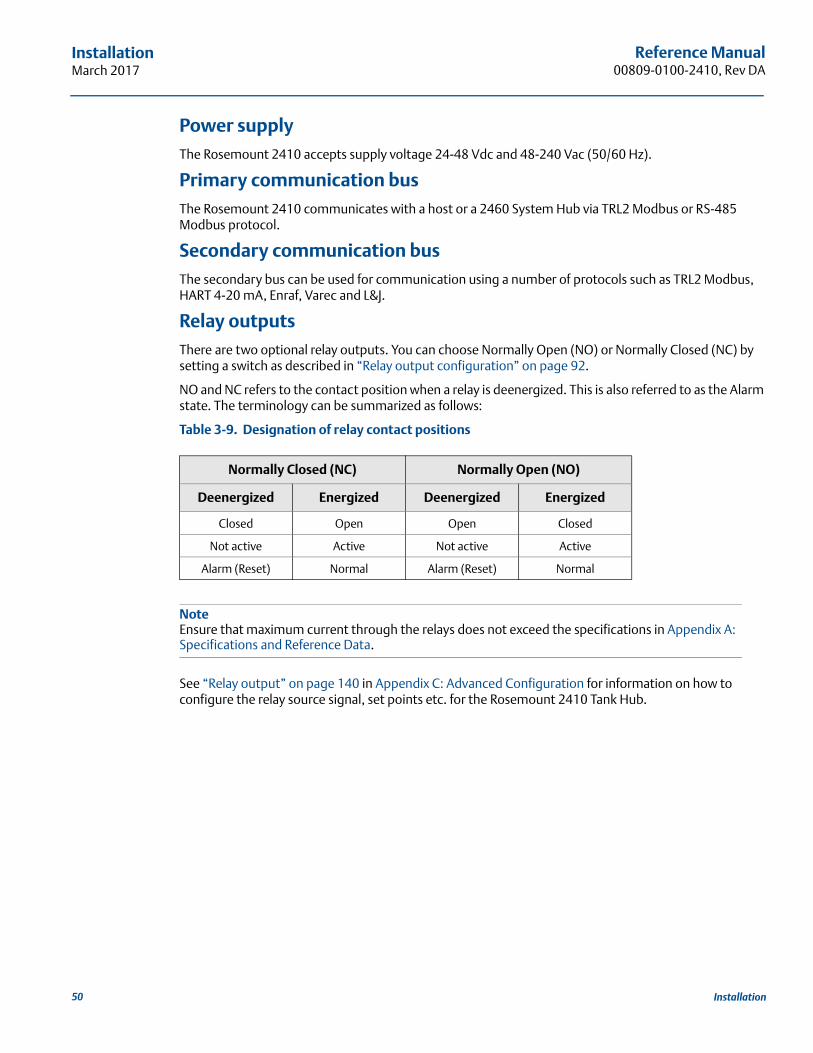
Reference Manual00809-0100-2410, Rev DA
InstallationMarch 2017
Power supplyThe Rosemount 2410 accepts supply voltage 24-48 Vdc and 48-240 Vac (50/60 Hz).
Primary communication busThe Rosemount 2410 communicates with a host or a 2460 System Hub via TRL2 Modbus or RS-485 Modbus protocol.
Secondary communication busThe secondary bus can be used for communication using a number of protocols such as TRL2 Modbus, HART 4-20 mA, Enraf, Varec and L&J.
Relay outputsThere are two optional relay outputs. You can choose Normally Open (NO) or Normally Closed (NC) by setting a switch as described in “Relay output configuration” on page 92.
NO and NC refers to the contact position when a relay is deenergized. This is also referred to as the Alarm state. The terminology can be summarized as follows:
Table 3-9. Designation of relay contact positions
NoteEnsure that maximum current through the relays does not exceed the specifications in Appendix A: Specifications and Reference Data.
See “Relay output” on page 140 in Appendix C: Advanced Configuration for information on how to configure the relay source signal, set points etc. for the Rosemount 2410 Tank Hub.
Normally Closed (NC) Normally Open (NO)
Deenergized Energized Deenergized Energized
Closed Open Open Closed
Not active Active Not active Active
Alarm (Reset) Normal Alarm (Reset) Normal
50 Installation
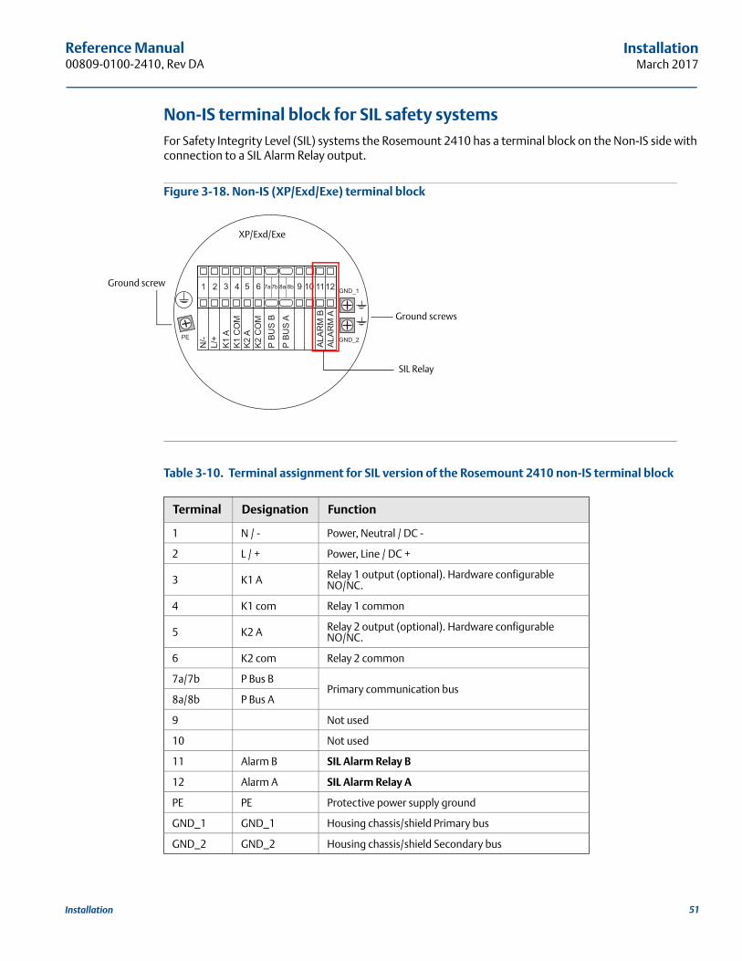
Reference Manual 00809-0100-2410, Rev DA
InstallationMarch 2017
Non-IS terminal block for SIL safety systemsFor Safety Integrity Level (SIL) systems the Rosemount 2410 has a terminal block on the Non-IS side with connection to a SIL Alarm Relay output.
Figure 3-18. Non-IS (XP/Exd/Exe) terminal block
Table 3-10. Terminal assignment for SIL version of the Rosemount 2410 non-IS terminal block
Terminal Designation Function
1 N / - Power, Neutral / DC -
2 L / + Power, Line / DC +
3 K1 A Relay 1 output (optional). Hardware configurable NO/NC.
4 K1 com Relay 1 common
5 K2 A Relay 2 output (optional). Hardware configurable NO/NC.
6 K2 com Relay 2 common
7a/7b P Bus BPrimary communication bus
8a/8b P Bus A
9 Not used
10 Not used
11 Alarm B SIL Alarm Relay B
12 Alarm A SIL Alarm Relay A
PE PE Protective power supply ground
GND_1 GND_1 Housing chassis/shield Primary bus
GND_2 GND_2 Housing chassis/shield Secondary bus
Ground screws
Ground screw
SIL Relay
XP/Exd/Exe
51Installation
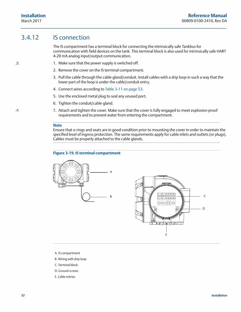
Reference Manual00809-0100-2410, Rev DA
InstallationMarch 2017
3.4.12 IS connectionThe IS compartment has a terminal block for connecting the intrinsically safe Tankbus for communication with field devices on the tank. This terminal block is also used for intrinsically safe HART 4-20 mA analog input/output communication.
1. Make sure that the power supply is switched off.
2. Remove the cover on the IS terminal compartment.
3. Pull the cable through the cable gland/conduit. Install cables with a drip loop in such a way that the lower part of the loop is under the cable/conduit entry.
4. Connect wires according to Table 3-11 on page 53.
5. Use the enclosed metal plug to seal any unused port.
6. Tighten the conduit/cable gland.
7. Attach and tighten the cover. Make sure that the cover is fully engaged to meet explosion-proof requirements and to prevent water from entering the compartment.
NoteEnsure that o-rings and seats are in good condition prior to mounting the cover in order to maintain the specified level of ingress protection. The same requirements apply for cable inlets and outlets (or plugs). Cables must be properly attached to the cable glands.
Figure 3-19. IS terminal compartment
A. IS compartment
B. Wiring with drip loop
C. Terminal block
D. Ground screws
E. Cable entries
C
E
A
D
B
52 Installation
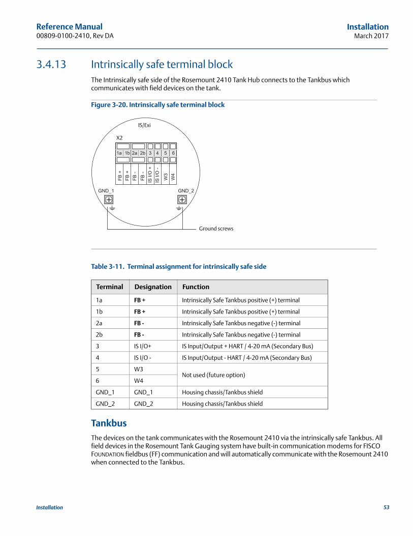
Reference Manual 00809-0100-2410, Rev DA
InstallationMarch 2017
3.4.13 Intrinsically safe terminal blockThe Intrinsically safe side of the Rosemount 2410 Tank Hub connects to the Tankbus which communicates with field devices on the tank.
Figure 3-20. Intrinsically safe terminal block
Table 3-11. Terminal assignment for intrinsically safe side
TankbusThe devices on the tank communicates with the Rosemount 2410 via the intrinsically safe Tankbus. All field devices in the Rosemount Tank Gauging system have built-in communication modems for FISCO FOUNDATION fieldbus (FF) communication and will automatically communicate with the Rosemount 2410 when connected to the Tankbus.
Terminal Designation Function
1a FB + Intrinsically Safe Tankbus positive (+) terminal
1b FB + Intrinsically Safe Tankbus positive (+) terminal
2a FB - Intrinsically Safe Tankbus negative (-) terminal
2b FB - Intrinsically Safe Tankbus negative (-) terminal
3 IS I/O+ IS Input/Output + HART / 4-20 mA (Secondary Bus)
4 IS I/O - IS Input/Output - HART / 4-20 mA (Secondary Bus)
5 W3Not used (future option)
6 W4
GND_1 GND_1 Housing chassis/Tankbus shield
GND_2 GND_2 Housing chassis/Tankbus shield
Ground screws
X2
IS/Exi
53Installation
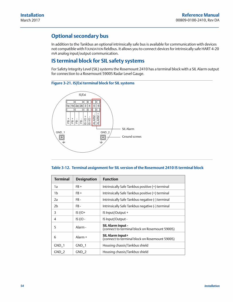
Reference Manual00809-0100-2410, Rev DA
InstallationMarch 2017
Optional secondary busIn addition to the Tankbus an optional intrinsically safe bus is available for communication with devices not compatible with FOUNDATION fieldbus. It allows you to connect devices for intrinsically safe HART 4-20 mA analog input/output communication.
IS terminal block for SIL safety systemsFor Safety Integrity Level (SIL) systems the Rosemount 2410 has a terminal block with a SIL Alarm output for connection to a Rosemount 5900S Radar Level Gauge.
Figure 3-21. IS/Exi terminal block for SIL systems
Table 3-12. Terminal assignment for SIL version of the Rosemount 2410 IS terminal block
Terminal Designation Function
1a FB + Intrinsically Safe Tankbus positive (+) terminal
1b FB + Intrinsically Safe Tankbus positive (+) terminal
2a FB - Intrinsically Safe Tankbus negative (-) terminal
2b FB - Intrinsically Safe Tankbus negative (-) terminal
3 IS I/O+ IS Input/Output +
4 IS I/O - IS Input/Output -
5 Alarm - SIL Alarm input -(connect to terminal block on Rosemount 5900S)
6 Alarm + SIL Alarm input+(connect to terminal block on Rosemount 5900S)
GND_1 GND_1 Housing chassis/Tankbus shield
GND_2 GND_2 Housing chassis/Tankbus shield
Ground screws
SIL Alarm
IS/Exi
54 Installation
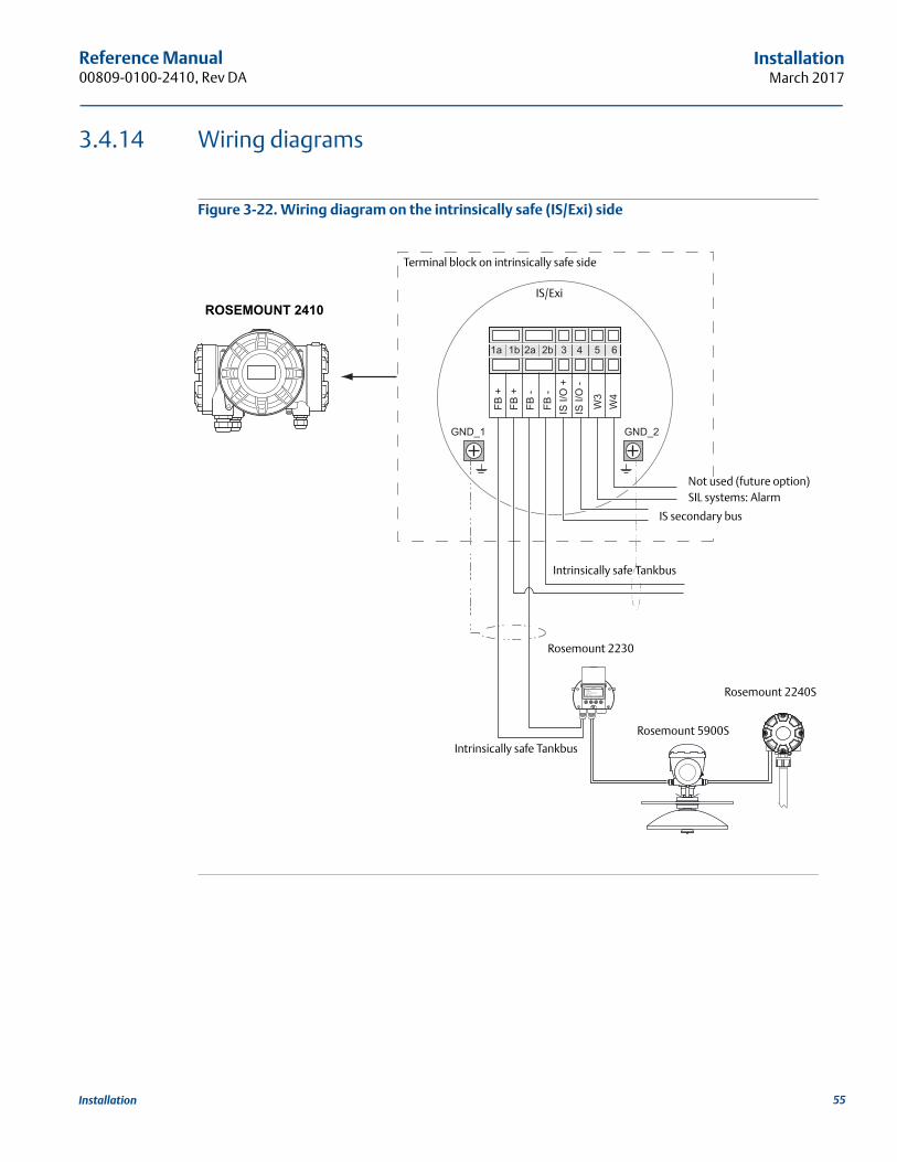
Reference Manual 00809-0100-2410, Rev DA
InstallationMarch 2017
3.4.14 Wiring diagrams
Figure 3-22. Wiring diagram on the intrinsically safe (IS/Exi) side
ROSEMOUNT 2410
Rosemount 5900S
Rosemount 2240S
Terminal block on intrinsically safe side
Rosemount 2230
Not used (future option)SIL systems: Alarm
Intrinsically safe Tankbus
IS/Exi
IS secondary bus
Intrinsically safe Tankbus
55Installation
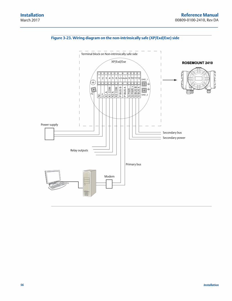
Reference Manual00809-0100-2410, Rev DA
InstallationMarch 2017
Figure 3-23. Wiring diagram on the non-intrinsically safe (XP/Exd/Exe) side
Relay outputs
Power supply
Modem
ROSEMOUNT 2410
Secondary bus
Primary bus
Terminal block on Non-intrinsically safe side
ROSEMOUNT 2410XP/Exd/Exe
Secondary power
56 Installation
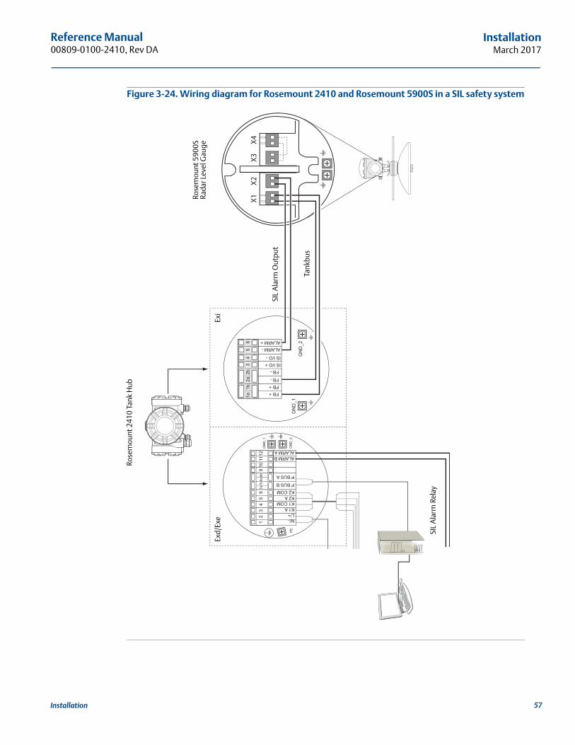
Reference Manual 00809-0100-2410, Rev DA
InstallationMarch 2017
Figure 3-24. Wiring diagram for Rosemount 2410 and Rosemount 5900S in a SIL safety system
Rose
mou
nt 5
900S
Rada
r Lev
el G
auge
Rose
mou
nt 2
410
Tank
Hub
SIL
Ala
rm R
elay
SIL
Ala
rm O
utpu
t
Tank
bus
Exi
Exd/
Exe
57Installation

Reference Manual00809-0100-2410, Rev DA
InstallationMarch 2017
58 Installation
Reference Manual 00809-0100-2410, Rev DA
ConfigurationMarch 2017
Section 4 Configuration
Safety messages . . . . . . . . . . . . . . . . . . . . . . . . . . . . . . . . . . . . . . . . . . . . . . . . . . . . . . . . . . . . . . . . . . page 59Introduction . . . . . . . . . . . . . . . . . . . . . . . . . . . . . . . . . . . . . . . . . . . . . . . . . . . . . . . . . . . . . . . . . . . . . page 60Configuration tools . . . . . . . . . . . . . . . . . . . . . . . . . . . . . . . . . . . . . . . . . . . . . . . . . . . . . . . . . . . . . . . page 60Basic configuration of a Rosemount 2410 Tank Hub . . . . . . . . . . . . . . . . . . . . . . . . . . . . . . . . . . . page 61Advanced configuration . . . . . . . . . . . . . . . . . . . . . . . . . . . . . . . . . . . . . . . . . . . . . . . . . . . . . . . . . . . page 62Configuration using TankMaster WinSetup . . . . . . . . . . . . . . . . . . . . . . . . . . . . . . . . . . . . . . . . . . . page 62
4.1 Safety messagesProcedures and instructions in this section may require special precautions to ensure the safety of the personnel performing the operations. Information that raises potential safety issues is indicated by a
warning symbol ( ). Please refer to the following safety messages before performing an operation preceded by this symbol.
Failure to follow safe installation and servicing guidelines could result in death or serious injury:
Make sure only qualified personnel perform the installation.
Use the equipment only as specified in this manual. Failure to do so may impair the protection provided by the equipment.
Do not perform any service other than those contained in this manual unless you are qualified.
Explosions could result in death or serious injury:
Verify that the operating environment of the device is consistent with the appropriate hazardous locations certifications.
Before connecting a communicator in an explosive atmosphere, make sure the instruments in the loop are installed in accordance with intrinsically safe or non-incendive field wiring practices.
Do not remove the gauge cover in explosive atmospheres when the circuit is alive.
59Configuration
Reference Manual00809-0100-2410, Rev DA
ConfigurationMarch 2017
4.2 IntroductionA Rosemount™ Tank Gauging system includes a wide range of devices for tank monitoring. It is a flexible and scalable system which can be adapted to various applications and small or large tank farms. A typical system includes one or more of the following devices:
control room PC with Rosemount TankMaster program for operational control
Rosemount 2460 System Hub that collects measurement data from Rosemount 2410 Tank Hubs
Rosemount 2410 Tank Hub which collects measurement data from field devices on the tanks
various field instruments such as the Rosemount 5900S Radar Level Gauge, Rosemount 2240S Multi-input Temperature Transmitter, Rosemount 2230 Graphical Field Display, Rosemount 3051S Pressure Transmitter
Emerson Wireless Gateway and Emerson Wireless THUM Adapter for wireless communication between field devices and control room host system
See the Rosemount Tank Gauging System Data Sheet (Document no. 00813-0100-5100) for a comprehensive description of the components in a Rosemount Tank Gauging system.
4.3 Configuration toolsThe Rosemount 2410 Tank Hub is configured by using the Rosemount TankMaster Winsetup configuration program. Winsetup is a user-friendly software package that includes basic configuration options as well as advanced configuration and service functions.
See the Rosemount Tank Gauging System Configuration Manual (Document no. 00809-0300-5100) for more information on how to use the TankMaster WinSetup software to configure the Rosemount 2410 Tank Hub.
See also the Rosemount Wireless TankGauging System reference manual (Document no. 00809-0100-5200) for information on how to set up a Rosemount 2410 in a WirelessHART® system.
60 Configuration
Reference Manual 00809-0100-2410, Rev DA
ConfigurationMarch 2017
4.4 Basic configuration of a Rosemount 2410 Tank HubThis is a general description of how to configure a Rosemount 2410 Tank Hub. The Rosemount Tank Gauging System Configuration Manual (Document no. 00809-0300-5100) provides a detailed description of how to use the Rosemount TankMaster WinSetup program as a configuration tool for the Rosemount 2410.
CommunicationDepending on the particular system configuration, a Rosemount 2410 Tank Hub may communicate directly with a host computer or via a Rosemount 2460 System Hub.
In case the Rosemount 2410 is connected to a Rosemount 2460 System Hub, you will have to specify which communication protocol channel to be used.
The Rosemount 2410 has default Modbus® adress=247. The address should be changed to the recommended address range. The Modbus address must match the address specified in the Rosemount 2460’s tank database.
The Rosemount 2410 Tank Hub can be used in a WirelessHART system by connecting an Emerson Wireless THUM™ Adapter. The THUM adapter allows the Rosemount 2410 to communicate with a host system via an Emerson Wireless Gateway.
Tank databaseThe Rosemount 2410 has a tank database that maps field devices to tanks. It also stores Modbus addresses of level gauges and auxiliary tank devices (ATD) such as the Rosemount 2240S Multi-input Temperature Transmitter. The Modbus addresses are used for communication with Rosemount 2460 System Hub and host computers.
Device tagsFor each tank, device tags are specified for the level gauge and the auxiliary tank devices (ATD). ATD devices include all instruments on the tank except the level gauge. Device tags are used as identifiers in TankMaster.
Integral displayThe Rosemount 2410 can be configured to present measurement data on the optional integral display. The display alternates between the selected items at a rate given by the Display Toggle Time parameter.
Measurement data such as Level, Level Rate, Free Water Level and many other tank variables can be displayed.
Measurement units for Level, Level Rate, Volume, Temperature, Density, and Pressure can be specified regardless of which units are used for presentation in, for example, the TankMaster programs.
61Configuration
Reference Manual00809-0100-2410, Rev DA
ConfigurationMarch 2017
4.5 Advanced configurationThe installation wizard in TankMaster Winsetup comprises a basic configuration of the Rosemount 2410. There are more options available in case further configuration is needed:
Primary/Secondary Bus configuration
Up to ten “virtual” Relay Functions
Hybrid Density
Delta Level
Analog Output
Analog Input / HART Slave(1)
See Appendix C: Advanced Configuration for more information.
4.6 Configuration using TankMaster WinSetupA Rosemount 2410 Tank Hub can easily be installed and configured by using the TankMaster Winsetup configuration program. The WinSetup installation wizard guides you through the basic configuration needed for starting up a Rosemount 2410.
See the Rosemount Tank Gauging System Configuration Manual (Document no. 00809-0300-5100) for more information on using the TankMaster WinSetup software to configure a Rosemount Tank Gauging system and a Rosemount 2410 Tank Hub.
See also the Rosemount TankGauging Wireless System Reference Manual (Document no. 00809-0100-5200) for information on how to set up a WirelessHART system.
1, Analog Input and HART Slave functions are configured in the Properties window of Auxiliary Tank Device (ATD), see “Configuration of analog input / HART® slave device” on page 160.
62 Configuration
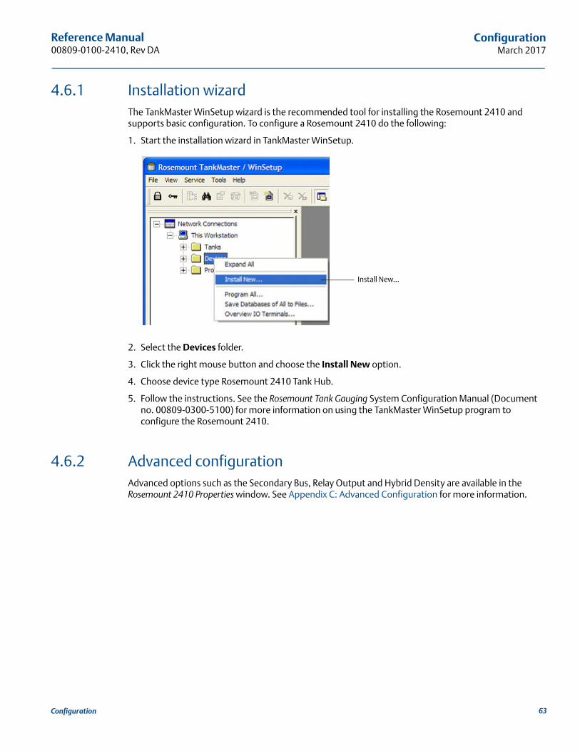
Reference Manual 00809-0100-2410, Rev DA
ConfigurationMarch 2017
4.6.1 Installation wizardThe TankMaster WinSetup wizard is the recommended tool for installing the Rosemount 2410 and supports basic configuration. To configure a Rosemount 2410 do the following:
1. Start the installation wizard in TankMaster WinSetup.
2. Select the Devices folder.
3. Click the right mouse button and choose the Install New option.
4. Choose device type Rosemount 2410 Tank Hub.
5. Follow the instructions. See the Rosemount Tank Gauging System Configuration Manual (Document no. 00809-0300-5100) for more information on using the TankMaster WinSetup program to configure the Rosemount 2410.
4.6.2 Advanced configurationAdvanced options such as the Secondary Bus, Relay Output and Hybrid Density are available in the Rosemount 2410 Properties window. See Appendix C: Advanced Configuration for more information.
Install New...
63Configuration
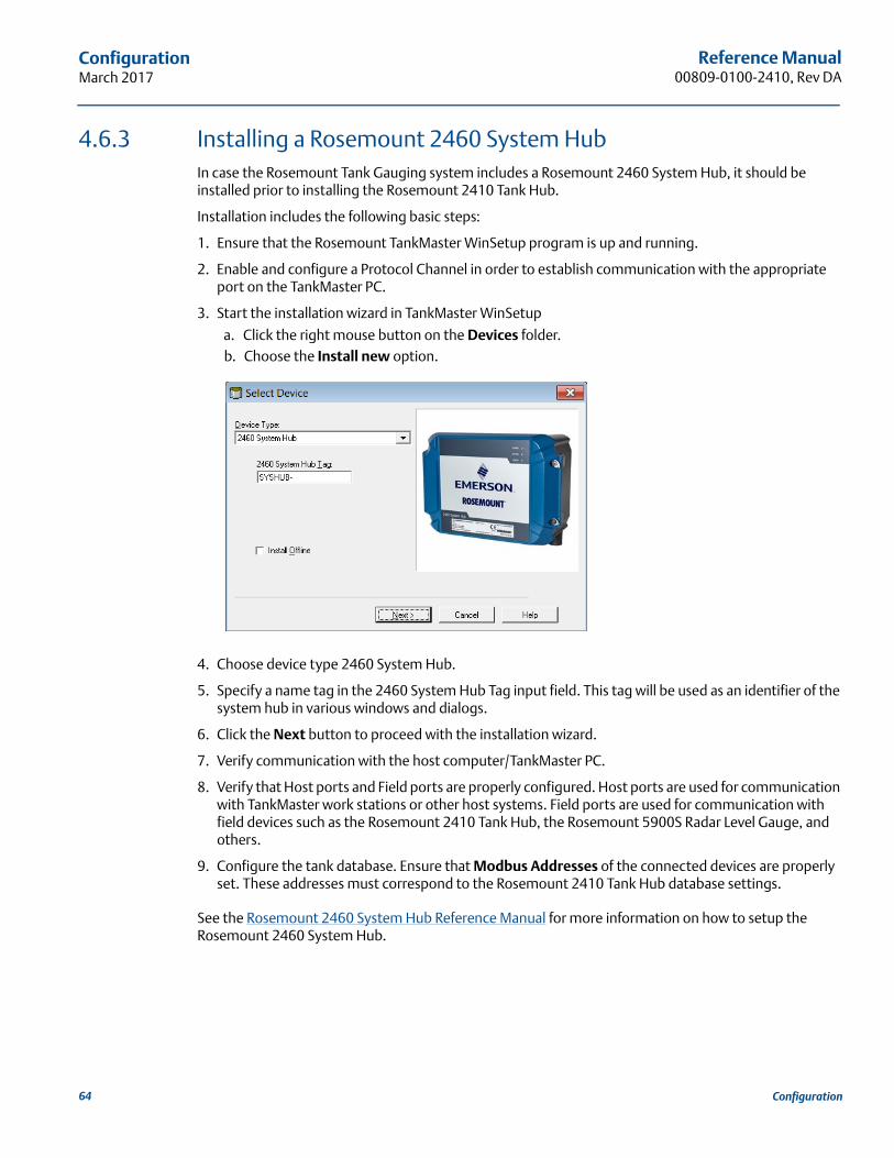
Reference Manual00809-0100-2410, Rev DA
ConfigurationMarch 2017
4.6.3 Installing a Rosemount 2460 System HubIn case the Rosemount Tank Gauging system includes a Rosemount 2460 System Hub, it should be installed prior to installing the Rosemount 2410 Tank Hub.
Installation includes the following basic steps:
1. Ensure that the Rosemount TankMaster WinSetup program is up and running.
2. Enable and configure a Protocol Channel in order to establish communication with the appropriate port on the TankMaster PC.
3. Start the installation wizard in TankMaster WinSetup
a. Click the right mouse button on the Devices folder.b. Choose the Install new option.
4. Choose device type 2460 System Hub.
5. Specify a name tag in the 2460 System Hub Tag input field. This tag will be used as an identifier of the system hub in various windows and dialogs.
6. Click the Next button to proceed with the installation wizard.
7. Verify communication with the host computer/TankMaster PC.
8. Verify that Host ports and Field ports are properly configured. Host ports are used for communication with TankMaster work stations or other host systems. Field ports are used for communication with field devices such as the Rosemount 2410 Tank Hub, the Rosemount 5900S Radar Level Gauge, and others.
9. Configure the tank database. Ensure that Modbus Addresses of the connected devices are properly set. These addresses must correspond to the Rosemount 2410 Tank Hub database settings.
See the Rosemount 2460 System Hub Reference Manual for more information on how to setup the Rosemount 2460 System Hub.
64 Configuration
Reference Manual 00809-0100-2410, Rev DA
OperationMarch 2017
Section 5 Operation
Safety messages . . . . . . . . . . . . . . . . . . . . . . . . . . . . . . . . . . . . . . . . . . . . . . . . . . . . . . . . . . . . . . . . . . page 65Integral display . . . . . . . . . . . . . . . . . . . . . . . . . . . . . . . . . . . . . . . . . . . . . . . . . . . . . . . . . . . . . . . . . . . page 66Error messages . . . . . . . . . . . . . . . . . . . . . . . . . . . . . . . . . . . . . . . . . . . . . . . . . . . . . . . . . . . . . . . . . . . page 69LED . . . . . . . . . . . . . . . . . . . . . . . . . . . . . . . . . . . . . . . . . . . . . . . . . . . . . . . . . . . . . . . . . . . . . . . . . . . . . page 70Specifying display variables . . . . . . . . . . . . . . . . . . . . . . . . . . . . . . . . . . . . . . . . . . . . . . . . . . . . . . . . page 74
5.1 Safety messagesProcedures and instructions in this section may require special precautions to ensure the safety of the personnel performing the operations. Information that raises potential safety issues is indicated by a
warning symbol ( ). Please refer to the following safety messages before performing an operation preceded by this symbol.
Failure to follow safe installation and servicing guidelines could result in death or serious injury:
Make sure only qualified personnel perform the installation.
Use the equipment only as specified in this manual. Failure to do so may impair the protection provided by the equipment.
Do not perform any service other than those contained in this manual unless you are qualified.
Explosions could result in death or serious injury:
Verify that the operating environment of the device is consistent with the appropriate hazardous locations certifications.
Before connecting a communicator in an explosive atmosphere, make sure the instruments in the loop are installed in accordance with intrinsically safe or non-incendive field wiring practices.
Do not remove the gauge cover in explosive atmospheres when the circuit is alive.
65Operation
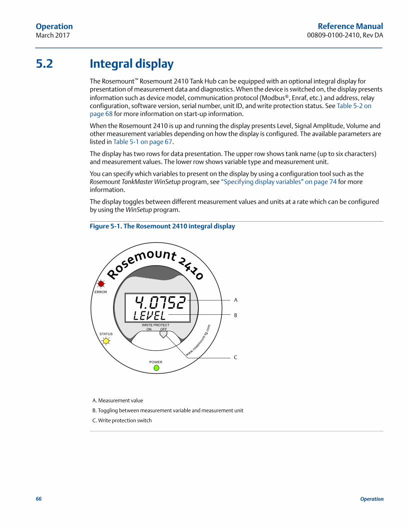
Reference Manual00809-0100-2410, Rev DA
OperationMarch 2017
5.2 Integral displayThe Rosemount™ Rosemount 2410 Tank Hub can be equipped with an optional integral display for presentation of measurement data and diagnostics. When the device is switched on, the display presents information such as device model, communication protocol (Modbus®, Enraf, etc.) and address, relay configuration, software version, serial number, unit ID, and write protection status. See Table 5-2 on page 68 for more information on start-up information.
When the Rosemount 2410 is up and running the display presents Level, Signal Amplitude, Volume and other measurement variables depending on how the display is configured. The available parameters are listed in Table 5-1 on page 67.
The display has two rows for data presentation. The upper row shows tank name (up to six characters) and measurement values. The lower row shows variable type and measurement unit.
You can specify which variables to present on the display by using a configuration tool such as the Rosemount TankMaster WinSetup program, see “Specifying display variables” on page 74 for more information.
The display toggles between different measurement values and units at a rate which can be configured by using the WinSetup program.
Figure 5-1. The Rosemount 2410 integral display
A. Measurement value
B. Toggling between measurement variable and measurement unit
C. Write protection switch
A
B
C
66 Operation
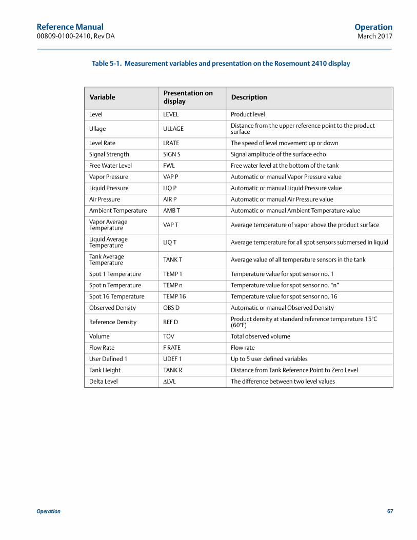
Reference Manual 00809-0100-2410, Rev DA
OperationMarch 2017
Table 5-1. Measurement variables and presentation on the Rosemount 2410 display
VariablePresentation on display
Description
Level LEVEL Product level
Ullage ULLAGE Distance from the upper reference point to the product surface
Level Rate LRATE The speed of level movement up or down
Signal Strength SIGN S Signal amplitude of the surface echo
Free Water Level FWL Free water level at the bottom of the tank
Vapor Pressure VAP P Automatic or manual Vapor Pressure value
Liquid Pressure LIQ P Automatic or manual Liquid Pressure value
Air Pressure AIR P Automatic or manual Air Pressure value
Ambient Temperature AMB T Automatic or manual Ambient Temperature value
Vapor Average Temperature VAP T Average temperature of vapor above the product surface
Liquid Average Temperature LIQ T Average temperature for all spot sensors submersed in liquid
Tank Average Temperature TANK T Average value of all temperature sensors in the tank
Spot 1 Temperature TEMP 1 Temperature value for spot sensor no. 1
Spot n Temperature TEMP n Temperature value for spot sensor no. “n”
Spot 16 Temperature TEMP 16 Temperature value for spot sensor no. 16
Observed Density OBS D Automatic or manual Observed Density
Reference Density REF D Product density at standard reference temperature 15°C (60°F)
Volume TOV Total observed volume
Flow Rate F RATE Flow rate
User Defined 1 UDEF 1 Up to 5 user defined variables
Tank Height TANK R Distance from Tank Reference Point to Zero Level
Delta Level LVL The difference between two level values
67Operation
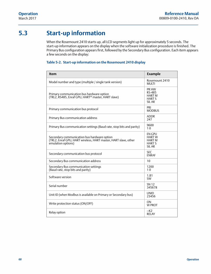
Reference Manual00809-0100-2410, Rev DA
OperationMarch 2017
5.3 Start-up informationWhen the Rosemount 2410 starts up, all LCD segments light up for approximately 5 seconds. The start-up information appears on the display when the software initialization procedure is finished. The Primary Bus configuration appears first, followed by the Secondary Bus configuration. Each item appears a few seconds on the display:
Table 5-2. Start-up information on the Rosemount 2410 display
Item Example
Model number and type (multiple / single tank version) Rosemount 2410 MULTI
Primary communication bus hardware option (TRL2, RS485, Enraf GPU, HART® master, HART slave)
PR HW RS-485HART MHART SSIL AR
Primary communication bus protocol PRIMODBUS
Primary Bus communication address ADDR247
Primary Bus communication settings (Baud rate, stop bits and parity) 96001 0
Secondary communication bus hardware option (TRL2, Enraf GPU, HART wireless, HART master, HART slave, other emulation options)
EN GPUHART WHART MHART SSIL AR
Secondary communication bus protocol SECENRAF
Secondary Bus communication address 10
Secondary Bus communication settings (Baud rate, stop bits and parity)
12001 0
Software version 1.B1SW
Serial number SN 12345678
Unit ID (when Modbus is available on Primary or Secondary bus) UNID23456
Write protection status (ON/OFF) ONW PROT
Relay option --K2RELAY
68 Operation
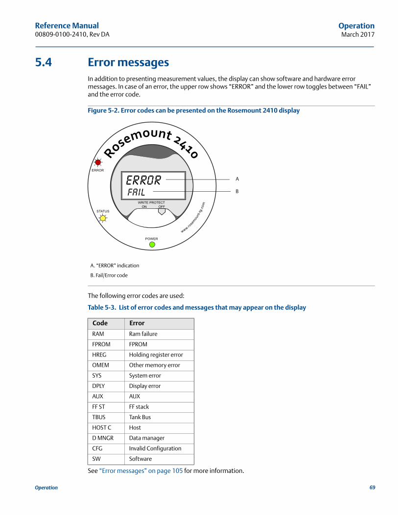
Reference Manual 00809-0100-2410, Rev DA
OperationMarch 2017
5.4 Error messagesIn addition to presenting measurement values, the display can show software and hardware error messages. In case of an error, the upper row shows “ERROR” and the lower row toggles between “FAIL” and the error code.
Figure 5-2. Error codes can be presented on the Rosemount 2410 display
The following error codes are used:
Table 5-3. List of error codes and messages that may appear on the display
See “Error messages” on page 105 for more information.
A. “ERROR” indication
B. Fail/Error code
Code Error
RAM Ram failure
FPROM FPROM
HREG Holding register error
OMEM Other memory error
SYS System error
DPLY Display error
AUX AUX
FF ST FF stack
TBUS Tank Bus
HOST C Host
D MNGR Data manager
CFG Invalid Configuration
SW Software
B
A
69Operation
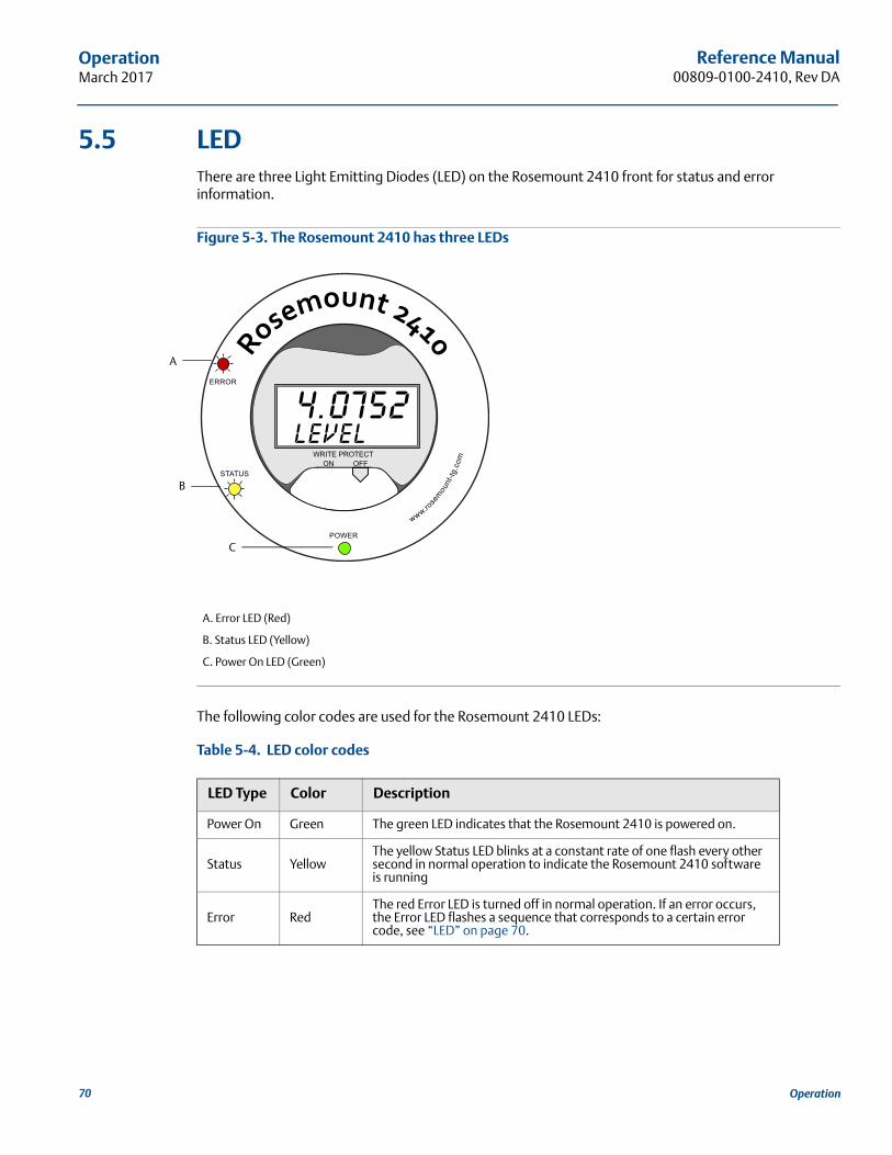
Reference Manual00809-0100-2410, Rev DA
OperationMarch 2017
5.5 LEDThere are three Light Emitting Diodes (LED) on the Rosemount 2410 front for status and error information.
Figure 5-3. The Rosemount 2410 has three LEDs
The following color codes are used for the Rosemount 2410 LEDs:
Table 5-4. LED color codes
A. Error LED (Red)
B. Status LED (Yellow)
C. Power On LED (Green)
LED Type Color Description
Power On Green The green LED indicates that the Rosemount 2410 is powered on.
Status YellowThe yellow Status LED blinks at a constant rate of one flash every other second in normal operation to indicate the Rosemount 2410 software is running
Error RedThe red Error LED is turned off in normal operation. If an error occurs, the Error LED flashes a sequence that corresponds to a certain error code, see “LED” on page 70.
A
B
C
70 Operation
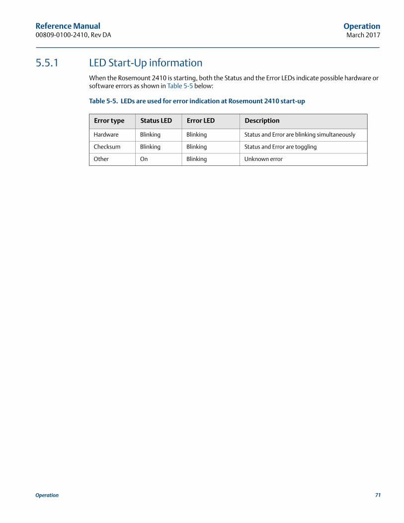
Reference Manual 00809-0100-2410, Rev DA
OperationMarch 2017
5.5.1 LED Start-Up informationWhen the Rosemount 2410 is starting, both the Status and the Error LEDs indicate possible hardware or software errors as shown in Table 5-5 below:
Table 5-5. LEDs are used for error indication at Rosemount 2410 start-up
Error type Status LED Error LED Description
Hardware Blinking Blinking Status and Error are blinking simultaneously
Checksum Blinking Blinking Status and Error are toggling
Other On Blinking Unknown error
71Operation
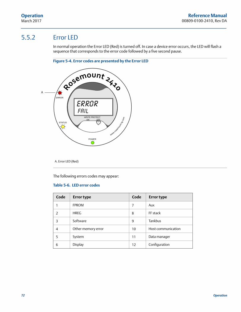
Reference Manual00809-0100-2410, Rev DA
OperationMarch 2017
5.5.2 Error LEDIn normal operation the Error LED (Red) is turned off. In case a device error occurs, the LED will flash a sequence that corresponds to the error code followed by a five second pause.
Figure 5-4. Error codes are presented by the Error LED
The following errors codes may appear:
Table 5-6. LED error codes
A. Error LED (Red)
Code Error type Code Error type
1 FPROM 7 Aux
2 HREG 8 FF stack
3 Software 9 Tankbus
4 Other memory error 10 Host communication
5 System 11 Data manager
6 Display 12 Configuration
A
72 Operation
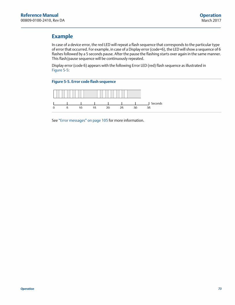
Reference Manual 00809-0100-2410, Rev DA
OperationMarch 2017
ExampleIn case of a device error, the red LED will repeat a flash sequence that corresponds to the particular type of error that occurred. For example, in case of a Display error (code=6), the LED will show a sequence of 6 flashes followed by a 5 seconds pause. After the pause the flashing starts over again in the same manner. This flash/pause sequence will be continuously repeated.
Display error (code 6) appears with the following Error LED (red) flash sequence as illustrated in Figure 5-5:
Figure 5-5. Error code flash sequence
See “Error messages” on page 105 for more information.
Seconds
73Operation
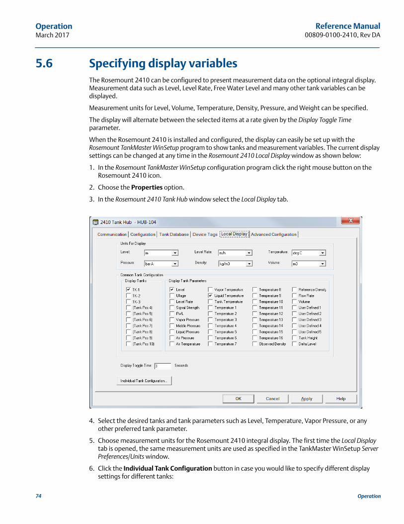
Reference Manual00809-0100-2410, Rev DA
OperationMarch 2017
5.6 Specifying display variablesThe Rosemount 2410 can be configured to present measurement data on the optional integral display. Measurement data such as Level, Level Rate, Free Water Level and many other tank variables can be displayed.
Measurement units for Level, Volume, Temperature, Density, Pressure, and Weight can be specified.
The display will alternate between the selected items at a rate given by the Display Toggle Time parameter.
When the Rosemount 2410 is installed and configured, the display can easily be set up with the Rosemount TankMaster WinSetup program to show tanks and measurement variables. The current display settings can be changed at any time in the Rosemount 2410 Local Display window as shown below:
1. In the Rosemount TankMaster WinSetup configuration program click the right mouse button on the Rosemount 2410 icon.
2. Choose the Properties option.
3. In the Rosemount 2410 Tank Hub window select the Local Display tab.
4. Select the desired tanks and tank parameters such as Level, Temperature, Vapor Pressure, or any other preferred tank parameter.
5. Choose measurement units for the Rosemount 2410 integral display. The first time the Local Display tab is opened, the same measurement units are used as specified in the TankMaster WinSetup Server Preferences/Units window.
6. Click the Individual Tank Configuration button in case you would like to specify different display settings for different tanks:
74 Operation
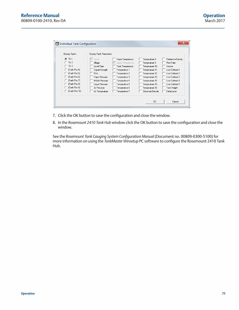
Reference Manual 00809-0100-2410, Rev DA
OperationMarch 2017
7. Click the OK button to save the configuration and close the window.
8. In the Rosemount 2410 Tank Hub window click the OK button to save the configuration and close the window.
See the Rosemount Tank Gauging System Configuration Manual (Document no. 00809-0300-5100) for more information on using the TankMaster Winsetup PC software to configure the Rosemount 2410 Tank Hub.
75Operation

76
Reference Manual00809-0100-2410, Rev DA
OperationMarch 2017
Operation
Reference Manual 00809-0100-2410, Rev DA
Service and TroubleshootingMarch 2017
Section 6 Service and Troubleshooting
Safety messages . . . . . . . . . . . . . . . . . . . . . . . . . . . . . . . . . . . . . . . . . . . . . . . . . . . . . . . . . . . . . . . . . . page 77Service . . . . . . . . . . . . . . . . . . . . . . . . . . . . . . . . . . . . . . . . . . . . . . . . . . . . . . . . . . . . . . . . . . . . . . . . . . page 78Troubleshooting . . . . . . . . . . . . . . . . . . . . . . . . . . . . . . . . . . . . . . . . . . . . . . . . . . . . . . . . . . . . . . . . . . page 95
6.1 Safety messagesProcedures and instructions in this section may require special precautions to ensure the safety of the personnel performing the operations. Information that raises potential safety issues is indicated by a
warning symbol ( ). Please refer to the following safety messages before performing an operation preceded by this symbol.
Failure to follow safe installation and servicing guidelines could result in death or serious injury:
Make sure only qualified personnel perform the installation.
Use the equipment only as specified in this manual. Failure to do so may impair the protection provided by the equipment.
Do not perform any service other than those contained in this manual unless you are qualified.
Explosions could result in death or serious injury:
Verify that the operating environment of the device is consistent with the appropriate hazardous locations certifications.
Before connecting a communicator in an explosive atmosphere, make sure the instruments in the loop are installed in accordance with intrinsically safe or non-incendive field wiring practices.
Do not remove the gauge cover in explosive atmospheres when the circuit is alive.
To prevent ignition of flammable or combustible atmospheres, disconnect power before servicing.y
77Service and Troubleshooting
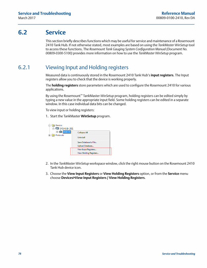
Reference Manual00809-0100-2410, Rev DA
Service and TroubleshootingMarch 2017
6.2 ServiceThis section briefly describes functions which may be useful for service and maintenance of a Rosemount 2410 Tank Hub. If not otherwise stated, most examples are based on using the TankMaster WinSetup tool to access these functions. The Rosemount Tank Gauging System Configuration Manual (Document No. 00809-0300-5100) provides more information on how to use the TankMaster WinSetup program.
6.2.1 Viewing Input and Holding registersMeasured data is continuously stored in the Rosemount 2410 Tank Hub’s input registers. The Input registers allow you to check that the device is working properly.
The holding registers store parameters which are used to configure the Rosemount 2410 for various applications.
By using the Rosemount™ TankMaster WinSetup program, holding registers can be edited simply by typing a new value in the appropriate input field. Some holding registers can be edited in a separate window. In this case individual data bits can be changed.
To view input or holding registers:
1. Start the TankMaster WinSetup program.
2. In the TankMaster WinSetup workspace window, click the right mouse button on the Rosemount 2410 Tank Hub device icon.
3. Choose the View Input Registers or View Holding Registers option, or from the Service menu choose Devices>View Input Registers / View Holding Registers.
78 Service and Troubleshooting
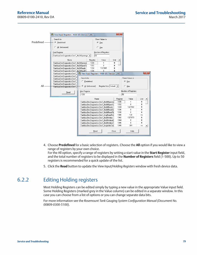
Reference Manual 00809-0100-2410, Rev DA
Service and TroubleshootingMarch 2017
4. Choose Predefined for a basic selection of registers. Choose the All option if you would like to view a range of registers by your own choice.For the All option, specify a range of registers by setting a start value in the Start Register input field, and the total number of registers to be displayed in the Number of Registers field (1-500). Up to 50 registers is recommended for a quick update of the list.
5. Click the Read button to update the View Input/Holding Registers window with fresh device data.
6.2.2 Editing Holding registersMost Holding Registers can be edited simply by typing a new value in the appropriate Value input field. Some Holding Registers (marked grey in the Value column) can be edited in a separate window. In this case you can choose from a list of options or you can change separate data bits.
For more information see the Rosemount Tank Gauging System Configuration Manual (Document No. 00809-0300-5100).
Predefined
All
79Service and Troubleshooting
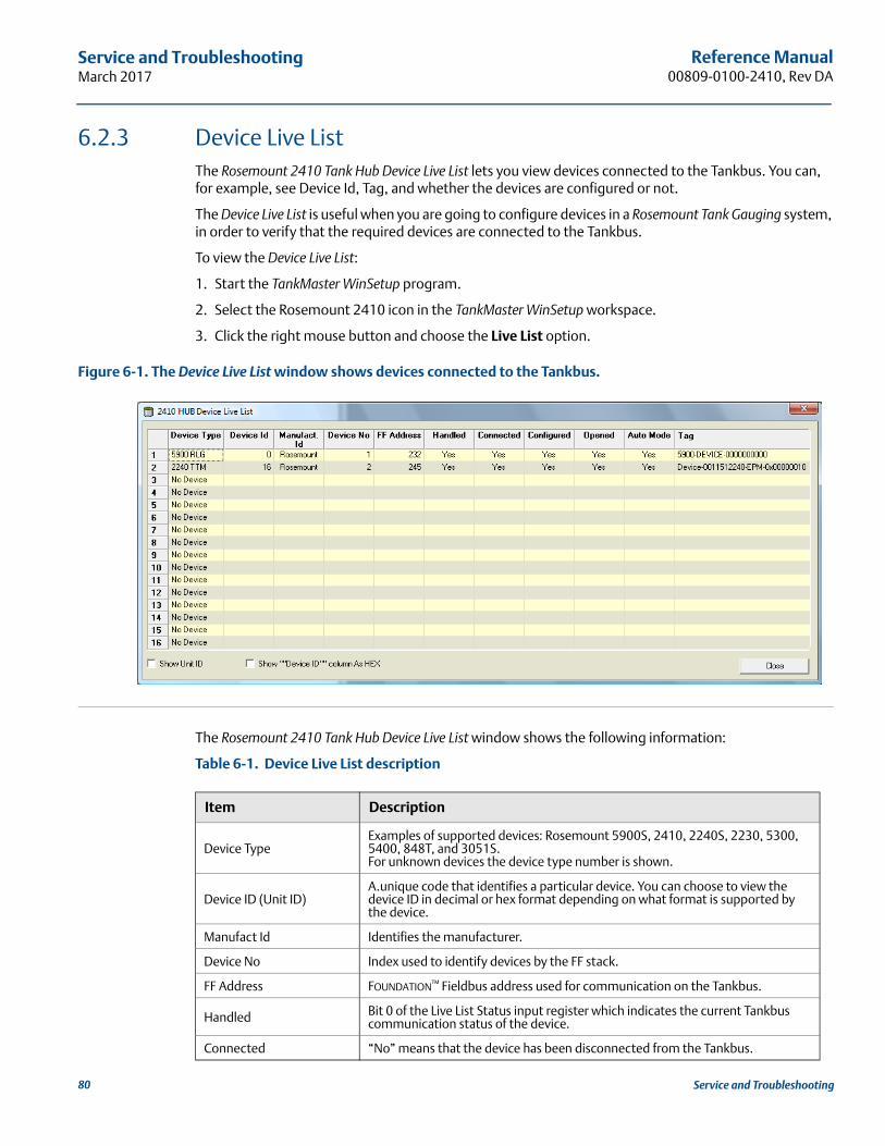
Reference Manual00809-0100-2410, Rev DA
Service and TroubleshootingMarch 2017
6.2.3 Device Live ListThe Rosemount 2410 Tank Hub Device Live List lets you view devices connected to the Tankbus. You can, for example, see Device Id, Tag, and whether the devices are configured or not.
The Device Live List is useful when you are going to configure devices in a Rosemount Tank Gauging system, in order to verify that the required devices are connected to the Tankbus.
To view the Device Live List:
1. Start the TankMaster WinSetup program.
2. Select the Rosemount 2410 icon in the TankMaster WinSetup workspace.
3. Click the right mouse button and choose the Live List option.
Figure 6-1. The Device Live List window shows devices connected to the Tankbus.
The Rosemount 2410 Tank Hub Device Live List window shows the following information:
Table 6-1. Device Live List description
Item Description
Device TypeExamples of supported devices: Rosemount 5900S, 2410, 2240S, 2230, 5300, 5400, 848T, and 3051S. For unknown devices the device type number is shown.
Device ID (Unit ID) A.unique code that identifies a particular device. You can choose to view the device ID in decimal or hex format depending on what format is supported by the device.
Manufact Id Identifies the manufacturer.
Device No Index used to identify devices by the FF stack.
FF Address FOUNDATION™ Fieldbus address used for communication on the Tankbus.
Handled Bit 0 of the Live List Status input register which indicates the current Tankbus communication status of the device.
Connected “No” means that the device has been disconnected from the Tankbus.
80 Service and Troubleshooting
Reference Manual 00809-0100-2410, Rev DA
Service and TroubleshootingMarch 2017
Configured “Yes” indicates that the device is configured in the Rosemount 2410 tank database, i.e. the device is mapped to a particular tank.
Opened Bit 1 of the Live List Status input register which indicates the current Tankbus communication status of the device.
Auto Mode “Yes” in normal operation. “No” indicates that the device is in Out of Service mode.
TagA removable tag provided with the device lets you identify the device to a physical location. This field shows the Tag number of the device (when available).
Item Description
81Service and Troubleshooting
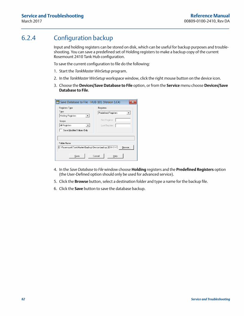
Reference Manual00809-0100-2410, Rev DA
Service and TroubleshootingMarch 2017
6.2.4 Configuration backupInput and holding registers can be stored on disk, which can be useful for backup purposes and trouble-shooting. You can save a predefined set of Holding registers to make a backup copy of the current Rosemount 2410 Tank Hub configuration.
To save the current configuration to file do the following:
1. Start the TankMaster WinSetup program.
2. In the TankMaster WinSetup workspace window, click the right mouse button on the device icon.
3. Choose the Devices/Save Database to File option, or from the Service menu choose Devices/Save Database to File.
4. In the Save Database to File window choose Holding registers and the Predefined Registers option (the User-Defined option should only be used for advanced service).
5. Click the Browse button, select a destination folder and type a name for the backup file.
6. Click the Save button to save the database backup.
82 Service and Troubleshooting
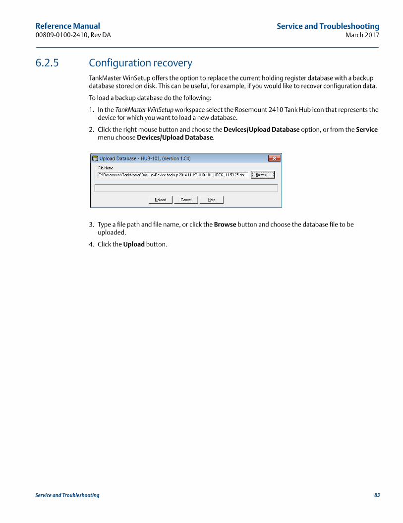
Reference Manual 00809-0100-2410, Rev DA
Service and TroubleshootingMarch 2017
6.2.5 Configuration recoveryTankMaster WinSetup offers the option to replace the current holding register database with a backup database stored on disk. This can be useful, for example, if you would like to recover configuration data.
To load a backup database do the following:
1. In the TankMaster WinSetup workspace select the Rosemount 2410 Tank Hub icon that represents the device for which you want to load a new database.
2. Click the right mouse button and choose the Devices/Upload Database option, or from the Service menu choose Devices/Upload Database.
3. Type a file path and file name, or click the Browse button and choose the database file to be uploaded.
4. Click the Upload button.
83Service and Troubleshooting
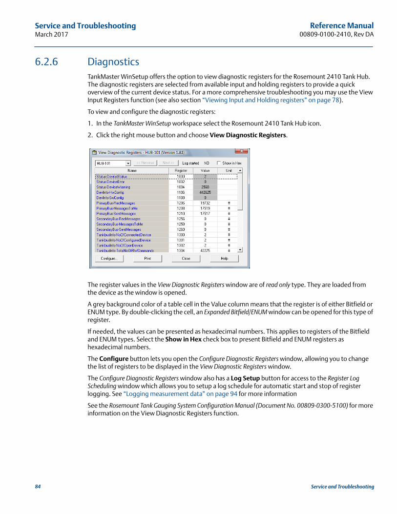
Reference Manual00809-0100-2410, Rev DA
Service and TroubleshootingMarch 2017
6.2.6 DiagnosticsTankMaster WinSetup offers the option to view diagnostic registers for the Rosemount 2410 Tank Hub. The diagnostic registers are selected from available input and holding registers to provide a quick overview of the current device status. For a more comprehensive troubleshooting you may use the View Input Registers function (see also section “Viewing Input and Holding registers” on page 78).
To view and configure the diagnostic registers:
1. In the TankMaster WinSetup workspace select the Rosemount 2410 Tank Hub icon.
2. Click the right mouse button and choose View Diagnostic Registers.
The register values in the View Diagnostic Registers window are of read only type. They are loaded from the device as the window is opened.
A grey background color of a table cell in the Value column means that the register is of either Bitfield or ENUM type. By double-clicking the cell, an Expanded Bitfield/ENUM window can be opened for this type of register.
If needed, the values can be presented as hexadecimal numbers. This applies to registers of the Bitfield and ENUM types. Select the Show in Hex check box to present Bitfield and ENUM registers as hexadecimal numbers.
The Configure button lets you open the Configure Diagnostic Registers window, allowing you to change the list of registers to be displayed in the View Diagnostic Registers window.
The Configure Diagnostic Registers window also has a Log Setup button for access to the Register Log Scheduling window which allows you to setup a log schedule for automatic start and stop of register logging. See “Logging measurement data” on page 94 for more information
See the Rosemount Tank Gauging System Configuration Manual (Document No. 00809-0300-5100) for more information on the View Diagnostic Registers function.
84 Service and Troubleshooting
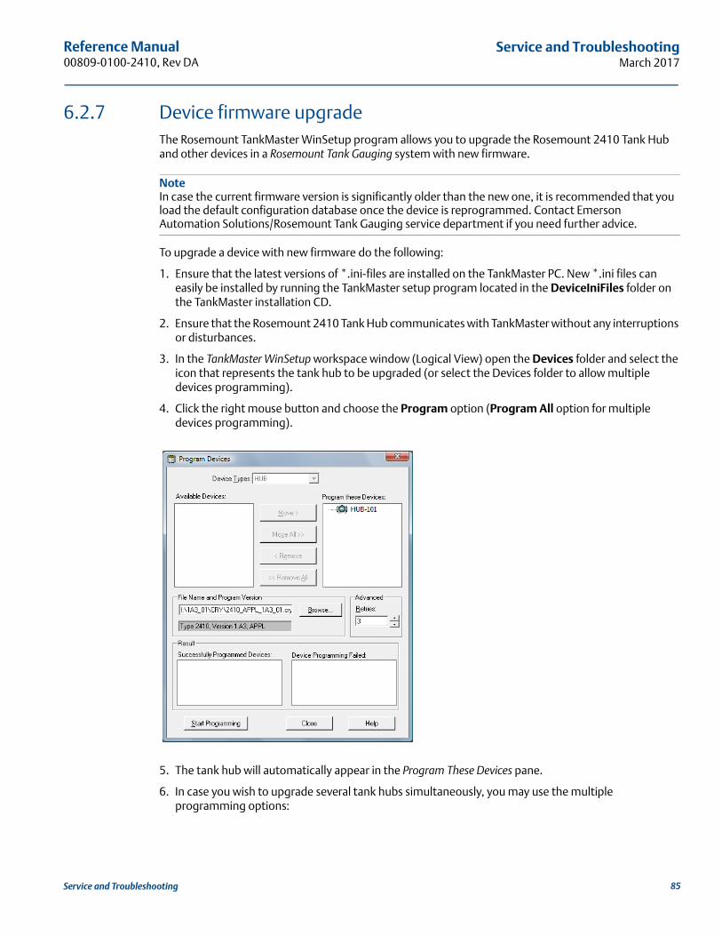
Reference Manual 00809-0100-2410, Rev DA
Service and TroubleshootingMarch 2017
6.2.7 Device firmware upgradeThe Rosemount TankMaster WinSetup program allows you to upgrade the Rosemount 2410 Tank Hub and other devices in a Rosemount Tank Gauging system with new firmware.
NoteIn case the current firmware version is significantly older than the new one, it is recommended that you load the default configuration database once the device is reprogrammed. Contact Emerson Automation Solutions/Rosemount Tank Gauging service department if you need further advice.
To upgrade a device with new firmware do the following:
1. Ensure that the latest versions of *.ini-files are installed on the TankMaster PC. New *.ini files can easily be installed by running the TankMaster setup program located in the DeviceIniFiles folder on the TankMaster installation CD.
2. Ensure that the Rosemount 2410 Tank Hub communicates with TankMaster without any interruptions or disturbances.
3. In the TankMaster WinSetup workspace window (Logical View) open the Devices folder and select the icon that represents the tank hub to be upgraded (or select the Devices folder to allow multiple devices programming).
4. Click the right mouse button and choose the Program option (Program All option for multiple devices programming).
5. The tank hub will automatically appear in the Program These Devices pane.
6. In case you wish to upgrade several tank hubs simultaneously, you may use the multiple programming options:
85Service and Troubleshooting
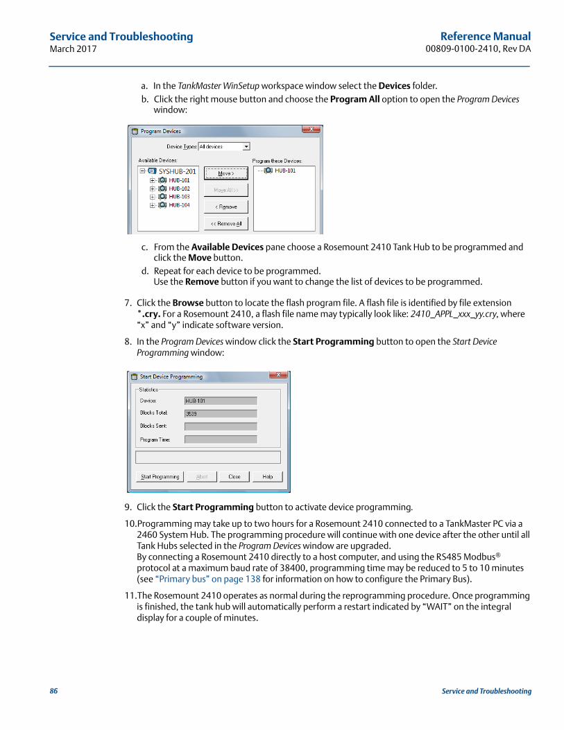
Reference Manual00809-0100-2410, Rev DA
Service and TroubleshootingMarch 2017
a. In the TankMaster WinSetup workspace window select the Devices folder.b. Click the right mouse button and choose the Program All option to open the Program Devices
window:
c. From the Available Devices pane choose a Rosemount 2410 Tank Hub to be programmed and click the Move button.
d. Repeat for each device to be programmed.Use the Remove button if you want to change the list of devices to be programmed.
7. Click the Browse button to locate the flash program file. A flash file is identified by file extension *.cry. For a Rosemount 2410, a flash file name may typically look like: 2410_APPL_xxx_yy.cry, where “x” and “y” indicate software version.
8. In the Program Devices window click the Start Programming button to open the Start Device Programming window:
9. Click the Start Programming button to activate device programming.
10.Programming may take up to two hours for a Rosemount 2410 connected to a TankMaster PC via a 2460 System Hub. The programming procedure will continue with one device after the other until all Tank Hubs selected in the Program Devices window are upgraded.By connecting a Rosemount 2410 directly to a host computer, and using the RS485 Modbus® protocol at a maximum baud rate of 38400, programming time may be reduced to 5 to 10 minutes (see “Primary bus” on page 138 for information on how to configure the Primary Bus).
11.The Rosemount 2410 operates as normal during the reprogramming procedure. Once programming is finished, the tank hub will automatically perform a restart indicated by “WAIT” on the integral display for a couple of minutes.
86 Service and Troubleshooting
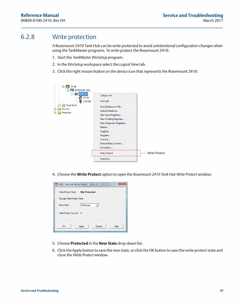
Reference Manual 00809-0100-2410, Rev DA
Service and TroubleshootingMarch 2017
6.2.8 Write protection A Rosemount 2410 Tank Hub can be write protected to avoid unintentional configuration changes when using the TankMaster programs. To write protect the Rosemount 2410:
1. Start the TankMaster WinSetup program.
2. In the WinSetup workspace select the Logical View tab.
3. Click the right mouse button on the device icon that represents the Rosemount 2410:
4. Choose the Write Protect option to open the Rosemount 2410 Tank Hub Write Protect window:
5. Choose Protected in the New State drop-down list.
6. Click the Apply button to save the new state, or click the OK button to save the write protect state and close the Write Protect window.
Write Protect
87Service and Troubleshooting
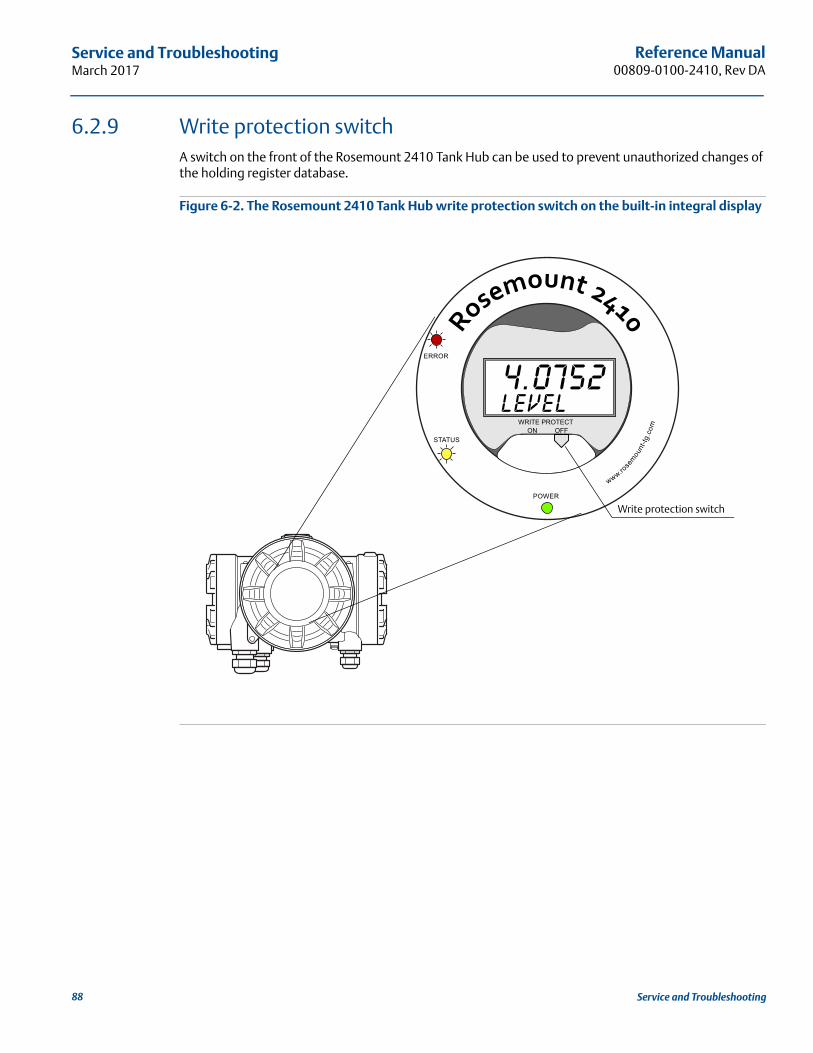
Reference Manual00809-0100-2410, Rev DA
Service and TroubleshootingMarch 2017
6.2.9 Write protection switchA switch on the front of the Rosemount 2410 Tank Hub can be used to prevent unauthorized changes of the holding register database.
Figure 6-2. The Rosemount 2410 Tank Hub write protection switch on the built-in integral display
Write protection switch
88 Service and Troubleshooting
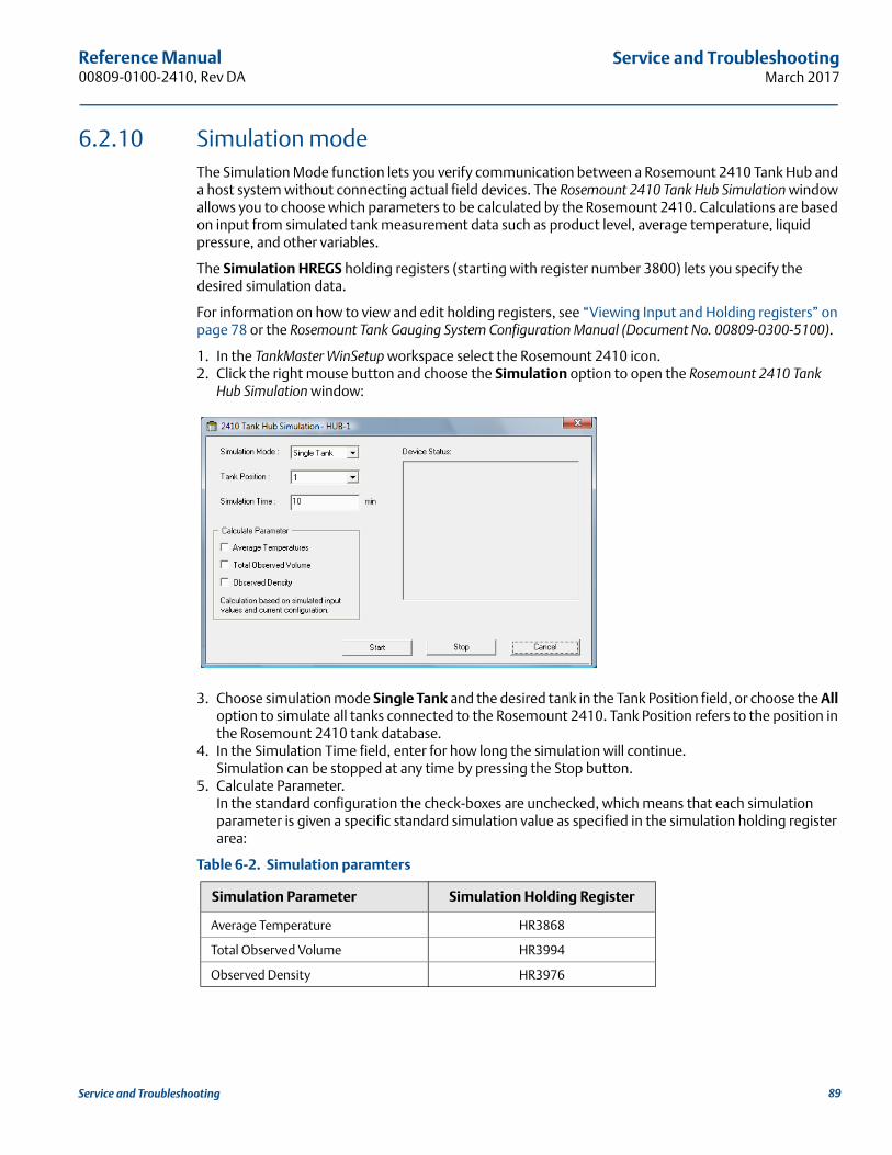
Reference Manual 00809-0100-2410, Rev DA
Service and TroubleshootingMarch 2017
6.2.10 Simulation modeThe Simulation Mode function lets you verify communication between a Rosemount 2410 Tank Hub and a host system without connecting actual field devices. The Rosemount 2410 Tank Hub Simulation window allows you to choose which parameters to be calculated by the Rosemount 2410. Calculations are based on input from simulated tank measurement data such as product level, average temperature, liquid pressure, and other variables.
The Simulation HREGS holding registers (starting with register number 3800) lets you specify the desired simulation data.
For information on how to view and edit holding registers, see “Viewing Input and Holding registers” on page 78 or the Rosemount Tank Gauging System Configuration Manual (Document No. 00809-0300-5100).
1. In the TankMaster WinSetup workspace select the Rosemount 2410 icon.2. Click the right mouse button and choose the Simulation option to open the Rosemount 2410 Tank
Hub Simulation window:
3. Choose simulation mode Single Tank and the desired tank in the Tank Position field, or choose the All option to simulate all tanks connected to the Rosemount 2410. Tank Position refers to the position in the Rosemount 2410 tank database.
4. In the Simulation Time field, enter for how long the simulation will continue.Simulation can be stopped at any time by pressing the Stop button.
5. Calculate Parameter.In the standard configuration the check-boxes are unchecked, which means that each simulation parameter is given a specific standard simulation value as specified in the simulation holding register area:
Table 6-2. Simulation paramters
Simulation Parameter Simulation Holding Register
Average Temperature HR3868
Total Observed Volume HR3994
Observed Density HR3976
89Service and Troubleshooting
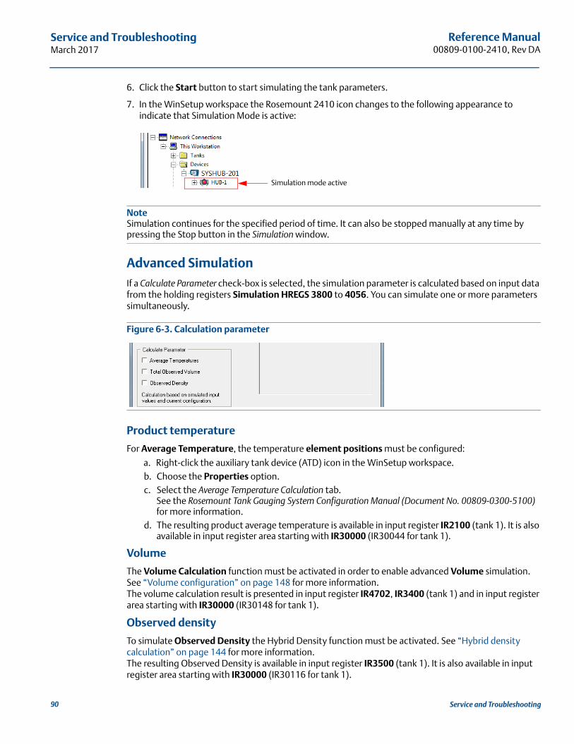
Reference Manual00809-0100-2410, Rev DA
Service and TroubleshootingMarch 2017
6. Click the Start button to start simulating the tank parameters.
7. In the WinSetup workspace the Rosemount 2410 icon changes to the following appearance to indicate that Simulation Mode is active:
NoteSimulation continues for the specified period of time. It can also be stopped manually at any time by pressing the Stop button in the Simulation window.
Advanced SimulationIf a Calculate Parameter check-box is selected, the simulation parameter is calculated based on input data from the holding registers Simulation HREGS 3800 to 4056. You can simulate one or more parameters simultaneously.
Figure 6-3. Calculation parameter
Product temperature
For Average Temperature, the temperature element positions must be configured:
a. Right-click the auxiliary tank device (ATD) icon in the WinSetup workspace.b. Choose the Properties option.c. Select the Average Temperature Calculation tab.
See the Rosemount Tank Gauging System Configuration Manual (Document No. 00809-0300-5100) for more information.
d. The resulting product average temperature is available in input register IR2100 (tank 1). It is also available in input register area starting with IR30000 (IR30044 for tank 1).
Volume
The Volume Calculation function must be activated in order to enable advanced Volume simulation. See “Volume configuration” on page 148 for more information.The volume calculation result is presented in input register IR4702, IR3400 (tank 1) and in input register area starting with IR30000 (IR30148 for tank 1).
Observed density
To simulate Observed Density the Hybrid Density function must be activated. See “Hybrid density calculation” on page 144 for more information.The resulting Observed Density is available in input register IR3500 (tank 1). It is also available in input register area starting with IR30000 (IR30116 for tank 1).
Simulation mode active
90 Service and Troubleshooting
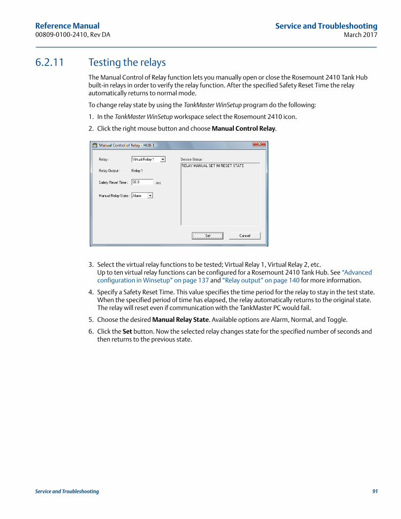
Reference Manual 00809-0100-2410, Rev DA
Service and TroubleshootingMarch 2017
6.2.11 Testing the relaysThe Manual Control of Relay function lets you manually open or close the Rosemount 2410 Tank Hub built-in relays in order to verify the relay function. After the specified Safety Reset Time the relay automatically returns to normal mode.
To change relay state by using the TankMaster WinSetup program do the following:
1. In the TankMaster WinSetup workspace select the Rosemount 2410 icon.
2. Click the right mouse button and choose Manual Control Relay.
3. Select the virtual relay functions to be tested; Virtual Relay 1, Virtual Relay 2, etc. Up to ten virtual relay functions can be configured for a Rosemount 2410 Tank Hub. See “Advanced configuration in Winsetup” on page 137 and “Relay output” on page 140 for more information.
4. Specify a Safety Reset Time. This value specifies the time period for the relay to stay in the test state. When the specified period of time has elapsed, the relay automatically returns to the original state. The relay will reset even if communication with the TankMaster PC would fail.
5. Choose the desired Manual Relay State. Available options are Alarm, Normal, and Toggle.
6. Click the Set button. Now the selected relay changes state for the specified number of seconds and then returns to the previous state.
91Service and Troubleshooting
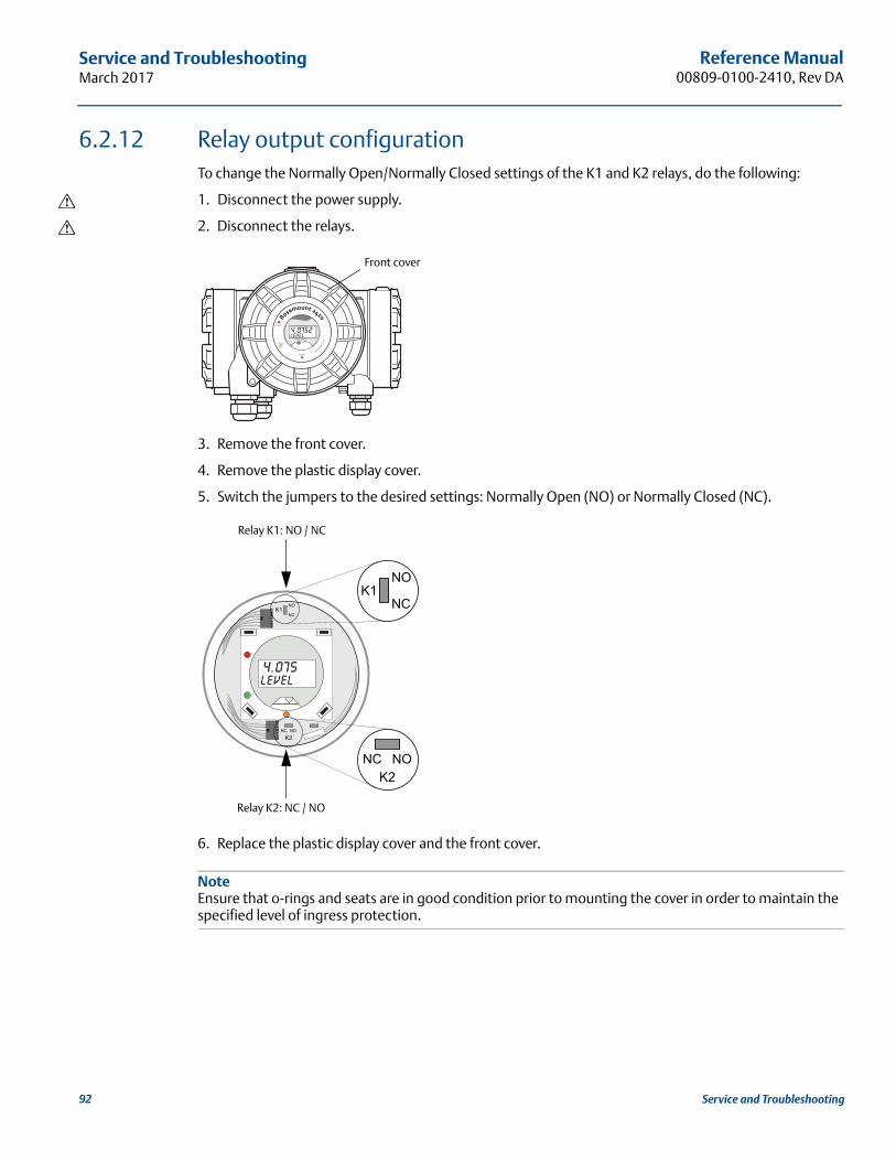
Reference Manual00809-0100-2410, Rev DA
Service and TroubleshootingMarch 2017
6.2.12 Relay output configurationTo change the Normally Open/Normally Closed settings of the K1 and K2 relays, do the following:
1. Disconnect the power supply.
2. Disconnect the relays.
3. Remove the front cover.
4. Remove the plastic display cover.
5. Switch the jumpers to the desired settings: Normally Open (NO) or Normally Closed (NC).
6. Replace the plastic display cover and the front cover.
NoteEnsure that o-rings and seats are in good condition prior to mounting the cover in order to maintain the specified level of ingress protection.
Front cover
Relay K2: NC / NO
Relay K1: NO / NC
92 Service and Troubleshooting
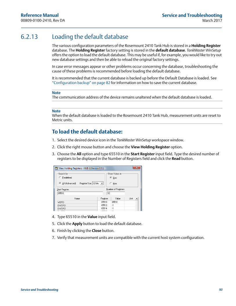
Reference Manual 00809-0100-2410, Rev DA
Service and TroubleshootingMarch 2017
6.2.13 Loading the default databaseThe various configuration parameters of the Rosemount 2410 Tank Hub is stored in a Holding Register database. The Holding Register factory setting is stored in the default database. TankMaster WinSetup offers the option to load the default database. This may be useful if, for example, you would like to try out new database settings and then be able to reload the original factory settings.
In case error messages appear or other problems occur concerning the database, troubleshooting the cause of these problems is recommended before loading the default database.
It is recommended that the current database is backed up before the Default Database is loaded. See “Configuration backup” on page 82 for information on how to save the current database.
NoteThe communication address of the device remains unaltered when the default database is loaded.
NoteWhen the default database is loaded to the Rosemount 2410 Tank Hub, measurement units are reset to Metric units.
To load the default database:1. Select the desired device icon in the TankMaster WinSetup workspace window.
2. Click the right mouse button and choose the View Holding Register option.
3. Choose the All option and type 65510 in the Start Register input field. Type the desired number of registers to be displayed in the Number of Registers field and click the Read button.
4. Type 65510 in the Value input field.
5. Click the Apply button to load the default database.
6. Finish by clicking the Close button.
7. Verify that measurement units are compatible with the current host system configuration.
93Service and Troubleshooting
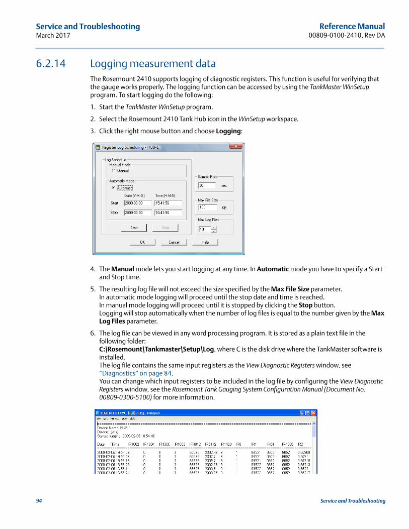
Reference Manual00809-0100-2410, Rev DA
Service and TroubleshootingMarch 2017
6.2.14 Logging measurement dataThe Rosemount 2410 supports logging of diagnostic registers. This function is useful for verifying that the gauge works properly. The logging function can be accessed by using the TankMaster WinSetup program. To start logging do the following:
1. Start the TankMaster WinSetup program.
2. Select the Rosemount 2410 Tank Hub icon in the WinSetup workspace.
3. Click the right mouse button and choose Logging:
4. The Manual mode lets you start logging at any time. In Automatic mode you have to specify a Start and Stop time.
5. The resulting log file will not exceed the size specified by the Max File Size parameter.In automatic mode logging will proceed until the stop date and time is reached.In manual mode logging will proceed until it is stopped by clicking the Stop button.Logging will stop automatically when the number of log files is equal to the number given by the Max Log Files parameter.
6. The log file can be viewed in any word processing program. It is stored as a plain text file in the following folder:C:\Rosemount\Tankmaster\Setup\Log, where C is the disk drive where the TankMaster software is installed. The log file contains the same input registers as the View Diagnostic Registers window, see “Diagnostics” on page 84. You can change which input registers to be included in the log file by configuring the View Diagnostic Registers window, see the Rosemount Tank Gauging System Configuration Manual (Document No. 00809-0300-5100) for more information.
94 Service and Troubleshooting
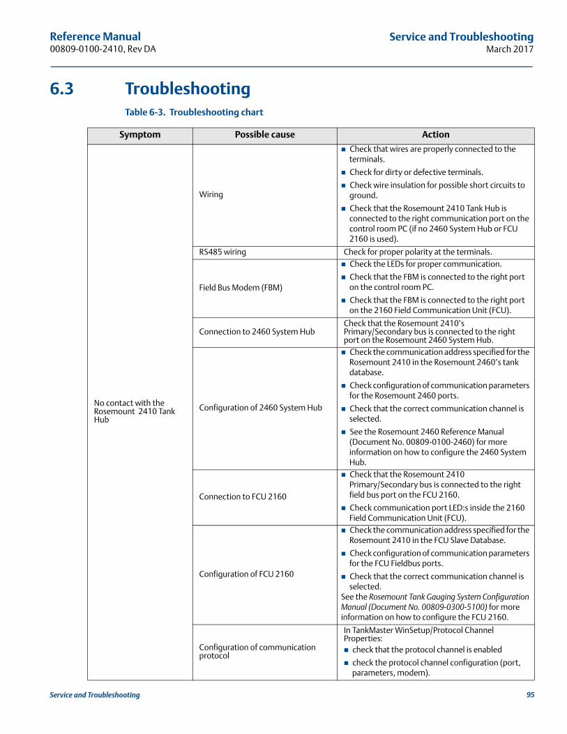
Reference Manual 00809-0100-2410, Rev DA
Service and TroubleshootingMarch 2017
6.3 TroubleshootingTable 6-3. Troubleshooting chart
Symptom Possible cause Action
No contact with the Rosemount 2410 Tank Hub
Wiring
Check that wires are properly connected to the terminals.
Check for dirty or defective terminals.
Check wire insulation for possible short circuits to ground.
Check that the Rosemount 2410 Tank Hub is connected to the right communication port on the control room PC (if no 2460 System Hub or FCU 2160 is used).
RS485 wiring Check for proper polarity at the terminals.
Field Bus Modem (FBM)
Check the LEDs for proper communication.
Check that the FBM is connected to the right port on the control room PC.
Check that the FBM is connected to the right port on the 2160 Field Communication Unit (FCU).
Connection to 2460 System HubCheck that the Rosemount 2410’s Primary/Secondary bus is connected to the right port on the Rosemount 2460 System Hub.
Configuration of 2460 System Hub
Check the communication address specified for the Rosemount 2410 in the Rosemount 2460’s tank database.
Check configuration of communication parameters for the Rosemount 2460 ports.
Check that the correct communication channel is selected.
See the Rosemount 2460 Reference Manual (Document No. 00809-0100-2460) for more information on how to configure the 2460 System Hub.
Connection to FCU 2160
Check that the Rosemount 2410 Primary/Secondary bus is connected to the right field bus port on the FCU 2160.
Check communication port LED:s inside the 2160 Field Communication Unit (FCU).
Configuration of FCU 2160
Check the communication address specified for the Rosemount 2410 in the FCU Slave Database.
Check configuration of communication parameters for the FCU Fieldbus ports.
Check that the correct communication channel is selected.
See the Rosemount Tank Gauging System Configuration Manual (Document No. 00809-0300-5100) for more information on how to configure the FCU 2160.
Configuration of communication protocol
In TankMaster WinSetup/Protocol Channel Properties: check that the protocol channel is enabled
check the protocol channel configuration (port, parameters, modem).
95Service and Troubleshooting
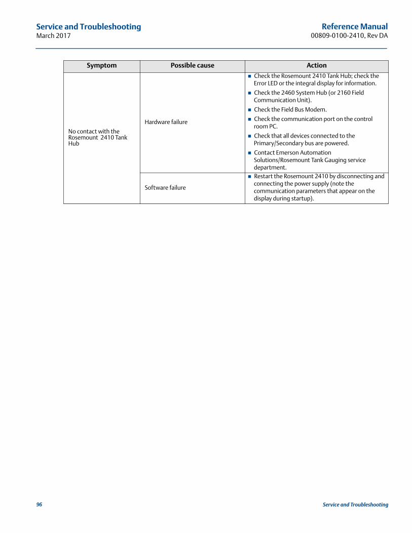
Reference Manual00809-0100-2410, Rev DA
Service and TroubleshootingMarch 2017
No contact with the Rosemount 2410 Tank Hub
Hardware failure
Check the Rosemount 2410 Tank Hub; check the Error LED or the integral display for information.
Check the 2460 System Hub (or 2160 Field Communication Unit).
Check the Field Bus Modem.
Check the communication port on the control room PC.
Check that all devices connected to the Primary/Secondary bus are powered.
Contact Emerson Automation Solutions/Rosemount Tank Gauging service department.
Software failure
Restart the Rosemount 2410 by disconnecting and connecting the power supply (note the communication parameters that appear on the display during startup).
Symptom Possible cause Action
96 Service and Troubleshooting
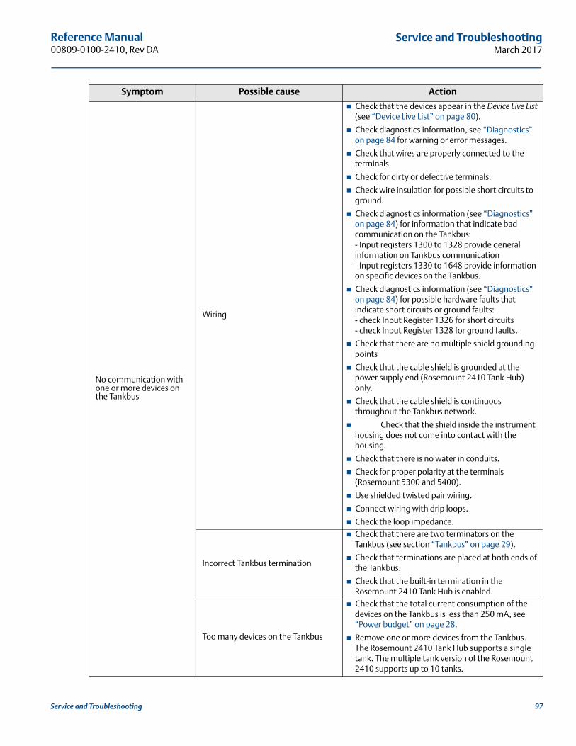
Reference Manual 00809-0100-2410, Rev DA
Service and TroubleshootingMarch 2017
No communication with one or more devices on the Tankbus
Wiring
Check that the devices appear in the Device Live List (see “Device Live List” on page 80).
Check diagnostics information, see “Diagnostics” on page 84 for warning or error messages.
Check that wires are properly connected to the terminals.
Check for dirty or defective terminals.
Check wire insulation for possible short circuits to ground.
Check diagnostics information (see “Diagnostics” on page 84) for information that indicate bad communication on the Tankbus:- Input registers 1300 to 1328 provide general information on Tankbus communication- Input registers 1330 to 1648 provide information on specific devices on the Tankbus.
Check diagnostics information (see “Diagnostics” on page 84) for possible hardware faults that indicate short circuits or ground faults:- check Input Register 1326 for short circuits- check Input Register 1328 for ground faults.
Check that there are no multiple shield grounding points
Check that the cable shield is grounded at the power supply end (Rosemount 2410 Tank Hub) only.
Check that the cable shield is continuous throughout the Tankbus network.
Check that the shield inside the instrument housing does not come into contact with the housing.
Check that there is no water in conduits.
Check for proper polarity at the terminals (Rosemount 5300 and 5400).
Use shielded twisted pair wiring.
Connect wiring with drip loops.
Check the loop impedance.
Incorrect Tankbus termination
Check that there are two terminators on the Tankbus (see section “Tankbus” on page 29).
Check that terminations are placed at both ends of the Tankbus.
Check that the built-in termination in the Rosemount 2410 Tank Hub is enabled.
Too many devices on the Tankbus
Check that the total current consumption of the devices on the Tankbus is less than 250 mA, see “Power budget” on page 28.
Remove one or more devices from the Tankbus. The Rosemount 2410 Tank Hub supports a single tank. The multiple tank version of the Rosemount 2410 supports up to 10 tanks.
Symptom Possible cause Action
97Service and Troubleshooting
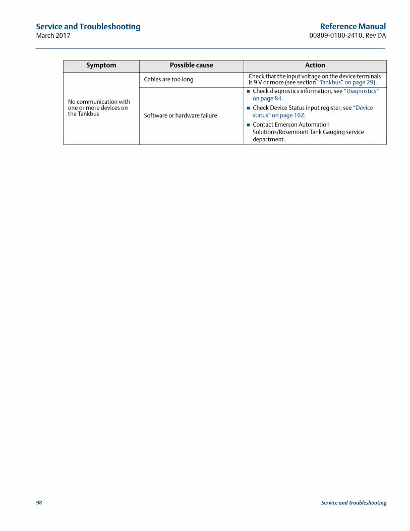
Reference Manual00809-0100-2410, Rev DA
Service and TroubleshootingMarch 2017
No communication with one or more devices on the Tankbus
Cables are too long Check that the input voltage on the device terminals is 9 V or more (see section “Tankbus” on page 29).
Software or hardware failure
Check diagnostics information, see “Diagnostics” on page 84.
Check Device Status input register, see “Device status” on page 102.
Contact Emerson Automation Solutions/Rosemount Tank Gauging service department.
Symptom Possible cause Action
98 Service and Troubleshooting
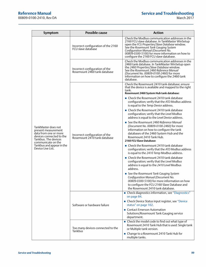
Reference Manual 00809-0100-2410, Rev DA
Service and TroubleshootingMarch 2017
TankMaster does not present measurement data from one or more devices connected to the Tankbus. The devices communicate on the Tankbus and appear in the Device Live List.
Incorrect configuration of the 2160 FCU slave database
Check the Modbus communication addresses in the 2160 FCU slave database. In TankMaster WinSetup open the FCU Properties/Slave Database window.See the Rosemount Tank Gauging System Configuration Manual (Document No. 00809-0300-5100) for more information on how to configure the 2160 FCU slave database.
Incorrect configuration of the Rosemount 2460 tank database
Check the Modbus communication addresses in the 2460 tank database. In TankMaster WinSetup open the 2460 Properties/Slave Database window.See the Rosemount 2460 Reference Manual (Document No. 00809-0100-2460) for more information on how to configure the 2460 tank database.
Incorrect configuration of the Rosemount 2410 tank database
Check the Rosemount 2410 tank database; ensure that the device is available and mapped to the right tank.Rosemount 2460 System Hub tank database:
Check the Rosemount 2410 tank database configuration; verify that the ATD Modbus address is equal to the Temp Device address.
Check the Rosemount 2410 tank database configuration; verify that the Level Modbus address is equal to the Level Device address.
See the Rosemount 2460 Reference Manual (Document No. 00809-0100-2460) for more information on how to configure the tank databases of the 2460 System Hub and the Rosemount 2410 Tank Hub.
2160 FCU Slave Database:
Check the Rosemount 2410 tank database configuration; verify that the ATD Modbus address is equal to the 2410 Temp Modbus address.
Check the Rosemount 2410 tank database configuration; verify that the Level Modbus address is equal to the 2410 Level Modbus address.
See the Rosemount Tank Gauging System Configuration Manual (Document No. 00809-0300-5100) for more information on how to configure the FCU 2160 Slave Database and the Rosemount 2410 tank database.
Software or hardware failure
Check diagnostics information, see “Diagnostics” on page 84.
Check Device Status input register, see “Device status” on page 102.
Contact Emerson Automation Solutions/Rosemount Tank Gauging service department.
Too many devices connected to the Tankbus
Check the model code to find out what type of Rosemount 2410 Tank Hub that is used: Single tank or Multiple tank version.
Change to a Rosemount 2410 Tank Hub for multiple tanks.
Symptom Possible cause Action
99Service and Troubleshooting
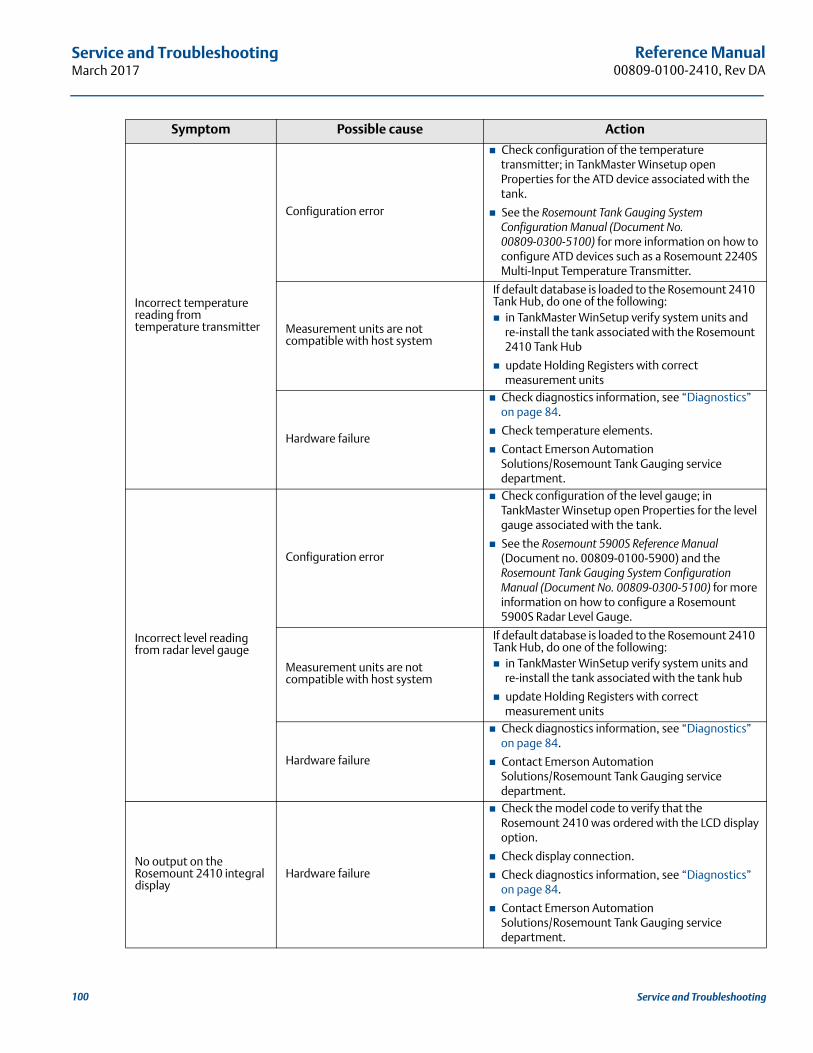
Reference Manual00809-0100-2410, Rev DA
Service and TroubleshootingMarch 2017
Incorrect temperature reading from temperature transmitter
Configuration error
Check configuration of the temperature transmitter; in TankMaster Winsetup open Properties for the ATD device associated with the tank.
See the Rosemount Tank Gauging System Configuration Manual (Document No. 00809-0300-5100) for more information on how to configure ATD devices such as a Rosemount 2240S Multi-Input Temperature Transmitter.
Measurement units are not compatible with host system
If default database is loaded to the Rosemount 2410 Tank Hub, do one of the following: in TankMaster WinSetup verify system units and
re-install the tank associated with the Rosemount 2410 Tank Hub
update Holding Registers with correct measurement units
Hardware failure
Check diagnostics information, see “Diagnostics” on page 84.
Check temperature elements.
Contact Emerson Automation Solutions/Rosemount Tank Gauging service department.
Incorrect level reading from radar level gauge
Configuration error
Check configuration of the level gauge; in TankMaster Winsetup open Properties for the level gauge associated with the tank.
See the Rosemount 5900S Reference Manual (Document no. 00809-0100-5900) and the Rosemount Tank Gauging System Configuration Manual (Document No. 00809-0300-5100) for more information on how to configure a Rosemount 5900S Radar Level Gauge.
Measurement units are not compatible with host system
If default database is loaded to the Rosemount 2410 Tank Hub, do one of the following: in TankMaster WinSetup verify system units and
re-install the tank associated with the tank hub
update Holding Registers with correct measurement units
Hardware failure
Check diagnostics information, see “Diagnostics” on page 84.
Contact Emerson Automation Solutions/Rosemount Tank Gauging service department.
No output on the Rosemount 2410 integral display
Hardware failure
Check the model code to verify that the Rosemount 2410 was ordered with the LCD display option.
Check display connection.
Check diagnostics information, see “Diagnostics” on page 84.
Contact Emerson Automation Solutions/Rosemount Tank Gauging service department.
Symptom Possible cause Action
100 Service and Troubleshooting
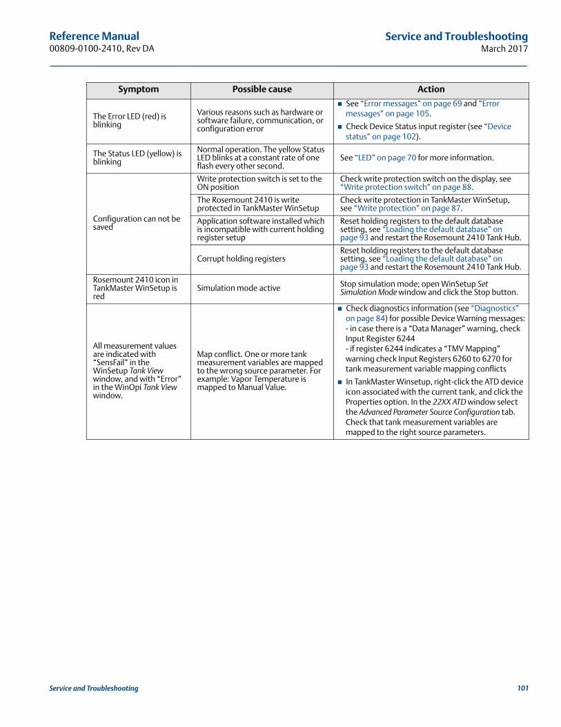
Reference Manual 00809-0100-2410, Rev DA
Service and TroubleshootingMarch 2017
The Error LED (red) is blinking
Various reasons such as hardware or software failure, communication, or configuration error
See “Error messages” on page 69 and “Error messages” on page 105.
Check Device Status input register (see “Device status” on page 102).
The Status LED (yellow) is blinking
Normal operation. The yellow Status LED blinks at a constant rate of one flash every other second.
See “LED” on page 70 for more information.
Configuration can not be saved
Write protection switch is set to the ON position
Check write protection switch on the display, see “Write protection switch” on page 88.
The Rosemount 2410 is write protected in TankMaster WinSetup
Check write protection in TankMaster WinSetup, see “Write protection” on page 87.
Application software installed which is incompatible with current holding register setup
Reset holding registers to the default database setting, see “Loading the default database” on page 93 and restart the Rosemount 2410 Tank Hub.
Corrupt holding registersReset holding registers to the default database setting, see “Loading the default database” on page 93 and restart the Rosemount 2410 Tank Hub.
Rosemount 2410 icon in TankMaster WinSetup is red
Simulation mode active Stop simulation mode; open WinSetup Set Simulation Mode window and click the Stop button.
All measurement values are indicated with “SensFail” in the WinSetup Tank View window, and with “Error” in the WinOpi Tank View window.
Map conflict. One or more tank measurement variables are mapped to the wrong source parameter. For example: Vapor Temperature is mapped to Manual Value.
Check diagnostics information (see “Diagnostics” on page 84) for possible Device Warning messages:- in case there is a “Data Manager” warning, check Input Register 6244- if register 6244 indicates a “TMV Mapping” warning check Input Registers 6260 to 6270 for tank measurement variable mapping conflicts
In TankMaster Winsetup, right-click the ATD device icon associated with the current tank, and click the Properties option. In the 22XX ATD window select the Advanced Parameter Source Configuration tab. Check that tank measurement variables are mapped to the right source parameters.
Symptom Possible cause Action
101Service and Troubleshooting
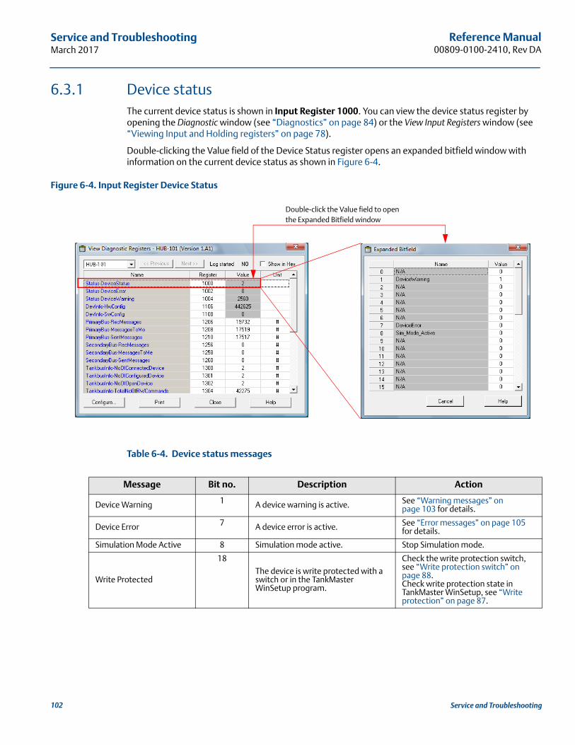
Reference Manual00809-0100-2410, Rev DA
Service and TroubleshootingMarch 2017
6.3.1 Device statusThe current device status is shown in Input Register 1000. You can view the device status register by opening the Diagnostic window (see “Diagnostics” on page 84) or the View Input Registers window (see “Viewing Input and Holding registers” on page 78).
Double-clicking the Value field of the Device Status register opens an expanded bitfield window with information on the current device status as shown in Figure 6-4.
Figure 6-4. Input Register Device Status
Table 6-4. Device status messages
Message Bit no. Description Action
Device Warning 1 A device warning is active. See “Warning messages” on page 103 for details.
Device Error 7 A device error is active. See “Error messages” on page 105 for details.
Simulation Mode Active 8 Simulation mode active. Stop Simulation mode.
Write Protected
18
The device is write protected with a switch or in the TankMaster WinSetup program.
Check the write protection switch, see “Write protection switch” on page 88.Check write protection state in TankMaster WinSetup, see “Write protection” on page 87.
Double-click the Value field to openthe Expanded Bitfield window
102 Service and Troubleshooting
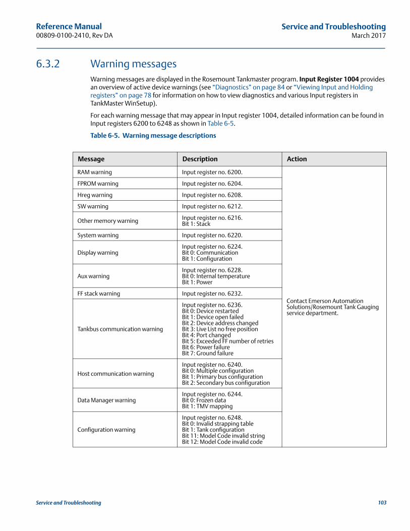
Reference Manual 00809-0100-2410, Rev DA
Service and TroubleshootingMarch 2017
6.3.2 Warning messagesWarning messages are displayed in the Rosemount Tankmaster program. Input Register 1004 provides an overview of active device warnings (see “Diagnostics” on page 84 or “Viewing Input and Holding registers” on page 78 for information on how to view diagnostics and various Input registers in TankMaster WinSetup).
For each warning message that may appear in Input register 1004, detailed information can be found in Input registers 6200 to 6248 as shown in Table 6-5.
Table 6-5. Warning message descriptions
Message Description Action
RAM warning Input register no. 6200.
Contact Emerson Automation Solutions/Rosemount Tank Gauging service department.
FPROM warning Input register no. 6204.
Hreg warning Input register no. 6208.
SW warning Input register no. 6212.
Other memory warning Input register no. 6216.Bit 1: Stack
System warning Input register no. 6220.
Display warningInput register no. 6224.Bit 0: CommunicationBit 1: Configuration
Aux warningInput register no. 6228.Bit 0: Internal temperatureBit 1: Power
FF stack warning Input register no. 6232.
Tankbus communication warning
Input register no. 6236.Bit 0: Device restartedBit 1: Device open failedBit 2: Device address changedBit 3: Live List no free positionBit 4: Port changedBit 5: Exceeded FF number of retriesBit 6: Power failureBit 7: Ground failure
Host communication warning
Input register no. 6240.Bit 0: Multiple configurationBit 1: Primary bus configurationBit 2: Secondary bus configuration
Data Manager warningInput register no. 6244.Bit 0: Frozen dataBit 1: TMV mapping
Configuration warning
Input register no. 6248.Bit 0: Invalid strapping tableBit 1: Tank configurationBit 11: Model Code invalid stringBit 12: Model Code invalid code
103Service and Troubleshooting
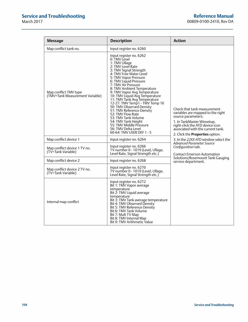
Reference Manual00809-0100-2410, Rev DA
Service and TroubleshootingMarch 2017
Map conflict tank no. Input register no. 6260
Check that tank measurement variables are mapped to the right source parameters:1. In TankMaster Winsetup, right-click the ATD device icon associated with the current tank.2. Click the Properties option.3. In the 22XX ATD window select the Advanced Parameter Source Configuration tab.
Contact Emerson Automation Solutions/Rosemount Tank Gauging service department.
Map conflict TMV type(TMV=Tank Measurement Variable)
Input register no. 62620: TMV Level1: TMV Ullage2: TMV Level Rate3: TMV Signal Strength4: TMV Free Water Level5: TMV Vapor Pressure6: TMV Liquid Pressure7: TMV Air Pressure8: TMV Ambient Temperature9: TMV Vapor Avg Temperature10: TMV Liquid Avg Temperature11: TMV Tank Avg Temperature12-27: TMV Temp1 - TMV Temp 1650: TMV Observed Density51: TMV Reference Density52: TMV Flow Rate53: TMV Tank Volume54: TMV Tank Height55: TMV Middle Pressure56: TMV Delta Level60-64: TMV USER DEF 1 - 5
Map conflict device 1 Input register no. 6264
Map conflict device 1 TV no.(TV=Tank Variable)
Input register no. 6266TV number 0 - 1019 (Level, Ullage, Level Rate, Signal Strength etc.)
Map conflict device 2 Input register no. 6268
Map conflict device 2 TV no.(TV=Tank Variable)
Input register no. 6270TV number 0 - 1019 (Level, Ullage, Level Rate, Signal Strength etc.)
Internal map conflict
Input register no. 6272Bit 1: TMV Vapor average temperatureBit 2: TMV Liquid average temperatureBit 3: TMV Tank average temperatureBit 4: TMV Observed DensityBit 5: TMV Reference DensityBit 6: TMV Tank VolumeBit 7: Mult TV MapBit 8: TMV Internal MapBit 9: TMV Arithmetic Value
Message Description Action
104 Service and Troubleshooting
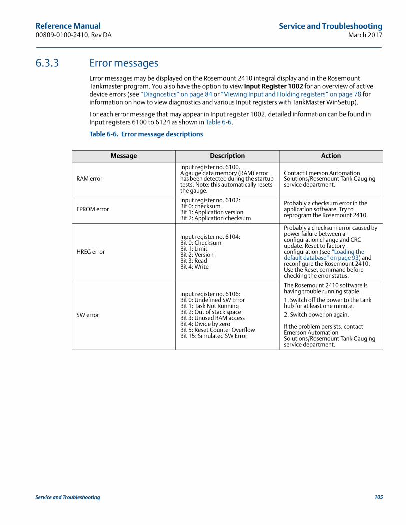
Reference Manual 00809-0100-2410, Rev DA
Service and TroubleshootingMarch 2017
6.3.3 Error messagesError messages may be displayed on the Rosemount 2410 integral display and in the Rosemount Tankmaster program. You also have the option to view Input Register 1002 for an overview of active device errors (see “Diagnostics” on page 84 or “Viewing Input and Holding registers” on page 78 for information on how to view diagnostics and various Input registers with TankMaster WinSetup).
For each error message that may appear in Input register 1002, detailed information can be found in Input registers 6100 to 6124 as shown in Table 6-6.
Table 6-6. Error message descriptions
Message Description Action
RAM error
Input register no. 6100.A gauge data memory (RAM) error has been detected during the startup tests. Note: this automatically resets the gauge.
Contact Emerson Automation Solutions/Rosemount Tank Gauging service department.
FPROM error
Input register no. 6102:Bit 0: checksumBit 1: Application versionBit 2: Application checksum
Probably a checksum error in the application software. Try to reprogram the Rosemount 2410.
HREG error
Input register no. 6104:Bit 0: ChecksumBit 1: LimitBit 2: VersionBit 3: ReadBit 4: Write
Probably a checksum error caused by power failure between a configuration change and CRC update. Reset to factory configuration (see “Loading the default database” on page 93) and reconfigure the Rosemount 2410. Use the Reset command before checking the error status.
SW error
Input register no. 6106:Bit 0: Undefined SW ErrorBit 1: Task Not RunningBit 2: Out of stack spaceBit 3: Unused RAM accessBit 4: Divide by zeroBit 5: Reset Counter OverflowBit 15: Simulated SW Error
The Rosemount 2410 software is having trouble running stable.1. Switch off the power to the tank hub for at least one minute. 2. Switch power on again.
If the problem persists, contact Emerson Automation Solutions/Rosemount Tank Gauging service department.
105Service and Troubleshooting
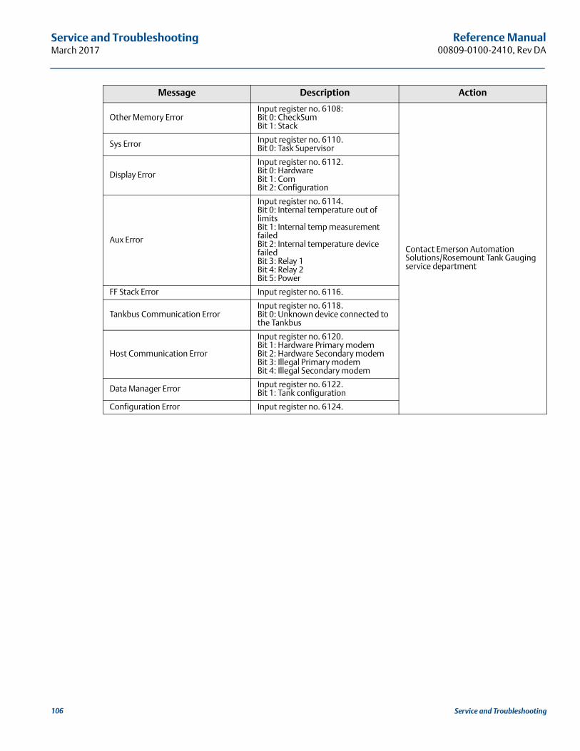
Reference Manual00809-0100-2410, Rev DA
Service and TroubleshootingMarch 2017
Other Memory ErrorInput register no. 6108:Bit 0: CheckSumBit 1: Stack
Contact Emerson Automation Solutions/Rosemount Tank Gauging service department
Sys Error Input register no. 6110.Bit 0: Task Supervisor
Display Error
Input register no. 6112.Bit 0: HardwareBit 1: ComBit 2: Configuration
Aux Error
Input register no. 6114.Bit 0: Internal temperature out of limitsBit 1: Internal temp measurement failedBit 2: Internal temperature device failedBit 3: Relay 1Bit 4: Relay 2Bit 5: Power
FF Stack Error Input register no. 6116.
Tankbus Communication ErrorInput register no. 6118.Bit 0: Unknown device connected to the Tankbus
Host Communication Error
Input register no. 6120.Bit 1: Hardware Primary modemBit 2: Hardware Secondary modemBit 3: Illegal Primary modemBit 4: Illegal Secondary modem
Data Manager Error Input register no. 6122.Bit 1: Tank configuration
Configuration Error Input register no. 6124.
Message Description Action
106 Service and Troubleshooting
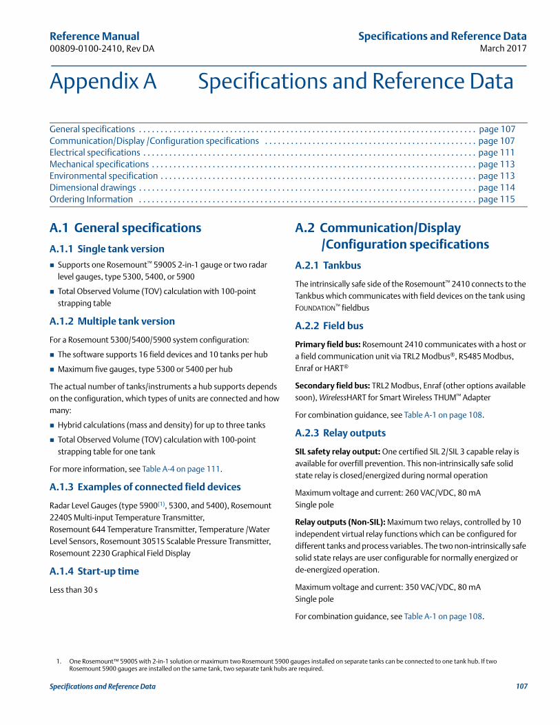
Specifications and Reference DataMarch 2017
Reference Manual 00809-0100-2410, Rev DA
Appendix A Specifications and Reference Data
General specifications . . . . . . . . . . . . . . . . . . . . . . . . . . . . . . . . . . . . . . . . . . . . . . . . . . . . . . . . . . . . . . . . . . . . . . . . . . . . . . page 107Communication/Display /Configuration specifications . . . . . . . . . . . . . . . . . . . . . . . . . . . . . . . . . . . . . . . . . . . . . . . . . page 107Electrical specifications . . . . . . . . . . . . . . . . . . . . . . . . . . . . . . . . . . . . . . . . . . . . . . . . . . . . . . . . . . . . . . . . . . . . . . . . . . . . . page 111Mechanical specifications . . . . . . . . . . . . . . . . . . . . . . . . . . . . . . . . . . . . . . . . . . . . . . . . . . . . . . . . . . . . . . . . . . . . . . . . . . . page 113Environmental specification . . . . . . . . . . . . . . . . . . . . . . . . . . . . . . . . . . . . . . . . . . . . . . . . . . . . . . . . . . . . . . . . . . . . . . . . . page 113Dimensional drawings . . . . . . . . . . . . . . . . . . . . . . . . . . . . . . . . . . . . . . . . . . . . . . . . . . . . . . . . . . . . . . . . . . . . . . . . . . . . . . page 114Ordering Information . . . . . . . . . . . . . . . . . . . . . . . . . . . . . . . . . . . . . . . . . . . . . . . . . . . . . . . . . . . . . . . . . . . . . . . . . . . . . . page 115
A.1 General specifications
A.1.1 Single tank version
Supports one Rosemount™ 5900S 2-in-1 gauge or two radar level gauges, type 5300, 5400, or 5900
Total Observed Volume (TOV) calculation with 100-point strapping table
A.1.2 Multiple tank version
For a Rosemount 5300/5400/5900 system configuration:
The software supports 16 field devices and 10 tanks per hub
Maximum five gauges, type 5300 or 5400 per hub
The actual number of tanks/instruments a hub supports depends on the configuration, which types of units are connected and how many:
Hybrid calculations (mass and density) for up to three tanks
Total Observed Volume (TOV) calculation with 100-point strapping table for one tank
For more information, see Table A-4 on page 111.
A.1.3 Examples of connected field devices
Radar Level Gauges (type 5900(1), 5300, and 5400), Rosemount 2240S Multi-input Temperature Transmitter, Rosemount 644 Temperature Transmitter, Temperature /Water Level Sensors, Rosemount 3051S Scalable Pressure Transmitter, Rosemount 2230 Graphical Field Display
A.1.4 Start-up time
Less than 30 s
A.2 Communication/Display /Configuration specifications
A.2.1 Tankbus
The intrinsically safe side of the Rosemount™ 2410 connects to the Tankbus which communicates with field devices on the tank using FOUNDATION™ fieldbus
A.2.2 Field bus
Primary field bus: Rosemount 2410 communicates with a host or a field communication unit via TRL2 Modbus®, RS485 Modbus, Enraf or HART®
Secondary field bus: TRL2 Modbus, Enraf (other options available soon), WirelessHART for Smart Wireless THUM™ Adapter
For combination guidance, see Table A-1 on page 108.
A.2.3 Relay outputs
SIL safety relay output: One certified SIL 2/SIL 3 capable relay is available for overfill prevention. This non-intrinsically safe solid state relay is closed/energized during normal operation
Maximum voltage and current: 260 VAC/VDC, 80 mASingle pole
Relay outputs (Non-SIL): Maximum two relays, controlled by 10 independent virtual relay functions which can be configured for different tanks and process variables. The two non-intrinsically safe solid state relays are user configurable for normally energized or de-energized operation.
Maximum voltage and current: 350 VAC/VDC, 80 mASingle pole
For combination guidance, see Table A-1 on page 108.
1. One Rosemount™ 5900S with 2-in-1 solution or maximum two Rosemount 5900 gauges installed on separate tanks can be connected to one tank hub. If two Rosemount 5900 gauges are installed on the same tank, two separate tank hubs are required.
107Specifications and Reference Data
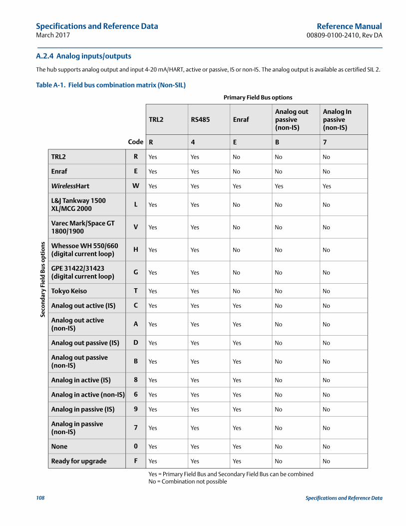
Specifications and Reference DataMarch 2017
Reference Manual00809-0100-2410, Rev DA
A.2.4 Analog inputs/outputs
The hub supports analog output and input 4-20 mA/HART, active or passive, IS or non-IS. The analog output is available as certified SIL 2.
Table A-1. Field bus combination matrix (Non-SIL)
Seco
nd
ary
Fiel
d B
us
opt
ions
Primary Field Bus options
TRL2 RS485 EnrafAnalog out passive (non-IS)
Analog In passive (non-IS)
Code R 4 E B 7
TRL2 R Yes Yes No No No
Enraf E Yes Yes No No No
WirelessHart W Yes Yes Yes Yes Yes
L&J Tankway 1500 XL/MCG 2000
L Yes Yes No No No
Varec Mark/Space GT 1800/1900
V Yes Yes No No No
Whessoe WH 550/660 (digital current loop)
H Yes Yes No No No
GPE 31422/31423 (digital current loop)
G Yes Yes No No No
Tokyo Keiso T Yes Yes No No No
Analog out active (IS) C Yes Yes Yes No No
Analog out active (non-IS)
A Yes Yes Yes No No
Analog out passive (IS) D Yes Yes Yes No No
Analog out passive (non-IS)
B Yes Yes Yes No No
Analog in active (IS) 8 Yes Yes Yes No No
Analog in active (non-IS) 6 Yes Yes Yes No No
Analog in passive (IS) 9 Yes Yes Yes No No
Analog in passive (non-IS)
7 Yes Yes Yes No No
None 0 Yes Yes Yes No No
Ready for upgrade F Yes Yes Yes No No
Yes = Primary Field Bus and Secondary Field Bus can be combinedNo = Combination not possible
108 Specifications and Reference Data
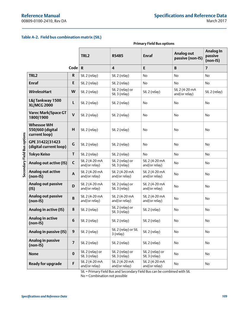
Specifications and Reference DataMarch 2017
Reference Manual 00809-0100-2410, Rev DA
Table A-2. Field bus combination matrix (SIL)
Seco
nd
ary
Fiel
d B
us
opt
ion
s
Primary Field Bus options
TRL2 RS485 EnrafAnalog out passive (non-IS)
Analog In passive (non-IS)
Code R 4 E B 7
TRL2 R SIL 2 (relay) SIL 2 (relay) No No No
Enraf E SIL 2 (relay) SIL 2 (relay) No No No
WirelessHart W SIL 2 (relay)SIL 2 (relay) or SIL 3 (relay)
SIL 2 (relay)SIL 2 (4-20 mA and/or relay)
SIL 2 (relay)
L&J Tankway 1500 XL/MCG 2000
L SIL 2 (relay) SIL 2 (relay) No No No
Varec Mark/Space GT 1800/1900
V SIL 2 (relay) SIL 2 (relay) No No No
Whessoe WH 550/660 (digital current loop)
H SIL 2 (relay) SIL 2 (relay) No No No
GPE 31422/31423 (digital current loop)
G SIL 2 (relay) SIL 2 (relay) No No No
Tokyo Keiso T SIL 2 (relay) SIL 2 (relay) No No No
Analog out active (IS) C SIL 2 (4-20 mA and/or relay)
SIL 2 (relay) or SIL 3 (relay)
SIL 2 (4-20 mA and/or relay)
No No
Analog out active (non-IS)
A SIL 2 (4-20 mA and/or relay)
SIL 2 (4-20 mA and/or relay)
SIL 2 (4-20 mA and/or relay)
No No
Analog out passive (IS)
D SIL 2 (4-20 mA and/or relay)
SIL 2 (relay) or SIL 3 (relay)
SIL 2 (4-20 mA and/or relay)
No No
Analog out passive (non-IS)
B SIL 2 (4-20 mA and/or relay)
SIL 2 (4-20 mA and/or relay)
SIL 2 (4-20 mA and/or relay)
No No
Analog in active (IS) 8 SIL 2 (relay)SIL 2 (relay) or SIL 3 (relay)
SIL 2 (relay) No No
Analog in active (non-IS)
6 SIL 2 (relay) SIL 2 (relay) SIL 2 (relay) No No
Analog in passive (IS) 9 SIL 2 (relay)SIL 2 (relay) or SIL 3 (relay)
SIL 2 (relay) No No
Analog in passive (non-IS)
7 SIL 2 (relay) SIL 2 (relay) SIL 2 (relay) No No
None 0 SIL 2 (relay) or SIL 3 (relay)
SIL 2 (relay) or SIL 3 (relay)
SIL 2 (relay) or SIL 3 (relay)
No No
Ready for upgrade F SIL 2 (4-20 mA and/or relay)
SIL 2 (4-20 mAand/or relay)
SIL 2 (4-20 mAand/or relay)
No No
SIL = Primary Field Bus and Secondary Field Bus can be combined with SILNo = Combination not possible
109Specifications and Reference Data
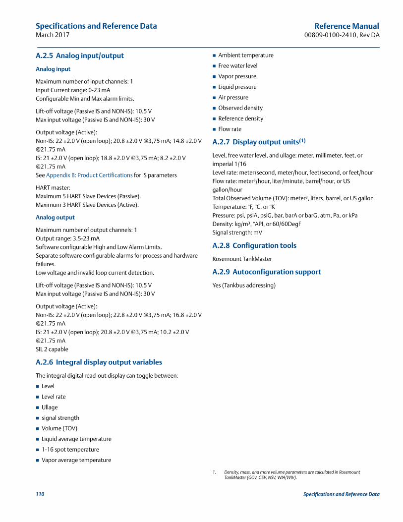
Specifications and Reference DataMarch 2017
Reference Manual00809-0100-2410, Rev DA
A.2.5 Analog input/output
Analog input
Maximum number of input channels: 1Input Current range: 0-23 mAConfigurable Min and Max alarm limits.
Lift-off voltage (Passive IS and NON-IS): 10.5 VMax input voltage (Passive IS and NON-IS): 30 V
Output voltage (Active):Non-IS: 22 ±2.0 V (open loop); 20.8 ±2.0 V @3,75 mA; 14.8 ±2.0 V @21.75 mAIS: 21 ±2.0 V (open loop); 18.8 ±2.0 V @3,75 mA; 8.2 ±2.0 V @21.75 mASee Appendix B: Product Certifications for IS parameters
HART master:Maximum 5 HART Slave Devices (Passive).Maximum 3 HART Slave Devices (Active).
Analog output
Maximum number of output channels: 1Output range: 3.5-23 mASoftware configurable High and Low Alarm Limits.Separate software configurable alarms for process and hardware failures.Low voltage and invalid loop current detection.
Lift-off voltage (Passive IS and NON-IS): 10.5 VMax input voltage (Passive IS and NON-IS): 30 V
Output voltage (Active):Non-IS: 22 ±2.0 V (open loop); 22.8 ±2.0 V @3,75 mA; 16.8 ±2.0 V @21.75 mAIS: 21 ±2.0 V (open loop); 20.8 ±2.0 V @3,75 mA; 10.2 ±2.0 V @21.75 mASIL 2 capable
A.2.6 Integral display output variables
The integral digital read-out display can toggle between:
Level
Level rate
Ullage
signal strength
Volume (TOV)
Liquid average temperature
1-16 spot temperature
Vapor average temperature
Ambient temperature
Free water level
Vapor pressure
Liquid pressure
Air pressure
Observed density
Reference density
Flow rate
A.2.7 Display output units(1)
Level, free water level, and ullage: meter, millimeter, feet, or imperial 1/16Level rate: meter/second, meter/hour, feet/second, or feet/hourFlow rate: meter³/hour, liter/minute, barrel/hour, or US gallon/hourTotal Observed Volume (TOV): meter³, liters, barrel, or US gallonTemperature: °F, °C, or °KPressure: psi, psiA, psiG, bar, barA or barG, atm, Pa, or kPaDensity: kg/m³, °API, or 60/60DegFSignal strength: mV
A.2.8 Configuration tools
Rosemount TankMaster
A.2.9 Autoconfiguration support
Yes (Tankbus addressing)
1. Density, mass, and more volume parameters are calculated in Rosemount TankMaster (GOV, GSV, NSV, WIA/WIV).
110 Specifications and Reference Data
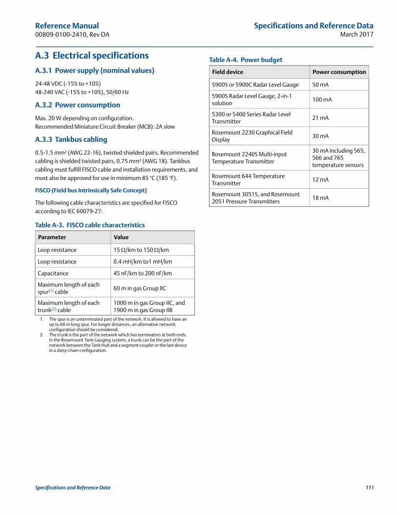
Specifications and Reference DataMarch 2017
Reference Manual 00809-0100-2410, Rev DA
A.3 Electrical specifications
A.3.1 Power supply (nominal values)
24-48 VDC (-15% to +10%)48-240 VAC (-15% to +10%), 50/60 Hz
A.3.2 Power consumption
Max. 20 W depending on configuration. Recommended Miniature Circuit Breaker (MCB): 2A slow
A.3.3 Tankbus cabling
0.5-1.5 mm² (AWG 22-16), twisted shielded pairs. Recommended cabling is shielded twisted pairs, 0.75 mm² (AWG 18). Tankbus cabling must fulfill FISCO cable and installation requirements, and must also be approved for use in minimum 85 °C (185 °F).
FISCO (Field bus Intrinsically Safe Concept)
The following cable characteristics are specified for FISCO according to IEC 60079-27:
Table A-3. FISCO cable characteristics
Parameter Value
Loop resistance 15 /km to 150 /km
Loop resistance 0.4 mH/km to1 mH/km
Capacitance 45 nF/km to 200 nF/km
Maximum length of each spur(1) cable
1. The spur is an unterminated part of the network. It is allowed to have an up to 60 m long spur. For longer distances, an alternative network configuration should be considered.
60 m in gas Group IIC
Maximum length of each trunk(2) cable
2. The trunk is the part of the network which has terminators at both ends. In the Rosemount Tank Gauging system, a trunk can be the part of the network between the Tank Hub and a segment coupler or the last device in a daisy-chain configuration.
1000 m in gas Group IIC, and 1900 m in gas Group IIB
Table A-4. Power budget
Field device Power consumption
5900S or 5900C Radar Level Gauge 50 mA
5900S Radar Level Gauge, 2-in-1 solution
100 mA
5300 or 5400 Series Radar Level Transmitter
21 mA
Rosemount 2230 Graphical Field Display
30 mA
Rosemount 2240S Multi-input Temperature Transmitter
30 mA including 565, 566 and 765 temperature sensors
Rosemount 644 Temperature Transmitter
12 mA
Rosemount 3051S, and Rosemount 2051 Pressure Transmitters
18 mA
111Specifications and Reference Data
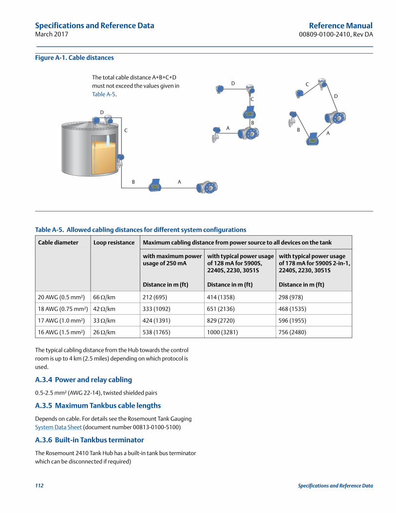
Specifications and Reference DataMarch 2017
Reference Manual00809-0100-2410, Rev DA
Figure A-1. Cable distances
The typical cabling distance from the Hub towards the control room is up to 4 km (2.5 miles) depending on which protocol is used.
A.3.4 Power and relay cabling
0.5-2.5 mm² (AWG 22-14), twisted shielded pairs
A.3.5 Maximum Tankbus cable lengths
Depends on cable. For details see the Rosemount Tank Gauging System Data Sheet (document number 00813-0100-5100)
A.3.6 Built-in Tankbus terminator
The Rosemount 2410 Tank Hub has a built-in tank bus terminator which can be disconnected if required)
D
C
B A
D
D
C
C
BB
AA
The total cable distance A+B+C+D must not exceed the values given in Table A-5.
Table A-5. Allowed cabling distances for different system configurations
Cable diameter Loop resistance Maximum cabling distance from power source to all devices on the tank
with maximum power usage of 250 mA
Distance in m (ft)
with typical power usage of 128 mA for 5900S, 2240S, 2230, 3051S
Distance in m (ft)
with typical power usage of 178 mA for 5900S 2-in-1, 2240S, 2230, 3051S
Distance in m (ft)
20 AWG (0.5 mm²) 66 /km 212 (695) 414 (1358) 298 (978)
18 AWG (0.75 mm²) 42 /km 333 (1092) 651 (2136) 468 (1535)
17 AWG (1.0 mm²) 33 /km 424 (1391) 829 (2720) 596 (1955)
16 AWG (1.5 mm²) 26 /km 538 (1765) 1000 (3281) 756 (2480)
112 Specifications and Reference Data
Specifications and Reference DataMarch 2017
Reference Manual 00809-0100-2410, Rev DA
A.4 Mechanical specifications
A.4.1 Housing material
Polyurethane-covered die-cast aluminum
A.4.2 Cable entry (connection/glands)
Non-IS side: Two ½ - 14 NPT and Two ¾ - 14 NPT entries for cable glands or conduits
IS side: Two ½ - 14 NPT entries for cable glands or conduits
Three metal plugs to seal any unused ports are included in the delivery
Optional:
M20 x 1.5 and M25 x 1.5 conduit / cable adapter
Cable glands in metal (½ - 14 NPT and ¾ - 14 NPT)
4-pin male Eurofast connector or A size Mini 4-pin male Minifast connector
A.4.3 Installation
Can be installed on a 33.4-60.3 mm (1-2 in.) diameter pipe or wall, at ground level close to the tank or on top of the tank using existing cabling.
A.4.4 Weight
4.7 kg (10.4 lbs)
A.5 Environmental specification
A.5.1 Ambient temperature
-40 to 70 °C (-40 to 158 °F). Minimum start-up temperature is -50 °C (-58 °F).With LCD display: -25 to 70 °C (-13 to 158 °F)
A.5.2 Storage temperature
-50 to 85 °C (-58 to 185 °F)With LCD display: -40 to 85 °C (-40 to 185 °F)
A.5.3 Humidity
0 - 100% relative humidity
A.5.4 Ingress protection
IP 66 and IP 67 (Nema 4X)
A.5.5 Metrology sealing possibility
Yes
A.5.6 Write protect switch
Yes (hardware and software write protection)
A.5.7 Transient / built-in lightning protection
According to IEC 61000-4-5, level 4 kV line to ground. Complies with IEEE 587 Category B transient protection and IEEE 472 surge protection
113Specifications and Reference Data
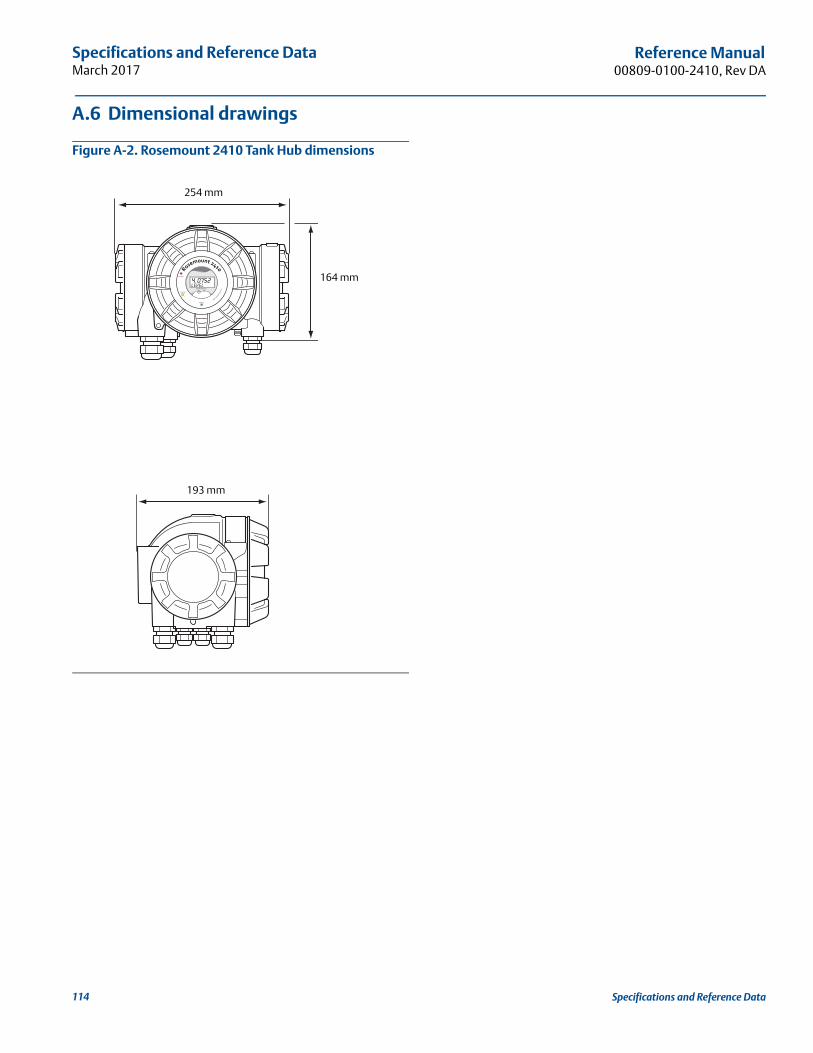
Specifications and Reference DataMarch 2017
Reference Manual00809-0100-2410, Rev DA
A.6 Dimensional drawings
Figure A-2. Rosemount 2410 Tank Hub dimensions
254 mm
193 mm
164 mm
114 Specifications and Reference Data
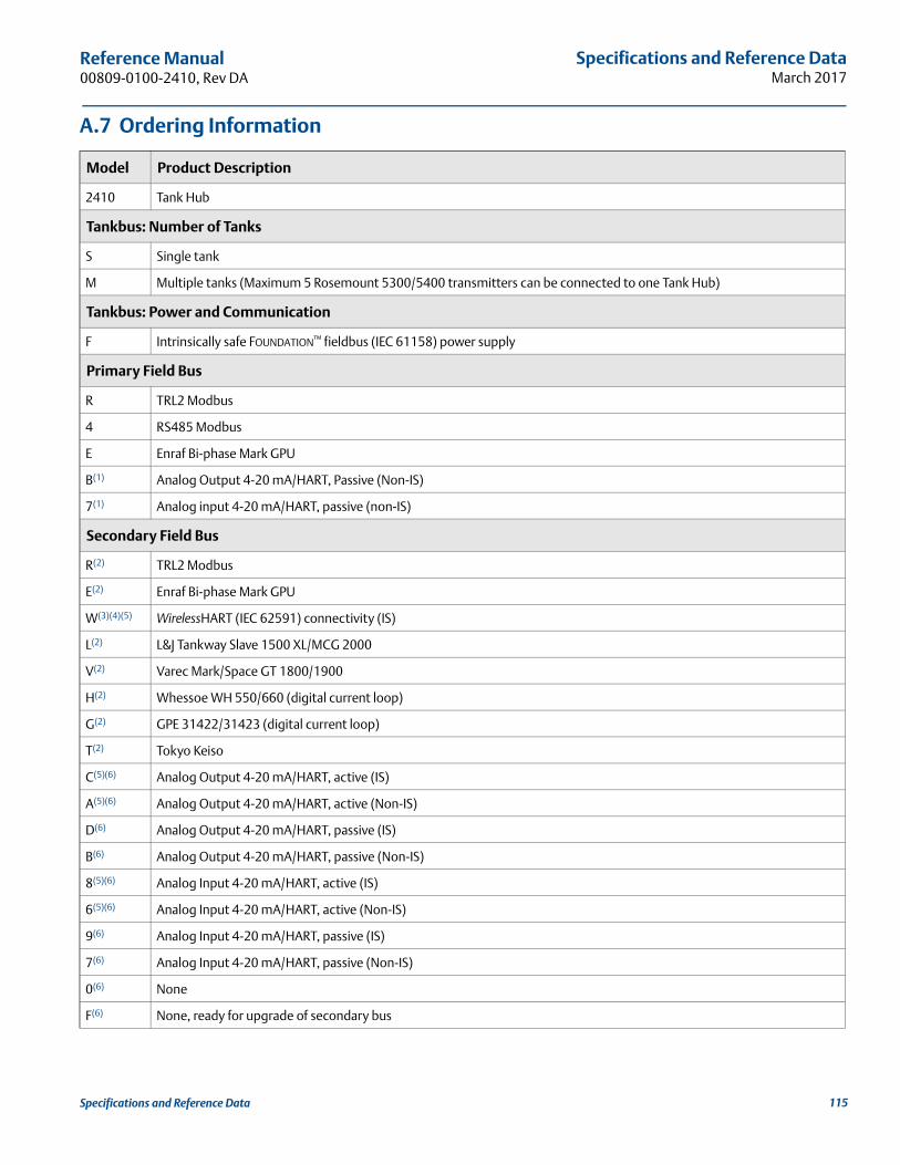
Specifications and Reference DataMarch 2017
Reference Manual 00809-0100-2410, Rev DA
A.7 Ordering Information
Model Product Description
2410 Tank Hub
Tankbus: Number of Tanks
S Single tank
M Multiple tanks (Maximum 5 Rosemount 5300/5400 transmitters can be connected to one Tank Hub)
Tankbus: Power and Communication
F Intrinsically safe FOUNDATION™ fieldbus (IEC 61158) power supply
Primary Field Bus
R TRL2 Modbus
4 RS485 Modbus
E Enraf Bi-phase Mark GPU
B(1) Analog Output 4-20 mA/HART, Passive (Non-IS)
7(1) Analog input 4-20 mA/HART, passive (non-IS)
Secondary Field Bus
R(2) TRL2 Modbus
E(2) Enraf Bi-phase Mark GPU
W(3)(4)(5) WirelessHART (IEC 62591) connectivity (IS)
L(2) L&J Tankway Slave 1500 XL/MCG 2000
V(2) Varec Mark/Space GT 1800/1900
H(2) Whessoe WH 550/660 (digital current loop)
G(2) GPE 31422/31423 (digital current loop)
T(2) Tokyo Keiso
C(5)(6) Analog Output 4-20 mA/HART, active (IS)
A(5)(6) Analog Output 4-20 mA/HART, active (Non-IS)
D(6) Analog Output 4-20 mA/HART, passive (IS)
B(6) Analog Output 4-20 mA/HART, passive (Non-IS)
8(5)(6) Analog Input 4-20 mA/HART, active (IS)
6(5)(6) Analog Input 4-20 mA/HART, active (Non-IS)
9(6) Analog Input 4-20 mA/HART, passive (IS)
7(6) Analog Input 4-20 mA/HART, passive (Non-IS)
0(6) None
F(6) None, ready for upgrade of secondary bus
115Specifications and Reference Data
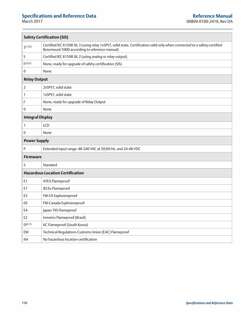
Specifications and Reference DataMarch 2017
Reference Manual00809-0100-2410, Rev DA
Safety Certification (SIS)
3(7)(8) Certified IEC 61508 SIL 3 (using relay 1xSPST, solid state. Certification valid only when connected to a safety-certified Rosemount 5900 according to reference manual)
S Certified IEC 61508 SIL 2 (using analog or relay output)
F(8)(9) None, ready for upgrade of safety certification (SIS)
0 None
Relay Output
2 2xSPST, solid state
1 1xSPST, solid state
F None, ready for upgrade of Relay Output
0 None
Integral Display
1 LCD
0 None
Power Supply
P Extended input range: 48-240 VAC at 50/60 Hz, and 24-48 VDC
Firmware
S Standard
Hazardous Location Certification
E1 ATEX Flameproof
E7 IECEx Flameproof
E5 FM-US Explosionproof
E6 FM-Canada Explosionproof
E4 Japan TIIS Flameproof
E2 Inmetro Flameproof (Brazil)
EP(10) KC Flameproof (South Korea)
EM Technical Regulations Customs Union (EAC) Flameproof
NA No hazardous location certification
116 Specifications and Reference Data
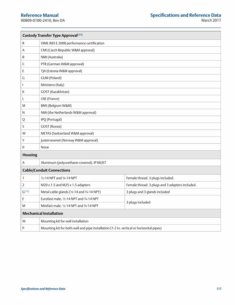
Specifications and Reference DataMarch 2017
Reference Manual 00809-0100-2410, Rev DA
Custody Transfer Type Approval(11)
R OIML R85 E 2008 performance certification
A CMI (Czech Republic W&M approval)
B NMI (Australia)
C PTB (German W&M approval)
E TJA (Estonia W&M approval)
G GUM (Poland)
I Ministero (Italy)
K GOST (Kazakhstan)
L LNE (France)
M BMS (Belgium W&M)
N NMi (the Netherlands W&M approval)
Q IPQ (Portugal)
S GOST (Russia)
W METAS (Switzerland W&M approval)
Y Justervesenet (Norway W&M approval)
0 None
Housing
A Aluminum (polyurethane-covered). IP 66/67
Cable/Conduit Connections
1 ½-14 NPT and ¾-14 NPT Female thread. 3 plugs included.
2 M20 x 1.5 and M25 x 1.5 adapters Female thread. 3 plugs and 3 adapters included.
G(12) Metal cable glands (½-14 and ¾-14 NPT) 3 plugs and 3 glands included
E Eurofast male, ½-14 NPT and ¾-14 NPT3 plugs included
M Minifast male, ½-14 NPT and ¾-14 NPT
Mechanical Installation
W Mounting kit for wall installation
P Mounting kit for both wall and pipe installation (1-2 in. vertical or horizontal pipes)
117Specifications and Reference Data
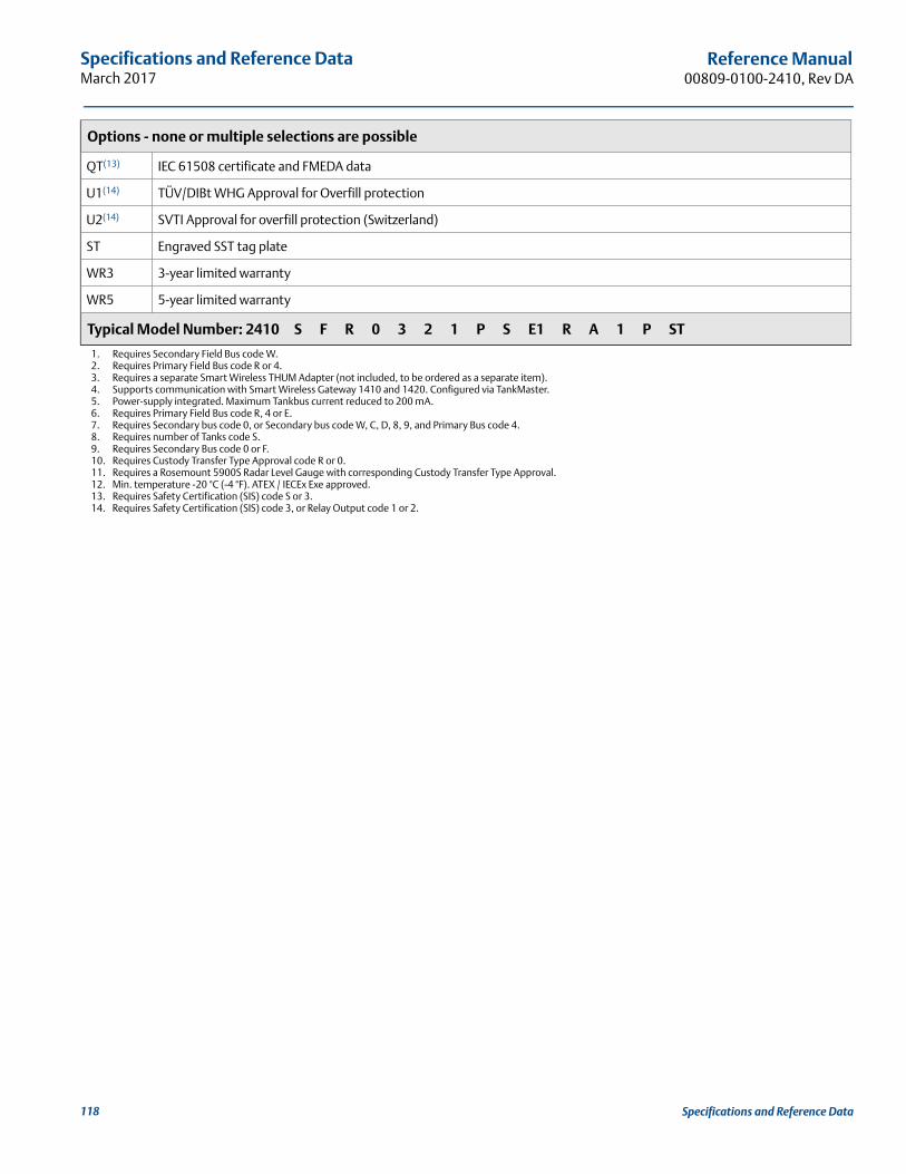
Specifications and Reference DataMarch 2017
Reference Manual00809-0100-2410, Rev DA
Options - none or multiple selections are possible
QT(13) IEC 61508 certificate and FMEDA data
U1(14) TÜV/DIBt WHG Approval for Overfill protection
U2(14) SVTI Approval for overfill protection (Switzerland)
ST Engraved SST tag plate
WR3 3-year limited warranty
WR5 5-year limited warranty
Typical Model Number: 2410 S F R 0 3 2 1 P S E1 R A 1 P ST
1. Requires Secondary Field Bus code W.2. Requires Primary Field Bus code R or 4.3. Requires a separate Smart Wireless THUM Adapter (not included, to be ordered as a separate item).4. Supports communication with Smart Wireless Gateway 1410 and 1420. Configured via TankMaster.5. Power-supply integrated. Maximum Tankbus current reduced to 200 mA.6. Requires Primary Field Bus code R, 4 or E. 7. Requires Secondary bus code 0, or Secondary bus code W, C, D, 8, 9, and Primary Bus code 4.8. Requires number of Tanks code S.9. Requires Secondary Bus code 0 or F.10. Requires Custody Transfer Type Approval code R or 0.11. Requires a Rosemount 5900S Radar Level Gauge with corresponding Custody Transfer Type Approval.12. Min. temperature -20 °C (-4 °F). ATEX / IECEx Exe approved.13. Requires Safety Certification (SIS) code S or 3.14. Requires Safety Certification (SIS) code 3, or Relay Output code 1 or 2.
118 Specifications and Reference Data
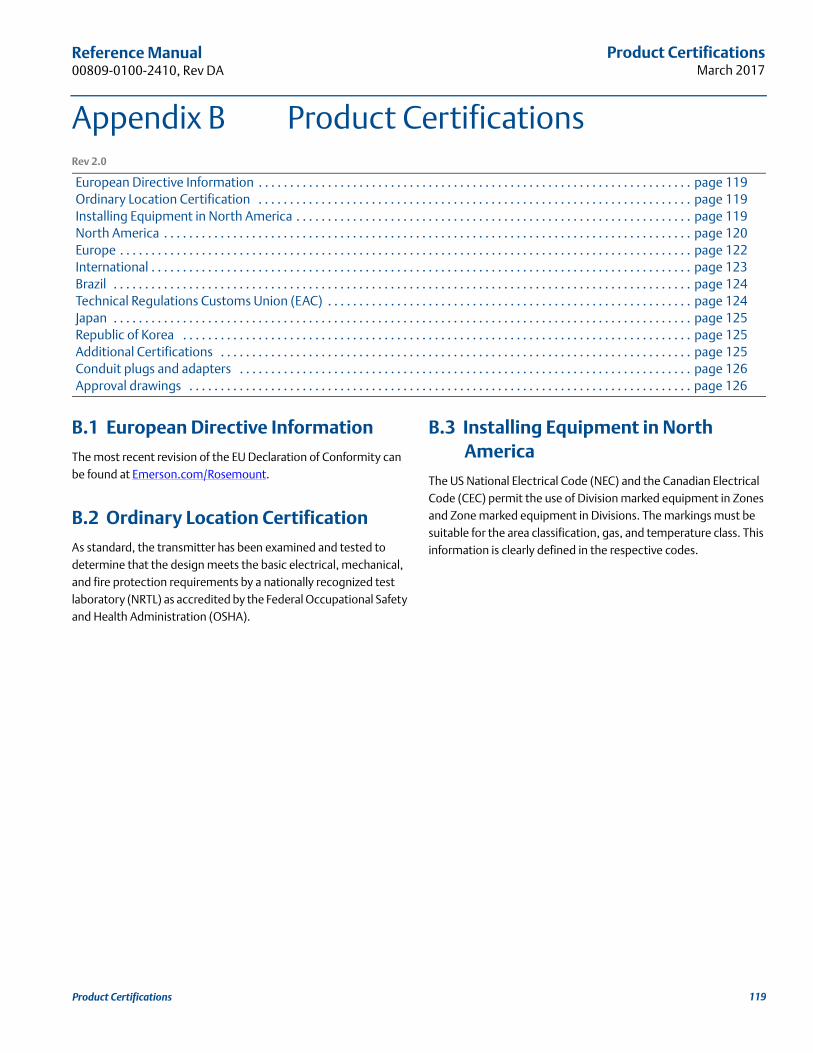
Product CertificationsMarch 2017
Reference Manual 00809-0100-2410, Rev DA
Appendix B Product CertificationsRev 2.0
European Directive Information . . . . . . . . . . . . . . . . . . . . . . . . . . . . . . . . . . . . . . . . . . . . . . . . . . . . . . . . . . . . . . . . . . . . . page 119Ordinary Location Certification . . . . . . . . . . . . . . . . . . . . . . . . . . . . . . . . . . . . . . . . . . . . . . . . . . . . . . . . . . . . . . . . . . . . . page 119Installing Equipment in North America . . . . . . . . . . . . . . . . . . . . . . . . . . . . . . . . . . . . . . . . . . . . . . . . . . . . . . . . . . . . . . . page 119North America . . . . . . . . . . . . . . . . . . . . . . . . . . . . . . . . . . . . . . . . . . . . . . . . . . . . . . . . . . . . . . . . . . . . . . . . . . . . . . . . . . . . page 120Europe . . . . . . . . . . . . . . . . . . . . . . . . . . . . . . . . . . . . . . . . . . . . . . . . . . . . . . . . . . . . . . . . . . . . . . . . . . . . . . . . . . . . . . . . . . . page 122International . . . . . . . . . . . . . . . . . . . . . . . . . . . . . . . . . . . . . . . . . . . . . . . . . . . . . . . . . . . . . . . . . . . . . . . . . . . . . . . . . . . . . . page 123Brazil . . . . . . . . . . . . . . . . . . . . . . . . . . . . . . . . . . . . . . . . . . . . . . . . . . . . . . . . . . . . . . . . . . . . . . . . . . . . . . . . . . . . . . . . . . . . page 124Technical Regulations Customs Union (EAC) . . . . . . . . . . . . . . . . . . . . . . . . . . . . . . . . . . . . . . . . . . . . . . . . . . . . . . . . . . page 124Japan . . . . . . . . . . . . . . . . . . . . . . . . . . . . . . . . . . . . . . . . . . . . . . . . . . . . . . . . . . . . . . . . . . . . . . . . . . . . . . . . . . . . . . . . . . . . page 125Republic of Korea . . . . . . . . . . . . . . . . . . . . . . . . . . . . . . . . . . . . . . . . . . . . . . . . . . . . . . . . . . . . . . . . . . . . . . . . . . . . . . . . . page 125Additional Certifications . . . . . . . . . . . . . . . . . . . . . . . . . . . . . . . . . . . . . . . . . . . . . . . . . . . . . . . . . . . . . . . . . . . . . . . . . . . page 125Conduit plugs and adapters . . . . . . . . . . . . . . . . . . . . . . . . . . . . . . . . . . . . . . . . . . . . . . . . . . . . . . . . . . . . . . . . . . . . . . . . page 126Approval drawings . . . . . . . . . . . . . . . . . . . . . . . . . . . . . . . . . . . . . . . . . . . . . . . . . . . . . . . . . . . . . . . . . . . . . . . . . . . . . . . . page 126
B.1 European Directive Information
The most recent revision of the EU Declaration of Conformity can be found at Emerson.com/Rosemount.
B.2 Ordinary Location Certification
As standard, the transmitter has been examined and tested to determine that the design meets the basic electrical, mechanical, and fire protection requirements by a nationally recognized test laboratory (NRTL) as accredited by the Federal Occupational Safety and Health Administration (OSHA).
B.3 Installing Equipment in North America
The US National Electrical Code (NEC) and the Canadian Electrical Code (CEC) permit the use of Division marked equipment in Zones and Zone marked equipment in Divisions. The markings must be suitable for the area classification, gas, and temperature class. This information is clearly defined in the respective codes.
119Product Certifications
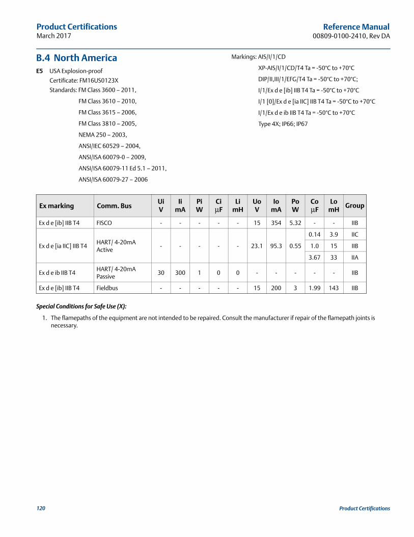
Product CertificationsMarch 2017
Reference Manual00809-0100-2410, Rev DA
B.4 North AmericaE5 USA Explosion-proof
Certificate: FM16US0123X
Standards: FM Class 3600 – 2011,
FM Class 3610 – 2010,
FM Class 3615 – 2006,
FM Class 3810 – 2005,
NEMA 250 – 2003,
ANSI/IEC 60529 – 2004,
ANSI/ISA 60079-0 – 2009,
ANSI/ISA 60079-11 Ed 5.1 – 2011,
ANSI/ISA 60079-27 – 2006
Markings: AIS/I/1/CD
XP-AIS/I/1/CD/T4 Ta = -50°C to +70°C
DIP/II,III/1/EFG/T4 Ta = -50°C to +70°C;
I/1/Ex d e [ib] IIB T4 Ta = -50°C to +70°C
I/1 [0]/Ex d e [ia IIC] IIB T4 Ta = -50°C to +70°C
I/1/Ex d e ib IIB T4 Ta = -50°C to +70°C
Type 4X; IP66; IP67
Special Conditions for Safe Use (X):
1. The flamepaths of the equipment are not intended to be repaired. Consult the manufacturer if repair of the flamepath joints is necessary.
Ex marking Comm. BusUiV
IimA
PiW
CiμF
LimH
UoV
IomA
PoW
CoμF
LomH
Group
Ex d e [ib] IIB T4 FISCO - - - - - 15 354 5.32 - - IIB
Ex d e [ia IIC] IIB T4HART/ 4-20mA Active
- - - - - 23.1 95.3 0.55
0.14 3.9 IIC
1.0 15 IIB
3.67 33 IIA
Ex d e ib IIB T4HART/ 4-20mA Passive
30 300 1 0 0 - - - - - IIB
Ex d e [ib] IIB T4 Fieldbus - - - - - 15 200 3 1.99 143 IIB
120 Product Certifications
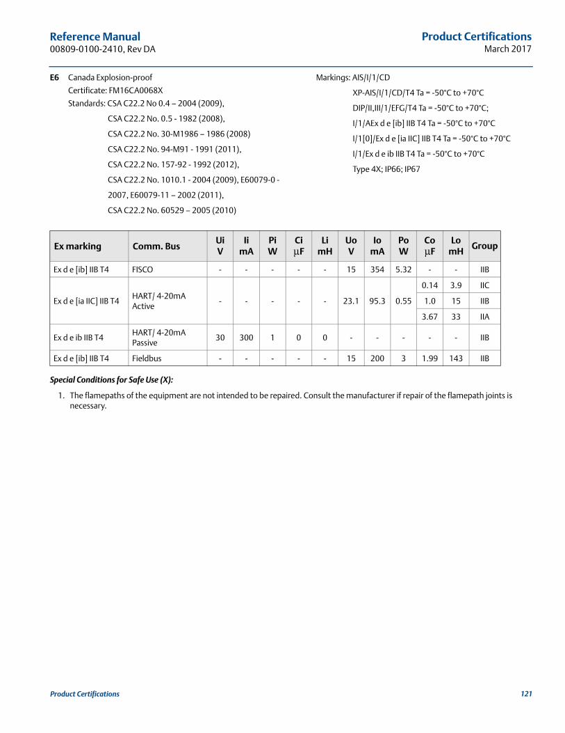
Product CertificationsMarch 2017
Reference Manual 00809-0100-2410, Rev DA
E6 Canada Explosion-proof
Certificate: FM16CA0068X
Standards: CSA C22.2 No 0.4 – 2004 (2009),
CSA C22.2 No. 0.5 - 1982 (2008),
CSA C22.2 No. 30-M1986 – 1986 (2008)
CSA C22.2 No. 94-M91 - 1991 (2011),
CSA C22.2 No. 157-92 - 1992 (2012),
CSA C22.2 No. 1010.1 - 2004 (2009), E60079-0 -
2007, E60079-11 – 2002 (2011),
CSA C22.2 No. 60529 – 2005 (2010)
Markings: AIS/I/1/CD
XP-AIS/I/1/CD/T4 Ta = -50°C to +70°C
DIP/II,III/1/EFG/T4 Ta = -50°C to +70°C;
I/1/AEx d e [ib] IIB T4 Ta = -50°C to +70°C
I/1[0]/Ex d e [ia IIC] IIB T4 Ta = -50°C to +70°C
I/1/Ex d e ib IIB T4 Ta = -50°C to +70°C
Type 4X; IP66; IP67
Special Conditions for Safe Use (X):
1. The flamepaths of the equipment are not intended to be repaired. Consult the manufacturer if repair of the flamepath joints is necessary.
Ex marking Comm. BusUiV
IimA
PiW
CiμF
LimH
UoV
IomA
PoW
CoμF
LomH
Group
Ex d e [ib] IIB T4 FISCO - - - - - 15 354 5.32 - - IIB
Ex d e [ia IIC] IIB T4HART/ 4-20mA Active
- - - - - 23.1 95.3 0.55
0.14 3.9 IIC
1.0 15 IIB
3.67 33 IIA
Ex d e ib IIB T4HART/ 4-20mA Passive
30 300 1 0 0 - - - - - IIB
Ex d e [ib] IIB T4 Fieldbus - - - - - 15 200 3 1.99 143 IIB
121Product Certifications
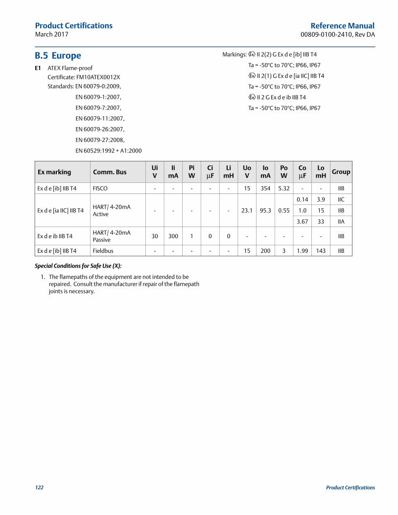
Product CertificationsMarch 2017
Reference Manual00809-0100-2410, Rev DA
B.5 EuropeE1 ATEX Flame-proof
Certificate: FM10ATEX0012X
Standards: EN 60079-0:2009,
EN 60079-1:2007,
EN 60079-7:2007,
EN 60079-11:2007,
EN 60079-26:2007,
EN 60079-27:2008,
EN 60529:1992 + A1:2000
Markings: II 2(2) G Ex d e [ib] IIB T4
Ta = -50°C to 70°C; IP66, IP67
II 2(1) G Ex d e [ia IIC] IIB T4
Ta = -50°C to 70°C; IP66, IP67
II 2 G Ex d e ib IIB T4
Ta = -50°C to 70°C; IP66, IP67
Special Conditions for Safe Use (X):
1. The flamepaths of the equipment are not intended to be repaired. Consult the manufacturer if repair of the flamepath joints is necessary.
Ex marking Comm. BusUiV
IimA
PiW
CiμF
LimH
UoV
IomA
PoW
CoμF
LomH
Group
Ex d e [ib] IIB T4 FISCO - - - - - 15 354 5.32 - - IIB
Ex d e [ia IIC] IIB T4HART/ 4-20mA Active
- - - - - 23.1 95.3 0.55
0.14 3.9 IIC
1.0 15 IIB
3.67 33 IIA
Ex d e ib IIB T4HART/ 4-20mA Passive
30 300 1 0 0 - - - - - IIB
Ex d e [ib] IIB T4 Fieldbus - - - - - 15 200 3 1.99 143 IIB
122 Product Certifications
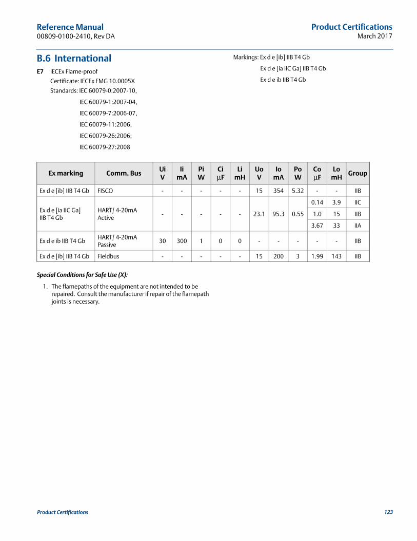
Product CertificationsMarch 2017
Reference Manual 00809-0100-2410, Rev DA
B.6 InternationalE7 IECEx Flame-proof
Certificate: IECEx FMG 10.0005X
Standards: IEC 60079-0:2007-10,
IEC 60079-1:2007-04,
IEC 60079-7:2006-07,
IEC 60079-11:2006,
IEC 60079-26:2006;
IEC 60079-27:2008
Markings: Ex d e [ib] IIB T4 Gb
Ex d e [ia IIC Ga] IIB T4 Gb
Ex d e ib IIB T4 Gb
Special Conditions for Safe Use (X):
1. The flamepaths of the equipment are not intended to be repaired. Consult the manufacturer if repair of the flamepath joints is necessary.
Ex marking Comm. BusUiV
IimA
PiW
CiμF
LimH
UoV
IomA
PoW
CoμF
LomH
Group
Ex d e [ib] IIB T4 Gb FISCO - - - - - 15 354 5.32 - - IIB
Ex d e [ia IIC Ga] IIB T4 Gb
HART/ 4-20mA Active
- - - - - 23.1 95.3 0.55
0.14 3.9 IIC
1.0 15 IIB
3.67 33 IIA
Ex d e ib IIB T4 GbHART/ 4-20mA Passive
30 300 1 0 0 - - - - - IIB
Ex d e [ib] IIB T4 Gb Fieldbus - - - - - 15 200 3 1.99 143 IIB
123Product Certifications
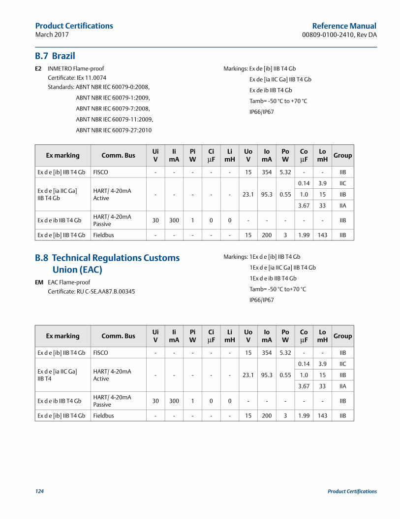
Product CertificationsMarch 2017
Reference Manual00809-0100-2410, Rev DA
B.7 BrazilE2 INMETRO Flame-proof
Certificate: IEx 11.0074
Standards: ABNT NBR IEC 60079-0:2008,
ABNT NBR IEC 60079-1:2009,
ABNT NBR IEC 60079-7:2008,
ABNT NBR IEC 60079-11:2009,
ABNT NBR IEC 60079-27:2010
Markings: Ex de [ib] IIB T4 Gb
Ex de [ia IIC Ga] IIB T4 Gb
Ex de ib IIB T4 Gb
Tamb= -50 °C to +70 °C
IP66/IP67
B.8 Technical Regulations Customs Union (EAC)
EM EAC Flame-proof
Certificate: RU C-SE.AA87.B.00345
Markings: 1Ex d e [ib] IIB T4 Gb
1Ex d e [ia IIC Ga] IIB T4 Gb
1Ex d e ib IIB T4 Gb
Tamb= -50 °C to+70 °C
IP66/IP67
Ex marking Comm. BusUiV
IimA
PiW
CiμF
LimH
UoV
IomA
PoW
CoμF
LomH
Group
Ex d e [ib] IIB T4 Gb FISCO - - - - - 15 354 5.32 - - IIB
Ex d e [ia IIC Ga] IIB T4 Gb
HART/ 4-20mA Active
- - - - - 23.1 95.3 0.55
0.14 3.9 IIC
1.0 15 IIB
3.67 33 IIA
Ex d e ib IIB T4 GbHART/ 4-20mA Passive
30 300 1 0 0 - - - - - IIB
Ex d e [ib] IIB T4 Gb Fieldbus - - - - - 15 200 3 1.99 143 IIB
Ex marking Comm. BusUiV
IimA
PiW
CiμF
LimH
UoV
IomA
PoW
CoμF
LomH
Group
Ex d e [ib] IIB T4 Gb FISCO - - - - - 15 354 5.32 - - IIB
Ex d e [ia IIC Ga] IIB T4
HART/ 4-20mA Active
- - - - - 23.1 95.3 0.55
0.14 3.9 IIC
1.0 15 IIB
3.67 33 IIA
Ex d e ib IIB T4 GbHART/ 4-20mA Passive
30 300 1 0 0 - - - - - IIB
Ex d e [ib] IIB T4 Gb Fieldbus - - - - - 15 200 3 1.99 143 IIB
124 Product Certifications
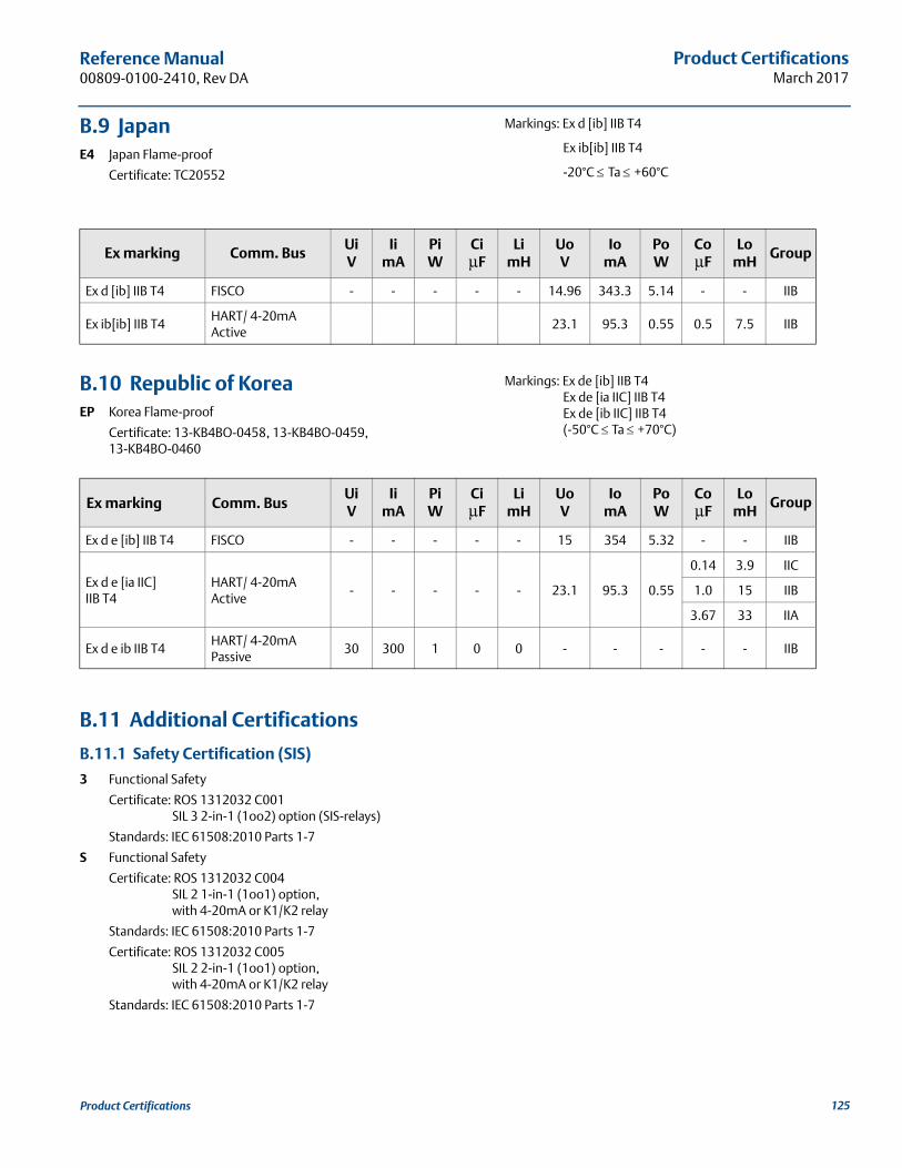
Product CertificationsMarch 2017
Reference Manual 00809-0100-2410, Rev DA
B.9 JapanE4 Japan Flame-proof
Certificate: TC20552
Markings: Ex d [ib] IIB T4
Ex ib[ib] IIB T4
-20°C Ta +60°C
B.10 Republic of KoreaEP Korea Flame-proof
Certificate: 13-KB4BO-0458, 13-KB4BO-0459, 13-KB4BO-0460
Markings: Ex de [ib] IIB T4Ex de [ia IIC] IIB T4Ex de [ib IIC] IIB T4(-50°C Ta +70°C)
B.11 Additional Certifications
B.11.1 Safety Certification (SIS)
3 Functional Safety
Certificate: ROS 1312032 C001SIL 3 2-in-1 (1oo2) option (SIS-relays)
Standards: IEC 61508:2010 Parts 1-7
S Functional Safety
Certificate: ROS 1312032 C004SIL 2 1-in-1 (1oo1) option, with 4-20mA or K1/K2 relay
Standards: IEC 61508:2010 Parts 1-7
Certificate: ROS 1312032 C005SIL 2 2-in-1 (1oo1) option, with 4-20mA or K1/K2 relay
Standards: IEC 61508:2010 Parts 1-7
Ex marking Comm. BusUiV
IimA
PiW
CiμF
LimH
UoV
IomA
PoW
CoμF
LomH
Group
Ex d [ib] IIB T4 FISCO - - - - - 14.96 343.3 5.14 - - IIB
Ex ib[ib] IIB T4HART/ 4-20mA Active
23.1 95.3 0.55 0.5 7.5 IIB
Ex marking Comm. BusUiV
IimA
PiW
CiμF
LimH
UoV
IomA
PoW
CoμF
LomH
Group
Ex d e [ib] IIB T4 FISCO - - - - - 15 354 5.32 - - IIB
Ex d e [ia IIC] IIB T4
HART/ 4-20mA Active
- - - - - 23.1 95.3 0.55
0.14 3.9 IIC
1.0 15 IIB
3.67 33 IIA
Ex d e ib IIB T4HART/ 4-20mA Passive
30 300 1 0 0 - - - - - IIB
125Product Certifications
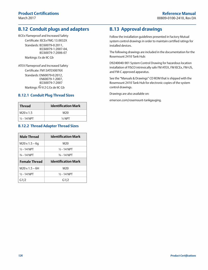
Product CertificationsMarch 2017
Reference Manual00809-0100-2410, Rev DA
B.12 Conduit plugs and adaptersIECEx Flameproof and Increased Safety
Certificate: IECEx FMG 13.0032X
Standards: IEC60079-0:2011, IEC60079-1:2007-04, IEC60079-7:2006-07
Markings: Ex de IIC Gb
ATEX Flameproof and Increased Safety
Certificate: FM13ATEX0076X
Standards: EN60079-0:2012, EN60079-1:2007, IEC60079-7:2007
Markings: II 2 G Ex de IIC Gb
B.12.1 Conduit Plug Thread Sizes
B.12.2 Thread Adapter Thread Sizes
B.13 Approval drawings
Follow the installation guidelines presented in Factory Mutual system control drawings in order to maintain certified ratings for installed devices.
The following drawings are included in the documentation for the Rosemount 2410 Tank Hub:
D9240040-901 System Control Drawing for hazardous location installation of FISCO intrinsically safe FM ATEX, FM IECEx, FM-US, and FM-C approved apparatus.
See the “Manuals & Drawings” CD ROM that is shipped with the Rosemount 2410 Tank Hub for electronic copies of the system control drawings.
Drawings are also available on:
emerson.com/rosemount-tankgauging.
Thread Identification Mark
M20 x 1.5 M20
½ - 14 NPT ½ NPT
Male Thread Identification Mark
M20 x 1.5 – 6g M20
½ - 14 NPT ½ - 14 NPT
¾ - 14 NPT ¾ - 14 NPT
Female Thread Identification Mark
M20 x 1.5 – 6H M20
½ - 14 NPT ½ - 14 NPT
G1/2 G1/2
126 Product Certifications
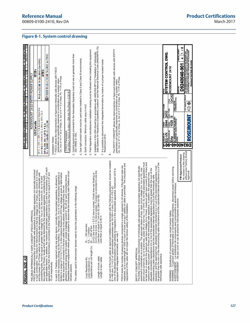
Product CertificationsMarch 2017
Reference Manual 00809-0100-2410, Rev DA
Figure B-1. System control drawing
No
revi
sion
to th
is d
raw
ing
with
out p
rior F
acto
ry M
utua
lAp
prov
al.
FM A
ppro
ved
Pro
duct
FIEL
DBU
S IN
TRIN
SIC
ALLY
SAF
E C
ON
CEP
T (F
ISC
O) A
PPR
OVA
LFI
SCO
allo
ws
inte
rcon
nect
ion
of in
trins
ical
ly s
afe
appa
ratu
s to
ass
ocia
ted
appa
ratu
s no
t spe
cial
ly e
xam
ined
in s
uch
com
bina
tion.
The
crit
eria
for i
nter
conn
ectio
n is
that
the
volta
ge (U
i or V
max
), th
e cu
rrent
(Ii o
r Im
ax),
and
the
pow
er (P
i or P
max
) whi
ch a
n in
trins
ical
ly s
afe
appa
ratu
s ca
n re
ceiv
e an
d re
mai
n in
trins
ical
ly s
afe
cons
ider
ing
faul
ts, m
ust b
e eq
ual o
r gre
ater
than
vol
tage
(Uo,
Voc
or V
t), th
e cu
rrent
(Io,
Isc
or It
) and
the
pow
er (P
o or
Pm
ax)
leve
ls w
hich
can
be
deliv
ered
by
the
asso
ciat
ed a
ppar
atus
, con
side
ring
faul
tsan
d ap
plic
able
fact
ors.
In a
dditi
on, t
he m
axim
um u
npro
tect
ed c
apac
itanc
e (C
i) an
d th
e in
duct
ance
(Li)
of e
ach
appa
ratu
s (o
ther
than
the
term
inat
ion)
con
ncec
ted
to th
e Fi
eldb
us m
ust b
e le
ss th
an o
r equ
al to
5 n
F an
d10
uH
resp
ectiv
ely.
In e
ach
I.S. F
ield
bus
segm
ent o
nly
one
activ
e de
vice
, nor
mal
ly th
e as
soci
ated
app
arat
us, i
s al
low
ed to
pr
ovid
e th
e ne
cess
ary
ener
gy fo
r the
Fie
ldbu
s. T
he v
olta
ge (U
o, V
oc o
r Vt)
of th
e as
soci
ated
app
arat
us is
lim
ited
to a
rang
e of
14
V to
17.
5 V.
In th
is in
stan
ce R
osem
ount
241
0 ha
s vo
ltage
as
give
n in
tabl
e be
low
. Al
l oth
er e
quip
men
t con
nect
ed to
the
bus
cabl
e ha
s to
be
pass
ive,
mea
ning
that
they
are
not
al
low
ed to
pro
vide
ene
rgy
to th
e sy
stem
, exc
ept a
leak
age
curre
nt o
f 50
uA
for e
ach
conn
ecte
d de
vice
. Se
para
tely
pow
ered
equ
ipm
ent n
eeds
gal
vani
c is
olat
ion
to a
ssur
e th
at th
e in
trins
ical
ly s
afe
Fiel
dbus
circ
uit
rem
ains
pas
sive
.
The
cabl
es u
sed
to in
terc
onne
ct d
evic
es n
eed
to h
ave
the
para
met
ers
in th
e fo
llow
ing
rang
e:
Loop
Res
ista
nce
Rc:
Lo
op In
duct
ance
Lc:
Cap
acita
nce
per u
nit l
engt
h C
c:
Leng
th o
f tru
nk c
able
:Le
ngth
of s
pur c
able
:
15...
...15
0 oh
m/k
m0.
4....
.1 m
H/k
m45
......
200
nF/k
mC
c=C
c lin
e to
line
+ 0
.5 C
c lin
e to
scr
een,
if b
oth
lines
are
floa
ting
orC
c=C
c lin
e to
line
+ C
c lin
e to
scr
een,
if s
cree
n is
con
ncte
d to
one
line
Less
than
or e
qual
to 1
km
for I
IC (5
km fo
r IIB
)Le
ss th
an o
r equ
al to
60
m
At e
ach
end
of th
e tru
nk c
able
an
appr
oved
infa
llible
line
term
inat
or w
ith th
e fo
llow
ing
para
met
ers
shou
ld b
e in
stal
led:
R >
=90
ohm
, C <
=2.2
uF
(reco
mm
ende
d pa
ram
eter
s ar
e: R
=100
+/-2
ohm
, C=1
.0 +
/-0.2
uF)
One
of t
he a
llow
ed te
rmin
atio
ns m
ight
alre
ady
be in
tegr
ated
in th
e as
soci
ated
app
arat
us. R
osem
ount
241
0 is
eq
uipp
ed w
ith in
tegr
ated
term
inat
ion,
see
not
e 7.
FISC
O li
mits
the
num
ber o
f pas
sive
dev
ices
con
nect
ed to
a s
ingl
e se
gmen
t to
32 d
evic
es. I
f the
abo
ve ru
les
are
resp
ecte
d, u
p to
a to
tal l
engt
h of
100
0 m
(sum
of t
runk
and
spu
r cab
les)
of c
able
is p
erm
itted
. The
indu
ctan
ce a
nd
capa
cita
nce
of th
e ca
ble
will
not i
mpa
ir th
e in
trins
ic s
afet
y of
the
inst
alla
tion.
FISC
O a
llow
s th
e in
terc
onne
ctio
n of
App
rove
d in
trisi
cally
saf
e de
vice
s w
ith F
ISC
Opa
ram
eter
s no
t spe
cific
ally
exa
min
ed in
com
bina
tion
as a
sys
tem
whe
n:U
o, V
oc o
r Vt =
< U
i or V
max
, Io,
Ioc
or It
=<
Ii or
Imax
, Po
=<
Pi o
r Pm
ax
Inst
alla
tion
Not
es:
1. 2. 3. 4. 5. 6. 7. 8.
Con
trol e
quip
men
t con
nect
ed to
the
Asso
ciat
es A
ppar
atus
mus
t not
use
or g
ener
ate
mor
e th
an
250
VRM
S or
VD
C.
Dus
t tig
ht c
ondu
it se
als
mus
t be
used
whe
n in
stal
led
in C
lass
II a
nd C
lass
III e
nviro
nmen
ts.
Earth
con
nect
ion.
Min
imum
cab
le a
rea
4 m
m2
Fiel
d Ap
para
tus
man
ufac
ture
rs in
stal
latio
n dr
awin
g m
ust b
e fo
llow
ed w
hen
inst
allin
g th
is e
quip
men
t.
Inst
alla
tion
in th
e U
SA s
houl
d be
in a
ccor
danc
e w
ith A
NSI
/ISA-
RP1
2.6
"Inst
alla
tion
of In
trins
ical
lySa
fe S
yste
ms
for H
azar
dous
(Cla
ssifi
ed) L
ocat
ions
" and
the
Nat
iona
l Ele
ctric
al C
ode
(AN
SI/N
FPA
70).
It is
pos
sibl
e to
dis
conn
ect t
he in
tegr
ated
term
inat
ion
by m
eans
of a
jum
per l
ocat
ed in
side
Ros
emou
nt 2
410.
1SM
E-60
9610
29SM
E-69
892
1113
WAR
NIN
G -
Sub
stitu
tion
of c
ompo
nent
s m
ay im
pair
Intri
nsic
Saf
ety.
W
ARN
ING
- T
o pr
even
t ign
ition
of f
lam
mab
le o
r com
bust
ible
atm
osph
eres
, dis
conn
ect p
ower
bef
ore
serv
icin
g.
AVER
TISS
EMEN
T -
La s
ubst
itutio
n de
com
posa
nts
peut
com
prom
ettre
la s
écur
ité in
trins
èque
. AV
ERTI
SSEM
ENT
- N
e pa
s ou
vrir
en c
as d
e pr
esen
ce d
'atm
osph
ere
expl
osiv
e.
ENTI
TY C
ON
CEP
T AP
PRO
VAL
The
Entit
y co
ncep
t allo
ws
inte
rcon
nect
ion
of in
trins
ical
ly s
afe
appa
ratu
s to
ass
ocia
ted
appa
ratu
s no
t spe
cific
ally
exam
ined
in c
ombi
natio
n as
a s
yste
m. T
he a
ppro
ved
valu
es o
f max
. ope
n ci
rcui
t vol
tage
(Uo,
Voc
or V
t), m
ax.
shor
t circ
uit c
urre
nt (I
o, Is
c or
It) a
nd m
ax. p
ower
(Po
or V
oc×I
sc /
4 or
Vt×
It / 4
), fo
r the
ass
ocia
ted
appa
ratu
s m
ust
be le
ss th
an o
r equ
al to
the
max
imum
saf
e in
put v
olta
ge (U
i or V
max
), m
axim
um s
afe
inpu
t cur
rent
(Ii o
r Im
ax) a
ndm
axim
um s
afe
inpu
t pow
er (P
i or P
max
) of t
he in
trins
ical
ly s
afe
appa
ratu
s. In
add
ition
, the
app
rove
d m
ax.
allo
wab
le c
onne
cted
cap
acita
nce
(Co
or C
a) o
f the
ass
ocia
ted
appa
ratu
s m
ust b
e gr
eate
r tha
n th
e su
m o
f the
inte
rcon
nect
ing
cabl
e ca
paci
tanc
e an
d th
e un
prot
ecte
d in
tern
al c
apac
itanc
e (C
i) of
the
intri
nsic
ally
saf
eap
para
tus,
and
the
appr
oved
max
. allo
wab
le c
onne
cted
indu
ctan
ce (L
o or
La)
of t
he a
ssoc
iate
d ap
para
tus
mus
tbe
gre
ater
than
the
sum
of t
he in
terc
onne
ctin
g ca
ble
indu
ctan
ce a
nd th
e un
prot
ecte
d in
tern
al in
duct
ance
(Li)
of th
ein
trins
ical
ly s
afe
appa
ratu
s.
The
ENTI
TY C
ON
CEP
T al
low
s th
e in
terc
onne
ctio
n of
App
rove
d in
trisi
cally
saf
e de
vice
s w
ith E
NTI
TYpa
ram
eter
s no
t spe
cific
ally
exa
min
ed in
com
bina
tion
as a
sys
tem
whe
n:U
o, V
oc o
r Vt =
< U
i or V
max
, Io,
Ioc
or It
=<
Ii or
Imax
, Po
=<
Pi o
r Pm
ax.
FISC
O P
aram
eter
s:U
o (V
oc) =
15.
0 V;
Io (I
sc) =
354
mA;
Po
(Pou
t) =
5.32
W3SM
E-82
5915
254
SME-
8531
1629
ISS
UE
D B
Y
AP
PR
OV
ED
BY
WE
EK
WE
EK
PR
OD
UC
T C
OD
E
DO
C.
TY
PE
FIL
E
TIT
LE
DW
G N
O.
ISS
UE
SH
EE
T
SC
AL
E1
ST
AN
GL
ETh
e co
pyrig
ht/o
wne
rshi
p of
this
doc
umen
t is
and
will
rem
ain
ours
.Th
e do
cum
ent m
ust n
ot b
e us
ed w
ithou
t our
aut
horiz
atio
n or
bro
ught
to th
e kn
owle
dge
of a
third
par
ty. C
ontra
vent
ion
will
be p
rose
cute
d.
Ros
emou
nt T
ank
Rad
ar A
B, S
wed
en
ALL
DIM
ENSI
ON
S AR
E IN
MIL
LIM
ETR
ES.
TO
LER
ANC
ES, U
NLE
SS O
THER
WIS
EST
ATED
:
FIN
ISH
, UN
LESS
OTH
ERW
ISE
STAT
ED:
EE-V
N
1029
2410
EAp
6��
���
D9240040-901D
9240
040-
901
0844
SYST
EM C
ON
TRO
L D
WG
.
4/
RO
SEM
OU
NT
2410
18
ISS
UE
CH
. O
RD
ER
No
WE
EK
ISS
UE
CH
. O
RD
ER
No
WE
EK
ISS
UE
CH
. O
RD
ER
No
WE
EK
ISS
UE
CH
. O
RD
ER
No
WE
EK
ISS
UE
CH
. O
RD
ER
No
WE
EK
ISS
UE
CH
. O
RD
ER
No
WE
EK
ISS
UE
CH
. O
RD
ER
No
WE
EK
ISS
UE
CH
. O
RD
ER
No
WE
EK
ISS
UE
CH
. O
RD
ER
No
WE
EK
ISS
UE
CH
. O
RD
ER
No
WE
EK
ISS
UE
CH
. O
RD
ER
No
WE
EK
ISS
UE
CH
. O
RD
ER
No
WE
EK
OR
IGIN
AL S
IZE
A3O
RIG
INAL
SIZ
EA3
OR
IGIN
AL S
IZE
A3
127Product Certifications

Product CertificationsMarch 2017
Reference Manual00809-0100-2410, Rev DA
No
revi
sion
to th
is d
raw
ing
with
out p
rior F
acto
ry M
utua
lAp
prov
al.
FM A
ppro
ved
Pro
duct
ANY
APPR
OVE
DFI
SCO
FIE
LDD
EVIC
E
APPR
OVE
DFI
SCO
TER
MIN
ATO
RN
ON
ISU
NSP
ECIF
IED
CO
NTR
OL
EQU
IPM
ENT
(Not
e 2)
NO
N-H
AZAR
DO
US
OR
ZO
NE
1 / D
IVIS
ION
1, G
AS G
RO
UP
C &
D /
IIB H
AZAR
DO
US
AREA
HAZ
ARD
OU
S AR
EAN
ON
-HAZ
ARD
OU
SAR
EA
1SM
E-60
96
Not
es: 3
, 4, 5
, 6,
IS
1029
2SM
E-69
8911
13
OPT
ION
ALIN
TRIN
SIC
ALLY
SAFE
I/O
34
SME-
8259
SME-
8531
1525
1629
ISS
UE
D B
Y
AP
PR
OV
ED
BY
WE
EK
WE
EK
PR
OD
UC
T C
OD
E
DO
C.
TY
PE
FIL
E
TIT
LE
DW
G N
O.
ISS
UE
SH
EE
T
SC
AL
E1
ST
AN
GL
ETh
e co
pyrig
ht/o
wne
rshi
p of
this
doc
umen
t is
and
will
rem
ain
ours
.Th
e do
cum
ent m
ust n
ot b
e us
ed w
ithou
t our
aut
horiz
atio
n or
bro
ught
to th
e kn
owle
dge
of a
third
par
ty. C
ontra
vent
ion
will
be p
rose
cute
d.
Ros
emou
nt T
ank
Rad
ar A
B, S
wed
en
ALL
DIM
ENSI
ON
S AR
E IN
MIL
LIM
ETR
ES.
TO
LER
ANC
ES, U
NLE
SS O
THER
WIS
EST
ATED
:
FIN
ISH
, UN
LESS
OTH
ERW
ISE
STAT
ED:
EE-V
N
1029
2410
EAp
6��
���
D9240040-901D
9240
040-
901
0844
SYST
EM C
ON
TRO
L D
WG
.
4/
RO
SE
MO
UN
T 24
10
(INS
TALL
ATIO
N O
VER
VIEW
) 28
ISS
UE
D B
Y
AP
PR
OV
ED
BY
WE
EK
WE
EK
PR
OD
UC
T C
OD
E
DO
C.
TY
PE
FIL
E
TIT
LE
DW
G N
O.
ISS
UE
SH
EE
T
SC
AL
E1
ST
AN
GL
ETh
e co
pyrig
ht/o
wne
rshi
p of
this
doc
umen
t is
and
will
rem
ain
ours
.Th
e do
cum
ent m
ust n
ot b
e us
ed w
ithou
t our
aut
horiz
atio
n or
bro
ught
to th
e kn
owle
dge
of a
third
par
ty. C
ontra
vent
ion
will
be p
rose
cute
d.
Ros
emou
nt T
ank
Rad
ar A
B, S
wed
en
ALL
DIM
ENSI
ON
S AR
E IN
MIL
LIM
ETR
ES.
TO
LER
ANC
ES, U
NLE
SS O
THER
WIS
EST
ATED
:
FIN
ISH
, UN
LESS
OTH
ERW
ISE
STAT
ED:
EE-V
N
1029
2410
EAp
6��
���
D9240040-901D
9240
040-
901
0844
SYST
EM C
ON
TRO
L D
WG
.
4/
RO
SE
MO
UN
T 24
10
(INS
TALL
ATIO
N O
VER
VIEW
) 28
OR
IGIN
AL S
IZE
A3O
RIG
INAL
SIZ
EA3
OR
IGIN
AL S
IZE
A3IS
SU
EC
H. O
RD
ER
No
WE
EK
ISS
UE
CH
. O
RD
ER
No
WE
EK
ISS
UE
CH
. O
RD
ER
No
WE
EK
ISS
UE
CH
. O
RD
ER
No
WE
EK
ISS
UE
CH
. O
RD
ER
No
WE
EK
ISS
UE
CH
. O
RD
ER
No
WE
EK
ISS
UE
CH
. O
RD
ER
No
WE
EK
ISS
UE
CH
. O
RD
ER
No
WE
EK
ISS
UE
CH
. O
RD
ER
No
WE
EK
ISS
UE
CH
. O
RD
ER
No
WE
EK
ISS
UE
CH
. O
RD
ER
No
WE
EK
ISS
UE
CH
. O
RD
ER
No
WE
EK
128 Product Certifications
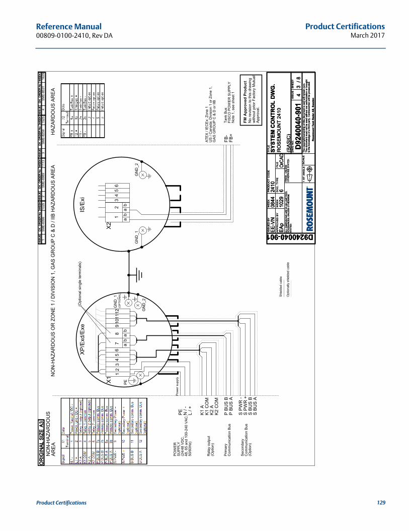
Product CertificationsMarch 2017
Reference Manual 00809-0100-2410, Rev DA
NO
N-H
AZAR
DO
US
OR
ZO
NE
1 / D
IVIS
ION
1, G
AS G
RO
UP
C &
D /
IIB H
AZAR
DO
US
AREA
HAZ
ARD
OU
S AR
EA
1 2
L / +
N /
-
34
56
78
910
1112
PE
NO
N-H
AZAR
DO
US
AREA
X1
XP/E
xd/E
xe
K1 C
OM
K2 C
OM
P BU
S B
P BU
S A
POW
ERSU
PPLY
(24/
48 V
DC
,48
, 65
and
100-
240
VAC
,50
/60H
z)
Rel
ay o
utpu
t(O
ptio
n)
Prim
ary
Com
mun
icat
ion
Bus
Shie
lded
cab
le
Opt
iona
lly s
hiel
ded
cabl
e
No
revi
sion
to th
is d
raw
ing
with
out p
rior F
acto
ry M
utua
lAp
prov
al.
FM A
ppro
ved
Pro
duct
PE
GN
D_1
GN
D_2
1SM
E-60
96
K1 A
K2 A
S BU
S A
S PW
R -
S BU
S B
S PW
R +
Pow
er s
uppl
y
Seco
ndar
yC
omm
unic
atio
n Bu
s(O
ptio
n)
ab
ab
FB-
FB+
X2
Tank
Bus
FISC
O P
OW
ER S
UPP
LYN
ote
1, s
ee s
heet
1
34
56
GN
D_1
GN
D_2
IS/E
xi
1210
292
SME-
6989
1113
ab
ba
(Opt
iona
l sin
gle
term
inal
s)
(OPT
ION
AL)
ATEX
/ IE
CEx
: Zon
e 1
US
/ Can
ada:
Div
isio
n 1
or Z
one
1,G
AS G
RO
UP
C &
D o
r IIB
34
SME-
8259
SME-
8531
1525
1629
ISS
UE
D B
Y
AP
PR
OV
ED
BY
WE
EK
WE
EK
PR
OD
UC
T C
OD
E
DO
C.
TY
PE
FIL
E
TIT
LE
DW
G N
O.
ISS
UE
SH
EE
T
SC
AL
E1
ST
AN
GL
ETh
e co
pyrig
ht/o
wne
rshi
p of
this
doc
umen
t is
and
will
rem
ain
ours
.Th
e do
cum
ent m
ust n
ot b
e us
ed w
ithou
t our
aut
horiz
atio
n or
bro
ught
to th
e kn
owle
dge
of a
third
par
ty. C
ontra
vent
ion
will
be p
rose
cute
d.
Ros
emou
nt T
ank
Rad
ar A
B, S
wed
en
ALL
DIM
ENSI
ON
S AR
E IN
MIL
LIM
ETR
ES.
TO
LER
ANC
ES, U
NLE
SS O
THER
WIS
EST
ATED
:
FIN
ISH
, UN
LESS
OTH
ERW
ISE
STAT
ED:
EE-V
N
1029
2410
EAp
6��
���
D9240040-901D
9240
040-
901
0844
SYST
EM C
ON
TRO
L D
WG
.
4/
RO
SEM
OU
NT
2410
(BAS
IC)
38
ISS
UE
CH
. O
RD
ER
No
WE
EK
ISS
UE
CH
. O
RD
ER
No
WE
EK
ISS
UE
CH
. O
RD
ER
No
WE
EK
ISS
UE
CH
. O
RD
ER
No
WE
EK
ISS
UE
CH
. O
RD
ER
No
WE
EK
ISS
UE
CH
. O
RD
ER
No
WE
EK
ISS
UE
CH
. O
RD
ER
No
WE
EK
ISS
UE
CH
. O
RD
ER
No
WE
EK
ISS
UE
CH
. O
RD
ER
No
WE
EK
ISS
UE
CH
. O
RD
ER
No
WE
EK
ISS
UE
CH
. O
RD
ER
No
WE
EK
ISS
UE
CH
. O
RD
ER
No
WE
EK
OR
IGIN
AL S
IZE
A3O
RIG
INAL
SIZ
EA3
OR
IGIN
AL S
IZE
A3
129Product Certifications
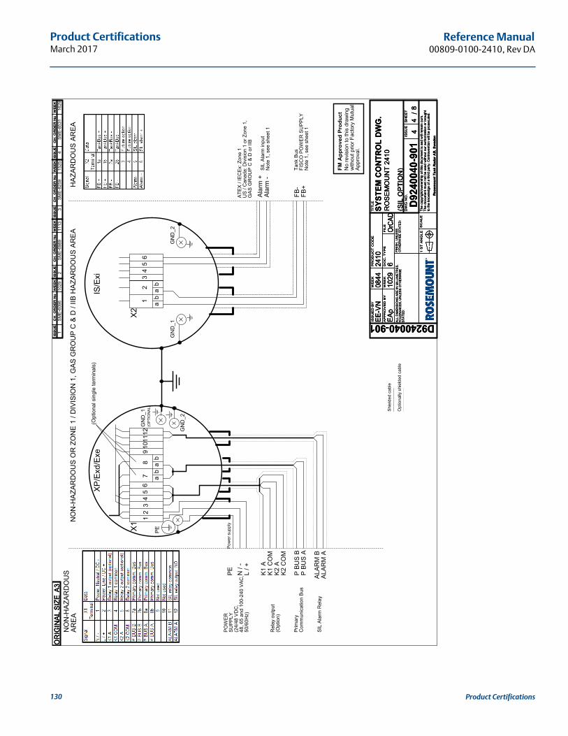
Product CertificationsMarch 2017
Reference Manual00809-0100-2410, Rev DA
NO
N-H
AZAR
DO
US
OR
ZO
NE
1 / D
IVIS
ION
1, G
AS G
RO
UP
C &
D /
IIB H
AZAR
DO
US
AREA
HAZ
ARD
OU
S AR
EAN
ON
-HAZ
ARD
OU
SAR
EA
1SM
E-60
96
No
revi
sion
to th
is d
raw
ing
with
out p
rior F
acto
ry M
utua
lAp
prov
al.
FM A
ppro
ved
Pro
duct
Shie
lded
cab
le
Opt
iona
lly s
hiel
ded
cabl
e
L / +
N /
-
K1 C
OM
K2 C
OM
P BU
S B
P BU
S A
PE
ab
ab
FB-
FB+
X2
Alar
m -
Alar
m +
Tank
Bus
FISC
O P
OW
ER S
UPP
LYN
ote
1, s
ee s
heet
1
34
56
GN
D_1
GN
D_2
SIL
Alar
m in
put
Not
e 1,
see
she
et 1
IS/E
xi
POW
ERSU
PPLY
(24/
48 V
DC
,48
, 65
and
100-
240
VAC
,50
/60H
z)
Rel
ay o
utpu
t(O
ptio
n)
Prim
ary
Com
mun
icat
ion
Bus
K1 A
K2 A
ALAR
M B
ALAR
M A
Pow
er s
uppl
y
12
SIL
Alar
m R
elay
1029
2SM
E-69
8911
13
1 2
a3
b
45
67
8
b
910
1112
a
X1
XP/E
xd/E
xe
(OPT
ION
AL)
PE
GN
D_1
GN
D_2
(Opt
iona
l sin
gle
term
inal
s)
ATEX
/ IE
CEx
: Zon
e 1
US
/ Can
ada:
Div
isio
n 1
or Z
one
1,G
AS G
RO
UP
C &
D o
r IIB
34
SME-
8259
SME-
8531
1525
1629
ISS
UE
D B
Y
AP
PR
OV
ED
BY
WE
EK
WE
EK
PR
OD
UC
T C
OD
E
DO
C.
TY
PE
FIL
E
TIT
LE
DW
G N
O.
ISS
UE
SH
EE
T
SC
AL
E1
ST
AN
GL
ETh
e co
pyrig
ht/o
wne
rshi
p of
this
doc
umen
t is
and
will
rem
ain
ours
.Th
e do
cum
ent m
ust n
ot b
e us
ed w
ithou
t our
aut
horiz
atio
n or
bro
ught
to th
e kn
owle
dge
of a
third
par
ty. C
ontra
vent
ion
will
be p
rose
cute
d.
Ros
emou
nt T
ank
Rad
ar A
B, S
wed
en
ALL
DIM
ENSI
ON
S AR
E IN
MIL
LIM
ETR
ES.
TO
LER
ANC
ES, U
NLE
SS O
THER
WIS
EST
ATED
:
FIN
ISH
, UN
LESS
OTH
ERW
ISE
STAT
ED:
EE-V
N
1029
2410
EAp
6��
���
D9240040-901D
9240
040-
901
0844
SYST
EM C
ON
TRO
L D
WG
.
4/
RO
SEM
OU
NT
2410
(SIL
OPT
ION
)
48
ISS
UE
CH
. O
RD
ER
No
WE
EK
ISS
UE
CH
. O
RD
ER
No
WE
EK
ISS
UE
CH
. O
RD
ER
No
WE
EK
ISS
UE
CH
. O
RD
ER
No
WE
EK
ISS
UE
CH
. O
RD
ER
No
WE
EK
ISS
UE
CH
. O
RD
ER
No
WE
EK
ISS
UE
CH
. O
RD
ER
No
WE
EK
ISS
UE
CH
. O
RD
ER
No
WE
EK
ISS
UE
CH
. O
RD
ER
No
WE
EK
ISS
UE
CH
. O
RD
ER
No
WE
EK
ISS
UE
CH
. O
RD
ER
No
WE
EK
ISS
UE
CH
. O
RD
ER
No
WE
EK
OR
IGIN
AL S
IZE
A3O
RIG
INAL
SIZ
EA3
OR
IGIN
AL S
IZE
A3
130 Product Certifications
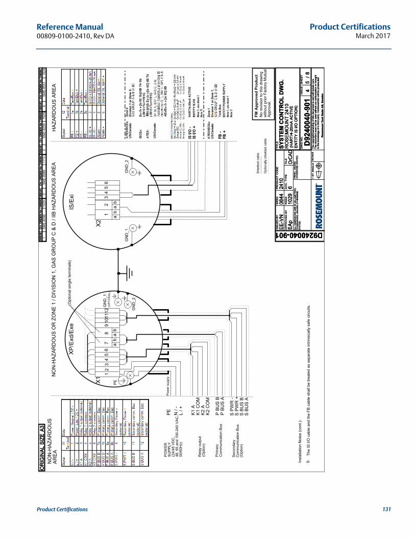
Product CertificationsMarch 2017
Reference Manual 00809-0100-2410, Rev DA
1SM
E-60
96
No
revi
sion
to th
is d
raw
ing
with
out p
rior F
acto
ry M
utua
lAp
prov
al.
FM A
ppro
ved
Pro
duct
Shie
lded
cab
le
Opt
iona
lly s
hiel
ded
cabl
e
1029
L / +
N /
-
K1 C
OM
K2 C
OM
P BU
S B
P BU
S A
PE
ab
ab
X23
45
6
GN
D_1
GN
D_2
IS/E
xi
POW
ERSU
PPLY
(24/
48 V
DC
,48
, 65
and
100-
240
VAC
,50
/60H
z)
Rel
ay o
utpu
t(O
ptio
n)
Prim
ary
Com
mun
icat
ion
Bus
2SM
E-69
8911
13
K1 A
K2 A
Pow
er s
uppl
y
12
NO
N-H
AZAR
DO
US
OR
ZO
NE
1 / D
IVIS
ION
1, G
AS G
RO
UP
C &
D /
IIB H
AZAR
DO
US
AREA
HAZ
ARD
OU
S AR
EAN
ON
-HAZ
ARD
OU
SAR
EA
1 2
a3
b
45
67
8
b
910
1112
a
X1
XP/E
xd/E
xe
(OPT
ION
AL)
PE
GN
D_1
GN
D_2
S BU
S A
S PW
R -
S BU
S B
S PW
R +
Seco
ndar
yC
omm
unic
atio
n Bu
s(O
ptio
n)
(Opt
iona
l sin
gle
term
inal
s)
The
IS I/
O c
able
and
the
FB c
able
sha
ll be
trea
ted
as s
epar
ate
intri
nsic
ally
saf
e ci
rcui
ts.
Inst
alla
tion
Not
es (c
ont.)
:
9.
34
SME-
8259
SME-
8531
1525
1629
ISS
UE
D B
Y
AP
PR
OV
ED
BY
WE
EK
WE
EK
PR
OD
UC
T C
OD
E
DO
C.
TY
PE
FIL
E
TIT
LE
DW
G N
O.
ISS
UE
SH
EE
T
SC
AL
E1
ST
AN
GL
ETh
e co
pyrig
ht/o
wne
rshi
p of
this
doc
umen
t is
and
will
rem
ain
ours
.Th
e do
cum
ent m
ust n
ot b
e us
ed w
ithou
t our
aut
horiz
atio
n or
bro
ught
to th
e kn
owle
dge
of a
third
par
ty. C
ontra
vent
ion
will
be p
rose
cute
d.
Ros
emou
nt T
ank
Rad
ar A
B, S
wed
en
ALL
DIM
ENSI
ON
S AR
E IN
MIL
LIM
ETR
ES.
TO
LER
ANC
ES, U
NLE
SS O
THER
WIS
EST
ATED
:
FIN
ISH
, UN
LESS
OTH
ERW
ISE
STAT
ED:
EE-V
N
1029
2410
EAp
6��
���
D9240040-901D
9240
040-
901
0844
SYST
EM C
ON
TRO
L D
WG
.
4/
RO
SE
MO
UN
T 24
10(H
ART/
4-20
mA
ACTI
VEEN
TITY
IS I/
O O
PTIO
N)
58
ISS
UE
CH
. O
RD
ER
No
WE
EK
ISS
UE
CH
. O
RD
ER
No
WE
EK
ISS
UE
CH
. O
RD
ER
No
WE
EK
ISS
UE
CH
. O
RD
ER
No
WE
EK
ISS
UE
CH
. O
RD
ER
No
WE
EK
ISS
UE
CH
. O
RD
ER
No
WE
EK
ISS
UE
CH
. O
RD
ER
No
WE
EK
ISS
UE
CH
. O
RD
ER
No
WE
EK
ISS
UE
CH
. O
RD
ER
No
WE
EK
ISS
UE
CH
. O
RD
ER
No
WE
EK
ISS
UE
CH
. O
RD
ER
No
WE
EK
ISS
UE
CH
. O
RD
ER
No
WE
EK
OR
IGIN
AL S
IZE
A3O
RIG
INAL
SIZ
EA3
OR
IGIN
AL S
IZE
A3
131Product Certifications
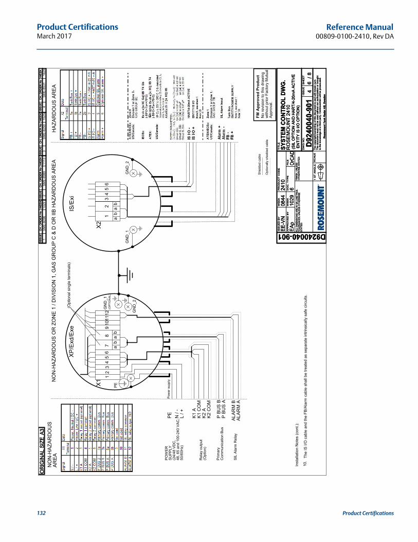
Product CertificationsMarch 2017
Reference Manual00809-0100-2410, Rev DA
1SM
E-60
96
No
revi
sion
to th
is d
raw
ing
with
out p
rior F
acto
ry M
utua
lAp
prov
al.
FM A
ppro
ved
Pro
duct
Shie
lded
cab
le
Opt
iona
lly s
hiel
ded
cabl
e
1029
L / +
N /
-
K1 C
OM
K2 C
OM
P BU
S B
P BU
S A
PE
ab
ab
X23
45
6
GN
D_1
GN
D_2
IS/E
xi
POW
ERSU
PPLY
(24/
48 V
DC
,48
, 65
and
100-
240
VAC
,50
/60H
z)
Rel
ay o
utpu
t(O
ptio
n)
Prim
ary
Com
mun
icat
ion
Bus
2SM
E-69
8911
13
K1 A
K2 A
ALAR
M B
ALAR
M A
Pow
er s
uppl
y
12
SIL
Alar
m R
elay
NO
N-H
AZAR
DO
US
OR
ZO
NE
1 / D
IVIS
ION
1, G
AS G
RO
UP
C &
D O
R II
B H
AZAR
DO
US
AREA
HAZ
ARD
OU
S AR
EAN
ON
-HAZ
ARD
OU
SAR
EA
1 2
a3
b
45
67
8
b
910
1112
a
X1
XP/E
xd/E
xe
(OPT
ION
AL)
PE
GN
D_1
GN
D_2
(Opt
iona
l sin
gle
term
inal
s)
The
IS I/
O c
able
and
the
FB/A
larm
cab
le s
hall
be tr
eate
d as
sep
arat
e in
trins
ical
ly s
afe
circ
uits
.
Inst
alla
tion
Not
es (c
ont.)
:
10.
34
SME-
8259
SME-
8531
1525
1629
ISS
UE
D B
Y
AP
PR
OV
ED
BY
WE
EK
WE
EK
PR
OD
UC
T C
OD
E
DO
C.
TY
PE
FIL
E
TIT
LE
DW
G N
O.
ISS
UE
SH
EE
T
SC
AL
E1
ST
AN
GL
ETh
e co
pyrig
ht/o
wne
rshi
p of
this
doc
umen
t is
and
will
rem
ain
ours
.Th
e do
cum
ent m
ust n
ot b
e us
ed w
ithou
t our
aut
horiz
atio
n or
bro
ught
to th
e kn
owle
dge
of a
third
par
ty. C
ontra
vent
ion
will
be p
rose
cute
d.
Ros
emou
nt T
ank
Rad
ar A
B, S
wed
en
ALL
DIM
ENSI
ON
S AR
E IN
MIL
LIM
ETR
ES.
TO
LER
ANC
ES, U
NLE
SS O
THER
WIS
EST
ATED
:
FIN
ISH
, UN
LESS
OTH
ERW
ISE
STAT
ED:
EE-V
N
1029
2410
EAp
6��
���
D9240040-901D
9240
040-
901
0844
SYST
EM C
ON
TRO
L D
WG
.
4/
RO
SEM
OU
NT
2410
(SIL
OPT
ION
AN
D H
ART/
4-20
mA
ACTI
VEEN
TITY
IS I/
O O
PTIO
N)
68
ISS
UE
CH
. O
RD
ER
No
WE
EK
ISS
UE
CH
. O
RD
ER
No
WE
EK
ISS
UE
CH
. O
RD
ER
No
WE
EK
ISS
UE
CH
. O
RD
ER
No
WE
EK
ISS
UE
CH
. O
RD
ER
No
WE
EK
ISS
UE
CH
. O
RD
ER
No
WE
EK
ISS
UE
CH
. O
RD
ER
No
WE
EK
ISS
UE
CH
. O
RD
ER
No
WE
EK
ISS
UE
CH
. O
RD
ER
No
WE
EK
ISS
UE
CH
. O
RD
ER
No
WE
EK
ISS
UE
CH
. O
RD
ER
No
WE
EK
ISS
UE
CH
. O
RD
ER
No
WE
EK
OR
IGIN
AL S
IZE
A3O
RIG
INAL
SIZ
EA3
OR
IGIN
AL S
IZE
A3
132 Product Certifications
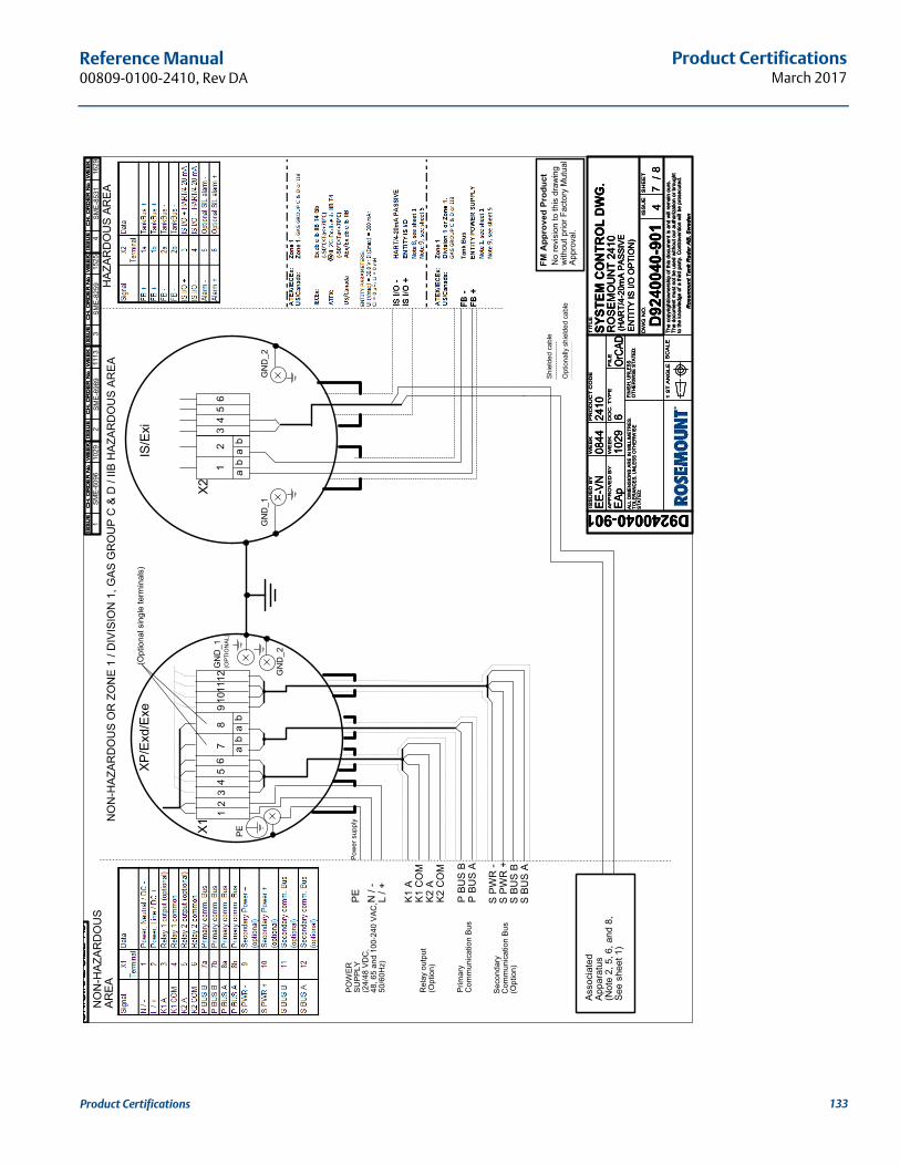
Product CertificationsMarch 2017
Reference Manual 00809-0100-2410, Rev DA
1SM
E-60
96
No
revi
sion
to th
is d
raw
ing
with
out p
rior F
acto
ry M
utua
lAp
prov
al.
FM A
ppro
ved
Pro
duct
Shie
lded
cab
le
Opt
iona
lly s
hiel
ded
cabl
e
1029
L / +
N /
-
K1 C
OM
K2 C
OM
P BU
S B
P BU
S A
PE
ab
ab
X23
45
6
GN
D_1
GN
D_2
IS/E
xi
POW
ERSU
PPLY
(24/
48 V
DC
,48
, 65
and
100-
240
VAC
,50
/60H
z)
Rel
ay o
utpu
t(O
ptio
n)
Prim
ary
Com
mun
icat
ion
Bus
2SM
E-69
8911
13
K1 A
K2 A
Pow
er s
uppl
y
12
NO
N-H
AZAR
DO
US
OR
ZO
NE
1 / D
IVIS
ION
1, G
AS G
RO
UP
C &
D /
IIB H
AZAR
DO
US
AREA
HAZ
ARD
OU
S AR
EAN
ON
-HAZ
ARD
OU
SAR
EA
1 2
a3
b
45
67
8
b
910
1112
a
X1
XP/E
xd/E
xe
(OPT
ION
AL)
PE
GN
D_1
GN
D_2
S BU
S A
S PW
R -
S BU
S B
S PW
R +
Seco
ndar
yC
omm
unic
atio
n Bu
s(O
ptio
n)
(Opt
iona
l sin
gle
term
inal
s)
34
SME-
8259
SME-
8531
1525
1629
Asso
ciat
edAp
para
tus
(Not
e 2,
5, 6
, and
8,
See
shee
t 1)
ISS
UE
D B
Y
AP
PR
OV
ED
BY
WE
EK
WE
EK
PR
OD
UC
T C
OD
E
DO
C.
TY
PE
FIL
E
TIT
LE
DW
G N
O.
ISS
UE
SH
EE
T
SC
AL
E1
ST
AN
GL
ETh
e co
pyrig
ht/o
wne
rshi
p of
this
doc
umen
t is
and
will
rem
ain
ours
.Th
e do
cum
ent m
ust n
ot b
e us
ed w
ithou
t our
aut
horiz
atio
n or
bro
ught
to th
e kn
owle
dge
of a
third
par
ty. C
ontra
vent
ion
will
be p
rose
cute
d.
Ros
emou
nt T
ank
Rad
ar A
B, S
wed
en
ALL
DIM
ENSI
ON
S AR
E IN
MIL
LIM
ETR
ES.
TO
LER
ANC
ES, U
NLE
SS O
THER
WIS
EST
ATED
:
FIN
ISH
, UN
LESS
OTH
ERW
ISE
STAT
ED:
EE-V
N
1029
2410
EAp
6��
���
D9240040-901D
9240
040-
901
0844
SYST
EM C
ON
TRO
L D
WG
.
4/
RO
SE
MO
UN
T 24
10(H
ART/
4-20
mA
PASS
IVE
ENTI
TY IS
I/O
OPT
ION
)
78
ISS
UE
CH
. O
RD
ER
No
WE
EK
ISS
UE
CH
. O
RD
ER
No
WE
EK
ISS
UE
CH
. O
RD
ER
No
WE
EK
ISS
UE
CH
. O
RD
ER
No
WE
EK
ISS
UE
CH
. O
RD
ER
No
WE
EK
ISS
UE
CH
. O
RD
ER
No
WE
EK
ISS
UE
CH
. O
RD
ER
No
WE
EK
ISS
UE
CH
. O
RD
ER
No
WE
EK
ISS
UE
CH
. O
RD
ER
No
WE
EK
ISS
UE
CH
. O
RD
ER
No
WE
EK
ISS
UE
CH
. O
RD
ER
No
WE
EK
ISS
UE
CH
. O
RD
ER
No
WE
EK
OR
IGIN
AL S
IZE
A3O
RIG
INAL
SIZ
EA3
OR
IGIN
AL S
IZE
A3
133Product Certifications
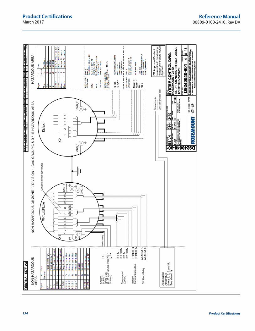
Product CertificationsMarch 2017
Reference Manual00809-0100-2410, Rev DA
1SM
E-60
96
No
revi
sion
to th
is d
raw
ing
with
out p
rior F
acto
ry M
utua
lAp
prov
al.
FM A
ppro
ved
Pro
duct
Shie
lded
cab
le
Opt
iona
lly s
hiel
ded
cabl
e
1029
L / +
N /
-
K1 C
OM
K2 C
OM
P BU
S B
P BU
S A
PE
(Opt
iona
l sin
gle
term
inal
s)
ab
ab
X23
45
6
GN
D_1
GN
D_2
IS/E
xi
1
POW
ERSU
PPLY
(24/
48 V
DC
,48
, 65
and
100-
240
VAC
,50
/60H
z)
Rel
ay o
utpu
t(O
ptio
n)
Prim
ary
Com
mun
icat
ion
Bus
2
2SM
E-69
8911
13
a3
K1 A
K2 A
ALAR
M B
b
4
ALAR
M A
56
78
b
910
11
Pow
er s
uppl
y
12
a
12
X1
XP/E
xd/E
xe
(OPT
ION
AL)
SIL
Alar
m R
elay
PE
GN
D_1
NO
N-H
AZAR
DO
US
OR
ZO
NE
1 / D
IVIS
ION
1, G
AS G
RO
UP
C &
D /
IIB H
AZAR
DO
US
AREA
HAZ
ARD
OU
S AR
EA
GN
D_2
NO
N-H
AZAR
DO
US
AREA
3SM
E-82
5915
254
SME-
8531
1629
Asso
ciat
edAp
para
tus
(Not
e 2,
5, 6
and
8,
See
shee
t 1)
ISS
UE
D B
Y
AP
PR
OV
ED
BY
WE
EK
WE
EK
PR
OD
UC
T C
OD
E
DO
C.
TY
PE
FIL
E
TIT
LE
DW
G N
O.
ISS
UE
SH
EE
T
SC
AL
E1
ST
AN
GL
ETh
e co
pyrig
ht/o
wne
rshi
p of
this
doc
umen
t is
and
will
rem
ain
ours
.Th
e do
cum
ent m
ust n
ot b
e us
ed w
ithou
t our
aut
horiz
atio
n or
bro
ught
to th
e kn
owle
dge
of a
third
par
ty. C
ontra
vent
ion
will
be p
rose
cute
d.
Ros
emou
nt T
ank
Rad
ar A
B, S
wed
en
ALL
DIM
ENSI
ON
S AR
E IN
MIL
LIM
ETR
ES.
TO
LER
ANC
ES, U
NLE
SS O
THER
WIS
EST
ATED
:
FIN
ISH
, UN
LESS
OTH
ERW
ISE
STAT
ED:
EE-V
N
1029
2410
EAp
6��
���
D9240040-901D
9240
040-
901
0844
SYST
EM C
ON
TRO
L D
WG
.
4/
RO
SEM
OU
NT
2410
(SIL
OPT
ION
AN
D H
ART/
4-20
mA
PASS
IVE
ENTI
TY IS
I/O
OPT
ION
)
88
ISS
UE
CH
. O
RD
ER
No
WE
EK
ISS
UE
CH
. O
RD
ER
No
WE
EK
ISS
UE
CH
. O
RD
ER
No
WE
EK
ISS
UE
CH
. O
RD
ER
No
WE
EK
ISS
UE
CH
. O
RD
ER
No
WE
EK
ISS
UE
CH
. O
RD
ER
No
WE
EK
ISS
UE
CH
. O
RD
ER
No
WE
EK
ISS
UE
CH
. O
RD
ER
No
WE
EK
ISS
UE
CH
. O
RD
ER
No
WE
EK
ISS
UE
CH
. O
RD
ER
No
WE
EK
ISS
UE
CH
. O
RD
ER
No
WE
EK
ISS
UE
CH
. O
RD
ER
No
WE
EK
OR
IGIN
AL S
IZE
A3O
RIG
INAL
SIZ
EA3
OR
IGIN
AL S
IZE
A3
134 Product Certifications
Advanced ConfigurationMarch 2017
Reference Manual 00809-0100-2410, Rev DA
Appendix C Advanced Configuration
Safety messages . . . . . . . . . . . . . . . . . . . . . . . . . . . . . . . . . . . . . . . . . . . . . . . . . . . . . . . . . . . . . . . . . . page 135Advanced configuration in Winsetup . . . . . . . . . . . . . . . . . . . . . . . . . . . . . . . . . . . . . . . . . . . . . . . . page 137Primary bus . . . . . . . . . . . . . . . . . . . . . . . . . . . . . . . . . . . . . . . . . . . . . . . . . . . . . . . . . . . . . . . . . . . . . . page 138Secondary bus . . . . . . . . . . . . . . . . . . . . . . . . . . . . . . . . . . . . . . . . . . . . . . . . . . . . . . . . . . . . . . . . . . . page 139Relay output . . . . . . . . . . . . . . . . . . . . . . . . . . . . . . . . . . . . . . . . . . . . . . . . . . . . . . . . . . . . . . . . . . . . . page 140Hybrid density calculation . . . . . . . . . . . . . . . . . . . . . . . . . . . . . . . . . . . . . . . . . . . . . . . . . . . . . . . . . page 144Volume configuration . . . . . . . . . . . . . . . . . . . . . . . . . . . . . . . . . . . . . . . . . . . . . . . . . . . . . . . . . . . . . page 148Arithmetic operations . . . . . . . . . . . . . . . . . . . . . . . . . . . . . . . . . . . . . . . . . . . . . . . . . . . . . . . . . . . . . page 153Analog output . . . . . . . . . . . . . . . . . . . . . . . . . . . . . . . . . . . . . . . . . . . . . . . . . . . . . . . . . . . . . . . . . . . . page 156Configuration of analog input / HART® slave device . . . . . . . . . . . . . . . . . . . . . . . . . . . . . . . . . . . page 160
C.1 Safety messagesProcedures and instructions in this section may require special precautions to ensure the safety of the personnel performing the operations. Information that raises potential safety issues is indicated by a
warning symbol ( ). Please refer to the following safety messages before performing an operation preceded by this symbol.
Explosions could result in death or serious injury:
Verify that the operating environment of the transmitter is consistent with the appropriate hazardous locations certifications.
Before connecting a communicator in an explosive atmosphere, make sure the instruments in the loop are installed in accordance with intrinsically safe or non-incendive field wiring practices.
Do not remove the transmitter cover in explosive atmospheres when the circuit is alive.
Failure to follow safe installation and servicing guidelines could result in death or serious injury:
Make sure the transmitter is installed by qualified personnel and in accordance with applicable code of practice.
Use the equipment only as specified in this manual. Failure to do so may impair the protection provided by the equipment.
Do not perform any service other than those contained in this manual unless you are qualified.
Any substitution of non-recognized spare parts may jeopardize safety. Repair, for e.g. substitution of components etc. may also jeopardize safety and is under no circumstances allowed.
To prevent ignition of flammable or combustible atmospheres, disconnect power before servicing.
135Advanced Configuration
Advanced ConfigurationMarch 2017
Reference Manual00809-0100-2410, Rev DA
High voltage that may be present on leads could cause electrical shock:
Avoid contact with leads and terminals.
Make sure the mains power to the Radar Transmitter is off and the lines to any other external power source are disconnected or not powered while wiringthe transmitter.
Probes covered with plastic and/or with plastic discs may generate an ignition-capable level of electrostatic charge under certain extreme conditions. Therefore, when the probe is used in a potentially explosive atmosphere, appropriate measures must be taken to prevent electrostatic discharge.
136 Advanced Configuration
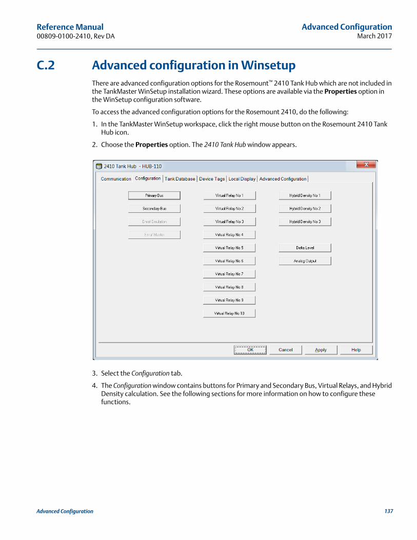
Advanced ConfigurationMarch 2017
Reference Manual 00809-0100-2410, Rev DA
C.2 Advanced configuration in WinsetupThere are advanced configuration options for the Rosemount™ 2410 Tank Hub which are not included in the TankMaster WinSetup installation wizard. These options are available via the Properties option in the WinSetup configuration software.
To access the advanced configuration options for the Rosemount 2410, do the following:
1. In the TankMaster WinSetup workspace, click the right mouse button on the Rosemount 2410 Tank Hub icon.
2. Choose the Properties option. The 2410 Tank Hub window appears.
3. Select the Configuration tab.
4. The Configuration window contains buttons for Primary and Secondary Bus, Virtual Relays, and Hybrid Density calculation. See the following sections for more information on how to configure these functions.
137Advanced Configuration
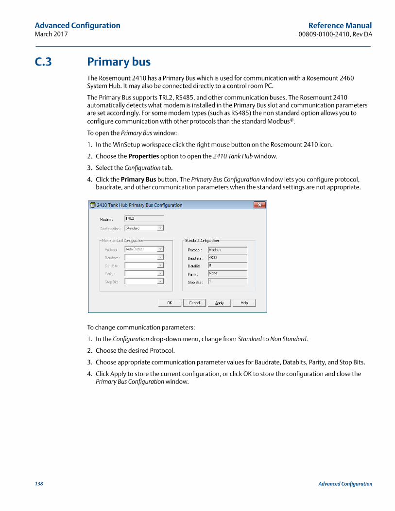
Advanced ConfigurationMarch 2017
Reference Manual00809-0100-2410, Rev DA
C.3 Primary busThe Rosemount 2410 has a Primary Bus which is used for communication with a Rosemount 2460 System Hub. It may also be connected directly to a control room PC.
The Primary Bus supports TRL2, RS485, and other communication buses. The Rosemount 2410 automatically detects what modem is installed in the Primary Bus slot and communication parameters are set accordingly. For some modem types (such as RS485) the non standard option allows you to configure communication with other protocols than the standard Modbus®.
To open the Primary Bus window:
1. In the WinSetup workspace click the right mouse button on the Rosemount 2410 icon.
2. Choose the Properties option to open the 2410 Tank Hub window.
3. Select the Configuration tab.
4. Click the Primary Bus button. The Primary Bus Configuration window lets you configure protocol, baudrate, and other communication parameters when the standard settings are not appropriate.
To change communication parameters:
1. In the Configuration drop-down menu, change from Standard to Non Standard.
2. Choose the desired Protocol.
3. Choose appropriate communication parameter values for Baudrate, Databits, Parity, and Stop Bits.
4. Click Apply to store the current configuration, or click OK to store the configuration and close the Primary Bus Configuration window.
138 Advanced Configuration
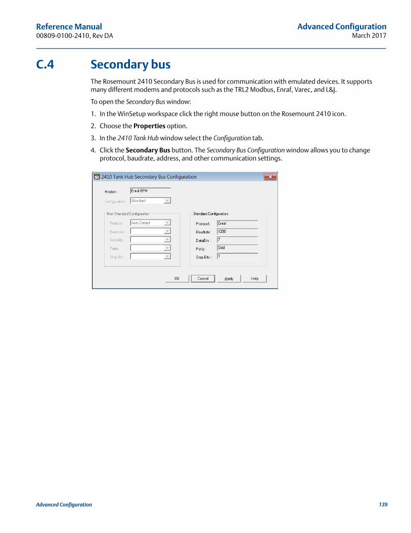
Advanced ConfigurationMarch 2017
Reference Manual 00809-0100-2410, Rev DA
C.4 Secondary busThe Rosemount 2410 Secondary Bus is used for communication with emulated devices. It supports many different modems and protocols such as the TRL2 Modbus, Enraf, Varec, and L&J.
To open the Secondary Bus window:
1. In the WinSetup workspace click the right mouse button on the Rosemount 2410 icon.
2. Choose the Properties option.
3. In the 2410 Tank Hub window select the Configuration tab.
4. Click the Secondary Bus button. The Secondary Bus Configuration window allows you to change protocol, baudrate, address, and other communication settings.
139Advanced Configuration
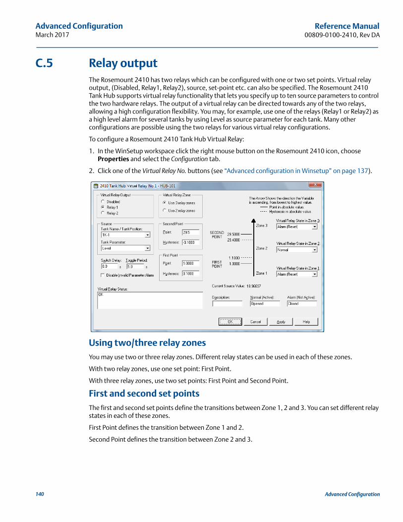
Advanced ConfigurationMarch 2017
Reference Manual00809-0100-2410, Rev DA
C.5 Relay outputThe Rosemount 2410 has two relays which can be configured with one or two set points. Virtual relay output, (Disabled, Relay1, Relay2), source, set-point etc. can also be specified. The Rosemount 2410 Tank Hub supports virtual relay functionality that lets you specify up to ten source parameters to control the two hardware relays. The output of a virtual relay can be directed towards any of the two relays, allowing a high configuration flexibility. You may, for example, use one of the relays (Relay1 or Relay2) as a high level alarm for several tanks by using Level as source parameter for each tank. Many other configurations are possible using the two relays for various virtual relay configurations.
To configure a Rosemount 2410 Tank Hub Virtual Relay:
1. In the WinSetup workspace click the right mouse button on the Rosemount 2410 icon, choose Properties and select the Configuration tab.
2. Click one of the Virtual Relay No. buttons (see “Advanced configuration in Winsetup” on page 137).
Using two/three relay zonesYou may use two or three relay zones. Different relay states can be used in each of these zones.
With two relay zones, use one set point: First Point.
With three relay zones, use two set points: First Point and Second Point.
First and second set pointsThe first and second set points define the transitions between Zone 1, 2 and 3. You can set different relay states in each of these zones.
First Point defines the transition between Zone 1 and 2.
Second Point defines the transition between Zone 2 and 3.
140 Advanced Configuration
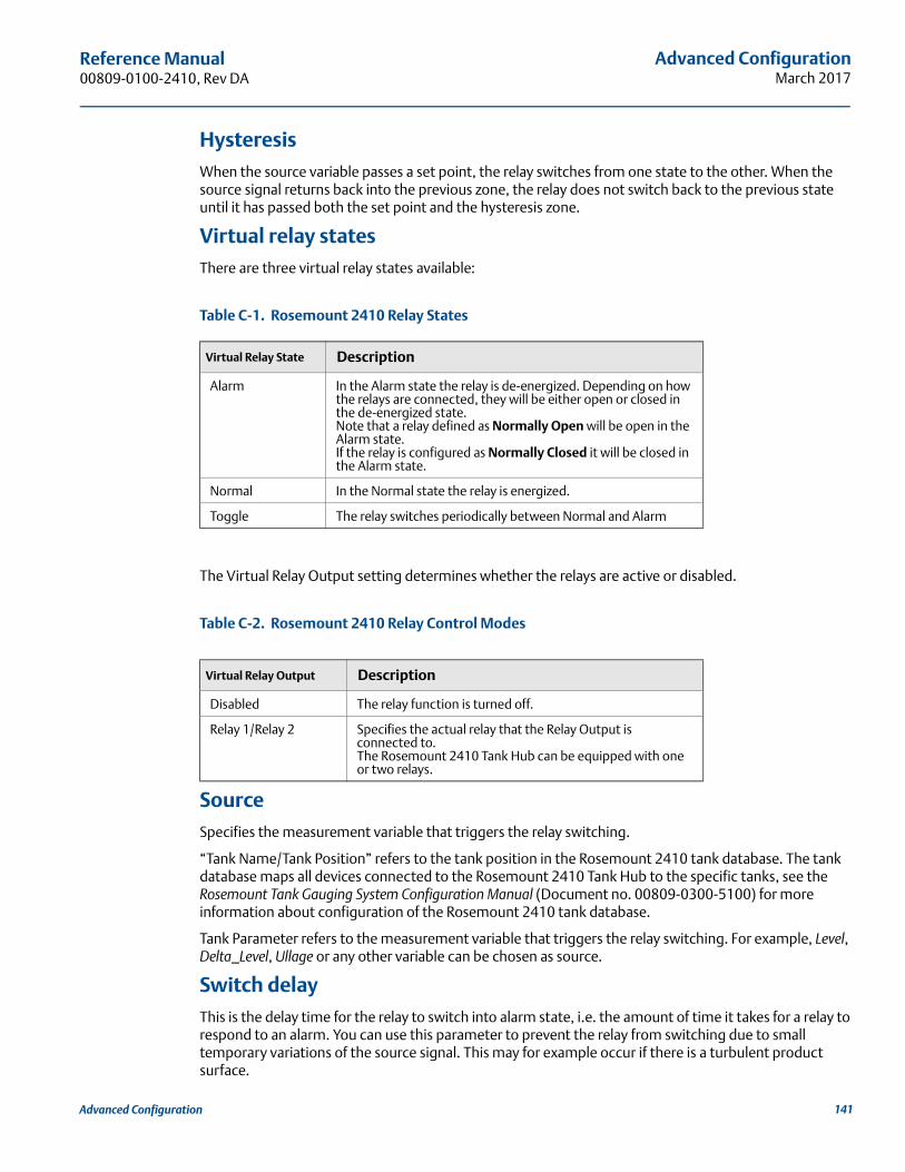
Advanced ConfigurationMarch 2017
Reference Manual 00809-0100-2410, Rev DA
HysteresisWhen the source variable passes a set point, the relay switches from one state to the other. When the source signal returns back into the previous zone, the relay does not switch back to the previous state until it has passed both the set point and the hysteresis zone.
Virtual relay statesThere are three virtual relay states available:
Table C-1. Rosemount 2410 Relay States
The Virtual Relay Output setting determines whether the relays are active or disabled.
Table C-2. Rosemount 2410 Relay Control Modes
SourceSpecifies the measurement variable that triggers the relay switching.
“Tank Name/Tank Position” refers to the tank position in the Rosemount 2410 tank database. The tank database maps all devices connected to the Rosemount 2410 Tank Hub to the specific tanks, see the Rosemount Tank Gauging System Configuration Manual (Document no. 00809-0300-5100) for more information about configuration of the Rosemount 2410 tank database.
Tank Parameter refers to the measurement variable that triggers the relay switching. For example, Level, Delta_Level, Ullage or any other variable can be chosen as source.
Switch delayThis is the delay time for the relay to switch into alarm state, i.e. the amount of time it takes for a relay to respond to an alarm. You can use this parameter to prevent the relay from switching due to small temporary variations of the source signal. This may for example occur if there is a turbulent product surface.
Virtual Relay State Description
Alarm In the Alarm state the relay is de-energized. Depending on how the relays are connected, they will be either open or closed in the de-energized state.Note that a relay defined as Normally Open will be open in the Alarm state.If the relay is configured as Normally Closed it will be closed in the Alarm state.
Normal In the Normal state the relay is energized.
Toggle The relay switches periodically between Normal and Alarm
Virtual Relay Output Description
Disabled The relay function is turned off.
Relay 1/Relay 2 Specifies the actual relay that the Relay Output is connected to. The Rosemount 2410 Tank Hub can be equipped with one or two relays.
141Advanced Configuration
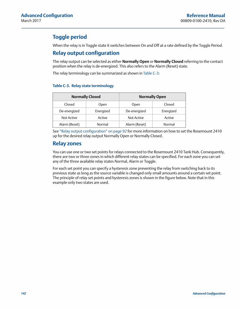
Advanced ConfigurationMarch 2017
Reference Manual00809-0100-2410, Rev DA
Toggle periodWhen the relay is in Toggle state it switches between On and Off at a rate defined by the Toggle Period.
Relay output configurationThe relay output can be selected as either Normally Open or Normally Closed referring to the contact position when the relay is de-energized. This also refers to the Alarm (Reset) state.
The relay terminology can be summarized as shown in Table C-3:
Table C-3. Relay state terminology
See “Relay output configuration” on page 92 for more information on how to set the Rosemount 2410 up for the desired relay output Normally Open or Normally Closed.
Relay zonesYou can use one or two set points for relays connected to the Rosemount 2410 Tank Hub. Consequently, there are two or three zones in which different relay states can be specified. For each zone you can set any of the three available relay states Normal, Alarm or Toggle.
For each set point you can specify a hysteresis zone preventing the relay from switching back to its previous state as long as the source variable is changed only small amounts around a certain set point. The principle of relay set points and hysteresis zones is shown in the figure below. Note that in this example only two states are used.
Normally Closed Normally Open
Closed Open Open Closed
De-energized Energized De-energized Energized
Not Active Active Not Active Active
Alarm (Reset) Normal Alarm (Reset) Normal
142 Advanced Configuration
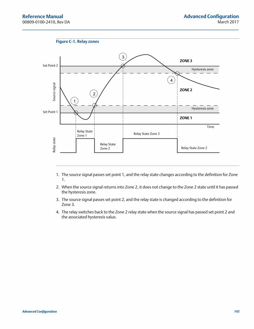
Advanced ConfigurationMarch 2017
Reference Manual 00809-0100-2410, Rev DA
Figure C-1. Relay zones
1. The source signal passes set point 1, and the relay state changes according to the definition for Zone 1.
2. When the source signal returns into Zone 2, it does not change to the Zone 2 state until it has passed the hysteresis zone.
3. The source signal passes set point 2, and the relay state is changed according to the definition for Zone 3.
4. The relay switches back to the Zone 2 relay state when the source signal has passed set point 2 and the associated hysteresis value.
Rela
y st
ate
Time
ZONE 1
ZONE 2
ZONE 3
Sour
ce s
igna
l
1
2
3
4
Relay State Zone 1
Relay State Zone 2
Relay State Zone 3
Relay State Zone 2
Hysteresis zone
Hysteresis zone
Set Point 2
Set Point 1
143Advanced Configuration
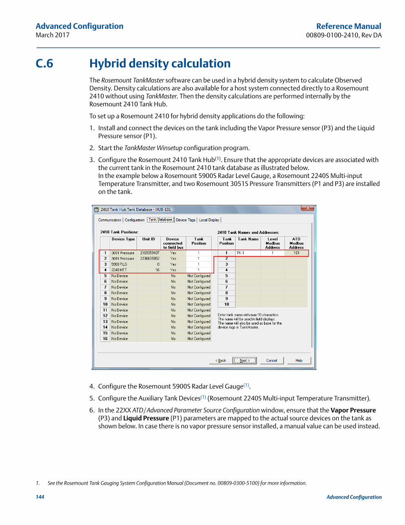
Advanced ConfigurationMarch 2017
Reference Manual00809-0100-2410, Rev DA
C.6 Hybrid density calculationThe Rosemount TankMaster software can be used in a hybrid density system to calculate Observed Density. Density calculations are also available for a host system connected directly to a Rosemount 2410 without using TankMaster. Then the density calculations are performed internally by the Rosemount 2410 Tank Hub.
To set up a Rosemount 2410 for hybrid density applications do the following:
1. Install and connect the devices on the tank including the Vapor Pressure sensor (P3) and the Liquid Pressure sensor (P1).
2. Start the TankMaster Winsetup configuration program.
3. Configure the Rosemount 2410 Tank Hub(1). Ensure that the appropriate devices are associated with the current tank in the Rosemount 2410 tank database as illustrated below.In the example below a Rosemount 5900S Radar Level Gauge, a Rosemount 2240S Multi-input Temperature Transmitter, and two Rosemount 3051S Pressure Transmitters (P1 and P3) are installed on the tank.
4. Configure the Rosemount 5900S Radar Level Gauge(1).
5. Configure the Auxiliary Tank Devices(1) (Rosemount 2240S Multi-input Temperature Transmitter).
6. In the 22XX ATD/ Advanced Parameter Source Configuration window, ensure that the Vapor Pressure (P3) and Liquid Pressure (P1) parameters are mapped to the actual source devices on the tank as shown below. In case there is no vapor pressure sensor installed, a manual value can be used instead.
1. See the Rosemount Tank Gauging System Configuration Manual (Document no. 00809-0300-5100) for more information.
144 Advanced Configuration
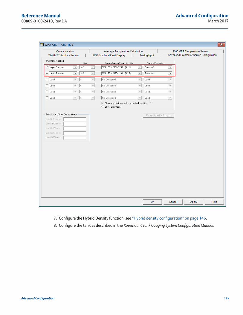
Advanced ConfigurationMarch 2017
Reference Manual 00809-0100-2410, Rev DA
7. Configure the Hybrid Density function, see “Hybrid density configuration” on page 146.
8. Configure the tank as described in the Rosemount Tank Gauging System Configuration Manual.
145Advanced Configuration
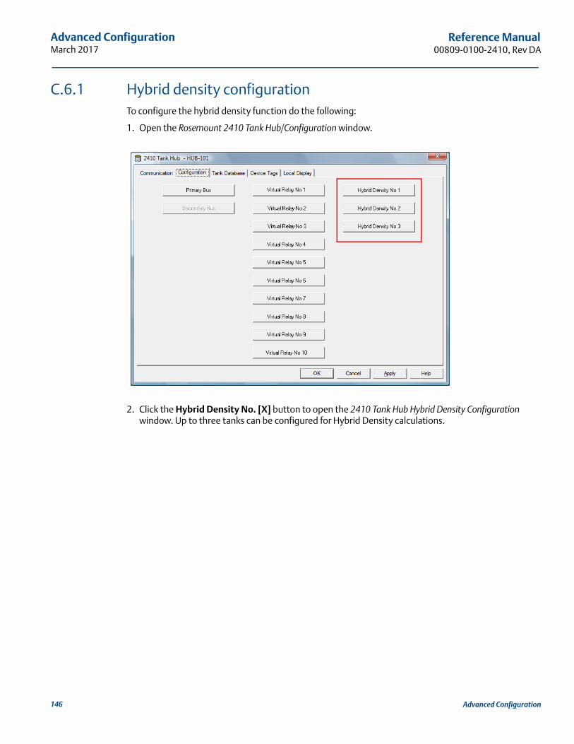
Advanced ConfigurationMarch 2017
Reference Manual00809-0100-2410, Rev DA
C.6.1 Hybrid density configurationTo configure the hybrid density function do the following:
1. Open the Rosemount 2410 Tank Hub/Configuration window.
2. Click the Hybrid Density No. [X] button to open the 2410 Tank Hub Hybrid Density Configuration window. Up to three tanks can be configured for Hybrid Density calculations.
146 Advanced Configuration
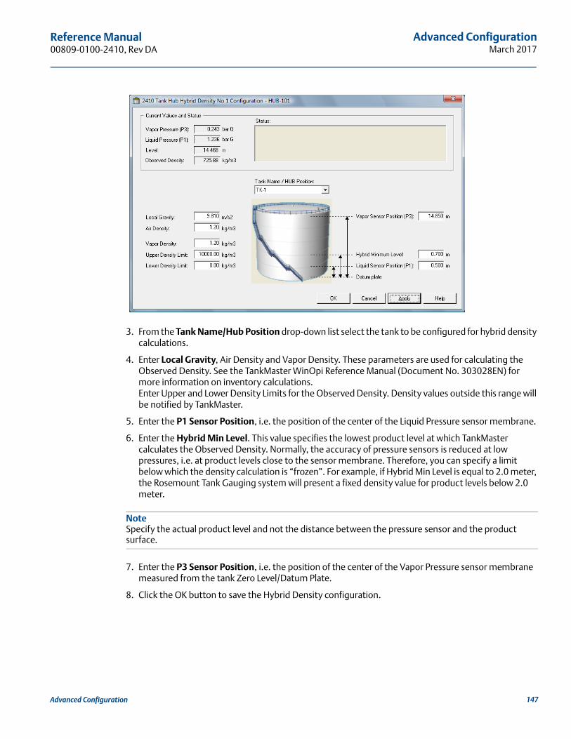
Advanced ConfigurationMarch 2017
Reference Manual 00809-0100-2410, Rev DA
3. From the Tank Name/Hub Position drop-down list select the tank to be configured for hybrid density calculations.
4. Enter Local Gravity, Air Density and Vapor Density. These parameters are used for calculating the Observed Density. See the TankMaster WinOpi Reference Manual (Document No. 303028EN) for more information on inventory calculations. Enter Upper and Lower Density Limits for the Observed Density. Density values outside this range will be notified by TankMaster.
5. Enter the P1 Sensor Position, i.e. the position of the center of the Liquid Pressure sensor membrane.
6. Enter the Hybrid Min Level. This value specifies the lowest product level at which TankMaster calculates the Observed Density. Normally, the accuracy of pressure sensors is reduced at low pressures, i.e. at product levels close to the sensor membrane. Therefore, you can specify a limit below which the density calculation is “frozen”. For example, if Hybrid Min Level is equal to 2.0 meter, the Rosemount Tank Gauging system will present a fixed density value for product levels below 2.0 meter.
NoteSpecify the actual product level and not the distance between the pressure sensor and the product surface.
7. Enter the P3 Sensor Position, i.e. the position of the center of the Vapor Pressure sensor membrane measured from the tank Zero Level/Datum Plate.
8. Click the OK button to save the Hybrid Density configuration.
147Advanced Configuration
Advanced ConfigurationMarch 2017
Reference Manual00809-0100-2410, Rev DA
C.7 Volume configurationTo configure the Rosemount 2410 Tank Hub for volume calculations, choose one of the standard tank shapes, or the strapping table option, see Table C-4 on page 149. Select None if volume calculation is not used. For the standard tanks, a Volume Offset parameter can be specified to be used for a non-zero volume that corresponds to the Zero Level. This may be useful, for example, if you like to include the product volume below the zero level.
Volume calculation is performed by using a predefined tank shape or a strapping table.
NoteFor application software version 1.B5 and older, tank volume calculation has to be enabled in Holding Register 6136 (see “Enable volume calculation in a Rosemount 2410 Tank Hub” on page 152).
One of the following standard tank shapes can be chosen:
Sphere
Horizontal Cylinder
Vertical Cylinder
The following parameters must be entered for a standard tank shape:
Tank diameter
Tank length (for horizontal cylinder)
Volume Offset (use this parameter if you like to include product volume below the zero level)
For application software version 1.B5 and older, tank volume calculation has to be enabled by setting bit 31 "TANK_VOLUME" in Holding Register 6136
C.7.1 Strapping tableThe Strapping Table option should be used when the tank shape deviates significantly from an ideal sphere or cylinder, or when high volume accuracy is required.
The Strapping Table divides the tank into segments. Level values and corresponding volumes are entered starting at the bottom of the tank. These figures can typically be obtained from tank drawings or from a certificate provided by the tank manufacturer.
A maximum of 100 strapping points can be entered. For each level value the corresponding total volume up to the specified level is entered.The volume value is interpolated if the product surface is between two level values in the table.
148 Advanced Configuration
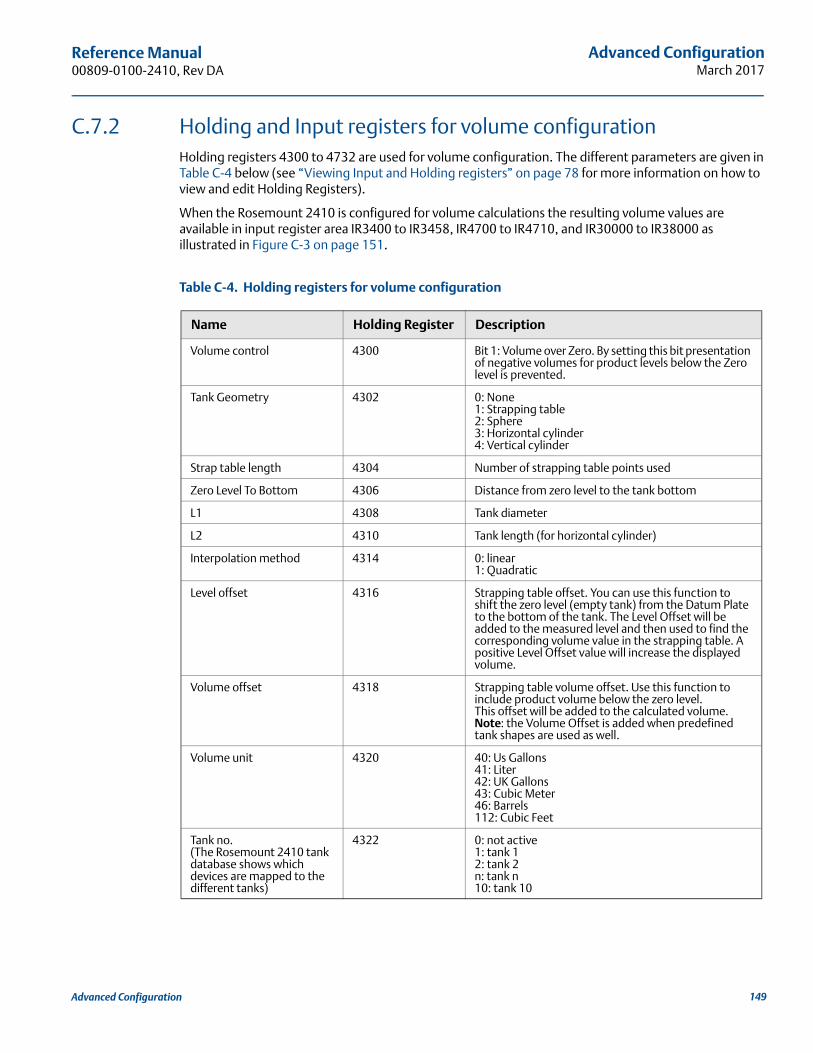
Advanced ConfigurationMarch 2017
Reference Manual 00809-0100-2410, Rev DA
C.7.2 Holding and Input registers for volume configurationHolding registers 4300 to 4732 are used for volume configuration. The different parameters are given in Table C-4 below (see “Viewing Input and Holding registers” on page 78 for more information on how to view and edit Holding Registers).
When the Rosemount 2410 is configured for volume calculations the resulting volume values are available in input register area IR3400 to IR3458, IR4700 to IR4710, and IR30000 to IR38000 as illustrated in Figure C-3 on page 151.
Table C-4. Holding registers for volume configuration
Name Holding Register Description
Volume control 4300 Bit 1: Volume over Zero. By setting this bit presentation of negative volumes for product levels below the Zero level is prevented.
Tank Geometry 4302 0: None1: Strapping table2: Sphere3: Horizontal cylinder4: Vertical cylinder
Strap table length 4304 Number of strapping table points used
Zero Level To Bottom 4306 Distance from zero level to the tank bottom
L1 4308 Tank diameter
L2 4310 Tank length (for horizontal cylinder)
Interpolation method 4314 0: linear1: Quadratic
Level offset 4316 Strapping table offset. You can use this function to shift the zero level (empty tank) from the Datum Plate to the bottom of the tank. The Level Offset will be added to the measured level and then used to find the corresponding volume value in the strapping table. A positive Level Offset value will increase the displayed volume.
Volume offset 4318 Strapping table volume offset. Use this function to include product volume below the zero level.This offset will be added to the calculated volume. Note: the Volume Offset is added when predefined tank shapes are used as well.
Volume unit 4320 40: Us Gallons41: Liter42: UK Gallons43: Cubic Meter46: Barrels112: Cubic Feet
Tank no.(The Rosemount 2410 tank database shows which devices are mapped to the different tanks)
4322 0: not active1: tank 12: tank 2n: tank n10: tank 10
149Advanced Configuration
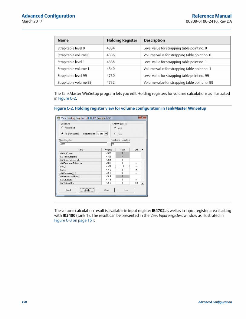
Advanced ConfigurationMarch 2017
Reference Manual00809-0100-2410, Rev DA
The TankMaster WinSetup program lets you edit Holding registers for volume calculations as illustrated in Figure C-2.
Figure C-2. Holding register view for volume configuration in TankMaster WinSetup
The volume calculation result is available in input register IR4702 as well as in input register area starting with IR3400 (tank 1). The result can be presented in the View Input Registers window as illustrated in Figure C-3 on page 151:
Strap table level 0 4334 Level value for strapping table point no. 0
Strap table volume 0 4336 Volume value for strapping table point no. 0
Strap table level 1 4338 Level value for strapping table point no. 1
Strap table volume 1 4340 Volume value for strapping table point no. 1
Strap table level 99 4730 Level value for strapping table point no. 99
Strap table volume 99 4732 Volume value for strapping table point no. 99
Name Holding Register Description
150 Advanced Configuration
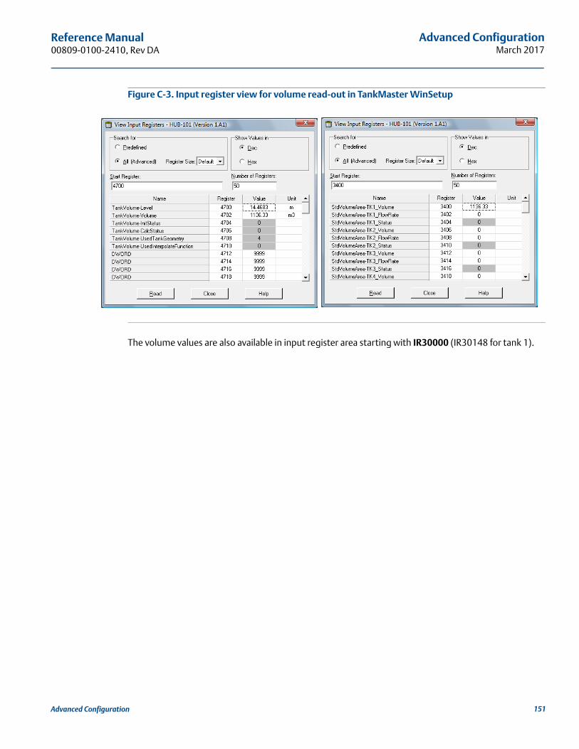
Advanced ConfigurationMarch 2017
Reference Manual 00809-0100-2410, Rev DA
Figure C-3. Input register view for volume read-out in TankMaster WinSetup
The volume values are also available in input register area starting with IR30000 (IR30148 for tank 1).
151Advanced Configuration
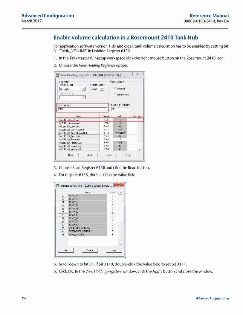
Advanced ConfigurationMarch 2017
Reference Manual00809-0100-2410, Rev DA
Enable volume calculation in a Rosemount 2410 Tank HubFor application software version 1.B5 and older, tank volume calculation has to be enabled by setting bit 31 "TANK_VOLUME" in Holding Register 6136.
1. In the TankMaster Winsetup workspace click the right mouse button on the Rosemount 2410 icon.
2. Choose the View Holding Registers option.
3. Choose Start Register 6136 and click the Read button.
4. For register 6136, double-click the Value field.
5. Scroll down to bit 31. If bit 31=0, double-click the Value field to set bit 31=1.
6. Click OK. In the View Holding Registers window, click the Apply button and close the window.
152 Advanced Configuration
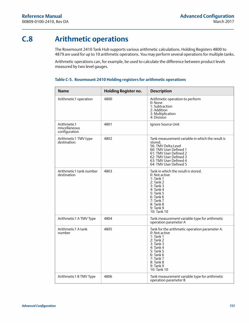
Advanced ConfigurationMarch 2017
Reference Manual 00809-0100-2410, Rev DA
C.8 Arithmetic operationsThe Rosemount 2410 Tank Hub supports various arithmetic calculations. Holding Registers 4800 to 4879 are used for up to 10 arithmetic operations. You may perform several operations for multiple tanks.
Arithmetic operations can, for example, be used to calculate the difference between product levels measured by two level gauges.
Table C-5. Rosemount 2410 Holding registers for arithmetic operations
Name Holding Register no. Description
Arithmetic1 operation 4800 Arithmetic operation to perform0: None1: Subtraction2: Addition3: Multiplication4: Division
Arithmetic1 miscellaneous configuration
4801 Ignore Source Unit
Arithmetic1 TMV type destination
4802 Tank measurement variable in which the result is stored.56: TMV Delta Level60: TMV User Defined 161: TMV User Defined 262: TMV User Defined 363: TMV User Defined 464: TMV User Defined 5
Arithmetic1 tank number destination
4803 Tank in which the result is stored.0: Not active1: Tank 12: Tank 23: Tank 34: Tank 45: Tank 56: Tank 67: Tank 78: Tank 89: Tank 910: Tank 10
Arithmetic1 A TMV Type 4804 Tank measurement variable type for arithmetic operation parameter A
Arithmetic1 A tank number
4805 Tank for the arithmetic operation parameter A.0: Not active1: Tank 12: Tank 23: Tank 34: Tank 45: Tank 56: Tank 67: Tank 78: Tank 89: Tank 910: Tank 10
Arithmetic1 B TMV Type 4806 Tank measurement variable type for arithmetic operation parameter B
153Advanced Configuration
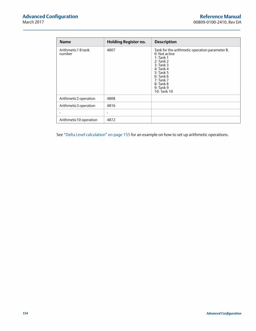
Advanced ConfigurationMarch 2017
Reference Manual00809-0100-2410, Rev DA
See “Delta Level calculation” on page 155 for an example on how to set up arithmetic operations.
Arithmetic1 B tank number
4807 Tank for the arithmetic operation parameter B.0: Not active1: Tank 12: Tank 23: Tank 34: Tank 45: Tank 56: Tank 67: Tank 78: Tank 89: Tank 910: Tank 10
Arithmetic2 operation 4808
Arithmetic3 operation 4816
- -
Arithmetic10 operation 4872
Name Holding Register no. Description
154 Advanced Configuration
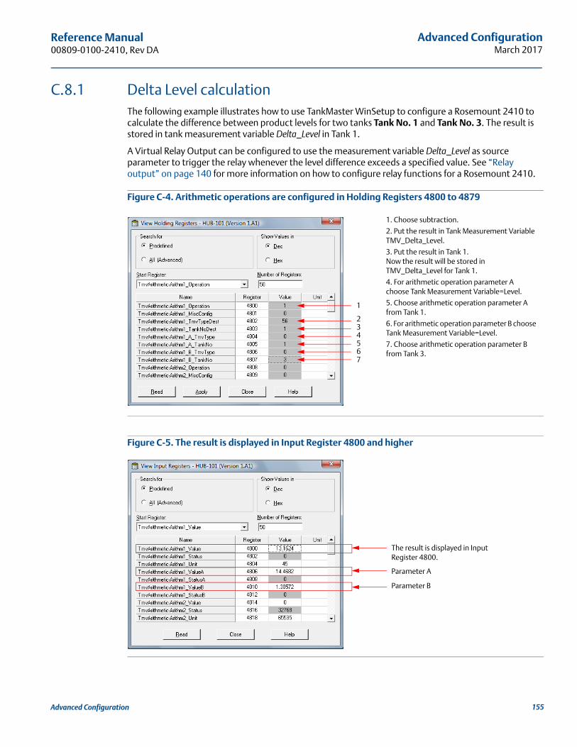
Advanced ConfigurationMarch 2017
Reference Manual 00809-0100-2410, Rev DA
C.8.1 Delta Level calculationThe following example illustrates how to use TankMaster WinSetup to configure a Rosemount 2410 to calculate the difference between product levels for two tanks Tank No. 1 and Tank No. 3. The result is stored in tank measurement variable Delta_Level in Tank 1.
A Virtual Relay Output can be configured to use the measurement variable Delta_Level as source parameter to trigger the relay whenever the level difference exceeds a specified value. See “Relay output” on page 140 for more information on how to configure relay functions for a Rosemount 2410.
Figure C-4. Arithmetic operations are configured in Holding Registers 4800 to 4879
Figure C-5. The result is displayed in Input Register 4800 and higher
1. Choose subtraction.
2. Put the result in Tank Measurement Variable TMV_Delta_Level.
3. Put the result in Tank 1. Now the result will be stored in TMV_Delta_Level for Tank 1.
4. For arithmetic operation parameter A choose Tank Measurement Variable=Level.
5. Choose arithmetic operation parameter A from Tank 1.
6. For arithmetic operation parameter B choose Tank Measurement Variable=Level.
7. Choose arithmetic operation parameter B from Tank 3.
1
23
5
7
4
6
The result is displayed in Input Register 4800.
Parameter A
Parameter B
155Advanced Configuration
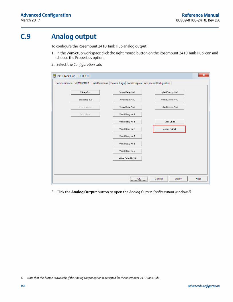
Advanced ConfigurationMarch 2017
Reference Manual00809-0100-2410, Rev DA
C.9 Analog outputTo configure the Rosemount 2410 Tank Hub analog output:
1. In the WinSetup workspace click the right mouse button on the Rosemount 2410 Tank Hub icon and choose the Properties option.
2. Select the Configuration tab:
3. Click the Analog Output button to open the Analog Output Configuration window(1).
1. Note that this button is available if the Analog Output option is activated for the Rosemount 2410 Tank Hub.
156 Advanced Configuration
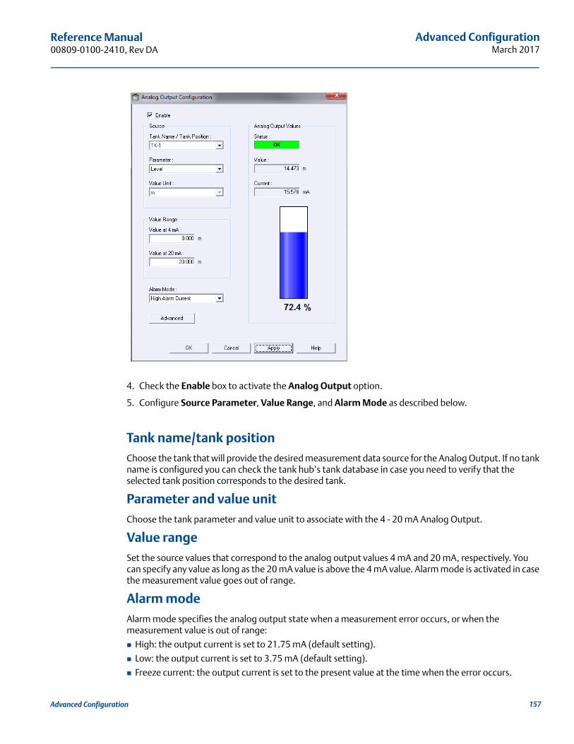
Advanced ConfigurationMarch 2017
Reference Manual 00809-0100-2410, Rev DA
4. Check the Enable box to activate the Analog Output option.
5. Configure Source Parameter, Value Range, and Alarm Mode as described below.
Tank name/tank positionChoose the tank that will provide the desired measurement data source for the Analog Output. If no tank name is configured you can check the tank hub’s tank database in case you need to verify that the selected tank position corresponds to the desired tank.
Parameter and value unitChoose the tank parameter and value unit to associate with the 4 - 20 mA Analog Output.
Value rangeSet the source values that correspond to the analog output values 4 mA and 20 mA, respectively. You can specify any value as long as the 20 mA value is above the 4 mA value. Alarm mode is activated in case the measurement value goes out of range.
Alarm modeAlarm mode specifies the analog output state when a measurement error occurs, or when the measurement value is out of range:
High: the output current is set to 21.75 mA (default setting).
Low: the output current is set to 3.75 mA (default setting).
Freeze current: the output current is set to the present value at the time when the error occurs.
157Advanced Configuration
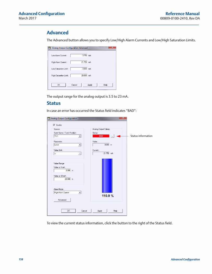
Advanced ConfigurationMarch 2017
Reference Manual00809-0100-2410, Rev DA
AdvancedThe Advanced button allows you to specify Low/High Alarm Currents and Low/High Saturation Limits.
The output range for the analog output is 3.5 to 23 mA.
StatusIn case an error has occurred the Status field indicates “BAD”:
To view the current status information, click the button to the right of the Status field.
Status information
158 Advanced Configuration
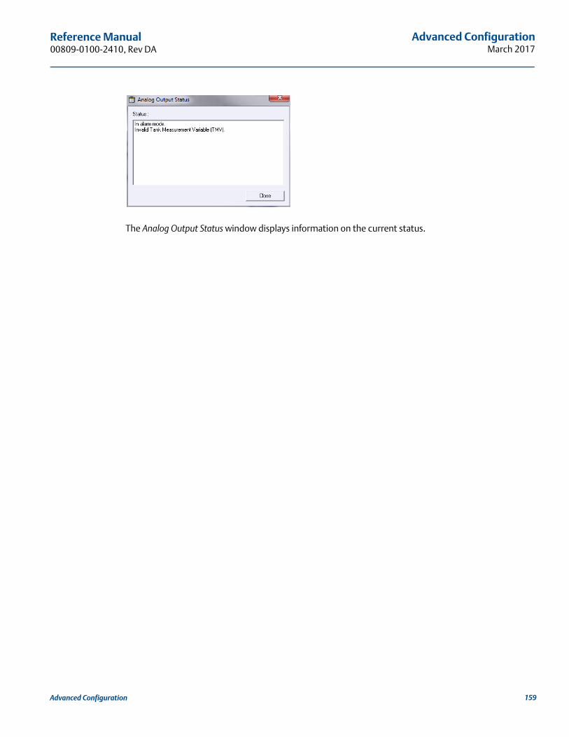
Advanced ConfigurationMarch 2017
Reference Manual 00809-0100-2410, Rev DA
The Analog Output Status window displays information on the current status.
159Advanced Configuration
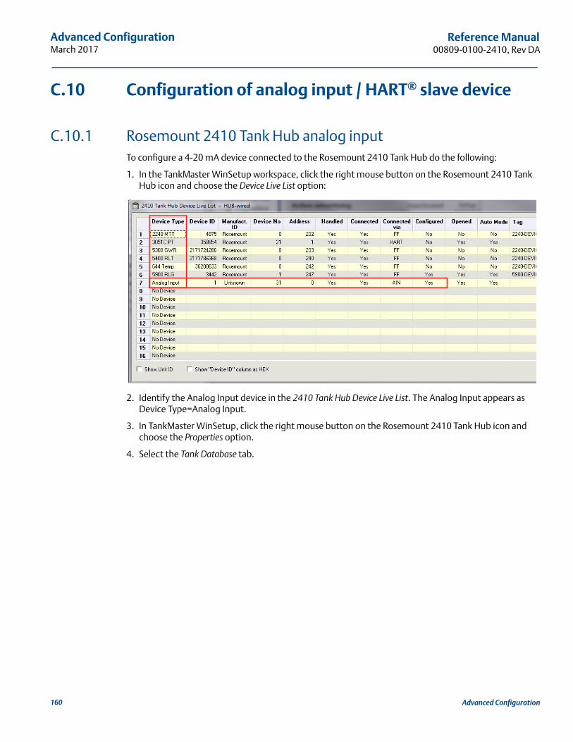
Advanced ConfigurationMarch 2017
Reference Manual00809-0100-2410, Rev DA
C.10 Configuration of analog input / HART® slave device
C.10.1 Rosemount 2410 Tank Hub analog inputTo configure a 4-20 mA device connected to the Rosemount 2410 Tank Hub do the following:
1. In the TankMaster WinSetup workspace, click the right mouse button on the Rosemount 2410 Tank Hub icon and choose the Device Live List option:
2. Identify the Analog Input device in the 2410 Tank Hub Device Live List. The Analog Input appears as Device Type=Analog Input.
3. In TankMaster WinSetup, click the right mouse button on the Rosemount 2410 Tank Hub icon and choose the Properties option.
4. Select the Tank Database tab.
160 Advanced Configuration
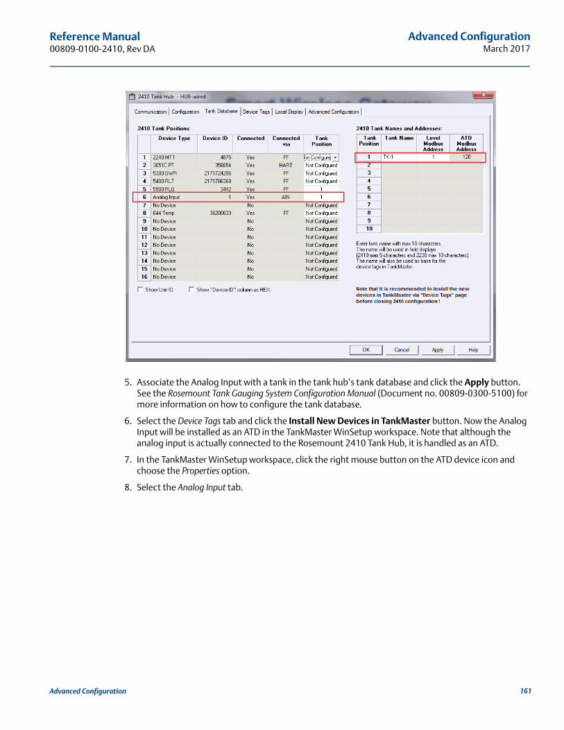
Advanced ConfigurationMarch 2017
Reference Manual 00809-0100-2410, Rev DA
5. Associate the Analog Input with a tank in the tank hub’s tank database and click the Apply button. See the Rosemount Tank Gauging System Configuration Manual (Document no. 00809-0300-5100) for more information on how to configure the tank database.
6. Select the Device Tags tab and click the Install New Devices in TankMaster button. Now the Analog Input will be installed as an ATD in the TankMaster WinSetup workspace. Note that although the analog input is actually connected to the Rosemount 2410 Tank Hub, it is handled as an ATD.
7. In the TankMaster WinSetup workspace, click the right mouse button on the ATD device icon and choose the Properties option.
8. Select the Analog Input tab.
161Advanced Configuration
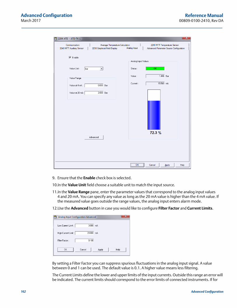
Advanced ConfigurationMarch 2017
Reference Manual00809-0100-2410, Rev DA
9. Ensure that the Enable check box is selected.
10.In the Value Unit field choose a suitable unit to match the input source.
11.In the Value Range pane, enter the parameter values that correspond to the analog input values 4 and 20 mA. You can specify any value as long as the 20 mA value is higher than the 4 mA value. If the measured value goes outside the range values, the analog input enters alarm mode.
12.Use the Advanced button in case you would like to configure Filter Factor and Current Limits.
By setting a Filter Factor you can suppress spurious fluctuations in the analog input signal. A value between 0 and 1 can be used. The default value is 0.1. A higher value means less filtering.
The Current Limits define the lower and upper limits of the input currents. Outside this range an error will be indicated. The current limits should correspond to the error limits of connected instruments. If for
162 Advanced Configuration
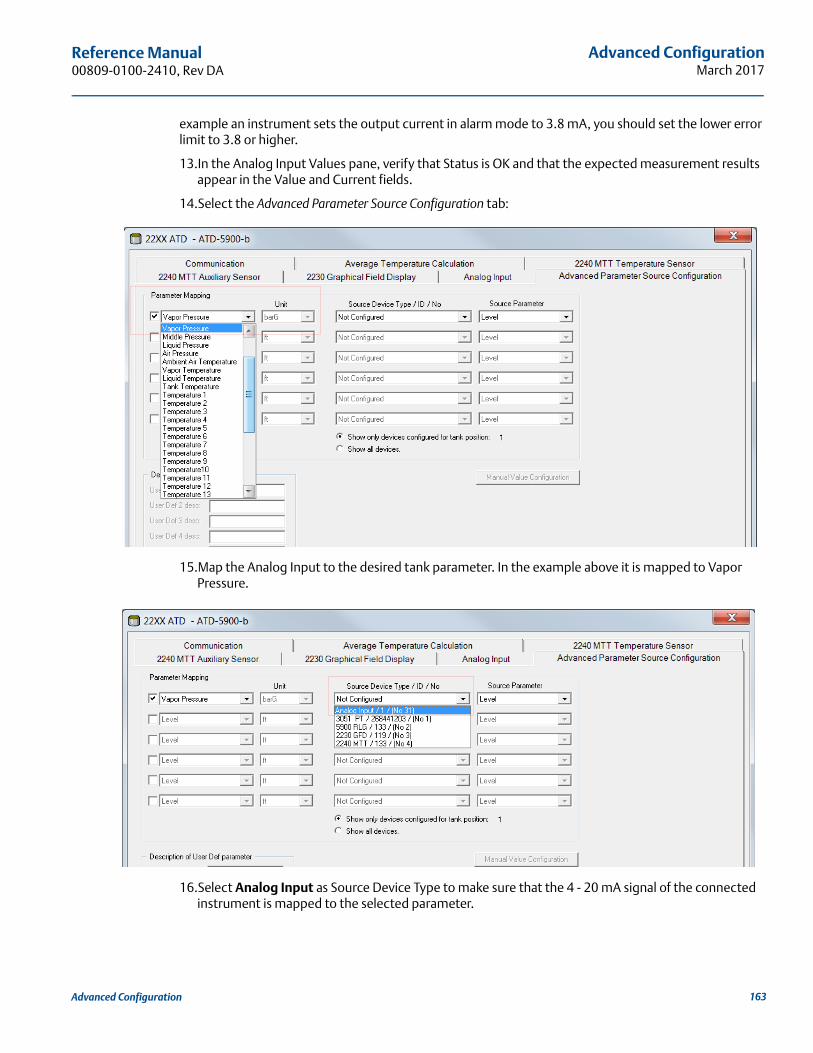
Advanced ConfigurationMarch 2017
Reference Manual 00809-0100-2410, Rev DA
example an instrument sets the output current in alarm mode to 3.8 mA, you should set the lower error limit to 3.8 or higher.
13.In the Analog Input Values pane, verify that Status is OK and that the expected measurement results appear in the Value and Current fields.
14.Select the Advanced Parameter Source Configuration tab:
15.Map the Analog Input to the desired tank parameter. In the example above it is mapped to Vapor Pressure.
16.Select Analog Input as Source Device Type to make sure that the 4 - 20 mA signal of the connected instrument is mapped to the selected parameter.
163Advanced Configuration
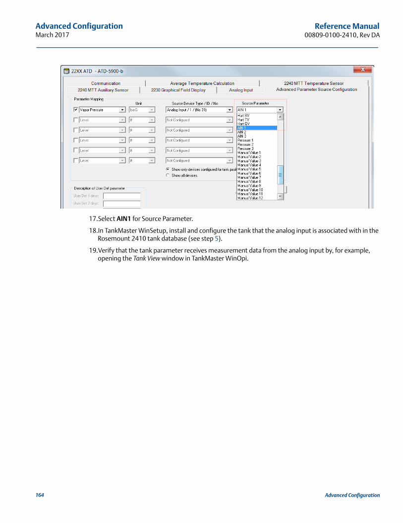
Advanced ConfigurationMarch 2017
Reference Manual00809-0100-2410, Rev DA
17.Select AIN1 for Source Parameter.
18.In TankMaster WinSetup, install and configure the tank that the analog input is associated with in the Rosemount 2410 tank database (see step 5).
19.Verify that the tank parameter receives measurement data from the analog input by, for example, opening the Tank View window in TankMaster WinOpi.
164 Advanced Configuration
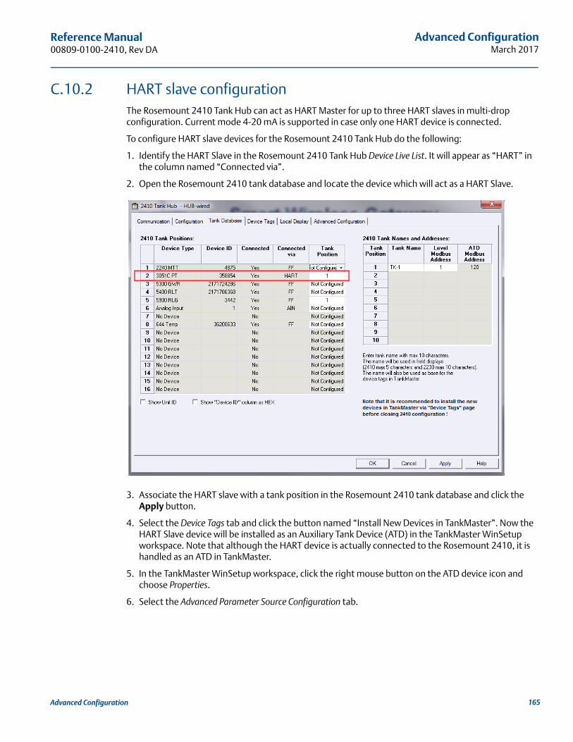
Advanced ConfigurationMarch 2017
Reference Manual 00809-0100-2410, Rev DA
C.10.2 HART slave configurationThe Rosemount 2410 Tank Hub can act as HART Master for up to three HART slaves in multi-drop configuration. Current mode 4-20 mA is supported in case only one HART device is connected.
To configure HART slave devices for the Rosemount 2410 Tank Hub do the following:
1. Identify the HART Slave in the Rosemount 2410 Tank Hub Device Live List. It will appear as “HART” in the column named “Connected via”.
2. Open the Rosemount 2410 tank database and locate the device which will act as a HART Slave.
3. Associate the HART slave with a tank position in the Rosemount 2410 tank database and click the Apply button.
4. Select the Device Tags tab and click the button named “Install New Devices in TankMaster”. Now the HART Slave device will be installed as an Auxiliary Tank Device (ATD) in the TankMaster WinSetup workspace. Note that although the HART device is actually connected to the Rosemount 2410, it is handled as an ATD in TankMaster.
5. In the TankMaster WinSetup workspace, click the right mouse button on the ATD device icon and choose Properties.
6. Select the Advanced Parameter Source Configuration tab.
165Advanced Configuration
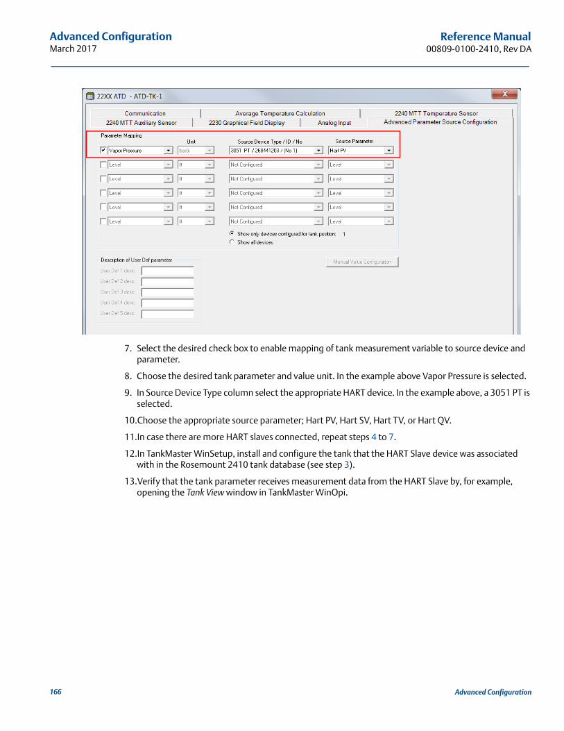
Advanced ConfigurationMarch 2017
Reference Manual00809-0100-2410, Rev DA
7. Select the desired check box to enable mapping of tank measurement variable to source device and parameter.
8. Choose the desired tank parameter and value unit. In the example above Vapor Pressure is selected.
9. In Source Device Type column select the appropriate HART device. In the example above, a 3051 PT is selected.
10.Choose the appropriate source parameter; Hart PV, Hart SV, Hart TV, or Hart QV.
11.In case there are more HART slaves connected, repeat steps 4 to 7.
12.In TankMaster WinSetup, install and configure the tank that the HART Slave device was associated with in the Rosemount 2410 tank database (see step 3).
13.Verify that the tank parameter receives measurement data from the HART Slave by, for example, opening the Tank View window in TankMaster WinOpi.
166 Advanced Configuration
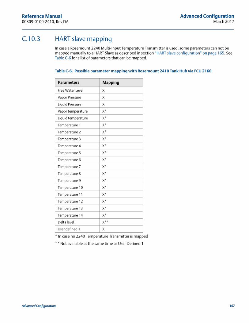
Advanced ConfigurationMarch 2017
Reference Manual 00809-0100-2410, Rev DA
C.10.3 HART slave mappingIn case a Rosemount 2240 Multi-Input Temperature Transmitter is used, some parameters can not be mapped manually to a HART Slave as described in section “HART slave configuration” on page 165. See Table C-6 for a list of parameters that can be mapped.
Table C-6. Possible parameter mapping with Rosemount 2410 Tank Hub via FCU 2160.
* In case no 2240 Temperature Transmitter is mapped
** Not available at the same time as User Defined 1
Parameters Mapping
Free Water Level X
Vapor Pressure X
Liquid Pressure X
Vapor temperature X*
Liquid temperature X*
Temperature 1 X*
Temperature 2 X*
Temperature 3 X*
Temperature 4 X*
Temperature 5 X*
Temperature 6 X*
Temperature 7 X*
Temperature 8 X*
Temperature 9 X*
Temperature 10 X*
Temperature 11 X*
Temperature 12 X*
Temperature 13 X*
Temperature 14 X*
Delta level X**
User defined 1 X
167Advanced Configuration
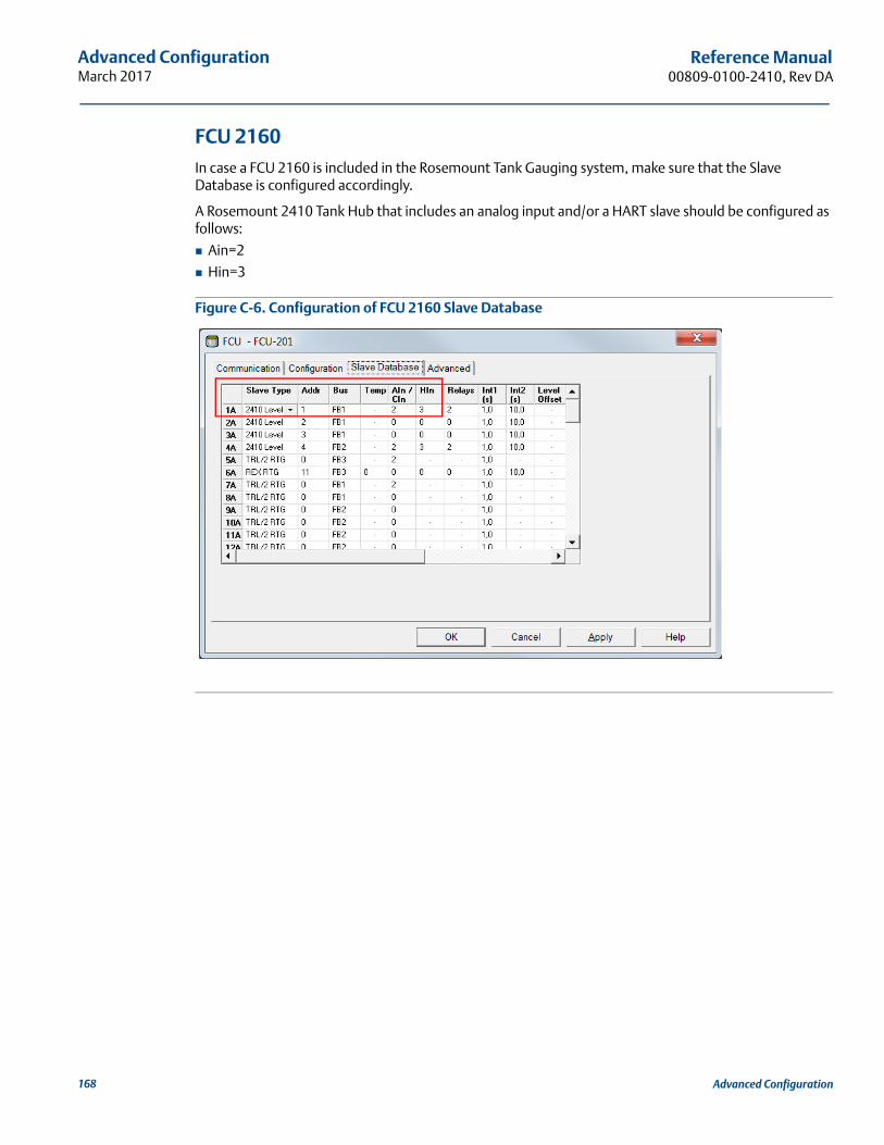
Advanced ConfigurationMarch 2017
Reference Manual00809-0100-2410, Rev DA
FCU 2160In case a FCU 2160 is included in the Rosemount Tank Gauging system, make sure that the Slave Database is configured accordingly.
A Rosemount 2410 Tank Hub that includes an analog input and/or a HART slave should be configured as follows:
Ain=2
Hin=3
Figure C-6. Configuration of FCU 2160 Slave Database
168 Advanced Configuration
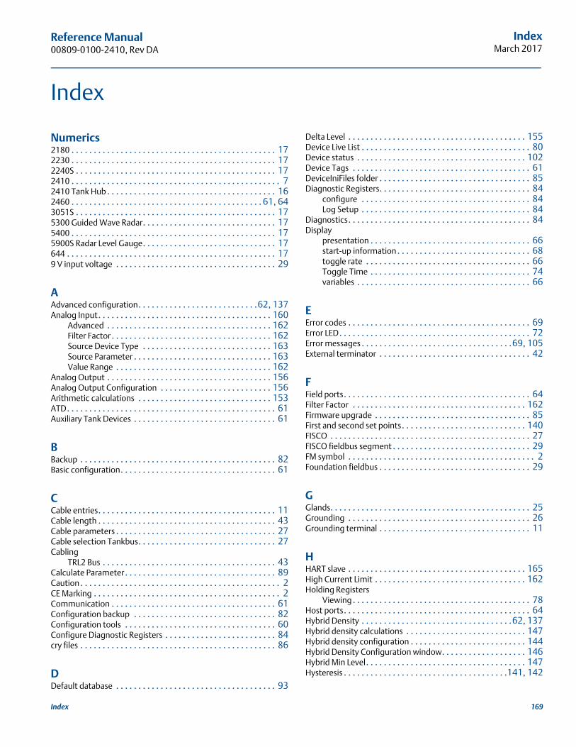
Reference Manual 00809-0100-2410, Rev DA
IndexMarch 2017
Index
Numerics2180 . . . . . . . . . . . . . . . . . . . . . . . . . . . . . . . . . . . . . . . . . . . . . . 172230 . . . . . . . . . . . . . . . . . . . . . . . . . . . . . . . . . . . . . . . . . . . . . . 172240S . . . . . . . . . . . . . . . . . . . . . . . . . . . . . . . . . . . . . . . . . . . . . 172410 . . . . . . . . . . . . . . . . . . . . . . . . . . . . . . . . . . . . . . . . . . . . . . . 72410 Tank Hub . . . . . . . . . . . . . . . . . . . . . . . . . . . . . . . . . . . . . . 162460 . . . . . . . . . . . . . . . . . . . . . . . . . . . . . . . . . . . . . . . . . . . 61, 643051S . . . . . . . . . . . . . . . . . . . . . . . . . . . . . . . . . . . . . . . . . . . . . 175300 Guided Wave Radar. . . . . . . . . . . . . . . . . . . . . . . . . . . . . . 175400 . . . . . . . . . . . . . . . . . . . . . . . . . . . . . . . . . . . . . . . . . . . . . . 175900S Radar Level Gauge. . . . . . . . . . . . . . . . . . . . . . . . . . . . . . 17644 . . . . . . . . . . . . . . . . . . . . . . . . . . . . . . . . . . . . . . . . . . . . . . . 179 V input voltage . . . . . . . . . . . . . . . . . . . . . . . . . . . . . . . . . . . . 29
AAdvanced configuration. . . . . . . . . . . . . . . . . . . . . . . . . . .62, 137Analog Input. . . . . . . . . . . . . . . . . . . . . . . . . . . . . . . . . . . . . . . 160
Advanced . . . . . . . . . . . . . . . . . . . . . . . . . . . . . . . . . . . . . 162Filter Factor . . . . . . . . . . . . . . . . . . . . . . . . . . . . . . . . . . . . 162Source Device Type . . . . . . . . . . . . . . . . . . . . . . . . . . . . . 163Source Parameter . . . . . . . . . . . . . . . . . . . . . . . . . . . . . . . 163Value Range . . . . . . . . . . . . . . . . . . . . . . . . . . . . . . . . . . . 162
Analog Output . . . . . . . . . . . . . . . . . . . . . . . . . . . . . . . . . . . . . 156Analog Output Configuration . . . . . . . . . . . . . . . . . . . . . . . . . 156Arithmetic calculations . . . . . . . . . . . . . . . . . . . . . . . . . . . . . . 153ATD. . . . . . . . . . . . . . . . . . . . . . . . . . . . . . . . . . . . . . . . . . . . . . . 61Auxiliary Tank Devices . . . . . . . . . . . . . . . . . . . . . . . . . . . . . . . . 61
BBackup . . . . . . . . . . . . . . . . . . . . . . . . . . . . . . . . . . . . . . . . . . . . 82Basic configuration. . . . . . . . . . . . . . . . . . . . . . . . . . . . . . . . . . . 61
CCable entries. . . . . . . . . . . . . . . . . . . . . . . . . . . . . . . . . . . . . . . . 11Cable length . . . . . . . . . . . . . . . . . . . . . . . . . . . . . . . . . . . . . . . . 43Cable parameters . . . . . . . . . . . . . . . . . . . . . . . . . . . . . . . . . . . . 27Cable selection Tankbus. . . . . . . . . . . . . . . . . . . . . . . . . . . . . . . 27Cabling
TRL2 Bus . . . . . . . . . . . . . . . . . . . . . . . . . . . . . . . . . . . . . . . 43Calculate Parameter. . . . . . . . . . . . . . . . . . . . . . . . . . . . . . . . . . 89Caution . . . . . . . . . . . . . . . . . . . . . . . . . . . . . . . . . . . . . . . . . . . . . 2CE Marking . . . . . . . . . . . . . . . . . . . . . . . . . . . . . . . . . . . . . . . . . . 2Communication . . . . . . . . . . . . . . . . . . . . . . . . . . . . . . . . . . . . . 61Configuration backup . . . . . . . . . . . . . . . . . . . . . . . . . . . . . . . . 82Configuration tools . . . . . . . . . . . . . . . . . . . . . . . . . . . . . . . . . . 60Configure Diagnostic Registers . . . . . . . . . . . . . . . . . . . . . . . . . 84cry files . . . . . . . . . . . . . . . . . . . . . . . . . . . . . . . . . . . . . . . . . . . . 86
DDefault database . . . . . . . . . . . . . . . . . . . . . . . . . . . . . . . . . . . . 93
Delta Level . . . . . . . . . . . . . . . . . . . . . . . . . . . . . . . . . . . . . . . . 155Device Live List . . . . . . . . . . . . . . . . . . . . . . . . . . . . . . . . . . . . . . 80Device status . . . . . . . . . . . . . . . . . . . . . . . . . . . . . . . . . . . . . . 102Device Tags . . . . . . . . . . . . . . . . . . . . . . . . . . . . . . . . . . . . . . . . 61DeviceIniFiles folder . . . . . . . . . . . . . . . . . . . . . . . . . . . . . . . . . . 85Diagnostic Registers. . . . . . . . . . . . . . . . . . . . . . . . . . . . . . . . . . 84
configure . . . . . . . . . . . . . . . . . . . . . . . . . . . . . . . . . . . . . . 84Log Setup . . . . . . . . . . . . . . . . . . . . . . . . . . . . . . . . . . . . . . 84
Diagnostics. . . . . . . . . . . . . . . . . . . . . . . . . . . . . . . . . . . . . . . . . 84Display
presentation . . . . . . . . . . . . . . . . . . . . . . . . . . . . . . . . . . . . 66start-up information . . . . . . . . . . . . . . . . . . . . . . . . . . . . . . 68toggle rate . . . . . . . . . . . . . . . . . . . . . . . . . . . . . . . . . . . . . 66Toggle Time . . . . . . . . . . . . . . . . . . . . . . . . . . . . . . . . . . . . 74variables . . . . . . . . . . . . . . . . . . . . . . . . . . . . . . . . . . . . . . . 66
EError codes . . . . . . . . . . . . . . . . . . . . . . . . . . . . . . . . . . . . . . . . . 69Error LED. . . . . . . . . . . . . . . . . . . . . . . . . . . . . . . . . . . . . . . . . . . 72Error messages . . . . . . . . . . . . . . . . . . . . . . . . . . . . . . . . . .69, 105External terminator . . . . . . . . . . . . . . . . . . . . . . . . . . . . . . . . . . 42
FField ports. . . . . . . . . . . . . . . . . . . . . . . . . . . . . . . . . . . . . . . . . . 64Filter Factor . . . . . . . . . . . . . . . . . . . . . . . . . . . . . . . . . . . . . . . 162Firmware upgrade . . . . . . . . . . . . . . . . . . . . . . . . . . . . . . . . . . . 85First and second set points. . . . . . . . . . . . . . . . . . . . . . . . . . . . 140FISCO . . . . . . . . . . . . . . . . . . . . . . . . . . . . . . . . . . . . . . . . . . . . . 27FISCO fieldbus segment . . . . . . . . . . . . . . . . . . . . . . . . . . . . . . . 29FM symbol . . . . . . . . . . . . . . . . . . . . . . . . . . . . . . . . . . . . . . . . . . 2Foundation fieldbus . . . . . . . . . . . . . . . . . . . . . . . . . . . . . . . . . . 29
GGlands. . . . . . . . . . . . . . . . . . . . . . . . . . . . . . . . . . . . . . . . . . . . . 25Grounding . . . . . . . . . . . . . . . . . . . . . . . . . . . . . . . . . . . . . . . . . 26Grounding terminal . . . . . . . . . . . . . . . . . . . . . . . . . . . . . . . . . . 11
HHART slave . . . . . . . . . . . . . . . . . . . . . . . . . . . . . . . . . . . . . . . . 165High Current Limit . . . . . . . . . . . . . . . . . . . . . . . . . . . . . . . . . . 162Holding Registers
Viewing . . . . . . . . . . . . . . . . . . . . . . . . . . . . . . . . . . . . . . . . 78Host ports. . . . . . . . . . . . . . . . . . . . . . . . . . . . . . . . . . . . . . . . . . 64Hybrid Density . . . . . . . . . . . . . . . . . . . . . . . . . . . . . . . . . .62, 137Hybrid density calculations . . . . . . . . . . . . . . . . . . . . . . . . . . . 147Hybrid density configuration . . . . . . . . . . . . . . . . . . . . . . . . . . 144Hybrid Density Configuration window. . . . . . . . . . . . . . . . . . . 146Hybrid Min Level. . . . . . . . . . . . . . . . . . . . . . . . . . . . . . . . . . . . 147Hysteresis . . . . . . . . . . . . . . . . . . . . . . . . . . . . . . . . . . . . .141, 142
169Index
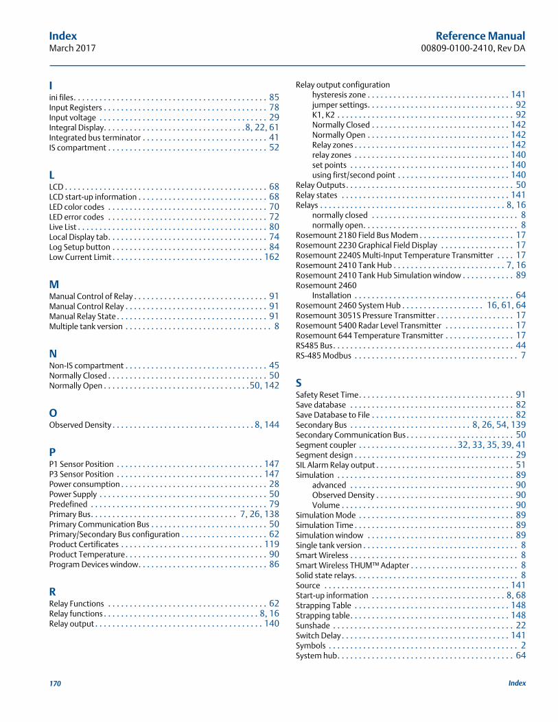
Reference Manual00809-0100-2410, Rev DA
IndexMarch 2017
Iini files. . . . . . . . . . . . . . . . . . . . . . . . . . . . . . . . . . . . . . . . . . . . . 85Input Registers . . . . . . . . . . . . . . . . . . . . . . . . . . . . . . . . . . . . . . 78Input voltage . . . . . . . . . . . . . . . . . . . . . . . . . . . . . . . . . . . . . . . 29Integral Display. . . . . . . . . . . . . . . . . . . . . . . . . . . . . . . . .8, 22, 61Integrated bus terminator . . . . . . . . . . . . . . . . . . . . . . . . . . . . . 41IS compartment . . . . . . . . . . . . . . . . . . . . . . . . . . . . . . . . . . . . . 52
LLCD . . . . . . . . . . . . . . . . . . . . . . . . . . . . . . . . . . . . . . . . . . . . . . . 68LCD start-up information . . . . . . . . . . . . . . . . . . . . . . . . . . . . . . 68LED color codes . . . . . . . . . . . . . . . . . . . . . . . . . . . . . . . . . . . . . 70LED error codes . . . . . . . . . . . . . . . . . . . . . . . . . . . . . . . . . . . . . 72Live List . . . . . . . . . . . . . . . . . . . . . . . . . . . . . . . . . . . . . . . . . . . . 80Local Display tab. . . . . . . . . . . . . . . . . . . . . . . . . . . . . . . . . . . . . 74Log Setup button . . . . . . . . . . . . . . . . . . . . . . . . . . . . . . . . . . . . 84Low Current Limit . . . . . . . . . . . . . . . . . . . . . . . . . . . . . . . . . . . 162
MManual Control of Relay . . . . . . . . . . . . . . . . . . . . . . . . . . . . . . . 91Manual Control Relay . . . . . . . . . . . . . . . . . . . . . . . . . . . . . . . . . 91Manual Relay State . . . . . . . . . . . . . . . . . . . . . . . . . . . . . . . . . . . 91Multiple tank version . . . . . . . . . . . . . . . . . . . . . . . . . . . . . . . . . . 8
NNon-IS compartment . . . . . . . . . . . . . . . . . . . . . . . . . . . . . . . . . 45Normally Closed . . . . . . . . . . . . . . . . . . . . . . . . . . . . . . . . . . . . . 50Normally Open . . . . . . . . . . . . . . . . . . . . . . . . . . . . . . . . . .50, 142
OObserved Density . . . . . . . . . . . . . . . . . . . . . . . . . . . . . . . . . 8, 144
PP1 Sensor Position . . . . . . . . . . . . . . . . . . . . . . . . . . . . . . . . . . 147P3 Sensor Position . . . . . . . . . . . . . . . . . . . . . . . . . . . . . . . . . . 147Power consumption . . . . . . . . . . . . . . . . . . . . . . . . . . . . . . . . . . 28Power Supply . . . . . . . . . . . . . . . . . . . . . . . . . . . . . . . . . . . . . . . 50Predefined . . . . . . . . . . . . . . . . . . . . . . . . . . . . . . . . . . . . . . . . . 79Primary Bus. . . . . . . . . . . . . . . . . . . . . . . . . . . . . . . . . . 7, 26, 138Primary Communication Bus . . . . . . . . . . . . . . . . . . . . . . . . . . . 50Primary/Secondary Bus configuration . . . . . . . . . . . . . . . . . . . . 62Product Certificates . . . . . . . . . . . . . . . . . . . . . . . . . . . . . . . . . 119Product Temperature. . . . . . . . . . . . . . . . . . . . . . . . . . . . . . . . . 90Program Devices window. . . . . . . . . . . . . . . . . . . . . . . . . . . . . . 86
RRelay Functions . . . . . . . . . . . . . . . . . . . . . . . . . . . . . . . . . . . . . 62Relay functions . . . . . . . . . . . . . . . . . . . . . . . . . . . . . . . . . . . . 8, 16Relay output . . . . . . . . . . . . . . . . . . . . . . . . . . . . . . . . . . . . . . . 140
Relay output configurationhysteresis zone . . . . . . . . . . . . . . . . . . . . . . . . . . . . . . . . . 141jumper settings. . . . . . . . . . . . . . . . . . . . . . . . . . . . . . . . . . 92K1, K2 . . . . . . . . . . . . . . . . . . . . . . . . . . . . . . . . . . . . . . . . . 92Normally Closed . . . . . . . . . . . . . . . . . . . . . . . . . . . . . . . . 142Normally Open . . . . . . . . . . . . . . . . . . . . . . . . . . . . . . . . . 142Relay zones . . . . . . . . . . . . . . . . . . . . . . . . . . . . . . . . . . . . 142relay zones . . . . . . . . . . . . . . . . . . . . . . . . . . . . . . . . . . . . 140set points . . . . . . . . . . . . . . . . . . . . . . . . . . . . . . . . . . . . . 140using first/second point . . . . . . . . . . . . . . . . . . . . . . . . . . 140
Relay Outputs. . . . . . . . . . . . . . . . . . . . . . . . . . . . . . . . . . . . . . . 50Relay states . . . . . . . . . . . . . . . . . . . . . . . . . . . . . . . . . . . . . . . 141Relays . . . . . . . . . . . . . . . . . . . . . . . . . . . . . . . . . . . . . . . . . . . 8, 16
normally closed . . . . . . . . . . . . . . . . . . . . . . . . . . . . . . . . . . 8normally open. . . . . . . . . . . . . . . . . . . . . . . . . . . . . . . . . . . . 8
Rosemount 2180 Field Bus Modem . . . . . . . . . . . . . . . . . . . . . . 17Rosemount 2230 Graphical Field Display . . . . . . . . . . . . . . . . . 17Rosemount 2240S Multi-Input Temperature Transmitter . . . . 17Rosemount 2410 Tank Hub . . . . . . . . . . . . . . . . . . . . . . . . . . 7, 16Rosemount 2410 Tank Hub Simulation window . . . . . . . . . . . . 89Rosemount 2460
Installation . . . . . . . . . . . . . . . . . . . . . . . . . . . . . . . . . . . . . 64Rosemount 2460 System Hub . . . . . . . . . . . . . . . . . . . 16, 61, 64Rosemount 3051S Pressure Transmitter . . . . . . . . . . . . . . . . . . 17Rosemount 5400 Radar Level Transmitter . . . . . . . . . . . . . . . . 17Rosemount 644 Temperature Transmitter . . . . . . . . . . . . . . . . 17RS485 Bus. . . . . . . . . . . . . . . . . . . . . . . . . . . . . . . . . . . . . . . . . . 44RS-485 Modbus . . . . . . . . . . . . . . . . . . . . . . . . . . . . . . . . . . . . . . 7
SSafety Reset Time. . . . . . . . . . . . . . . . . . . . . . . . . . . . . . . . . . . . 91Save database . . . . . . . . . . . . . . . . . . . . . . . . . . . . . . . . . . . . . . 82Save Database to File . . . . . . . . . . . . . . . . . . . . . . . . . . . . . . . . . 82Secondary Bus . . . . . . . . . . . . . . . . . . . . . . . . . . . . 8, 26, 54, 139Secondary Communication Bus. . . . . . . . . . . . . . . . . . . . . . . . . 50Segment coupler . . . . . . . . . . . . . . . . . . . . . . . 32, 33, 35, 39, 41Segment design . . . . . . . . . . . . . . . . . . . . . . . . . . . . . . . . . . . . . 29SIL Alarm Relay output . . . . . . . . . . . . . . . . . . . . . . . . . . . . . . . . 51Simulation . . . . . . . . . . . . . . . . . . . . . . . . . . . . . . . . . . . . . . . . . 89
advanced . . . . . . . . . . . . . . . . . . . . . . . . . . . . . . . . . . . . . . 90Observed Density . . . . . . . . . . . . . . . . . . . . . . . . . . . . . . . . 90Volume . . . . . . . . . . . . . . . . . . . . . . . . . . . . . . . . . . . . . . . . 90
Simulation Mode . . . . . . . . . . . . . . . . . . . . . . . . . . . . . . . . . . . . 89Simulation Time . . . . . . . . . . . . . . . . . . . . . . . . . . . . . . . . . . . . . 89Simulation window . . . . . . . . . . . . . . . . . . . . . . . . . . . . . . . . . . 89Single tank version . . . . . . . . . . . . . . . . . . . . . . . . . . . . . . . . . . . . 8Smart Wireless . . . . . . . . . . . . . . . . . . . . . . . . . . . . . . . . . . . . . . . 8Smart Wireless THUM™ Adapter . . . . . . . . . . . . . . . . . . . . . . . . . 8Solid state relays. . . . . . . . . . . . . . . . . . . . . . . . . . . . . . . . . . . . . . 8Source . . . . . . . . . . . . . . . . . . . . . . . . . . . . . . . . . . . . . . . . . . . 141Start-up information . . . . . . . . . . . . . . . . . . . . . . . . . . . . . . . 8, 68Strapping Table . . . . . . . . . . . . . . . . . . . . . . . . . . . . . . . . . . . . 148Strapping table. . . . . . . . . . . . . . . . . . . . . . . . . . . . . . . . . . . . . 148Sunshade . . . . . . . . . . . . . . . . . . . . . . . . . . . . . . . . . . . . . . . . . . 22Switch Delay. . . . . . . . . . . . . . . . . . . . . . . . . . . . . . . . . . . . . . . 141Symbols . . . . . . . . . . . . . . . . . . . . . . . . . . . . . . . . . . . . . . . . . . . . 2System hub. . . . . . . . . . . . . . . . . . . . . . . . . . . . . . . . . . . . . . . . . 64
170 Index
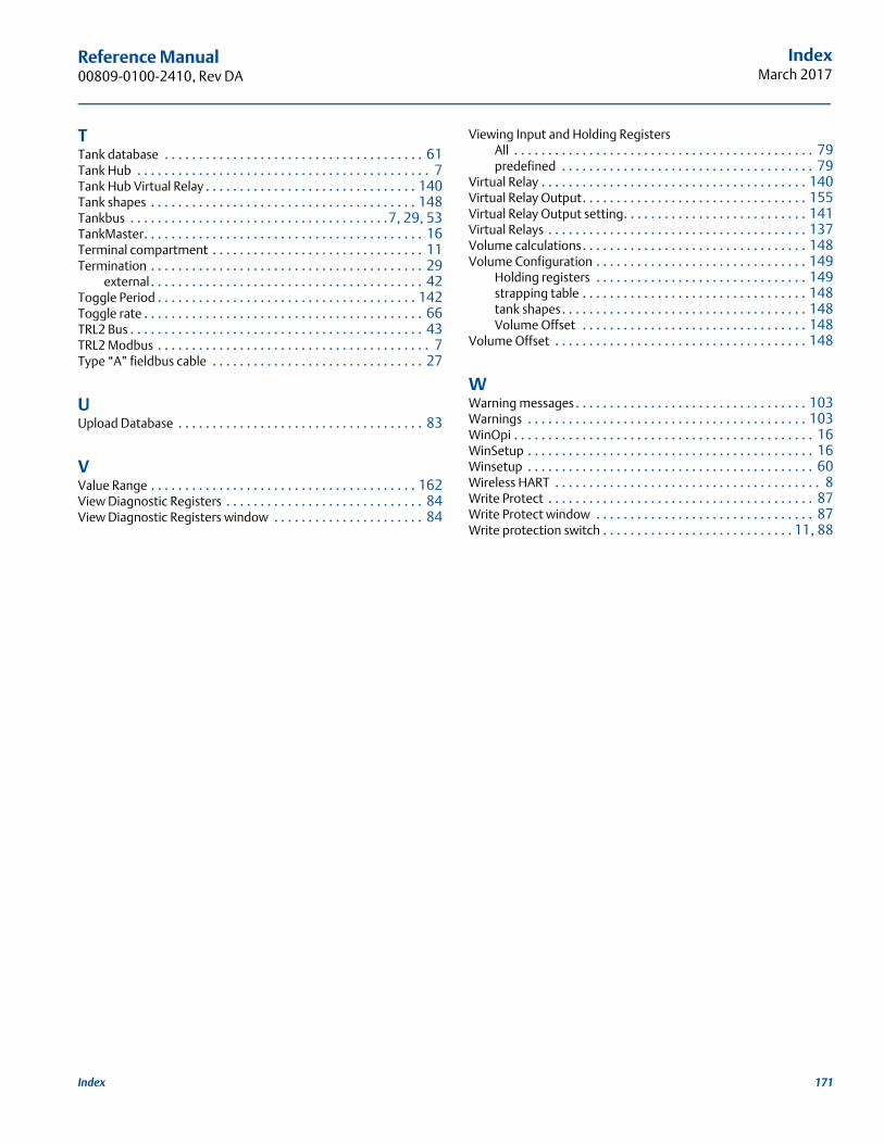
Reference Manual 00809-0100-2410, Rev DA
IndexMarch 2017
TTank database . . . . . . . . . . . . . . . . . . . . . . . . . . . . . . . . . . . . . . 61Tank Hub . . . . . . . . . . . . . . . . . . . . . . . . . . . . . . . . . . . . . . . . . . . 7Tank Hub Virtual Relay . . . . . . . . . . . . . . . . . . . . . . . . . . . . . . . 140Tank shapes . . . . . . . . . . . . . . . . . . . . . . . . . . . . . . . . . . . . . . . 148Tankbus . . . . . . . . . . . . . . . . . . . . . . . . . . . . . . . . . . . . . .7, 29, 53TankMaster. . . . . . . . . . . . . . . . . . . . . . . . . . . . . . . . . . . . . . . . . 16Terminal compartment . . . . . . . . . . . . . . . . . . . . . . . . . . . . . . . 11Termination . . . . . . . . . . . . . . . . . . . . . . . . . . . . . . . . . . . . . . . . 29
external . . . . . . . . . . . . . . . . . . . . . . . . . . . . . . . . . . . . . . . . 42Toggle Period . . . . . . . . . . . . . . . . . . . . . . . . . . . . . . . . . . . . . . 142Toggle rate . . . . . . . . . . . . . . . . . . . . . . . . . . . . . . . . . . . . . . . . . 66TRL2 Bus . . . . . . . . . . . . . . . . . . . . . . . . . . . . . . . . . . . . . . . . . . . 43TRL2 Modbus . . . . . . . . . . . . . . . . . . . . . . . . . . . . . . . . . . . . . . . . 7Type “A” fieldbus cable . . . . . . . . . . . . . . . . . . . . . . . . . . . . . . . 27
UUpload Database . . . . . . . . . . . . . . . . . . . . . . . . . . . . . . . . . . . . 83
VValue Range . . . . . . . . . . . . . . . . . . . . . . . . . . . . . . . . . . . . . . . 162View Diagnostic Registers . . . . . . . . . . . . . . . . . . . . . . . . . . . . . 84View Diagnostic Registers window . . . . . . . . . . . . . . . . . . . . . . 84
Viewing Input and Holding RegistersAll . . . . . . . . . . . . . . . . . . . . . . . . . . . . . . . . . . . . . . . . . . . . 79predefined . . . . . . . . . . . . . . . . . . . . . . . . . . . . . . . . . . . . . 79
Virtual Relay . . . . . . . . . . . . . . . . . . . . . . . . . . . . . . . . . . . . . . . 140Virtual Relay Output. . . . . . . . . . . . . . . . . . . . . . . . . . . . . . . . . 155Virtual Relay Output setting. . . . . . . . . . . . . . . . . . . . . . . . . . . 141Virtual Relays . . . . . . . . . . . . . . . . . . . . . . . . . . . . . . . . . . . . . . 137Volume calculations. . . . . . . . . . . . . . . . . . . . . . . . . . . . . . . . . 148Volume Configuration . . . . . . . . . . . . . . . . . . . . . . . . . . . . . . . 149
Holding registers . . . . . . . . . . . . . . . . . . . . . . . . . . . . . . . 149strapping table . . . . . . . . . . . . . . . . . . . . . . . . . . . . . . . . . 148tank shapes. . . . . . . . . . . . . . . . . . . . . . . . . . . . . . . . . . . . 148Volume Offset . . . . . . . . . . . . . . . . . . . . . . . . . . . . . . . . . 148
Volume Offset . . . . . . . . . . . . . . . . . . . . . . . . . . . . . . . . . . . . . 148
WWarning messages . . . . . . . . . . . . . . . . . . . . . . . . . . . . . . . . . . 103Warnings . . . . . . . . . . . . . . . . . . . . . . . . . . . . . . . . . . . . . . . . . 103WinOpi . . . . . . . . . . . . . . . . . . . . . . . . . . . . . . . . . . . . . . . . . . . . 16WinSetup . . . . . . . . . . . . . . . . . . . . . . . . . . . . . . . . . . . . . . . . . . 16Winsetup . . . . . . . . . . . . . . . . . . . . . . . . . . . . . . . . . . . . . . . . . . 60Wireless HART . . . . . . . . . . . . . . . . . . . . . . . . . . . . . . . . . . . . . . . 8Write Protect . . . . . . . . . . . . . . . . . . . . . . . . . . . . . . . . . . . . . . . 87Write Protect window . . . . . . . . . . . . . . . . . . . . . . . . . . . . . . . . 87Write protection switch . . . . . . . . . . . . . . . . . . . . . . . . . . . . 11, 88
171Index

Reference Manual00809-0100-2410, Rev DA
IndexMarch 2017
172 Index


Reference Manual00809-0100-2410, Rev DA
March 2017
Global Headquarters and Europe Regional OfficeTank GaugingEmerson Automation Solutions Box 150(Visiting address: Layoutvägen 1)SE-435 23 Mölnlycke
+46 31 337 00 00+46 31 25 30 [email protected]
North America Regional OfficeTank GaugingEmerson Automation Solutions 6005 Rogerdale RoadMail Stop NC 136Houston TX 77072United States
+1 281 988 4000 or +1 800 722 [email protected]
Latin America Regional OfficeEmerson Automation Solutions 1300 Concord Terrace, Suite 400Sunrise, FL 33323, USA
+1 954 846 5030+1 954 846 [email protected]
Asia Pacific Regional OfficeEmerson Automation Solutions Asia Pacific Pte Ltd1 Pandan CrescentSingapore 128461
+65 6777 8211+65 6777 0947 [email protected]
Middle East and Africa Regional OfficeEmerson Automation SolutionsEmerson FZE P.O. Box 17033Jebel Ali Free Zone - South 2Dubai, United Arab Emirates
+971 4 8118100+971 4 8865465 [email protected]
Linkedin.com/company/Emerson-Automation-Solutions
Twitter.com/Rosemount_News
Facebook.com/Rosemount
Youtube.com/user/RosemountMeasurement
Google.com/+RosemountMeasurement
Standard Terms and Conditions of Sale can be found on the Terms and Conditions of Sale page.The Emerson logo is a trademark and service mark of Emerson Electric Co.Rosemount and Rosemount logotype are trademarks of Emerson.All other marks are the property of their respective owners.© 2017 Emerson. All rights reserved.


