This installation guide provides basic guidelines for the Rosemount® 702. It does not provide instructions for detailed configuration, diagnostics, maintenance, service, troubleshooting, or installations. Refer to the Rosemount 702 Reference Manual (Document Number 00809-0200-4702) for more instruction. This guide and the manual are available electronically on www.rosemount.com.
WARNING
Explosions could result in death or serious injury: Installation of this transmitter in an explosive environment must be in accordance with the appropriate local, national, and international standards, codes, and practices. Please review the Product Certifications section for any restrictions associated with a safe installation.
• Before connecting a Field Communicator in an explosive atmosphere, ensure the instruments are installed in accordance with intrinsically safe or non-incendive field wiring practices.
Electrical shock can result in death or serious injuryAvoid contact with the leads and terminals. High voltage that may be present on leads can cause electrical shock.This device complies with Part 15 of the FCC Rules. Operation is subject to the following conditions. This device may not cause harmful interference. This device must accept any interference received, including interference that may cause undesired operation.This device must be installed to ensure a minimum antenna separation distance of 8 in. (20 cm) from all persons.The power module may be replaced in a hazardous area. The power module has surface resistivity greater than one gigaohm and must be properly installed in the wireless device enclosure. Care must be taken during transportation to and from the point of installation to prevent electrostatic charge build-up.
IMPORTANT NOTICEShipping considerations for wireless products:
The unit was shipped to you without the power module installed. Please remove the power module prior to shipping the unit.Each power module contains two “C” size primary lithium batteries. Primary lithium batteries are regulated in transportation by the U.S. Department of Transportation, and are also covered by IATA (International Air Transport Association), ICAO (International Civil Aviation Organization), and ARD (European Ground Transportation of Dangerous Goods). It is the responsibility of the shipper to ensure compliance with these or any other local requirements. Please consult current regulations and requirements before shipping.
Emerson Process Management Rosemount Division8200 Market BoulevardChanhassen, MN USA 55317T (US) (800) 999-9307T (Intnl) (952) 906-8888F (952) 949-7001
The Power Module should not be installed on any wireless device until the Smart Wireless Gateway (“Gateway”) is installed and functioning properly. Wireless devices should be powered up in order of proximity from the Gateway, beginning with the closest device, then working outward from the Gateway. This results in a simpler and faster network installation. Enable Active Advertising on the Gateway ensures that new devices are able to join the network faster. For more information see the Smart Wireless Gateway Manual (Document No. 00809-0200-4420).
Antenna PositionThe antenna should be positioned vertically, either straight up or straight down, and should be approximately 3 ft. (1 m) from any large structure, building, or conductive surface to allow for clear communication to other devices.
Figure 1. Antenna Position
Conduit EntriesUpon installation, ensure that each conduit entry is either sealed with a conduit plug with appropriate thread sealant, or has an installed conduit fitting or cable gland with appropriate thread sealant.
Figure 2. Conduit Entry
Conduit EntryConduit Entry
Quick Installation Guide00825-0200-4702, Rev CA
April 2010Rosemount 702
Field Communicator ConnectionsThe Power Module needs to be installed before the Field Communicator can interface with the 702.
STEP 1: PHYSICAL INSTALLATIONThe Rosemount 702 and all other wireless devices should not be set up until after the Smart Wireless Gateway has been installed and is functioning properly.
The Rosemount 702 can be installed in one of two configurations: Direct Mount, where the switch is connected directly to the 702 housing’s conduit entry, or Remote Mount, where the switch is mounted separate from the 702 housing, then connected to the 702 via conduit. Choose the installation sequence that corresponds to the mounting configuration.
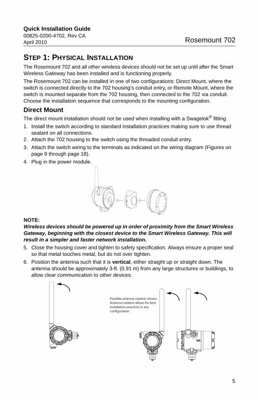
Direct MountThe direct mount installation should not be used when installing with a Swagelok® fitting.
1. Install the switch according to standard installation practices making sure to use thread sealant on all connections.
2. Attach the 702 housing to the switch using the threaded conduit entry.
3. Attach the switch wiring to the terminals as indicated on the wiring diagram (Figures on page 9 through page 18).
4. Plug in the power module.
NOTE:Wireless devices should be powered up in order of proximity from the Smart Wireless Gateway, beginning with the closest device to the Smart Wireless Gateway. This will result in a simpler and faster network installation.
5. Close the housing cover and tighten to safety specification. Always ensure a proper seal so that metal touches metal, but do not over tighten.
6. Position the antenna such that it is vertical, either straight up or straight down. The antenna should be approximately 3-ft. (0.91 m) from any large structures or buildings, to allow clear communication to other devices.
Possible antenna rotation shown.Antenna rotation allows for bestinstallation practices in anyconfiguration.
Quick Installation Guide00825-0200-4702, Rev CA
April 2010Rosemount 702
STEP 1 CONTINUED...
Remote Mount1. Install the switch according to standard installation practices making sure to use thread
sealant on all connections.2. Run wiring (and conduit if necessary) from the switch to the 702.
3. Pull the wiring through the threaded conduit entry of the 702.
4. Attach the switch wiring to the terminals as indicated on the wiring diagram (Figures on page 9 through page 18).
5. Plug in the power module.
NOTE:Wireless devices should be powered up in order of proximity from the Smart Wireless Gateway, beginning with the closest device to the Gateway. This will result in a simpler and faster network installation.
6. Close the housing cover and tighten to safety specification. Always ensure a proper seal so that metal touches metal, but do not over tighten.
7. Position the antenna such that it is vertical, either straight up or straight down. The antenna should be approximately 3-ft. (0.91 m) from any large structures or buildings, to allow clear communication to other devices.
STEP 2: VERIFY OPERATIONThere are four ways to verify operation: using the optional local display (LCD), using the Field Communicator, using the Smart Wireless Gateway’s integrated web interface, or by using AMS® Suite Wireless Configurator.
Local DisplayDuring normal operation, the LCD should display the PV value at the update rate, in up to 1 minute intervals. Refer to the Rosemount 702 Manual (00809-0200-4702) for error codes and other LCD messages. Press the Diagnostic button to display the TAG, Device ID, Network ID, Network Join Status and Device Status screens.
Field CommunicatorFor HART Wireless transmitter communication, a 702 DD is required.
Smart Wireless GatewayIn the Gateway’s integrated web server, navigate to the Explorer>Status page. This page shows whether the device has joined the network and is communicating properly.
NOTE:It may take several minutes for the device to join the network.
NOTE:If the device joins the network and immediately has an alarm present, it is likely caused by the sensor configuration. Check the sensor wiring (see Rosemount 702 Terminal Diagram on page 9) and the sensor configuration (see 702 Fast Key Sequence on page 18).
Searching for Network Joining Network Connected with 1 Parent
Connected with 2 Parents
Function Key Sequence Menu Items
Communications 3, 3 Join Status, Wireless Mode, Join Mode, Number of Available Neighbors, Number of Advertisements Heard, Number of Join Attempts
N E T w K
S R C H N G
n e t w k
N E G O T
n e t w k
L I M - O P
n e t w k
O K
7
Quick Installation Guide00825-0200-4702, Rev CA
April 2010Rosemount 702
Figure 4. Smart Wireless Gateway Network Settings
AMS® Suite Wireless ConfiguratorWhen the device has joined the network, it will appear in the Device Manager as illustrated below.
TroubleshootingIf the device is not joined to the network after power up, verify the correct configuration of the Network ID and Join Key, and that Active Advertising has been enabled on the Smart Wireless Gateway. The Network ID and Join Key in the device must match the Network ID and Join Key of the Gateway.
The Network ID and Join Key may be obtained from the Gateway on the Setup>Network>Settings page of the web server (see Figure 4 on page 8). The Network ID and Join Key may be changed in the wireless device by following the Fast Key sequence.
STEP 3: WIRING SWITCHES AND SENSORS, REFERENCE INFORMATION
The 702 Discrete Transmitter will accept the input from one or two single pole single throw switches on inputs S1 and S2. The wireless output of the transmitter will be both a primary variable (PV) and a secondary variable (SV). The PV is determined by the S1 input. The SV is determined by the S2 input. A closed switch drives a TRUE output. An Open switch drives a FALSE output.
Figure 6. Single, Dual Input
Function Key Sequence Menu Items
Wireless 2, 1, 1 Join Device to Network
Single Input Dual Input
S1
CMN
S2CMN
S1
CMN
S2
CMN
9
Quick Installation Guide00825-0200-4702, Rev CA
April 2010Rosemount 702
Dry Contact Inputs (Continued)...
If inverted output is selected, any outputs will be inverted, as shown below.
Dual Input, Limit Contact Logic
When configured for Limit Contact Logic, the 702 Discrete Transmitter will accept the input from two single pole single throw switches on inputs S1 and S2, and will use limit contact logic for the determination of the wireless outputs.
Dry Contact Inputs (Continued)...If inverted output is selected, any outputs will be inverted, as shown below.
Dual Input, Opposing Contact Logic
When configured for Opposing Contact Logic, the 702 Discrete Transmitter will accept the input from a double pole single throw switches on inputs S1 and S2, and will use opposing contact logic for the determination of the wireless outputs.
Figure 8. Dual Input, Opposing Contact
If inverted output is selected, any outputs will be inverted, as shown below.
The Liquid Hydrocarbon Detection configuration is intended for use with the Tyco® TraceTek® Fast Fuel Sensor, or TraceTek sensing cable.
Figure 10. Fuel Sensor Connection Diagram
The connections to the Fast Fuel Sensor TraceTek sensing cable are made by matching the appropriately colored wires to the matching colored termination lugs.
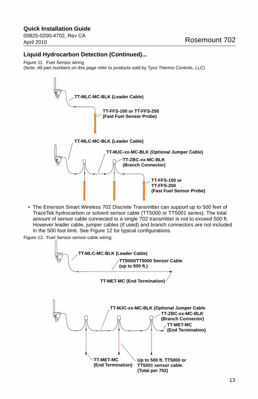
• The Emerson Smart Wireless 702 Discrete Transmitter can support up to 3 Fast Fuel sensors. These Fast Fuel sensors are connected using TraceTek Modular Leader Cable (TT-MLC-MC-BLK), optional modular jumper cables (TT-MJC-xx-MC-BLK) and branching connectors (TT-ZBC-MC-BLK) as suggested in Figure 11.
Liquid Hydrocarbon Detection (Continued)...Figure 11. Fuel Sensor wiring (Note: All part numbers on this page refer to products sold by Tyco Thermo Controls, LLC)
• The Emerson Smart Wireless 702 Discrete Transmitter can support up to 500 feet of TraceTek hydrocarbon or solvent sensor cable (TT5000 or TT5001 series). The total amount of sensor cable connected to a single 702 transmitter is not to exceed 500 ft. However leader cable, jumper cables (if used) and branch connectors are not included in the 500 foot limit. See Figure 12 for typical configurations.
Up to 500 ft. TT5000 or TT5001 sensor cable (Total per 702)
TT-MET-MC(End Termination)
Quick Installation Guide00825-0200-4702, Rev CA
April 2010Rosemount 702
Liquid Hydrocarbon Detection (Continued)...The following figures show how the AMS® Suite Intelligent Device Manager overview screen looks for the 702 Liquid Hydrocarbon Detection option, for each of the leak sensor conditions.
Figure 13. Normal - AMS Device Manager Overview screen
Table 1. Liquid Hydrocarbon Detection Interface, for Modbus mapping
Table 1 describes use of the 702 Discrete Transmitter for hydrocarbon detection in other communications protocols such as Modbus or OPC. It is imperative that both PV and SV be mapped to the host system so as to make a good interpretation of the condition and status of the leak detector.
In addition, system considerations must be observed to ensure that the device is still connected to the wireless network and reporting values. On an Emerson Smart Wireless Gateway, this can be done by referring to the parameter: PV_HEALTHY. PV_HEALTHY has a “True” state when the device is on the network and its updates are current, not late or stale, and the device is functioning properly. A “False” state of PV_HEALTHY means that the device is either off of the network, the data updates are not current, or that there is a malfunction of the device (such as an electronics failure). In the case of a “False” state of PV_HEALTHY, it is recommended to assume that the device is not connected to the network and to take appropriate action.
Below is a shot of the gateway screen where the PV, SV and PV_HEALTHY variables and parameter can be mapped.
1.0 1.0 Normal condition, no leak detected, sensor status good0.0 1.0 or 0.0 Leak detected, sensor status good1.0 0.0 Sensor Not Connected, Assume Leak, take appropriate action
IMPORTANT NOTICE
It is imperative that both PV and SV be mapped to the host system so that the diagnostic information on the sensor status is captured.
Liquid Hydrocarbon Detection (Continued)...• The Fast Fuel Sensor Diagnostics will propagate via the SV variable. This additional
information will provide additional sensor Status information while using the TraceTek Fast Fuel Sensor.
• Warning: If a device becomes not present on the wireless network, Appropriate action must be taken by the host system.
Important notes regarding the use of Tyco TraceTek Fast Fuel Sensor and TraceTek sensing cable:
• Tyco TraceTek sensors must be installed as per manufacturer recommendations. • Do not run the 702 Discrete Transmitter for long periods (more than two weeks) with a
Tyco fuel sensor in the leak state as this will more rapidly deplete the power module.
17
Quick Installation Guide00825-0200-4702, Rev CA
April 2010Rosemount 702
Field Communicator UseNOTE:In order to communicate with a Field Communicator, power the 702 by connecting the power module
Table 2. 702 Fast Key Sequence
Figure 17. Field Communicator Connections
Function Key Sequence Menu Items
Device Information 2,2,4,3 Manufacturer Model, Final Assembly Number, Universal, Field Device, Software, Hardware, Descriptor, Message, Date, Model Number I, II, III, SI Unit Restriction, Country
Guided Setup 2, 1 Join Device to Network, Configure Update Rate, Configure Sensor, Calibrate Sensor, Configure Display, Configure Process Alarms
Manual Setup 2, 2 Wireless, Process Sensor, Percent of Range, Device Temperatures, Device Information, Device Display, Other
Wireless 2, 2, 1 Network ID, Join Device to Network, Configure Update Rate, Configure Broadcast Power Level, Power Mode, Power Source
Approved Manufacturing LocationsRosemount Inc. – Chanhassen, Minnesota, USAEmerson Process Management GmbH & Co. - Karlstein, GermanyEmerson Process Management Asia Pacific Private Limited - Singapore
European Union Directive InformationThe EC Declaration of Conformity begins on page 23, and the most recent revision can be found at www.rosemount.com under Documentation.
Telecommunication ComplianceAll wireless devices require certification to ensure that they adhere to regulations regarding the use of the RF spectrum. Nearly every country requires this type of product certification. Emerson is working with governmental agencies around the world to supply fully compliant products and remove the risk of violating country directives or laws governing wireless device usage.
FCC and ICThis device complies with Part 15 of the FCC Rules. Operation is subject to the following conditions: This device may not cause harmful interference. This device must accept any interference received, including interference that may cause undesired operation.
This device must be installed to ensure a minimum antenna separation distance of 20 cm from all persons.
Ordinary Location Certification for FM ApprovalsAs standard, the transmitter has been examined and tested to determine that the design meets basic electrical, mechanical, and fire protection requirements by FM Approvals, a nationally recognized testing laboratory (NRTL) as accredited by the Federal Occupational Safety and Health Administration (OSHA).
Hazardous Locations Certificates
North American Certifications
FM ApprovalsI5 FM Intrinsically Safe, Non-Incendive and Dust Ignition-Proof
Intrinsically Safe for Class I/II/III, Division 1, Groups A, B, C, D, E, F, and G.Zone Marking: Class I, Zone 0, AEx ia llCTemperature Codes T4 (-50 °C <= Tamb <= 70 °C), T5 (-50 °C <= Tamb <= 40 °C)Non-incendive for Class I, Division 2, Groups A, B, C, and D. Dust Ignition-proof for Class II/III, Division 1, Groups E, F, and G. Intrinsically Safe and non-incendive when installed in accordance with Rosemount drawing 00702-1000.For use with Rosemount SmartPower® Options P/N 753-9220-0001 only.Enclosure Type 4X / IP66 / IP67
19
Quick Installation Guide00825-0200-4702, Rev CA
April 2010Rosemount 702
CSA InternationalI6 CSA Intrinsically Safe
Intrinsically Safe for Class I, Division 1, Groups A, B, C, and D.Temp Code T3CEnclosure Type 4X / IP66 / IP67For use with Rosemount SmartPower Options P/N 753-9220-0001 onlyIntrinsically Safe when installed per Rosemount drawing 00702-1020
European Certifications
I1 ATEX Intrinsic SafetyCertificate No.: BASEEFA07ATEX0239X II 1GEx ia IIC T4 (-60 °C <= Tamb <= 70 °C), Ex ia IIC T5 (-60 °C <= Tamb <= 40 °C)
1180IP66 / IP67For use with Rosemount SmartPower ™ options P/N 753-9220-XXXX onlySpecial conditions for safe use (X)The surface resistivity of the antenna is greater than 1 gigaohm. To avoid electrostatic charge build-up, it must not be rubbed or cleaned with solvents or a dry cloth.
IECEx System CertificationsI7 IECEx Intrinsic Safety
Certificate No.: IECExBAS07.0082XEx ia IIC T4 (-60 °C <= Tamb <= 70 °C), Ex ia IIC T5 (-60 °C <= Tamb <= 40 °C)IP66 / IP67For use with Rosemount SmartPower options P/N 753-9220-XXXX onlySpecial conditions for safe use (X)The surface resistivity of the antenna is greater than 1 gigaohm. To avoid electrostatic charge build-up, it must not be rubbed or cleaned with solvents or a dry cloth.
TABLE 3. Sensor Parameters
Dry Contact InputsOption Code 22
Liquid Hydrocarbon DetectionOption Code 61
Uo = 6.51 V Uo = 7.8 VIo = 26 mA Io = 92 mAPo = 42.6 mW Po = 180 mWCo = 10.9 uF Co = 9.2 uFLo = 25 mH Lo = 5 mH
TABLE 4. Sensor Parameters
Dry Contact InputsOption Code 22
Liquid Hydrocarbon DetectionOption Code 61
Uo = 6.51 V Uo = 7.8 VIo = 26 mA Io = 92 mAPo = 42.6 mW Po = 180 mWCo = 10.9 uF Co = 9.2 uFLo = 25 mH Lo = 5 mH
I3 China Intrinsic SafetyCertificate No. (Manufactured in Chanhassen or Singapore): GYJ081015Ex ia IIC T4/T5
Special Condition for Safe Use
1. The temperature class depends on ambient temperature range as follows:
2. Safety Parameters:
3. The cable entry of transmitter should be protected to ensure the degree of protection of the enclosure IP 20 (GB4208-1993) at least.
4. The cables between transmitter and associated apparatus should be shielded cables (the cables must have insulated shield). The cable core section area should be more than 0.5 mm2. The shield has to be grounded reliably. The wiring has to not be affected by electromagnetic disturbance.
5. COMM interface is forbidden to use in hazardous location.
6. Associated apparatus should be installed in a safe location, and during installation, operation, and maintenance, the regulations of the instruction manual have to be strictly observed.
7. End users are not permitted to change any components insides.
8. During installation, use and maintenance transmitter, observe the following standards.
a. GB3836.13-1997 “Electrical apparatus for explosive gas atmospheres Part 13: Repair and overhaul for apparatus used in explosive gas atmospheres”
b. GB3836.15-2000 “Electrical apparatus for explosive gas atmospheres Part 15: Electrical installations in hazardous area (other than mines)”
c. GB3836.16-2006 “Electrical apparatus for explosive gas atmospheres Part 16: Inspection and maintenance of electrical installation (other than mines)”
d. GB50257-1996 “Code for construction and acceptance of electric device for explosion atmospheres and fire hazard electrical equipment installation engineering”
9. Note all installation practices must be followed and if connected to a device that doesn't meet these same approval requirements, the overall system installed approval may be affected.
Figure 18. EC Declaration of Conformity for Rosemount 702
EC Declaration of Conformity No: RMD 1066 Rev. B
We,
Rosemount Inc. 8200 Market Boulevard Chanhassen, MN 55317-9685 USA
declare under our sole responsibility that the product,
Model 702 Wireless Discrete Transmitter manufactured by,
Rosemount Inc. 8200 Market Boulevard Chanhassen, MN 55317-9685 USA
to which this declaration relates, is in conformity with the provisions of the European Community Directives, including the latest amendments, as shown in the attached schedule. Assumption of conformity is based on the application of the harmonized standards and, when applicable or required, a European Community notified body certification, as shown in the attached schedule.
(date of issue)
(function name - printed)
(name - printed)
(signature)
Robert J. Karschnia
Vice President, Technology
28 January 2009
23
Quick Installation Guide00825-0200-4702, Rev CA
April 2010Rosemount 702
ScheduleNo: RMD 1066 Rev. B
Page 2 of 3 \\intruder\userdata\CE_Declarations\702\702_RMD1066B.doc
EMC Directive (2004/108/EC)
All Models with ”Operating Frequency and Protocol Code 1” EN 61326-1:1997 with amendments A1, A2, and A3
All Models with ”Operating Frequency and Protocol Code 3” EN 61326-1:2006 and EN 61326-2-3:2006
R&TTE Directive (1999/5/EC)
All Models with ”Output Code X” and ”Operating Frequency and Protocol Code 1” EN 301 489-1: V 1.4.1 2002, EN 301 489-17: V1.2.1 2002 EN 60950-1: 2001 EN 300 328 V 1.6.1 (2004-11)
Country Restriction Bulgaria General authorization required for outdoor use and public service France Outdoor use limited to 10mW e.i.r.p. Italy If used ourside of own primises, general authorization is required Norway May be restricted in the geographical area within a radius of 20km from the center of Ny-Alesund Romainia Use on a secondary basis. Individual license required.
All Models with ”Output Code X” and ”Operating Frequency and Protocol Code 3” EN 301 489-1: V 1.4.1 2002, EN 301 489-17: V1.2.1 2002 EN 61010-1: 2001 (Second Addition) EN 300 328 V 1.6.1 (2004-11)
All Models with ”Output Code X” and ”Operating Frequency and Protocol Code 3” With the Extended Range Antenna option code “WM”
Country Restriction Bulgaria General authorization required for outdoor use and public service France Outdoor use limited to 10mW e.i.r.p. Italy If used ourside of own primises, general authorization is required Norway May be restricted in the geographical area within a radius of 20km from the center of Ny-Alesund Romainia Use on a secondary basis. Individual license required.