Department of Electrical and Computer Engineering Faculty of Sciences and Technology University of Coimbra ROSint - Integration of a mobile robot in ROS architecture André Gonçalves Araújo A Dissertation presented for the degree of Master of Science in Electrical and Computer Engineering Coimbra, July 2012
Transcript
Department of Electrical and Computer Engineering
Faculty of Sciences and Technology
University of Coimbra
ROSint - Integration of a mobilerobot in ROS architecture
André Gonçalves Araújo
A Dissertation presented for the degree of
Master of Science in Electrical and Computer Engineering
Coimbra, July 2012
ROSint - Integration of a mobilerobot in ROS architecture
Supervisor:
Prof. Doutor Rui P. Rocha
Co-Supervisors:
Eng. David Portugal
Eng. Micael Couceiro
Juries:
Prof. Doutor Armando Sousa
Prof. Doutor Jorge Lobo
Prof. Doutor Lino Marques
Prof. Doutor Rui P. Rocha
Project report written for the dissertation subject, included in the
Electrical and Computer Engineering Course, submitted in partial fulfillment
for the degree of Master of Science in Electrical and Computer Engineering.
Coimbra , July 2012
Agradecimentos
Em primeiro lugar quero começar por agradecer em especial ao Professor Doutor Rui
Rocha na minha orientação neste trabalho, prezando pelo seu rigor, organização e es-
timulação constante, onde sempre depositou bastante confiança nas capacidades do meu
trabalho.
Quero também agradecer, pelo apoio incondicional dos meus co-orientadores David Por-
tugal e Micael Couceiro, pela sua persistência, motivação e ajuda nos momentos mais
difíceis deste trabalho. Para além de orientadores, levo desta experiência dois grandes
amigos.
Agradeço também ao Instituto de Sistemas e Robótica, pelas óptimas condições disponi-
bilizadas, bem como todos os meus colegas de trabalho por toda a boa disposição e
companheirismo, que contribuíram para o meu bom estado de espirito, para progredir
neste trabalho.
Aos meus pais, agradeço profundamente pelo empenho, dedicação e paciência que propul-
sionaram na minha boa formação, dando me sempre a oportunidade de ter tudo de bom
e melhor, obrigado do fundo do coração. Não podendo esquecer, todo o apoio e carinho
prestado pela a minha família e namorada ao longo destes anos: Ângela, avós, tios e
primos.
Não podia deixar de agradecer a todos os amigos de Braga, em especial atenção ao Aníbal,
Bruno, Carlos, Catarina, Joana, Luís, Maura, Rui, Sérgio, Telmo e Vitor por nunca se
esqueceram de mim, apesar do pouco tempo que lhes disponibilizei. Aos amigos de Coim-
bra, André Oliveira, André Santos, Gonçalo Ferreira, Gonçalo Palaio, João, Nuno, Patrí-
cia Monteiro, Sérgio, as irmãs Patrícia e Filipa Ferraz e muitos outros, que me ajudaram
desde o primeiro dia em Coimbra até ao final.
Um obrigado muito especial, pelo tempo disponibilizado e atenção, por parte das pessoas
v
vi
que contribuíram para a realização deste trabalho Amadeu Fernandes (MRL, ISR), Beat-
riz Garrido (DEI, FCTUC), Gonçalo Cabrita (LSE, ISR) e Michael Ferguson (University
of Albany / Willow Garage).
Para finalizar, por todos os momentos felizes, pessoas conhecidas, vivências e experiências
passadas e especialmente a pessoa que me tornaste hoje, muito obrigado Coimbra, que
me deixas saudade para a vida.
Abstract
The goal of this work is to provide hardware abstraction and intuitive operation modes
to decrease the development and implementation time of robotic platforms, thus allowing
researchers to focus in their main scientific research motivations, e.g., search and rescue,
multi-robot surveillance, swarm robotics, among others. To that end, this work presents
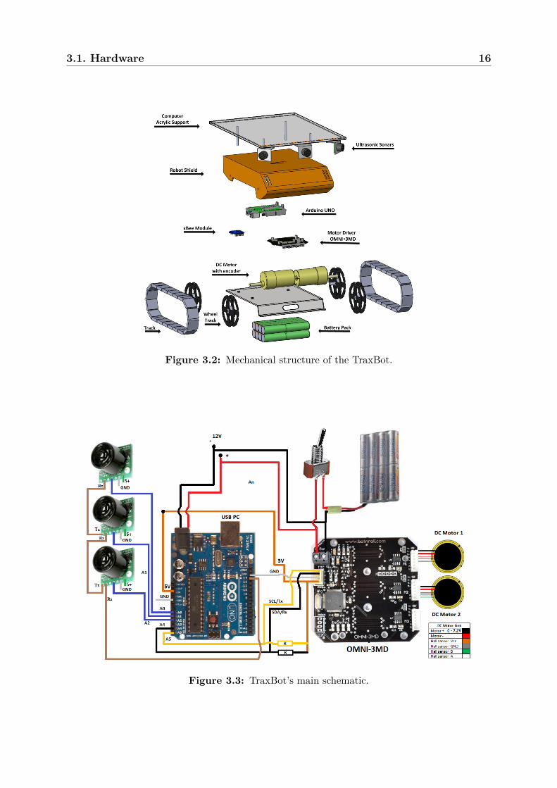
the development of a compact mobile low-cost robotic platform, denoted as TraxBot, de-
veloped and assembled at the Institute of Systems and Robotics (ISR), which has been
fully integrated in the well-known Robot Operating System (ROS) framework.
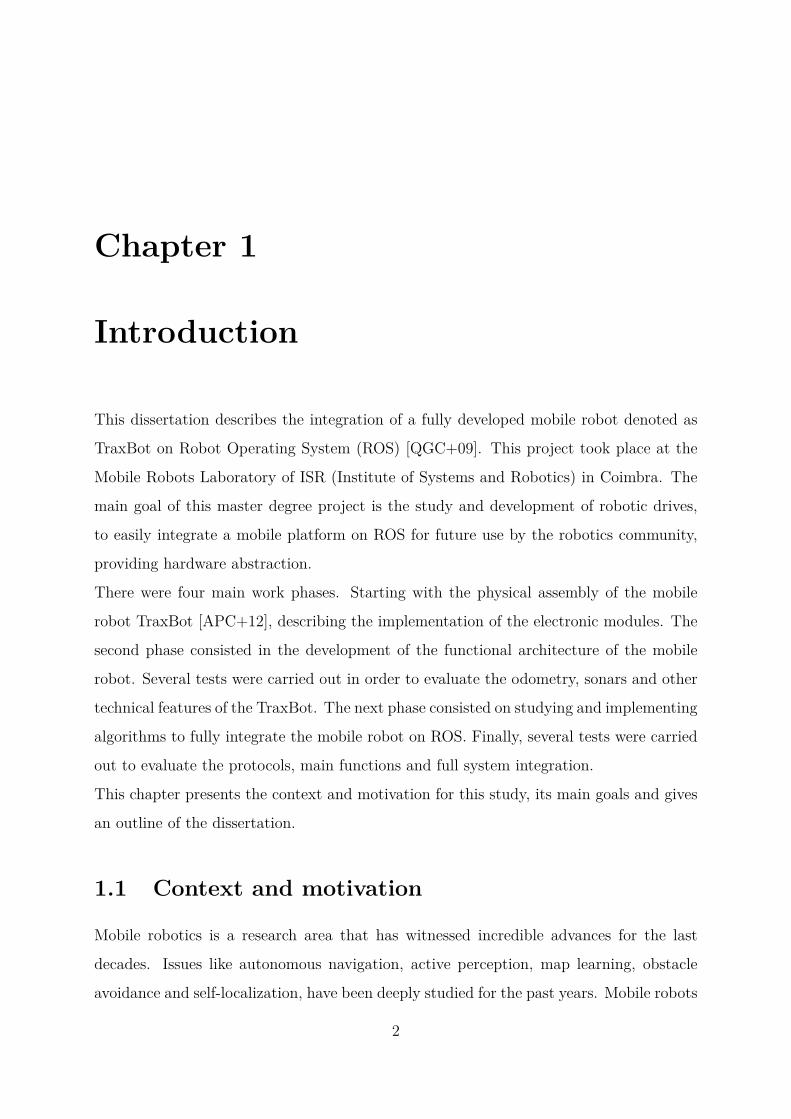
Furthermore, several available mobile robots are compared and discussed in terms of their
physical dimensions, hardware, sensors, communication abilities, motion, maximum run
time and special features. This provides support to the reader on the decision-making
acquisition process of a cost-effective robotic platform.
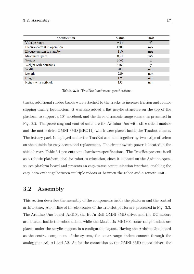
Beyond the survey’s results, the robotic system assembly, with a full description of its
components as well as detailed information about the microcontroller programming, de-
velopment and testing are also presented. The potentialities of the TraxBot are described,
which combined with the herein presented ROS driver; provide several tools for data anal-
ysis and easiness of interaction between multiple robots, sensors and teleoperation devices.
In order to validate the approach, several experimental tests were conducted using both
real and mixed teams of real and virtual robots.
Key Words: ROS, Arduino, mobile robot, embedded system, integration.
Resumo
O objectivo deste trabalho é contribuir, através de abstracção de hardware e criação de
modos de operação intuitivos, na redução drástica do tempo de desenvolvimento e im-
plementação de plataformas móveis. Isto permite aos investigadores focarem-se na sua
motivação principal, tal como busca e salvamento, segurança com múltiplos robôs, swarm
robotics, entre outros. Assim sendo, desenvolveu-se no Instituto de Sistemas e Robótica
(ISR), uma plataforma robótica móvel, denominada TraxBot para simplificar este ob-
jectivo. A plataforma foi completamente integrada no ROS (Robot Operating System),
bastante em voga actualmente.
Para além disso, é apresentada uma vasta gama de robôs, comparando e discutindo as
suas características físicas, dimensões, sensores incorporados, poder de processamento,
particularidades de hardware, tempo de autonomia bem como a relação qualidade preço.
O TraxBot é apresentado com a total descrição dos seus componentes, dando ênfase a
detalhes sobre programação, unidade de processamento, características sensoriais e abor-
dagem usada para o desenvolvimento deste robô. É de referir ainda, que as potencialidades
da plataforma são discutidas, juntamente com o driver de integração deste robô em ROS.
Esta integração disponibiliza uma grande variedade de ferramentas e métodos de progra-
mação, sendo possível a interacção entre múltiplos robôs, sensores e tele-operação, entre
outras aplicações. Para validar a abordagem, foram realizados vários teste, a nível de de-
sempenho da plataforma, bem como testes usando robôs reais juntamente com simulação
As opposed to the first version, this new version allows to stream data (Algorithm 4.2).
This results in fewer requests, freeing the channel of communication. Another option of
this new driver is the ability to enable and disable a debug option.
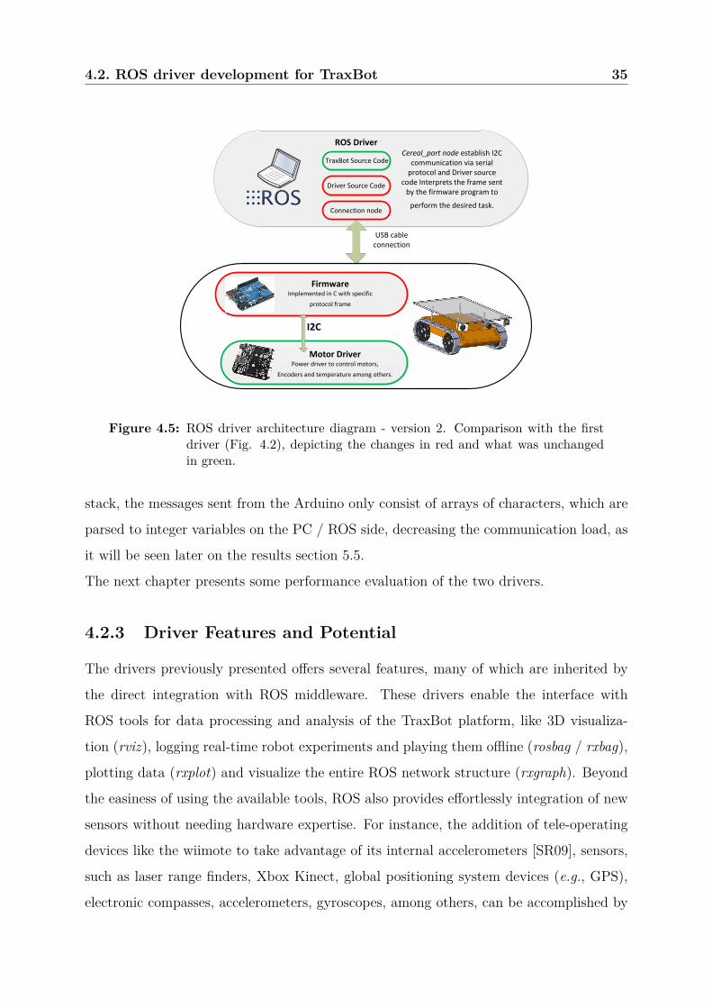
Fig. 4.5 presents the driver architecture and compares it to the first version, depict-
ing the changes in red and what was unchanged in green. The most significant changes
were carried out in the TraxBot platform (i.e., Arduino firmware), where the algorithm
was implemented due to the communication protocol mentioned above. In the PC /
ROS side, changes mainly consist on using the functions from the communication stack
serial_communication instead of the rosserial stack. Another relevant change was the up-
grade of the "Driver Source Code" which allows interpreting the messages and publishing
or subscribing the relevant information in ROS. That information is then used by other
nodes as Fig. 4.5 depicts, e.g. "TraxBot Source Code". However, the main difference
between the two versions consists on how the ROS topics are published. From the rosse-
rial point of view, libraries are added to the Arduino source code, in order to emulate
ROS language directly in Arduino code. This results in high overhead in communication
between PC / ROS and the Arduino, due to the structures used for example to publish
messages from the Arduino side. On the other hand, using the serial_communication
4.2. ROS driver development for TraxBot 34
Algorithm 4.2 TraxBot Resident Firmware version 2, running in the Arduino Uno board.
4.2. ROS driver development for TraxBot 35
ROS Driver
Connection node
TraxBot Source CodeCereal_port node establish I2C
communication via serial protocol and Driver source
code Interprets the frame sent by the firmware program to
perform the desired task.
Driver Source Code
USB cable connection
Firmware Implemented in C with specific
protocol frame
Motor Driver Power driver to control motors,
Encoders and temperature among others.
I2C
Figure 4.5: ROS driver architecture diagram - version 2. Comparison with the firstdriver (Fig. 4.2), depicting the changes in red and what was unchangedin green.
stack, the messages sent from the Arduino only consist of arrays of characters, which are
parsed to integer variables on the PC / ROS side, decreasing the communication load, as
it will be seen later on the results section 5.5.
The next chapter presents some performance evaluation of the two drivers.
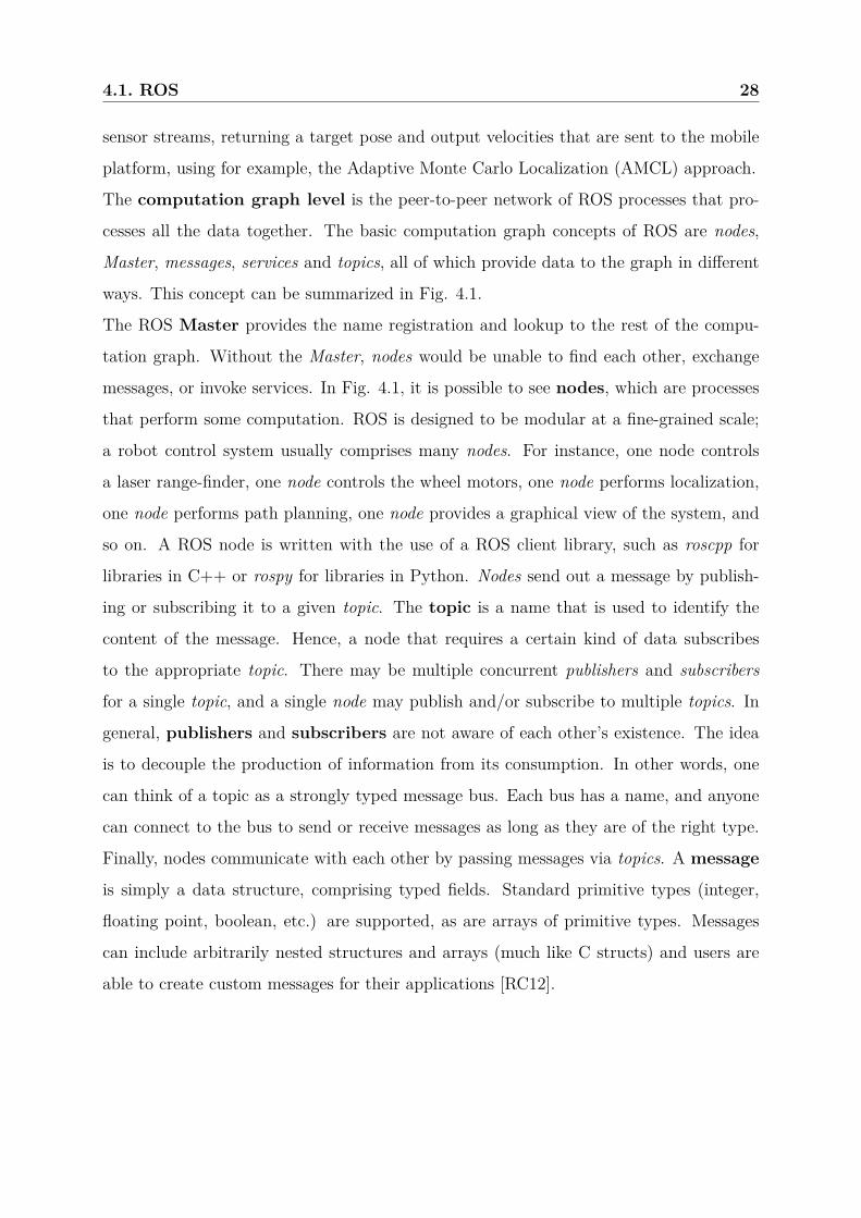
4.2.3 Driver Features and Potential
The drivers previously presented offers several features, many of which are inherited by
the direct integration with ROS middleware. These drivers enable the interface with
ROS tools for data processing and analysis of the TraxBot platform, like 3D visualiza-
tion (rviz), logging real-time robot experiments and playing them offline (rosbag / rxbag),
plotting data (rxplot) and visualize the entire ROS network structure (rxgraph). Beyond
the easiness of using the available tools, ROS also provides effortlessly integration of new
sensors without needing hardware expertise. For instance, the addition of tele-operating
devices like the wiimote to take advantage of its internal accelerometers [SR09], sensors,
such as laser range finders, Xbox Kinect, global positioning system devices (e.g., GPS),
electronic compasses, accelerometers, gyroscopes, among others, can be accomplished by
4.2. ROS driver development for TraxBot 36
Figure 4.6: Network topology example with multiple robots, sensors, teleoperationdevices and applications.
directly integrating their ROS drivers into the network. This opens a new range of pos-
sibilities since several well-known stacks from the ROS community comprises algorithms
for robotics development such as the navigation and slam_gmapping stacks. These are
useful since they avoid programming low-level behaviors by reusing code, and shift the
focus to scientific issues. As a result, the overall time spent in robotics research is greatly
reduced and, therefore, the driver represents a valuable tool that enables fast prototyping
and opens a gateway into the world of ROS.
The interaction between high-level programs and the available resources in the TraxBot
platform allows the hardware abstraction and the possibility of using standard interfaces
of any mobile robotic platform integrated with ROS architecture.
Another interesting feature of the TraxBot driver is the simplicity for enabling multi-
robot coordination and cooperation. Running the same hardware abstraction layer in all
nodes of the robotic team, ROS takes care of the communication messaging system using
a publish / subscribe mechanism [GM02] which enables all kinds of interaction between
members of the same team. Not only multiple robots are able to cooperate with each
4.2. ROS driver development for TraxBot 37
other, in heterogeneous networks, through Wi-Fi, ZigBee or Bluetooth by exchanging
messages in common topics of the ROS global network, but they can also be equipped
with distinct sensors.
In Fig. 4.6, an example of a ROS network is depicted. It is also shown how the network
has the flexibility to work with a large variety of integrated solutions, which enables the
assignment of particular tasks for specific members of the team. Robots of the same team
may have different purposes and perform different tasks, thus meaning that heterogeneous
teams with different capabilities can coexist. For example, in a search and rescue sce-
nario, the cooperation of a multi-robot team may arise from performing different tasks
with hundreds or thousands of heterogeneous robots. In a scenario where a swarm of air
scouts are deployed, these scouts may search and mark objective points to pass them on,
in real time, to ground robot surveillance teams.
Not only ROS have the potential to integrate homogenous and heterogeneous robotic
teams, but it also allows the cooperation between mixed real and virtual robot teams.
With the herein presented driver, the same code can be used to drive both real robots
and virtual simulated agents running on Stage or Gazebo [SVE11].
Therefore, the TraxBot driver allows the hybrid integration of different mobile platforms,
as well as virtual robots with different sizes and driving characteristics, as it will be seen
in the results section. In addition, the communication between real and virtual agents
is completely transparent since they are both operating in ROS middleware. This ma-
jor feature is ideal to perform multi-robot tasks, allowing the use of a large population of
robots when no extra physical robots are available, being cheaper and promoting safer test
scenarios by making interactions between physical and virtual world objects [WCM09].
Multi-robot simulation is available for ROS through a Stage wrapper [SS12], which sup-
ports a high number of interacting robots depending on the computational complexity
of the algorithm. However, the opportunity to execute nodes on multiple CPUs in the
same network turns the upper bound of the teamsize arbitrarily high, thus removing the
overloading processing of a single machine. Finally, another particularity of using this
ROS driver is a mean to improve security in multi-robot tasks, for example, in a mil-
itary operation, where it is possible to create a specific encrypted node for a robot of
the team [WA09], making the system more robust to attacks. Additionally, it is always
4.3. Summary 38
possible to monitor, log and debug at any time all exchanged information and specific
nodes running in the network.
4.3 Summary
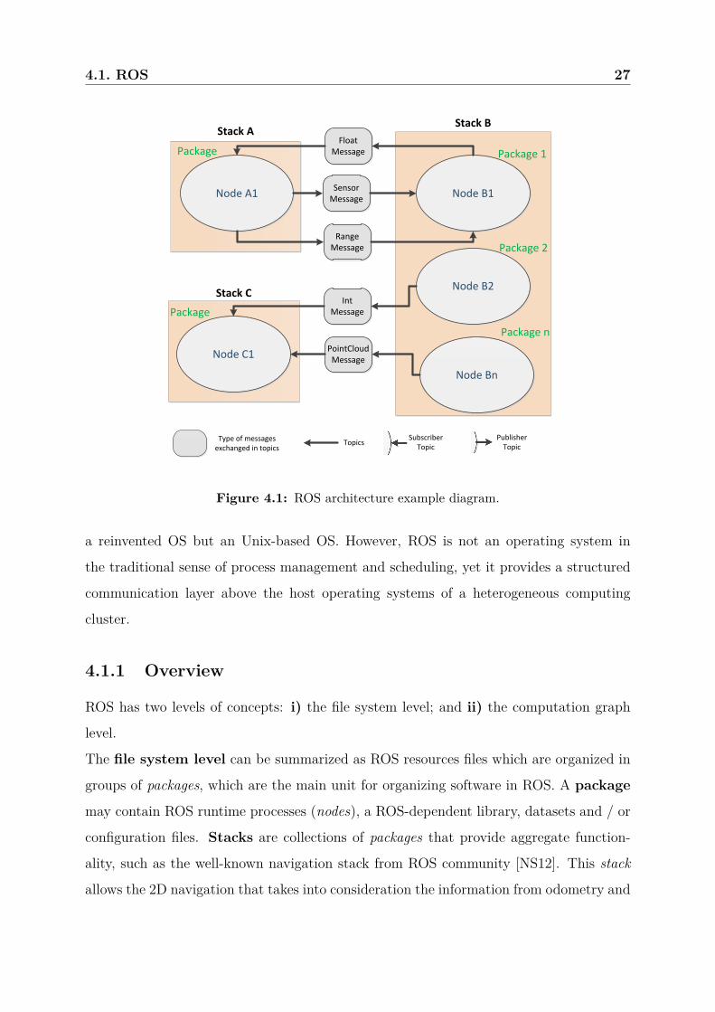
This chapter presented a general overview of ROS (Robot Operating System), as well as a
full description of the two developed drivers. Further more, the potentialities and features
of the ROS drivers have been discussed. Chapter 5 presents the experimental results to
evaluate both the TraxBot platform and the ROS drivers.
Chapter 5
Results and Discussion
In order to experimentally evaluate the herein proposed platform, as well as the ROS
drivers, some experiments were conducted on a laboratory scenario, using both real and
virtual TraxBot platforms using stageros [SS12], which provides essential options like the
information about the ground truth pose and the odometry of virtual robots. These
robots are controlled with velocity commands. Other tests were performed to evaluate
the sensing system and the platform autonomy.
Firstly, the odometry of the robot is analyzed. This is followed by an accuracy analysis
of the sensing information provided by two lateral ultrasonic sonars mounted on top of
the robot, which are compared with a range laser sensor. Subsequently, an analysis of the
robot’s power consumption is done.
A more complex experiment with three sonars mounted on top of the robot is conducted to
address obstacle avoidance performance, as well as interaction between real and simulated
robots, tele-operation test was also performed to validate de potentialities of the ROS
driver and the flexibility to integrate several control devices. Finally, the communication
delays between the modules of the system were analyzed for both drivers.
5.1 Odometry
To evaluate the TraxBot odometry, a square trajectory with one-meter of side length was
performed, in both clockwise (CW) and counter-clockwise (CCW) directions. This test is
extremely challenging due to the fact that the robot always turns in the same direction,
40
5.2. Sensing and Mapping 41
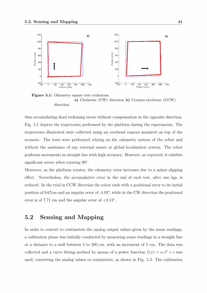
Figure 5.1: Odometry square test evaluation.a) Clockwise (CW) direction b) Counter-clockwise (CCW)
direction.
thus accumulating dead reckoning errors without compensation in the opposite direction.
Fig. 5.1 depicts the trajectories performed by the platform during the experiments. The
trajectories illustrated were collected using an overhead camera mounted on top of the
scenario. The tests were performed relying on the odometry system of the robot and
without the assistance of any external sensor or global localization system. The robot
performs movements in straight line with high accuracy. However, as expected, it exhibits
significant errors when rotating 90°.
Moreover, as the platform rotates, the odometry error increases due to a minor slipping
effect. Nevertheless, the accumulative error in the end of each test, after one lap, is
reduced. In the trial in CCW direction the robot ends with a positional error to its initial
position of 9.67cm and an angular error of -4.93°, while in the CW direction the positional
error is of 7.71 cm and the angular error of +2.13°.
5.2 Sensing and Mapping
In order to convert to centimeters the analog output values given by the sonar readings,
a calibration phase was initially conducted by measuring sonar readings in a straight line
at a distance to a wall between 5 to 200 cm, with an increment of 5 cm. The data was
collected and a curve fitting method by means of a power function f(x) = a.xb + c was
used, converting the analog values to centimeters, as shown in Fig. 5.2. The calibration
5.2. Sensing and Mapping 42
Figure 5.2: Sonar calibration.
function obtained, with the sensor readings (s) as input, was:
f(s) = 1, 1767s0,94657 − 0, 3759
with R2 : 0, 9992.
Note that R2 (or R-square) is a fraction between 0.0 and 1.0, which has no units and
quantifies goodness of fit. Higher values indicate that the model fits the data better
[PR12].
The TraxBot platform was temporarily equipped with a laser range finder (LFR) to
compare its performance against the native ultrasonic range sonars on a mapping task
[RDC05] and to show the flexibility of integrating new sensors in the robot by means of
ROS driver. The Hokuyo URG-04LX is a LRF classified as an Amplitude Modulated
Continuous Wave (AMCW) sensor [KTC+09]. The laser emits an infrared beam and a
rotating mirror changes the beam’s direction. The rotating mirror sweeps the laser beam
horizontally over a range of 240°, with an angular resolution of 0.36°. As the mirror
rotates at about 600 rpm, the scan rate is about 100 msec. The LRF has a quoted range
between 20 and 4095 mm. The quoted measurement error is ±10 mm for distances of less
than 1 m. For greater distances, the error is quoted as ±2%.
In order to test the sonars performance, a scenario with 2 m by 1.6 m in L shape was built,
with a constant width of 1 m and 0.5 m of height (Fig. 5.3). To perform this test, only
two lateral sonars placed at 45 degrees were used, since the goal of this test is to evaluate
the accuracy of sonars by mapping the scenario based on the combination of odometry
5.3. Power Consumption 43
Figure 5.3: Mapping test. a) Sonars b) Laser.
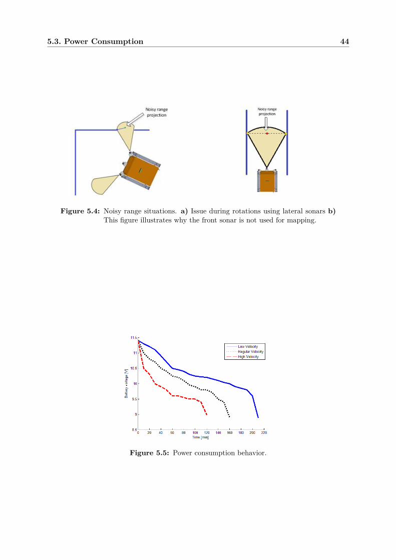
information and sonars readings. The front sonar is usually used for reactive avoidance of
obstacles, given that in mapping situations the projection of walls and obstacles detected
by the cone of the sonar will always be placed in front of the robot, which is highly
unreliable in most situations, as shown for example in Fig. 5.4b. In this test, the robot
movement relies solely on odometry. In Fig. 5.3a it can be seen in the first rectilinear
motion, that the sonars readings are stable (red dots) and coincident with the ground
truth scenario limits (blue line). Green dots represent the midpoint of sonars acoustic
beam.
Some issues arise when there is a rotation of 90 degrees, because the sonar beam cone has
an opening of approximately 36 degrees, thus presenting a loss of resolution, as illustrated
in Fig. 5.4a. In the case of Fig. 5.3b, the Hokuyo range laser sensor was used to perform
the same test. The opening of the laser was set to 180 degrees with a rate of 512 samples
per reading. It is possible to observe some discrepancy in some readings especially at the
end of the movement due the odometry position error accumulated during motion.
This test shows the possibility of integrating more sensors in the TraxBot platform, by
adding, in this case, the hokuyo node in the ROS network.
5.3 Power Consumption
In order to analyze the TraxBot’s power consumption, non-stop circular trajectories stress
tests were performed, at different velocities: Firstly tested at low velocity of 50mm/s,
5.3. Power Consumption 44
Figure 5.4: Noisy range situations. a) Issue during rotations using lateral sonars b)This figure illustrates why the front sonar is not used for mapping.
Figure 5.5: Power consumption behavior.
5.4. ROS Driver Test 45
Figure 5.6: Driver Test. a) Real step test b) Stage simulation.
then at a regular velocity of 100mm/s and finally at a high velocity of 200mm/s. Fig.
5.5 demonstrates the remaining energy of batteries until they reach a minimum working
voltage of approximately 9 V, for the 3 different velocities tested. As expected with the
variation of speeds, it is possible to observe in the figure that the running time decreases
as speed increases.
The results show that the robot is able to operate continuously for 2-3 hours, depending
on the speed profiles.
5.4 ROS Driver Test
5.4.1 Point-to-point Motion
A ROS driver test that consists in performing a step-like trajectory on a grid map of
400×400mm is shown in Fig. 5.6. In this “step test”, a standalone point-to-point navi-
gation algorithm was adopted, using x, y and theta position commands, retrieving data
from sonars and controlling the robot reactively. Two boxes with different dimensions
were added to the map as reference points. The main goal of the experiment is to test
the connectivity between distinct nodes of the network.
A network composed by two machines was used for distributing the processing load, re-
lieving the eeePC notebook, and replicating the experiment simultaneously in the Stage
simulator. ROS master (roscore) and stageros node ran in a desktop computer and the
eeePC was placed on top of TraxBot running the ROS driver (TraxBot_Driver) and the
algorithm node (TraxBot_DriverTest). As it may be observed in Fig. 5.7 (combined with
5.4. ROS Driver Test 46
Figure 5.7: TraxBot teleoperation.
Figure 5.8: Driver Test. a) Two robots with reactive navigation b) Mixed real andvirtual robots.
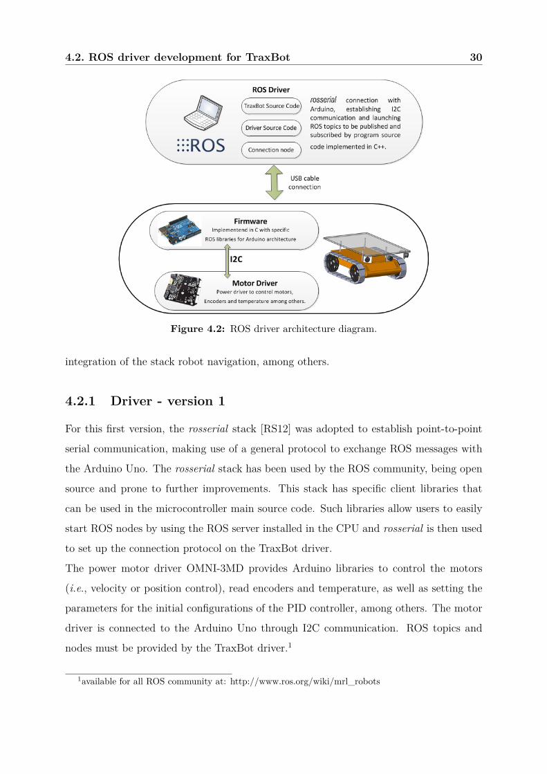
Fig. 4.3), all nodes operate in the same network and communicate through publication
and subscription to topics. While doing the “step test”, the TraxBot updates the odome-
try topic in real-time, which is subscribed by the stage node, processing the messages and
replicating the moves in the virtual world using a virtual robot (on the desktop screen),
as shown in Fig. 5.6b. The delay of this whole process is less than one second.
5.4.2 Mixed virtual and real robots teams
In this experimental trial, two TraxBots were deployed in a bounded laboratory arena
running a reactive wandering algorithm as illustrated by Fig. 5.8a. This test was con-
ducted to verify the coordination between multiple robots. In this case, a mixed team of
real and virtual robots was used to demonstrate the ideas presented in section 4.2.3. The
two real TraxBots were replicated in Stage (Fig. 5.8b), and an extra virtual TraxBot,
with exactly the same reactive algorithm, was added. This can be seen as an interesting
5.4. ROS Driver Test 47
Figure 5.9: TraxBot teleoperation devices.
feature for programmers, since with minor adjustments it is possible to use the same code
for either real or virtual robots. The blue beams in front of the robots correspond to real
scale range readings of 3 ultrasonic sonars installed in the TraxBot platform. All three
robots were able to coordinate themselves in the environment without colliding to each
other through reactive behavior, as shown in the video of the experiments.
5.4.3 Teleoperation
In this test, a node to teleoperate the TraxBot was developed. With teleoperation, one
can drive the robot using external remote control; e.g., a joystick or a keyboard. In the
case of a joystick like the wiimote or the PS3 controller (Fig. 5.9), since they operate via
a wireless technology; i.e., Bluetooth, the teleoperation node runs in the eeePC netbook,
which is an advantage over using the keyboard, given that this option assumes a static
operator controlling the robot, running the ROS teleoperation node in another computer,
which is connected over the ROS network with the eeePC netbook.
The teleoperation node subscribes to topics which have the information of the joystick
state and assigns functions for each pressed button, publishing then velocity commands,
which are interpreted by the TraxBot driver, resulting on motor commands. In the key-
board case, it is not necessary to subscribe to topics with the keyboard state, because the
teleoperation node uses standard C++ libraries to detect which keys are being pressed.