Size Current model [kg] Reduction rate [%] CRA1 [kg] 30 50 63 80 100 0.3 1.5 2.5 4.3 8.5 10 13 12 10 14 0.27 1.3 2.2 3.9 7.3 Mounting interchangeable with the current model Current model Mounting bracket Auto switch can be mounted from the front. Width reduced by up to 14 mm Mountable on 2 surfaces. Weight is reduced by up to 14 %. Size: 30, 50, 63, 80, 100 Size: 30, 50, 63, 80, 100 Standard type Angle adjustable type 30 50 to 100 30 50 to 100 90°, 180° 90°, 180°, 100°, 190° 90°, 180° 90°, 180°, 100°, 190° 90°, 180°, 100°, 190° 90°, 180°, 100°, 190° Size: 50, 63, 80, 100 Size: 50, 63, 80, 100 Compact auto switch ¡Lightweight body by changing the body and the cover shape. Rotating angle 50 to 100 50 to 100 Rotating angle Compact auto switches are mountable. (D-M9) Space saving by changing the auto switch rail mounting to groove mounting. ¡Auto switch can be mounted from the front at any position on the mounting groove. ¡Auto switch can be mounted after installation or when installation condition is changed. Rotary Actuator Ø 30, Ø 50, Ø 63, Ø 80, Ø 100 CAT.EUS20-232C-UK Series CRA1 New New RoHS Mo Mo Mou Mou Mo Mou Mou Mou Mou Mou Mo Mou Mou Mo Mou Mou Mou Mou Mou Mo Mou Mou Mou Mou Mou u ou ou ou ou u u ounti nti nti n nti nti nti nti nti nti nti nti nti nti nti nt nti nti t nti nti nt nti t nti ti ting n n ng ng ng ng ng ng ng ng ng ng ng ng ng ng ng n ng ng ng ng g ng n ng ng ng b b b b b b bra bra bra bra bra bra bra bra bra b bra br bra bra bra bra bra bra bra bra bracke ck ck ck ck ck cke cke cke cke cke cke cke cke ck ck cke ck ck t t uto switch can be mounted from the front. ut uto to sw sw wit itc tc h n b be m o nte d f fro ro m t h e fr fro ro nt nt . surface s u r rf fa c e es s. Weight is reduced by up to %. Auto switch can be mounted from the front at any position on the mounting groove. Auto switch can be mounted after installation or when installation condition is changed.
Transcript
Size Current model [kg] Reduction rate [%]CRA1 [kg]
30506380
100
0.3
1.5
2.5
4.3
8.5
10
13
12
10
14
0.27
1.3
2.2
3.9
7.3
Mounting interchangeable with the current model
Current model
Mounting bracket
Auto switch can be mounted from the front.
Width reduced byup to 14 mm
Mountable on 2 surfaces.
Weight is reduced by up to 14 %.Size: 30, 50, 63, 80, 100Size: 30, 50, 63, 80, 100
uto switch can be mounted from the front.ututoto swswwititctch n bbe mo nted ffrorom the frfrorontnt.
surfacesurrffaceess.
Weight is reduced by up to %.
Auto switch can be mounted from the front at any position on the mounting groove.
Auto switch can be mounted after installation or when installation condition is changed.
Standard type
Auto switch
Auto switches can be mounted in two rows.
Auto switches can be mounted in two rows.
Auto switches can be mounted in two rows.
With cushion valve retaining ring
Port
Slider Tube gasket
Piston seal Spring pin
Cushion seal (New)Repla
cem
ent
parts
Compact auto switches are mountable.Solid state auto switch
D-M9D-M9 W
Reed auto switchD-A9
Cushion seal is replaceable. Rotating angleCushion seal has been made replaceable.(Not possible for current model. Cushion seal only)
Interchangeable with current model
Size 30
90
180100
180
90
Size 30
Size 30
Size 50 to 100
Size 50 to 100
Mountable on 2 surfaces.
Cushion valve cannot be mounted on the air-hydro type.
Easy adjustment of cushion valveCushion valve shape is changed so it can be adjusted using a hexagon wrench only.No protrusion from the body.Retaining ring is used to prevent drop-out.
Auto switch
190
Exterior dimension, shaft diameter, and mounting dimension are interchangeable with current model.
Port, cushion valve and auto switch are on the same surface. Easy to handle.
Double shaft (round shaft, with four chamfers):CRA1BJ
Single round shaft:CRA1BT
Double shaft with key:CRA1BY
Single shaft with four chamfers:CRA1BX
Standard: 8 typesCu
rren
tm
od
el
∗ Single round shaft, double shaft (round shaft, with four chamfers), double round shaft are made to order.
Mounting suitable for operating conditions is possible.Foot bracket can be mounted at a desired position. (Foot bracket is included in the rotary actuator at shipment.)
Back sidePort sideShaft sideBottom side
Angle can be adjusted to an appropriatelevel suitable for applications.
Angle can be adjusted to a desired levelin a range of up to 90°.
Rotation range of keyway 180°
Rotation range of keyway 90°Rotation range of keyway 90°
Adjusting directionAdjusting direction
Angle adjustable type
¡Shaft type can be selected to suit the specification.¡Part number is assigned for shaft types <single round shaft, double shaft (round shaft, with four chamfers), double round shaft>.
Operating temperature Heat resistant 100 °C -X 7 � � � � �
Both sides angle adjustable -X10 � � � �
One side angle adjustable, One side with cushion -X11 � � � �
Fluororubber seal -X16 � � � � �
3
�Rotary Actuator Series CRA1How to Order ······················································································ Page 5Specifications ····················································································· Page 6Dimensions ························································································· Page 7Construction ····················································································· Page 13
�Rotary Actuator: Angle Adjustable Type Series CRA1��U How to Order ···················································································· Page 15Specifications ··················································································· Page 16Dimensions ······················································································· Page 17Construction ····················································································· Page 18
Shaft pattern sequencing 1 -XA1 to -XA24 ························· Page 23 Shaft pattern sequencing 2 -XA33 to -XA59 ······················· Page 27
How to Order ················································································· Page 32 qReversed shaft -XC7 ······························································ Page 33 wChange of rotation range -XC8 to -XC11 ······························ Page 33 eChanged to fluorine grease -XC30 ······································· Page 33 rChange of rotation range and shaft rotation direction -XC31 to XC36 ········ Page 34 tChange of rotation range and angle adjusting direction -XC37 to XC42 ····· Page 35 yChange of rotation range and angle adjusting direction -XC43 to XC46 ····· Page 36 uChange of rotation range and angle adjusting direction (Angle adjusting screw is equipped on the left.) -XC47 to XC52 ···· Page 37 iChange of rotation range and angle adjusting direction (Angle adjusting screw is equipped on the left.) -XC53 to XC58 ···· Page 38 oChange of port location (Mounting location of the cover is changed.) -XC59 to XC61 ···· Page 39 !0One side air-hydro, One side air -XC63, -XC64 ··················· Page 39 !1Stainless steel shaft/Bolt/Parallel key -X6 ······························ Page 40 !2Heat resistant -X7 ·································································· Page 40 !3Both sides angle adjustable -X10 ·········································· Page 40 !4One side angle adjustable, One side with cushion -X11 ········ Page 41 !5Fluororubber seal -X16 ·························································· Page 41 Made to Order/-X6 to -X16 ·························································· Page 42
Specific Product Precautions ················································· Page 43
Made to Order
Simple specials
C O N T E N T SRotary Actuator Series CRA1
4
Auto
Swi
tch
Moun
ting
Sim
ple
Spe
cial
sM
ade
to O
rder
CR
A1�
�U
CR
A1
Rotary Actuator
Series CRA1Rack & Pinion Type/Size: 30, 50, 63, 80, 100
How to Order
Applicable Auto Switches /Refer to the WEB catalogue or the Auto Switch Guide for further information on auto switches.
Type Special functionElectrical
entry
Indica
tor lig
ht
Wiring(Output)
Load voltage Auto switch model Lead wire length [m]Pre-wiredconnector
Applicable loadDC AC Perpendicular In-line
0.5(—)
1(M)
3(L)
5(Z)
So
lid s
tate
au
to s
wit
ch
——
Grommet Yes
3-wire (NPN)
24 V
5 V, 12 V
—
M9NV M9N � � � � �IC circuit
Relay,PLC
3-wire (PNP) M9PV M9P � � � � �
2-wire 12 V M9BV M9B � � � � � —
Diagnosis indication(2-color indication)
3-wire (NPN)5 V, 12 V
M9NWV M9NW � � � � �IC circuit
3-wire (PNP) M9PWV M9PW � � � � �
2-wire 12 V M9BWV M9BW � � � � � —
Water resistant(2-color indication)
3-wire (NPN)5 V, 12 V
M9NAV∗1 M9NA∗1 � � � � �IC circuit
3-wire (PNP) M9PAV∗1 M9PA∗1 � � � � �
2-wire 12 V M9BAV∗1 M9BA∗1 � � � � � —
Reed
auto
switc
h
—— GrommetYes
3-wire(NPN equivalent)
— 5 V — A96V A96 � — � — — IC circuit —
2-wire 24 V 12 V100 V A93V∗2 A93 � � � � — — Relay,
PLCNo 100 V or less A90V A90 � — � — — IC circuit
∗1 Although it is possible to mount water resistant type auto switches, note that the rotary actuator itself is not of water resistant construction.∗2 1 m type lead wire is only applicable to D-A93.
∗ Lead wire length symbols: 0.5 m ·················· — (Example) M9NW 1 m ·················· M (Example) M9NWM 3 m ·················· L (Example) M9NWL 5 m ·················· Z (Example) M9NWZ∗ Auto switches marked with “�” are produced upon receipt of order.∗ Auto switches are shipped together, (but not assembled).
Refer to the WEB catalogue or the Auto Switch Guide for detailed solid state auto switches with pre-wired connectors.
Built-in magnet
MountingB Basic type
L Note 1, 2) Foot type
F Note 3) Flange type
Note 1) For foot bracket and part number, refer to page 6.
Note 2) Foot bracket is included in the same package, (but not assembled).
Note 3) Except size 30.
Shaft typeS Single shaft
W Double shaft
X Single shaft with four chamfers
Y Double shaft with key
Z Double shaft with four chamfers
T Single round shaft
J Double shaft (round shaft, with four chamfers)
K Double round shaft
Note 1) Flange type is not available for T, J, K. Note 2) T, J, K are made to order.
Number of auto switches— 2 pcs.
S 1 pc.
Note) Up to two auto switches are mountable.
Type— Pneumatic
H Note) Air-hydro
Note) Except size 30. Refer to page 43 for handling precautions.
Auto switch
— Without auto switch(Built-in magnet)
Note) For applicable auto switch model, refer to the table below.
Air cushion— None
C Note) With air cushion
Note) Except air-hydro type.
Rotating angle90 90°
180 180°100 Note) 100°190 Note) 190°
Note) Except size 30
Size30506380
100
Port typeSize 30 50 63 80 100
—M thread M5 — — — —
Rc —
1/8 1/8 1/4 3/8TF G —
TN NPT —
TT NPTF —
With auto switch B SCDRA1 50 90 M9BWZ
CRA1 B S 50 90 Z
Made to OrderRefer to page 6.
RoHS
5
Key
Rotation range of keyway 180°+4°
0
Rotation range of keyway 190°+4°
0
+4°
0+4°
0
Rotation range of key
way 1
00°
Rotation range of ke
yway
90°
A port B port
A port B port
Key
Angle
adjus
tmen
t rang
e 3°
Angle adjustment range 3°
Angle
adjus
tmen
t rang
e 3°
Angle
adjus
tmen
t rang
e 3°
Rotation range of ke
yway
90°
Rotation range of keyw
ay 1
80°
Made to Order(For details, refer to pages 22 to 42.)
Symbol Description Applicable shaft type-XA1 to -XA24 Shaft pattern sequencing! S, W, Y-XA33 to -XA59 Shaft pattern sequencing@ X, Z, T, J, K
-XC7 Reversed shaft S, W, X, T, J-XC8 to -XC11 Change of rotation range S, W, Y
-XC30 Changed to fl uorine grease
S, W, X, Y,Z, T, J, K
-XC31 to -XC36 Change of rotation range and shaft rotation direction
S, W, Y
-XC59 to -XC61 Change of port directionS, W, X, Y, Z, T, J, K
-XC63, -XC64 One side air-hydro, One side air
S, W, X, Y, Z, T, J, K
-X6 Stainless steel shaft/ bolt, etc.
S, W, X, Y, Z, T, J, K
-X7∗ Heat resistant (100 °C)S, W, X, Y, Z, T, J, K
-X16 Fluororubber sealS, W, X, Y, Z, T, J, K
∗ X7: Not available for the built-in magnet type
The shaft rotates clockwise when the pressure is applied from the A port while it rotates counterclockwise when the pressure is applied from the B port.
M5 x 0.8 x 2550 CRA1L50-Y-1Z M8 x 1.25 x 3563 CRA1L63-Y-1Z M10 x 1.5 x 4080 CRA1L80-Y-1Z M12 x 1.75 x 50
100 CRA1L100-Y-1Z M12 x 1.75 x 50
∗ Size 30 does not include collars.∗ Remove the basic type mounting screws and use the mounting screws included in the foot
bracket to secure the foot bracket to the cover. Use the collar as a spacer for the cover counterbore part and secure it together with the foot.
∗ For size 30, be careful not to drop the cover when removing the basic type mounting screws.Additionally, do not mount the foot bracket with the pressure applied to the port.
Flange type
Basic type
Foot type
Symbol
Rotation Range of Keyway
Size: 50 to 100
Size: 30
6
Rotary ActuatorRack & Pinion Type Series CRA1
Auto
Swi
tch
Moun
ting
Sim
ple
Spe
cial
sM
ade
to O
rder
CR
A1�
�U
CR
A1
Dimensions/Basic Type: C�RA1B�
Size: 30Single shaft: C�RA1BS
Double shaft: C�RA1BW
¡Drawing shows the appearance for rotation of 90°.¡Dimensions show pressurisation to B port.¡ Drawing shows that the auto switch is mounted on the side opposite to the port side. (Dimensions with an asterisk mark (*) are not required for actuators
without the auto switch.)∗ ( ) are the dimensions for rotation of 180°.Note) A parallel key is included in the same package, (but not assembled).
�28Auto switch
9
8 x M5 x 0.8 depth 6(Opposite side 4 locations)
5.55.5
9.2
44.
5
44.
5
2 x Cushion valve(Width across flats 1.5)
2 x M5 x 0.8Port size
B portA port
98 (117)/With auto switch84 (103)/Without auto switch
65
25
2
314
22∗
2.2∗
9∗
�405
9
3 0 −0.025
5∗
ø 8g6
ø 16 0 −0.1
ø 7.8 0
−0.2
75
108
�6 0 −0.2
ø 8 (g6)
7
Series CRA1
Dimensions/Basic Type: C�RA1B�
Size: 50/63/80/100Single shaft: C�RA1BS
Double shaft: C�RA1BW
Note) Other dimensions are the same as the single shaft type. [mm]
SizeD
(g6)G M N UU L
50 15 11 20 15 118 14
63 17 13 22 17 139 16
80 20 15 25 20 167 19
100 25 19 30 25 202 24
Ø D is the shaft dimension.
¡Drawing shows the appearance for rotation of 90° and 100°.¡Dimensions show pressurization to B port.¡Drawing shows the auto switch mounted on the port side.∗ ( ) are the dimensions for rotation of 180° and 190°. [mm]
SizePortsize A B C
D(g6)
DD(h9)
F H J KWith auto switch
Without auto
switch U W BA BB BC �CA
�CB
Note)Key
dimensionsS SB SC SD SE S b L1
50 1/8 62 48 46 15 25 2.5 36M8 × 1.25depth 8
5156
(189)1.5 5 14.5 33
144(177)
98 17 17 8.5 6 9.5 7.5 5 0 −0.030 25
63 1/8 76 60 57 17 30 2.5 41M10 × 1.5depth 12
5175
(213.5)1.5 5 21.5 33
163(201.5)
117 19.5 20 10 7 11 8 6 0 −0.030 30
80 1/4 92 72 70 20 35 3 50M12 × 1.75depth 13
5199
(243)1.5 5 29.5 33
186(230)
142 22.5 23.5 12 8 13 9 6 0 −0.030 40
100 3/8 112 85 85 25 40 4 60M12 × 1.75depth 14
5259
(325)1.5 5 39.5 33
245(311)
172 28 25 12.5 8 14 10 8 0 −0.036 45
Note) A parallel key is included in the same package, (but not assembled).
8 x J (Opposite side 4 locations)
B
W
CA
CB
BC
BB
BA
S
BA
BB
BC
CB
CA
Auto switch
2 x Port size
A port
B port
2 x Cushion valve(Width across flats 3)
�A
�C
SB
SCSE
SD
F
b
ø D (g6)
ø DD (h9)
H
U
L1
K
ø L
0−0
.2
0−0.2
UU
MN
�G
ø D (g6)
8
Rotary ActuatorRack & Pinion Type Series CRA1
Auto
Swi
tch
Moun
ting
Sim
ple
Spe
cial
sM
ade
to O
rder
CR
A1�
�U
CR
A1
Dimensions/Basic Type: C�RA1B�
Size: 30/50/63/80/100Single shaft with four chamfers: C�RA1BX Double shaft with key: C�RA1BY Double shaft with four chamfers: C�RA1BZ
Single round shaft: C�RA1BT Double shaft (round shaft, with four chamfers): C�RA1BJ Double round shaft: C�RA1BK
Note) Other dimensions are the same as the single shaft type. [mm]
Size G H N U L30 6 13 8 53 7.8
50 11 27 15 89 14
63 13 29 17 105 16
80 15 38 20 130 19
100 19 44 25 156 24
Note) Other dimensions are the same as the single shaft type. [mm]
Size H K UU L30 25 3 90 14
50 36 5 134 25
63 41 5 158 30
80 50 5 192 40
100 60 5 232 45
Note) Other dimensions are the same as the single shaft type. [mm]
SizeD
(g6)G H M N U UU L
30 8 6 13 10 8 53 63 7.8
50 15 11 27 20 15 89 109 14
63 17 13 29 22 17 105 127 16
80 20 15 38 25 20 130 155 19
100 25 19 44 30 25 156 186 24
Note) Other dimensions are the same as the single shaft type.
[mm]
SizeD
(g6)H
30 8 25
50 15 36
63 17 41
80 20 50
100 25 60
Note) Other dimensions are the same as the single shaft type. [mm]
SizeD
(g6)H UU
30 8 25 90
50 15 36 134
63 17 41 158
80 20 50 192
100 25 60 232
Note) Other dimensions are the same as the single shaft type. [mm]
SizeD
(g6)G H M N UU L
30 8 6 25 10 8 75 7.8
50 15 11 36 20 15 118 14
63 17 13 41 22 17 139 16
80 20 15 50 25 20 167 19
100 25 19 60 30 25 202 24
ø L
0−0
.2
0−0.1
U
H
N
�G
UU
H
HLK
UU
U
H
N
MN
ø D
ø L
0−0
.2
0−0.1�G
ø L
0−0
.2
0−0.2�G
ø D
H
UU
MN
ø D
H
ø D
ø L
0−0
.2
0−0.2�G
UU
HH
ø D
9
Series CRA1
138(157)/With auto switch124(143)/Without auto switch
158(177)/With auto switch144(163)/Without auto switch
B portA port
Foot bracket
Auto switch
4 x ø 6(Mounting hole)
69
24
3.2
4028
44 44
¡Drawing shows the appearance for rotation of 90°.¡Dimensions show pressurisation to B port.¡Drawing shows that the auto switch is mounted on the side opposite to the port side.∗ ( ) are the dimensions for rotation of 180°.
Dimensions/Foot Type: C�RA1L�
Size: 30
10
Rotary ActuatorRack & Pinion Type Series CRA1
Auto
Swi
tch
Moun
ting
Sim
ple
Spe
cial
sM
ade
to O
rder
CR
A1�
�U
CR
A1
LA
LC
LH
LF
LTLD
LE
Foot bracket 4 x ø LB(Mounting hole)
A port B port
¡Drawing shows the appearance for rotation of 90° and 100°.¡Dimensions show pressurisation to B port.¡Drawing shows that the auto switch mounted on the port side.∗ ( ) are the dimensions for rotation of 180° and 190°.
Note) Other dimensions are the same as the basic type. [mm]
Size LA LB LCWith auto switch Without auto switch
LF LH LTLD LE LD LE
50 62 9 44212
(245)236
(269)200
(233)224
(257)41 108 4.5
63 76 11 55247
(285.5)275
(313.5)235
(273.5)263
(301.5)48 127 5
80 92 13 67287
(331)329
(373)274
(318)316
(360)58 154 6
100 112 13 87347
(413)389
(455)333
(399)375
(441)73.5 189.5 6
Dimensions/Foot Type: C�RA1L�
Size: 50/63/80/100
11
Series CRA1
FY
ZY
ZXFX
U
H
FT
F
2 x MM
4 x ø FD(Mounting hole)
UU
U
HN
U
HN
UU
U
H
UU
U
HN
N
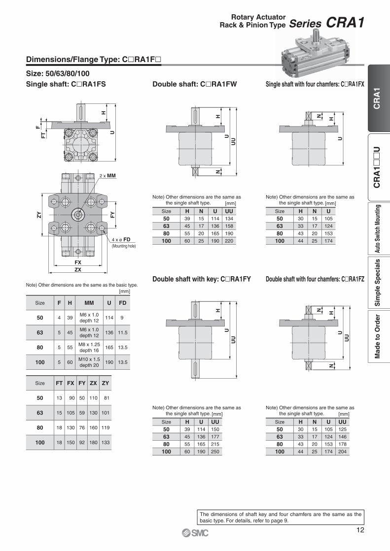
The dimensions of shaft key and four chamfers are the same as the basic type. For details, refer to page 9.
Single shaft: C�RA1FS Double shaft: C�RA1FW Single shaft with four chamfers: C�RA1FX
Dimensions/Flange Type: C�RA1F�
Size: 50/63/80/100gle shaft with four chamfers: C�RA1
Double shaft with key: C�RA1FY Double shaft with four chamfers: C�RA1FZNote) Other dimensions are the same as the basic type. [mm]
Size F H MM U FD
50 4 39M6 x 1.0depth 12
114 9
63 5 45M6 x 1.0depth 12
136 11.5
80 5 55M8 x 1.25depth 16
165 13.5
100 5 60M10 x 1.5depth 20
190 13.5
Size FT FX FY ZX ZY
50 13 90 50 110 81
63 15 105 59 130 101
80 18 130 76 160 119
100 18 150 92 180 133
Note) Other dimensions are the same as the single shaft type. [mm]
Size H N U UU50 39 15 114 134
63 45 17 136 158
80 55 20 165 190
100 60 25 190 220
Note) Other dimensions are the same as the single shaft type. [mm]
Size H U UU50 39 114 150
63 45 136 177
80 55 165 215
100 60 190 250
Note) Other dimensions are the same as the single shaft type. [mm]
Size H N U50 30 15 105
63 33 17 124
80 43 20 153
100 44 25 174
Note) Other dimensions are the same as the single shaft type. [mm]
Size H N U UU50 30 15 105 125
63 33 17 124 146
80 43 20 153 178
100 44 25 174 204
12
Rotary ActuatorRack & Pinion Type Series CRA1
Auto
Swi
tch
Moun
ting
Sim
ple
Spe
cial
sM
ade
to O
rder
CR
A1�
�U
CR
A1
@9 !3
e t !4!1 i!0!2 qwor
y u@8
@8@7
!7!6 !8@0
@6
@4
@2
@5
!5
!9 @1 @3
Replacement Parts
SizePart no.
Without air cushion With air cushion Air-hydroNote 2)
Corresponding partsu, o, !0, !3 are included as a set.
u, o, !0, !3, @1 are included as a set.
—
Note 1) When ordering replacement parts, write “1” for one set of the parts per actuator.Note 2) Replacement parts for different rotation angles are set.A grease pack (10 g) is included.If an additional grease pack is needed, order with the following part number.Grease pack part number: GR-S-010 (10 g)
Construction: Size 30
With air cushion Without air cushion With auto switch
Without air cushion
No. Description Material Note1 Body Aluminium alloy Anodised2 Right cover Aluminium alloy Metallic coating3 Left cover Aluminium alloy Metallic coating4 Piston Aluminium alloy5 Shaft Alloy steel6 Rack Carbon steel Nitrided7 Slider Resin8 Bearing retainer Zinc alloy Chromated9 Tube gasket NBR
10 Piston seal NBR11 Bearing High carbon chrome bearing steel12 Hexagon socket head cap screw with washer Alloy steel Zinc chromated13 Spring pin Steel Zinc chromated14 Parallel key Carbon steel15 Cross-recessed pan head tapping screw Steel Zinc chromated16 Auto switch —17 Magnet —18 Switch spacer Resin19 Cushion ring Aluminium alloy Anodised20 Cushion valve Steel Nickel plated21 Cushion seal Urethane22 O-ring NBR
Without air cushion With air cushion Air-hydro50 P694020-20 P694020-21 P694020-2363 P694030-20 P694030-21 P694030-2380 P694040-20 P694040-21 P694040-23
100 P694050-20 P694050-21 P694050-23Corresponding
partsu, o, !0, !3 are included as a set.
u, o, !0, !3, @3 are included as a set.
u, o, !0, !3 are included as a set.
Note) When ordering replacement parts, write “1” for one set of the parts per actuator.A grease pack (10 g) is included.If an additional grease pack is needed, order with the following part number.Grease pack part number: GR-S-010 (10 g)
Construction: Size 50 to 100
With air cushion Without air cushion With auto switch
Without air cushion
No. Description Material Note1 Body Aluminium alloy Anodised2 Right cover Aluminium alloy Metallic coating3 Left cover Aluminium alloy Metallic coating4 Piston Aluminium alloy5 Shaft Alloy steel6 Rack Carbon steel Nitrided7 Slider Resin8 Bearing retainer Aluminium alloy Chromated9 Tube gasket NBR
10 Piston seal NBR11 Bearing High carbon chrome bearing steel12 Hexagon socket head cap screw with washer Alloy steel Zinc chromated13 Spring pin Steel Zinc chromated14 Parallel key Carbon steel15 Connecting screw Carbon steel Zinc chromated16 Cross-recessed pan head tapping screw Steel Zinc chromated17 Wear ring Resin18 Auto switch —19 Magnet —20 Switch spacer Resin21 Cushion ring Aluminium alloy Anodised22 Cushion valve Steel Zinc chromated23 Cushion seal Urethane24 O-ring NBR25 Seal retainer Steel26 Retaining ring Steel
Component Parts
14
Rotary ActuatorRack & Pinion Type Series CRA1
Auto
Swi
tch
Moun
ting
Sim
ple
Spe
cial
sM
ade
to O
rder
CR
A1�
�U
CR
A1
Built-in magnet
Angle adjustable type
Auto switch
— Without auto switch(Built-in magnet)
∗ For applicable auto switch model, refer to the table below.
Rotating angle90 90°180 180°100 100°190 190°
Size506380
100
Port typeSize 50 63 80 100
— Rc
1/8 1/4 3/8TF G
TN NPT
TT NPTF
With auto switch CDRA1
CRA1
Rotary Actuator: Angle Adjustable Type(Angle adjustment mechanism is provided as standard.)
Series CRA1��U Rack & Pinion Type/Size: 50, 63, 80, 100
How to Order
Made to OrderRefer to page 16.
MountingB Basic type
L Note 1, 2) Foot type
F Flange type
Note 1) For foot bracket and part number, refer to page 16.
Note 2) Foot bracket is included in the same package, (but not assembled).
Shaft typeS Single shaft
W Double shaft
X Single shaft with four chamfers
Y Double shaft with key
Z Double shaft with four chamfers
T Single round shaft
J Double shaft (round shaft, with four chamfers)
K Double round shaft
∗ Flange type is not available for T, J, K.∗ T, J, K are made to order.
Number of auto switches— 2 pcs.
S 1 pc.
Note) Up to two auto switches are mountable.
Applicable Auto Switches /Refer to the WEB catalogue or the Auto Switch Guide for further information on auto switches.
Type Special functionElectrical
entry
Indica
tor lig
ht
Wiring(Output)
Load voltage Auto switch model Lead wire length [m]Pre-wiredconnector
Applicable loadDC AC Perpendicular In-line
0.5(—)
1(M)
3(L)
5(Z)
So
lid s
tate
au
to s
wit
ch
——
Grommet Yes
3-wire (NPN)
24 V
5 V, 12 V
—
M9NV M9N � � � � �IC circuit
Relay,PLC
3-wire (PNP) M9PV M9P � � � � �
2-wire 12 V M9BV M9B � � � � � —
Diagnosis indication(2-color indication)
3-wire (NPN)5 V, 12 V
M9NWV M9NW � � � � �IC circuit
3-wire (PNP) M9PWV M9PW � � � � �
2-wire 12 V M9BWV M9BW � � � � � —
Water resistant(2-color indication)
3-wire (NPN)5 V, 12 V
M9NAV∗1 M9NA∗1 � � � � �IC circuit
3-wire (PNP) M9PAV∗1 M9PA∗1 � � � � �
2-wire 12 V M9BAV∗1 M9BA∗1 � � � � � —
Reed
auto
switc
h
—— GrommetYes
3-wire(NPN equivalent)
— 5 V — A96V A96 � — � — — IC circuit —
2-wire 24 V 12 V100 V A93V∗2 A93 � � � � — — Relay,
PLCNo 100 V or less A90V A90 � — � — — IC circuit
∗1 Although it is possible to mount water resistant type auto switches, note that the rotary actuator itself is not of water resistant construction.∗2 1 m type lead wire is only applicable to D-A93.
∗ Lead wire length symbols: 0.5 m ·················· — (Example) M9NW 1 m ·················· M (Example) M9NWM 3 m ·················· L (Example) M9NWL 5 m ·················· Z (Example) M9NWZ∗ Auto switches marked with “�” are produced upon receipt of order.∗ Auto switches are shipped together, (but not assembled).
Refer to the WEB catalogue or Auto Switch Guide for detailed solid state auto switches with pre-wired connectors.
B S 50 90 M9BW
B S 50 90
U Z
U Z
RoHS
, ,,,,,,,,
15
Specifi cations
Type Pneumatic
Size 50 63 80 100Fluid Air (Non-lube)
Max. operating pressure 1.0 MPa
Min. operating pressure 0.1 MPa
Ambient and fl uid temperature 0 to 60 °C (No freezing)
Cushion None
Backlash Within 1°Angle adjustment range Max. 90°
∗ For details about the effective torque, allowable kinetic energy, and adjustable range of rotation time safe in operation, refer to page 6.
Made to Order (For details, refer to pages 22 to 42.)
Symbol Description Applicable shaft type
-XA1 to -XA24 Shaft pattern sequencing! S, W, Y
-XA33 to -XA59 Shaft pattern sequencing@ X, Z, T, J, K
-XC7 Reversed shaft S, W, X, T, J
-XC30 Changed to fl uorine grease
S, W, X, Y Z, T, J, K
-XC37 to -XC46 Change of rotation range and angle adjusting direction
S, W, Y
-XC47 to -XC58
Change of rotation range and angle adjusting direction(Angle adjusting screw is equipped on the left.)
S, W, Y
-XC59 to -XC61 Change of port directionS, W, X, Y Z, T, J, K
-X7∗ Heat resistant type (100 °C)
S, W, X, Y Z, T, J, K
-X16 Fluororubber sealS, W, X, Y Z, T, J, K
-X10 Both sides angle adjustable
S, W, X, Y Z, T, J, K
-X11One side angle adjustable, One side with cushion
S, W, X, Y Z, T, J, K
∗ -X7: Not available for the built-in magnet type.
Weight [kg]
SizeStandard weight Additional weight
90° 180° With auto switch∗ Foot bracket Flange bracket
50 1.4 1.6 0.2 0.3 0.5
63 2.4 2.8 0.4 0.5 0.9
80 4.2 4.7 0.6 0.9 1.5
100 7.8 8.8 0.9 1.2 2.0
∗ With 2 auto switches
Rotation Range of Keyway/Angle Adjustment
The shaft rotates clockwise when the pressure is applied from the A port.The clockwise rotation end position is adjusted using the angle adjusting screw.Note) Take appropriate measures so that no excessive external impact or vibration is applied to
the angle adjusting screw.Failure to do so may cause the angle adjusting screw to become loose or drop.
Adjustment angle per rotation of angle adjusting screwSize 50 63 80 100
∗ Remove the basic type mounting screws and use the mounting screws included in the foot bracket to secure the foot bracket to the cover. Use the collar as a spacer for the cover counterbore part and secure it together with the foot.
Angle adjusting screw
A port B port
Angle adjust
ing
dire
ctio
n
Angle adjusting direction
Rotation range of keyway 190
Rotation range of keyway 180Rotation range
of ke
yway
90
Rotation range
of ke
yway
100
16
Rotary Actuator: Angle Adjustable TypeRack & Pinion Type Series CRA1��U
Auto
Swi
tch
Moun
ting
Sim
ple
Spe
cial
sM
ade
to O
rder
CR
A1�
�U
CR
A1
Dimensions/Basic Type: C�RA1BSU
Size: 50/63/80/100Single shaft: C�RA1BSU
¡Drawing shows the appearance for rotation of 90° and 100°.¡Dimensions show pressurisation to B port.¡Drawing shows the auto switch mounted on the port side.∗ ( ) are the dimensions for rotation of 180° and 190°. [mm]
Size Note 1)
Portsize A B C D
(g6)DD(h9)
F H J KWith auto switch
Without auto
switch U W BA BB BCS SB SC SD SE S
50 1/8 62 48 46 15 25 2.5 36M8 x 1.25depth 8
5156
(189)1.5 5 14.5 33
144(177)
98 17 17 8.5 6
63 1/8 76 60 57 17 30 2.5 41M10 x 1.5depth 12
5175
(213.5)1.5 5 21.5 33
163(201.5)
117 19.5 20 10 7
80 1/4 92 72 70 20 35 3 50M12 x 1.75depth 13
5199
(243)1.5 5 29.5 33
186(230)
142 22.5 23.5 12 8
100 3/8 112 85 85 25 40 4 60M12 x 1.75depth 14
5259
(325)1.5 5 39.5 33
245(311)
172 28 25 12.5 8
Size AU BU CU SU MUKey Note)
dimensions
b L1
50 9.5 6 19 33 M12 x 1.75 5 0 −0.030 25
63 10.5 6 22 35.5 M14 x 2 6 0 −0.030 30
80 12.5 8 24 44 M16 x 2 6 0 −0.030 40
100 14.5 10 30 56 M20 x 2.5 8 0 −0.036 45
Note) A parallel key is included in the same package, (but not assembled).
The dimensions of the shaft type W: Double shaft, X: Single shaft with four chamfers, Y: Double shaft with key, Z: Double shaft with four chamfers, T: Single round shaft, J: Double shaft round shaft, with four chamfers, K: Double round shaft, foot type, and fl ange type are the same as the standard type. For details, refer to pages 9 to 12.
8 x J (Opposite side 4 locations)
B
CU
(Hex
agon
wid
th
acro
ss fl
ats)
W
AU
MU
BBBA
SBA
BB
BC
Auto switch
2 x Port size
B port
A port
SU (Max.)b
KL
1 HU
�C�ASB
SD
SCSE
F
ø DD (h9)
ø D (g6)
BU(Width across flats)
17
Series CRA1��U
Construction
!8 u !4 i !7
e !0 t !1 !6
!9 @3
@6@7 @5
@4
y !5 !2 o r q w
!3 @2 @1 @0
With auto switch
Component PartsNo. Description Material Note
1 Body Aluminium alloy Anodised
2 Right cover Aluminium alloy Metallic coating
3 Left cover Aluminium alloy Metallic coating
4 Right piston Aluminium alloy
5 Left piston Aluminium alloy
6 Shaft Alloy steel
7 Rack Carbon steel Nitrided
8 Slider Resin
9 Bearing retainer Aluminium alloy Chromated
10 Tube gasket NBR
11 Piston seal NBR
12 Bearing High carbon chrome bearing steel
13 Hexagon socket head cap screw with washer Alloy steel Zinc chromated
14 Spring pin Steel Zinc chromated
No. Description Material Note
15 Parallel key Carbon steel
16 Connecting screw Carbon steel Zinc chromated
17 Cross-recessed pan head tapping screw Steel Zinc chromated
18 Wear ring Resin
19 Stopper Carbon steel Zinc chromated
20 Hexagon socket head set screw (fl at point) Alloy steel Zinc chromated
Replacement PartsSize Part no. Corresponding parts
50 P694020-22
i, !0, !1, !4, @2 are included as a set.
63 P694030-22
80 P694040-22
100 P694050-22
Note) When ordering replacement parts, write “1” for one set of the parts per actuator.
A grease pack (10 g) is included.If an additional grease pack is needed, order with the following part number. Grease pack part number: GR-S-010 (10 g)
18
Rotary Actuator: Angle Adjustable TypeRack & Pinion Type Series CRA1��U
Auto
Swi
tch
Moun
ting
Sim
ple
Spe
cial
sM
ade
to O
rder
CR
A1�
�U
CR
A1
Series CRA1Auto Switch Mounting
Auto Switch Proper Mounting Position at Rotation End
Size Rotating angle
D-M9�/M9�VD-M9�W/M9�WVD-M9�A/M9�AV
D-A9�/A9�V
Proper mounting positionA [mm]
Operating rangeθ [°]
Proper mounting positionA [mm]
Operating rangeθ [°]
3090 13
42°9
81°180 22 18
5090 22.5
30°18.5
44°180 39 35
6390 25
28°21
49°180 44.5 40.5
8090 27.5
23°23.5
41°180 49.5 45.5
10090 42.5
15°38.5
29°180 75.5 71.5
∗ Values which include hysteresis are for guideline purposes only, they are not a guarantee (assuming approximately ±30 % dispersion) and may change substantially depending on the ambient environment. Adjust the auto switch after confi rming the operating conditions in the actual setting.
Switch Spacer/Part No.Size 30 50 63 80 100
Switch spacer part no. BMY3-016
∗ The above part number includes one switch spacer.∗ Two switch spacers are included with the product with built-in magnet.
A AA A
A A
Auto switch Auto switch
Connection port
Perpendicular type auto switch
Connection port
Operating range at proper mounting position /2
Operating range of single auto switch
Most sensitive position
Size: 30 Size: 50 to 100
For size 30, only the perpendicular type auto switch can be mounted since two auto switches are mounted in the same switch groove when mounting the switch on the connection port side.
19
Auto Switch Mounting
To fi x the auto switch, hold the switch spacer, and insert into the groove. Make sure that the switch spacer is in the right position or correct the position if necessary, then slide the auto switch in the groove so that it goes into the spacer. Confi rm where the mounting position is, and tighten the auto switch mounting screw using a fl at head screwdriver.
Auto Switch Working Principle
[Pressure is applied from the B port.]The auto switch B is turned ON by the magnet B in the state that the pressure is applied from the B port and the piston B moves to the left side. At this time, the auto switch A turns OFF.
[Pressure is applied from the A port.]When the pressure is applied from the A port, the piston A moves to the right side and the shaft rotates clockwise.The auto switch B turns OFF and the auto switch A is turned ON by the magnet A at the rotation end.
Switch spacer(BMY3-016)
Switch mounting screw (Attached to switch)(M2.5 x 4L)
Flat head watchmakers’ screwdriver (Not attached to switch)
Auto switch BAuto switch A
Magnet B Piston B
A port B port
Auto switch BAuto switch A
Magnet APiston A Shaft
A port B port
Note) When tightening an auto switch mounting screw, use a watchmakers’ screwdriver with a handle of approximately 5 to 6 mm in diameter.Also, tighten with a torque of about 0.1 to 0.15 N·m.As a guide, turn about 90° past the point at which tightening can fi rst be felt.
20
Auto Switch Mounting Series CRA1
Auto
Swi
tch
Moun
ting
Sim
ple
Spe
cial
sM
ade
to O
rder
CR
A1�
�U
CR
A1
21
Shaft pattern sequencing 1 -XA1 to -XA24 ························································ Page 23
Shaft pattern sequencing 2 -XA33 to -XA59 ······················································ Page 27
How to Order ················································································································ Page 32
!4One side angle adjustable, One side with cushion -X11 ······································· Page 41
!5Fluororubber seal -X16 ························································································· Page 41
Made to Order/-X6 to -X16 ························································································· Page 42
Made to Order
Simple specials
C O N T E N T SRotary Actuator Series CRA1
Simple Specials/Made to Order
22
Auto
Swi
tch
Moun
ting
Sim
ple
Spe
cial
sM
ade
to O
rder
CR
A1�
�U
CR
A1
Series CRA1Simple SpecialsShaft shape pattern is dealt with simple made-to-order system. A specifi cation sheet is available for ordering. Please access SMC website, or consult your nearest sales branch.
Symbol
Shaft Pattern Sequencing1 -XA1 to -XA24Applicable shaft type: S, W, Y
How to Order
C RA1 Z XD B S 50 90 M9BW A1 A2 C8 C59
Port typeSize 30 50 63 80 100
—M thread M5 — — — —
Rc —
1/8 1/8 1/4 3/8TF G —
TN NPT —
TT NPTF —
Magnet— None
D Built-in magnet
Size30506380
100
Rotating angle90 90°
180 180°100 Note) 100°190 Note) 190°
Note) Except size 30
Number of auto switches— 2 pcs.
S 1 pc.
Auto switch
— Without auto switch(Built-in magnet)
Note 1) For applicable auto switch model, refer to page 5.
Note 2) Auto switches are shipped together, (but not assembled).
∗ Corresponding shafts type available for combination
Combination Chart of Made to Order
Chart 2. Combination between -XA� and -XC�Symbol Description
Applicable shaft type Applicable size
Combination
S W Y -XA1, 2, 13 to 19 -XA20, 24-XC7 Reversed shaft � � — 50, 63,
80, 100— —
-XC8 to -XC11 Change of rotation range � � � � —
-XC30 Changed to fl uorine grease � � � 30 to 100 � �
-XC31 to -XC36 Change of rotation range and shaft rotation direction � � �
50, 63, 80, 100
� —
-XC37 to -XC46 Change of rotation range and angle adjusting direction � � � � —
-XC47 to -XC58 Change of rotation range and angle adjusting direction(Angle adjusting screw is equipped on the left.) � � � � —
-XC59 to -XC61 Change of port location � � � 30 to 100 � �
-XC63 One side air-hydro, One side air � � � 50, 63, 80, 100
� �
-XC64 One side air-hydro, One side air � � � � �
∗ -XC8 to -XC11 and -XC31 to -XC36 do not include the angle adjustable type.∗ -XC37 to -XC46 and -XC47 to -XC58 are only the angle adjustable type.∗ -XC63 and -XC64 are only the air-hydro type.
Chart 3. Combination between -X� and -XA�Symbol Description
Applicable shaft type Applicable size
Combination
S W X -XA1, 2, 13 to 19 -XA20, 24-X6 Stainless steel shaft/bolt, etc. � � �
30 to 100� �
-X7 Heat resistant (100 °C) � � � � �
-X10 Both sides angle adjustable � � �50 to 100
� �
-X11 One side angle adjustable, One side with cushion � � � � �
-X16 Fluororubber seal � � � 30 to 100 � �
∗ -X10 and -X11 are only the angle adjustable type.
24
Simple Specials Series CRA1
CR
A1
Auto
Swi
tch
Moun
ting
Sim
ple
Spe
cial
sM
ade
to O
rder
CR
A1�
�U
Symbol
Shaft Pattern Sequencing1 -XA1 to -XA17Applicable shaft type: S, W, Y
Additional Reminders1. Enter the dimensions within a range that allows
for additional machining.2. SMC will make appropriate arrangements if no
dimensional, tolerance, or fi nish instructions are given in the diagram.
3. The length of the unthreaded portion is 2 to 3 pitches.
4. Unless specified otherwise, the thread pitch is based on coarse metric threads.
P = Thread pitchM4 x 0.7, M5 x 0.8, M6 x 1, M8 x 1.25, M10 x 1.5
5. Enter the desired fi gures in the portion of the diagram.
6. Chamfer face of the parts machining additionally is C0.5.
Symbol: A2The maximum dimension L2 is, as a rule, twice the thread size.(Example) For M4: L2 = 8· Applicable shaft types: S, W, Y
Machine female threads into the short shaft. Note) Except fl ange type
Symbol: A15 Note) Except fl ange type
A special end is machined onto the short shaft, and a through-hole is drilled into it. Female threads are machined into the through-hole, whose diameter is equivalent to the pilot hole diameter.The maximum dimension L2 is, as a rule, twice the thread size.(Example) For M5: L2 = 10· Applicable shaft types: S, W, Y
Symbol: A13 Shaft through-hole Note) Except fl ange type
Minimum machining diameter for d1 is 0.1.· Applicable shaft types: S, W, Y
[mm]Size d130 Ø 2.550 Ø 4 to Ø 763 Ø 4 to Ø 880 Ø 6.8 to Ø 11100 Ø 6.8 to Ø 13
Symbol: A16 Note) Except fl ange type
A special end is machined onto both the long and short shafts, and a through-hole is drilled into both shafts. Female threads are machined into the through-holes, whose diameter is equivalent to the diameter of the pilot holes.The maximum dimension L1 is, as a rule, twice the thread size.(Example) For M5: L1 = 10·Applicable shaft types: S, W, Y·Equal dimensions are indicated by the same marker.
A special end is machined onto the long shaft, and a through-hole is drilled into it. Female threads are machined into the throughhole, whose diameter is equivalent to the pilot hole diameter.The maximum dimension L1 is, as a rule, twice the thread size.(Example) For M5: L1 = 10· Applicable shaft types: S, W, Y
Machine female threads into the long shaft. Note) Except fl ange type
Q2 = M
L2 +
(3
x P
)
L2 =
d1 = ø
Q1 = M
L1 =
L1
Q1
Q1 = M
L1 =
X =
Q1 = M
L1 +
(3
x P
)
L1 =
Q2 = M
L2 =
25
Series CRA1
Symbol
Shaft Pattern Sequencing1 -XA18 to -XA24Applicable shaft type: S, W, Y
Symbol: A18 Note) Except fl ange type
Shorten the short shaft.· Applicable shaft types: W, Y
[mm]
Size
Y1 Y2W Y
30 3 to 8 15 to 2550 1 to 20 18.5 to 3663 1 to 22 21 to 4180 1 to 25 25 to 50100 1 to 30 32.5 to 60
Shaft type
Symbol: A24Double keyKeys and keyways are machined additionally at 180°from the standard position.· Applicable shaft types: S, W, Y
· Equal dimensions are indicated by the same marker.
[mm]Size Key dimensions LL30 3 x 3 x 14 350 5 x 5 x 25 563 6 x 6 x 30 580 6 x 6 x 40 5100 8 x 7 x 45 5
Symbol: A19 Note) Except fl ange type
Both the long shaft and short shaft are shortened.· Applicable shaft types: W, Y
[mm]
Size
X Y1 Y2W Y W Y
30 15 to 25 3 to 8 15 to 2550 18.5 to 36 1 to 20 18.5 to 3663 21 to 41 1 to 22 21 to 4180 25 to 50 1 to 25 25 to 50100 32.5 to 60 1 to 30 32.5 to 60
Shaft type
Symbol: A20 Note) Except fl ange type
Reverse the assembly of the shaft. (Thus shortening the long end and the short end of the shaft.)(If shortening the shaft is not required, indicate “∗” for dimension X and Y.)· Applicable shaft types: S, W
[mm]
Size
X YW S W
50 2 to 11 18.5 to 3663 2.5 to 16.5 21 to 4180 3 to 20 25 to 50100 3 to 22 32.5 to 60
Shaft type
Y1
=
Y2
=
Key dimensions
LL LL
Y1
=
Y2
=X
=
X =
Y =
Y =
X =
26
Simple Specials Series CRA1
CR
A1
Auto
Swi
tch
Moun
ting
Sim
ple
Spe
cial
sM
ade
to O
rder
CR
A1�
�U
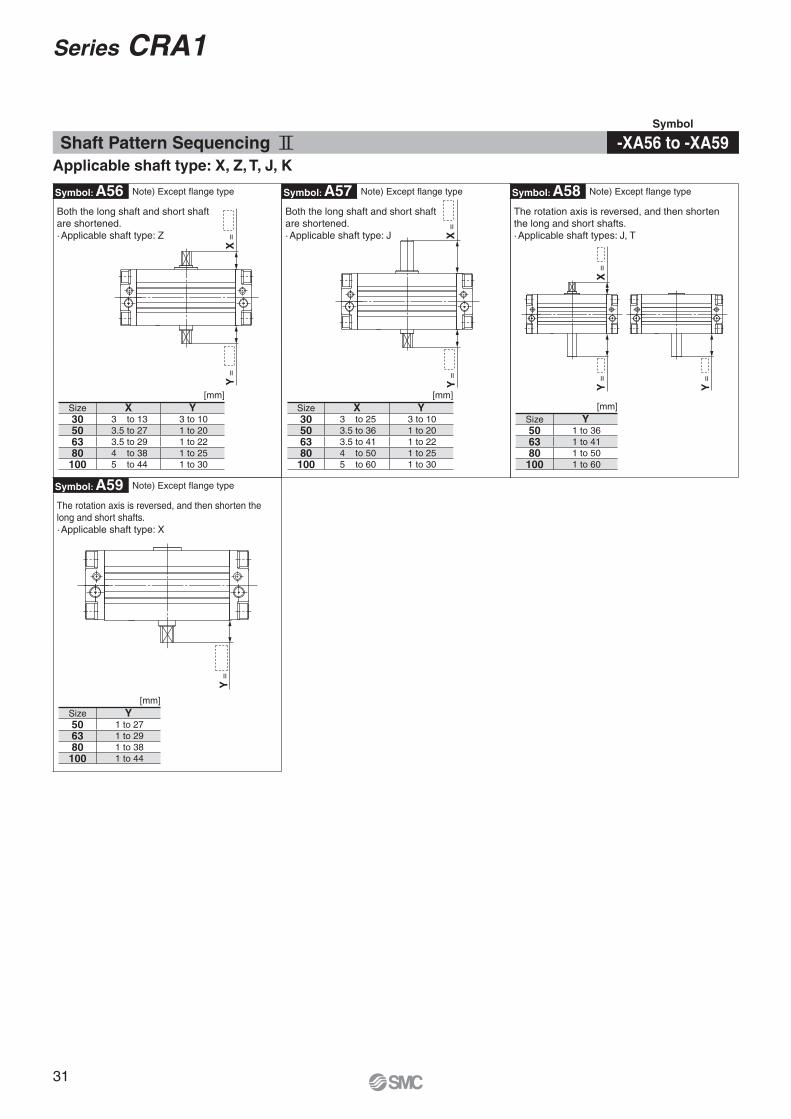
Symbol
Shaft Pattern Sequencing2 -XA33 to -XA59Applicable shaft type: X, Z, T, J, K
How to Order
C RA1 Z XD B J 50 90 M9BW A33 A34 C8 C30
Port typeSize 30 50 63 80 100
—M thread M5 — — — —
Rc —
1/8 1/8 1/4 3/8TF G —
TN NPT —
TT NPTF —
Magnet— None
D Built-in magnet
Size30506380
100
Rotating angle90 90°
180 180°100 Note) 100°190 Note) 190°
Note) Except size 30
Number of auto switches— 2 pcs.
S 1 pc.
Auto switch
— Without auto switch(Built-in magnet)
Note 1) For applicable auto switch model, refer to page 5.
Note 2) Auto switches are shipped together, (but not assembled).
Chart 5. Combination between -XA� and -XC�Symbol Description
Applicable shaft type Applicable size
Combination
X Z T J K -XA33 to 38, 40 to 46, 51 to 59-XC7 Reversed shaft � — � � — 50, 63,
80, 100—
-XC8 to -XC11 Change of rotation range — — — — — —
-XC30 Changed to fl uorine grease � � � � � 30 to 100 �
-XC31 to -XC36 Change of rotation range and shaft rotation direction — — — — —
50, 63, 80, 100
—
-XC37 to -XC46 Change of rotation range and angle adjusting direction — — — — — —
-XC47 to -XC58 Change of rotation range and angle adjusting direction(Angle adjusting screw is equipped on the left.)
— — — — — —
-XC59 to -XC61 Change of port location � � � � � 30 to 100 �
-XC63 One side air-hydro, One side air � � � � � 50, 63, 80, 100
�
-XC64 One side air-hydro, One side air � � � � � �
∗ -XC8 to -XC11 and -XC31 to -XC36 do not include the angle adjustable type.∗ -XC37 to -XC46 and -XC47 to -XC58 are only the angle adjustable type.∗ -XC63 and -XC64 are only the air-hydro type.
Chart 6. Combination between -X� and -XA�Symbol Description
Applicable shaft type Applicable size
Combination
X Z T J K -XA33 to 38, 40 to 46, 51 to 59-X6 Stainless steel shaft/bolt, etc. � � � � �
30 to 100�
-X7 Heat resistant (100 °C) � � � � � �
-X10 Both sides angle adjustable � � � � �50 to 100
�
-X11 One side angle adjustable, One side with cushion � � � � � �
-X16 Fluororubber seal � � � � � 30 to 100 �
∗ -X10 and -X11 are only the angle adjustable type.
28
Simple Specials Series CRA1
CR
A1
Auto
Swi
tch
Moun
ting
Sim
ple
Spe
cial
sM
ade
to O
rder
CR
A1�
�U
Additional Reminders1. Enter the dimensions within a range that allows
for additional machining.2. SMC will make appropriate arrangements if no
dimensional, tolerance, or fi nish instructions are given in the diagram.
3. The length of the unthreaded portion is 2 to 3 pitches.
4. Unless specified otherwise, the thread pitch is based on coarse metric threads.
P = Thread pitchM4 x 0.7, M5 x 0.8M6 x 1, M8 x 1.25, M10 x 1.5
5. Enter the desired fi gures in the portion of the diagram.
6. Chamfer face of the parts machining additionally is C0.5.
Symbol: A35The maximum dimension L1 is, as a rule, twice the thread size.(Example) For M4: L1 = 8·Applicable shaft types: X, Z
Machine female threads into the long shaft. Note) Except fl ange type
Symbol: A38 Note) Except fl ange type
The short shaft can be further shortened by machining it into a stepped round shaft.· The minimum unit of the dimensions within a range that allows for machining is 0.1.
(If shortening the shaft is not required, indicate “∗” for dimension Y.)(If not specifying dimension C2, indicate “∗” instead.)·Applicable shaft type: K·Equal dimensions are indicated by the same marker.
[mm]Size Y L2max D230 3 to 25 Y-2 Ø 5 to Ø 7.950 1 to 36 Y Ø 5 to Ø 14.963 1 to 41 Y Ø 5 to Ø 16.980 1 to 50 Y Ø 8 to Ø 19.9100 1 to 60 Y Ø 8 to Ø 24.9
Symbol: A36The maximum dimension L2 is, as a rule, twice the thread size.(Example) For M4: L2 = 8·Applicable shaft types: X, Z
Machine female threads into the short shaft. Note) Except fl ange type
Symbol: A40 Shaft through-hole Note) Except fl ange type
·Minimum machining diameter for d1 is 0.1.·Applicable shaft types: K, T
[mm]Size d130 Ø 2.550 Ø 4 to Ø 7.563 Ø 4 to Ø 880 Ø 6.8 to Ø 11100 Ø 6.8 to Ø 13
Symbol: A37 Note) Except fl ange type
The long shaft can be further shortened by machining it into a stepped round shaft.· The minimum unit of the dimensions within a range that allows for machining is 0.1.
(If shortening the shaft is not required, indicate “∗” for dimension X.)(If not specifying dimension C1, indicate “∗” instead.)
·Applicable shaft types: J, K, T·Equal dimensions are indicated by the same marker.
[mm]Size X L1max D130 3 to 25 X-2 Ø 5 to Ø 7.950 3.5 to 36 X-2.5 Ø 5 to Ø 14.963 3.5 to 41 X-2.5 Ø 5 to Ø 16.980 4 to 50 X-3 Ø 8 to Ø 19.9100 5 to 60 X-4 Ø 8 to Ø 24.9
Symbol: A41 Shaft through-hole Note) Except fl ange type
·Minimum machining diameter for d1 is 0.1.·Applicable shaft types: J, X, Z
[mm]Size d130 Ø 2.550 Ø 4 to Ø 7.563 Ø 4 to Ø 880 Ø 6.8 to Ø 11100 Ø 6.8 to Ø 13
Symbol: A34The maximum dimension L2 is, as a rule, twice the thread size.(Example) For M4: L2 = 8·Applicable shaft types: J, K, T
Machine female threads into the long shaft. Note) Except fl ange type
Symbol
Shaft Pattern Sequencing2 -XA33 to -XA41Applicable shaft type: X, Z, T, J, K
Q1 = M
L1 +
(3
x P
)
L1 =
Q2 = M
L2 =
Q2 = M
L2 =
Z axis X axis
d1 = ø d1 = ø
K axis T axis
D1 = ø
C1 = C
C1
L1
= X =
d1 = ø d1 = ø
J axis X axis
Q2 = MQ2 = M
L2 +
(3
x P
)
L2 =
L2 +
(3
x P
)
L2 =
Q1 = M
L1 +
(3
x P
)
L1 =
D2 = ø
L2
=
C2
C2 =
C
Y =
29
Series CRA1
Symbol: A46 Note) Except fl ange type
The short shaft can be further shortened by machining a middle-cut chamfer into it.· The minimum unit of the dimensions within a range that allows for machining is 0.1.
(The position is that of the standard fl at at the keyway portion.)(If shortening the shaft is not required, indicate “∗” for dimension Y.)·Applicable shaft type: K
[mm]Size Y W2 L2max L4max30 8.5 to 25 1 to 2 Y-2 L2-250 10 to 36 1 to 5.5 Y L2-263 11 to 41 1 to 6.5 Y L2-2 80 13.5 to 50 1 to 8 Y L2-3100 17 to 60 1.5 to 10.5 Y L2-4
Symbol: A53 Note) Except fl ange type
Both the long shaft and short shaft are shortened.·Applicable shaft type: K
[mm]Size X Y30 3 to 25 3 to 2550 3.5 to 36 1 to 3663 3.5 to 41 1 to 4180 4 to 50 1 to 50100 5 to 60 1 to 60
Symbol: A51 Note) Except fl ange type
Shorten the long shaft.·Applicable shaft types: J, K, T
[mm]Size X30 3 to 2550 3.5 to 3663 3.5 to 4180 4 to 50100 5 to 60
Symbol: A54 Note) Except fl ange type
Shorten the long shaft.·Applicable shaft types: X, Z
[mm]Size X30 3 to 1350 3.5 to 2763 3.5 to 2980 4 to 38100 5 to 44
Symbol: A52 Note) Except fl ange type
Shorten the short shaft.·Applicable shaft type: K
[mm]Size Y30 3 to 2550 1 to 3663 1 to 4180 1 to 50100 1 to 60
Symbol: A55 Note) Except fl ange type
Shorten the short shaft.·Applicable shaft types: J, Z
[mm]Size Y30 3 to 1050 1 to 2063 1 to 2280 1 to 25100 1 to 30
Symbol: A45 Note) Except fl ange type
The long shaft can be further shortened by machining a middle-cut chamfer into it.· The minimum unit of the dimensions within a range that allows for machining is 0.1.
(The position is that of the standard fl at at the keyway portion.)(If shortening the shaft is not required, indicate “∗” for dimension X.)·Applicable shaft types: J, K, T
[mm]Size X W1 L1max L3max30 8.5 to 25 1 to 2 X-2 L1-250 12.5 to 36 1 to 5.5 X-2.5 L1-263 13.5 to 41 1 to 6.5 X-2.5 L1-280 16.5 to 50 1 to 8 X-3 L1-3100 21 to 60 1.5 to 10.5 X-4 L1-4
Symbol: A44 Note) Except fl ange type
Shaft through-hole and female thread machining·Applicable shaft types: J, X, Z· Equal dimensions are indicated by the same marker.
-XC7 -XC8 to -XC11 Change of rotation range � � — � — — — — — -XC8 to -XC11
-XC30 Changed to fl uorine grease � � � � � � � � 30 to 100 S,W,X,T,J∗ S,W,Y∗ -XC30-XC31 to -XC36 Change of rotation range and shaft rotation direction � � — � — — — —
50, 63, 80, 100
— — S,W,Y∗ -XC31 to -XC36-XC37 to -XC46 Change of rotation range and angle adjusting direction � � — � — — — — — — S,W,Y∗ — -XC37 to -XC46
-XC47 to -XC58 Change of rotation range and angle adjusting direction (Angle adjusting screw is equipped on the left.) � � — � — — — — — — — — — -XC47 to -XC58
-XC59 to -XC61 Change of port location � � � � � � � � 30 to 100 S,W,Y∗ � S,W,Y∗ S,W,Y∗ S,W,Y∗ S,W,Y∗ -XC59 to -XC61-XC63 One side air-hydro, One side air � � � � � � � � 50, 63,
80, 100� � — � — — �
-XC64 One side air-hydro, One side air � � � � � � � � � � — � — — �
∗ -XC8 to -XC11 and -XC31 to -XC36 are only the standard type. ∗ -XC37 to -XC46 and -XC47 to -XC58 are only the angle adjustable type.∗ -XC63 and -XC64 are only the air-hydro type.
Chart 8. Combination between -X�, -XC�Symbol Description
Applicable shaft type Applicable size
CombinationS W X Y Z T J K -XC7 -XC8 to -XC11 -XC30 -XC31 to -XC36 -XC37 to -XC58 -XC59 to -XC61 -XC63 -XC64
-X6 Stainless steel shaft/bolt, etc. � � � � � � � �30 to 100
Symbol: C59Direction of the port is changed. (Upward)
Symbol: C60Direction of the port is changed. (Downward)
Symbol: C61Direction of the port is changed. (Backward)
Symbol
One Side Air-hydro, One Side Air -XC63, -XC6410
Standard model no. -XC63
One side air-hydro, One side air-XC63: Left side air Right side air-hydro-XC64: Left side air-hydro Right side air
Specifi cationsApplicable size 50, 63, 80, 100
Applicable shaft typeS, W, X, YZ, T, J, K
∗ Except angle adjustable type and air cushion equipped type
C�RA1
Symbol: C63One side air, one side air-hydro specifi cation (Left side air, Right side hydro)
The fi gure shows the pressurised situation to the hydro pressure port.
Symbol: C64One side air, one side air-hydro specifi cation (Left side hydro, Right side air)
The fi gure shows the pressurised situation to the air pressure port.
Port
Port Port
Port
Port Port
PortPort
Port
Air pressure port Hydro pressure port
Bleeder valve
Hydro pressure port Air pressure port
Bleeder valve
39
Series CRA1
Symbol
Stainless Steel Shaft/Bolt/Parallel Key -X611
Standard model no. -X6
Stainless steel for main part
C�RA1
For applications in areas that pose a risk of rust or corrosion, a portion of the materials used in the standard parts has been changed to stainless steel.
Specifi cationsType Pneumatic, Air-hydro
Size 30, 50, 63, 80, 100
Rotating angle 90°, 180° (Size 30 to 100) 100°, 190° (Size 50 to 100)
Mounting Flange, Foot
Shaft typeSingle shaft (S), Double shaft (W), Single shaft with four chamfers (X), Double shaft with key (Y), Double shaft with four chamfers (Z), Single round shaft (T),
Double shaft (round shaft, with four chamfers) (J), Double round shaft (K)
Stainless steel part Shaft, Bolt, Screw, Parallel key
CushionNot attached, Air cushion (Except air-hydro type)
Auto switch Mountable∗ Refer to page 5 for other specifi cations.∗∗ Except angle adjustable type∗∗∗ Only single shaft (S) and double shaft (W) types are applicable to fl ange type.
Shaft typeSingle shaft (S), Double shaft (W), Single shaft with four chamfers (X), Double shaft with key (Y), Double shaft with four chamfers (Z), Single round shaft (T),
Double shaft (round shaft, with four chamfers) (J), Double round shaft (K)
Cushion None
Angle adjustment range Max. 90° (One side)∗ Refer to page 15 for other specifi cations.
Symbol
Heat Resistant -X712
Standard model no. -X7
Heat resistant
CRA1
Specifi cationsType Pneumatic
Size 30, 50, 63, 80, 100
Rotating angle 90°, 180° (Size 30 to 100) 100°, 190° (Size 50 to 100)
Ambient and fl uid temperature
0 to 100 °C
Mounting Flange, Foot
Shaft typeSingle shaft (S), Double shaft (W), Single shaft with four chamfers (X), Double shaft with key (Y), Double shaft with four chamfers (Z), Single round shaft (T),
Double shaft (round shaft, with four chamfers) (J), Double round shaft (K)
Seal material FKM
CushionSize 30: None
Size 50 to 100: Not attached, Air cushion
Auto switch Not mountable∗ Refer to page 5 for other specifi cations.
In this rotary actuator, the material of the seals has been changed to the heat resistant type (to withstand up to 100 °C), for applications in environments that exceed the standard specifi cation temperatures of 0 to 60 °C.
Adjusting direction Adjusting direction “A”: When angle adjusting screw on “A” side is screwed into the right direction.Adjusting direction “B”: When angle adjusting screw on “B” side is screwed into the right direction.
Angle adjusting screw "B"
Angle adjusting screw "A"
Rotation at 90
Rotation range
of k
eyw
ay 9
0
angle adjusting screw “A”
ang
le ad
justin
g sc
rew
“B”
Adjusting direction with
Adjus
ting
direc
tion
with
Angle adjusting screw "B"
Angle adjusting screw "A"
Rotation at 180
Rotation range of keyway 180
Adjusting direction with
Adjust
ing
dire
ctio
n w
ith
angle adjusting screw “A”
angl
e ad
just
ing
scre
w “
B”
40
Made to Order Series CRA1
Auto
Swi
tch
Moun
ting
Sim
ple
Spe
cial
sM
ade
to O
rder
CR
A1�
�U
CR
A1
Symbol
One Side Angle Adjustable, One Side with Cushion -X1114
Shaft typeSingle shaft (S), Double shaft (W), Single shaft with four chamfers (X), Double shaft with key (Y), Double shaft with four chamfers (Z), Single round shaft (T),
Double shaft (round shaft, with four chamfers) (J), Double round shaft (K)
Cushion With cushion on one side
Angle adjustment range Max. 90°∗ Refer to page 15 for other specifi cations.
Symbol
Fluororubber Seal -X1615
Standard model no. -X16
Fluororubber seal
CDRA1
Seal is now changed to fl uororubber.
Specifi cationsType Pneumatic
Size 30, 50, 63, 80, 100
Rotating angle 90°, 180° (Size 30 to 100) 100°, 190° (Size 50 to 100)
Ambient and fl uid temperature
0 to 60 °C (No freezing)
Mounting Flange, Foot
Shaft typeSingle shaft (S), Double shaft (W), Single shaft with four chamfers (X), Double shaft with key (Y), Double shaft with four chamfers (Z), Single round shaft (T),
Double shaft (round shaft, with four chamfers) (J), Double round shaft (K)
Seal material FKM
Cushion Not attached, Air cushion
Auto switch Mountable∗ Refer to page 5 for other specifi cations.∗∗ For built-in magnet type only.
∗ Refer to page 17 for dimensions.
Rotation at 90
Cushion valve
Angle adjusting screw
of cu
shion
Opera
ting r
ange
Rotation range of k
eyway
90
Angle adjusting direction
Rotation at 180
Cushion valve
Angle adjusting screw
Rotation range of keyway 180
Angle adjusting direction
of cu
shion
Opera
ting r
ange
41
Series CRA1
How to Order
Series CRA1Made to Order: -X6 to -X16
C RA1 ZD B S 50 90 X6 X16M9BW
Port typeSize 30 50 63 80 100
—M thread M5 — — — —
Rc —
1/8 1/8 1/4 3/8TF G —
TN NPT —
TT NPTF —
Magnet— None
D Built-in magnet
Size30506380
100
Rotating angle90 90°
180 180°100 Note) 100°190 Note) 190°
Note) Except size 30
Number of auto switches— 2 pcs.
S 1 pc.
Auto switch
— Without auto switch (Built-in magnet)
Note 1) For applicable auto switch model, refer to page 5.
Note 2) Auto switches are shipped together, (but not assembled).
MountingB Basic type
L Foot type
F Flange type
Shaft typeS Single shaft
W Double shaft
X Single shaft with four chamfers
Y Double shaft with key
Z Double shaft with four chamfers
T Single round shaft
J Double shaft (round shaft, with four chamfers)
K Double round shaft
Note 1) Combination of made-to-order -X is possible for up to 2 types.Note 2) Above is the typical example of combination.
-X11 One side angle adjustable, One side with cushion � � � � � � � � — � -X10 to -X11-X16 Fluororubber seal � � � � � � � � 30 to 100 � — �
∗ X7: Not available for the built-in magnet type.
42
Auto
Swi
tch
Moun
ting
Sim
ple
Spe
cial
sM
ade
to O
rder
CR
A1�
�U
CR
A1
Caution on Design
Warning1. Do not use a rotary actuator of the air-hydro type
near fl ames, or in equipment or machinery that ex-ceeds an ambient temperatures of 60 °C.There is a danger of causing a fi re because the rotary actuator of the air-hydro type uses a fl ammable hydraulic fl uid.
Caution1. Do not use in an environment, equipment, or ma-
chine that is not compatible with oil mist.Rotary actuators of the air-hydro types generate an oil mist during operation which may affect the environment.
2. Be sure to install an exhaust cleaner on the direc-tional control valve for the rotary actuator of the air-hydro type.A very small amount of hydraulic fl uid is discharged from the exhaust port of the rotary actuator of the air-hydro type’s direc-tional control valve, which may contaminate the surrounding area.
3. Install a rotary actuator of the air-hydro type in loca-tions where it can be serviced easily.Since the rotary actuator of the air-hydro type requires mainte-nance, such as refi lling of hydraulic fl uid and bleeding of air, ensure suffi cient space for these activities.
4. Do not use in cases where external leakage of hy-draulic oil may adversely affect equipment or ma-chinery.Although it only occurs in minute amounts, a certain amount of sliding leakage from the piston seal is unavoidable with the ro-tary actuator of the air-hydro type. Because of the construction of the rotary actuator of the air-hydro type, hydraulic oil may leak into the outside due to sliding leakage.
Selection
Caution1. Select the rotary actuator of the air-hydro type based
on the combination with the air-hydro unit.Select a proper air-hydro unit that is necessary for good opera-tion of the rotary actuator of the air-hydro type.
Piping
Caution1. Use self-align fi ttings in conjunction with the piping
for the rotary actuator of the air-hydro type.Do not use a one-touch fi tting with the piping for the rotary ac-tuator of the air-hydro type, as this may result in oil leakage.
Piping
Caution2. For rotary actuator of the air-hydro type piping, use
hard nylon tubing or copper piping.As in the case of hydraulic circuits, surge pressures greater than the operating pressure may occur in a rotary actuator of the air-hydro type’s piping, making it necessary to use safer piping materials.
Lubrication
Warning1. Make sure to completely discharge the compressed
air in the system before fi lling the air-hydro unit with hydraulic oil.When supplying hydraulic fl uid to the air-hydro unit, fi rst con-fi rm that safety measures are implemented to prevent dropping of objects and the release of clamped objects, etc. Then, shut off the air supply and the equipment’s electric power and ex-haust the compressed air in the system.If the air-hydro unit’s supply port is opened with compressed air still remaining in the system, there is a danger of hydraulic fl uid being blown out.
Maintenance
Caution1. Bleed air from the rotary actuator of the air-hydro
type on a regular basis.Since air may accumulate inside a rotary actuator of the air-hy-dro type, bleed air from it, for example before starting work. Bleed air from a bleeder valve provided on the rotary actuator of the air-hydro type or the piping.
A port B port
Bleeder valve(B port side)
Bleeder valve(A port side)
2. Verify the oil level of the air-hydro system on a regu-lar basis.Since a very small amount of hydraulic fl uid is discharged from the rotary actuator of the air-hydro type and air-hydro unit cir-cuit, the fl uid will gradually decrease. Therefore, check the fl uid regularly and refi ll as necessary.The oil level can be checked with a level gauge in the air-hydro converter.
How to Use the Air-hydro Type
Series CRA1Specifi c Product PrecautionsBe sure to read this before handling. Refer to the back cover for Safety Instructions. For Rotary Actuator Precautions and Auto Switch Precautions, refer to “Handling Precautions for SMC Products” and the Operation Manual on SMC website, http://www.smcworld.com
Specifications are subject to change without prior notice and any obligation on the part of the manufacturer.SMC CORPORATION Akihabara UDX 15F, 4-14-1, Sotokanda, Chiyoda-ku, Tokyo 101-0021, JAPAN Phone: 03-5207-8249 FAX: 03-5298-5362
Safety Instructions Be sure to read “Handling Precautions for SMC Products” (M-E03-3) before using.
SMC Corporation (Europe)
1. The compatibility of the product is the responsibility of the person who designs the equipment or decides its specifications.
Since the product specified here is used under various operating conditions, its compatibility with specific equipment must be decided by the person who designs the equipment or decides its specifications based on necessary analysis and test results. The expected performance and safety assurance of the equipment will be the responsibility of the person who has determined its compatibility with the product. This person should also continuously review all specifications of the product referring to its latest catalogue information, with a view to giving due consideration to any possibility of equipment failure when configuring the equipment.
2. Only personnel with appropriate training should operate machinery and equipment.
The product specified here may become unsafe if handled incorrectly. The assembly, operation and maintenance of machines or equipment including our products must be performed by an operator who is appropriately trained and experienced.
3. . Do not service or attempt to remove product and machinery/equipment until safety is confirmed.1. The inspection and maintenance of machinery/equipment should only be performed
after measures to prevent falling or runaway of the driven objects have been confirmed.
2. When the product is to be removed, confirm that the safety measures as mentioned above are implemented and the power from any appropriate source is cut, and read and understand the specific product precautions of all relevant products carefully.
3. Before machinery/equipment is restarted, take measures to prevent unexpected operation and malfunction.
4. Contact SMC beforehand and take special consideration of safety measures if the product is to be used in any of the following conditions. 1. Conditions and environments outside of the given specifications, or use outdoors or in
a place exposed to direct sunlight.2. Installation on equipment in conjunction with atomic energy, railways, air navigation,
space, shipping, vehicles, military, medical treatment, combustion and recreation, or equipment in contact with food and beverages, emergency stop circuits, clutch and brake circuits in press applications, safety equipment or other applications unsuitable for the standard specifications described in the product catalogue.
3. An application which could have negative effects on people, property, or animals requiring special safety analysis.
4. Use in an interlock circuit, which requires the provision of double interlock for possible failure by using a mechanical protective function, and periodical checks to confirm proper operation.
Warning Limited warranty and Disclaimer/Compliance Requirements The product used is subject to the following “Limited warranty and Disclaimer” and “Compliance Requirements”.Read and accept them before using the product.
1. The product is provided for use in manufacturing industries.The product herein described is basically provided for peaceful use in manufacturing industries. If considering using the product in other industries, consult SMC beforehand and exchange specifications or a contract if necessary. If anything is unclear, contact your nearest sales branch.
CautionSMC products are not intended for use as instruments for legal metrology.Measurement instruments that SMC manufactures or sells have not been qualified by type approval tests relevant to the metrology (measurement) laws of each country.Therefore, SMC products cannot be used for business or certification ordained by the metrology (measurement) laws of each country.
Caution
Limited warranty and Disclaimer1. The warranty period of the product is 1 year in service or 1.5 years
after the product is delivered, wichever is first.∗2)
Also, the product may have specified durability, running distance or replacement parts. Please consult your nearest sales branch.
2. For any failure or damage reported within the warranty period which is clearly our responsibility, a replacement product or necessary parts will be provided. This limited warranty applies only to our product independently, and not to any other damage incurred due to the failure of the product.
3. Prior to using SMC products, please read and understand the warranty terms and disclaimers noted in the specified catalogue for the particular products.
∗2) Vacuum pads are excluded from this 1 year warranty.A vacuum pad is a consumable part, so it is warranted for a year after it is delivered. Also, even within the warranty period, the wear of a product due to the use of the vacuum pad or failure due to the deterioration of rubber material are not covered by the limited warranty.
Compliance Requirements1. The use of SMC products with production equipment for the manufacture of
weapons of mass destruction (WMD) or any other weapon is strictly prohibited.
2. The exports of SMC products or technology from one country to another are governed by the relevant security laws and regulations of the countries involved in the transaction. Prior to the shipment of a SMC product to another country, assure that all local rules governing that export are known and followed.
These safety instructions are intended to prevent hazardous situations and/or equipment damage. These instructions indicate the level of potential hazard with the labels of “Caution,” “Warning” or “Danger.” They are all important notes for safety and must be followed in addition to International Standards (ISO/IEC)∗1), and other safety regulations.
∗1) ISO 4414: Pneumatic fluid power – General rules relating to systems. ISO 4413: Hydraulic fluid power – General rules relating to systems. IEC 60204-1: Safety of machinery – Electrical equipment of machines. (Part 1: General requirements) ISO 10218-1: Manipulating industrial robots - Safety. etc.
Caution indicates a hazard with a low level of risk which, if not avoided, could result in minor or moderate injury.
Warning indicates a hazard with a medium level of risk which, if not avoided, could result in death or serious injury.
Caution:
Warning:
Danger : Danger indicates a hazard with a high level of risk which, if not avoided, will result in death or serious injury.