Door-coupling version withred/yellow padlock handle system.Types: GX…O88 – GX…098.Page 8.
Front mounting version.Type: GX…U.Pages 4 to 6.
Door coupling version.Types: GX…O68 – GX…O78.Page 8.
Available infour different ratings,
16, 20, 32 and 40A,and an assortment
of versions.
start
disconnect
switch
reverse
Rotarycam switchesGX series
Compact and finger safe (IP20protection of contacts).
Designed according to the latesttechnology in the switchingdevice field and made of the bestquality materials, these camswitches are characterised byhigh breaking capacity, long life(both mechanical and electrical),installation ease as well ascompact size.The contacts are dual breakingand made of silver alloy. Theterminals have cross-slottedcaptive screws and are selfreleasing.
GX rotary cam switches can beused for isolation, motor controlin AC3 and AC23 duties andelectromagnetic load switching,AC15 duty.
100% electricity
Modular DIN rail mount version.Type: GX…O48.Page 9.
Front mounting version withred/yellow padlock system.Types: GX…U25 – GX…U65.Page 7.
Enclosure version withpadlockable rotating handle.Type: GX…P25.Page 10.
Front-mounting version withhandle operation for 22mmcentral fixing. Type: GX…U11.Page 7.
Example of switchmounting for version U
Example of switchmounting for version O
• • • •OU
ORDER CODE STRUCTURE:
U = front mounting
O = doorcoupling
16 A20 A32 A40 A
See page 12 See pages 4 to 8
RATING SCHEME OPTIONALSVERSION
Key operation version for22mm central fixing.
Type: GX…U12.Page 7.
Enclosure versionType: GX…P.Page 10.
G X • •
General characteristics- 16 to 40A rated thermal current Ith ratings- Extended mechanical and electrical life- Switching angles: 30°, 45°, 60° and 90°- Silver-alloy dual-breaking contacts- IP40 front degree of protection (for IP65, see
“Optional” below); IP20 protection of contacts- Operating temperature: -25° to +55°C- Legend marking is standard supplied as illustrated in
the order code table; any other on request.
Certifications and complianceCertifications obtained: cULus.Compliant to standards: IEC/EN 60947-3,IEC/EN 60204-1, IEC/EN 61058-1.
Selection guideSee page 14.
OptionalIP65 protection front plate:Add “51” at the end of the order codeE.g. GX16 92 U 51.
Enlarged front plate for GX16-GX20 (65x65mm insteadof standard 48x48):Add “H” after the switch rating in the order codeE.g. GX16H 10 U.
Enlarged front plate for GX32-GX40 (90x90mm insteadof standard 65x65):Add “H” after the switch rating in the order codeE.g. GX32H 10 U.
Example of U version switch mounting
Order Rated Front Q.ty Weightcode current plate per
AC1 size pkg[A] [mm] n° [kg]
ON/OFF SWITCHES.One-pole – 1 wafer – scheme 90.GX16 90 U 16 ■■ 48 1 0.093GX20 90 U 20 ■■ 48 1 0.096GX32 90 U 32 ■■ 65 1 0.222GX40 90 U 40 ■■ 65 1 0.223Two-pole – 1 wafer – scheme 91.GX16 91 U 16 ■■ 48 1 0.097GX20 91 U 20 ■■ 48 1 0.101GX32 91 U 32 ■■ 65 1 0.244GX40 91 U 40 ■■ 65 1 0.256Three-pole – 2 wafers – scheme 10.GX16 10 U 16 ■■ 48 1 0.113GX20 10 U 20 ■■ 48 1 0.120GX32 10 U 32 ■■ 65 1 0.296GX40 10 U 40 ■■ 65 1 0.312Four-pole – 2 wafers – scheme 92.GX16 92 U 16 ■■ 48 1 0.110GX20 92 U 20 ■■ 48 1 0.124GX32 92 U 32 ■■ 65 1 0.301GX40 92 U 40 ■■ 65 1 0.326
Rotary cam switchesGX Series
4
01
01
01
01
U version front mounting.ON/OFF switches
electric
Technical characteristicspage 14
Dimensionspage 12
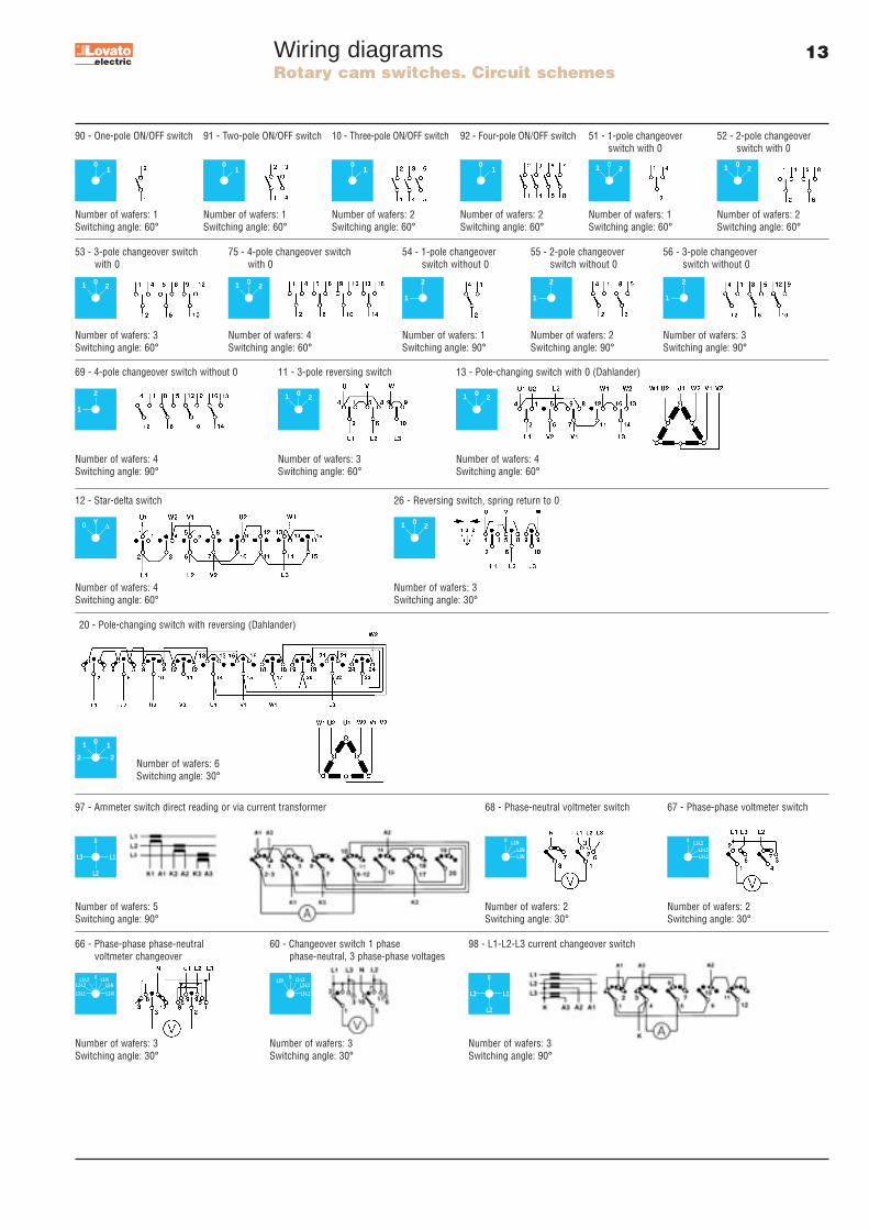
Wiring diagramspage 13
Accessories page 11
Rotary cam switchesGX Series
5
0 21
2
1
2
1
2
1
2
1
Order Rated Front Q.ty Weightcode current plate per
AC1 size pkg[A] [mm] n° [kg]
CHANGEOVER SWITCHES WITH 0.One-pole – 1 wafer – scheme 51.GX16 51 U 16 ■■ 48 1 0.097GX20 51 U 20 ■■ 48 1 0.101GX32 51 U 32 ■■ 65 1 0.236GX40 51 U 40 ■■ 65 1 0.239Two-pole – 2 wafers – scheme 52.GX16 52 U 16 ■■ 48 1 0.120GX20 52 U 20 ■■ 48 1 0.124GX32 52 U 32 ■■ 65 1 0.309GX40 52 U 40 ■■ 65 1 0.326Three-pole – 3 wafers – scheme 53.GX16 53 U 16 ■■ 48 1 0.138GX20 53 U 20 ■■ 48 1 0.146GX32 53 U 32 ■■ 65 1 0.371GX40 53 U 40 ■■ 65 1 0.402Four-pole – 4 wafers – scheme 75.GX16 75 U 16 ■■ 48 1 0.157GX20 75 U 20 ■■ 48 1 0.171GX32 75 U 32 ■■ 65 1 0.440GX40 75 U 40 ■■ 65 1 0.472CHANGEOVER SWITCHES WITHOUT 0.One-pole – 1 wafer – scheme 54.GX16 54 U 16 ■■ 48 1 0.098GX20 54 U 20 ■■ 48 1 0.102GX32 54 U 32 ■■ 65 1 0.121Two-pole – 2 wafers – scheme 55.GX16 55 U 16 ■■ 48 1 0.117GX20 55 U 20 ■■ 48 1 0.126GX32 55 U 32 ■■ 65 1 0.155Three-pole – 3 wafers – scheme 56.GX16 56 U 16 ■■ 48 1 0.137GX20 56 U 20 ■■ 48 1 0.146GX32 56 U 32 ■■ 65 1 0.186Four-pole – 4 wafers – scheme 69.GX16 69 U 16 ■■ 48 1 0.158GX20 69 U 20 ■■ 48 1 0.171GX32 69 U 32 ■■ 65 1 0.224
0 21
0 21
0 21
General characteristics- 16 to 40A rated thermal current Ith ratings- Extended mechanical and electrical life- Switching angles: 30°, 45°, 60° and 90°- Silver-alloy dual-breaking contacts- IP40 front degree of protection (for IP65, see
“Optional” below); IP20 protection of contacts- Operating temperature: -25° to +55°C- Legend marking is standard supplied as illustrated in
the order code table; any other on request.
Certifications and complianceCertifications obtained: cULus.Compliant to standards: IEC/EN 60947-3,IEC/EN 60204-1, IEC/EN 61058-1.
Selection guideSee page 14.
OptionalIP65 protection front plate:Add “51” at the end of the order codeE.g. GX16 75 U 51.
Enlarged front plate for GX16-GX20 (65x65mm insteadof standard 48x48):Add “H” after the switch rating in the order codeE.g. GX16H 52 U.
Enlarged front plate for GX32-GX40 (90x90mm insteadof standard 65x65):Add “H” after the switch rating in the order codeE.g. GX32H 52 U.
Example of U version switch mounting
U version front mounting.Changeover switcheswith 0 position. Changeover switcheswithout 0 position
electric
Technical characteristicspage 14
Dimensionspage 12
Wiring diagramspage 13
Accessories page 11
Order Ith Max Front Q.ty Wt.code AC1 power plate per
AC23A size pkg[A] [kW] [mm] n° [kg]
MOTOR SWITCHES.Reversing switches. Three-pole – 3 wafers – scheme 11.GX16 11 U 16 6.5 ■■ 48 1 0.133GX20 11 U 20 7.5 ■■ 48 1 0.141GX32 11 U 32 15 ■■ 65 1 0.362GX40 11 U 40 18.5 ■■ 65 1 0.383Pole-changing switches. 4 wafers – scheme 13.GX16 13 U 16 6.5 ■■ 48 1 0.161GX20 13 U 20 7.5 ■■ 48 1 0.171GX32 13 U 32 15 ■■ 65 1 0.447GX40 13 U 40 18.5 ■■ 65 1 0.478Star-delta switches. 2 wafers – scheme 12.GX16 12 U 16 6.5 ■■ 48 1 0.158GX20 12 U 20 7.5 ■■ 48 1 0.171GX32 12 U 32 15 ■■ 65 1 0.448GX40 12 U 40 18.5 ■■ 65 1 0.4783-pole motor reversing switches with spring return to 0. 3 wafers – scheme 26.GX16 26 U 16 6.5 ■■ 48 1 0.134GX20 26 U 20 7.5 ■■ 48 1 0.141GX32 26 U 32 15 ■■ 65 1 0.185
0 21
0 21
0 21
Y∆0
General characteristics- 16 to 40A rated thermal current Ith ratings- Extended mechanical and electrical life- Switching angles: 30°, 45°, 60° and 90°- Silver-alloy dual-breaking contacts- IP40 front degree of protection (for IP65, see
“Optional” below); IP20 contact degree of protection- Operating temperature: -25° to +55°C- Legend marking is standard supplied as illustrated in
the order code table; any other on request.Certifications and complianceCertifications obtained: cULus.Compliant to standards: IEC/EN 60947-3,IEC/EN 60204-1, IEC/EN 61058-1.SelectionSee page 14.OptionalIP65 protection front plate: Add “51” at the end of theorder code E.g. GX16 11 U 51.Enlarged front plate for GX16-GX20 (65x65mm insteadof standard 48x48): Add “H” after the switch rating inthe order code E.g. GX16H 11 U.Enlarged front plate for GX32-GX40 (90x90mm insteadof standard 65x65): Add “H” after the switch rating inthe order code E.g. GX32H 11 U.Example of U version switch mounting
Rotary cam switchesGX Series
6
U version front mounting.Motor switches
Order Rated Front Q.ty Weightcode current plate per
For 3 phase to phase voltage and 3 phase voltage readings3 wafers – scheme 66.GX16 66 U 16 ■■ 48 1 0.128
For 1 phase voltage and 3 phase to phase voltage readings3 wafers – scheme 60.GX16 60 U 16 ■■ 48 1 0.133
AMMETER SWITCHES.Direct L1-L2-L3 current readings – 5 wafers – scheme 97.GX16 97 U 16 ■■ 48 1 0.169
For L1-L2-L3 readings via 3 CTs – 3 wafers – scheme 98.GX16 98 U 16 ■■ 48 1 0.146
General characteristics- 16A capacity rating- Extended mechanical and electrical life- Switching angles: 30°, 45°, 60° and 90°- Silver-alloy dual-breaking contacts- IP40 front degree of protection (for IP65, see
“Optional” below); IP20 contact degree of protection- Operating temperature: -25° to +55°C- Circuit schemes on page 12 - Legend marking is standard supplied as illustrated in
the order code table; any other on request.Certifications and complianceCertifications obtained: cULus.Compliant to standards: IEC/EN 60947-3,IEC/EN 60204-1, IEC/EN 61058-1.SelectionSee page 14.OptionalIP65 protection front plate: Add “51” at the end of theorder code E.g. GX16 11 U 51.Enlarged front plate for GX16 (65x65mm instead ofstandard 48x48): Add “H” after the switch rating in theorder code E.g. GX16H 11 U.Example of U version switch mounting
0
L3NL2N
L1N
0
L3-L1L2-L3
L1-L2
0
L3-L1 L3-NL2-NL2-L3
L1-NL1-L2
0
L3-L1L2-L3
L1-L2L1N
0
L2
L3 L1
0
L2
L3 L1
U versionfront mounting.Voltmeterswitches.Ammeter switches
electric
Technical characteristicspage 14
Dimensionspage 12
Wiring diagramspage 13
Accessories page 11
Rotary cam switchesGX Series
7
Order Rated Front Q.ty Weightcode current plate per
U25-U65 versions front mounting withred/yellow padlocksystem.ON/OFF switches
01
01
General characteristics- 16 to 40A rated thermal current Ith ratings- Extended mechanical and electrical life- Switching angles: 30°, 45°, 60° and 90°- Silver-alloy dual-breaking contacts- IP40 front degree of protection (for IP65, see
“Optional” below); IP20 protection of contacts- Operating temperature: -25° to +55°C- Legend marking for U11 and U12 versions is only for
reference while for U25 and U65 types standardsupplied as illustrated in the order code table; anyother on request.
Certifications and complianceCertifications obtained: cULus.Compliant to standards: IEC/EN 60947-3,IEC/EN 60204-1, IEC/EN 61058-1.
SelectionSee page 14.
OptionalIP65 protection front plate:Add “51” at the end of the order codeE.g. GX16 92 U11 51.
Enlarged front plate for GX16-GX20 (65x65mm insteadof standard 48x48):Add “H” after the switch rating in the order codeE.g. GX16H 10 U25.
Enlarged front plate for GX32-GX40 (90x90mm insteadof standard 65x65):Add “H” after the switch rating in the order codeE.g. GX32H 10 U25.
Example of U25-U65 switch mounting
electric
Technical characteristicspage 14
Dimensionspage 12
Wiring diagramspage 13
Accessories page 11
Rotary cam switchesGX Series
8
Order Rated Front Q.ty Weightcode current plate per
General characteristics- 16 to 40A rated thermal current Ith ratings- Extended mechanical and electrical life- Switching angles: 30°, 45°, 60° and 90°- Silver-alloy dual-breaking contacts- IP40 front degree of protection (for IP65, see
“Optional” below); IP20 contact degree of protection- Operating temperature: -25° to +55°C- Suitable for screw fixing or mounting on 35mm DIN
rail (EN 50022)- Legend marking is standard supplied as illustrated in
the order code table; any other on request.
Certifications and complianceCertifications obtained: cULus.Compliant to standards: IEC/EN 60947-3,IEC/EN 60204-1, IEC/EN 61058-1.
SelectionSee page 14.
OptionalIP65 protection front plate:Add “51” at the end of the order codeE.g. GX16 10 088 51.
Enlarged front plate for GX16-GX20 (65x65mm insteadof standard 48x48):Add “H” after the switch rating in the order codeE.g. GX16H 10 O88.
Enlarged front plate for GX32-GX40 (90x90mm insteadof standard 65x65):Add “H” after the switch rating in the order codeE.g. GX32H 10 O88.
Example of O version switch mounting
electric
Technical characteristicspage 14
Dimensionspage 12
Wiring diagramspage 13
Accessories page 11
Rotary cam switchesGX Series
9
Order Rated Front Q.ty Weightcode current plate per
ON/OFF SWITCHES.Three poles - scheme 10.GX16 10 P 16 90x90 1 0.216GX20 10 P 20 90x90 1 0.216GX32 10 P 32 110x110 1 0.440GX40 10 P 40 110x110 1 0.440ON/OFF SWITCHES.Four poles - scheme 92.GX16 92 P 16 90x90 1 0.216GX20 92 P 20 90x90 1 0.216GX32 92 P 32 110x110 1 0.440GX40 92 P 40 110x110 1 0.440CHANGEOVER SWICTHES.Three poles - scheme 53.GX16 53 P 16 90x90 1 0.216GX20 53 P 20 90x90 1 0.216GX32 53 P 32 110x110 1 0.440GX40 53 P 40 110x110 1 0.440CHANGEOVER SWICTHES.Four poles - scheme 75.GX16 75 P 16 90x90 1 0.216GX20 75 P 20 90x90 1 0.216GX32 75 P 32 110x110 1 0.440GX40 75 P 40 110x110 1 0.440
Rotary cam switchesGX Series
10electric
P version inenclosure withrotating handle.On/Off switches.Changeover switches
01
01
0 21
0 21
General characteristics– 16 to 40A rated thermal current ratings– Extended mechanical and electrical life– Switching angles: 30°, 45°, 60° and 90°– Silver-alloy dual-breaking contacts– IP65 degree of protection– Operating temperature: -25° to +55°C– Top and bottom entry: 4 PG16 threaded knockouts for
90x90mm types and 4 PG21 for 110x110mm– Legend marking is standard supplied as illustrated in
the order code table; any other on request.
Certifications and complianceCertifications obtained: cULus.Compliant to standards: IEC/EN 60947-3, IEC/EN 60204-1, IEC/EN 61058-1.
Selection guideSee page 14.
Technical characteristicspage 14
Dimensionspage 12
Wiring diagramspage 13
Accessories page 11
Order Ith Max Housing Qty Wt.code AC1 power size per
AC23A pkg[A] [A] [mm] n° [kg]
MOTOR SWITCHES.Three-pole reversing switches - scheme 11.GX16 11 P 16 6.5 90x90 1 0.271GX20 11 P 20 7.5 90x90 1 0.271GX32 11 P 32 15 110x110 1 0.482GX40 11 P 40 18.5 110x110 1 0.482
SELECTION GUIDEThe choice of a rotary cam switch and the relative type are basedon the functional diagram and the type of application as well.IEC standards provide a comprehensible and quick classificationof the most frequent utilisation categories:AC1: Connection and disconnection of non-inductive or
slightly inductive loads (cosϕ ≥0.95)AC21: Resistance furnacesAC3: Starting and switching off motors during runningAC23A: Switching of motor loads or other highly inductive loadsAC15: Control of electromagnetic loadsFor DC applications, the rotary cam switches are used for theswitching of minor loads or in control circuits, such as:DC13: Control of electromagnetsDC21A: Switching of resistive loadsDC23: Switching of highly inductive loadsOther prescriptions and recommendations concerning the use ofcam switches as auxiliary equipment of electrical machines aregiven in IEC/EN 60204-1 standards and specifically as givenunder utilisation.
UTILISATIONMAIN SUPPLY DISCONNECTING SWITCH WITHEMERGENCY-STOP OPERATION:– Red operating handle with yellow background– Lockable in open position (OFF).
EMERGENCY-STOP SWITCH– Red operating handle with yellow background– Independent operation and the breaking of the load circuit of
switching devices before the opening of its main contacts– Rated capacity is to sufficient in order to break the sum of
the rated operating currents of all the connected equipment – Breaking capacity equal to the current of the largest motor
when stalled (locked rotor) together with the total of thenormal running currents of the other motors or loads.
MAIN SUPPLY DISCONNECTING SWITCH– Used to disconnect all live electrical equipment from the
power supply circuit– Contact clearance distance is to comply with
IEC/EN 60947-3 standards– Provided with a means in order to be locked in the OFF
position – Selection of current breaking according to AC1 and AC21
utilisation categories.
Operationalcharacteristics
GX16... GX20... GX32... GX40...TYPERated insulation voltage ❶Ui IEC/EN
Overlapping Closed contact Open/ Closed Springcontacts in 2 or more passing contact return
positions contact
Type:
Date: Scheme:
PD11
GB
07 0
4
AC motor drives, VFS11 series
Digital multimetersDMK20, DMK25 and DMK50 series
The products described in thisdocumentation are subject to be revisedor improved at any moment.Catalogue descriptions and details, suchas technical and operational data,drawings, diagrams and instructions,etc., do not have any contractual value. Inaddition, products should be installed andused by qualified personnel and incompliance with the regulations in forcefor electrical systems in order to avoiddamages and safety hazards.
2004
Planet-SWITCHPlanet-SWITCHPlanet-SWITCHPlanet-SWITCHPlanet-SWITCHPlanet-SWITCH• Motor protection
circuit breakers• Switch disconnectors• Contactors• Motor protection relays• Electromechanical starters• Push-buttons and selectors• Position and