20
Free air delivery: 0.26 to 86 m³/min, Pressure 5.5 to 15 bar Rotary Screw Compressors SX–HSD Series With the world-renowned SIGMA PROFILE www.kaeser.com

Free air delivery: 0.26 to 86 m³/min, Pressure 5.5 to 15 bar
Rotary Screw CompressorsSX–HSD SeriesWith the world-renowned SIGMA PROFILE
www.kaeser.com
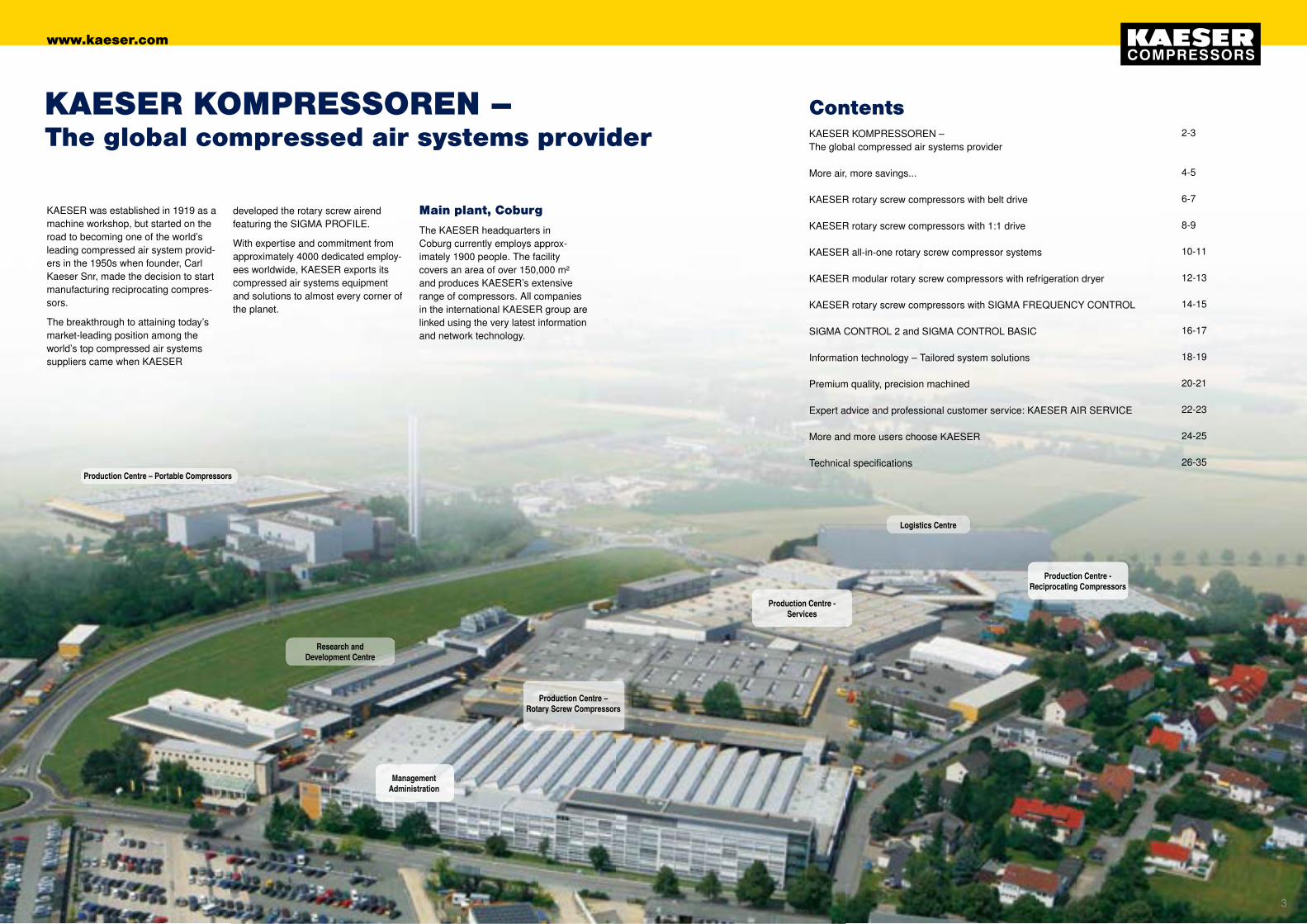
Production Centre – Portable Compressors
Research and Development Centre
Management Administration
Production Centre - Services
Logistics Centre
Production Centre - Reciprocating Compressors
Production Centre – Rotary Screw Compressors
KAESER KOMPRESSOREN – The global compressed air systems provider More air, more savings... KAESER rotary screw compressors with belt drive KAESER rotary screw compressors with 1:1 drive KAESER all-in-one rotary screw compressor systems KAESER modular rotary screw compressors with refrigeration dryer KAESER rotary screw compressors with SIGMA FREQUENCY CONTROL SIGMA CONTROL 2 and SIGMA CONTROL BASIC Information technology – Tailored system solutions Premium quality, precision machined Expert advice and professional customer service: KAESER AIR SERVICE More and more users choose KAESER Technical specifications
2-3 4-5 6-7 8-9 10-11 12-13 14-15 16-17 18-19 20-21 22-23 24-25 26-35
Contents
KAESER was established in 1919 as a machine workshop, but started on the road to becoming one of the world’s leading compressed air system provid-ers in the 1950s when founder, Carl Kaeser Snr, made the decision to start manufacturing reciprocating compres-sors.
The breakthrough to attaining today’s market-leading position among the world’s top compressed air systems suppliers came when KAESER
KAESER KOMPRESSOREN –The global compressed air systems provider
Main plant, Coburg
The KAESER headquarters in Coburg currently employs approx- imately 1900 people. The facility covers an area of over 150,000 m² and produces KAESER’s extensive range of compressors. All companies in the international KAESER group are linked using the very latest information and network technology.
developed the rotary screw airend featuring the SIGMA PROFILE.
With expertise and commitment from approximately 4000 dedicated employ-ees worldwide, KAESER exports its compressed air systems equipment and solutions to almost every corner of the planet.
32
www.kaeser.com
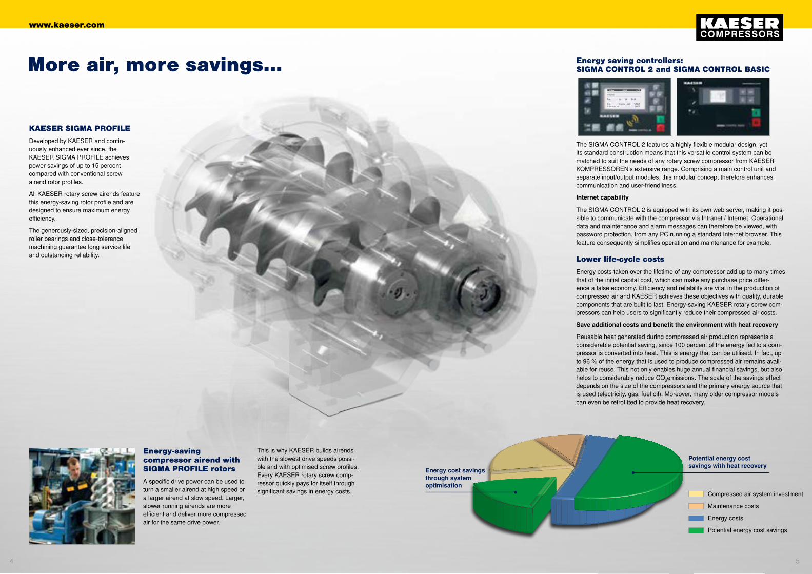
KAESER SIGMA PROFILE
Developed by KAESER and contin- uously enhanced ever since, the KAESER SIGMA PROFILE achieves power savings of up to 15 percent compared with conventional screw airend rotor profiles.
All KAESER rotary screw airends feature this energy-saving rotor profile and are designed to ensure maximum energy efficiency.
The generously-sized, precision-aligned roller bearings and close-tolerance machining guarantee long service life and outstanding reliability.
The SIGMA CONTROL 2 features a highly flexible modular design, yet its standard construction means that this versatile control system can be matched to suit the needs of any rotary screw compressor from KAESER KOMPRESSOREN’s extensive range. Comprising a main control unit and separate input/output modules, this modular concept therefore enhances communication and user-friendliness.
Internet capability
The SIGMA CONTROL 2 is equipped with its own web server, making it pos-sible to communicate with the compressor via Intranet / Internet. Operational data and maintenance and alarm messages can therefore be viewed, with password protection, from any PC running a standard Internet browser. This feature consequently simplifies operation and maintenance for example.
Energy-saving compressor airend with SIGMA PROFILE rotors
A specific drive power can be used to turn a smaller airend at high speed or a larger airend at slow speed. Larger, slower running airends are more efficient and deliver more compressed air for the same drive power.
More air, more savings... Energy saving controllers: SIGMA CONTROL 2 and SIGMA CONTROL BASIC
This is why KAESER builds airends with the slowest drive speeds possi-ble and with optimised screw profiles.Every KAESER rotary screw comp- ressor quickly pays for itself through significant savings in energy costs.
Lower life-cycle costs
Energy costs taken over the lifetime of any compressor add up to many times that of the initial capital cost, which can make any purchase price differ-ence a false economy. Efficiency and reliability are vital in the production of compressed air and KAESER achieves these objectives with quality, durable components that are built to last. Energy-saving KAESER rotary screw com-pressors can help users to significantly reduce their compressed air costs.
Save additional costs and benefit the environment with heat recovery
Reusable heat generated during compressed air production represents a considerable potential saving, since 100 percent of the energy fed to a com-pressor is converted into heat. This is energy that can be utilised. In fact, up to 96 % of the energy that is used to produce compressed air remains avail-able for reuse. This not only enables huge annual financial savings, but also helps to considerably reduce CO2emissions. The scale of the savings effect depends on the size of the compressors and the primary energy source that is used (electricity, gas, fuel oil). Moreover, many older compressor models can even be retrofitted to provide heat recovery.
Potential energy cost savings with heat recovery
Energy cost savings through system optimisation
Compressed air system investment
Maintenance costs
Energy costs
Potential energy cost savings
54
www.kaeser.com

Efficient KAESER V-belt drive
KAESER rotary screw compressors with V-belt drive provide outstanding efficiency and reliability. KAESER was one of the first compressor manufacturers to introduce the V-belt drive system, which is characterised by an automatic tensioning device* that ensures constant transmission efficiency. This, of course, reduces maintenance costs.
*)SX series models are equipped with a flat drive belt that does not require additional tensioning.
Image:Series: SX–ASK Motor power: 2.2 to 22 kW FAD: 0.26 to 4.65 m³/min Standard pressures: 8 / 11 / 15 bar(g)
Automatic belt tensioning
The automatic belt tensioning device* ensures consistent transmission efficiency and excellent drive system reliability.
*) Excluding SX series models
Cooling air filter mats
Ambient air used for cooling is contaminated to some degree, but the high performance filter mats through which the air is drawn into the cabinet prevent clogging of the cooler.
Optimised separation system
The combination of optimum flow separation and the special separator cartridge results in a minimal fluid content of less than 2 mg/m³ in the discharged compressed air. The separator system also requires minimal maintenance.
*) SX series models feature an external separator cartridge.
How KAESER rotary screw compressors work
Atmospheric air is drawn through the inlet air filter, cleaned, and then passes into the airend where it is compressed. Specially developed SIGMA FLUID is injected into the airend to serve as coolant, lubricant and sealant. Under normal conditions the air reaches a temperature of only approx. 80°C dur-ing the compression process.
Save energy with the KAESER SIGMA PROFILE
Every KAESER rotary screw airend is equipped with energy-saving SIGMA PROFILE rotors. Components manufactured to the highest standards and precision aligned roller-bearings ensure long service life with maximum reliability.
KAESER rotary screw compressorswith belt drive – up to 22 kW
The compressed air emerges from the separator with a remaining fluid content of less than 2 mg/m³, passes through the minimum pressure check valve and into the aftercooler. The separated, cooled and filtered cooling fluid is rein-jected into the airend. In the aftercooler the air is cooled down to between 5 and 10 K above ambient and most of the moisture carried in the air is conse-quently removed before the air finally leaves the compressor at the outlet.
Energy cost savings through system optimisation
Potential energy cost savings with heat recovery
Compressed air system investment
Maintenance costs
Energy costs
Energy cost saving potential
SIGMA CONTROL 2
The control unit features an easy to read display and durable input keys; all relevant information can be viewed at a glance. User-friendliness is further enhanced by the logical menu structure coupled with the ability to display data in any one of 30 selectable languages.
manufacturers to introduce the V-belt
Image:
76
www.kaeser.com
Energy-saving 1:1 drive
The motor and airend are joined by the coupling and its housing to form a compact and durable unit that is virtually maintenance-free. Further-more, reliability and service life are increased through elimination of wear and transmission losses, as 1:1 drive reduces the number of com-ponents needed in comparison with gear drive.
Electronic Thermo Management
The innovative Electronic Thermo Management (ETM) system dynamically controls fluid tempera-ture to provide reliable prevention of condensate accumulation. This enhances energy efficiency for example by enabling heat recovery to be precisely tailored to meet customers’ exact needs. (ASD – CSDX series)
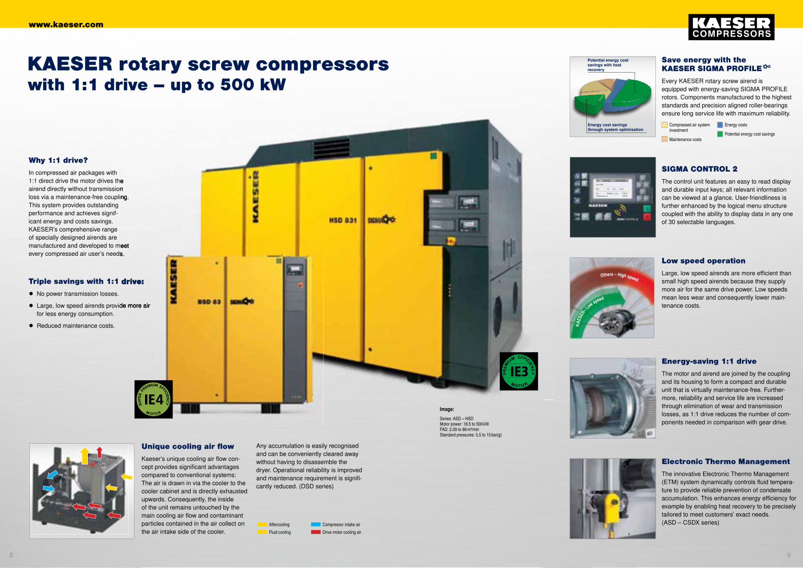
Why 1:1 drive?
In compressed air packages with 1:1 direct drive the motor drives the airend directly without transmission loss via a maintenance-free coupling. This system provides outstanding performance and achieves signif- icant energy and costs savings. KAESER’s comprehensive range of specially designed airends are manufactured and developed to meet every compressed air user’s needs.
Unique cooling air flow
Kaeser’s unique cooling air flow con-cept provides significant advantages compared to conventional systems: The air is drawn in via the cooler to the cooler cabinet and is directly exhausted upwards. Consequently, the inside of the unit remains untouched by the main cooling air flow and contaminant particles contained in the air collect on the air intake side of the cooler.
Triple savings with 1:1 drive:
● No power transmission losses.
● Large, low speed airends provide more air for less energy consumption.
● Reduced maintenance costs.
Low speed operation
Large, low speed airends are more efficient than small high speed airends because they supply more air for the same drive power. Low speeds mean less wear and consequently lower main- tenance costs.
Others – High speed
KAES
ER– L
ow speed
Aftercooling Compressor intake air
Fluid cooling Drive motor cooling air
1:1 direct drive the motor drives the airend directly without transmission loss via a maintenance-free coupling.
manufactured and developed to meet every compressed air user’s needs.
Triple savings with 1:1 drive:
Large, low speed airends provide more air
Image:
Series: ASD – HSD Motor power: 18.5 to 500 kW FAD: 2.09 to 86 m³/min Standard pressures: 5.5 to 15 bar(g)
KAESER rotary screw compressorswith 1:1 drive – up to 500 kW
Save energy with the KAESER SIGMA PROFILE
Every KAESER rotary screw airend is equipped with energy-saving SIGMA PROFILE rotors. Components manufactured to the highest standards and precision aligned roller-bearings ensure long service life with maximum reliability.
Any accumulation is easily recognised and can be conveniently cleared away without having to disassemble the dryer. Operational reliability is improved and maintenance requirement is signifi-cantly reduced. (DSD series)
Energy cost savings through system optimisation
Potential energy cost savings with heat recovery
Compressed air system investment
Maintenance costs
Energy costs
Potential energy cost savings
SIGMA CONTROL 2
The control unit features an easy to read display and durable input keys; all relevant information can be viewed at a glance. User-friendliness is further enhanced by the logical menu structure coupled with the ability to display data in any one of 30 selectable languages.
98
www.kaeser.com
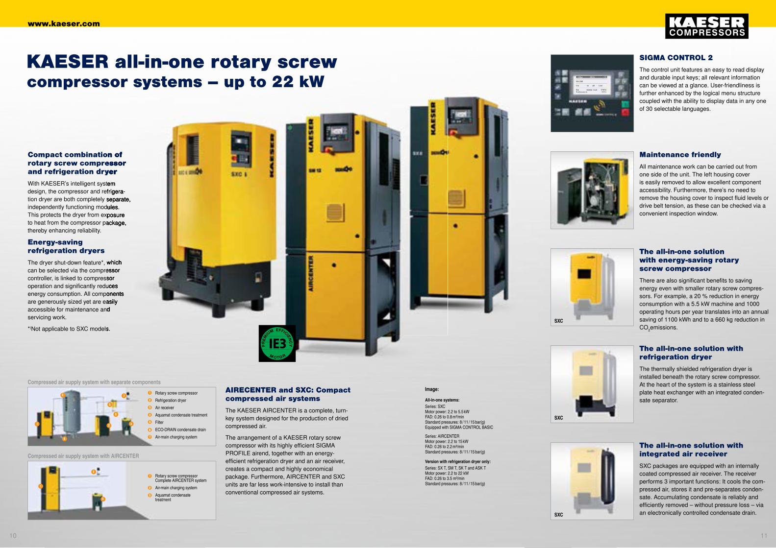
Compact combination of rotary screw compressor and refrigeration dryer
With KAESER’s intelligent system design, the compressor and refrigera-tion dryer are both completely separate, independently functioning modules. This protects the dryer from exposure to heat from the compressor package, thereby enhancing reliability.
Energy-saving refrigeration dryers
The dryer shut-down feature*, which can be selected via the compressor controller, is linked to compressor operation and significantly reduces energy consumption. All components are generously sized yet are easily accessible for maintenance and servicing work.
*)Not applicable to SXC models.
AIRECENTER and SXC: Compact compressed air systems
The KAESER AIRCENTER is a complete, turn-key system designed for the production of dried compressed air.
The arrangement of a KAESER rotary screw compressor with its highly efficient SIGMA PROFILE airend, together with an energy-efficient refrigeration dryer and an air receiver, creates a compact and highly economical package. Furthermore, AIRCENTER and SXC units are far less work-intensive to install than conventional compressed air systems.
Compressed air supply system with separate components
3 7Rotary screw compressor
Refrigeration dryer
Air receiver
Aquamat condensate treatment
Filter
ECO-DRAIN condensate drain
Air-main charging system
6
1 2 4
5
7
6
5
4
3
2
1
Rotary screw compressor Complete AIRCENTER system
Air-main charging system
Aquamat condensate treatment
Compressed air supply system with AIRCENTER
Maintenance friendly
All maintenance work can be carried out from one side of the unit. The left housing cover is easily removed to allow excellent component accessibility. Furthermore, there’s no need to remove the housing cover to inspect fluid levels or drive belt tension, as these can be checked via a convenient inspection window.
The all-in-one solution with integrated air receiver
SXC packages are equipped with an internally coated compressed air receiver. The receiver performs 3 important functions: It cools the com-pressed air, stores it and pre-separates conden-sate. Accumulating condensate is reliably and efficiently removed – without pressure loss – via an electronically controlled condensate drain.
The all-in-one solution with energy-saving rotary screw compressor
There are also significant benefits to saving energy even with smaller rotary screw compres-sors. For example, a 20 % reduction in energy consumption with a 5.5 kW machine and 1000 operating hours per year translates into an annual saving of 1100 kWh and to a 660 kg reduction in CO2emissions.
The all-in-one solution with refrigeration dryer
The thermally shielded refrigeration dryer is installed beneath the rotary screw compressor. At the heart of the system is a stainless steel plate heat exchanger with an integrated conden-sate separator.
KAESER all-in-one rotary screwcompressor systems – up to 22 kW
6
1
2
33
2
1
Image:
SXC
SXC
SXC
All-in-one systems:Series: SXC Motor power: 2.2 to 5.5 kW FAD: 0.26 to 0.8 m³/min Standard pressures: 8 / 11 / 15 bar(g) Equipped with SIGMA CONTROL BASIC
Series: AIRCENTER Motor power: 2.2 to 15 kW FAD: 0.26 to 2.2 m³/min Standard pressures: 8 / 11 / 15 bar(g)
Series: SX T, SM T, SK T and ASK T Motor power: 2.2 to 22 kW FAD: 0.26 to 3.5 m³/min Standard pressures: 8 / 11 / 15 bar(g)
Version with refrigeration dryer only:
SIGMA CONTROL 2
The control unit features an easy to read display and durable input keys; all relevant information can be viewed at a glance. User-friendliness is further enhanced by the logical menu structure coupled with the ability to display data in any one of 30 selectable languages.
Compact combination of rotary screw compressor and refrigeration dryer
With KAESER’s intelligent systemdesign, the compressor and refrigera-tion dryer are both completely separate, independently functioning modules.This protects the dryer from exposure to heat from the compressor package,
The dryer shut-down feature*, which can be selected via the compressor controller, is linked to compressoroperation and significantly reducesenergy consumption. All components are generously sized yet are easilyaccessible for maintenance and
Not applicable to SXC models.
1110
www.kaeser.com

The innovative ASD T to DSD T series
These advanced rotary screw com-pressors are versatile, reliable and highly efficient.
With an integrated refrigeration dryer module, these complete air systems provide a dependable source of quality compressed air.
Because the air compressor and refrig-eration dryer are installed in separate cabinets, the dryer is shielded from exposure to heat from the compressor package, thereby enhancing reliability.
Dependable refrigeration dryer
The refrigeration dryer is also equipped with an electronic ECO DRAIN. The level-controlled condensate drain eliminates the compressed air losses associated with solenoid valve control, which not only saves energy, but also enhances operational reliability.
Space-saving modular design
The refrigeration dryer module turns a standard rotary screw compressor into a compact com-pressed air supply system. All components are easily accessible, both simplifying and speeding up all maintenance work.
Turnkey operation
Attached to the compressor unit, the refrigeration dryer module is delivered fully connected and ready for oper- ation. The separate cabinet design allows the dryer components to be generously sized yet easily accessible and shields the dryer from exposure to heat arising from the compression process.
Efficient centrifugal separator
Installed upstream from the refrigeration dryer, the centrifugal separator ensures dependable and efficient condensate removal even under condi-tions with high ambient temperatures and relative humidity. An electronic level-sensing ECO DRAIN provides effective condensate drainage without pressure loss.
Energy saving refrigeration dryers
The dryer shut-down feature, which is linked to compressor operation, signifi-cantly reduces energy consumption.
Save energy with the KAESER SIGMA PROFILE
Every KAESER rotary screw airend is equipped with energy-saving SIGMA PROFILE rotors. Components manufactured to the highest stand-ards and precision aligned roller-bearings ensure long service life with maximum reliability.
KAESER modular rotary screwcompressors with refrigeration dryer – up to 132 kW
Image:Series: ASD T to DSD T Motor power: 18.5 to 132 kW FAD: 2.09 to 23.8 m³/min Standard pressures: 8 / 11 / 15 bar(g)
The high performance cooling system ensures reliable air pack-age operation up to an ambient temperature of +45°C.
Energy cost savings through system optimisation
Potential energy cost savings with heat recovery
Compressed air system investment
Maintenance costs
Energy costs
Energy cost saving potential
SIGMA CONTROL 2
The control unit features an easy to read display and durable input keys; all relevant information can be viewed at a glance. User-friendliness is further enhanced by the logical menu structure coupled with the ability to display data in any one of 30 selectable languages.
1312
www.kaeser.com
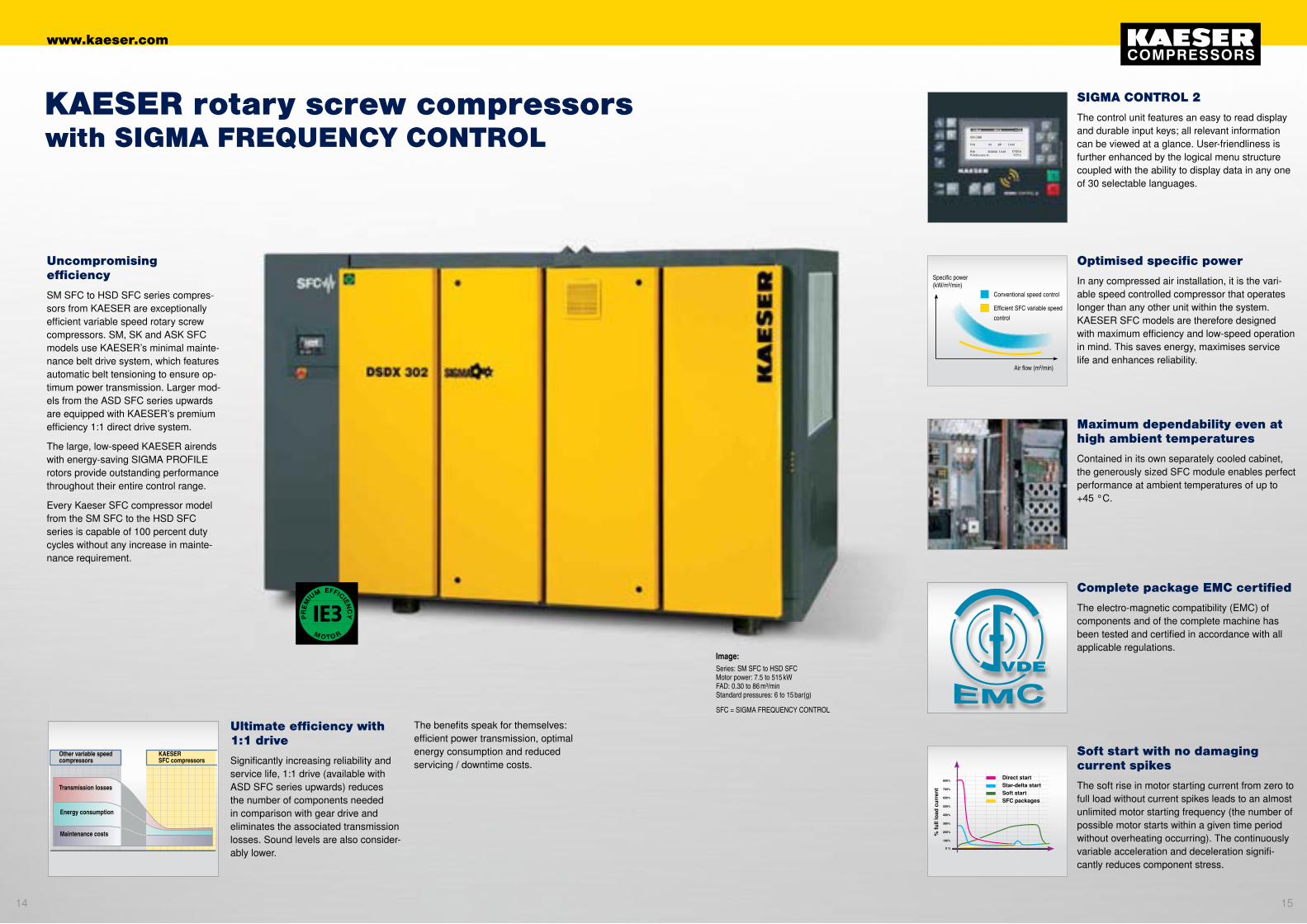
Uncompromising efficiency
SM SFC to HSD SFC series compres-sors from KAESER are exceptionally efficient variable speed rotary screw compressors. SM, SK and ASK SFC models use KAESER’s minimal mainte-nance belt drive system, which features automatic belt tensioning to ensure op-timum power transmission. Larger mod-els from the ASD SFC series upwards are equipped with KAESER’s premium efficiency 1:1 direct drive system.
The large, low-speed KAESER airends with energy-saving SIGMA PROFILE rotors provide outstanding performance throughout their entire control range.
Every Kaeser SFC compressor model from the SM SFC to the HSD SFC series is capable of 100 percent duty cycles without any increase in mainte-nance requirement.
Complete package EMC certified
The electro-magnetic compatibility (EMC) of components and of the complete machine has been tested and certified in accordance with all applicable regulations.
Maximum dependability even at high ambient temperatures
Contained in its own separately cooled cabinet, the generously sized SFC module enables perfect performance at ambient temperatures of up to +45 °C.
Optimised specific power
In any compressed air installation, it is the vari-able speed controlled compressor that operates longer than any other unit within the system. KAESER SFC models are therefore designed with maximum efficiency and low-speed operation in mind. This saves energy, maximises service life and enhances reliability.
Soft start with no damaging current spikes
The soft rise in motor starting current from zero to full load without current spikes leads to an almost unlimited motor starting frequency (the number of possible motor starts within a given time period without overheating occurring). The continuously variable acceleration and deceleration signifi-cantly reduces component stress.
Ultimate efficiency with 1:1 drive
Significantly increasing reliability and service life, 1:1 drive (available with ASD SFC series upwards) reduces the number of components needed in comparison with gear drive and eliminates the associated transmission losses. Sound levels are also consider-ably lower.
Other variable speed compressors
KAESER SFC compressors
Transmission losses
Energy consumption
Maintenance costs
800%
700%
600%
500%
400%
300%
200%
100%
0 %
% fu
ll lo
ad c
urre
nt
Direct start Star-delta start Soft start SFC packages
KAESER rotary screw compressorswith SIGMA FREQUENCY CONTROL
Image:Series: SM SFC to HSD SFC Motor power: 7.5 to 515 kW FAD: 0.30 to 86 m³/min Standard pressures: 6 to 15 bar(g)
SFC = SIGMA FREQUENCY CONTROL
The benefits speak for themselves: efficient power transmission, optimal energy consumption and reduced servicing / downtime costs.
SIGMA CONTROL 2
The control unit features an easy to read display and durable input keys; all relevant information can be viewed at a glance. User-friendliness is further enhanced by the logical menu structure coupled with the ability to display data in any one of 30 selectable languages.
Conventional speed control
Efficient SFC variable speed control
Specific power (kW/m³/min)
Air flow (m³/min)
1514
www.kaeser.com

• Quick and simple operation with clear icons and large display
• Fully automatic DUAL control (full load/ idle/ on/ off control)
• Monitoring of air network pressure parameters, airend temperature and direction of rotor rotation
• Counter for service, load and operation hours
• Adjustable service intervals, pressure and temp- erature unit selection (bar / psi / MPa / °C / °F)
• Adjustable nominal system pressure
• Adjustable switching differential
• Group alarm floating contact
• Electronic pressure transducer
SIGMA CONTROL BASIC – Functions
SIGMA CONTROL 2...
...for SX to HSD series compressors
With its versatile control, monitoring and communication abilities, the industrial PC-based SIGMA CONTROL 2 is the perfect choice for applications requiring sophis-ticated communication functionality. It is therefore fitted as standard on all KAESER ASD to HSD series rotary screw compres-sors and is optionally available for SX, SM, SK and ASK series compressors.SK and ASK series compressors.
Series: SX – HSD
Series: SXC, SX – ASK
...for SXC, SX, SM, SK and ASK
The SIGMA CONTROL BASIC is available with KAESER’s SXC, SX, SM, SK and ASK series rotary screw compressors. It is the perfect solution for users who initially require a single compres-sor for their air supply, but who also may wish to expand the compressed air system in the future. Furthermore, KAESER’s modular control and com-pressed air management concept ensures trouble-free system compatibility.
SIGMA CONTROL BASIC...
SIGMA CONTROL 2 – The function keys in detail
SIGMA CONTROL 2 and SIGMA CONTROL BASICTailored intelligence
Basic functions
Alarm icon – Red LED – indicates ‘Com-pressor alarm’. Compressor is shut down on alarm.
Communication alarm icon – Red LED – indicates ‘Data communication to other systems interrupted’.
Maintenance icon – Yellow LED – indi-cates ‘Maintenance due’ or ‘Maintenance counter expired’ or ‘Warning’.
Power ON icon – Green LED – indicates ‘Main switch ON, power supply available’.
‘Traffic light’ functions
ON key switches the compressor ‘ON’ -> automatic self control operation. Green LED indicates ‘Compressor ON’.
OFF key – switches the compressor ‘OFF’.
UP key scrolls display text line-by-line upwards.
Escape key returns to next highest menu level.
DOWN key scrolls through display text line-by-line downwards.
RIGHT key scrolls through text line-by-line to the right.
LEFT key scrolls through text line-by-line to the left.
Acknowledge key confirms alarms and – when permitted – resets the alarm memory.
Return key initiates jump to next sub-menu or accepts value.
Menu functions
Idle key switches the compressor from load to idle.
Load icon – Green LED – indicates ‘Compressor on load, air being supplied’.
Idle icon – Green LED – indicates ‘Compressor running’, ‘no air supply’.
Remote ON key – Green LED – switches remote control mode ‘ON’ and ‘OFF’.
Timer ON/OFF key – Green LED – activates / deactivates the set timer function.
Additional functions
Info key – Calls up current event information.
1716
www.kaeser.com

SIGMA AIR MANAGER: Tomorrow’s technology, today
The SIGMA AIR MANAGER (SAM) is a ground-breaking PC-based master compressed air management system that combines cutting edge Internet and web server technology within a single unit. Designed to optimise compressor system operation, it minimises power requirement by automatically selecting the most favourable machine configura-tion from up to 16 compressors. The SAM uses Kaeser’s adaptive 3-D Control which considers the three crucial factors that affect energy-efficient compressor control within a compressed air station, namely: switching losses, control losses and pressure flexibility. In order to ensure optimum performance, the SAM constantly analyses the relationship between these factors, calculates the best possible result and controls the compressors accordingly. Moreover, this approach enables required system pressure to be reduced thereby achieving further significant savings - each 1 bar decrease in pressure results in a 6 percent energy saving.
The SIGMA AIR CONTROL data visu-alisation feature, integrated as standard in every SIGMA AIR MANAGER master controller, allows current operational data, messages and alarms to be viewed at any time via the Internet simply by using a standard browser and requires no ad-ditional software.
Long-term data storage and compressed air auditing functionality is also available via SIGMA AIR CONTROL PLUS (option).
Information technology –Tailored system solutions
Compressed air station
1
2
3
4
5
6
7
8
9
10
11
12
@Telephone network
Ethernet
RS 232
Send maintenance / alarm messages via SMS to your personal mobile telephone number
The internal SIGMA CONTROL 2 compressor controller forms the basis for comprehensive system monitoring and management. Data exchange between the SIGMA CONTROL 2 and SIGMA AIR MANAGER is performed via the Profibus DP interface.
GSM modem
3
12
12
12
12
22
1
4
5
6
7
8
9
10
Rotary screw compressor • With energy-saving motor for minimised energy costs • Highly efficient SIGMA PROFILE ensures more air for less energy consumption
SIGMA CONTROL compressor controller • Proven industrial PC • Future compatible with update capability • Exceptional versatility, even allows connection of external components (e.g. refrigeration dryer) • Prepared for Teleservice and connection of control and communication systems (Profibus DP) as standard • Powerful multi-function timer
SIGMA AIR MANAGER compressed air management system
Refrigeration dryer • Ensures quality, dry compressed air • Condensate-free compressed air • Pressure dew point +3 °C • SECOTEC CONTROL enables energy savings of up to 90%.
Air filters • For clean compressed air • Minimal pressure drop
Integrated KAESER centrifugal seprator • Consistent degree of separation
Air receiver • Galvanised both internally and externally as per DIN 50976 • Long service life
Condensate drain • Automatic electronic-controlled condensate drain • Unrivalled reliability • No compressed air losses
Oil / water separation system • Treats compressor condensate • Complies with applicable water regulations • Approved by the Berlin Structural Engineering Institute • Saves disposal costs
Air-main charging system • Treated compressed air even when network is depressurised • Significantly reduced leakage losses
Visualisation and long-term analysis with SIGMA AIR CONTROL basic and SIGMA AIR CONTROL plus (optional)
• Long-term data measurement for reporting, analysis, control and audits • Enables targeted compressed air cost reduction • Highly informative energy cost summaries • Additional cost pools can be added • No additional software required (system uses standard Internet browser) • Visualisation via RS 232 / Intranet / telephone network • Real-time data online
Communication System data stored and processed in the SIGMA AIR MANAGER can be transferred via telephone or computer network (Ethernet). SMS messages, for example, can be forwarded to a service technician’s mobile telephone.
11
2
2
1918
www.kaeser.com
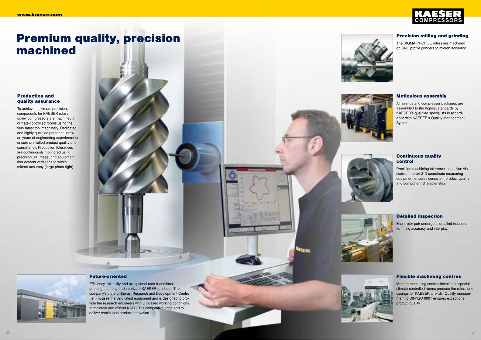
Premium quality, precision machined
Meticulous assembly
All airends and compressor packages are assembled to the highest standards by KAESER’s qualified specialists in accord-ance with KAESER’s Quality Management System.
Precision milling and grinding
The SIGMA PROFILE rotors are machined on CNC profile grinders to micron accuracy.
Continuous quality control
Precision machining tolerance inspection via state-of-the-art 3-D coordinate measuring equipment ensures consistent product quality and component characteristics.
Detailed inspection
Each rotor pair undergoes detailed inspection for fitting accuracy and interplay.
Flexible machining centres
Modern machining centres installed in special climate-controlled rooms produce the rotors and casings for KAESER airends. Quality manage-ment to DIN/ISO 9001 ensures exceptional product quality.
Future-oriented
Efficiency, reliability and exceptional user-friendliness are long-standing trademarks of KAESER products. The company’s state-of-the-art Research and Development Centre (left) houses the very latest equipment and is designed to pro-vide the research engineers with unrivalled working conditions to maintain and extend KAESER’s competitive edge and to deliver continuous product innovation.
Production and quality assurance
To achieve maximum precision, components for KAESER rotary screw compressors are machined in climate-controlled rooms using the very latest tool machinery. Dedicated and highly qualified personnel draw on years of engineering experience to ensure unrivalled product quality and consistency. Production tolerances are continuously monitored using precision 3-D measuring equipment that detects variations to within micron accuracy (large photo right).
2120
www.kaeser.com

Global service and advice
KAESER is represented throughout the world by in-country subsidiaries and qualified partners. No matter where, our customers can rely on fast, dependable customer support- and the same applies for service and maintenance.
SIGMA AIR UTILITY:
SIGMA AIR UTILITY – Just buy the air you need. Now you can buy compressed air at a fixed price per unit, just like electricity, or any other utility.
Optimised air supplies
After carrying out a computer-aided Air Demand Analysis (ADA), we will quickly determine your business’s compressed air demand and provide an exact itemised air-cost analysis. With help from KAESER’s Energy Saving System (KESS), the ADA data forms the basis for determining a cost-optimised air supply solution.
Outstanding customer service
Our goal is total customer satisfaction, which is why we have created a worldwide service net-work providing global customer support. Expert service technicians and engineers are available throughout the world to give fast, reliable help where you need it, when you need it.
Worldwide Teleservice
KAESER Teleservice, a cost-saving service solution based on global networking and data communication, enables remote diagnosis and demand-oriented maintenance. The service provides improved availability and optimised overall air supply efficiency.
Genuine KAESER parts
KAESER’s service personnel use only genu-ine maintenance and spare parts with proven long-term quality to ensure unrivalled reliability and long service life. Only Kaeser original parts guarantee tested quality.
Expert advice and professional customer care: KAESER AIR SERVICEKAESER AIR SERVICE
Global service and advice
KAESER is represented throughout the world by in-country subsidiaries and qualified partners. No matter where, our customers can rely on fast, dependable customer support- and the same applies for service and maintenance.
2322
www.kaeser.com
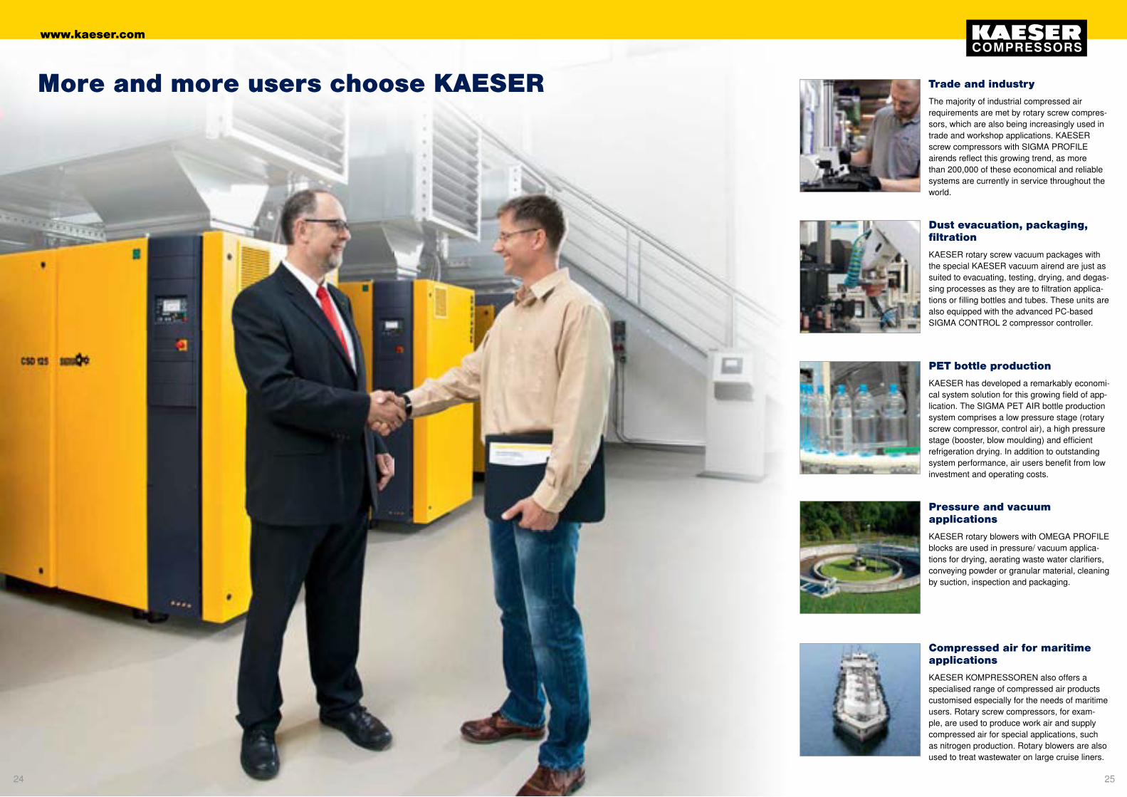
Compressed air for maritime applications
KAESER KOMPRESSOREN also offers a specialised range of compressed air products customised especially for the needs of maritime users. Rotary screw compressors, for exam-ple, are used to produce work air and supply compressed air for special applications, such as nitrogen production. Rotary blowers are also used to treat wastewater on large cruise liners.
Trade and industry
The majority of industrial compressed air requirements are met by rotary screw compres-sors, which are also being increasingly used in trade and workshop applications. KAESER screw compressors with SIGMA PROFILE airends reflect this growing trend, as more than 200,000 of these economical and reliable systems are currently in service throughout the world.
Dust evacuation, packaging, filtration
KAESER rotary screw vacuum packages with the special KAESER vacuum airend are just as suited to evacuating, testing, drying, and degas-sing processes as they are to filtration applica-tions or filling bottles and tubes. These units are also equipped with the advanced PC-based SIGMA CONTROL 2 compressor controller.
PET bottle production
KAESER has developed a remarkably economi-cal system solution for this growing field of app- lication. The SIGMA PET AIR bottle production system comprises a low pressure stage (rotary screw compressor, control air), a high pressure stage (booster, blow moulding) and efficient refrigeration drying. In addition to outstanding system performance, air users benefit from low investment and operating costs.
Pressure and vacuum applications
KAESER rotary blowers with OMEGA PROFILE blocks are used in pressure/ vacuum applica-tions for drying, aerating waste water clarifiers, conveying powder or granular material, cleaning by suction, inspection and packaging.
More and more users choose KAESER
2524
www.kaeser.com

Modell Betriebs-über-druck
bar
Liefermenge*) Gesamtanlage bei Betriebs-
überdruck
m³/min
max.Über-druck
bar
Motor-nenn-
leistung
kW
AbmessungenB x T x H
mm
AnschlussDruckluft
Schalldruck--pegel **)
dB(A)
Masse
kg
SX 3 7.510
0.340.26
811 2.2 590 x 632 x 970
G 3/4
59 140
SX 47.51013
0.450.36 0.26
81115
3 590 x 632 x 970 60 140
SX 67.51013
0.600.480.37
81115
4 590 x 632 x 970 61 145
SX 87.51013
0.800.670.54
81115
5.5 590 x 632 x 970 64 155
SM 97.51013
0.900.750.56
81115
5.5 630 x 762 x 1100
G 3/4
64 200
SM 127.51013
1.201.010.77
81115
7.5 630 x 762 x 1100 65 210
SM 157.51013
1.501.260.99
81115
9 630 x 762 x 1100 66 220
SK 227.51013
2.001.681.32
81115
11 750 x 895 x 1260
G 1
66 312
SK 257.51013
2.502.111.72
81115
15 750 x 895 x 1260 67 320
ASK 287.51013
2.862.401.93
81115
15 800 x 1100 x 1530
G 1 1/4
65 485
ASK 347.51013
3.513.002.50
81115
18.5 800 x 1100 x 1530 67 505
ASK 407.51013
4.063.522.94
81115
22 800 x 1100 x 1530 69 525
Modell Betriebs-über-druck
bar
Liefermenge*) Gesamtanlage bei Betriebs-
überdruck
m³/min
max.Über-druck
bar
Motor-nenn-
leistung
kW
AbmessungenB x T x H
mm
AnschlussDruckluft
Schalldruck--pegel **)
dB(A)
Masse
kg
ASD 35 7.510
3.162.63
8.512 18.5 1460 x 900 x 1530
G 1 1/4
65 610
ASD 407.51013
3.923.132.58
8.51215
22 1460 x 900 x 1530 66 655
ASD 507.51013
4.583.853.05
8.51215
25 1460 x 900 x 1530 66 695
ASD 607.51013
5.534.493.71
8.51215
30 1460 x 900 x 1530 69 750
BSD 657.51013
5.654.523.76
8.51215
30 1590 x 1030 x 1700
G 1 1/2
69 970
BSD 757.51013
7.005.604.43
8.51215
37 1590 x 1030 x 1700 70 985
BSD 837.51013
8.166.855.47
8.51215
45 1590 x 1030 x 1700 71 1060
CSD 857.51013
8.266.895.50
8.51215
45 1760 x 1110 x 1900
G 2
70 1250
CSD 1057.51013
10.148.186.74
8.51215
55 1760 x 1110 x 1900 71 1290
CSD 1257.51013
12.0210.048.06
8.51215
75 1760 x 1110 x 1900 72 1320
CSDX 1407.51013
13.7411.839.86
8.51215
75 2110 x 1290 x 1950
G 2
71 1830
CSDX 1657.51013
16.1613.5311.49
8.51215
90 2110 x 1290 x 1950 72 1925
Rotary screw compressors with V-belt drive – to 22 kW
SX – ASK series
Model Working pressure
bar
FAD *) Overall package
at working pressure
m³/min
Max.operatingpressure
bar
Rated motorpower
kW
Dimensions W x D x H
mm
Air connection
Sound pressure level **)
dB(A)
Weight
kg
Model Working pressure
bar
FAD *) Overall package
at working pressure
m³/min
Max.operatingpressure
bar
Rated motorpower
kW
Dimensions W x D x H
mm
Airconnection
Sound pressure level **)
dB(A)
Weight
kg
Rotary screw compressors with 1:1 drive – to 90 kW
ASD – CSDX series
*) Performance data in accordance with ISO 1217: 2009, Annex C.**) Sound pressure level as per ISO 2151 and basic standard ISO 9614-2, tolerance: ± 3 dB(A). ***) At high fan speed *) Performance data in accordance with ISO 1217: 2009, Annex C.**) Sound pressure level as per ISO 2151 and basic standard ISO 9614-2, tolerance: ± 3 dB(A). ***) At high fan speed
2726
www.kaeser.com
Modell Betriebs-über-druck
Liefermenge*) Gesamtanlage bei Betriebs-
überdruck
max.Über-druck
Motor-nenn-
leistung
AbmessungenB x T x H
AnschlussDruckluft
Schalldruck--pegel **)
Masse
bar m³/min bar kW mm dB(A) kg
DSD 142 7.5 13.62 9 75 2350 x 1730 x 2040
DN 65
68 2700
DSD 172 7.510
16.1213.20
8.512 90 2350 x 1730 x 2040 69 2850
DSD 2027.51013
20.4615.5212.68
8.51215
110 2350 x 1730 x 2040 70 3200
DSD 2387.51013
23.8019.9214.80
8.51215
132 2350 x 1730 x 2040 71 3400
DSDX 2437.51013
24.1020.1214.90
8.51215
132 2600 x 1980 x 2040
DN 80
7078 ***) 3650
DSDX 3027.51013
30.2023.5019.52
8.51215
160 2600 x 1980 x 2040 7178 ***) 4100
ESD 3527.51013
36.2029.7223.10
8.51215
200 2800 x 2000 x 2140
DN 125
75 4935
ESD 4427.51013
42.2035.4028.92
8.51215
250 2800 x 2000 x 2140 76 5000
FSD 4717.51012
47.1040.5035.50
81012
250 3000 x 2143 x 2360
DN 125
79 6625
FSD 5717.51013
57.2046.4039.45
81215
315 3000 x 2143 x 2360 79 6900
HSD 6517.51013
66.153.443.0
8.51215
360 3470 x 2145 x 2350
DN 150
71 8100
HSD 7117.51013
71.859.446.2
8.51215
400 3470 x 2145 x 2350 72 8500
HSD 7617.51013
77.665.152.3
8.51215
450 3470 x 2145 x 2350 72 8600
HSD 8317.51013
83.470.858.4
8.51215
500 3470 x 2145 x 2350 73 8700
Modell Betriebs-über-druck
Liefermenge*) Gesamtanlage bei Betriebs-
überdruck
max.Über-druck
Motor-nenn-
leistung
Kältetrockner Leistungs-aufnahme
Kälte-mittel
Druck-tau-
punkt
Druck-behälter-
inhalt
AbmessungenB x T x H
AnschlussDruckluft
Schall-druck--
pegel **)
Masse
bar m³/min bar kW kW Typ °C l mm dB(A) kg
SXC 3 7.510
0.340.26
811 2.2 0.18 R 134a + 6 215 620 x 980 x 1480
G 3/4
68 285
SXC 47.51013
0.450.360.26
81115
3.0 0.18 R 134a + 6 215 620 x 980 x 1480 69 285
SXC 67.51013
0.600.480.37
81115
4.0 0.26 R 134a + 6 215 620 x 980 x 1480 69 290
SXC 87.51013
0.800.670.54
81115
5.5 0.26 R 134a + 6 215 620 x 980 x 1480 69 300
AIRCENTER 3 7.510
0.340.26
811 2.2 0.18 R 134a + 3 200 590 x 1090 x 1560
G 3/4
59 285
AIRCENTER 47.51013
0.450.360.26
81115
3 0.18 R 134a + 3 200 590 x 1090 x 1560 60 285
AIRCENTER 67.51013
0.600.480.37
81115
4 0.26 R 134a + 3 200 590 x 1090 x 1560 61 290
AIRCENTER 87.51013
0.800.670.54
81115
5.5 0.26 R 134a + 3 200 590 x 1090 x 1560 64 300
AIRCENTER 97.51013
0.900.750.56
81115
5.5 0.31 R 134a + 3 270 630 x 1200 x 1716
G 3/4
64 390
AIRCENTER 127.51013
1.201.010.77
81115
7.5 0.31 R 134a + 3 270 630 x 1200 x 1716 65 400
AIRCENTER 157.51013
1.501.260.99
81115
9 0.32 R 134a + 3 270 630 x 1200 x 1716 66 410
AIRCENTER 227.51013
2.001.681.32
81115
11 0.46 R 134a + 3 350 750 x 1370 x 1880
G 1
66 579
AIRCENTER 257.51013
2.502.111.72
81115
15 0.46 R 134a + 3 350 750 x 1370 x 1880 67 587
Model Working pressure
FAD *) Overall package
at working pressure
Max.operatingpressure
Rated motorpower
Dimensions W x D x H
Airconnection
Sound pressure level **)
Weight
bar m³/min bar kW mm dB(A) kg
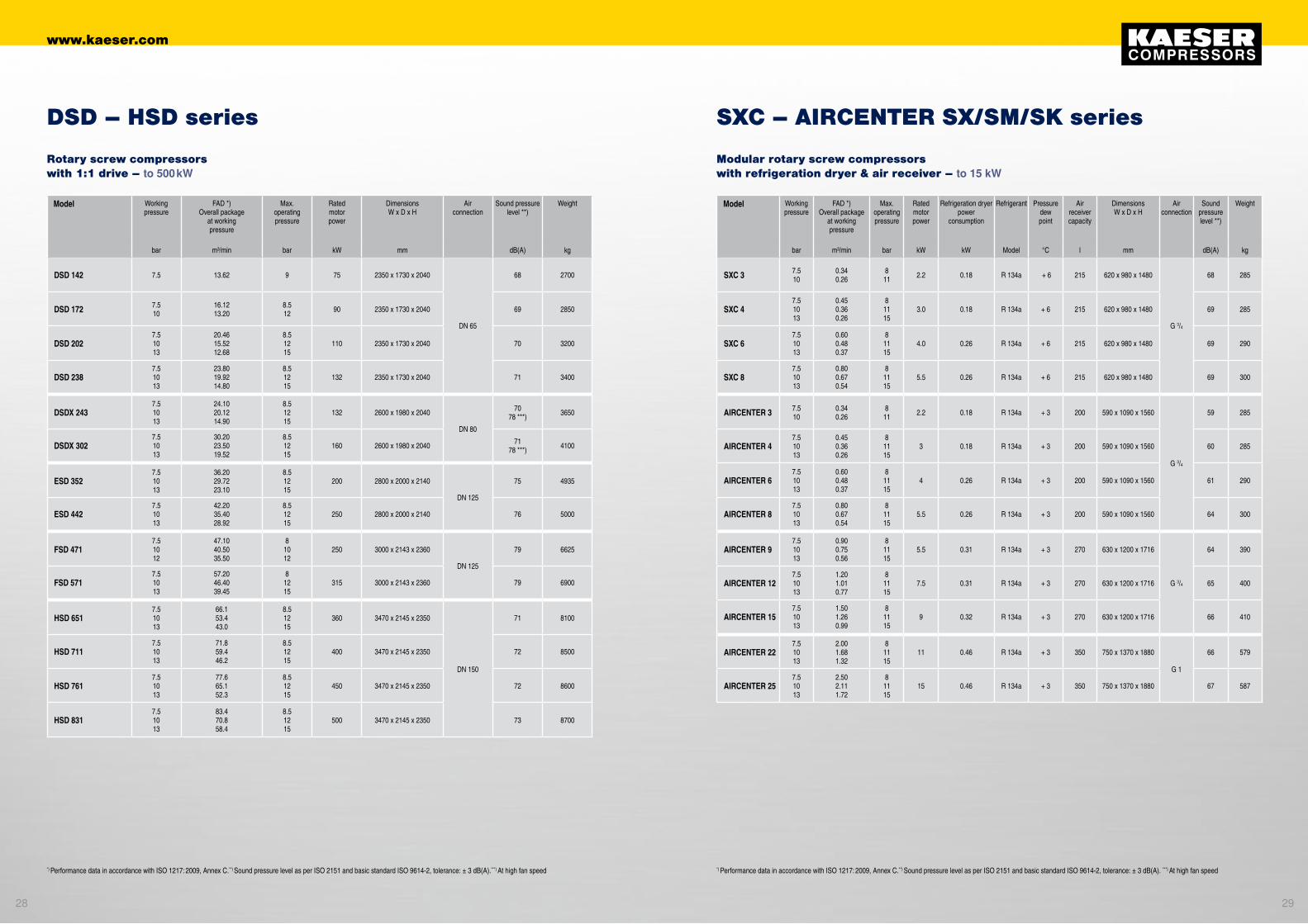
Rotary screw compressors with 1:1 drive – to 500 kW
DSD – HSD series
Model Working pressure
FAD *) Overall package
at working pressure
Max.operatingpressure
Rated motorpower
Refrigeration dryer power
consumption
Refrigerant Pressuredewpoint
Air receiver capacity
Dimensions W x D x H
Air connection
Sound pressure level **)
Weight
bar m³/min bar kW kW Model °C l mm dB(A) kg
Modular rotary screw compressors with refrigeration dryer & air receiver – to 15 kW
SXC – AIRCENTER SX/SM/SK series
*) Performance data in accordance with ISO 1217: 2009, Annex C.**) Sound pressure level as per ISO 2151 and basic standard ISO 9614-2, tolerance: ± 3 dB(A).***) At high fan speed *) Performance data in accordance with ISO 1217: 2009, Annex C.**) Sound pressure level as per ISO 2151 and basic standard ISO 9614-2, tolerance: ± 3 dB(A). ***) At high fan speed
2928
www.kaeser.com

Modell Betriebs-über-druck
Liefermenge*) Gesamtanlage bei Betriebs-
überdruck
max.Über-druck
Motor-nenn-
leistung
Kältetrockner Leistungs-aufnahme
Kälte-mittel
Druck-tau-
punkt
AbmessungenB x T x H
AnschlussDruckluft
Schall-druck--
pegel **)
Masse
bar m³/min bar kW kW Typ °C mm dB(A) kg
SX 3 T 7.510
0.340.26
811 2.2 0.18 R 134a + 3 590 x 905 x 970
G 3/4
59 185
SX 4 T7.51013
0.450.360.26
81115
3 0.18 R 134a + 3 590 x 905 x 970 60 185
SX 6 T7.51013
0.600.480.37
81115
4 0.26 R 134a + 3 590 x 905 x 970 61 190
SX 8 T7.51013
0.800.670.54
81115
5.5 0.26 R 134a + 3 590 x 905 x 970 64 200
SM 9 T7.51013
0.900.750.56
81115
5.5 0.31 R 134a + 3 630 x 1074 x 1100
G 3/4
64 275
SM 12 T7.51013
1.201.010.77
81115
7.5 0.31 R 134a + 3 630 x 1074 x 1100 65 285
SM 15 T7.51013
1.501.260.99
81115
9 0.32 R 134a + 3 630 x 1074 x 1100 66 295
SK 22 T7.51013
2.001.681.32
81115
11 0.46 R 134a + 3 750 x 1240 x 1260
G 1
66 387
SK 25 T7.51013
2.502.111.72
81115
15 0.46 R 134a + 3 750 x 1240 x 1260 67 395
ASK 28 T7.51013
2.862.401.93
81115
15 0.70 R 134a + 3 800 x 1460 x 1530
G 1 1/4
65 580
ASK 34 T7.51013
3.513.002.50
81115
18.5 0.70 R 134a + 3 800 x 1460 x 1530 67 600
ASK 40 T7.51013
4.063.522.94
81115
22 0.70 R 134a + 3 800 x 1460 x 1530 69 620
Modell Betriebs-über-druck
Liefermenge*) Gesamtanlage bei Betriebs-
überdruck
max.Über-druck
Motor-nenn-
leistung
Kältetrockner Leistungs-aufnahme
Kälte-mittel
Druck-tau-
punkt
AbmessungenB x T x H
AnschlussDruckluft
Schall-druck--
pegel **)
Masse
bar m³/min bar kW kW Typ °C mm dB(A) kg
ASD 35 T 7.510
3.162.63
8.512 18.5 0.8 R 134a + 3 1770 x 900 x 1530
G 1 1/4
65 705
ASD 40 T7.51013
3.923.132.58
8.51215
22 0.8 R 134a + 3 1770 x 900 x 1530 66 750
ASD 50 T7.51013
4.583.853.05
8.51215
25 0.8 R 134a + 3 1770 x 900 x 1530 66 790
ASD 60 T7.51013
5.534.493.71
8.51215
30 0.8 R 134a + 3 1850 x 921 x 1505 69 845
BSD 65 T7.51013
5.654.523.76
8.51215
30 0.8 R 134a + 3 1990 x 1030 x 1700
G 1 1/2
69 1100
BSD 75 T7.51013
7.005.604.43
8.51215
37 0.8 R 134a + 3 1990 x 1030 x 1700 70 1115
BSD 83 T7.51013
8.166.855.47
8.51215
45 0.8 R 134a + 3 1990 x 1030 x 1700 71 1190
CSD 85 T7.51013
8.266.895.50
8.51215
45 0.8 R 134a + 3 2160 x 1110 x 1900
G 2
70 1410
CSD 105 T7.51013
10.148.186.74
8.51215
55 0.8 R 134a + 3 2160 x 1110 x 1900 71 1450
CSD 125 T7.51013
12.0210.048.06
8.51215
75 1.1 R 134a + 3 2160 x 1110 x 1900 72 1510
CSDX 140 T7.51013
13.7411.839.86
8.51215
75 1.2 R 134a + 3 2510 x 1290 x 1950
G 2
71 2045
CSDX 165 T7.51013
16.1613.5311.49
8.51215
90 1.2 R 134a + 3 2510 x 1290 x 1950 72 2140
DSD 142 T 7.5 13.62 9 75 2.1 R 134a + 3 3310 x 1730 x 2040 68 3100
DSD 172 T 7.510
16.1213.20
8.512 90 2.1 R 134a + 3 3310 x 1730 x 2040
DN 65
69 3250
DSD 202 T7.51013
20.4615.5212.68
8.51215
110 2.35 R 134a + 3 3310 x 1730 x 2040 70 3650
DSD 238 T7.51013
23.8019.9214.80
8.51215
132 2.35 R 134a + 3 3310 x 1730 x 2040 7179***) 3850
Model Working pressure
FAD *) Overall package
at working pressure
Max.operatingpressure
Rated motorpower
Refrigeration dryer power
consumption
Refrigerant Pressuredewpoint
Dimensions W x D x H
Air connection
Sound pressure level **)
Weight
bar m³/min bar kW kW Model °C mm dB(A) kg
Modular rotary screw compressors with refrigeration dryer – to 22 kW
SX – ASK T series
Model Working pressure
FAD *) Overall package
at working pressure
Max.operatingpressure
Rated motorpower
Refrigeration dryer power
consumption
Refrigerant Pressuredewpoint
Dimensions W x D x H
Air connection
Sound pressure level **)
Weight
bar m³/min bar kW kW Model °C mm dB(A) kg
Modular rotary screw compressors with refrigeration dryer – to 132 kW
ASD – DSD T series
*) Performance data in accordance with ISO 1217: 2009, Annex C.**) Sound pressure level as per ISO 2151 and basic standard ISO 9614-2, tolerance: ± 3 dB(A). ***) At high fan speed *) Performance data in accordance with ISO 1217: 2009, Annex C.**) Sound pressure level as per ISO 2151 and basic standard ISO 9614-2, tolerance: ± 3 dB(A). ***) At high fan speed
3130
www.kaeser.com
Modell Betriebs-über-druck
Liefermenge*) Gesamtanlage bei Betriebs-
überdruck
max.Über-druck
Motor-nenn-
leistung
min.Druck-
bandbreite
Drehzahl-bereich
min. – max.
Frequenz-bereich
min. – max
AbmessungenB x T x H
AnschlussDruckluft
Schall-druck--
pegel **)
Masse
bar m³/min bar kW bar U/min Hz mm dB(A) kg
SM 12 SFC7.51013
0.35 - 1.240.34 - 1.040.30 - 0.78
81115
7.5 ± 0.11200 - 37801500 - 37801800 - 3780
20 - 6325 - 6330 - 63
630 x 762 x 1100 G 3/4 67 220
SK 22 SFC7.51013
0.62 - 1.980.63 - 1.670.57 - 1.37
81115
11 ± 0.11200 - 35101500 - 35521800 - 3660
20 - 58.525 - 59.230 - 61.0
750 x 895 x 1260
G 1
67 329
SK 25 SFC7.51013
0.81 - 2.550.84 - 2.250.83 - 1.90
81115
15 ± 0.11200 - 36601500 - 36961800 - 3872
20 - 61.025 - 61.630 - 64.5
750 x 895 x 1260 68 337
ASK 34 SFC7.51013
0.94 - 3.600.80 - 3.140.88 - 2.70
81115
18.5 ± 0.11060 - 36911075 - 37521420 - 3865
17.9 - 62.318.2 - 63.424.0- 65.3
800 x 1100 x 1530
G 1 1/4
68 530
ASK 40 SFC7.51013
0.94 - 4.190.80 - 3.710.88 - 3.17
81115
22 ± 0.1900 - 3692900 - 3741
1200 - 3870
15.2 - 62.415.2 - 63.220.3 - 65.4
800 x 1100 x 1530 70 550
ASD 50 SFC7.51013
1.05 - 5.181.00 - 4.520.92 - 3.76
8.51313
25 ± 0.1750 - 3373900 - 3500900 - 3050
25 - 113.630 - 117.830 - 102.7
1540 x 900 x 1530
G 1 1/4
68 735
ASD 60 SFC7.51013
1.26 - 6.041.00 - 4.700.92 - 4.08
8.51515
30 ± 0.1750 - 3260900 - 3700900 - 3316
25 - 109.8 30 - 124.6 30 - 111.6
1540 x 900 x 1530 70 795
BSD 75 SFC7.51013
1.54 - 7.351.52 - 6.471.16 - 5.50
101015
37 ± 0.1900 - 3888900 - 3430900 - 3690
15 - 65.515 - 57.715 - 62.1
1665 x 1030 x 1700 G 1 1/2 72 1070
CSD 85 SFC7.51013
1.95 - 8.081.48 - 6.911.07 - 5.92
8.51215
45 ± 0.1900 - 3492900 - 3730900 - 4020
15 - 58.215 - 62.215 - 67
1760 x 1110 x 1900
G 2
72 1260
CSD 105 SFC7.51013
2.19 - 9.851.90 - 8.351.36 - 6.88
8.51215
55 ± 0.1900 - 3606900 - 3690900 - 3840
15 - 60.115 - 61.515 - 64
1760 x 1110 x 1900 73 1380
CSD 125 SFC7.51013
2.84 - 12.002.05 - 10.531.79 - 8.75
8.51215
75 ± 0.1900 - 3624900 - 3900900 - 4020
15 - 60.415 - 6515 - 67
1760 x 1110 x 1900 74 1400
CSDX 140 SFC7.51013
3.39 - 13.172.81 - 11.331.90 - 9.73
8.51215
75 ± 0.1900 - 3330 900 - 3410900 - 3660
15 - 55.515 - 56.815 - 61
2110 x 1290 x 1950
G 2
72 1835
CSDX 165 SFC7.51013
3.84 - 15.843.29 - 13.842.70 - 11.70
8.51215
90 ± 0.1900 - 3486900 - 3590900 - 3660
15 - 58.115 - 59.815 - 61
2110 x 1290 x 1950 73 2025
Modell Betriebs-über-druck
Liefermenge*) Gesamtanlage bei Betriebs-
überdruck
max.Über-druck
Motor-nenn-
leistung
min.Druck-
bandbreite
Drehzahl-bereich
min. – max.
Frequenz-bereich
min. – max
AbmessungenB x T x H
AnschlussDruckluft
Schall-druck--
pegel **)
Masse
bar m³/min bar kW bar U/min Hz mm dB(A) kg
DSD 142 SFC 7.5 3.60 - 14.80 9 75 ± 0.1 450 - 1635 15 - 54.5 2905 x 1730 x 2040
DN 65
69 3100
DSD 172 SFC7.510
3.60 - 16.333.55 - 14.20 10 90 ± 0.1 450 - 1815
450 - 159015 - 60.515 - 53 2905 x 1730 x 2040 70 3230
DSD 202 SFC7.51013
4.25 - 20.304.00 - 17.303.25 - 14.95
101015
110 ± 0.1450 - 1905450 - 1680450 -1770
15 - 63.515 - 5615 - 59
2905 x 1730 x 2040 71 3730
DSD 238 SFC7.51013
5.93 - 22.505.80 - 20.003.56 - 16.00
101015
132 ± 0.1450 - 1650450 - 1500450 - 1620
15 - 5515 - 5015 - 54
2905 x 1730 x 2040 72 (79***) 3870
DSDX 243 SFC7.51013
6.62 - 26.905.60 - 23.733.56 - 19.00
8.51215
132 ± 0.1450 - 1680450 - 1770450 - 1920
15 - 5615 - 5915 - 64
3155 x 1945 x 2040
DN 80
71 (78***) 4150
DSDX 302 SFC7.51013
6.62 - 30.605.60 - 26.703.56 - 21.10
8.51215
160 ± 0.1450 - 1920450 - 2010450 - 2160
15 - 6415 - 6715 - 72
3155 x 1945 x 2040 72 (78***) 4600
ESD 352 SFC7.51013
8.58 - 33.386.43- 27.435.17 - 23.70
8.51215
200 ± 0.1450 - 1668 450 - 1730450 - 1800
15 - 55.615 - 57.715 - 60
3100 x 2000 x 2140
DN 125
76 4848
ESD 442 SFC7.51013
10.14 - 41.528.33 - 36.006.13 - 29.50
8.51215
250 ± 0.1450 - 1746450 - 1870450 - 1920
15 - 58.215 - 62.315 - 64.0
3100 x 2000 x 2140 77 4876
FSD 571 SFC7.51013
13.30 - 52.159.80 - 45.109.40 - 39.70
8.51515
315 ± 0.1450 - 1665450 - 1920450 - 1710
15 - 55.515 - 6415 - 57
3610 x 2143 x 2360 DN 125 80 7610
HSD 651 SFC7.510
10.1 - 66.08.4 - 56.1
8.512 382 ± 0.1
450 - 1770450 - 1830
15 - 5915 - 61 4370 x 2145 x 2350
DN 150
73 9100
HSD 761 SFC7.51013
11.7 - 75.99.8 - 63.88.0 - 54.0
8.51215
410 ± 0.1450 - 1650450 - 1710450 - 1770
15 - 5515 - 5715 - 59
4370 x 2145 x 2350 74 9600
HSD 831 SFC7.51013
11.8 - 86.09.8 - 73.69.4 - 62.6
81215
515 ± 0.1450 - 1830450 - 1890450 - 1710
15 - 6115 - 6315 - 57
4370 x 2145 x 2350 75 10100
Model Working pressure
FAD *) Overall package
at working pressure
Max.operatingpressure
Rated motorpower
Min. pressure
bandwidth
Speed range
min. – max.
Frequency range
min. – max.
Dimensions W x D x H
Air connection
Sound pressure level **)
Weight
bar m³/min bar kW bar rpm Hz mm dB(A) kg
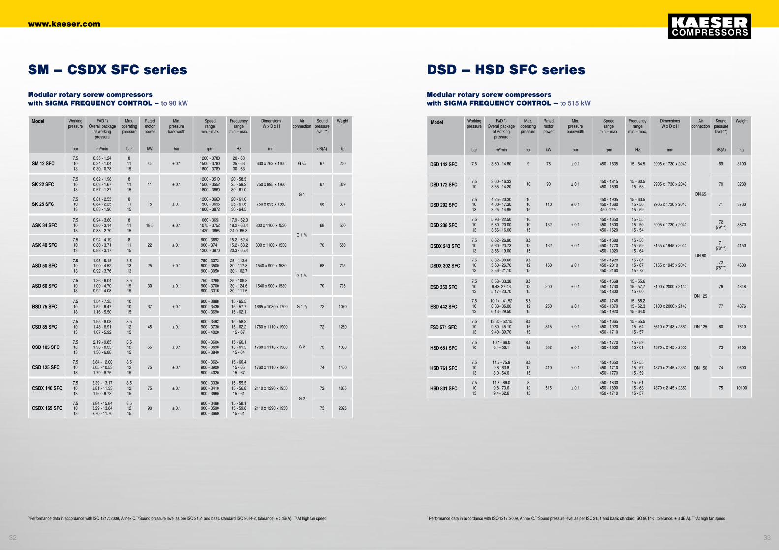
Modular rotary screw compressors with SIGMA FREQUENCY CONTROL – to 90 kW
SM – CSDX SFC series
Modular rotary screw compressors with SIGMA FREQUENCY CONTROL – to 515 kW
DSD – HSD SFC series
Model Working pressure
FAD *) Overall package
at working pressure
Max.operatingpressure
Rated motorpower
Min. pressure
bandwidth
Speed range
min. – max.
Frequency range
min. – max.
Dimensions W x D x H
Airconnection
Sound pressure level **)
Weight
bar m³/min bar kW bar rpm Hz mm dB(A) kg
*) Performance data in accordance with ISO 1217: 2009, Annex C.**) Sound pressure level as per ISO 2151 and basic standard ISO 9614-2, tolerance: ± 3 dB(A). ***) At high fan speed *) Performance data in accordance with ISO 1217: 2009, Annex C.**) Sound pressure level as per ISO 2151 and basic standard ISO 9614-2, tolerance: ± 3 dB(A). ***) At high fan speed
3332
www.kaeser.com

Modell Betriebs-über-druck
Liefermenge*) Gesamtanlage bei Betriebs-
überdruck
max.Über-druck
Motor-nenn-
leistung
Drehzahl-bereich
min. – max.
Frequenz-bereich
min. – max
Kältetrockner Leistungs-aufnahme
Kälte-mittel
Druck-tau-
punkt
AbmessungenB x T x H
AnschlussDruckluft
Schall-druck--
pegel **)
Masse
bar m³/min bar kW U/min Hz KW Typ °C mm dB(A) kg
AIRCENTER 12 SFC7.51013
0.34 - 1.240.34 - 1.040.30 - 0.78
81115
7.51200 - 37801500 - 37801800 - 3780
20 - 6325 - 6330 - 63
0.31 R 134a + 3 630 x 1200 x 1716 G 3/4 67 410
AIRCENTER 22 SFC7.51013
0.62 - 1.980.63 - 1.670.57 - 1.37
81115
111200 - 35101500 - 35521800 - 3660
20 - 58.525 - 59.230 - 61.0
0.46 R 134a + 3 750 x 1370 x 1880 G 1 67 596
AIRCENTER 25 SFC7.51013
0.81 - 2.550.84 - 2.250.83 - 1.90
81115
151200 - 36601500 - 36961800 - 3872
20 - 61.025 - 61.630 - 64.5
0.46 R 134a + 3 750 x 1370 x 1880 G 1 68 604
SM 12 T SFC7.51013
0.34 - 1.240.34 - 1.040.30 - 0.78
81115
7.51200 - 37801500 - 37801800 - 3780
20 - 6325 - 6330 - 63
0.31 R 134a + 3 630 x 1074 x 1100 G 3/4 67 295
SK 22 T SFC7.51013
0.62 - 1.980.63 - 1.670.57 - 1.37
81115
111200 - 35101500 - 36521800 - 3660
20 - 58.525 - 58.230 - 61.0
0.46 R 134a + 3 750 x 1240 x 1260 G 1 67 404
SK 25 T SFC7.51013
0.81 - 2.550.84 - 2.250.83 - 1.90
81115
151200 - 36601500 - 36961800 - 3872
20 - 61.025 - 61.630 - 64.5
0.46 R 134a + 3 750 x 1240 x 1260 G 1 68 412
ASK 34 T SFC7.51013
0.94 - 3.600.80 - 3.140.88 - 2.70
81115
18.51060 - 36911075 - 37521420 - 3865
17.9 - 62.318.2 - 63.424.0- 65.3
0.7 R 134a + 3 800 x 1460 x 1530 G 1 1/4 68 625
ASK 40 T SFC7.51013
0.94 - 4.190.80 - 3.710.88 - 3.17
81115
22800 - 3672900 - 37411200 - 3870
15.2 - 62.415.2 - 63.220.3 - 65.4
0.7 R 134a + 3 800 x 1460 x 1530 G 1 1/4 70 645
Modell Betriebs-über-druck
Liefermenge*) Gesamtanlage bei Betriebs-
überdruck
max.Über-druck
Motor-nenn-
leistung
Drehzahl-bereich
min. – max.
Frequenz-bereich
min. – max
Kältetrockner Leistungs-aufnahme
Kälte-mittel
Druck-tau-
punkt
AbmessungenB x T x H
AnschlussDruckluft
Schall-druck--
pegel **)
Masse
bar m³/min bar kW U/min Hz KW Typ °C mm dB(A) kg
ASD 50 T SFC7.51013
1.05 - 5.181.05 - 4.520.92 - 3.76
8.51313
25750 - 3373900 - 3500900 - 3050
25 - 113.630 - 117.830 - 102.7
0.8 R 134a + 3 1850 x 900 x 1530
G 1 1/4
68 830
ASD 60 T SFC7.51013
1.26 - 6.041.00 - 4.700.92 - 4.08
8.51515
30750 - 3260900 - 3700900 - 3316
25 - 109.8 30 - 124.6 30 - 111.6
0.8 R 134a + 3 1850 x 900 x 1530 70 890
BSD 75 T SFC7.51013
1.54 - 7.351.52 - 6.471.16 - 5.50
101015
37900 - 3330900 - 3600900 - 3720
15 - 55.515 - 6015 - 62
0.8 R 134a + 3 2080 x 1005 x 1700 G 1 1/2 72 1200
CSD 85 T SFC7.51013
1.95 - 8.081.48 - 6.911.07 - 5.92
8.51215
45900 - 3492900 - 3730900 - 4020
15 - 58.215 - 62.215 - 67
0.8 R 134a + 3 2160 x 1110 x 1900
G 2
72 1420
CSD 105 T SFC7.51013
2.19 - 9.851.90 - 8.351.36 - 6.88
8.51215
55900 - 3606900 - 3690900 - 3840
15 - 60.115 - 61.515 - 64
0.8 R 134a + 3 2160 x 1110 x 1900 73 1540
CSD 125 T SFC7.51013
2.84 - 12.002.05 - 10.531.79 - 8.75
8.51215
75900 - 3624900 - 3900900 - 4020
15 - 60.415 - 6515 - 67
1.1 R 134a + 3 2160 x 1110 x 1900 74 1590
CSDX 140 T SFC7.51013
3.39 - 13.172.81 - 11.331.90 - 9.73
8.51215
75900 - 3330 900 - 3410900 - 3660
15 - 55.515 - 56.815 - 61
1.2 R 134a + 3 2510 x 1290 x 1950
G 2
72 2050
CSDX 165 T SFC7.51013
3.84 - 15.843.29 - 13.842.70 - 11.70
8.51215
90900 - 3486900 - 3590900 - 3660
15 - 58.115 - 59.815 - 61
1.2 R 134a + 3 2510 x 1290 x 1950 73 2240
DSD 142 T SFC 7.5 3.60 - 14.80 9 75 450 - 1635 15 - 54.5 2.1 R 134a + 3 3310 x 1730 x 2040
DN 65
69 3400
DSD 172 T SFC7.510
3.60 - 16.333.55 - 14.20 10 90 450 - 1815
450 - 159015 - 60.515 - 53 2.1 R 134a + 3 3310 x 1730 x 2040 70 3530
DSD 202 T SFC7.51013
4.25 - 20.304.00 - 17.303.25 - 14.95
101015
110450 - 1905450 - 1680450 - 1770
15 - 63.515 - 5615 - 59
2.35 R 134a + 3 3310 x 1730 x 2040 71 4080
DSD 238 T SFC7.51013
5.93 - 22.505.80 - 20.003.56 - 16.00
101015
132450 - 1650450 - 1500450 - 1620
15 - 5515 - 5015 - 54
2.35 R 134a + 3 3310x 1730 x 204072
79***)4220
Model Working pressure
FAD *) Overall package
at working pressure
Max.operatingpressure
Rated motorpower
Speed range
min. – max.
Frequency range
min. – max.
Dryer power consumption
Refrige-rant
Pressure dew point
Dimensions W x D x H
Airconnec-
tion
Sound pressure level **)
Weight
bar m³/min bar kW rpm Hz KW Model °C mm dB(A) kg
Modular rotary screw compressors with SIGMA FREQUENCY CONTROL and refrigeration dryer – to 22 kW
Aircenter – ASK T SFC series
Modular rotary screw compressors with SIGMA FREQUENCY CONTROL and refrigeration dryer – to 132 kW
ASD – DSD T SFC series
Model Working pressure
FAD *) Overall package
at working pressure
Max.operatingpressure
Rated motorpower
Speed range
min. – max.
Frequency range
min. – max.
Dryer power consumption
Refrige-rant
Pressure dew point
Dimensions W x D x H
Airconnec-
tion
Sound pressure level **)
Weight
bar m³/min bar kW rpm Hz KW Model °C mm dB(A) kg
*) Performance data in accordance with ISO 1217: 2009, Annex C.**) Sound pressure level as per ISO 2151 and basic standard ISO 9614-2, tolerance: ± 3 dB(A). ***) At high fan speed *) Performance data in accordance with ISO 1217: 2009, Annex C.**) Sound pressure level as per ISO 2151 and basic standard ISO 9614-2, tolerance: ± 3 dB(A). ***) At high fan speed
3534
www.kaeser.com

1
2
3
1
2
1
2
4
4
5
6
X
4
4
4
4
4
4
4
4
7
7-X
7-X
X
1
1
1
1
1
2
2
3
3
4
4
X
Solids Water Oil
Pure air and clean room technology, dairies, breweries
Foodstuff production
Very clean conveying air, chemical plants
Pharmaceutical industry
Weaving machines, photo labs
Paint spraying, powder coating
Packaging, control and instrument air
General works air, high-grade sand blasting
Shot blasting
Low-grade shot blasting
Conveying air for waste water systems
No quality requirements
Choose the required grade of treatment according to your field of application:Air treatment using a refrigeration dryer (pressure dew point +3°C)
For non frost protected air systems: Compressed air treatment with a desiccant dryer (down to -70 °C pressure dew point)
Application examples: Selection of treatment classes to ISO 8573-1 (2010)
Solid particles / dust
Classmax. particle count per m³ of a
particle size with d [µm]*
0.1 ≤ d ≤ 0.5 0.5 ≤ d ≤ 1.0 1.0 ≤ d ≤ 5.0
0 e.g. Consult KAESER regarding pure air and cleanroom technology
1 ≤ 20,000 ≤ 400 ≤ 102 ≤ 400,000 ≤ 6,000 ≤ 1003 Not defi ned ≤ 90,000 ≤ 1,0004 Not defi ned Not defi ned ≤ 10,0005 Not defi ned Not defi ned ≤ 100,000
Class Particle concentration Cp in mg/m³ *
6 0 < Cp ≤ 57 5 < Cp ≤ 10X Cp > 10
Water
Class Pressure dew point, in °C
0 e.g. Consult KAESER regarding pure air and cleanroom technology
1 ≤ – 70 °C2 ≤ – 40 °C3 ≤ – 20 °C4 ≤ + 3 °C5 ≤ + 7 °C6 ≤ + 10 °C
Class Concentration of liquid water CW in g/m³ *
7 CW ≤ 0.58 0.5 < CW ≤ 59 5 < CW ≤ 10X CW > 10
Oil
Class Total oil concentration (fl uid, aerosol + gaseous) [mg/m³]*
0 e.g. Consult KAESER regarding pure air and cleanroom technology
1 ≤ 0.012 ≤ 0.13 ≤ 1.04 ≤ 5.0X > 5.0
Explanation
ACT Activated carbon adsorberAQUAMAT AQUAMATDD Desiccant dryerDHS Air-main charging systemAR Air receiverED ECO DRAINFB / FC Pre-fi lterFD Particulate fi lterFE / FF Microfi lterFFG Activated carbon and microfi lter combination
FG Activated carbon fi lterRD Refrigeration dryerTHNF Bag fi lterZK Centrifugal separator
Compressed air quality classes to ISO 8573-1(2010):
*) At reference conditions 20°C, 1 bar(a), 0% humidity
For KAESER rotary screw compressors
Other machines
FE FD ACT FF
FF
FFG
FF
FE
FC
FB
THNFCompressorEDRD*
1
2
3
1
2
3
1-3
1-3
1-3
1-3
1-3
1-3
1
1
1
1
1
2
Solids Water Oil
Pure air and clean room technology, pharmaceuticals, dairies, breweries
Microchip production, optics and foodstuffs
Paint spraying
Process air, pharmaceuticals
Photo labs
Especially dry conveying air, paint spraying, fine pressure controllers
FE
FF
FF
FG FD
FD ACT
* FE microfilters can be optionally installed in TG to TI series refrigeration dryers.
** An aftercooler is required where applicable for heat regenerated desiccant dryers.
DD** FE ED Compressor THNF
AQUAMAT
FF
AQUAMAT
AR
AR
Installation for heavily fluctuating air demand
AROptionalfiltration DD** FE ZK
Installation for heavily fluctuating air demand
AROptionalfiltration RD* ZK
DHS
DHS
DHS
DHS
DHS
DHS
DHS
DHS
DHS
DHS
DHS
DHS
DHS
DHS
www.kaeser.com
A MARCA DA INDÚSTRIA ANGOLANA
CONTACTOS
LUANDAEDIFÍCIO NOVA SOTECMAAv. Deolinda Rodrigues 399
Telefones: (+244) 222 263 315 / 403 / 413 / 592 Telemóveis: (+244) 932 40 55 07 / 912 50 17 39
Fax: (+244) 222 262 [email protected]
LOBITORua 15 de Agosto 38-42
Telefones: (+244) 272 223 080 / 272 226 420Fax: (+244) 272 223 989
VIANAViana Park - Estrada Viana-Calumbo
Telefone: (+244) 941 454 223 Fax: (+244) 222 262 954
www.novasotecma.comwww.facebook.com/NovaSotecmaAngola


