16
Rotary Swaging
R o t a r y S w a g i n g
What is Rotary Swaging?
Rotary swaging is a process for precision forming of tubes, bars or wires.
lt belongs to the group of net-shape-forming processes, of which one of the
characteristics is that the finished shape of the formed workpieces is obtained
without, or with only a minimum amount of further final processing by machining.
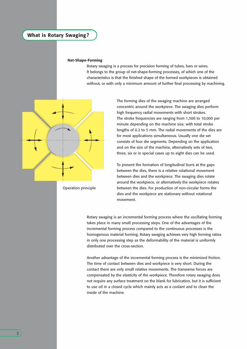
The forming dies of the swaging machine are arranged
concentric around the workpiece. The swaging dies perform
high frequency radial movements with short strokes.
The stroke frequencies are ranging from 1,500 to 10,000 per
minute depending on the machine size, with total stroke
lengths of 0.2 to 5 mm. The radial movements of the dies are
for most applications simultaneous. Usually one die set
consists of four die segments. Depending on the application
and on the size of the machine, alternatively sets of two,
three, six or in special cases up to eight dies can be used.
To prevent the formation of longitudinal burrs at the gaps
between the dies, there is a relative rotational movement
between dies and the workpiece. The swaging dies rotate
around the workpiece, or alternatively the workpiece rotates
between the dies. For production of non-circular forms the
dies and the workpiece are stationary without rotational
movement.
Rotary swaging is an incremental forming process where the oscillating forming
takes place in many small processing steps. One of the advantages of the
incremental forming process compared to the continuous processes is the
homogenous material forming. Rotary swaging achieves very high forming ratios
in only one processing step as the deformability of the material is uniformly
distributed over the cross-section.
Another advantage of the incremental forming process is the minimized friction.
The time of contact between dies and workpiece is very short. During the
contact there are only small relative movements. The transverse forces are
compensated by the elasticity of the workpiece. Therefore rotary swaging does
not require any surface treatment on the blank for lubrication, but it is sufficient
to use oil in a closed cycle which mainly acts as a coolant and to clean the
inside of the machine.
Operation principle
2
Net-Shape-Forming
Net-shape production:
The achievable tolerances are extremely tight so that final machining is in most
cases not required. This enables significant material savings and reduces the
number of production stages, resulting in low piece prices.
Wide range of applications, significant weight savings:
Rotary swaging can produce a multitude of different external and internal
forms. Weight savings of up to 30% - 50% can generally be achieved by rotary
swaging versus conventional production methods.
High product quality:
The uninterrupted grain flow of the material together with the work-hardening
resulting from the reduction increase the strength of the workpiece. The quality
of swaged surfaces is at the level of ground surfaces.
High forming ratios, no restriction to materials:
Rotary swaging achieves high forming ratios without requiring hot forming.
The favorable distribution of stresses during forming and the homogenous
course of processing permit to form also brittle materials.
Cold and hot forming:
Rotary swaging forms materials in the cold, semi-hot and hot temperature
range.
Environmental acceptability:
Unlike other forming processes, rotary swaging does not require any surface
treatment on the blank. The oil, if required, is in a closed cycle.
Versatility:
Rotary swaging machines have short change-over times. The swaging dies and
the machine setting are changed within a few minutes.
Short production times, high efficiency rates:
The construction of rotary swaging machines permits combination of several
processing modules for efficient multi-station transfer lines so that net-shape
parts can be produced with high outputs. The robust and easy to maintain
construction ensures high efficiency rates.
Advantages of Rotary Swaging
3
Examples of Applications
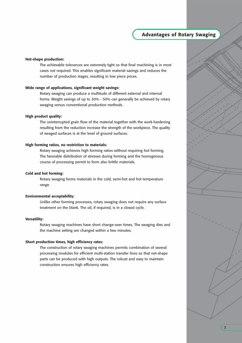
Hollow Steering Column
Steering columns are nowadays commonly produced by rotary swaging worldwide. Starting
from a cylindrical tube blank, the steering tubes are produced an single-station machines or on
multi-station transfer lines with typical cycle times of about 10 to 16 seconds depending on the
workpiece forms and sizes. Transfer lines including modules for the other processes produce
completed net-shape parts.
Hollow Driveshaft:
Rotary swaging produces hollow driveshafts in Monobloc design. By reducing the wall
thickness in the center section of the shaft it is possible to obtain a component with optimized
weight. The starting materials are cylindrical tubes, which are processed on single-station
machines or on multi-station transfer lines to net-shape components. The cycle times are
typically about 15 to 20 seconds.
Temples
These parts are traditionally produced by rotary swaging. The process is either used for
production of pre-formed parts for subsequent stamping of prismatic shapes without burrs,
or as a net-shape forming process for production of temples with circular form.
Fittings:
Rotary swaging produces fitting profiles an steel and aluminum tubes with highest quality.
The process can create external forms with sharp corners at the transitions together with a
constant inside diameter. Rotary swaging can be combined with an upsetting process for
production of beads. Depending on the production volumes, the fittings are produced on
single-station machines or on multi-station transfer lines, with cycle times of typically about
12 to 18 seconds.
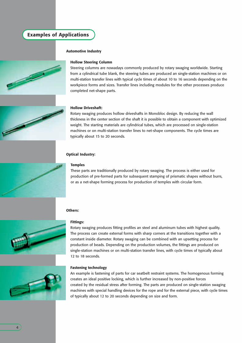
Fastening technology
An example is fastening of parts for car seatbelt restraint systems. The homogenous forming
creates an ideal positive locking, which is further increased by non-positive forces
created by the residual stress after forming. The parts are produced on single-station swaging
machines with special handling devices for the rope and for the external piece, with cycle times
of typically about 12 to 20 seconds depending on size and form.
4
Automotive Industry
Optical Industry:
Others:
Rotary Swaging Machines
5
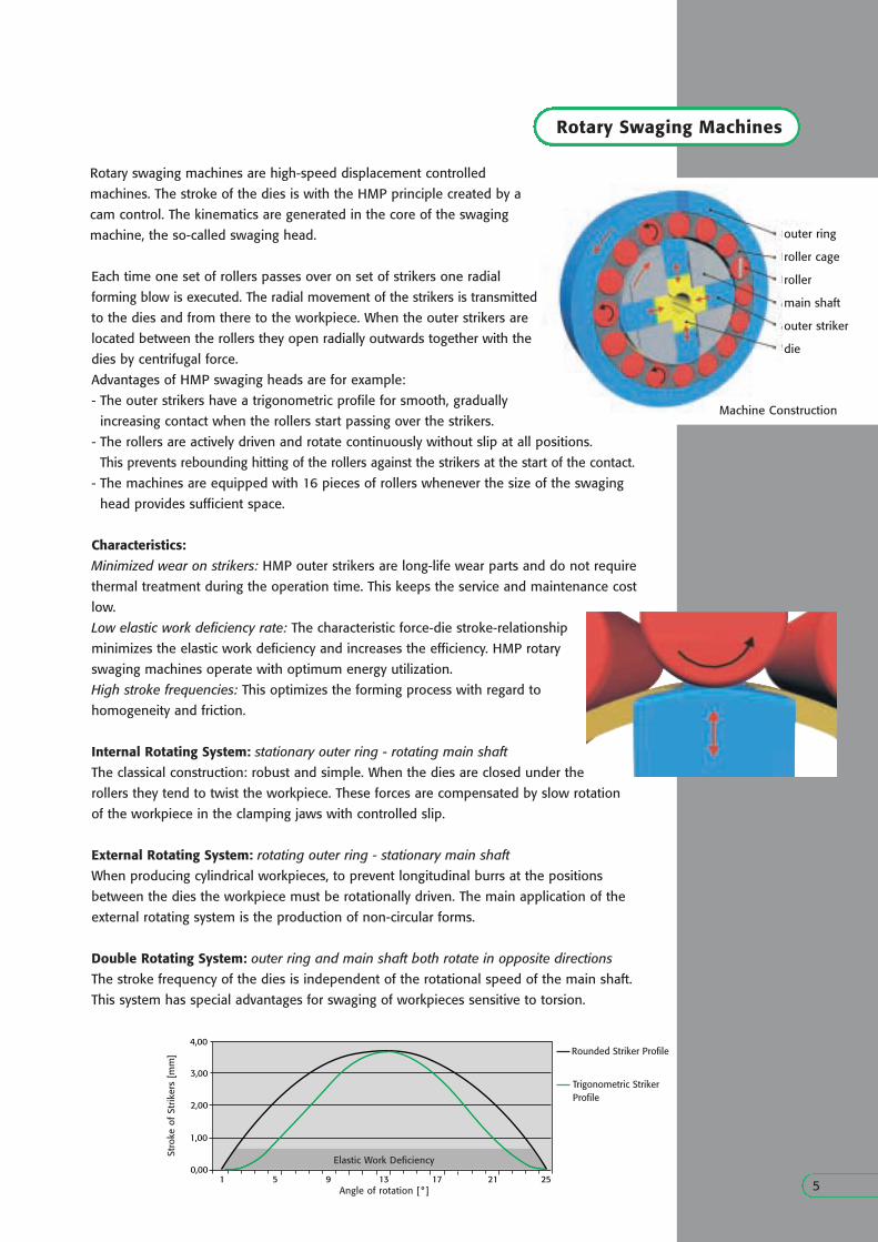
Rotary swaging machines are high-speed displacement controlled
machines. The stroke of the dies is with the HMP principle created by a
cam control. The kinematics are generated in the core of the swaging
machine, the so-called swaging head.
1 5 9 13 17 21 25
4,00
3,00
2,00
1,00
0,00
Angle of rotation [ ° ]
Stro
ke o
f St
rike
rs [
mm
]
Elastic Work Deficiency
Trigonometric StrikerProfile
Machine Construction
outer ring
roller cage
roller
main shaft
outer striker
die
Each time one set of rollers passes over on set of strikers one radial
forming blow is executed. The radial movement of the strikers is transmitted
to the dies and from there to the workpiece. When the outer strikers are
located between the rollers they open radially outwards together with the
dies by centrifugal force.
Advantages of HMP swaging heads are for example:
- The outer strikers have a trigonometric profile for smooth, gradually
increasing contact when the rollers start passing over the strikers.
- The rollers are actively driven and rotate continuously without slip at all positions.
This prevents rebounding hitting of the rollers against the strikers at the start of the contact.
- The machines are equipped with 16 pieces of rollers whenever the size of the swaging
head provides sufficient space.
Characteristics:
Minimized wear on strikers: HMP outer strikers are long-life wear parts and do not require
thermal treatment during the operation time. This keeps the service and maintenance cost
low.
Low elastic work deficiency rate: The characteristic force-die stroke-relationship
minimizes the elastic work deficiency and increases the efficiency. HMP rotary
swaging machines operate with optimum energy utilization.
High stroke frequencies: This optimizes the forming process with regard to
homogeneity and friction.
Internal Rotating System: stationary outer ring - rotating main shaft
The classical construction: robust and simple. When the dies are closed under the
rollers they tend to twist the workpiece. These forces are compensated by slow rotation
of the workpiece in the clamping jaws with controlled slip.
External Rotating System: rotating outer ring - stationary main shaft
When producing cylindrical workpieces, to prevent longitudinal burrs at the positions
between the dies the workpiece must be rotationally driven. The main application of the
external rotating system is the production of non-circular forms.
Double Rotating System: outer ring and main shaft both rotate in opposite directions
The stroke frequency of the dies is independent of the rotational speed of the main shaft.
This system has special advantages for swaging of workpieces sensitive to torsion.
Rounded Striker Profile
The Methods ...
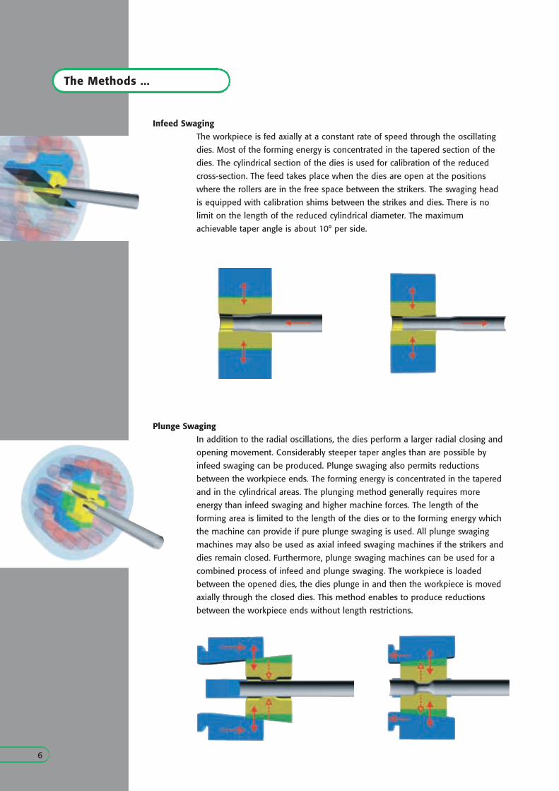
Infeed Swaging
Plunge Swaging
The workpiece is fed axially at a constant rate of speed through the oscillating
dies. Most of the forming energy is concentrated in the tapered section of the
dies. The cylindrical section of the dies is used for calibration of the reduced
cross-section. The feed takes place when the dies are open at the positions
where the rollers are in the free space between the strikers. The swaging head
is equipped with calibration shims between the strikes and dies. There is no
limit on the length of the reduced cylindrical diameter. The maximum
achievable taper angle is about 10° per side.
In addition to the radial oscillations, the dies perform a larger radial closing and
opening movement. Considerably steeper taper angles than are possible by
infeed swaging can be produced. Plunge swaging also permits reductions
between the workpiece ends. The forming energy is concentrated in the tapered
and in the cylindrical areas. The plunging method generally requires more
energy than infeed swaging and higher machine forces. The length of the
forming area is limited to the length of the dies or to the forming energy which
the machine can provide if pure plunge swaging is used. All plunge swaging
machines may also be used as axial infeed swaging machines if the strikers and
dies remain closed. Furthermore, plunge swaging machines can be used for a
combined process of infeed and plunge swaging. The workpiece is loaded
between the opened dies, the dies plunge in and then the workpiece is moved
axially through the closed dies. This method enables to produce reductions
between the workpiece ends without length restrictions.
6
... of Rotary Swaging
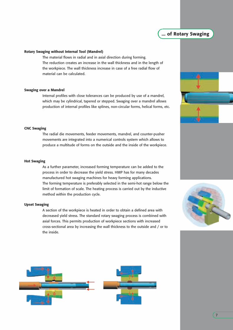
Rotary Swaging without Internal Tool (Mandrel)
The material flows in radial and in axial direction during forming.
The reduction creates an increase in the wall thickness and in the length of
the workpiece. The wall thickness increase in case of a free radial flow of
material can be calculated.
A section of the workpiece is heated in order to obtain a defined area with
decreased yield stress. The standard rotary swaging process is combined with
axial forces. This permits production of workpiece sections with increased
cross-sectional area by increasing the wall thickness to the outside and / or to
the inside.
Swaging over a Mandrel
Upset Swaging
Internal profiles with close tolerances can be produced by use of a mandrel,
which may be cylindrical, tapered or stepped. Swaging over a mandrel allows
production of internal profiles like splines, non-circular forms, helical forms, etc.
7
CNC Swaging
The radial die movements, feeder movements, mandrel, and counter-pusher
movements are integrated into a numerical controls system which allows to
produce a multitude of forms on the outside and the inside of the workpiece.
Hot Swaging
As a further parameter, increased forming temperature can be added to the
process in order to decrease the yield stress. HMP has for many decades
manufactured hot swaging machines for heavy forming applications.
The forming temperature is preferably selected in the semi-hot range below the
limit of formation of scale. The heating process is carried out by the inductive
method within the production cycle.
Workpiece Forms
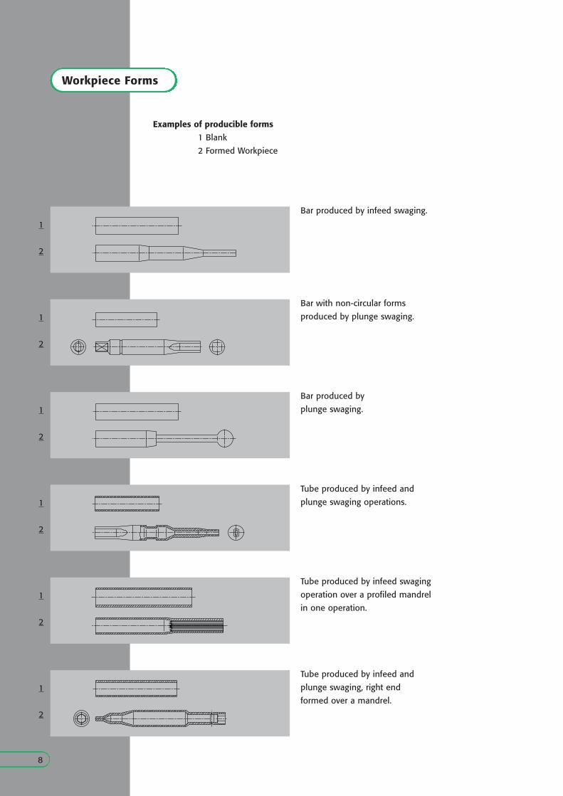
1 Blank
2 Formed Workpiece
Examples of producible forms
Bar produced by infeed swaging.
8
Bar with non-circular forms
produced by plunge swaging.
Bar produced by
plunge swaging.
Tube produced by infeed and
plunge swaging operations.
Tube produced by infeed swaging
operation over a profiled mandrel
in one operation.
Tube produced by infeed and
plunge swaging, right end
formed over a mandrel.
1
2
1
2
1
2
1
2
1
2
1
2
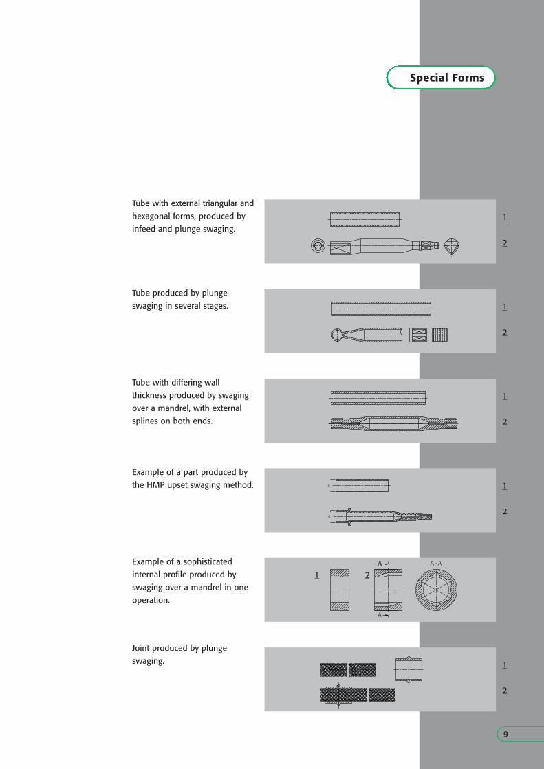
Special Forms
9
Tube with external triangular and
hexagonal forms, produced by
infeed and plunge swaging.
Tube produced by plunge
swaging in several stages.
Tube with differing wall
thickness produced by swaging
over a mandrel, with external
splines on both ends.
Example of a part produced by
the HMP upset swaging method.
Example of a sophisticated
internal profile produced by
swaging over a mandrel in one
operation.
Joint produced by plunge
swaging.
1
2
1
2
1
2
1
2
1 2
1
2
A
A
A - A
-frame
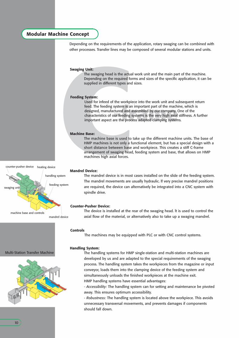
Modular Machine Concept
Depending on the requirements of the application, rotary swaging can be combined with
other processes. Transfer lines may be composed of several modular stations and units.
10
Mandrel Device:
Counter-Pusher Device:The device is installed at the rear of the swaging head. lt is used to control the
axial flow of the material, or alternatively also to take up a swaging mandrel.
Controls The machines may be equipped with PLC or with CNC control systems.
Handling System:The handling systems for HMP single-station and multi-station machines are
developed by us and are adapted to the special requirements of the swaging
process. The handling system takes the workpieces from the magazine or input
conveyor, loads them into the clamping device of the feeding system and
simultaneously unloads the finished workpieces at the machine exit.
HMP handling systems have essential advantages:
- Accessibility: The handling system can for setting and maintenance be pivoted
away. This ensures optimum accessibility.
- Robustness: The handling system is located above the workpiece. This avoids
unnecessary transversal movements, and prevents damages if components
should fall down.
feeding system
machine base and controls
handling system
swaging unit
counter-pusher device
mandrel device
heating device
Multi-Station Transfer Machine
The mandrel device is in most cases installed on the slide of the feeding system.
The mandrel movements are usually hydraulic. lf very precise mandrel positions
are required, the device can alternatively be integrated into a CNC system with
spindle drive.
CSwaging Unit:
The swaging head is the actual work unit and the main part of the machine.Depending on the required forms and sizes of the specific application, it can besupplied in different types and sizes.
Feeding System:Used for infeed of the workpiece into the work unit and subsequent return feed. The feeding system is an important part of the machine, which is designed, manufactured and assembled by our company. One of the characteristics of our feeding systems is the very high axial stiffness. A furtherimportant aspect are the process adapted clamping systems.
Machine Base:The machine base is used to take up the different machine units. The base ofHMP machines is not only a functional element, but has a special design with ashort distance between base and workpiece. This creates a stiff C-framearrangement of swaging head, feeding system and base, that allows on HMPmachines high axial forces.
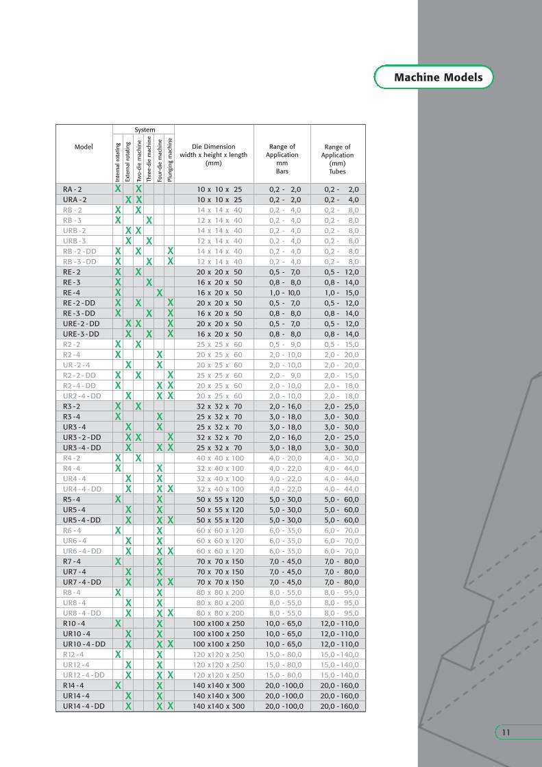
Machine Models
11
Die Dimensionwidth x height x length
(mm)
Range ofApplication
mmBars
RA - 2 10 x 10 x 25 0,2 - 2,0 0,2 - 2,0URA -2 10 x 10 x 25 0,2 - 2,0 0,2 - 4,0RB - 2 14 x 14 x 40 0,2 - 4,0 0,2 - 8,0RB -3 12 x 14 x 40 0,2 - 4,0 0,2 - 8,0URB -2 14 x 14 x 40 0,2 - 4,0 0,2 - 8,0URB -3 12 x 14 x 40 0,2 - 4,0 0,2 - 8,0RB -2 -DD 14 x 14 x 40 0,2 - 4,0 0,2 - 8,0RB -3 -DD 12 x 14 x 40 0,2 - 4,0 0,2 - 8,0RE- 2 20 x 20 x 50 0,5 - 7,0 0,5 - 12,0RE -3 16 x 20 x 50 0,8 - 8,0 0,8 - 14,0RE -4 16 x 20 x 50 1,0 - 10,0 1,0 - 15,0RE -2 -DD 20 x 20 x 50 0,5 - 7,0 0,5 - 12,0RE -3 -DD 16 x 20 x 50 0,8 - 8,0 0,8 - 14,0URE-2 -DD 20 x 20 x 50 0,5 - 7,0 0,5 - 12,0URE-3 -DD 16 x 20 x 50 0,8 - 8,0 0,8 - 14,0R2 -2 25 x 25 x 60 0,5 - 9,0 0,5 - 15,0R2 -4 20 x 25 x 60 2,0 - 10,0 2,0 - 20,0UR -2 -4 20 x 25 x 60 2,0 - 10,0 2,0 - 20,0R2 -2 - DD 25 x 25 x 60 2,0 - 9,0 2,0 - 15,0R2 -4 - DD 20 x 25 x 60 2,0 - 10,0 2,0 - 18,0UR2 -4 - DD 20 x 25 x 60 2,0 - 10,0 2,0 - 18,0R3 -2 32 x 32 x 70 2,0 - 16,0 2,0 - 25,0R3 -4 25 x 32 x 70 3,0 - 18,0 3,0 - 30,0UR3 -4 25 x 32 x 70 3,0 - 18,0 3,0 - 30,0UR3 -2 -DD 32 x 32 x 70 2,0 - 16,0 2,0 - 25,0UR3 -4 - DD 25 x 32 x 70 3,0 - 18,0 3,0 - 30,0R4 -2 40 x 40 x 100 4,0 - 20,0 4,0 - 30,0R4 -4 32 x 40 x 100 4,0 - 22,0 4,0 - 44,0UR4 -4 32 x 40 x 100 4,0 - 22,0 4,0 - 44,0UR4 -4 - DD 32 x 40 x 100 4,0 - 22,0 4,0 - 44,0R5-4 50 x 55 x 120 5,0 - 30,0 5,0 - 60,0UR5-4 50 x 55 x 120 5,0 - 30,0 5,0 - 60,0UR5-4 -DD 50 x 55 x 120 5,0 - 30,0 5,0 - 60,0R6 -4 60 x 60 x 120 6,0 - 35,0 6,0 - 70,0UR6 -4 60 x 60 x 120 6,0 - 35,0 6,0 - 70,0UR6 -4 -DD 60 x 60 x 120 6,0 - 35,0 6,0 - 70,0R7 -4 70 x 70 x 150 7,0 - 45,0 7,0 - 80,0UR7 -4 70 x 70 x 150 7,0 - 45,0 7,0 - 80,0UR7 -4 -DD 70 x 70 x 150 7,0 - 45,0 7,0 - 80,0R8 -4 80 x 80 x 200 8,0 - 55,0 8,0 - 95,0UR8 -4 80 x 80 x 200 8,0 - 55,0 8,0 - 95,0UR8 -4 -DD 80 x 80 x 200 8,0 - 55,0 8,0 - 95,0R10 -4 100 x100 x 250 10,0 - 65,0 12,0 - 110,0UR10 -4 100 x100 x 250 10,0 - 65,0 12,0 - 110,0UR10 -4 -DD 100 x100 x 250 10,0 - 65,0 12,0 - 110,0R12 -4 120 x120 x 250 15,0 - 80,0 15,0 -140,0UR12 -4 120 x120 x 250 15,0 - 80,0 15,0 -140,0UR12 -4 -DD 120 x120 x 250 15,0 - 80,0 15,0 -140,0R14 -4 140 x140 x 300 20,0 -100,0 20,0 -160,0UR14 -4 140 x140 x 300 20,0 -100,0 20,0 -160,0UR14 -4 -DD 140 x140 x 300 20,0 -100,0 20,0 -160,0
xx
xx
xx
x
x
xxx
xxxxxxxxxxxxxxxx
xxxxx
x
xx
x
x
xx
xx
xxxxxxx
xxxxxx
xx
x
x
x
x
x
x
x
xxxx
x
xxxxxxxxxxxxxxxxxxxxxxxxxxxxxxx
xx
xx
xxxx
xxx
xx
x
x
x
x
x
x
x
x
Range ofApplication
(mm)Tubes
Model
Four
-die
mac
hine
Plun
ging
mac
hine
Thre
e-di
e m
achi
ne
Two-
die
mac
hine
System
x
Inte
rnal
rot
atin
g
Exte
rnal
rot
atin
g
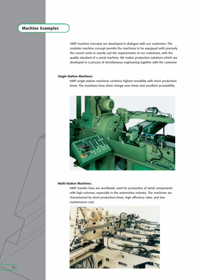
Machine Examples
12
HMP machine concepts are developed in dialogue with our customers. The
modular machine concept permits the machines to be equipped with precisely
the correct units to exactly suit the requirements of our customers, with the
quality standard of a serial machine. We realize production solutions which are
developed in a process of simultaneous engineering together with the customer.
Single-Station Machines:
HMP single-station machines combine highest versatility with short production
times. The machines have short change-over times and excellent accessibility.
Multi-Station Machines:
HMP transfer lines are worldwide used for production of serial components
with high volumes, especially in the automotive industry. The machines are
characterized by short production times, high efficiency rates, and low
maintenance cost.
Economic Efficiency
13
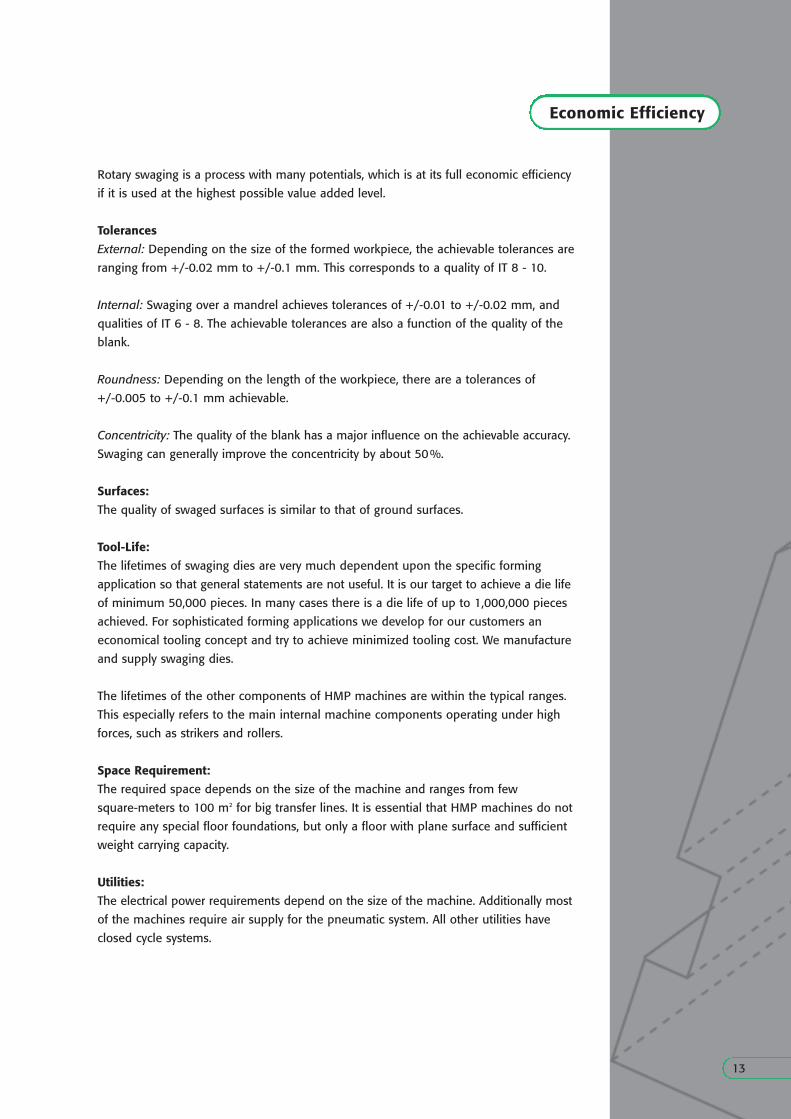
Rotary swaging is a process with many potentials, which is at its full economic efficiency
if it is used at the highest possible value added level.
Tolerances
External: Depending on the size of the formed workpiece, the achievable tolerances are
ranging from +/-0.02 mm to +/-0.1 mm. This corresponds to a quality of IT 8 - 10.
Internal: Swaging over a mandrel achieves tolerances of +/-0.01 to +/-0.02 mm, and
qualities of IT 6 - 8. The achievable tolerances are also a function of the quality of the
blank.
Roundness: Depending on the length of the workpiece, there are a tolerances of
+/-0.005 to +/-0.1 mm achievable.
Concentricity: The quality of the blank has a major influence on the achievable accuracy.
Swaging can generally improve the concentricity by about 50%.
Surfaces:
The quality of swaged surfaces is similar to that of ground surfaces.
Tool-Life:
The lifetimes of swaging dies are very much dependent upon the specific forming
application so that general statements are not useful. It is our target to achieve a die life
of minimum 50,000 pieces. In many cases there is a die life of up to 1,000,000 pieces
achieved. For sophisticated forming applications we develop for our customers an
economical tooling concept and try to achieve minimized tooling cost. We manufacture
and supply swaging dies.
The lifetimes of the other components of HMP machines are within the typical ranges.
This especially refers to the main internal machine components operating under high
forces, such as strikers and rollers.
Space Requirement:
The required space depends on the size of the machine and ranges from few
square-meters to 100 m2 for big transfer lines. It is essential that HMP machines do not
require any special floor foundations, but only a floor with plane surface and sufficient
weight carrying capacity.
Utilities:
The electrical power requirements depend on the size of the machine. Additionally most
of the machines require air supply for the pneumatic system. All other utilities have
closed cycle systems.
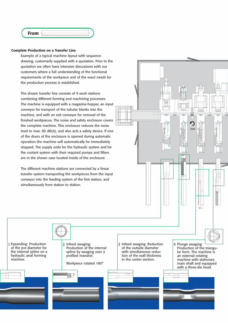
Complete Production on a Transfer Line
Expanding: Productionof the pre-diameter forthe internal spline on ahydraulic axial formingmachine.
Infeed swaging:Production of the internalspline by swaging over aprofiled mandrel.
Workpiece rotated 180°
Infeed swaging: Reductionof the outside diameterwith simultaneous reduc-tion of the wall thicknessin the center section.
Plunge swaging:Production of the triangu-lar form. The machine isan external rotatingmachine with stationarymain shaft and equippedwith a three-die head.
Example of a typical machine layout with sequence
drawing, customarily supplied with a quotation. Prior to the
quotation we often have intensive discussions with our
customers where a full understanding of the functional
requirements of the workpiece and of the exact needs for
the production process is established.
The shown transfer line consists of 9 work stations
combining different forming and machining processes.
The machine is equipped with a magazine-hopper, an input
conveyor for transport of the tubular blanks into the
machine, and with an exit conveyor for removal of the
finished workpieces. The noise and safety enclosure covers
the complete machine. This enclosure reduces the noise
level to max. 80 dB(A), and also acts a safety device. lf one
of the doors of the enclosure is opened during automatic
operation the machine will automatically be immediately
stopped. The supply units for the hydraulic system and for
the coolant system with their required pumps and filters
are in the shown case located inside of the enclosure.
The different machine stations are connected by a linear
transfer system transporting the workpieces from the input
conveyor into the feeding system of the first station, and
simultaneously from station to station.
From
1 2 3 4
turn
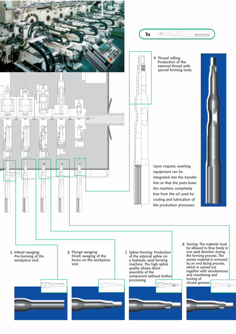
Infeed swaging:Pre-forming of theworkpiece end.
Plunge swaging: Finish swaging of theforms on the workpieceend.
Spline forming: Productionof the external spline on a hydraulic axial formingmachine. The high splinequality allows directassembly of thecomponent without furtherprocessing.
Upon request, washing
equipment can be
integrated into the transfer
line so that the parts leave
the machine completely
free from the oil used for
cooling and lubrication of
the production processes.
Thread rolling:Production of theexternal thread withspecial forming tools.
To
5 6 7
8
9
Turning: The material mustbe allowed to flow freely inone axial direction duringthe forming process. Theexcess material is removedby an end facing process,which is carried out together with simultaneousend chamfering and turning of circular grooves.
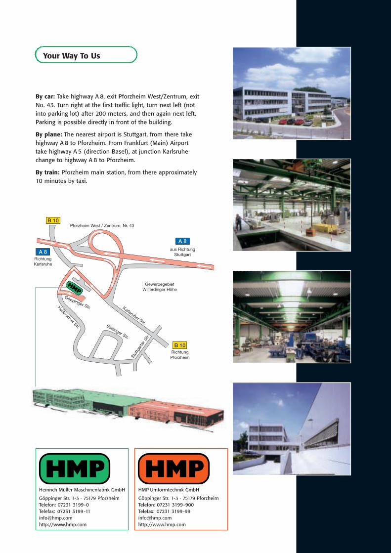
Your Way To Us
By car: Take highway A 8, exit Pforzheim West/Zentrum, exitNo. 43. Turn right at the first traffic light, turn next left (notinto parking lot) after 200 meters, and then again next left.Parking is possible directly in front of the building.
By plane: The nearest airport is Stuttgart, from there takehighway A 8 to Pforzheim. From Frankfurt (Main) Airporttake highway A 5 (direction Basel), at junction Karlsruhechange to highway A 8 to Pforzheim.
By train: Pforzheim main station, from there approximately 10 minutes by taxi.
Heinrich Müller Maschinenfabrik GmbH
Göppinger Str. 1-3 · 75179 PforzheimTelefon: 07231 3199-0 Telefax: 07231 [email protected] http://www.hmp.com
HMP Umformtechnik GmbH
Göppinger Str. 1-3 · 75179 PforzheimTelefon: 07231 3199-900 Telefax: 07231 [email protected] http://www.hmp.com
A 8
aus RichtungStuttgart
RichtungKarlsruhe
Karlsruher Str.Esslinger Str.
Stut
tgar
ter S
tr.
Heilbronner Str.
Göppinger Str.
RichtungPforzheim
Pforzheim West / Zentrum, Nr. 43
GewerbegebietWilferdinger Höhe
A 8
B 10
B 10


