36
ENGINEERING CATALOG MT123 US ROTATING UNIONS For Machine Tools, Machining Centers and Transfer Lines www.deublin.com

ENGINEERING CATALOG
MT123 US
ROTATING UNIONSFor Machine Tools, Machining Centers and Transfer Lines
w w w . d e u b l i n . c o m

1154 series (p. 26)
1129 series (p. 25)
+ 1 - 8 4 7 - 6 8 9 - 8 6 0 0 o r w w w . d e u b l i n . c o m2
1 Does the machine have a single supply connection (for example, coolant) or multiple connections (such as a combination of coolant, air, and hydraulic oil)?
2 What fluid or fluids must be transferred by the rotating union?
3 What is the maximum pressure required?
4 What is the maximum spindle speed required?
4 STEPS TO FINDING THE CORRECT UNION SERIES FOR YOUR MACHINE TOOL APPLICATION
1 Number of Inputs
2 Fluid(s) to Transfer
4 Maximum Speed (rpm)
up to 10K up to 15K up to 20K up to 36K over 36K
Single
Coolant or MQL (always present during
rotation)
Air + Coolant/MQL (rotation with air pressure
is possible)
1116 series (p.11)
902 series (p.15) 1109 series (p.16, 17)
1117 series (p. 21), Multi-spindle unions (p. 22)
1115 series (p. 20)
1121, 1129 and 1151 series (p. 23-25)
1005 series (p.14)
Air only
Hydraulic Oil
Hydraulic Oil + Hydraulic Oil
Hydraulic Oil + Air
Coolant or MQL + Air
Coolant + Hydraulic Oil(with no interpassage
leakage)
Air + Air
Multiple
Bearing-supported (one-piece) unions Bearingless (two-piece) unions
3 Maximum Pressure
Coolant or MQL (rotation with no coolant
is possible)
up to 70 bar
up to 140 bar
up to 70 bar
up to 140 bar
up to 140 bar
up to 70 bar
up to 10 bar
up to 100 bar
up to 140 bar
up to 70 bar
up to 140 bar
up to 140 bar
up to 70 bar
up to 140 bar
up to 10 bar
Coolant + Oil + Air up to 140 bar
1101 series (p.12) 1108 series (p.13)
1114 series (p.18, 19)
Contact DEUBLIN
Contact DEUBLIN
Contact DEUBLIN
1139 series (p. 27)
2620-00x-xxx (p. 28)
2620-5xx-xxx(p.28)
2630, 2640, 2650 series (p.30)
Air + Oilup to 60 bar
< 250 rpm1379 & 1479 series (p.31)
2620-24x-xxx2620-26x-xxx (p.29)
2620-14x-xxx2620-16x-xxx (p. 29)
2620-04x-xxx (p. 29)
2620-30x-xxx
2620-32x-xxx
2620-10x-xxx
2620-12x-xxx (p. 28)
2620-40x-xxx
2620-42x-xxx
2620-20x-xxx
2620-22x-xxx (p. 28)
2620-44x-xxx
2620-46x-xxx (p.29)
2620-34x-xxx
2620-36x-xxx (p. 29)
Multi-passage unions
2630-1xx-xxx (p. 30)
DEUBLIN3+ 1 - 8 4 7 - 6 8 9 - 8 6 0 0 o r w w w . d e u b l i n . c o m
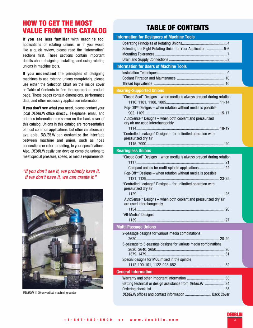
TABLE OF CONTENTSHOW TO GET THE MOST VALUE FROM THIS CATALOG
DEUBLIN
If you are less familiar with machine tool applications of rotating unions, or if you would like a quick review, please read the “Information” sections first. These sections contain important details about designing, installing, and using rotating unions in machine tools.
If you understand the principles of designing machines to use rotating unions completely, please use either the Selection Chart on the inside cover or Table of Contents to find the appropriate product page. These pages contain dimensions, performance data, and other necessary application information.
If you don’t see what you need, please contact your local DEUBLIN office directly. Telephone, email, and address information are shown on the back cover of this catalog. Unions in this catalog are representative of most common applications, but other variations are available. DEUBLIN can customize the interface between machine and union, such as hose connections or rotor threading, to your specifications. Also, DEUBLIN easily can develop complete unions to meet special pressure, speed, or media requirements.
Information for Designers of Machine ToolsOperating Principles of Rotating Unions............................................. 4Selecting the Right Rotating Union for Your Application .................5-6Mounting Tolerances ........................................................................ 7Drain and Supply Connections .......................................................... 8
Information for Users of Machine ToolsInstallation Techniques .................................................................... 9Coolant Filtration and Maintenance ............................................... 10Thread Equivalence ...................................................................... 10
Bearing-Supported Unions“Closed Seal” Designs – when media is always present during rotation 1116, 1101, 1108, 1005..................................................... 11-14 Pop-OffTM Designs – when rotation without media is possible
902, 1109........................................................................... 15-17 AutoSenseTM Designs – when both coolant and pressurized dry air are used interchangeably
1114................................................................................... 18-19“ Controlled Leakage” Designs – for unlimited operation with pressurized dry air
1115, 7000.............................................................................. 20
Bearingless Unions“Closed Seal” Designs – when media is always present during rotation
1117........................................................................................ 21 Compact unions for multi-spindle applications ......................... 22 Pop-OffTM Designs – when rotation without media is possible
1121, 1129......................................................................... 23-25“ Controlled Leakage” Designs – for unlimited operation with pressurized dry air
1129........................................................................................ 25 AutoSenseTM Designs – when both coolant and pressurized dry air are used interchangeably
1154........................................................................................ 26“All-Media” Designs
1139........................................................................................ 27
Multi-Passage Unions2-passage designs for various media combinations
2620................................................................................... 28-293-passage to 5-passage designs for various media combinations
2630, 2640, 2650.................................................................... 30 1379, 1479.............................................................................. 31
Special designs for MQL mixed in the spindle1112-100-101, 1122-923-852 ................................................ 32
General InformationWarranty and other important information ..................................... 33Getting technical or design assistance from DEUBLIN ................... 34Ordering check list ......................................................................... 35DEUBLIN offices and contact information .......................... Back Cover
“ If you don’t see it, we probably have it. If we don’t have it, we can create it.”
DEUBLIN 1109 on vertical machining center

INFORMATION FOR DESIGNERS OF MACHINE TOOLS
4 + 1 - 8 4 7 - 6 8 9 - 8 6 0 0 o r w w w . d e u b l i n . c o m
OPERATING PRINCIPLES OF ROTATING UNIONS
Advantage of Through-Spindle Coolant (TSC)Nearly all modern machine tools and machining centers are equipped with so-called “flood coolant”. High-speed cutting tools require both cooling and lubrication to reduce the rate of tool wear and to prevent overheating, which degrade the tool’s strength. Flood coolant systems spray coolant fluid onto the work piece near the cutting tool. But for many machining operations, such as milling or hole drilling, these systems are less effective at getting coolant fluid to the cutting edge.
Without coolant, the flutes of the cutting tool can become packed with chips and the cutting edge loses hardness due to overheating. This leads to excessive wear and short tool life. Poor chip removal also can cause a poor surface finish on the work piece.
In machining centers with through-spindle coolant (TSC), coolant fluid is conducted directly through the cutting tool to cool the cutting edge, reduce friction, and remove chips. Coolant flows axially through a rotating union into the spindle and tool holder directly to the heat source. Compared to flood coolant systems, TSC pays for itself in terms of lower operating costs for tools and coolant. Better control of tool overheating also allows faster feed rates and higher productivity.
How Rotating Unions WorkA rotating union is a precision mechanical device used to transfer coolant fluid or media from a stationary source, such as a pump, into a rotating device, such as a spindle with cutting tool. The typical coolant fluid is water-based, consisting of approximately 85-95% water for cooling, 2-12% oil for lubricating the cutting edge, and a small amount of other chemicals for keeping the water and oil mixed and for other purposes. DEUBLIN Rotating Unions also can transfer air/oil mist, known as Minimum Quantity Lubrication (MQL), cutting oils, and even dry air. The exact capabilities vary by model number, so please consult the product pages of this catalog for details.
In certain machine tool applications, rotating unions also are used to transfer hydraulic fluid or air for clamping or sensing.
As shown in the picture above, a typical rotating union consists of a rotor that spins at the same speed as the machine tool spindle, a non-rotating element that closes precisely against the rotor, a housing that connects the supply hose to the non-rotating element, and seals that contain the coolant fluid. Bearing-supported unions connect the rotor to the housing with one or more bearings. Bearingless unions omit these bearings. Depending on the application, the housing may have one or more drain connections.
Seals are the heart of the rotating union. They must contain very high pressures while rotating at very high speeds. At 20,000 rpm, for example, the seals of a DEUBLIN 1129 series coolant union are moving at a relative speed of nearly 16 feet per second (5 meters per second), while containing 2030 psi (140 bar) of fluid pressure!
For positive sealing, smooth rotation, and long service life, all DEUBLIN seals are micro-lapped with proprietary machines and compounds to achieve an optical flatness of 2 light bands (23 millionths of an inch, or 0.58 microns). In addition, all DEUBLIN coolant unions use seals made from special grades of silicon carbide. DEUBLIN seals therefore have superior resistance to wear and heat accumulation, compared to lesser materials.
Finally, DEUBLIN Rotating Unions are designed with balanced mechanical seals. With this technology, seal contact pressure and thrust load on the spindle are minimized, regardless of operating pressure. This reduces seal wear even further, resulting in longer life and more reliable performance.
Flood Coolant Through-Spindle Coolant
DEUBLIN Balanced Mechanical Seal Partial line pressure is applied to seal face.
SpindleRotor
BearingsHousing Drain
Seals
Non-Rotating Element
Supply Hose
Micro-lapped DEUBLIN seal
Parts of a Rotating Union
DEUBLIN5+ 1 - 8 4 7 - 6 8 9 - 8 6 0 0 o r w w w . d e u b l i n . c o m
INFORMATION FOR DESIGNERS OF MACHINE TOOLS
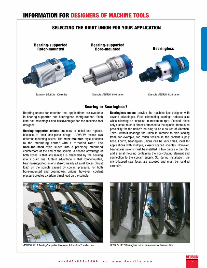
Rotating unions for machine tool applications are available in bearing-supported and bearingless configurations. Each kind has advantages and disadvantages for the machine tool designer.
Bearing-supported unions are easy to install and replace, because of their one-piece design. DEUBLIN makes two different mounting styles. The rotor-mounted style attaches to the machining center with a threaded rotor. The bore-mounted style slides into a precisely machined counterbore at the end of the spindle. A second advantage of both styles is that any leakage is channeled by the housing into a drain line. A third advantage is that rotor-mounted, bearing-supported unions absorb nearly all axial forces (thrust load) on the spindle caused by coolant pressure. For both bore-mounted and bearingless unions, however, coolant pressure creates a certain thrust load on the spindle.
SELECTING THE RIGHT UNION FOR YOUR APPLICATION
Bearingless unions provide the machine tool designer with several advantages. First, eliminating bearings reduces cost while allowing an increase in maximum rpm. Second, since only a small rotor is directly attached to the spindle, there is no possibility for the union’s housing to be a source of vibration. Third, without bearings the union is immune to side loading from, for example, too much tension in the coolant supply hose. Fourth, bearingless unions can be very small, ideal for applications with multiple, closely spaced spindles. However, bearingless unions must be installed in two pieces – the rotor and a small housing containing the non-rotating element and connection to the coolant supply. So, during installation, the micro-lapped seal faces are exposed and must be handled carefully.
Bearing or Bearingless?
Bearing-supported Rotor-mounted
Bearing-supported Bore-mounted Bearingless
Example: DEUBLIN 1109 series Example: DEUBLIN 1109 series Example: DEUBLIN 1129 series
DEUBLIN 1116 Bearing-Supported Unions on Automotive Transfer Line DEUBLIN 1117 Bearingless Unions on Automotive Transfer Line
+ 1 - 8 4 7 - 6 8 9 - 8 6 0 0 o r w w w . d e u b l i n . c o m6
DEUBLIN offers five different seal technologies, in order to provide the best solution for every machining application. Only DEUBLIN can offer such flexibility to the machine tool designer.
Closed Seal: As the name indicates, the seals stay closed with or without coolant pressure. Therefore, drain lines generally are not required. However, all rotating unions operate with a thin film of media between the seals. Over time, small, nearly invisible quantities of media can migrate across the seal faces. Therefore, proper venting provisions should be made. Closed seal unions generally are less affected by extremely contaminated coolant than other designs. However, closed seal unions should not be rotated for an extended time if coolant fluid is not present.
Controlled Leakage: The opposite of closed seals, controlled leakage seals always have a small gap between the seals, even when pressure is applied. For this reason, controlled leakage unions are excellent for high-speed applications with pressurized dry air. Controlled leakage unions generally are not suitable for coolant fluid applications.
Pop-Off TM: This kind of seal closes only when pressure is applied. When pressure is removed, the seal faces separate by a very small distance. This eliminates friction and seal wear during operation without coolant, and therefore allows unlimited “dry running” at high speeds. Pop-OffTM designs should be considered when machining will occur with and without through-spindle
INFORMATION FOR DESIGNERS OF MACHINE TOOLS
SELECTING THE RIGHT UNION FOR YOUR APPLICATION
coolant (TSC). Because the seals separate during tool changes when coolant pressure is off, residual coolant in the supply hose and spindle can drain through the seal faces. Therefore, a Pop-OffTM union generally requires a downward-pointing drain line to direct such residual coolant into the sump. Also note that Pop-OffTM unions are not intended for extended operation with pressurized dry air.
AutoSenseTM: The latest in a series of DEUBLIN innovations, this technology combines the best features of Pop-Off TM and controlled leakage designs. Like Pop-OffTM designs, AutoSenseTM seals close when coolant pressure is applied to contain the coolant fluid, and “pop” apart in the absence of coolant pressure to allow unlimited dry running. Like controlled leakage designs, AutoSenseTM seals handle pressurized dry air by creating a microscopic gap between the seal faces. AutoSenseTM unions handle coolant, MQL, and dry air by sensing the kind of media and automatically changing seal operation in response. As with Pop-OffTM seals, a drain line generally is required.
All-Media: This technology gives the machine designer complete control over seal opening and closing. By controlling how the pressure is applied to the union’s multiple connections, the machine designer can cause the seals to separate when necessary (for example, to transfer pressurized dry air) or close when appropriate (to transfer coolant fluid or oil mist). A drain line generally is required.
Which DEUBLIN® Seal Technology?
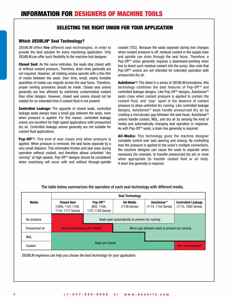
DEUBLIN engineers can help you choose the best technology for your application.
The table below summarizes the operation of each seal technology with different media.
Seals are closed
Seal Technology
Media Closed Seal Pop-Off TM All-Media AutoSenseTM Controlled Leakage (1005, 1101,1108, (902, 1109, (1139 Series) (1114, 1154 Series) (1115, 7000 Series) 1116, 1117 Series) 1121,1129 Series)
No pressure Seals open automatically to prevent dry running
Pressurized air Not recommended with rotation Micro-gap between seals to prevent dry running
MQL
Coolant Not recommended

DEUBLIN7+ 1 - 8 4 7 - 6 8 9 - 8 6 0 0 o r w w w . d e u b l i n . c o m
INFORMATION FOR DESIGNERS OF MACHINE TOOLS
MOUNTING TOLERANCES
The interface between spindle and union must be manufactured to precise tolerance to ensure accurate, vibration-free operation. Bearingless unions and rotor-mounted, bearing-supported unions
XA
1.5 x 30°
Z
Y
AØ0.007
0.005 A
Rz10
Rz10
A
H
M
F
AI
Bore-mounted, bearing-supported unions require one of the following two interfaces:
Spindle End Rotor End Installed Rotor
All dimensions in millimeters unless otherwise indicated.
require the spindle end to be machined according to the following dimensions and tolerances:
Datum A is the axis of rotation
Table shows reference data:Please refer to the dimensions on the individual drawing when dimensioning the spindle.
Rotor Connection Rotor Pilot Spindle End Tightening
A F H I M X Y Z Torque
5/8"-18 UNF 9/16" 15/16" 0.6555” / 0.6553" 3/16" 0.6560” / 0.6556" 9/32" 13/16" 35 Nm
5/8"-18 UNF 9/16" 15/16" 0.6249” / 0.6246" 3/32" 0.6254” / 0.6250" 3/16" 9/16" 35 Nm
M16 x 1.5 11 24 17.993 / 17.988 5 18.000 / 17.995 8.5 17 35 Nm
M16 x 1.5 11 24 16.025 / 16.020 5 16.037 / 16.027 7 17 35 Nm
M14 x 1.5 12 24 14.494 / 14.486 5 14.508 / 14.500 7 18 25 Nm
M12 x 1.25 11 24 13.994 / 13.989 5 14.005 / 14.000 7 17 15 Nm
M12 x 1 / M12 x 1.25 13 15 12.994 / 12.989 6 13.005 / 13.000 9 23 15 Nm
M10 x 1 11 17 10.994 / 10.989 3 11.008 / 11.000 5.2 15 10 Nm
M8 x 1 12.5 15 8.995 / 8.991 3.5 9.006 / 9.000 6 18 4 Nm
Hexagon
Hub
* 2x bracket and 2x screw supplied by customer.
Octagon
Max.Hub
* 2x bracket and 2x screw supplied by customer.
8 + 1 - 8 4 7 - 6 8 9 - 8 6 0 0 o r w w w . d e u b l i n . c o m
INFORMATION FOR DESIGNERS OF MACHINE TOOLS
DRAIN AND SUPPLY HOSE CONNECTIONS
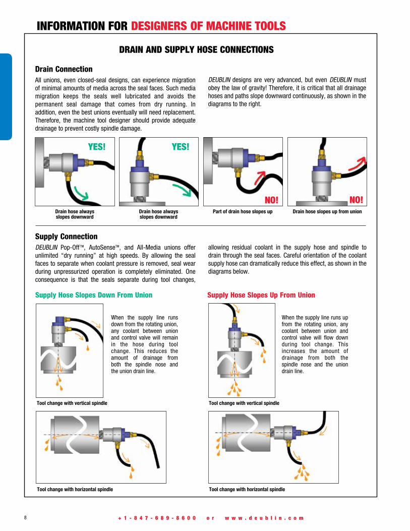
Drain ConnectionAll unions, even closed-seal designs, can experience migration of minimal amounts of media across the seal faces. Such media migration keeps the seals well lubricated and avoids the permanent seal damage that comes from dry running. In addition, even the best unions eventually will need replacement. Therefore, the machine tool designer should provide adequate drainage to prevent costly spindle damage.
Supply ConnectionDEUBLIN Pop-OffTM, AutoSenseTM, and All-Media unions offer unlimited “dry running” at high speeds. By allowing the seal faces to separate when coolant pressure is removed, seal wear during unpressurized operation is completely eliminated. One consequence is that the seals separate during tool changes,
When the supply line runs down from the rotating union, any coolant between union and control valve will remain in the hose during tool change. This reduces the amount of drainage from both the spindle nose and the union drain line.
When the supply line runs up from the rotating union, any coolant between union and control valve will flow down during tool change. This increases the amount of drainage from both the spindle nose and the union drain line.
Drain hose always slopes downward
Part of drain hose slopes upDrain hose always slopes downward
Drain hose slopes up from union
YES! YES!
NO! NO!
Tool change with vertical spindle
Tool change with horizontal spindle Tool change with horizontal spindle
Supply Hose Slopes Down From Union Supply Hose Slopes Up From Union
Tool change with vertical spindle
DEUBLIN designs are very advanced, but even DEUBLIN must obey the law of gravity! Therefore, it is critical that all drainage hoses and paths slope downward continuously, as shown in the diagrams to the right.
allowing residual coolant in the supply hose and spindle to drain through the seal faces. Careful orientation of the coolant supply hose can dramatically reduce this effect, as shown in the diagrams below.

DEUBLIN9+ 1 - 8 4 7 - 6 8 9 - 8 6 0 0 o r w w w . d e u b l i n . c o m
INFORMATION FOR USERS OF MACHINE TOOLS
INSTALLATION TECHNIqUES
Installing a DEUBLIN Rotating Union is as easy as 1-2-3. For maximum life and reliability, maintenance engineers and service technicians need only to follow a few simple rules.
1. For bearing-supported, rotor-mounted unions, connect both supply and drain hoses to the union before mounting the union on the spindle. Otherwise, bearings in the union may become brinnelled or galled when the hose connections are tightened.
2. Clean the mounting surfaces of the spindle thoroughly before mounting the union. The spindle pilot must be clean, with no chips, no burrs, and no dents. Otherwise, the union may exhibit runout and vibrate during rotation.
3. Make sure the drain hose runs downward continuously, with no “roller coaster” rises that could prevent proper drainage. If the spindle is horizontal, make sure that the union’s drain hole is at 6 o’clock, pointing directly down. unions can do many things, but they can’t break the law of gravity!
Following are examples of correct and incorrect installations, with an explanation of what is correct or incorrect about each example.
WHAT’S RIGHT: Flexible hose between rigid supply pipe and union. Drain hose runs straight down.
WHAT’S RIGHT: Flexible hose between rigid supply pipe and union. Drain hose runs straight down.
WHAT’S RIGHT: Elbow prevents excessive side load on bearings when supply hose is pressurized.
WHAT’S RIGHT: Elbow fitting is used to avoid a tight bend in supply hose. Drain hose slopes downward.
Examples of CORRECT Installations
WHAT’S WRONG: Union points up. Coolant contaminants will collect at the bottom and interfere with proper sealing.
WHAT’S WRONG: Union housing is rigidly attached to the spindle. Without 100% perfect alignment, this creates a side load leading to early bearing failure.
WHAT’S WRONG: Bend in supply hose is too tight. When pressurized, the supply hose may create a large side load on the union’s bearings.
WHAT’S WRONG: Drain line points up, which can flood the union’s bearings.
Examples of INCORRECT Installations
NO! NO! NO! NO!
YES! YES! YES!YES!

10 + 1 - 8 4 7 - 6 8 9 - 8 6 0 0 o r w w w . d e u b l i n . c o m
INFORMATION FOR USERS OF MACHINE TOOLS
COOLANT FILTRATION AND MAINTENANCE
THREAD EqUIVALENCE
DEUBLIN unions are designed to handle the various coolant contaminants found in most manufacturing facilities. To ensure long union life and maximum productivity, however, coolant filtration should conform to ISO 4406:1999 Code 17/15/12, SAE 749 Class 5, or NAS 1638 Class 8, with a maximum particle size of 60 microns. For comparison, pumps (both fixed piston and variable volume) such as those used in coolant systems typically require ISO 4406 Code 16/14/11 or better – in other words, half as much contamination as DEUBLIN.
Only pure water should be used to make up for coolant evaporation. Calcium and magnesium salts in most tap water shorten coolant life, by depleting the chemicals in the coolant, by breaking down the water-oil emulsion, and by encouraging bacterial growth. These salts also can cause residue to build up
Parallel or “straight” threads are indicated in this catalog by the symbol “G”. British Standard Parallel threads are known by several other names in different parts of the world. Common symbols for this thread style include: BSP, BSPP, BSSPI, BSPF, BSPG, PF, Rp, and G. British Standard parallel threads also may be referred to as British Gas, British Pipe Parallel or Parallel Fastening Thread. The reference standards are described in ISO 228/1 and JIS B0202.
American Standard Unified threads, indicated by UN or UNF, also are parallel. However, they are not the same as and do not mate with G threads, since the thread angle and shape are different.
Tapered threads are indicated in this catalog by the symbols “PT” and “NPT”. British Standard Taper threads are known by several other names, including: BSPT, BSPTr, PS, PT, R, and Rc. British Standard taper threads also may be referred to as Pipe Taper or Conical Thread. The reference standards are described in ISO 7/1 and JIS B0203.
American Standard NPT threads also are tapered, but not the same as PT threads. Both the thread angle and shape are different, so mating NPT with PT may not create a reliable seal.
The following examples are equivalent parallel threads:
G 1/4" G 1/4" cyl PF 1/4"
R 1/4" Tr 1/4" BSP
The following examples are equivalent tapered threads:
R 1/4" keg G 1/4" co PT 1/4"” R 1/4" Rc 1/4"
1/4" BSPT
Unacceptable (ISO 21/19/17 at 100x)
Acceptable (ISO 16/14/11 at 100x)
inside the rotating union, leading to premature failure. One rule of thumb is that each additional “grain of hardness” (equivalent to 17 ppm or 17 mg/l of calcium carbonate) increases your annual coolant consumption by one percent. Proper coolant maintenance also prolongs tool life and improves the surface finish of your parts.
NAS 1638 Class 8
Particle Particles size (µm) per 100ml
5 – 15 ≤64,000
15 – 25 ≤11,400
25 – 50 ≤2,025
50 – 60 ≤360
SAE 749-1963 Class 5
Particle Particles size (µm) per 100ml
5 – 10 ≤87,000
10 – 25 ≤21,400
25 – 50 ≤3,130
50 – 60 ≤430
ISO 4406:1999 Code 17/15/12
Particle Particles size (µm) per 100ml
4 – 6 ≤130,000
6 – 14 ≤32,000
14 – 60 ≤4,000
DEUBLIN11
T h i s s e r i e s i n c l u d e s a d d i t i o n a l m o d e l s . F o r m o r e i n f o r m a t i o n ,c o n t a c t D E U B L I N a t + 1 - 8 4 7 - 6 8 9 - 8 6 0 0 o r w w w . d e u b l i n . c o m
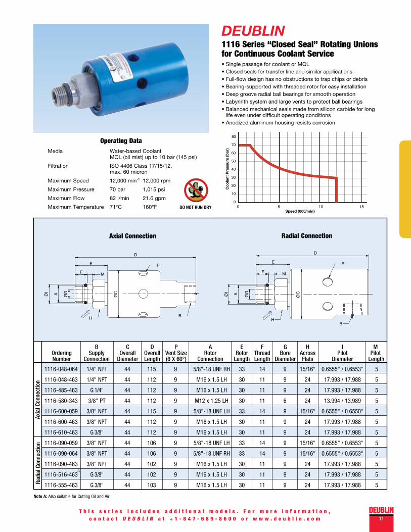
DEUBLIN1116 Series “Closed Seal” Rotating Unions for Continuous Coolant Service• Single passage for coolant or MQL• Closed seals for transfer line and similar applications• Full-flow design has no obstructions to trap chips or debris• Bearing-supported with threaded rotor for easy installation• Deep groove radial ball bearings for smooth operation• Labyrinth system and large vents to protect ball bearings• Balanced mechanical seals made from silicon carbide for long
life even under difficult operating conditions• Anodized aluminum housing resists corrosion
Operating DataMedia Water-based Coolant
MQL (oil mist) up to 10 bar (145 psi)
Filtration ISO 4406 Class 17/15/12, max. 60 micron
Maximum Speed 12,000 min-1 12,000 rpm
Maximum Pressure 70 bar 1,015 psi
Maximum Flow 82 l/min 21.6 gpm
Maximum Temperature 71°C 160°F
Axial Connection Radial Connection
B C D P A E F G H I M Ordering Supply Overall Overall Vent Size Rotor Rotor Thread Bore Across Pilot Pilot Number Connection Diameter Length (6 X 60°) Connection Length Length Diameter Flats Diameter Length
Radi
al C
onne
ctio
nAx
ial C
onne
ctio
nØ
I A ØG
ØC
D
PE
F M
H B
D
P
BH
E
MF
ØI
ØG
ØCA
DO NOT RUN DRY
1116-048-064 1/4" NPT 44 115 9 5/8"-18 UNF RH 33 14 9 15/16" 0.6555" / 0.6553" 5
1116-048-463 1/4" NPT 44 112 9 M16 x 1.5 LH 30 11 9 24 17.993 / 17.988 5
1116-485-463 G 1/4" 44 112 9 M16 x 1.5 LH 30 11 9 24 17.993 / 17.988 5
1116-580-343 3/8" PT 44 112 9 M12 x 1.25 LH 30 11 6 24 13.994 / 13.989 5
1116-600-059 3/8" NPT 44 115 9 5/8"-18 UNF LH 33 14 9 15/16" 0.6555" / 0.6550" 5
1116-600-463 3/8" NPT 44 112 9 M16 x 1.5 LH 30 11 9 24 17.993 / 17.988 5
1116-610-463 G 3/8" 44 112 9 M16 x 1.5 LH 30 11 9 24 17.993 / 17.988 5
1116-090-059 3/8" NPT 44 106 9 5/8"-18 UNF LH 33 14 9 15/16" 0.6555" / 0.6553" 5
1116-090-064 3/8" NPT 44 106 9 5/8"-18 UNF RH 33 14 9 15/16" 0.6555" / 0.6553" 5
1116-090-463 3/8" NPT 44 102 9 M16 x 1.5 LH 30 11 9 24 17.993 / 17.988 5
1116-516-463 G 3/8" 44 102 9 M16 x 1.5 LH 30 11 9 24 17.993 / 17.988 5
1116-555-463 G 3/8" 44 103 9 M16 x 1.5 LH 30 11 9 24 17.993 / 17.988 5
Note A: Also suitable for Cutting Oil and Air.
A
12
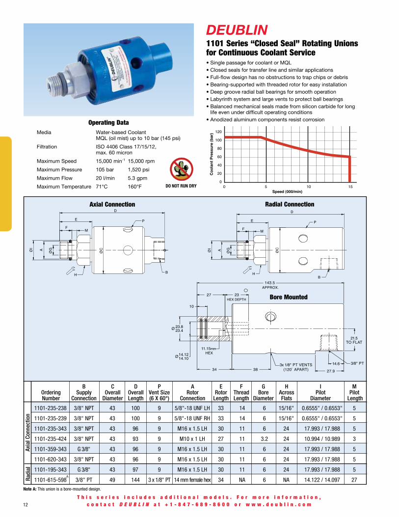
DEUBLIN1101 Series “Closed Seal” Rotating Unions for Continuous Coolant Service• Single passage for coolant or MQL• Closed seals for transfer line and similar applications• Full-flow design has no obstructions to trap chips or debris• Bearing-supported with threaded rotor for easy installation• Deep groove radial ball bearings for smooth operation• Labyrinth system and large vents to protect ball bearings• Balanced mechanical seals made from silicon carbide for long
life even under difficult operating conditions• Anodized aluminum components resist corrosionOperating Data
Media Water-based Coolant MQL (oil mist) up to 10 bar (145 psi)
Filtration ISO 4406 Class 17/15/12, max. 60 micron
Maximum Speed 15,000 min-1 15,000 rpm
Maximum Pressure 105 bar 1,520 psi
Maximum Flow 20 l/min 5.3 gpm
Maximum Temperature 71°C 160°F
Axial Connection
B C D P A E F G H I M Ordering Supply Overall Overall Vent Size Rotor Rotor Thread Bore Across Pilot Pilot Number Connection Diameter Length (6 X 60°) Connection Length Length Diameter Flats Diameter Length
Radi
alAx
ial C
onne
ctio
nØ
I
ØG
ØCA
H B
P
D
E
MF
ØI A Ø
G
ØC
BH
D
PE
F M
T h i s s e r i e s i n c l u d e s a d d i t i o n a l m o d e l s . F o r m o r e i n f o r m a t i o n ,c o n t a c t D E U B L I N a t + 1 - 8 4 7 - 6 8 9 - 8 6 0 0 o r w w w . d e u b l i n . c o m
DO NOT RUN DRY
A
Note A: This union is a bore-mounted design.
1101-235-238 3/8" NPT 43 100 9 5/8"-18 UNF LH 33 14 6 15/16" 0.6555" / 0.6553" 5
1101-235-239 3/8" NPT 43 100 9 5/8"-18 UNF RH 33 14 6 15/16" 0.6555" / 0.6553" 5
1101-235-343 3/8" NPT 43 96 9 M16 x 1.5 LH 30 11 6 24 17.993 / 17.988 5
1101-235-424 3/8" NPT 43 93 9 M10 x 1 LH 27 11 3.2 24 10.994 / 10.989 3
1101-359-343 G 3/8" 43 96 9 M16 x 1.5 LH 30 11 6 24 17.993 / 17.988 5
1101-620-343 3/8" NPT 43 96 9 M16 x 1.5 LH 30 11 6 24 17.993 / 17.988 5
1101-195-343 G 3/8" 43 97 9 M16 x 1.5 LH 30 11 6 24 17.993 / 17.988 5
1101-615-598 3/8" PT 49 144 3 x 1/8" PT 14 mm female hex 34 NA 6 NA 14.122 / 14.097 27
Radial Connection
Bore Mounted

DEUBLIN13
DEUBLIN1108 Series “Closed Seal” Rotating Unions for Continuous Coolant Service• Single passage for coolant or MQL• Closed seals for transfer line and similar applications• Full-flow design has no obstructions to trap chips or debris• Bearing-supported with threaded rotor for easy installation• Dual ABEC 7 (ISO class P4) angular contact ball bearings• Labyrinth system and large vents to protect ball bearings• Balanced mechanical seals made from silicon carbide for long
life even under difficult operating conditions• Anodized aluminum housing resists corrosionOperating Data
Media Water-based Coolant MQL (oil mist) up to 10 bar (145 psi)
Filtration ISO 4406 Class 17/15/12, max. 60 micron
Maximum Speed 20,000 min-1 20,000 rpm
Maximum Pressure See chart
Maximum Flow 82 l/min 21.6 gpm Standard 24.3 l/min 6.4 gpm High Pressure 2.7 l/min 0.7 gpm Very High Pressure (VHP) Maximum Temperature 71°C 160°F
B C D P A E F G H I M Ordering Supply Overall Overall Vent Size Rotor Rotor Thread Bore Across Pilot Pilot Number Connection Diameter Length (3 X 120°) Connection Length Length Diameter Flats Diameter Length
Stan
dard
High
Pre
ssur
eVH
P
Axial Connection Radial Connection
ØI
D
P
B
E
F M
H
A ØG
ØC
T h i s s e r i e s i n c l u d e s a d d i t i o n a l m o d e l s . F o r m o r e i n f o r m a t i o n ,c o n t a c t D E U B L I N a t + 1 - 8 4 7 - 6 8 9 - 8 6 0 0 o r w w w . d e u b l i n . c o m
DO NOT RUN DRY
1108-002-102 3/8" NPT Axial 44 132 9 5/8"-18 UNF LH 34 14 9 15/16" 0.6555" / 0.6553" 5
1108-002-153 3/8" NPT Axial 44 132 9 M16 x 1.5 LH 31 11 9 24 17.993 / 17.988 5
1108-032-153 G 3/8" Axial 44 129 9 M16 x 1.5 LH 31 11 9 24 17.993 / 17.988 5
1108-001-102 3/8" NPT Radial 44 138 9 5/8"-18 UNF LH 34 14 9 15/16" 0.6555" / 0.6553" 5
1108-001-153 3/8" NPT Radial 44 135 9 M16 x 1.5 LH 31 11 9 24 17.993 / 17.988 5
1108-011-153 G 3/8" Radial 44 135 9 M16 x 1.5 LH 30 11 9 24 17.993 / 17.988 5
1108-019-107 1/4" NPT Axial 44 132 9 5/8"-18 UNF LH 34 14 9 15/16" 0.6555" / 0.6553" 5
1108-019-212 1/4" NPT Axial 44 129 9 M16 x 1.5 LH 30 11 9 24 17.993 / 17.988 5
1108-034-212 G 1/4" Axial 53 129 G 1/4" M16 x 1.5 LH 30 11 9 24 17.993 / 17.988 5
1108-058-212 G 1/4" Radial 53 135 G 1/4" M16 x 1.5 LH 30 11 9 24 17.993 / 17.988 5
1108-093-559 1/4" NPT Axial 44 132 9 M16 x 1.5 LH 30 11 9 24 17.993 / 17.988 5
1108-093-568 1/4" NPT Axial 44 132 9 5/8"-18 UNF LH 34 14 9 15/16" 0.6555" / 0.6553" 5

14
DEUBLIN1005 Series “Closed Seal” Rotating Unions for Continuous Coolant Service• Single passage for coolant or MQL• Closed seals for transfer line and similar applications• Full-flow design has no obstructions to trap chips or debris• Bearing-supported with threaded rotor for easy installation• Labyrinth system and vents to protect ball bearings• Balanced mechanical seals made from silicon carbide for long
life even under difficult operating conditions• Anodized housing and stainless steel rotor resist corrosion
Operating Data
Media Water-based Coolant MQL (oil mist) up to 10 bar (145 psi)
Filtration ISO 4406 Class 17/15/12, max. 60 micron
Maximum Speed 15,000 min-1 15,000 rpm
Maximum Pressure 105 bar 1,520 psi
Maximum Flow 6.7 l/min 1.8 gpm
Maximum Temperature 71°C 160°F
Radi
al C
onn.
Other 1005 models are available for use with oil or dry air. Please refer to the DEUBLIN Engineering Catalog 2600.
B
P
D
E
F
M
H
ØI
ØG
ØCA
T h i s s e r i e s i n c l u d e s a d d i t i o n a l m o d e l s . F o r m o r e i n f o r m a t i o n ,c o n t a c t D E U B L I N a t + 1 - 8 4 7 - 6 8 9 - 8 6 0 0 o r w w w . d e u b l i n . c o m
DO NOT RUN DRY
Note A: This union offers limited dry running capability.
1005-402-401 1/8" NPT 34 80 6.4 M10 x 1 RH 22 11 3.2 17 10.994 / 10.989 3
1005-402-448 1/8" NPT 34 80 6.4 M10 x 1 LH 22 11 3.2 17 10.994 / 10.989 3
1005-633-401 1/8" NPT 34 80 1 x M7 M10 x 1 RH 22 11 3.2 17 10.994 / 10.989 3
1005-354-434 1/8" NPT 34 80 6.4 M10 x 1 RH 22 11 3.2 17 10.994 / 10.989 3
B C D P A E F G H I M Ordering Supply Overall Overall Vent Size Rotor Rotor Thread Bore Across Pilot Pilot Number Connection Diameter Length (6 X 60°) Connection Length Length Diameter Flats Diameter Length
A
DEUBLIN15
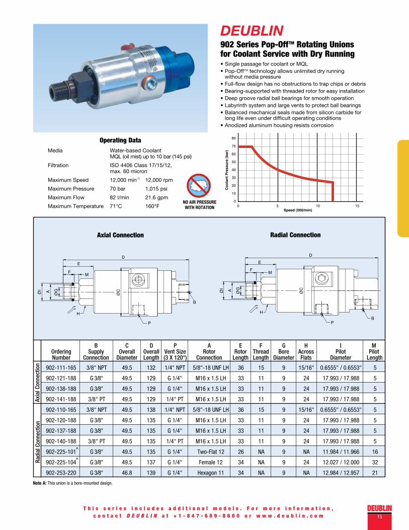
DEUBLIN902 Series Pop-OffTM Rotating Unions for Coolant Service with Dry Running• Single passage for coolant or MQL• Pop-OffTM technology allows unlimited dry running without media pressure• Full-flow design has no obstructions to trap chips or debris• Bearing-supported with threaded rotor for easy installation• Deep groove radial ball bearings for smooth operation• Labyrinth system and large vents to protect ball bearings• Balanced mechanical seals made from silicon carbide for long life even under difficult operating conditions• Anodized aluminum housing resists corrosion
Operating DataMedia Water-based Coolant
MQL (oil mist) up to 10 bar (145 psi)
Filtration ISO 4406 Class 17/15/12, max. 60 micron
Maximum Speed 12,000 min-1 12,000 rpm
Maximum Pressure 70 bar 1,015 psi
Maximum Flow 82 l/min 21.6 gpm
Maximum Temperature 71°C 160°F
Axial Connection Radial Connection
B C D P A E F G H I M Ordering Supply Overall Overall Vent Size Rotor Rotor Thread Bore Across Pilot Pilot Number Connection Diameter Length (3 X 120°) Connection Length Length Diameter Flats Diameter Length
Radi
al C
onne
ctio
nAx
ial C
onne
ctio
n
B
D
P
E
MF
H
ØI A Ø
G
ØC
NO AIR PRESSURE WITH ROTATION
T h i s s e r i e s i n c l u d e s a d d i t i o n a l m o d e l s . F o r m o r e i n f o r m a t i o n ,c o n t a c t D E U B L I N a t + 1 - 8 4 7 - 6 8 9 - 8 6 0 0 o r w w w . d e u b l i n . c o m
902-111-165 3/8" NPT 49.5 132 1/4" NPT 5/8"-18 UNF LH 36 15 9 15/16" 0.6555" / 0.6553" 5
902-121-188 G 3/8" 49.5 129 G 1/4" M16 x 1.5 LH 33 11 9 24 17.993 / 17.988 5
902-138-188 G 3/8" 49.5 129 G 1/4" M16 x 1.5 LH 33 11 9 24 17.993 / 17.988 5
902-141-188 3/8" PT 49.5 129 1/4" PT M16 x 1.5 LH 33 11 9 24 17.993 / 17.988 5
902-110-165 3/8" NPT 49.5 138 1/4" NPT 5/8"-18 UNF LH 36 15 9 15/16" 0.6555" / 0.6553" 5
902-120-188 G 3/8" 49.5 135 G 1/4" M16 x 1.5 LH 33 11 9 24 17.993 / 17.988 5
902-137-188 G 3/8" 49.5 135 G 1/4" M16 x 1.5 LH 33 11 9 24 17.993 / 17.988 5
902-140-188 3/8" PT 49.5 135 1/4" PT M16 x 1.5 LH 33 11 9 24 17.993 / 17.988 5
902-225-101 G 3/8" 49.5 135 G 1/4" Two-Flat 12 26 NA 9 NA 11.984 / 11.966 16
902-225-104 G 3/8" 49.5 137 G 1/4" Female 12 34 NA 9 24 12.027 / 12.000 32
902-253-220 G 3/8" 46.8 139 G 1/4" Hexagon 11 34 NA 9 NA 12.984 / 12.957 21
A
A
Note A: This union is a bore-mounted design.

16
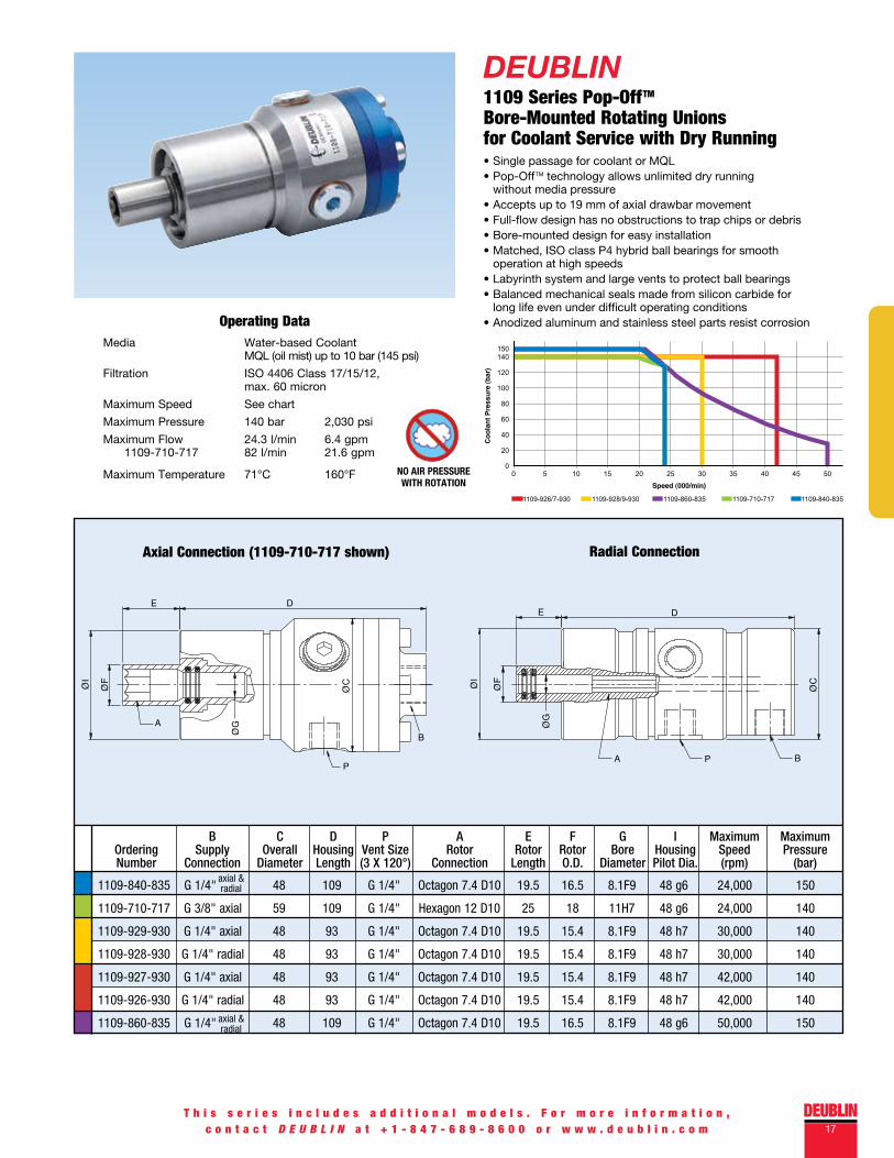
DEUBLIN1109 Series Pop-OffTM Rotor-Mounted Rotating Unions for Coolant Service with Dry Running• Single passage for coolant or MQL• Pop-OffTM technology allows unlimited dry running without media pressure• Full-flow design has no obstructions to trap chips or debris• Bearing-supported with threaded rotor for easy installation• Dual ABEC 7 (ISO class P4) angular contact ball bearings• Labyrinth system and large vents to protect ball bearings• Balanced mechanical seals made from silicon carbide for long life even under difficult operating conditions• Anodized aluminum housing resists corrosion
Operating Data
Axial Connection Radial Connection
B C D P A E F G H I M Ordering Supply Overall Overall Vent Size Rotor Rotor Thread Bore Across Pilot Pilot Number Connection Diameter Length (3 X 120°) Connection Length Length Diameter Flats Diameter Length
High
Pre
ssur
eSt
anda
rd
Media Water-based Coolant MQL (oil mist) up to 10 bar (145 psi)
Filtration ISO 4406 Class 17/15/12, max. 60 micron
Maximum Speed 20,000 min-1 20,000 rpm
Maximum Pressure See chart
Maximum Flow 82 l/min 21.6 gpm Standard 24.3 l/min 6.4 gpm High Pressure
Maximum Temperature 71°C 160°F
B
P
D
M
E
F
H
ØI A ØG
ØC
T h i s s e r i e s i n c l u d e s a d d i t i o n a l m o d e l s . F o r m o r e i n f o r m a t i o n ,c o n t a c t D E U B L I N a t + 1 - 8 4 7 - 6 8 9 - 8 6 0 0 o r w w w . d e u b l i n . c o m
NO AIR PRESSURE WITH ROTATION
1109-011-165 3/8" NPT Axial 53 132 1/4" NPT 5/8"-18 UNF LH 34 14 9 15/16" 0.6555" / 0.6553" 5
1109-021-188 G 3/8" Axial 53 129 G 1/4" M16 x 1.5 LH 31 11 9 24 17.993 / 17.988 5
1109-041-188 3/8" PT Axial 53 129 1/4" PT M16 x 1.5 LH 31 11 9 24 17.993 / 17.988 5
1109-010-165 3/8" NPT Radial 53 138 1/4" NPT 5/8"-18 UNF LH 34 14 9 15/16" 0.6555" / 0.6553" 5
1109-020-188 G 3/8" Radial 53 135 G 1/4" M16 x 1.5 LH 31 11 9 24 17.993 / 17.988 5
1109-040-188 3/8" PT Radial 53 135 1/4" PT M16 x 1.5 LH 31 11 9 24 17.993 / 17.988 5
1109-014-196 1/4" NPT Axial 53 132 1/4" NPT 5/8"-18 UNF LH 34 14 9 15/16" 0.6555" / 0.6553" 5
1109-024-212 G 1/4" Axial 53 129 G 1/4" M16 x 1.5 LH 31 11 9 24 17.993 / 17.988 5
1109-044-212 1/4" PT Axial 53 129 1/4" PT M16 x 1.5 LH 31 11 9 24 17.993 / 17.988 5
1109-013-196 1/4" NPT Radial 53 138 1/4" NPT 5/8"-18 UNF LH 34 14 9 15/16" 0.6555" / 0.6553" 5
1109-023-212 G 1/4" Radial 53 135 G 1/4" M16 x 1.5 LH 31 11 9 24 17.993 / 17.988 5
1109-043-212 1/4" PT Radial 53 135 1/4" PT M16 x 1.5 LH 31 11 9 24 17.993 / 17.988 5
DEUBLIN17
T h i s s e r i e s i n c l u d e s a d d i t i o n a l m o d e l s . F o r m o r e i n f o r m a t i o n ,c o n t a c t D E U B L I N a t + 1 - 8 4 7 - 6 8 9 - 8 6 0 0 o r w w w . d e u b l i n . c o m
DEUBLIN1109 Series Pop-OffTM Bore-Mounted Rotating Unions for Coolant Service with Dry Running• Single passage for coolant or MQL• Pop-OffTM technology allows unlimited dry running without media pressure• Accepts up to 19 mm of axial drawbar movement• Full-flow design has no obstructions to trap chips or debris• Bore-mounted design for easy installation• Matched, ISO class P4 hybrid ball bearings for smooth operation at high speeds• Labyrinth system and large vents to protect ball bearings• Balanced mechanical seals made from silicon carbide for long life even under difficult operating conditions• Anodized aluminum and stainless steel parts resist corrosionOperating Data
Media Water-based Coolant MQL (oil mist) up to 10 bar (145 psi)
Filtration ISO 4406 Class 17/15/12, max. 60 micron
Maximum Speed See chart
Maximum Pressure 140 bar 2,030 psi
Maximum Flow 24.3 l/min 6.4 gpm 1109-710-717 82 l/min 21.6 gpm
Maximum Temperature 71°C 160°F
Axial Connection (1109-710-717 shown) Radial Connection
B
P
DE
A
ØI
ØF
ØG
ØC
NO AIR PRESSURE WITH ROTATION
1109-840-835 G 1/4" 48 109 G 1/4" Octagon 7.4 D10 19.5 16.5 8.1F9 48 g6 24,000 150
1109-710-717 G 3/8" axial 59 109 G 1/4" Hexagon 12 D10 25 18 11H7 48 g6 24,000 140
1109-929-930 G 1/4" axial 48 93 G 1/4" Octagon 7.4 D10 19.5 15.4 8.1F9 48 h7 30,000 140
1109-928-930 G 1/4" radial 48 93 G 1/4" Octagon 7.4 D10 19.5 15.4 8.1F9 48 h7 30,000 140
1109-927-930 G 1/4" axial 48 93 G 1/4" Octagon 7.4 D10 19.5 15.4 8.1F9 48 h7 42,000 140
1109-926-930 G 1/4" radial 48 93 G 1/4" Octagon 7.4 D10 19.5 15.4 8.1F9 48 h7 42,000 140
1109-860-835 G 1/4" 48 109 G 1/4" Octagon 7.4 D10 19.5 16.5 8.1F9 48 g6 50,000 150
B C D P A E F G I Maximum Maximum Ordering Supply Overall Housing Vent Size Rotor Rotor Rotor Bore Housing Speed Pressure Number Connection Diameter Length (3 X 120°) Connection Length O.D. Diameter Pilot Dia. (rpm) (bar)
axial & radial
axial & radial
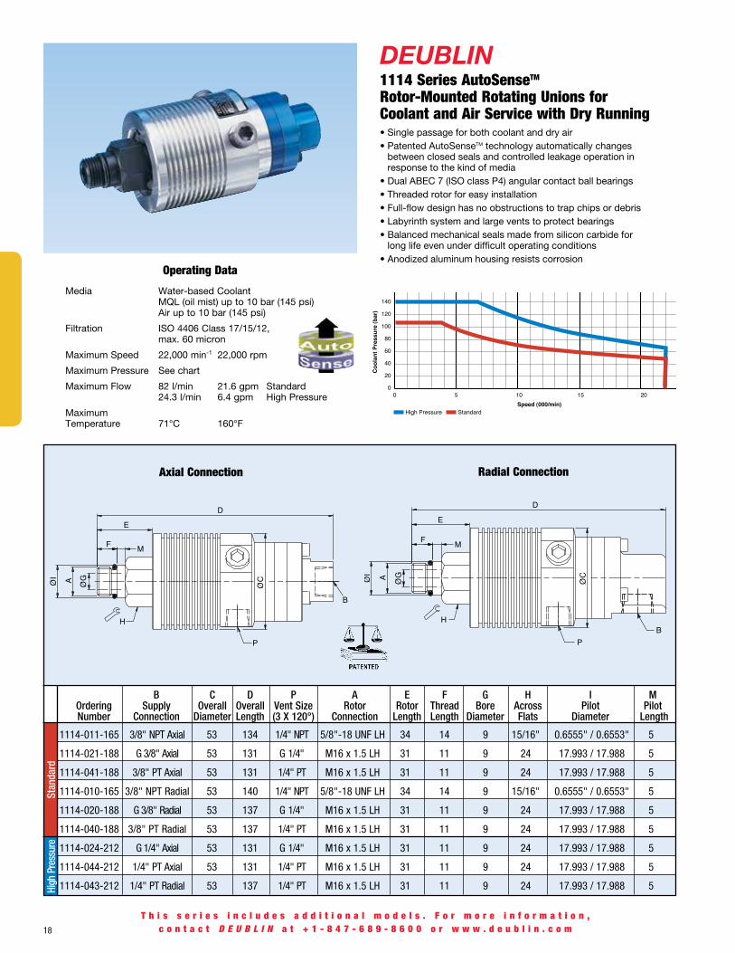
DEUBLIN1114 Series AutoSenseTM Rotor-Mounted Rotating Unions for Coolant and Air Service with Dry Running• Single passage for both coolant and dry air• Patented AutoSenseTM technology automatically changes between closed seals and controlled leakage operation in response to the kind of media• Dual ABEC 7 (ISO class P4) angular contact ball bearings• Threaded rotor for easy installation• Full-flow design has no obstructions to trap chips or debris• Labyrinth system and large vents to protect bearings• Balanced mechanical seals made from silicon carbide for long life even under difficult operating conditions• Anodized aluminum housing resists corrosion
Operating Data
Axial Connection Radial Connection
B C D P A E F G H I M Ordering Supply Overall Overall Vent Size Rotor Rotor Thread Bore Across Pilot Pilot Number Connection Diameter Length (3 X 120°) Connection Length Length Diameter Flats Diameter Length
High
Pre
ssur
eSt
anda
rd
Media Water-based Coolant MQL (oil mist) up to 10 bar (145 psi) Air up to 10 bar (145 psi)
Filtration ISO 4406 Class 17/15/12, max. 60 micron
Maximum Speed 22,000 min-1 22,000 rpm
Maximum Pressure See chart
Maximum Flow 82 l/min 21.6 gpm Standard 24.3 l/min 6.4 gpm High Pressure
Maximum Temperature 71°C 160°F
18
M
P
B
D
E
F
H
ØI A ØG
ØC
T h i s s e r i e s i n c l u d e s a d d i t i o n a l m o d e l s . F o r m o r e i n f o r m a t i o n ,c o n t a c t D E U B L I N a t + 1 - 8 4 7 - 6 8 9 - 8 6 0 0 o r w w w . d e u b l i n . c o m
1114-011-165 3/8" NPT Axial 53 134 1/4" NPT 5/8"-18 UNF LH 34 14 9 15/16" 0.6555" / 0.6553" 5
1114-021-188 G 3/8" Axial 53 131 G 1/4" M16 x 1.5 LH 31 11 9 24 17.993 / 17.988 5
1114-041-188 3/8" PT Axial 53 131 1/4" PT M16 x 1.5 LH 31 11 9 24 17.993 / 17.988 5
1114-010-165 3/8" NPT Radial 53 140 1/4" NPT 5/8"-18 UNF LH 34 14 9 15/16" 0.6555" / 0.6553" 5
1114-020-188 G 3/8" Radial 53 137 G 1/4" M16 x 1.5 LH 31 11 9 24 17.993 / 17.988 5
1114-040-188 3/8" PT Radial 53 137 1/4" PT M16 x 1.5 LH 31 11 9 24 17.993 / 17.988 5
1114-024-212 G 1/4" Axial 53 131 G 1/4" M16 x 1.5 LH 31 11 9 24 17.993 / 17.988 5
1114-044-212 1/4" PT Axial 53 131 1/4" PT M16 x 1.5 LH 31 11 9 24 17.993 / 17.988 5
1114-043-212 1/4" PT Radial 53 137 1/4" PT M16 x 1.5 LH 31 11 9 24 17.993 / 17.988 5

DEUBLIN19
DEUBLIN1114 Series AutoSenseTM Bore-Mounted Rotating Unions for Coolant and Air Service with Dry Running• Single passage for both coolant and dry air• Patented AutoSenseTM technology automatically changes between closed seals and controlled leakage operation in response to the kind of media• Bore-mounted design for easy installation• Accepts up to 19 mm of axial drawbar movement• Matched, ISO class P4 hybrid ball bearings for smooth operation at high speeds• Labyrinth system and large vents to protect ball bearings• Full-flow design has no obstructions to trap chips or debris• Balanced mechanical seals made from silicon carbide for long life even under difficult operating conditions• Anodized aluminum and stainless steel parts resist corrosionOperating Data
Media Water-based Coolant MQL (oil mist) up to 10 bar (145 psi) Air up to 10 bar (145 psi)
Filtration ISO 4406 Class 17/15/12, max. 60 micron
Maximum Speed See chart
Maximum Pressure See chart
Maximum Flow 24.3 l/min 6.4 gpm
Maximum Temperature 71°C 160°F
Axial Connection Radial Connection
B C D P A E F G I Maximum Maximum Ordering Supply Overall Housing Vent Size Rotor Rotor Rotor Bore Housing Speed Pressure Number Connection Diameter Length (3 X 120°) Connection Length O.D. Diameter Pilot Dia. (rpm) (bar)
Flange Connection
Operating Limits
0
20
40
60
80
100
120
140
0 12 24 36 48 60Speed (000/min)
1114-026-131 1114-710-717, 1114-928/9-930
1114-926/7-930, 1114-935-793
T h i s s e r i e s i n c l u d e s a d d i t i o n a l m o d e l s . F o r m o r e i n f o r m a t i o n ,c o n t a c t D E U B L I N a t + 1 - 8 4 7 - 6 8 9 - 8 6 0 0 o r w w w . d e u b l i n . c o m
1114-710-717 G 3/8" axial 59 111 G 1/4" Hexagon 12 D10 25 18 11 H7 48 g6 24,000 80
1114-928-930 G 1/4" radial 48 95 G 1/4" Octagon 7.4 D10 19.5 15.4 8.1 F9 48 h7 24,000 105
1114-929-930 G 1/4" axial 48 95 G 1/4" Octagon 7.4 D10 19.5 15.4 8.1 F9 48 h7 24,000 105
1114-926-930 G 1/4" radial 48 95 G 1/4" Octagon 7.4 D10 19.5 15.4 8.1 F9 48 h7 36,000 105
1114-927-930 G 1/4" axial 48 95 G 1/4" Octagon 7.4 D10 19.5 15.4 8.1 F9 48 h7 36,000 105
1114-935-793 Ø5 flange 68 77 6 X Ø5 Octagon 7.4 D10 11.5 13.5 8.1 F9 45 f7 27,000 105
1114-026-131 G 1/8" 32 79 5 X G 1/8" Hexagon 4.5 D10 11 11.5 5.1 H10 32 h7 60,000 150
axial & radial

DEUBLIN7000 and 1115 Series “Controlled Leakage” Rotating Unions for Dry Air or Vacuum at High Speed• Single passage for dry or lubricated air• Bearings are lubricated for life• Full-flow design has no obstructions to trap chips or debris• Threaded rotor for easy installation• Balanced mechanical seals made from silicon carbide for long life even under difficult operating conditions• Anodized aluminum and stainless steel parts resist corrosion
Operating Data
Axia
l Con
nect
ion
Media Air (dry or lubricated) Vacuum (7000-027-468 only)
Maximum Speed 1115-114-xxx 15,000 min-1 15,000 rpm 1115-680-xxx 15,000 min-1 15,000 rpm 7000-xxx-xxx 18,000 min-1 18,000 rpm
Maximum Pressure 10 bar 145 psi
Maximum Flow 1115-114-xxx 2,460 l/min 87 SCFM 1115-680-xxx 2,460 l/min 87 SCFM 7000-xxx-xxx 1,060 l/min 37 SCFM
Maximum Temperature 121°C 250°F
20
Radi
al C
onne
ctio
n
B C D P A E F G H I M Ordering Supply Overall Overall Vent Size Rotor Rotor Thread Bore Across Pilot Pilot Number Connection Diameter Length (6 X 60°) Connection Length Length Diameter Flats Diameter Length
B C D P A E F G H I M Ordering Supply Overall Overall Vent Size Rotor Rotor Thread Bore Across Pilot Pilot Number Connection Diameter Length (4 X 90°) Connection Length Length Diameter Flats Diameter Length
Axial Connection (7000 Series) Radial Connection (1115 Series)
Note: Special two-passage unions for air and oil (used for MQL mixed in the spindle) may be found on page 32.Note A: Model 7000-027-468 is for vacuum and air service.
H
E
F M B
D
P
ØC
ØGØI A
T h i s s e r i e s i n c l u d e s a d d i t i o n a l m o d e l s . F o r m o r e i n f o r m a t i o n ,c o n t a c t a t + 1 - 8 4 7 - 6 8 9 - 8 6 0 0 o r w w w . d e u b l i n . c o m
DRY AIR SERVICE
1115-114-402 G 3/8" 44 106 9 5/8"-18 UNF LH 33 14 9 15/16" 0.6555" / 0.6553" 5
1115-114-556 G 3/8" 44 106 9 M16 x 1.5 LH 30 11 9 24 17.993 / 17.988 5
1115-680-402 3/8" NPT 44 106 9 5/8"-18 UNF LH 33 14 9 15/16" 0.6555" / 0.6553" 5
1115-680-403 3/8" NPT 44 106 9 5/8"-18 UNF RH 33 14 9 15/16" 0.6555" / 0.6553" 5
7000-003-117 1/4" PT 51 97 3 M16 x 1.5 RH 26 11 6 24 17.993 / 17.988 5
7000-003-118 1/4" PT 51 97 3 M16 x 1.5 LH 26 11 6 24 17.993 / 17.988 5
7000-003-224 1/4" PT 51 100 3 5/8"-18 UNF RH 30 14 6 15/16" 0.6555" / 0.6553" 5
7000-003-225 1/4" PT 51 100 3 5/8"-18 UNF LH 30 14 6 15/16" 0.6555" / 0.6553" 5
7000-027-468A 3/8" NPT 51 100 3 5/8"-18 UNF LH 30 14 9 15/16" 0.6555" / 0.6553" 5

DEUBLIN21
DEUBLIN1117 Series Bearingless “Closed Seal” Rotating Unions for Continuous Coolant Service• Single passage for coolant or MQL• Closed seals for transfer line and similar applications• Full-flow design has no obstructions to trap chips or debris• Balanced mechanical seals made from silicon carbide for long life even under difficult operating conditions• Compact size can be adapted for custom installations• Anodized aluminum housing resists corrosion
Operating Data
Media Water-based Coolant MQL (oil mist) up to 10 bar (145 psi)
Filtration ISO 4406 Class 17/15/12, max. 60 micron
Maximum Speed See table
Maximum Pressure See Chart
Maximum Flow 82 l/min 21.6 gpm Standard 24.3 l/min 6.4 gpm High Pressure (HP) 2.7 l/min 0.7 gpm Very High Pressure (VHP)
Maximum Temperature 71°C 160°F
Radi
alAx
ial C
onne
ctio
nVH
PSt
anda
rdHP
B C D L A E G H I M Max Ordering Supply Overall Overall Mounting Rotor Rotor Bore Across Pilot Pilot Speed Number Connection Diameter Length Distance Connection Length Diameter Flats Diameter Length (rpm)
Note A: Union includes integral lip seal for added spindle protection.
Axial Connection Radial Connection
T h i s s e r i e s i n c l u d e s a d d i t i o n a l m o d e l s . F o r m o r e i n f o r m a t i o n ,c o n t a c t D E U B L I N a t + 1 - 8 4 7 - 6 8 9 - 8 6 0 0 o r w w w . d e u b l i n . c o m
DO NOT RUN DRY
Mounting Distance
Mounting Distance
1117-706 G 3/8" 44 72 7.5 / 7.0 12 f7 21 7 NA 11.984 / 11.966 20 10,000A
1117-711 3/8" NPT 44 x 68 73 8.0 / 7.5 12 f7 28 7 NA 11.984 / 11.966 20 10,000A
1117-792 G 3/8" 44 72 7.5 / 7.0 12 f7 21 7 NA 11.984 / 11.966 20 30,000
1117-002-110 3/8" NPT 51 95 31.7 / 30.5 5/8"-18 UNF RH 37 9 15/16" 0.6555" / 0.6553" 5 30,000
1117-002-111 3/8" NPT 51 95 31.7 / 30.5 5/8"-18 UNF LH 37 9 15/16" 0.6555" / 0.6553" 5 30,000
1117-002-116 3/8" NPT 51 92 31.7 / 30.5 M16 x 1.5 LH 34 9 24 17.993 / 17.988 5 30,000
1117-058-116 G 3/8" 51 92 31.7 / 30.5 M16 x 1.5 LH 34 9 24 17.993 / 17.988 5 30,000
1117-028-374 20 h5 40 63 25 M12 x 1.25 LH 28 6 17 12.994 / 12.989 6 46,000
1117-789 25 f7 36 x 52 56 23.7 / 23.3 12 f7 28 7 NA 11.984 / 11.996 20 30,000
1117-490-493 3/8" PT 54 105 39.6 / 38.6 M12 x 1.25 LH 40 5 18 14.000 / 13.995 5 50,000
1117-063-294 G 1/4" 51 92 31.7 / 30.5 M16 x 1.5 LH 34 5 24 17.993 / 17.988 5 40,000
22
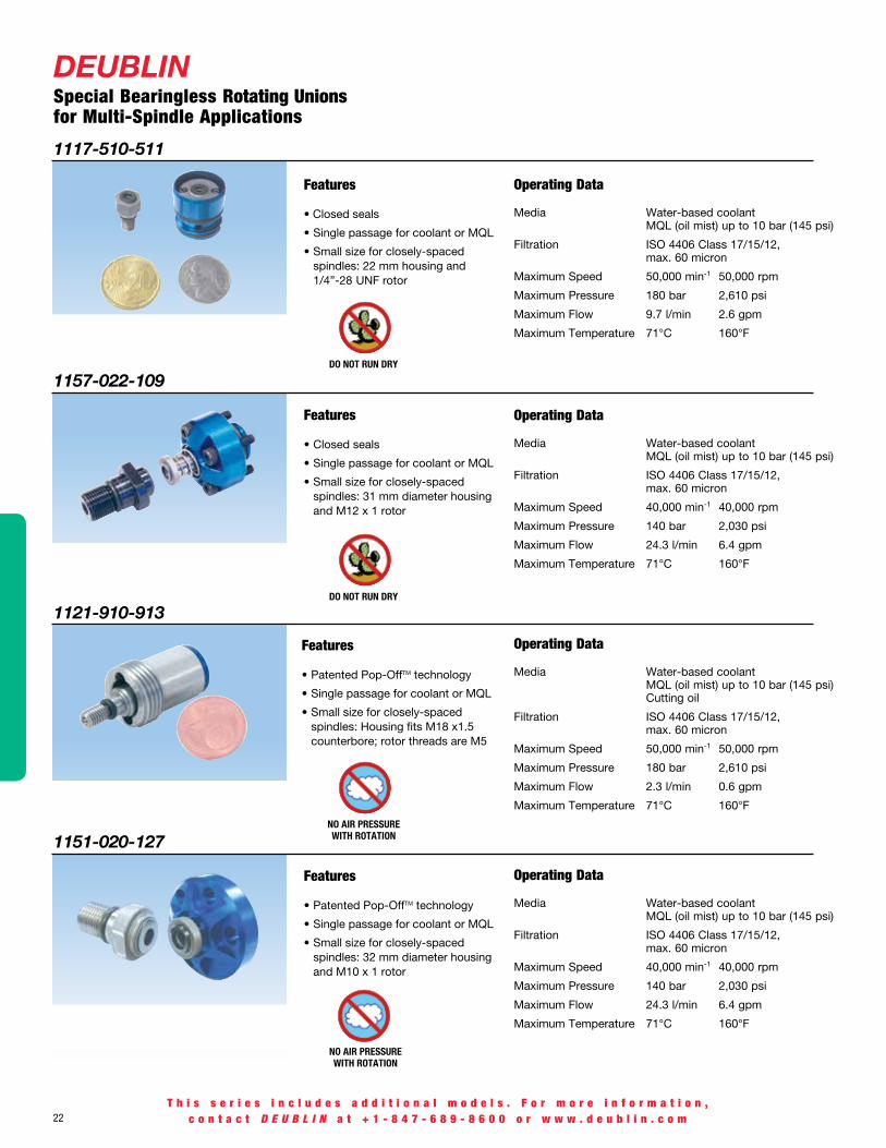
1121-910-913
1117-510-511
1157-022-109
1151-020-127
Operating Data
Media Water-based coolant MQL (oil mist) up to 10 bar (145 psi) Cutting oil
Filtration ISO 4406 Class 17/15/12, max. 60 micron
Maximum Speed 50,000 min-1 50,000 rpm
Maximum Pressure 180 bar 2,610 psi
Maximum Flow 2.3 l/min 0.6 gpm
Maximum Temperature 71°C 160°F
Features
• Closed seals
• Single passage for coolant or MQL
• Small size for closely-spaced spindles: 22 mm housing and 1/4”-28 UNF rotor
Features
Features
Features
DEUBLINSpecial Bearingless Rotating Unions for Multi-Spindle Applications
Operating Data
Media Water-based coolant MQL (oil mist) up to 10 bar (145 psi)
Filtration ISO 4406 Class 17/15/12, max. 60 micron
Maximum Speed 50,000 min-1 50,000 rpm
Maximum Pressure 180 bar 2,610 psi
Maximum Flow 9.7 l/min 2.6 gpm
Maximum Temperature 71°C 160°F
Operating Data
Media Water-based coolant MQL (oil mist) up to 10 bar (145 psi)
Filtration ISO 4406 Class 17/15/12, max. 60 micron
Maximum Speed 40,000 min-1 40,000 rpm
Maximum Pressure 140 bar 2,030 psi
Maximum Flow 24.3 l/min 6.4 gpm
Maximum Temperature 71°C 160°F
Operating Data
Media Water-based coolant MQL (oil mist) up to 10 bar (145 psi)
Filtration ISO 4406 Class 17/15/12, max. 60 micron
Maximum Speed 40,000 min-1 40,000 rpm
Maximum Pressure 140 bar 2,030 psi
Maximum Flow 24.3 l/min 6.4 gpm
Maximum Temperature 71°C 160°F
T h i s s e r i e s i n c l u d e s a d d i t i o n a l m o d e l s . F o r m o r e i n f o r m a t i o n ,c o n t a c t D E U B L I N a t + 1 - 8 4 7 - 6 8 9 - 8 6 0 0 o r w w w . d e u b l i n . c o m
NO AIR PRESSURE WITH ROTATION
DO NOT RUN DRY
NO AIR PRESSURE WITH ROTATION
DO NOT RUN DRY
• Closed seals
• Single passage for coolant or MQL
• Small size for closely-spaced spindles: 31 mm diameter housing and M12 x 1 rotor
• Patented Pop-OffTM technology
• Single passage for coolant or MQL
• Small size for closely-spaced spindles: Housing fits M18 x1.5 counterbore; rotor threads are M5
• Patented Pop-OffTM technology
• Single passage for coolant or MQL
• Small size for closely-spaced spindles: 32 mm diameter housing and M10 x 1 rotor

DEUBLIN23
T h i s s e r i e s i n c l u d e s a d d i t i o n a l m o d e l s . F o r m o r e i n f o r m a t i o n ,c o n t a c t D E U B L I N a t + 1 - 8 4 7 - 6 8 9 - 8 6 0 0 o r w w w . d e u b l i n . c o m
DEUBLIN1121 Series Bearingless Pop-OffTM “Micro Stroke” Rotating Unions for Coolant Service• Single passage for coolant or MQL• Patented Pop-OffTM technology allows unlimited dry running without media pressure• Ultra-short 0.1 mm pop-off stroke restricts drainage of residual coolant during tool change• Full-flow design has no obstructions to trap chips or debris• Balanced mechanical seals made from silicon carbide for long life even under difficult operating conditions• Anodized aluminum housing resists corrosionOperating Data
Media Water-based Coolant MQL (oil mist) up to 10 bar (145 psi)
Filtration ISO 4406 Class 17/15/12, max. 60 micron
Maximum Speed 40,000 min-1 40,000 rpm Standard 50,000 min-1 50,000 rpm High Pressure (HP)
Maximum Pressure 140 bar 2,030 psi
Maximum Flow 24.3 l/min 6.4 gpm 1121-330-327 38.7 l/min 10.2 gpm 1121-330-345 82 l/min 21.6 gpm
Maximum Temperature 71°C 160°F
Dual
Con
nect
ion
Axia
l Con
nect
ion
Stan
dard
HP
B C D L A E G H I M Max Ordering Supply Overall Overall Mounting Rotor Rotor Bore Across Pilot Pilot Speed Number Connection Diameter Length Distance Connection Length Diameter Flats Diameter Length (rpm)
B
B
D
ØC
LH
ØI A ØG
M
E
Dual Connection Axial Connection
D
E
M
BLH
ØI A Ø
G
ØC
NO AIR PRESSURE WITH ROTATION
G 3/8" Radial 1/4" PT AxialG 3/8" Radial 1/4" PT Axial
Mounting Distance
Mounting Distance
1121-300-327 3/8" PT 54 94 39.6 / 38.6 M12 x 1.25 LH 37 6 18 14.000 / 13.995 5 40,000
1121-300-345 3/8" PT 54 97 44.0 / 43.0 M16 x 1.5 LH 40 9 21 17.993 / 17.988 5 40,000
1121-330-327 3/8" PT 54 94 39.6 / 38.6 M12 x 1.25 LH 37 6 18 14.000 / 13.995 5 40,000
1121-330-345 3/8" PT 54 97 44.0 / 43.0 M16 x 1.5 LH 40 9 21 17.993 / 17.988 5 40,000
1121-380-327 54 98 39.6 / 38.6 M12 x 1.25 LH 37 6 18 14.000 / 13.995 5 40,000
1121-380-345 54 102 44.0 / 43.0 M16 x 1.5 LH 40 9 21 17.993 / 17.988 5 40,000
1121-400-327 3/8" PT 54 94 39.6 / 38.6 M12 x 1.25 LH 37 6 18 14.000 / 13.995 5 40,000
1121-400-345 3/8" PT 54 98 44.0 / 43.0 M16 x 1.5 LH 40 9 21 17.993 / 17.988 5 40,000
1121-410-493 3/8" PT 54 105 39.6 / 38.6 M12 x 1.25 LH 40 5 18 14.000 / 13.995 5 50,000
1121-430-431 3/8" PT 54 108 44.0 / 43.0 M16 x 1.5 LH 43 5 21 17.993 / 17.988 5 50,000

24
DEUBLIN1129 Series Bearingless Pop-OffTM Rotating Unions for Coolant Service• Single passage for coolant or MQL• Patented Pop-OffTM technology allows unlimited dry running without media pressure• Pop-off stroke of 0.7-3.0 mm compensates for thermal expansion of spindle during extended operation as well as variations in drawbar position• Full-flow design has no obstructions to trap chips or debris• Balanced mechanical seals made from silicon carbide for long life even under difficult operating conditions• Anodized aluminum housing resists corrosion
Operating Data
Media Water-based Coolant MQL (oil mist) up to 10 bar (145 psi)
Filtration ISO 4406 Class 17/15/12, max. 60 micron
Maximum Speed 30,000 min-1 30,000 rpm Standard 46,000 min-1 46,000 rpm High Pressure (HP)
Maximum Pressure 140 bar 2,030 psi
Maximum Flow 24.3 l/min 6.4 gpm 1129-016-301 53.0 l/min 14.0 gpm
Maximum Temperature 71°C 160°F
Dual
Con
nect
ion
Axia
l Con
nect
ion
Stan
dard
HP
B C D L A E G H I M Max Ordering Supply Overall Overall Mounting Rotor Rotor Bore Across Pilot Pilot Speed Number Connection Diameter Length Distance Connection Length Diameter Flats Diameter Length (rpm)
B
B
ØC
D
E
M
ØI
A ØG
H L
Dual Connection Axial ConnectionD
E
M
BLH
ØI A Ø
G ØC
T h i s s e r i e s i n c l u d e s a d d i t i o n a l m o d e l s . F o r m o r e i n f o r m a t i o n ,c o n t a c t D E U B L I N a t + 1 - 8 4 7 - 6 8 9 - 8 6 0 0 o r w w w . d e u b l i n . c o m
NO AIR PRESSURE WITH ROTATION
Mounting Distance Mounting
Distance
30 mm Counterbore
20 mm Counterbore
1129-033-301 3/8" PT 54 97 44.0 / 43.0 M16 x 1.5 LH 40 9 24 17.993 / 17.988 5 30,000
1129-033-327 3/8" PT 54 94 39.6 / 38.6 M12 x 1.25 LH 37 6 18 14.000 / 13.995 5 30,000
1129-050-301 G 3/8" 54 101 44.0 / 43.0 M16 x 1.5 LH 40 9 24 17.993 / 17.988 5 30,000
1129-859-731 G 3/8" 54 106 39.2 / 38.8 M12 x 1.25 LH 37 5 18 14.000 / 13.995 5 30,000
1129-016-301 3/8" PT 54 97 44.0 / 43.0 M16 x 1.5 LH 40 9 24 17.993 / 17.988 5 30,000
1129-036-301 3/8" PT 54 98 44.0 / 43.0 M16 x 1.5 LH 40 9 24 17.993 / 17.988 5 30,000
1129-036-327 3/8" PT 54 94 39.6 / 38.6 M12 x 1.25 LH 37 6 18 14.000 / 13.995 5 30,000
1129-039-301 3/8" PT 54 97 44.0 / 43.0 M16 x 1.5 LH 40 9 24 17.993 / 17.988 5 30,000
1129-730-731 G 3/8" 54 94 39.2 / 38.8 M12 x 1.25 LH 37 5 18 14.000 / 13.995 5 30,000
1129-927-929 G 3/8" 54 101 39.2 / 38.8 M14 x 1.5 LH 37 7 24 14.494 / 14.489 5 30,000
1129-330-342 48 72 37.5 M12 x 1 RH 28 6 22.2 13.000 / 12.992 7 20,000
1129-053-137 40 63 27.0/24.0 M12 x 1.25 LH 28 6 17 13.000 / 12.995 6 46,000

DEUBLIN25
Bearingless Rotating Unions Available ConfigurationsDEUBLIN bearingless Pop-OffTM unions are available to fit virtually every machine tool in the world. Shown below are only some of the many configurations available from DEUBLIN.
Outboard MountingWith outboard mounting, the union housing is installed from outside the spindle. Replacement is faster and easier with this mounting style.
Inboard MountingWith inboard mounting, the union housing is installed inside the spindle, typically within or near the tool clamping unit. Because a hose connection is not required, this mounting style can be very compact.
DEUBLIN1129 Series Bearingless “Controlled Leakage” Rotating Unions for Dry Air at High Speed• Single passage for dry or lubricated air
Operating DataMedia Air (dry or lubricated)Maximum Speed 20,000 min-1 20,000 rpmMaximum Pressure 10 bar 145 psiMaximum Temperature 71°C 160°F
Axia
l
B C D L A E G H I M Max Ordering Supply Overall Overall Mounting Rotor Rotor Bore Across Pilot Pilot Speed Number Connection Diameter Length Distance Connection Length Diameter Flats Diameter Length (rpm)
30 f7 Counterbore
30 f7 Counterbore
44 e8 Counterbore
D
M
E
H
L
ØI A
ØG
ØB
ØC
L
D
E
M
H
ØI A Ø
G
ØCB
D
E
M
B
LH
ØI A Ø
G
ØC
B
LH
D
E
M
ØI
ØG
ØCA
Dual Port
Axial Port
Counterbore
Threaded
T h i s s e r i e s i n c l u d e s a d d i t i o n a l m o d e l s . F o r m o r e i n f o r m a t i o n ,c o n t a c t D E U B L I N a t + 1 - 8 4 7 - 6 8 9 - 8 6 0 0 o r w w w . d e u b l i n . c o m
Mounting Distance
Mounting Distance
Mounting Distance
Mounting Distance
1129-051-482 48 72 40 M12 x 1 RH 33 6 17 12.994 / 12.989 6 20,000
1129-490-489 48 84 40.8 / 40.2 M12 x 1 RH 40 6 19 13.000 / 12.995 15 20,000
1129-775 44 63 38.5 12 e7 25 7 NA 11.984 / 11.966 24 20,000
DRY AIR SERVICE

26
DEUBLIN1154 Series Bearingless AutoSenseTM “Long Stroke” Rotating Unions for Coolant and Air Service• Single passage for coolant or MQL• Patent-pending AutoSenseTM technology automatically changes between closed seals and controlled leakage operation in response to the kind of media• Non-rotating element has a “stroke” (axial movement) of more than 8 mm, to track drawbar movement even when union is mounted on the clamping device• Full-flow design has no obstructions to trap chips or debris• Balanced mechanical seals made from silicon carbide for long life even under difficult operating conditions• Anodized aluminum housing resists corrosion
Operating Data
Media Water-based Coolant MQL (oil mist) up to 10 bar (145 psi) Air up to 10 bar (145 psi)
Filtration ISO 4406 Class 17/15/12, max. 60 micron
Maximum Speed 40,000 min-1 40,000 rpm
Maximum Pressure 140 bar 2,030 psi
Maximum Flow 24.3 l/min 6.4 gpm
Maximum Temperature 71°C 160°F
Axia
l
B C D L A E G H I M Max Ordering Supply Overall Overall Mounting Rotor Rotor Bore Across Pilot Pilot Speed Number Connection Diameter Length Distance Connection Length Diameter Flats Diameter Length (rpm)
M
DE
L
H
Ø1 A ØG
ØC
ØB
T h i s s e r i e s i n c l u d e s a d d i t i o n a l m o d e l s . F o r m o r e i n f o r m a t i o n ,c o n t a c t D E U B L I N a t + 1 - 8 4 7 - 6 8 9 - 8 6 0 0 o r w w w . d e u b l i n . c o m
1154-002-105 31 72 49.0 / 42.0 M8 x 1 RH 37 4 15 8.995 / 8.991 3.5 40,000
1154-002-109 31 63 37.0 / 30.0 M12 x 1 RH 28 5 15 12.994 / 12.989 6 40,000
1154-002-133 31 65 37.0 / 30.0 M16 x 1.5 LH 30 4 19 17.994 / 17.989 6 40,000
1154-002-140 31 63 37.0 / 30.0 M12 x 1.25 LH 28 5 15 12.994 / 12.989 6 40,000
1154-003-107 39 71 40.0 / 33.0 M12 x 1.25 LH 36 5 15 12.994 / 12.989 6 40,000
1154-003-137 38.5 62 31.0 / 25.0 M12 x 1.25 LH 27 5 15 12.994 / 12.989 6 40,000
1154-004-109 48.5 69 42.0 / 35.0 M12 x 1 RH 28 5 15 12.994 / 12.989 6 40,000
1154-005-109 31 87 49.0 / 42.0 M12 x 1 RH 28 5 15 12.994 / 12.989 6 40,000
1154-012-109A 31 63 37.0 / 30.0 M12 x 1 RH 28 5 15 12.994 / 12.989 6 40,000
1154-012-133A 31 65 37.0 / 30.0 M16 x 1.5 RH 30 5 19 17.994 / 17.989 6 40,000
Mounting Distance
16.4 mm Counterbore
16.4 mm Counterbore
16.4 mm Counterbore
16.4 mm Counterbore
20 mm Counterbore
20 mm Counterbore
16.4 mm Counterbore
30 mm Counterbore
16.4 mm Counterbore
Note A: 1154-012-xxx include a spring to fully retract the non-rotating element when pressure is discontinued. Note B: Overall Length (D) is at maximum Mounting Distance (L).
16.4 mm Counterbore

DEUBLIN27
DEUBLIN1139 Series Bearingless “All-Media” Rotating Unions for Coolant, MqL, and Air Service• Single passage for all media• Patented technology operates with closed seals for coolant, as a Pop-OffTM when pressure is removed, and as with a microscopic gap between the seals (“controlled leakage”) with pressurized dry air• Non-rotating element has a “stroke” (axial movement) of 0.7-3.0 mm, for reliable sealing even with thermal expansion of spindle and variations in drawbar position• Full-flow design has no obstructions to trap chips or debris• Balanced mechanical seals made from silicon carbide for long life even under difficult operating conditions• Anodized aluminum housing resists corrosionOperating Data
Media Water-based Coolant MQL (oil mist) Air, dry or lubricated
Filtration ISO 4406 Class 17/15/12, max. 60 micron
Maximum Speed 30,000 min-1 30,000 rpm
Maximum Pressure 140 bar 2,030 psi Coolant 10 bar 145 psi MQL, Air
Maximum Flow 28 l/min 7.4 gpm
Maximum Temperature 71°C 160°F
B C D L A E F G H I M Ordering Supply Overall Overall Mounting Rotor Rotor Thread Bore Across Pilot Pilot Number ConnectionA Diameter Length Distance Connection Length Length Diameter Flats Diameter Length
Axia
l Con
nect
ion
Note A: All 1139 series have a 1/8" radial connection for the actuation port.
3/8" NPT Axial 1/8" NPT Radial3/8" PT Axial 1/8" PT Radial3/8" PT Axial 1/8" PT Radial3/8" PT Axial 1/8" PT Radial
G 3/8" Radial G 1/8" RadialG 3/8" Radial G 1/8" Radial
G 3/8" AxialG 1/8" Radial
Radi
al
T h i s s e r i e s i n c l u d e s a d d i t i o n a l m o d e l s . F o r m o r e i n f o r m a t i o n ,c o n t a c t D E U B L I N a t + 1 - 8 4 7 - 6 8 9 - 8 6 0 0 o r w w w . d e u b l i n . c o m
Recommended valve configuration to switch quickly among media
Mounting Distance
(Actuation)
(Media)
Ball Valve
1139-020-116 51 97 31.6 / 30.6 M16 x 1.5 LH 28 11 9 24 17.993 / 17.988 5
1139-032-301 54 109 44.0 / 43.0 M16 x 1.5 LH 40 11 9 24 17.993 / 17.988 5
1139-032-327 54 106 39.6 / 38.6 M12 x 1.25 LH 37 12 6 21 14.000 / 13.995 5
1139-041-301 54 109 44.0 / 43.0 M16 x 1.5 LH 40 11 9 24 17.993 / 17.988 5
1139-744-301 54 101 44.0 / 43.0 M16 x 1.5 LH 40 11 9 24 17.993 / 17.988 5
1139-746-301 54 108 44.0 / 43.0 M16 x 1.5 LH 40 11 9 24 17.993 / 17.988 5
1139-746-327 54 105 44.0 / 43.0 M12 x 1.25 LH 37 12 6 24 14.000 / 13.995 5

28
DEUBLIN2620 Series 2-Passage Rotating Unions for Various Media• Two independent passages for applications such as clamping and unclamping• Balanced mechanical seals for each passage provide long life and reduced torque even at maximum pressure• Closed seals provide continuous containment of media• Dual precision ball bearings for smooth operation• Labyrinth protection for ball bearings• Mountings options are compatible with DEUBLIN 2520 or 1579 series unions
Operating Data
Media See table
Filtration ISO 4406 Class 17/15/12, max. 60 micron
Maximum Speed 7,000 min-1 7,000 rpm
Maximum Pressure See table
Maximum Flow 69 l/min 18.2 gpm (per passage)
Maximum Temperature 71°C 160°F
T h i s s e r i e s i n c l u d e s a d d i t i o n a l m o d e l s . F o r m o r e i n f o r m a t i o n ,c o n t a c t D E U B L I N a t + 1 - 8 4 7 - 6 8 9 - 8 6 0 0 o r w w w . d e u b l i n . c o m
12021
4 x
Ø19
11
Ø19.
05-0
.05
Ø9.5
Ø54
12.7
8
Ø63
4x Ø11Ø90.5
Ø107.95-0.015
6x Ø8.8Ø60.3
Ø81-0.015
2x Ø6.4
6x 60°
Ø60
12627
11
(Ø18
.8)
(Ø36
.4) Ø6
3
Outer passage
Outer passage(Alternate Location) Inner passage
Outer passage
Outer passage(Alternate Location) Inner passage
2620-XXX-252 shown
With Ø 108 mm flanged rotor With Ø 88 mm flanged rotor With Ø 81 mm flanged rotor Inner Passage Outer Passage
Ordering Number
Supply Connections
Inner and Outer Passage
Ordering Number
Supply Connections
Inner Passage
Outer Passage
Ordering Number
Supply Connections
Inner and Outer Passage
MediaMax.
Pressure {bar}
MediaMax.
Pressure {bar}
Notes
2620-000-252 1/4 NPT 2620-002-940 G1/4" G1/4" 2620-000-157 1/4 NPT Hydraulic oil 100 Hydraulic oil 30
2620-100-252 1/4 NPT 2620-102-940 G3/8" G1/8" 2620-100-157 1/4 NPT Hydraulic oil 70 Air 6
2620-120-252 1/4 NPT 2620-122-940 G3/8" G1/8" 2620-120-157 1/4 NPT Hydraulic oil 70 Air 10
2620-200-252 1/4 NPT 2620-202-940 G3/8" G1/8" 2620-200-157 1/4 NPT Coolant 70 Air 6
2620-220-252 1/4 NPT 2620-222-940 G3/8" G1/8" 2620-220-157 1/4 NPT Coolant 70 Air 10
2620-300-252 1/4 NPT 2620-302-940 G1/4" G1/4" 2620-300-157 1/4 NPT Air 6 Hydraulic oil 40
2620-320-252 1/4 NPT 2620-322-940 G1/4" G1/4" 2620-320-157 1/4 NPT Air 10 Hydraulic oil 40
2620-400-252 1/4 NPT 2620-402-940 G1/4" G1/4" 2620-400-157 1/4 NPT Air 6 Coolant 40
2620-420-252 1/4 NPT 2620-422-940 G1/4" G1/4" 2620-420-157 1/4 NPT Air 10 Coolant 40
2620-500-252 1/4 NPT 2620-502-940 G3/8" G1/8" 2620-500-157 1/4 NPT Air 6 Air 6
2620-520-252 1/4 NPT 2620-522-940 G3/8" G1/8" 2620-520-157 1/4 NPT Air 10 Air 10
Air seals may be lubricated through oil cup or by using oiled air.
Air seals require no external lubrication.
Consult DEUBLIN regarding maximum speed.
DEUBLIN29
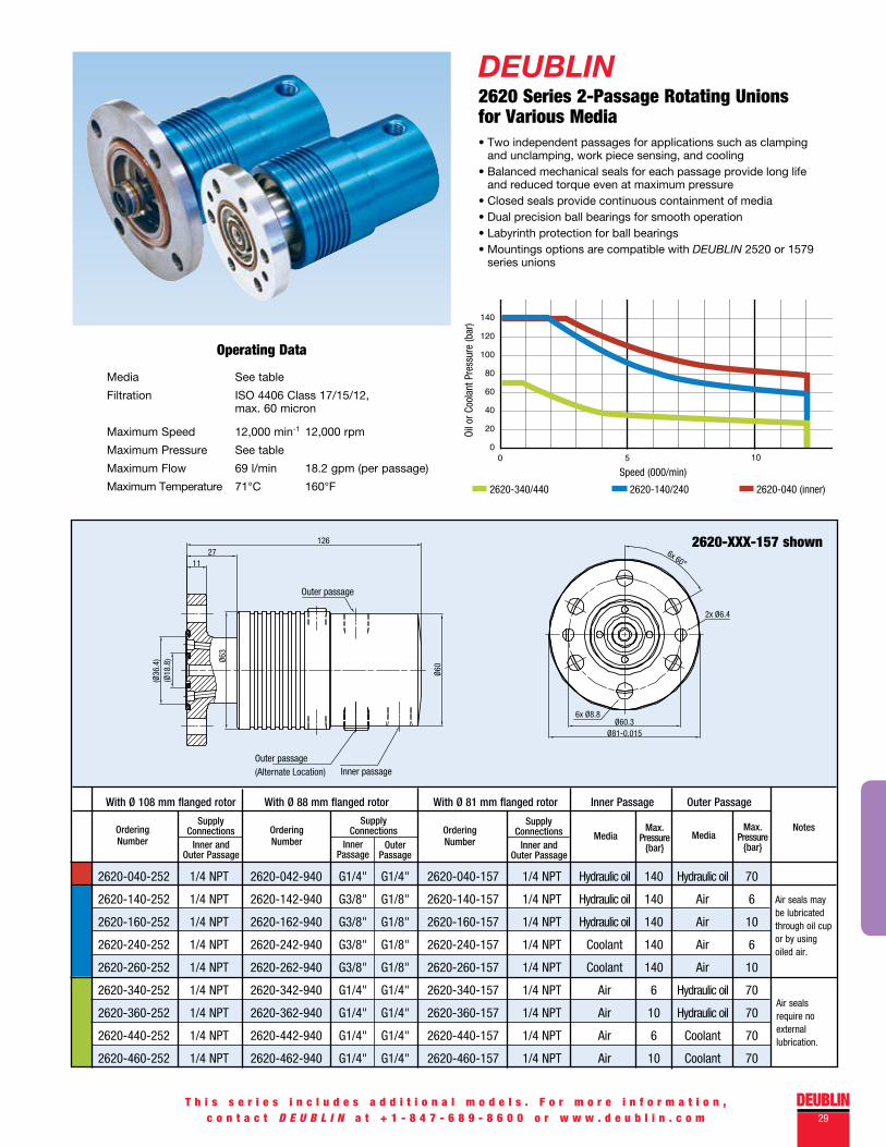
DEUBLIN2620 Series 2-Passage Rotating Unions for Various Media• Two independent passages for applications such as clamping and unclamping, work piece sensing, and cooling• Balanced mechanical seals for each passage provide long life and reduced torque even at maximum pressure• Closed seals provide continuous containment of media• Dual precision ball bearings for smooth operation• Labyrinth protection for ball bearings• Mountings options are compatible with DEUBLIN 2520 or 1579 series unions
Operating Data
Media See table
Filtration ISO 4406 Class 17/15/12, max. 60 micron
Maximum Speed 12,000 min-1 12,000 rpm
Maximum Pressure See table
Maximum Flow 69 l/min 18.2 gpm (per passage)
Maximum Temperature 71°C 160°F
T h i s s e r i e s i n c l u d e s a d d i t i o n a l m o d e l s . F o r m o r e i n f o r m a t i o n ,c o n t a c t D E U B L I N a t + 1 - 8 4 7 - 6 8 9 - 8 6 0 0 o r w w w . d e u b l i n . c o m
2620-XXX-157 shown
12021
4 x
Ø19
11
Ø19.
05-0
.05
Ø9.5
Ø54
12.7
8
Ø63
4x Ø11Ø90.5
Ø107.95-0.015
6x Ø8.8Ø60.3
Ø81-0.015
2x Ø6.4
6x 60°
Ø60
12627
11
(Ø18
.8)
(Ø36
.4) Ø6
3
Outer passage
Outer passage(Alternate Location) Inner passage
Outer passage
Outer passage(Alternate Location) Inner passage
With Ø 108 mm flanged rotor With Ø 88 mm flanged rotor With Ø 81 mm flanged rotor Inner Passage Outer Passage
Ordering Number
Supply Connections
Inner and Outer Passage
Ordering Number
Supply Connections
Inner Passage
Outer Passage
Ordering Number
Supply Connections
Inner and Outer Passage
MediaMax.
Pressure {bar}
MediaMax.
Pressure {bar}
Notes
2620-040-252 1/4 NPT 2620-042-940 G1/4" G1/4" 2620-040-157 1/4 NPT Hydraulic oil 140 Hydraulic oil 70
2620-140-252 1/4 NPT 2620-142-940 G3/8" G1/8" 2620-140-157 1/4 NPT Hydraulic oil 140 Air 6
2620-160-252 1/4 NPT 2620-162-940 G3/8" G1/8" 2620-160-157 1/4 NPT Hydraulic oil 140 Air 10
2620-240-252 1/4 NPT 2620-242-940 G3/8" G1/8" 2620-240-157 1/4 NPT Coolant 140 Air 6
2620-260-252 1/4 NPT 2620-262-940 G3/8" G1/8" 2620-260-157 1/4 NPT Coolant 140 Air 10
2620-340-252 1/4 NPT 2620-342-940 G1/4" G1/4" 2620-340-157 1/4 NPT Air 6 Hydraulic oil 70
2620-360-252 1/4 NPT 2620-362-940 G1/4" G1/4" 2620-360-157 1/4 NPT Air 10 Hydraulic oil 70
2620-440-252 1/4 NPT 2620-442-940 G1/4" G1/4" 2620-440-157 1/4 NPT Air 6 Coolant 70
2620-460-252 1/4 NPT 2620-462-940 G1/4" G1/4" 2620-460-157 1/4 NPT Air 10 Coolant 70
Air seals may be lubricated through oil cup or by using oiled air.
Air seals require no external lubrication.

30
DEUBLIN2630/2640 Series 3 to 5-Passage Rotating Unions for Various Media• Three to five independent passages for applications such
as clamping and unclamping, work piece or tool sensing, and spindle cooling
• Balanced mechanical seals in all passages for low torque and long life even with high speeds and pressures
• Closed seals provide continuous containment of media• No external lubrication of air seals is required• Dual precision ball bearings for smooth operation• Labyrinth protection for ball bearings
Operating DataMedia See table
Filtration ISO 4406 Class 17/15/12, max. 60 micron
Maximum Speed 10,000 min-1 10,000 rpm
Maximum Pressure Coolant or oil 140 bar 2,030 psi Air 10 bar 145 psi
Maximum Flow Per Passage 2630 Series 39 l/min 10.2 gpm 2640 Series 17 l/min 4.5 gpm 2650 Series 17 l/min 4.5gpm
Maximum Temperature 71°C 160°F
Note A: This passage features AutoSenseTM technology. With dry air, it operates with controlled leakage with MQL and coolant, it operates with closed seals.Note B: This passage operates with closed seals, appropriate for tool or work piece sensing applications.
Number of Passages Ordering Number Port #1 Port #2 Port #3 Port #4 Port #5
T h i s s e r i e s i n c l u d e s a d d i t i o n a l m o d e l s . F o r m o r e i n f o r m a t i o n ,c o n t a c t D E U B L I N a t + 1 - 8 4 7 - 6 8 9 - 8 6 0 0 o r w w w . d e u b l i n . c o m
3
4
2630-000-001 Hydraulic or Cooling Oil Drain Water Drain Coolant / MQL / Dry AirA
2630-100-001 Hydraulic or Cooling Oil Drain Hydraulic or Cooling Oil Drain Coolant / MQL / Dry AirA
2630-200-001 Hydraulic or Cooling Oil AirB Coolant Drain NA
2630-300-001 NA AirB Coolant AirB NA
2630-400-001 NA AirB Coolant Drain Coolant / MQL / Dry AirA
2640-000-001 Hydraulic or Cooling Oil AirB Coolant Drain Coolant / MQL / Dry AirA
2640-100-001 Hydraulic or Cooling Oil AirB Hydraulic or Cooling Oil Drain Coolant / MQL / Dry AirA
2650-000-001 Hydraulic or Cooling Oil AirB Coolant AirB Hydraulic or Cooling Oil
End View (2630-100-001 shown)
5
DEUBLIN31
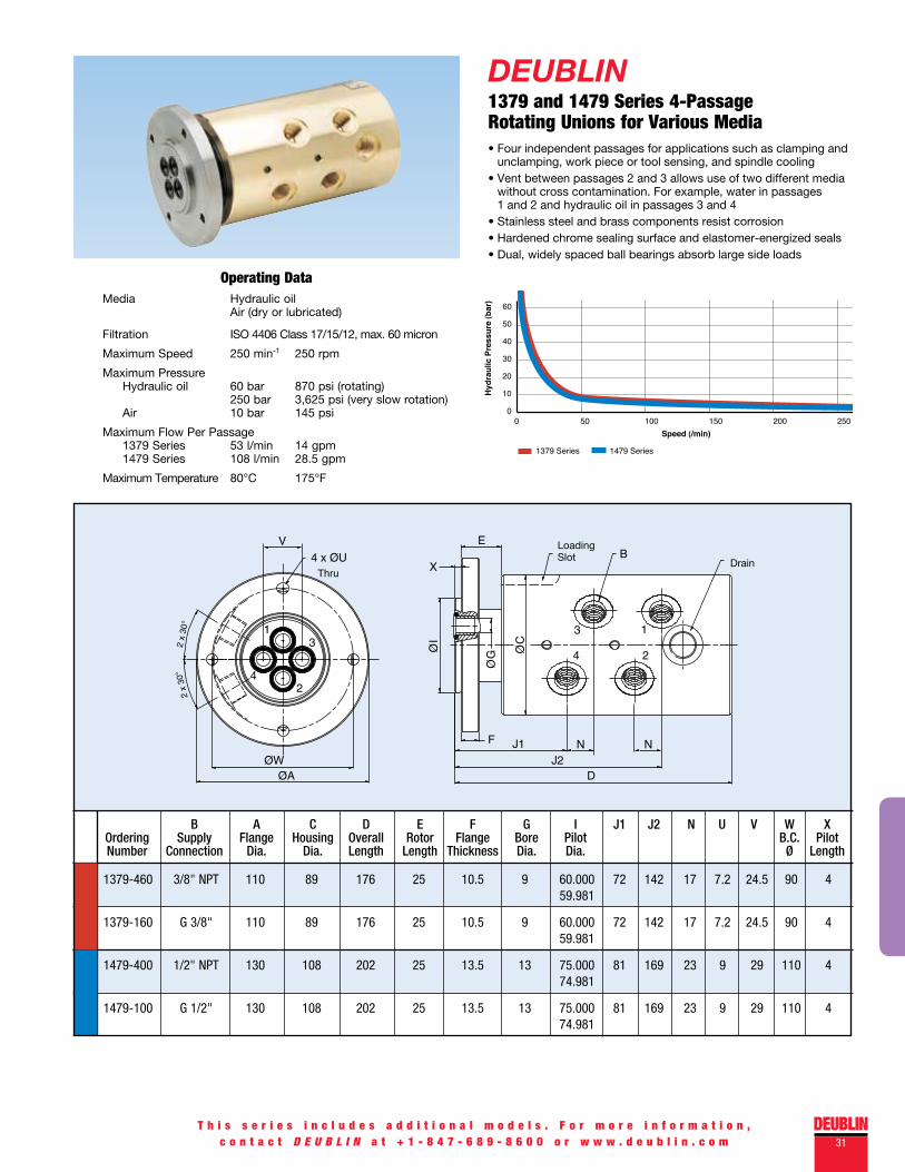
DEUBLIN1379 and 1479 Series 4-Passage Rotating Unions for Various Media• Four independent passages for applications such as clamping and unclamping, work piece or tool sensing, and spindle cooling• Vent between passages 2 and 3 allows use of two different media without cross contamination. For example, water in passages 1 and 2 and hydraulic oil in passages 3 and 4• Stainless steel and brass components resist corrosion• Hardened chrome sealing surface and elastomer-energized seals• Dual, widely spaced ball bearings absorb large side loads
Operating DataMedia Hydraulic oil Air (dry or lubricated) Filtration ISO 4406 Class 17/15/12, max. 60 micron
Maximum Speed 250 min-1 250 rpm
Maximum Pressure Hydraulic oil 60 bar 870 psi (rotating) 250 bar 3,625 psi (very slow rotation) Air 10 bar 145 psi
Maximum Flow Per Passage 1379 Series 53 l/min 14 gpm 1479 Series 108 l/min 28.5 gpm
Maximum Temperature 80°C 175°F
T h i s s e r i e s i n c l u d e s a d d i t i o n a l m o d e l s . F o r m o r e i n f o r m a t i o n ,c o n t a c t D E U B L I N a t + 1 - 8 4 7 - 6 8 9 - 8 6 0 0 o r w w w . d e u b l i n . c o m
Loading Slot Drain
Thru
1379-460 3/8" NPT 110 89 176 25 10.5 9 60.000 72 142 17 7.2 24.5 90 4 59.981
1379-160 G 3/8" 110 89 176 25 10.5 9 60.000 72 142 17 7.2 24.5 90 4 59.981
1479-400 1/2" NPT 130 108 202 25 13.5 13 75.000 81 169 23 9 29 110 4 74.981
1479-100 G 1/2" 130 108 202 25 13.5 13 75.000 81 169 23 9 29 110 4 74.981
B A C D E F G I J1 J2 N U V W X Ordering Supply Flange Housing Overall Rotor Flange Bore Pilot B.C. Pilot Number Connection Dia. Dia. Length Length Thickness Dia. Dia. Ø Length
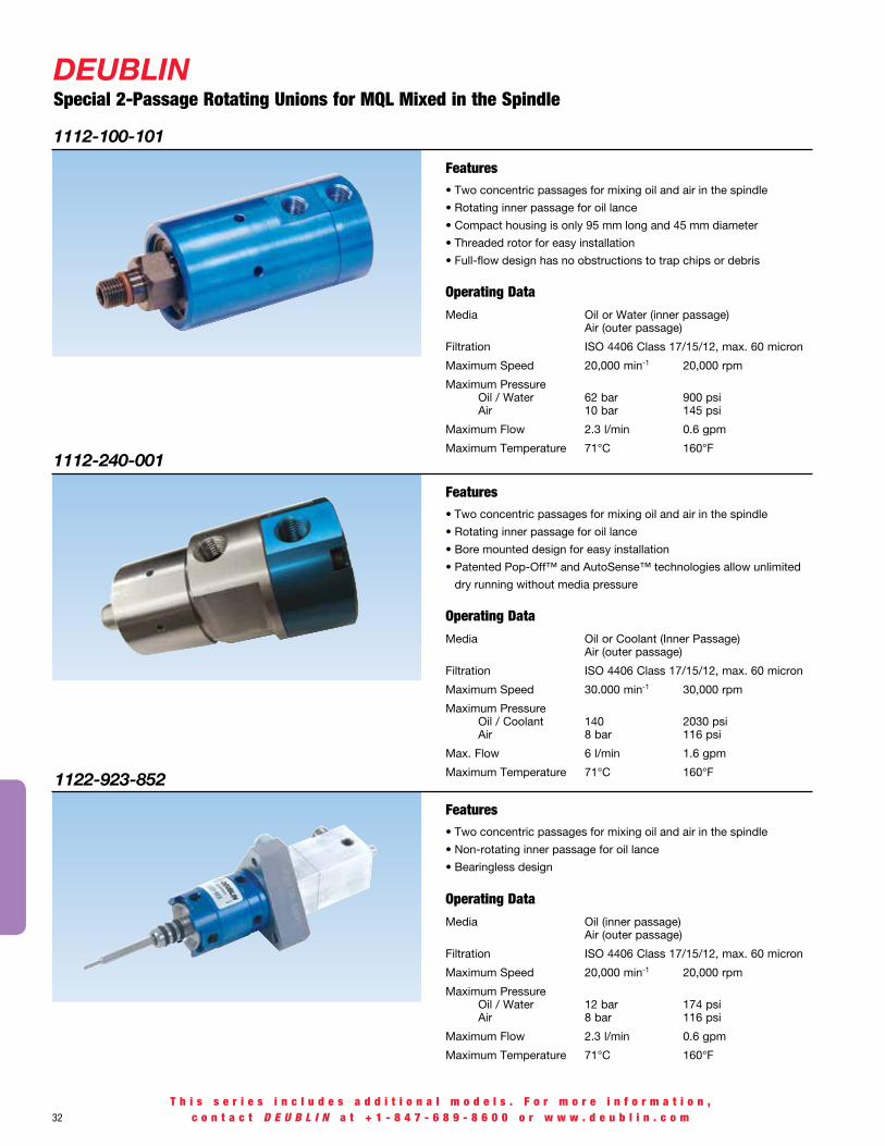
Media Oil or Water (inner passage) Air (outer passage)
Filtration ISO 4406 Class 17/15/12, max. 60 micron
Maximum Speed 20,000 min-1 20,000 rpm
Maximum Pressure Oil / Water 62 bar 900 psi Air 10 bar 145 psi
Maximum Flow 2.3 l/min 0.6 gpm
Maximum Temperature 71°C 160°F
1112-100-101
• Two concentric passages for mixing oil and air in the spindle
• Rotating inner passage for oil lance
• Compact housing is only 95 mm long and 45 mm diameter
• Threaded rotor for easy installation
• Full-flow design has no obstructions to trap chips or debris
Operating Data
Features
Media Oil (inner passage) Air (outer passage)
Filtration ISO 4406 Class 17/15/12, max. 60 micron
Maximum Speed 20,000 min-1 20,000 rpm
Maximum Pressure Oil / Water 12 bar 174 psi Air 8 bar 116 psi
Maximum Flow 2.3 l/min 0.6 gpm
Maximum Temperature 71°C 160°F
1122-923-852
• Two concentric passages for mixing oil and air in the spindle
• Non-rotating inner passage for oil lance
• Bearingless design
Operating Data
Features
32
DEUBLINSpecial 2-Passage Rotating Unions for MqL Mixed in the Spindle
T h i s s e r i e s i n c l u d e s a d d i t i o n a l m o d e l s . F o r m o r e i n f o r m a t i o n ,c o n t a c t D E U B L I N a t + 1 - 8 4 7 - 6 8 9 - 8 6 0 0 o r w w w . d e u b l i n . c o m
Media Oil or Coolant (Inner Passage) Air (outer passage)
Filtration ISO 4406 Class 17/15/12, max. 60 micron
Maximum Speed 30.000 min-1 30,000 rpm
Maximum Pressure Oil / Coolant 140 2030 psi Air 8 bar 116 psi
Max. Flow 6 l/min 1.6 gpm
Maximum Temperature 71°C 160°F
1112-240-001
• Two concentric passages for mixing oil and air in the spindle
• Rotating inner passage for oil lance
• Bore mounted design for easy installation
• Patented Pop-Off™ and AutoSense™ technologies allow unlimited
dry running without media pressure
Operating Data
Features

DEUBLIN33+ 1 - 8 4 7 - 6 8 9 - 8 6 0 0 o r w w w . d e u b l i n . c o m
Important Notice
The DEUBLIN Rotating Union is a precision-made piece of equipment and should be handled accordingly. It is a rotating sealing device – not just a plumbing union. Improper use or installation can result in premature leakage or failure. While DEUBLIN unions are of the highest quality and precision, they are “wear and tear” items. It is important that they are periodically inspected and, as the seals wear out, replaced or repaired to avoid the consequences of leakage.
DEUBLIN unions never should be used for applications other than as specified in the catalog. DEUBLIN unions should not be used to seal hydrocarbons or other flammable media as leakage may result in explosions or fires. The use of our product on hazardous or corrosive media is strictly forbidden.
Service and Support
Rotating unions are critical to the performance of your machining centers, so DEUBLIN products are designed for maximum reliability. DEUBLIN service is just as reliable. To provide you with local and emergency service, DEUBLIN has a worldwide service network of wholly-owned subsidiaries
and authorized distributors. Whether you need a spare part, new product, technical advice, or help with a design project, DEUBLIN’s experienced customer service representatives and application engineers are available to provide immediate assistance.
Factory Testing
All DEUBLIN Rotating Unions are factory-tested under pressure prior to shipment. This thorough check ensures that each DEUBLIN union performs as intended. DEUBLIN Rotating Unions can be installed with the confidence that they will operate to your complete satisfaction.
Warranty
For a period of one year from the date of shipment, DEUBLIN warrants that the products sold by it are free from defects in materials and workmanship. The liability of DEUBLIN is limited expressly to the replacement or rebuilding of any article, or part thereof, proven defective, when returned to the DEUBLIN Company, transportation prepaid, within a reasonable time after termination of the 365-day warranty period.
This warranty is void if the product is dismantled, modified, altered, or damaged from improper maintenance, side loading,
excessive temperature, abrasive or chemical action, or other abuse. No representative, agent, or employee of DEUBLIN has any authority to modify the terms of this warranty. DEUBLIN will not be responsible for any consequential or resulting damage which may be claimed to have occurred through the sale or use of such products or parts, thereof, which might be defective.
There are no warranties which extend beyond the description contained under this heading, express or implied, including warranties of fitness for a particular purpose.
For applications other than as stated in the catalog, contact DEUBLIN’s Engineering Department for recommendations.
These instructions are provided as general guidelines. They do not contain exhaustive information about the installation, use or maintenance of unions. Purchasers and users of DEUBLIN unions should be certain that they have reviewed DEUBLIN’s catalog and have sufficient experience and training in the use of unions before attempting installation or use of DEUBLIN products. The principal responsibility for the safe and effective use of DEUBLIN unions rests with the user and its employees. DEUBLIN will provide, upon request, whatever assistance it can to advise users about the use of its products and about any difficulties or problems which are brought to its attention.
WARRANTY AND OTHER IMPORTANT INFORMATION
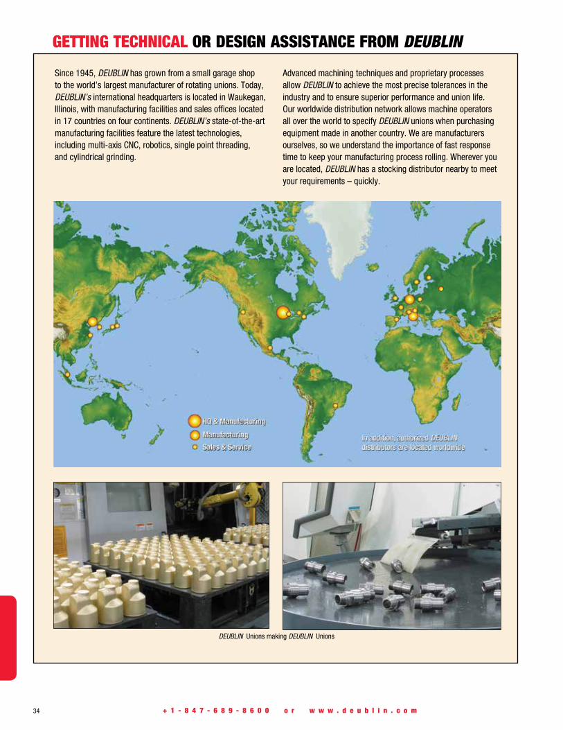
34 + 1 - 8 4 7 - 6 8 9 - 8 6 0 0 o r w w w . d e u b l i n . c o m
GETTING TECHNICAL OR DESIGN ASSISTANCE FROM DEUBLIN
Since 1945, DEUBLIN has grown from a small garage shop to the world’s largest manufacturer of rotating unions. Today, DEUBLIN’s international headquarters is located in Waukegan, Illinois, with manufacturing facilities and sales offices located in 17 countries on four continents. DEUBLIN’s state-of-the-art manufacturing facilities feature the latest technologies, including multi-axis CNC, robotics, single point threading, and cylindrical grinding.
Advanced machining techniques and proprietary processes allow DEUBLIN to achieve the most precise tolerances in the industry and to ensure superior performance and union life. Our worldwide distribution network allows machine operators all over the world to specify DEUBLIN unions when purchasing equipment made in another country. We are manufacturers ourselves, so we understand the importance of fast response time to keep your manufacturing process rolling. Wherever you are located, DEUBLIN has a stocking distributor nearby to meet your requirements – quickly.
DEUBLIN Unions making DEUBLIN Unions
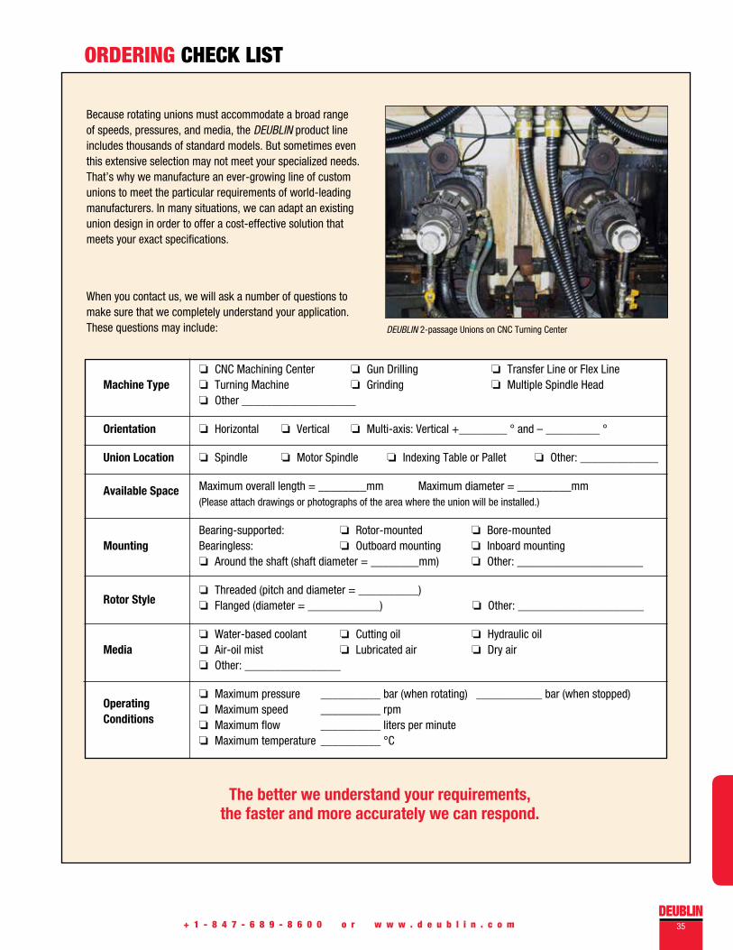
DEUBLIN35+ 1 - 8 4 7 - 6 8 9 - 8 6 0 0 o r w w w . d e u b l i n . c o m
ORDERING CHECk LIST
Because rotating unions must accommodate a broad range of speeds, pressures, and media, the DEUBLIN product line includes thousands of standard models. But sometimes even this extensive selection may not meet your specialized needs. That’s why we manufacture an ever-growing line of custom unions to meet the particular requirements of world-leading manufacturers. In many situations, we can adapt an existing union design in order to offer a cost-effective solution that meets your exact specifications.
When you contact us, we will ask a number of questions to make sure that we completely understand your application. These questions may include:
The better we understand your requirements, the faster and more accurately we can respond.
o CNC Machining Center o Gun Drilling o Transfer Line or Flex Line Machine Type o Turning Machine o Grinding o Multiple Spindle Head o Other ___________________
Orientation o Horizontal o Vertical o Multi-axis: Vertical +________ ° and – _________ °
Union Location o Spindle o Motor Spindle o Indexing Table or Pallet o Other: _____________
Available Space Maximum overall length = ________mm Maximum diameter = _________mm (Please attach drawings or photographs of the area where the union will be installed.)
Bearing-supported: o Rotor-mounted o Bore-mounted
Mounting Bearingless: o Outboard mounting o Inboard mounting o Around the shaft (shaft diameter = ________mm) o Other: _____________________
o Threaded (pitch and diameter = __________) Rotor Style o Flanged (diameter = ____________) o Other: _____________________
o Water-based coolant o Cutting oil o Hydraulic oil Media o Air-oil mist o Lubricated air o Dry air o Other: ________________
Operating o Maximum pressure __________ bar (when rotating) ___________ bar (when stopped)
Conditions
o Maximum speed __________ rpm o Maximum flow __________ liters per minute o Maximum temperature __________ °C
DEUBLIN 2-passage Unions on CNC Turning Center
americaSDEUBLIN USA 2050 Norman Drive Waukegan, IL 60085-6747 U.S.A. Phone: +1 847 689-8600 Fax: +1 847 689-8690 e-mail: [email protected] Brazil Rua Santo Antonio, 1426 - Vila Galvao Guarulhos, Sao Paulo Brazil 07071-000 Phone: +55 11-2455-3245 Fax: +55 11-2455-2358 e-mail: [email protected] Canada 3090 Boul. Le Carrefour, Suite 505 Laval, Quebéc H7T 2J7 Canada Phone: +1 514 745-4100 Fax: +1 514 745-8612 e-mail: [email protected] Mexico Norte 79-A No. 77, Col. Claveria 02080 Mexico, D.F. Phone: +52 55-5342-0362 Fax: +52 55-5342-0157 e-mail: [email protected]
aSiaDEUBLIN China No. 2, 6th DD Street, DD Port Dalian Liaoning Province, 116620, P.R. China Phone: +86 411-87549678 Fax: +86 411-87549679 e-mail: [email protected]
China Merchants Plaza 12th Floor, Suite (East) 1208, 333 Chengdubei Road Shanghai, 200041, P.R. China Phone: +86 21-52980791 Fax: +86 21-52980790 e-mail: [email protected]
Room 1302, Metro Plaza, No. 183 Tian He Bei RoadGuangZhou, 510620, P.R. ChinaPhone: +86 20-87569013Fax: +86 20-87569013 e-mail: [email protected] Asia Pacific 51 Goldhill Plaza, #11-11/12 Singapore 308900 Phone: +65 6259-9225 Fax: +65 6259-9723 email: [email protected] Japan 2-13-1, Minamihanayashiki Kawanishi City 666-0026, Japan Phone: +81 72-757-0099 Fax: +81 72-757-0120 e-mail: [email protected]
2-4-10-3F Ryogoku Sumida-Ku, Tokyo 130-0026, Japan Phone: +81 35-625-0777 Fax: +81 35-625-0888 e-mail: [email protected] Korea Star Tower #1003, Sangdaewon-dong 223-25, Jungwon-gu, Seongnam-si, Gyeonggi-do, South Korea Phone: +82-31-8018-5777 Fax: +82-31-8018-5780 e-mail: [email protected]
europeDEUBLIN Germany Nassaustraße 10 65719 Hofheim a. Ts., Germany Phone: +49 6122-8002-0 Fax: +49 6122-15888 e-mail: [email protected] Italy Via Guido Rossa 9 40050 Monteveglio (BO), Italy Phone: +39 051-835611 Fax: +39 051-832091 e-mail: [email protected]
Via Giovanni Falcone 36 20010 Bareggio (MI), Italy Phone: +39 02-90312711 Fax: +39 02-90278189 e-mail: [email protected] Austria Trazerberggasse 1/2 1130 Wien, Austria Phone: +43 1-8768450 Fax: +43 1-876845030 e-mail: [email protected] France 61 bis, Avenue de l‘Europe Z.A.C de la Malnoue 77184 Emerainville, France Phone: +33 1-64616161 Fax: +33 1-64616364 e-mail: [email protected] Poland ul. Kamienskiego 201-219 51-126 Wroclaw, Poland Phone: +48 71-3528152 Fax: +48 71-3207306 e-mail: [email protected] Russia ul. Kosygina, 13, 5th entrance, 1-st floor 119334, Moscow, Russia Phone: +7 495 647-14-34 Fax: +7 495 938-89-49 e-mail: [email protected] Spain C/Lola Anglada, 20 local 1, 08228 Terrassa, Spain Phone: +34 93-2211223 Fax: +34 93-2212093 e-mail: [email protected] Sweden Cylindervägen 18, Box 1113 13 126 Nacka Strand, Sweden Phone: +46 8 716 2033 Fax: +46 8 601 3033 e-mail: [email protected] United Kingdom 6 Sopwith Park, Royce Close, West Portway Andover SP10 3TS, UK Phone: +44 1264-333355 Fax: +44 1264-333304 e-mail: [email protected]
© Copyright 2012 DEUBLIN Company. All Rights Reserved.Printed in the U.S.A. MT123 US
DEUBLIN products & services are available throughout the world.
www.deublin.com
Since its establishment in 1945, DEUBLIN has consistently adhered to a policy of producing the best product of its kind in the market. The result of this policy has been constant growth through the years. For this progress we are grateful to our many loyal customers. We cordially invite you to visit our modern manufacturing facilities in Waukegan, Illinois; Hofheim a. Ts., Germany; Monteveglio, Italy; and Dalian, China.
Sincerely,
Donald L. DeublerChairman of the Board
Global Headquarters in Waukegan, Illinois, U.S.A.
Hofheim a. Ts., Germany
Monteveglio, Italy
Dalian, China


