Rotational particle separator : an efficient method to separate micron-sized droplets and particles from fluids Brouwers, J.J.H.; van Kemenade, H.P.; Kroes, J.P. Published in: Filtration Published: 01/01/2012 Document Version Accepted manuscript including changes made at the peer-review stage Please check the document version of this publication: • A submitted manuscript is the author's version of the article upon submission and before peer-review. There can be important differences between the submitted version and the official published version of record. People interested in the research are advised to contact the author for the final version of the publication, or visit the DOI to the publisher's website. • The final author version and the galley proof are versions of the publication after peer review. • The final published version features the final layout of the paper including the volume, issue and page numbers. Link to publication Citation for published version (APA): Brouwers, J. J. H., Kemenade, van, H. P., & Kroes, J. P. (2012). Rotational particle separator : an efficient method to separate micron-sized droplets and particles from fluids. Filtration, 12(1), 49-60. General rights Copyright and moral rights for the publications made accessible in the public portal are retained by the authors and/or other copyright owners and it is a condition of accessing publications that users recognise and abide by the legal requirements associated with these rights. • Users may download and print one copy of any publication from the public portal for the purpose of private study or research. • You may not further distribute the material or use it for any profit-making activity or commercial gain • You may freely distribute the URL identifying the publication in the public portal ? Take down policy If you believe that this document breaches copyright please contact us providing details, and we will remove access to the work immediately and investigate your claim. Download date: 12. Jun. 2018
Transcript
Rotational particle separator : an efficient method toseparate micron-sized droplets and particles from fluidsBrouwers, J.J.H.; van Kemenade, H.P.; Kroes, J.P.
Published in:Filtration
Published: 01/01/2012
Document VersionAccepted manuscript including changes made at the peer-review stage
Please check the document version of this publication:
• A submitted manuscript is the author's version of the article upon submission and before peer-review. There can be important differencesbetween the submitted version and the official published version of record. People interested in the research are advised to contact theauthor for the final version of the publication, or visit the DOI to the publisher's website.• The final author version and the galley proof are versions of the publication after peer review.• The final published version features the final layout of the paper including the volume, issue and page numbers.
Link to publication
Citation for published version (APA):Brouwers, J. J. H., Kemenade, van, H. P., & Kroes, J. P. (2012). Rotational particle separator : an efficientmethod to separate micron-sized droplets and particles from fluids. Filtration, 12(1), 49-60.
General rightsCopyright and moral rights for the publications made accessible in the public portal are retained by the authors and/or other copyright ownersand it is a condition of accessing publications that users recognise and abide by the legal requirements associated with these rights.
• Users may download and print one copy of any publication from the public portal for the purpose of private study or research. • You may not further distribute the material or use it for any profit-making activity or commercial gain • You may freely distribute the URL identifying the publication in the public portal ?
Take down policyIf you believe that this document breaches copyright please contact us providing details, and we will remove access to the work immediatelyand investigate your claim.
The rotational particle separator (RPS) has a cyclone type house within which a
rotating cylinder is placed. The rotating cylinder is an assembly of a large number of
axially oriented channels, e.g. small diameter pipes. Micron‐sized particles
entrained in the fluid flowing through the channels are centrifugated towards the
walls of the channels. Here they form a layer or film of particles material which is
removed by applying pressure pulses or by flowing of the film itself. Compared to
conventional cyclones the RPS is an order of magnitude smaller in size at equal
separation performance, while at equal size it separates particles ten times smaller.
Applications of the RPS considered are: ash removal from hot flue gases in small
scale combustion installations, product recovery in stainless environment for
pharma/food, oil water separation and demisting of gases. Elementary formulae for
separation performance are presented and compared with measurements performed
with various RPS design.
1 Introduction
Many processes require the separation of micron sized particles from a gas stream.
Techniques employed to do the job are: scrubbers, fabric filters, electrostatic
separators, and (multi‐)cyclones. There is still a drive however to develop new
technologies: scrubbers are sizeable and fail to remove micron‐sized particles, fabric
filters and electrostatic precipitators are limited to dry and/or chargeable particulate
matter and involve large installations, and cyclones in industrial installations subject
to large volume flows fail to collect micron sized particles [1]. A new development
which overcomes several of the aforementioned limitations is the rotational particle
separator, in short RPS [2]. The RPS has a cyclone type house within which a rotating
cylinder is placed. The rotating cylinder is an assembly of a large number of axially
oriented channels. These channels provide the means to collect micron sized particles
at limited rotational speed, pressure drop and short residence time (small building
volume).
In this paper we show the advantage of the RPS by comparing its performance
with that of vane type separators and cyclones (§ 2). In § 3 these considerations are
substantiated by results of experiments. Many RPS devices have been designed and
tested over the years and in section 4 to 6 the lessons learned concerning flow
stability, power consumption and loading/removal are discussed. § 7 and § 8 give
an overview of the designs that have been realized, while in § 9 the most recent
design, a gas scrubber for large volume operations is treated in more detail.
2 Elementaryseparation:vane‐typeseparator,cycloneandRPS We shall compare the separative performance of devices in which separation is the
result of inertial or centrifugal forces acting on particles with different density
compared to that of the fluid in which they are immersed.
The vane type separator is represented by a flow through a single bend (figure 1).
Three forces act on a particle moving along a curved trajectory with radius r and velocity v : the centrifugal force cF , a drag force dF and a buoyancy force buoF :
buodc FFF = . For particles with diameters ranging from about 0.5 micron to 25
micron, the fluid force can be described by Stokes flow. For smaller and larger
particles Cunningham and Reynolds number corrections have to be introduced,
respectively, however, at a diameter of 1 m, the effect is only ca. 10%, omitting it is
a more conservative approach [1]. The radial migration velocity of a particle can then
be described as
r
vdv tpFp
TC
18
)(=
22 (1)
p and F are the densities of the particle respectively the carrier fluid.
denotes the dynamic viscosity of the carrier fluid and tv the tangential velocity.
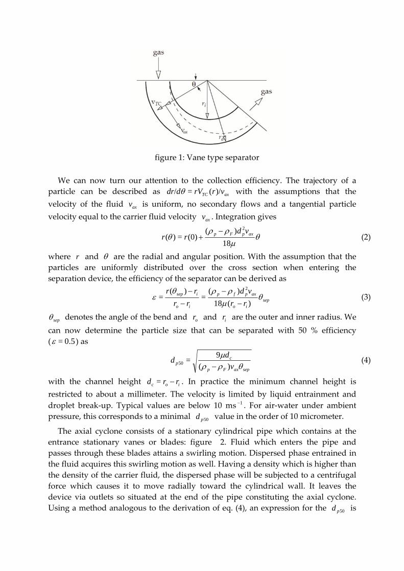
figure 1: Vane type separator
We can now turn our attention to the collection efficiency. The trajectory of a
particle can be described as axTC vrrVddr )/(=/ with the assumptions that the
velocity of the fluid axv is uniform, no secondary flows and a tangential particle
velocity equal to the carrier fluid velocity axv . Integration gives
18
)((0)=)(
2axpFp vd
rr
(2)
where r and are the radial and angular position. With the assumption that the
particles are uniformly distributed over the cross section when entering the
separation device, the efficiency of the separator can be derived as
sepio
axpfp
io
isep
rr
vd
rr
rr
)(18
)(=
)(=
2
(3)
sep denotes the angle of the bend and or and ir are the outer and inner radius. We
can now determine the particle size that can be separated with 50 % efficiency
( 0.5= ) as
sepaxFp
cp v
dd
)(
9=50
(4)
with the channel height ioc rrd = . In practice the minimum channel height is
restricted to about a millimeter. The velocity is limited by liquid entrainment and
droplet break‐up. Typical values are below 10 ms 1 . For air‐water under ambient
pressure, this corresponds to a minimal 50pd value in the order of 10 micrometer.
The axial cyclone consists of a stationary cylindrical pipe which contains at the
entrance stationary vanes or blades: figure 2. Fluid which enters the pipe and
passes through these blades attains a swirling motion. Dispersed phase entrained in
the fluid acquires this swirling motion as well. Having a density which is higher than
the density of the carrier fluid, the dispersed phase will be subjected to a centrifugal
force which causes it to move radially toward the cylindrical wall. It leaves the
device via outlets so situated at the end of the pipe constituting the axial cyclone.
Using a method analogous to the derivation of eq. (4), an expression for the 50pd is
given in [3]:
Lv
Rvd
tfp
axp 2
2
50 )2(
9=
(5)
tv is the tangential velocity , L the length of the cyclone and R the radius. To
derive this equation it is assumed that the axial velocity axv is constant over the
radius.
figure 2: Axial cyclone
Typical cyclones have a swirl ratio axt vvS /= of 1 to 2 and a L/R of about 5. The
axial velocity can be higher compared to the vane type: in the order of 20 ms 1 . The
only free parameter is now the radius: ie to achieve a 50pd of 10 micrometer the
radius has to be below 0.15 m. For higher volume flows multi cyclones have to be
used.
The inline version of the rotational particle separator (RPS) is an axial cyclone
within which a rotating separation element is built, figure 3. The rotating element
consists of a multitude of axially oriented channels of diameter of about 1 to 2 mm.
The separation process taking place in the channels of the RPS is similar to that in the
cyclone. In this case we can derive for 50pd [1]
Lv
Rdvd
tfp
caxp 250% )2(
27=
(6)
We can now compare the performance of the RPS to the vane separator by looking at
the ratio of 50pd for the same axial velocities
2
50,
50, 1
27
36= S
R
L
d
d
sepRPSp
vanep
(7)
While the separation angle is limited to about /2= sep , the ratios LR/ and
axt vvS /= can be used for the RPS to increase performance.
figure 3: Axial RPS
The 50pd of the cyclone compares to the 50pd of the RPS as
cRPSp
cycp
d
R
d
d
3=
50,
,50 (8)
Figure 4 depicts the 50pd under atmospheric pressure as a function of the volume
flow 2= RQ . The 50pd of the RPS remains constant below 1 micrometer, while the
cyclone 50pd quickly rises into the micrometer range. The rotational particle
separator is able to separate an order of magnitude smaller particles than the axial
cyclone is able to at equal flow and dimensions.
figure 4: diameter of water droplets in air separated by a cyclone and RPS as function
of the volume flow under atmospheric pressure
For equal separation performance we find the relation
cyclone
c
RPS
cyclone
R
d
R
R
3= (9)
This ratio is a measure for the difference in footprint or space between the cyclone
and RPS for an equal separation performance. For the same separation performance,
the size of the RPS can be an order lower compared to a cyclone.
3 ExperimentsTwo measurement methods were used to assess the performance of centrifugal
separators: laser diffraction and impactation. Laser diffraction is based on the
phenomenon that particles illuminates by a laser beam scatter light at angles that are
inversely proportional to the size of the particles. Large particles scatter at small
forward angles while small particles scatter light at wider angles. Mie theory is used
to establish the relation between the scattered energy distribution on the detectors
and the particle size distribution. In both cases the measurement set‐up is such that
the droplet distribution of a nozzle can be measured with and without the separator
in place. If the nozzle droplet distribution overlaps the separator cut‐off, the
separator efficiency as function of the size can be deduced from both droplet
distributions. The other apparatus used is a Anderson type cascade impactor
whereby particles within a size class are collected on a specific stage of the impactor
3.1 Moistureseparationpanel
As representative for bend‐type separators, we used a moisture separation panel
as applied to the inlet of turbo machinery. Based on the fixed dimensions of the laser
diffraction device, a square test duct with external dimensions of 220 mm was used
to guide the air and droplets to the water droplet panels and through a Malvern
Mastersizer S (Figure 5). Complying to standard installation, a fan was installed
downstream the duct. The laser measurement is located about 300 mm downstream
the outlet of the water droplet catcher panels to have sufficient mixing downstream
the separator panel without significant evaporation of the droplets. Adapter pieces
were constructed to allow both vertical and 15 installation. Before each spray
spectrum measurement is done, the setting of the fan is checked by measuring the
velocity in the middle of the duct with a hot wire measuring device. Analysis of the
moisture separator panels was done at 3 ms 1 and 5 ms 1 .
figure 5: Experimental set‐up
A typical measurement result is depicted in figure 6. Each datapoint represents
three measurements of both the nozzle distribution and the distribution after the
separator. Curve (1) is the measured droplet volume distribution without a separator
in the duct. Curve (2) is measured with the separator mounted between the nozzle
and the measuring spot. Curve (3) is curve (2) scaled to curve (1) using the measured
concentration. The probability P that a particle of a certain diameter passes through
the separator is found by dividing the values of curve (3) by those of curve (2). The
efficiency is equal to the probability that a particle is caught in the separator or
P1= . Conventionally the cut‐off diameter of a separator is characterized by the
diameter 50pd of the particle that has a 50% probability of passing through the
separator, 22 m in the case of figure 6.
figure 6: Typical measurement result: Curves (1) to (2) are the volume
distributions measured without and with separator present. Curve (3) is curve (2)
scaled to (1). The efficiency curve (4) is obtained as 1‐(3)/(1).
figure 7: Measured panel efficiency
The measured efficiencies scaled to their respective 50pd are presented in figure 7.
The three panel types have slightly different geometries but all panels essentially
depend on two bends for the removal of droplets. Consequently the curves overlap
each other despite their difference in 50pd . The exception is panel type 3 at the higher
velocity of 5 ms 1 , here re‐entrainment or flooding occurs, a phenomenon reported
in literature since 1939 [4]. It can be concluded that the 50pd indeed is a good
measure to compare the performance of geometrically similar moisture panels as the
efficiency distribution hardly changes.
3.2 Cyclone
The demisting stage of advanced gas‐liquid scrubber vessels usually consists of a
bank of axial cyclones (swirl tubes), working in parallel. We measured the efficiency
of a single commercial swirl tube in the way explained in the previous section. Since
the droplets leaving the cyclone are in the range 1‐10 micron, the lens of Malvernʹs
Mastersizer S was too small; instead we used the Spraytec.
During measurements the cyclone was contained in a bigger pipe (diameter 200
mm), simulating a scrubber vessel with upwards gas flow. Nozzles injected a
constant amount of water into an adjustable airflow. Droplet distributions and
concentrations were measured in the open outflow above this pipe. The efficiency is
determined taking a dummy cyclone (without swirl element, i.e. vanes and body
removed) as reference. Measurements were done at 11 flowrates, for which the
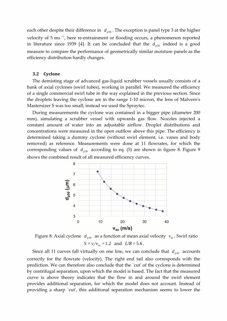
corresponding values of 50pd according to eq. (5) are shown in figure 8. Figure 9
shows the combined result of all measured efficiency curves.
Figure 8: Axial cyclone 50pd as a function of mean axial velocity axv . Swirl ratio
1.2=/= axt vvS and 5.6=/RL .
Since all 11 curves fall virtually on one line, we can conclude that 50pd accounts
correctly for the flowrate (velocity). The right end tail also corresponds with the
prediction. We can therefore also conclude that the `cutʹ of the cyclone is determined
by centrifugal separation, upon which the model is based. The fact that the measured
curve is above theory indicates that the flow in and around the swirl element
provides additional separation, for which the model does not account. Instead of
providing a sharp `cutʹ, this additional separation mechanism seems to lower the
distribution as a whole.
figure 9: Measured efficiency as a function of the particle size pd , made
nondimensionless with 50pd . Results below 3 micron were disregarded. Prediction is
based on plug flow, and a Rankine vortex profile with core radius R0.8 .
We have to remark that despite the fact that the mist separation efficiency was
conform expectations, or even somewhat better, the performance with regard to big
droplets ( 200> m) was inferior, resulting in a low overall efficiency (75% at the
design load). The higher the gas velocity, the larger the volume of large droplets that
we measured in the flow leaving the cyclone. The reason is that the centrifugal force
goes to zero at the stationary wall, which easily leads to re‐entrainment. Since the
RPS has a rotating collection wall, it does not suffer from this problem.
3.3 RPS
Many RPS devices have been designed and tested over the past 15 years [5, 6, 7]
e.g. ash removal from flue gas of combustion installations, air cleaning in domestic
appliances, product recovery in pharmaceutical and food industry and oil/water
separation.
Separation efficiencies have been assessed for a number of separation elements of
different size (length, radius, channel, height, etc.) subject to different conditions
The RPS facilitates various kinds of innovations in the process industry. An
example is the process of condensed rotational separation [8]. In this process
components of a gas‐gas mixture are condensed by fast reduction of temperature and
pressure. The resulting mist of micron‐sized droplets is removed by the RPS.
Applications foreseen are: upgrading of contaminated sour gas fields [8], removal of
CO2 from flue gases of coal fired power stations [16] and separation of heavy
fractions from natural gas. Core of all these applications is the RPS, designed as a
compact mist and aerosol catcher. It is discussed in more detail in section 9 below.
9 RPSGasscrubber The introduction of the RPS as a gas scrubbers in large volume applications [6]
presented a number of new design issues, the most important being the behaviour
under high pressure and the ability to cope with large liquid loads. As it is known
that centrifugal separation is process that is sensitive to design details that are easily
overlooked in CFD simulations, a visually accessible industrial scale prototype has
been built before taking the step to a field test. The prototype was connected to an
atmospheric test rig with water and air as working fluids. The test setup
approximately models a 24 m3/s (80 MMscf/d) equivalent installation on a natural
gas well. The design is suited for large liquid loads and is schematically depicted in
figure 15.
Gas containing a mist of droplets enters the unit via a tangential inlet. First coarse
droplets (larger than 10 micrometer) are separated in the pre‐separator section. The
pre‐separator acts as a cyclon and collects the droplets in a stationary volute. This
liquid leaves via a tangentially connected exit.
The gas stream, containing the remaining mist of mainly micron‐sized droplets,
enters the rotating element. In the design point the rotating element can be driven by
the impulse of the rotating flow. An external drive is can optionally be added to be
able to control the rotating speed independent of the incoming flow. While traveling
in the axial direction through the rotating channels, the droplets are driven to the
channel walls by centrifugal force. On the walls the mist droplets coagulate into a
thin fillm. The rotating element thus acts as a droplet coalescer. For optimal film
behavior and minimal pressure drop the flow direction through the element is
downward. Due to gravitational and shear forces, the film is forced out of the
channels.
At the end of the channels the film breaks up into droplets of typically 50
micrometer. The outer wall of the rotating element extends in the axial direction
beyond the end of the channels. This ensures that the solid body rotation of the gas
stream leaving the element is maintained. Droplets that break of at the end of the
channels are centrifugally separated from the gas in this rotating field, and collected
in a film on the rotating outer wall.
Downstream of the element the post‐separator section is entered, where the liquid
is actually separated from the gas stream. The liquid film leaves the gas stream at the
end of the extended outer wall of the rotating element towards a non‐rotating
collection volute. The liquid still contains significant momentum, which drives a
standing film within the stationary volute. Via a tangentially connected large
diameter exit the liquid leaves towards a collection vessel. The inner wall of the
collection volute keeps the liquid separated from the product gas flow. This wall
prevents re‐entrainment of liquid due to splashing in the post‐separator.
The RPS is designed to minimize any complexities involving rotation. This is
achieved by containing all rotating parts, including bearings, in a pressure resistant
pipe. There are no rotating shafts piercing through the wall needing rotating seals. If
an external drive is needed then this happens through a magnetic coupling.
Furthermore the rotating element is simple and straightforward of design implying
low mechanical stresses. One can easily design for a continuous lifetime of ten years
or longer
After assessing that the RPS performed to expectations regarding separation
efficiency and liquid removal [11] the test rig was modified to simulate the behaviour
at higher Reynolds numbers. It is known that non‐rotating pipe‐flow becomes
becomes turbulent due to finite amplitude disturbances for bulk Reynolds numbers
2000>Re . However, sufficient rotation causes the flow to become unstable against
infinitesimal disturbances already at 83=Re [15]. Therefore, rotating pipe flow is
characterized by two Reynolds numbers: the usual bulk Reynolds number
/= fcaxdvRe and an additional rotation Reynolds number /4= 2fcdRR which
comprises the rotation rate (rad/s), but is independent of the distance to the rotation axis. It should be realized that, although these conditions are sufficient for
the onset of instabilities, they need not correspond to the transition to turbulence.
An important implication of applying the RPS under pressure is a high gas density,
going with large Reynolds numbers. Since our laboratory test setup operates with air
at atmospheric pressure, we used an extra large channel diameter to achieve a higher
Reynolds number. Since the channel length to diameter ratio was kept constant, the
test unit had to be lengthened as well. Figure 16 shows a measurement result,
obtained using the method explained in section 3. It can be concluded that sufficient
separation is achieved, also in the unstable/turbulent regime. Compared to laminar
flow 50pd does not change, while the right hand side of the curve drops only
slightly, conform DNS simulations. We can now safely release the earlier restriction
of purely laminar flow.
Often the performance of a gas scrubber is presented in the form of a sizing or
load factor K as used in the Sounders‐Brown equation. The required gas scrubber
area (footprint) can than be calculated from
gl
lA
K
QA
= (11)
The load factor K is a direct measure for the required footprint of the installation
and has the unit of velocity. In figure 17 we have compared the best practice of
scrubbers with that of a RPS. Only under atmospheric pressure and a 50pd of 3
micrometer is the size of a cyclone deck comparable to that of a RPS. Otherwise the
RPS is significantly smaller and capable of separating particles in the submicron
range. Application of the RPS is thus particularly advantageous when working at
elevated pressures and large flows as is the case in the process of condensed
rotational separation (section 8).
10 Concludingremarks Main features of the rotational particle separator as a new device for separating
micron sized particles or droplets from carrier fluids have been presented.
Performance indicators as size of of particles separated, energy consumption per
unit throughflow and size of the unit compare favorably with conventional methods
based on vane separators and cyclones.
The RPS facilitates various innovations in process industry. An example is the
compact and energy efficient process of condensed rotational separation.
Acknowledgment The authors wish to thank Romico Hold for access to proprietary knowledge
regarding the RPS and related processes
References
[1] R.J.E. van Wissen, J.J.H. Brouwers, M. Golombok, In‐line centrifugal separation
of dispersed phases, AIChE Journal, 53(2), 374‐380, (2007)
[2] J.J.H. Brouwers, Particle collection efficiency of the rotational particle separator,