88
RotoProne Therapy System User Manual ...with people in mind 208662-AH Rev D • 05/2016

RotoProne Therapy SystemUser Manual
...with people in mind208662-AH Rev D • 05/2016


iii
TABLE OF CONTENTS
DISCLAIMER OF WARRANTY AND LIMITATION OF LIABILITY ...................................... vii
Introduction
Indications for Use ...................................................................................................1-1
Contraindications ....................................................................................................1-1
Risks and Precautions ..............................................................................................1-2
Safety Information ...................................................................................................1-3
Operating Instructions
RotoProne Therapy System Overview .....................................................................2-1
Power-Up Procedure ................................................................................................2-2
Welcome To RotoProne / New Patient Screen .........................................................2-3
Home Screen ...........................................................................................................2-3
Prone / Supine Button and Prone / Supine Preparation ............................................2-4
- Checklist...........................................................................................................2-5
Move To Prone / Supine .........................................................................................2-6
Therapy Settings Selection .....................................................................................2-7
- Prone / Supine Settings .....................................................................................2-8
- Therapy Settings Definitions..............................................................................2-8
Scale ......................................................................................................................2-9
- Hold Patient Weight .........................................................................................2-9
- Zero Scale .......................................................................................................2-10
- Display ...........................................................................................................2-10
- Weigh Delay ...................................................................................................2-10
- Adjusted Weight .............................................................................................2-11
- Weight Trends ................................................................................................2-11
Surface Position ...................................................................................................2-12
- Surface Height ................................................................................................2-12
- Trendelenburg / Reverse Trendelenburg ...........................................................2-12
Park .....................................................................................................................2-13
iv
- Park Positions .................................................................................................2-13
- Therapy Meters...............................................................................................2-14
- Therapy Chart.................................................................................................2-15
Powered CPR .........................................................................................................2-15
Emergency Release for CPR / Supine Position .........................................................2-17
Manual Rotation to Prone Instructions ...................................................................2-19
Help ......................................................................................................................2-20
Hand Control ........................................................................................................2-20
Alarms and Troubleshooting ..................................................................................2-21
In Case of Stuck or Jammed Lock Pin ...................................................................2-27
Patient Placement
Preparation for Patient Placement ............................................................................3-1
- Therapy Settings Definitions..............................................................................3-4
Patient Transfer to the RotoProne Therapy System ................................................3-10
Pack Installation .....................................................................................................3-12
Leg Abductor Pack ...............................................................................................3-12
Side Support Packs...............................................................................................3-13
Proning Packs ......................................................................................................3-16
Assess Patient Position .........................................................................................3-19
Face Pack .............................................................................................................3-19
Chest Packs .........................................................................................................3-21
Completion of Patient Placement ...........................................................................3-21
Starting Therapy ....................................................................................................3-23
Prone Therapy .......................................................................................................3-25
Patient Care
Hatches ...................................................................................................................4-1
Upper Body Hatches ..............................................................................................4-1
Hatch Center Bar (X-ray Facilitation) .......................................................................4-1
Midline Hatch ........................................................................................................4-2
Lower Body Hatch..................................................................................................4-2
Bathing Patient ........................................................................................................4-3
Supine Bathing ......................................................................................................4-3

v
Prone Bathing ........................................................................................................4-4
Skin Care .................................................................................................................4-5
Face .......................................................................................................................4-5
Axilla .....................................................................................................................4-5
Shoulders and Iliac Crest ........................................................................................4-6
Feet .......................................................................................................................4-6
Incontinence / Drainage ...........................................................................................4-6
Foot Support ...........................................................................................................4-6
Side-Lying Head Position ..........................................................................................4-6
Patient Transfer From the RotoProne Therapy System ...............................................4-7
Power-Down Procedures
Power-Down for Intra-Facility Transport / Storage ...................................................5-1
Power-Down for Shipping ......................................................................................5-3
Care and Cleaning
Daily Equipment Check ............................................................................................6-1
Preventive Maintenance ...........................................................................................6-1
Specifications *
Recommended Weight and Height ........................................................................7-1
Dimensions ............................................................................................................7-1
Articulation ............................................................................................................7-1
Scale ......................................................................................................................7-1
Electrical ................................................................................................................7-1
Classification..........................................................................................................7-1
Environmental Storage / Transit Conditions ............................................................7-2
Environmental Operating Conditions ......................................................................7-2
Symbols Used ..........................................................................................................7-2
Electromagnetic Emissions Information ....................................................................7-4
Questions and Information
Contact Information ................................................................................................8-1

vii
DISCLAIMER OF WARRANTY AND LIMITATION OF LIABILITY
ARJOHUNTLEIGH HEREBY DISCLAIMS ALL EXPRESS OR IMPLIED WARRANTIES, INCLUDING WITHOUT LIMITATION ANY IMPLIED WARRANTY OF MERCHANTABILITY OR FITNESS FOR A PARTICULAR PURPOSE, ON THE ARJOHUNTLEIGH PRODUCT(S) DESCRIBED IN THIS PUBLICATION. ANY WRITTEN WARRANTY OFFERED BY ARJOHUNTLEIGH SHALL BE EXPRESSLY SET FORTH IN THIS PUBLICATION OR INCLUDED WITH THE PRODUCT. UNDER NO CIRCUMSTANCES SHALL ARJOHUNTLEIGH BE LIABLE FOR ANY INDIRECT, INCIDENTAL, OR CONSEQUENTIAL DAMAGES AND EXPENSES, INCLUDING DAMAGES OR INJURY TO PERSON OR PROPERTY, DUE IN WHOLE OR IN PART TO THE USE OF THE PRODUCT OTHER THAN THOSE FOR WHICH DISCLAIMER OF WARRANTY OR LIMITATION OF LIABILITY IS EXPRESSLY PROHIBITED BY SPECIFIC, APPLICABLE LAW. NO PERSON HAS THE AUTHORITY TO BIND ARJOHUNTLEIGH TO ANY REPRESENTATION OR WARRANTY EXCEPT AS SPECIFICALLY SET FORTH IN THIS PARAGRAPH.
Descriptions or specifications in ArjoHuntleigh printed matter, including this publication, are meant solely to generally describe the product at the time of manufacture and do not constitute any express warranties, except as set forth in the written limited warranty included in this publication or with this product. Information in this publication may be subject to change at any time. Contact ArjoHuntleigh for updates.
IMPORTANT INFORMATION FOR USERS
In order for ArjoHuntleigh products to perform properly, ArjoHuntleigh recommends compliance with the following conditions. Failure to comply with these conditions will void any applicable warranties.• Use this product only in accordance with these instructions and applicable product labeling.• Assembly, operations, extensions, re-adjustments, modifications, technical maintenance or repairs
must be performed by qualified personnel authorized by ArjoHuntleigh. Contact ArjoHuntleigh for information regarding maintenance and repair.
• Ensure the electrical installation of the room complies with the appropriate national electrical wiring standards.
Specific indications, contraindications, warnings, precautions and safety information exist for ArjoHuntleigh’s therapeutic support surface products. It is important for users to read and familiarize themselves with these instructions and to consult the treating physician prior to patient placement and product use. Individual patient conditions may vary. Contact your local ArjoHuntleigh representative for product in-service and training.
NOTICE
This product has been configured from the manufacturer to meet specific voltage requirements. Refer to the product information label for specific voltage.


1-1
INTRODUCTION
The RotoProne™ Therapy System is a patient care system for the prevention and treatment of complications associated with immobility.
• Kinetic Therapy™ - Allows an immobile patient to be rotated bilaterally up to 62° in the supine position.
• RotoProne Therapy System - Allows an immobile patient to be moved from the supine to the prone position in an automated fashion. Additionally, the RotoProne Therapy System provides continuous, bilateral rotation up to 62° in the prone position.
The RotoProne Therapy System features include rotation that is programmable in one-degree increments bilaterally, up to 62° in either the prone or supine position.
Additional features include:
• acclimation mode to build patient tolerance to rotation• pause and hold functions to suspend the patient in a side lying position• tube management system• electronically monitored buckles• ergonomically designed head positioning system• ability to move a patient quickly from prone to supine or vice-versa
Indications for UseThe RotoProne bed is intended to provide Kinetic Therapy (lateral rotation up to 62 degrees) and Proning Therapy with simultaneous 62 degrees lateral rotation while in prone positioning.
The RotoProne is indicated for the treatment and prevention of pulmonary complications of immobility.
ContraindicationsPatient conditions for which the application of Kinetic Therapy and the RotoProne Therapy System are contraindicated include:• unstable cervical, thoracic, lumbar, pelvic, skull* or facial* fractures• cervical and / or skeletal traction• uncontrolled Intracranial Pressure (ICP)• patient weight below 88 lb / 40 kg• patient weight above 350 lb / 159 kg• patient height above 6 ft 6 in / 201.18 cm• patient height below 4 ft 6 in / 140.21 cm*Only contraindicated for prone therapies.

1-2
Risks and PrecautionsThe RotoProne Therapy System is typically prescribed for patients suffering from the consequences of immobility. Although use of the RotoProne Therapy System is thought to help caregivers address potentially life-threatening conditions, proning itself may present inherent risks of serious injury. For instance, some studies and caregiver experience have suggested or reported risk of the following in relation to proning in general:• skin breakdown and / or pressure necrosis• wound dehiscence• cardiac arrest• loss of invasive lines or tubes or extubation (endotracheal and oral)• edema and / or swelling• splenic rupture• blindness and other consequences of damage to the ocular nerve• corneal abrasion• myositis ossification• venous air embolism• increased intraorbital pressure• central retinal artery occlusion• pain and discomfort• difficulty performing CPR
Precautions may also need to be taken when using this product with certain patient conditions, including but not limited to:• hemodynamic instability• severe agitation• uncontrollable claustrophobia or fear of confinement• uncontrollable diarrhea• intolerance to face down position• wounds at risk of dehiscence while in prone position• patient in the prone position with open sternal wound or thoracic post-surgical incision• patient in the prone position with open abdomen• any implant that potentially increases the risk of skin breakdown including, but not limited to, breast
implants or penile prosthesis• pregnancy• extensive facial trauma• any other unstable fracture not listed as a contraindication• ICP monitoring or intracranial drainage devices
Caregivers should make sure to discuss Safety Information, Risks and Precautions with the patient (or the patient’s legal guardians) and the patient’s family.
1-3
Safety InformationSkin Care - Fitting the head support, face pack, proning packs or other accessory packs too tightly may increase pressure points, possibly leading to skin breakdown. Assess skin at frequent intervals depending on patient condition (at least once every four hours). Give extra attention to skin at pressure points and locations where moisture or incontinence may occur or collect. Common pressure points include, but are not limited to, the face, ears, axilla, shoulders, sides and upper and lower extremities. Early intervention may be essential to preventing serious skin breakdown. Do not leave patient in a stationary position in the supine or prone position for more than two hours.
Face Pack - Position face pack to ensure visibility of the eyes and to avoid pressure on or around patient’s eyes, mouth and ears. Remove face pack at regular intervals to assess the eyes, ears and facial skin. Prolonged, increased intraoccular pressure may cause eye injury, including blindness. Ensure all face pack buckles are secure before proning patient.
Face pack buckles are not electronically alarmed; manually pull up on face pack to ensure it is attached securely.
Side Support Packs - Maintain a one-inch clearance (approximately the width of two fingers) between the end of the side support pack and the patient’s axilla. Never place Side Support Pack snugly against patient’s axilla, as undue pressure on axillary blood vessels and / or nerve injury may result.
Bed Height - To minimize risk of falls or injury, the unit should always be in the lowest practical position when the patient is unattended. Make sure area under and around unit frame is clear of objects, persons and parts of body before adjusting height.
Lock Pin - The lock pin should be fully engaged in the 0° supine position when rotation is stopped. Make sure area under and around unit frame is clear of objects, persons and parts of body before pulling lock pin to allow rotation.
Tube and Line Management - Prior to activating rotation, assess the security of all invasive lines and tubes to accommodate a full 360° of rotation and minimize the risk of binding, disconnecting or dislodging. Tubes and lines should always have slack for rotation and patient movement. Tubes and lines must always be routed through and kept within either top frame hoop or the circular opening in the frame at the foot-end of the unit, just beneath the main display panel. Do not hang or tie any equipment or lines on sides of patient support frame.
Ventilator Management - Always rotate the patient surface from the supine position to the prone position toward the ventilator, to reduce risk of extubation.
Hatches - Always make sure hatches are closed and locked in position prior to rotating patient surface from supine / prone position and vise-versa. Use caution when opening and closing hatches. Keep extremities, hair, clothing or other objects clear of hatch openings to avoid injury or damage. Unlatched hatches and hatch center bar may pose risk of injury or damage if allowed to drop freely.

1-4
Moving Parts - Keep all equipment, tubes and lines, loose clothing, hair and parts of the body away from moving parts and pinch points.
Fluids - Avoid spilling fluids on unit controls. If spills do occur: unplug unit and clean fluid from unit, wearing rubber gloves to avoid any possibility of shock. Once fluid is removed, check operation of components in area of spill.
Fluids remaining on controls can cause corrosion, which may cause components to fail or to operate erratically, possibly producing hazards for patient and caregiver.
Patient Restraints - Whether and how to use restraints is a decision that should be based on each patient’s individual needs and should be made by the patient and the patient’s family, physician and caregivers, with facility protocols in mind. Monitor restrained patients frequently.
CPR and Manual Rotation Features - Caregivers and other hospital personnel are required to become familiar with the CPR function and the emergency release procedures for automatically or manually rotating the patient surface, as well as the other procedures required to access the patient in case of an emergency.
Avoid Fire Hazards - To minimize the risk of fire, connect the unit’s power cord directly into a wall-mounted outlet. Do not use extension cords or multiple outlet strips.
Power Cord - Position power cord to avoid a tripping hazard and / or damage to the cord. Ensure power cord is kept free from all pinch points and moving parts and is not trapped under casters. Improper handling of the power cord can cause damage to the cord, which may produce risk of fire or electric shock.
Brakes - Caster brakes should always be locked once the unit is in position. Verify wheels are locked before any patient transfer to or from the unit.
Transport - Always use at least two people when transporting unit.
Scale Readings - Scales / patient weights are for reference only. Scale readings should not be relied upon for medication dosage. All equipment on the unit is included in weight displayed.
General Protocols - Follow all applicable safety rules and institution protocols concerning patient and caregiver safety.
2-1
OPERATING INSTRUCTIONS
This chapter contains instructions for setting and adjusting functions of the RotoProne Therapy System. It is recommended that all chapters of this manual be reviewed before operating the unit. Carefully read the Contraindications, Risks and Precautions and Safety Information sections in the Introduction chapter as well as the Patient Placement chapter of this manual prior to operating the RotoProne Therapy System. Contact your local ArjoHuntleigh representative for product in-service and training.
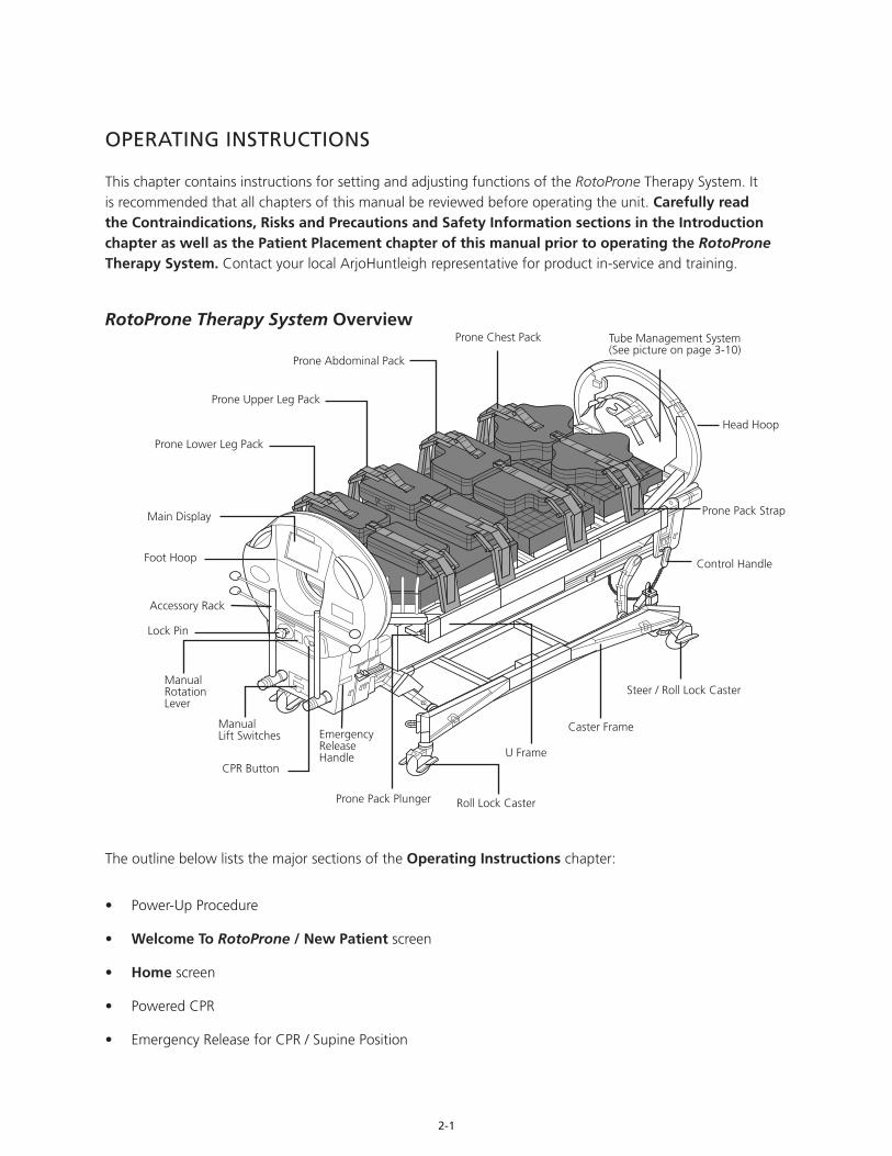
RotoProne Therapy System Overview
The outline below lists the major sections of the Operating Instructions chapter:
• Power-Up Procedure
• Welcome To RotoProne / New Patient screen
• Home screen
• Powered CPR
• Emergency Release for CPR / Supine Position
Prone Lower Leg Pack
Main Display
Foot Hoop
Accessory Rack
Lock Pin
Manual Rotation Lever
ManualLift Switches
Prone Pack Plunger
Emergency Release Handle
Roll Lock Caster
U Frame
Caster Frame
Steer / Roll Lock Caster
Control Handle
Prone Pack Strap
Head Hoop
Prone Chest Pack
Prone Abdominal Pack
Prone Upper Leg Pack
CPR Button
Tube Management System (See picture on page 3-10)
2-2
• Manual Rotation to Prone Instructions
• Help
• Hand Control
• Alarms
Power-Up Procedure
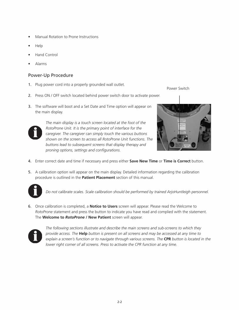
1. Plug power cord into a properly grounded wall outlet.
2. Press ON / OFF switch located behind power switch door to activate power.
3. The software will boot and a Set Date and Time option will appear on the main display.
The main display is a touch screen located at the foot of the RotoProne Unit. It is the primary point of interface for the caregiver. The caregiver can simply touch the various buttons shown on the screen to access all RotoProne Unit functions. The buttons lead to subsequent screens that display therapy and proning options, settings and configurations.
4. Enter correct date and time if necessary and press either Save New Time or Time is Correct button.
5. A calibration option will appear on the main display. Detailed information regarding the calibration procedure is outlined in the Patient Placement section of this manual.
Do not calibrate scales. Scale calibration should be performed by trained ArjoHuntleigh personnel.
6. Once calibration is completed, a Notice to Users screen will appear. Please read the Welcome to RotoProne statement and press the button to indicate you have read and complied with the statement. The Welcome to RotoProne / New Patient screen will appear.
The following sections illustrate and describe the main screens and sub-screens to which they provide access. The Help button is present on all screens and may be accessed at any time to explain a screen’s function or to navigate through various screens. The CPR button is located in the lower right corner of all screens. Press to activate the CPR function at any time.
1-844-557-7663
Power Switch

2-3
Welcome To RotoProne / New Patient Screen
Use the Welcome To RotoProne / New Patient screen to set up the RotoProne Unit for a new patient or to access former patient data.
• Press New Patient - Yes button to activate the RotoProne Set-up Wizard. The Set-up Wizard serves as a step-by-step guide to all screens required to prepare for a new patient.
• Press New Patient - No button to restore the data from most recently-placed patient on the unit.
Home Screen
The Home screen displays the current status of the RotoProne Therapy Unit. Readings on the Home screen show if the patient is in prone or supine position, how many degrees and to which direction the patient is rotated, how many degrees (if any) in Trendelenburg / Reverse Trendelenburg a patient is positioned and if the patient surface is rotating or paused. If the patient surface is not rotating, a message will be included on the Home screen to pull the lock pin to begin rotation.
Prolonged static positioning may increase risk of skin breakdown.
Use the Home screen to:
• Move the patient to prone or supine
• Access Kinetic Therapy and Prone Therapy settings
• Access scale functions
2-4
• Adjust patient surface position
• Park the patient (hold the patient surface at a desired angle)
• Access therapy meters
• Access Help
• Activate CPR
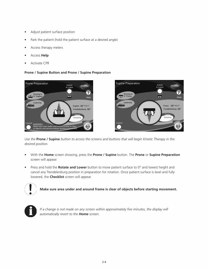
Prone / Supine Button and Prone / Supine Preparation
Use the Prone / Supine button to access the screens and buttons that will begin Kinetic Therapy in the desired position.
• With the Home screen showing, press the Prone / Supine button. The Prone or Supine Preparation screen will appear.
• Press and hold the Rotate and Lower button to move patient surface to 0° and lowest height and cancel any Trendelenburg position in preparation for rotation. Once patient surface is level and fully lowered, the Checklist screen will appear.
Make sure area under and around frame is clear of objects before starting movement.
If a change is not made on any screen within approximately five minutes, the display will automatically revert to the Home screen.
2-5
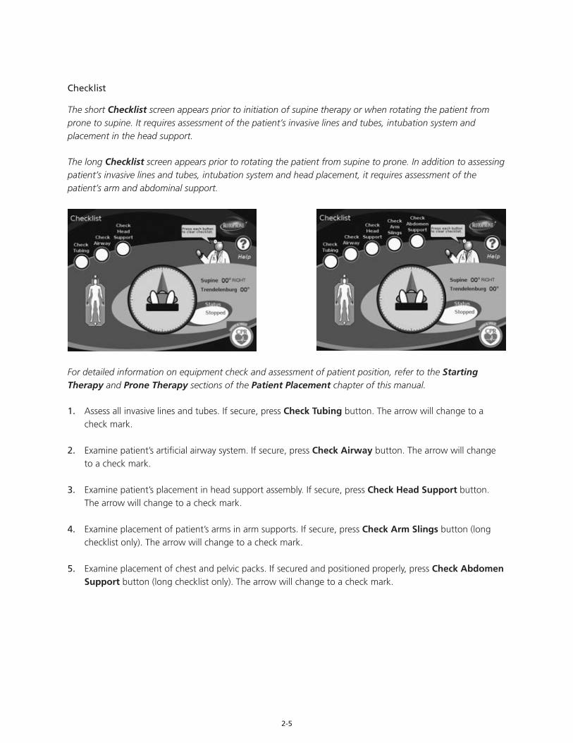
Checklist
The short Checklist screen appears prior to initiation of supine therapy or when rotating the patient from prone to supine. It requires assessment of the patient’s invasive lines and tubes, intubation system and placement in the head support.
The long Checklist screen appears prior to rotating the patient from supine to prone. In addition to assessing patient’s invasive lines and tubes, intubation system and head placement, it requires assessment of the patient’s arm and abdominal support.
For detailed information on equipment check and assessment of patient position, refer to the Starting Therapy and Prone Therapy sections of the Patient Placement chapter of this manual.
1. Assess all invasive lines and tubes. If secure, press Check Tubing button. The arrow will change to a check mark.
2. Examine patient’s artificial airway system. If secure, press Check Airway button. The arrow will change to a check mark.
3. Examine patient’s placement in head support assembly. If secure, press Check Head Support button. The arrow will change to a check mark.
4. Examine placement of patient’s arms in arm supports. If secure, press Check Arm Slings button (long checklist only). The arrow will change to a check mark.
5. Examine placement of chest and pelvic packs. If secured and positioned properly, press Check Abdomen Support button (long checklist only). The arrow will change to a check mark.
2-6
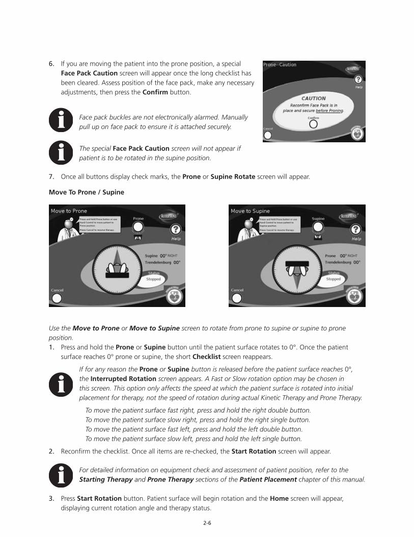
6. If you are moving the patient into the prone position, a special Face Pack Caution screen will appear once the long checklist has been cleared. Assess position of the face pack, make any necessary adjustments, then press the Confirm button.
Face pack buckles are not electronically alarmed. Manually pull up on face pack to ensure it is attached securely.
The special Face Pack Caution screen will not appear if patient is to be rotated in the supine position.
7. Once all buttons display check marks, the Prone or Supine Rotate screen will appear.
Move To Prone / Supine
Use the Move to Prone or Move to Supine screen to rotate from prone to supine or supine to prone position.1. Press and hold the Prone or Supine button until the patient surface rotates to 0°. Once the patient
surface reaches 0° prone or supine, the short Checklist screen reappears.
If for any reason the Prone or Supine button is released before the patient surface reaches 0°, the Interrupted Rotation screen appears. A Fast or Slow rotation option may be chosen in this screen. This option only affects the speed at which the patient surface is rotated into initial placement for therapy, not the speed of rotation during actual Kinetic Therapy and Prone Therapy.
To move the patient surface fast right, press and hold the right double button.To move the patient surface slow right, press and hold the right single button.To move the patient surface fast left, press and hold the left double button.To move the patient surface slow left, press and hold the left single button.
2. Reconfirm the checklist. Once all items are re-checked, the Start Rotation screen will appear.
For detailed information on equipment check and assessment of patient position, refer to the Starting Therapy and Prone Therapy sections of the Patient Placement chapter of this manual.
3. Press Start Rotation button. Patient surface will begin rotation and the Home screen will appear, displaying current rotation angle and therapy status.
2-7
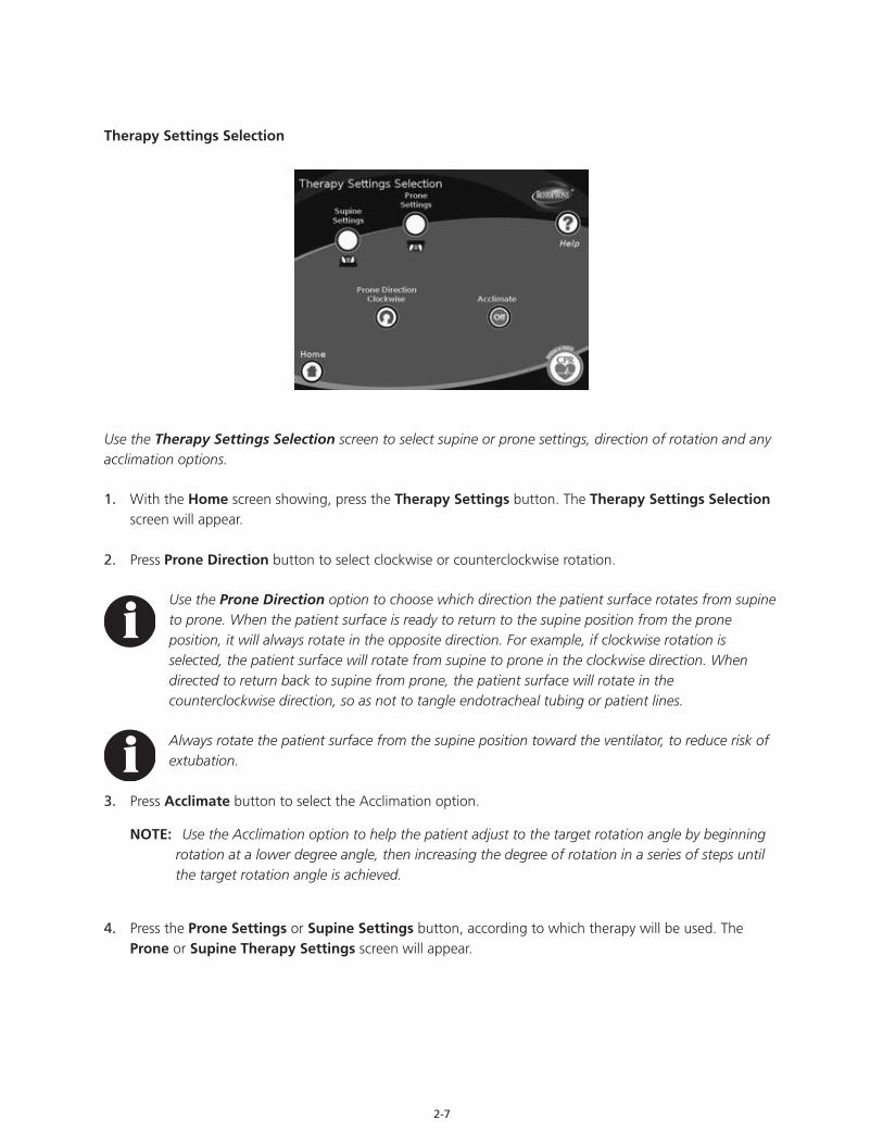
Therapy Settings Selection
Use the Therapy Settings Selection screen to select supine or prone settings, direction of rotation and any acclimation options.
1. With the Home screen showing, press the Therapy Settings button. The Therapy Settings Selection screen will appear.
2. Press Prone Direction button to select clockwise or counterclockwise rotation.
Use the Prone Direction option to choose which direction the patient surface rotates from supine to prone. When the patient surface is ready to return to the supine position from the prone position, it will always rotate in the opposite direction. For example, if clockwise rotation is selected, the patient surface will rotate from supine to prone in the clockwise direction. When directed to return back to supine from prone, the patient surface will rotate in the counterclockwise direction, so as not to tangle endotracheal tubing or patient lines.
Always rotate the patient surface from the supine position toward the ventilator, to reduce risk of extubation.
3. Press Acclimate button to select the Acclimation option.
NOTE: Use the Acclimation option to help the patient adjust to the target rotation angle by beginning rotation at a lower degree angle, then increasing the degree of rotation in a series of steps until the target rotation angle is achieved.
4. Press the Prone Settings or Supine Settings button, according to which therapy will be used. The Prone or Supine Therapy Settings screen will appear.

2-8
Use the Prone and Supine Therapy Settings screen to select and adjust left, center and right pause times and left and right rotation angles.
Therapy settings should be determined per physician’s orders.
1. Select the desired setting to change by pressing the corresponding button location; button will turn yellow when selected.
2. Press the Adjust up or down arrow button to reach the desired setting.
3. Press the Done button to save all settings and return to the Therapy Settings Selection screen.
4. Press the Home button to return to the Home screen.
Therapy Settings Definitions
• Patient Left Pause Time: The amount of time the patient is held in place once the target left rotation angle is reached. Minimum pause time is one minute; maximum pause time is 30 minutes.
• Patient Center Pause Time: The amount of time the patient is held in a level position after rotating to the right or left. Minimum pause time is zero; maximum pause time is 30 minutes.
• Patient Right Pause Time: The amount of time the patient is held in place once the target right rotation angle is reached. Minimum pause time is one minute; maximum pause time is 30 minutes.
• Patient Left Maximum Angle: The target left rotation angle to which the patient will turn during rotation and left pause.
• Patient Right Maximum Angle: The target right rotation angle to which the patient will turn during rotation and right pause.
Prone / Supine Settings
2-9
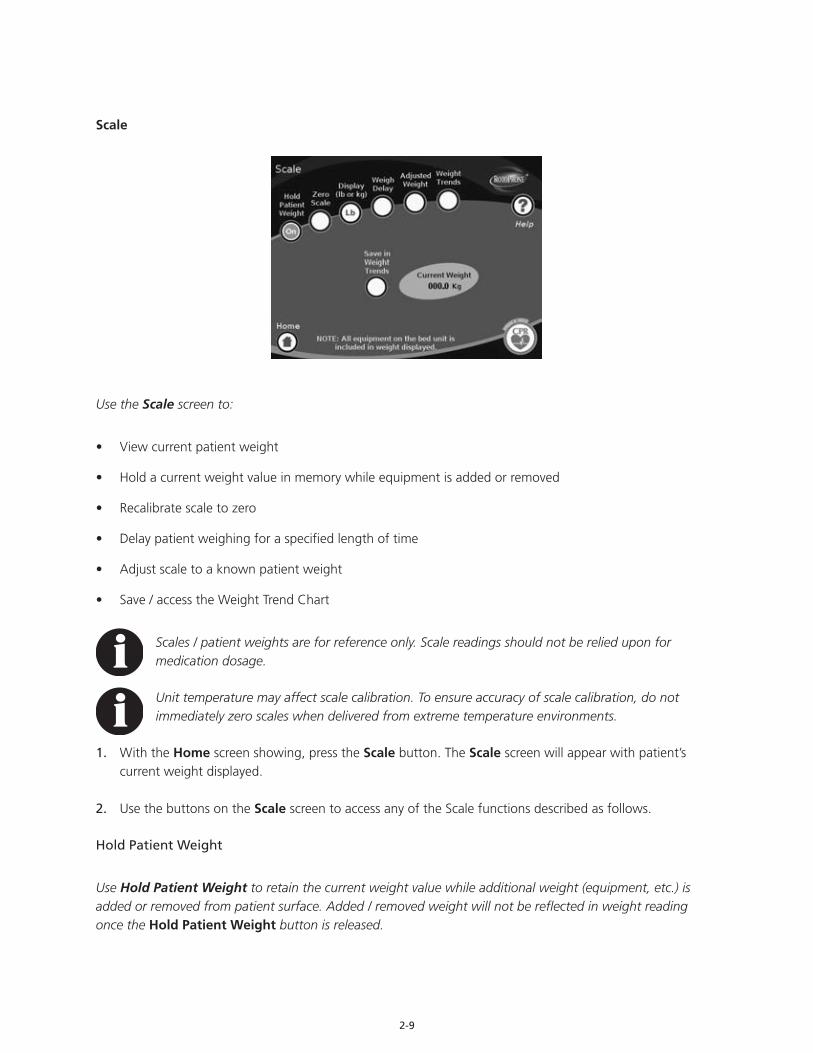
Scale Setting
Use the Scale screen to:
• View current patient weight
• Hold a current weight value in memory while equipment is added or removed
• Recalibrate scale to zero
• Delay patient weighing for a specified length of time
• Adjust scale to a known patient weight
• Save / access the Weight Trend Chart
Scales / patient weights are for reference only. Scale readings should not be relied upon for medication dosage.
Unit temperature may affect scale calibration. To ensure accuracy of scale calibration, do not immediately zero scales when delivered from extreme temperature environments.
1. With the Home screen showing, press the Scale button. The Scale screen will appear with patient’s current weight displayed.
2. Use the buttons on the Scale screen to access any of the Scale functions described as follows.
Hold Patient Weight
Use Hold Patient Weight to retain the current weight value while additional weight (equipment, etc.) is added or removed from patient surface. Added / removed weight will not be reflected in weight reading once the Hold Patient Weight button is released.

2-10
1. Press the Hold Patient Weight button; the button will change to green and the scale freezes.
2. Add or remove items from the patient surface; wait approximately five to ten seconds.
3. Press the Hold Patient Weight button again; the button will change to red and the scale resumes function with no change in weight.
Zero Scale
Use Zero to recalibrate the Scale to zero kilograms (or zero pounds) prior to patient placement, with any linens, equipment, etc. already placed on patient surface or frame.
• Press Zero button; a confirmation screen will appear.
• Press Yes button. A Zeroing Scales screen will appear. DO NOT TOUCH UNIT UNTIL SCREEN CHANGES. Current Weight display will change to zero and the Scale screen will reappear.
Display
Use Display to change the display to kilograms or pounds. Default scale display is in kilograms.
• Press the Display button; the Current Weight display will change from kilograms to pounds.
Weigh Delay
Use Weigh Delay to postpone weighing for a specified amount of time while tubes, equipment, etc. are lifted and then to hold the resulting weight value until it is read and recorded. Weigh Delay adds a weight reading to the Weight Trend Chart at the end of the specified time.
1. Press Weigh Delay button; Weigh Delay screen will appear.
2. Set desired delay time. Use the up and down arrow buttons to increase and decrease the weigh delay time.
3. Press Start button.
4. Add or remove items from patient surface.
5. As soon as countdown is complete, an alert beep will sound. The current weight is saved in Weight Trends and the scale resumes regular function.
6. Press Done button; Scale screen will reappear.

2-11
Adjusted Weight
Use Adjusted Weight to change the current weight display to a known weight. This function is most useful if the scale has not been zeroed before placing the patient.
1. Press Adjusted Weight button. Adjusted Weight screen will appear.
2. Press the up arrow button to increase the adjusted weight displayed.
3. Press the down arrow button to decrease the adjusted weight displayed.
4. When the desired weight is reached, press the Save button. The Scale screen will reappear with the adjusted weight in the Current Weight display.
5. When desired weight is saved, press the Done button. The Scale screen will reappear with the adjusted weight in the Current Weight display.
Weight Trends
Use Weight Trends to view the initial weight value and date of reading as well as the date, time and weight value of the four most recent weight readings.
1. Press the Weight Trends button. The Weight Trends screen will appear with the current weight displayed at the bottom of the chart.• A separate box at the top of the Weight Trend
Chart will display the date and initial weight entered during patient placement. This information is for reference and will not change.
• The most recent weight reading will appear on the bottom line of the display. This information will move up one line each time a new weight reading is saved into the Weight Trend Chart and will eventually move up and off the display.
2. Press the Save in Weight Trends button to enter the current weight into the Weight Trends Chart.
3. Use the up and down arrow buttons to move through and view previous weight readings.
4. Press Done to return to the Scale screen.

2-12
Surface Position
Use the Surface Position screen to adjust the height and angle of the patient surface. Maximum Trendelenburg and Reverse Trendelenburg angle is + / - 11°.
• With the Home screen showing, press the Surface Position button. The Surface Position screen will appear. Depending on patient status, the position displayed will either be prone or supine.
Make sure area under and around frame is clear of objects, persons and parts of body before starting movement.
Surface Height
1. Press and hold up arrow button to raise height of patient surface.
2. Press and hold down arrow button to lower height of patient surface.
Trendelenburg / Reverse Trendelenburg
1. Press and hold up arrow button for Trendelenburg. In prone position, the up arrow will simply level and lower the patient surface.
Trendelenburg angle is not available in the prone position.
2. Press and hold down arrow button for Reverse Trendelenburg.
2-13
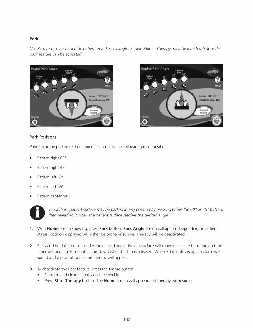
Park
Use Park to turn and hold the patient at a desired angle. Supine Kinetic Therapy must be initiated before the park feature can be activated.
Park Positions
Patient can be parked (either supine or prone) in the following preset positions:
• Patient right 60°
• Patient right 45°
• Patient left 60°
• Patient left 45°
• Patient center park
In addition, patient surface may be parked in any position by pressing either the 60° or 45° button, then releasing it when the patient surface reaches the desired angle.
1. With Home screen showing, press Park button. Park Angle screen will appear. Depending on patient status, position displayed will either be prone or supine. Therapy will be deactivated.
2. Press and hold the button under the desired angle. Patient surface will move to selected position and the timer will begin a 30-minute countdown when button is released. When 30 minutes is up, an alarm will sound and a prompt to resume therapy will appear.
3. To deactivate the Park feature, press the Home button.• Confirm and clear all items on the checklist.• Press Start Therapy button. The Home screen will appear and therapy will resume.

2-14
Therapy Meters
Use the Therapy Meters screen to:
• View daily and cumulative Kinetic Therapy time greater than or equal to 40° of rotation in both prone and supine positions.
• View total daily and cumulative Kinetic Therapy time in both prone and supine positions.
• Access a particular date for therapy to be displayed.
• Access the Therapy Chart.
1. With the Home screen showing, press the Therapy Meters button. The Therapy Meters screen will appear.• Total accumulated therapy time from initial patient
placement and unit power up is displayed in the Total Time section of the screen.
• Therapy time for the current date is displayed in the Today line of the Therapy Chart. Therapy time is broken down into following categories: - Time spent that day at greater than or equal to
40° in the prone position. - Total time spent that day in the prone position. - Time spent that day at greater than or equal to
40° in the supine position. - Total time spent that day in the supine position.
• Therapy time for the entire time the patient has been on the unit is displayed in the Cumulative line of the Therapy Chart. Therapy time is broken down into following categories: - Time spent since patient placement at greater than or equal to 40° in the prone position. - Total time spent since patient placement in the prone position. - Time spent since patient placement at greater than or equal to 40° in the supine position. - Total time spent since patient placement in the supine position.
2. Press the up and down arrow buttons in the Change Date section of the screen to search for a specific date. The therapy time for the chosen date will be displayed in the Today line of the Therapy Chart.
3. Press Therapy Chart button to access the Therapy Chart.
4. Press Home button to return to Home screen.
2-15
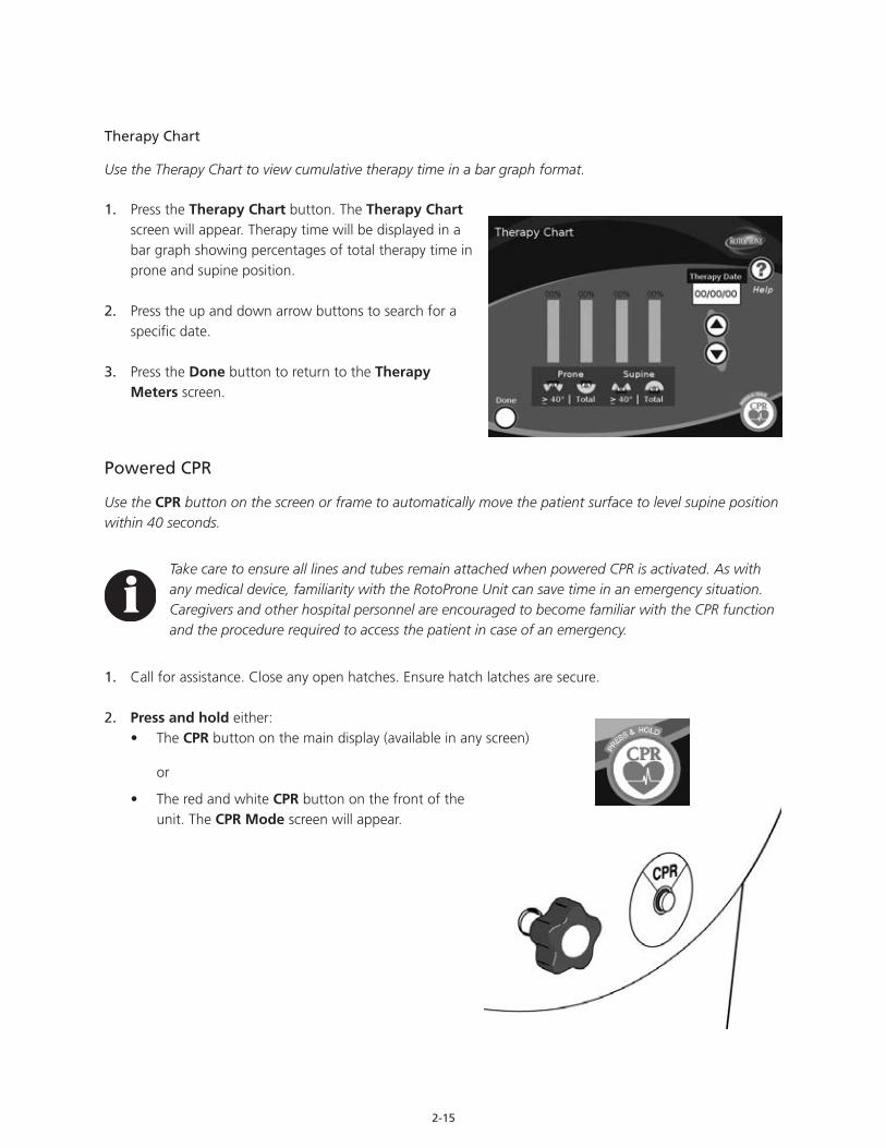
Therapy Chart
Use the Therapy Chart to view cumulative therapy time in a bar graph format.
1. Press the Therapy Chart button. The Therapy Chart screen will appear. Therapy time will be displayed in a bar graph showing percentages of total therapy time in prone and supine position.
2. Press the up and down arrow buttons to search for a specific date.
3. Press the Done button to return to the Therapy Meters screen.
Powered CPR
Use the CPR button on the screen or frame to automatically move the patient surface to level supine position within 40 seconds.
Take care to ensure all lines and tubes remain attached when powered CPR is activated. As with any medical device, familiarity with the RotoProne Unit can save time in an emergency situation. Caregivers and other hospital personnel are encouraged to become familiar with the CPR function and the procedure required to access the patient in case of an emergency.
1. Call for assistance. Close any open hatches. Ensure hatch latches are secure.
2. Press and hold either:• The CPR button on the main display (available in any screen)
or
• The red and white CPR button on the front of the unit. The CPR Mode screen will appear.

2-16
• Continue pressing either button until patient surface is leveled, fully lowered and rotated into the 0° supine position.
Bed will stop at 67° if unsafe operating condition occurs.
• Once patient surface has reached 0° supine, the CPR Information screen will appear.
3. Push in lock pin to secure surface.
Ensure lock pin is fully engaged.
4. Unbuckle and stow chest pack.
5. Begin CPR as quickly as possible.
6. Unbuckle and stow remaining proning packs, as necessary.
7. Unfasten abdominal sling and fold to one side.
8. Remove the following, if necessary:• Arms from arm sling• Side support packs and accessory packs• Face pack
9. Place backboard under patient, following institution protocols and universal precautions.
10. After CPR is performed and patient is clinically stable, follow all applicable steps for securing patient and reengaging therapy.
2-17
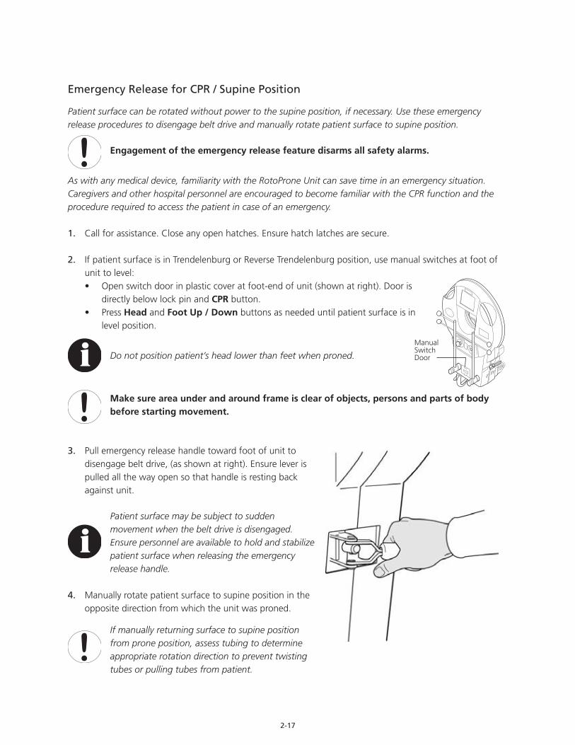
Emergency Release for CPR / Supine Position
Patient surface can be rotated without power to the supine position, if necessary. Use these emergency release procedures to disengage belt drive and manually rotate patient surface to supine position.
Engagement of the emergency release feature disarms all safety alarms.
As with any medical device, familiarity with the RotoProne Unit can save time in an emergency situation. Caregivers and other hospital personnel are encouraged to become familiar with the CPR function and the procedure required to access the patient in case of an emergency.
1. Call for assistance. Close any open hatches. Ensure hatch latches are secure.
2. If patient surface is in Trendelenburg or Reverse Trendelenburg position, use manual switches at foot of unit to level:• Open switch door in plastic cover at foot-end of unit (shown at right). Door is
directly below lock pin and CPR button.• Press Head and Foot Up / Down buttons as needed until patient surface is in
level position.
Do not position patient’s head lower than feet when proned.
Make sure area under and around frame is clear of objects, persons and parts of body before starting movement.
3. Pull emergency release handle toward foot of unit to disengage belt drive, (as shown at right). Ensure lever is pulled all the way open so that handle is resting back against unit.
Patient surface may be subject to sudden movement when the belt drive is disengaged. Ensure personnel are available to hold and stabilize patient surface when releasing the emergency release handle.
4. Manually rotate patient surface to supine position in the opposite direction from which the unit was proned.
If manually returning surface to supine position from prone position, assess tubing to determine appropriate rotation direction to prevent twisting tubes or pulling tubes from patient.
Manual Switch Door
2-18
5. Once patient surface has reached 0° supine:• Push in lock pin to stabilize patient surface. Ensure lock pin is fully engaged.• Re-engage emergency release handle to secure patient surface.
6. Unbuckle and stow chest pack.
7. Begin CPR as quickly as possible.
8. Unbuckle and stow remaining proning packs, as necessary.
9. Unfasten abdominal sling and fold to one side.
10. Remove the following, if necessary:• Arms from arm sling• Side support packs and accessory packs• Face pack
11. Place backboard under patient, following institution protocols and universal precautions.
12. After CPR is performed and patient is clinically stable, follow all applicable steps for securing patient and reengaging therapy.
In case of stuck or jammed lock pin, refer to the trouble shooting section for stuck or jammed lock pin instructions, page 2-27.
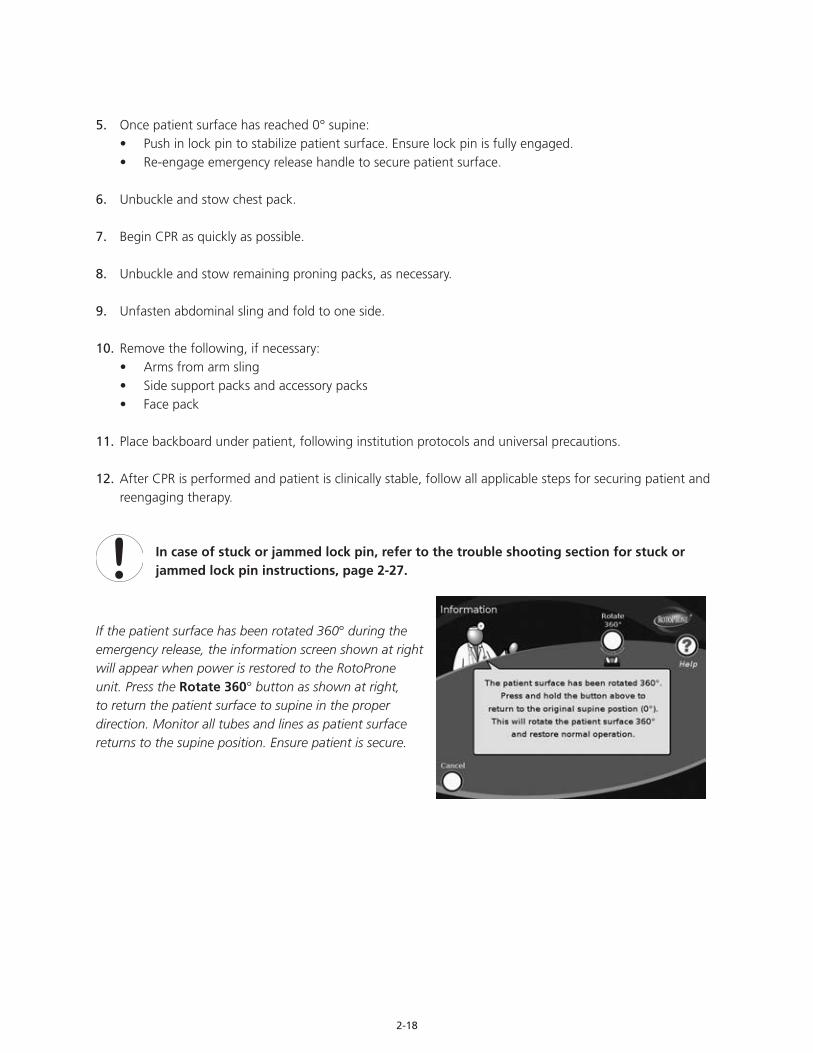
If the patient surface has been rotated 360° during the emergency release, the information screen shown at right will appear when power is restored to the RotoProne unit. Press the Rotate 360° button as shown at right, to return the patient surface to supine in the proper direction. Monitor all tubes and lines as patient surface returns to the supine position. Ensure patient is secure.

2-19
Manual Rotation to Prone Instructions
Patient surface can be rotated without power to the prone position, if necessary. Use these emergency release procedures to manually rotate the patient surface to prone position.
• At least three people recommended for task• Patient must start at 0˚ supine • Lock Pin must be pulled out
In case of stuck or jammed lock pin, refer to the trouble shooting section for stuck or jammed lock pin instructions, page 2-27.
If patient is NOT 0˚ supine:
1. Instruct person 2 and 3 to secure frame at head-end and provide notification when frame is secure.
2. Disengage Emergency Release Handle.
Unit may shift when Emergency Release Handle is disengaged.
3. Instruct person 2 and 3 to rotate patient to 0˚ supine.
When patient is 0˚ supine:
1. Determine proper direction for rotation.
2. Instruct person 2 and 3 to secure patient (including buckles and hatches) for proning and monitor all tubes and lines.
3. Disengage emergency release handle,if necessary.
4. Break tab to open door and access manual rotation lever.
5. Lift and hold manual rotation lever for duration of manual rotation.
Audible notification will sound while manual rotation lever is active.
6. Instruct person 2 and 3 to rotate patient to prone position.
7. Release manual rotation lever and re-engage emergency release handle. Call ArjoHuntleigh at 1-844-557-7663.
3 2
1Emergency Release Handle
Manual RotationLever
2-20
Help
Online help information may be accessed from any screen by pressing the Help button. Online help for each screen will include a description of screen functions and step-by-step instructions on how to use each of them.
Hand Control
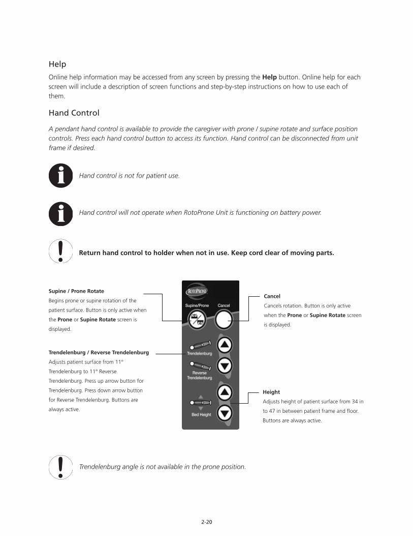
A pendant hand control is available to provide the caregiver with prone / supine rotate and surface position controls. Press each hand control button to access its function. Hand control can be disconnected from unit frame if desired.
Hand control is not for patient use.
Hand control will not operate when RotoProne Unit is functioning on battery power.
Return hand control to holder when not in use. Keep cord clear of moving parts.
Trendelenburg angle is not available in the prone position.
Cancel
Cancels rotation. Button is only active
when the Prone or Supine Rotate screen
is displayed.
Supine / Prone Rotate
Begins prone or supine rotation of the
patient surface. Button is only active when
the Prone or Supine Rotate screen is
displayed.
Height
Adjusts height of patient surface from 34 in
to 47 in between patient frame and floor.
Buttons are always active.
Trendelenburg / Reverse Trendelenburg
Adjusts patient surface from 11°
Trendelenburg to 11° Reverse
Trendelenburg. Press up arrow button for
Trendelenburg. Press down arrow button
for Reverse Trendelenburg. Buttons are
always active.
2-21
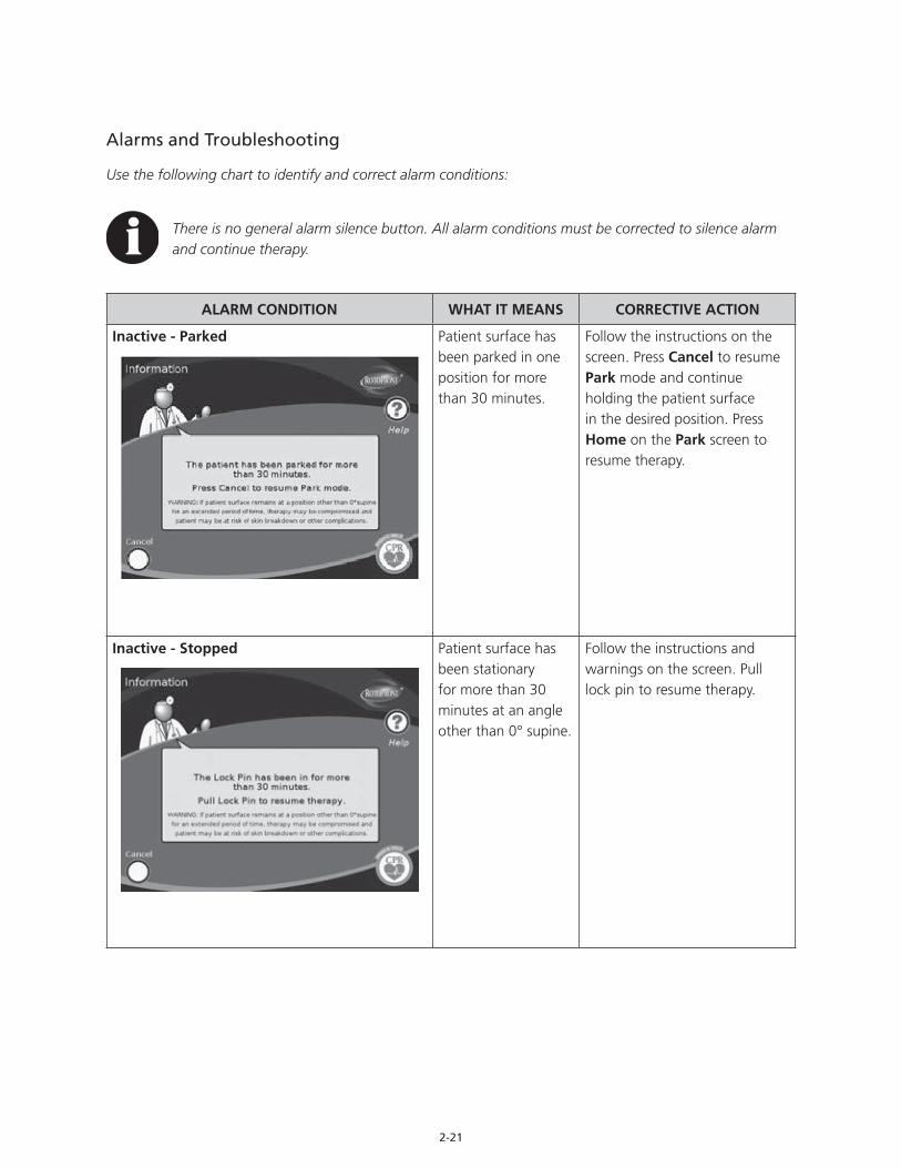
Alarms and Troubleshooting
Use the following chart to identify and correct alarm conditions:
There is no general alarm silence button. All alarm conditions must be corrected to silence alarm and continue therapy.
ALARM CONDITION WHAT IT MEANS CORRECTIVE ACTION
Inactive - Parked Patient surface has been parked in one position for more than 30 minutes.
Follow the instructions on the screen. Press Cancel to resume Park mode and continue holding the patient surface in the desired position. Press Home on the Park screen to resume therapy.
Inactive - Stopped Patient surface has been stationary for more than 30 minutes at an angle other than 0° supine.
Follow the instructions and warnings on the screen. Pull lock pin to resume therapy.
2-22
ALARM CONDITION WHAT IT MEANS CORRECTIVE ACTION
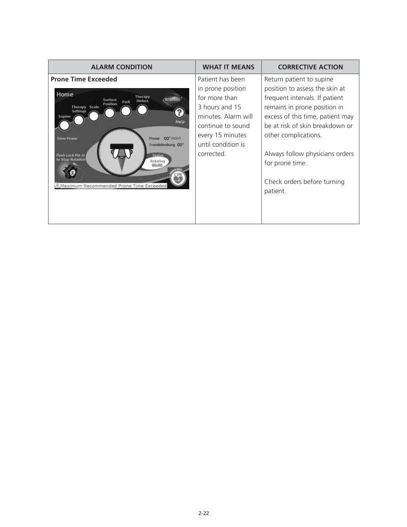
Prone Time Exceeded Patient has been in prone position for more than 3 hours and 15 minutes. Alarm will continue to sound every 15 minutes until condition is corrected.
Return patient to supine position to assess the skin at frequent intervals. If patient remains in prone position in excess of this time, patient may be at risk of skin breakdown or other complications.
Always follow physicians orders for prone time.
Check orders before turning patient.
2-23
ALARM CONDITION WHAT IT MEANS CORRECTIVE ACTION
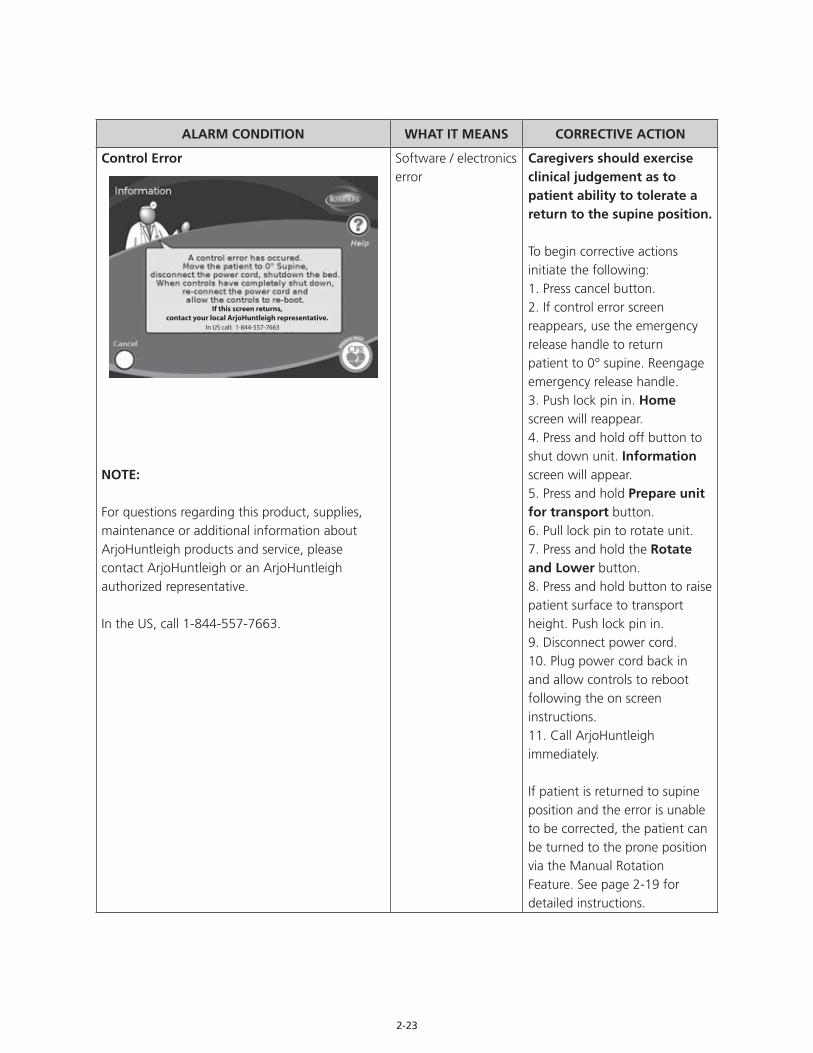
Control Error
NOTE:
For questions regarding this product, supplies, maintenance or additional information about ArjoHuntleigh products and service, please contact ArjoHuntleigh or an ArjoHuntleigh authorized representative.
In the US, call 1-844-557-7663.
Software / electronics error
Caregivers should exercise clinical judgement as to patient ability to tolerate a return to the supine position.
To begin corrective actions initiate the following:1. Press cancel button.2. If control error screen reappears, use the emergency release handle to return patient to 0° supine. Reengage emergency release handle.3. Push lock pin in. Home screen will reappear. 4. Press and hold off button to shut down unit. Information screen will appear.5. Press and hold Prepare unit for transport button.6. Pull lock pin to rotate unit.7. Press and hold the Rotate and Lower button.8. Press and hold button to raise patient surface to transport height. Push lock pin in.9. Disconnect power cord.10. Plug power cord back in and allow controls to reboot following the on screen instructions.11. Call ArjoHuntleigh immediately.
If patient is returned to supine position and the error is unable to be corrected, the patient can be turned to the prone position via the Manual Rotation Feature. See page 2-19 for detailed instructions.
In US call: 1-844-557-7663
If this screen returns,contact your local ArjoHuntleigh representative.

2-24
ALARM CONDITION WHAT IT MEANS CORRECTIVE ACTION
360 Error The patient surface has been rotated 360° from original zero supine position. This condition can only occur if patient surface has been manually rotated with the emergency release handle. Unit will not allow rotation over 360° in during powered operation.
Follow the instructions on the screen. Patient surface must be rotated back 360° to original zero supine position. Carefully monitor patient’s lines and tubes during this full rotation cycle.
Obstruction - Rotation There is a possible obstruction in the way of the patient surface.
Follow the instructions on the screen. Use the manual switches located behind the small door at the foot of the unit to raise the patient surface off the obstruction. Check for and remove any obstructions. Press Cancel button to resume rotation.
Obstruction error can occur if someone or something is leaning or standing on the frame.
2-25
ALARM CONDITION WHAT IT MEANS CORRECTIVE ACTION
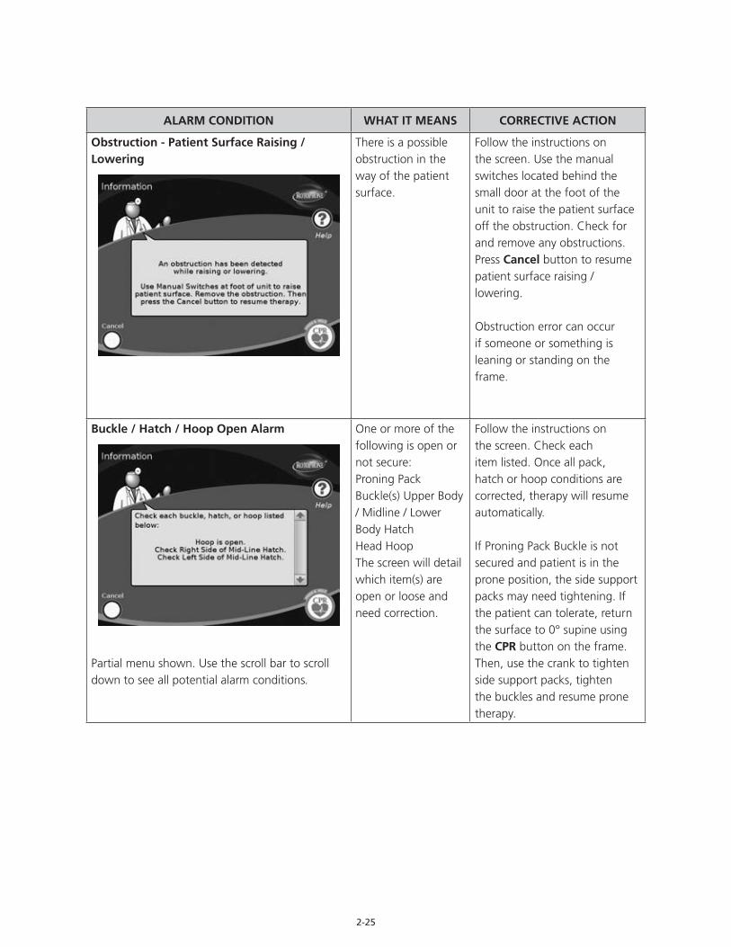
Obstruction - Patient Surface Raising / Lowering
There is a possible obstruction in the way of the patient surface.
Follow the instructions on the screen. Use the manual switches located behind the small door at the foot of the unit to raise the patient surface off the obstruction. Check for and remove any obstructions. Press Cancel button to resume patient surface raising / lowering.
Obstruction error can occur if someone or something is leaning or standing on the frame.
Buckle / Hatch / Hoop Open Alarm
Partial menu shown. Use the scroll bar to scroll down to see all potential alarm conditions.
One or more of the following is open or not secure: Proning Pack Buckle(s) Upper Body / Midline / Lower Body Hatch Head Hoop The screen will detail which item(s) are open or loose and need correction.
Follow the instructions on the screen. Check each item listed. Once all pack, hatch or hoop conditions are corrected, therapy will resume automatically.
If Proning Pack Buckle is not secured and patient is in the prone position, the side support packs may need tightening. If the patient can tolerate, return the surface to 0° supine using the CPR button on the frame. Then, use the crank to tighten side support packs, tighten the buckles and resume prone therapy.
2-26
ALARM CONDITION WHAT IT MEANS CORRECTIVE ACTION
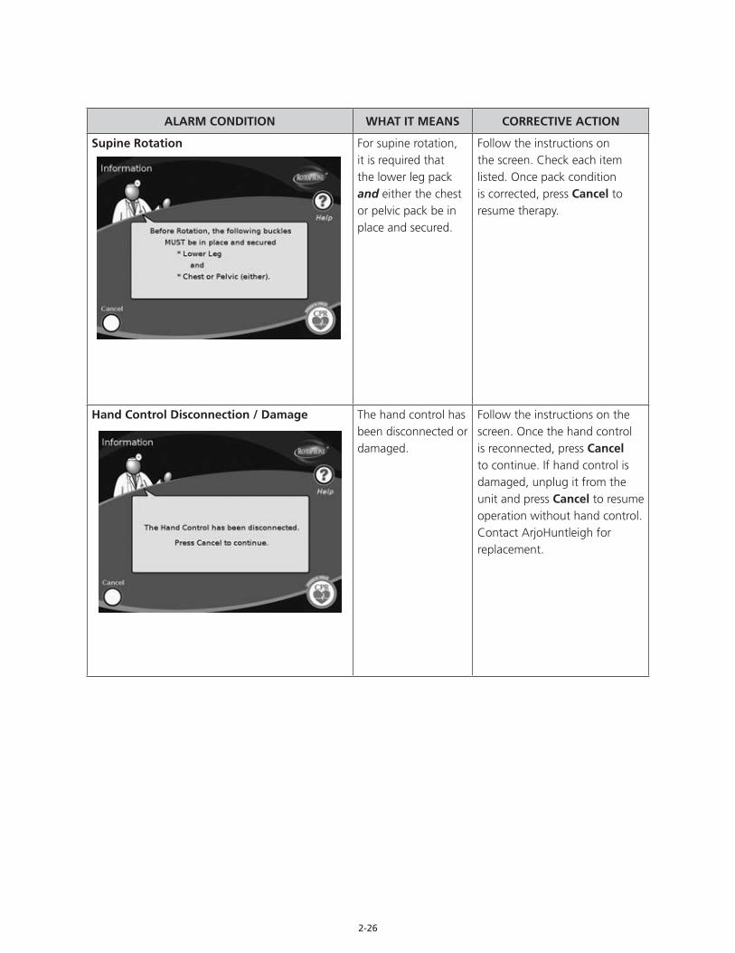
Supine Rotation For supine rotation, it is required that the lower leg pack and either the chest or pelvic pack be in place and secured.
Follow the instructions on the screen. Check each item listed. Once pack condition is corrected, press Cancel to resume therapy.
Hand Control Disconnection / Damage The hand control has been disconnected or damaged.
Follow the instructions on the screen. Once the hand control is reconnected, press Cancel to continue. If hand control is damaged, unplug it from the unit and press Cancel to resume operation without hand control. Contact ArjoHuntleigh for replacement.
2-27
ALARM CONDITION WHAT IT MEANS CORRECTIVE ACTION
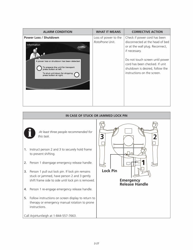
Power Loss / Shutdown Loss of power to the RotoProne Unit.
Check if power cord has been disconnected at the head of bed or at the wall plug. Reconnect, if necessary.
Do not touch screen until power cord has been checked. If unit shutdown is desired, follow the instructions on the screen.
IN CASE OF STUCK OR JAMMED LOCK PIN
At least three people recommended for this task.
1. Instruct person 2 and 3 to securely hold frame to prevent shifting.
2. Person 1 disengage emergency release handle.
3. Person 1 pull out lock pin. If lock pin remains stuck or jammed, have person 2 and 3 gently shift frame side to side until lock pin is removed.
4. Person 1 re-engage emergency release handle.
5. Follow instructions on screen display to return to therapy or emergency manual rotation to prone instructions.
Call ArjoHuntleigh at 1-844-557-7663.
3 2
1Lock Pin
EmergencyRelease Handle

2-28

3-1
PATIENT PLACEMENT
It is recommended that all chapters of this manual be reviewed prior to product use. Carefully read the Contraindications, Risks and Precautions and Safety Information sections in the Introduction chapter of this manual prior to placing a patient on the RotoProne Therapy System.
Preparation for Patient Placement
1. Lock caster brakes by pressing red pedal on each caster until clicked in place.
2. Configure patient surface, as required (add all packs, accessories, equipment to unit).
Any equipment on the unit frame is included in the weight displayed. Packs and all equipment (i.e. Foley bags) must be present on the patient surface to ensure accurate scale calibration.
3. Verify the following:• Ensure patient surface is at 0° supine position.• Ensure lock pin is engaged.
4. Plug power cord into a properly grounded wall outlet to activate power to the RotoProne Unit. Press on / off switch. The software will boot and the Set Date / Time screen will appear on the main display.
Do not use a wall outlet controlled by a wall switch.
• Press up and down arrows to set a new date and time.
• Press 24 Hour Time button to change time to 24-hour format, if desired.
• Press Save New Time button to continue.
or
• Press Time is Correct button to continue without saving a new date and time.
• The Calibration screen will appear.

3-2
5. Press both manual switches to raise unit to highest position. Manual switches are located on lower foot-end of unit frame, as shown at right.
6. Remove shipping blocks:• Remove foot-end shipping block:
- Pull pin from top of block. - Rotate block 90° toward caster frame. - Insert pin into top of block to lock block in place.
• Remove head-end transport block: - Pull pin from top of block. - Slide block toward head end of unit. - Rotate block 180°. - Insert pin into top of block to lock block in place.
7. Press Yes button. The RotoProne Calibration Utility screen will appear.
The No button may be pressed to skip calibration and continue directly to the Welcome To RotoProne / New Patient screen. However, it is recommended that calibration be performed any time the RotoProne Unit is powered up after transport, especially if it has traveled significant distance or over door thresholds. Do not calibrate scales. Scale calibration should be performed by trained ArjoHuntleigh personnel.
8. Press Start Calibration button. Unit calibration will begin.• Patient surface will raise to maximum height, move to a slight Trendelenberg angle and lower back
down.• Once patient surface has stopped moving, calibration status indicator will change to a green
calibrated indicator and calibration is complete.
Unit temperature may affect scale calibration. To ensure accuracy of scale calibration, do not immediately zero scales when delivered from extreme temperature environments.
Manual Switch Door
Calibrate Scales

3-3
9. Press Done button. The software will boot and the Notice To Users screen will appear.
10. Read through welcome information, then press round button at bottom of screen. The Welcome To RotoProne / New Patient? screen will appear.
11. Press Yes button. A confirmation screen will appear.
If the No button is selected, any previously saved patient information and therapy settings will be restored and the Main Menu screen will be displayed.
12. Press Yes button. The Are You Sure screen will appear and will ask if you want to clear the last patient’s data. Press the Yes or No button at bottom of screen.
13. Press Yes button. The Set Up Wizard screen will appear.
The Set Up Wizard guides the user through all screen displays necessary to place a new patient and begin therapy.
Pressing Done button starts the collection of new patient data without using the Set-Up Wizard. If Done button is pressed, the Home screen will appear, default settings will be used for therapy, and the scale must be zeroed manually.
If you are unable to locate the Operations Manual, have not receivedproduct inservice, or have specific product questions, please contactyour local ArjoHuntleigh representative.
3-4
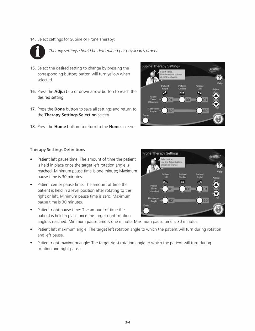
14. Select settings for Supine or Prone Therapy:
Therapy settings should be determined per physician’s orders.
15. Select the desired setting to change by pressing the corresponding button; button will turn yellow when selected.
16. Press the Adjust up or down arrow button to reach the desired setting.
17. Press the Done button to save all settings and return to the Therapy Settings Selection screen.
18. Press the Home button to return to the Home screen.
Therapy Settings Definitions
• Patient left pause time: The amount of time the patient is held in place once the target left rotation angle is reached. Minimum pause time is one minute; Maximum pause time is 30 minutes.
• Patient center pause time: The amount of time the patient is held in a level position after rotating to the right or left. Minimum pause time is zero; Maximum pause time is 30 minutes.
• Patient right pause time: The amount of time the patient is held in place once the target right rotation angle is reached. Minimum pause time is one minute; Maximum pause time is 30 minutes.
• Patient left maximum angle: The target left rotation angle to which the patient will turn during rotation and left pause.
• Patient right maximum angle: The target right rotation angle to which the patient will turn during rotation and right pause.

3-5
19. Select desired therapy options:• Press Prone Direction button to select clockwise
or counterclockwise rotation from supine to prone.
The Prone Direction option determines which direction the patient surface rotates from supine to prone. When the patient surface is ready to return to the supine position from the prone position, it will always rotate back in the opposite direction. For example, if clockwise rotation is selected, the patient surface will rotate from supine to prone in the clockwise direction. When directed to return back to supine from prone, the patient surface will rotate in the counterclockwise direction, so as not to tangle endotracheal tubing or patient lines. Place vent tubing centered on tube management system or opposite side from the vent in supine position.
Always rotate the patient surface from the supine position toward the ventilator, to reduce risk of extubation.
• Press Acclimate button to select the Acclimation option.
Use the Acclimation option to help the patient adjust to the target rotation angle by beginning rotation at a lower degree angle, then increasing the degree of rotation in a series of steps until the target rotation angle is achieved.
• Press Next button. The Scale screen will appear.
20. Set scale to zero:
Any equipment on the unit frame is included in the weight displayed. Packs and all equipment (linens, lift pads, heating / cooling blankets etc.) must be present on the patient surface to ensure accurate scale calibration.
Scales / patient weights are for reference only. scale readings should not be relied upon for medication dosage.
• Press the Zero button. A confirmation screen will appear.• Press the Yes button. Current Weight reading will change to 0.000.• Press the Display button to select Lb or Kg display option (default is Kg).
3-6
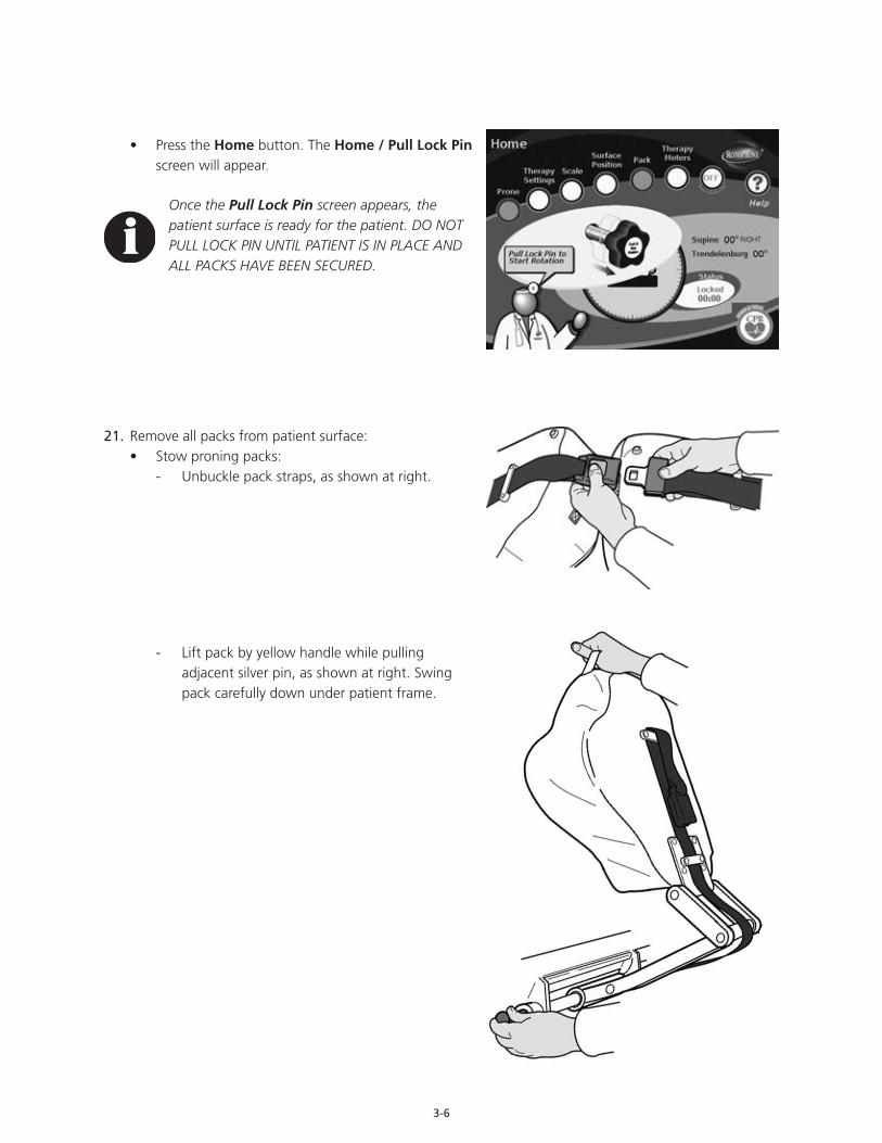
• Press the Home button. The Home / Pull Lock Pin screen will appear.
Once the Pull Lock Pin screen appears, the patient surface is ready for the patient. DO NOT PULL LOCK PIN UNTIL PATIENT IS IN PLACE AND ALL PACKS HAVE BEEN SECURED.
21. Remove all packs from patient surface:• Stow proning packs:
- Unbuckle pack straps, as shown at right.
- Lift pack by yellow handle while pulling adjacent silver pin, as shown at right. Swing pack carefully down under patient frame.

3-7
Pack will release once pin is pulled. Be sure pack is well-supported.
- Hold pack and fasten yellow strap, as shown at right.
- Push pack up until locked, as shown at right. There will be an audible click when pack locks into place.
If pack does not lock, manually push pin in while pushing pack up.
• Remove leg abductor pack: - Pull knob / plunger on post bracket pins to clear
post bracket receptacles. - Lift pack from patient surface using handle. - Place pack on a clean surface. DO NOT PLACE
PACK ON FLOOR.
3-8
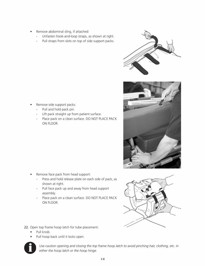
• Remove abdominal sling, if attached:, if attached
- Unfasten hook-and-loop straps, as shown at right. - Pull straps from slots on top of side support packs.
• Remove side support packs: - Pull and hold pack pin. - Lift pack straight up from patient surface. - Place pack on a clean surface. DO NOT PLACE PACK
ON FLOOR.
• Remove face pack from head support: - Press and hold release plate on each side of pack, as
shown at right. - Pull face pack up and away from head support
assembly. - Place pack on a clean surface. DO NOT PLACE PACK
ON FLOOR.
22. Open top frame hoop latch for tube placement:• Pull knob.• Pull hoop back until it locks open.
Use caution opening and closing the top frame hoop latch to avoid pinching hair, clothing, etc. in either the hoop latch or the hoop hinge.
3-9
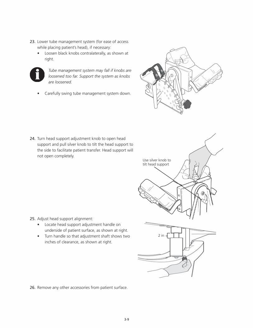
23. Lower tube management system (for ease of access while placing patient’s head), if necessary:• Loosen black knobs contralaterally, as shown at
right.
Tube management system may fall if knobs are loosened too far. Support the system as knobs are loosened.
• Carefully swing tube management system down.
24. Turn head support adjustment knob to open head support and pull silver knob to tilt the head support to the side to facilitate patient transfer. Head support will not open completely.
25. Adjust head support alignment:• Locate head support adjustment handle on
underside of patient surface, as shown at right.• Turn handle so that adjustment shaft shows two
inches of clearance, as shown at right.
26. Remove any other accessories from patient surface.
2 in
Use silver knob to tilt head support
3-10
Patient Transfer to the RotoProne Therapy System
Do not leave patient unattended at any time during patient transfer process.
Perform transfer from the patient left side onto RotoProne Unit when possible. This will allow for line placement through the open side of the top frame hoop, into the tube management system.
1. Use hand control or surface position screen to adjust height of patient surface to same level as surface from which patient is being transferred.
2. Ensure all four caster brakes on both surfaces are locked.
3. Cover brackets and block for leg abductor and side support packs with washcloth or similar padding on side of patient surface across which the patient will be transferred. Washcloths will pad the brackets and help ensure patient comfort during transfer.
4. Transfer patient to the RotoProne patient support surface following all applicable safety rules and institution protocols.
5. Raise tube management system:• Swing tube management system up and hold in place.• Tighten black knobs contralaterally on each side.
Ensure the tube management system is secure and does not swing back down into the unit frame. Ensure that tubes and lines do not catch or become tangled.
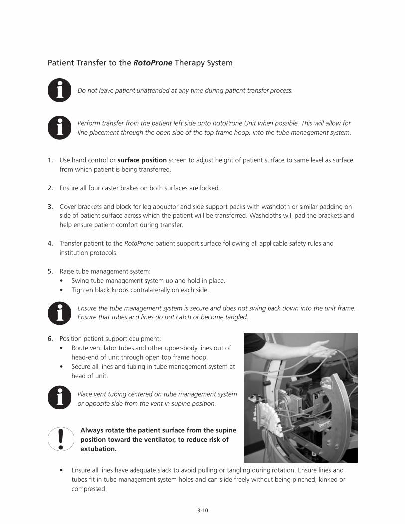
6. Position patient support equipment:• Route ventilator tubes and other upper-body lines out of
head-end of unit through open top frame hoop.• Secure all lines and tubing in tube management system at
head of unit.
Place vent tubing centered on tube management system or opposite side from the vent in supine position.
Always rotate the patient surface from the supine position toward the ventilator, to reduce risk of extubation.
• Ensure all lines have adequate slack to avoid pulling or tangling during rotation. Ensure lines and tubes fit in tube management system holes and can slide freely without being pinched, kinked or compressed.

3-11
IV extension tubing is recommended to allow for adequate slack.
7. Position patient on RotoProne surface:• Place patient’s head on main pack within head support.• Ensure that the head support assembly is pulled all the way toward the head of the unit.
Use extra care when placing patients with intracranial monitoring or drainage devices (e.g., cranial bolt or ventriculostomy). Consider discontinuing placement if patient’s head cannot be properly secured with intracranial monitoring / drainage device in place.
• Align patient’s ears with openings in the sides of head support, as shown at right.
It is very important that the patient’s ears remain aligned with the openings in the head support. Proper positioning and alignment of the head and ears determines optimum support for the patient’s head. Check head position often during the remainder of the patient placement procedure, especially when all other packs are positioned and tightened.
8. Center patient from side to side on patient surface.
9. Secure patient’s hair (if needed) or other parts of the body away from moving parts (roller and head support hinges).
Keep all equipment, tubes and lines, loose clothing, hair and other parts of the body away from moving parts and pinch points.
10. Turn head support adjustment knob to close head support around patient’s head. Head support packs should lightly touch sides of patient’s head without compressing the pack foam or puckering patient’s skin.
Fitting the Head Support, Face Pack or other packs too tightly may increase pressure points, possibly leading to skin breakdown. Assess skin at frequent intervals depending on patient condition (at least every 4 hours). Give extra attention to skin at pressure points and locations where moisture or incontinence may occur or collect. Common pressure points include, but are not limited to, the face, ears, axilla, shoulders, sides and upper and lower extremities. Early intervention may be critical to preventing serious skin breakdown.
3-12
Pack InstallationSide support packs and all proning packs (chest, pelvic, upper leg and lower leg) are REQUIRED for prone positioning. In addition, the face pack is required if using prone therapy. For supine rotation, the lower leg proning packs and either the chest or pelvic proning packs are required.
Leg Abductor Pack
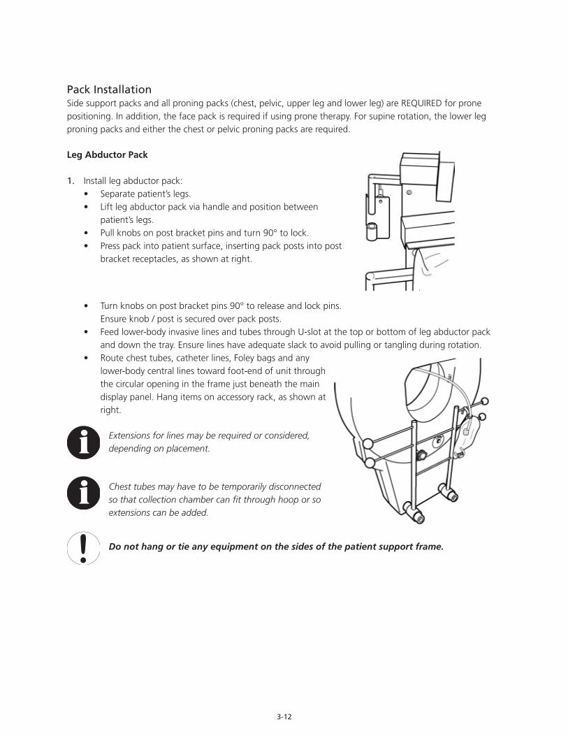
1. Install leg abductor pack:• Separate patient’s legs.• Lift leg abductor pack via handle and position between
patient’s legs.• Pull knobs on post bracket pins and turn 90° to lock.• Press pack into patient surface, inserting pack posts into post
bracket receptacles, as shown at right.
• Turn knobs on post bracket pins 90° to release and lock pins. Ensure knob / post is secured over pack posts.
• Feed lower-body invasive lines and tubes through U-slot at the top or bottom of leg abductor pack and down the tray. Ensure lines have adequate slack to avoid pulling or tangling during rotation.
• Route chest tubes, catheter lines, Foley bags and any lower-body central lines toward foot-end of unit through the circular opening in the frame just beneath the main display panel. Hang items on accessory rack, as shown at right.
Extensions for lines may be required or considered, depending on placement.
Chest tubes may have to be temporarily disconnected so that collection chamber can fit through hoop or so extensions can be added.
Do not hang or tie any equipment on the sides of the patient support frame.
3-13
2. Adjust foot support boards to provide proper foot positioning and help prevent foot drop.
The RotoProne Therapy System will accommodate patients up to approximately 6 ft 2 in tall with the foot support boards in their lowest position.
• Determine appropriate position for patient’s foot.• Pull pin on top of foot support board assembly.• Slide foot support board along rail into the desired position.• Release pin to lock foot support board in position.
Do not remove both foot support boards simultaneously from contact with patient’s feet, as patient may migrate downward. Instead, alternate placement of the foot support boards.
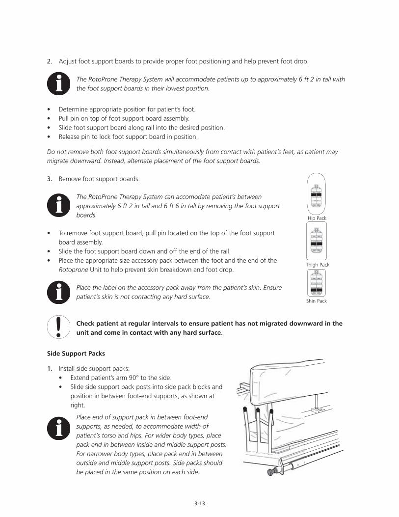
3. Remove foot support boards.
The RotoProne Therapy System can accomodate patient’s between approximately 6 ft 2 in tall and 6 ft 6 in tall by removing the foot support boards.
• To remove foot support board, pull pin located on the top of the foot support board assembly.
• Slide the foot support board down and off the end of the rail.• Place the appropriate size accessory pack between the foot and the end of the
Rotoprone Unit to help prevent skin breakdown and foot drop.
Place the label on the accessory pack away from the patient’s skin. Ensure patient’s skin is not contacting any hard surface.
Check patient at regular intervals to ensure patient has not migrated downward in the unit and come in contact with any hard surface.
Side Support Packs
1. Install side support packs:• Extend patient’s arm 90° to the side.• Slide side support pack posts into side pack blocks and
position in between foot-end supports, as shown at right.
Place end of support pack in between foot-end supports, as needed, to accommodate width of patient’s torso and hips. For wider body types, place pack end in between inside and middle support posts. For narrower body types, place pack end in between outside and middle support posts. Side packs should be placed in the same position on each side.
Hip Pack
Thigh Pack
Shin Pack

3-14
• Packs may also be switched from side-to-side to accommodate narrow or wide body types: - Assess patient to determine if packs need to taper in, as shown below left, or taper out, as
shown below right. - To place packs for narrow body type (tapered in), place pack with blue knob on patient left. Place
pack with green knob on patient right. - To place packs for wide body type (tapered out), place pack with green knob on patient left.
Place pack with blue knob on patient right.
If packs are switched, ensure slings are buckled onto the outside of the packs.
• Turn pack adjuster crank to position side packs snugly against patient’s sides. Side packs need to be tight enough to prevent patient from sliding from side-to-side when rotated.
Snugness of the side packs will vary according to each patient’s needs. Side packs need to be as tight as can be tolerated, as patients will shift slightly when rotated. Re-check packs each time patient is moved from supine to prone. Hand checks may be useful in determining if the side packs are too snug. Insert hand between patient’s sides and hips and side support pack as the packs are being positioned. When the packs feel snug against hand, remove hand and ensure the patient is secure. Be sure to check both sides of the patient.
Patient Right Patient Left Patient LeftPatient Right
Blue KnobGreen Knob Green KnobBlue Knob
PACKS TAPER IN FOR NARROW BODY TYPE PACKS TAPER OUT FOR WIDE BODY TYPE

3-15
• Install side support extension packs accessory from accessory bag, if needed for smaller patient.
If pack adjuster crank has been turned all the way in, but side support packs still do not fit snugly against patient’s upper body, use side support extension packs accessory to secure patient.
- Place extensions between patient’s sides and side support packs. - Perform hand check, as described above, to ensure patient is
secure.
• Extend top end of side support pack to support patient’s axilla, if necessary: - Pull knob (green or blue) up and hold. - Slide and extend pack end toward patient’s axilla
until patient is secure, as shown at right. - Release knob. Ensure end of pack is locked into
desired position. - U-shaped accessory pack should be used if side
support packs are extended to prevent adipose tissue from migrating into gap to help prevent skin breakdown.
Maintain a one-inch clearance (approximately the width of two fingers) between the end of the side support pack and the patient’s axilla, as shown at right. Never place side support pack snugly against patient’s axilla. Undue pressure on axillary blood vessels and the brachial plexus may result.
• Insert patient’s arms into arm supports:
Consider the positioning of any tubes and lines when placing patient’s arms into the arm supports. Ensure lines are not kinked or pinched in buckles. Ensure lines have enough slack for rotation.
3-16
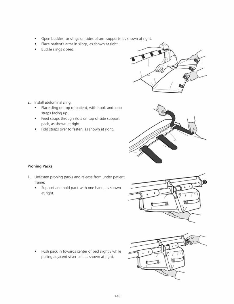
• Open buckles for slings on sides of arm supports, as shown at right.• Place patient’s arms in slings, as shown at right.• Buckle slings closed.
2. Install abdominal sling:• Place sling on top of patient, with hook-and-loop
straps facing up.• Feed straps through slots on top of side support
pack, as shown at right.• Fold straps over to fasten, as shown at right.
Proning Packs
1. Unfasten proning packs and release from under patient frame:• Support and hold pack with one hand, as shown
at right.
• Push pack in towards center of bed slightly while pulling adjacent silver pin, as shown at right.
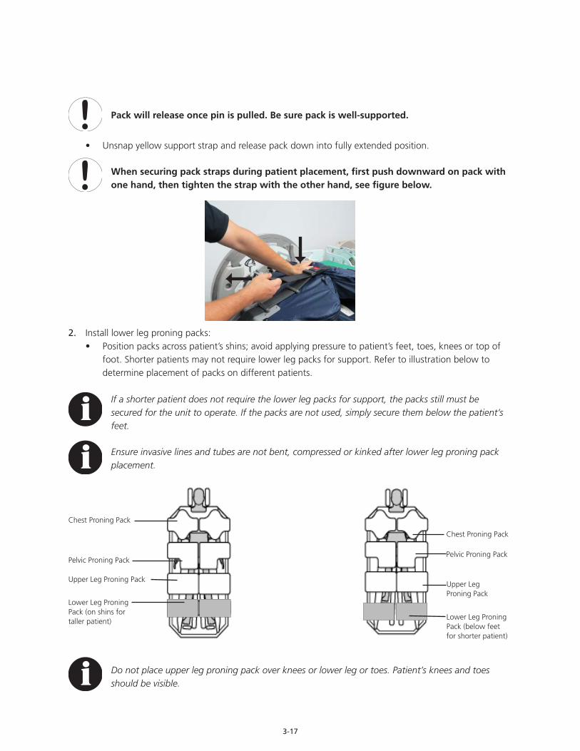
3-17
Pack will release once pin is pulled. Be sure pack is well-supported.
• Unsnap yellow support strap and release pack down into fully extended position.
When securing pack straps during patient placement, first push downward on pack with one hand, then tighten the strap with the other hand, see figure below.
2. Install lower leg proning packs:• Position packs across patient’s shins; avoid applying pressure to patient’s feet, toes, knees or top of
foot. Shorter patients may not require lower leg packs for support. Refer to illustration below to determine placement of packs on different patients.
If a shorter patient does not require the lower leg packs for support, the packs still must be secured for the unit to operate. If the packs are not used, simply secure them below the patient’s feet.
Ensure invasive lines and tubes are not bent, compressed or kinked after lower leg proning pack placement.
Do not place upper leg proning pack over knees or lower leg or toes. Patient’s knees and toes should be visible.
Chest Proning Pack
Chest Proning Pack
Pelvic Proning PackPelvic Proning Pack
Upper Leg Proning Pack
Upper Leg Proning Pack
Lower Leg Proning Pack (below feet for shorter patient)
Lower Leg Proning Pack (on shins for taller patient)
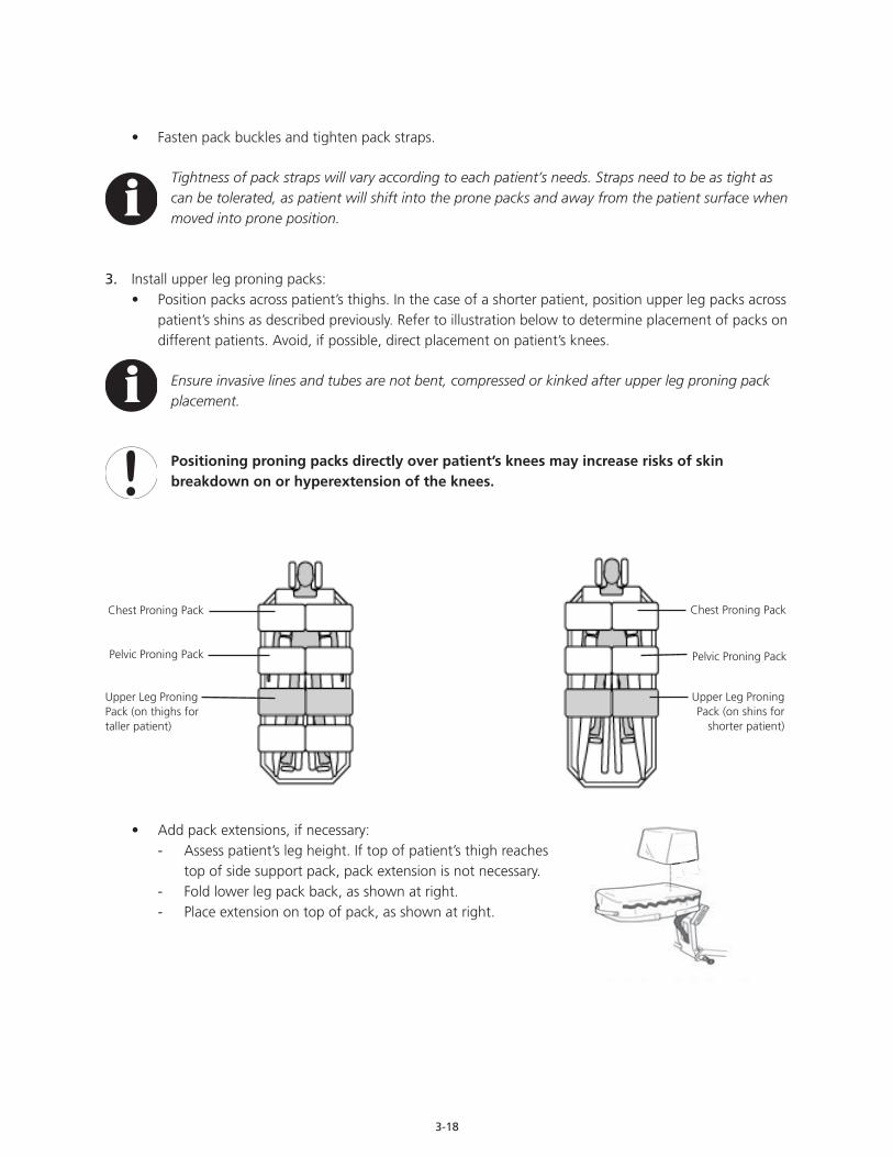
3-18
• Fasten pack buckles and tighten pack straps.
Tightness of pack straps will vary according to each patient’s needs. Straps need to be as tight as can be tolerated, as patient will shift into the prone packs and away from the patient surface when moved into prone position.
3. Install upper leg proning packs:• Position packs across patient’s thighs. In the case of a shorter patient, position upper leg packs across
patient’s shins as described previously. Refer to illustration below to determine placement of packs on different patients. Avoid, if possible, direct placement on patient’s knees.
Ensure invasive lines and tubes are not bent, compressed or kinked after upper leg proning pack placement.
Positioning proning packs directly over patient’s knees may increase risks of skin breakdown on or hyperextension of the knees.
• Add pack extensions, if necessary: - Assess patient’s leg height. If top of patient’s thigh reaches
top of side support pack, pack extension is not necessary. - Fold lower leg pack back, as shown at right. - Place extension on top of pack, as shown at right.
Chest Proning PackChest Proning Pack
Pelvic Proning PackPelvic Proning Pack
Upper Leg Proning Pack (on shins for
shorter patient)
Upper Leg Proning Pack (on thighs for taller patient)
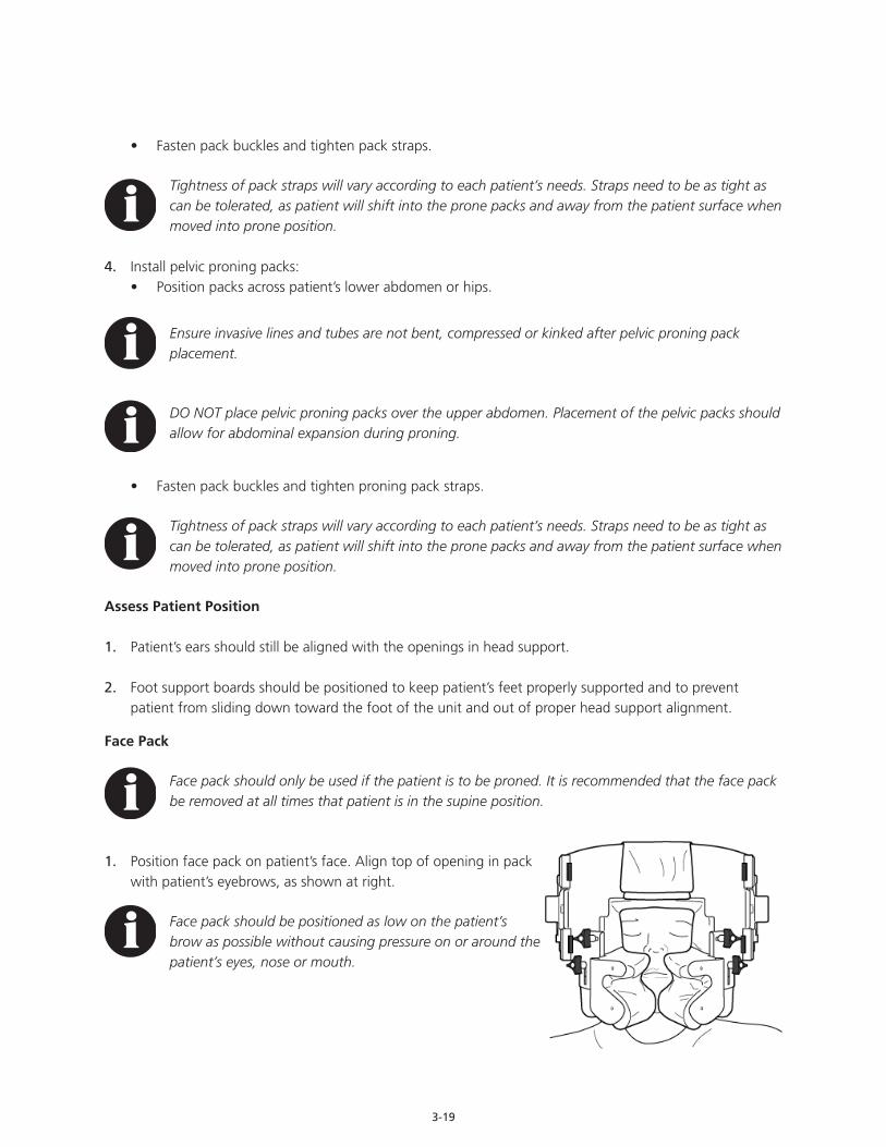
3-19
• Fasten pack buckles and tighten pack straps.
Tightness of pack straps will vary according to each patient’s needs. Straps need to be as tight as can be tolerated, as patient will shift into the prone packs and away from the patient surface when moved into prone position.
4. Install pelvic proning packs:• Position packs across patient’s lower abdomen or hips.
Ensure invasive lines and tubes are not bent, compressed or kinked after pelvic proning pack placement.
DO NOT place pelvic proning packs over the upper abdomen. Placement of the pelvic packs should allow for abdominal expansion during proning.
• Fasten pack buckles and tighten proning pack straps.
Tightness of pack straps will vary according to each patient’s needs. Straps need to be as tight as can be tolerated, as patient will shift into the prone packs and away from the patient surface when moved into prone position.
Assess Patient Position
1. Patient’s ears should still be aligned with the openings in head support.
2. Foot support boards should be positioned to keep patient’s feet properly supported and to prevent patient from sliding down toward the foot of the unit and out of proper head support alignment.
Face Pack
Face pack should only be used if the patient is to be proned. It is recommended that the face pack be removed at all times that patient is in the supine position.
1. Position face pack on patient’s face. Align top of opening in pack with patient’s eyebrows, as shown at right.
Face pack should be positioned as low on the patient’s brow as possible without causing pressure on or around the patient’s eyes, nose or mouth.
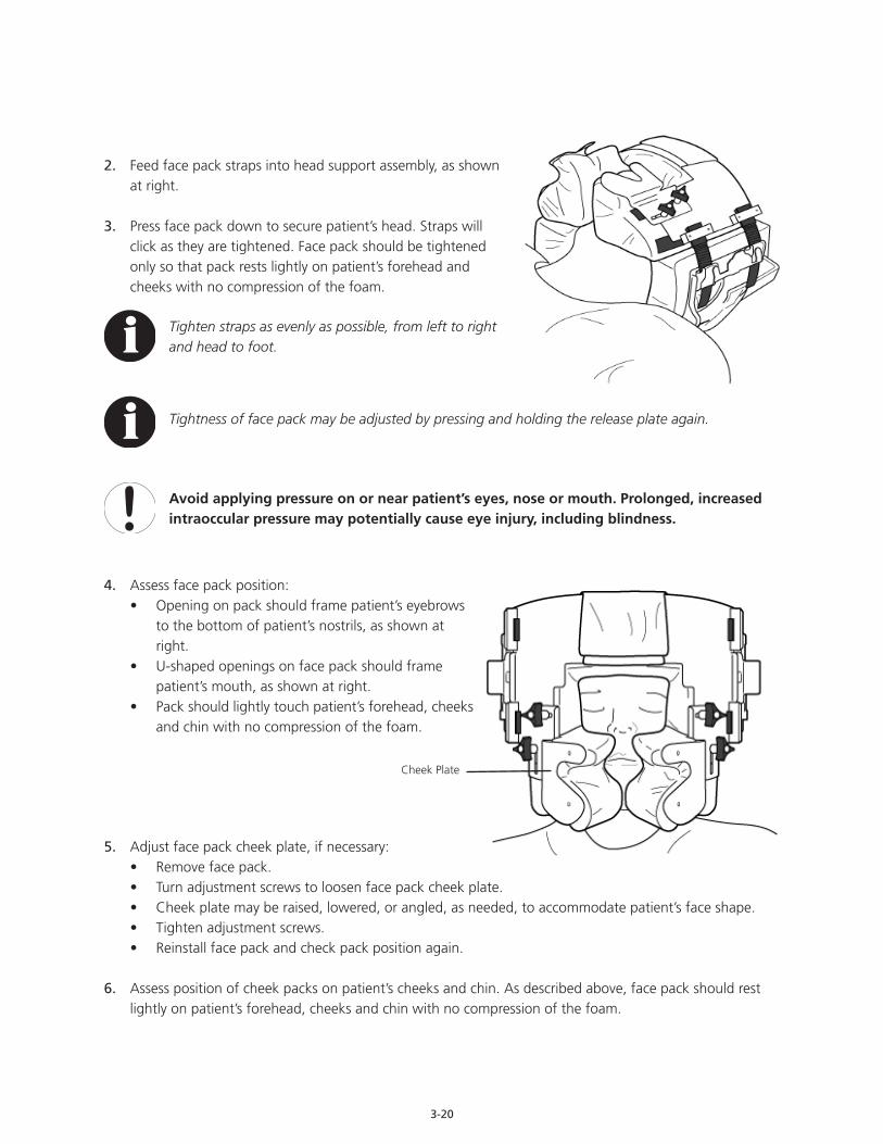
3-20
2. Feed face pack straps into head support assembly, as shown at right.
3. Press face pack down to secure patient’s head. Straps will click as they are tightened. Face pack should be tightened only so that pack rests lightly on patient’s forehead and cheeks with no compression of the foam.
Tighten straps as evenly as possible, from left to right and head to foot.
Tightness of face pack may be adjusted by pressing and holding the release plate again.
Avoid applying pressure on or near patient’s eyes, nose or mouth. Prolonged, increased intraoccular pressure may potentially cause eye injury, including blindness.
4. Assess face pack position:• Opening on pack should frame patient’s eyebrows
to the bottom of patient’s nostrils, as shown at right.
• U-shaped openings on face pack should frame patient’s mouth, as shown at right.
• Pack should lightly touch patient’s forehead, cheeks and chin with no compression of the foam.
5. Adjust face pack cheek plate, if necessary:• Remove face pack.• Turn adjustment screws to loosen face pack cheek plate.• Cheek plate may be raised, lowered, or angled, as needed, to accommodate patient’s face shape.• Tighten adjustment screws.• Reinstall face pack and check pack position again.
6. Assess position of cheek packs on patient’s cheeks and chin. As described above, face pack should rest lightly on patient’s forehead, cheeks and chin with no compression of the foam.
Cheek Plate
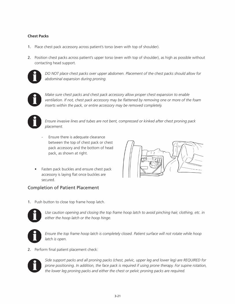
3-21
Chest Packs
1. Place chest pack accessory across patient’s torso (even with top of shoulder).
2. Position chest packs across patient’s upper torso (even with top of shoulder), as high as possible without contacting head support.
DO NOT place chest packs over upper abdomen. Placement of the chest packs should allow for abdominal expansion during proning.
Make sure chest packs and chest pack accessory allow proper chest expansion to enable ventilation. If not, chest pack accessory may be flattened by removing one or more of the foam inserts within the pack, or entire accessory may be removed completely.
Ensure invasive lines and tubes are not bent, compressed or kinked after chest proning pack placement.
- Ensure there is adequate clearance between the top of chest pack or chest pack accessory and the bottom of head pack, as shown at right.
• Fasten pack buckles and ensure chest pack accessory is laying flat once buckles are secured.
Completion of Patient Placement
1. Push button to close top frame hoop latch.
Use caution opening and closing the top frame hoop latch to avoid pinching hair, clothing, etc. in either the hoop latch or the hoop hinge.
Ensure the top frame hoop latch is completely closed. Patient surface will not rotate while hoop latch is open.
2. Perform final patient placement check:
Side support packs and all proning packs (chest, pelvic, upper leg and lower leg) are REQUIRED for prone positioning. In addition, the face pack is required if using prone therapy. For supine rotation, the lower leg proning packs and either the chest or pelvic proning packs are required.

3-22
• Ensure patient’s head is secure within head support. Adjust if necessary.• Ensure face pack (if using) is properly positioned. Adjust if necessary.• Ensure patient’s hands and arms are fastened securely within arm slings. Adjust if necessary.• Ensure side support packs are snug against patient’s sides. Adjust if necessary.• Ensure all proning pack buckles are securely fastened and straps adequately tightened.• Tighten chest pack just before proning.
Do not tighten chest pack until immediately before proning. Open back chest hatch after proning to allow for adequate chest expansion.
Tightness of pack straps will vary according to each patient’s needs. Straps need to be as tight as can be tolerated while allowing for proper chest expansion during ventilation. Patient will shift into the prone packs and away from the patient surface when moved into prone position.
3. Perform initial patient weighing and save the dated initial weight in the Weight Trend Chart:
Scales / patient weights are for reference only. Scale readings should not be relied upon for medication dosage.
• From the Home / Pull Lock Pin screen, press Scale button. The Scale screen will appear.
• Press Weight Trends button. The Weight Trends screen will appear.
• Press Save In Weight Trends button to save current weight in Weight Trend Chart.
• Verify initial weight and date are shown on the first line of the display.
The top line of the Weight Trend Chart will display the date and initial weight. This line is for reference and will not change. When future weight readings are taken and entered into the Weight Trend Chart, the most recent reading will appear on the top line of the display. This information will move up one line each time a new weight reading is saved into the Weight Trend Chart, and will eventually move up and off the display.
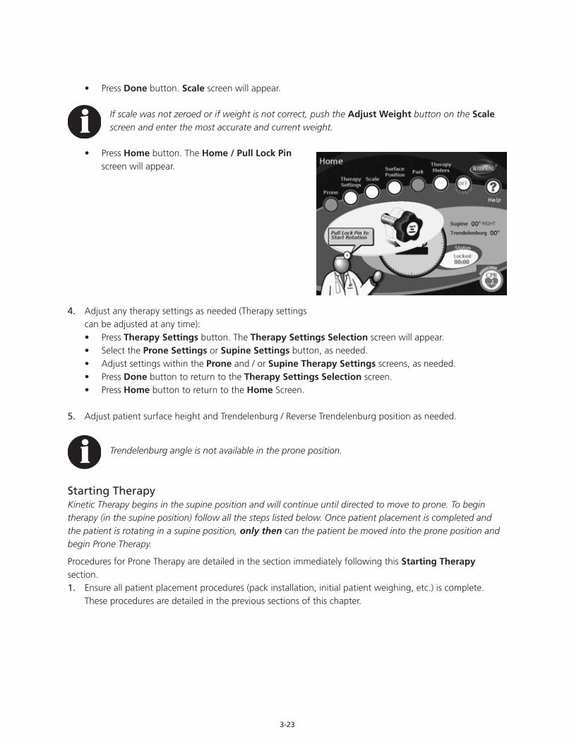
3-23
• Press Done button. Scale screen will appear.
If scale was not zeroed or if weight is not correct, push the Adjust Weight button on the Scale screen and enter the most accurate and current weight.
• Press Home button. The Home / Pull Lock Pin screen will appear.
4. Adjust any therapy settings as needed (Therapy settings can be adjusted at any time):• Press Therapy Settings button. The Therapy Settings Selection screen will appear.• Select the Prone Settings or Supine Settings button, as needed.• Adjust settings within the Prone and / or Supine Therapy Settings screens, as needed.• Press Done button to return to the Therapy Settings Selection screen.• Press Home button to return to the Home Screen.
5. Adjust patient surface height and Trendelenburg / Reverse Trendelenburg position as needed.
Trendelenburg angle is not available in the prone position.
Starting TherapyKinetic Therapy begins in the supine position and will continue until directed to move to prone. To begin therapy (in the supine position) follow all the steps listed below. Once patient placement is completed and the patient is rotating in a supine position, only then can the patient be moved into the prone position and begin Prone Therapy.
Procedures for Prone Therapy are detailed in the section immediately following this Starting Therapy section.1. Ensure all patient placement procedures (pack installation, initial patient weighing, etc.) is complete.
These procedures are detailed in the previous sections of this chapter.

3-24
2. Pull lock pin. The Checklist screen will appear.
3. Check and clear each item on the checklist:
To clear each item, press the corresponding button. The arrow will change to a check mark.
• Assess all invasive lines and tubes. Ensure lines are secure and have adequate slack to avoid pulling, tangling, binding or dislodging during a full 360° of rotation. Once all lines are assessed to be adequately secured, press Check Tubing button.
• Examine patient’s artificial airway system. Ensure ETT and ventilator tubing are secure and have adequate slack to avoid pulling or twisting during a full 360° of rotation. Once the airway is assessed to be adequately secured, press Check Airway button.
Consider labeling emergency medication line for rapid access.
• Examine patient’s placement in head support assembly. Ensure patient’s ears are aligned with openings in the sides of head support assembly. Ensure patient’s eyebrows are aligned with top of opening in face pack. Ensure that face pack (if used) is positioned so that patient’s eyes are visible and no part of pack places pressure on or around the eye and orbit area. Ensure face pack straps are secure and tightened appropriately. Once patient’s head is cleared, press Check Head Support button.
Tightness of straps will vary according to each patient’s needs. Secure straps snugly to minimize patient’s shift away from patient surface when moved into a prone position.
• Once checklist has been cleared, the Start Rotation screen will appear.
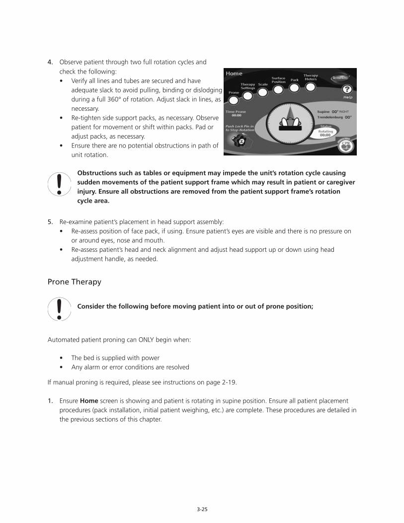
3-25
4. Observe patient through two full rotation cycles and check the following:• Verify all lines and tubes are secured and have
adequate slack to avoid pulling, binding or dislodging during a full 360° of rotation. Adjust slack in lines, as necessary.
• Re-tighten side support packs, as necessary. Observe patient for movement or shift within packs. Pad or adjust packs, as necessary.
• Ensure there are no potential obstructions in path of unit rotation.
Obstructions such as tables or equipment may impede the unit’s rotation cycle causing sudden movements of the patient support frame which may result in patient or caregiver injury. Ensure all obstructions are removed from the patient support frame’s rotation cycle area.
5. Re-examine patient’s placement in head support assembly:• Re-assess position of face pack, if using. Ensure patient’s eyes are visible and there is no pressure on
or around eyes, nose and mouth.• Re-assess patient’s head and neck alignment and adjust head support up or down using head
adjustment handle, as needed.
Prone Therapy
Consider the following before moving patient into or out of prone position;
Automated patient proning can ONLY begin when:
• The bed is supplied with power• Any alarm or error conditions are resolved
If manual proning is required, please see instructions on page 2-19.
1. Ensure Home screen is showing and patient is rotating in supine position. Ensure all patient placement procedures (pack installation, initial patient weighing, etc.) are complete. These procedures are detailed in the previous sections of this chapter.
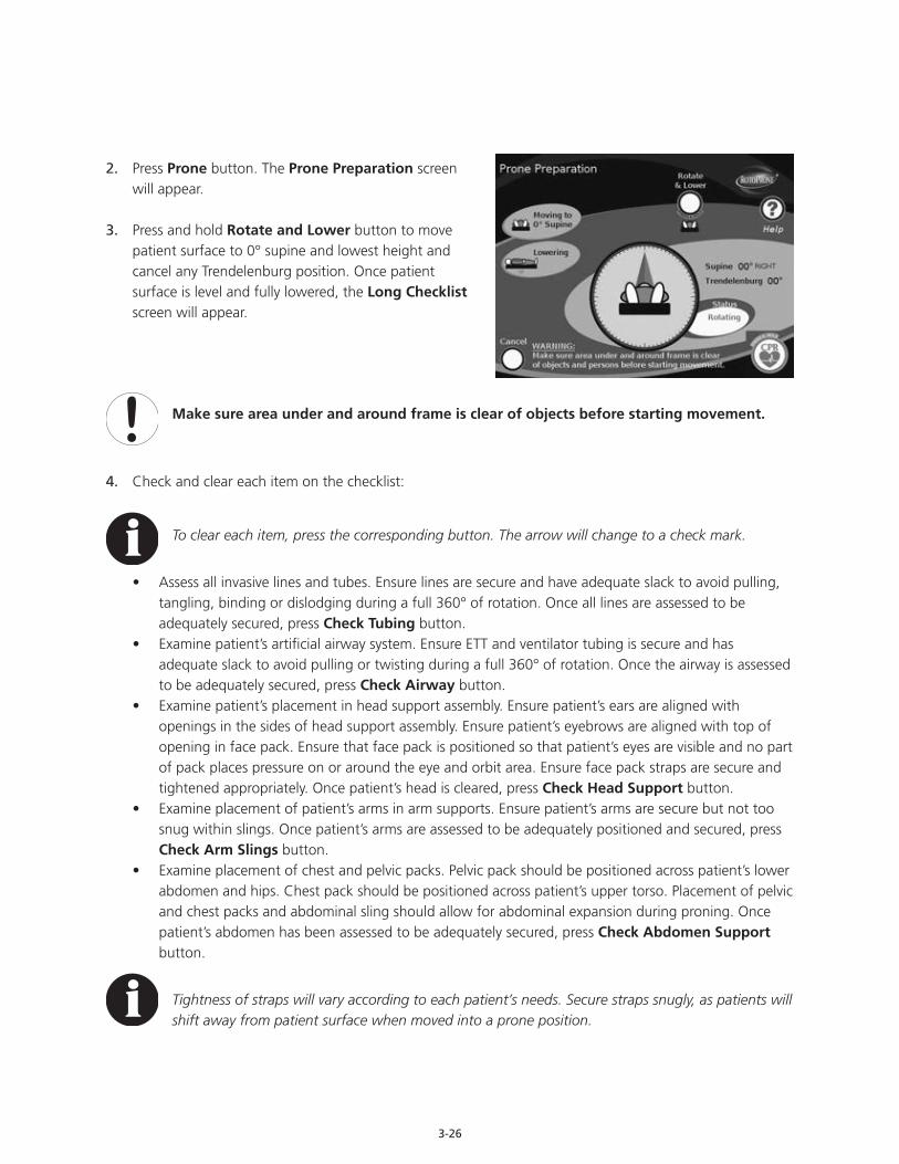
3-26
2. Press Prone button. The Prone Preparation screen will appear.
3. Press and hold Rotate and Lower button to move patient surface to 0° supine and lowest height and cancel any Trendelenburg position. Once patient surface is level and fully lowered, the Long Checklist screen will appear.
Make sure area under and around frame is clear of objects before starting movement.
4. Check and clear each item on the checklist:
To clear each item, press the corresponding button. The arrow will change to a check mark.
• Assess all invasive lines and tubes. Ensure lines are secure and have adequate slack to avoid pulling, tangling, binding or dislodging during a full 360° of rotation. Once all lines are assessed to be adequately secured, press Check Tubing button.
• Examine patient’s artificial airway system. Ensure ETT and ventilator tubing is secure and has adequate slack to avoid pulling or twisting during a full 360° of rotation. Once the airway is assessed to be adequately secured, press Check Airway button.
• Examine patient’s placement in head support assembly. Ensure patient’s ears are aligned with openings in the sides of head support assembly. Ensure patient’s eyebrows are aligned with top of opening in face pack. Ensure that face pack is positioned so that patient’s eyes are visible and no part of pack places pressure on or around the eye and orbit area. Ensure face pack straps are secure and tightened appropriately. Once patient’s head is cleared, press Check Head Support button.
• Examine placement of patient’s arms in arm supports. Ensure patient’s arms are secure but not too snug within slings. Once patient’s arms are assessed to be adequately positioned and secured, press Check Arm Slings button.
• Examine placement of chest and pelvic packs. Pelvic pack should be positioned across patient’s lower abdomen and hips. Chest pack should be positioned across patient’s upper torso. Placement of pelvic and chest packs and abdominal sling should allow for abdominal expansion during proning. Once patient’s abdomen has been assessed to be adequately secured, press Check Abdomen Support button.
Tightness of straps will vary according to each patient’s needs. Secure straps snugly, as patients will shift away from patient surface when moved into a prone position.

3-27
• Once checklist has been cleared, the Face Pack Caution screen will appear and an alert beep will sound.
• Manually pull up on face pack to ensure it is attached securely.
5. Re-examine patient’s placement in head support assembly, paying particular attention to the position of face pack. When head position is satisfactory, press Confirm button. The Move To Prone screen will appear.
Ensure all four proning pack buckles are fastened and straps are securely tightened before proning patient. Patient may shift when rotated. Re-assess and tighten, as needed.
6. Use the hand control located at the head of the unit or button on main screen to move the patient into prone position. Watch lines and tubes carefully to ensure they do not catch, tangle or become twisted.
Hold button until the patient surface is at 0° prone. The Checklist screen will reappear.
Be aware that the head support will shift downward slightly to compensate for patient compression into the prone packs.
If rotation is interrupted while the patient is moving to the prone position, the Interrupted Rotation screen will appear. Press the Continue button to resume moving the patient surface into the full 0° prone position.
Notice that the Interrupted Rotation screen also provides fast or slow rotation options. Press the corresponding button to change the speed at which the patient surface moves into prone or supine position. This will not change the speed at which the patient surface rotates during Kinetic Therapy.
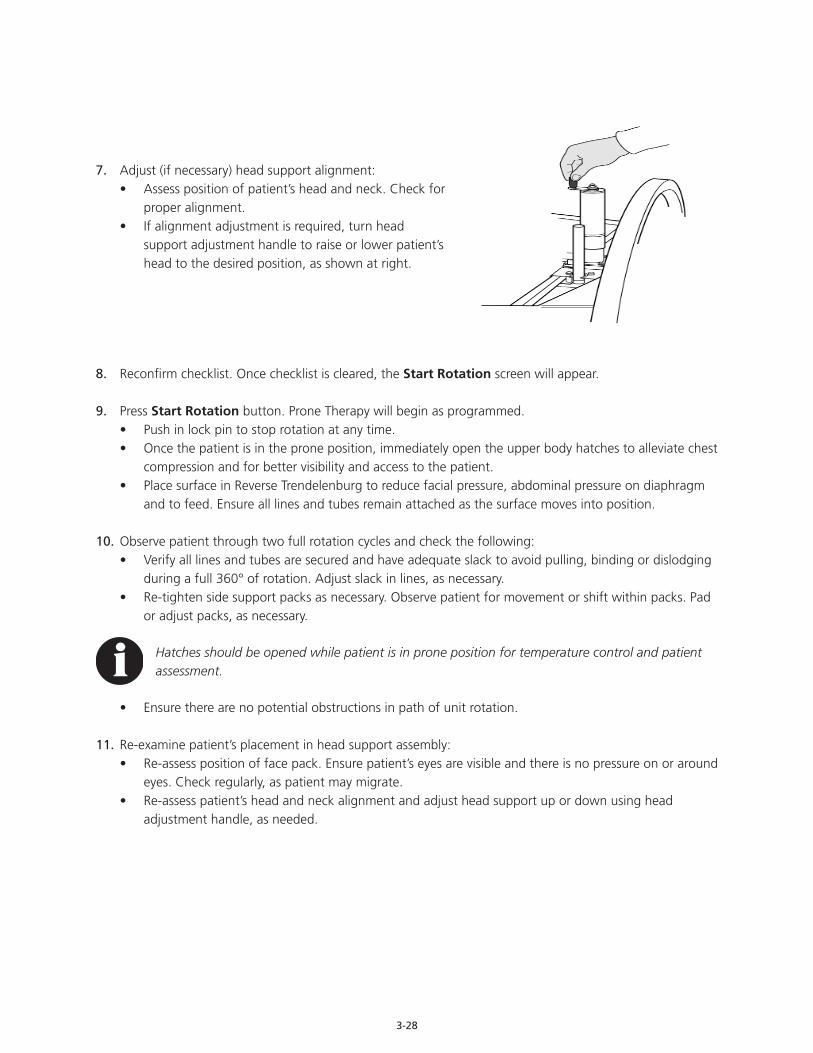
3-28
7. Adjust (if necessary) head support alignment:• Assess position of patient’s head and neck. Check for
proper alignment.• If alignment adjustment is required, turn head
support adjustment handle to raise or lower patient’s head to the desired position, as shown at right.
8. Reconfirm checklist. Once checklist is cleared, the Start Rotation screen will appear.
9. Press Start Rotation button. Prone Therapy will begin as programmed.• Push in lock pin to stop rotation at any time.• Once the patient is in the prone position, immediately open the upper body hatches to alleviate chest
compression and for better visibility and access to the patient.• Place surface in Reverse Trendelenburg to reduce facial pressure, abdominal pressure on diaphragm
and to feed. Ensure all lines and tubes remain attached as the surface moves into position.
10. Observe patient through two full rotation cycles and check the following:• Verify all lines and tubes are secured and have adequate slack to avoid pulling, binding or dislodging
during a full 360° of rotation. Adjust slack in lines, as necessary.• Re-tighten side support packs as necessary. Observe patient for movement or shift within packs. Pad
or adjust packs, as necessary.
Hatches should be opened while patient is in prone position for temperature control and patient assessment.
• Ensure there are no potential obstructions in path of unit rotation.
11. Re-examine patient’s placement in head support assembly:• Re-assess position of face pack. Ensure patient’s eyes are visible and there is no pressure on or around
eyes. Check regularly, as patient may migrate. • Re-assess patient’s head and neck alignment and adjust head support up or down using head
adjustment handle, as needed.
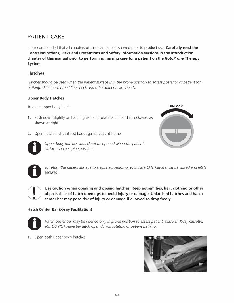
4-1
PATIENT CARE
It is recommended that all chapters of this manual be reviewed prior to product use. Carefully read the Contraindications, Risks and Precautions and Safety Information sections in the Introduction chapter of this manual prior to performing nursing care for a patient on the RotoProne Therapy System.
Hatches
Hatches should be used when the patient surface is in the prone position to access posterior of patient for bathing, skin check tube / line check and other patient care needs.
Upper Body Hatches
To open upper body hatch:
1. Push down slightly on hatch, grasp and rotate latch handle clockwise, as shown at right.
2. Open hatch and let it rest back against patient frame.
Upper body hatches should not be opened when the patient surface is in a supine position.
To return the patient surface to a supine position or to initiate CPR, hatch must be closed and latch secured.
Use caution when opening and closing hatches. Keep extremities, hair, clothing or other objects clear of hatch openings to avoid injury or damage. Unlatched hatches and hatch center bar may pose risk of injury or damage if allowed to drop freely.
Hatch Center Bar (X-ray Facilitation)
Hatch center bar may be opened only in prone position to assess patient, place an X-ray cassette, etc. DO NOT leave bar latch open during rotation or patient bathing.
1. Open both upper body hatches.

4-2
2. Pull bar latch toward foot of unit to open.
3. Lift bar, hold open and perform care.
4. Lower bar and ensure bar latch is securely closed.
Midline Hatch
To open midline hatch:
1. Push down slightly on hatch, grasp and rotate handle clockwise, as shown at right.
2. Open hatch and let it rest back against patient frame.
3. Restart Prone Therapy, as desired.
Midline hatch cannot be opened when the patient surface is in a supine position.
To return the patient surface to a supine position or to initiate CPR, hatch must be closed and latch secured.
Lower Body Hatch
To open lower body hatch:
1. Grasp and rotate latch handle clockwise, as shown at right.
2. Open hatch and let it rest back against patient frame.
Lower body hatch cannot be opened when the patient surface is in a supine position.
To return the patient surface to a supine position or to initiate CPR, hatch must be closed and latch secured.
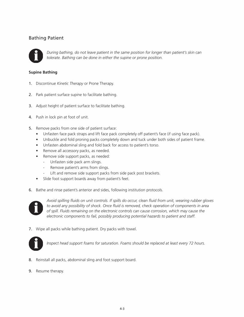
4-3
Bathing Patient
During bathing, do not leave patient in the same position for longer than patient’s skin can tolerate. Bathing can be done in either the supine or prone position.
Supine Bathing
1. Discontinue Kinetic Therapy or Prone Therapy.
2. Park patient surface supine to facilitate bathing.
3. Adjust height of patient surface to facilitate bathing.
4. Push in lock pin at foot of unit.
5. Remove packs from one side of patient surface:• Unfasten face pack straps and lift face pack completely off patient’s face (if using face pack).• Unbuckle and fold proning packs completely down and tuck under both sides of patient frame.• Unfasten abdominal sling and fold back for access to patient’s torso.• Remove all accessory packs, as needed.• Remove side support packs, as needed:
- Unfasten side pack arm slings. - Remove patient’s arms from slings. - Lift and remove side support packs from side pack post brackets.
• Slide foot support boards away from patient’s feet.
6. Bathe and rinse patient’s anterior and sides, following institution protocols.
Avoid spilling fluids on unit controls. If spills do occur, clean fluid from unit, wearing rubber gloves to avoid any possibility of shock. Once fluid is removed, check operation of components in area of spill. Fluids remaining on the electronic controls can cause corrosion, which may cause the electronic components to fail, possibly producing potential hazards to patient and staff.
7. Wipe all packs while bathing patient. Dry packs with towel.
Inspect head support foams for saturation. Foams should be replaced at least every 72 hours.
8. Reinstall all packs, abdominal sling and foot support board.
9. Resume therapy.
4-4
Prone Bathing
1. Park patient surface prone to facilitate bathing and access to patient’s posterior.
2. Push in lock pin at foot of bed.
3. Open upper body hatches, if not already open.
It is recommended that all hatches be opened when patient is in the prone position. Hatch center bar may be opened briefly to facilitate cleaning.
4. Bathe and rinse patient’s posterior, following institution protocols.
5. Wipe and rinse upper body hatch packs while bathing patient. Dry packs with towel.
6. Return upper hatches to semi-closed position, with hatches resting on frame.
7. Open midline hatch, if not already open.
8. Bathe and rinse patient’s posterior following institution protocols.
9. Wipe and rinse midline hatch packs while bathing patient. Dry packs with towel.
10. Return midline hatch to semi-closed position, with hatch resting on frame.
11. Open lower body hatch.
12. Bathe and rinse patient’s posterior, following institution protocols.
13. Wipe and rinse lower body hatch packs while bathing patient. Dry packs with towel.
14. Return lower body hatch to semi-closed position, with hatch resting on frame.
15. Pull out lock pin at foot of unit.
16. Resume therapy, as needed.

4-5
Skin Care
Consider these steps to help manage potential skin complications that can be associated with Prone Therapy:
Fitting the head support, face pack or other packs too tightly may increase pressure points, possibly leading to skin breakdown. Assess skin at frequent intervals depending on patient condition (at least every four hours). Give extra attention to skin at pressure points and locations where moisture or incontinence may occur or collect. Common pressure points include, but are not limited to, the face, ears, axilla, shoulders, sides and upper and lower extremities. Early intervention may be critical to preventing serious skin breakdown.
• Remove excess moisture and keep skin dry and clean at all times.• Check patient skin regularly, particularly in areas where pressure, incontinence and drainage occur.• Place prophylactic shear / pressure pads (hydrophilic polyurethane foam pads) on sacrum, elbows, cheeks,
knees and anterior shoulders.• Apply absorbent white foam to pressure points on the face, forehead, cheeks and under tubing holder.• Apply hydrocolloid dressing or hydrophilic foam dressing on the forehead and chin.• Lubricate and cover eyes to prevent corneal abrasion.• Apply moisture barrier ointment to patient’s skin before securing proning packs on patient.• Place hydrocolloid dressing at points where head support meets top of shoulders, axille and / or other
pressure points.• Move ECG electrodes to the patient’s back.• Avoid using foot splints during Prone Therapy.
Face
Facial edema may be common during Prone Therapy. Consider these guidelines to help protect against swelling, particularly noting the cheeks and forehead:
• Remove face pack at all times patient is in supine position.• Remove face pack at regular intervals to assess the eyes and surrounding skin.• Make sure that face pack does not touch the eyes and only lightly touches the face.• Assess face for skin breakdown and assess tongue for gross edema.• Place cool packs on face.• Place wet cloths or four by four gauze over protruding or swollen tongues.• Place patient in reverse Trendelenburg position to help minimize facial swelling / edema.• Change face pack foam every 72 hours or as needed.
Axilla
• Maintain a one-inch clearance (approximately the width of two fingers) between the end of the side support pack and the patient’s axilla, as shown at right.
Never place side support pack snugly against patient’s axilla. Undue pressure on the axilla may result in nerve damage.
4-6
Shoulders and Iliac Crest
Both the shoulders and the iliac crest bear much of the patient’s weight, making them susceptible to skin breakdown. Consider these precautions:
• When prone, open as many back hatches of the RotoProne Therapy System as possible to help minimize risk of skin breakdown and provide maximal lung expansion.
Always make sure hatches are closed and locked in position prior to rotating patient surface.
• Adjust support padding, as needed.
Feet
Friction on the feet can also contribute to skin breakdown. Consider these precautions;
• When supine, elevate heels off of therapy surface.• Continue using sequential compression devices (SCDs) during prone therapy if ordered by treating
physician.
Incontinence / Drainage
1. ArjoHuntleigh’s Dri-Flo™ Breathable Underpads are recommended for incontinent patients to minimize soiling of packs.
2. Disposable diapers or incontinent pads may be used.
3. Assess for incontinence or drainage regularly and provide appropriate skin care following each episode.
Foot Support
Use foot support boards to help prevent foot drop. Adjust boards to provide proper foot positioning:
• Determine appropriate position for patient’s feet.• Pull pin on top of board assembly.• Slide foot support board into appropriate position.• Release pin.
Do not remove both foot boards simultaneously, as patient may migrate downward. Instead alternate placement of the foot support boards.
Side-Lying Head Position
When patient is lying in static prone or supine position, patient’s head may be moved into a right or left side-lying position.
Neck strain may occur if patient surface is rotated while patient’s head is in side-lying position.
4-7
Patient Transfer From the RotoProne Therapy System
Do not leave patient unattended at any time during patient transfer.
1. Discontinue Kinetic Therapy or Prone Therapy.
2. Return patient surface to 0° supine and 0° Trendelenburg and secure.
3. Push in lock pin at foot of unit.
4. Adjust height of patient surface to same level as surface to which patient is being transferred.
5. Ensure all four caster brakes on both surfaces are locked.
6. Remove all packs and abdominal sling.
Refer to the Patient Placement chapter of this manual for detailed pack removal instructions.
Place packs on a clean surface. DO NOT PLACE PACKS ON FLOOR.
7. Open top frame hoop latch:• Pull knob.• Pull hoop back until it locks open.
Use caution opening and closing the top frame hoop latch to avoid pinching hair, clothing, etc. in either the hoop latch or the hoop hinge.
8. Remove face pack, if using.
9. Open head support.
10. Remove all patient support lines from tube management system.
11. Cover brackets and block for leg abductor and side support packs with washcloths or similar padding on side of patient surface across which the patient will be transferred. Washcloths will pad the brackets and help ensure patient comfort during transfer.
12. Transfer patient following all applicable safety rules and institutional protocols.

4-8

5-1
POWER-DOWN PROCEDURES
The RotoProne Therapy System is not recommended for patient transport. Should there be an emergency situation where hospital personnel transport the patient while on the RotoProne Unit, care should be taken in doorways and elevators or in any situation where casters can get caught. A minimum of two persons are recommended for emergency transport.
Care should be taken prior to RotoProne placement to ensure the unit fits in facility elevators. Use the following procedures to power down the RotoProne for intra-facility transport (for storage or maintenance) or for shipping between facilities.
Power-Down for Intra-Facility Transport / Storage
1. Discontinue therapy.
2. Ensure patient surface is at 0° supine.
3. Push Lock Pin in.
4. Transfer patient from unit.
See Patient Care section of this manual for detailed instructions on patient transfer.
5. Press and hold OFF button on Home screen. Shutdown Information screen will appear and alarm will sound.
Alarm will sound until one of the buttons on the screen is pressed.
All settings will be held in memory and restored when the unit is plugged in.
6. Press Transport button (on the left side of the screen).If the patient surface is not already leveled and lowered, the Lock Pin Out screen will appear.
If the patient surface is leveled and lowered and the Lock Pin is already pushed in, the Transport Height Information screen (described as follows in Step 9) will appear.
7. Pull Lock Pin. Rotate and Lower Information screen will appear.
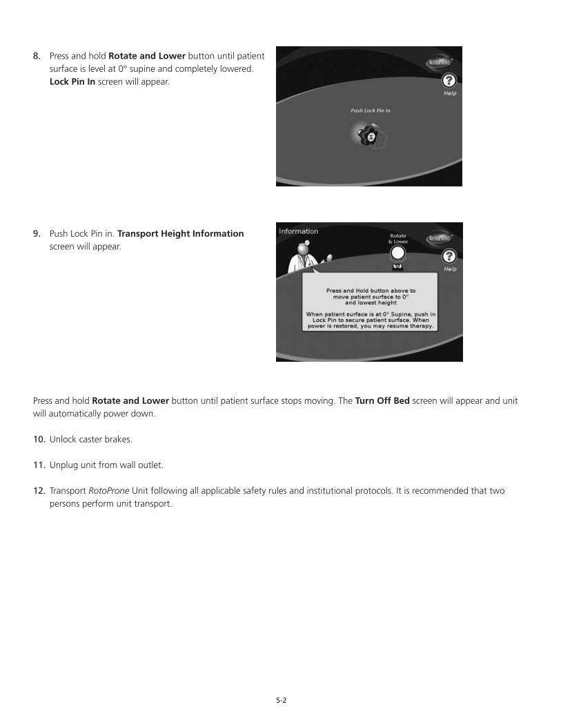
5-2
8. Press and hold Rotate and Lower button until patient surface is level at 0° supine and completely lowered. Lock Pin In screen will appear.
9. Push Lock Pin in. Transport Height Information screen will appear.
Press and hold Rotate and Lower button until patient surface stops moving. The Turn Off Bed screen will appear and unit will automatically power down.
10. Unlock caster brakes.
11. Unplug unit from wall outlet.
12. Transport RotoProne Unit following all applicable safety rules and institutional protocols. It is recommended that two persons perform unit transport.
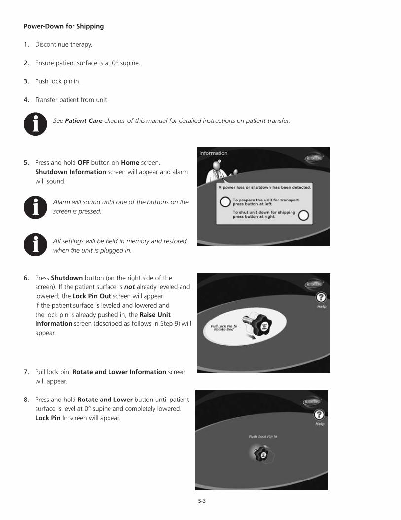
5-3
Power-Down for Shipping
1. Discontinue therapy.
2. Ensure patient surface is at 0° supine.
3. Push lock pin in.
4. Transfer patient from unit.
See Patient Care chapter of this manual for detailed instructions on patient transfer.
5. Press and hold OFF button on Home screen. Shutdown Information screen will appear and alarm will sound.
Alarm will sound until one of the buttons on the screen is pressed.
All settings will be held in memory and restored when the unit is plugged in.
6. Press Shutdown button (on the right side of the screen). If the patient surface is not already leveled and lowered, the Lock Pin Out screen will appear.If the patient surface is leveled and lowered and the lock pin is already pushed in, the Raise Unit Information screen (described as follows in Step 9) will appear.
7. Pull lock pin. Rotate and Lower Information screen will appear.
8. Press and hold Rotate and Lower button until patient surface is level at 0° supine and completely lowered. Lock Pin In screen will appear.
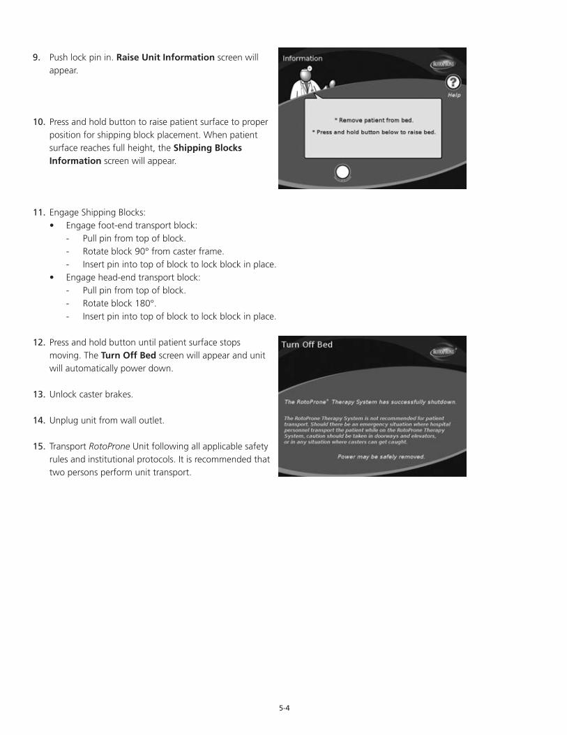
5-4
9. Push lock pin in. Raise Unit Information screen will appear.
10. Press and hold button to raise patient surface to proper position for shipping block placement. When patient surface reaches full height, the Shipping Blocks Information screen will appear.
11. Engage Shipping Blocks:• Engage foot-end transport block:
- Pull pin from top of block. - Rotate block 90° from caster frame. - Insert pin into top of block to lock block in place.
• Engage head-end transport block: - Pull pin from top of block. - Rotate block 180°. - Insert pin into top of block to lock block in place.
12. Press and hold button until patient surface stops moving. The Turn Off Bed screen will appear and unit will automatically power down.
13. Unlock caster brakes.
14. Unplug unit from wall outlet.
15. Transport RotoProne Unit following all applicable safety rules and institutional protocols. It is recommended that two persons perform unit transport.
6-1
CARE AND CLEANING
The following are the ArjoHuntleigh-recommended daily cleaning and infection control procedures for the RotoProne Therapy System while it is in use. If the product is to be purchased or utilized for long term rentals, it is recommended that ArjoHuntleigh be contacted for recommended Infection Control Procedures to be utilized by the facility.
It is recommended that all chapters of this manual be reviewed prior to product use. Carefully read all the Contraindications, Risks and Precautions and Safety Information sections in the Introduction chapter of this manual prior to performing care and cleaning procedures on the RotoProne Therapy System.
Daily Care and Cleaning
Daily care and cleaning consists of wiping down the patient surface and packs (as needed) during patient bathing. The patient does not need to be removed from the bed when performing daily cleaning. Refer to Patient Bathing section for proper procedure.
Avoid spilling fluids on any part of the RotoProne Therapy Unit or hand control. Fluids remaining on electronic controls can cause corrosion, which may cause the electronic components to fail. Component failures may cause the unit to operate erratically, possibly producing potential hazards to patient and caregiver.
Daily Equipment CheckIn addition to cleaning, the following daily equipment check is recommended:
• Inspect face pack foams for saturation. Foams should be replaced at least every 72 hours or more frequently if soiled.
• Inspect packs, straps and proning pack buckles for wear. Ensure all are in good condition.• Inspect all straps for fraying or parting.• Ensure proning pack buckles lock securely.• If any of the packs, straps or buckles appear to require service or replacement, contact ArjoHuntleigh.
Preventive MaintenanceIt is recommended that all preventive and battery maintenance procedures be performed only by qualified ArjoHuntleigh service personnel or ArjoHuntleigh-approved personnel. Contact ArjoHuntleigh for further information regarding long-term equipment care and preventive maintenance issues.

6-2
7-1
SPECIFICATIONS *
Recommended Weight and HeightMaximum Recommended Patient Weight . . . . . . . . . . . . . . . . . . . . . . . . . . . . . . . . . . . . . . . 350 lb (159 kg)Minimum Recommended Patient Weight . . . . . . . . . . . . . . . . . . . . . . . . . . . . . . . . . . . . . . . . . 88 lb (40 kg)Maximum Recommended Patient Height . . . . . . . . . . . . . . . . . . . . . . . . . . . . . . . . . . . . . .6 ft 6 in (198 cm)Minimum Recommended Patient Height . . . . . . . . . . . . . . . . . . . . . . . . . . . . . . . . . . . . . . .4 ft 6 in (137 cm)Total Unit Weight . . . . . . . . . . . . . . . . . . . . . . . . . . . . . . . . . . . . . . . . . . . . . . . . . . . . . . . . 1240 lb (563 kg)
DimensionsLength (with accessories and bumpers) . . . . . . . . . . . . . . . . . . 93 in (237 cm) min / 101 in (257 cm) maxWidth . . . . . . . . . . . . . . . . . . . . . . . . . . . . . . . . . . . . . . . . . . . . . . . . . . . . . . . . . . . . . . 41 in (104.5 cm)Height (to patient surface) . . . . . . . . . . . . . . . . . . . . . . . . . . . . . 35 in (89 cm) min / 46 in (117 cm) maxHeight (to top of hoop) . . . . . . . . . . . . . . . . . . . . . . . . . . . . . . 51 in (130 cm) min / 62 in (158 cm) maxGround Clearance (surface lowered with shipping blocks) . 0.5 in (1.25 cm) min / 3.25 in (8.25 cm) max
ArticulationRotation Angle (to each side) . . . . . . . . . . . . . . . . . . . . . . . . . . . . . . . . . . . . . . . . . . . . . . . . . .up to 62°Trendelenburg / Reverse Trendelenburg (maximum) . . . . . . . . . . . . . . . . . . . . . . . . . . . . . . . +11° / -11°
ScaleScale Accuracy . . . . . . . . . . . . . . . . . . . . . . . . . . . . . . . . . . . . . . . . . . . . . . . . . .+ / - 1% patient weightScale Capacity (including patient, accessories and equipment) . . . . . . . . . . . . . . . . . . . . 500 lb (227 kg)
ElectricalVoltage . . . . . . . . . . . . . . . . . . . . . . . . . . . . . . . . . . . . . . . . . . . . . . . . . . . . . . . . . .115 VAC (230 VAC)Frequency . . . . . . . . . . . . . . . . . . . . . . . . . . . . . . . . . . . . . . . . . . . . . . . . . . . . . . . . . . . . . 60 Hz (50 Hz)Ampere Rating (maximum) . . . . . . . . . . . . . . . . . . . . . . . . . . . . . . . . . . . . . . . . . . . . . . . . . . . . . 8 AmpsMaximum Electrical Leakage . . . . . . . . . . . . . . . . . . . . . . . . . . . . . . . . . . . . . . Less than 100 MicroampsPower Cord . . . . . . . . . . . . . . . . . . . . . . . . . . . . . . . . . . . . . . . . . . . . . . . 10 ft (351 cm) Hospital Grade
United States federal law restricts this device to sale or rental by or on the order of a physician.
*Specifications subject to change without notice.
ClassificationClassification in accordance with UL 60601-1, CSA C22.2 No 601.1 and IEC 60601-1
• Class 1 and Internally Powered• Type B• IPX4• No Sterilization• Not for Use with Flammable Anesthetic Mixture with Air, Oxygen or Nitrous Oxide• Continuous Operation• Ordinary Equipment
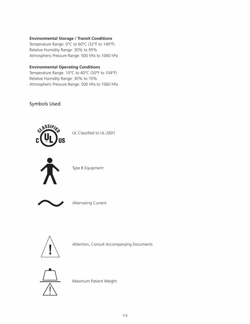
7-2
Environmental Storage / Transit ConditionsTemperature Range: 0°C to 60°C (32°F to 140°F)Relative Humidity Range: 30% to 95%Atmospheric Pressure Range: 500 hPa to 1060 hPa
Environmental Operating ConditionsTemperature Range: 10°C to 40°C (50°F to 104°F)Relative Humidity Range: 30% to 70%Atmospheric Pressure Range: 500 hPa to 1060 hPa
Symbols Used
UL Classified to UL-2601
Type B Equipment
Alternating Current
Attention, Consult Accompanying Documents
Maximum Patient Weight
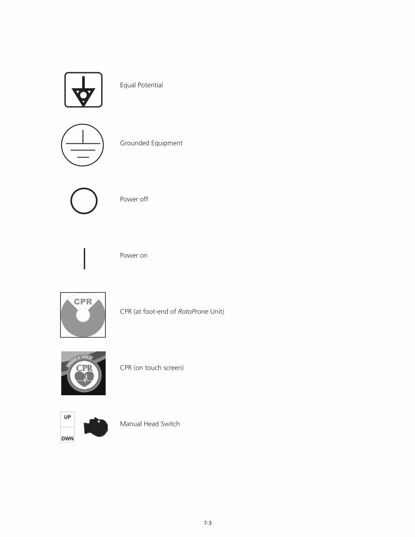
7-3
Equal Potential
Grounded Equipment
Power off
Power on
CPR (at foot-end of RotoProne Unit)
CPR (on touch screen)
Manual Head Switch

7-4
Manual Foot Switch
Electrical Shock
Electromagnetic Emissions Information
RotoProne Unit uses RF energy only for its internal function. Therefore, its RF emissions are very low and are not likely to cause interference in nearby electronic equipment. The RotoProne Unit was tested to the following standards:
• IEC 60601-1-2: Second Edition• EN 55011: 1998 Group 1, Class B• EN 61000-3-2: Class A• EN 61000-3-3• EN 61000-4-2: 1995 (6 / 8 kV)• EN 61000-4-3: 1995 (3 V / m)• EN 61000-4-4: 1995 (1 / 2 kV)• EN 61000-4-5: 1995 (2 / 1 kV)• EN 61000-4-6: 1996 (3 VRMS)• EN 61000-4-8: 1994 (10 A / m)• EN 61000-4-11: 1994 (>95%-0.5p, 30%-25p, >95%-250p)
UP
DWN

8-1
QUESTIONS AND INFORMATION
Contact InformationFor questions regarding this product, supplies, maintenance or additional information about ArjoHuntleigh products and service, please contact ArjoHuntleigh or an ArjoHuntleigh authorized representative. 1-844-557-7663www.arjohuntleigh.com
® and ™ are trademarks belonging to the ArjoHuntleigh group of companies © ArjoHuntleigh 2016. 208662-AH Rev D • 05/2016

Getinge Group is a leading global provider of products and systems that contribute to quality enhancement and cost efficiency within healthcare and life sciences. We operate under the three brands of ArjoHuntleigh, Getinge and Maquet. Getinge provides solutions for infection control within healthcare and contamination prevention within life sciences. Maquet specializes in solutions, therapies and products for surgical interventions, interventional cardiology and intensive care.
ArjoHuntleigh focuses on patient handling and hygiene, disinfection, DVT prevention, medical beds, therapeutic surfaces and diagnostics.
ArjoHuntleigh ABHans Michelsensgatan 10 211 20 Malmö, Swedenwww.arjohuntleigh.com


