23
1 98-20001 Rev 3 5/10/2011 ROTORK RCM700 Series Electro-Hydraulic Fail-Safe Actuator Installation and Operating Instructions For Both Weather Proof and Explosion Proof Models
| Date post: | 12-Mar-2018 |
| Category: |
Documents |
| Upload: | vuongthien |
| View: | 240 times |
| Download: | 2 times |

1 98-20001 Rev 3 5/10/2011
ROTORK RCM700 Series
Electro-Hydraulic
Fail-Safe Actuator
Installation and Operating Instructions
For Both Weather Proof and
Explosion Proof Models

2 98-20001 Rev 3 5/10/2011
CONTENT: PRINCIPLE OF OPERATION ....................................................................................... 3
MAINTANENCE .............................................................................................................. 3
INSTALLATION .............................................................................................................. 4
RCI200 Hydraulic Actuator............................................................................................. 5
M404 Hydraulic Power Unit .......................................................................................... 12
Electric Motor Data ........................................................................................................ 14
Solenoid Valve ................................................................................................................. 15
2-Position Switch Box ..................................................................................................... 19
Modulating Switch Box .................................................................................................. 20
Revision History .............................................................................................................. 23

3 98-20001 Rev 3 5/10/2011
PRINCIPLE OF OPERATION The Rotork RCM700 actuator consists of a hydraulically prepped Rotork actuator, a self contained electrically operated ½ hp motor, a hydraulic pump and reservoir, 2-way normally open solenoid (SRH Units), directional control valve (DAH Units) and an end of stroke limit switch used to shut off the motor at the end of actuator travel.
Caution Improper setting of the end of stroke travel limit switch cam will result in the pump
not shutting off at the end of full travel. Failsafe (SRH Unit): When the actuator is energized, the solenoid closes and the pump forces oil into the actuator compressing the springs and stroking the actuator to the energized position. When the actuator is de-energized the 2-way solenoid opens this allows the actuator springs to take over, pushing the oil out of the actuator and back into the reservoir, the actuator is now in the fail safe position. Non-Failsafe (DAH Unit): When the actuator is energized (Coil a) the solenoid spool shifts to designated position, the pump forces oil into the actuator and stroking the actuator to the energized position. When the actuator is energized (Coil b) in opposite direction the solenoid spool shifts again, this allows the pump to force oil into the outer chamber stroking the actuator in the opposite direction; thus pushing the oil out of the actuator and back into the reservoir.
Preventative Maintenance An overall visual inspection once a month is good practice. With the actuator de-energized, check fittings for tightness and verify that the oil level in the reservoir is at approximately 1” below the breather. ***Add Oil if Necessary*** RECOMMENDED REPLACEMENT OIL:
- Chevron Rando HDZ - Range: -20°F to +175°F
4 98-20001 Rev 3 5/10/2011
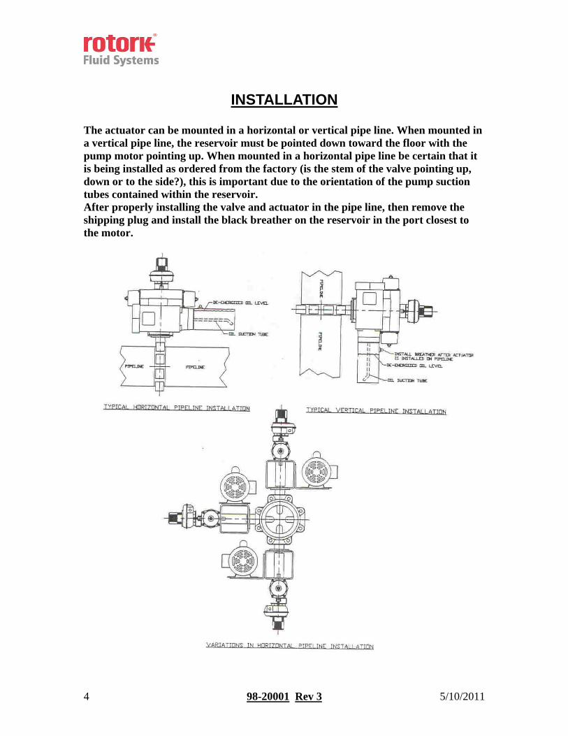
INSTALLATION The actuator can be mounted in a horizontal or vertical pipe line. When mounted in a vertical pipe line, the reservoir must be pointed down toward the floor with the pump motor pointing up. When mounted in a horizontal pipe line be certain that it is being installed as ordered from the factory (is the stem of the valve pointing up, down or to the side?), this is important due to the orientation of the pump suction tubes contained within the reservoir. After properly installing the valve and actuator in the pipe line, then remove the shipping plug and install the black breather on the reservoir in the port closest to the motor.

5 98-20001 Rev 3 5/10/2011
RCI200 Hydraulic Actuator Introduction:
- RCI compact hydraulic actuators are intended for on-off and modulating control on quarter-turn valves and dampers. The design features a modern Scotch-Yoke. This instruction covers the following actuators
- RCI230, RCIO250 and RCIO270 Single Piston actuator - RCI240, RCIO260, RCI265 and RCIO280 Double Piston actuator
Standard Specifications:
- Ambient Temperature Limits: -5°F ~ +130°F - Low Temperature Limits: -40°F ~ +130°F - Maximum Working Pressure: 120 PSI
Double Acting (DAH) Actuator:
Spring Return (SRH) Actuator:
Orientation of Pistons:
- The pistons of standard SR actuators are mounted as shown in Figure 3. Although spring force is diminished, the geometry of the mechanism provides a greater torque at the end of the spring stroke than at mid stroke. When the actuator is in the “Open” valve position (springs fully compressed), the end of travel stop, (turning angle), can be fine adjusted +/-3°.

6 98-20001 Rev 3 5/10/2011
Changing Fail Mode: - Spring “CW” ~ Spring “CCW” or Vice Versa
Caution: ***STORED ENERGY***
This procedure MUST be followed for safe removal of pretensioned spring housings. Serious injury of damage could result from failure to follow these instructions.
Refer to Figures: 2 & 3
1. Shut off hydraulic supply (power) and vent actuator. 2. Disconnect all electrical power. 3. Remove actuator from valve. 4. Confirm that the springs are fully extended as shown in Figure 3. This can be
confirmed by observing that the flats on the top drive shaft are 90° to the actuator axis on a “Fail Close” (fails CW) when viewed from the top of the actuator and parallel to the axis on a “Fail Open” (fails CCW) when viewed from the top of the actuator.
5. Loosen Lock Nut (29). 6. Rotate tensioning screw (26) counterclockwise until resistance is felt, then
turn one more full turn. 7. Remove screws (4). 8. Remove spring pack (s) from actuator (When looking at supply ports, spring
pack on right is connected to the piston. If M1 Manual Override is being used, both pistons are connected on models RCIO260, RCIO280 & RCIO88.)
9. Rotate drive shaft (15) until the pistons are at the end of the cylinder. This can be done by turning the drive shaft with a wrench on the flats or by clamping the shaft between soft jaws in a vise and turning the actuator. Insert two close fitting rods in the holes on the end of the piston and squeezing them, pull the piston (s) from the cylinder. *** Use caution, cylinders still contains residual hydraulic oil. ***
10. Rotate drive shaft 90°. 11. Rotate piston (s) 180° about their axis & reinstall them as shown in Figure 1. 12. Ensure that pistons are lined up so that roller bearing (21) engages scotch
yoke correctly. Once pistons are in, rotate shaft 90° to draw pistons in and confirm proper engagement. Pistons should now be in their inner most position. On sizes RCI230 through RCIO280, align spring assembly so that one of three support points falls between the bosses on the piston and pins engage holes in the piston.
13. Install screws (4). 14. Rotate tensioning screw clockwise until resistance abates and turn one more
full turn. 15. Tighten locknut (29).
The adjustment will then take place at the hydraulic end position.

7 98-20001 Rev 3 5/10/2011
Adjustment of the Turning Angle:
- The +/-3° adjustment of the end of travel stop described in the section on Orientation of Pistons is accomplished by loosening the lock nut on the end plate and turning the adjusting screw clockwise for reduced and counter clock-wise for increased rotary motion. RCI240, RCIO260 and RCIO280 actuators have two adjustments screws. It is important that both screws are in contact with their respective pistons.
Manual Operation:
- All actuators have a drive shaft with two flats for manual operation. However, because of the potential for stored energy in the actuator and the possibility of injury, it is strongly recommended that actuators size RCI230 and larger be equipped with the M1 Manual Handwheel Override for manual operation.
Caution:
Actuators must be vented before attempting manual operation. NOTE:
If the actuator has been fitted with the exclusive M-1 manual override hand wheel, all electrical power must be turned off prior to manual operation of the actuator.
Also, be certain that the M-1 manual override is returned to the NEUTRAL position as indicated on the sight tube of the M-1 before re-applying electrical power and
returning to normal operation. Actuator Maintenance:
*** Caution*** Before removing any components of the actuator, ensure that all hydraulic and
electrical power supplies are disconnected.
- Replacement of Shaft O-Rings 1. The shaft O-rings (18) & (38) and the support washers (33) & (39)
can easily be replaced. Refer to Figure 2. 2. Vent Actuator. 3. Remove circlip locking rings (31) & (40) 4. Replace O-rings and support rings. 5. Replace circlip locking rings. The rounded inner edge is to be
toward the center of the actuator. Do not spread more than necessary to get it over the shaft. It should fit tightly in the groove with no play.
8 98-20001 Rev 3 5/10/2011
- Replacement of O-Ring and Support Band for SR Actuators
1. Refer to Figures 2 & 3 2. Loosen lock nut (29). 3. Rotate tensioning screw (26) counter clock-wise until you feel
resistance and turn one more turn. 4. Remove screws (4). 5. Remove spring pack from actuator. 6. Rotate drive shaft (15) until the pistons are at the end of the cylinder.
This can be done by turning the drive shaft with a wrench on the flats or by clamping the shaft between soft jaws in a vise and turning the actuator. Insert two close fitting rods in the holes on the end of the piston and squeezing them, pull the piston (s) from the cylinder.
7. Replace O-ring (12). 8. Replace wear band (14). 9. Replace the support element (9). It should “pop” off with minimal
effort. 10. Install piston. Ensure that pistons are lined up so that roller bearing
(21) engages scotch yoke correctly. Once pistons are in place, turn the drive shaft to draw pistons in and confirm proper engagement.
11. Replace O-ring on spring cartridge (s) and end plate, if applicable. 12. Mount spring assembly with pistons in their inner most position. On
sizes RCI230 through RCIO280, turn spring assembly so that one of three support points lies between bosses on piston and pins engage holes in piston.
13. Install screws (4). 14. Rotate tensioning screw clockwise until resistance abates, and turn
one more full turn. 15. Tighten locknut (29).

9 98-20001 Rev 3 5/10/2011
- Instructions for Dismantling RCI200-SR Series Actuator with Manual
Operator Type M1 ***Caution***
Do not remove the protective tube (50) and hand wheel from the spring housing as long as the springs are under tension. This procedure must be
followed for safe removal of pretensioned spring housing.
DISASSEMBLY MUST BE PERFORMED EXACTLY AS FOLLOWS. SERIOUS INJURY OR DAMAGE COULD RESULT FROM FAILURE TO
FOLLOW THESE INSTRUCTIONS. CONTACT ROTORK WITH ANY UNCERTANTIES.
1. Shut off hydraulic supply and vent actuator. 2. Confirm that the springs are fully extended as shown in Figure 5. This
can be confirmed by observing that the flats on the top drive shaft are 90° to the actuator axis on the “Fail Close” (fails CW) when viewed from the top of the actuator and parallel to the axis on the “Fail Open” (fails CCW) when viewed from the top of the actuator.
3. Turn the hand wheel so that the threaded stem (51) moves toward the actuator until it strops and the stem can just barely be seen in the plastic tube (49).
4. For sizes RCI240, RCIO260 and RCIO280 (i.e. actuators with two pistons): adjust the tensioning screw (26) in the opposite spring housing counter clock-wise until it contacts the spring guide (22). Remove the spring housing by removing the screws (4).
5. Turn the hand wheel until there is resistance and the threaded stem (51) can be seen slightly to the right of neutral position “N” (see Figure 5).
6. Remove the spring housing of the manual override by removing the retaining screws (4) and turn the hand wheel several turns in the direction which gives the least resistance.

10 98-20001 Rev 3 5/10/2011
Figure Depictions:

11 98-20001 Rev 3 5/10/2011
1. For actuator sizes RCI240, RCIO260 and RCIO280: Double the quantity. 2. RCI240 has triple roll pins. 3. RCIO270 and RCIO280 have steel pin. 4. Only for sizes RCIO270 and RCIO280. * = Parts are contained in “Seal Kit” these are “Recommended Spare Parts”.
12 98-20001 Rev 3 5/10/2011
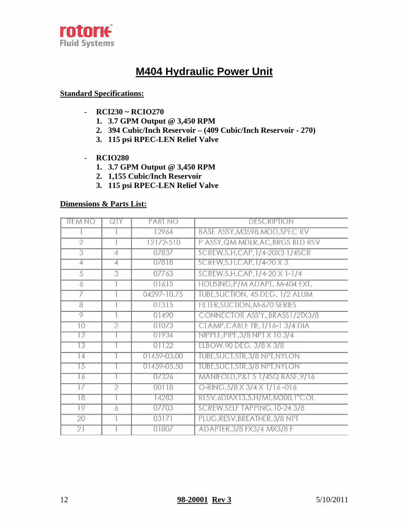
M404 Hydraulic Power Unit Standard Specifications:
- RCI230 ~ RCIO270 1. 3.7 GPM Output @ 3,450 RPM 2. 394 Cubic/Inch Reservoir – (409 Cubic/Inch Reservoir - 270) 3. 115 psi RPEC-LEN Relief Valve
- RCIO280
1. 3.7 GPM Output @ 3,450 RPM 2. 1,155 Cubic/Inch Reservoir 3. 115 psi RPEC-LEN Relief Valve
Dimensions & Parts List:

13 98-20001 Rev 3 5/10/2011
14 98-20001 Rev 3 5/10/2011
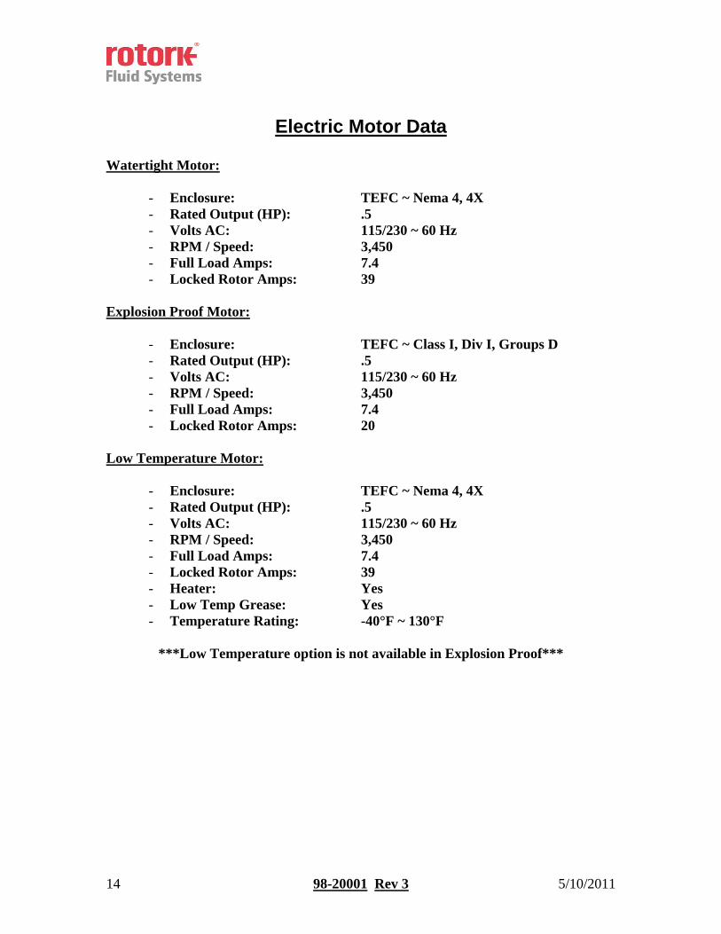
Electric Motor Data Watertight Motor:
- Enclosure: TEFC ~ Nema 4, 4X - Rated Output (HP): .5 - Volts AC: 115/230 ~ 60 Hz - RPM / Speed: 3,450 - Full Load Amps: 7.4 - Locked Rotor Amps: 39
Explosion Proof Motor:
- Enclosure: TEFC ~ Class I, Div I, Groups D - Rated Output (HP): .5 - Volts AC: 115/230 ~ 60 Hz - RPM / Speed: 3,450 - Full Load Amps: 7.4 - Locked Rotor Amps: 20
Low Temperature Motor:
- Enclosure: TEFC ~ Nema 4, 4X - Rated Output (HP): .5 - Volts AC: 115/230 ~ 60 Hz - RPM / Speed: 3,450 - Full Load Amps: 7.4 - Locked Rotor Amps: 39 - Heater: Yes - Low Temp Grease: Yes - Temperature Rating: -40°F ~ 130°F
***Low Temperature option is not available in Explosion Proof***
15 98-20001 Rev 3 5/10/2011
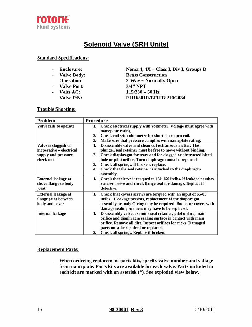
Solenoid Valve (SRH Units) Standard Specifications:
- Enclosure: Nema 4, 4X – Class I, Div I, Groups D - Valve Body: Brass Construction - Operation: 2-Way ~ Normally Open - Valve Port: 3/4” NPT - Volts AC: 115/230 – 60 Hz - Valve P/N: EH16801R/EFHT8210G034
Trouble Shooting: Problem Procedure Valve fails to operate 1. Check electrical supply with voltmeter. Voltage must agree with
nameplate rating. 2. Check coil with ohmmeter for shorted or open coil. 3. Make sure that pressure complies with nameplate rating.
Valve is sluggish or inoperative – electrical supply and pressure check out
1. Disassemble valve and clean out extraneous matter. The plunger/seal retainer must be free to move without binding.
2. Check diaphragm for tears and for clogged or obstructed bleed hole or pilot orifice. Torn diaphragm must be replaced.
3. Check all springs. If broken, replace. 4. Check that the seal retainer is attached to the diaphragm
assembly. External leakage at sleeve flange to body joint
1. Check that sleeve is torqued to 130-150 in/lbs. If leakage persists, remove sleeve and check flange seal for damage. Replace if defective.
External leakage at flange joint between body and cover
1. Check that covers screws are torqued with an input of 65-85 in/lbs. If leakage persists, replacement of the diaphragm assembly or body O-ring may be required. Bodies or covers with damage sealing surfaces may have to be replaced.
Internal leakage 1. Disassembly valve, examine seal retainer, pilot orifice, main orifice and diaphragm sealing surface in contact with main orifice. Remove all dirt. Inspect orifices for nicks. Damaged parts must be repaired or replaced.
2. Check all springs. Replace if broken. Replacement Parts:
- When ordering replacement parts kits, specify valve number and voltage
from nameplate. Parts kits are available for each valve. Parts included in each kit are marked with an asterisk (*). See exploded view below.

16 98-20001 Rev 3 5/10/2011
Exploded View (Solenoid)

17 98-20001 Rev 3 5/10/2011
Solenoid Valve (DAH Units)
Standard Specifications:
- Enclosure: Nema 4, 4X - Valve Body: Aluminum / Steel Construction - Operation: 4-Way ~ Normally Open - Valve Port: 3/8” NPT - Volts AC: 115/1/50 – 60 Hz - Valve P/N: AS19501R/DG038C115VAC72WB
Wiring: *Reference Only
Dimensions: Subplate
18 98-20001 Rev 3 5/10/2011
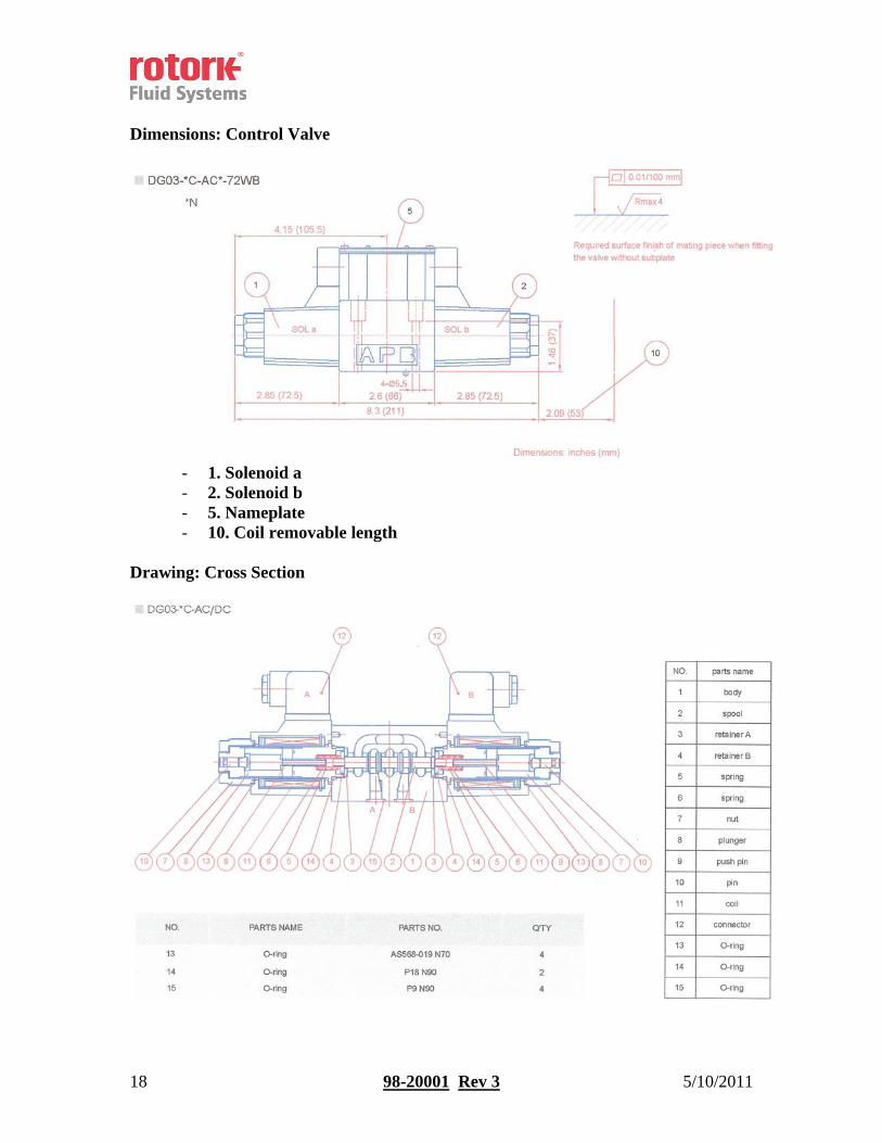
Dimensions: Control Valve
- 1. Solenoid a - 2. Solenoid b - 5. Nameplate - 10. Coil removable length
Drawing: Cross Section

19 98-20001 Rev 3 5/10/2011
2-Position Switch Box Standard Specifications:
- Enclosure: Nema 4, 4x – Class I, Div I, Group D - Limits Switches: (3) SPDT Mechanical Switches - Beacon: Yellow (Close) and Black (Open) - Conduit Entry: (1) ½” NPT - Part Number: EH16700R/S2007XNBY3SPDT
Field Calibration:
1. Operate the actuator to the full closed position. 2. Remove screws in Limit Switch housing, twist cover approximately
45° and lift straight up, see Figure 1. 3. To set Close position, lift bottom cam and turn until switch is
activated and then release. Spring will push cam back onto splined shaft, See Figure 2.
4. Operate the actuator to the opposite extreme. 5. To set Open position, push down on the middle cam and turn until the
open switch is activated. 6. To set Motor Shut off position, lift cam and turn until switch is
activated and then release. Motor shut off needs to be set opposite of fail position.
7. Operate actuator from one extreme to the other several times to check switch operation.
8. Replace housing cover. Confirm that you have noted the final position of the valve (full open or full close).
1. 2.

20 98-20001 Rev 3 5/10/2011
Modulating Switch Box
Standard Specifications:
- Enclosure: Nema 4, 4x – Class 1, Div. 1, Groups D - Limit Switches: (3) SPDT Mechanical Switches - Potentiometer: 1K Ohm - Beacon: Yellow (Close) and Black (Open) - Conduit Entry: (2) ¾” NPT - Part Number: EH16601R/DXP-MA1BNEB4607
Field Calibration:
*** Caution*** Never perform switch calibration while an area is known to be hazardous. Calibration procedures for DPDT switches are the same as those for SPDT
Switches.
Calibration may be performed using a Volt-Ohm meter by using the Ohm setting across COM and NO. When the switch is active, the meter will read <0.5 Ohms or the Diode setting may be used to indicate continuity. If 120 vac sources are used, an appropriately sized resistor must be used in series to limit current to a maximum of 15 Amperes when circuit rating is unknown, or permanent damage may occur. Auxiliary & Motor Shutoff Switch Calibration:
1. Operate the actuator to the full close position. 2. Remove screws in Limit Switch enclosure and remove cover. 3. With Valve in the Closed position, disengage the BOTTOM cam from the
splined Hub and rotate Clockwise until SW1 activates. Release cam to re-engage splined HUB.
4. Rotate valve to the OPEN position, disengage the TOP cam from the splined HUB and rotate Counter-clockwise until SW2 activates. Release cam to re-engage the splined Hub.
5. To set Motor Shut off position, disengage the MIDDLE cam from the Splined Hub and rotate Counter-clockwise until SW3 activates. Release cam to re-engage splined Hub. Motor Shut Off position needs to be set opposite of the fail position.
6. Cycle valve CLOSED and OPEN several times to insure switches will maintain calibration.
7. Using Ohmmeter, connect to terminal points 1 & 2 to measure the resistance value at the fail or start position.
21 98-20001 Rev 3 5/10/2011
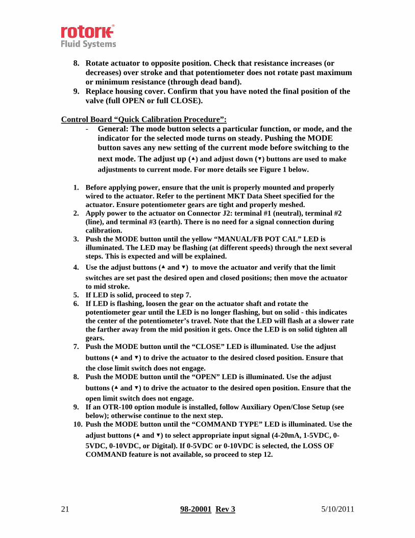
8. Rotate actuator to opposite position. Check that resistance increases (or
decreases) over stroke and that potentiometer does not rotate past maximum or minimum resistance (through dead band).
9. Replace housing cover. Confirm that you have noted the final position of the valve (full OPEN or full CLOSE).
Control Board “Quick Calibration Procedure”:
- General: The mode button selects a particular function, or mode, and the indicator for the selected mode turns on steady. Pushing the MODE button saves any new setting of the current mode before switching to the next mode. The adjust up (▲) and adjust down (▼) buttons are used to make adjustments to current mode. For more details see Figure 1 below.
1. Before applying power, ensure that the unit is properly mounted and properly
wired to the actuator. Refer to the pertinent MKT Data Sheet specified for the actuator. Ensure potentiometer gears are tight and properly meshed.
2. Apply power to the actuator on Connector J2: terminal #1 (neutral), terminal #2 (line), and terminal #3 (earth). There is no need for a signal connection during calibration.
3. Push the MODE button until the yellow “MANUAL/FB POT CAL” LED is illuminated. The LED may be flashing (at different speeds) through the next several steps. This is expected and will be explained.
4. Use the adjust buttons (▲ and ▼) to move the actuator and verify that the limit switches are set past the desired open and closed positions; then move the actuator to mid stroke.
5. If LED is solid, proceed to step 7. 6. If LED is flashing, loosen the gear on the actuator shaft and rotate the
potentiometer gear until the LED is no longer flashing, but on solid - this indicates the center of the potentiometer’s travel. Note that the LED will flash at a slower rate the farther away from the mid position it gets. Once the LED is on solid tighten all gears.
7. Push the MODE button until the “CLOSE” LED is illuminated. Use the adjust buttons (▲ and ▼) to drive the actuator to the desired closed position. Ensure that the close limit switch does not engage.
8. Push the MODE button until the “OPEN” LED is illuminated. Use the adjust buttons (▲ and ▼) to drive the actuator to the desired open position. Ensure that the open limit switch does not engage.
9. If an OTR-100 option module is installed, follow Auxiliary Open/Close Setup (see below); otherwise continue to the next step.
10. Push the MODE button until the “COMMAND TYPE” LED is illuminated. Use the adjust buttons (▲ and ▼) to select appropriate input signal (4-20mA, 1-5VDC, 0-5VDC, 0-10VDC, or Digital). If 0-5VDC or 0-10VDC is selected, the LOSS OF COMMAND feature is not available, so proceed to step 12.

22 98-20001 Rev 3 5/10/2011
11. Push the MODE button until the “LOSS OF COMMAND” LED is illuminated; this
sets the actuator to a predetermined position upon loss of command. Use the adjust buttons (▲ and ▼) to select appropriate position (OPEN, CLOSE, or LAST POSITION).
12. If an OTR-100 or OTX-100 option module is installed, follow Auxiliary Position Output Mode Setup (see below); otherwise continue to the next step.
13. Push the MODE button until the “AUTO” LED is illuminated. Your calibration is now COMPLETE. Connect the command signal wires to connector J2: terminal #4 (signal ground) and terminal #5 (mA input) OR terminal #6 (voltage input), depending on the application. If a signal input was already connected, the actuator should have moved to that position.
Auxiliary Open/Close Setup:
- For units with an OTR-100 Feedback option module only.
1. Push the MODE button until the “AUX CLOSE OUTPUT” LED is illuminated. Use the adjust buttons (▲ and ▼) to drive the actuator to the desired auxiliary close position.
2. Push the MODE button until the “AUX OPEN OUTPUT” LED is on. Use the adjust buttons (▲ and ▼) to drive the actuator to the desired auxiliary open position.
3. Continue with Step 10 in the Quick Calibration Procedure (see above). Auxiliary Position Output Mode Setup:
- For units with an OTR-100 or OTX-100 Feedback option module only.
1. Push the MODE button until the red “AUX POSITION OUT CAL” LED illuminates while the “CLOSE” LED flashes. Note that the red LED flashes to indicate a “Fault” and turns on steady to indicate the "AUX POSITION OUT CAL" modes.
2. Use the adjust buttons (▲ and ▼) to set the desired output voltage or current (mA) on the option module output for the closed position.
3. Push the MODE button so the “AUX POSITION OUT CAL” LED remains steady while the “OPEN” LED flashes. Use the adjust buttons (▲ and ▼) to set the desired output voltage or current (mA) on the option module output for the open position.
4. Continue with Step 13 in the Quick Calibration Procedure (see above). Figure 1:
23 98-20001 Rev 3 5/10/2011
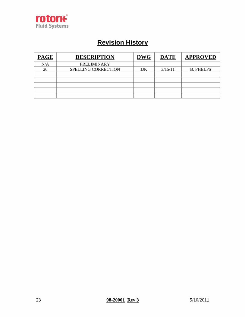
Revision History
PAGE DESCRIPTION DWG DATE APPROVED N/A PRELIMINARY 20 SPELLING CORRECTION JJK 3/15/11 B. PHELPS


