17
ROUGH REPORT VARIABLE VALVE TIMING 16/8/2011 Submitted by, Roshan George Koshy Roll no: 13 S 2 , M.Tech. (ICTM) GEC Thrissur
ROUGH REPORT
VARIABLE VALVE TIMING
16/8/2011
Submitted by,
Roshan George Koshy
Roll no: 13
S2, M.Tech. (ICTM)
GEC Thrissur

Variable Valve Timing
1
ABSTRACT
Until recently, an automobile manufacturer used one or more camshafts (plus some pushrods,
lifters and rocker arms) to open and close an engine's valves. The camshaft/camshafts was
turned by a timing chain that connected to the crankshaft. As engine rpm's rose and fell, the
crankshaft and camshaft would turn faster or slower to keep valve timing relatively close to
what was needed for engine operation. Unfortunately, the dynamics of airflow through a
combustion chamber change radically between 2,000 rpm and 6,000 rpm. Despite the
manufacturer's best efforts, there was just no way to maximize valve timing for high and low
rpm with a simple crankshaft-driven valve train. Instead, engineers had to develop a
"compromise" system that would allow an engine to start and run when pulling out of the
driveway but also allow for strong acceleration and highway cruising at 70+ mph. Obviously,
they were successful. However, because of the "compromise" nature of standard valve train
systems, few engines were ever in their "sweet zone," which resulted in wasted fuel and
reduced performance. Variable valve timing has changed all that. By coming up with a way
to alter valve timing between high and low rpm's, Honda, Toyota and BMW and many more
manufacturer's can now tune valve operation for optimum performance and efficiency
throughout the entire rev range.

Variable Valve Timing
2
INTRODUCTION
Engine breathing is analogous to the breathing of any living organism. At rest, the lungs take
in the necessary amount of air for normal function. When running, the lungs and heart work
faster to supply more oxygen to the system. Engines can't do that because their breathing
apparatus (comprised intake manifolds, intake runners, valves, valve lift and throttle bores) is
fixed.
There was a time when engines had to be big to be powerful. There was a time when engines
could either be tuned for low-rpm torque or high-rpm power, but not both. There was a time
was a time when a specific output of 100 hp per liter was the stuff of racecar fantasies. Today
these limitations are all but gone. Getting 100 hp for each liter of displacement is now
possible on cars that have to get good gas mileage, emit clean air, act civilized enough for
your grandmother to drive them and sell for under $20,000
Remember that an engine is basically a glorified air pump and, as such, the most effective
way to increase horsepower and/or efficiency is to increase an engine's ability to process air.
There are a number of ways to do this that range from altering the exhaust system to
upgrading the fuel system to installing a less-restrictive air filter. Since an engine's valves
play a major role in how air gets in and out of the combustion chamber, it makes sense to
focus on them when looking to increase horsepower and efficiency. This is exactly what
Honda, Toyota and BMW and quite a number of other manufacturer's have done in recent
years.
Popet values are used in gasoline and diesel engines to control the inlet and exhaust of air
passing through the engine. When the intake values open, air is drawn into the engine
cylinder. After the fuel has been burnt, the exhaust valves then open to let it leave. In
conventional engines, the popet valves open and close at a constant speed. Their timings do
not depend on how fast the engine is running. At high engine speeds [e.g. when overtaking a
slower vehicle], this starts to become a problem. Large amounts of air are required by the
engine at higher speeds. However, the intake valves may close before all the air has been
given a chance to flow in. On the other hand, if the valves were calibrated to remain open for
longer periods of time, problems start to occur at the lower engine speeds. In these situations,
unburnt fuel may exit from the engine since the valves are still open. This leads to lower

Variable Valve Timing
3
engine performance and increased emissions. By using advanced systems to alter the opening
and closing of engine valves, they have created more powerful and clean burning engines
that require less fuel and are relatively small in displacement.
DEVELOPMENT OF VVT TECHNOLOGY
Honda broke the ice when the NSX debuted in 1991 as the first production car with a
variable valve timing system. Honda's VTEC (which sort of stands for Variable valve Timing
and lift Electronic Control) system, which has basically remained unchanged since then, is
still one of the most effective systems for making ultra high specific output. Ferrari has a
really neat way of doing this. The camshafts on some Ferrari engines are cut with a three-
dimensional profile that varies along the length of the cam lobe. At one end of the cam lobe
is the least aggressive cam profile, and at the other end is the most aggressive. The shape of
the cam smoothly blends these two profiles together. A mechanism can slide the whole
camshaft laterally so that the valve engages different parts of the cam. The shaft still spins
just like a regular camshaft, but by gradually sliding the camshaft laterally as the engine
speed and load increase, the valve timing can be optimized.
TYPES OF VVT
Honda VTEC
The concept is incredibly simple. So simple, in fact, that you have to wonder why nobody
thought of it earlier. Basically each pair of valves has three cam lobes, two that operate the
valves at low-rpm, and a third that takes over at high rpm. During low-rpm operation, the two
rocker arms riding the low-rpm lobes push directly on the top of the valves. In most cases,
the cam profiles of the two intake valves will be slightly different, promoting swirl in the
combustion chamber for better drivability. At high rpm (usually 4500 rpm to 6500 rpm
range, depending on the engine) the ECU sends a signal to an oil control valve that allows oil
pressure to flow into the low-rpm rocker arms. A third, high rpm rocker arm sits between the
two low-rpm arms and follows a much more aggressive lobe.
Variable Valve Timing
4
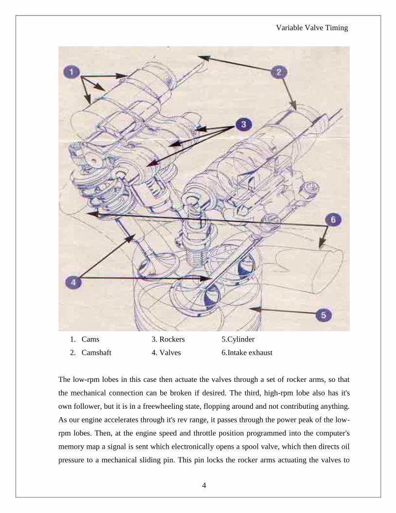
1. Cams 3. Rockers 5.Cylinder
2. Camshaft 4. Valves 6.Intake exhaust
The low-rpm lobes in this case then actuate the valves through a set of rocker arms, so that
the mechanical connection can be broken if desired. The third, high-rpm lobe also has it's
own follower, but it is in a freewheeling state, flopping around and not contributing anything.
As our engine accelerates through it's rev range, it passes through the power peak of the low-
rpm lobes. Then, at the engine speed and throttle position programmed into the computer's
memory map a signal is sent which electronically opens a spool valve, which then directs oil
pressure to a mechanical sliding pin. This pin locks the rocker arms actuating the valves to
Variable Valve Timing
5
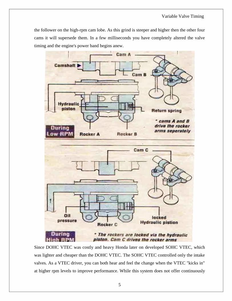
the follower on the high-rpm cam lobe. As this grind is steeper and higher then the other four
cams it will supersede them. In a few milliseconds you have completely altered the valve
timing and the engine's power band begins anew.
Since DOHC VTEC was costly and heavy Honda later on developed SOHC VTEC, which
was lighter and cheaper than the DOHC VTEC. The SOHC VTEC controlled only the intake
valves. As a VTEC driver, you can both hear and feel the change when the VTEC "kicks in"
at higher rpm levels to improve performance. While this system does not offer continuously
Variable Valve Timing
6
variable valve timing, it can make the most of high rpm operation while still providing solid
drivability at lower rpm levels. Honda is already working on a three-step VTEC system that
will further improve performance and efficiency across the engine rpm range. The camshaft
in a pushrod engine is often driven by gears or a short chain.
Toyota VVT-i
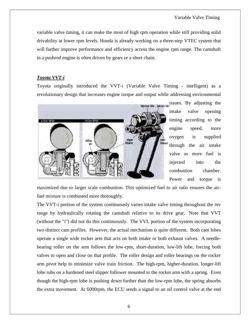
Toyota originally introduced the VVT-i (Variable Valve Timing - intelligent) as a
revolutionary design that increases engine torque and output while addressing environmental
issues. By adjusting the
intake valve opening
timing according to the
engine speed, more
oxygen is supplied
through the air intake
valve as more fuel is
injected into the
combustion chamber.
Power and torque is
maximized due to larger scale combustion. This optimized fuel to air ratio ensures the air-
fuel mixture is combusted more thoroughly.
The VVT-i portion of the system continuously varies intake valve timing throughout the rev
range by hydraulically rotating the camshaft relative to its drive gear. Note that VVT
(without the "i") did not do this continuously. The VVL portion of the system incorporating
two distinct cam profiles. However, the actual mechanism is quite different. Both cam lobes
operate a single wide rocker arm that acts on both intake or both exhaust valves. A needle-
bearing roller on the arm follows the low-rpm, short-duration, low-lift lobe, forcing both
valves to open and close on that profile. The roller design and roller bearings on the rocker
arm pivot help to minimize valve train friction. The high-rpm, higher-duration, longer-lift
lobe rubs on a hardened steel slipper follower mounted to the rocker arm with a spring. Even
though the high-rpm lobe is pushing down further than the low-rpm lobe, the spring absorbs
the extra movement. At 6000rpm, the ECU sends a signal to an oil control valve at the end

Variable Valve Timing
7
of the camshaft that puts oil pressure behind a lock pin in the rocker arm, sliding the pin
under the spring-loaded slipper follower, locking it to the rocker arm and forcing the arm to
follow the high-rpm cam profile.
Toyota's newest version of VVT-i is also quite simple, though it may look otherwise on
initial inspection. Again, the exhaust cam is driven from the crank, while the intake cam is
driven off the exhaust cam. This time, the drive is via gears, and a mysterious cylinder
behind the drive gear on intake cam controls cam timing. Inside this mysterious cylinder is a
simple three-fluted rotor that actually drives the cam. By pumping oil into the chambers on
either side of the three flutes, the hydraulic pressure can force the cam to advance or retard.
This replaces the previous VVT-i system, which was basically an incomprehensible little box
of gears, springs and splines.
The VVT-i system can change the intake cam timing over a 60 degree range, changing valve
overlap from absolutely zero (for smooth idle, easy starting and better cold start
performance), to severely overlapped for a natural EGR effect at medium load (eliminating

Variable Valve Timing
8
the need for an Exhaust Gas Recirculation valve), to whatever is ideal for maximum power at
any point on the powerband.
Porsche’s VARIOCAM
Porsche's VarioCam, used first on the 968 and know used without the fanfare on all (both) of
their engines is as simple as it gets. With VarioCam, the crank drives the exhaust cam, and
the intake cam is driven, via a short
chain, by the exhaust cam. In order to
advance and retard the intake cam,
the chain tensioner on that short
chain simply shifts up and down,
moving the extra length in the chain
from the tight side to the slack side.
When the tight side has no extra
chain (i.e. the chain is straight), the
intake cam is fully advanced, as more
chain is shifted to the tight side, the
cam is retarded.
Ferrari’ Cam Advance Mechanism
Ferrari has a really neat way of doing this. The camshafts on some Ferrari engines are cut
with a three-dimensional profile that varies along the length of the cam lobe. At one end of
the cam lobe is the least aggressive cam profile, and at the other end is the most aggressive.
The shape of the cam smoothly blends these two profiles together. A mechanism can slide
the whole camshaft laterally so that the valve engages different parts of the cam. The shaft
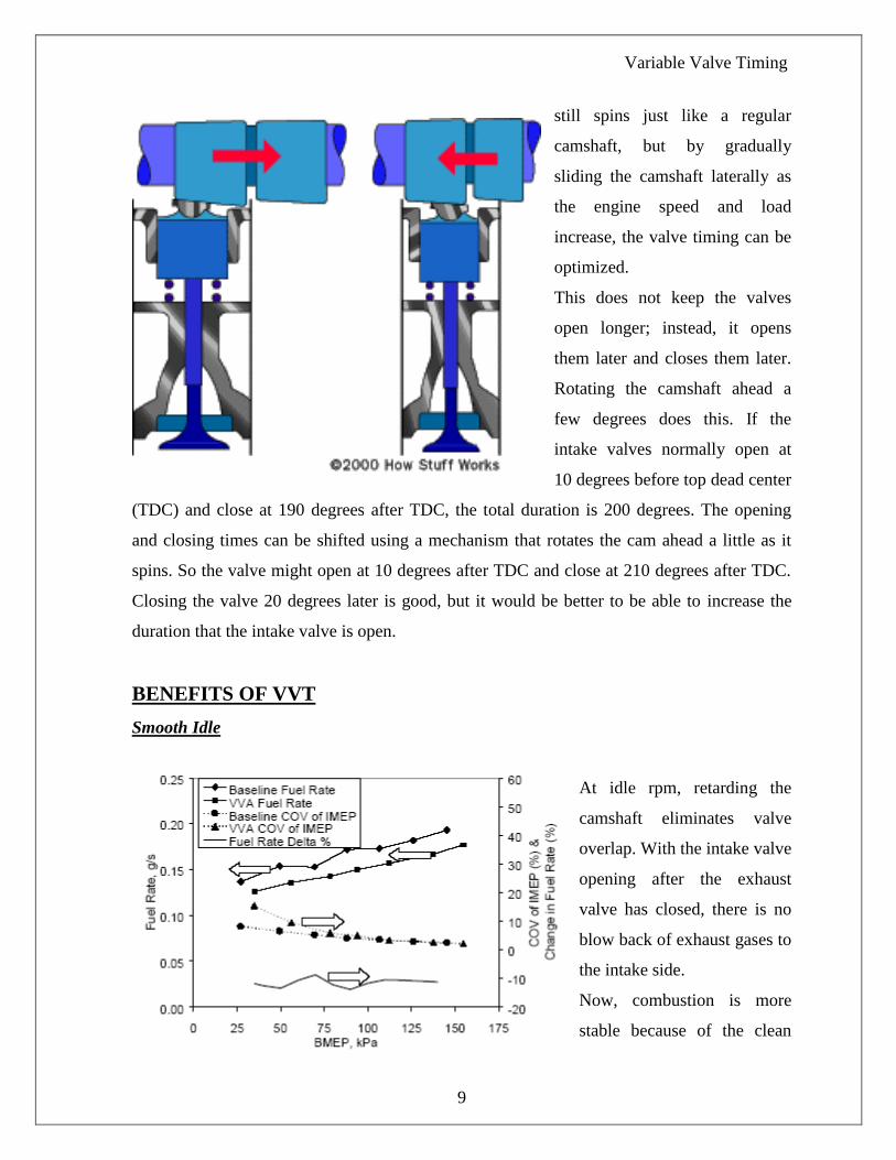
Variable Valve Timing
9
still spins just like a regular
camshaft, but by gradually
sliding the camshaft laterally as
the engine speed and load
increase, the valve timing can be
optimized.
This does not keep the valves
open longer; instead, it opens
them later and closes them later.
Rotating the camshaft ahead a
few degrees does this. If the
intake valves normally open at
10 degrees before top dead center
(TDC) and close at 190 degrees after TDC, the total duration is 200 degrees. The opening
and closing times can be shifted using a mechanism that rotates the cam ahead a little as it
spins. So the valve might open at 10 degrees after TDC and close at 210 degrees after TDC.
Closing the valve 20 degrees later is good, but it would be better to be able to increase the
duration that the intake valve is open.
BENEFITS OF VVT
Smooth Idle
At idle rpm, retarding the
camshaft eliminates valve
overlap. With the intake valve
opening after the exhaust
valve has closed, there is no
blow back of exhaust gases to
the intake side.
Now, combustion is more
stable because of the clean
Variable Valve Timing
10
air/fuel mixture. This allows the engine idle smoothly at a lower rpm and fuel consumption is
reduced.
Torque Improvement in Low to Medium Speed Range
In the low to medium speed
range with a heavy load, the
camshaft is advanced
increasing the valve overlap.
This has two effects. First,
the exhaust gases help pull
in the intake mixture.
Second, by closing the
intake valve early, the
air/fuel mixture taken into the cylinder is not discharged. This improves volumetric
efficiency and increases torque (and therefore horsepower) in the low and midrange rpm
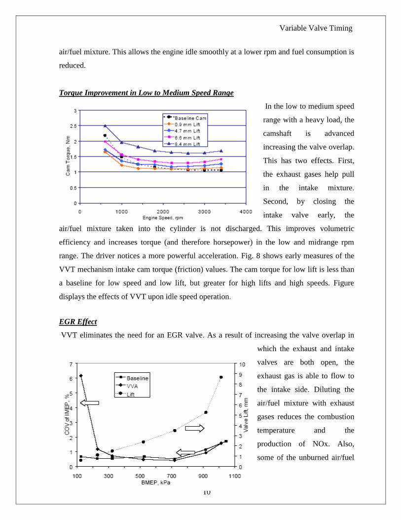
range. The driver notices a more powerful acceleration. Fig. 8 shows early measures of the
VVT mechanism intake cam torque (friction) values. The cam torque for low lift is less than
a baseline for low speed and low lift, but greater for high lifts and high speeds. Figure
displays the effects of VVT upon idle speed operation.
EGR Effect
VVT eliminates the need for an EGR valve. As a result of increasing the valve overlap in
which the exhaust and intake
valves are both open, the
exhaust gas is able to flow to
the intake side. Diluting the
air/fuel mixture with exhaust
gases reduces the combustion
temperature and the
production of NOx. Also,
some of the unburned air/fuel
Variable Valve Timing
11
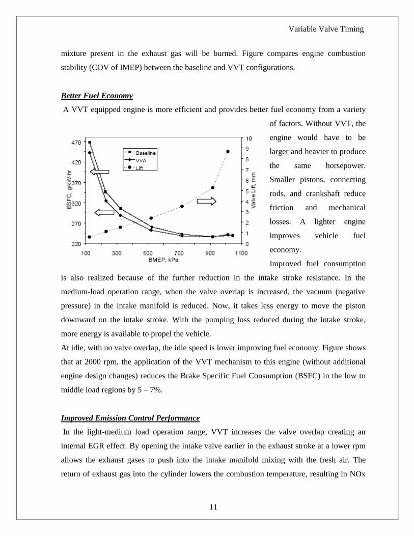
mixture present in the exhaust gas will be burned. Figure compares engine combustion
stability (COV of IMEP) between the baseline and VVT configurations.
Better Fuel Economy
A VVT equipped engine is more efficient and provides better fuel economy from a variety
of factors. Without VVT, the
engine would have to be
larger and heavier to produce
the same horsepower.
Smaller pistons, connecting
rods, and crankshaft reduce
friction and mechanical
losses. A lighter engine
improves vehicle fuel
economy.
Improved fuel consumption
is also realized because of the further reduction in the intake stroke resistance. In the
medium-load operation range, when the valve overlap is increased, the vacuum (negative
pressure) in the intake manifold is reduced. Now, it takes less energy to move the piston
downward on the intake stroke. With the pumping loss reduced during the intake stroke,
more energy is available to propel the vehicle.
At idle, with no valve overlap, the idle speed is lower improving fuel economy. Figure shows
that at 2000 rpm, the application of the VVT mechanism to this engine (without additional
engine design changes) reduces the Brake Specific Fuel Consumption (BSFC) in the low to
middle load regions by 5 – 7%.
Improved Emission Control Performance
In the light-medium load operation range, VVT increases the valve overlap creating an
internal EGR effect. By opening the intake valve earlier in the exhaust stroke at a lower rpm
allows the exhaust gases to push into the intake manifold mixing with the fresh air. The
return of exhaust gas into the cylinder lowers the combustion temperature, resulting in NOx

Variable Valve Timing
12
reduction. Essentially, VVT will increase the valve overlap to obtain the same EGR effect as
an engine equipped with an EGR valve. In other words, when an EGR valve on an EGR
equipped engine opens is when VVT will increase the valve overlap.
Another benefit is that HCs
are also reduced. Some of
the unburned air/fuel
mixture from the previous
cycle returns to the
cylinder for combustion.
Finally, C02 is reduced
because of the decrease in
fuel consumption. Figure
presents engine-out HC
and NOx specific emissions at 2000 engine rpm.
THE FUTURE
If all this exotic variable valve timing technology is commonplace now, what does the future
hold? Currently we are limited to either adjusting overlap by moving a standard camshaft, or
switching between two fixed cam profiles. There is no reason (other then cost) why both
systems could not be used in parallel on one engine, but the benefits may be limited. The true
future of variable valve timing is infinite adjustability of both lift and timing.
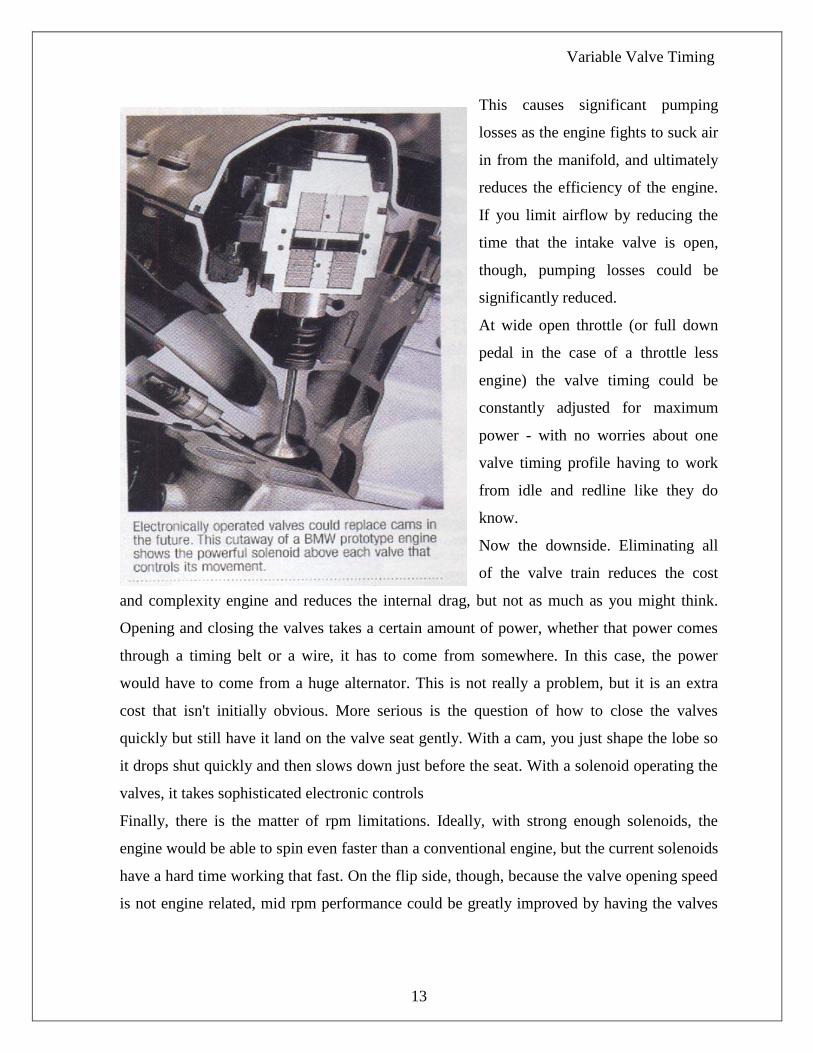
The idea of opening and closing the valves with large electrical solenoids has been bounced
around for several years. Many different manufacturers from Cummins to BMW have
proposed such systems, and even made running prototypes. There are a few problems with
electronically operated valves, but let's look at the advantages first. Current gasoline engines
control part throttle airflow via a throttle plate, essentially lowering the air pressure in the
intake manifold by choking it off with a partially closed throttle plate.
Variable Valve Timing
13
This causes significant pumping
losses as the engine fights to suck air
in from the manifold, and ultimately
reduces the efficiency of the engine.
If you limit airflow by reducing the
time that the intake valve is open,
though, pumping losses could be
significantly reduced.
At wide open throttle (or full down
pedal in the case of a throttle less
engine) the valve timing could be
constantly adjusted for maximum
power - with no worries about one
valve timing profile having to work
from idle and redline like they do
know.
Now the downside. Eliminating all
of the valve train reduces the cost
and complexity engine and reduces the internal drag, but not as much as you might think.
Opening and closing the valves takes a certain amount of power, whether that power comes
through a timing belt or a wire, it has to come from somewhere. In this case, the power
would have to come from a huge alternator. This is not really a problem, but it is an extra
cost that isn't initially obvious. More serious is the question of how to close the valves
quickly but still have it land on the valve seat gently. With a cam, you just shape the lobe so
it drops shut quickly and then slows down just before the seat. With a solenoid operating the
valves, it takes sophisticated electronic controls
Finally, there is the matter of rpm limitations. Ideally, with strong enough solenoids, the
engine would be able to spin even faster than a conventional engine, but the current solenoids
have a hard time working that fast. On the flip side, though, because the valve opening speed
is not engine related, mid rpm performance could be greatly improved by having the valves

Variable Valve Timing
14
slam to full open much faster than a conventional valvetrain, improving volumetric
efficiency and making more power.
Finally, BMW has actually designed a mechanical system that still uses conventional cam
lobes, but is still able to vary lift and timing by moving the fulcrum point of the rocker arm.
The system is incredibly difficult to visualize, but it could offer most of the advantages of
electrically actuated valves without delving so far into unexplored technologies.
With the current variable timing technologies, the 100 hp per liter hurdle has been cleared.
Honda, in particular, has knocked the hurdle over and stomped it into the ground. With the
technologies on their way, 150 hp per litre is on the horizon.
Variable Valve Timing
15
CONCLUSION
So after this seminar we come to know that VVT technology is going to become prominent
in road cars as this technology is going to be researched a lot and may be in few years its cost
of production can be brought down to incredible levels. We already kwon about the benefits
of such a system and there should not be anyone who dislikes this technology, since in
today’s eco-friendly world this technology brings a ray of hope for a cleaner and healthier
environment. Already the automobile giants like Honda, Toyota, BMW, Mercedes-Benz, etc.
are spending lots of money on research in this field. So VVT technology is bound to have a
bright future in the automobile industry.

Variable Valve Timing
16
REFERENCES
1. “Design and Development of a Mechanical Variable Valve Actuation System”,
Ronald J. Pierik & James F. Burkhard, Delphi Automotive Systems, SAE Technical
Paper 2000-01-1221
2. “Variable Valve Timing”, Karl Brauer, Vision Engineer
3. www.wabashtech.com
4. www.delphi.com
5. www.madsci.org
6. www.toyotamotors.com
7. Ovedrive March 2003
8. Autocar December 2003


