312
© 2007 – 2010, Cisco Systems, Inc. All rights reserved. Cisco Public ROUTE v6 Chapter 8 1 Chapter 8: Implementing IPv6 in the Enterprise Network CCNP ROUTE: Implementing IP Routing
© 2007 – 2010, Cisco Systems, Inc. All rights reserved. Cisco Public
ROUTE v6 Chapter 81
Chapter 8: Implementing IPv6 in the Enterprise Network
CCNP ROUTE: Implementing IP Routing
Chapter 82© 2007 – 2010, Cisco Systems, Inc. All rights reserved. Cisco Public
Chapter 8 Objectives
Describe IPv6.
Describe the basics of IPv6 addressing.
Describe and configure IPv6 addresses.
Describe and configure IPv6 routing.
Describe and configure IPv6 tunneling.
Describe and configure static and dynamic NAT-PT.

Chapter 83© 2007 – 2010, Cisco Systems, Inc. All rights reserved. Cisco Public
Introducing IPv6
Chapter 84© 2007 – 2010, Cisco Systems, Inc. All rights reserved. Cisco Public
Introducing IPv6
The ability to scale networks for future demands requires a
limitless supply of IP addresses and improved mobility.
• IPv6 combines expanded addressing with a more efficient and
feature-rich header to meet these demands.
• While it has many similarities to IPv4, IPv6 satisfies the increasingly
complex requirements of hierarchical addressing that IPv4 does not
support.

Chapter 85© 2007 – 2010, Cisco Systems, Inc. All rights reserved. Cisco Public
The Internet Is Growing …
In 2009, only 21% of the world population were connected.
• This adoption rate will increase as underdeveloped countries get
connected.
Chapter 86© 2007 – 2010, Cisco Systems, Inc. All rights reserved. Cisco Public
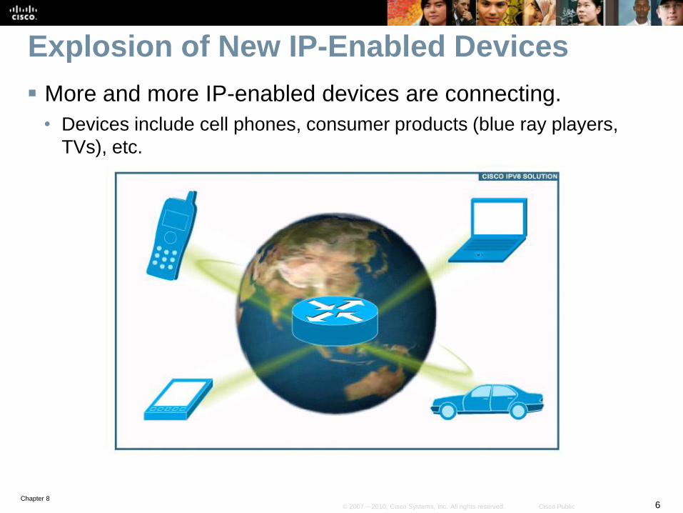
Explosion of New IP-Enabled Devices
More and more IP-enabled devices are connecting.
• Devices include cell phones, consumer products (blue ray players,
TVs), etc.
Chapter 87© 2007 – 2010, Cisco Systems, Inc. All rights reserved. Cisco Public
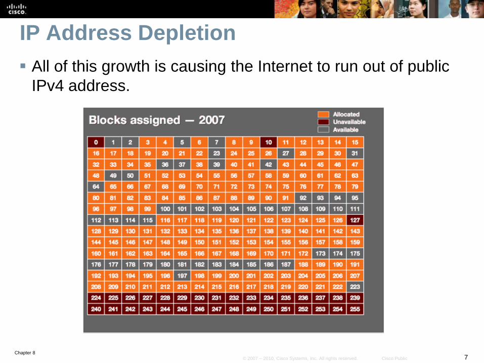
IP Address Depletion
All of this growth is causing the Internet to run out of public
IPv4 address.
Chapter 88© 2007 – 2010, Cisco Systems, Inc. All rights reserved. Cisco Public
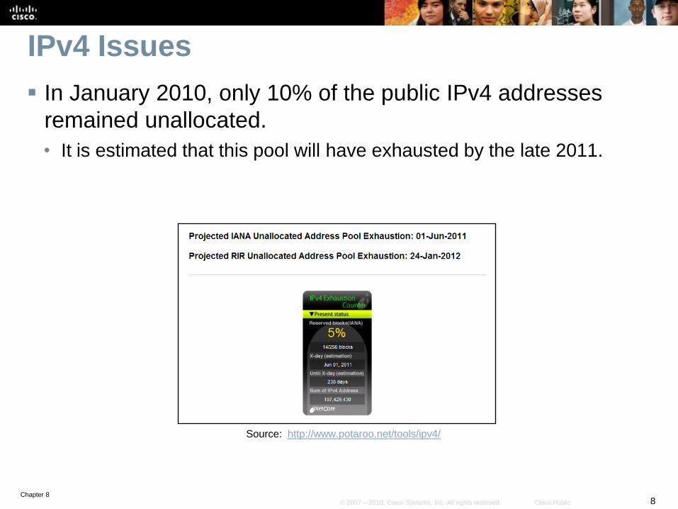
IPv4 Issues
In January 2010, only 10% of the public IPv4 addresses
remained unallocated.
• It is estimated that this pool will have exhausted by the late 2011.
Source: http://www.potaroo.net/tools/ipv4/
Chapter 89© 2007 – 2010, Cisco Systems, Inc. All rights reserved. Cisco Public
Other IPv4 Issues
Internet routing table expansion
• The Internet routing tables continue to grow which means Internet
core routers require more processing power, memory, and overhead.
Lack of true end-to-end model
• IPv4 networks typically use NAT as the solution to address depletion.
• However, NAT hides the true source address of traffic, which can
cause other issues.
Chapter 810© 2007 – 2010, Cisco Systems, Inc. All rights reserved. Cisco Public
Features of IPv6
Larger address space
• IPv6 addresses are 128 bits, compared to IPv4’s 32 bits.
• There are enough IPv6 addresses to allocate more than the entire IPv4
Internet address space to everyone on the planet.
Elimination of public-to-private NAT
• End-to-end communication traceability is possible.
Elimination of broadcast addresses
• IPv6 now includes unicast, multicast, and anycast addresses.
Support for mobility and security
• Helps ensure compliance with mobile IP and IPsec standards.
Simplified header for improved router efficiency
Chapter 811© 2007 – 2010, Cisco Systems, Inc. All rights reserved. Cisco Public
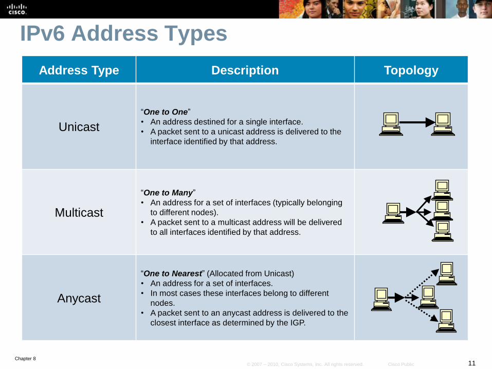
IPv6 Address Types
Address Type Description Topology
Unicast
“One to One”
• An address destined for a single interface.
• A packet sent to a unicast address is delivered to the
interface identified by that address.
Multicast
“One to Many”
• An address for a set of interfaces (typically belonging
to different nodes).
• A packet sent to a multicast address will be delivered
to all interfaces identified by that address.
Anycast
“One to Nearest” (Allocated from Unicast)
• An address for a set of interfaces.
• In most cases these interfaces belong to different
nodes.
• A packet sent to an anycast address is delivered to the
closest interface as determined by the IGP.
Chapter 812© 2007 – 2010, Cisco Systems, Inc. All rights reserved. Cisco Public
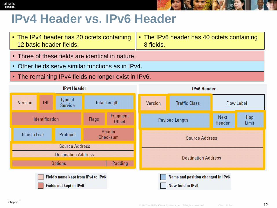
IPv4 Header vs. IPv6 Header
• The IPv4 header has 20 octets containing
12 basic header fields.
• The IPv6 header has 40 octets containing
8 fields.
• Three of these fields are identical in nature.
• Other fields serve similar functions as in IPv4.
• The remaining IPv4 fields no longer exist in IPv6.
Chapter 813© 2007 – 2010, Cisco Systems, Inc. All rights reserved. Cisco Public
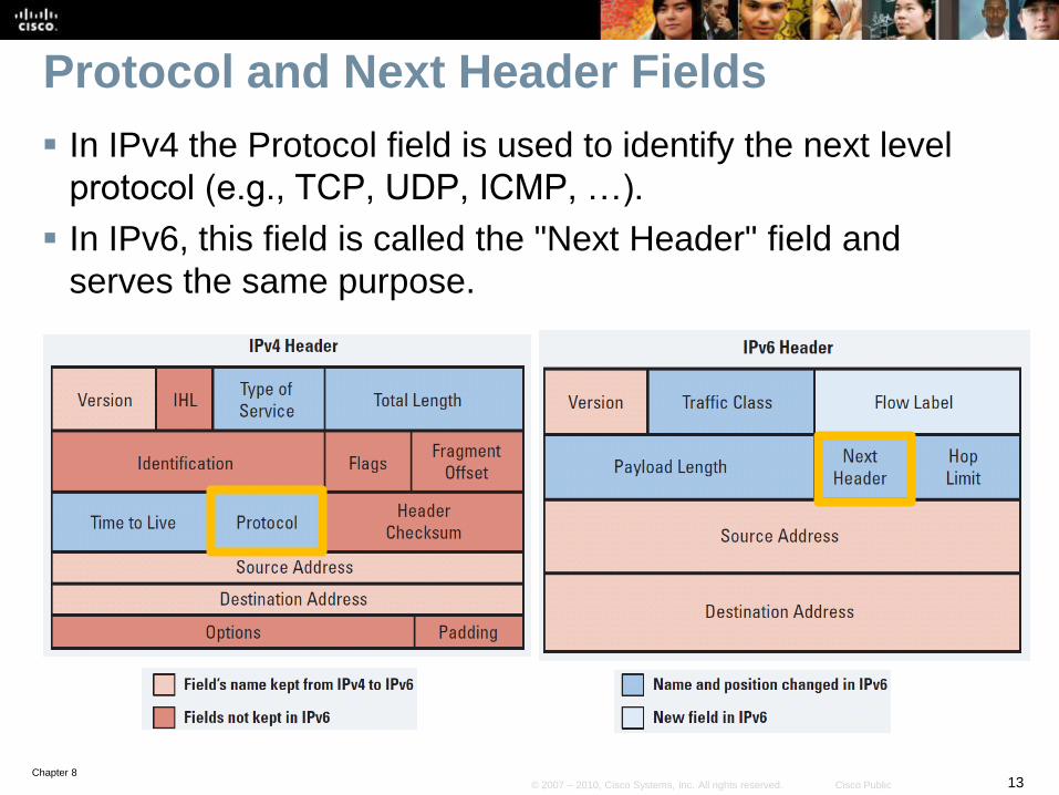
Protocol and Next Header Fields
In IPv4 the Protocol field is used to identify the next level
protocol (e.g., TCP, UDP, ICMP, …).
In IPv6, this field is called the "Next Header" field and
serves the same purpose.
Chapter 814© 2007 – 2010, Cisco Systems, Inc. All rights reserved. Cisco Public
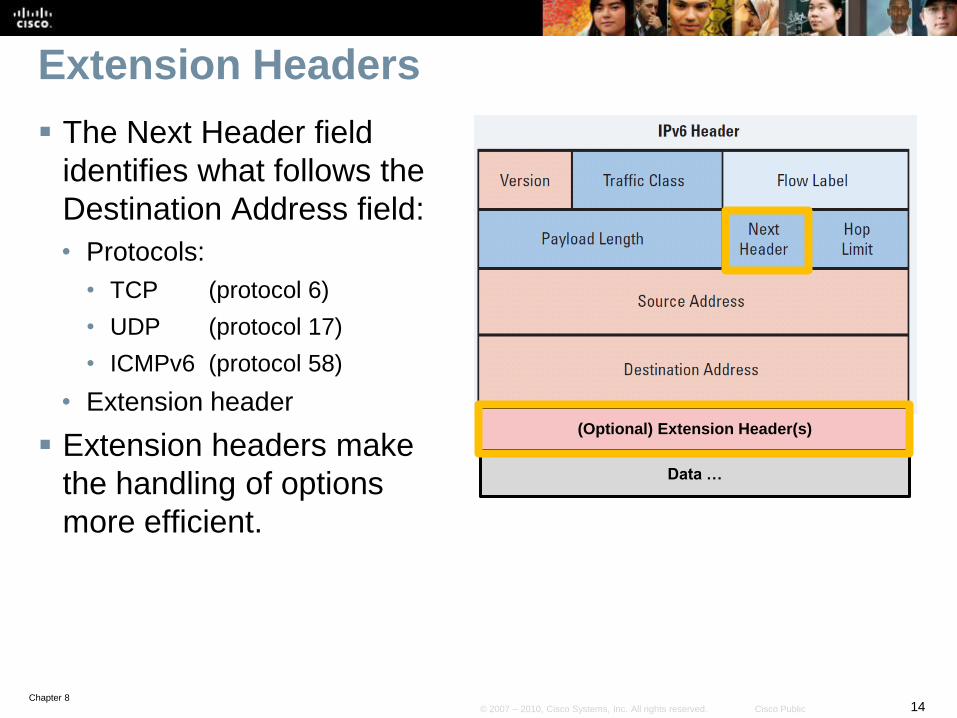
Extension Headers
The Next Header field
identifies what follows the
Destination Address field:
• Protocols:
• TCP (protocol 6)
• UDP (protocol 17)
• ICMPv6 (protocol 58)
• Extension header
Extension headers make
the handling of options
more efficient.
(Optional) Extension Header(s)
Data …
Chapter 815© 2007 – 2010, Cisco Systems, Inc. All rights reserved. Cisco Public
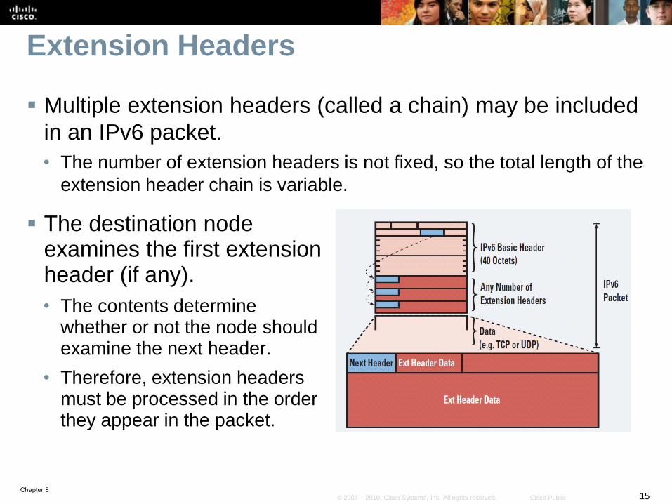
Extension Headers
Multiple extension headers (called a chain) may be included
in an IPv6 packet.
• The number of extension headers is not fixed, so the total length of the
extension header chain is variable.
The destination node examines the first extension header (if any).
• The contents determine whether or not the node should examine the next header.
• Therefore, extension headers must be processed in the order they appear in the packet.
Chapter 816© 2007 – 2010, Cisco Systems, Inc. All rights reserved. Cisco Public
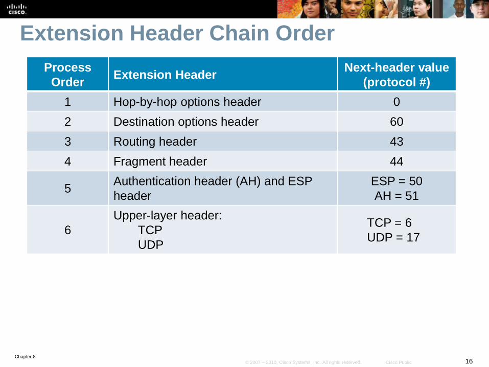
Extension Header Chain Order
Process
OrderExtension Header
Next-header value
(protocol #)
1 Hop-by-hop options header 0
2 Destination options header 60
3 Routing header 43
4 Fragment header 44
5Authentication header (AH) and ESP
header
ESP = 50
AH = 51
6
Upper-layer header:
TCP
UDP
TCP = 6
UDP = 17
Chapter 817© 2007 – 2010, Cisco Systems, Inc. All rights reserved. Cisco Public
MTU Discovery
IPv6 routers no longer perform fragmentation.
A discovery process is used to determine the optimum MTU
to use during a given session.
• In this discovery process, the source IPv6 device attempts to send a
packet at the size that is specified by the upper IP layers, for example,
the transport and application layers.
If the device receives an Internet Control Message Protocol
(ICMP) “packet too big” message, it retransmits the MTU
discover packet with a smaller MTU; this process is
repeated until the device receives a response that the
discover packet arrived intact.
The device then sets the MTU for the session.
Chapter 818© 2007 – 2010, Cisco Systems, Inc. All rights reserved. Cisco Public
New IPv6 Features
Prefix renumbering
• IPv6 allows simplified mechanisms for address and prefix
renumbering.
Multiple addresses per interface
• An IPv6 interface can have multiple addresses.
Link-local addresses
• IPv6 link-local addresses are used as the next hop when IGPs are
exchanging routing updates.
Stateless autoconfiguration:
• DHCP is not required because an IPv6 device can automatically
assign itself a unique IPv6 link-local address.
Provider-dependent or provider-independent
addressing
Chapter 819© 2007 – 2010, Cisco Systems, Inc. All rights reserved. Cisco Public
Is IPv4 Obsolete?
IPv4 is in no danger of disappearing overnight.
• It will coexist with IPv6 and then gradually be replaced.
IPv6 provides many transition options including:
• Dual stack:
• Both IPv4 and IPv6 are configured and run simultaneously on the interface.
• IPv6-to-IPv4 (6to4) tunneling and IPv4-compatible tunneling.
• NAT protocol translation (NAT-PT) between IPv6 and IPv4.
Chapter 820© 2007 – 2010, Cisco Systems, Inc. All rights reserved. Cisco Public
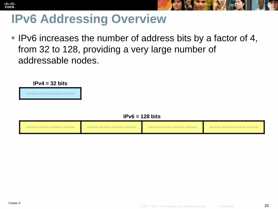
IPv6 Addressing Overview
IPv6 increases the number of address bits by a factor of 4,
from 32 to 128, providing a very large number of
addressable nodes.
IPv4 = 32 bits
11111111.11111111.11111111.11111111
IPv6 = 128 bits
11111111.11111111.11111111.11111111 11111111.11111111.11111111.11111111 11111111.11111111.11111111.11111111 11111111.11111111.11111111.11111111
Chapter 821© 2007 – 2010, Cisco Systems, Inc. All rights reserved. Cisco Public
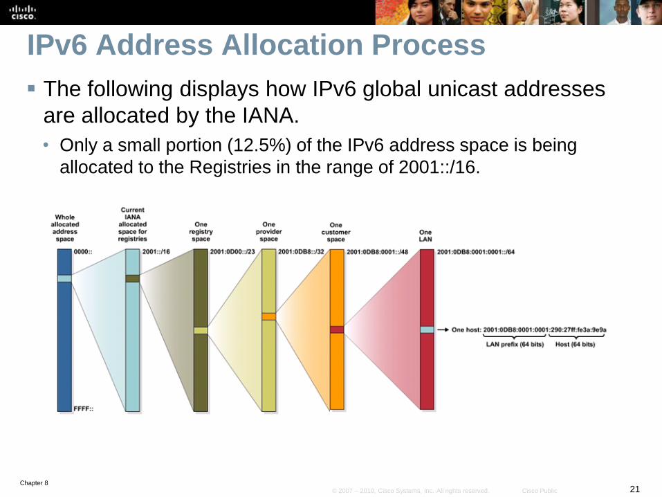
IPv6 Address Allocation Process
The following displays how IPv6 global unicast addresses
are allocated by the IANA.
• Only a small portion (12.5%) of the IPv6 address space is being
allocated to the Registries in the range of 2001::/16.
Chapter 822© 2007 – 2010, Cisco Systems, Inc. All rights reserved. Cisco Public
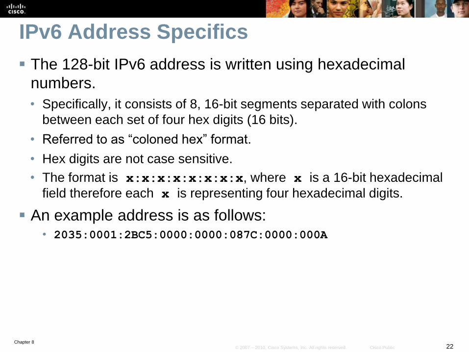
IPv6 Address Specifics
The 128-bit IPv6 address is written using hexadecimal
numbers.
• Specifically, it consists of 8, 16-bit segments separated with colons
between each set of four hex digits (16 bits).
• Referred to as “coloned hex” format.
• Hex digits are not case sensitive.
• The format is x:x:x:x:x:x:x:x, where x is a 16-bit hexadecimal
field therefore each x is representing four hexadecimal digits.
An example address is as follows:• 2035:0001:2BC5:0000:0000:087C:0000:000A
Chapter 823© 2007 – 2010, Cisco Systems, Inc. All rights reserved. Cisco Public
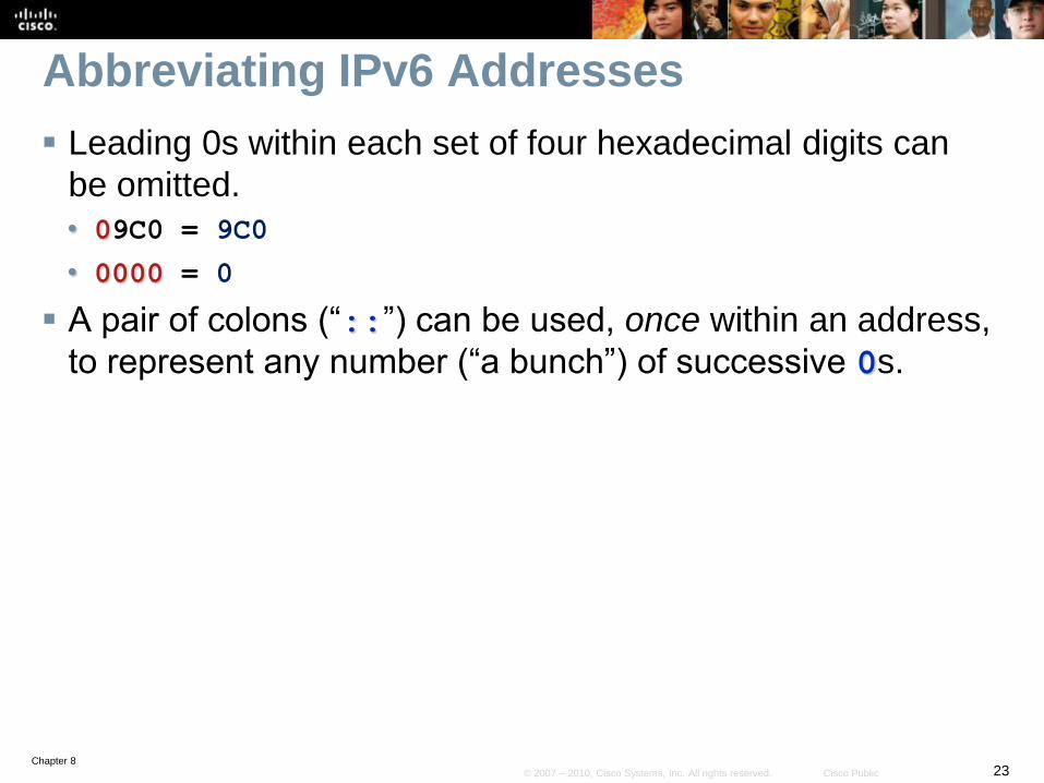
Abbreviating IPv6 Addresses
Leading 0s within each set of four hexadecimal digits can
be omitted.
• 09C0 = 9C0
• 0000 = 0
A pair of colons (“::”) can be used, once within an address,
to represent any number (“a bunch”) of successive 0s.
Chapter 824© 2007 – 2010, Cisco Systems, Inc. All rights reserved. Cisco Public
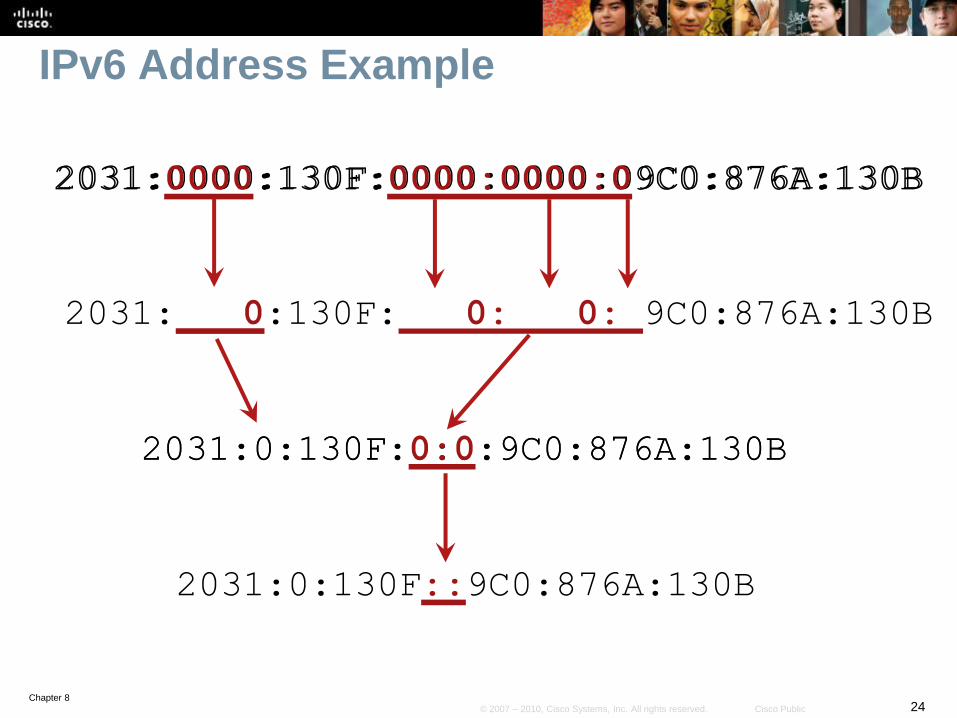
IPv6 Address Example
2031:0000:130F:0000:0000:09C0:876A:130B2031:0000:130F:0000:0000:09C0:876A:130B
2031: 0:130F: 0: 0: 9C0:876A:130B
2031:0:130F:0:0:9C0:876A:130B2031:0:130F:0:0:9C0:876A:130B
2031:0:130F::9C0:876A:130B
Chapter 825© 2007 – 2010, Cisco Systems, Inc. All rights reserved. Cisco Public
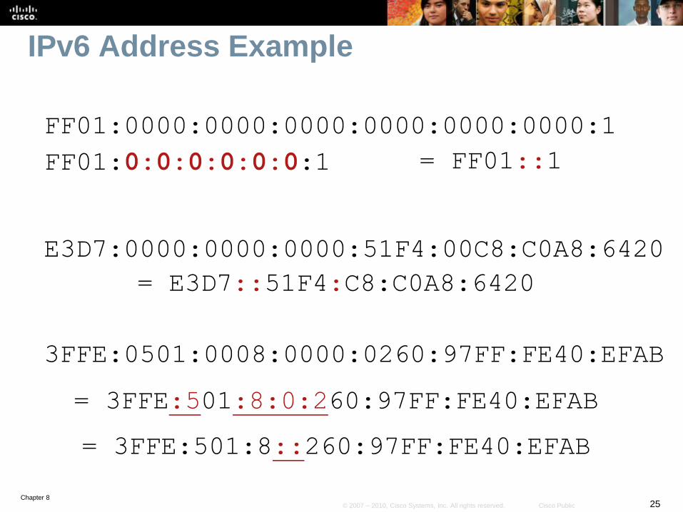
IPv6 Address Example
FF01:0:0:0:0:0:0:1 = FF01::1
E3D7:0000:0000:0000:51F4:00C8:C0A8:6420
= E3D7::51F4:C8:C0A8:6420
3FFE:0501:0008:0000:0260:97FF:FE40:EFAB
= 3FFE:501:8:0:260:97FF:FE40:EFAB
= 3FFE:501:8::260:97FF:FE40:EFAB
FF01:0000:0000:0000:0000:0000:0000:1
Chapter 826© 2007 – 2010, Cisco Systems, Inc. All rights reserved. Cisco Public
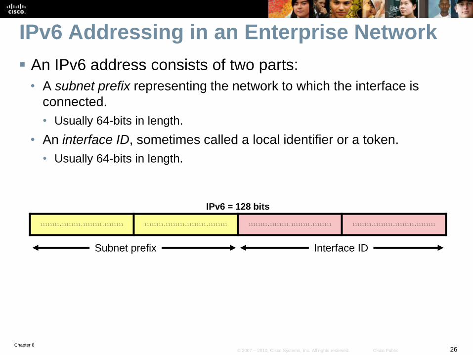
IPv6 Addressing in an Enterprise Network
An IPv6 address consists of two parts:
• A subnet prefix representing the network to which the interface is
connected.
• Usually 64-bits in length.
• An interface ID, sometimes called a local identifier or a token.
• Usually 64-bits in length.
IPv6 = 128 bits
11111111.11111111.11111111.11111111 11111111.11111111.11111111.11111111 11111111.11111111.11111111.11111111 11111111.11111111.11111111.11111111
Subnet prefix Interface ID
Chapter 827© 2007 – 2010, Cisco Systems, Inc. All rights reserved. Cisco Public
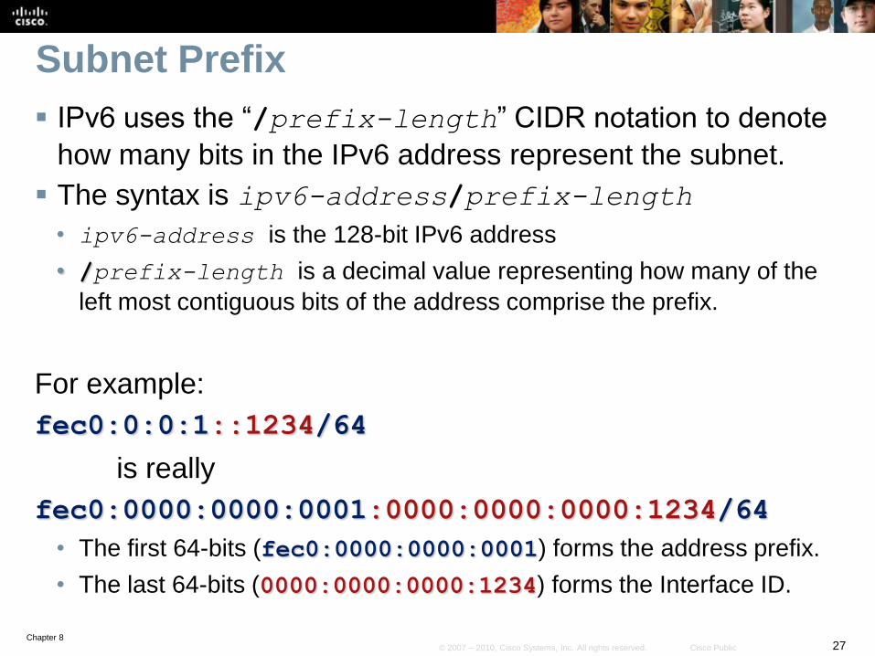
Subnet Prefix
IPv6 uses the “/prefix-length” CIDR notation to denote
how many bits in the IPv6 address represent the subnet.
The syntax is ipv6-address/prefix-length
• ipv6-address is the 128-bit IPv6 address
• /prefix-length is a decimal value representing how many of the
left most contiguous bits of the address comprise the prefix.
For example:
fec0:0:0:1::1234/64
is really
fec0:0000:0000:0001:0000:0000:0000:1234/64
• The first 64-bits (fec0:0000:0000:0001) forms the address prefix.
• The last 64-bits (0000:0000:0000:1234) forms the Interface ID.
Chapter 828© 2007 – 2010, Cisco Systems, Inc. All rights reserved. Cisco Public
Subnet Prefix
The prefix length is almost always /64.
• However, IPv6 rules allow for either shorter or longer prefixes
• Although prefixes shorter than /64 can be assigned to a device (e.g.,
/60), it is considered bad practice and has no real application.
Deploying a /64 IPv6 prefix on a device:
• Is pre-subscribed by RFC3177 (IAB/IESG Recommendations on IPv6
Address Allocations to Sites)
• Allows Stateless Address Auto Configuration (SLAAC) (RFC 2462)
Chapter 829© 2007 – 2010, Cisco Systems, Inc. All rights reserved. Cisco Public
Interface Identifiers
IPv6 addresses on a link must be unique.
• Although they all share the same 64-bit subnet prefix they are made
unique by the interface ID.
Because the prefix length is fixed and well-known (64-bits),
IPv6 hosts can automatically create a unique IPv6 address.
For example, the following Layer 2 protocols can
dynamically create the IPv6 address interface ID:
• Ethernet (using the EUI-64 format discussed later)
• PPP
• HDLC
• NBMA, Frame Relay
Chapter 830© 2007 – 2010, Cisco Systems, Inc. All rights reserved. Cisco Public
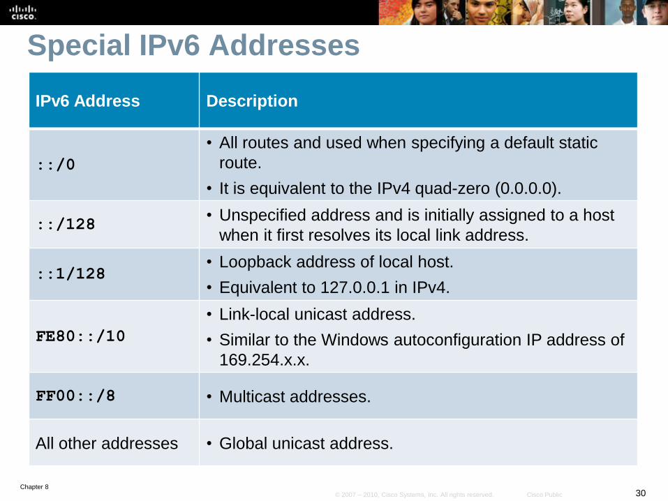
Special IPv6 Addresses
IPv6 Address Description
::/0
• All routes and used when specifying a default static
route.
• It is equivalent to the IPv4 quad-zero (0.0.0.0).
::/128• Unspecified address and is initially assigned to a host
when it first resolves its local link address.
::1/128• Loopback address of local host.
• Equivalent to 127.0.0.1 in IPv4.
FE80::/10
• Link-local unicast address.
• Similar to the Windows autoconfiguration IP address of
169.254.x.x.
FF00::/8 • Multicast addresses.
All other addresses • Global unicast address.
Chapter 831© 2007 – 2010, Cisco Systems, Inc. All rights reserved. Cisco Public
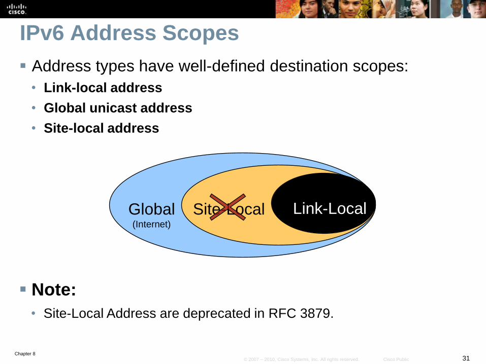
IPv6 Address Scopes
Address types have well-defined destination scopes:
• Link-local address
• Global unicast address
• Site-local address
Link-LocalSite-LocalGlobal(Internet)
Note:
• Site-Local Address are deprecated in RFC 3879.
Chapter 832© 2007 – 2010, Cisco Systems, Inc. All rights reserved. Cisco Public
Site-Local Addresses - Deprecated
Site-local addresses allowed devices in the same
organization, or site, to exchange data.
• Site-local addresses start with the prefix FEC0::/10.
They are analogous to IPv4's private address classes.
• However, using them would also mean that NAT would be required
and addresses would again not be end-to-end.
Site-local addresses are no longer supported (deprecated)
by RFC 3879.
Chapter 833© 2007 – 2010, Cisco Systems, Inc. All rights reserved. Cisco Public
Multiple IP Addresses per Interface
An interface can have multiple IPv6 addresses
simultaneously configured and enabled on it.
• However, it must have a link-local address.
Typically, an interface is assigned a link-local and one (or
more) global IPv6 address.
• For example, an Ethernet interface can have:
• Link-local address (e.g., FE80::21B:D5FF:FE5B:A408)
• Global unicast address (e.g., 2001:8:85A3:4289:21B:D5FF:FE5B:A408)
Note:
• An interface could also be configured to simultaneously support IPv4
and IPv6 addresses.
• This creates a “dual-stacked” interface which is discussed later.
Chapter 834© 2007 – 2010, Cisco Systems, Inc. All rights reserved. Cisco Public
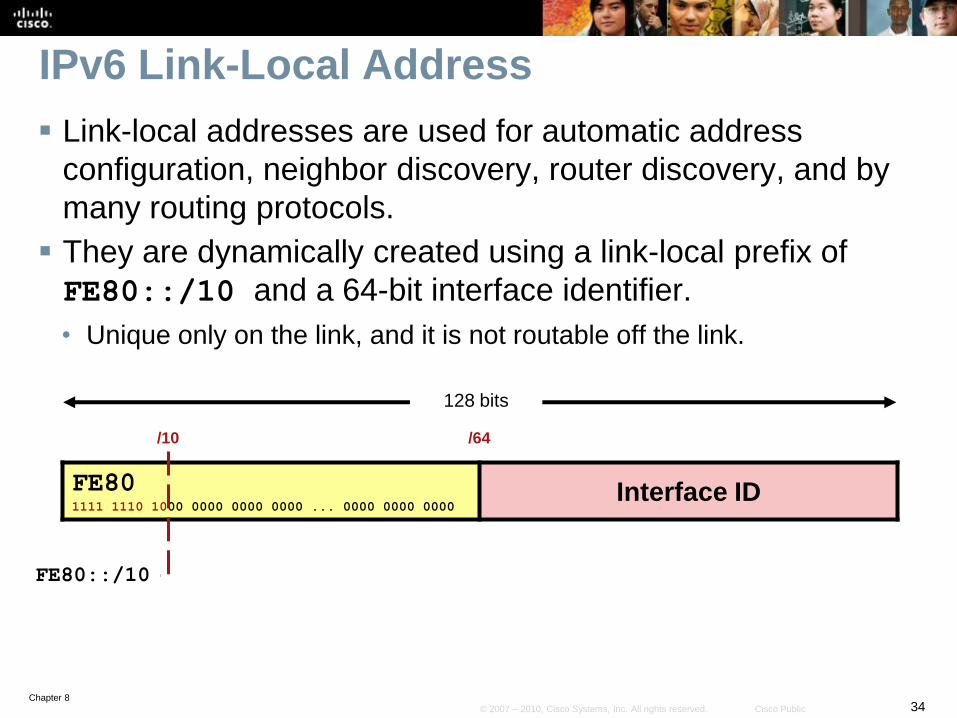
IPv6 Link-Local Address
Link-local addresses are used for automatic address
configuration, neighbor discovery, router discovery, and by
many routing protocols.
They are dynamically created using a link-local prefix of
FE80::/10 and a 64-bit interface identifier.
• Unique only on the link, and it is not routable off the link.
128 bits
FE801111 1110 1000 0000 0000 0000 ... 0000 0000 0000
Interface ID
/10
FE80::/10
/64
Chapter 835© 2007 – 2010, Cisco Systems, Inc. All rights reserved. Cisco Public
IPv6 Link-Local Address
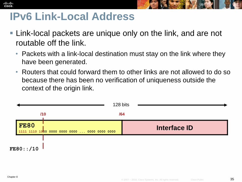
Link-local packets are unique only on the link, and are not
routable off the link.
• Packets with a link-local destination must stay on the link where they
have been generated.
• Routers that could forward them to other links are not allowed to do so
because there has been no verification of uniqueness outside the
context of the origin link.
128 bits
FE801111 1110 1000 0000 0000 0000 ... 0000 0000 0000
Interface ID
/10
FE80::/10
/64
Chapter 836© 2007 – 2010, Cisco Systems, Inc. All rights reserved. Cisco Public
IPv6 Link-Local Address
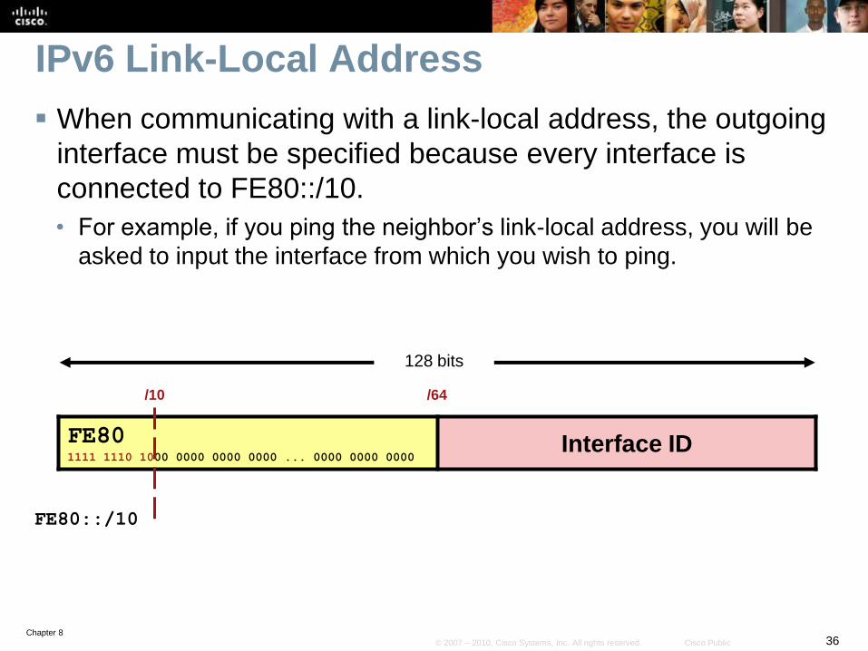
When communicating with a link-local address, the outgoing
interface must be specified because every interface is
connected to FE80::/10.
• For example, if you ping the neighbor’s link-local address, you will be
asked to input the interface from which you wish to ping.
128 bits
FE801111 1110 1000 0000 0000 0000 ... 0000 0000 0000
Interface ID
/10
FE80::/10
/64
Chapter 837© 2007 – 2010, Cisco Systems, Inc. All rights reserved. Cisco Public
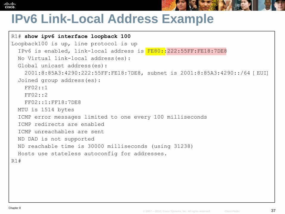
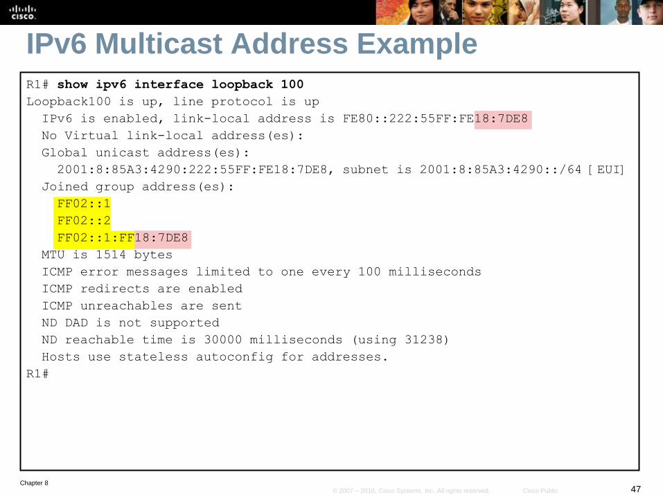
IPv6 Link-Local Address ExampleR1# show ipv6 interface loopback 100
Loopback100 is up, line protocol is up
IPv6 is enabled, link-local address is FE80::222:55FF:FE18:7DE8
No Virtual link-local address(es):
Global unicast address(es):
2001:8:85A3:4290:222:55FF:FE18:7DE8, subnet is 2001:8:85A3:4290::/64 [EUI]
Joined group address(es):
FF02::1
FF02::2
FF02::1:FF18:7DE8
MTU is 1514 bytes
ICMP error messages limited to one every 100 milliseconds
ICMP redirects are enabled
ICMP unreachables are sent
ND DAD is not supported
ND reachable time is 30000 milliseconds (using 31238)
Hosts use stateless autoconfig for addresses.
R1#
Chapter 838© 2007 – 2010, Cisco Systems, Inc. All rights reserved. Cisco Public
IPv6 Global Unicast Address
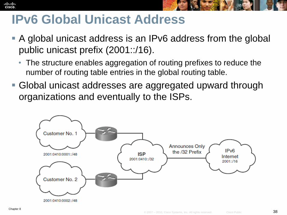
A global unicast address is an IPv6 address from the global
public unicast prefix (2001::/16).
• The structure enables aggregation of routing prefixes to reduce the
number of routing table entries in the global routing table.
Global unicast addresses are aggregated upward through
organizations and eventually to the ISPs.
Chapter 839© 2007 – 2010, Cisco Systems, Inc. All rights reserved. Cisco Public
IPv6 Global Unicast Address
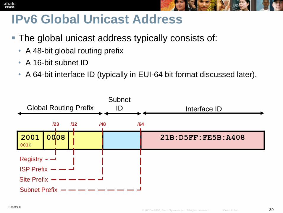
The global unicast address typically consists of:
• A 48-bit global routing prefix
• A 16-bit subnet ID
• A 64-bit interface ID (typically in EUI-64 bit format discussed later).
Global Routing PrefixSubnet
ID Interface ID
20010010
0008 21B:D5FF:FE5B:A408
/23
Registry
/32
ISP Prefix
/48
Site Prefix
/64
Subnet Prefix
Chapter 840© 2007 – 2010, Cisco Systems, Inc. All rights reserved. Cisco Public
IPv6 Global Unicast Address
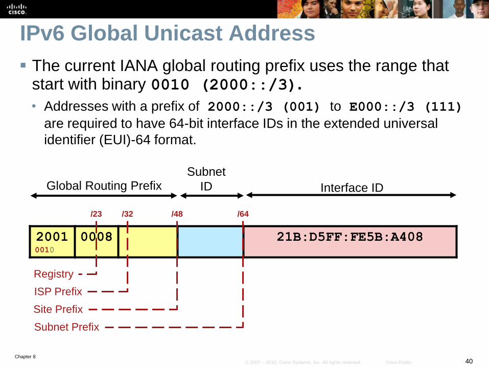
The current IANA global routing prefix uses the range that start with binary 0010 (2000::/3).
• Addresses with a prefix of 2000::/3 (001) to E000::/3 (111)
are required to have 64-bit interface IDs in the extended universal
identifier (EUI)-64 format.
Global Routing PrefixSubnet
ID Interface ID
20010010
0008 21B:D5FF:FE5B:A408
/23
Registry
/32
ISP Prefix
/48
Site Prefix
/64
Subnet Prefix
Chapter 841© 2007 – 2010, Cisco Systems, Inc. All rights reserved. Cisco Public
IPv6 Global Unicast Address
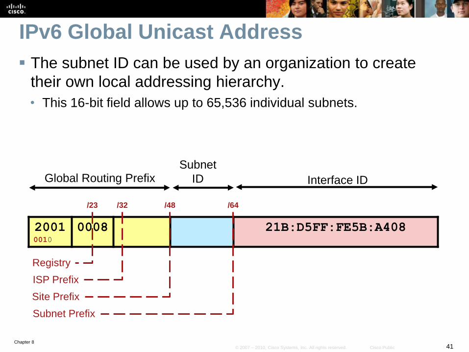
The subnet ID can be used by an organization to create
their own local addressing hierarchy.
• This 16-bit field allows up to 65,536 individual subnets.
Global Routing PrefixSubnet
ID Interface ID
20010010
0008 21B:D5FF:FE5B:A408
/23
Registry
/32
ISP Prefix
/48
Site Prefix
/64
Subnet Prefix
Chapter 842© 2007 – 2010, Cisco Systems, Inc. All rights reserved. Cisco Public
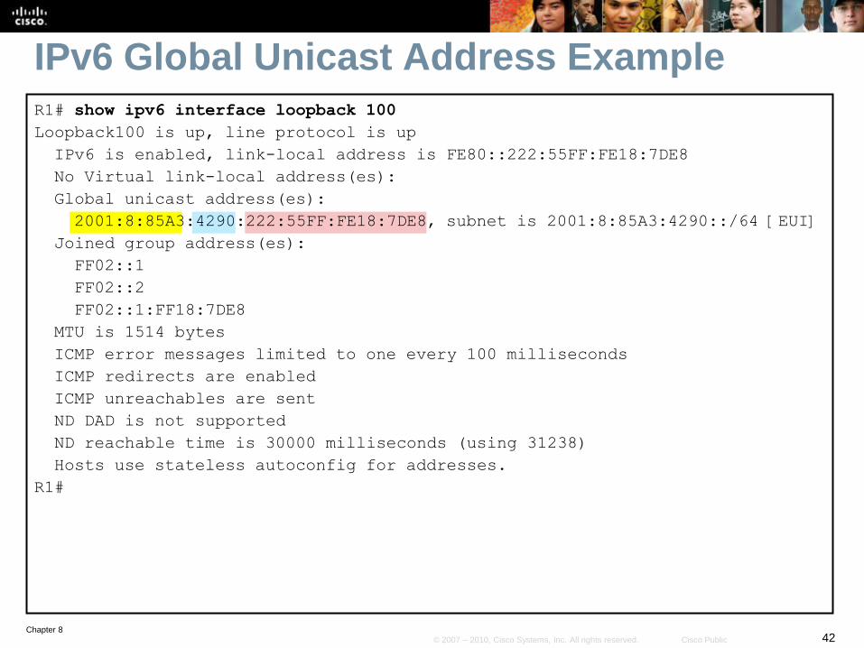
IPv6 Global Unicast Address ExampleR1# show ipv6 interface loopback 100
Loopback100 is up, line protocol is up
IPv6 is enabled, link-local address is FE80::222:55FF:FE18:7DE8
No Virtual link-local address(es):
Global unicast address(es):
2001:8:85A3:4290:222:55FF:FE18:7DE8, subnet is 2001:8:85A3:4290::/64 [EUI]
Joined group address(es):
FF02::1
FF02::2
FF02::1:FF18:7DE8
MTU is 1514 bytes
ICMP error messages limited to one every 100 milliseconds
ICMP redirects are enabled
ICMP unreachables are sent
ND DAD is not supported
ND reachable time is 30000 milliseconds (using 31238)
Hosts use stateless autoconfig for addresses.
R1#
Chapter 843© 2007 – 2010, Cisco Systems, Inc. All rights reserved. Cisco Public
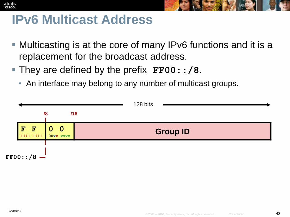
IPv6 Multicast Address
Multicasting is at the core of many IPv6 functions and it is a
replacement for the broadcast address.
They are defined by the prefix FF00::/8.
• An interface may belong to any number of multicast groups.
/16/8
FF00::/8
128 bits
F F1111 1111
0 000xx xxxx
Group ID
Chapter 844© 2007 – 2010, Cisco Systems, Inc. All rights reserved. Cisco Public
F F1111 1111
0 000xx xxxx
Group ID
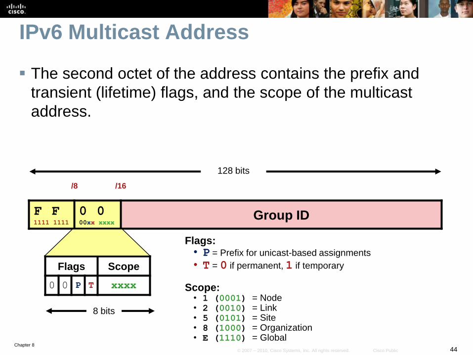
IPv6 Multicast Address
The second octet of the address contains the prefix and
transient (lifetime) flags, and the scope of the multicast
address.
Flags Scope
0 0 P T xxxx
8 bits
Flags:• P = Prefix for unicast-based assignments
• T = 0 if permanent, 1 if temporary
Scope:• 1 (0001) = Node• 2 (0010) = Link• 5 (0101) = Site• 8 (1000) = Organization• E (1110) = Global
/16/8
128 bits
Chapter 845© 2007 – 2010, Cisco Systems, Inc. All rights reserved. Cisco Public
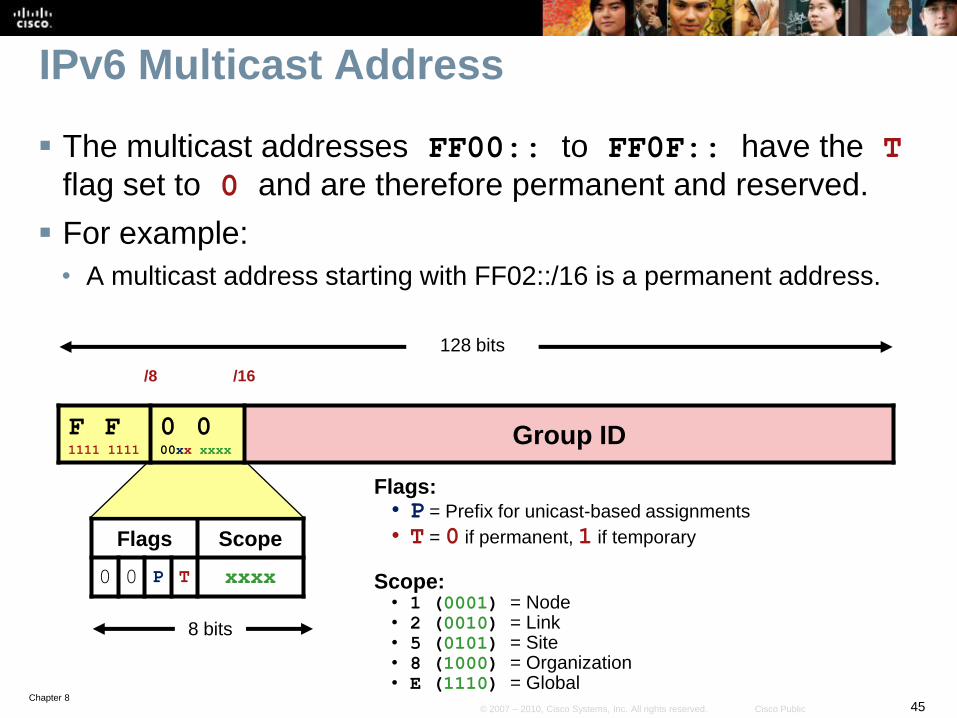
IPv6 Multicast Address
The multicast addresses FF00:: to FF0F:: have the T
flag set to 0 and are therefore permanent and reserved.
For example:
• A multicast address starting with FF02::/16 is a permanent address.
Flags Scope
0 0 P T xxxx
8 bits
Flags:• P = Prefix for unicast-based assignments
• T = 0 if permanent, 1 if temporary
Scope:• 1 (0001) = Node• 2 (0010) = Link• 5 (0101) = Site• 8 (1000) = Organization• E (1110) = Global
/16/8
128 bits
F F1111 1111
0 000xx xxxx
Group ID
Chapter 846© 2007 – 2010, Cisco Systems, Inc. All rights reserved. Cisco Public
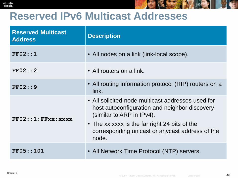
Reserved IPv6 Multicast Addresses
Reserved Multicast
AddressDescription
FF02::1 • All nodes on a link (link-local scope).
FF02::2 • All routers on a link.
FF02::9• All routing information protocol (RIP) routers on a
link.
FF02::1:FFxx:xxxx
• All solicited-node multicast addresses used for
host autoconfiguration and neighbor discovery
(similar to ARP in IPv4).
• The xx:xxxx is the far right 24 bits of the
corresponding unicast or anycast address of the
node.
FF05::101 • All Network Time Protocol (NTP) servers.
Chapter 847© 2007 – 2010, Cisco Systems, Inc. All rights reserved. Cisco Public
IPv6 Multicast Address ExampleR1# show ipv6 interface loopback 100
Loopback100 is up, line protocol is up
IPv6 is enabled, link-local address is FE80::222:55FF:FE18:7DE8
No Virtual link-local address(es):
Global unicast address(es):
2001:8:85A3:4290:222:55FF:FE18:7DE8, subnet is 2001:8:85A3:4290::/64 [EUI]
Joined group address(es):
FF02::1
FF02::2
FF02::1:FF18:7DE8
MTU is 1514 bytes
ICMP error messages limited to one every 100 milliseconds
ICMP redirects are enabled
ICMP unreachables are sent
ND DAD is not supported
ND reachable time is 30000 milliseconds (using 31238)
Hosts use stateless autoconfig for addresses.
R1#
Chapter 848© 2007 – 2010, Cisco Systems, Inc. All rights reserved. Cisco Public
Solicited-Node Multicast Addresses
The solicited-node multicast address (FF02::1:FF) is used
for:
• Neighbor discovery (ND) process
• Stateless address autoconfiguration
The Neighbor discovery (ND) process is used to:
• Determine the local-link address of the neighbor.
• Determine the routers on the link and default route.
• Actively keep track of neighbor reachability.
• Send network information from routers to hosts
Chapter 849© 2007 – 2010, Cisco Systems, Inc. All rights reserved. Cisco Public
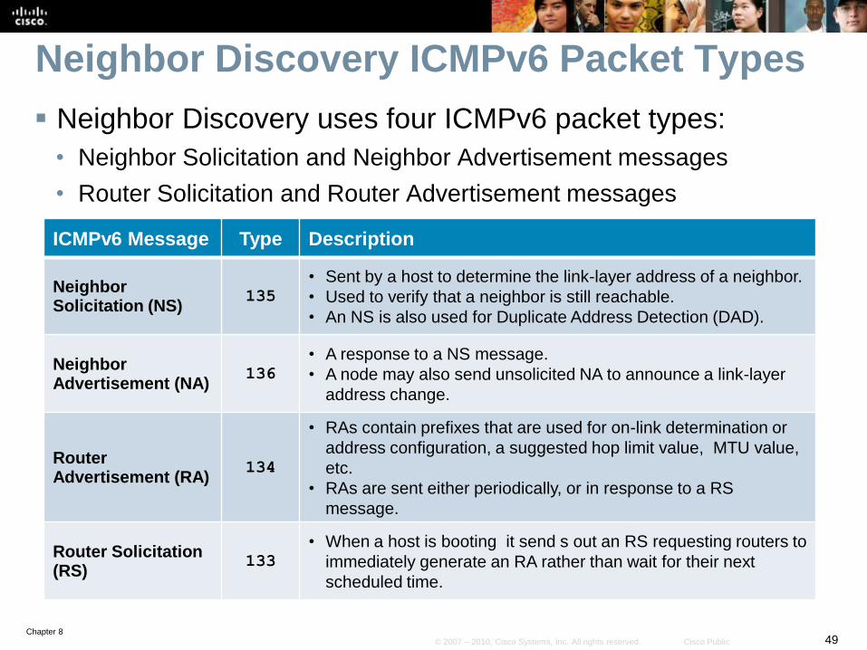
Neighbor Discovery ICMPv6 Packet Types
Neighbor Discovery uses four ICMPv6 packet types:
• Neighbor Solicitation and Neighbor Advertisement messages
• Router Solicitation and Router Advertisement messages
ICMPv6 Message Type Description
Neighbor Solicitation (NS)
135
• Sent by a host to determine the link-layer address of a neighbor.
• Used to verify that a neighbor is still reachable.
• An NS is also used for Duplicate Address Detection (DAD).
Neighbor Advertisement (NA)
136
• A response to a NS message.
• A node may also send unsolicited NA to announce a link-layer
address change.
Router Advertisement (RA)
134
• RAs contain prefixes that are used for on-link determination or
address configuration, a suggested hop limit value, MTU value,
etc.
• RAs are sent either periodically, or in response to a RS
message.
Router Solicitation (RS)
133
• When a host is booting it send s out an RS requesting routers to
immediately generate an RA rather than wait for their next
scheduled time.
Chapter 850© 2007 – 2010, Cisco Systems, Inc. All rights reserved. Cisco Public
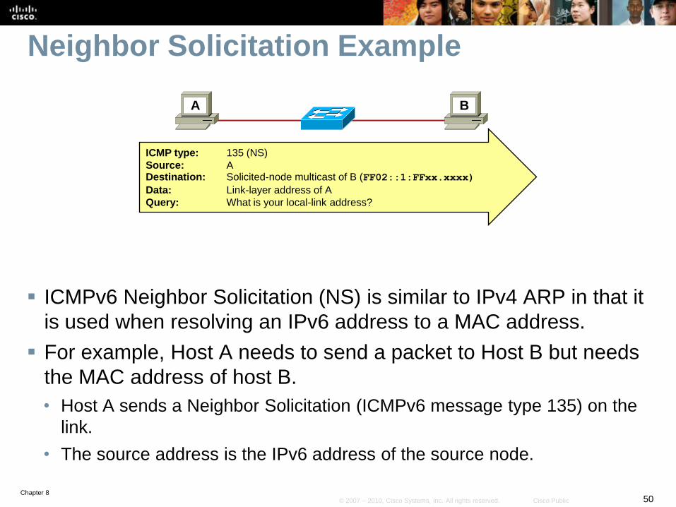
Neighbor Solicitation Example
ICMPv6 Neighbor Solicitation (NS) is similar to IPv4 ARP in that it
is used when resolving an IPv6 address to a MAC address.
For example, Host A needs to send a packet to Host B but needs
the MAC address of host B.
• Host A sends a Neighbor Solicitation (ICMPv6 message type 135) on the
link.
• The source address is the IPv6 address of the source node.
A B
ICMP type: 135 (NS)
Source: ADestination: Solicited-node multicast of B (FF02::1:FFxx.xxxx)
Data: Link-layer address of A
Query: What is your local-link address?
Chapter 851© 2007 – 2010, Cisco Systems, Inc. All rights reserved. Cisco Public
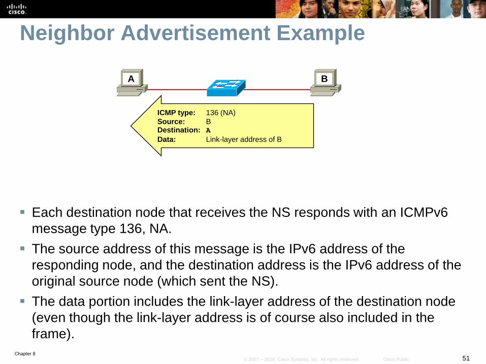
Neighbor Advertisement Example
Each destination node that receives the NS responds with an ICMPv6
message type 136, NA.
The source address of this message is the IPv6 address of the
responding node, and the destination address is the IPv6 address of the
original source node (which sent the NS).
The data portion includes the link-layer address of the destination node
(even though the link-layer address is of course also included in the
frame).
A B
ICMP type: 136 (NA)
Source: BDestination: A
Data: Link-layer address of B
Chapter 852© 2007 – 2010, Cisco Systems, Inc. All rights reserved. Cisco Public
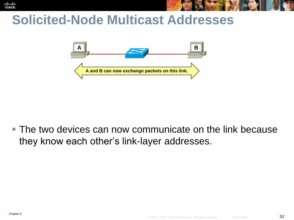
Solicited-Node Multicast Addresses
The two devices can now communicate on the link because
they know each other’s link-layer addresses.
A B
A and B can now exchange packets on this link.
Chapter 853© 2007 – 2010, Cisco Systems, Inc. All rights reserved. Cisco Public
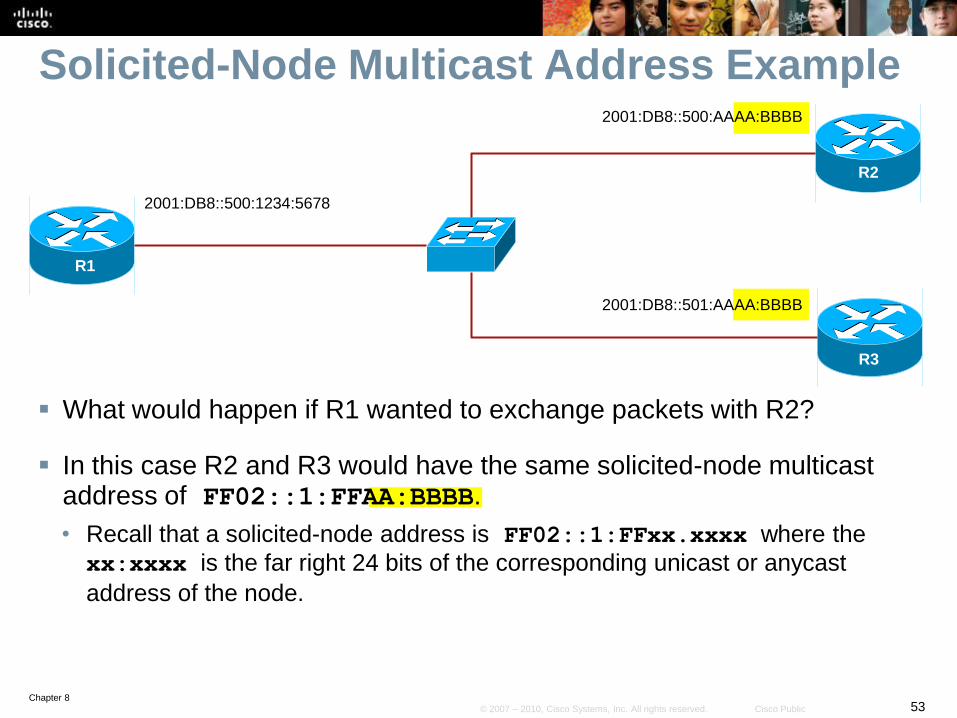
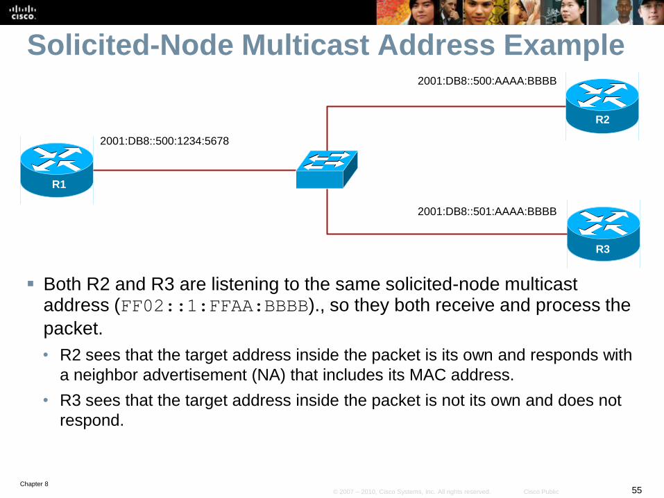
Solicited-Node Multicast Address Example
What would happen if R1 wanted to exchange packets with R2?
In this case R2 and R3 would have the same solicited-node multicast address of FF02::1:FFAA:BBBB.
• Recall that a solicited-node address is FF02::1:FFxx.xxxx where the
xx:xxxx is the far right 24 bits of the corresponding unicast or anycast
address of the node.
R2
R1
R3
2001:DB8::500:1234:5678
2001:DB8::500:AAAA:BBBB
2001:DB8::501:AAAA:BBBB
Chapter 854© 2007 – 2010, Cisco Systems, Inc. All rights reserved. Cisco Public
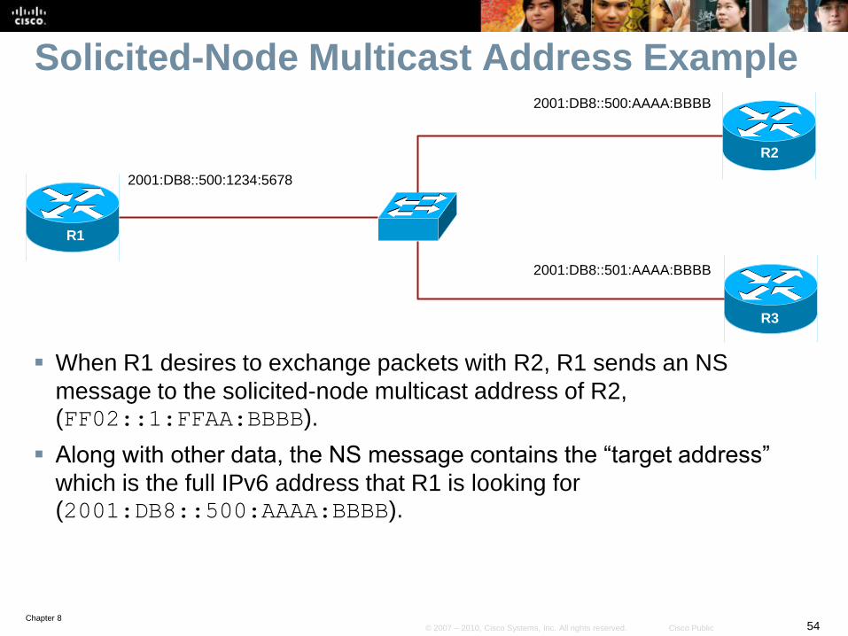
Solicited-Node Multicast Address Example
When R1 desires to exchange packets with R2, R1 sends an NS
message to the solicited-node multicast address of R2, (FF02::1:FFAA:BBBB).
Along with other data, the NS message contains the “target address”
which is the full IPv6 address that R1 is looking for (2001:DB8::500:AAAA:BBBB).
R2
R1
R3
2001:DB8::500:1234:5678
2001:DB8::500:AAAA:BBBB
2001:DB8::501:AAAA:BBBB
Chapter 855© 2007 – 2010, Cisco Systems, Inc. All rights reserved. Cisco Public
Solicited-Node Multicast Address Example
Both R2 and R3 are listening to the same solicited-node multicast address (FF02::1:FFAA:BBBB)., so they both receive and process the
packet.
• R2 sees that the target address inside the packet is its own and responds with
a neighbor advertisement (NA) that includes its MAC address.
• R3 sees that the target address inside the packet is not its own and does not
respond.
R2
R1
R3
2001:DB8::500:1234:5678
2001:DB8::500:AAAA:BBBB
2001:DB8::501:AAAA:BBBB
Chapter 856© 2007 – 2010, Cisco Systems, Inc. All rights reserved. Cisco Public
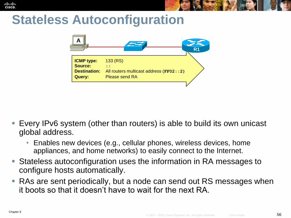
Stateless Autoconfiguration
Every IPv6 system (other than routers) is able to build its own unicast global address.
• Enables new devices (e.g., cellular phones, wireless devices, home appliances, and home networks) to easily connect to the Internet.
Stateless autoconfiguration uses the information in RA messages to configure hosts automatically.
RAs are sent periodically, but a node can send out RS messages when it boots so that it doesn’t have to wait for the next RA.
A
ICMP type: 133 (RS)Source: ::
Destination: All routers multicast address (FF02::2)
Query: Please send RA
R1
Chapter 857© 2007 – 2010, Cisco Systems, Inc. All rights reserved. Cisco Public
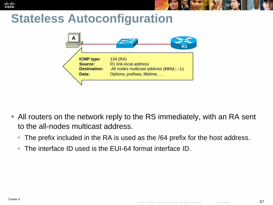
Stateless Autoconfiguration
All routers on the network reply to the RS immediately, with an RA sent
to the all-nodes multicast address.
• The prefix included in the RA is used as the /64 prefix for the host address.
• The interface ID used is the EUI-64 format interface ID.
A
R1
ICMP type: 134 (RA)
Source: R1 link-local addressDestination: All nodes multicast address (FF02::1)
Data: Options, prefixes, lifetime, …
Chapter 858© 2007 – 2010, Cisco Systems, Inc. All rights reserved. Cisco Public
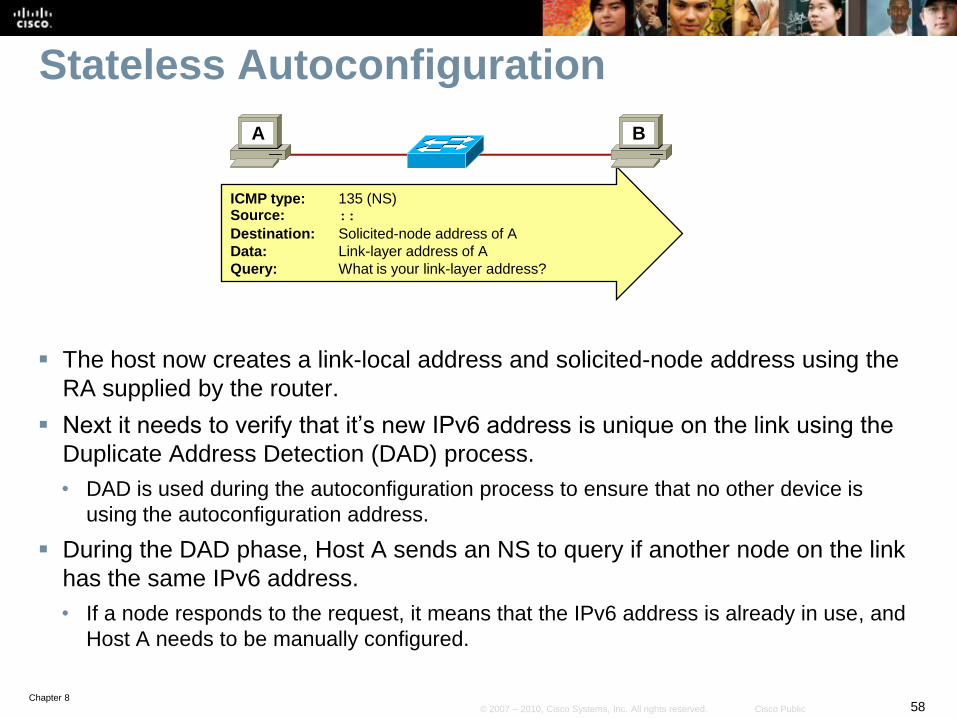
Stateless Autoconfiguration
The host now creates a link-local address and solicited-node address using the
RA supplied by the router.
Next it needs to verify that it’s new IPv6 address is unique on the link using the
Duplicate Address Detection (DAD) process.
• DAD is used during the autoconfiguration process to ensure that no other device is
using the autoconfiguration address.
During the DAD phase, Host A sends an NS to query if another node on the link
has the same IPv6 address.
• If a node responds to the request, it means that the IPv6 address is already in use, and
Host A needs to be manually configured.
ICMP type: 135 (NS)Source: ::
Destination: Solicited-node address of A
Data: Link-layer address of A
Query: What is your link-layer address?
A B
Chapter 859© 2007 – 2010, Cisco Systems, Inc. All rights reserved. Cisco Public
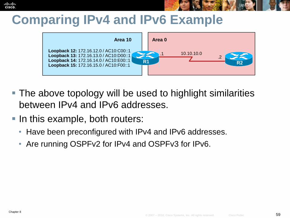
Comparing IPv4 and IPv6 Example
The above topology will be used to highlight similarities
between IPv4 and IPv6 addresses.
In this example, both routers:
• Have been preconfigured with IPv4 and IPv6 addresses.
• Are running OSPFv2 for IPv4 and OSPFv3 for IPv6.
R2
10.10.10.0.1
R1
Area 10
.2
Loopback 12: 172.16.12.0 / AC10:C00::1Loopback 13: 172.16.13.0 / AC10:D00::1Loopback 14: 172.16.14.0 / AC10:E00::1Loopback 15: 172.16.15.0 / AC10:F00::1
Area 0
Chapter 860© 2007 – 2010, Cisco Systems, Inc. All rights reserved. Cisco Public
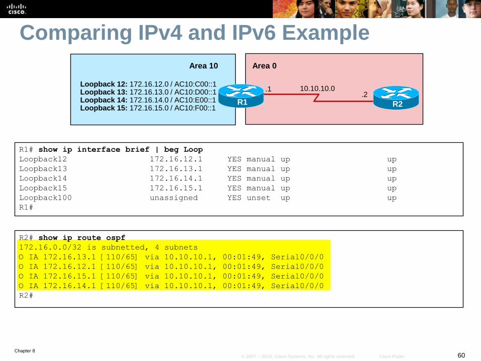
Comparing IPv4 and IPv6 Example
R2# show ip route ospf
172.16.0.0/32 is subnetted, 4 subnets
O IA 172.16.13.1 [110/65] via 10.10.10.1, 00:01:49, Serial0/0/0
O IA 172.16.12.1 [110/65] via 10.10.10.1, 00:01:49, Serial0/0/0
O IA 172.16.15.1 [110/65] via 10.10.10.1, 00:01:49, Serial0/0/0
O IA 172.16.14.1 [110/65] via 10.10.10.1, 00:01:49, Serial0/0/0
R2#
R1# show ip interface brief | beg Loop
Loopback12 172.16.12.1 YES manual up up
Loopback13 172.16.13.1 YES manual up up
Loopback14 172.16.14.1 YES manual up up
Loopback15 172.16.15.1 YES manual up up
Loopback100 unassigned YES unset up up
R1#
R2
10.10.10.0.1
R1
Area 10
.2
Loopback 12: 172.16.12.0 / AC10:C00::1Loopback 13: 172.16.13.0 / AC10:D00::1Loopback 14: 172.16.14.0 / AC10:E00::1Loopback 15: 172.16.15.0 / AC10:F00::1
Area 0
Chapter 861© 2007 – 2010, Cisco Systems, Inc. All rights reserved. Cisco Public
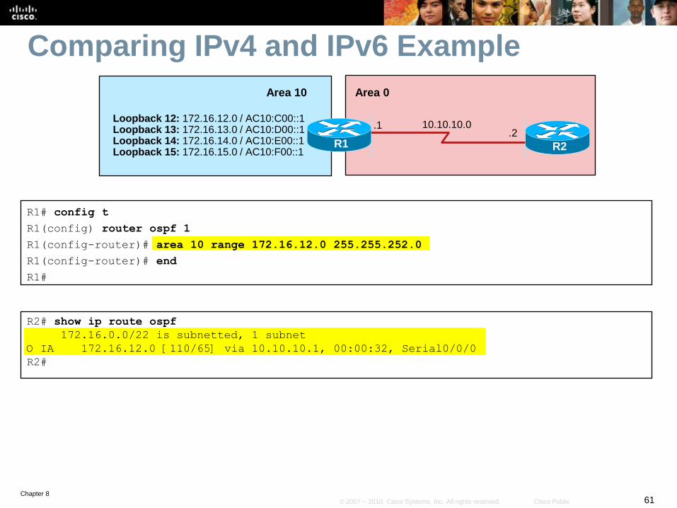
Comparing IPv4 and IPv6 Example
R1# config t
R1(config) router ospf 1
R1(config-router)# area 10 range 172.16.12.0 255.255.252.0
R1(config-router)# end
R1#
R2# show ip route ospf
172.16.0.0/22 is subnetted, 1 subnet
O IA 172.16.12.0 [110/65] via 10.10.10.1, 00:00:32, Serial0/0/0
R2#
R2
10.10.10.0.1
R1
Area 10
.2
Loopback 12: 172.16.12.0 / AC10:C00::1Loopback 13: 172.16.13.0 / AC10:D00::1Loopback 14: 172.16.14.0 / AC10:E00::1Loopback 15: 172.16.15.0 / AC10:F00::1
Area 0
Chapter 862© 2007 – 2010, Cisco Systems, Inc. All rights reserved. Cisco Public
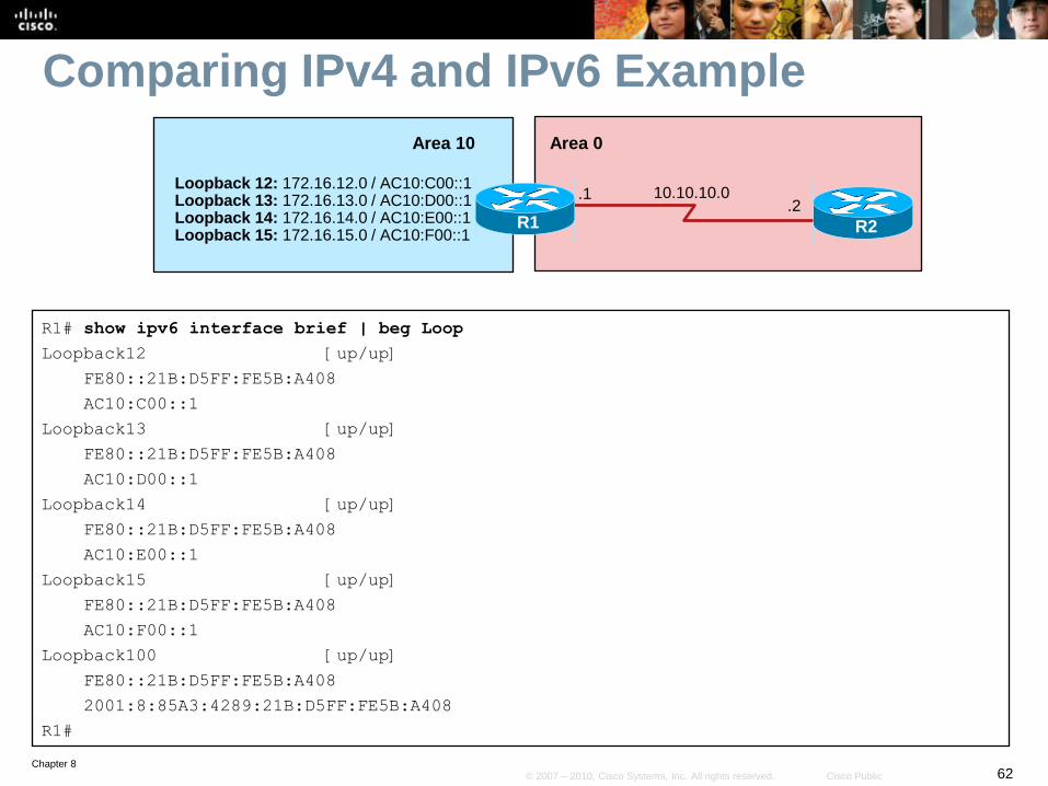
Comparing IPv4 and IPv6 Example
R1# show ipv6 interface brief | beg Loop
Loopback12 [up/up]
FE80::21B:D5FF:FE5B:A408
AC10:C00::1
Loopback13 [up/up]
FE80::21B:D5FF:FE5B:A408
AC10:D00::1
Loopback14 [up/up]
FE80::21B:D5FF:FE5B:A408
AC10:E00::1
Loopback15 [up/up]
FE80::21B:D5FF:FE5B:A408
AC10:F00::1
Loopback100 [up/up]
FE80::21B:D5FF:FE5B:A408
2001:8:85A3:4289:21B:D5FF:FE5B:A408
R1#
R2
10.10.10.0.1
R1
Area 10
.2
Loopback 12: 172.16.12.0 / AC10:C00::1Loopback 13: 172.16.13.0 / AC10:D00::1Loopback 14: 172.16.14.0 / AC10:E00::1Loopback 15: 172.16.15.0 / AC10:F00::1
Area 0
Chapter 863© 2007 – 2010, Cisco Systems, Inc. All rights reserved. Cisco Public
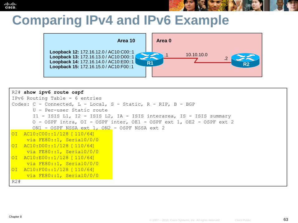
Comparing IPv4 and IPv6 Example
R2# show ipv6 route ospf
IPv6 Routing Table - 6 entries
Codes: C - Connected, L - Local, S - Static, R - RIP, B - BGP
U - Per-user Static route
I1 - ISIS L1, I2 - ISIS L2, IA - ISIS interarea, IS - ISIS summary
O - OSPF intra, OI - OSPF inter, OE1 - OSPF ext 1, OE2 - OSPF ext 2
ON1 - OSPF NSSA ext 1, ON2 - OSPF NSSA ext 2
OI AC10:C00::1/128 [110/64]
via FE80::1, Serial0/0/0
OI AC10:D00::1/128 [110/64]
via FE80::1, Serial0/0/0
OI AC10:E00::1/128 [110/64]
via FE80::1, Serial0/0/0
OI AC10:F00::1/128 [110/64]
via FE80::1, Serial0/0/0
R2#
R2
10.10.10.0.1
R1
Area 10
.2
Loopback 12: 172.16.12.0 / AC10:C00::1Loopback 13: 172.16.13.0 / AC10:D00::1Loopback 14: 172.16.14.0 / AC10:E00::1Loopback 15: 172.16.15.0 / AC10:F00::1
Area 0
Chapter 864© 2007 – 2010, Cisco Systems, Inc. All rights reserved. Cisco Public
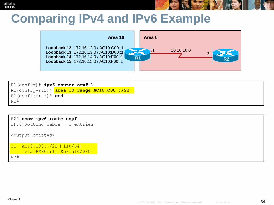
Comparing IPv4 and IPv6 Example
R1(config)# ipv6 router ospf 1
R1(config-rtr)# area 10 range AC10:C00::/22
R1(config-rtr)# end
R1#
R2# show ipv6 route ospf
IPv6 Routing Table - 3 entries
<output omitted>
OI AC10:C00::/22 [110/64]
via FE80::1, Serial0/0/0
R2#
R2
10.10.10.0.1
R1
Area 10
.2
Loopback 12: 172.16.12.0 / AC10:C00::1Loopback 13: 172.16.13.0 / AC10:D00::1Loopback 14: 172.16.14.0 / AC10:E00::1Loopback 15: 172.16.15.0 / AC10:F00::1
Area 0
Chapter 865© 2007 – 2010, Cisco Systems, Inc. All rights reserved. Cisco Public
Configuring and Verifying IPv6 Unicast Addresses
Chapter 866© 2007 – 2010, Cisco Systems, Inc. All rights reserved. Cisco Public
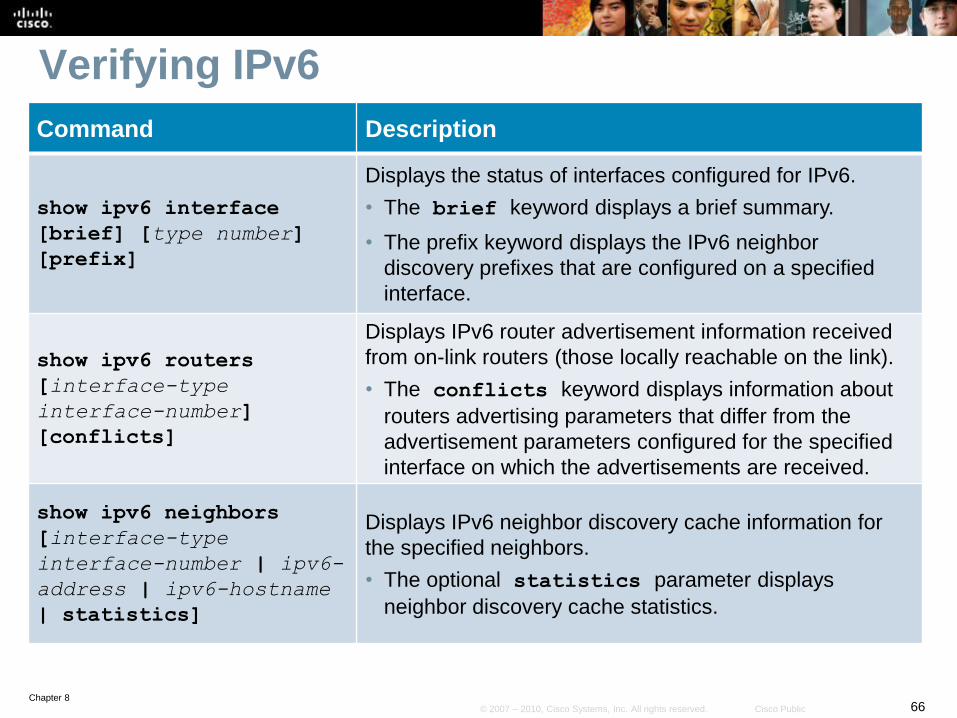
Verifying IPv6
Command Description
show ipv6 interface
[brief] [type number]
[prefix]
Displays the status of interfaces configured for IPv6.
• The brief keyword displays a brief summary.
• The prefix keyword displays the IPv6 neighbor
discovery prefixes that are configured on a specified
interface.
show ipv6 routers
[interface-type
interface-number]
[conflicts]
Displays IPv6 router advertisement information received
from on-link routers (those locally reachable on the link).
• The conflicts keyword displays information about
routers advertising parameters that differ from the
advertisement parameters configured for the specified
interface on which the advertisements are received.
show ipv6 neighbors
[interface-type
interface-number | ipv6-
address | ipv6-hostname
| statistics]
Displays IPv6 neighbor discovery cache information for
the specified neighbors.
• The optional statistics parameter displays
neighbor discovery cache statistics.
Chapter 867© 2007 – 2010, Cisco Systems, Inc. All rights reserved. Cisco Public
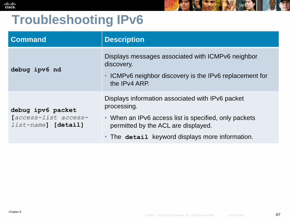
Troubleshooting IPv6
Command Description
debug ipv6 nd
Displays messages associated with ICMPv6 neighbor
discovery.
• ICMPv6 neighbor discovery is the IPv6 replacement for
the IPv4 ARP.
debug ipv6 packet
[access-list access-
list-name] [detail]
Displays information associated with IPv6 packet
processing.
• When an IPv6 access list is specified, only packets
permitted by the ACL are displayed.
• The detail keyword displays more information.
Chapter 868© 2007 – 2010, Cisco Systems, Inc. All rights reserved. Cisco Public
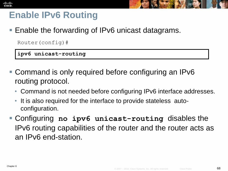
Enable IPv6 Routing
Enable the forwarding of IPv6 unicast datagrams.
Router(config)#
ipv6 unicast-routing
Command is only required before configuring an IPv6
routing protocol.
• Command is not needed before configuring IPv6 interface addresses.
• It is also required for the interface to provide stateless auto-
configuration.
Configuring no ipv6 unicast-routing disables the
IPv6 routing capabilities of the router and the router acts as
an IPv6 end-station.
Chapter 869© 2007 – 2010, Cisco Systems, Inc. All rights reserved. Cisco Public
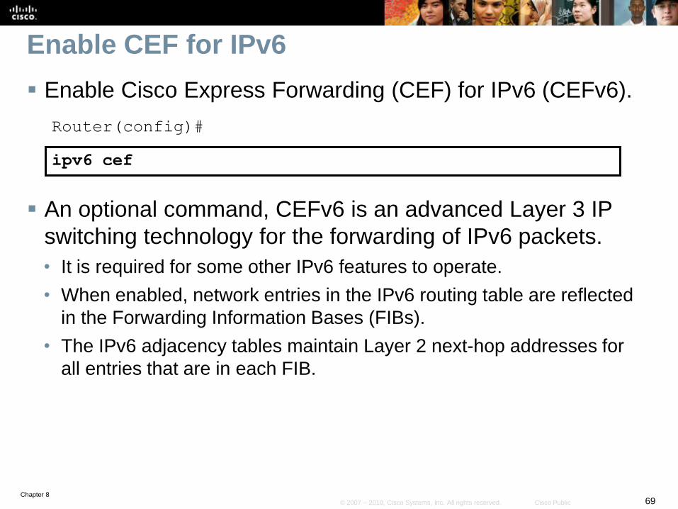
Enable CEF for IPv6
Enable Cisco Express Forwarding (CEF) for IPv6 (CEFv6).
Router(config)#
ipv6 cef
An optional command, CEFv6 is an advanced Layer 3 IP
switching technology for the forwarding of IPv6 packets.
• It is required for some other IPv6 features to operate.
• When enabled, network entries in the IPv6 routing table are reflected
in the Forwarding Information Bases (FIBs).
• The IPv6 adjacency tables maintain Layer 2 next-hop addresses for
all entries that are in each FIB.
Chapter 870© 2007 – 2010, Cisco Systems, Inc. All rights reserved. Cisco Public
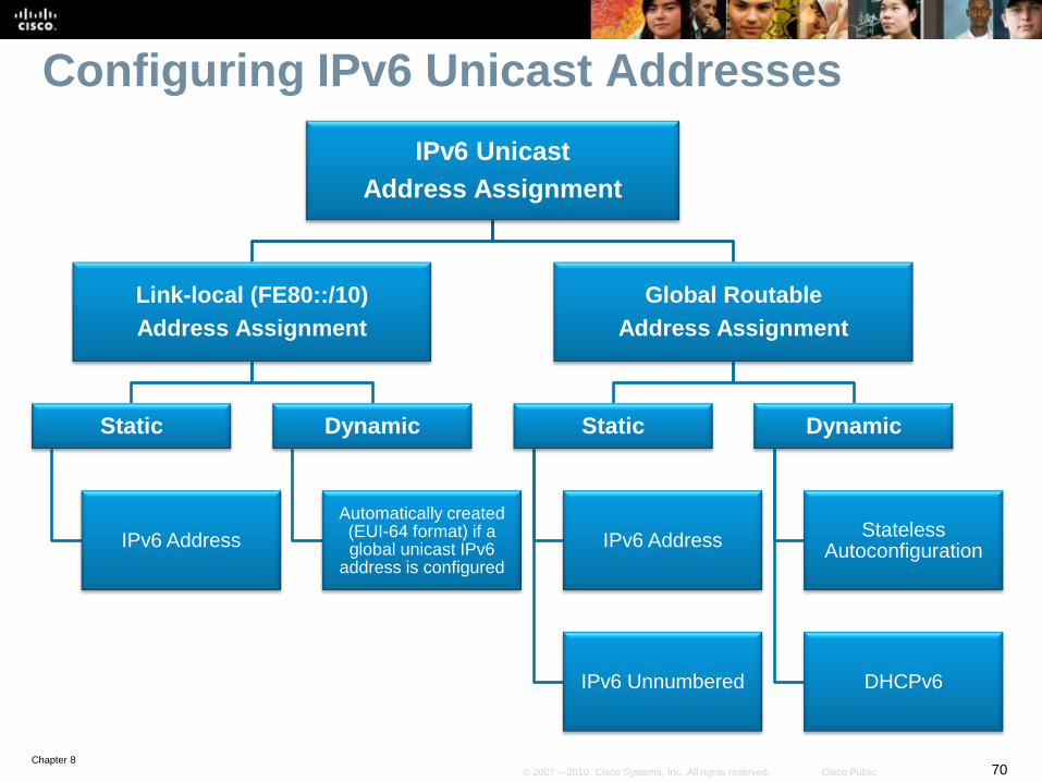
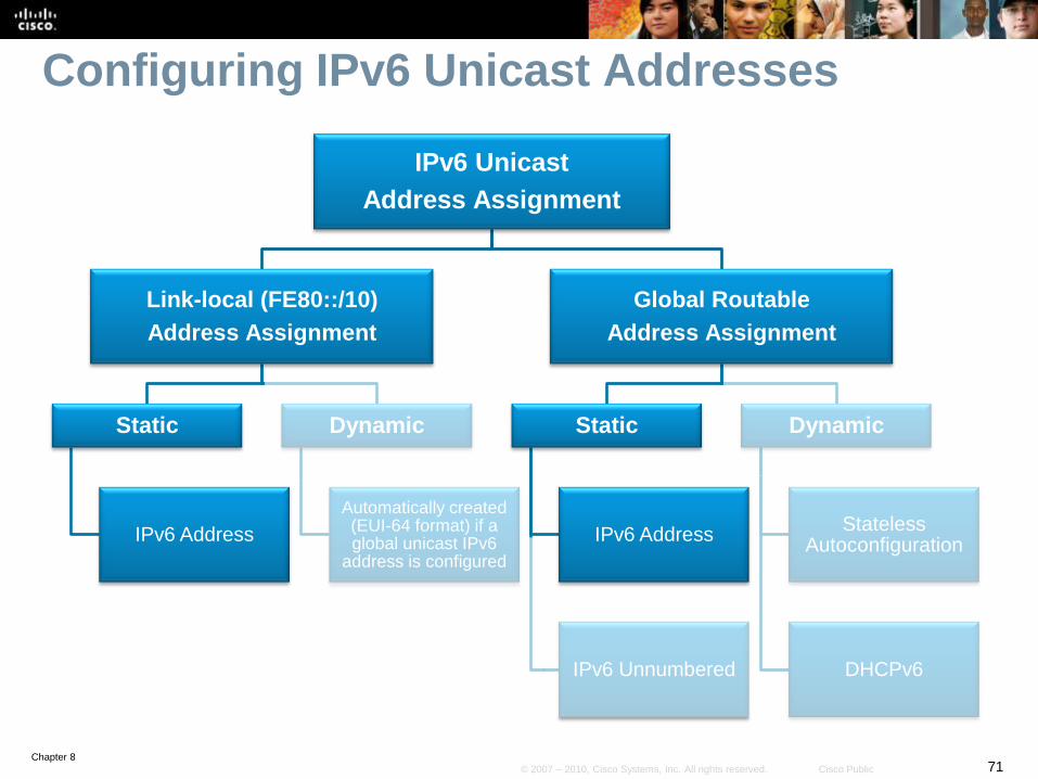
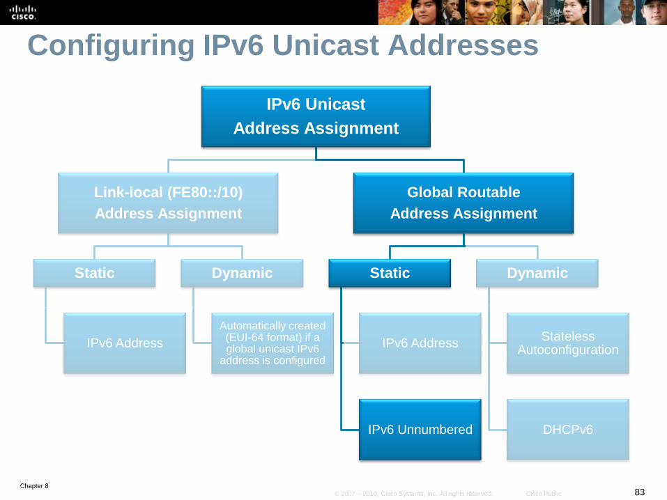
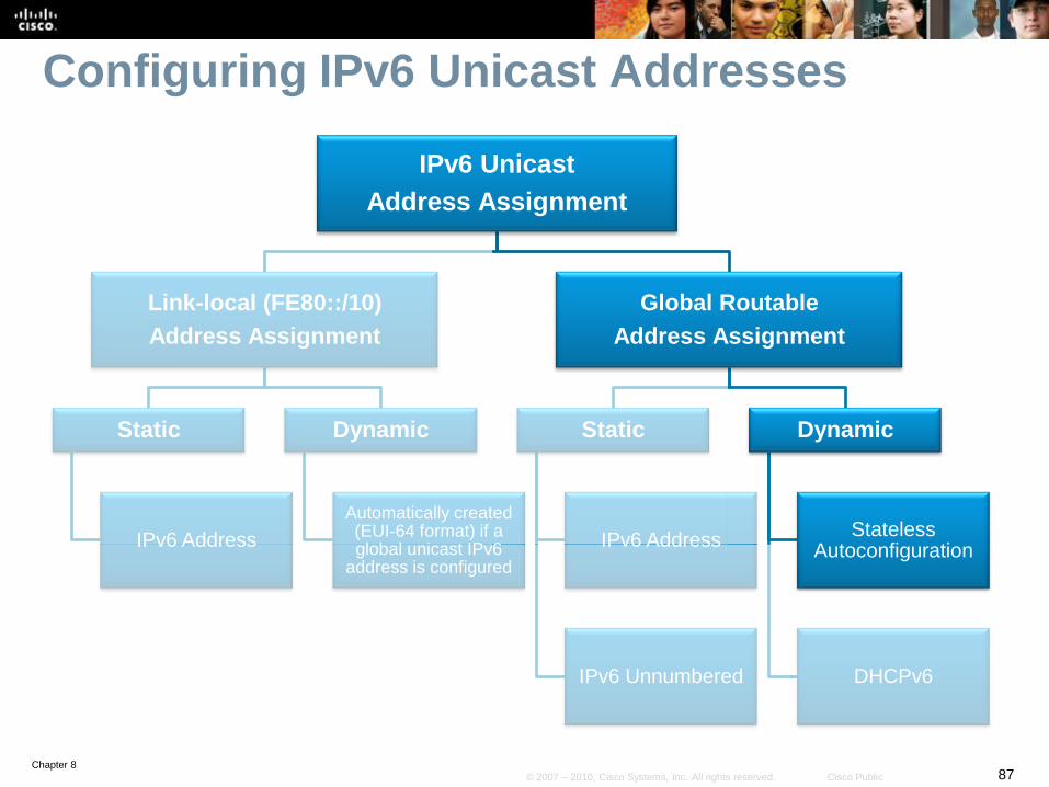
Configuring IPv6 Unicast Addresses
IPv6 Unicast
Address Assignment
Link-local (FE80::/10)
Address Assignment
Static
IPv6 Address
Dynamic
Automatically created (EUI-64 format) if a global unicast IPv6
address is configured
Global Routable
Address Assignment
Static
IPv6 Address
IPv6 Unnumbered
Dynamic
Stateless Autoconfiguration
DHCPv6
Chapter 871© 2007 – 2010, Cisco Systems, Inc. All rights reserved. Cisco Public
IPv6 Unicast
Address Assignment
Link-local (FE80::/10)
Address Assignment
Static
IPv6 Address
Dynamic
Automatically created (EUI-64 format) if a global unicast IPv6
address is configured
Global Routable
Address Assignment
Static
IPv6 Address
IPv6 Unnumbered
Dynamic
Stateless Autoconfiguration
DHCPv6
Configuring IPv6 Unicast Addresses
Chapter 872© 2007 – 2010, Cisco Systems, Inc. All rights reserved. Cisco Public
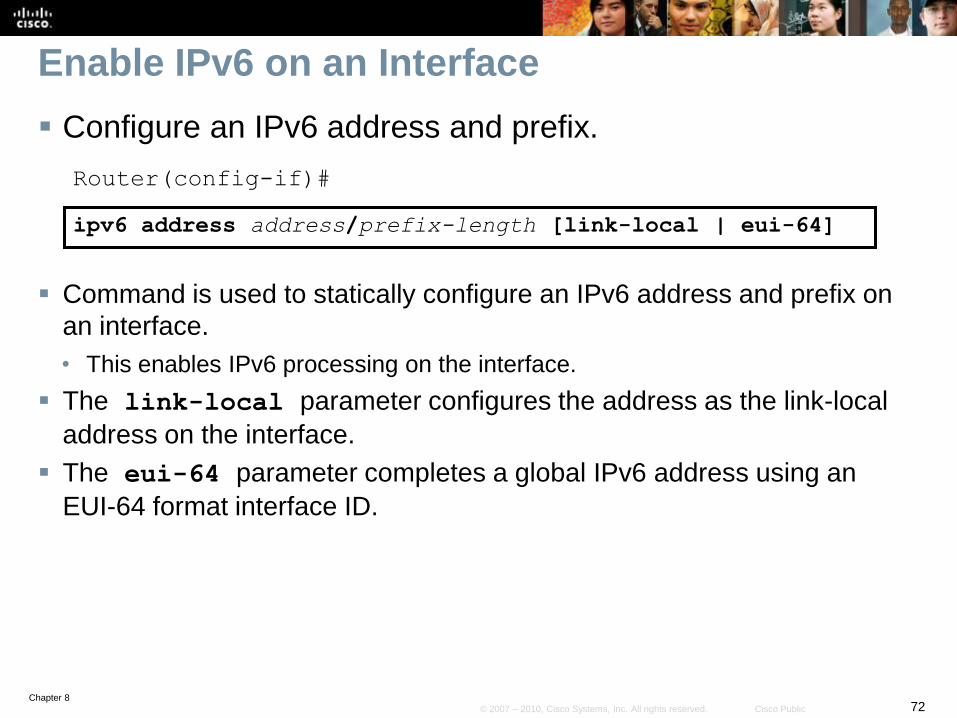
Enable IPv6 on an Interface
Configure an IPv6 address and prefix.
Router(config-if)#
ipv6 address address/prefix-length [link-local | eui-64]
Command is used to statically configure an IPv6 address and prefix on
an interface.
• This enables IPv6 processing on the interface.
The link-local parameter configures the address as the link-local
address on the interface.
The eui-64 parameter completes a global IPv6 address using an
EUI-64 format interface ID.
Chapter 873© 2007 – 2010, Cisco Systems, Inc. All rights reserved. Cisco Public
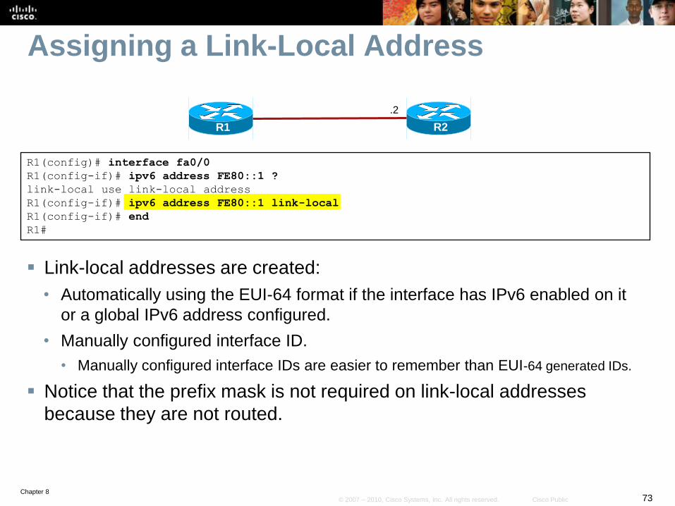
Assigning a Link-Local Address
Link-local addresses are created:
• Automatically using the EUI-64 format if the interface has IPv6 enabled on it
or a global IPv6 address configured.
• Manually configured interface ID.
• Manually configured interface IDs are easier to remember than EUI-64 generated IDs.
Notice that the prefix mask is not required on link-local addresses
because they are not routed.
R2R1
.2
R1(config)# interface fa0/0
R1(config-if)# ipv6 address FE80::1 ?
link-local use link-local address
R1(config-if)# ipv6 address FE80::1 link-local
R1(config-if)# end
R1#
Chapter 874© 2007 – 2010, Cisco Systems, Inc. All rights reserved. Cisco Public
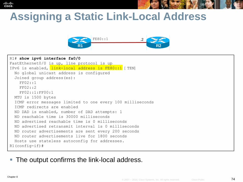
Assigning a Static Link-Local Address
The output confirms the link-local address.
R2
FE80::1
R1
.2
R1# show ipv6 interface fa0/0
FastEthernet0/0 is up, line protocol is up
IPv6 is enabled, link-local address is FE80::1 [TEN]
No global unicast address is configured
Joined group address(es):
FF02::1
FF02::2
FF02::1:FF00:1
MTU is 1500 bytes
ICMP error messages limited to one every 100 milliseconds
ICMP redirects are enabled
ND DAD is enabled, number of DAD attempts: 1
ND reachable time is 30000 milliseconds
ND advertised reachable time is 0 milliseconds
ND advertised retransmit interval is 0 milliseconds
ND router advertisements are sent every 200 seconds
ND router advertisements live for 1800 seconds
Hosts use stateless autoconfig for addresses.
R1(config-if)#
Chapter 875© 2007 – 2010, Cisco Systems, Inc. All rights reserved. Cisco Public
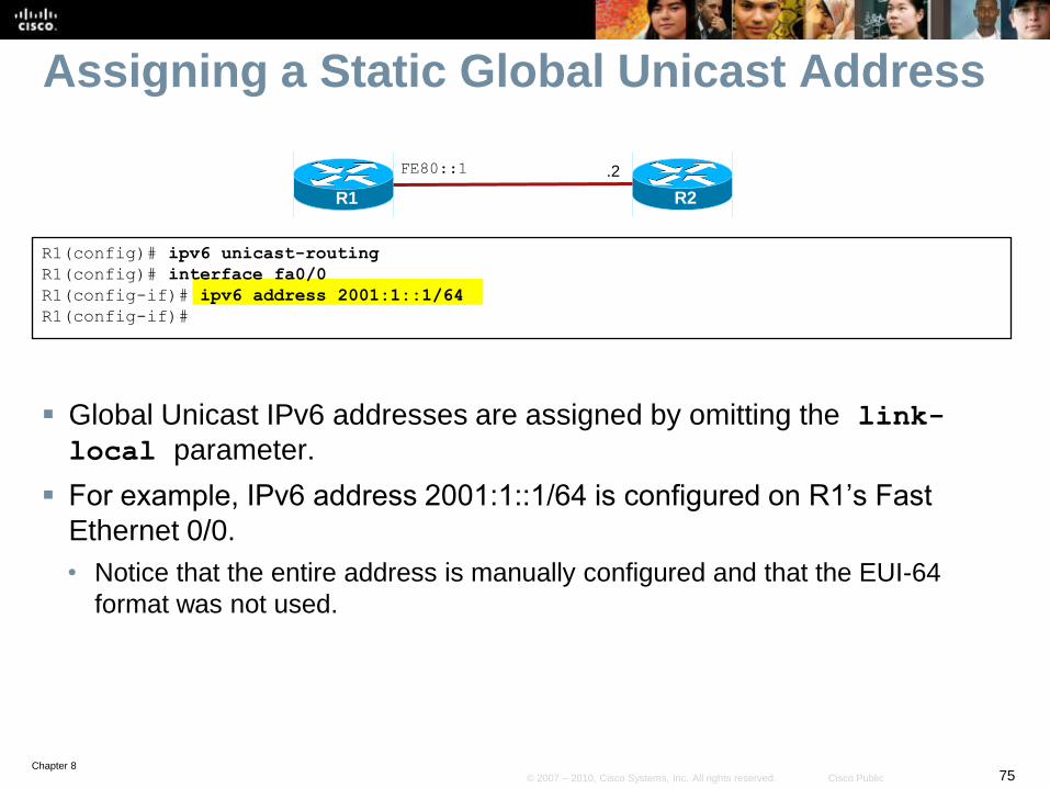
Assigning a Static Global Unicast Address
Global Unicast IPv6 addresses are assigned by omitting the link-
local parameter.
For example, IPv6 address 2001:1::1/64 is configured on R1’s Fast
Ethernet 0/0.
• Notice that the entire address is manually configured and that the EUI-64
format was not used.
R2R1
.2
R1(config)# ipv6 unicast-routing
R1(config)# interface fa0/0
R1(config-if)# ipv6 address 2001:1::1/64
R1(config-if)#
FE80::1
Chapter 876© 2007 – 2010, Cisco Systems, Inc. All rights reserved. Cisco Public
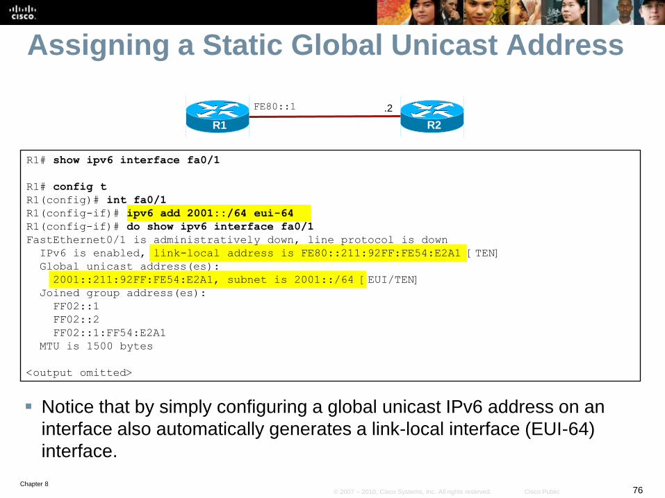
Assigning a Static Global Unicast Address
Notice that by simply configuring a global unicast IPv6 address on an
interface also automatically generates a link-local interface (EUI-64)
interface.
R2R1
.2FE80::1
R1# show ipv6 interface fa0/1
R1# config t
R1(config)# int fa0/1
R1(config-if)# ipv6 add 2001::/64 eui-64
R1(config-if)# do show ipv6 interface fa0/1
FastEthernet0/1 is administratively down, line protocol is down
IPv6 is enabled, link-local address is FE80::211:92FF:FE54:E2A1 [TEN]
Global unicast address(es):
2001::211:92FF:FE54:E2A1, subnet is 2001::/64 [EUI/TEN]
Joined group address(es):
FF02::1
FF02::2
FF02::1:FF54:E2A1
MTU is 1500 bytes
<output omitted>
Chapter 877© 2007 – 2010, Cisco Systems, Inc. All rights reserved. Cisco Public
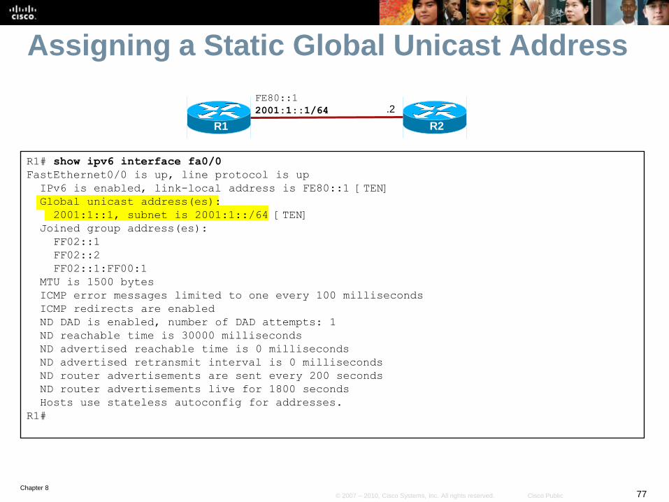
Assigning a Static Global Unicast Address
R2
FE80::1
2001:1::1/64
R1
.2
R1# show ipv6 interface fa0/0
FastEthernet0/0 is up, line protocol is up
IPv6 is enabled, link-local address is FE80::1 [TEN]
Global unicast address(es):
2001:1::1, subnet is 2001:1::/64 [TEN]
Joined group address(es):
FF02::1
FF02::2
FF02::1:FF00:1
MTU is 1500 bytes
ICMP error messages limited to one every 100 milliseconds
ICMP redirects are enabled
ND DAD is enabled, number of DAD attempts: 1
ND reachable time is 30000 milliseconds
ND advertised reachable time is 0 milliseconds
ND advertised retransmit interval is 0 milliseconds
ND router advertisements are sent every 200 seconds
ND router advertisements live for 1800 seconds
Hosts use stateless autoconfig for addresses.
R1#
Chapter 878© 2007 – 2010, Cisco Systems, Inc. All rights reserved. Cisco Public
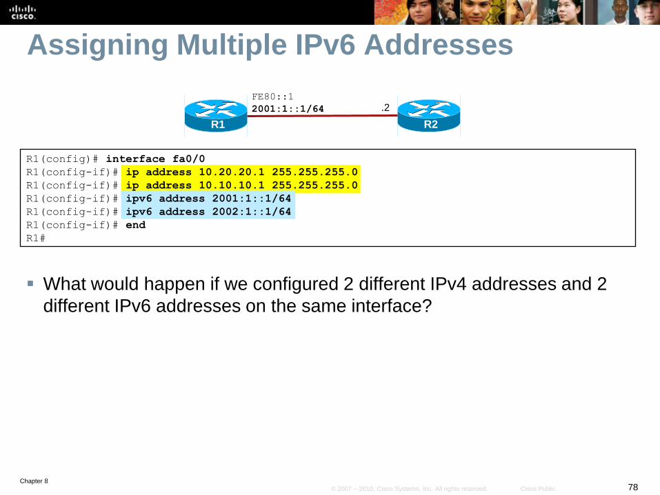
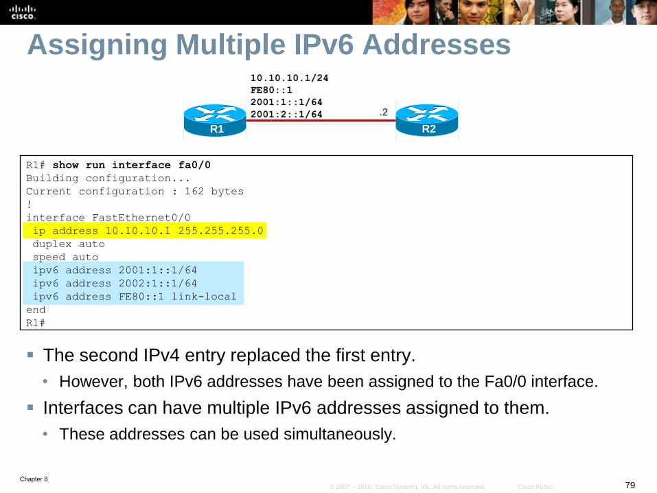
Assigning Multiple IPv6 Addresses
What would happen if we configured 2 different IPv4 addresses and 2
different IPv6 addresses on the same interface?
R2R1
.2
R1(config)# interface fa0/0
R1(config-if)# ip address 10.20.20.1 255.255.255.0
R1(config-if)# ip address 10.10.10.1 255.255.255.0
R1(config-if)# ipv6 address 2001:1::1/64
R1(config-if)# ipv6 address 2002:1::1/64
R1(config-if)# end
R1#
FE80::1
2001:1::1/64
Chapter 879© 2007 – 2010, Cisco Systems, Inc. All rights reserved. Cisco Public
Assigning Multiple IPv6 Addresses
The second IPv4 entry replaced the first entry.
• However, both IPv6 addresses have been assigned to the Fa0/0 interface.
Interfaces can have multiple IPv6 addresses assigned to them.
• These addresses can be used simultaneously.
R2R1
.2
R1# show run interface fa0/0
Building configuration...
Current configuration : 162 bytes
!
interface FastEthernet0/0
ip address 10.10.10.1 255.255.255.0
duplex auto
speed auto
ipv6 address 2001:1::1/64
ipv6 address 2002:1::1/64
ipv6 address FE80::1 link-local
end
R1#
10.10.10.1/24
FE80::1
2001:1::1/64
2001:2::1/64

Chapter 880© 2007 – 2010, Cisco Systems, Inc. All rights reserved. Cisco Public
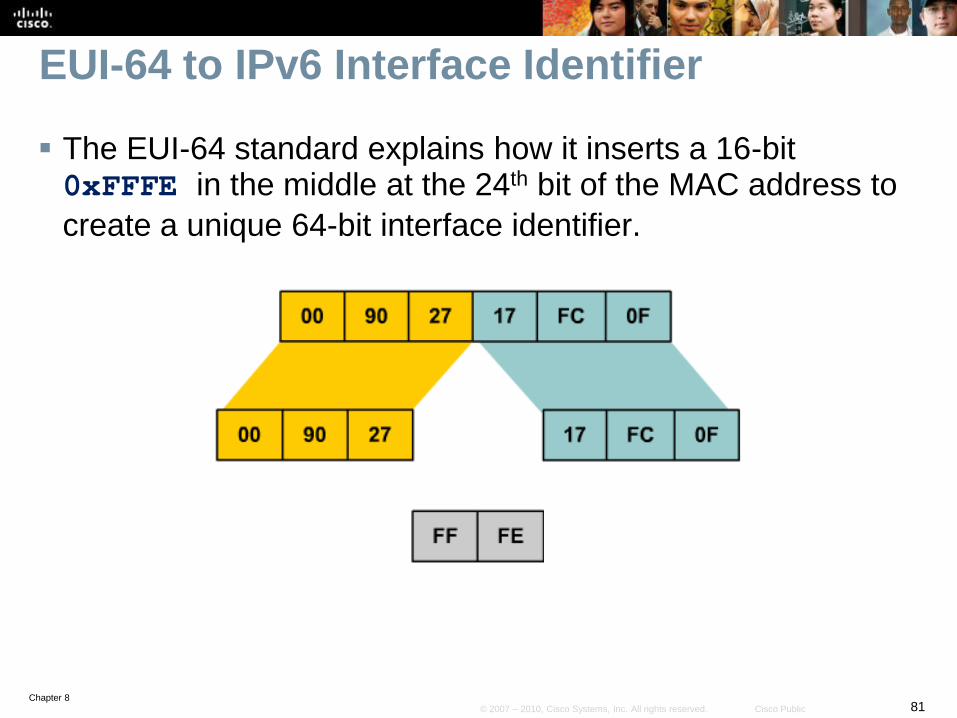
Ethernet EUI-64 Address
EUI-64 IPv6 addresses are addresses where the first 64
bits are the network portion of the address and specified,
and the interface ID (second 64-bits) are the host portion of
the address and automatically generated by the router.
The interface ID on an Ethernet link is based on the 48-bit
MAC address of the interface with an additional 16-bit 0xFFFE inserted in the middle of the MAC address.
• This creates an extended unique identifier referred to as the EUI-64
format.
• The seventh bit in the high-order byte is set to 1 to indicate the
uniqueness of the interface ID.
Chapter 881© 2007 – 2010, Cisco Systems, Inc. All rights reserved. Cisco Public
EUI-64 to IPv6 Interface Identifier
The EUI-64 standard explains how it inserts a 16-bit 0xFFFE in the middle at the 24th bit of the MAC address to
create a unique 64-bit interface identifier.
Chapter 882© 2007 – 2010, Cisco Systems, Inc. All rights reserved. Cisco Public
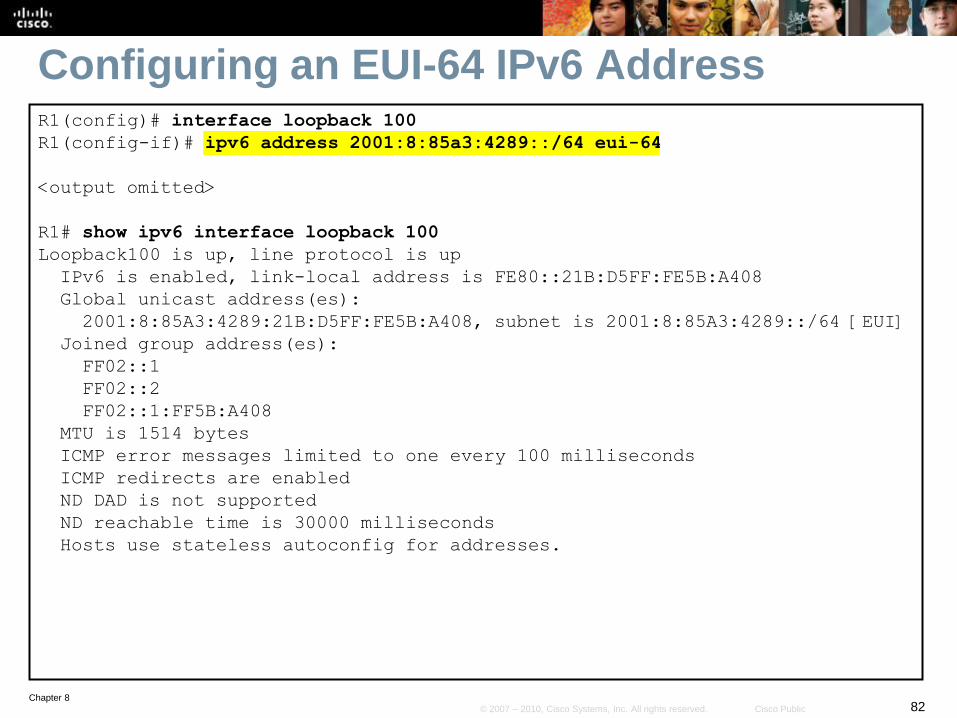
Configuring an EUI-64 IPv6 AddressR1(config)# interface loopback 100
R1(config-if)# ipv6 address 2001:8:85a3:4289::/64 eui-64
<output omitted>
R1# show ipv6 interface loopback 100
Loopback100 is up, line protocol is up
IPv6 is enabled, link-local address is FE80::21B:D5FF:FE5B:A408
Global unicast address(es):
2001:8:85A3:4289:21B:D5FF:FE5B:A408, subnet is 2001:8:85A3:4289::/64 [EUI]
Joined group address(es):
FF02::1
FF02::2
FF02::1:FF5B:A408
MTU is 1514 bytes
ICMP error messages limited to one every 100 milliseconds
ICMP redirects are enabled
ND DAD is not supported
ND reachable time is 30000 milliseconds
Hosts use stateless autoconfig for addresses.
Chapter 883© 2007 – 2010, Cisco Systems, Inc. All rights reserved. Cisco Public
IPv6 Unicast
Address Assignment
Link-local (FE80::/10)
Address Assignment
Static
IPv6 Address
Dynamic
Automatically created (EUI-64 format) if a global unicast IPv6
address is configured
Global Routable
Address Assignment
Static
IPv6 Address
IPv6 Unnumbered
Dynamic
Stateless Autoconfiguration
DHCPv6
Configuring IPv6 Unicast Addresses
Chapter 884© 2007 – 2010, Cisco Systems, Inc. All rights reserved. Cisco Public
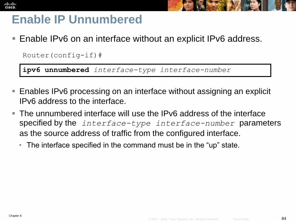
Enable IP Unnumbered
Enable IPv6 on an interface without an explicit IPv6 address.
Router(config-if)#
ipv6 unnumbered interface-type interface-number
Enables IPv6 processing on an interface without assigning an explicit
IPv6 address to the interface.
The unnumbered interface will use the IPv6 address of the interface specified by the interface-type interface-number parameters
as the source address of traffic from the configured interface.
• The interface specified in the command must be in the “up” state.
Chapter 885© 2007 – 2010, Cisco Systems, Inc. All rights reserved. Cisco Public
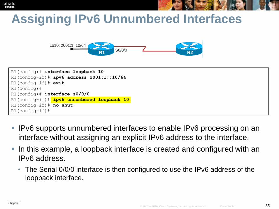
Assigning IPv6 Unnumbered Interfaces
IPv6 supports unnumbered interfaces to enable IPv6 processing on an
interface without assigning an explicit IPv6 address to the interface.
In this example, a loopback interface is created and configured with an
IPv6 address.
• The Serial 0/0/0 interface is then configured to use the IPv6 address of the
loopback interface.
S0/0/0
R1(config)# interface loopback 10
R1(config-if)# ipv6 address 2001:1::10/64
R1(config-if)# exit
R1(config)#
R1(config)# interface s0/0/0
R1(config-if)# ipv6 unnumbered loopback 10
R1(config-if)# no shut
R1(config-if)#
R1
Lo10: 2001:1::10/64
R2
Chapter 886© 2007 – 2010, Cisco Systems, Inc. All rights reserved. Cisco Public
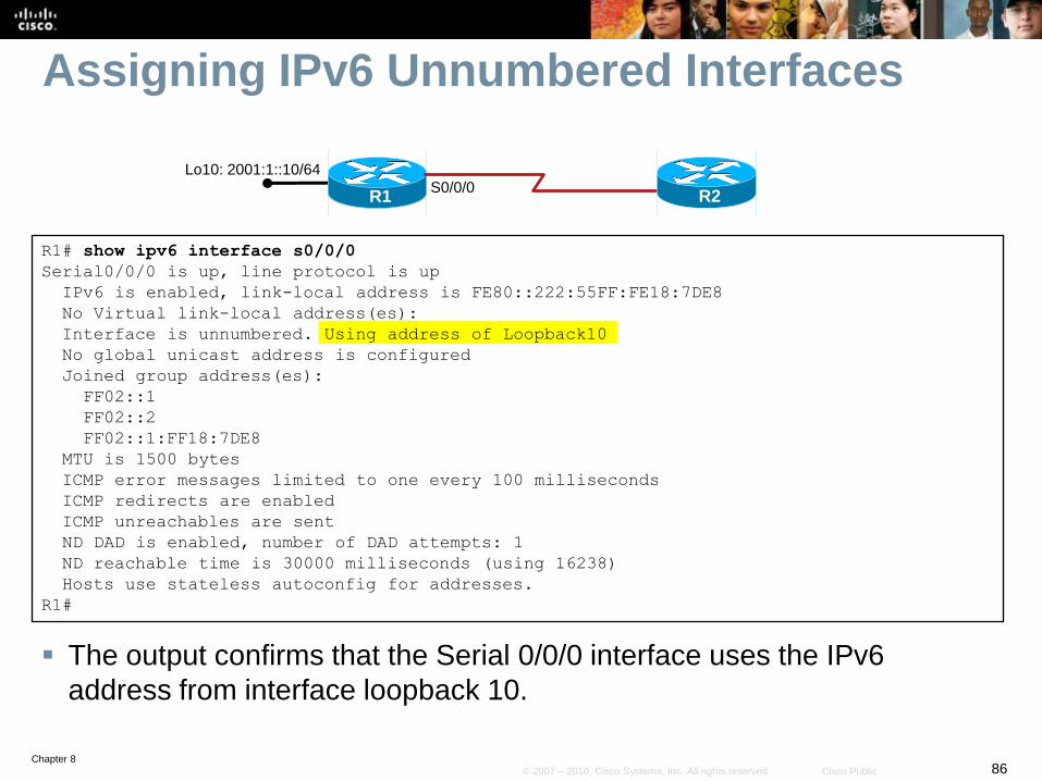
Assigning IPv6 Unnumbered Interfaces
The output confirms that the Serial 0/0/0 interface uses the IPv6
address from interface loopback 10.
R1# show ipv6 interface s0/0/0
Serial0/0/0 is up, line protocol is up
IPv6 is enabled, link-local address is FE80::222:55FF:FE18:7DE8
No Virtual link-local address(es):
Interface is unnumbered. Using address of Loopback10
No global unicast address is configured
Joined group address(es):
FF02::1
FF02::2
FF02::1:FF18:7DE8
MTU is 1500 bytes
ICMP error messages limited to one every 100 milliseconds
ICMP redirects are enabled
ICMP unreachables are sent
ND DAD is enabled, number of DAD attempts: 1
ND reachable time is 30000 milliseconds (using 16238)
Hosts use stateless autoconfig for addresses.
R1#
S0/0/0R1
Lo10: 2001:1::10/64
R2
Chapter 887© 2007 – 2010, Cisco Systems, Inc. All rights reserved. Cisco Public
IPv6 Unicast
Address Assignment
Link-local (FE80::/10)
Address Assignment
Static
IPv6 Address
Dynamic
Automatically created (EUI-64 format) if a global unicast IPv6
address is configured
Global Routable
Address Assignment
Static
IPv6 Address
IPv6 Unnumbered
Dynamic
Stateless Autoconfiguration
DHCPv6
Configuring IPv6 Unicast Addresses
Chapter 888© 2007 – 2010, Cisco Systems, Inc. All rights reserved. Cisco Public
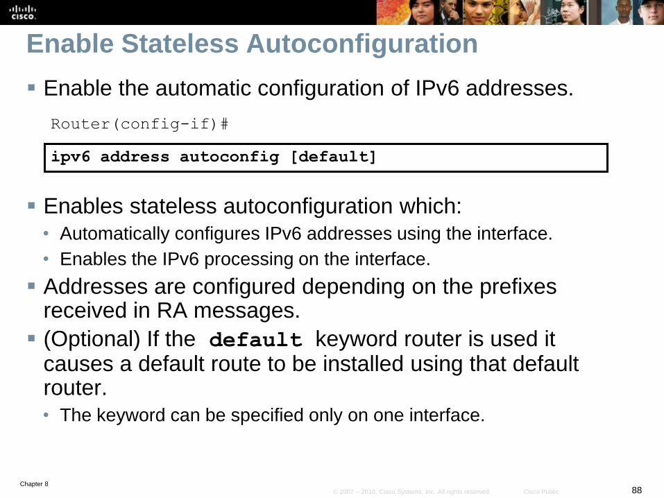
Enable Stateless Autoconfiguration
Enable the automatic configuration of IPv6 addresses.
Router(config-if)#
ipv6 address autoconfig [default]
Enables stateless autoconfiguration which:
• Automatically configures IPv6 addresses using the interface.
• Enables the IPv6 processing on the interface.
Addresses are configured depending on the prefixes received in RA messages.
(Optional) If the default keyword router is used it causes a default route to be installed using that default router.
• The keyword can be specified only on one interface.
Chapter 889© 2007 – 2010, Cisco Systems, Inc. All rights reserved. Cisco Public
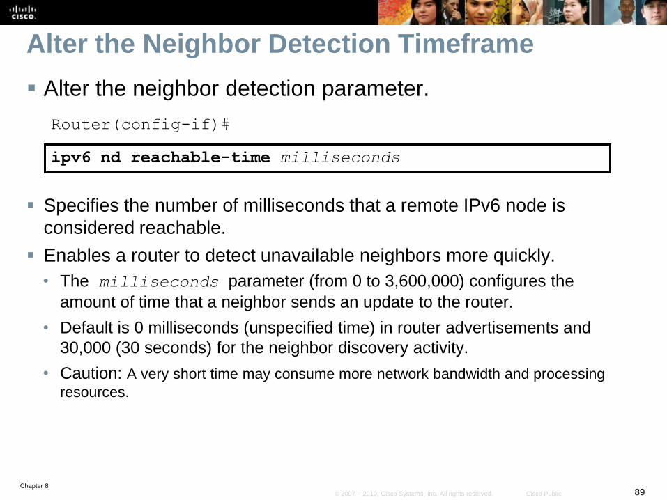
Alter the Neighbor Detection Timeframe
Alter the neighbor detection parameter.
Router(config-if)#
ipv6 nd reachable-time milliseconds
Specifies the number of milliseconds that a remote IPv6 node is
considered reachable.
Enables a router to detect unavailable neighbors more quickly.
• The milliseconds parameter (from 0 to 3,600,000) configures the
amount of time that a neighbor sends an update to the router.
• Default is 0 milliseconds (unspecified time) in router advertisements and
30,000 (30 seconds) for the neighbor discovery activity.
• Caution: A very short time may consume more network bandwidth and processing
resources.
Chapter 890© 2007 – 2010, Cisco Systems, Inc. All rights reserved. Cisco Public
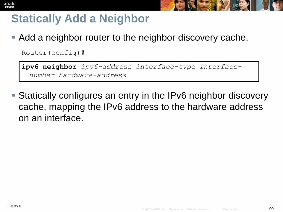
Statically Add a Neighbor
Add a neighbor router to the neighbor discovery cache.
Router(config)#
ipv6 neighbor ipv6-address interface-type interface-
number hardware-address
Statically configures an entry in the IPv6 neighbor discovery
cache, mapping the IPv6 address to the hardware address
on an interface.
Chapter 891© 2007 – 2010, Cisco Systems, Inc. All rights reserved. Cisco Public
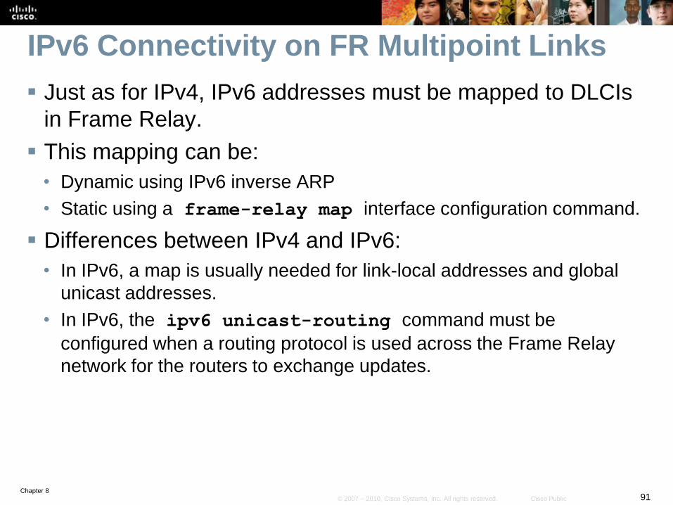
IPv6 Connectivity on FR Multipoint Links
Just as for IPv4, IPv6 addresses must be mapped to DLCIs
in Frame Relay.
This mapping can be:
• Dynamic using IPv6 inverse ARP
• Static using a frame-relay map interface configuration command.
Differences between IPv4 and IPv6:
• In IPv6, a map is usually needed for link-local addresses and global
unicast addresses.
• In IPv6, the ipv6 unicast-routing command must be
configured when a routing protocol is used across the Frame Relay
network for the routers to exchange updates.
Chapter 892© 2007 – 2010, Cisco Systems, Inc. All rights reserved. Cisco Public
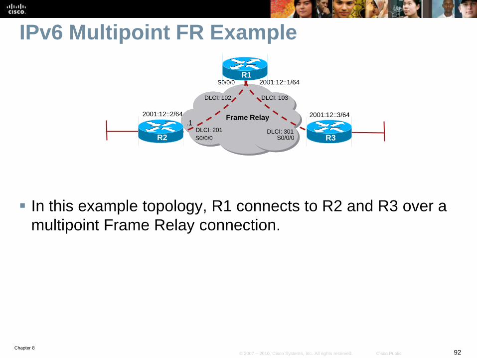
IPv6 Multipoint FR Example
In this example topology, R1 connects to R2 and R3 over a
multipoint Frame Relay connection.
Frame Relay
2001:12::1/64
.1
R2 R3
R1
2001:12::3/642001:12::2/64
DLCI: 103
DLCI: 301DLCI: 201
DLCI: 102
S0/0/0 S0/0/0
S0/0/0
Chapter 893© 2007 – 2010, Cisco Systems, Inc. All rights reserved. Cisco Public
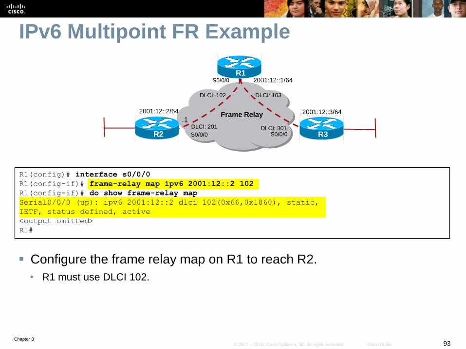
IPv6 Multipoint FR Example
Configure the frame relay map on R1 to reach R2.
• R1 must use DLCI 102.
R1(config)# interface s0/0/0
R1(config-if)# frame-relay map ipv6 2001:12::2 102
R1(config-if)# do show frame-relay map
Serial0/0/0 (up): ipv6 2001:12::2 dlci 102(0x66,0x1860), static,
IETF, status defined, active
<output omitted>
R1#
Frame Relay
2001:12::1/64
.1
R2 R3
R1
2001:12::3/642001:12::2/64
DLCI: 103
DLCI: 301DLCI: 201
DLCI: 102
S0/0/0 S0/0/0
S0/0/0
Chapter 894© 2007 – 2010, Cisco Systems, Inc. All rights reserved. Cisco Public
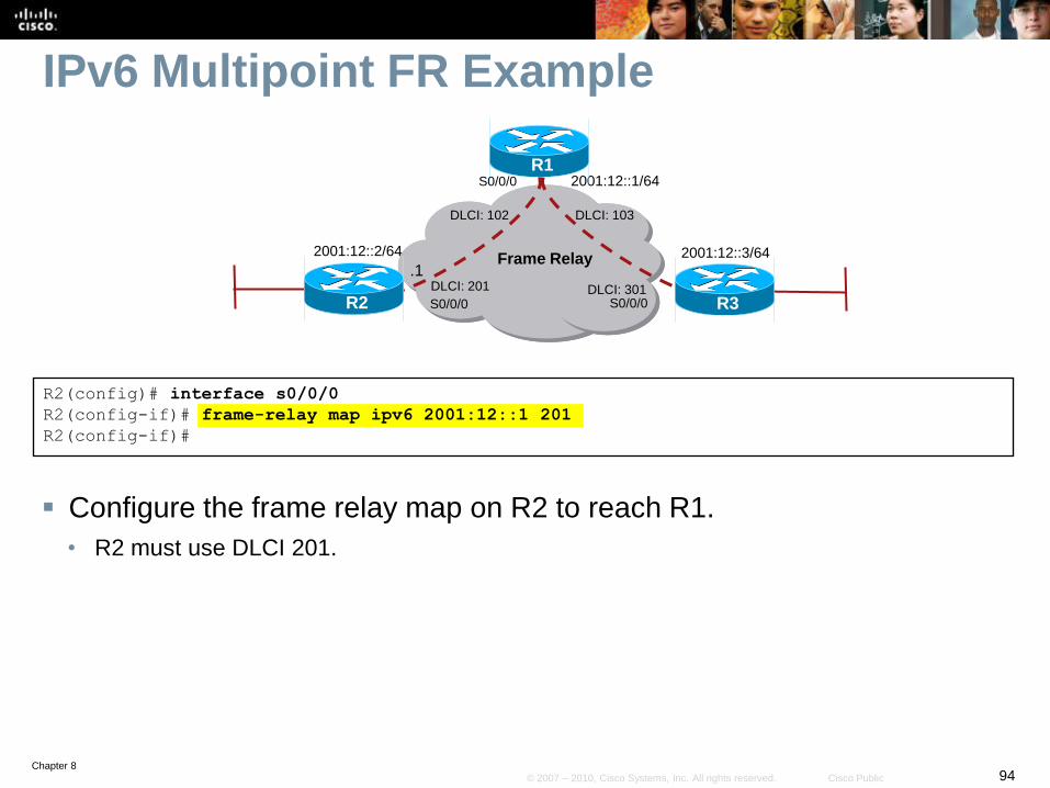
IPv6 Multipoint FR Example
Configure the frame relay map on R2 to reach R1.
• R2 must use DLCI 201.
R2(config)# interface s0/0/0
R2(config-if)# frame-relay map ipv6 2001:12::1 201
R2(config-if)#
Frame Relay
2001:12::1/64
.1
R2 R3
R1
2001:12::3/642001:12::2/64
DLCI: 103
DLCI: 301DLCI: 201
DLCI: 102
S0/0/0 S0/0/0
S0/0/0
Chapter 895© 2007 – 2010, Cisco Systems, Inc. All rights reserved. Cisco Public
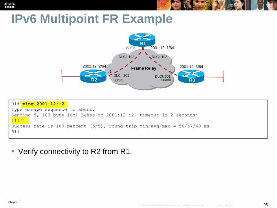
IPv6 Multipoint FR Example
Verify connectivity to R2 from R1.
R1# ping 2001:12::2
Type escape sequence to abort.
Sending 5, 100-byte ICMP Echos to 2001:12::2, timeout is 2 seconds:
!!!!!
Success rate is 100 percent (5/5), round-trip min/avg/max = 56/57/60 ms
R1#
Frame Relay
2001:12::1/64
.1
R2 R3
R1
2001:12::3/642001:12::2/64
DLCI: 103
DLCI: 301DLCI: 201
DLCI: 102
S0/0/0 S0/0/0
S0/0/0
Chapter 896© 2007 – 2010, Cisco Systems, Inc. All rights reserved. Cisco Public
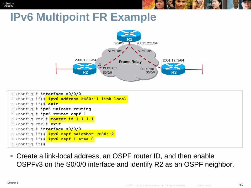
IPv6 Multipoint FR Example
Create a link-local address, an OSPF router ID, and then enable
OSPFv3 on the S0/0/0 interface and identify R2 as an OSPF neighbor.
R1(config)# interface s0/0/0
R1(config-if)# ipv6 address FE80::1 link-local
R1(config-if)# exit
R1(config)# ipv6 unicast-routing
R1(config)# ipv6 router ospf 1
R1(config-rtr)# router-id 1.1.1.1
R1(config-rtr)# exit
R1(config)# interface s0/0/0
R1(config-if)# ipv6 ospf neighbor FE80::2
R1(config-if)# ipv6 ospf 1 area 0
R1(config-if)#
Frame Relay
2001:12::1/64
.1
R2 R3
R1
2001:12::3/642001:12::2/64
DLCI: 103
DLCI: 301DLCI: 201
DLCI: 102
S0/0/0 S0/0/0
S0/0/0
Chapter 897© 2007 – 2010, Cisco Systems, Inc. All rights reserved. Cisco Public
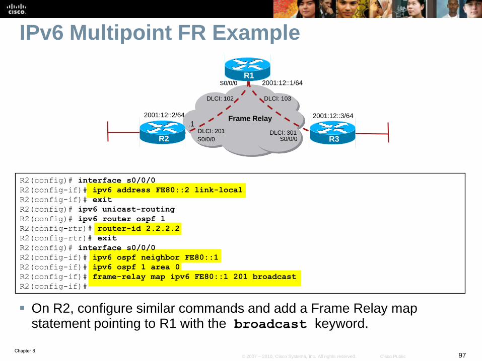
IPv6 Multipoint FR Example
On R2, configure similar commands and add a Frame Relay map statement pointing to R1 with the broadcast keyword.
R2(config)# interface s0/0/0
R2(config-if)# ipv6 address FE80::2 link-local
R2(config-if)# exit
R2(config)# ipv6 unicast-routing
R2(config)# ipv6 router ospf 1
R2(config-rtr)# router-id 2.2.2.2
R2(config-rtr)# exit
R2(config)# interface s0/0/0
R2(config-if)# ipv6 ospf neighbor FE80::1
R2(config-if)# ipv6 ospf 1 area 0
R2(config-if)# frame-relay map ipv6 FE80::1 201 broadcast
R2(config-if)#
Frame Relay
2001:12::1/64
.1
R2 R3
R1
2001:12::3/642001:12::2/64
DLCI: 103
DLCI: 301DLCI: 201
DLCI: 102
S0/0/0 S0/0/0
S0/0/0
Chapter 898© 2007 – 2010, Cisco Systems, Inc. All rights reserved. Cisco Public
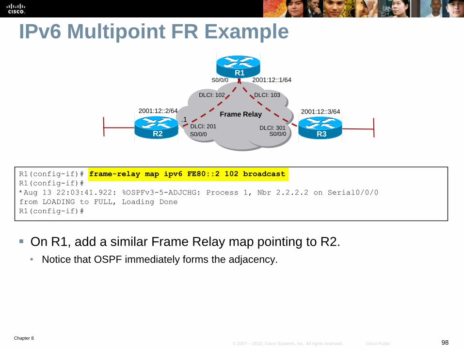
IPv6 Multipoint FR Example
On R1, add a similar Frame Relay map pointing to R2.
• Notice that OSPF immediately forms the adjacency.
R1(config-if)# frame-relay map ipv6 FE80::2 102 broadcast
R1(config-if)#
*Aug 13 22:03:41.922: %OSPFv3-5-ADJCHG: Process 1, Nbr 2.2.2.2 on Serial0/0/0
from LOADING to FULL, Loading Done
R1(config-if)#
Frame Relay
2001:12::1/64
.1
R2 R3
R1
2001:12::3/642001:12::2/64
DLCI: 103
DLCI: 301DLCI: 201
DLCI: 102
S0/0/0 S0/0/0
S0/0/0

Chapter 899© 2007 – 2010, Cisco Systems, Inc. All rights reserved. Cisco Public
Routing IPv6 Traffic
Chapter 8100© 2007 – 2010, Cisco Systems, Inc. All rights reserved. Cisco Public
IPv6 Routing
IPv6 supports the following routing:
• Static Routing
• RIPng
• OSPFv3
• IS-IS for IPv6
• EIGRP for IPv6
• Multiprotocol BGP version 4 (MP-BGPv4)
For each routing option above, the ipv6 unicast-
routing command must be configured.
Chapter 8101© 2007 – 2010, Cisco Systems, Inc. All rights reserved. Cisco Public
Configuring Static Routing
Chapter 8102© 2007 – 2010, Cisco Systems, Inc. All rights reserved. Cisco Public
Static Routing
Configured in the same way as IPv4.
There is an IPv6-specific requirement per RFC 2461.
• A router must be able to determine the link-local address of each of its
neighboring routers to ensure that the target address of a redirect
message identifies the neighbor router by its link-local address.
• This requirement basically means that using a global unicast address
as a next-hop address with routing is not recommended.
Chapter 8103© 2007 – 2010, Cisco Systems, Inc. All rights reserved. Cisco Public
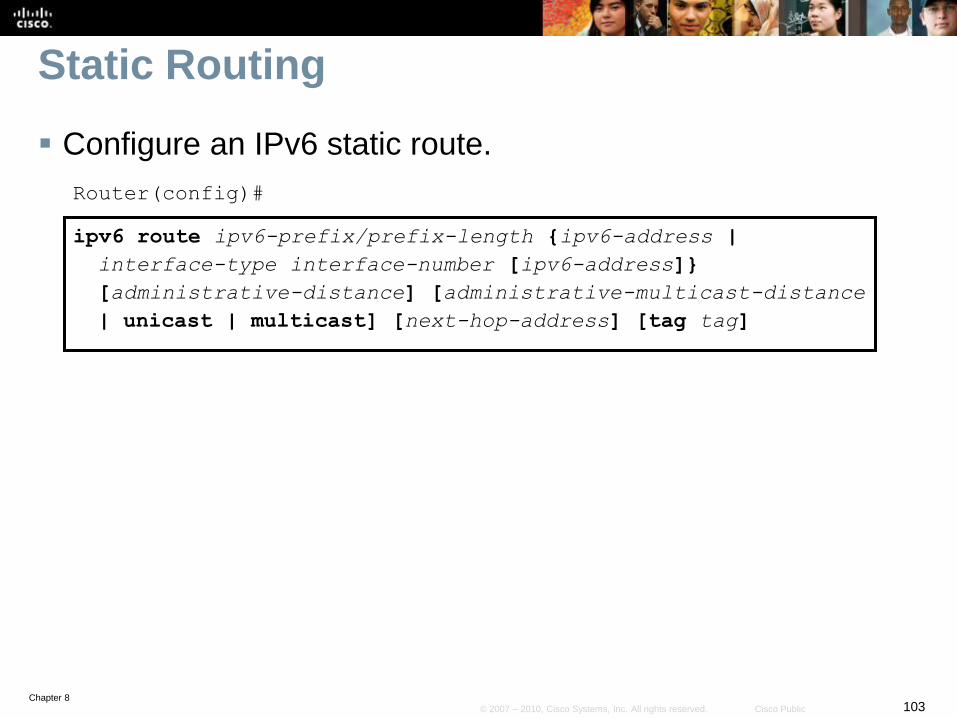
Static Routing
Configure an IPv6 static route.
Router(config)#
ipv6 route ipv6-prefix/prefix-length {ipv6-address |
interface-type interface-number [ipv6-address]}
[administrative-distance] [administrative-multicast-distance
| unicast | multicast] [next-hop-address] [tag tag]
Chapter 8104© 2007 – 2010, Cisco Systems, Inc. All rights reserved. Cisco Public
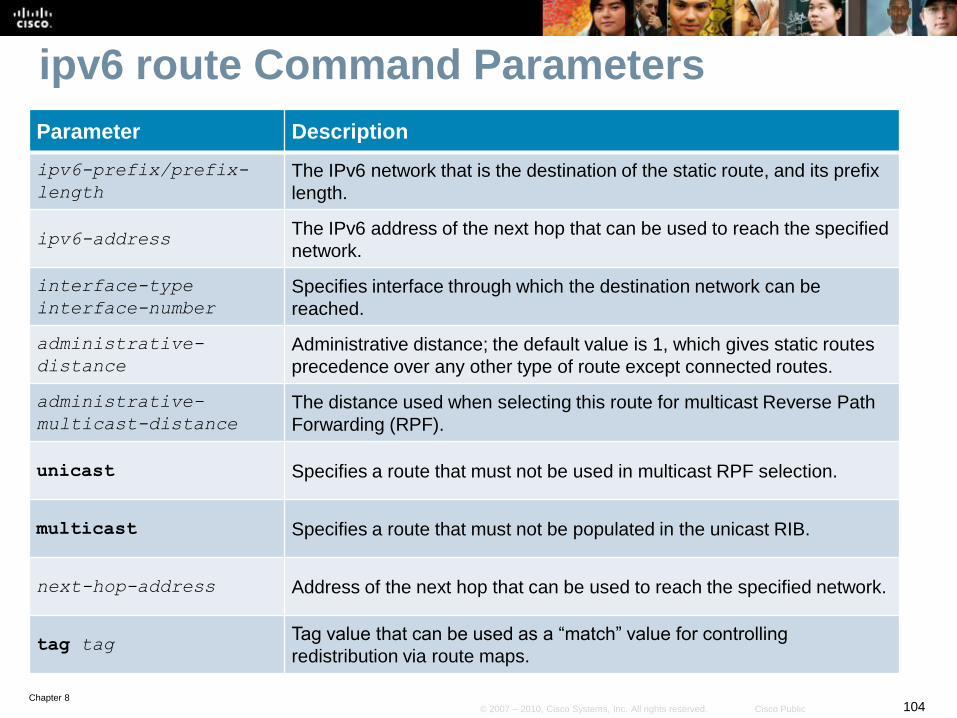
ipv6 route Command Parameters
Parameter Description
ipv6-prefix/prefix-
length
The IPv6 network that is the destination of the static route, and its prefix
length.
ipv6-addressThe IPv6 address of the next hop that can be used to reach the specified
network.
interface-type
interface-number
Specifies interface through which the destination network can be
reached.
administrative-
distance
Administrative distance; the default value is 1, which gives static routes
precedence over any other type of route except connected routes.
administrative-
multicast-distance
The distance used when selecting this route for multicast Reverse Path
Forwarding (RPF).
unicast Specifies a route that must not be used in multicast RPF selection.
multicast Specifies a route that must not be populated in the unicast RIB.
next-hop-address Address of the next hop that can be used to reach the specified network.
tag tagTag value that can be used as a “match” value for controlling
redistribution via route maps.
Chapter 8105© 2007 – 2010, Cisco Systems, Inc. All rights reserved. Cisco Public
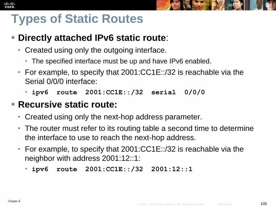
Types of Static Routes
Directly attached IPv6 static route:
• Created using only the outgoing interface.
• The specified interface must be up and have IPv6 enabled.
• For example, to specify that 2001:CC1E::/32 is reachable via the
Serial 0/0/0 interface:
• ipv6 route 2001:CC1E::/32 serial 0/0/0
Recursive static route:
• Created using only the next-hop address parameter.
• The router must refer to its routing table a second time to determine
the interface to use to reach the next-hop address.
• For example, to specify that 2001:CC1E::/32 is reachable via the
neighbor with address 2001:12::1:
• ipv6 route 2001:CC1E::/32 2001:12::1
Chapter 8106© 2007 – 2010, Cisco Systems, Inc. All rights reserved. Cisco Public
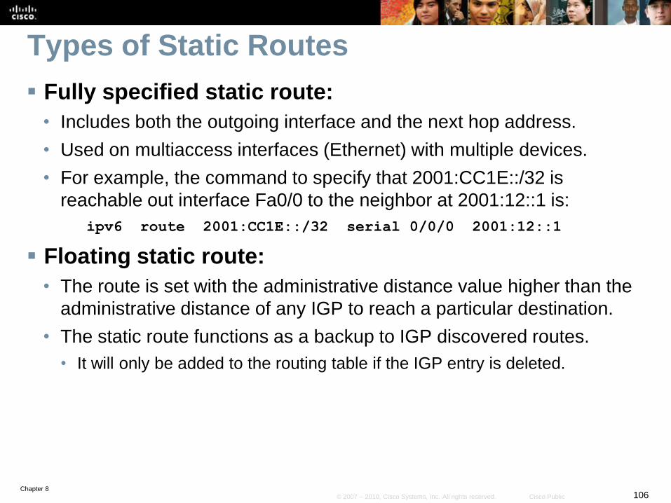
Types of Static Routes
Fully specified static route:
• Includes both the outgoing interface and the next hop address.
• Used on multiaccess interfaces (Ethernet) with multiple devices.
• For example, the command to specify that 2001:CC1E::/32 is
reachable out interface Fa0/0 to the neighbor at 2001:12::1 is:
ipv6 route 2001:CC1E::/32 serial 0/0/0 2001:12::1
Floating static route:
• The route is set with the administrative distance value higher than the
administrative distance of any IGP to reach a particular destination.
• The static route functions as a backup to IGP discovered routes.
• It will only be added to the routing table if the IGP entry is deleted.
Chapter 8107© 2007 – 2010, Cisco Systems, Inc. All rights reserved. Cisco Public
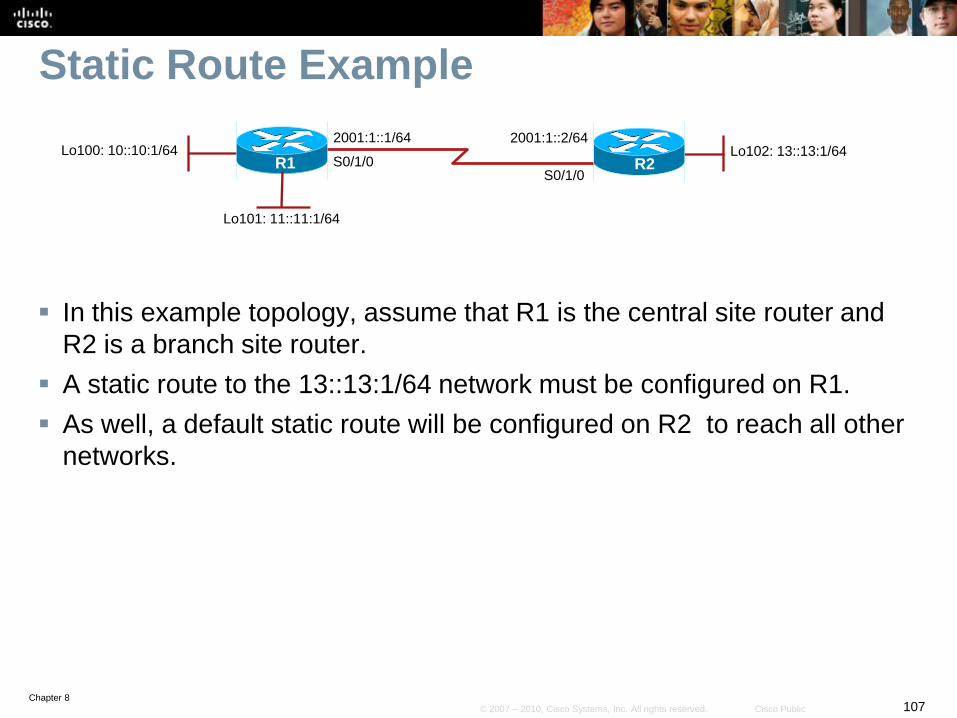
Static Route Example
In this example topology, assume that R1 is the central site router and
R2 is a branch site router.
A static route to the 13::13:1/64 network must be configured on R1.
As well, a default static route will be configured on R2 to reach all other
networks.
2001:1::1/64
S0/1/0S0/1/0
R1Lo102: 13::13:1/64
2001:1::2/64
R2Lo100: 10::10:1/64
Lo101: 11::11:1/64
Chapter 8108© 2007 – 2010, Cisco Systems, Inc. All rights reserved. Cisco Public
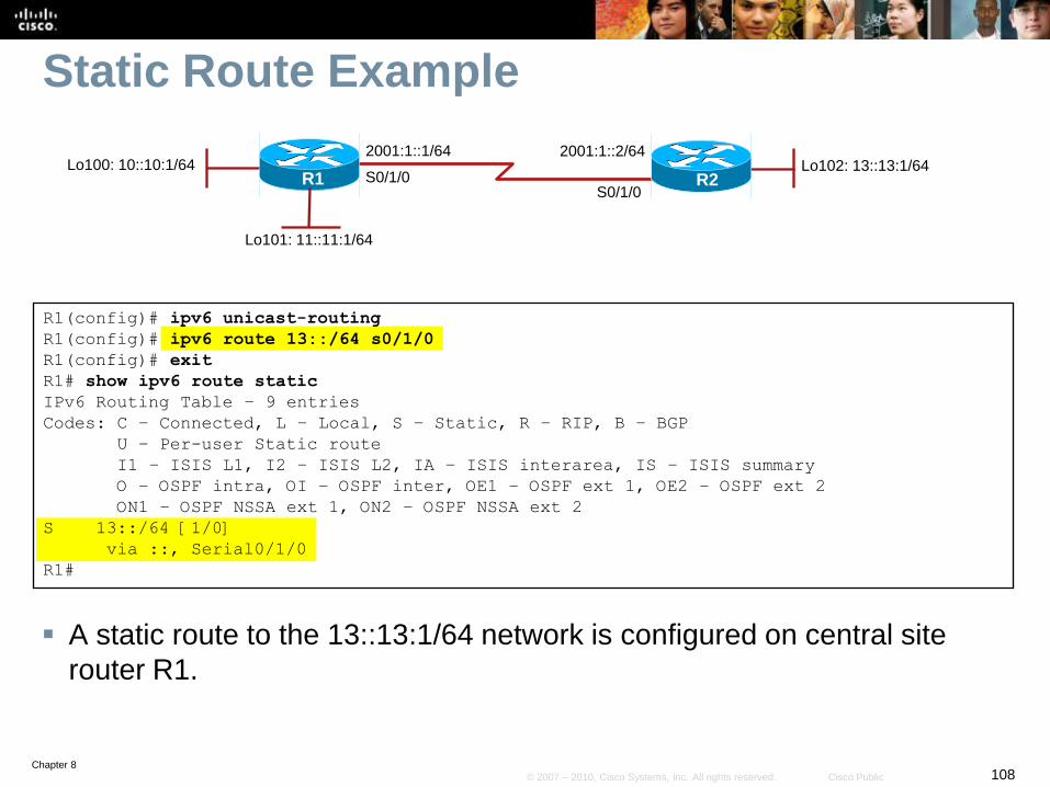
Static Route Example
A static route to the 13::13:1/64 network is configured on central site
router R1.
R1(config)# ipv6 unicast-routing
R1(config)# ipv6 route 13::/64 s0/1/0
R1(config)# exit
R1# show ipv6 route static
IPv6 Routing Table – 9 entries
Codes: C – Connected, L – Local, S – Static, R – RIP, B – BGP
U – Per-user Static route
I1 – ISIS L1, I2 – ISIS L2, IA – ISIS interarea, IS – ISIS summary
O – OSPF intra, OI – OSPF inter, OE1 – OSPF ext 1, OE2 – OSPF ext 2
ON1 – OSPF NSSA ext 1, ON2 – OSPF NSSA ext 2
S 13::/64 [1/0]
via ::, Serial0/1/0
R1#
2001:1::1/64
S0/1/0S0/1/0
R1Lo102: 13::13:1/64
2001:1::2/64
R2Lo100: 10::10:1/64
Lo101: 11::11:1/64
Chapter 8109© 2007 – 2010, Cisco Systems, Inc. All rights reserved. Cisco Public
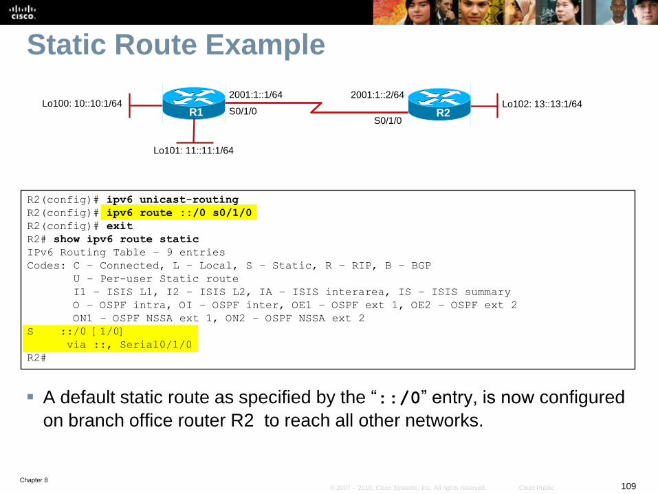
Static Route Example
A default static route as specified by the “::/0” entry, is now configured
on branch office router R2 to reach all other networks.
R2(config)# ipv6 unicast-routing
R2(config)# ipv6 route ::/0 s0/1/0
R2(config)# exit
R2# show ipv6 route static
IPv6 Routing Table – 9 entries
Codes: C – Connected, L – Local, S – Static, R – RIP, B – BGP
U – Per-user Static route
I1 – ISIS L1, I2 – ISIS L2, IA – ISIS interarea, IS – ISIS summary
O – OSPF intra, OI – OSPF inter, OE1 – OSPF ext 1, OE2 – OSPF ext 2
ON1 – OSPF NSSA ext 1, ON2 – OSPF NSSA ext 2
S ::/0 [1/0]
via ::, Serial0/1/0
R2#
2001:1::1/64
S0/1/0S0/1/0
R1Lo102: 13::13:1/64
2001:1::2/64
R2Lo100: 10::10:1/64
Lo101: 11::11:1/64
Chapter 8110© 2007 – 2010, Cisco Systems, Inc. All rights reserved. Cisco Public
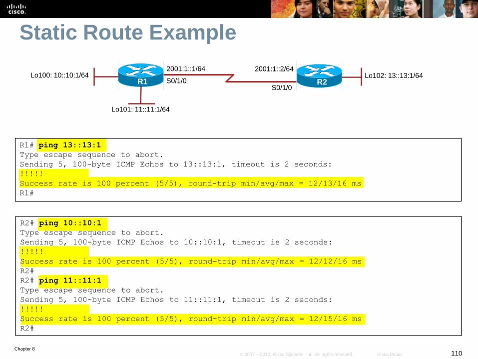
Static Route Example
R1# ping 13::13:1
Type escape sequence to abort.
Sending 5, 100-byte ICMP Echos to 13::13:1, timeout is 2 seconds:
!!!!!
Success rate is 100 percent (5/5), round-trip min/avg/max = 12/13/16 ms
R1#
R2# ping 10::10:1
Type escape sequence to abort.
Sending 5, 100-byte ICMP Echos to 10::10:1, timeout is 2 seconds:
!!!!!
Success rate is 100 percent (5/5), round-trip min/avg/max = 12/12/16 ms
R2#
R2# ping 11::11:1
Type escape sequence to abort.
Sending 5, 100-byte ICMP Echos to 11::11:1, timeout is 2 seconds:
!!!!!
Success rate is 100 percent (5/5), round-trip min/avg/max = 12/15/16 ms
R2#
2001:1::1/64
S0/1/0S0/1/0
R1Lo102: 13::13:1/64
2001:1::2/64
R2Lo100: 10::10:1/64
Lo101: 11::11:1/64
Chapter 8111© 2007 – 2010, Cisco Systems, Inc. All rights reserved. Cisco Public
RIPng
Routing Information Protocol next generation (RIPng, RFC
2080) is a distance vector routing protocol for IPv6.
• It’s based on IPv4 RIP version 2 (RIPv2).
It is similar to RIPv2 because:
• The hop limit is still 15.
• The administrative distance is still 120.
• It still uses split horizon and poison reverse to prevent routing loops.
Unlike RIPv2, RIPng is:
• Used to transport IPv6 networks and prefixes.
• It uses an IPv6 prefix and a next-hop IPv6 address.
• Uses UDP port 520 (instead of UDP port 521).
• Uses the multicast group FF02::9 (instead of 224.0.0.9).
Chapter 8112© 2007 – 2010, Cisco Systems, Inc. All rights reserved. Cisco Public
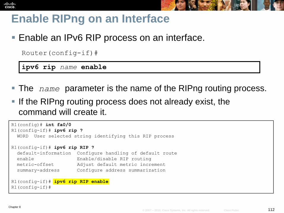
Enable RIPng on an Interface
Enable an IPv6 RIP process on an interface.
Router(config-if)#
ipv6 rip name enable
The name parameter is the name of the RIPng routing process.
If the RIPng routing process does not already exist, the
command will create it.
R1(config)# int fa0/0
R1(config-if)# ipv6 rip ?
WORD User selected string identifying this RIP process
R1(config-if)# ipv6 rip RIP ?
default-information Configure handling of default route
enable Enable/disable RIP routing
metric-offset Adjust default metric increment
summary-address Configure address summarization
R1(config-if)# ipv6 rip RIP enable
R1(config-if)#
Chapter 8113© 2007 – 2010, Cisco Systems, Inc. All rights reserved. Cisco Public
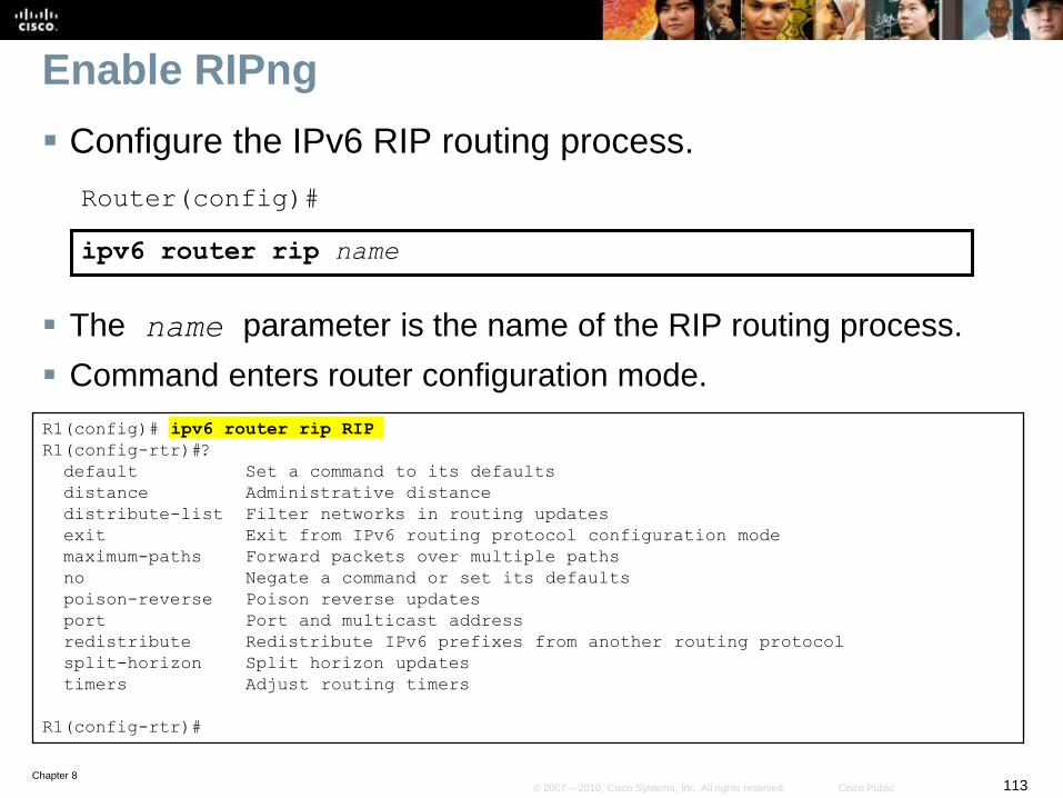
Enable RIPng
Configure the IPv6 RIP routing process.
Router(config)#
ipv6 router rip name
The name parameter is the name of the RIP routing process.
Command enters router configuration mode.
R1(config)# ipv6 router rip RIP
R1(config-rtr)#?
default Set a command to its defaults
distance Administrative distance
distribute-list Filter networks in routing updates
exit Exit from IPv6 routing protocol configuration mode
maximum-paths Forward packets over multiple paths
no Negate a command or set its defaults
poison-reverse Poison reverse updates
port Port and multicast address
redistribute Redistribute IPv6 prefixes from another routing protocol
split-horizon Split horizon updates
timers Adjust routing timers
R1(config-rtr)#
Chapter 8114© 2007 – 2010, Cisco Systems, Inc. All rights reserved. Cisco Public
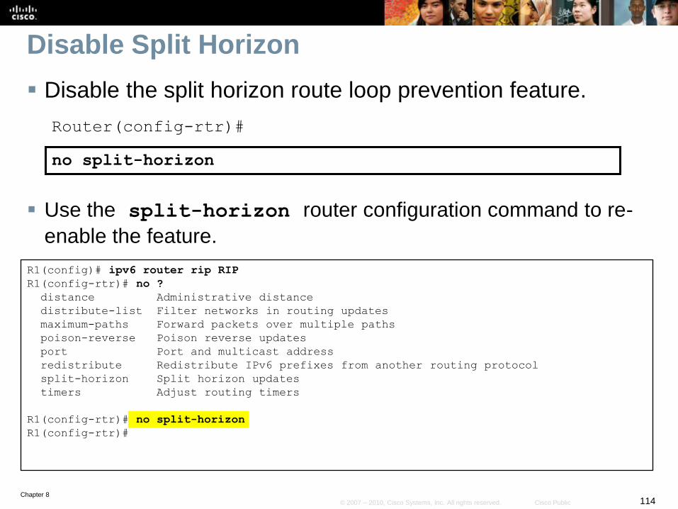
Disable Split Horizon
Disable the split horizon route loop prevention feature.
Router(config-rtr)#
no split-horizon
Use the split-horizon router configuration command to re-
enable the feature.
R1(config)# ipv6 router rip RIP
R1(config-rtr)# no ?
distance Administrative distance
distribute-list Filter networks in routing updates
maximum-paths Forward packets over multiple paths
poison-reverse Poison reverse updates
port Port and multicast address
redistribute Redistribute IPv6 prefixes from another routing protocol
split-horizon Split horizon updates
timers Adjust routing timers
R1(config-rtr)# no split-horizon
R1(config-rtr)#
Chapter 8115© 2007 – 2010, Cisco Systems, Inc. All rights reserved. Cisco Public
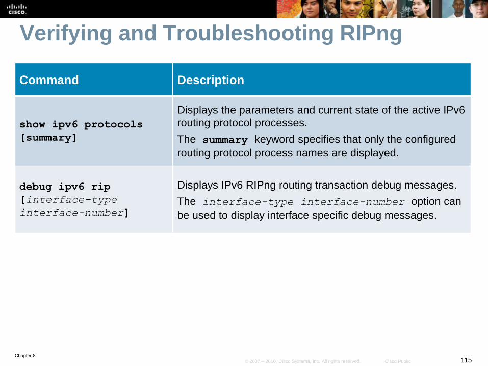
Verifying and Troubleshooting RIPng
Command Description
show ipv6 protocols
[summary]
Displays the parameters and current state of the active IPv6
routing protocol processes.
The summary keyword specifies that only the configured
routing protocol process names are displayed.
debug ipv6 rip
[interface-type
interface-number]
Displays IPv6 RIPng routing transaction debug messages.
The interface-type interface-number option can
be used to display interface specific debug messages.
Chapter 8116© 2007 – 2010, Cisco Systems, Inc. All rights reserved. Cisco Public
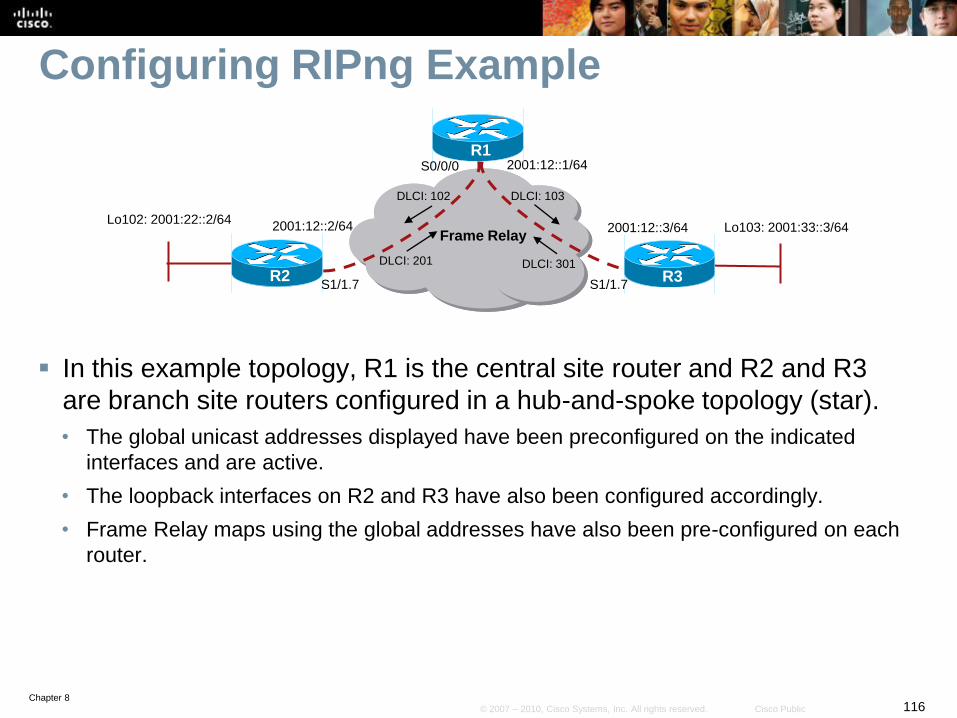
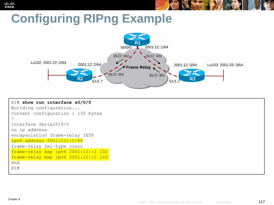
Configuring RIPng Example
In this example topology, R1 is the central site router and R2 and R3
are branch site routers configured in a hub-and-spoke topology (star).
• The global unicast addresses displayed have been preconfigured on the indicated
interfaces and are active.
• The loopback interfaces on R2 and R3 have also been configured accordingly.
• Frame Relay maps using the global addresses have also been pre-configured on each
router.
Frame Relay
2001:12::1/64
R2 R3
R1
2001:12::3/642001:12::2/64
DLCI: 103
DLCI: 301DLCI: 201
DLCI: 102
S0/0/0
S1/1.7 S1/1.7
Lo103: 2001:33::3/64Lo102: 2001:22::2/64
Chapter 8117© 2007 – 2010, Cisco Systems, Inc. All rights reserved. Cisco Public
Configuring RIPng Example
R1# show run interface s0/0/0
Building configuration...
Current configuration : 132 bytes
!
interface Serial0/0/0
no ip address
encapsulation frame-relay IETF
ipv6 address 2001:12::1/64
frame-relay lmi-type cisco
frame-relay map ipv6 2001:12::2 102
frame-relay map ipv6 2001:12::3 103
end
R1#
Frame Relay
2001:12::1/64
R2 R3
R1
2001:12::3/642001:12::2/64
DLCI: 103
DLCI: 301DLCI: 201
DLCI: 102
S0/0/0
S1/1.7 S1/1.7
Lo103: 2001:33::3/64Lo102: 2001:22::2/64
Chapter 8118© 2007 – 2010, Cisco Systems, Inc. All rights reserved. Cisco Public
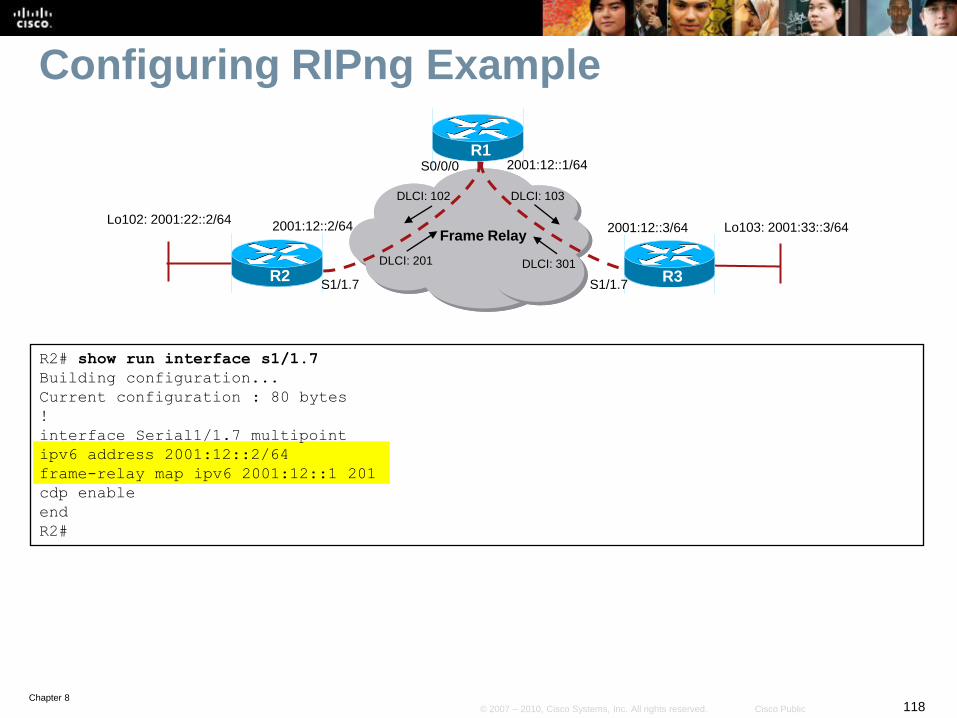
Configuring RIPng Example
R2# show run interface s1/1.7
Building configuration...
Current configuration : 80 bytes
!
interface Serial1/1.7 multipoint
ipv6 address 2001:12::2/64
frame-relay map ipv6 2001:12::1 201
cdp enable
end
R2#
Frame Relay
2001:12::1/64
R2 R3
R1
2001:12::3/642001:12::2/64
DLCI: 103
DLCI: 301DLCI: 201
DLCI: 102
S0/0/0
S1/1.7 S1/1.7
Lo103: 2001:33::3/64Lo102: 2001:22::2/64
Chapter 8119© 2007 – 2010, Cisco Systems, Inc. All rights reserved. Cisco Public
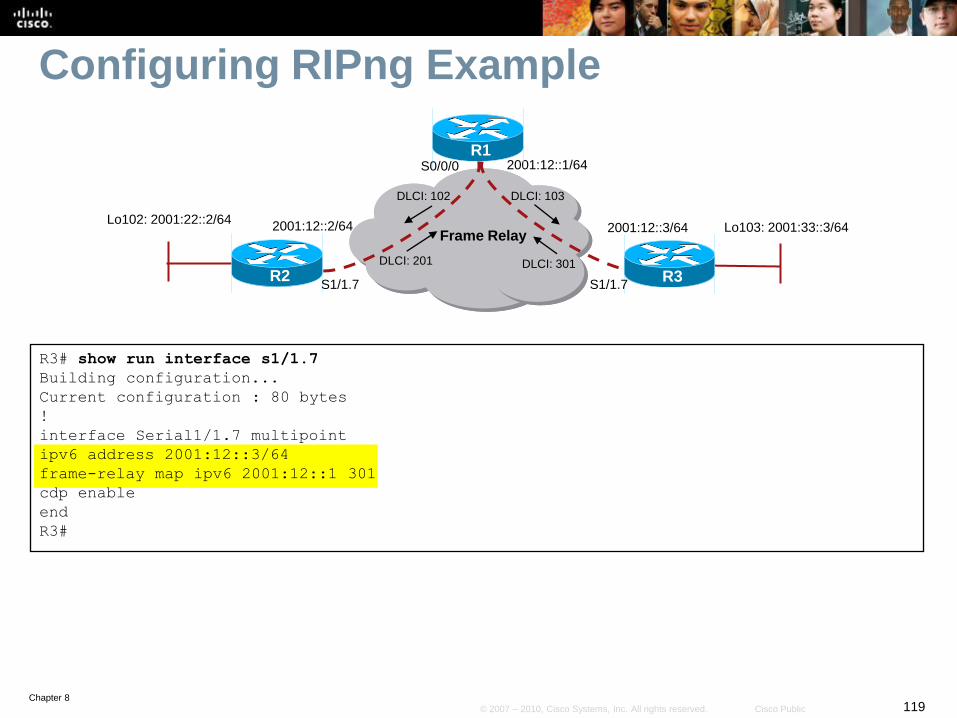
Configuring RIPng Example
R3# show run interface s1/1.7
Building configuration...
Current configuration : 80 bytes
!
interface Serial1/1.7 multipoint
ipv6 address 2001:12::3/64
frame-relay map ipv6 2001:12::1 301
cdp enable
end
R3#
Frame Relay
2001:12::1/64
R2 R3
R1
2001:12::3/642001:12::2/64
DLCI: 103
DLCI: 301DLCI: 201
DLCI: 102
S0/0/0
S1/1.7 S1/1.7
Lo103: 2001:33::3/64Lo102: 2001:22::2/64
Chapter 8120© 2007 – 2010, Cisco Systems, Inc. All rights reserved. Cisco Public
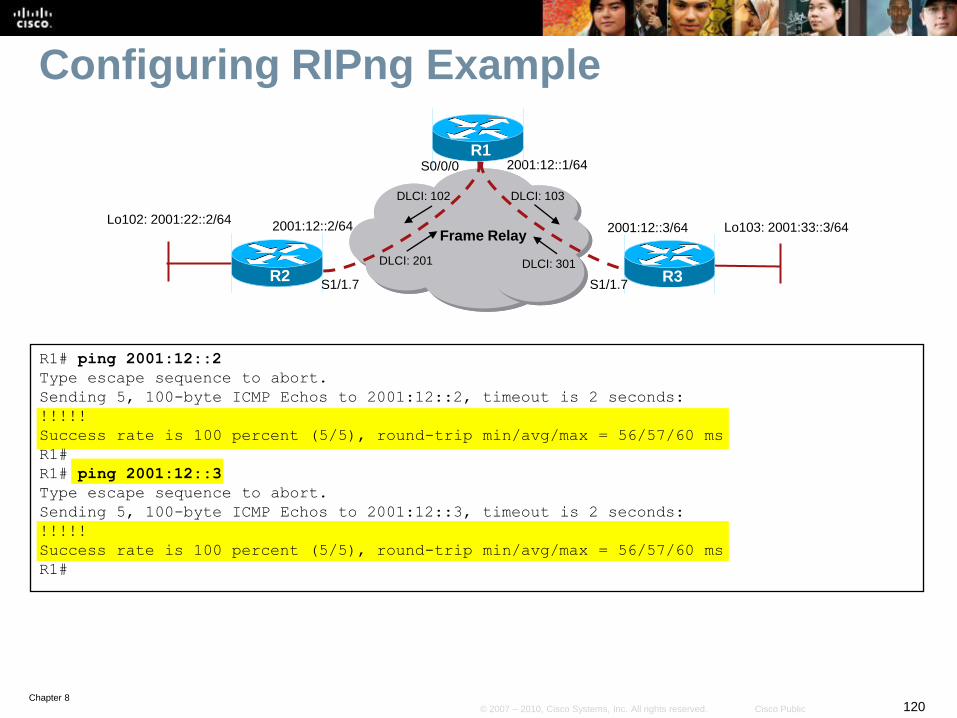
Configuring RIPng Example
R1# ping 2001:12::2
Type escape sequence to abort.
Sending 5, 100-byte ICMP Echos to 2001:12::2, timeout is 2 seconds:
!!!!!
Success rate is 100 percent (5/5), round-trip min/avg/max = 56/57/60 ms
R1#
R1# ping 2001:12::3
Type escape sequence to abort.
Sending 5, 100-byte ICMP Echos to 2001:12::3, timeout is 2 seconds:
!!!!!
Success rate is 100 percent (5/5), round-trip min/avg/max = 56/57/60 ms
R1#
Frame Relay
2001:12::1/64
R2 R3
R1
2001:12::3/642001:12::2/64
DLCI: 103
DLCI: 301DLCI: 201
DLCI: 102
S0/0/0
S1/1.7 S1/1.7
Lo103: 2001:33::3/64Lo102: 2001:22::2/64
Chapter 8121© 2007 – 2010, Cisco Systems, Inc. All rights reserved. Cisco Public
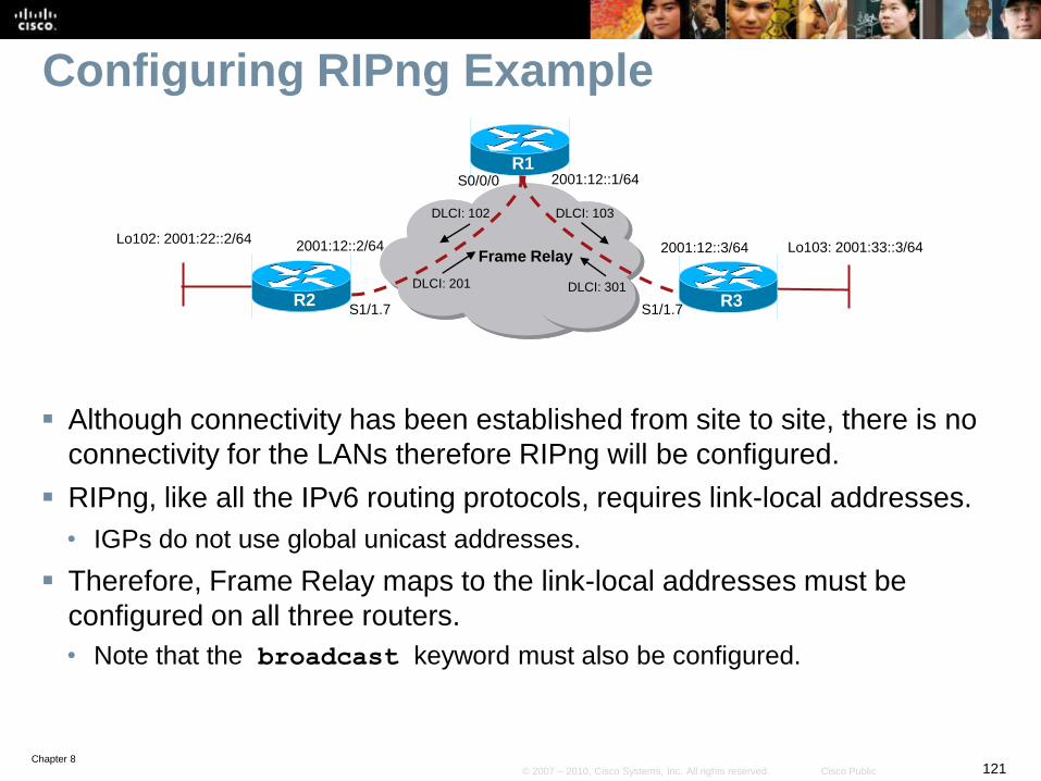
Configuring RIPng Example
Although connectivity has been established from site to site, there is no
connectivity for the LANs therefore RIPng will be configured.
RIPng, like all the IPv6 routing protocols, requires link-local addresses.
• IGPs do not use global unicast addresses.
Therefore, Frame Relay maps to the link-local addresses must be
configured on all three routers.
• Note that the broadcast keyword must also be configured.
Frame Relay
2001:12::1/64
R2 R3
R1
2001:12::3/642001:12::2/64
DLCI: 103
DLCI: 301DLCI: 201
DLCI: 102
S0/0/0
S1/1.7 S1/1.7
Lo103: 2001:33::3/64Lo102: 2001:22::2/64
Chapter 8122© 2007 – 2010, Cisco Systems, Inc. All rights reserved. Cisco Public
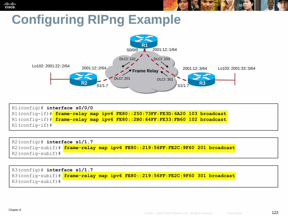
Configuring RIPng Example
R1(config)# interface s0/0/0
R1(config-if)# frame-relay map ipv6 FE80::250:73FF:FE3D:6A20 103 broadcast
R1(config-if)# frame-relay map ipv6 FE80::2B0:64FF:FE33:FB60 102 broadcast
R1(config-if)#
R2(config)# interface s1/1.7
R2(config-subif)# frame-relay map ipv6 FE80::219:56FF:FE2C:9F60 201 broadcast
R2(config-subif)#
R3(config)# interface s1/1.7
R3(config-subif)# frame-relay map ipv6 FE80::219:56FF:FE2C:9F60 301 broadcast
R3(config-subif)#
Frame Relay
2001:12::1/64
R2 R3
R1
2001:12::3/642001:12::2/64
DLCI: 103
DLCI: 301DLCI: 201
DLCI: 102
S0/0/0
S1/1.7 S1/1.7
Lo103: 2001:33::3/64Lo102: 2001:22::2/64
Chapter 8123© 2007 – 2010, Cisco Systems, Inc. All rights reserved. Cisco Public
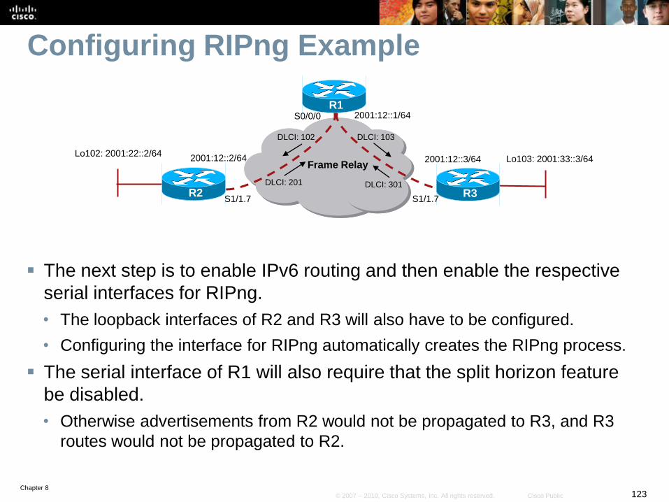
Configuring RIPng Example
The next step is to enable IPv6 routing and then enable the respective
serial interfaces for RIPng.
• The loopback interfaces of R2 and R3 will also have to be configured.
• Configuring the interface for RIPng automatically creates the RIPng process.
The serial interface of R1 will also require that the split horizon feature
be disabled.
• Otherwise advertisements from R2 would not be propagated to R3, and R3
routes would not be propagated to R2.
Frame Relay
2001:12::1/64
R2 R3
R1
2001:12::3/642001:12::2/64
DLCI: 103
DLCI: 301DLCI: 201
DLCI: 102
S0/0/0
S1/1.7 S1/1.7
Lo103: 2001:33::3/64Lo102: 2001:22::2/64
Chapter 8124© 2007 – 2010, Cisco Systems, Inc. All rights reserved. Cisco Public
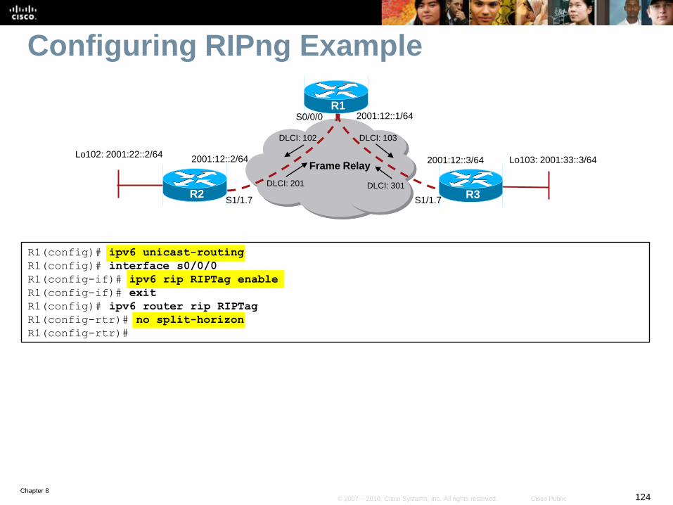
Configuring RIPng Example
R1(config)# ipv6 unicast-routing
R1(config)# interface s0/0/0
R1(config-if)# ipv6 rip RIPTag enable
R1(config-if)# exit
R1(config)# ipv6 router rip RIPTag
R1(config-rtr)# no split-horizon
R1(config-rtr)#
Frame Relay
2001:12::1/64
R2 R3
R1
2001:12::3/642001:12::2/64
DLCI: 103
DLCI: 301DLCI: 201
DLCI: 102
S0/0/0
S1/1.7 S1/1.7
Lo103: 2001:33::3/64Lo102: 2001:22::2/64
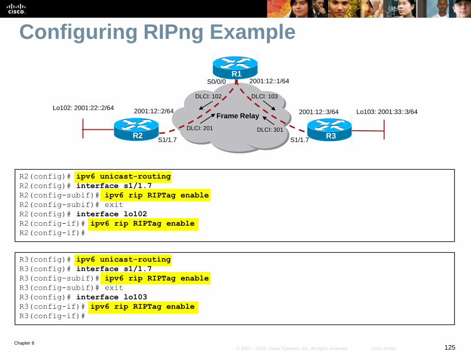
Chapter 8125© 2007 – 2010, Cisco Systems, Inc. All rights reserved. Cisco Public
Configuring RIPng Example
R2(config)# ipv6 unicast-routing
R2(config)# interface s1/1.7
R2(config-subif)# ipv6 rip RIPTag enable
R2(config-subif)# exit
R2(config)# interface lo102
R2(config-if)# ipv6 rip RIPTag enable
R2(config-if)#
Frame Relay
2001:12::1/64
R2 R3
R1
2001:12::3/642001:12::2/64
DLCI: 103
DLCI: 301DLCI: 201
DLCI: 102
S0/0/0
S1/1.7 S1/1.7
Lo103: 2001:33::3/64Lo102: 2001:22::2/64
R3(config)# ipv6 unicast-routing
R3(config)# interface s1/1.7
R3(config-subif)# ipv6 rip RIPTag enable
R3(config-subif)# exit
R3(config)# interface lo103
R3(config-if)# ipv6 rip RIPTag enable
R3(config-if)#
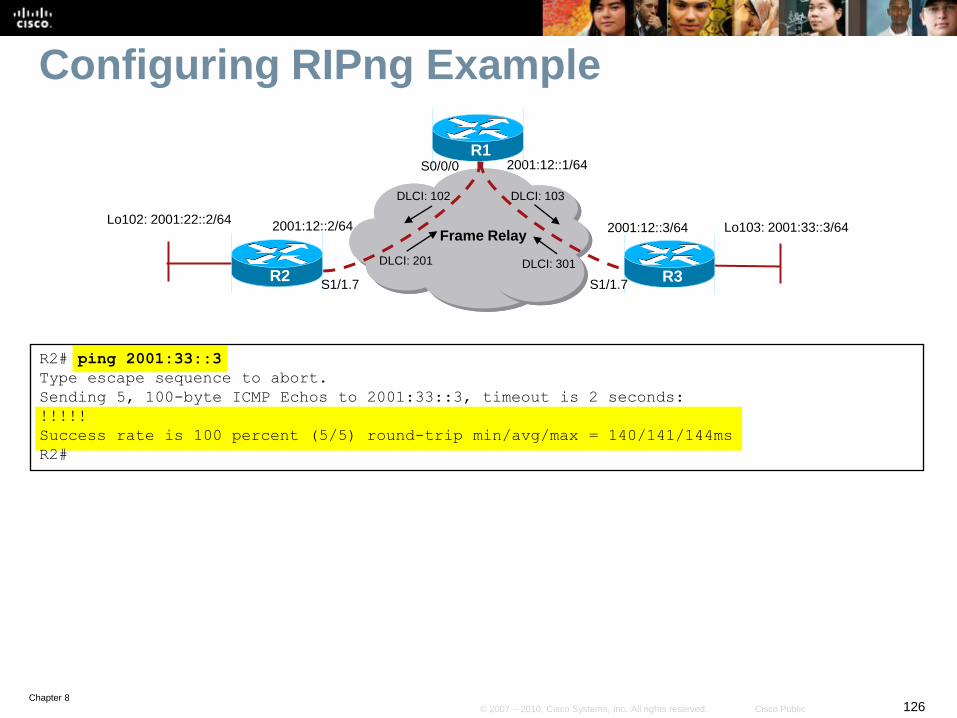
Chapter 8126© 2007 – 2010, Cisco Systems, Inc. All rights reserved. Cisco Public
Configuring RIPng Example
Frame Relay
2001:12::1/64
R2 R3
R1
2001:12::3/642001:12::2/64
DLCI: 103
DLCI: 301DLCI: 201
DLCI: 102
S0/0/0
S1/1.7 S1/1.7
Lo103: 2001:33::3/64Lo102: 2001:22::2/64
R2# ping 2001:33::3
Type escape sequence to abort.
Sending 5, 100-byte ICMP Echos to 2001:33::3, timeout is 2 seconds:
!!!!!
Success rate is 100 percent (5/5) round-trip min/avg/max = 140/141/144ms
R2#
Chapter 8127© 2007 – 2010, Cisco Systems, Inc. All rights reserved. Cisco Public
Configuring OSPFv3
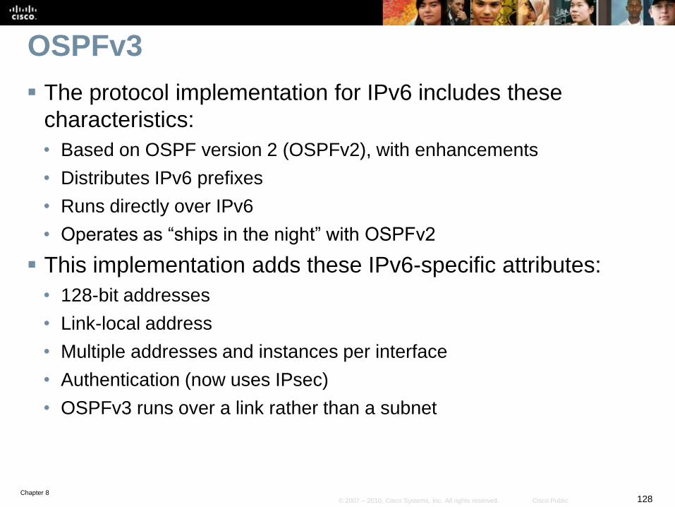
Chapter 8128© 2007 – 2010, Cisco Systems, Inc. All rights reserved. Cisco Public
OSPFv3
The protocol implementation for IPv6 includes these
characteristics:
• Based on OSPF version 2 (OSPFv2), with enhancements
• Distributes IPv6 prefixes
• Runs directly over IPv6
• Operates as “ships in the night” with OSPFv2
This implementation adds these IPv6-specific attributes:
• 128-bit addresses
• Link-local address
• Multiple addresses and instances per interface
• Authentication (now uses IPsec)
• OSPFv3 runs over a link rather than a subnet
Chapter 8129© 2007 – 2010, Cisco Systems, Inc. All rights reserved. Cisco Public
OSPFv3
Open Shortest Path First version 3 (OSPFv3 RFC 5340) is
a link state routing protocol for IPv6.
• It’s based on OSPFv2.
The following remained the same as OSPFv2:
• Packet types (Hello, DBD, LSR, LSU, LSA)
• Mechanisms for neighbor discovery and adjacency formation
• LSA flooding and aging (but there are now 3 types of scopes)
• SPF calculations
• DR election procedure
• Multi-area support (including NSSA)
• Multiple topologies support (NBMA, point-to-multipoint, point-to-point and
broadcast)
• Router-ID is still a 32-bit address
Chapter 8130© 2007 – 2010, Cisco Systems, Inc. All rights reserved. Cisco Public
OSPFv2 and OSPFv3 Differences
Unlike OSPFv2, OSPFv3:
• OSPFv3 runs over a link and is configured on an interface.
• Uses the term “link” similarly to IPv4 OSPF's “subnet” or “network”.
• IPv6 link-local addresses are required.
• There are now three separate LSA flooding scopes: Link-local scope,
Area scope, and AS scope.
• Multiple OSPFv3 instances are supported on one interface.
• Multicast addresses have changed.
• Security is improved.
Chapter 8131© 2007 – 2010, Cisco Systems, Inc. All rights reserved. Cisco Public
OSPFv3 Runs Over a Link
• OSPFv3 runs over a link as opposed to IPv4 over an IP
subnet.
• IPv6 uses the term “link” which replaces the terms “network” and
“subnet” used in the IPv4 OSPF.
• The network statement in the router subcommand mode
of OSPFv2 is replaced by the ipv6 ospf process-id
area area-id interface command.
Chapter 8132© 2007 – 2010, Cisco Systems, Inc. All rights reserved. Cisco Public
Link-Local Addresses Are Used
• OSPFv3 uses IPv6 link-local addresses to identify the
OSPFv3 adjacency neighbors.
• Therefore, when configuring the ipv6 ospf neighbor
command, the IPv6 address used must be the link-local
address of the neighbor.
Chapter 8133© 2007 – 2010, Cisco Systems, Inc. All rights reserved. Cisco Public
Multiple OSPFv3 Instance Support
Separate autonomous systems, each running OSPF, use a
common link.
• A single link could belong to multiple areas.
OSPFv3 uses a new field, called the Instance ID, to allow
multiple instances per link.
• To have two instances talk to each other, they must share the same
instance ID.
• By default, the instance ID is set to 0.
Chapter 8134© 2007 – 2010, Cisco Systems, Inc. All rights reserved. Cisco Public
Multicast Addresses
• FF02::5
• Represents all OSPFv3 routers on the link-local scope, equivalent to
224.0.0.5 in OSPFv2.
• FF02::6
• Represents all designated routers (DRs) on the link-local scope,
equivalent to 224.0.0.6 in OSPFv2.
Chapter 8135© 2007 – 2010, Cisco Systems, Inc. All rights reserved. Cisco Public
Removal of Address Semantics
IPv6 addresses are not present in the OSPF packet header
(part of payload information).
• Router LSAs and network LSAs do not carry IPv6 addresses.
• The router ID, area ID, and link-state ID remain at 32 bits.
• The DR and BDR are identified by their router ID and not by their IP
address.
Chapter 8136© 2007 – 2010, Cisco Systems, Inc. All rights reserved. Cisco Public
Security
OSPFv3 uses IPv6 IPsec AH and ESP extension headers
instead of the variety of mechanisms defined in OSPFv2.
Authentication is no longer part of OSPF.
• It is now the job of IPv6 and IPsec to make sure that the right level of
authentication is in use.
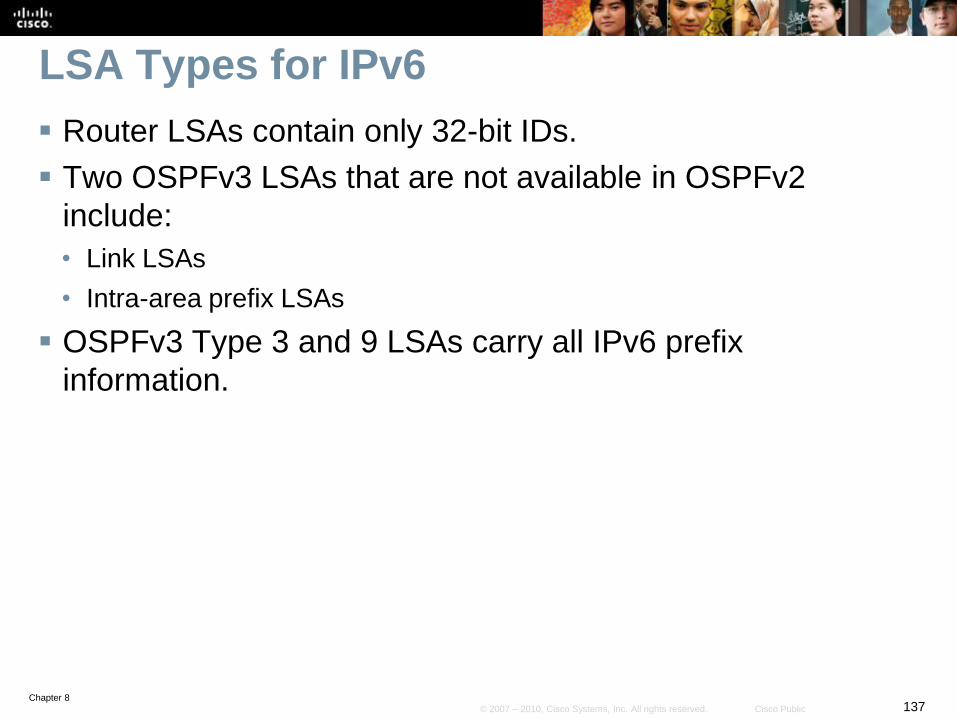
Chapter 8137© 2007 – 2010, Cisco Systems, Inc. All rights reserved. Cisco Public
LSA Types for IPv6
Router LSAs contain only 32-bit IDs.
Two OSPFv3 LSAs that are not available in OSPFv2
include:
• Link LSAs
• Intra-area prefix LSAs
OSPFv3 Type 3 and 9 LSAs carry all IPv6 prefix
information.
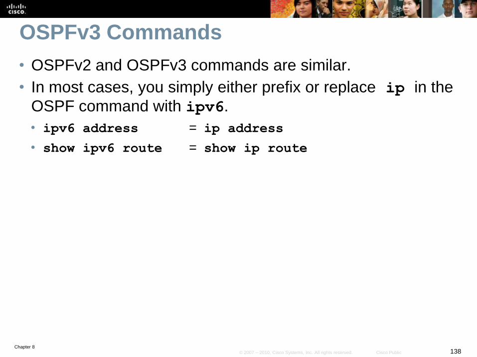
Chapter 8138© 2007 – 2010, Cisco Systems, Inc. All rights reserved. Cisco Public
OSPFv3 Commands
• OSPFv2 and OSPFv3 commands are similar.
• In most cases, you simply either prefix or replace ip in the
OSPF command with ipv6.
• ipv6 address = ip address
• show ipv6 route = show ip route
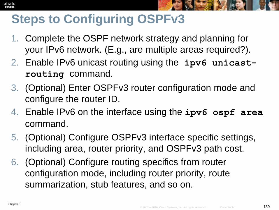
Chapter 8139© 2007 – 2010, Cisco Systems, Inc. All rights reserved. Cisco Public
Steps to Configuring OSPFv3
1. Complete the OSPF network strategy and planning for
your IPv6 network. (E.g., are multiple areas required?).
2. Enable IPv6 unicast routing using the ipv6 unicast-
routing command.
3. (Optional) Enter OSPFv3 router configuration mode and
configure the router ID.
4. Enable IPv6 on the interface using the ipv6 ospf area
command.
5. (Optional) Configure OSPFv3 interface specific settings,
including area, router priority, and OSPFv3 path cost.
6. (Optional) Configure routing specifics from router
configuration mode, including router priority, route
summarization, stub features, and so on.
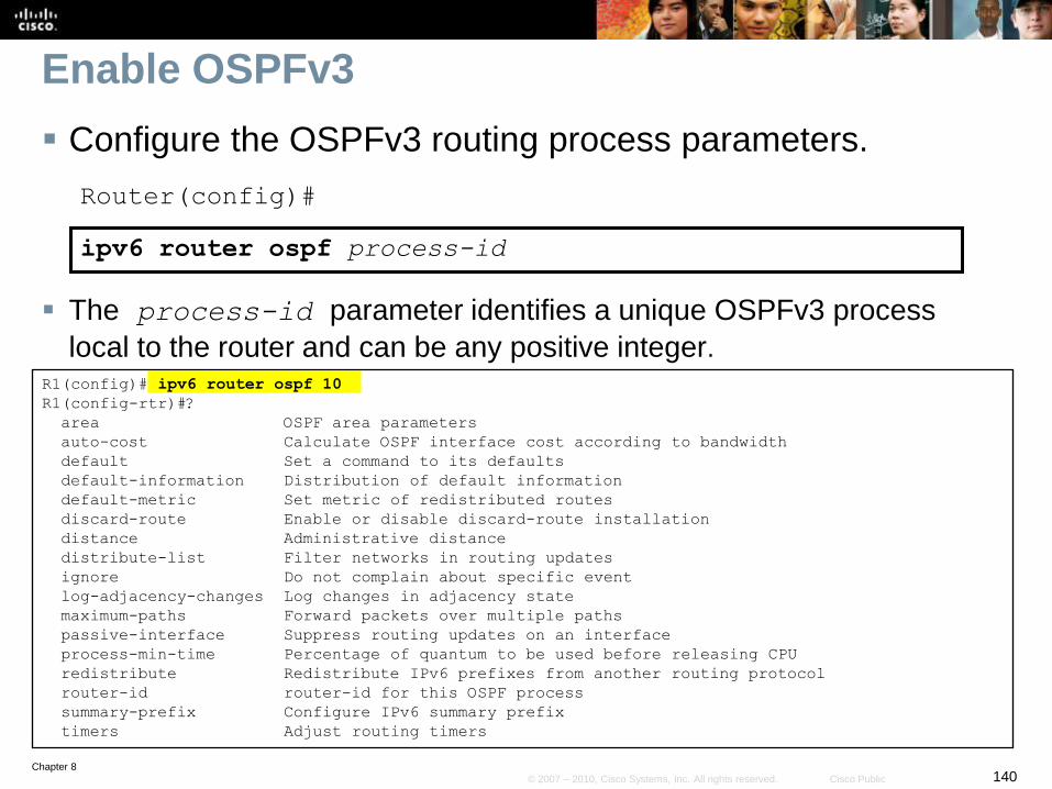
Chapter 8140© 2007 – 2010, Cisco Systems, Inc. All rights reserved. Cisco Public
Enable OSPFv3
Configure the OSPFv3 routing process parameters.
Router(config)#
ipv6 router ospf process-id
The process-id parameter identifies a unique OSPFv3 process
local to the router and can be any positive integer. R1(config)# ipv6 router ospf 10
R1(config-rtr)#?
area OSPF area parameters
auto-cost Calculate OSPF interface cost according to bandwidth
default Set a command to its defaults
default-information Distribution of default information
default-metric Set metric of redistributed routes
discard-route Enable or disable discard-route installation
distance Administrative distance
distribute-list Filter networks in routing updates
ignore Do not complain about specific event
log-adjacency-changes Log changes in adjacency state
maximum-paths Forward packets over multiple paths
passive-interface Suppress routing updates on an interface
process-min-time Percentage of quantum to be used before releasing CPU
redistribute Redistribute IPv6 prefixes from another routing protocol
router-id router-id for this OSPF process
summary-prefix Configure IPv6 summary prefix
timers Adjust routing timers
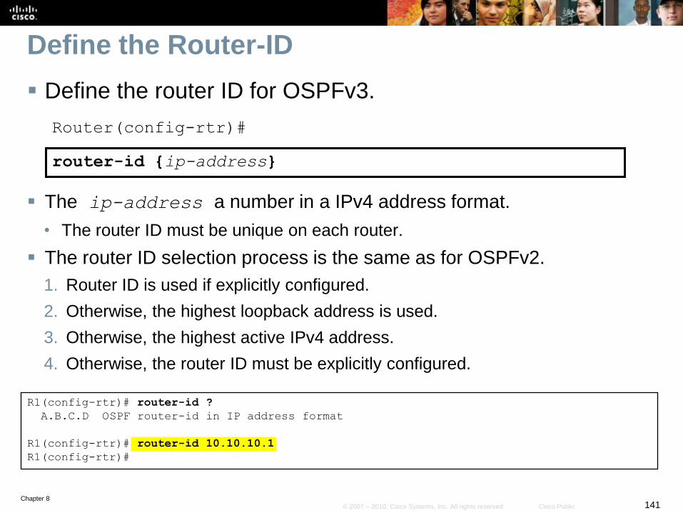
Chapter 8141© 2007 – 2010, Cisco Systems, Inc. All rights reserved. Cisco Public
Define the Router-ID
Define the router ID for OSPFv3.
Router(config-rtr)#
router-id {ip-address}
The ip-address a number in a IPv4 address format.
• The router ID must be unique on each router.
The router ID selection process is the same as for OSPFv2.
1. Router ID is used if explicitly configured.
2. Otherwise, the highest loopback address is used.
3. Otherwise, the highest active IPv4 address.
4. Otherwise, the router ID must be explicitly configured.
R1(config-rtr)# router-id ?
A.B.C.D OSPF router-id in IP address format
R1(config-rtr)# router-id 10.10.10.1
R1(config-rtr)#
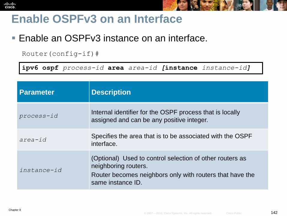
Chapter 8142© 2007 – 2010, Cisco Systems, Inc. All rights reserved. Cisco Public
Enable OSPFv3 on an Interface
Enable an OSPFv3 instance on an interface.
Router(config-if)#
ipv6 ospf process-id area area-id [instance instance-id]
Parameter Description
process-idInternal identifier for the OSPF process that is locally
assigned and can be any positive integer.
area-idSpecifies the area that is to be associated with the OSPF
interface.
instance-id
(Optional) Used to control selection of other routers as
neighboring routers.
Router becomes neighbors only with routers that have the
same instance ID.
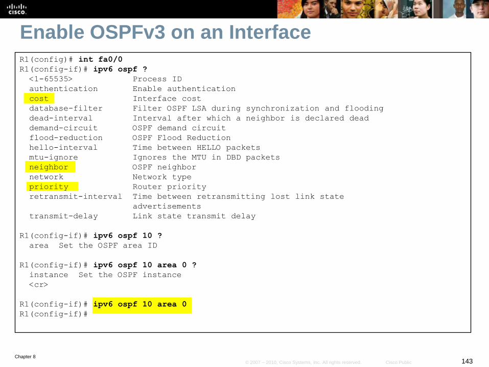
Chapter 8143© 2007 – 2010, Cisco Systems, Inc. All rights reserved. Cisco Public
Enable OSPFv3 on an InterfaceR1(config)# int fa0/0
R1(config-if)# ipv6 ospf ?
<1-65535> Process ID
authentication Enable authentication
cost Interface cost
database-filter Filter OSPF LSA during synchronization and flooding
dead-interval Interval after which a neighbor is declared dead
demand-circuit OSPF demand circuit
flood-reduction OSPF Flood Reduction
hello-interval Time between HELLO packets
mtu-ignore Ignores the MTU in DBD packets
neighbor OSPF neighbor
network Network type
priority Router priority
retransmit-interval Time between retransmitting lost link state
advertisements
transmit-delay Link state transmit delay
R1(config-if)# ipv6 ospf 10 ?
area Set the OSPF area ID
R1(config-if)# ipv6 ospf 10 area 0 ?
instance Set the OSPF instance
<cr>
R1(config-if)# ipv6 ospf 10 area 0
R1(config-if)#
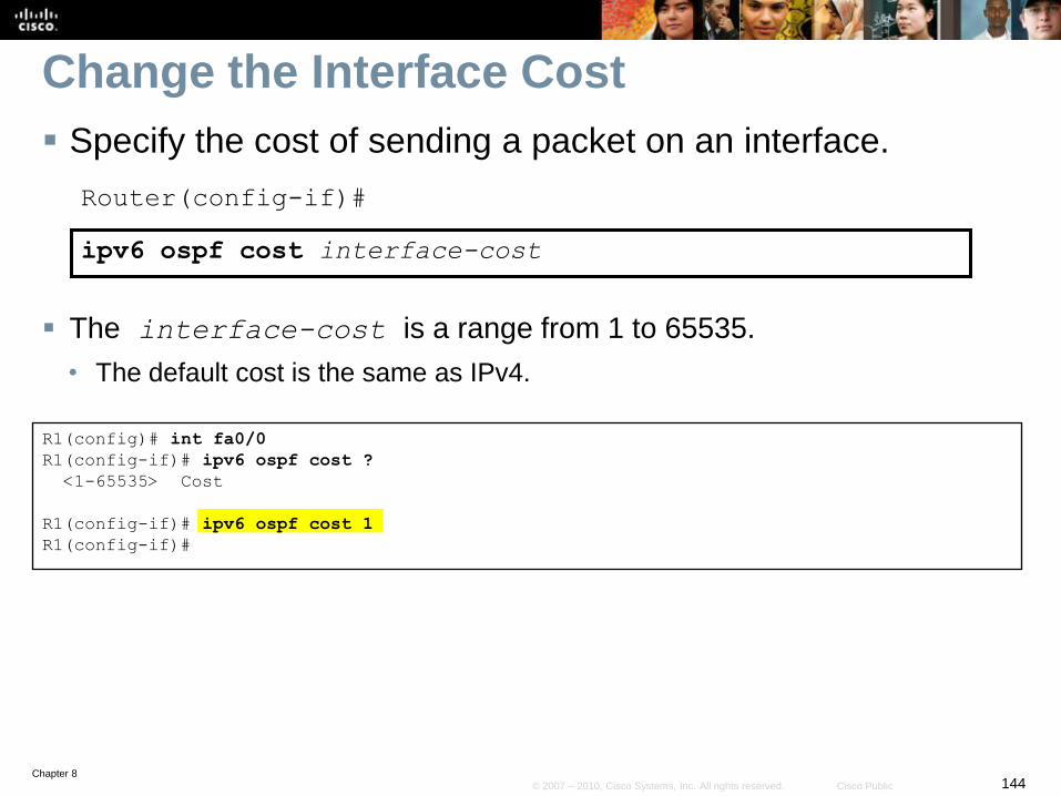
Chapter 8144© 2007 – 2010, Cisco Systems, Inc. All rights reserved. Cisco Public
Change the Interface Cost
Specify the cost of sending a packet on an interface.
Router(config-if)#
ipv6 ospf cost interface-cost
The interface-cost is a range from 1 to 65535.
• The default cost is the same as IPv4.
R1(config)# int fa0/0
R1(config-if)# ipv6 ospf cost ?
<1-65535> Cost
R1(config-if)# ipv6 ospf cost 1
R1(config-if)#
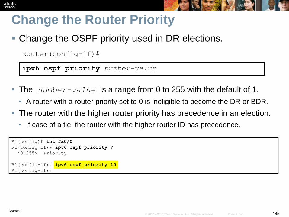
Chapter 8145© 2007 – 2010, Cisco Systems, Inc. All rights reserved. Cisco Public
Change the Router Priority
Change the OSPF priority used in DR elections.
Router(config-if)#
ipv6 ospf priority number-value
The number-value is a range from 0 to 255 with the default of 1.
• A router with a router priority set to 0 is ineligible to become the DR or BDR.
The router with the higher router priority has precedence in an election.
• If case of a tie, the router with the higher router ID has precedence.
R1(config)# int fa0/0
R1(config-if)# ipv6 ospf priority ?
<0-255> Priority
R1(config-if)# ipv6 ospf priority 10
R1(config-if)#
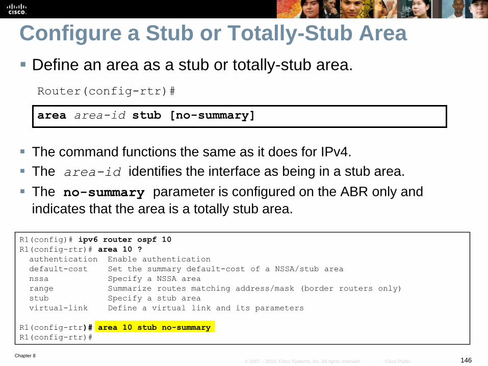
Chapter 8146© 2007 – 2010, Cisco Systems, Inc. All rights reserved. Cisco Public
Configure a Stub or Totally-Stub Area
Define an area as a stub or totally-stub area.
Router(config-rtr)#
area area-id stub [no-summary]
The command functions the same as it does for IPv4.
The area-id identifies the interface as being in a stub area.
The no-summary parameter is configured on the ABR only and
indicates that the area is a totally stub area.
R1(config)# ipv6 router ospf 10
R1(config-rtr)# area 10 ?
authentication Enable authentication
default-cost Set the summary default-cost of a NSSA/stub area
nssa Specify a NSSA area
range Summarize routes matching address/mask (border routers only)
stub Specify a stub area
virtual-link Define a virtual link and its parameters
R1(config-rtr)# area 10 stub no-summary
R1(config-rtr)#
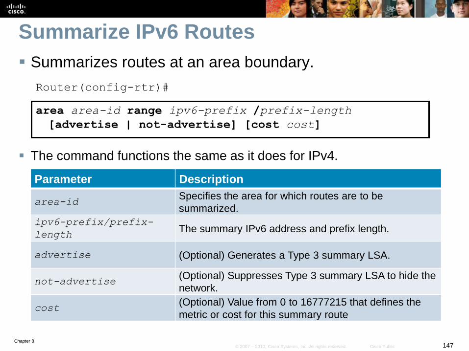
Chapter 8147© 2007 – 2010, Cisco Systems, Inc. All rights reserved. Cisco Public
Summarize IPv6 Routes
Summarizes routes at an area boundary.
Router(config-rtr)#
area area-id range ipv6-prefix /prefix-length
[advertise | not-advertise] [cost cost]
The command functions the same as it does for IPv4.
Parameter Description
area-idSpecifies the area for which routes are to be
summarized.
ipv6-prefix/prefix-
lengthThe summary IPv6 address and prefix length.
advertise (Optional) Generates a Type 3 summary LSA.
not-advertise(Optional) Suppresses Type 3 summary LSA to hide the
network.
cost(Optional) Value from 0 to 16777215 that defines the
metric or cost for this summary route
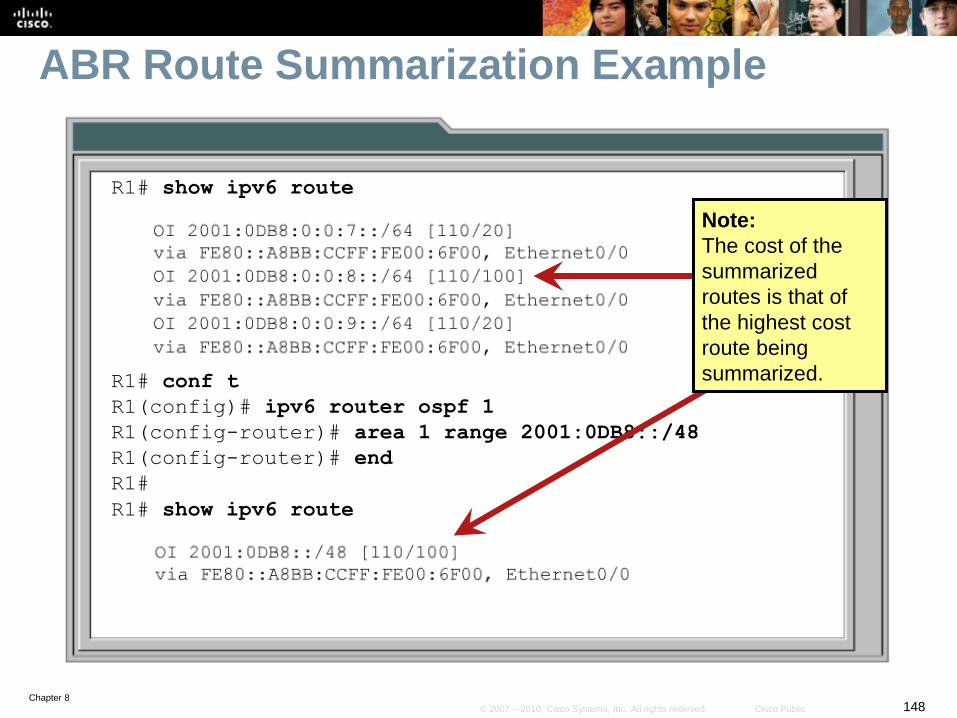
Chapter 8148© 2007 – 2010, Cisco Systems, Inc. All rights reserved. Cisco Public
ABR Route Summarization Example
R1# show ipv6 route
R1# conf t
R1(config)# ipv6 router ospf 1
R1(config-router)# area 1 range 2001:0DB8::/48
R1(config-router)# end
R1#
R1# show ipv6 route
Note:
The cost of the
summarized
routes is that of
the highest cost
route being
summarized.
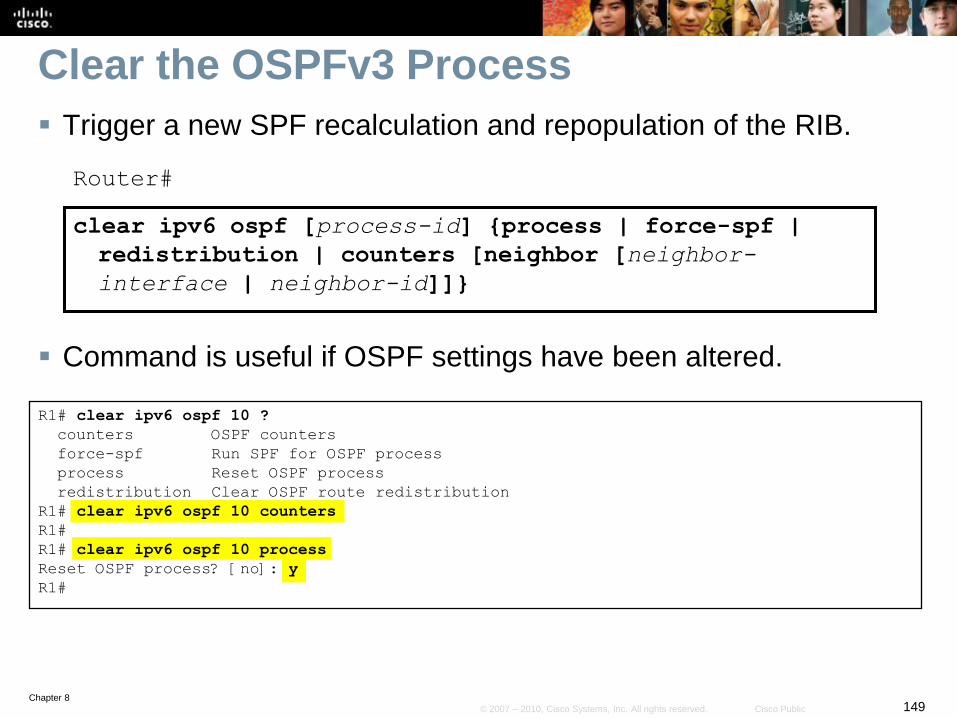
Chapter 8149© 2007 – 2010, Cisco Systems, Inc. All rights reserved. Cisco Public
Clear the OSPFv3 Process
Trigger a new SPF recalculation and repopulation of the RIB.
Router#
clear ipv6 ospf [process-id] {process | force-spf |
redistribution | counters [neighbor [neighbor-
interface | neighbor-id]]}
Command is useful if OSPF settings have been altered.
R1# clear ipv6 ospf 10 ?
counters OSPF counters
force-spf Run SPF for OSPF process
process Reset OSPF process
redistribution Clear OSPF route redistribution
R1# clear ipv6 ospf 10 counters
R1#
R1# clear ipv6 ospf 10 process
Reset OSPF process? [no]: y
R1#
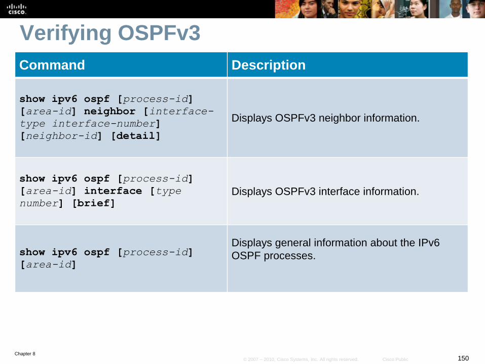
Chapter 8150© 2007 – 2010, Cisco Systems, Inc. All rights reserved. Cisco Public
Verifying OSPFv3
Command Description
show ipv6 ospf [process-id]
[area-id] neighbor [interface-
type interface-number]
[neighbor-id] [detail]
Displays OSPFv3 neighbor information.
show ipv6 ospf [process-id]
[area-id] interface [type
number] [brief] Displays OSPFv3 interface information.
show ipv6 ospf [process-id]
[area-id]
Displays general information about the IPv6
OSPF processes.
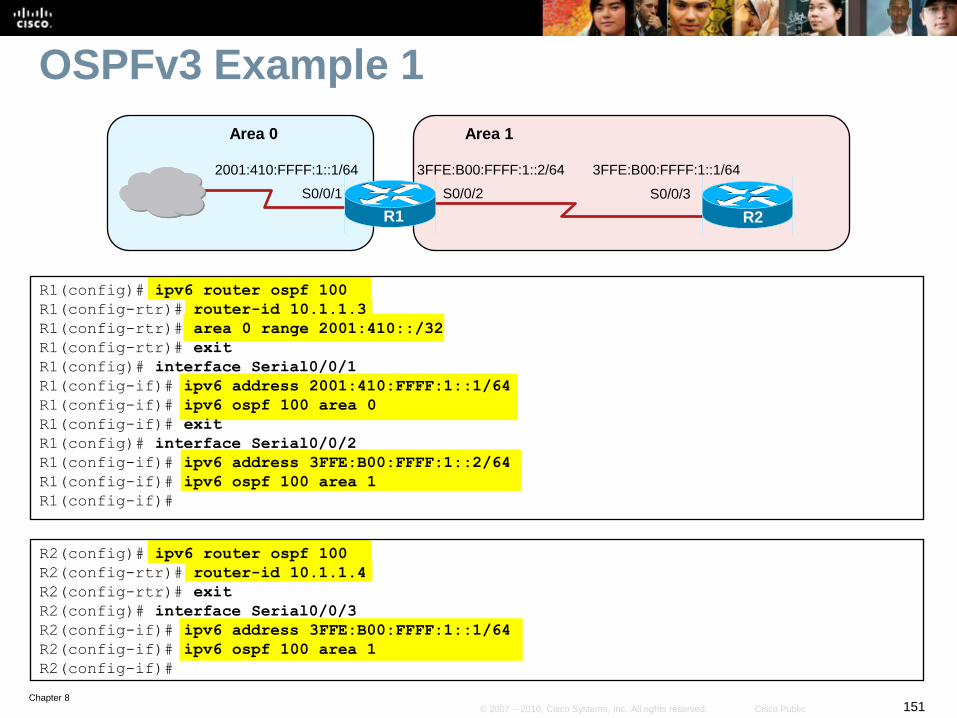
Chapter 8151© 2007 – 2010, Cisco Systems, Inc. All rights reserved. Cisco Public
OSPFv3 Example 1
S0/0/2 S0/0/3
R1
3FFE:B00:FFFF:1::1/64
R2
Area 0 Area 1
3FFE:B00:FFFF:1::2/64
S0/0/1
2001:410:FFFF:1::1/64
R1(config)# ipv6 router ospf 100
R1(config-rtr)# router-id 10.1.1.3
R1(config-rtr)# area 0 range 2001:410::/32
R1(config-rtr)# exit
R1(config)# interface Serial0/0/1
R1(config-if)# ipv6 address 2001:410:FFFF:1::1/64
R1(config-if)# ipv6 ospf 100 area 0
R1(config-if)# exit
R1(config)# interface Serial0/0/2
R1(config-if)# ipv6 address 3FFE:B00:FFFF:1::2/64
R1(config-if)# ipv6 ospf 100 area 1
R1(config-if)#
R2(config)# ipv6 router ospf 100
R2(config-rtr)# router-id 10.1.1.4
R2(config-rtr)# exit
R2(config)# interface Serial0/0/3
R2(config-if)# ipv6 address 3FFE:B00:FFFF:1::1/64
R2(config-if)# ipv6 ospf 100 area 1
R2(config-if)#
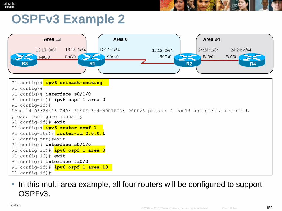
Chapter 8152© 2007 – 2010, Cisco Systems, Inc. All rights reserved. Cisco Public
OSPFv3 Example 2
In this multi-area example, all four routers will be configured to support
OSPFv3.
R1(config)# ipv6 unicast-routing
R1(config)#
R1(config)# interface s0/1/0
R1(config-if)# ipv6 ospf 1 area 0
R1(config-if)#
*Aug 14 06:24:23.040: %OSPFv3-4-NORTRID: OSPFv3 process 1 could not pick a routerid,
please configure manually
R1(config-if)# exit
R1(config)# ipv6 router ospf 1
R1(config-rtr)# router-id 0.0.0.1
R1(config-rtr)#exit
R1(config)# interface s0/1/0
R1(config-if)# ipv6 ospf 1 area 0
R1(config-if)# exit
R1(config)# interface fa0/0
R1(config-if)# ipv6 ospf 1 area 13
R1(config-if)#
S0/1/0 S0/1/0
R1
12:12::2/64
R2
Area 13 Area 0
12:12::1/64
Fa0/0
13:13::1/64
R3
Fa0/0
13:13::3/64
Area 24
24:24::4/64
R4
Fa0/0
24:24::1/64
Fa0/0
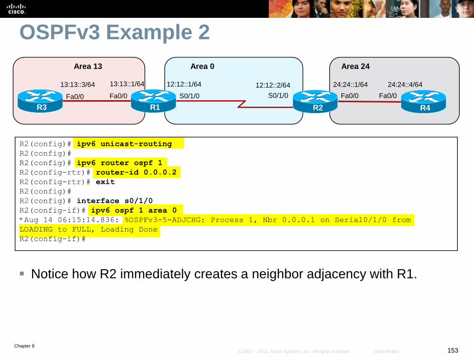
Chapter 8153© 2007 – 2010, Cisco Systems, Inc. All rights reserved. Cisco Public
OSPFv3 Example 2
Notice how R2 immediately creates a neighbor adjacency with R1.
R2(config)# ipv6 unicast-routing
R2(config)#
R2(config)# ipv6 router ospf 1
R2(config-rtr)# router-id 0.0.0.2
R2(config-rtr)# exit
R2(config)#
R2(config)# interface s0/1/0
R2(config-if)# ipv6 ospf 1 area 0
*Aug 14 06:15:14.836: %OSPFv3-5-ADJCHG: Process 1, Nbr 0.0.0.1 on Serial0/1/0 from
LOADING to FULL, Loading Done
R2(config-if)#
S0/1/0 S0/1/0
R1
12:12::2/64
R2
Area 13 Area 0
12:12::1/64
Fa0/0
13:13::1/64
R3
Fa0/0
13:13::3/64
Area 24
24:24::4/64
R4
Fa0/0
24:24::1/64
Fa0/0
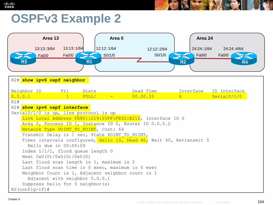
Chapter 8154© 2007 – 2010, Cisco Systems, Inc. All rights reserved. Cisco Public
OSPFv3 Example 2
R2# show ipv6 ospf neighbor
Neighbor ID Pri State Dead Time Interface ID Interface
0.0.0.1 1 FULL/ - 00.00.33 6 Serial0/1/0
R2#
R2# show ipv6 ospf interface
Serial0/1/0 is up, line protocol is up
Link Local Address FE80::219:55FF:FE92:B212, Interface ID 6
Area 0, Process ID 1, Instance ID 0, Router ID 0.0.0.2
Network Type POINT_TO_POINT, Cost: 64
Transmit Delay is 1 sec, State POINT_TO_POINT,
Timer intervals configured, Hello 10, Dead 40, Wait 40, Retransmit 5
Hello due in 00:00:09
Index 1/1/1, flood queue length 0
Next 0x0(0)/0x0(0)/0x0(0)
Last flood scan length is 1, maximum is 2
Last flood scan time is 0 msec, maximum is 0 msec
Neighbor Count is 1, Adjacent neighbor count is 1
Adjacent with neighbor 0.0.0.1
Suppress hello for 0 neighbor(s)
R2(config-if)#
S0/1/0 S0/1/0
R1
12:12::2/64
R2
Area 13 Area 0
12:12::1/64
Fa0/0
13:13::1/64
R3
Fa0/0
13:13::3/64
Area 24
24:24::4/64
R4
Fa0/0
24:24::1/64
Fa0/0
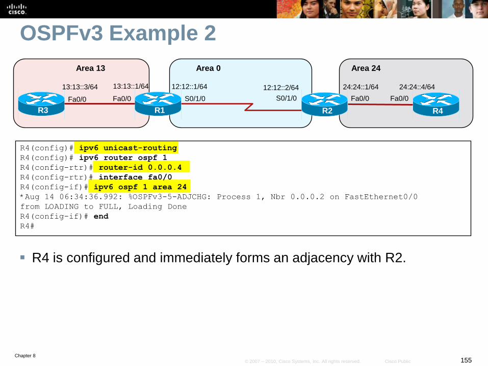
Chapter 8155© 2007 – 2010, Cisco Systems, Inc. All rights reserved. Cisco Public
OSPFv3 Example 2
R4 is configured and immediately forms an adjacency with R2.
R4(config)# ipv6 unicast-routing
R4(config)# ipv6 router ospf 1
R4(config-rtr)# router-id 0.0.0.4
R4(config-rtr)# interface fa0/0
R4(config-if)# ipv6 ospf 1 area 24
*Aug 14 06:34:36.992: %OSPFv3-5-ADJCHG: Process 1, Nbr 0.0.0.2 on FastEthernet0/0
from LOADING to FULL, Loading Done
R4(config-if)# end
R4#
S0/1/0 S0/1/0
R1
12:12::2/64
R2
Area 13 Area 0
12:12::1/64
Fa0/0
13:13::1/64
R3
Fa0/0
13:13::3/64
Area 24
24:24::4/64
R4
Fa0/0
24:24::1/64
Fa0/0
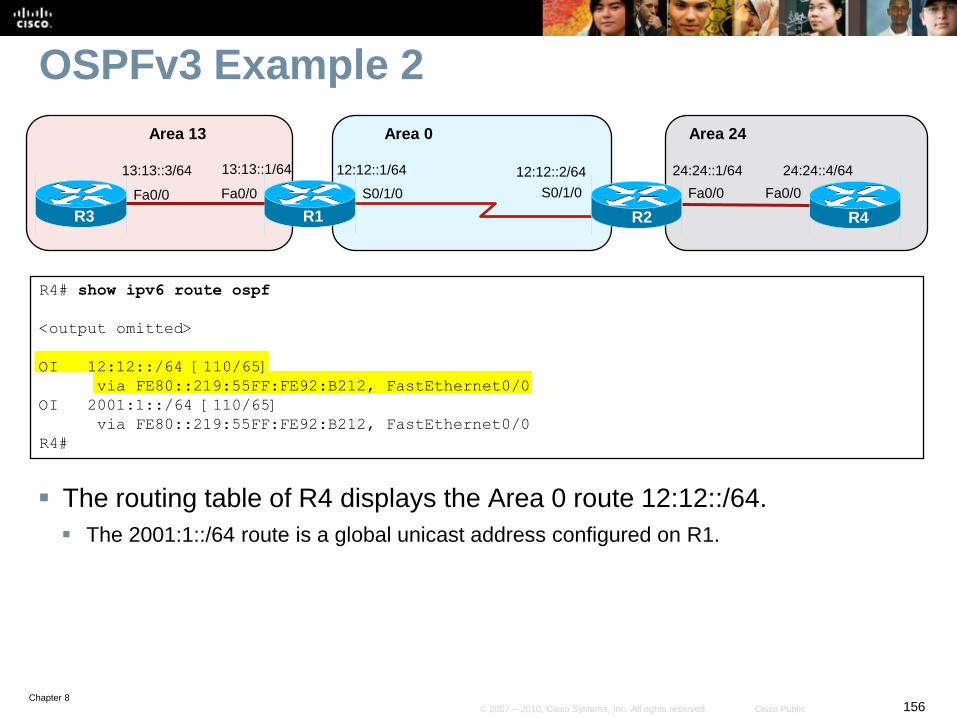
Chapter 8156© 2007 – 2010, Cisco Systems, Inc. All rights reserved. Cisco Public
OSPFv3 Example 2
The routing table of R4 displays the Area 0 route 12:12::/64.
The 2001:1::/64 route is a global unicast address configured on R1.
R4# show ipv6 route ospf
<output omitted>
OI 12:12::/64 [110/65]
via FE80::219:55FF:FE92:B212, FastEthernet0/0
OI 2001:1::/64 [110/65]
via FE80::219:55FF:FE92:B212, FastEthernet0/0
R4#
S0/1/0 S0/1/0
R1
12:12::2/64
R2
Area 13 Area 0
12:12::1/64
Fa0/0
13:13::1/64
R3
Fa0/0
13:13::3/64
Area 24
24:24::4/64
R4
Fa0/0
24:24::1/64
Fa0/0
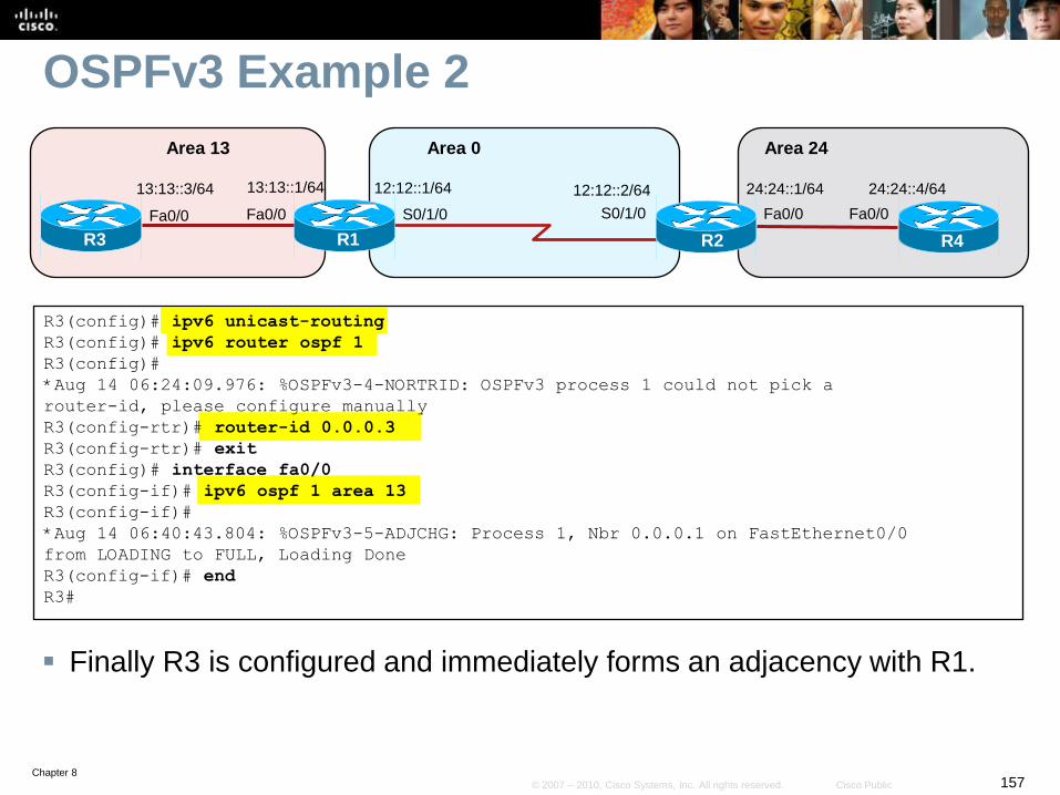
Chapter 8157© 2007 – 2010, Cisco Systems, Inc. All rights reserved. Cisco Public
OSPFv3 Example 2
Finally R3 is configured and immediately forms an adjacency with R1.
R3(config)# ipv6 unicast-routing
R3(config)# ipv6 router ospf 1
R3(config)#
*Aug 14 06:24:09.976: %OSPFv3-4-NORTRID: OSPFv3 process 1 could not pick a
router-id, please configure manually
R3(config-rtr)# router-id 0.0.0.3
R3(config-rtr)# exit
R3(config)# interface fa0/0
R3(config-if)# ipv6 ospf 1 area 13
R3(config-if)#
*Aug 14 06:40:43.804: %OSPFv3-5-ADJCHG: Process 1, Nbr 0.0.0.1 on FastEthernet0/0
from LOADING to FULL, Loading Done
R3(config-if)# end
R3#
S0/1/0 S0/1/0
R1
12:12::2/64
R2
Area 13 Area 0
12:12::1/64
Fa0/0
13:13::1/64
R3
Fa0/0
13:13::3/64
Area 24
24:24::4/64
R4
Fa0/0
24:24::1/64
Fa0/0
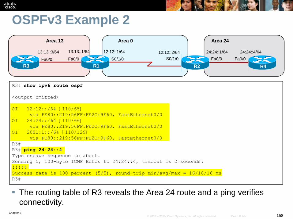
Chapter 8158© 2007 – 2010, Cisco Systems, Inc. All rights reserved. Cisco Public
OSPFv3 Example 2
The routing table of R3 reveals the Area 24 route and a ping verifies
connectivity.
R3# show ipv6 route ospf
<output omitted>
OI 12:12::/64 [110/65]
via FE80::219:56FF:FE2C:9F60, FastEthernet0/0
OI 24:24::/64 [110/66]
via FE80::219:56FF:FE2C:9F60, FastEthernet0/0
OI 2001:1::/64 [110/129]
via FE80::219:56FF:FE2C:9F60, FastEthernet0/0
R3#
R3# ping 24:24::4
Type escape sequence to abort.
Sending 5, 100-byte ICMP Echos to 24:24::4, timeout is 2 seconds:
!!!!!
Success rate is 100 percent (5/5), round-trip min/avg/max = 16/16/16 ms
R3#
S0/1/0 S0/1/0
R1
12:12::2/64
R2
Area 13 Area 0
12:12::1/64
Fa0/0
13:13::1/64
R3
Fa0/0
13:13::3/64
Area 24
24:24::4/64
R4
Fa0/0
24:24::1/64
Fa0/0
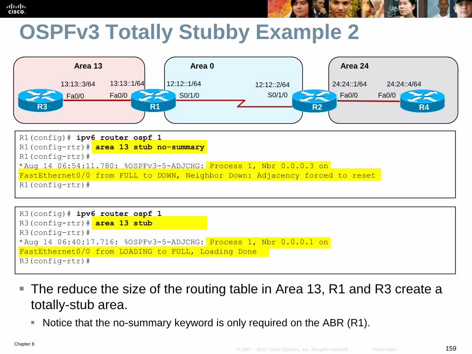
Chapter 8159© 2007 – 2010, Cisco Systems, Inc. All rights reserved. Cisco Public
OSPFv3 Totally Stubby Example 2
The reduce the size of the routing table in Area 13, R1 and R3 create a
totally-stub area.
Notice that the no-summary keyword is only required on the ABR (R1).
R1(config)# ipv6 router ospf 1
R1(config-rtr)# area 13 stub no-summary
R1(config-rtr)#
*Aug 14 06:54:11.780: %OSPFv3-5-ADJCHG: Process 1, Nbr 0.0.0.3 on
FastEthernet0/0 from FULL to DOWN, Neighbor Down: Adjacency forced to reset
R1(config-rtr)#
S0/1/0 S0/1/0
R1
12:12::2/64
R2
Area 13 Area 0
12:12::1/64
Fa0/0
13:13::1/64
R3
Fa0/0
13:13::3/64
Area 24
24:24::4/64
R4
Fa0/0
24:24::1/64
Fa0/0
R3(config)# ipv6 router ospf 1
R3(config-rtr)# area 13 stub
R3(config-rtr)#
*Aug 14 06:40:17.716: %OSPFv3-5-ADJCHG: Process 1, Nbr 0.0.0.1 on
FastEthernet0/0 from LOADING to FULL, Loading Done
R3(config-rtr)#
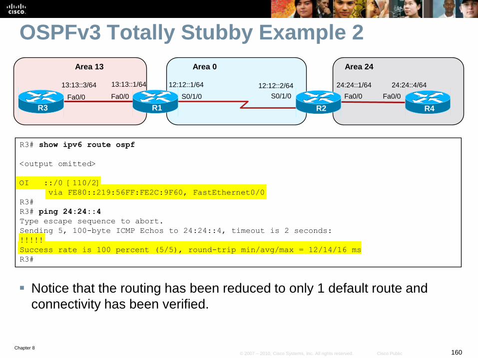
Chapter 8160© 2007 – 2010, Cisco Systems, Inc. All rights reserved. Cisco Public
OSPFv3 Totally Stubby Example 2
Notice that the routing has been reduced to only 1 default route and
connectivity has been verified.
R3# show ipv6 route ospf
<output omitted>
OI ::/0 [110/2]
via FE80::219:56FF:FE2C:9F60, FastEthernet0/0
R3#
R3# ping 24:24::4
Type escape sequence to abort.
Sending 5, 100-byte ICMP Echos to 24:24::4, timeout is 2 seconds:
!!!!!
Success rate is 100 percent (5/5), round-trip min/avg/max = 12/14/16 ms
R3#
S0/1/0 S0/1/0
R1
12:12::2/64
R2
Area 13 Area 0
12:12::1/64
Fa0/0
13:13::1/64
R3
Fa0/0
13:13::3/64
Area 24
24:24::4/64
R4
Fa0/0
24:24::1/64
Fa0/0

Chapter 8161© 2007 – 2010, Cisco Systems, Inc. All rights reserved. Cisco Public
Configuring EIGRP for IPv6
Chapter 8162© 2007 – 2010, Cisco Systems, Inc. All rights reserved. Cisco Public
EIGRP for IPv6
EIGRP for IPv6 is a distance-vector routing protocol.
• The configuration and operation is similar to EIGRP for IPv4.
The following remained the same as EIGRP for IPv4:
• Uses the same protocol number (88)
• Maintains a topology table and uses queries if no feasible successors are
available.
• Uses DUAL to calculate the successor routes
Unlike EIGRP for IPv4, EIGRP for IPv6:
• Is used to route IPv6 prefixes.
• Requires that a 32-bit router ID be assigned.
• It is configured on an interface.
• Link-local addressing is used for establishing neighbor adjacencies.
• It starts in shutdown state
• It does not automatically summarize.
Chapter 8163© 2007 – 2010, Cisco Systems, Inc. All rights reserved. Cisco Public
Steps to Configuring EIGRP for IPv6
1. Complete the EIGRP network strategy and planning for your IPv6
network.
2. Enable IPv6 unicast routing using the ipv6 unicast-routing
command.
3. (Optional) Enter EIGRP router configuration mode and configure the
router ID.
4. Enable EIGRP for IPv6 on the interface using the ipv6 eigrp
command.
5. (Optional) Configure EIGRP for IPv6 interface specific settings.
6. (Optional) Configure routing specifics from router configuration mode.
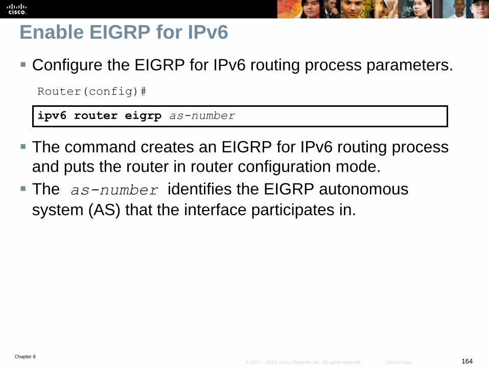
Chapter 8164© 2007 – 2010, Cisco Systems, Inc. All rights reserved. Cisco Public
Enable EIGRP for IPv6
Configure the EIGRP for IPv6 routing process parameters.
Router(config)#
ipv6 router eigrp as-number
The command creates an EIGRP for IPv6 routing process
and puts the router in router configuration mode.
The as-number identifies the EIGRP autonomous
system (AS) that the interface participates in.
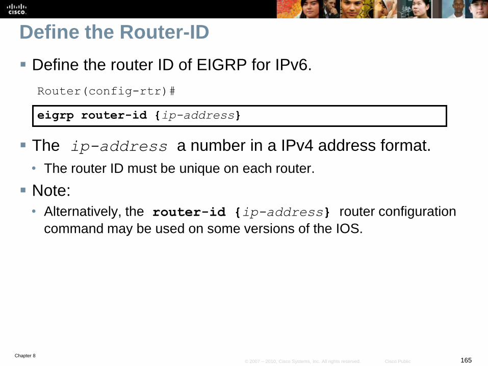
Chapter 8165© 2007 – 2010, Cisco Systems, Inc. All rights reserved. Cisco Public
Define the Router-ID
Define the router ID of EIGRP for IPv6.
Router(config-rtr)#
eigrp router-id {ip-address}
The ip-address a number in a IPv4 address format.
• The router ID must be unique on each router.
Note:
• Alternatively, the router-id {ip-address} router configuration
command may be used on some versions of the IOS.
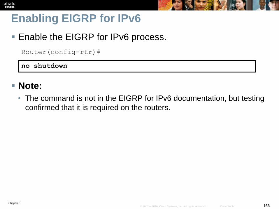
Chapter 8166© 2007 – 2010, Cisco Systems, Inc. All rights reserved. Cisco Public
Enabling EIGRP for IPv6
Enable the EIGRP for IPv6 process.
Router(config-rtr)#
no shutdown
Note:
• The command is not in the EIGRP for IPv6 documentation, but testing
confirmed that it is required on the routers.
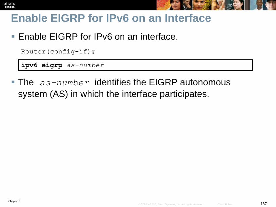
Chapter 8167© 2007 – 2010, Cisco Systems, Inc. All rights reserved. Cisco Public
Enable EIGRP for IPv6 on an Interface
Enable EIGRP for IPv6 on an interface.
Router(config-if)#
ipv6 eigrp as-number
The as-number identifies the EIGRP autonomous
system (AS) in which the interface participates.
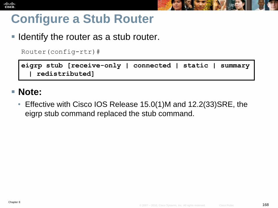
Chapter 8168© 2007 – 2010, Cisco Systems, Inc. All rights reserved. Cisco Public
Configure a Stub Router
Identify the router as a stub router.
Router(config-rtr)#
eigrp stub [receive-only | connected | static | summary
| redistributed]
Note:
• Effective with Cisco IOS Release 15.0(1)M and 12.2(33)SRE, the
eigrp stub command replaced the stub command.
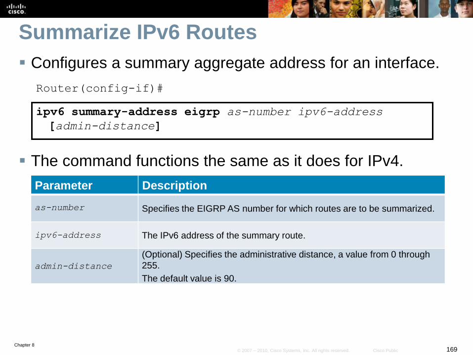
Chapter 8169© 2007 – 2010, Cisco Systems, Inc. All rights reserved. Cisco Public
Summarize IPv6 Routes
Configures a summary aggregate address for an interface.
Router(config-if)#
ipv6 summary-address eigrp as-number ipv6-address
[admin-distance]
The command functions the same as it does for IPv4.
Parameter Description
as-number Specifies the EIGRP AS number for which routes are to be summarized.
ipv6-address The IPv6 address of the summary route.
admin-distance
(Optional) Specifies the administrative distance, a value from 0 through
255.
The default value is 90.
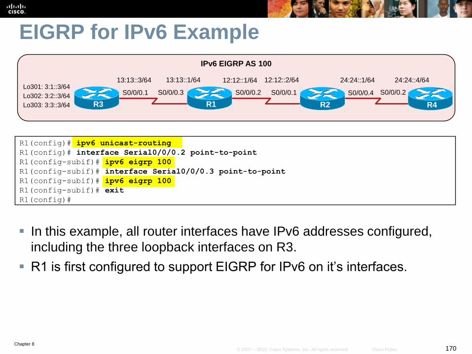
Chapter 8170© 2007 – 2010, Cisco Systems, Inc. All rights reserved. Cisco Public
EIGRP for IPv6 Example
In this example, all router interfaces have IPv6 addresses configured,
including the three loopback interfaces on R3.
R1 is first configured to support EIGRP for IPv6 on it’s interfaces.
R1(config)# ipv6 unicast-routing
R1(config)# interface Serial0/0/0.2 point-to-point
R1(config-subif)# ipv6 eigrp 100
R1(config-subif)# interface Serial0/0/0.3 point-to-point
R1(config-subif)# ipv6 eigrp 100
R1(config-subif)# exit
R1(config)#
S0/0/0.2 S0/0/0.1
R1
12:12::2/64
R2
IPv6 EIGRP AS 100
12:12::1/64
S0/0/0.3
13:13::1/64
R3
S0/0/0.1
13:13::3/64 24:24::4/64
R4
S0/0/0.2
24:24::1/64
S0/0/0.4Lo301: 3:1::3/64
Lo302: 3:2::3/64
Lo303: 3:3::3/64
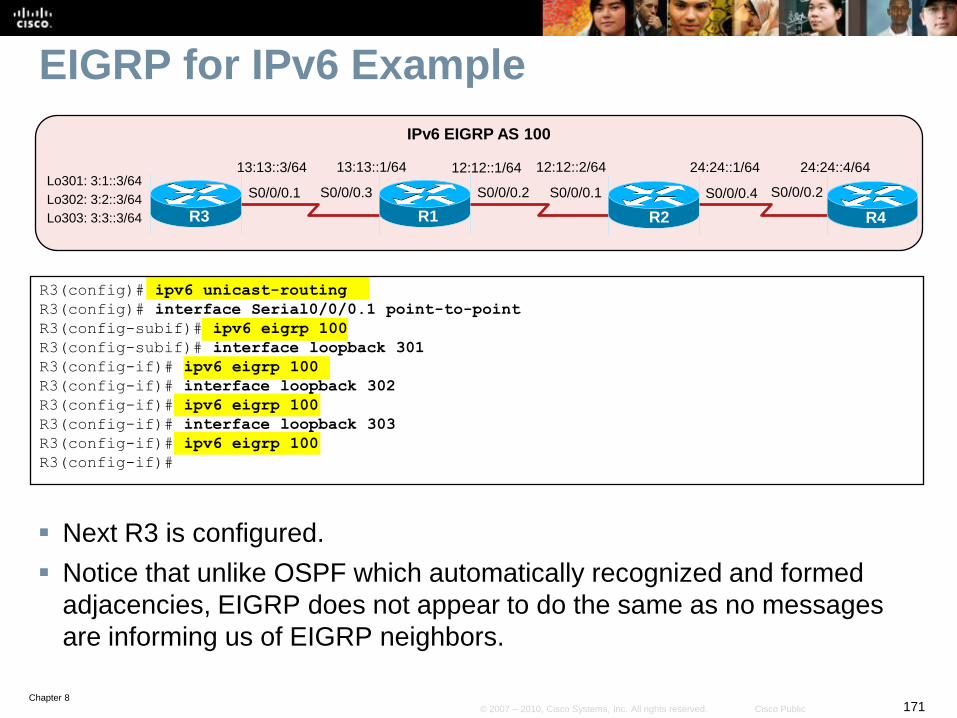
Chapter 8171© 2007 – 2010, Cisco Systems, Inc. All rights reserved. Cisco Public
EIGRP for IPv6 Example
Next R3 is configured.
Notice that unlike OSPF which automatically recognized and formed
adjacencies, EIGRP does not appear to do the same as no messages
are informing us of EIGRP neighbors.
R3(config)# ipv6 unicast-routing
R3(config)# interface Serial0/0/0.1 point-to-point
R3(config-subif)# ipv6 eigrp 100
R3(config-subif)# interface loopback 301
R3(config-if)# ipv6 eigrp 100
R3(config-if)# interface loopback 302
R3(config-if)# ipv6 eigrp 100
R3(config-if)# interface loopback 303
R3(config-if)# ipv6 eigrp 100
R3(config-if)#
S0/0/0.2 S0/0/0.1
R1
12:12::2/64
R2
IPv6 EIGRP AS 100
12:12::1/64
S0/0/0.3
13:13::1/64
R3
S0/0/0.1
13:13::3/64 24:24::4/64
R4
S0/0/0.2
24:24::1/64
S0/0/0.4Lo301: 3:1::3/64
Lo302: 3:2::3/64
Lo303: 3:3::3/64
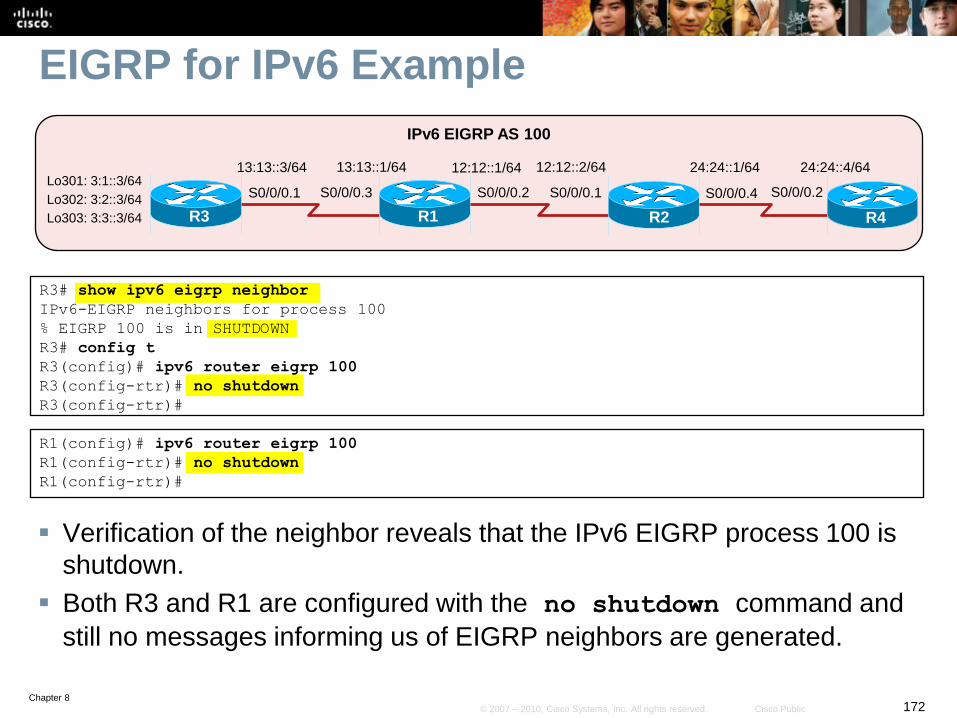
Chapter 8172© 2007 – 2010, Cisco Systems, Inc. All rights reserved. Cisco Public
EIGRP for IPv6 Example
Verification of the neighbor reveals that the IPv6 EIGRP process 100 is
shutdown.
Both R3 and R1 are configured with the no shutdown command and
still no messages informing us of EIGRP neighbors are generated.
R3# show ipv6 eigrp neighbor
IPv6-EIGRP neighbors for process 100
% EIGRP 100 is in SHUTDOWN
R3# config t
R3(config)# ipv6 router eigrp 100
R3(config-rtr)# no shutdown
R3(config-rtr)#
S0/0/0.2 S0/0/0.1
R1
12:12::2/64
R2
IPv6 EIGRP AS 100
12:12::1/64
S0/0/0.3
13:13::1/64
R3
S0/0/0.1
13:13::3/64 24:24::4/64
R4
S0/0/0.2
24:24::1/64
S0/0/0.4Lo301: 3:1::3/64
Lo302: 3:2::3/64
Lo303: 3:3::3/64
R1(config)# ipv6 router eigrp 100
R1(config-rtr)# no shutdown
R1(config-rtr)#
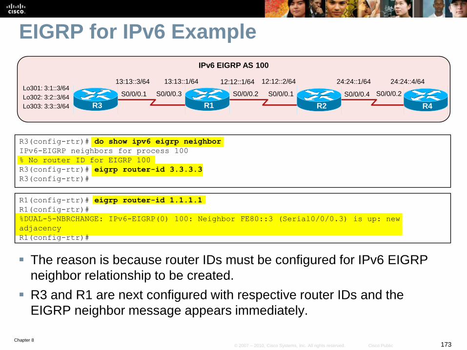
Chapter 8173© 2007 – 2010, Cisco Systems, Inc. All rights reserved. Cisco Public
EIGRP for IPv6 Example
The reason is because router IDs must be configured for IPv6 EIGRP
neighbor relationship to be created.
R3 and R1 are next configured with respective router IDs and the
EIGRP neighbor message appears immediately.
R3(config-rtr)# do show ipv6 eigrp neighbor
IPv6-EIGRP neighbors for process 100
% No router ID for EIGRP 100
R3(config-rtr)# eigrp router-id 3.3.3.3
R3(config-rtr)#
S0/0/0.2 S0/0/0.1
R1
12:12::2/64
R2
IPv6 EIGRP AS 100
12:12::1/64
S0/0/0.3
13:13::1/64
R3
S0/0/0.1
13:13::3/64 24:24::4/64
R4
S0/0/0.2
24:24::1/64
S0/0/0.4Lo301: 3:1::3/64
Lo302: 3:2::3/64
Lo303: 3:3::3/64
R1(config-rtr)# eigrp router-id 1.1.1.1
R1(config-rtr)#
%DUAL-5-NBRCHANGE: IPv6-EIGRP(0) 100: Neighbor FE80::3 (Serial0/0/0.3) is up: new
adjacency
R1(config-rtr)#
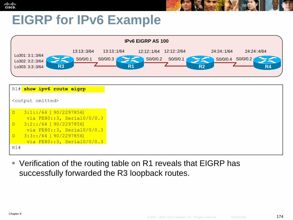
Chapter 8174© 2007 – 2010, Cisco Systems, Inc. All rights reserved. Cisco Public
EIGRP for IPv6 Example
Verification of the routing table on R1 reveals that EIGRP has
successfully forwarded the R3 loopback routes.
R1# show ipv6 route eigrp
<output omitted>
D 3:1::/64 [90/2297856]
via FE80::3, Serial0/0/0.3
D 3:2::/64 [90/2297856]
via FE80::3, Serial0/0/0.3
D 3:3::/64 [90/2297856]
via FE80::3, Serial0/0/0.3
R1#
S0/0/0.2 S0/0/0.1
R1
12:12::2/64
R2
IPv6 EIGRP AS 100
12:12::1/64
S0/0/0.3
13:13::1/64
R3
S0/0/0.1
13:13::3/64 24:24::4/64
R4
S0/0/0.2
24:24::1/64
S0/0/0.4Lo301: 3:1::3/64
Lo302: 3:2::3/64
Lo303: 3:3::3/64
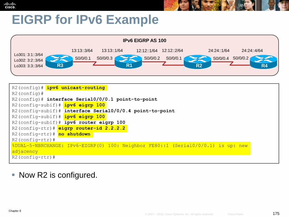
Chapter 8175© 2007 – 2010, Cisco Systems, Inc. All rights reserved. Cisco Public
EIGRP for IPv6 Example
Now R2 is configured.
S0/0/0.2 S0/0/0.1
R1
12:12::2/64
R2
IPv6 EIGRP AS 100
12:12::1/64
S0/0/0.3
13:13::1/64
R3
S0/0/0.1
13:13::3/64 24:24::4/64
R4
S0/0/0.2
24:24::1/64
S0/0/0.4Lo301: 3:1::3/64
Lo302: 3:2::3/64
Lo303: 3:3::3/64
R2(config)# ipv6 unicast-routing
R2(config)#
R2(config)# interface Serial0/0/0.1 point-to-point
R2(config-subif)# ipv6 eigrp 100
R2(config-subif)# interface Serial0/0/0.4 point-to-point
R2(config-subif)# ipv6 eigrp 100
R2(config-subif)# ipv6 router eigrp 100
R2(config-rtr)# eigrp router-id 2.2.2.2
R2(config-rtr)# no shutdown
R2(config-rtr)#
%DUAL-5-NBRCHANGE: IPv6-EIGRP(0) 100: Neighbor FE80::1 (Serial0/0/0.1) is up: new
adjacency
R2(config-rtr)#
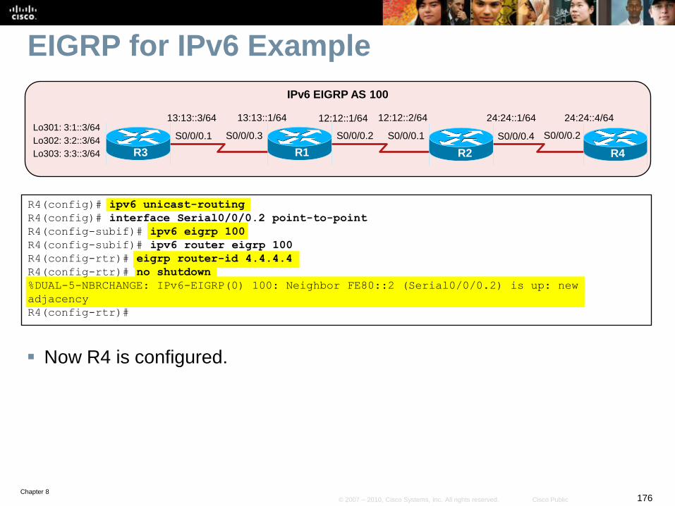
Chapter 8176© 2007 – 2010, Cisco Systems, Inc. All rights reserved. Cisco Public
EIGRP for IPv6 Example
Now R4 is configured.
S0/0/0.2 S0/0/0.1
R1
12:12::2/64
R2
IPv6 EIGRP AS 100
12:12::1/64
S0/0/0.3
13:13::1/64
R3
S0/0/0.1
13:13::3/64 24:24::4/64
R4
S0/0/0.2
24:24::1/64
S0/0/0.4Lo301: 3:1::3/64
Lo302: 3:2::3/64
Lo303: 3:3::3/64
R4(config)# ipv6 unicast-routing
R4(config)# interface Serial0/0/0.2 point-to-point
R4(config-subif)# ipv6 eigrp 100
R4(config-subif)# ipv6 router eigrp 100
R4(config-rtr)# eigrp router-id 4.4.4.4
R4(config-rtr)# no shutdown
%DUAL-5-NBRCHANGE: IPv6-EIGRP(0) 100: Neighbor FE80::2 (Serial0/0/0.2) is up: new
adjacency
R4(config-rtr)#
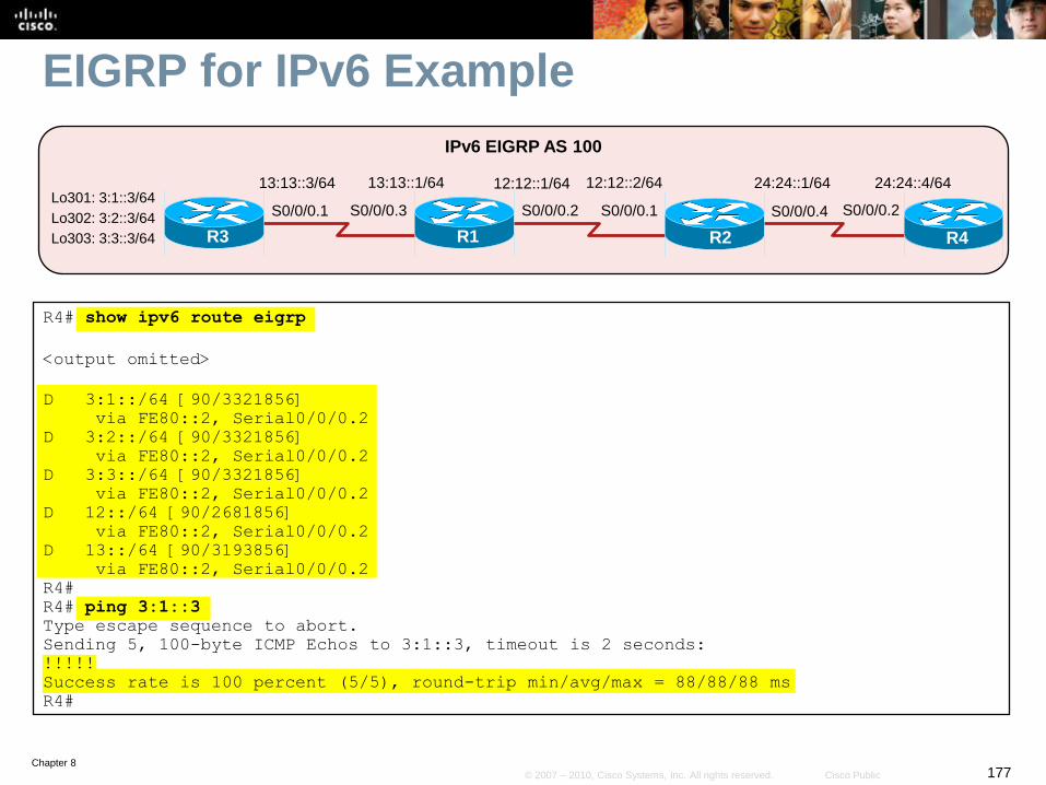
Chapter 8177© 2007 – 2010, Cisco Systems, Inc. All rights reserved. Cisco Public
EIGRP for IPv6 Example
S0/0/0.2 S0/0/0.1
R1
12:12::2/64
R2
IPv6 EIGRP AS 100
12:12::1/64
S0/0/0.3
13:13::1/64
R3
S0/0/0.1
13:13::3/64 24:24::4/64
R4
S0/0/0.2
24:24::1/64
S0/0/0.4Lo301: 3:1::3/64
Lo302: 3:2::3/64
Lo303: 3:3::3/64
R4# show ipv6 route eigrp
<output omitted>
D 3:1::/64 [90/3321856]
via FE80::2, Serial0/0/0.2
D 3:2::/64 [90/3321856]
via FE80::2, Serial0/0/0.2
D 3:3::/64 [90/3321856]
via FE80::2, Serial0/0/0.2
D 12::/64 [90/2681856]
via FE80::2, Serial0/0/0.2
D 13::/64 [90/3193856]
via FE80::2, Serial0/0/0.2
R4#
R4# ping 3:1::3
Type escape sequence to abort.
Sending 5, 100-byte ICMP Echos to 3:1::3, timeout is 2 seconds:
!!!!!
Success rate is 100 percent (5/5), round-trip min/avg/max = 88/88/88 ms
R4#
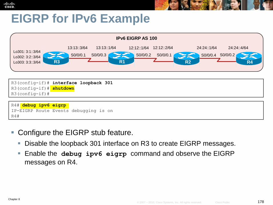
Chapter 8178© 2007 – 2010, Cisco Systems, Inc. All rights reserved. Cisco Public
EIGRP for IPv6 Example
Configure the EIGRP stub feature.
Disable the loopback 301 interface on R3 to create EIGRP messages.
Enable the debug ipv6 eigrp command and observe the EIGRP
messages on R4.
S0/0/0.2 S0/0/0.1
R1
12:12::2/64
R2
IPv6 EIGRP AS 100
12:12::1/64
S0/0/0.3
13:13::1/64
R3
S0/0/0.1
13:13::3/64 24:24::4/64
R4
S0/0/0.2
24:24::1/64
S0/0/0.4Lo301: 3:1::3/64
Lo302: 3:2::3/64
Lo303: 3:3::3/64
R3(config-if)# interface loopback 301
R3(config-if)# shutdown
R3(config-if)#
R4# debug ipv6 eigrp
IP-EIGRP Route Events debugging is on
R4#
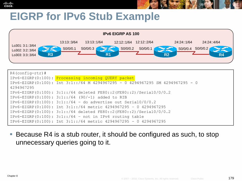
Chapter 8179© 2007 – 2010, Cisco Systems, Inc. All rights reserved. Cisco Public
EIGRP for IPv6 Stub Example
Because R4 is a stub router, it should be configured as such, to stop
unnecessary queries going to it.
S0/0/0.2 S0/0/0.1
R1
12:12::2/64
R2
IPv6 EIGRP AS 100
12:12::1/64
S0/0/0.3
13:13::1/64
R3
S0/0/0.1
13:13::3/64 24:24::4/64
R4
S0/0/0.2
24:24::1/64
S0/0/0.4Lo301: 3:1::3/64
Lo302: 3:2::3/64
Lo303: 3:3::3/64
R4(config-rtr)#
IPv6-EIGRP(0:100): Processing incoming QUERY packet
IPv6-EIGRP(0:100): Int 3:1::/64 M 4294967295 – 0 4294967295 SM 4294967295 - 0
4294967295
IPv6-EIGRP(0:100): 3:1::/64 deleted FE80::2(FE80::2)/Serial0/0/0.2
IPv6-EIGRP(0:100): 3:1::/64 (90/-1) added to RIB
IPv6-EIGRP(0:100): 3:1::/64 – do advertise out Serial0/0/0.2
IPv6-EIGRP(0:100): Int 3:1::/64 metric 4294967295 – 0 4294967295
IPv6-EIGRP(0:100): 3:1::/64 deleted FE80::2(FE80::2)/Serial0/0/0.2
IPv6-EIGRP(0:100): 3:1::/64 – not in IPv6 routing table
IPv6-EIGRP(0:100): Int 3:1::/64 metric 4294967295 – 0 4294967295
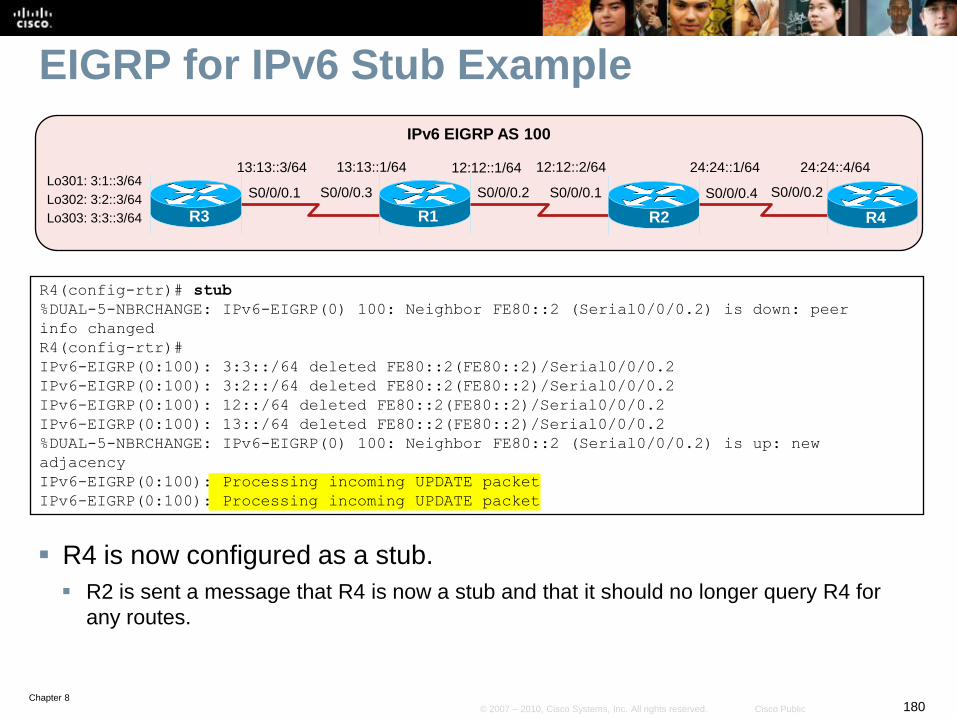
Chapter 8180© 2007 – 2010, Cisco Systems, Inc. All rights reserved. Cisco Public
EIGRP for IPv6 Stub Example
R4 is now configured as a stub.
R2 is sent a message that R4 is now a stub and that it should no longer query R4 for
any routes.
S0/0/0.2 S0/0/0.1
R1
12:12::2/64
R2
IPv6 EIGRP AS 100
12:12::1/64
S0/0/0.3
13:13::1/64
R3
S0/0/0.1
13:13::3/64 24:24::4/64
R4
S0/0/0.2
24:24::1/64
S0/0/0.4Lo301: 3:1::3/64
Lo302: 3:2::3/64
Lo303: 3:3::3/64
R4(config-rtr)# stub
%DUAL-5-NBRCHANGE: IPv6-EIGRP(0) 100: Neighbor FE80::2 (Serial0/0/0.2) is down: peer
info changed
R4(config-rtr)#
IPv6-EIGRP(0:100): 3:3::/64 deleted FE80::2(FE80::2)/Serial0/0/0.2
IPv6-EIGRP(0:100): 3:2::/64 deleted FE80::2(FE80::2)/Serial0/0/0.2
IPv6-EIGRP(0:100): 12::/64 deleted FE80::2(FE80::2)/Serial0/0/0.2
IPv6-EIGRP(0:100): 13::/64 deleted FE80::2(FE80::2)/Serial0/0/0.2
%DUAL-5-NBRCHANGE: IPv6-EIGRP(0) 100: Neighbor FE80::2 (Serial0/0/0.2) is up: new
adjacency
IPv6-EIGRP(0:100): Processing incoming UPDATE packet
IPv6-EIGRP(0:100): Processing incoming UPDATE packet
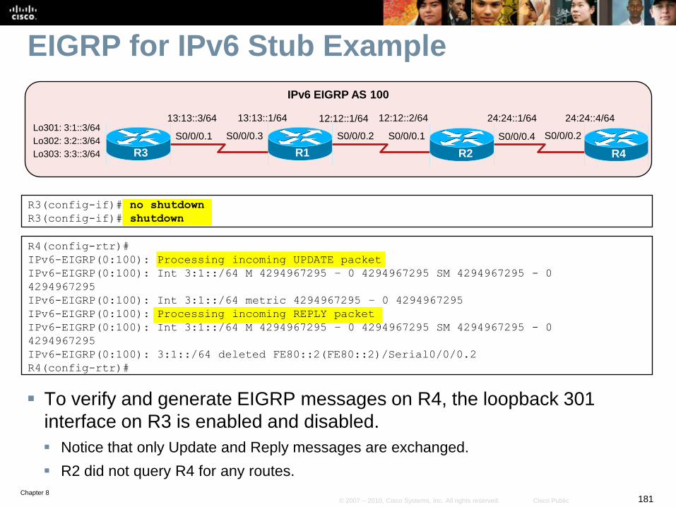
Chapter 8181© 2007 – 2010, Cisco Systems, Inc. All rights reserved. Cisco Public
EIGRP for IPv6 Stub Example
To verify and generate EIGRP messages on R4, the loopback 301
interface on R3 is enabled and disabled.
Notice that only Update and Reply messages are exchanged.
R2 did not query R4 for any routes.
S0/0/0.2 S0/0/0.1
R1
12:12::2/64
R2
IPv6 EIGRP AS 100
12:12::1/64
S0/0/0.3
13:13::1/64
R3
S0/0/0.1
13:13::3/64 24:24::4/64
R4
S0/0/0.2
24:24::1/64
S0/0/0.4Lo301: 3:1::3/64
Lo302: 3:2::3/64
Lo303: 3:3::3/64
R3(config-if)# no shutdown
R3(config-if)# shutdown
R4(config-rtr)#
IPv6-EIGRP(0:100): Processing incoming UPDATE packet
IPv6-EIGRP(0:100): Int 3:1::/64 M 4294967295 – 0 4294967295 SM 4294967295 - 0
4294967295
IPv6-EIGRP(0:100): Int 3:1::/64 metric 4294967295 – 0 4294967295
IPv6-EIGRP(0:100): Processing incoming REPLY packet
IPv6-EIGRP(0:100): Int 3:1::/64 M 4294967295 – 0 4294967295 SM 4294967295 - 0
4294967295
IPv6-EIGRP(0:100): 3:1::/64 deleted FE80::2(FE80::2)/Serial0/0/0.2
R4(config-rtr)#
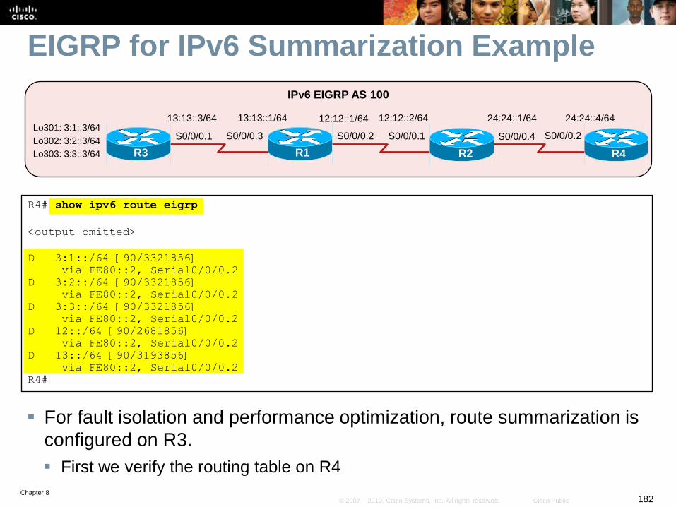
Chapter 8182© 2007 – 2010, Cisco Systems, Inc. All rights reserved. Cisco Public
EIGRP for IPv6 Summarization Example
For fault isolation and performance optimization, route summarization is
configured on R3.
First we verify the routing table on R4
S0/0/0.2 S0/0/0.1
R1
12:12::2/64
R2
IPv6 EIGRP AS 100
12:12::1/64
S0/0/0.3
13:13::1/64
R3
S0/0/0.1
13:13::3/64 24:24::4/64
R4
S0/0/0.2
24:24::1/64
S0/0/0.4Lo301: 3:1::3/64
Lo302: 3:2::3/64
Lo303: 3:3::3/64
R4# show ipv6 route eigrp
<output omitted>
D 3:1::/64 [90/3321856]
via FE80::2, Serial0/0/0.2
D 3:2::/64 [90/3321856]
via FE80::2, Serial0/0/0.2
D 3:3::/64 [90/3321856]
via FE80::2, Serial0/0/0.2
D 12::/64 [90/2681856]
via FE80::2, Serial0/0/0.2
D 13::/64 [90/3193856]
via FE80::2, Serial0/0/0.2
R4#
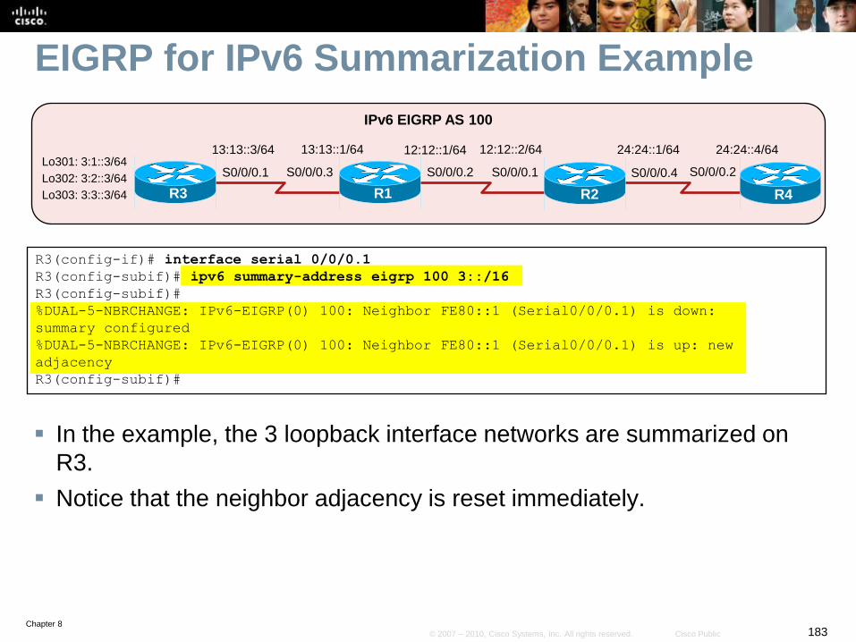
Chapter 8183© 2007 – 2010, Cisco Systems, Inc. All rights reserved. Cisco Public
EIGRP for IPv6 Summarization Example
In the example, the 3 loopback interface networks are summarized on
R3.
Notice that the neighbor adjacency is reset immediately.
S0/0/0.2 S0/0/0.1
R1
12:12::2/64
R2
IPv6 EIGRP AS 100
12:12::1/64
S0/0/0.3
13:13::1/64
R3
S0/0/0.1
13:13::3/64 24:24::4/64
R4
S0/0/0.2
24:24::1/64
S0/0/0.4Lo301: 3:1::3/64
Lo302: 3:2::3/64
Lo303: 3:3::3/64
R3(config-if)# interface serial 0/0/0.1
R3(config-subif)# ipv6 summary-address eigrp 100 3::/16
R3(config-subif)#
%DUAL-5-NBRCHANGE: IPv6-EIGRP(0) 100: Neighbor FE80::1 (Serial0/0/0.1) is down:
summary configured
%DUAL-5-NBRCHANGE: IPv6-EIGRP(0) 100: Neighbor FE80::1 (Serial0/0/0.1) is up: new
adjacency
R3(config-subif)#
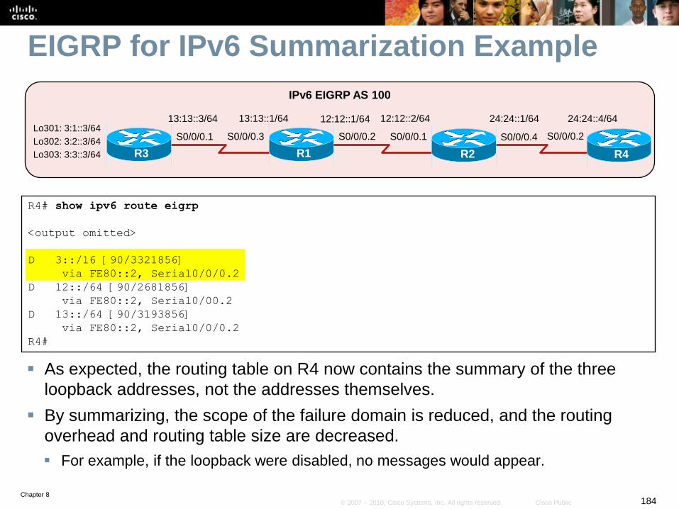
Chapter 8184© 2007 – 2010, Cisco Systems, Inc. All rights reserved. Cisco Public
EIGRP for IPv6 Summarization Example
As expected, the routing table on R4 now contains the summary of the three
loopback addresses, not the addresses themselves.
By summarizing, the scope of the failure domain is reduced, and the routing
overhead and routing table size are decreased.
For example, if the loopback were disabled, no messages would appear.
S0/0/0.2 S0/0/0.1
R1
12:12::2/64
R2
IPv6 EIGRP AS 100
12:12::1/64
S0/0/0.3
13:13::1/64
R3
S0/0/0.1
13:13::3/64 24:24::4/64
R4
S0/0/0.2
24:24::1/64
S0/0/0.4Lo301: 3:1::3/64
Lo302: 3:2::3/64
Lo303: 3:3::3/64
R4# show ipv6 route eigrp
<output omitted>
D 3::/16 [90/3321856]
via FE80::2, Serial0/0/0.2
D 12::/64 [90/2681856]
via FE80::2, Serial0/00.2
D 13::/64 [90/3193856]
via FE80::2, Serial0/0/0.2
R4#
Chapter 8185© 2007 – 2010, Cisco Systems, Inc. All rights reserved. Cisco Public
Multiprotocol BGP (MP-BGP)
Chapter 8186© 2007 – 2010, Cisco Systems, Inc. All rights reserved. Cisco Public
Multiprotocol BGP (MP-BGP)
Multiprotocol BGP is used to enable BGP4 to carry the
information of other protocols such as Multiprotocol Label
Switching (MPLS) and IPv6.
• RFC 4760 defines multiprotocol extensions for BGP-4.
• RFC 2545 defines how these extensions are used for IPv6.
MBGP operates with multiple protocols by identifying two
separate protocols:
• The carrier protocol
• The passenger protocol
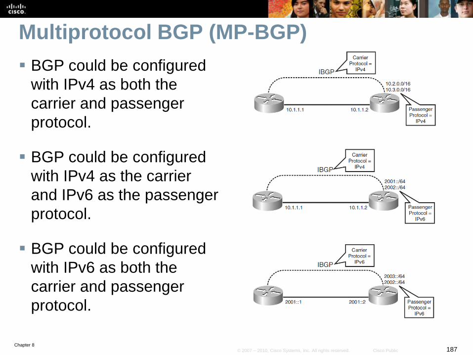
Chapter 8187© 2007 – 2010, Cisco Systems, Inc. All rights reserved. Cisco Public
Multiprotocol BGP (MP-BGP)
BGP could be configured
with IPv4 as both the
carrier and passenger
protocol.
BGP could be configured
with IPv4 as the carrier
and IPv6 as the passenger
protocol.
BGP could be configured
with IPv6 as both the
carrier and passenger
protocol.
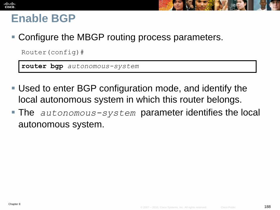
Chapter 8188© 2007 – 2010, Cisco Systems, Inc. All rights reserved. Cisco Public
Enable BGP
Configure the MBGP routing process parameters.
Router(config)#
router bgp autonomous-system
Used to enter BGP configuration mode, and identify the
local autonomous system in which this router belongs.
The autonomous-system parameter identifies the local
autonomous system.
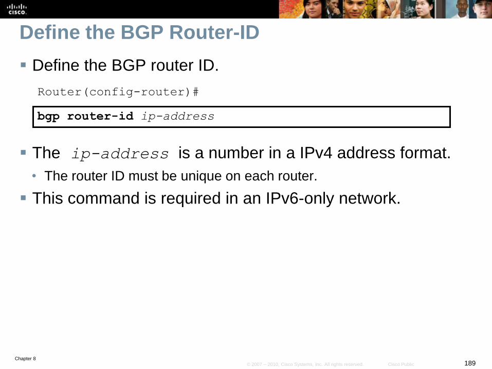
Chapter 8189© 2007 – 2010, Cisco Systems, Inc. All rights reserved. Cisco Public
Define the BGP Router-ID
Define the BGP router ID.
Router(config-router)#
bgp router-id ip-address
The ip-address is a number in a IPv4 address format.
• The router ID must be unique on each router.
This command is required in an IPv6-only network.
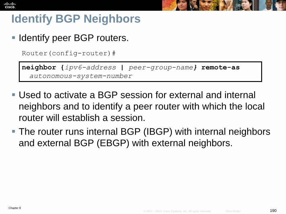
Chapter 8190© 2007 – 2010, Cisco Systems, Inc. All rights reserved. Cisco Public
Identify BGP Neighbors
Identify peer BGP routers.
Router(config-router)#
neighbor {ipv6-address | peer-group-name} remote-as
autonomous-system-number
Used to activate a BGP session for external and internal
neighbors and to identify a peer router with which the local
router will establish a session.
The router runs internal BGP (IBGP) with internal neighbors
and external BGP (EBGP) with external neighbors.
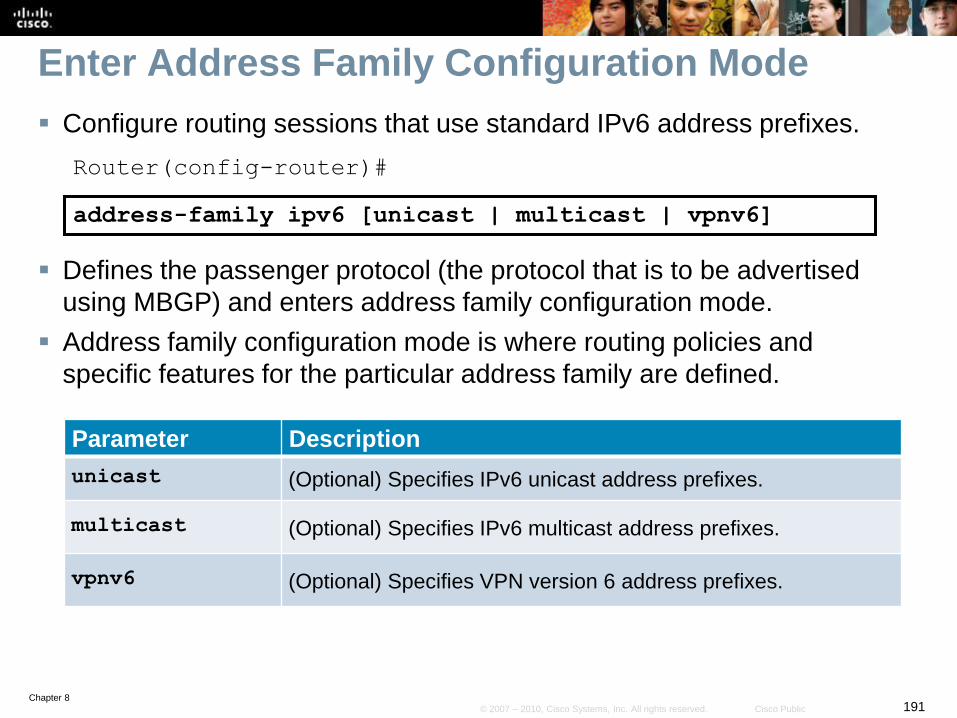
Chapter 8191© 2007 – 2010, Cisco Systems, Inc. All rights reserved. Cisco Public
Enter Address Family Configuration Mode
Configure routing sessions that use standard IPv6 address prefixes.
Router(config-router)#
address-family ipv6 [unicast | multicast | vpnv6]
Defines the passenger protocol (the protocol that is to be advertised
using MBGP) and enters address family configuration mode.
Address family configuration mode is where routing policies and
specific features for the particular address family are defined.
Parameter Description
unicast (Optional) Specifies IPv6 unicast address prefixes.
multicast (Optional) Specifies IPv6 multicast address prefixes.
vpnv6 (Optional) Specifies VPN version 6 address prefixes.
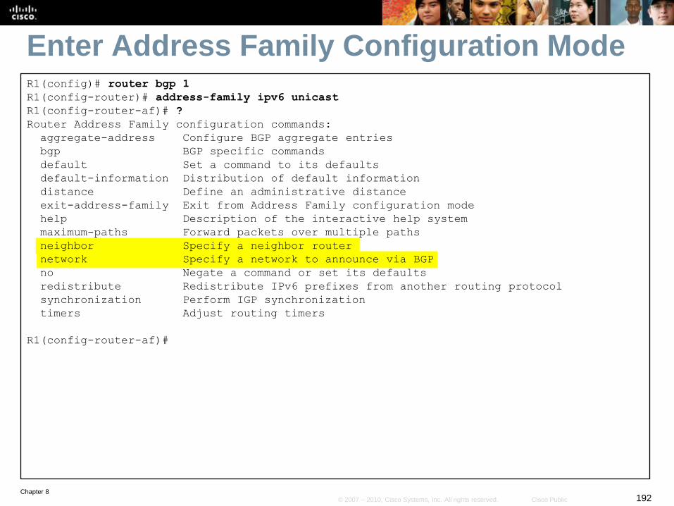
Chapter 8192© 2007 – 2010, Cisco Systems, Inc. All rights reserved. Cisco Public
Enter Address Family Configuration ModeR1(config)# router bgp 1
R1(config-router)# address-family ipv6 unicast
R1(config-router-af)# ?
Router Address Family configuration commands:
aggregate-address Configure BGP aggregate entries
bgp BGP specific commands
default Set a command to its defaults
default-information Distribution of default information
distance Define an administrative distance
exit-address-family Exit from Address Family configuration mode
help Description of the interactive help system
maximum-paths Forward packets over multiple paths
neighbor Specify a neighbor router
network Specify a network to announce via BGP
no Negate a command or set its defaults
redistribute Redistribute IPv6 prefixes from another routing protocol
synchronization Perform IGP synchronization
timers Adjust routing timers
R1(config-router-af)#
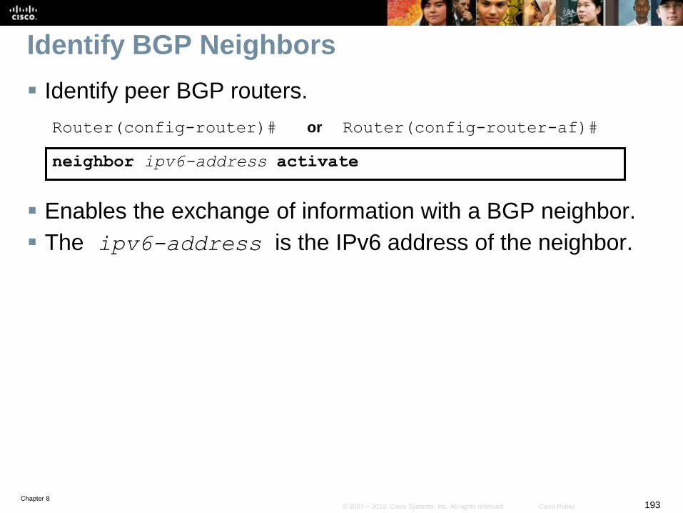
Chapter 8193© 2007 – 2010, Cisco Systems, Inc. All rights reserved. Cisco Public
Identify BGP Neighbors
Identify peer BGP routers.
Router(config-router)# or Router(config-router-af)#
neighbor ipv6-address activate
Enables the exchange of information with a BGP neighbor.
The ipv6-address is the IPv6 address of the neighbor.

Chapter 8194© 2007 – 2010, Cisco Systems, Inc. All rights reserved. Cisco Public
Identify BGP Neighbors
Identify peer BGP routers.
Router(config-router)# or Router(config-router-af)#
network network-number
Specifies the networks to be advertised by the BGP and MBGP routing process in the network-number
parameter.
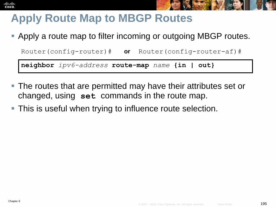
Chapter 8195© 2007 – 2010, Cisco Systems, Inc. All rights reserved. Cisco Public
Apply Route Map to MBGP Routes
Apply a route map to filter incoming or outgoing MBGP routes.
Router(config-router)# or Router(config-router-af)#
neighbor ipv6-address route-map name {in | out}
The routes that are permitted may have their attributes set or changed, using set commands in the route map.
This is useful when trying to influence route selection.
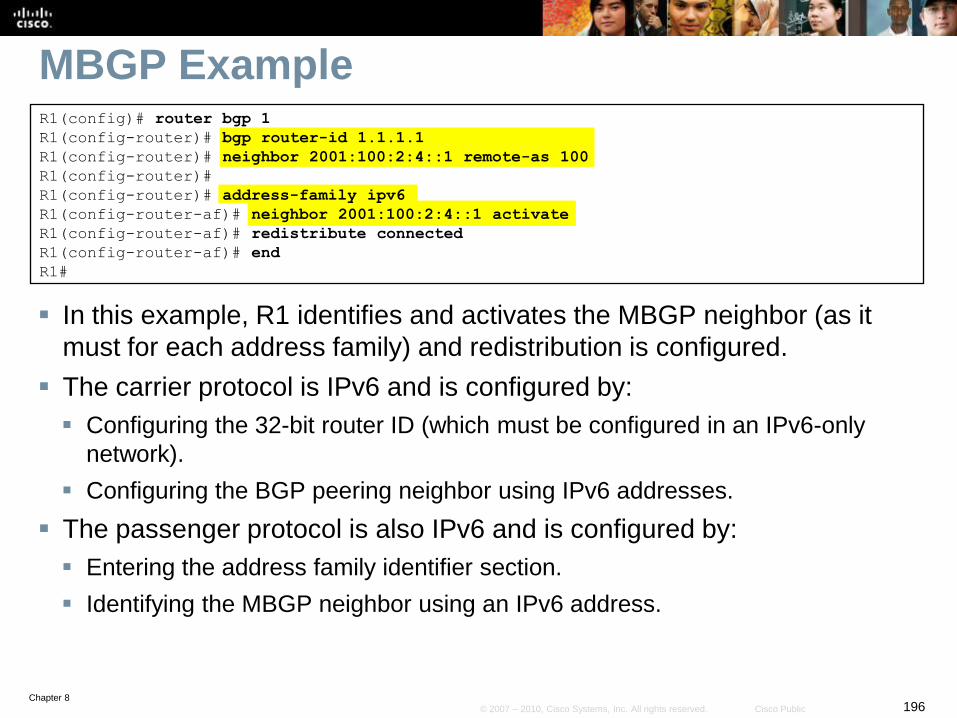
Chapter 8196© 2007 – 2010, Cisco Systems, Inc. All rights reserved. Cisco Public
MBGP Example
In this example, R1 identifies and activates the MBGP neighbor (as it
must for each address family) and redistribution is configured.
The carrier protocol is IPv6 and is configured by:
Configuring the 32-bit router ID (which must be configured in an IPv6-only
network).
Configuring the BGP peering neighbor using IPv6 addresses.
The passenger protocol is also IPv6 and is configured by:
Entering the address family identifier section.
Identifying the MBGP neighbor using an IPv6 address.
R1(config)# router bgp 1
R1(config-router)# bgp router-id 1.1.1.1
R1(config-router)# neighbor 2001:100:2:4::1 remote-as 100
R1(config-router)#
R1(config-router)# address-family ipv6
R1(config-router-af)# neighbor 2001:100:2:4::1 activate
R1(config-router-af)# redistribute connected
R1(config-router-af)# end
R1#

Chapter 8197© 2007 – 2010, Cisco Systems, Inc. All rights reserved. Cisco Public
IPv6 PBR
Chapter 8198© 2007 – 2010, Cisco Systems, Inc. All rights reserved. Cisco Public
Policy-Based Routing (PBR)
PBR is sometimes called traffic engineering and helps to
provide a high degree of control over routing.
PBR is available for both IPv4 and IPv6.
PBR can be used to:
• Manually configurr the path that packets take.
• Classify and mark packets
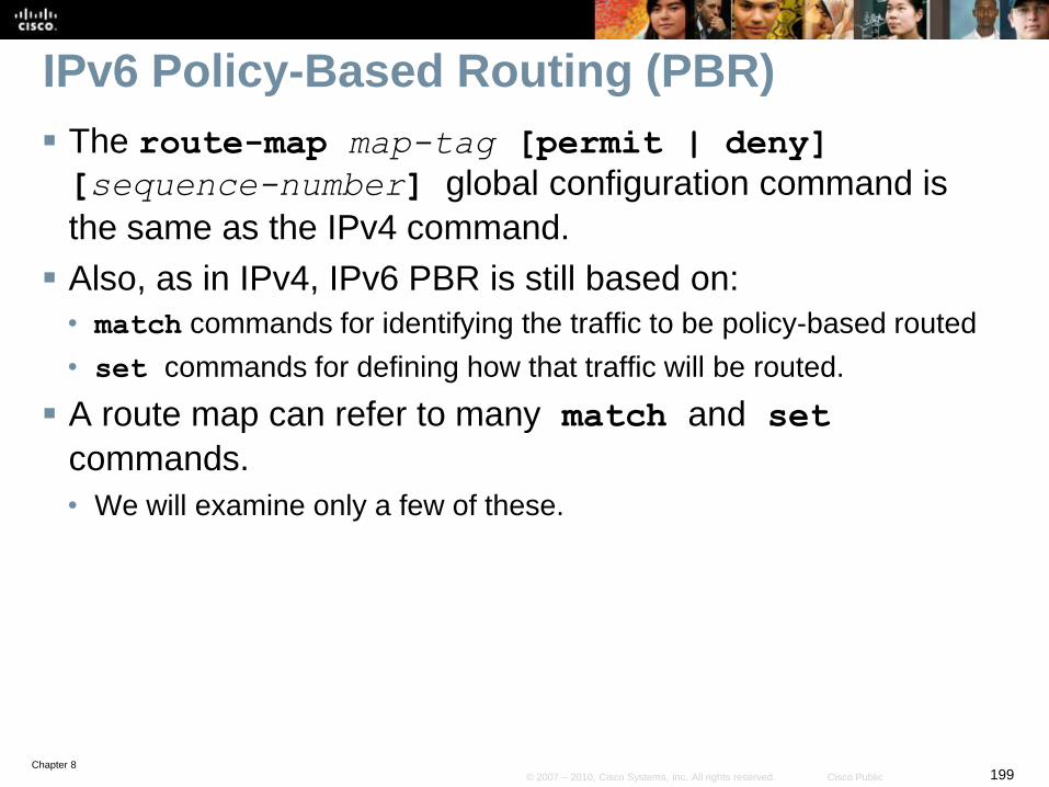
Chapter 8199© 2007 – 2010, Cisco Systems, Inc. All rights reserved. Cisco Public
IPv6 Policy-Based Routing (PBR)
The route-map map-tag [permit | deny]
[sequence-number] global configuration command is
the same as the IPv4 command.
Also, as in IPv4, IPv6 PBR is still based on:
• match commands for identifying the traffic to be policy-based routed
• set commands for defining how that traffic will be routed.
A route map can refer to many match and set
commands.
• We will examine only a few of these.
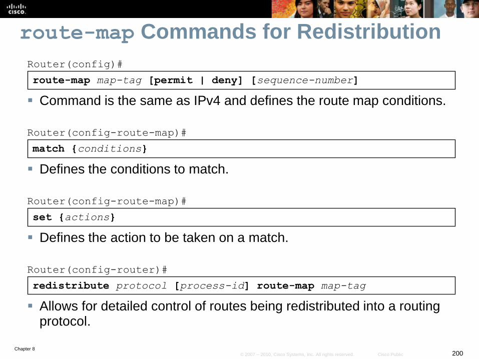
Chapter 8200© 2007 – 2010, Cisco Systems, Inc. All rights reserved. Cisco Public
redistribute protocol [process-id] route-map map-tag
Router(config-router)#
Allows for detailed control of routes being redistributed into a routing protocol.
route-map Commands for Redistribution
route-map map-tag [permit | deny] [sequence-number]
Router(config)#
Command is the same as IPv4 and defines the route map conditions.
match {conditions}
Router(config-route-map)#
Defines the conditions to match.
set {actions}
Router(config-route-map)#
Defines the action to be taken on a match.
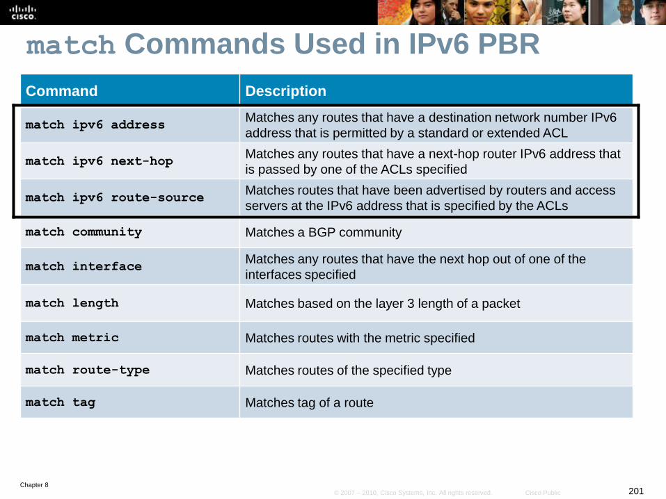
Chapter 8201© 2007 – 2010, Cisco Systems, Inc. All rights reserved. Cisco Public
match Commands Used in IPv6 PBR
Command Description
match ipv6 addressMatches any routes that have a destination network number IPv6
address that is permitted by a standard or extended ACL
match ipv6 next-hopMatches any routes that have a next-hop router IPv6 address that
is passed by one of the ACLs specified
match ipv6 route-sourceMatches routes that have been advertised by routers and access
servers at the IPv6 address that is specified by the ACLs
match community Matches a BGP community
match interfaceMatches any routes that have the next hop out of one of the
interfaces specified
match length Matches based on the layer 3 length of a packet
match metric Matches routes with the metric specified
match route-type Matches routes of the specified type
match tag Matches tag of a route
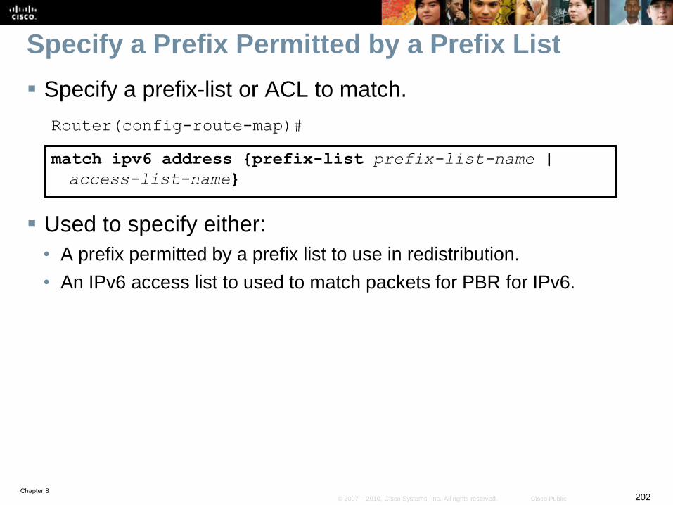
Chapter 8202© 2007 – 2010, Cisco Systems, Inc. All rights reserved. Cisco Public
Specify a Prefix Permitted by a Prefix List
Specify a prefix-list or ACL to match.
Router(config-route-map)#
match ipv6 address {prefix-list prefix-list-name |
access-list-name}
Used to specify either:
• A prefix permitted by a prefix list to use in redistribution.
• An IPv6 access list to used to match packets for PBR for IPv6.
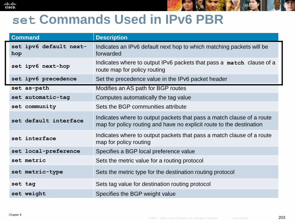
Chapter 8203© 2007 – 2010, Cisco Systems, Inc. All rights reserved. Cisco Public
set Commands Used in IPv6 PBR
Command Description
set ipv6 default next-
hop
Indicates an IPv6 default next hop to which matching packets will be
forwarded
set ipv6 next-hopIndicates where to output IPv6 packets that pass a match clause of a
route map for policy routing
set ipv6 precedence Set the precedence value in the IPv6 packet header
set as-path Modifies an AS path for BGP routes
set automatic-tag Computes automatically the tag value
set community Sets the BGP communities attribute
set default interfaceIndicates where to output packets that pass a match clause of a route
map for policy routing and have no explicit route to the destination
set interfaceIndicates where to output packets that pass a match clause of a route
map for policy routing
set local-preference Specifies a BGP local preference value
set metric Sets the metric value for a routing protocol
set metric-type Sets the metric type for the destination routing protocol
set tag Sets tag value for destination routing protocol
set weight Specifies the BGP weight value
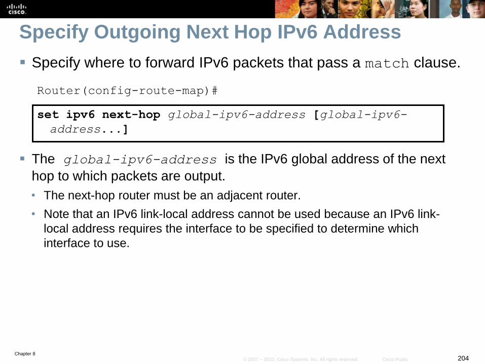
Chapter 8204© 2007 – 2010, Cisco Systems, Inc. All rights reserved. Cisco Public
Specify Outgoing Next Hop IPv6 Address
Specify where to forward IPv6 packets that pass a match clause.
Router(config-route-map)#
set ipv6 next-hop global-ipv6-address [global-ipv6-
address...]
The global-ipv6-address is the IPv6 global address of the next
hop to which packets are output.
• The next-hop router must be an adjacent router.
• Note that an IPv6 link-local address cannot be used because an IPv6 link-
local address requires the interface to be specified to determine which
interface to use.
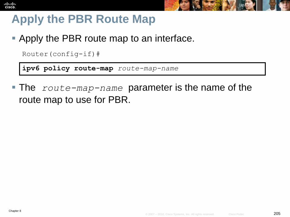
Chapter 8205© 2007 – 2010, Cisco Systems, Inc. All rights reserved. Cisco Public
Apply the PBR Route Map
Apply the PBR route map to an interface.
Router(config-if)#
ipv6 policy route-map route-map-name
The route-map-name parameter is the name of the
route map to use for PBR.
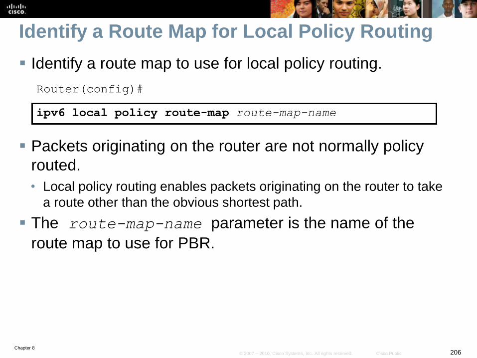
Chapter 8206© 2007 – 2010, Cisco Systems, Inc. All rights reserved. Cisco Public
Identify a Route Map for Local Policy Routing
Identify a route map to use for local policy routing.
Router(config)#
ipv6 local policy route-map route-map-name
Packets originating on the router are not normally policy
routed.
• Local policy routing enables packets originating on the router to take
a route other than the obvious shortest path.
The route-map-name parameter is the name of the
route map to use for PBR.
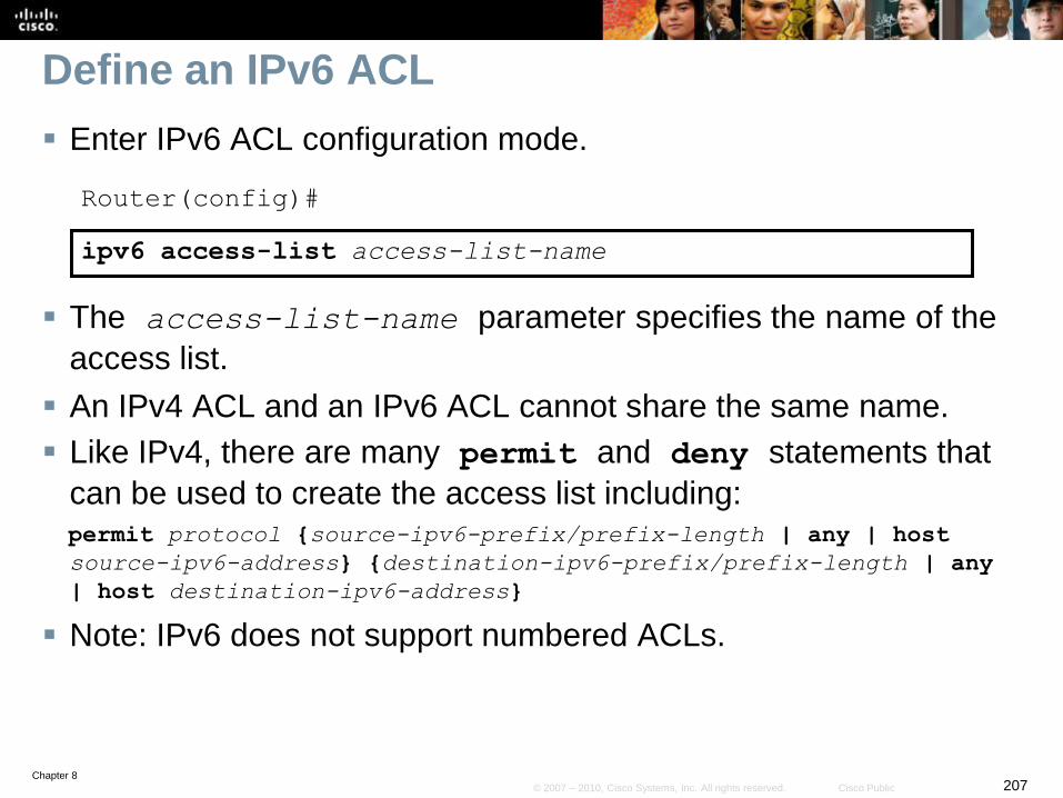
Chapter 8207© 2007 – 2010, Cisco Systems, Inc. All rights reserved. Cisco Public
Define an IPv6 ACL
Enter IPv6 ACL configuration mode.
Router(config)#
ipv6 access-list access-list-name
The access-list-name parameter specifies the name of the
access list.
An IPv4 ACL and an IPv6 ACL cannot share the same name.
Like IPv4, there are many permit and deny statements that
can be used to create the access list including:permit protocol {source-ipv6-prefix/prefix-length | any | host
source-ipv6-address} {destination-ipv6-prefix/prefix-length | any
| host destination-ipv6-address}
Note: IPv6 does not support numbered ACLs.
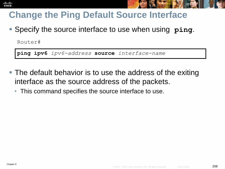
Chapter 8208© 2007 – 2010, Cisco Systems, Inc. All rights reserved. Cisco Public
Change the Ping Default Source Interface
Specify the source interface to use when using ping.
Router#
ping ipv6 ipv6-address source interface-name
The default behavior is to use the address of the exiting
interface as the source address of the packets.
• This command specifies the source interface to use.
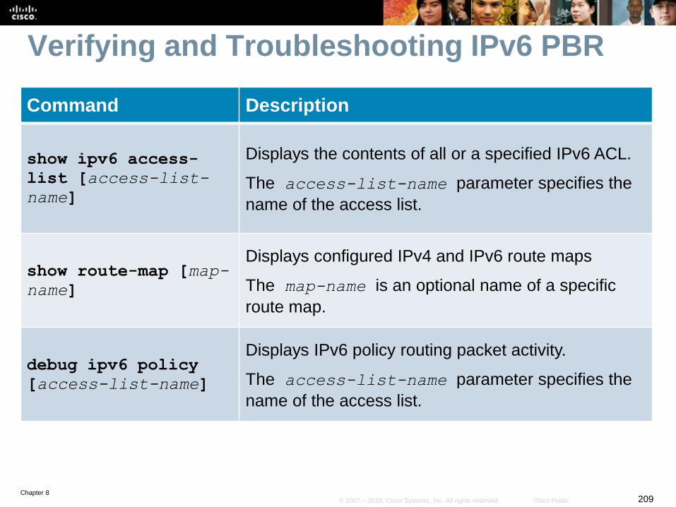
Chapter 8209© 2007 – 2010, Cisco Systems, Inc. All rights reserved. Cisco Public
Verifying and Troubleshooting IPv6 PBR
Command Description
show ipv6 access-
list [access-list-
name]
Displays the contents of all or a specified IPv6 ACL.
The access-list-name parameter specifies the
name of the access list.
show route-map [map-
name]
Displays configured IPv4 and IPv6 route maps
The map-name is an optional name of a specific
route map.
debug ipv6 policy
[access-list-name]
Displays IPv6 policy routing packet activity.
The access-list-name parameter specifies the
name of the access list.
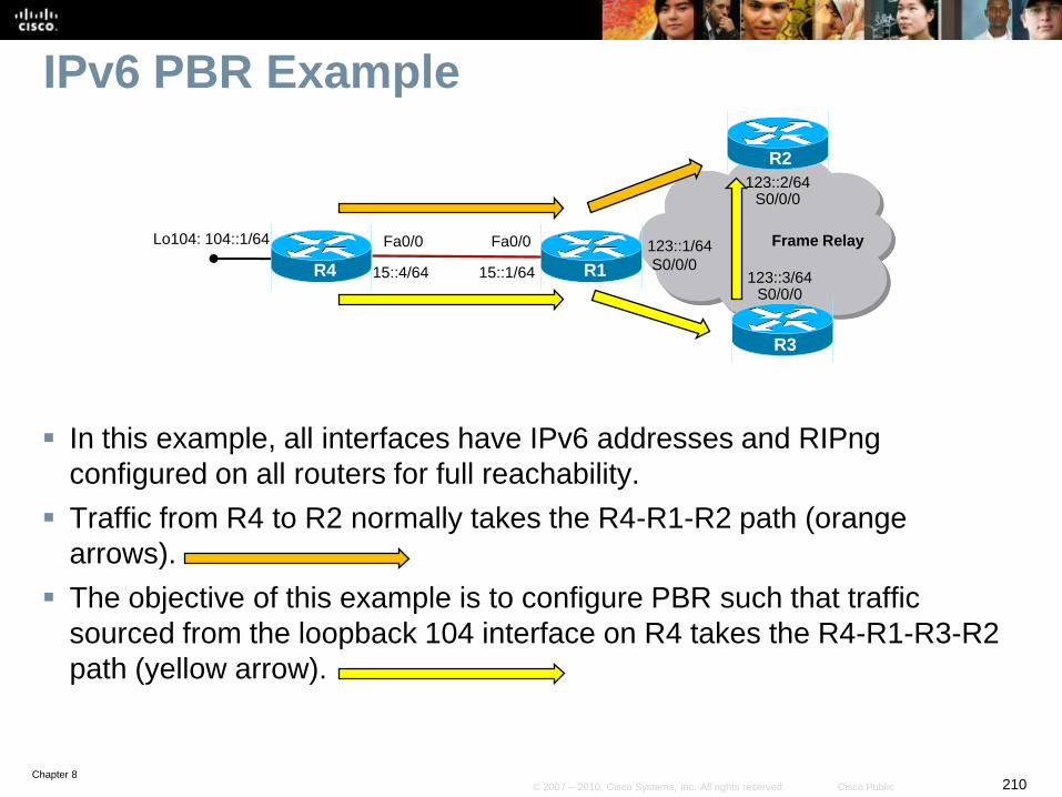
Chapter 8210© 2007 – 2010, Cisco Systems, Inc. All rights reserved. Cisco Public
IPv6 PBR Example
In this example, all interfaces have IPv6 addresses and RIPng
configured on all routers for full reachability.
Traffic from R4 to R2 normally takes the R4-R1-R2 path (orange
arrows).
The objective of this example is to configure PBR such that traffic
sourced from the loopback 104 interface on R4 takes the R4-R1-R3-R2
path (yellow arrow).
R1
R2
R3
15::4/64
Fa0/0
S0/0/0R4
Fa0/0
15::1/64
Lo104: 104::1/64 123::1/64
123::2/64S0/0/0
123::3/64S0/0/0
Frame Relay
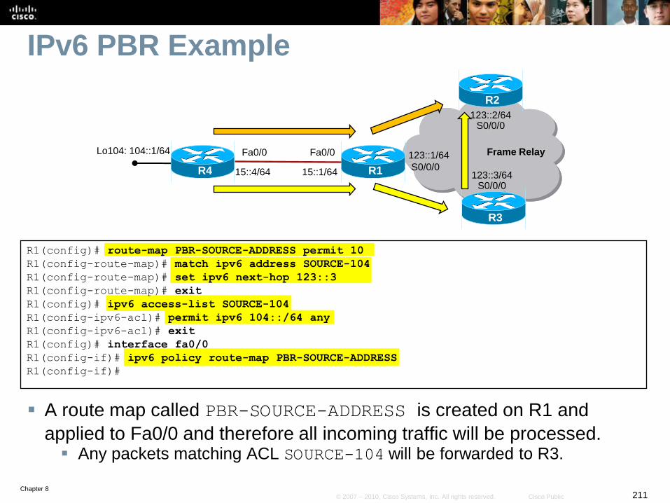
Chapter 8211© 2007 – 2010, Cisco Systems, Inc. All rights reserved. Cisco Public
IPv6 PBR Example
R1(config)# route-map PBR-SOURCE-ADDRESS permit 10
R1(config-route-map)# match ipv6 address SOURCE-104
R1(config-route-map)# set ipv6 next-hop 123::3
R1(config-route-map)# exit
R1(config)# ipv6 access-list SOURCE-104
R1(config-ipv6-acl)# permit ipv6 104::/64 any
R1(config-ipv6-acl)# exit
R1(config)# interface fa0/0
R1(config-if)# ipv6 policy route-map PBR-SOURCE-ADDRESS
R1(config-if)#
A route map called PBR-SOURCE-ADDRESS is created on R1 and
applied to Fa0/0 and therefore all incoming traffic will be processed. Any packets matching ACL SOURCE-104 will be forwarded to R3.
R1
R2
R3
15::4/64
Fa0/0
S0/0/0R4
Fa0/0
15::1/64
Lo104: 104::1/64 123::1/64
123::2/64S0/0/0
123::3/64S0/0/0
Frame Relay
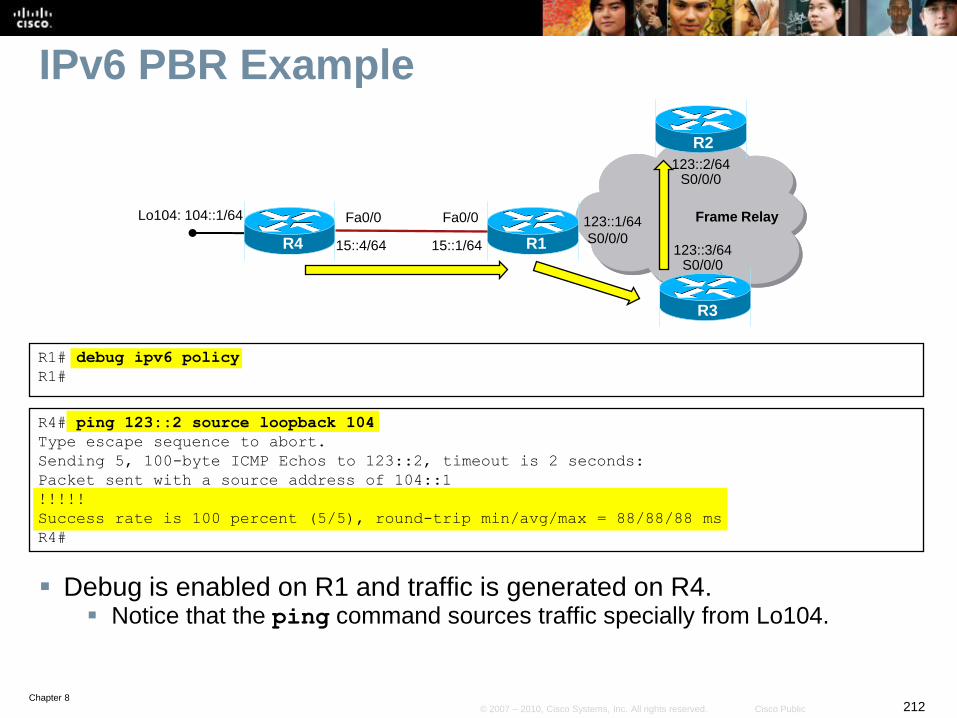
Chapter 8212© 2007 – 2010, Cisco Systems, Inc. All rights reserved. Cisco Public
IPv6 PBR Example
R1# debug ipv6 policy
R1#
R4# ping 123::2 source loopback 104
Type escape sequence to abort.
Sending 5, 100-byte ICMP Echos to 123::2, timeout is 2 seconds:
Packet sent with a source address of 104::1
!!!!!
Success rate is 100 percent (5/5), round-trip min/avg/max = 88/88/88 ms
R4#
Debug is enabled on R1 and traffic is generated on R4. Notice that the ping command sources traffic specially from Lo104.
R1
R2
R3
15::4/64
Fa0/0
S0/0/0R4
Fa0/0
15::1/64
Lo104: 104::1/64 123::1/64
123::2/64S0/0/0
123::3/64S0/0/0
Frame Relay
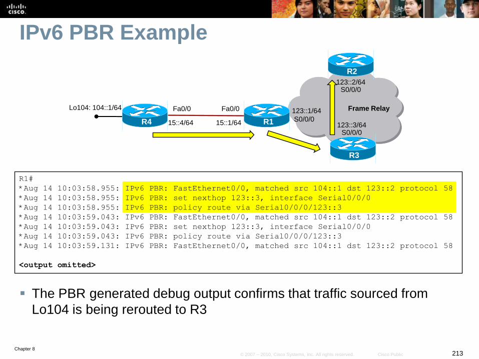
Chapter 8213© 2007 – 2010, Cisco Systems, Inc. All rights reserved. Cisco Public
IPv6 PBR Example
R1#
*Aug 14 10:03:58.955: IPv6 PBR: FastEthernet0/0, matched src 104::1 dst 123::2 protocol 58
*Aug 14 10:03:58.955: IPv6 PBR: set nexthop 123::3, interface Serial0/0/0
*Aug 14 10:03:58.955: IPv6 PBR: policy route via Serial0/0/0/123::3
*Aug 14 10:03:59.043: IPv6 PBR: FastEthernet0/0, matched src 104::1 dst 123::2 protocol 58
*Aug 14 10:03:59.043: IPv6 PBR: set nexthop 123::3, interface Serial0/0/0
*Aug 14 10:03:59.043: IPv6 PBR: policy route via Serial0/0/0/123::3
*Aug 14 10:03:59.131: IPv6 PBR: FastEthernet0/0, matched src 104::1 dst 123::2 protocol 58
<output omitted>
The PBR generated debug output confirms that traffic sourced from
Lo104 is being rerouted to R3
R1
R2
R3
15::4/64
Fa0/0
S0/0/0R4
Fa0/0
15::1/64
Lo104: 104::1/64 123::1/64
123::2/64S0/0/0
123::3/64S0/0/0
Frame Relay
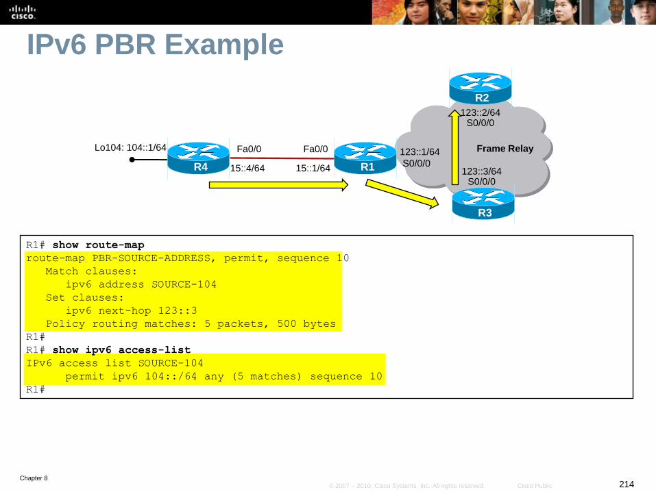
Chapter 8214© 2007 – 2010, Cisco Systems, Inc. All rights reserved. Cisco Public
IPv6 PBR Example
R1# show route-map
route-map PBR-SOURCE-ADDRESS, permit, sequence 10
Match clauses:
ipv6 address SOURCE-104
Set clauses:
ipv6 next-hop 123::3
Policy routing matches: 5 packets, 500 bytes
R1#
R1# show ipv6 access-list
IPv6 access list SOURCE-104
permit ipv6 104::/64 any (5 matches) sequence 10
R1#
R1
R2
R3
15::4/64
Fa0/0
S0/0/0R4
Fa0/0
15::1/64
Lo104: 104::1/64 123::1/64
123::2/64S0/0/0
123::3/64S0/0/0
Frame Relay

Chapter 8215© 2007 – 2010, Cisco Systems, Inc. All rights reserved. Cisco Public
IPv6 Redistribution
Chapter 8216© 2007 – 2010, Cisco Systems, Inc. All rights reserved. Cisco Public
Redistribution
Redistribution can be configured between:
• Two different RIPng processes
• RIPng and OSPFv3 (one or two-way)
• RIPng and MBGP (one or two-way)
• OSPF and MBGP (one or two-way)
Chapter 8217© 2007 – 2010, Cisco Systems, Inc. All rights reserved. Cisco Public
RIPng Redistribution Considerations
IPv6 IGPs can have multiple instances running on the same
router, and on the same interface.
• By default, these instances use the same multicast group and the
same port number and accept updates from each other.
However, if the port number or the multicast group address
are changed, the instances will not communicate by default.
• Redistribution can be configured so that the instances share their
routes.
The seed metric used in redistributed routes defaults to one
hop, and can be changed using route maps.
Chapter 8218© 2007 – 2010, Cisco Systems, Inc. All rights reserved. Cisco Public
RIPng Redistribution Considerations
Multiple RIPng instances can run simultaneously on the
same router and on the same link.
By default, these multiple instances of RIPng will send and
receive advertisements between each other.
To separate these processes, use the following router
configuration command:
• port port-number multicast-group multicast-address
Redistribution must be configured to share information
between these separate processes.
Seed metrics may need to be configured to control paths.
Chapter 8219© 2007 – 2010, Cisco Systems, Inc. All rights reserved. Cisco Public
OSPFv3 Redistribution Considerations
OSPFv3 does not redistribute connected networks by
default.
The metric and metric type may be reset when
redistributing.
• The solution is to explicitly configure the seed metric and metric type.
Redistribution may cause suboptimal routing and routing
loops.
• Solutions include changing administrative distance and route filtering.
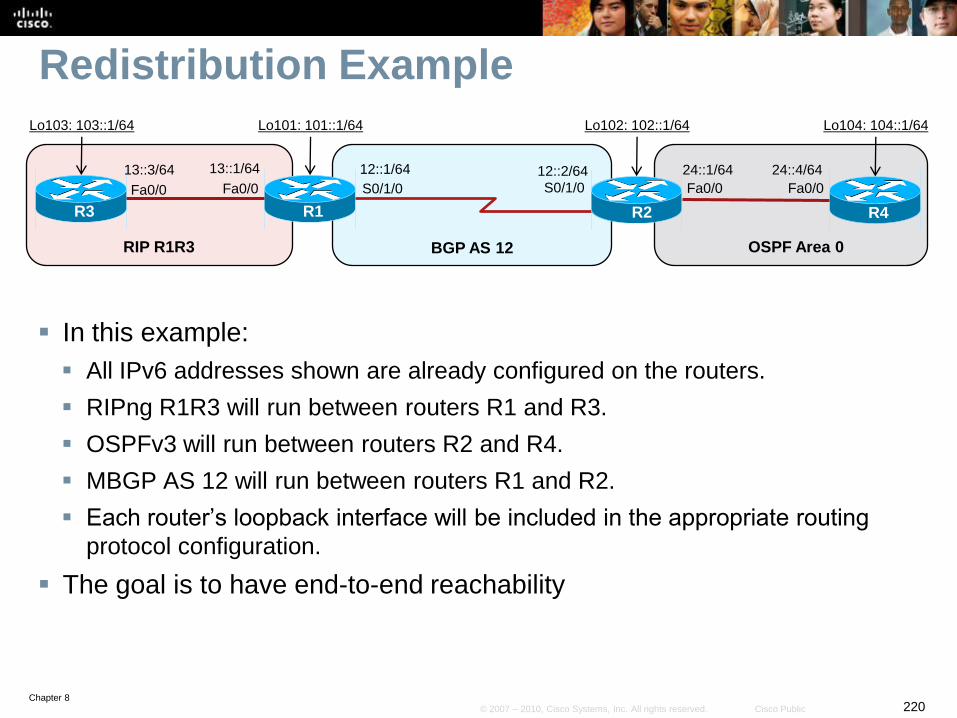
Chapter 8220© 2007 – 2010, Cisco Systems, Inc. All rights reserved. Cisco Public
Redistribution Example
In this example:
All IPv6 addresses shown are already configured on the routers.
RIPng R1R3 will run between routers R1 and R3.
OSPFv3 will run between routers R2 and R4.
MBGP AS 12 will run between routers R1 and R2.
Each router’s loopback interface will be included in the appropriate routing
protocol configuration.
The goal is to have end-to-end reachability
S0/1/0 S0/1/0
R1
12::2/64
R2
RIP R1R3 BGP AS 12
12::1/64
Fa0/0
13::1/64
R3
Fa0/0
13::3/64
OSPF Area 0
24::4/64
R4
Fa0/0
24::1/64
Fa0/0
Lo103: 103::1/64 Lo101: 101::1/64 Lo102: 102::1/64 Lo104: 104::1/64

Chapter 8221© 2007 – 2010, Cisco Systems, Inc. All rights reserved. Cisco Public
Redistribution Example
IPv6 unicast routing is enabled and RIPng R1R3 is configured on the
interfaces to be included in the RIPng process.
R1(config)# ipv6 unicast-routing
R1(config)# interface fa0/0
R1(config-if)# ipv6 rip R1R3 enable
R1(config-if)#
R3(config)# ipv6 unicast-routing
R3(config)# interface fa0/0
R3(config-if)# ipv6 rip R1R3 enable
R3(config-subif)# exit
R3(config)# interface loopback 103
R3(config-if)# ipv6 rip R1R3 enable
R3(config-if)#
S0/1/0 S0/1/0
R1
12::2/64
R2
RIP R1R3 BGP AS 12
12::1/64
Fa0/0
13::1/64
R3
Fa0/0
13::3/64
OSPF Area 0
24::4/64
R4
Fa0/0
24::1/64
Fa0/0
Lo103: 103::1/64 Lo101: 101::1/64 Lo102: 102::1/64 Lo104: 104::1/64
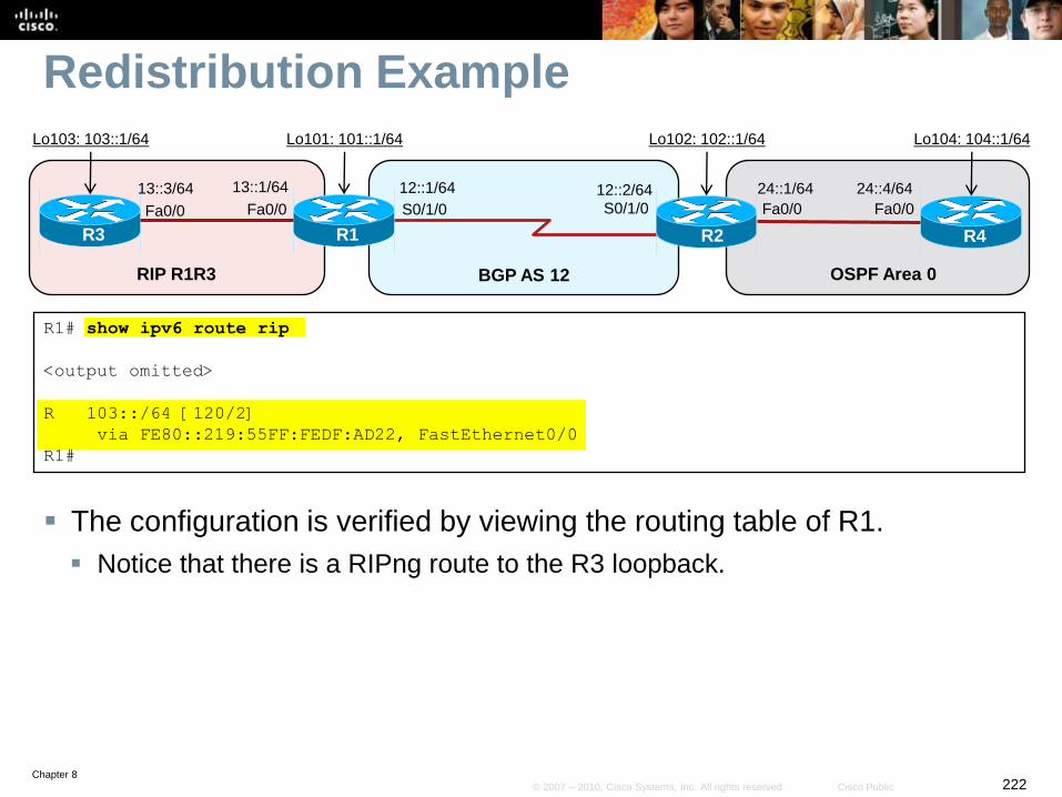
Chapter 8222© 2007 – 2010, Cisco Systems, Inc. All rights reserved. Cisco Public
Redistribution Example
The configuration is verified by viewing the routing table of R1.
Notice that there is a RIPng route to the R3 loopback.
R1# show ipv6 route rip
<output omitted>
R 103::/64 [120/2]
via FE80::219:55FF:FEDF:AD22, FastEthernet0/0
R1#
S0/1/0 S0/1/0
R1
12::2/64
R2
RIP R1R3 BGP AS 12
12::1/64
Fa0/0
13::1/64
R3
Fa0/0
13::3/64
OSPF Area 0
24::4/64
R4
Fa0/0
24::1/64
Fa0/0
Lo103: 103::1/64 Lo101: 101::1/64 Lo102: 102::1/64 Lo104: 104::1/64
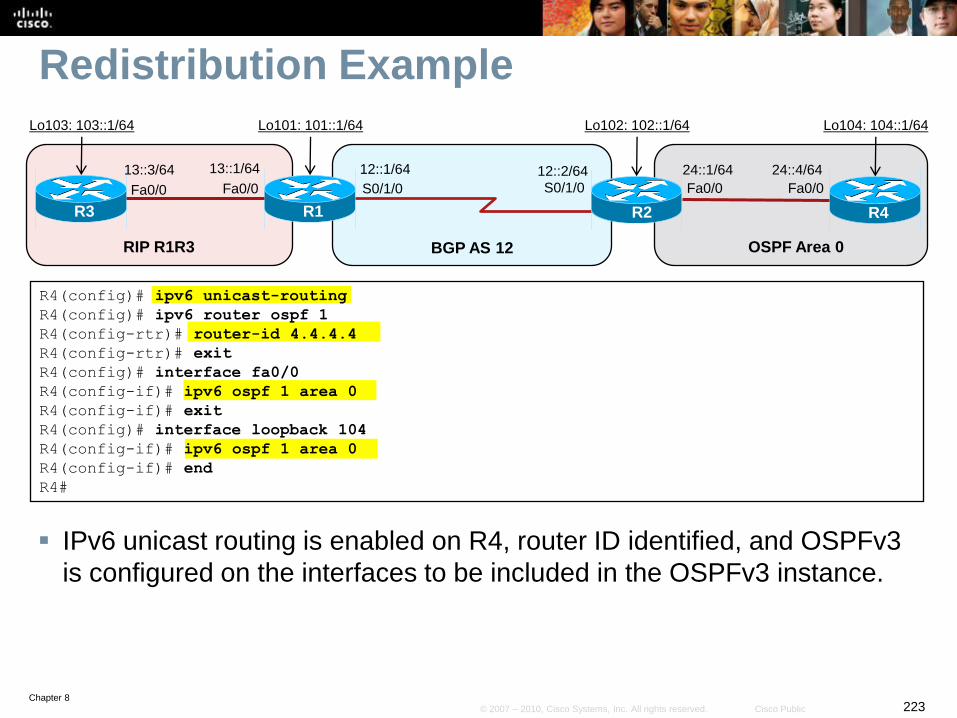
Chapter 8223© 2007 – 2010, Cisco Systems, Inc. All rights reserved. Cisco Public
Redistribution Example
IPv6 unicast routing is enabled on R4, router ID identified, and OSPFv3
is configured on the interfaces to be included in the OSPFv3 instance.
R4(config)# ipv6 unicast-routing
R4(config)# ipv6 router ospf 1
R4(config-rtr)# router-id 4.4.4.4
R4(config-rtr)# exit
R4(config)# interface fa0/0
R4(config-if)# ipv6 ospf 1 area 0
R4(config-if)# exit
R4(config)# interface loopback 104
R4(config-if)# ipv6 ospf 1 area 0
R4(config-if)# end
R4#
S0/1/0 S0/1/0
R1
12::2/64
R2
RIP R1R3 BGP AS 12
12::1/64
Fa0/0
13::1/64
R3
Fa0/0
13::3/64
OSPF Area 0
24::4/64
R4
Fa0/0
24::1/64
Fa0/0
Lo103: 103::1/64 Lo101: 101::1/64 Lo102: 102::1/64 Lo104: 104::1/64
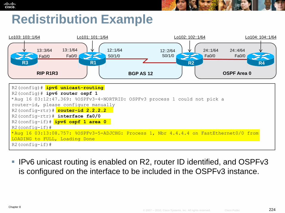
Chapter 8224© 2007 – 2010, Cisco Systems, Inc. All rights reserved. Cisco Public
Redistribution Example
IPv6 unicast routing is enabled on R2, router ID identified, and OSPFv3
is configured on the interface to be included in the OSPFv3 instance.
R2(config)# ipv6 unicast-routing
R2(config)# ipv6 router ospf 1
*Aug 16 03:12:47.369: %OSPFv3-4-NORTRID: OSPFv3 process 1 could not pick a
router-id, please configure manually
R2(config-rtr)# router-id 2.2.2.2
R2(config-rtr)# interface fa0/0
R2(config-if)# ipv6 ospf 1 area 0
R2(config-if)#
*Aug 16 03:13:08.757: %OSPFv3-5-ADJCHG: Process 1, Nbr 4.4.4.4 on FastEthernet0/0 from
LOADING to FULL, Loading Done
R2(config-if)#
S0/1/0 S0/1/0
R1
12::2/64
R2
RIP R1R3 BGP AS 12
12::1/64
Fa0/0
13::1/64
R3
Fa0/0
13::3/64
OSPF Area 0
24::4/64
R4
Fa0/0
24::1/64
Fa0/0
Lo103: 103::1/64 Lo101: 101::1/64 Lo102: 102::1/64 Lo104: 104::1/64
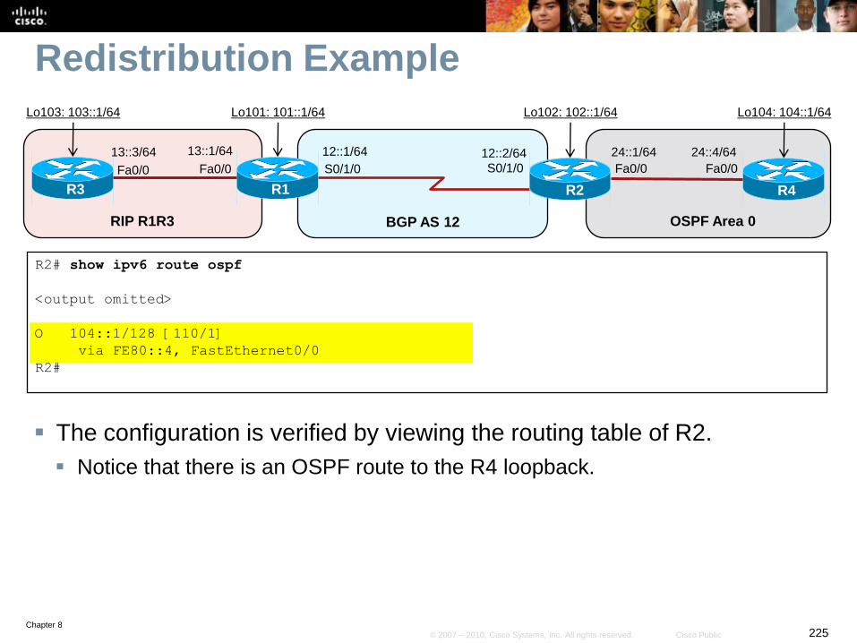
Chapter 8225© 2007 – 2010, Cisco Systems, Inc. All rights reserved. Cisco Public
Redistribution Example
The configuration is verified by viewing the routing table of R2.
Notice that there is an OSPF route to the R4 loopback.
R2# show ipv6 route ospf
<output omitted>
O 104::1/128 [110/1]
via FE80::4, FastEthernet0/0
R2#
S0/1/0 S0/1/0
R1
12::2/64
R2
RIP R1R3 BGP AS 12
12::1/64
Fa0/0
13::1/64
R3
Fa0/0
13::3/64
OSPF Area 0
24::4/64
R4
Fa0/0
24::1/64
Fa0/0
Lo103: 103::1/64 Lo101: 101::1/64 Lo102: 102::1/64 Lo104: 104::1/64
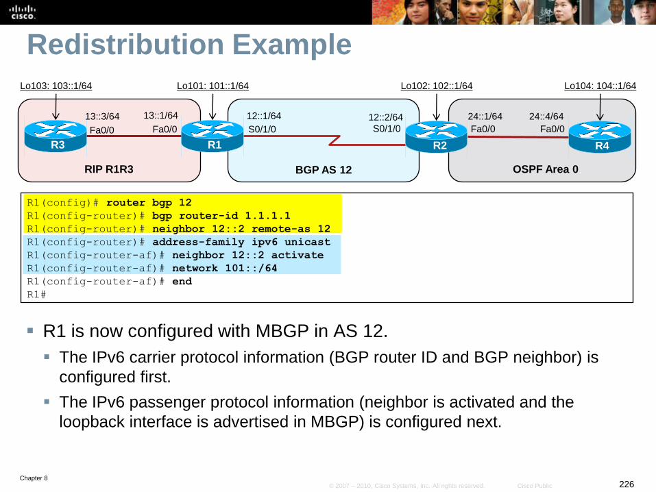
Chapter 8226© 2007 – 2010, Cisco Systems, Inc. All rights reserved. Cisco Public
Redistribution Example
R1 is now configured with MBGP in AS 12.
The IPv6 carrier protocol information (BGP router ID and BGP neighbor) is
configured first.
The IPv6 passenger protocol information (neighbor is activated and the
loopback interface is advertised in MBGP) is configured next.
R1(config)# router bgp 12
R1(config-router)# bgp router-id 1.1.1.1
R1(config-router)# neighbor 12::2 remote-as 12
R1(config-router)# address-family ipv6 unicast
R1(config-router-af)# neighbor 12::2 activate
R1(config-router-af)# network 101::/64
R1(config-router-af)# end
R1#
S0/1/0 S0/1/0
R1
12::2/64
R2
RIP R1R3 BGP AS 12
12::1/64
Fa0/0
13::1/64
R3
Fa0/0
13::3/64
OSPF Area 0
24::4/64
R4
Fa0/0
24::1/64
Fa0/0
Lo103: 103::1/64 Lo101: 101::1/64 Lo102: 102::1/64 Lo104: 104::1/64
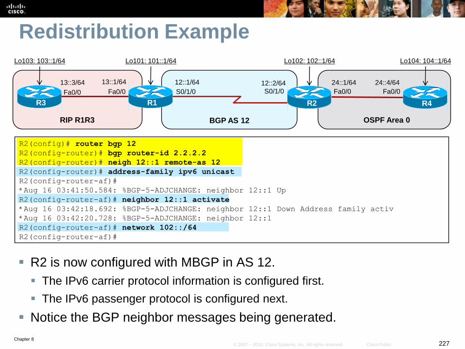
Chapter 8227© 2007 – 2010, Cisco Systems, Inc. All rights reserved. Cisco Public
Redistribution Example
R2 is now configured with MBGP in AS 12.
The IPv6 carrier protocol information is configured first.
The IPv6 passenger protocol is configured next.
Notice the BGP neighbor messages being generated.
R2(config)# router bgp 12
R2(config-router)# bgp router-id 2.2.2.2
R2(config-router)# neigh 12::1 remote-as 12
R2(config-router)# address-family ipv6 unicast
R2(config-router-af)#
*Aug 16 03:41:50.584: %BGP-5-ADJCHANGE: neighbor 12::1 Up
R2(config-router-af)# neighbor 12::1 activate
*Aug 16 03:42:18.692: %BGP-5-ADJCHANGE: neighbor 12::1 Down Address family activ
*Aug 16 03:42:20.728: %BGP-5-ADJCHANGE: neighbor 12::1
R2(config-router-af)# network 102::/64
R2(config-router-af)#
S0/1/0 S0/1/0
R1
12::2/64
R2
RIP R1R3 BGP AS 12
12::1/64
Fa0/0
13::1/64
R3
Fa0/0
13::3/64
OSPF Area 0
24::4/64
R4
Fa0/0
24::1/64
Fa0/0
Lo103: 103::1/64 Lo101: 101::1/64 Lo102: 102::1/64 Lo104: 104::1/64
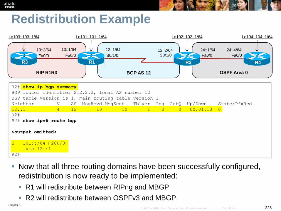
Chapter 8228© 2007 – 2010, Cisco Systems, Inc. All rights reserved. Cisco Public
Redistribution Example
Now that all three routing domains have been successfully configured,
redistribution is now ready to be implemented:
R1 will redistribute between RIPng and MBGP
R2 will redistribute between OSPFv3 and MBGP.
R2# show ip bgp summary
BGP router identifier 2.2.2.2, local AS number 12
BGP table version is 1, main routing table version 1
Neighbor V AS MsgRcvd MsgSent Tblver Inq OutQ Up/Down State/PfxRcd
12::1 4 12 10 10 1 0 0 00:01:10 0
R2#
R2# show ipv6 route bgp
<output omitted>
B 101::/64 [200/0]
via 12::1
R2#
S0/1/0 S0/1/0
R1
12::2/64
R2
RIP R1R3 BGP AS 12
12::1/64
Fa0/0
13::1/64
R3
Fa0/0
13::3/64
OSPF Area 0
24::4/64
R4
Fa0/0
24::1/64
Fa0/0
Lo103: 103::1/64 Lo101: 101::1/64 Lo102: 102::1/64 Lo104: 104::1/64
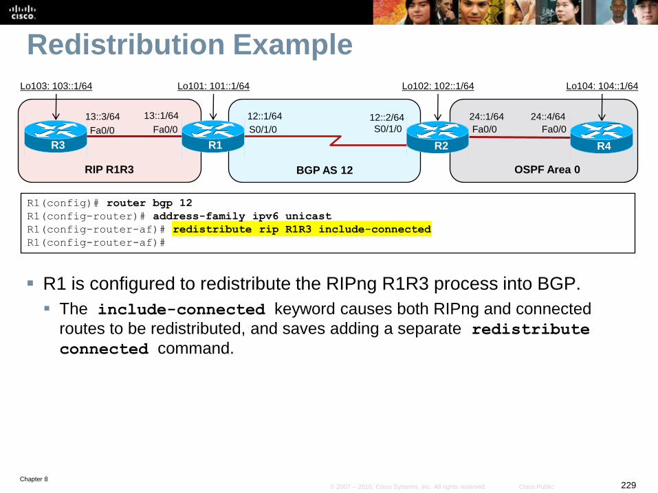
Chapter 8229© 2007 – 2010, Cisco Systems, Inc. All rights reserved. Cisco Public
Redistribution Example
R1 is configured to redistribute the RIPng R1R3 process into BGP.
The include-connected keyword causes both RIPng and connected
routes to be redistributed, and saves adding a separate redistribute
connected command.
R1(config)# router bgp 12
R1(config-router)# address-family ipv6 unicast
R1(config-router-af)# redistribute rip R1R3 include-connected
R1(config-router-af)#
S0/1/0 S0/1/0
R1
12::2/64
R2
RIP R1R3 BGP AS 12
12::1/64
Fa0/0
13::1/64
R3
Fa0/0
13::3/64
OSPF Area 0
24::4/64
R4
Fa0/0
24::1/64
Fa0/0
Lo103: 103::1/64 Lo101: 101::1/64 Lo102: 102::1/64 Lo104: 104::1/64
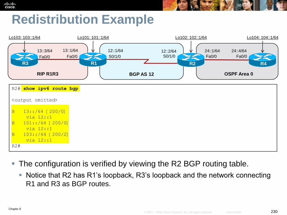
Chapter 8230© 2007 – 2010, Cisco Systems, Inc. All rights reserved. Cisco Public
Redistribution Example
The configuration is verified by viewing the R2 BGP routing table.
Notice that R2 has R1’s loopback, R3’s loopback and the network connecting
R1 and R3 as BGP routes.
R2# show ipv6 route bgp
<output omitted>
B 13::/64 [200/0]
via 12::1
B 101::/64 [200/0]
via 12::1
B 103::/64 [200/2]
via 12::1
R2#
S0/1/0 S0/1/0
R1
12::2/64
R2
RIP R1R3 BGP AS 12
12::1/64
Fa0/0
13::1/64
R3
Fa0/0
13::3/64
OSPF Area 0
24::4/64
R4
Fa0/0
24::1/64
Fa0/0
Lo103: 103::1/64 Lo101: 101::1/64 Lo102: 102::1/64 Lo104: 104::1/64
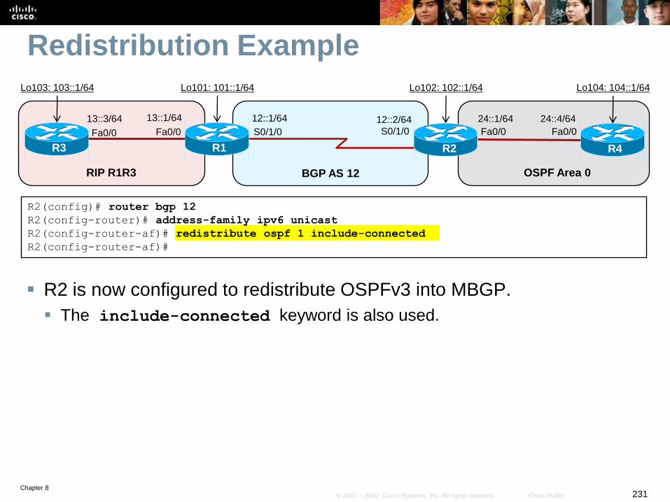
Chapter 8231© 2007 – 2010, Cisco Systems, Inc. All rights reserved. Cisco Public
Redistribution Example
R2 is now configured to redistribute OSPFv3 into MBGP.
The include-connected keyword is also used.
R2(config)# router bgp 12
R2(config-router)# address-family ipv6 unicast
R2(config-router-af)# redistribute ospf 1 include-connected
R2(config-router-af)#
S0/1/0 S0/1/0
R1
12::2/64
R2
RIP R1R3 BGP AS 12
12::1/64
Fa0/0
13::1/64
R3
Fa0/0
13::3/64
OSPF Area 0
24::4/64
R4
Fa0/0
24::1/64
Fa0/0
Lo103: 103::1/64 Lo101: 101::1/64 Lo102: 102::1/64 Lo104: 104::1/64

Chapter 8232© 2007 – 2010, Cisco Systems, Inc. All rights reserved. Cisco Public
Redistribution Example
The configuration is verified by viewing the R1 BGP routing table.
Notice that R1 has R2’s loopback, R4’s loopback and the network connecting
R2 and R4 as BGP routes.
R1# show ipv6 route bgp
<output omitted>
B 24::/64 [200/0]
via 12::2
B 102::/64 [200/0]
via 12::2
B 104::1/128 [200/1]
via 12::2
R1#
S0/1/0 S0/1/0
R1
12::2/64
R2
RIP R1R3 BGP AS 12
12::1/64
Fa0/0
13::1/64
R3
Fa0/0
13::3/64
OSPF Area 0
24::4/64
R4
Fa0/0
24::1/64
Fa0/0
Lo103: 103::1/64 Lo101: 101::1/64 Lo102: 102::1/64 Lo104: 104::1/64
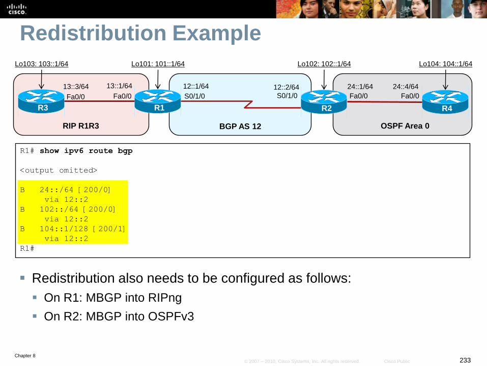
Chapter 8233© 2007 – 2010, Cisco Systems, Inc. All rights reserved. Cisco Public
Redistribution Example
Redistribution also needs to be configured as follows:
On R1: MBGP into RIPng
On R2: MBGP into OSPFv3
R1# show ipv6 route bgp
<output omitted>
B 24::/64 [200/0]
via 12::2
B 102::/64 [200/0]
via 12::2
B 104::1/128 [200/1]
via 12::2
R1#
S0/1/0 S0/1/0
R1
12::2/64
R2
RIP R1R3 BGP AS 12
12::1/64
Fa0/0
13::1/64
R3
Fa0/0
13::3/64
OSPF Area 0
24::4/64
R4
Fa0/0
24::1/64
Fa0/0
Lo103: 103::1/64 Lo101: 101::1/64 Lo102: 102::1/64 Lo104: 104::1/64
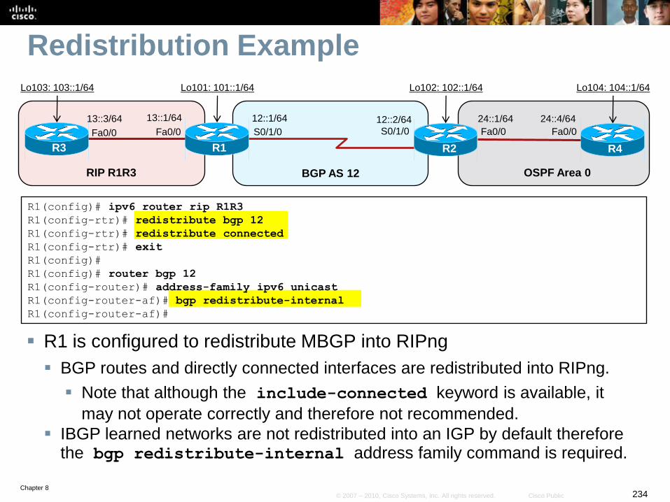
Chapter 8234© 2007 – 2010, Cisco Systems, Inc. All rights reserved. Cisco Public
Redistribution Example
R1 is configured to redistribute MBGP into RIPng
BGP routes and directly connected interfaces are redistributed into RIPng.
Note that although the include-connected keyword is available, it
may not operate correctly and therefore not recommended.
IBGP learned networks are not redistributed into an IGP by default therefore the bgp redistribute-internal address family command is required.
R1(config)# ipv6 router rip R1R3
R1(config-rtr)# redistribute bgp 12
R1(config-rtr)# redistribute connected
R1(config-rtr)# exit
R1(config)#
R1(config)# router bgp 12
R1(config-router)# address-family ipv6 unicast
R1(config-router-af)# bgp redistribute-internal
R1(config-router-af)#
S0/1/0 S0/1/0
R1
12::2/64
R2
RIP R1R3 BGP AS 12
12::1/64
Fa0/0
13::1/64
R3
Fa0/0
13::3/64
OSPF Area 0
24::4/64
R4
Fa0/0
24::1/64
Fa0/0
Lo103: 103::1/64 Lo101: 101::1/64 Lo102: 102::1/64 Lo104: 104::1/64
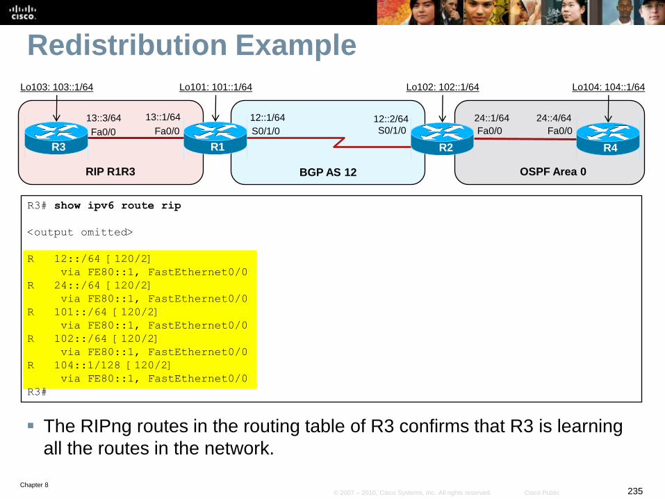
Chapter 8235© 2007 – 2010, Cisco Systems, Inc. All rights reserved. Cisco Public
Redistribution Example
The RIPng routes in the routing table of R3 confirms that R3 is learning
all the routes in the network.
R3# show ipv6 route rip
<output omitted>
R 12::/64 [120/2]
via FE80::1, FastEthernet0/0
R 24::/64 [120/2]
via FE80::1, FastEthernet0/0
R 101::/64 [120/2]
via FE80::1, FastEthernet0/0
R 102::/64 [120/2]
via FE80::1, FastEthernet0/0
R 104::1/128 [120/2]
via FE80::1, FastEthernet0/0
R3#
S0/1/0 S0/1/0
R1
12::2/64
R2
RIP R1R3 BGP AS 12
12::1/64
Fa0/0
13::1/64
R3
Fa0/0
13::3/64
OSPF Area 0
24::4/64
R4
Fa0/0
24::1/64
Fa0/0
Lo103: 103::1/64 Lo101: 101::1/64 Lo102: 102::1/64 Lo104: 104::1/64
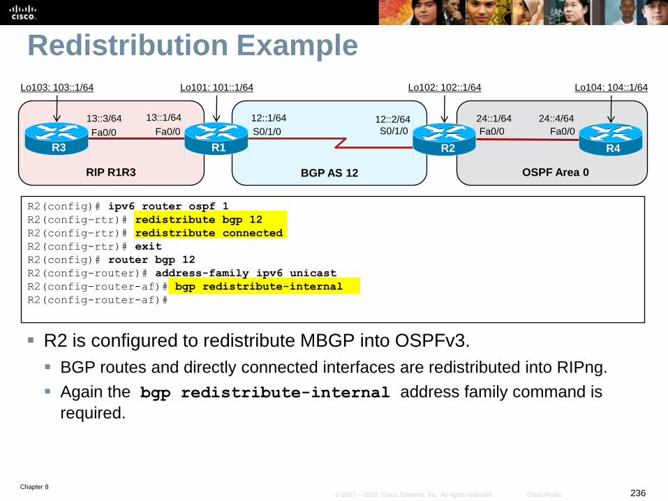
Chapter 8236© 2007 – 2010, Cisco Systems, Inc. All rights reserved. Cisco Public
Redistribution Example
R2 is configured to redistribute MBGP into OSPFv3.
BGP routes and directly connected interfaces are redistributed into RIPng.
Again the bgp redistribute-internal address family command is
required.
R2(config)# ipv6 router ospf 1
R2(config-rtr)# redistribute bgp 12
R2(config-rtr)# redistribute connected
R2(config-rtr)# exit
R2(config)# router bgp 12
R2(config-router)# address-family ipv6 unicast
R2(config-router-af)# bgp redistribute-internal
R2(config-router-af)#
S0/1/0 S0/1/0
R1
12::2/64
R2
RIP R1R3 BGP AS 12
12::1/64
Fa0/0
13::1/64
R3
Fa0/0
13::3/64
OSPF Area 0
24::4/64
R4
Fa0/0
24::1/64
Fa0/0
Lo103: 103::1/64 Lo101: 101::1/64 Lo102: 102::1/64 Lo104: 104::1/64
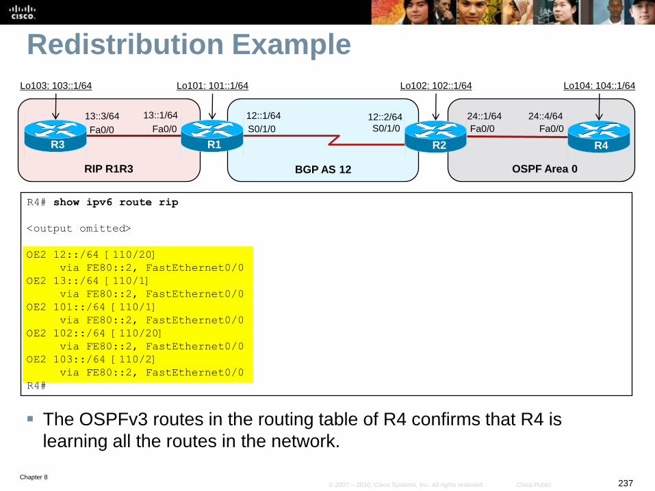
Chapter 8237© 2007 – 2010, Cisco Systems, Inc. All rights reserved. Cisco Public
Redistribution Example
The OSPFv3 routes in the routing table of R4 confirms that R4 is
learning all the routes in the network.
R4# show ipv6 route rip
<output omitted>
OE2 12::/64 [110/20]
via FE80::2, FastEthernet0/0
OE2 13::/64 [110/1]
via FE80::2, FastEthernet0/0
OE2 101::/64 [110/1]
via FE80::2, FastEthernet0/0
OE2 102::/64 [110/20]
via FE80::2, FastEthernet0/0
OE2 103::/64 [110/2]
via FE80::2, FastEthernet0/0
R4#
S0/1/0 S0/1/0
R1
12::2/64
R2
RIP R1R3 BGP AS 12
12::1/64
Fa0/0
13::1/64
R3
Fa0/0
13::3/64
OSPF Area 0
24::4/64
R4
Fa0/0
24::1/64
Fa0/0
Lo103: 103::1/64 Lo101: 101::1/64 Lo102: 102::1/64 Lo104: 104::1/64

Chapter 8238© 2007 – 2010, Cisco Systems, Inc. All rights reserved. Cisco Public
Transitioning IPv4 to IPv6
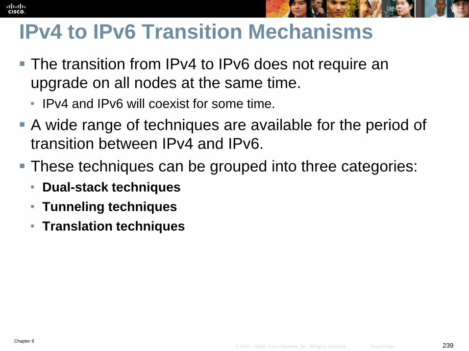
Chapter 8239© 2007 – 2010, Cisco Systems, Inc. All rights reserved. Cisco Public
IPv4 to IPv6 Transition Mechanisms
The transition from IPv4 to IPv6 does not require an
upgrade on all nodes at the same time.
• IPv4 and IPv6 will coexist for some time.
A wide range of techniques are available for the period of
transition between IPv4 and IPv6.
These techniques can be grouped into three categories:
• Dual-stack techniques
• Tunneling techniques
• Translation techniques
Chapter 8240© 2007 – 2010, Cisco Systems, Inc. All rights reserved. Cisco Public
Dual-Stack Techniques
Hosts and network devices run both IPv4 and IPv6 at the
same time.
• This technique is useful as a temporary transition, but it adds
overhead and uses many resources.
Cisco IOS Software is IPv6 ready.
• As soon as IPv4 and IPv6 configurations are complete, the interface is
dual stacked and it forwards both IPv4 and IPv6 traffic.
Drawback of dual stacking includes:
• The additional resources required to keep and process dual routing
tables, routing protocol topology tables, etc.
• The higher administrative overhead, troubleshooting, and monitoring,
is more complex.
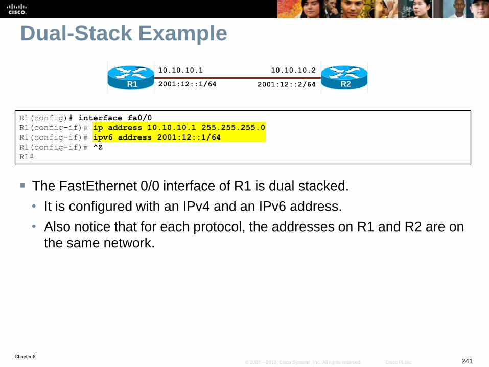
Chapter 8241© 2007 – 2010, Cisco Systems, Inc. All rights reserved. Cisco Public
Dual-Stack Example
The FastEthernet 0/0 interface of R1 is dual stacked.
• It is configured with an IPv4 and an IPv6 address.
• Also notice that for each protocol, the addresses on R1 and R2 are on
the same network.
R2
10.10.10.1
R1
R1(config)# interface fa0/0
R1(config-if)# ip address 10.10.10.1 255.255.255.0
R1(config-if)# ipv6 address 2001:12::1/64
R1(config-if)# ^Z
R1#
10.10.10.2
2001:12::1/64 2001:12::2/64
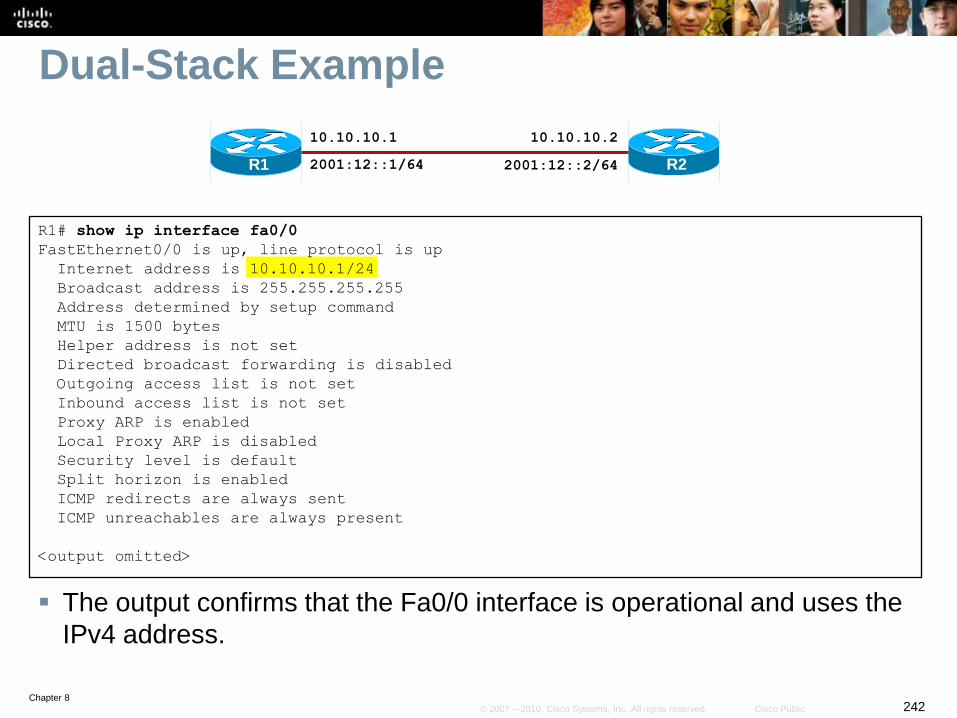
Chapter 8242© 2007 – 2010, Cisco Systems, Inc. All rights reserved. Cisco Public
Dual-Stack Example
The output confirms that the Fa0/0 interface is operational and uses the
IPv4 address.
R1# show ip interface fa0/0
FastEthernet0/0 is up, line protocol is up
Internet address is 10.10.10.1/24
Broadcast address is 255.255.255.255
Address determined by setup command
MTU is 1500 bytes
Helper address is not set
Directed broadcast forwarding is disabled
Outgoing access list is not set
Inbound access list is not set
Proxy ARP is enabled
Local Proxy ARP is disabled
Security level is default
Split horizon is enabled
ICMP redirects are always sent
ICMP unreachables are always present
<output omitted>
R2
10.10.10.1
R1
10.10.10.2
2001:12::1/64 2001:12::2/64
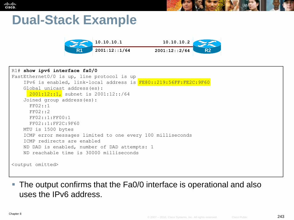
Chapter 8243© 2007 – 2010, Cisco Systems, Inc. All rights reserved. Cisco Public
Dual-Stack Example
The output confirms that the Fa0/0 interface is operational and also
uses the IPv6 address.
R1# show ipv6 interface fa0/0
FastEthernet0/0 is up, line protocol is up
IPv6 is enabled, link-local address is FE80::219:56FF:FE2C:9F60
Global unicast address(es):
2001:12::1, subnet is 2001:12::/64
Joined group address(es):
FF02::1
FF02::2
FF02::1:FF00:1
FF02::1:FF2C:9F60
MTU is 1500 bytes
ICMP error messages limited to one every 100 milliseconds
ICMP redirects are enabled
ND DAD is enabled, number of DAD attempts: 1
ND reachable time is 30000 milliseconds
<output omitted>
R2
10.10.10.1
R1
10.10.10.2
2001:12::1/64 2001:12::2/64
Chapter 8244© 2007 – 2010, Cisco Systems, Inc. All rights reserved. Cisco Public
Tunneling Techniques
Isolated IPv6 networks are connected over an IPv4
infrastructure using tunnels.
The edge devices are the only ones that need to be dual-
stacked.
Scalability may be an issue if many tunnels need to be
created.
• Tunnels can be either manually or automatically configured,
depending on the scale required and administrative overhead
tolerated.
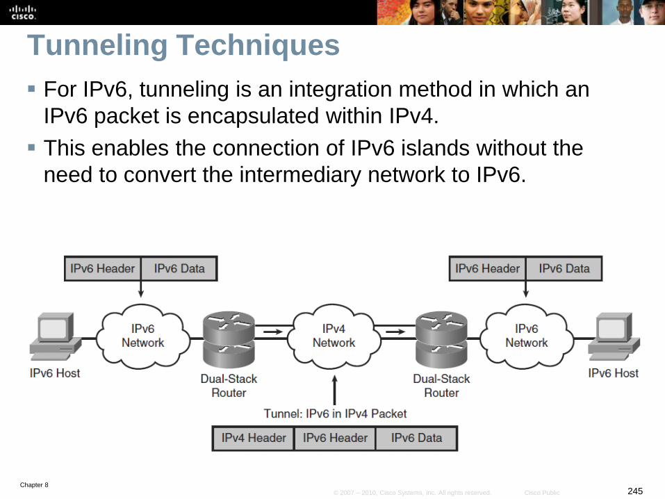
Chapter 8245© 2007 – 2010, Cisco Systems, Inc. All rights reserved. Cisco Public
Tunneling Techniques
For IPv6, tunneling is an integration method in which an
IPv6 packet is encapsulated within IPv4.
This enables the connection of IPv6 islands without the
need to convert the intermediary network to IPv6.
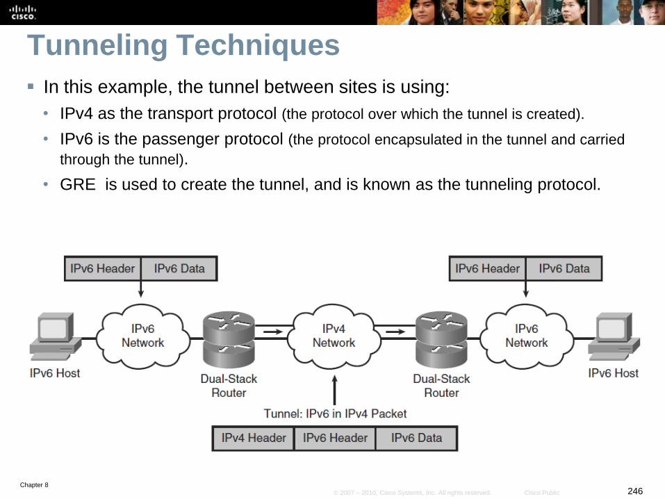
Chapter 8246© 2007 – 2010, Cisco Systems, Inc. All rights reserved. Cisco Public
Tunneling Techniques
In this example, the tunnel between sites is using:
• IPv4 as the transport protocol (the protocol over which the tunnel is created).
• IPv6 is the passenger protocol (the protocol encapsulated in the tunnel and carried
through the tunnel).
• GRE is used to create the tunnel, and is known as the tunneling protocol.
Chapter 8247© 2007 – 2010, Cisco Systems, Inc. All rights reserved. Cisco Public
Translation Techniques
Dual stack and tunneling techniques manage the
interconnection of IPv6 domains.
NAT-PT is an extension of NAT techniques and it provides
protocol translation services for legacy equipment that
cannot be upgraded to IPv6 and for some deployment
scenarios.
A router converts IPv6 packets into IPv4 packets and vise
versa, allowing IPv6-only devices to communicate with
IPv4-only devices.
• Scalability may again be an issue because of the resources required
on the translator device.
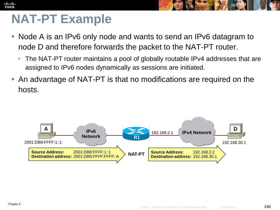
Chapter 8248© 2007 – 2010, Cisco Systems, Inc. All rights reserved. Cisco Public
NAT-PT Example
Node A is an IPv6 only node and wants to send an IPv6 datagram to
node D and therefore forwards the packet to the NAT-PT router.
• The NAT-PT router maintains a pool of globally routable IPv4 addresses that are
assigned to IPv6 nodes dynamically as sessions are initiated.
An advantage of NAT-PT is that no modifications are required on the
hosts.
A
R1
D
NAT-PT
IPv6Network
192.168.2.1 IPv4 Network
2001:DB8:FFFF:1::1 192.168.30.1
Source Address: 2001:DB8:FFFF:1::1 Destination address: 2001:DB8:FFFF:FFFF::A
Source Address: 192.168.2.2Destination address: 192.168.30.1

Chapter 8249© 2007 – 2010, Cisco Systems, Inc. All rights reserved. Cisco Public
Tunneling IPv6 Traffic
Chapter 8250© 2007 – 2010, Cisco Systems, Inc. All rights reserved. Cisco Public
Types of Tunnels
Tunnels can be created manually using:
• Manual IPv6 tunnels
• GRE IPv6 tunnels
Tunnels can also be created automatically using:
• IPv4-Compatible IPv6 Tunnels (now deprecated)
• 6to4 tunnels
• ISATAP Tunnels
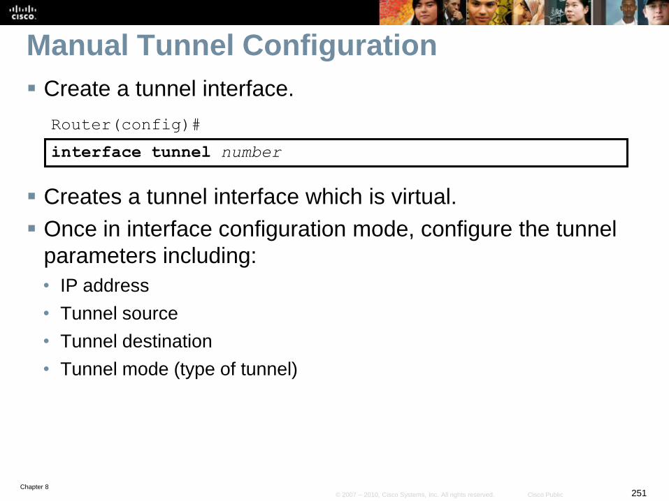
Chapter 8251© 2007 – 2010, Cisco Systems, Inc. All rights reserved. Cisco Public
Manual Tunnel Configuration
Create a tunnel interface.
Router(config)#
interface tunnel number
Creates a tunnel interface which is virtual.
Once in interface configuration mode, configure the tunnel
parameters including:
• IP address
• Tunnel source
• Tunnel destination
• Tunnel mode (type of tunnel)
Chapter 8252© 2007 – 2010, Cisco Systems, Inc. All rights reserved. Cisco Public
Tunnel Commands
The tunnel source interface-type interface-
number interface configuration command sets the source
address for a tunnel interface as the address of the
specified interface.
The tunnel destination ip-address interface
configuration command specifies the destination address
for a tunnel interface.
• In this case the ip-address is an IPv4 address
The tunnel mode ipv6ip interface configuration
command sets the encapsulation mode for the tunnel
interface to use IPv6 as the passenger protocol, and IPv4
as both the encapsulation and transport protocol.
Chapter 8253© 2007 – 2010, Cisco Systems, Inc. All rights reserved. Cisco Public
Tunnel Commands
Use the following commands to troubleshoot a tunnel
configuration:
• The debug tunnel EXEC command enables the display of a
tunnel encapsulation and decapsulation process.
• The debug ip packet detail EXEC command enables the
display of details about IP packets traversing the router.
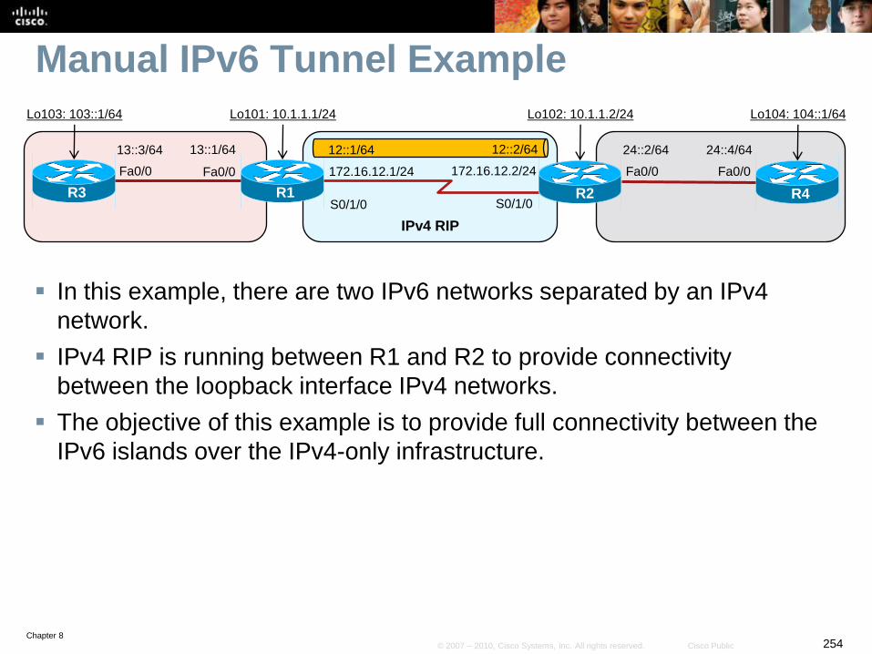
Chapter 8254© 2007 – 2010, Cisco Systems, Inc. All rights reserved. Cisco Public
Manual IPv6 Tunnel Example
In this example, there are two IPv6 networks separated by an IPv4
network.
IPv4 RIP is running between R1 and R2 to provide connectivity
between the loopback interface IPv4 networks.
The objective of this example is to provide full connectivity between the
IPv6 islands over the IPv4-only infrastructure.
S0/1/0 S0/1/0R1 R2
IPv4 RIP
Fa0/0
13::1/64
R3
Fa0/0
13::3/64 24::4/64
R4
Fa0/0
24::2/64
Fa0/0
Lo103: 103::1/64 Lo101: 10.1.1.1/24 Lo102: 10.1.1.2/24 Lo104: 104::1/64
12::2/6412::1/64
172.16.12.1/24 172.16.12.2/24
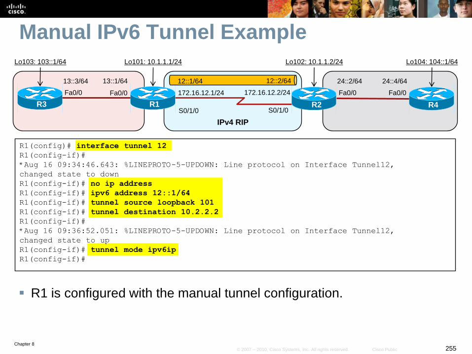
Chapter 8255© 2007 – 2010, Cisco Systems, Inc. All rights reserved. Cisco Public
Manual IPv6 Tunnel Example
R1 is configured with the manual tunnel configuration.
R1(config)# interface tunnel 12
R1(config-if)#
*Aug 16 09:34:46.643: %LINEPROTO-5-UPDOWN: Line protocol on Interface Tunnel12,
changed state to down
R1(config-if)# no ip address
R1(config-if)# ipv6 address 12::1/64
R1(config-if)# tunnel source loopback 101
R1(config-if)# tunnel destination 10.2.2.2
R1(config-if)#
*Aug 16 09:36:52.051: %LINEPROTO-5-UPDOWN: Line protocol on Interface Tunnel12,
changed state to up
R1(config-if)# tunnel mode ipv6ip
R1(config-if)#
S0/1/0 S0/1/0R1 R2
IPv4 RIP
Fa0/0
13::1/64
R3
Fa0/0
13::3/64 24::4/64
R4
Fa0/0
24::2/64
Fa0/0
Lo103: 103::1/64 Lo101: 10.1.1.1/24 Lo102: 10.1.1.2/24 Lo104: 104::1/64
12::2/6412::1/64
172.16.12.1/24 172.16.12.2/24

Chapter 8256© 2007 – 2010, Cisco Systems, Inc. All rights reserved. Cisco Public
Manual IPv6 Tunnel Example
R2 is now configured with the manual tunnel configuration.
R2(config)# interface tunnel 12
R2(config-if)#
*Aug 16 09:38:47.532: %LINEPROTO-5-UPDOWN: Line protocol on Interface Tunnel12,
changed state to down
R2(config-if)# no ip address
R2(config-if)# ipv6 address 12::2/64
R2(config-if)# tunnel source loopback 102
R2(config-if)# tunnel destination 10.1.1.1
R2(config-if)#
*Aug 16 09:39:24.056: %LINEPROTO-5-UPDOWN: Line protocol on Interface Tunnel12,
changed state to up
R2(config-if)# tunnel mode ipv6ip
R2(config-if)#
S0/1/0 S0/1/0R1 R2
IPv4 RIP
Fa0/0
13::1/64
R3
Fa0/0
13::3/64 24::4/64
R4
Fa0/0
24::2/64
Fa0/0
Lo103: 103::1/64 Lo101: 10.1.1.1/24 Lo102: 10.1.1.2/24 Lo104: 104::1/64
12::2/6412::1/64
172.16.12.1/24 172.16.12.2/24
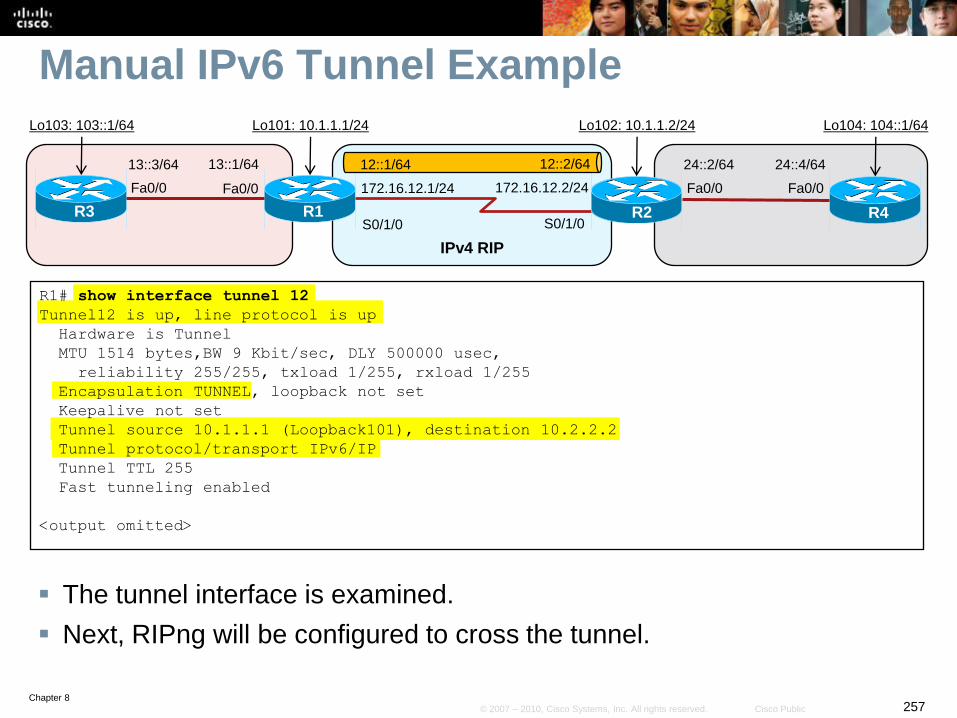
Chapter 8257© 2007 – 2010, Cisco Systems, Inc. All rights reserved. Cisco Public
Manual IPv6 Tunnel Example
The tunnel interface is examined.
Next, RIPng will be configured to cross the tunnel.
R1# show interface tunnel 12
Tunnel12 is up, line protocol is up
Hardware is Tunnel
MTU 1514 bytes,BW 9 Kbit/sec, DLY 500000 usec,
reliability 255/255, txload 1/255, rxload 1/255
Encapsulation TUNNEL, loopback not set
Keepalive not set
Tunnel source 10.1.1.1 (Loopback101), destination 10.2.2.2
Tunnel protocol/transport IPv6/IP
Tunnel TTL 255
Fast tunneling enabled
<output omitted>
S0/1/0 S0/1/0R1 R2
IPv4 RIP
Fa0/0
13::1/64
R3
Fa0/0
13::3/64 24::4/64
R4
Fa0/0
24::2/64
Fa0/0
Lo103: 103::1/64 Lo101: 10.1.1.1/24 Lo102: 10.1.1.2/24 Lo104: 104::1/64
12::2/6412::1/64
172.16.12.1/24 172.16.12.2/24
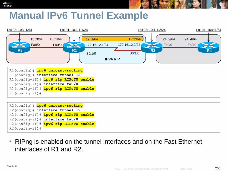
Chapter 8258© 2007 – 2010, Cisco Systems, Inc. All rights reserved. Cisco Public
Manual IPv6 Tunnel Example
RIPng is enabled on the tunnel interfaces and on the Fast Ethernet
interfaces of R1 and R2.
R1(config)# ipv6 unicast-routing
R1(config)# interface tunnel 12
R1(config-if)# ipv6 rip RIPoTU enable
R1(config-if)# interface fa0/0
R1(config-if)# ipv6 rip RIPoTU enable
R1(config-if)#
R2(config)# ipv6 unicast-routing
R2(config)# interface tunnel 12
R2(config-if)# ipv6 rip RIPoTU enable
R2(config-if)# interface fa0/0
R2(config-if)# ipv6 rip RIPoTU enable
R2(config-if)#
S0/1/0 S0/1/0R1 R2
IPv4 RIP
Fa0/0
13::1/64
R3
Fa0/0
13::3/64 24::4/64
R4
Fa0/0
24::2/64
Fa0/0
Lo103: 103::1/64 Lo101: 10.1.1.1/24 Lo102: 10.1.1.2/24 Lo104: 104::1/64
12::2/6412::1/64
172.16.12.1/24 172.16.12.2/24
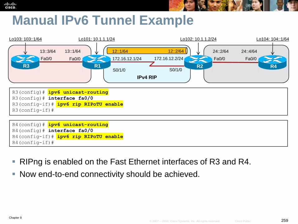
Chapter 8259© 2007 – 2010, Cisco Systems, Inc. All rights reserved. Cisco Public
Manual IPv6 Tunnel Example
RIPng is enabled on the Fast Ethernet interfaces of R3 and R4.
Now end-to-end connectivity should be achieved.
R3(config)# ipv6 unicast-routing
R3(config)# interface fa0/0
R3(config-if)# ipv6 rip RIPoTU enable
R3(config-if)#
R4(config)# ipv6 unicast-routing
R4(config)# interface fa0/0
R4(config-if)# ipv6 rip RIPoTU enable
R4(config-if)#
S0/1/0 S0/1/0R1 R2
IPv4 RIP
Fa0/0
13::1/64
R3
Fa0/0
13::3/64 24::4/64
R4
Fa0/0
24::2/64
Fa0/0
Lo103: 103::1/64 Lo101: 10.1.1.1/24 Lo102: 10.1.1.2/24 Lo104: 104::1/64
12::2/6412::1/64
172.16.12.1/24 172.16.12.2/24
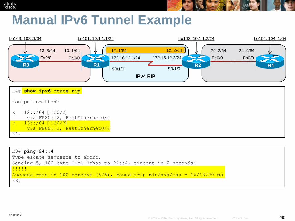
Chapter 8260© 2007 – 2010, Cisco Systems, Inc. All rights reserved. Cisco Public
Manual IPv6 Tunnel Example
R4# show ipv6 route rip
<output omitted>
R 12::/64 [120/2]
via FE80::2, FastEthernet0/0
R 13::/64 [120/3]
via FE80::2, FastEthernet0/0
R4#
R3# ping 24::4
Type escape sequence to abort.
Sending 5, 100-byte ICMP Echos to 24::4, timeout is 2 seconds:
!!!!!
Success rate is 100 percent (5/5), round-trip min/avg/max = 16/18/20 ms
R3#
S0/1/0 S0/1/0R1 R2
IPv4 RIP
Fa0/0
13::1/64
R3
Fa0/0
13::3/64 24::4/64
R4
Fa0/0
24::2/64
Fa0/0
Lo103: 103::1/64 Lo101: 10.1.1.1/24 Lo102: 10.1.1.2/24 Lo104: 104::1/64
12::2/6412::1/64
172.16.12.1/24 172.16.12.2/24
Chapter 8261© 2007 – 2010, Cisco Systems, Inc. All rights reserved. Cisco Public
Manual IPv6 Tunnel Summary
Manual tunnels are simple to configure, and are therefore
useful for a small number of sites.
However, for large networks manual tunnels are not
scalable, from both a configuration and management
perspective.
The edge routers on which the tunnels terminate need to be
dual stacked, and therefore must be capable of running
both protocols and have the capacity to do so.
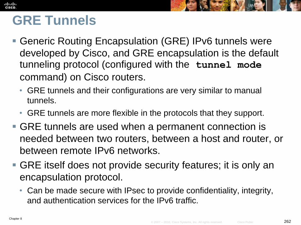
Chapter 8262© 2007 – 2010, Cisco Systems, Inc. All rights reserved. Cisco Public
GRE Tunnels
Generic Routing Encapsulation (GRE) IPv6 tunnels were
developed by Cisco, and GRE encapsulation is the default tunneling protocol (configured with the tunnel mode
command) on Cisco routers.
• GRE tunnels and their configurations are very similar to manual
tunnels.
• GRE tunnels are more flexible in the protocols that they support.
GRE tunnels are used when a permanent connection is
needed between two routers, between a host and router, or
between remote IPv6 networks.
GRE itself does not provide security features; it is only an
encapsulation protocol.
• Can be made secure with IPsec to provide confidentiality, integrity,
and authentication services for the IPv6 traffic.
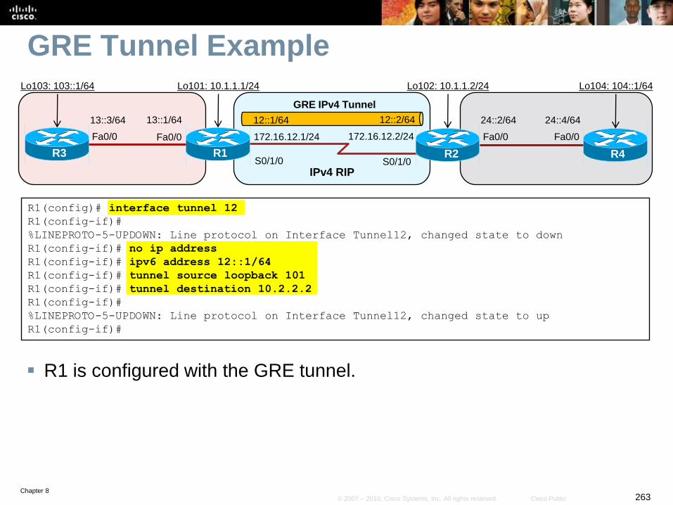
Chapter 8263© 2007 – 2010, Cisco Systems, Inc. All rights reserved. Cisco Public
GRE Tunnel Example
R1 is configured with the GRE tunnel.
R1(config)# interface tunnel 12
R1(config-if)#
%LINEPROTO-5-UPDOWN: Line protocol on Interface Tunnel12, changed state to down
R1(config-if)# no ip address
R1(config-if)# ipv6 address 12::1/64
R1(config-if)# tunnel source loopback 101
R1(config-if)# tunnel destination 10.2.2.2
R1(config-if)#
%LINEPROTO-5-UPDOWN: Line protocol on Interface Tunnel12, changed state to up
R1(config-if)#
S0/1/0 S0/1/0R1 R2
IPv4 RIP
Fa0/0
13::1/64
R3
Fa0/0
13::3/64 24::4/64
R4
Fa0/0
24::2/64
Fa0/0
Lo103: 103::1/64 Lo101: 10.1.1.1/24 Lo102: 10.1.1.2/24 Lo104: 104::1/64
12::2/6412::1/64
172.16.12.1/24 172.16.12.2/24
GRE IPv4 Tunnel
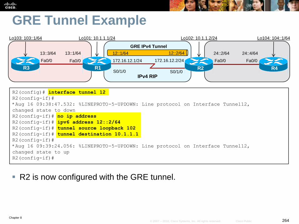
Chapter 8264© 2007 – 2010, Cisco Systems, Inc. All rights reserved. Cisco Public
GRE Tunnel Example
R2 is now configured with the GRE tunnel.
R2(config)# interface tunnel 12
R2(config-if)#
*Aug 16 09:38:47.532: %LINEPROTO-5-UPDOWN: Line protocol on Interface Tunnel12,
changed state to down
R2(config-if)# no ip address
R2(config-if)# ipv6 address 12::2/64
R2(config-if)# tunnel source loopback 102
R2(config-if)# tunnel destination 10.1.1.1
R2(config-if)#
*Aug 16 09:39:24.056: %LINEPROTO-5-UPDOWN: Line protocol on Interface Tunnel12,
changed state to up
R2(config-if)#
S0/1/0 S0/1/0R1 R2
IPv4 RIP
Fa0/0
13::1/64
R3
Fa0/0
13::3/64 24::4/64
R4
Fa0/0
24::2/64
Fa0/0
Lo103: 103::1/64 Lo101: 10.1.1.1/24 Lo102: 10.1.1.2/24 Lo104: 104::1/64
12::2/6412::1/64
172.16.12.1/24 172.16.12.2/24
GRE IPv4 Tunnel
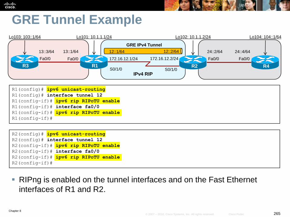
Chapter 8265© 2007 – 2010, Cisco Systems, Inc. All rights reserved. Cisco Public
GRE Tunnel Example
RIPng is enabled on the tunnel interfaces and on the Fast Ethernet
interfaces of R1 and R2.
R1(config)# ipv6 unicast-routing
R1(config)# interface tunnel 12
R1(config-if)# ipv6 rip RIPoTU enable
R1(config-if)# interface fa0/0
R1(config-if)# ipv6 rip RIPoTU enable
R1(config-if)#
R2(config)# ipv6 unicast-routing
R2(config)# interface tunnel 12
R2(config-if)# ipv6 rip RIPoTU enable
R2(config-if)# interface fa0/0
R2(config-if)# ipv6 rip RIPoTU enable
R2(config-if)#
S0/1/0 S0/1/0R1 R2
IPv4 RIP
Fa0/0
13::1/64
R3
Fa0/0
13::3/64 24::4/64
R4
Fa0/0
24::2/64
Fa0/0
Lo103: 103::1/64 Lo101: 10.1.1.1/24 Lo102: 10.1.1.2/24 Lo104: 104::1/64
12::2/6412::1/64
172.16.12.1/24 172.16.12.2/24
GRE IPv4 Tunnel
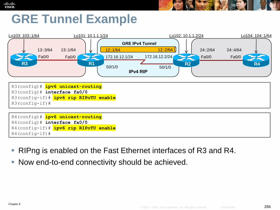
Chapter 8266© 2007 – 2010, Cisco Systems, Inc. All rights reserved. Cisco Public
GRE Tunnel Example
RIPng is enabled on the Fast Ethernet interfaces of R3 and R4.
Now end-to-end connectivity should be achieved.
R3(config)# ipv6 unicast-routing
R3(config)# interface fa0/0
R3(config-if)# ipv6 rip RIPoTU enable
R3(config-if)#
R4(config)# ipv6 unicast-routing
R4(config)# interface fa0/0
R4(config-if)# ipv6 rip RIPoTU enable
R4(config-if)#
S0/1/0 S0/1/0R1 R2
IPv4 RIP
Fa0/0
13::1/64
R3
Fa0/0
13::3/64 24::4/64
R4
Fa0/0
24::2/64
Fa0/0
Lo103: 103::1/64 Lo101: 10.1.1.1/24 Lo102: 10.1.1.2/24 Lo104: 104::1/64
12::2/6412::1/64
172.16.12.1/24 172.16.12.2/24
GRE IPv4 Tunnel
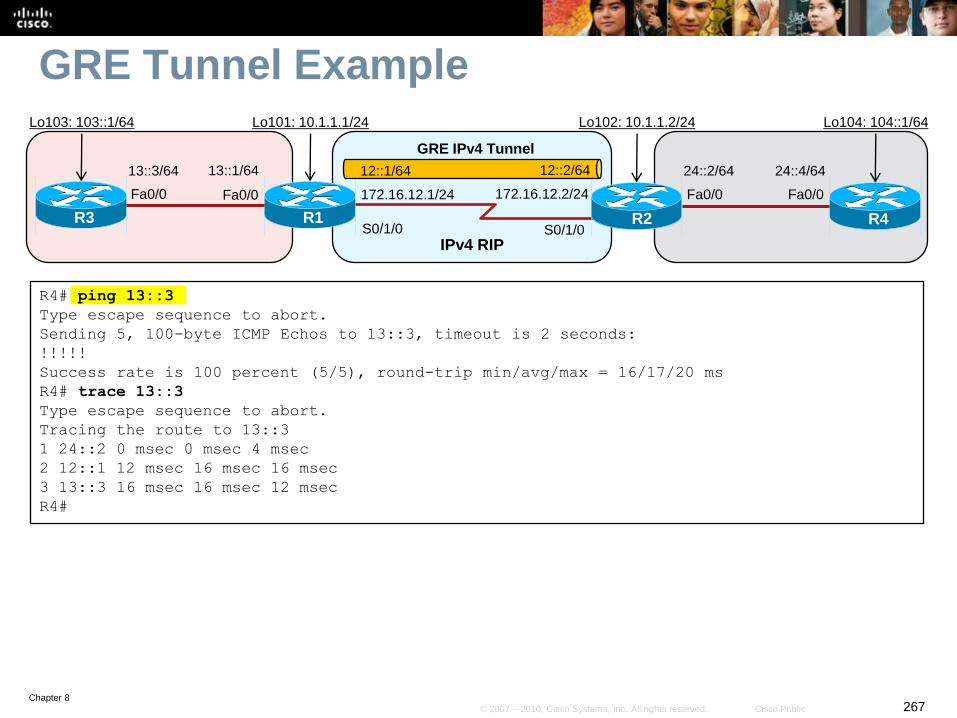
Chapter 8267© 2007 – 2010, Cisco Systems, Inc. All rights reserved. Cisco Public
GRE Tunnel Example
R4# ping 13::3
Type escape sequence to abort.
Sending 5, 100-byte ICMP Echos to 13::3, timeout is 2 seconds:
!!!!!
Success rate is 100 percent (5/5), round-trip min/avg/max = 16/17/20 ms
R4# trace 13::3
Type escape sequence to abort.
Tracing the route to 13::3
1 24::2 0 msec 0 msec 4 msec
2 12::1 12 msec 16 msec 16 msec
3 13::3 16 msec 16 msec 12 msec
R4#
S0/1/0 S0/1/0R1 R2
IPv4 RIP
Fa0/0
13::1/64
R3
Fa0/0
13::3/64 24::4/64
R4
Fa0/0
24::2/64
Fa0/0
Lo103: 103::1/64 Lo101: 10.1.1.1/24 Lo102: 10.1.1.2/24 Lo104: 104::1/64
12::2/6412::1/64
172.16.12.1/24 172.16.12.2/24
GRE IPv4 Tunnel
Chapter 8268© 2007 – 2010, Cisco Systems, Inc. All rights reserved. Cisco Public
6to4 Tunnels
6to4 tunnels, also known as a 6-to-4 tunnel, is an automatic
tunneling method.
6to4 tunnels are point-to-multipoint, rather than the point-to-
point tunnels.
The 6to4 tunnels are built automatically by the edge routers,
based on embedded IPv4 address within the IPv6
addresses of the tunnel interfaces on the edge routers.
6to4 tunnels enable the fast deployment of IPv6 in a
corporate network without the need for public IPv6
addresses from ISPs or registries.
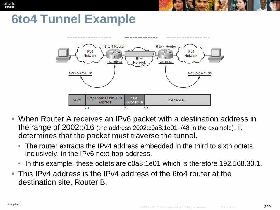
Chapter 8269© 2007 – 2010, Cisco Systems, Inc. All rights reserved. Cisco Public
6to4 Tunnel Example
When Router A receives an IPv6 packet with a destination address in the range of 2002::/16 (the address 2002:c0a8:1e01::/48 in the example), it determines that the packet must traverse the tunnel.
• The router extracts the IPv4 address embedded in the third to sixth octets, inclusively, in the IPv6 next-hop address.
• In this example, these octets are c0a8:1e01 which is therefore 192.168.30.1.
This IPv4 address is the IPv4 address of the 6to4 router at the destination site, Router B.
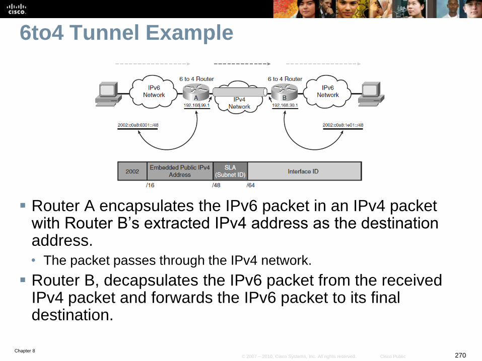
Chapter 8270© 2007 – 2010, Cisco Systems, Inc. All rights reserved. Cisco Public
6to4 Tunnel Example
Router A encapsulates the IPv6 packet in an IPv4 packet with Router B’s extracted IPv4 address as the destination address.
• The packet passes through the IPv4 network.
Router B, decapsulates the IPv6 packet from the received IPv4 packet and forwards the IPv6 packet to its final destination.
Chapter 8271© 2007 – 2010, Cisco Systems, Inc. All rights reserved. Cisco Public
6to4 Limitations
Only static routes or BGP are supported.
• This is because the other routing protocols use link-local addresses to
form adjacencies and exchange updates and these do not conform to
the address requirements for 6to4 tunnels.
NAT cannot be used along the IPv4 path of the tunnel,
again because of the 6to4 address requirements.
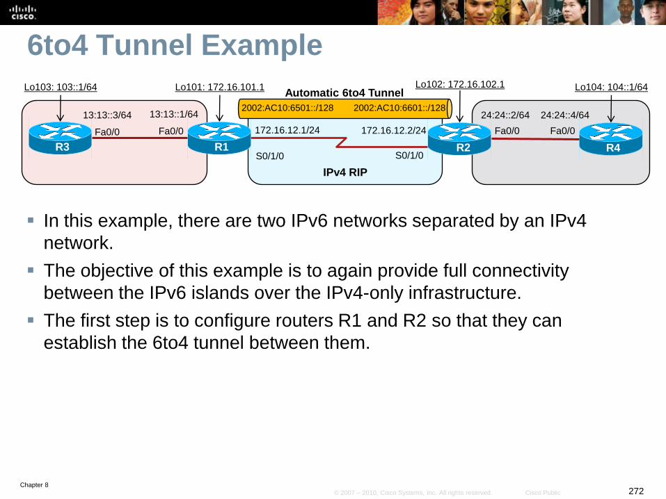
Chapter 8272© 2007 – 2010, Cisco Systems, Inc. All rights reserved. Cisco Public
6to4 Tunnel Example
In this example, there are two IPv6 networks separated by an IPv4
network.
The objective of this example is to again provide full connectivity
between the IPv6 islands over the IPv4-only infrastructure.
The first step is to configure routers R1 and R2 so that they can
establish the 6to4 tunnel between them.
S0/1/0 S0/1/0R1 R2
IPv4 RIP
Fa0/0
13:13::1/64
R3
Fa0/0
13:13::3/64 24:24::4/64
R4
Fa0/0
24:24::2/64
Fa0/0
Lo103: 103::1/64 Lo101: 172.16.101.1 Lo102: 172.16.102.1 Lo104: 104::1/64
172.16.12.1/24 172.16.12.2/24
Automatic 6to4 Tunnel
2002:AC10:6501::/128 2002:AC10:6601::/128
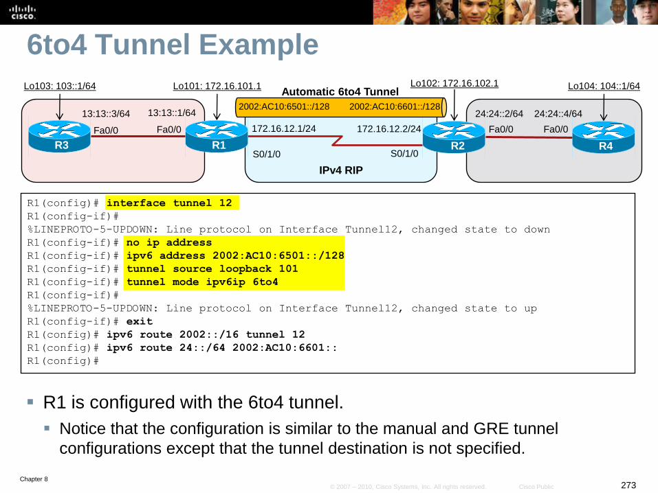
Chapter 8273© 2007 – 2010, Cisco Systems, Inc. All rights reserved. Cisco Public
6to4 Tunnel Example
R1 is configured with the 6to4 tunnel.
Notice that the configuration is similar to the manual and GRE tunnel
configurations except that the tunnel destination is not specified.
R1(config)# interface tunnel 12
R1(config-if)#
%LINEPROTO-5-UPDOWN: Line protocol on Interface Tunnel12, changed state to down
R1(config-if)# no ip address
R1(config-if)# ipv6 address 2002:AC10:6501::/128
R1(config-if)# tunnel source loopback 101
R1(config-if)# tunnel mode ipv6ip 6to4
R1(config-if)#
%LINEPROTO-5-UPDOWN: Line protocol on Interface Tunnel12, changed state to up
R1(config-if)# exit
R1(config)# ipv6 route 2002::/16 tunnel 12
R1(config)# ipv6 route 24::/64 2002:AC10:6601::
R1(config)#
S0/1/0 S0/1/0R1 R2
IPv4 RIP
Fa0/0
13:13::1/64
R3
Fa0/0
13:13::3/64 24:24::4/64
R4
Fa0/0
24:24::2/64
Fa0/0
Lo103: 103::1/64 Lo101: 172.16.101.1 Lo102: 172.16.102.1 Lo104: 104::1/64
172.16.12.1/24 172.16.12.2/24
Automatic 6to4 Tunnel
2002:AC10:6501::/128 2002:AC10:6601::/128
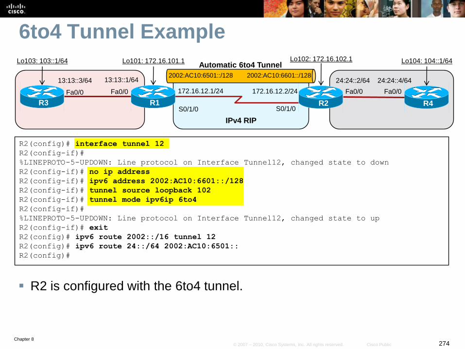
Chapter 8274© 2007 – 2010, Cisco Systems, Inc. All rights reserved. Cisco Public
6to4 Tunnel Example
R2 is configured with the 6to4 tunnel.
R2(config)# interface tunnel 12
R2(config-if)#
%LINEPROTO-5-UPDOWN: Line protocol on Interface Tunnel12, changed state to down
R2(config-if)# no ip address
R2(config-if)# ipv6 address 2002:AC10:6601::/128
R2(config-if)# tunnel source loopback 102
R2(config-if)# tunnel mode ipv6ip 6to4
R2(config-if)#
%LINEPROTO-5-UPDOWN: Line protocol on Interface Tunnel12, changed state to up
R2(config-if)# exit
R2(config)# ipv6 route 2002::/16 tunnel 12
R2(config)# ipv6 route 24::/64 2002:AC10:6501::
R2(config)#
S0/1/0 S0/1/0R1 R2
IPv4 RIP
Fa0/0
13:13::1/64
R3
Fa0/0
13:13::3/64 24:24::4/64
R4
Fa0/0
24:24::2/64
Fa0/0
Lo103: 103::1/64 Lo101: 172.16.101.1 Lo102: 172.16.102.1 Lo104: 104::1/64
172.16.12.1/24 172.16.12.2/24
Automatic 6to4 Tunnel
2002:AC10:6501::/128 2002:AC10:6601::/128
Chapter 8275© 2007 – 2010, Cisco Systems, Inc. All rights reserved. Cisco Public
ISATAP Tunnels
An Intra-Site Automatic Tunnel Addressing Protocol
(ISATAP) tunnel is very similar to a 6to4 IPv6 tunnel.
• It is used to connect IPv6 domains over an IPv4 network.
• It embeds an IPv4 address within the IPv6 address.
The goal of ISATAP is to provide connectivity for IPv6 hosts
to a centralized IPv6-capable router, over an IPv4-only
access network.
ISATAP was designed to transport IPv6 packets within a
site (hence the “intra-site” part of its name).
• It can still be used between sites, but its purpose is within sites.
ISATAP tunnels use IPv6 addresses consisting of a 64-bit
prefix concatenated to a 64-bit interface ID in EUI-64
format.
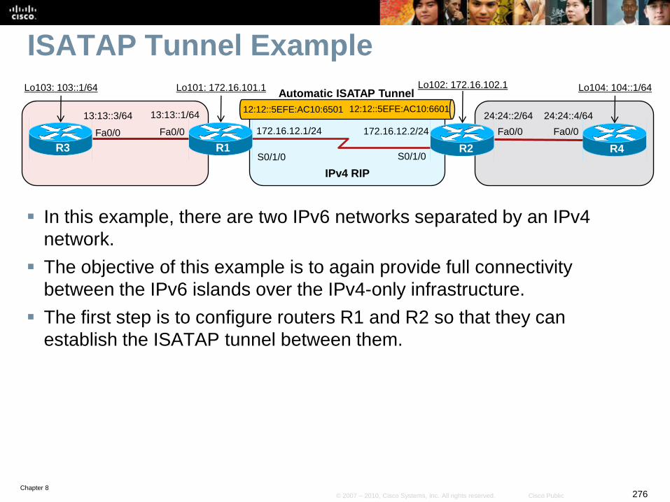
Chapter 8276© 2007 – 2010, Cisco Systems, Inc. All rights reserved. Cisco Public
ISATAP Tunnel Example
In this example, there are two IPv6 networks separated by an IPv4
network.
The objective of this example is to again provide full connectivity
between the IPv6 islands over the IPv4-only infrastructure.
The first step is to configure routers R1 and R2 so that they can
establish the ISATAP tunnel between them.
S0/1/0 S0/1/0R1 R2
IPv4 RIP
Fa0/0
13:13::1/64
R3
Fa0/0
13:13::3/64 24:24::4/64
R4
Fa0/0
24:24::2/64
Fa0/0
Lo103: 103::1/64 Lo101: 172.16.101.1 Lo102: 172.16.102.1 Lo104: 104::1/64
172.16.12.1/24 172.16.12.2/24
Automatic ISATAP Tunnel
12:12::5EFE:AC10:6501 12:12::5EFE:AC10:6601
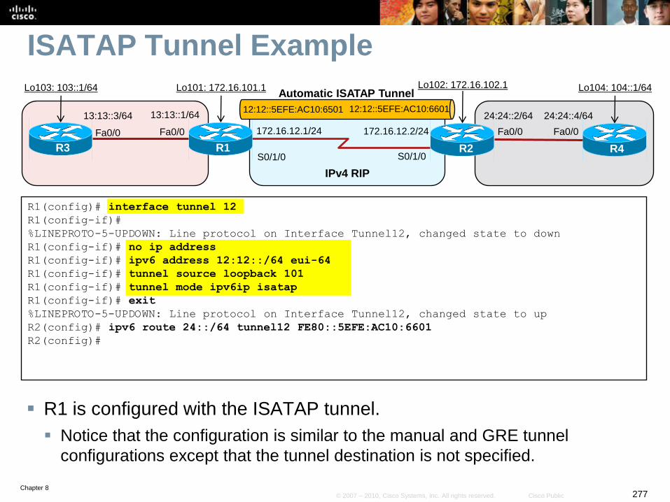
Chapter 8277© 2007 – 2010, Cisco Systems, Inc. All rights reserved. Cisco Public
ISATAP Tunnel Example
R1 is configured with the ISATAP tunnel.
Notice that the configuration is similar to the manual and GRE tunnel
configurations except that the tunnel destination is not specified.
R1(config)# interface tunnel 12
R1(config-if)#
%LINEPROTO-5-UPDOWN: Line protocol on Interface Tunnel12, changed state to down
R1(config-if)# no ip address
R1(config-if)# ipv6 address 12:12::/64 eui-64
R1(config-if)# tunnel source loopback 101
R1(config-if)# tunnel mode ipv6ip isatap
R1(config-if)# exit
%LINEPROTO-5-UPDOWN: Line protocol on Interface Tunnel12, changed state to up
R2(config)# ipv6 route 24::/64 tunnel12 FE80::5EFE:AC10:6601
R2(config)#
S0/1/0 S0/1/0R1 R2
IPv4 RIP
Fa0/0
13:13::1/64
R3
Fa0/0
13:13::3/64 24:24::4/64
R4
Fa0/0
24:24::2/64
Fa0/0
Lo103: 103::1/64 Lo101: 172.16.101.1 Lo102: 172.16.102.1 Lo104: 104::1/64
172.16.12.1/24 172.16.12.2/24
Automatic ISATAP Tunnel
12:12::5EFE:AC10:6501 12:12::5EFE:AC10:6601
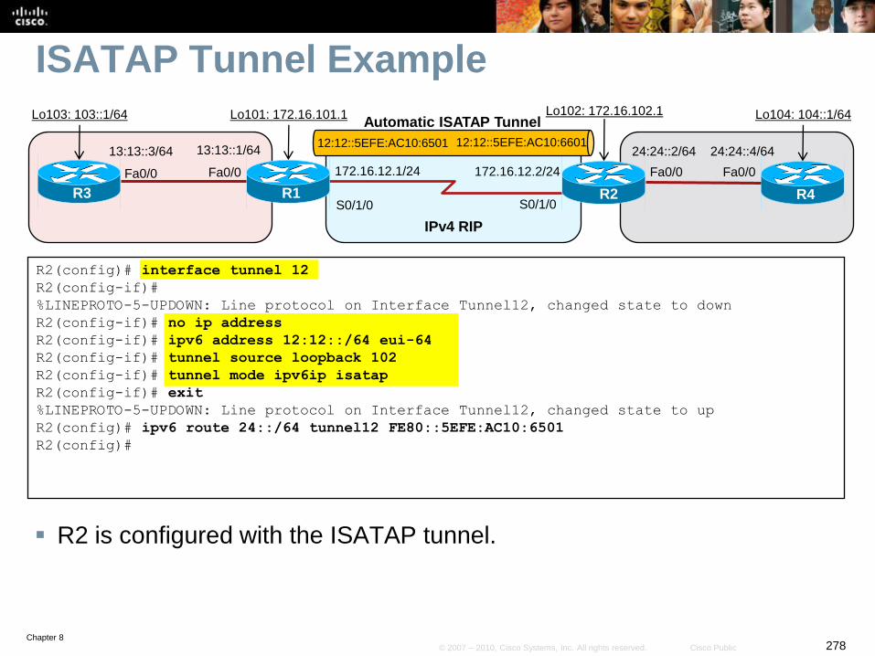
Chapter 8278© 2007 – 2010, Cisco Systems, Inc. All rights reserved. Cisco Public
ISATAP Tunnel Example
R2 is configured with the ISATAP tunnel.
R2(config)# interface tunnel 12
R2(config-if)#
%LINEPROTO-5-UPDOWN: Line protocol on Interface Tunnel12, changed state to down
R2(config-if)# no ip address
R2(config-if)# ipv6 address 12:12::/64 eui-64
R2(config-if)# tunnel source loopback 102
R2(config-if)# tunnel mode ipv6ip isatap
R2(config-if)# exit
%LINEPROTO-5-UPDOWN: Line protocol on Interface Tunnel12, changed state to up
R2(config)# ipv6 route 24::/64 tunnel12 FE80::5EFE:AC10:6501
R2(config)#
S0/1/0 S0/1/0R1 R2
IPv4 RIP
Fa0/0
13:13::1/64
R3
Fa0/0
13:13::3/64 24:24::4/64
R4
Fa0/0
24:24::2/64
Fa0/0
Lo103: 103::1/64 Lo101: 172.16.101.1 Lo102: 172.16.102.1 Lo104: 104::1/64
172.16.12.1/24 172.16.12.2/24
Automatic ISATAP Tunnel
12:12::5EFE:AC10:6501 12:12::5EFE:AC10:6601

Chapter 8279© 2007 – 2010, Cisco Systems, Inc. All rights reserved. Cisco Public
Translation Using NAT-PT
Chapter 8280© 2007 – 2010, Cisco Systems, Inc. All rights reserved. Cisco Public
NAT-PT
NAT-PT is another powerful transition technique, but is not
a replacement for dual stack or tunneling.
• Instead, it can be used in situations where direct communication
between IPv6-only and IPv4-only networks is desired.
• It would not be appropriate in situations where connectivity between
two IPv6 networks is required, because two points of translation would
be necessary, which would not be efficient or effective.
With NAT-PT, all configuration and translation is performed
on the NAT-PT router.
• The other devices in the network are not aware of the existence of the
other protocol’s network, nor that translations are occurring.
Chapter 8281© 2007 – 2010, Cisco Systems, Inc. All rights reserved. Cisco Public
NAT-PT
The NAT-PT router translates source and destination
addresses and other packet header fields in both directions:
• From the IPv4 network to the IPv6 network
• From the IPv6 network to the IPv4 network.
For this reason, this router is dual stacked and must have
two sets of translation entries for this bidirectional
translation.
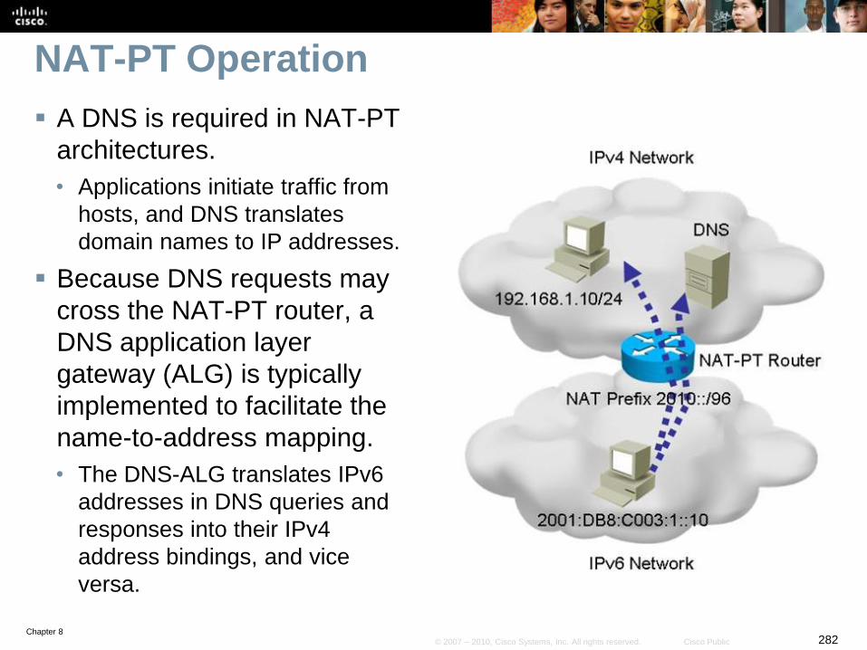
Chapter 8282© 2007 – 2010, Cisco Systems, Inc. All rights reserved. Cisco Public
NAT-PT Operation
A DNS is required in NAT-PT
architectures.
• Applications initiate traffic from
hosts, and DNS translates
domain names to IP addresses.
Because DNS requests may
cross the NAT-PT router, a
DNS application layer
gateway (ALG) is typically
implemented to facilitate the
name-to-address mapping.
• The DNS-ALG translates IPv6
addresses in DNS queries and
responses into their IPv4
address bindings, and vice
versa.
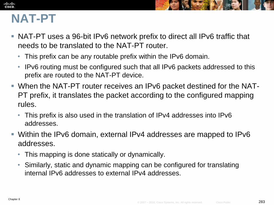
Chapter 8283© 2007 – 2010, Cisco Systems, Inc. All rights reserved. Cisco Public
NAT-PT
NAT-PT uses a 96-bit IPv6 network prefix to direct all IPv6 traffic that
needs to be translated to the NAT-PT router.
• This prefix can be any routable prefix within the IPv6 domain.
• IPv6 routing must be configured such that all IPv6 packets addressed to this
prefix are routed to the NAT-PT device.
When the NAT-PT router receives an IPv6 packet destined for the NAT-
PT prefix, it translates the packet according to the configured mapping
rules.
• This prefix is also used in the translation of IPv4 addresses into IPv6
addresses.
Within the IPv6 domain, external IPv4 addresses are mapped to IPv6
addresses.
• This mapping is done statically or dynamically.
• Similarly, static and dynamic mapping can be configured for translating
internal IPv6 addresses to external IPv4 addresses.
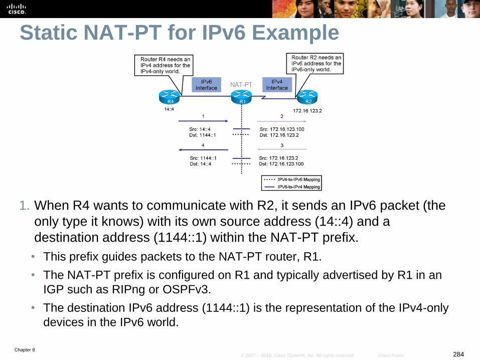
Chapter 8284© 2007 – 2010, Cisco Systems, Inc. All rights reserved. Cisco Public
Static NAT-PT for IPv6 Example
1. When R4 wants to communicate with R2, it sends an IPv6 packet (the
only type it knows) with its own source address (14::4) and a
destination address (1144::1) within the NAT-PT prefix.
• This prefix guides packets to the NAT-PT router, R1.
• The NAT-PT prefix is configured on R1 and typically advertised by R1 in an
IGP such as RIPng or OSPFv3.
• The destination IPv6 address (1144::1) is the representation of the IPv4-only
devices in the IPv6 world.
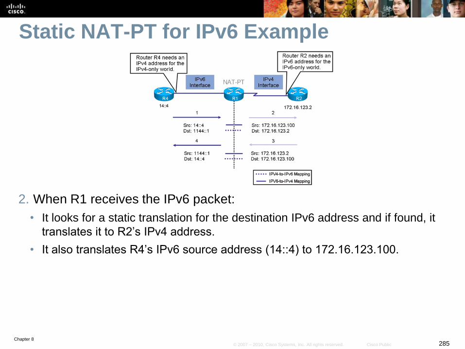
Chapter 8285© 2007 – 2010, Cisco Systems, Inc. All rights reserved. Cisco Public
Static NAT-PT for IPv6 Example
2. When R1 receives the IPv6 packet:
• It looks for a static translation for the destination IPv6 address and if found, it
translates it to R2’s IPv4 address.
• It also translates R4’s IPv6 source address (14::4) to 172.16.123.100.
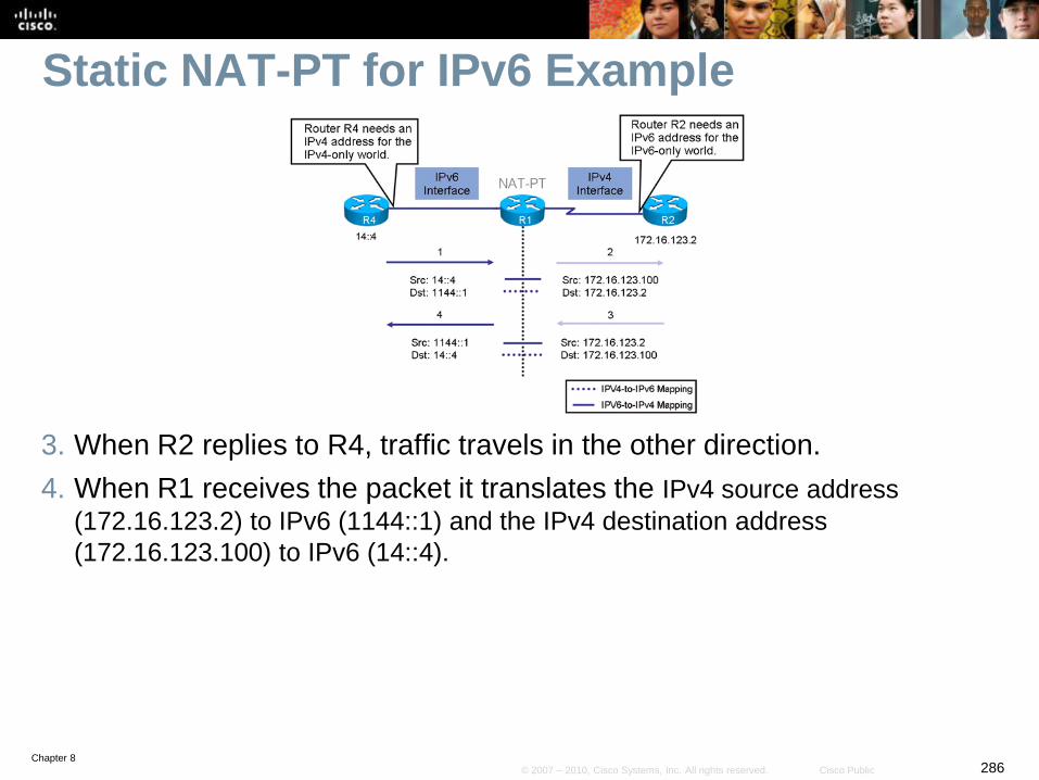
Chapter 8286© 2007 – 2010, Cisco Systems, Inc. All rights reserved. Cisco Public
Static NAT-PT for IPv6 Example
3. When R2 replies to R4, traffic travels in the other direction.
4. When R1 receives the packet it translates the IPv4 source address
(172.16.123.2) to IPv6 (1144::1) and the IPv4 destination address
(172.16.123.100) to IPv6 (14::4).
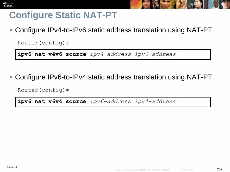
Chapter 8287© 2007 – 2010, Cisco Systems, Inc. All rights reserved. Cisco Public
Configure Static NAT-PT
Configure IPv4-to-IPv6 static address translation using NAT-PT.
Router(config)#
ipv6 nat v4v6 source ipv4-address ipv6-address
Configure IPv6-to-IPv4 static address translation using NAT-PT.
Router(config)#
ipv6 nat v6v4 source ipv6-address ipv4-address
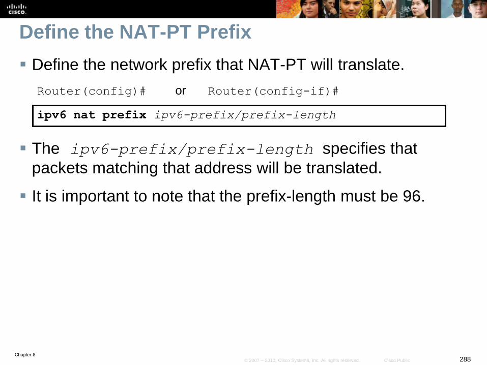
Chapter 8288© 2007 – 2010, Cisco Systems, Inc. All rights reserved. Cisco Public
Define the NAT-PT Prefix
Define the network prefix that NAT-PT will translate.
Router(config)# or Router(config-if)#
ipv6 nat prefix ipv6-prefix/prefix-length
The ipv6-prefix/prefix-length specifies that
packets matching that address will be translated.
It is important to note that the prefix-length must be 96.
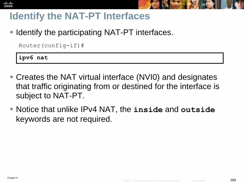
Chapter 8289© 2007 – 2010, Cisco Systems, Inc. All rights reserved. Cisco Public
Identify the NAT-PT Interfaces
Identify the participating NAT-PT interfaces.
Router(config-if)#
ipv6 nat
Creates the NAT virtual interface (NVI0) and designates that traffic originating from or destined for the interface is subject to NAT-PT.
Notice that unlike IPv4 NAT, the inside and outside
keywords are not required.
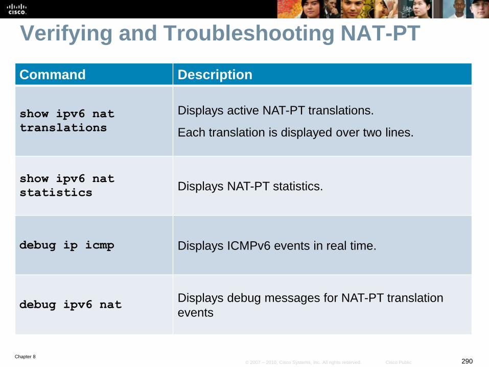
Chapter 8290© 2007 – 2010, Cisco Systems, Inc. All rights reserved. Cisco Public
Verifying and Troubleshooting NAT-PT
Command Description
show ipv6 nat
translations
Displays active NAT-PT translations.
Each translation is displayed over two lines.
show ipv6 nat
statisticsDisplays NAT-PT statistics.
debug ip icmp Displays ICMPv6 events in real time.
debug ipv6 natDisplays debug messages for NAT-PT translation
events
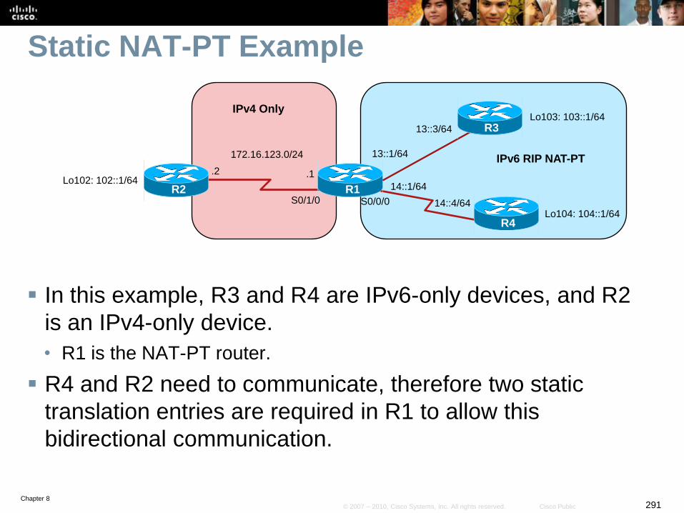
Chapter 8291© 2007 – 2010, Cisco Systems, Inc. All rights reserved. Cisco Public
Static NAT-PT Example
In this example, R3 and R4 are IPv6-only devices, and R2
is an IPv4-only device.
• R1 is the NAT-PT router.
R4 and R2 need to communicate, therefore two static
translation entries are required in R1 to allow this
bidirectional communication.
R1
R3
R4
172.16.123.0/24
.1
S0/0/0R2
S0/1/0
Lo102: 102::1/6414::1/64
14::4/64
.2
Lo103: 103::1/64
Lo104: 104::1/64
13::1/64
13::3/64
IPv6 RIP NAT-PT
IPv4 Only
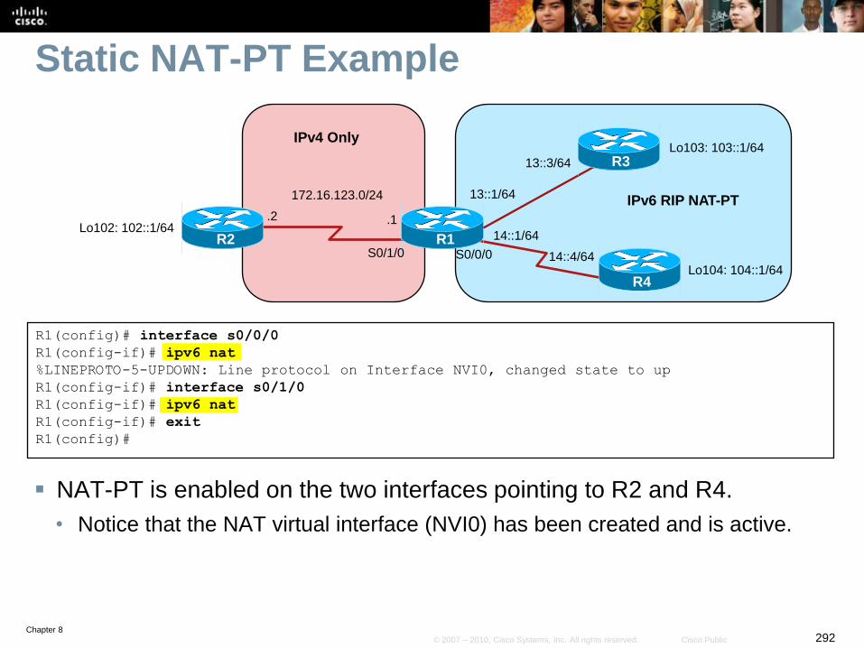
Chapter 8292© 2007 – 2010, Cisco Systems, Inc. All rights reserved. Cisco Public
Static NAT-PT Example
NAT-PT is enabled on the two interfaces pointing to R2 and R4.
• Notice that the NAT virtual interface (NVI0) has been created and is active.
R1(config)# interface s0/0/0
R1(config-if)# ipv6 nat
%LINEPROTO-5-UPDOWN: Line protocol on Interface NVI0, changed state to up
R1(config-if)# interface s0/1/0
R1(config-if)# ipv6 nat
R1(config-if)# exit
R1(config)#
R1
R3
R4
172.16.123.0/24
.1
S0/0/0R2
S0/1/0
Lo102: 102::1/6414::1/64
14::4/64
.2
Lo103: 103::1/64
Lo104: 104::1/64
13::1/64
13::3/64
IPv6 RIP NAT-PT
IPv4 Only
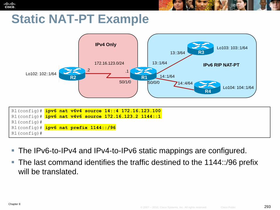
Chapter 8293© 2007 – 2010, Cisco Systems, Inc. All rights reserved. Cisco Public
Static NAT-PT Example
The IPv6-to-IPv4 and IPv4-to-IPv6 static mappings are configured.
The last command identifies the traffic destined to the 1144::/96 prefix
will be translated.
R1(config)# ipv6 nat v6v4 source 14::4 172.16.123.100
R1(config)# ipv6 nat v4v6 source 172.16.123.2 1144::1
R1(config)#
R1(config)# ipv6 nat prefix 1144::/96
R1(config)#
R1
R3
R4
172.16.123.0/24
.1
S0/0/0R2
S0/1/0
Lo102: 102::1/6414::1/64
14::4/64
.2
Lo103: 103::1/64
Lo104: 104::1/64
13::1/64
13::3/64
IPv6 RIP NAT-PT
IPv4 Only
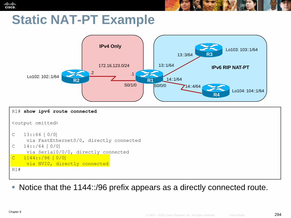
Chapter 8294© 2007 – 2010, Cisco Systems, Inc. All rights reserved. Cisco Public
Static NAT-PT Example
Notice that the 1144::/96 prefix appears as a directly connected route.
R1# show ipv6 route connected
<output omitted>
C 13::64 [0/0]
via FastEthernet0/0, directly connected
C 14::/64 [0/0]
via Serial0/0/0, directly connected
C 1144::/96 [0/0]
via NVI0, directly connected
R1#
R1
R3
R4
172.16.123.0/24
.1
S0/0/0R2
S0/1/0
Lo102: 102::1/6414::1/64
14::4/64
.2
Lo103: 103::1/64
Lo104: 104::1/64
13::1/64
13::3/64
IPv6 RIP NAT-PT
IPv4 Only
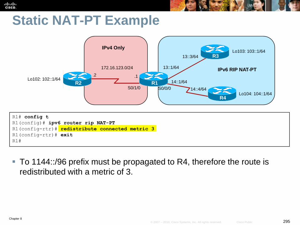
Chapter 8295© 2007 – 2010, Cisco Systems, Inc. All rights reserved. Cisco Public
Static NAT-PT Example
To 1144::/96 prefix must be propagated to R4, therefore the route is
redistributed with a metric of 3.
R1# config t
R1(config)# ipv6 router rip NAT-PT
R1(config-rtr)# redistribute connected metric 3
R1(config-rtr)# exit
R1#
R1
R3
R4
172.16.123.0/24
.1
S0/0/0R2
S0/1/0
Lo102: 102::1/6414::1/64
14::4/64
.2
Lo103: 103::1/64
Lo104: 104::1/64
13::1/64
13::3/64
IPv6 RIP NAT-PT
IPv4 Only
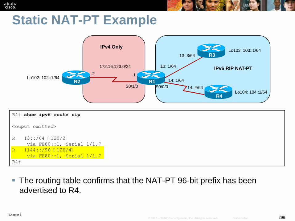
Chapter 8296© 2007 – 2010, Cisco Systems, Inc. All rights reserved. Cisco Public
Static NAT-PT Example
The routing table confirms that the NAT-PT 96-bit prefix has been
advertised to R4.
R4# show ipv6 route rip
<ouput omitted>
R 13::/64 [120/2]
via FE80::1, Serial 1/1.7
R 1144::/96 [120/4]
via FE80::1, Serial 1/1.7
R4#
R1
R3
R4
172.16.123.0/24
.1
S0/0/0R2
S0/1/0
Lo102: 102::1/6414::1/64
14::4/64
.2
Lo103: 103::1/64
Lo104: 104::1/64
13::1/64
13::3/64
IPv6 RIP NAT-PT
IPv4 Only
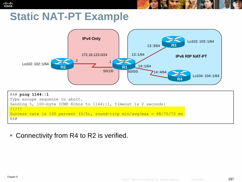
Chapter 8297© 2007 – 2010, Cisco Systems, Inc. All rights reserved. Cisco Public
Static NAT-PT Example
Connectivity from R4 to R2 is verified.
R4# ping 1144::1
Type escape sequence to abort.
Sending 5, 100-byte ICMP Echos to 1144::1, timeout is 2 seconds:
!!!!!
Success rate is 100 percent (5/5), round-trip min/avg/max = 68/70/73 ms
R4#
R1
R3
R4
172.16.123.0/24
.1
S0/0/0R2
S0/1/0
Lo102: 102::1/6414::1/64
14::4/64
.2
Lo103: 103::1/64
Lo104: 104::1/64
13::1/64
13::3/64
IPv6 RIP NAT-PT
IPv4 Only
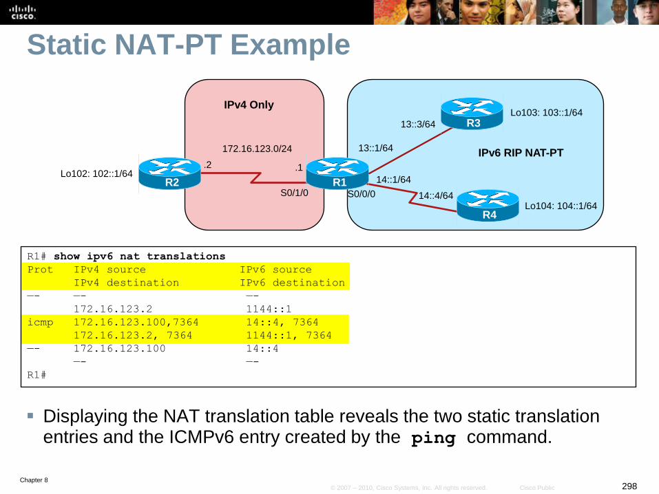
Chapter 8298© 2007 – 2010, Cisco Systems, Inc. All rights reserved. Cisco Public
Static NAT-PT Example
Displaying the NAT translation table reveals the two static translation entries and the ICMPv6 entry created by the ping command.
R1
R3
R4
172.16.123.0/24
.1
S0/0/0R2
S0/1/0
Lo102: 102::1/6414::1/64
14::4/64
.2
Lo103: 103::1/64
Lo104: 104::1/64
13::1/64
13::3/64
IPv6 RIP NAT-PT
IPv4 Only
R1# show ipv6 nat translations
Prot IPv4 source IPv6 source
IPv4 destination IPv6 destination
—- —- —-
172.16.123.2 1144::1
icmp 172.16.123.100,7364 14::4, 7364
172.16.123.2, 7364 1144::1, 7364
—- 172.16.123.100 14::4
—- —-
R1#
Chapter 8299© 2007 – 2010, Cisco Systems, Inc. All rights reserved. Cisco Public
Static NAT Summary
Static NAT-PT is quite simple to configure and a good
solution for one or two sites.
Therefore a big drawback of static NAT is that it is not
scalable.
• It’s very cumbersome to create static entries for multiple sources
communicating with multiple destinations.
Dynamic NAT provides a far more scalable solution.
Chapter 8300© 2007 – 2010, Cisco Systems, Inc. All rights reserved. Cisco Public
Dynamic NAT-PT for IPv6
With dynamic NAT-PT, addresses are allocated from an
address pool, the same as is done with IPv4 dynamic NAT.
• Again, the commands have similar syntax to their IPv4 NAT.
When the NAT-PT router receives a packet with an IPv6
destination address of an arbitrarily assigned 96-bit prefix
(the NAT-PT prefix), it translates the IPv6 packet to an IPv4
address from an address pool.
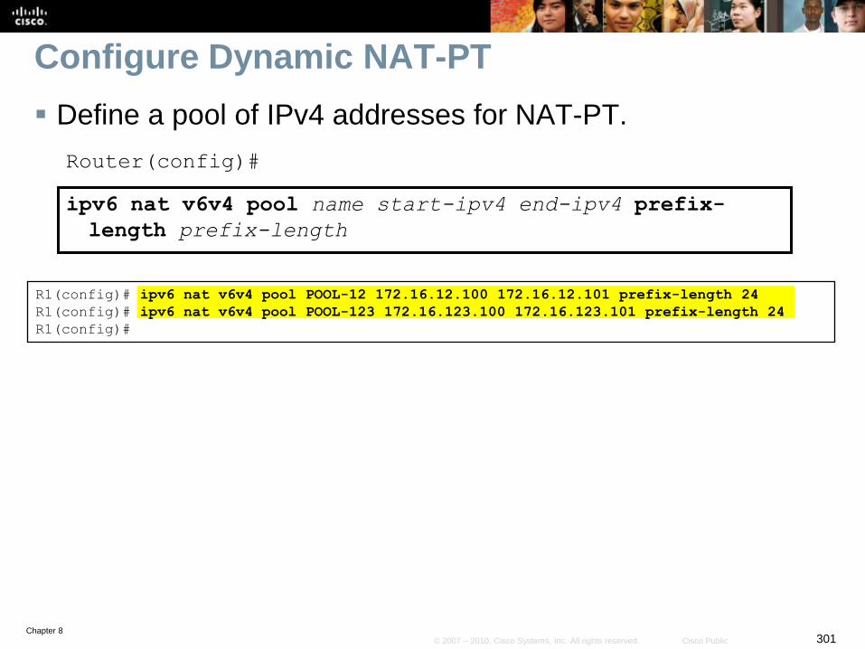
Chapter 8301© 2007 – 2010, Cisco Systems, Inc. All rights reserved. Cisco Public
Configure Dynamic NAT-PT
Define a pool of IPv4 addresses for NAT-PT.
Router(config)#
ipv6 nat v6v4 pool name start-ipv4 end-ipv4 prefix-
length prefix-length
R1(config)# ipv6 nat v6v4 pool POOL-12 172.16.12.100 172.16.12.101 prefix-length 24
R1(config)# ipv6 nat v6v4 pool POOL-123 172.16.123.100 172.16.123.101 prefix-length 24
R1(config)#
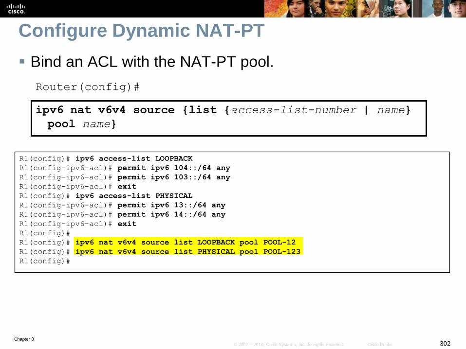
Chapter 8302© 2007 – 2010, Cisco Systems, Inc. All rights reserved. Cisco Public
Configure Dynamic NAT-PT
Bind an ACL with the NAT-PT pool.
Router(config)#
ipv6 nat v6v4 source {list {access-list-number | name}
pool name}
R1(config)# ipv6 access-list LOOPBACK
R1(config-ipv6-acl)# permit ipv6 104::/64 any
R1(config-ipv6-acl)# permit ipv6 103::/64 any
R1(config-ipv6-acl)# exit
R1(config)# ipv6 access-list PHYSICAL
R1(config-ipv6-acl)# permit ipv6 13::/64 any
R1(config-ipv6-acl)# permit ipv6 14::/64 any
R1(config-ipv6-acl)# exit
R1(config)#
R1(config)# ipv6 nat v6v4 source list LOOPBACK pool POOL-12
R1(config)# ipv6 nat v6v4 source list PHYSICAL pool POOL-123
R1(config)#
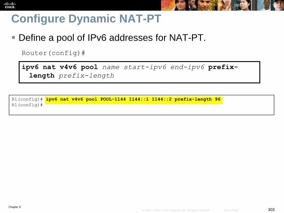
Chapter 8303© 2007 – 2010, Cisco Systems, Inc. All rights reserved. Cisco Public
Configure Dynamic NAT-PT
Define a pool of IPv6 addresses for NAT-PT.
Router(config)#
ipv6 nat v4v6 pool name start-ipv6 end-ipv6 prefix-
length prefix-length
R1(config)# ipv6 nat v4v6 pool POOL-1144 1144::1 1144::2 prefix-length 96
R1(config)#
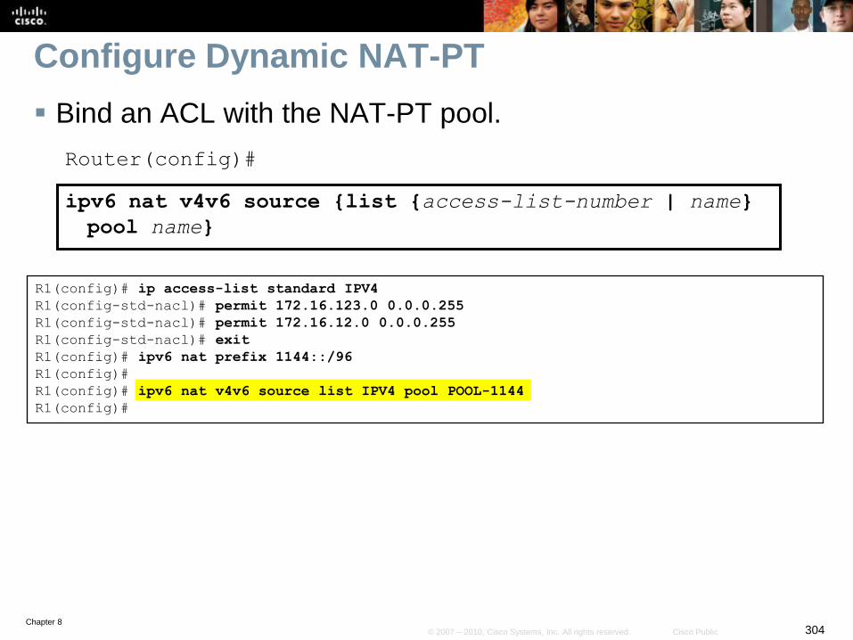
Chapter 8304© 2007 – 2010, Cisco Systems, Inc. All rights reserved. Cisco Public
Configure Dynamic NAT-PT
Bind an ACL with the NAT-PT pool.
Router(config)#
ipv6 nat v4v6 source {list {access-list-number | name}
pool name}
R1(config)# ip access-list standard IPV4
R1(config-std-nacl)# permit 172.16.123.0 0.0.0.255
R1(config-std-nacl)# permit 172.16.12.0 0.0.0.255
R1(config-std-nacl)# exit
R1(config)# ipv6 nat prefix 1144::/96
R1(config)#
R1(config)# ipv6 nat v4v6 source list IPV4 pool POOL-1144
R1(config)#
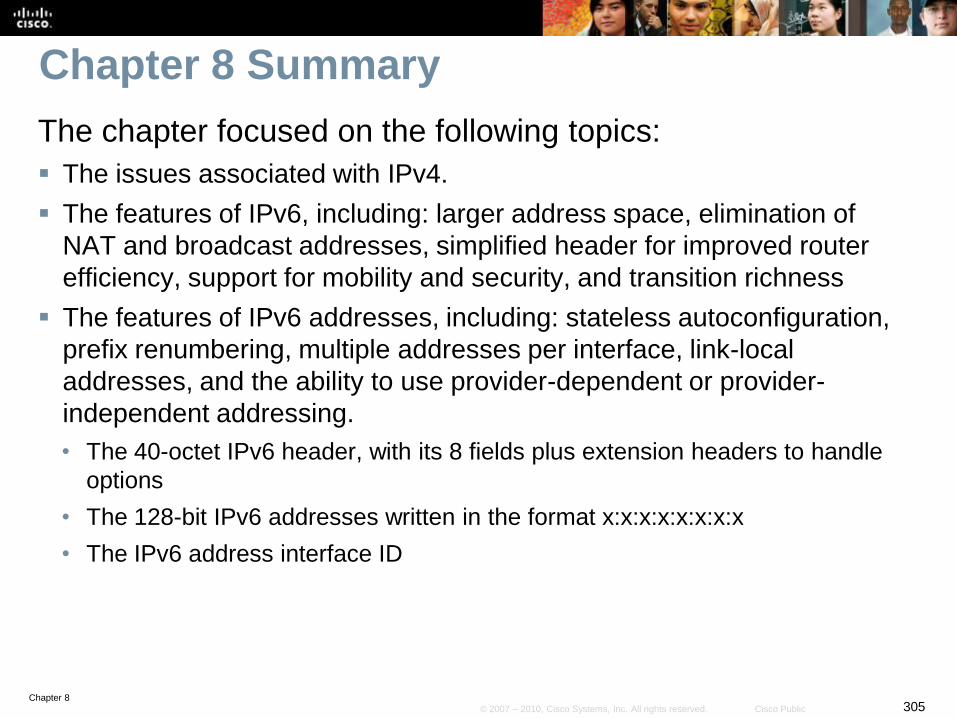
Chapter 8305© 2007 – 2010, Cisco Systems, Inc. All rights reserved. Cisco Public
Chapter 8 Summary
The chapter focused on the following topics:
The issues associated with IPv4.
The features of IPv6, including: larger address space, elimination of
NAT and broadcast addresses, simplified header for improved router
efficiency, support for mobility and security, and transition richness
The features of IPv6 addresses, including: stateless autoconfiguration,
prefix renumbering, multiple addresses per interface, link-local
addresses, and the ability to use provider-dependent or provider-
independent addressing.
• The 40-octet IPv6 header, with its 8 fields plus extension headers to handle
options
• The 128-bit IPv6 addresses written in the format x:x:x:x:x:x:x:x
• The IPv6 address interface ID
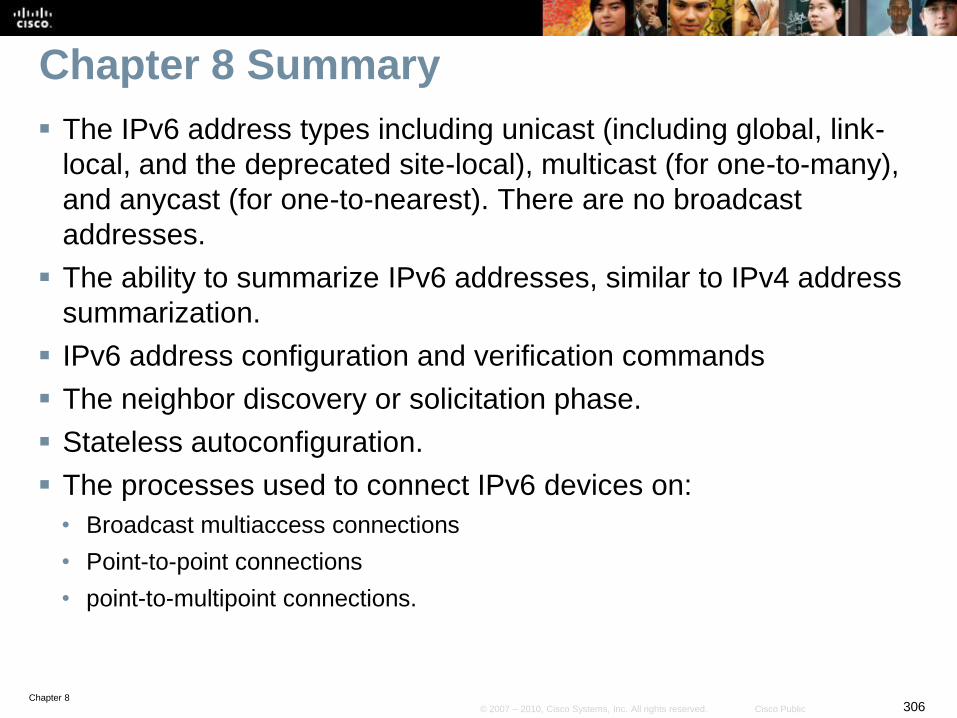
Chapter 8306© 2007 – 2010, Cisco Systems, Inc. All rights reserved. Cisco Public
Chapter 8 Summary
The IPv6 address types including unicast (including global, link-
local, and the deprecated site-local), multicast (for one-to-many),
and anycast (for one-to-nearest). There are no broadcast
addresses.
The ability to summarize IPv6 addresses, similar to IPv4 address
summarization.
IPv6 address configuration and verification commands
The neighbor discovery or solicitation phase.
Stateless autoconfiguration.
The processes used to connect IPv6 devices on:
• Broadcast multiaccess connections
• Point-to-point connections
• point-to-multipoint connections.
Chapter 8307© 2007 – 2010, Cisco Systems, Inc. All rights reserved. Cisco Public
Chapter 8 Summary
The routing protocols available for IPv6, including RIPng,
OSPFv3, EIGRP for IPv6, and MBGP
The types of static routes that can be configured.
RIPng features, configuration and verification commands
OSPFv3 features, configuration and verification commands
EIGRP for IPv6 features, configuration and verification
commands
MBGP features, configuration and verification commands
Policy routing configuration and verification commands.
Redistribution configuration and verification commands.
Chapter 8308© 2007 – 2010, Cisco Systems, Inc. All rights reserved. Cisco Public
Chapter 8 Summary
Transitioning techniques from IPv4 to IPv6:
• Dual-stack (both protocols running)
• Tunneling IPv6 inside IPv4
• Translation with stateful NAT-PT
Tunneling IPv6 over IPv4:
• Manual tunnels, configuration and verification commands.
• GRE tunnels, configuration and verification commands.
• 6to4 tunnels, configuration and verification commands.
• ISATAP tunnels, configuration and verification commands.
Translation using NAT-PT.
Static NAT-PT configuration and verification commands.
Dynamic NAT-PT configuration and verification commands
Chapter 8309© 2007 – 2010, Cisco Systems, Inc. All rights reserved. Cisco Public
Resources
IPv6 Main Page
www.cisco.com/go/ipv6
IPv6 Headers At-a-Glance
http://www.cisco.com/en/US/technologies/tk648/tk872/technologies_white_paper0900aecd80260042.pdf
The Cisco IOS Software Releases 12.4 Mainline Command References, available at:
http://www.cisco.com/en/US/products/ps6350/prod_command_reference_list.html
The Cisco IOS IPv6 Command Reference, available at:
http://www.cisco.com/en/US/docs/ios/ipv6/command/reference/ipv6_book.html
The Cisco IOS IPv6 Configuration Guide, Release 12.4, available at:
http://www.cisco.com/en/US/docs/ios/ipv6/configuration/guide/12_4/ipv6_12_4_book.html
Cisco IOS IPv6 Multicast Introduction, available at:
http://www.cisco.com/en/US/tech/tk828/technologies_white_paper09186a0080203e90.shtml
Chapter 8310© 2007 – 2010, Cisco Systems, Inc. All rights reserved. Cisco Public
Resources
IPv6.com
http://www.ipv6.com/index.htm
Planning Guide / Roadmap Toward IPv6 Adoption
http://www.cio.gov/documents_details.cfm/uid/1F4376CF-2170-9AD7-
F24F363D0A04637E/structure/Enterprise%20Architecture/category/IPv
6
Chapter 8311© 2007 – 2010, Cisco Systems, Inc. All rights reserved. Cisco Public
Chapter Labs
Lab 8-1 Configuring OSPF for IPv6
Lab 8-2 Using Manual IPv6 Tunnels with EIGRP for IPv6
Lab 8-3 Configuring 6to4 Tunnels
Lab 8-4 IPv6 Challenge Lab
Lab 8-5 IPv6 Troubleshooting Lab

Chapter 8312© 2007 – 2010, Cisco Systems, Inc. All rights reserved. Cisco Public


