41
Routing Overlays and Virtualization (Nick Feamster) February 13, 2008
| Date post: | 16-Dec-2015 |
| Category: |
Documents |
| Upload: | owen-lewis |
| View: | 219 times |
| Download: | 2 times |
Routing Overlays and Virtualization
(Nick Feamster)February 13, 2008
2
Today’s Lecture
• Routing Overlays: Resilient Overlay Networks– Motivation– Basic Operation– Problems: scaling, synchronization, etc.– Other applications: security
• Other Kinds of Network Virtualization (e.g., BGP/MPLS VPNs)
3
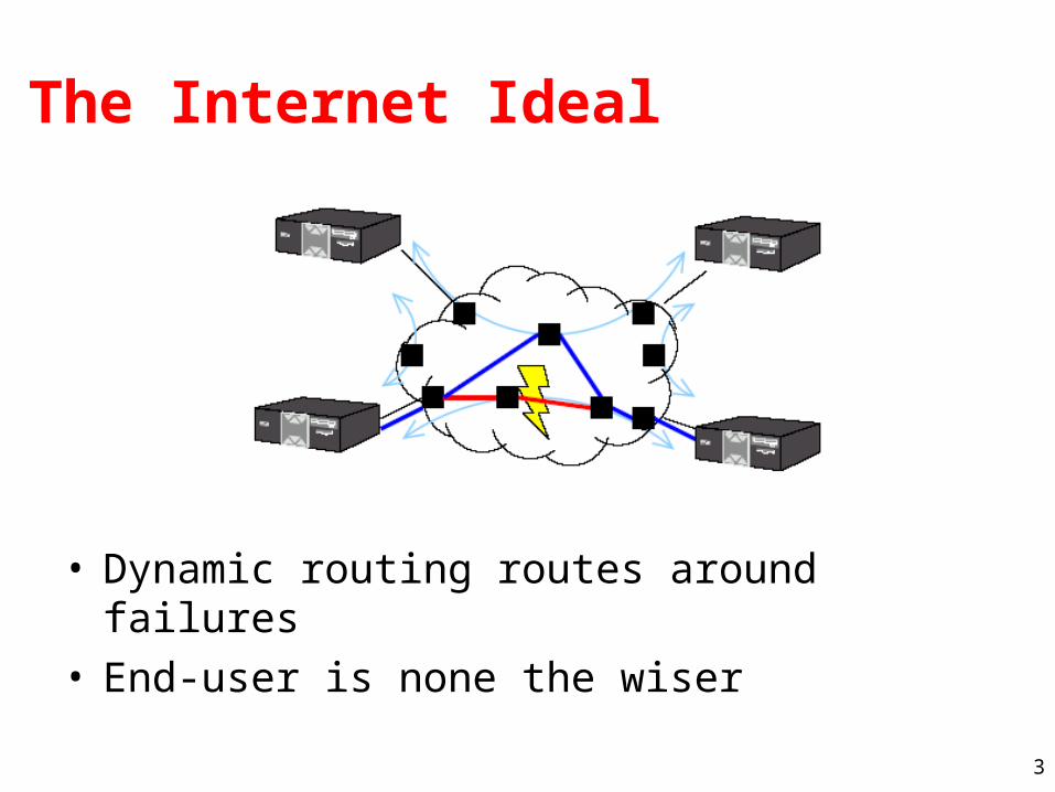
The Internet Ideal
• Dynamic routing routes around failures• End-user is none the wiser
4
Lesson from Routing Overlays
• End-hosts can measure path performance metrics on the (small number of) paths that matter
• Internet routing scales well, but at the cost of performance
End-hosts are often better informed about performance and reachability problems than routers.
5
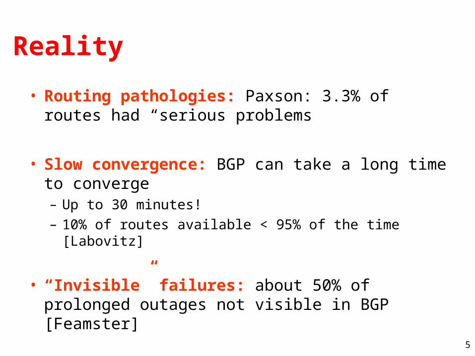
Reality
• Routing pathologies: Paxson: 3.3% of routes had “serious problems
• Slow convergence: BGP can take a long time to converge– Up to 30 minutes!– 10% of routes available < 95% of the time [Labovitz]
• “Invisible” failures: about 50% of prolonged outages not visible in BGP [Feamster]
6
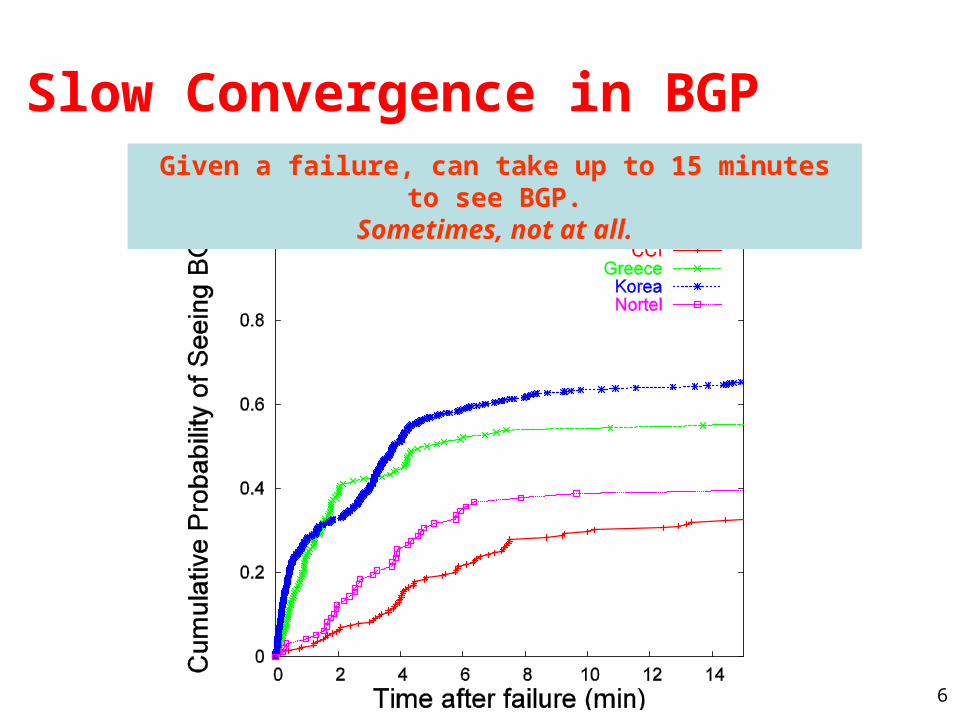
Slow Convergence in BGPGiven a failure, can take up to 15 minutes to see BGP.
Sometimes, not at all.
7
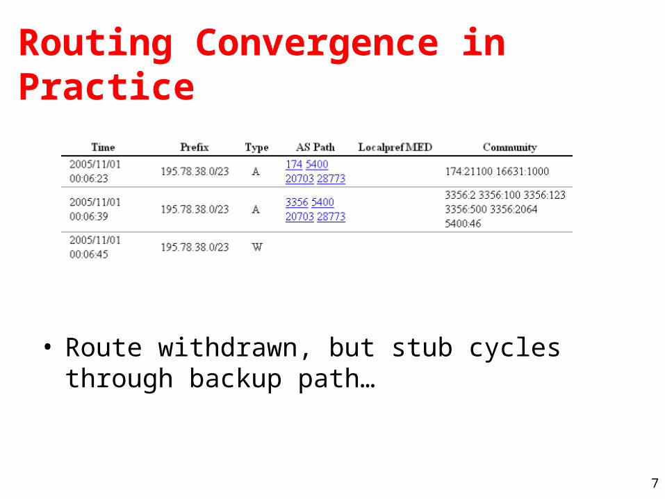
Routing Convergence in Practice
• Route withdrawn, but stub cycles through backup path…
8
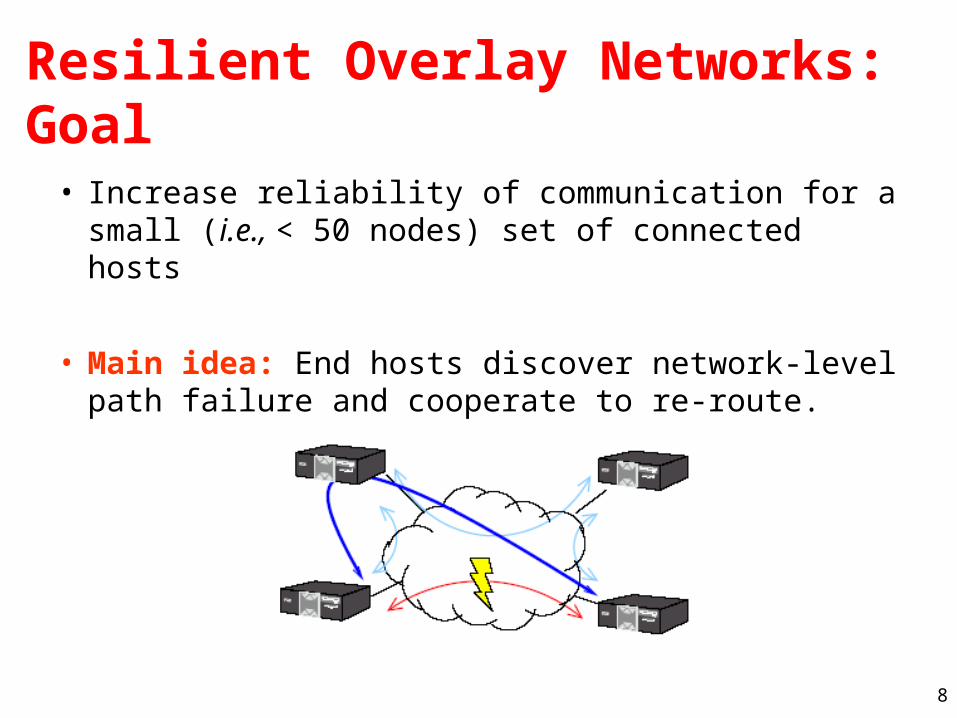
Resilient Overlay Networks: Goal
• Increase reliability of communication for a small (i.e., < 50 nodes) set of connected hosts
• Main idea: End hosts discover network-level path failure and cooperate to re-route.
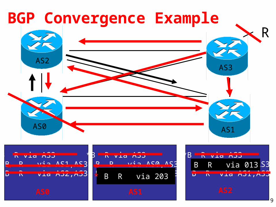
9
R
AS0 AS1
AS2AS3
*B R via AS3 B R via AS0,AS3 B R via AS2,AS3
*B R via AS3 B R via AS0,AS3 B R via AS1,AS3
*B R via AS3 B R via AS1,AS3 B R via AS2,AS3
AS0 AS1 AS2
BGP Convergence Example
** * B R via 203 *
B R via 013 *
10
Intuition for Delayed BGP Convergence• There exists a message ordering for which BGP will
explore all possible AS paths• Convergence is O(N!), where N is the number of
default-free BGP speakers in a complete graph• C. Labovitz, A. Ahuja, A. Bose, and F. Jahanian,
“Delayed Internet routing convergence,” Proceedings of SIGCOMM, 2000.
• In practice, exploration can take 15-30 minutes• Question: What typically prevents this exploration
from happening in practice?
• Question: Why can’t BGP simply eliminate all paths containing a subpath when the subpath is withdrawn?

11
The RON Architecture
• Outage detection– Active UDP-based probing
• On average every 14 seconds• O(n2)
– 3-way probe• Both sides get RTT information• Store latency and loss-rate information in DB
• Routing protocol: Link-state between overlay nodes
• Policy: restrict some paths from hosts– E.g., don’t use Internet2 hosts to improve non-Internet2 paths
12
Main results
• RON can route around failures in ~ 10 seconds
• Often improves latency, loss, and throughput
• Single-hop indirection works well enough– Motivation for second paper (SOSR)– Also begs the question about the benefits of overlays
13
When (and why) does RON work?
• Location: Where do failures appear?– A few paths experience many failures, but many paths experience
at least a few failures (80% of failures on 20% of links).
• Duration: How long do failures last?– 70% of failures last less than 5 minutes
• Correlation: Do failures correlate with BGP instability?– BGP updates often coincide with failures– Failures near end hosts less likely to coincide with BGP– Sometimes, BGP updates precede failures (why?)
Feamster et al., Measuring the Effects of Internet Path Faults on Reactive Routing, SIGMETRICS 2003
14
Location of Failures
• Why it matters: failures closer to the edge are more difficult to route around, particularly last-hop failures– RON testbed study (2003): About 60% of failures
within two hops of the edge– SOSR study (2004): About half of failures potentially
recoverable with one-hop source routing• Harder to route around broadband failures (why?)
15
Benefits of Overlays
• Access to multiple paths– Provided by BGP multihoming
• Fast outage detection– But…requires aggressive probing; doesn’t scale
Question: What benefits does overlay routing provide over traditional multihoming + intelligent routing (e.g., RouteScience)?
A Comparison of Overlay Routing and Multihoming Route Control, A. Akella, J. Pang, A. Shaikh, B. Maggs, and S. Seshan. Proceedings of the ACM SIGCOMM 2004 Conference (SIGCOMM), August, 2004.
16
Open Questions
• Efficiency– Requires redundant traffic on access links
• Scaling– Can a RON be made to scale to > 50 nodes?– How to achieve probing efficiency?
• Interaction of overlays and IP network• Interaction of multiple overlays
17
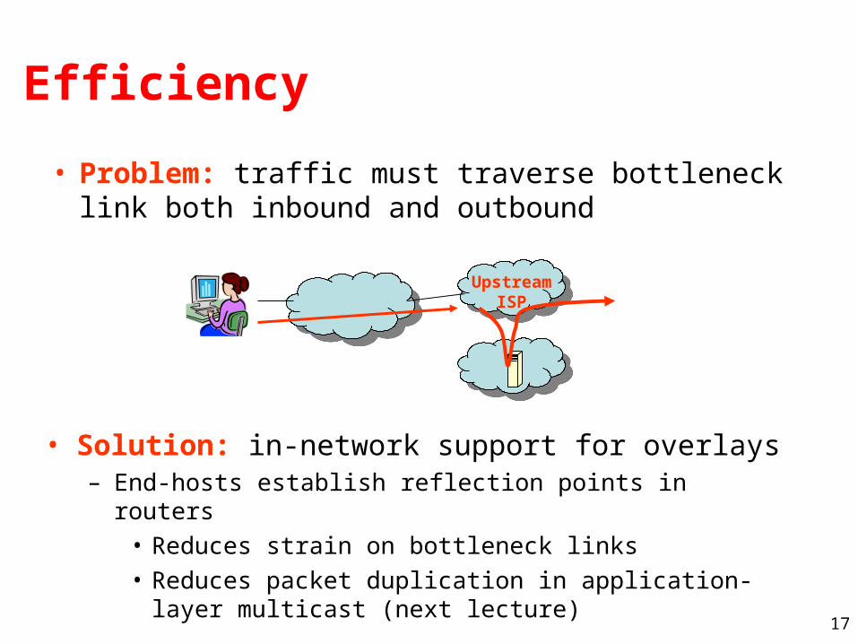
Efficiency
• Problem: traffic must traverse bottleneck link both inbound and outbound
• Solution: in-network support for overlays– End-hosts establish reflection points in routers
• Reduces strain on bottleneck links• Reduces packet duplication in application-layer multicast
(next lecture)
Upstream ISP
18
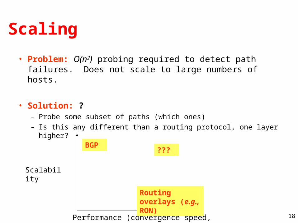
Scaling
• Problem: O(n2) probing required to detect path failures. Does not scale to large numbers of hosts.
• Solution: ?– Probe some subset of paths (which ones)– Is this any different than a routing protocol, one layer higher?
Scalability
Performance (convergence speed, etc.)
BGP
Routing overlays (e.g., RON)
???
19
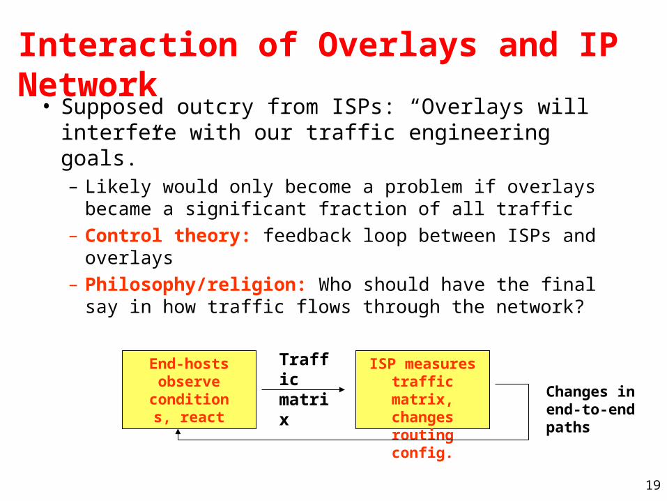
Interaction of Overlays and IP Network• Supposed outcry from ISPs: “Overlays will
interfere with our traffic engineering goals.”– Likely would only become a problem if overlays
became a significant fraction of all traffic– Control theory: feedback loop between ISPs and
overlays– Philosophy/religion: Who should have the final say
in how traffic flows through the network?
End-hostsobserve
conditions, react
ISP measures traffic matrix,
changes routing config.
Traffic matrix
Changes in end-to-end paths
20
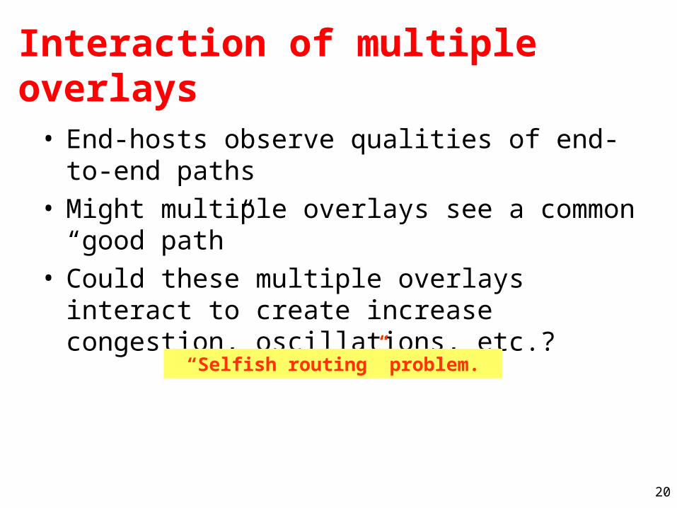
Interaction of multiple overlays
• End-hosts observe qualities of end-to-end paths• Might multiple overlays see a common “good
path”• Could these multiple overlays interact to create
increase congestion, oscillations, etc.?
“Selfish routing” problem.
21
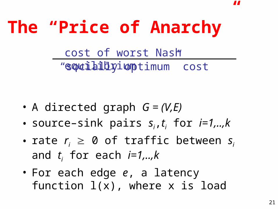
The “Price of Anarchy”cost of worst Nash equilibrium
“socially optimum” cost
• A directed graph G = (V,E)
• source–sink pairs si,ti for i=1,..,k
• rate ri 0 of traffic between si and ti for each i=1,..,k
• For each edge e, a latency function l(x), where x is load
22
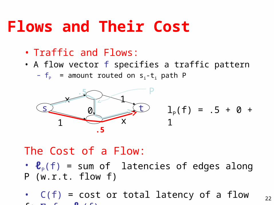
Flows and Their Cost
• Traffic and Flows:• A flow vector f specifies a traffic pattern
– fP = amount routed on si-ti path P
The Cost of a Flow:• ℓP(f) = sum of latencies of edges along P (w.r.t. flow f)
• C(f) = cost or total latency of a flow f: P fP • ℓP(f)
lP(f) = .5 + 0 + 1
.5
P
s tx 1
.5
x10
23
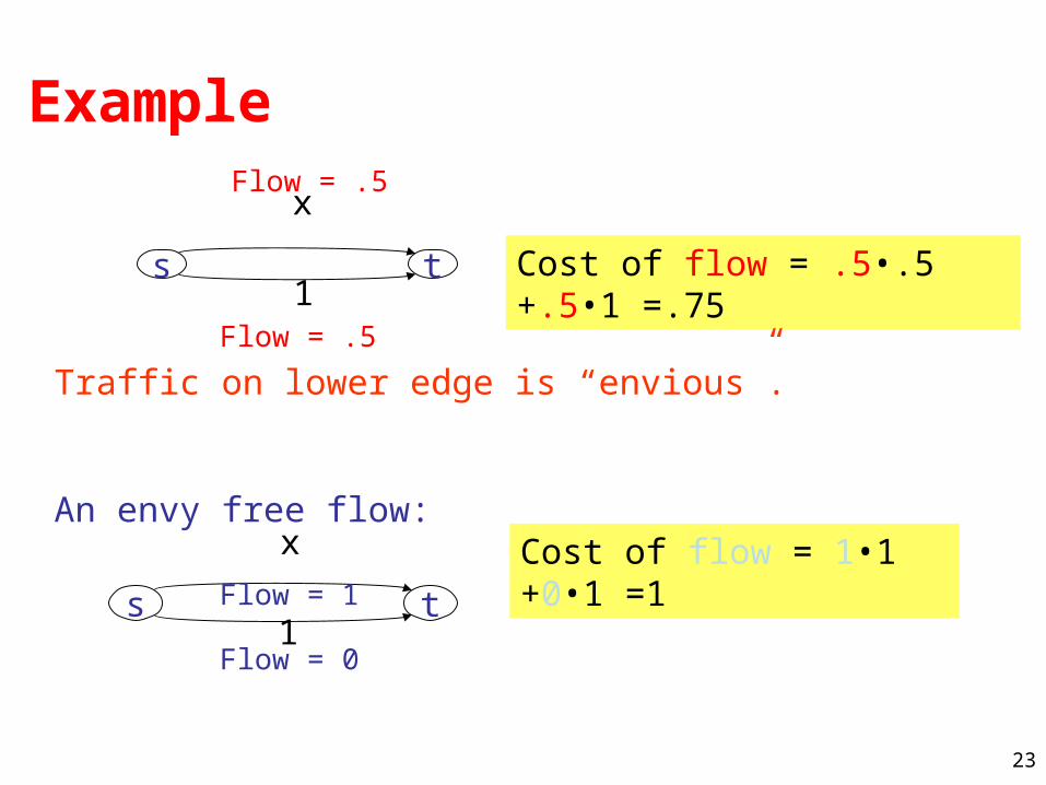
Example
x
s t1
Flow = .5
Flow = .5
Cost of flow = .5•.5 +.5•1 =.75
Traffic on lower edge is “envious”.
An envy free flow:x
s t1
Flow = 0
Flow = 1
Cost of flow = 1•1 +0•1 =1
24
Flows and Game Theory
• Flow: routes of many noncooperative agents– each agent controlling infinitesimally small amount
• cars in a highway system• packets in a network
• The toal latency of a flow represents social welfare
• Agents are selfish, and want to minimize their own latency
25
Flows at Nash Equilibrium
• A flow is at Nash equilibrium (or is a Nash flow) if no agent can improve its latency by changing its path
– Assumption: edge latency functions are continuous, and non-decreasing
• Lemma: a flow f is at Nash equilibrium if and only if all flow travels along minimum-latency paths between its source and destination (w.r.t. f)
• Theorem: The Nash equilibrium exists and is unique
26
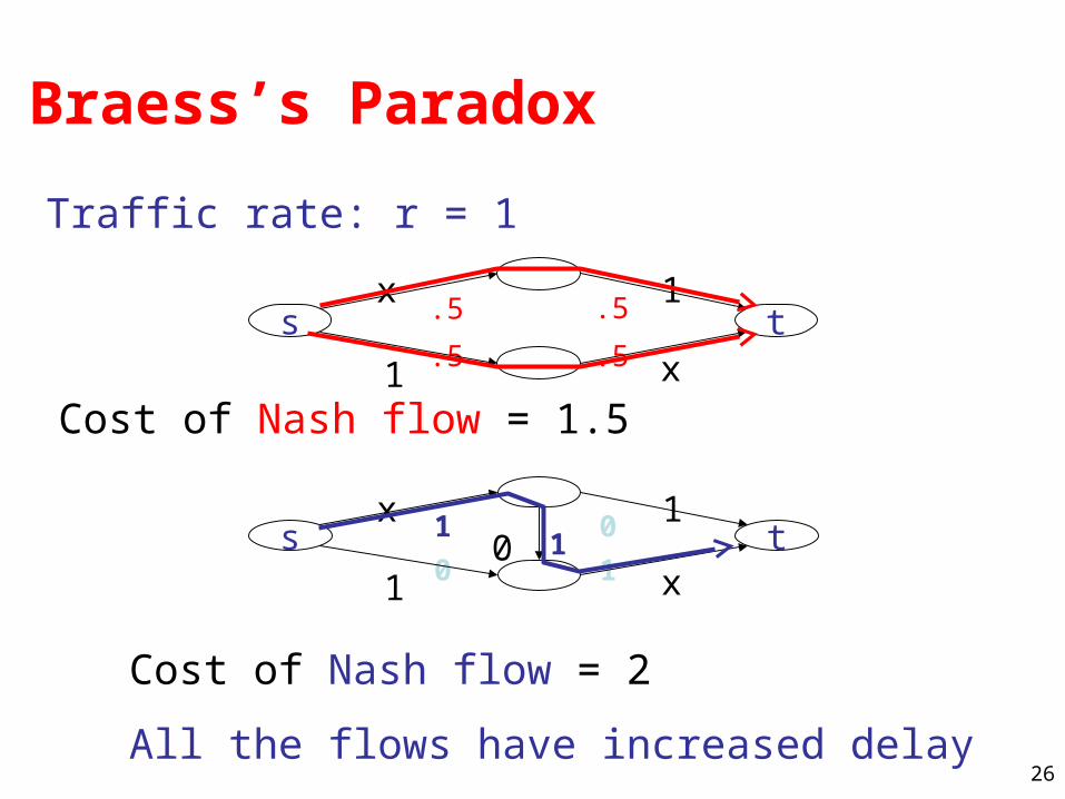
Braess’s Paradox
Traffic rate: r = 1
Cost of Nash flow = 1.5
Cost of Nash flow = 2
All the flows have increased delay
s tx 11
x1 0
0
10 1
s tx 1
.5
x1.5
.5
.5
27
Existing Results and Open Questions
• Theoretical results on bounds of the price of anarchy: 4/3
• Open question: study of the dynamics of this routing game– Will the protocol/overlays actually converge to an
equilibrium, or will they oscillate?
• Current directions: exploring the use of taxation to reduce the cost of selfish routing.
28
Overlays on IP Networks
29
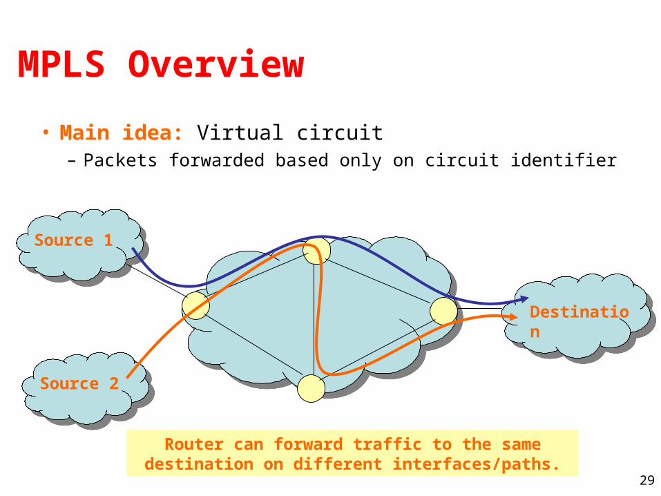
MPLS Overview
• Main idea: Virtual circuit– Packets forwarded based only on circuit identifier
Destination
Source 1
Source 2
Router can forward traffic to the same destination on different interfaces/paths.
30
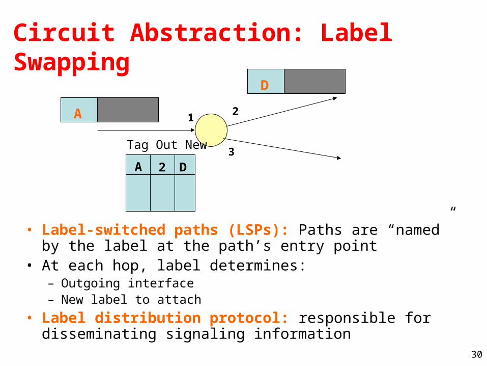
Circuit Abstraction: Label Swapping
• Label-switched paths (LSPs): Paths are “named” by the label at the path’s entry point
• At each hop, label determines:– Outgoing interface– New label to attach
• Label distribution protocol: responsible for disseminating signaling information
A 12
3
A 2 D
Tag Out New
D
31
Layer 3 Virtual Private Networks
• Private communications over a public network
• A set of sites that are allowed to communicate with each other
• Defined by a set of administrative policies
– determine both connectivity and QoS among sites
– established by VPN customers
– One way to implement: BGP/MPLS VPN mechanisms (RFC 2547)
32
Building Private Networks
• Separate physical network– Good security properties– Expensive!
• Secure VPNs– Encryption of entire network stack between endpoints
• Layer 2 Tunneling Protocol (L2TP)– “PPP over IP”– No encryption
• Layer 3 VPNs
Privacy and interconnectivity (not confidentiality, integrity, etc.)
33
Layer 2 vs. Layer 3 VPNs
• Layer 2 VPNs can carry traffic for many different protocols, whereas Layer 3 is “IP only”
• More complicated to provision a Layer 2 VPN
• Layer 3 VPNs: potentially more flexibility, fewer configuration headaches
34
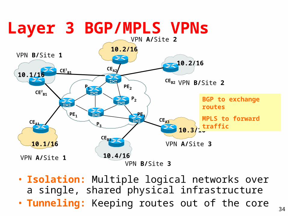
Layer 3 BGP/MPLS VPNs
• Isolation: Multiple logical networks over a single, shared physical infrastructure
• Tunneling: Keeping routes out of the core
VPN A/Site 1
VPN A/Site 2
VPN A/Site 3
VPN B/Site 2
VPN B/Site 1
VPN B/Site 3
CEA1
CEB3
CEA3
CEB2
CEA2CE1B1
CE2B1
PE1
PE2
PE3
P1
P2
P3
10.1/16
10.2/16
10.3/16
10.1/16
10.2/16
10.4/16
BGP to exchange routes
MPLS to forward traffic
35
High-Level Overview of Operation
• IP packets arrive at PE (Provider Edger router)
• Destination IP address is looked up in forwarding table for customer site
• Datagram sent to customer’s network using tunneling (i.e., an MPLS label-switched path)
36
BGP/MPLS VPN key components
• Forwarding in the core: MPLS
• Distributing routes between PEs: BGP
• Isolation: Keeping different VPNs from routing traffic over one another– Constrained distribution of routing information– Multiple “virtual” forwarding tables
• Unique addresses: VPN-IPV4 Address extension (8-byte Route Distinguisher (RD) added to IPV4 address)
37
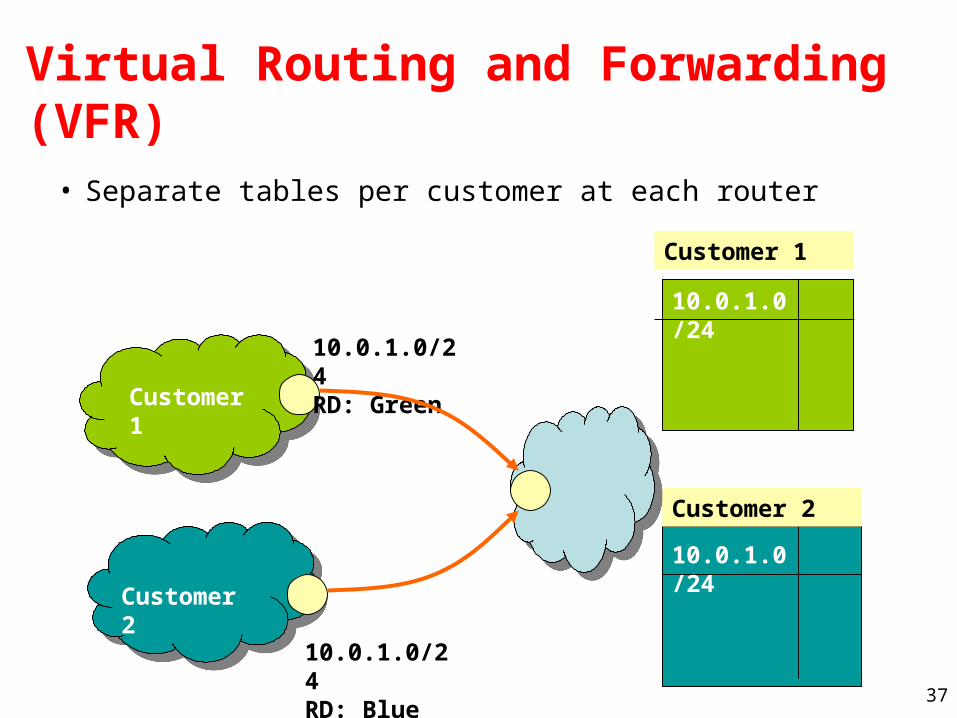
Virtual Routing and Forwarding (VFR)
• Separate tables per customer at each router
10.0.1.0/24RD: Green
10.0.1.0/24RD: Blue
10.0.1.0/24
10.0.1.0/24
Customer 1
Customer 2
Customer 1
Customer 2
38
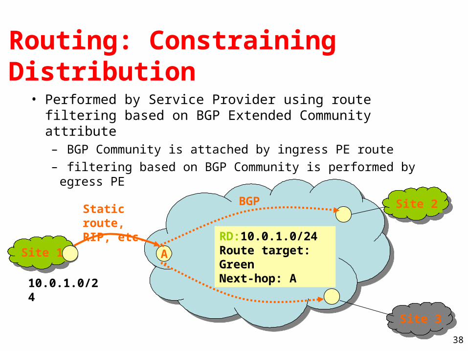
Routing: Constraining Distribution
• Performed by Service Provider using route filtering based on BGP Extended Community attribute– BGP Community is attached by ingress PE route
– filtering based on BGP Community is performed by egress PE
Site 1
Site 2
Site 3
Static route, RIP, etc.
RD:10.0.1.0/24Route target: GreenNext-hop: A
A
10.0.1.0/24
BGP
39
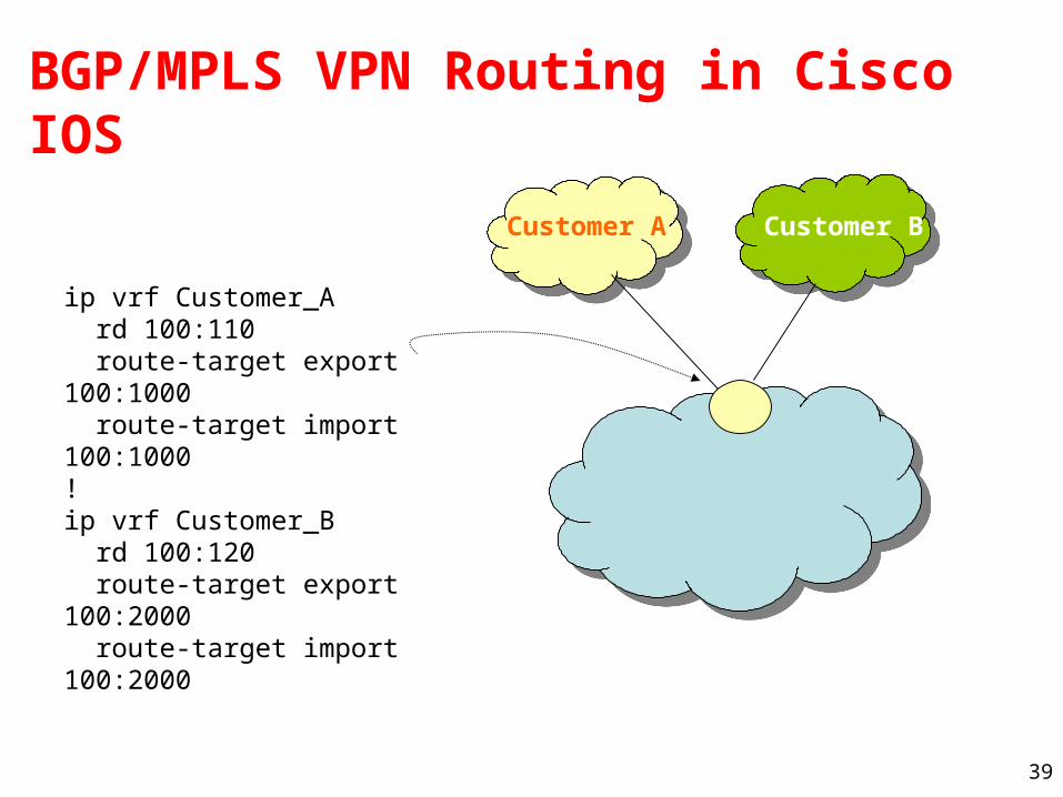
BGP/MPLS VPN Routing in Cisco IOS
ip vrf Customer_A rd 100:110 route-target export 100:1000 route-target import 100:1000 ! ip vrf Customer_B rd 100:120 route-target export 100:2000 route-target import 100:2000
Customer A Customer B
40
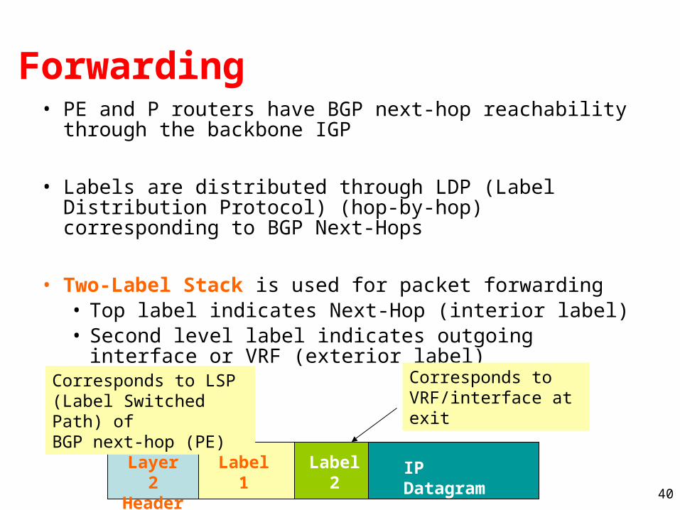
Forwarding• PE and P routers have BGP next-hop reachability
through the backbone IGP
• Labels are distributed through LDP (Label Distribution Protocol) (hop-by-hop) corresponding to BGP Next-Hops
• Two-Label Stack is used for packet forwarding• Top label indicates Next-Hop (interior label)• Second level label indicates outgoing interface or
VRF (exterior label)
IP DatagramLabel2
Label1
Layer 2 Header
Corresponds to LSP (Label Switched Path) ofBGP next-hop (PE)
Corresponds to VRF/interface at exit
41
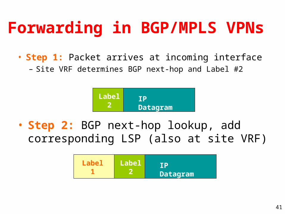
Forwarding in BGP/MPLS VPNs
• Step 1: Packet arrives at incoming interface– Site VRF determines BGP next-hop and Label #2
IP DatagramLabel2
• Step 2: BGP next-hop lookup, add corresponding LSP (also at site VRF)
IP DatagramLabel2
Label1


