20
Connectivity for Business-Critical Continuity Type SMP Connectors Product Catalog
Connectivity forBusiness-Critical Continuity
Type SMP ConnectorsProduct Catalog

2
Connectivity for
Business-Critical ContinuitySMP ConnectorsTable of Content
Table of ContentsPAGE
Introduction . . . . . . . . . . . . . . . . . . . . . . . . . . . . . . . . . . . .3-4
Specifications . . . . . . . . . . . . . . . . . . . . . . . . . . . . . . . . . . .5-8
Mounting Holes . . . . . . . . . . . . . . . . . . . . . . . . . . . . . . . . . . .7
Applications . . . . . . . . . . . . . . . . . . . . . . . . . . . . . . . . . . .9-12
Assembly Tools . . . . . . . . . . . . . . . . . . . . . . . . . . . . . . . . . . .13
Assembly Instructions . . . . . . . . . . . . . . . . . . . . . . . . . .14-18
Competitor Cross Reference . . . . . . . . . . . . . . . . . . . . . . .19

3
Connectivity for
Business-Critical Continuity SMP ConnectorsIntroduction
SMP Blind-Mate ConnectorsEmerson’s new Johnson® line of SMP Blind-Mate Connectors offers our customers a Micro-Miniature,Slide-On/Snap-On Interconnect System that aid’s in the design ofhigh-density packaging as well as axial andradial misalignment issues.
The SMP Interface offers superior performance up to 40 GHz and is compatible with all SMP and GPO®
Connectors. They offer high electrical reliability where extreme shock and vibration condition’s are experienced.
Applications (Military and Commercial)
• Phased Arrays • Active Antennas • Satellites
• Communication • Airborne Radar •Shipborne RadarEquipment
•Ground Radar • Hi-Density Modular • Axial/ RadialPackaging Misalignment
Solutions
Markets
• Aerospace • Broadband • Instrumentation
• Telecom • Defense • Microwave
Transmission Options
• Box-to-Box• Cable-to-Board• Board-to-Board• Cable-to-Panel-to-Board
*GPO® is a registered trademark of Corning Gilbert.

4
Connectivity for
Business-Critical ContinuitySMP ConnectorsIntroduction
Description
One of the key benefits of the SMP connector interface is its use in high frequency blind-mate applications. Thedesign of the SMP bullet and shroud system allows for both axial and radial misalignment. The basic system iscomprised of an inner “bullet” adapter, and two outer receptacles called “shrouds”. The bullet provides aflexible link between the shroud connections.
In blind-mate applications, one shroud connector will be typically specified as a snap-on interface and the otheras a slide-on. This ensures that the bullet adapter remains fixed in the same shroud connector when theconnection is disengaged.
The two snap-on interfaces Full Detent (FD) and Limited Detent (LD) each have different engage and disengagecoupling forces. The LD is typically selected as the snap-on interface in PCB mount or blind-mate applications,while the FD is mainly used for cabled connections where higher retention forces are required.
The two slide-on interfaces Smooth Bore (SM) and Catcher’s Mit (CM) allow for reduced connection forces ascompared to the snap-on versions. The push-on interface creates a sliding connection that does not physicallylocate the mating reference planes, allowing for axial and radial misalignment. Both the SM and CM have thesame engage/disengage forces; however the CM is typically specified as the shroud configuration in blind-mateapplications as its generous lead-in chamfer helps capture and guide the bullet into place.
Bullet Length
Radial Misalignment
Axial Misalignment
Shroud
5
Connectivity for
Business-Critical Continuity SMP ConnectorsSpecifications
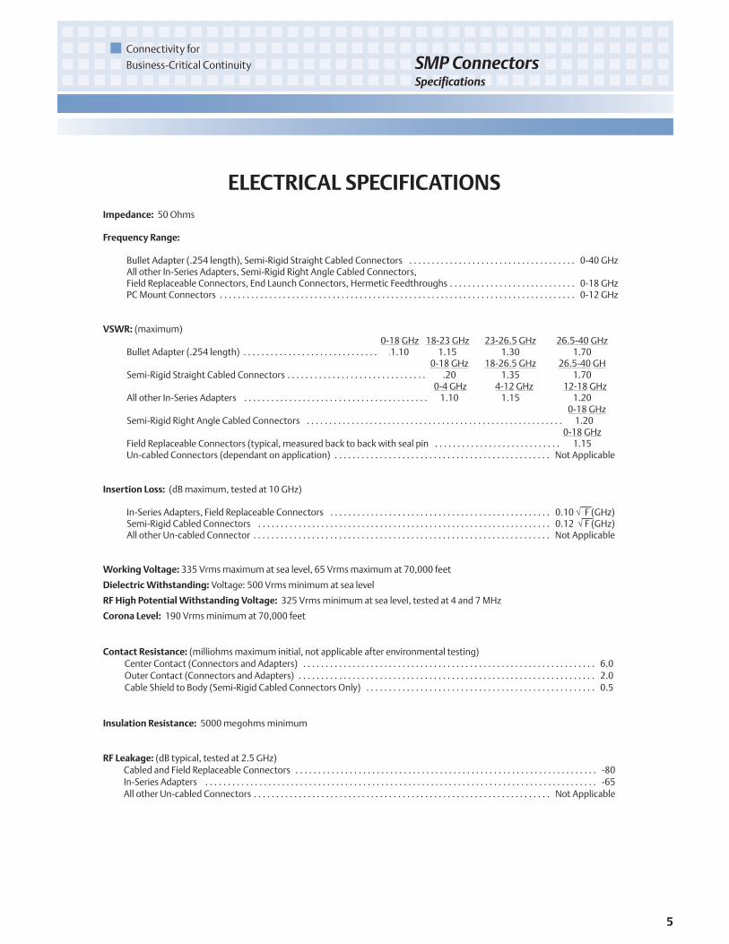
ELECTRICAL SPECIFICATIONSImpedance: 50 Ohms
Frequency Range:
Bullet Adapter (.254 length), Semi-Rigid Straight Cabled Connectors . . . . . . . . . . . . . . . . . . . . . . . . . . . . . . . . . . . . . 0-40 GHzAll other In-Series Adapters, Semi-Rigid Right Angle Cabled Connectors,Field Replaceable Connectors, End Launch Connectors, Hermetic Feedthroughs . . . . . . . . . . . . . . . . . . . . . . . . . . . . 0-18 GHzPC Mount Connectors . . . . . . . . . . . . . . . . . . . . . . . . . . . . . . . . . . . . . . . . . . . . . . . . . . . . . . . . . . . . . . . . . . . . . . . . . . . . . . . 0-12 GHz
VSWR: (maximum)0-18 GHz 18-23 GHz 23-26.5 GHz 26.5-40 GHz
Bullet Adapter (.254 length) . . . . . . . . . . . . . . . . . . . . . . . . . . . . . . . . .1.10 1.15 1.30 1.700-18 GHz 18-26.5 GHz 26.5-40 GH
Semi-Rigid Straight Cabled Connectors . . . . . . . . . . . . . . . . . . . . . . . . . . . . . . . . . . .20 1.35 1.700-4 GHz 4-12 GHz 12-18 GHz
All other In-Series Adapters . . . . . . . . . . . . . . . . . . . . . . . . . . . . . . . . . . . . . . . . . . . 1.10 1.15 1.200-18 GHz
Semi-Rigid Right Angle Cabled Connectors . . . . . . . . . . . . . . . . . . . . . . . . . . . . . . . . . . . . . . . . . . . . . . . . . . . . . . . . . . . 1.200-18 GHz
Field Replaceable Connectors (typical, measured back to back with seal pin . . . . . . . . . . . . . . . . . . . . . . . . . . . . . . .1.15Un-cabled Connectors (dependant on application) . . . . . . . . . . . . . . . . . . . . . . . . . . . . . . . . . . . . . . . . . . . . . . . . Not Applicable
Insertion Loss: (dB maximum, tested at 10 GHz)
In-Series Adapters, Field Replaceable Connectors . . . . . . . . . . . . . . . . . . . . . . . . . . . . . . . . . . . . . . . . . . . . . . . . . 0.10 √ F (GHz)Semi-Rigid Cabled Connectors . . . . . . . . . . . . . . . . . . . . . . . . . . . . . . . . . . . . . . . . . . . . . . . . . . . . . . . . . . . . . . . . . 0.12 √ F (GHz)All other Un-cabled Connector . . . . . . . . . . . . . . . . . . . . . . . . . . . . . . . . . . . . . . . . . . . . . . . . . . . . . . . . . . . . . . . . . . Not Applicable
Working Voltage: 335 Vrms maximum at sea level, 65 Vrms maximum at 70,000 feet
DielectricWithstanding: Voltage: 500 Vrms minimum at sea level
RF High PotentialWithstanding Voltage: 325 Vrms minimum at sea level, tested at 4 and 7 MHz
Corona Level: 190 Vrms minimum at 70,000 feet
Contact Resistance: (milliohms maximum initial, not applicable after environmental testing)Center Contact (Connectors and Adapters) . . . . . . . . . . . . . . . . . . . . . . . . . . . . . . . . . . . . . . . . . . . . . . . . . . . . . . . . . . . . . . . . . 6.0Outer Contact (Connectors and Adapters) . . . . . . . . . . . . . . . . . . . . . . . . . . . . . . . . . . . . . . . . . . . . . . . . . . . . . . . . . . . . . . . . . . 2.0Cable Shield to Body (Semi-Rigid Cabled Connectors Only) . . . . . . . . . . . . . . . . . . . . . . . . . . . . . . . . . . . . . . . . . . . . . . . . . . . 0.5
Insulation Resistance: 5000 megohms minimum
RF Leakage: (dB typical, tested at 2.5 GHz)Cabled and Field Replaceable Connectors . . . . . . . . . . . . . . . . . . . . . . . . . . . . . . . . . . . . . . . . . . . . . . . . . . . . . . . . . . . . . . . . . . . -80In-Series Adapters . . . . . . . . . . . . . . . . . . . . . . . . . . . . . . . . . . . . . . . . . . . . . . . . . . . . . . . . . . . . . . . . . . . . . . . . . . . . . . . . . . . . . . . -65All other Un-cabled Connectors . . . . . . . . . . . . . . . . . . . . . . . . . . . . . . . . . . . . . . . . . . . . . . . . . . . . . . . . . . . . . . . . . . Not Applicable

6
Connectivity for
Business-Critical ContinuitySMP ConnectorsSpecifications
MECHANICAL SPECIFICATIONSInterface Design: MIL-STD-348A, Series SMP
Engagement Force: (pounds maximum, mated pair)Full Detent (FD) . . . . . . . . . . . . . . . . . . . . . . . . . . . . . . . . . . . . . . . . . . . . . . . . . . . . . . . . . . . . . . . . . . . . . . . . . . . . . . . . . . . . . . . . . 15.0Limited Detent (LD) . . . . . . . . . . . . . . . . . . . . . . . . . . . . . . . . . . . . . . . . . . . . . . . . . . . . . . . . . . . . . . . . . . . . . . . . . . . . . . . . . . . . . 10.0Smooth Bore and Catcher’s Mit (SM and CM) . . . . . . . . . . . . . . . . . . . . . . . . . . . . . . . . . . . . . . . . . . . . . . . . . . . . . . . . . . . . . . . 2.0
Disengagement Force: (pounds minimum, mated pair)Full Detent (FD) . . . . . . . . . . . . . . . . . . . . . . . . . . . . . . . . . . . . . . . . . . . . . . . . . . . . . . . . . . . . . . . . . . . . . . . . . . . . . . . . . . . . . . . . . . 5.0Limited Detent (LD) . . . . . . . . . . . . . . . . . . . . . . . . . . . . . . . . . . . . . . . . . . . . . . . . . . . . . . . . . . . . . . . . . . . . . . . . . . . . . . . . . . . . . . 2.0Smooth Bore and Catcher’s Mit (SM and CM) . . . . . . . . . . . . . . . . . . . . . . . . . . . . . . . . . . . . . . . . . . . . . . . . . . . . . . . . . . . . . . . . 0.5
Mated Radial Misalignment: (inches maximum allowed, female adapters only)Between Centerlines of Mating Planes (FD, LD, SM) . . . . . . . . . . . . . . . . . . . . . . . . . . . . . . . . . . . . . . . . . . . . . . . . . . . . . . . . . . .010Between Centerlines of Mating Planes (CM only) . . . . . . . . . . . . . . . . . . . . . . . . . . . . . . . . . . . . . . . . . . . . . . . . . . . . . . . . . . . . .020
Mated Axial Misalignment: .010 inches maximum allowed between mating planes (female adapters only)
Durability: (mating cycles minimum)Full Detent (all female connectors and adapters) . . . . . . . . . . . . . . . . . . . . . . . . . . . . . . . . . . . . . . . . . . . . . . . . . . . . . . . . . . . . 100Limited Detent (female adapters only) . . . . . . . . . . . . . . . . . . . . . . . . . . . . . . . . . . . . . . . . . . . . . . . . . . . . . . . . . . . . . . . . . . . . 500Smooth Bore and Catcher’s Mit (female adapters only) . . . . . . . . . . . . . . . . . . . . . . . . . . . . . . . . . . . . . . . . . . . . . . . . . . . . . . 1000
Contact Retention: 1.5 pounds minimum axial force (captivated contacts only)
Cable Retention: (minimum)Axial Force* (lbs) Torque (in-oz)
Cabled Connectors for RG-405 (.086 Semi-Rigid) . . . . . . . . . . . . . . . . . . . . . . . . . . . . . . . . . . . . . . . 30 16.0Cabled Connectors for M17/151 (.047 Semi-Rigid) . . . . . . . . . . . . . . . . . . . . . . . . . . . . . . . . . . . . . 20 N/A
*Or cable breaking strength, whichever is less
0 5 10 15 20 25 30 35 40
0
-10
-20
-30
-40
-50
-60
Frequency (GHz)
S11
(dB)
Typical Measured Return LossBullet Adapter 127-0901-801
127-0801-901 VSWR = 1.10 (0-18 GHz), 1.15 (18-23 GHz), 1.30 (23-26.5 GHz), 1.70 (26.5-40 GHz)

7
Connectivity for
Business-Critical Continuity SMP ConnectorsSpecifications
ENVIRONMENTAL SPECIFICATIONS(Meets or Exceeds the Applicable Paragraph of MIL-PRF-39012)
Operating Temperature: -65°C to +165°C
Thermal Shock: MIL-STD-202, Method 107, Condition B (except high temp +165°C or max high temp of cable)
Corrosion: MIL-STD-202, Method 101, Condition B
Shock (specified pulse): MIL-STD-202, Method 213, Condition I
Vibration: MIL-STD-202, Method 204, Condition D
Moisture Resistance: MIL-STD-202, Method 106 (except step 7b omitted)
MATERIAL SPECIFICATIONSSpring Finger (female) and End Launch (male) Bodies: Beryllium Copper per ASTM B196,
Gold* plated per MIL-DTL-45204 (.00005” min)Hermetic Seal Bodies (male): Kovar Alloy per ASTM F15, Gold* plated per MIL-DTL-45204 (.00005” min)All other Shroud Bodies (male): Stainless Steel, Type 303, per ASTM A582, Passivated per MIL-DTL-14072 (EL 300)Connector and Adapter Contacts (male and female): Beryllium Copper per ASTM B196,
Gold* plated per MIL-DTL-45204 (.00005” min)Hermetic Seal Center Pins: Kovar Alloy per ASTM F15, Gold* plated per MIL-DTL-45204 (.00005” min)EMI/Anti-Rock Rings: Beryllium Copper per ASTM B196, Gold* plated per MIL-DTL-45204 (.00003” min)PCMount Legs: Brass per ASTM B16, Gold* plated per MIL-DTL-45204 (.00003” min)Connector and Adapter Insulators: PTFE per ASTM D1710Hermetic Seal Glass: Corning 7070
*All gold plated parts include a .00005” min nickel barrier layer.
MOUNTINGHOLES
Fig 1
This pattern is for reference only.Pattern will vary depending on boardtype and specific electrical andmechanical requirements.
Fig 2 Fig 3

8
Connectivity for
Business-Critical ContinuitySMP ConnectorsSpecifications
Mating Engagement for SMPSeries perMIL-STD-348A
Notes:
1. Socket to accept mating pin Ø.015±.001 (0.38±0.03).2. EMI/Anti-Rock Ring configuration optional, used on cabled connectors only. Shall not prevent proper mating engagement.3. All dimensions shown in inches. Metric equivalents (rounded to nearest 0.01mm) are given for general information only.
Dimension Full Detent Limited Detent Smooth Bore Catcher’s MitMinimum Maximum Minimum Maximum Minimum Maximum Minimum Maximum
B .051 (1.30) .057 (1.45) .054 (1.37) .060 (1.52) .059 (1.50) .065 (1.65) N/A N/AC .0205 (0.52) .0235 (0.60) .0205 (0.52) .0235 (0.60) N/A N/A N/A N/AD .003 (0.08) .008 (0.20) .003 (0.08) .008 (0.20) .003 (0.08) .008 (0.20) .043 (1.09) .047 (1.19)E .033 (0.84) .037 (0.94) .033 (0.84) .037 (0.94) .033 (0.84) .037 (0.94) N/A N/AF .139 (3.53) .145 (3.68) .139 (3.53) .145 (3.68) .139 (3.53) .145 (3.68) .123 (3.12) .127 (3.23)G .114 (2.90) .118 (3.00) .118 (3.00) .122 (3.10) .123 (3.12) .127 (3.23) N/A N/AH .124 (3.15) .126 (3.20) .124 (3.15) .126 (3.20) N/A N/A N/A N/AK 35° REF 35° REF 35° REF 35° REF 35° REF 35° REF N/A N/AM 30° REF 30° REF 30° REF 30° REF N/A N/A N/A N/A
Dimension Cabled UncabledMinimum Maximum Minimum Maximum
A .025 (0.64) .035 (0.89) .018 (0.46) .025 (0.64)
SMPFemale Connector Interface
SMPMale Connector Interface
9
Connectivity for
Business-Critical Continuity SMP ConnectorsApplication
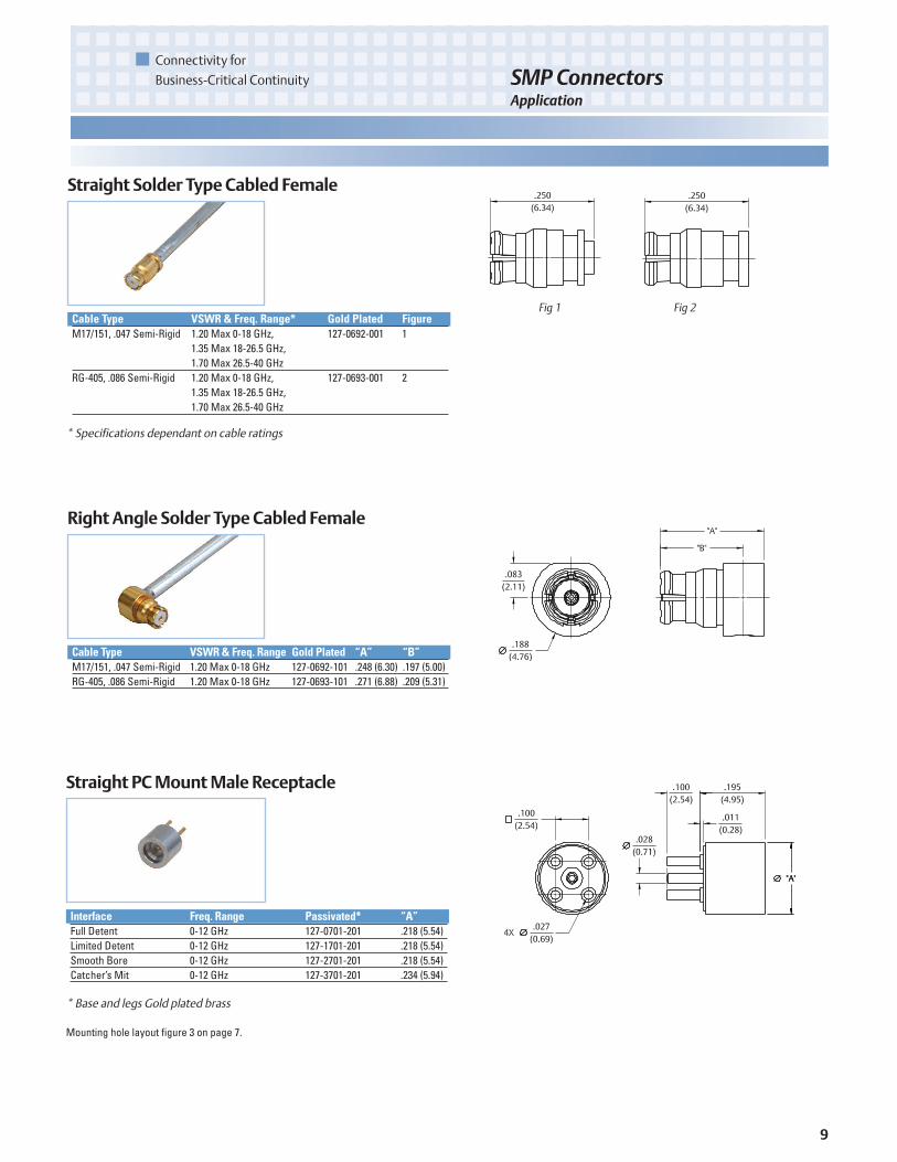
Straight Solder TypeCabled Female
Cable Type VSWR & Freq. Range* Gold Plated FigureM17/151, .047 Semi-Rigid 1.20 Max 0-18 GHz, 127-0692-001 1
1.35 Max 18-26.5 GHz,1.70 Max 26.5-40 GHz
RG-405, .086 Semi-Rigid 1.20 Max 0-18 GHz, 127-0693-001 21.35 Max 18-26.5 GHz,1.70 Max 26.5-40 GHz
* Specifications dependant on cable ratings
RightAngle Solder TypeCabled Female
Cable Type VSWR& Freq. Range Gold Plated “A” “B”M17/151, .047 Semi-Rigid 1.20 Max 0-18 GHz 127-0692-101 .248 (6.30) .197 (5.00)RG-405, .086 Semi-Rigid 1.20 Max 0-18 GHz 127-0693-101 .271 (6.88) .209 (5.31)
Fig 1 Fig 2
Straight PCMountMale Receptacle
Interface Freq. Range Passivated* “A”Full Detent 0-12 GHz 127-0701-201 .218 (5.54)Limited Detent 0-12 GHz 127-1701-201 .218 (5.54)Smooth Bore 0-12 GHz 127-2701-201 .218 (5.54)Catcher’s Mit 0-12 GHz 127-3701-201 .234 (5.94)
* Base and legs Gold plated brass
Mounting hole layout figure 3 on page 7.
10
Connectivity for
Business-Critical ContinuitySMP ConnectorsApplication
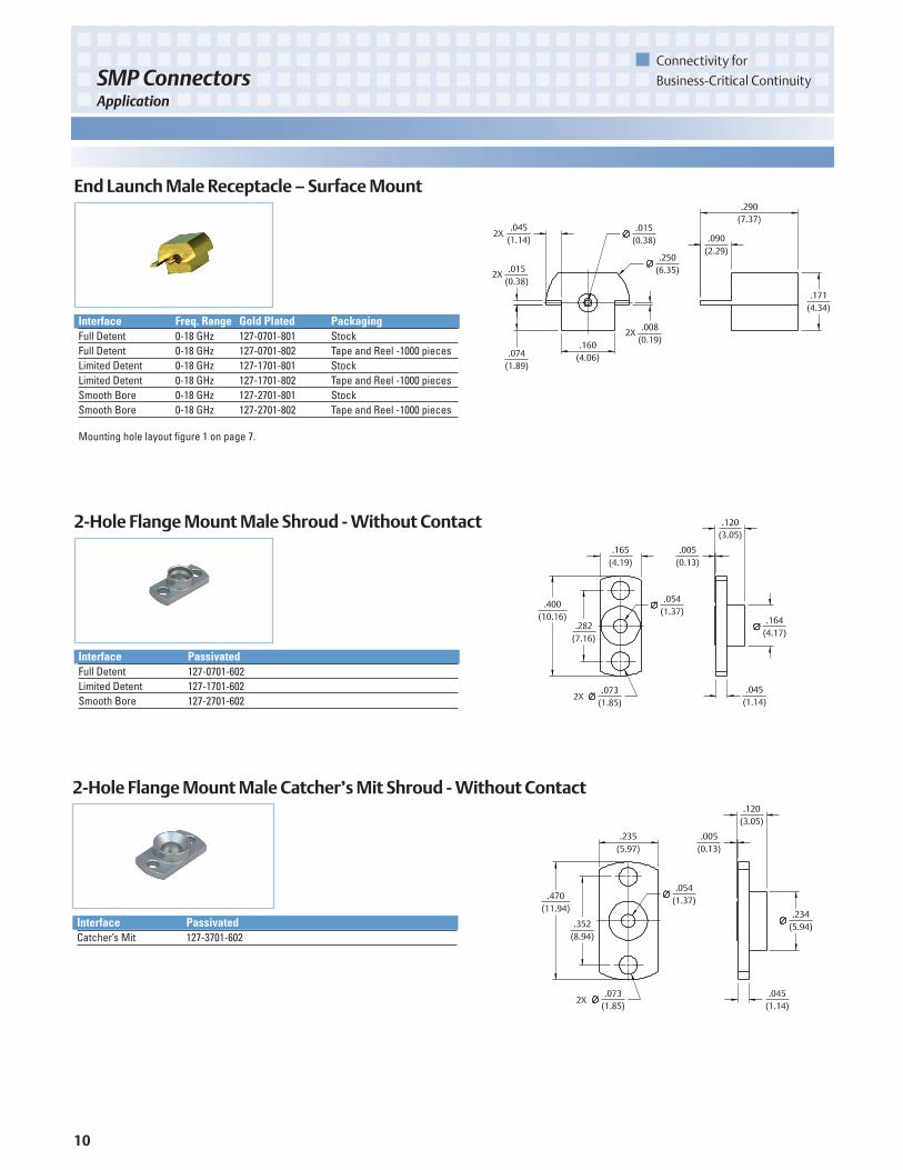
End LaunchMale Receptacle – SurfaceMount
Interface Freq. Range Gold Plated PackagingFull Detent 0-18 GHz 127-0701-801 StockFull Detent 0-18 GHz 127-0701-802 Tape and Reel -1000 piecesLimited Detent 0-18 GHz 127-1701-801 StockLimited Detent 0-18 GHz 127-1701-802 Tape and Reel -1000 piecesSmooth Bore 0-18 GHz 127-2701-801 StockSmooth Bore 0-18 GHz 127-2701-802 Tape and Reel -1000 pieces
Mounting hole layout figure 1 on page 7.
2-Hole FlangeMountMale Shroud -Without Contact
Interface PassivatedFull Detent 127-0701-602Limited Detent 127-1701-602Smooth Bore 127-2701-602
2-Hole FlangeMountMale Catcher’sMit Shroud -Without Contact
Interface PassivatedCatcher’s Mit 127-3701-602
11
Connectivity for
Business-Critical Continuity SMP ConnectorsApplication
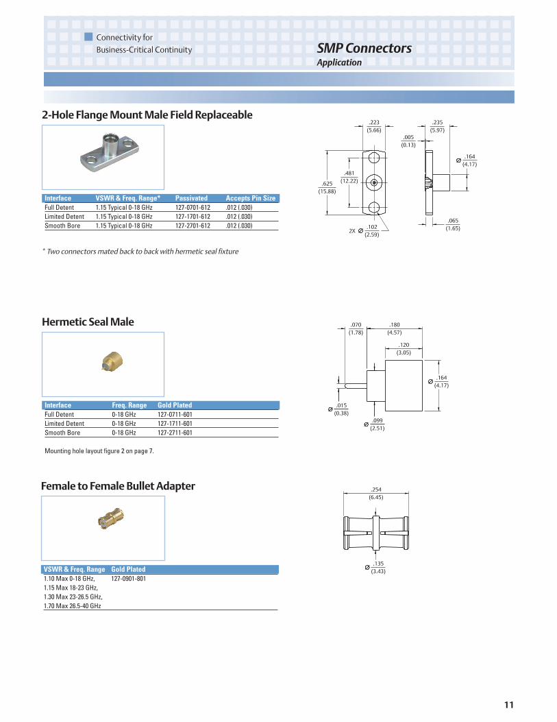
2-Hole FlangeMountMale Field Replaceable
Interface VSWR & Freq. Range* Passivated Accepts Pin SizeFull Detent 1.15 Typical 0-18 GHz 127-0701-612 .012 (.030)Limited Detent 1.15 Typical 0-18 GHz 127-1701-612 .012 (.030)Smooth Bore 1.15 Typical 0-18 GHz 127-2701-612 .012 (.030)
* Two connectors mated back to back with hermetic seal fixture
Hermetic SealMale
Interface Freq. Range Gold PlatedFull Detent 0-18 GHz 127-0711-601Limited Detent 0-18 GHz 127-1711-601Smooth Bore 0-18 GHz 127-2711-601
Mounting hole layout figure 2 on page 7.
Female to Female Bullet Adapter
VSWR & Freq. Range Gold Plated1.10 Max 0-18 GHz, 127-0901-8011.15 Max 18-23 GHz,1.30 Max 23-26.5 GHz,1.70 Max 26.5-40 GHz

12
Connectivity for
Business-Critical ContinuitySMP ConnectorsApplication
Female to FemaleAdapter
VSWR & Freq. Range Gold Plated1.10 Max 0-4 GHz, 127-0901-8111.15 Max 4-12 GHz,1.20 Max 12-18 GHz
Male toMale Catcher’sMit Adapter
Interface VSWR & Freq. Range PassivatedFull Detent 1.10 Max 0-4 GHz, 127-0901-821
1.15 Max 4-12 GHz,1.20 Max 12-18 GHz
Limited Detent 1.10 Max 0-4 GHz, 127-1901-8211.15 Max 4-12 GHz,1.20 Max 12-18 GHz
Smooth Bore 1.10 Max 0-4 GHz, 127-2901-8211.15 Max 4-12 GHz,1.20 Max 12-18 GHz

13
Connectivity for
Business-Critical Continuity SMP ConnectorsAssembly Tools
Item Description Part NumberA SMP Bullet Extraction Tool 127-0000-900B SMP Cabled Connector Removal Tool 127-0000-901C Soldering Vise (does not include clamp inserts or stop screw) 140-0000-962D Stop Screw for Soldering Vise 140-0000-981E Semi-Rigid Cable Clamp Inserts for .086" OD Cable 140-0000-964
Semi-Rigid Cable Clamp Inserts for .047" OD Cable 140-0000-997F Solder Shim for .086" OD Cable 140-0000-984G SMP Center Contact Holder 127-0000-902H SMP Interface Locator Tool 127-0000-903I SMP Right Angle Body Holder 127-0000-904J SMP FD Shroud Centering Tool 127-0000-905
SMP LD Shroud Centering Tool 127-0000-906SMP SB Shroud Centering Tool 127-0000-907
SMP Customer ToolingAccurate assembly of the Semi-Rigid Cabled Connectors is obtained with the tools listed below. Industry standard devices are used if possible forcustomer convenience and tool compatibility.
A.
B.
C.
E.
F.
H.
D. G.
J.I.

14
Connectivity for
Business-Critical ContinuitySMP ConnectorsAssembly Instructions
Tool Part NumberCable Vise 140-0000-962Stop Screw 140-0000-981Clamp Inserts 140-0000-997Contact Holder 127-0000-902Interface Location Fixture 127-0000-903
ASSEMBLY INSTRUCTIONS
Cable Group Part NumberMIL-C-17/151, .047 Semi-Rigid 127-0692-001
SMPStraight Female Solder Style for .047 OD Semi-Rigid Cable
1 Identify tools (5 piece parts) and connector parts (3 piece parts).2. Strip cable jacket and dielectric to dimension shown. Do not
nick center conductor. Clean all debris from prepared cable.3. Insert center conductor into cable stop as shown and place
contact onto center conductor.4. Insert contact into contact holder fixture and clamp cable in vise.
Tighten stop screw until light pressure is applied between con-tact, cable stop and cable jacket.
5. Solder contact to center conductor through solder hole using.016 (0.41) diameter flux core solder wire or solder paste. Use aminimum amount of solder and heat for a good joint. Do notallow heat to build up for a long period of time as cable stopmay melt.
6. After solder joint has cooled, remove cable from vise. Removeany excess solder from contact with a sharp blade and clean alldebris from contact and cable.
7. Insert contact into connector assembly, making sure cable stopbottoms out against internal shoulder of connector body. Insertconnector assembly into interface location fixture and clampcable in vise. Make sure connector assembly is fully engagedwithin location fixture. Tighten stop screw until light pressure isapplied between connector assembly and cable stop.
8. Solder end of connector body to cable jacket, using a minimumamount of solder and heat for a full fillet joint. Allow assembly tocool before removing connector from vise and location fixture.Best results are obtained when contact location is flush to .004(0.10) recessed from reference plane. Interface location fixtureis pre-set at factory, but can be adjusted to control location.

15
Connectivity for
Business-Critical Continuity SMP ConnectorsAssembly Instructions
Tool Part NumberCable Vise 140-0000-962Stop Screw 140-0000-981Clamp Inserts 140-0000-997Body Holder 127-0000-904Interface Location Fixture 127-0000-903
Cable Group Part NumberMIL-C-17/151, .047 Semi-Rigid 127-0692-101
SMPRight Angle Female Solder Style for .047 OD Semi-Rigid Cable
1. Identify tools (5 piece parts) and connector parts (3 piece parts).2. Strip cable jacket and dielectric to dimension shown. Do not
nick center conductor. Clean all debris from prepared cable.3. Insert center conductor into cable stop as shown. Make sure
slot in connector contact is aligned with cross hole in body asshown. Insert cable into cross hole in connector body, makingsure cable stop bottoms out against internal shoulder ofconnector body.
4. Insert connector assembly into interface location fixture andclamp cable in vise using body holder fixture as shown. Tightenstop screw until light pressure is applied between connectorbody, cable stop and cable jacket.
5. Solder contact to center conductor through rear access port inconnector body using a minimum amount of solder and heat for agood joint.
6. After center conductor solder joint has cooled, solder connectorbody to cable jacket, using a minimum amount of solder and heatfor a full fillet joint. Take care so that solder does not flow ontoanti-rock ring or into rear access port. Allow assembly to coolbefore removing connector from vise and location fixture.
7. Using a fixture plate as shown, press end cap into rear accessport using a .156 (3.96) diameter flat punch until fully seatedwithin body counter bore.
8. Best results are obtained when contact location is flush to .004(0.10) recessed from reference plane. Interface location fixtureis pre-set at factory, but can be adjusted to control location.
16
Connectivity for
Business-Critical ContinuitySMP ConnectorsAssembly Instructions
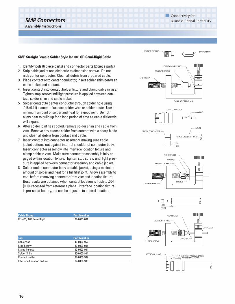
Tool Part NumberCable Vise 140-0000-962Stop Screw 140-0000-981Clamp Inserts 140-0000-964Solder Shim 140-0000-984Contact Holder 127-0000-902Interface Location Fixture 127-0000-903
Cable Group Part NumberRG-405, .086 Semi-Rigid 127-0693-001
SMPStraight Female Solder Style for .086 OD Semi-Rigid Cable
1. Identify tools (6 piece parts) and connector parts (2 piece parts).2. Strip cable jacket and dielectric to dimension shown. Do not
nick center conductor. Clean all debris from prepared cable.3. Place contact onto center conductor, insert solder shim between
cable jacket and contact.4. Insert contact into contact holder fixture and clamp cable in vise.
Tighten stop screw until light pressure is applied between con-tact, solder shim and cable jacket.
5. Solder contact to center conductor through solder hole using.016 (0.41) diameter flux core solder wire or solder paste. Use aminimum amount of solder and heat for a good joint. Do notallow heat to build up for a long period of time as cable dielectricwill expand.
6. After solder joint has cooled, remove solder shim and cable fromvise. Remove any excess solder from contact with a sharp bladeand clean all debris from contact and cable.
7. Insert contact into connector assembly, making sure cablejacket bottoms out against internal shoulder of connector body.Insert connector assembly into interface location fixture andclamp cable in vise. Make sure connector assembly is fully en-gaged within location fixture. Tighten stop screw until light pres-sure is applied between connector assembly and cable jacket.
8. Solder end of connector body to cable jacket, using a minimumamount of solder and heat for a full fillet joint. Allow assembly tocool before removing connector from vise and location fixture.Best results are obtained when contact location is flush to .004(0.10) recessed from reference plane. Interface location fixtureis pre-set at factory, but can be adjusted to control location.
17
Connectivity for
Business-Critical Continuity SMP ConnectorsAssembly Instructions
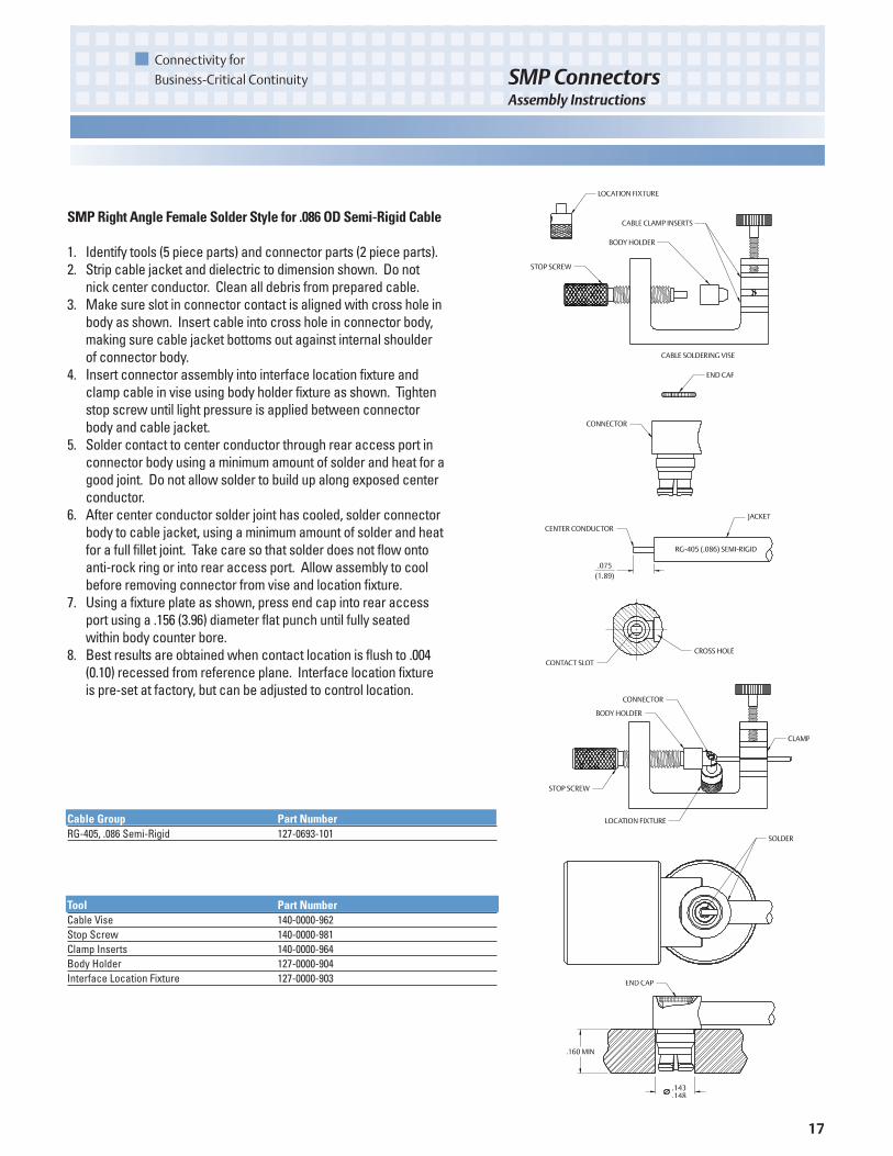
Tool Part NumberCable Vise 140-0000-962Stop Screw 140-0000-981Clamp Inserts 140-0000-964Body Holder 127-0000-904Interface Location Fixture 127-0000-903
Cable Group Part NumberRG-405, .086 Semi-Rigid 127-0693-101
SMPRight Angle Female Solder Style for .086 OD Semi-Rigid Cable
1. Identify tools (5 piece parts) and connector parts (2 piece parts).2. Strip cable jacket and dielectric to dimension shown. Do not
nick center conductor. Clean all debris from prepared cable.3. Make sure slot in connector contact is aligned with cross hole in
body as shown. Insert cable into cross hole in connector body,making sure cable jacket bottoms out against internal shoulderof connector body.
4. Insert connector assembly into interface location fixture andclamp cable in vise using body holder fixture as shown. Tightenstop screw until light pressure is applied between connectorbody and cable jacket.
5. Solder contact to center conductor through rear access port inconnector body using a minimum amount of solder and heat for agood joint. Do not allow solder to build up along exposed centerconductor.
6. After center conductor solder joint has cooled, solder connectorbody to cable jacket, using a minimum amount of solder and heatfor a full fillet joint. Take care so that solder does not flow ontoanti-rock ring or into rear access port. Allow assembly to coolbefore removing connector from vise and location fixture.
7. Using a fixture plate as shown, press end cap into rear accessport using a .156 (3.96) diameter flat punch until fully seatedwithin body counter bore.
8. Best results are obtained when contact location is flush to .004(0.10) recessed from reference plane. Interface location fixtureis pre-set at factory, but can be adjusted to control location.

18
Connectivity for
Business-Critical ContinuitySMP ConnectorsAssembly Instructions
Interface Part NumberFull Detent 127-0711-601Limited Detent 127-1711-601Smooth Bore 127-2711-601
SMPHermetic Seal Installation
1. Prepare housing panel per figure 2 as shown on page 7.2. Install solder ring on hermetic seal as shown. Recommended
ring size is .103 (2.62) ID x .128 (3.25) OD x .015 (0.38) Thick.3. Solder in place as shown.
Shroud Part Number Tool Part Number127-0701-602 127-0000-905127-1701-602 127-0000-906127-2701-602 127-0000-907127-3701-602 127-0000-907
SMPShroud Installation
1. Install appropriate assembly tool into shroud as shown.2. While holding tool in place, align flange mount with mounting
holes in panel. Install fasteners and torque to 6-8 in/lbs.

19
Connectivity for
Business-Critical Continuity SMP ConnectorsCross Reference
Description Johnson Tensolite Corning Gilbert Micro-Mode SVMicrowave AEP RosenbergerStraight Female M17/151 (.047 SR) Cabled 127-0692-001 P651-1CC A014-B11-01 MMSP-6120 1203-4000 7500-1582-011 19K101-270E4Straight Female RG 405 (.086 SR) Cabled 127-0693-001 P651-2CC A014-D11-01 MMSP-2508 1204-4000 7500-1562-010 19K101-271E4Right Angle Female M17/151 (.047 SR) Cabled 127-0692-101 P652-1CC A015-B11-01 MMSP-6968 1213-4006 7501-1562-011 19K202-270E4Right Angle Female RG 405 (.086 SR) Cabled 127-0693-101 P652-2CC A015-D11-01 MMSP-2598 1214-4001 7501-1562-010 19K202-271E4Field Replaceable .012 Socket 2 Hole Flange Male FD 127-0701-612 P836-4CCF SF1250-6000Field Replaceable .012 Socket 2 Hole Flange Male LD 127-1701-612 P836-5CCFField Replaceable .012 Socket 2 Hole Flange Male SB 127-2701-612 P836-6CCFAdapter Bullet Female/Female .254 127-0901-801 P650-1CC A1A1-0001-01 MMSP-2500 1290-4004 5280-1502-000 19K101-K00E4Adapter Female/Female .769 127-0901-811 P617-1CC MMSP-3829 1290-4007 5280-1502-001 19K115-K00E4Adapter Male CM/Male FD 127-0901-822 P912-1CCSF A3A6-0539-01Adapter Male CM/Male LD 127-1901-822 P912-2CCSFAdapter Male CM/Male SB 127-2901-822 P912-3CCSF SF1293-6004Shroud 2 Hole Flange .165 Wide x .400 High FD 127-0701-602 P670-3SF A001-A23-04 MMSP-2514 SF1254-6006Shroud 2 Hole Flange .165 Wide x .400 High LD 127-1701-602 P672-3SF A001-A24-04 MMSP-6095 SF1254-6007Shroud 2 Hole Flange .165 Wide x .400 High SB 127-2701-602 P673-3SF A001-A25-04 MMSP-6067 SF1254-6008Shroud 2 Hole Flange .235 Wide x .470 High CM 127-3701-602 P671-1SFPC Mount Straight .218 OD .100 Legs Male FD 127-0701-201 P654-5CC A008-L33-01 MMSP-7448 SF1287-6001PC Mount Straight .218 OD .100 Legs Male LD 127-1701-201 P654-6CC A008-L34-01 MMSP-7449PC Mount Straight .218 OD .100 Legs Male SB 127-2701-201 P654-7CC A008-L35-01PC Mount Straight .235 OD .100 Legs Male CM 127-3701-201 P654-8CCEnd Launch Surface Mount Male FD 127-0701-801 P606-1CC A010-L13-02 MMSP-7457End Launch Surface Mount Male LD 127-1701-801 P606-2CC A010-L14-02 MMSP-3805 19S202-40ME4End Launch Surface Mount Male SB 127-2701-801 P606-3CC A010-L15-02 MMSP-7347Hermetic Feedthrough Shroud Male FD 127-0711-601 P840-9CC A007-L43-01-70 MMSP-2771Hermetic Feedthrough Shroud Male LD 127-1711-601 P794-2CC A007-L44-01-70 MMSP-2875Hermetic Feedthrough Shroud Male SB 127-2711-601 A007-L45-01-70 MMSP-2979
COMPETITOR CROSS REFERENCE

20
Emerson Network Power and the Emerson Network Power logo are trademarks and service marks of Emerson Electric Co. ©2006 Emerson Electric Co SMP11/07
Emerson Network Power
The global leader in enabling business-critical continuity.
AC Power Systems
Connectivity
DC Power Systems
Embedded PowerInbound PowerIntegrated Cabinet Solutions
Outside PlantPrecision CoolingSite Monitoring and Services
Emerson Network Power Connectivity Solutions
Johnson
299 Johnson Avenue
Waseca, MN 56093
USA
Tel: 800.247.8256
Fax: 507.833.6287
www.EmersonNetworkPower.com/Connectivity
About Emerson Network Power
Connectivity Solutions
Emerson Network Power Connectivity Solutions,
an Emerson business, serves the needs of
wireless communications, telephony and data
networks, CATV, security systems, health care
and industrial facilities with a full spectrum of
broadband copper and fiber optic connectivity
products. For more information, visit
www.EmersonNetworkPower.com/Connectivity
About Emerson
Emerson (NYSE: EMR), based in St. Louis, is a
global leader in bringing technology and engi-
neering together to provide innovative solutions
to customers through its network power, process
management, industrial automation, climate
technologies, appliance and tools businesses. For
more information, visit wwwwww..EEmmeerrssoonn..ccoomm
EmersonNetworkPower. com


