Report of the Technical Committee on V for s and F Systems Heat Producing Appliances K. W. Howell, Chairman Underwriters Laboratories Inc. George H. Andrews, Dura-Vent Corporation Harold O. Beals, Forest Products Laboratory Robert J. Beiner, Int'l Masonry Institute Donald M. Bisset, Dept. of Public Safety, Augusta, ME Rep. FMANA Ralph Cunningham, Cerny & Ivey Engineers Inc. Thomas W. Dawson, Laconia, NH C. Royal Edwards, Royal Chimney Sweep Services Carl R. Flink, S. Maine Vocational Technical Inst. Charles H. Gibbons, Jr., Preway Inc. Howard A. Grisack, Warnock Hersey Alfred J. Hogan, Cypress Gardens, FL John P. Langmead, Gas Appliance Mfrs. Assn. Richard D, Peacock, U.S. Nat'l Bureau of Standards Gary T. Satterfield, Wood Heating Alliance Joseph F. Schulz, Van-Packer Products Co. Rep. ASHRAE Jay W. Shelton, Shelton Wood Energy Research Leo Stambaugh, Texas Utilities Electric Co. Richard L, Stone, Los Altos Hills, CA Rep. Selkirk Metalbestos Arthur J. Thompson, Southern California Gas Co. Rep. AGA J. Herbert Witte, Lincolnwood, IL Rpp. GVI (Liaison for NFPA Committee on National Fuel Gas Code) R. J. Wright, Underwriters Labs of Canada Alternates Paul J. Bourque, Huntsville, AL (Alternate to C. R. Edwards) Paul W. Droll, Selkirk Metalbestos (Alternate to R. L. Stone) Robert D. Lynch, Empire State Petroleum Assn. Inc. (Alternate to PMAARep.) Stanley J. Pople, Underwriters Labs of Canada (Alternate to R. J. Wright) Michael Sciacca, Wood Heating Alliance (Alternate to G. T. Satterfleld) Frank A Stanonik, Gas Appliance Manufacturers Assn. Inc. (Alternate to J. P. Langmead) Nonvoting Eleanor F. Perry, Consumer Product Safety Commission This list represents the membership at the time the Committee was balloted on the text of this edition. Since that time, changes in the membership may have occurred. The Report of the Committee on Chimneys, Fireplaces and Venting Systems for Hea~ Producing Appliances is presented for adoption in two parts. Part I of this Report, was prepared by the Technical Committee on Chimneys-~, Fireplaces and Venting Systems for Heat Producing/App~r'i-a~ces and proposes for adoption amendments to N~PA 97H-1~84, Standard Glossary of Terms Relating to Chimneys, V~/nts and Heat Producing Appliances. NFPA 97H-lg84.~pl~bllshed in Volume 8 of the 1986 National Fire Codes and in separate pamphlet form. Part I of this Report has been submitted to letter ballot of the Technical Committee on Chimneys, Fireplaces and Venting Systems for Heat Producing Appliances which consists of 23 voting members (including 1 voting alternate,--~r. Lynch); of whom 2~ voted.a~i-rmat~e]#.,_O._negat~.vel~,.none-abstai~ned~t~d 3 (b~llots were not returned (Messrs. Andrews, Flin-k-and J ~Shelton). ' Part II of this Report, was also prepared by the Technical Committee on Chimneys, Fireplaces and Venting Systems for Heat Prodoclng ~pglia-R~es~and proposes for adoption amendments to NFP~211"~-lg84.)Standard for • ' ~ " "' "n Chimneys, Fireplaces, Ven£s~and_SoJ-~(rrFuel Burn1 g Appliances. NFPA 211-1984 is published in Volume 5 of the 7986 National Fire Codes and in separate pamphlet form. Part II of this Report has been submitted to letter ballot of the Technical Committee on Chimneys, Fireplaces and Venting Systems for Heat Producing App]iances in three segments. Segment I consists of Proposal 211-12 (2-1.2), Segment II" co~sists of Proposal 211-25 (5-7.4), and Segment~[II-~co~sists of the balance of the proposals tc~PA-~T~.) The Technical Committee on Chimne~replaces and Venting Systems for Heat Producing Appliances consists of 23 voting members (including l'votlng alternate, Hr. Lynch). On Segment I, 1"7 voted affi~matlvely, 3 negatively (Messrs. Gibbons, Howell ~nd Satte.n~£_i.eJd). none abstained.andS3 6al~o~s were not returned (Messr Andrews, Flink and Shelton). Hr. Gibbons voted negatively on Segment I because he felt that the substantiation for the recommendation is based on the need for inspection of installation related item. Proper inspection of the installation must be made at the time of initial construction and installation of the chimney. Clearances, closeness to building insulation and proper connections all need to be inspected during initial installation before the chimney is enclosed, not after the fact through some type of access door or panel that may provide for limited inspection of.a small area on one side of the chimney. He states that there is n? evidence that' providing such an access is feasible or will result in an increased level of safety. Mr. Howell voted negatively because he feels that the reason given for the proposed change relates to improper installation procedures. Adding access , openings in fire resistive enclosures does not address the real issue of improper installation procedures which should be resolved during initial installation of the chimney. Hr. Satterfleld voted negatively on Segment I and said that an additional requirement for a means of inspecting the outer surfaces of a factory-built chimney is not needed. These chimneys now require inspection by a building inspector for proper installation before the chimney is enclosed. A provision for "a means...to examine the outer surfaces of the chimney" would imply different things to different people. For example, would looking down the opening between the chase and the chimney qualify? If so, no requirement is needed. Would this require inspection doors? If so, how many and where would they be located? A single fire rated door certainly would not be sufficient to inspect the entire chimney because the fire stop would limit the unobstructed view. How far can one see with a 2" clearance opening? No matter how many inspection doors were installed, it would be nearly impossible to get a 100% inspection. The only way to achieve this is inspection before enclosing. A mention of the corrosion of the outer chimney surfaces in Canada was cited at the September Committee meeting as a reason'for this inspection. This is not something that should be addressed in an installation standard such as NFPA 211. If corrosion is a problem, then it should be addressed in the appropriate product standards (UL 103, UL 127, ULC 610, etc). From Hr. Satterfield's discussions with industry, he feels that corrosion has not been noted to be a problem. He 16
Transcript
Report of the Technical Committee on
V for s and F Systems
Heat Producing Appliances
K. W. Howell, Chairman Underwriters Laboratories Inc.
George H. Andrews, Dura-Vent Corporation Harold O. Beals, Forest Products Laboratory Robert J. Beiner, I n t ' l Masonry Inst i tute Donald M. Bisset, Dept. of Public Safety, Augusta, ME
Rep. FMANA Ralph Cunningham, Cerny & Ivey Engineers Inc. Thomas W. Dawson, Laconia, NH C. Royal Edwards, Royal Chimney Sweep Services Carl R. Flink, S. Maine Vocational Technical Inst. Charles H. Gibbons, Jr. , Preway Inc. Howard A. Grisack, Warnock Hersey Alfred J. Hogan, Cypress Gardens, FL John P. Langmead, Gas Appliance Mfrs. Assn. Richard D, Peacock, U.S. Nat'l Bureau of Standards Gary T. Satterf ield, Wood Heating Alliance Joseph F. Schulz, Van-Packer Products Co.
Rep. ASHRAE Jay W. Shelton, Shelton Wood Energy Research Leo Stambaugh, Texas U t i l i t i e s Electric Co. Richard L, Stone, Los Altos Hi l ls , CA
Rep. Selkirk Metalbestos Arthur J. Thompson, Southern California Gas Co.
Rep. AGA J. Herbert Witte, Lincolnwood, IL
Rpp. GVI (Liaison for NFPA Committee on National Fuel Gas Code)
R. J. Wright, Underwriters Labs of Canada
Alternates
Paul J. Bourque, Huntsville, AL (Alternate to C. R. Edwards)
Paul W. Drol l , Selkirk Metalbestos (Alternate to R. L. Stone)
Robert D. Lynch, Empire State Petroleum Assn. Inc. (Alternate to PMAA Rep.)
Stanley J. Pople, Underwriters Labs of Canada (Alternate to R. J. Wright)
Michael Sciacca, Wood Heating Alliance (Alternate to G. T. Satterf leld)
Frank A Stanonik, Gas Appliance Manufacturers Assn. Inc. (Alternate to J. P. Langmead)
Nonvoting
Eleanor F. Perry, Consumer Product Safety Commission
This l i s t represents the membership at the t ime the Committee was ba l l o ted on the t e x t o f t h i s e d i t i o n . Since tha t t ime, changes in the membership may have occurred.
The Report o f the Committee on Chimneys, F i rep laces and Vent ing Systems f o r Hea~ Producing Appl iances is presented f o r adopt ion in two par ts .
Part I o f t h i s Report, was prepared by the Technical Committee on Chimneys-~, F i rep laces and Vent ing Systems f o r Heat Producing/App~r'i-a~ces and proposes f o r adopt ion amendments to N~PA 97H-1~84, Standard Glossary o f Terms Re la t ing to Chimneys, V~/nts and Heat Producing Appl iances. NFPA 9 7 H - l g 8 4 . ~ p l ~ b l l s h e d in Volume 8 o f the 1986 Nat ional F i re Codes and in separate pamphlet form.
Part I o f t h i s Report has been submitted to l e t t e r b a l l o t o f the Technical Committee on Chimneys, F i rep laces and Vent ing Systems f o r Heat Producing Appl iances which cons is ts o f 23 vo t ing members ( i n c l ud i ng 1 vo t ing a l t e rna te , - -~ r . Lynch); o f whom 2 ~ voted.a~i-rmat~e]#.,_O._negat~.vel~,.none-abstai~ned~t~d 3
( b ~ l l o t s were not returned (Messrs. Andrews, Flin-k-and J ~Shel ton) . '
Part I I o f t h i s Report, was a lso prepared by the Technical Committee on Chimneys, F i rep laces and Vent ing Systems f o r Heat Prodoclng ~pglia-R~es~and proposes f o r adopt ion amendments to NFP~211"~-lg84.)Standard f o r
• ' ~ " " ' "n Chimneys, F i rep laces , Ven£s~and_SoJ-~(rrFuel Burn1 g Appl iances. NFPA 211-1984 is publ ished in Volume 5 o f the 7986 Nat ional F i re Codes and in separate pamphlet form.
Part I I o f t h i s Report has been submitted to l e t t e r b a l l o t o f the Technical Committee on Chimneys, F i rep laces and Vent ing Systems f o r Heat Producing App]iances in three segments. Segment I cons is ts o f Proposal 211-12 (2 -1 .2 ) , Segment II" co~s is ts of Proposal 211-25 (5 -7 .4 ) , and Segment~[II-~co~sists o f the balance o f the proposals t c ~ P A - ~ T ~ . )
The Technical Committee on C h i m n e ~ r e p l a c e s and Vent ing Systems f o r Heat Producing Appl iances cons is ts o f 23 vo t i ng members ( i nc lud ing l ' v o t l n g a l t e r n a t e , Hr. Lynch). On Segment I , 1"7 voted a f f i ~ m a t l v e l y , 3 nega t i ve l y (Messrs. Gibbons, Howell ~nd Satte.n~£_i.eJd). none abstained.andS3 6al~o~s were not returned (Messr Andrews, F l ink and Shel ton) .
Hr. Gibbons voted nega t i ve l y on Segment I because he f e l t tha t the s u b s t a n t i a t i o n f o r the recommendation is based on the need f o r inspec t ion of i n s t a l l a t i o n re la ted item. Proper inspec t ion o f the i n s t a l l a t i o n must be made at the t ime of i n i t i a l cons t ruc t ion and i n s t a l l a t i o n o f the chimney. Clearances, closeness to bu i l d i ng i n s u l a t i o n and proper connect ions a l l need to be inspected dur ing i n i t i a l i n s t a l l a t i o n before the chimney is enclosed, not a f t e r the fac t through some type o f access door or panel tha t may prov ide f o r l im i t ed inspec t ion o f . a small area on one side of the chimney. He s ta tes that there is n? evidence tha t ' p rov id ing such an access is f e a s i b l e or w i l l r esu l t in an increased leve l of sa fe t y .
Mr. Howell voted nega t i ve l y because he f ee l s tha t the reason given f o r the proposed change re l a tes to improper i n s t a l l a t i o n procedures. Adding access , openings in f i r e r e s i s t i v e enclosures does not address the real issue o f improper i n s t a l l a t i o n procedures which should be resolved dur ing i n i t i a l i n s t a l l a t i o n of the chimney.
Hr. S a t t e r f l e l d voted nega t i ve l y on Segment I and said tha t an add i t i ona l requirement f o r a means of inspec t ing the outer sur faces of a f a c t o r y - b u i l t chimney is not needed. These chimneys now requ i re inspec t ion by a bu i l d i ng inspec to r f o r proper i n s t a l l a t i o n before the chimney is enclosed. A p rov i s ion f o r "a means. . . to examine the outer sur faces o f the chimney" would imply d i f f e r e n t th ings to d i f f e r e n t people. For example, would look ing down the opening between the chase and the chimney qua l i f y? I f so, no requirement is needed. Would t h i s requ i re inspec t ion doors? I f so, how many and where would they be located? A s ing le f i r e rated door c e r t a i n l y would not be s u f f i c i e n t to inspect the e n t i r e chimney because the f i r e stop would l i m i t the unobstructed view. How f a r can one see wi th a 2" c learance opening? No mat te r how many inspec t ion doors were i n s t a l l e d , i t would be near l y impossib le to get a 100% inspec t ion . The on ly way to achieve t h i s is inspect ion before enc los ing. A mention o f the cor ros ion o f the outer chimney sur faces in Canada was c i ted at the September Committee meeting as a r e a s o n ' f o r t h i s i nspec t ion . This is not something tha t should be addressed in an i n s t a l l a t i o n standard such as NFPA 211. I f co r ros ion is a problem, then i t should be addressed in the approp r ia te product standards (UL 103, UL 127, ULC 610, e t c ) . From Hr. S a t t e r f i e l d ' s d iscuss ions wi th i ndus t ry , he f e e l s tha t co r ros ion has not been noted to be a problem. He
16
votes negatively on Proposal 211-12 because there is no evidence that this .requirement'could or would.'.,'" improve the safety of factory-bui l t chimney. installati~ons. : . '
' On Segment I I whic'h cons'i'st:~ ' of Proposal 211-25, 19 voted affirmative~l~y,--~_1 negatively (Mr. Witte} n6n~ .... a~s_tai.n.ed~and~3 ba.llots~were, nor. r.etu~r.nedd=~(Messrs
Mr. Witte.voted negatively because he feels that the proposed 5-7.4 wi l l permit a connector composed of stove p~pe sections hawng a wall thlckness of only 0.19 in (0.48 mm) to be routed :through a part i t ion :into a space in the building other than the location of i ts o r i g i n . In such an insta l la t ion some portion of the connector would be out of sight of the person attending the appliance or other occupant of the room. Any damage to the connector,• such as the separation of jo ints or perforation by corrosion,-and consequent leakage of flue gases into the building would escape early detection. He feels that 5-7.4 confl icts with NFPA 54 (ANSI Z223.1) and offers the following substitution; ..
5-7.4 A single wall metal connector shall not pass ~hrough any part i t ion ( in ter io r wall) .
A connector for residential.-type appliances (Table l-2(a), Column l} may pass through part i t ions ( in ter ior walls) constructed of combustible or noncombustible material i f the
• entire connector system is l isted for such service and is instal led in accordance with the terms of i ts l i s t ing .
Delete subparagraph (b) of 5-7.3.
A si'ngle wall metal connector for residential type .appliances may pass through an exter ior wall constructed of combustible material i f instal led in accordance with Table 5-7.
0n Segment I I I which consists oF the balance of the proposals on NFPA 211, 20 voted aff i rmat ively, 0 negatively, none-abstained and 3 bal~otrs-we~e~,,oot returned~M~ssrs Andrews, Flink and Shelton .
I
.... 17
PART I
(Log #I) 97M - I - (Chapter 1): Reject ~ : Royal Edwards, National Chimney Sweep Guild RECOMMENDATION: Revise def ini t ion of "Fireplace" as follows:
Fireplace. A hearth, f i re chamber', or similarly prepared place, smoke chamber, and a chimney.
Revise "b." under def in i t ion of "Fireplace" as follows:
b. Masonry Fireplace. A hearth and f i r e chamber of solid masonry units such as bricks, stones, l isted masonry units, or reinforced concrete; and smoke chamber provided with a suitable chimney.
SUBSTANTIATION: 'To address a part of a f ireplace system that is the subject of several proposals to NFPA 211. COMMITTEE ACTION: Reject. . . COMMITTEE ~OMMENT: A smoke chamber is not a defining element of a f ireplace, i . e . , a l l ' f l rep laces may not have a smoke chamber..
(Log #3) 97M - 2 - (Chapter l ) : Accept ~ : Technical Committee on Chimneys, Fireplaces and Venting Systems for Heat Producing appliances RECOMMENDATION: In def ini t ion of "Fireplace Stove" change last part of def ini t ion to read as follows:
"A freestanding, chlmney-connected, solid fuel burning appliance which is designed to be operated with the f i re chamber either open or closed." SUBSTANTIATION: Make the def ini t ion of "Fireplace Stove" in 97M consistent with the def in i t ion in NFPA 211. COMMITTEE ACTION: Accept.
(Log #2) 97M - 3 - (Chapter l ) : Accept ~ : Royal Edwards, National Chimney Sweep Guild RECOMMENDATION: Add a new def ini t ion as follows:
Smoke Chamber. In a fireplace system the transit ional area from the damper opening to the beginning of the flue l iner . ~VBSTANTIATION: To identi fy and define the subject of several proposals to 211. COMMITTEE ACTION: Accept.
97M- 4 - (Chapter l ) : Reject ~_VBMITTER: a. Herbert Witte, Gas Vent Ins t i tu te RECOMMENDATION: Revise to read:-
Breeching. A conduit which connects a fuel burning appliance to a chimney or vent.
(See also Chimney Connector, Vent Connector). SUBSTANTIATION: The proposed def in i t ion is not compatible with the definit ions of "Chimney Connector", "Flue Gases" and "Vent Gases" in 97M and other NFPA Standards. Breechings may convey flue gases or vent gases. The def ini t ion recommended above is consistant ~ith other NFPA Standards. COMMITTEE ACTION: Reject. COMMITTEE COMMENT: This proposal and two other proposals that were held for further study in 1983, proposal 97M-4, 97M-5, and 97M-6 al l relate to the definit ion of a breeching. The Committee's i n i t i a l response was to accept 97M-4 in principle by combining some of the wording proposed in 97M-6. After much discussion i t was concluded that al l the proposals did not make a clear dist inct ion between breeching and a connector and that the Committee needed to develop a more comprehensive def ini t ion of a breeching at some later date. As a result, the Committee rejected the proposals, but agreed that additional wording needed to be done at some later date to include a more comprehensive def ini t ion of what constitutes a breeching in contrast to a connector.
97M-.'5 - (Chapter l ) : Reject SUBMITTER:Gerald E. Lingenfelter,'American Insurance Association RECOMMENDATION: Revise accepted wording ~for Proposal 97M-8 (from Fall Meeting TCR - 1983, which proposed a new def ini t ion for Breeching) to read:
Breeching. The conduit conveying flue gas from the appliance to' the chimney or vent."' ' SUBSTANTIATION: We believe the Committe~ has unnecessarily restricted the def ini t ion to connectors to chimneys. "According to NFPA 54 "breeching" is defined by reference to "Vent Connector"', and "Vent Connector" is defined as "The pipe or duct.which connects a fuel-gas burning appliance to a vent or chimney." Also, Section 5-I of NFPA 21l states, "Connectors .shall be used to connect appliances to the vert ical chimney or' vent . . . . " COMMITTEE ACTION% Reject. COMMITTEE COMMENT: See Committee Comment" to 97M-4
97M- 6 - (Chapter I ) : Reject ~VBMITTER: Charles Page, Vermont Castings, Inc. RECOMMENDATION: Definit ion of Breeching should be the following:
Breeching: The point of ex i t of flue gases into the conduit conveying Flue. gas from the appliance to the chimney. SUBSTANTIATION: Breeching is not commonly used to describe the chimney connector but rather the point of ex i t of the flue gases from the appliance. COMMITTEE ACTION: Reject. COMMITTEE COMMENT: See Committee Comment to 97M-4.
This was a "hold for further study" item from the 1983 Fall Meeting TCD.
97M- 7 - (Chapter I ) : Reject SVBMITTER: Gerald E. Lingenfelter, American Insurance Association RECOMMENDATION: Accept Proposal 97M-3 as presented in the Technical Committee Report. (Reprinted from 1983 Fall Meeting TCR.) I t is suggested that this def in i t ion be revised to read:
Combustible Material. Material not complying with the def in i t ion of Noncombustible Material or Limlted-Combustible Material. I t may include materials made of or surfaced with wood, compressed paper, plant f ibers or materials that wi l l ignite and burn or disintegrate under the influence of heat. These materials are considered as combustible even though f i re-retardant treated or covered with plaster. SUBSTANTIATION: Presently NFPA 97M defines 3 types of materials: noncombustible, limited-combustible and combustible. However, the def in i t ion of "combustible material" is technically unsound. Confusion could result since at least some limited-combustible materials also meet the existing c r i te r ia of a combustible material; an example is gypsum wallboard.
Further, as presently defined, "combustible material" may also include some noncombustible materials. Steel and aluminum wi l l " igni te and burn" under certain conditions. But the def ini t ion of "combustible material" places no l imi tat ion on the conditions under which a material may ignite and burn to be considered "combustible".
The most comprehensive way to define "combustible material" in NFPA 97M is to say that any material which is not "noncombustible" or "limlted-combustible" is "combustible". COMMITTEE ACTION: Reject. COMMITTEE COMMENT: This was a "hold for further study" item from the 1983 Fall Meeting TCD. I t was the opinion of the Committee that adding the term "limited-combustible" to the def ini t ion of a combustible material would.only confuse the user and would not help to provide a better understanding of what constitutes a combustible material. I t was concluded that the current NFPA 97M def ini t ion for combustible material as i t relates to establishing appropriate clearances for chimneys, vents and heat producing appliances is adequate for the intended purpose.
NOTE: (This was a 1983 Fall Meeting TCD Comment with reference to Table 1-2(a) as published in the 1983 Fall Meeting TCR.) Headingi "Haximum Flue Gas Temperature ih Chimney, Column 3 showing 2000°F (I093°C). ''
RECOMMENDATION: Replace the heading with the fol lowing: "Maximum f lue gas temperature in the chimney to be
2100°F in three consecutive f i r i n g tests of 30 minutes each measured at the in le t to the chimney." SUBSTANTIATION: "2000°F maximum f lue gas temperature in the chimney" is too low and va~gue unless the requirement spells out fo r how long the chimney should take this temperature and also where and.howthe temperature is measured. The 2lO0°F is more.in l ine with the recent UL Standards in Canada and in the United States, however, a few hundred degrees are easily.wiped out by changing the measuring points. COMMITTEE ACTION: Reject. COMMITTEE COMMENT: This proposal relates to the use of 2100°F tested fac to ry -bu i l t chimneys with solid fuel burning appliances. This proposal was rejected on the basis that the Committee was submitting a proposed TIA which addressed the question re la t ive to the type of chimneys suitable For use with certain type sol id fuel burning appliances.
(Log #lO) 211 - 2 - (Table l - 2 (b ) ) : Accept in Princip!e ~_UBMITTER: Dave Fetters, Hart & Cooley RECOMMENDATION: Under Column I revise as follows:
"At1 l i s ted Category I gas appliances". Add new column between "Type BW"and "Type L"
ent i t led: "Special Venting Systems, I. Listed Category I I ,
I I I and IV gas appliances only." SUBSTANTIATION: The industry needs a new classif i 'cat ion for venting systems for the equally new h'igh ef f ic iency appliances. "Special Venting Systems" seemed appropriate since i t would'include plast ic and not be l imited to " fac to ry -bu i l t " . The word " l i s ted" was purposely l e f t out because the~re is no perform@nce standard to test to. COMMITTEE ACTION: Accept in Principle.
(a) Under Column I revise as follows: "All l i s ted gas appliances With draf t hoods and~ther
Category I gas appliances l i s ted for use with Type B gas vents such as:"
(b) Add a new column between Type BW and Type L as follows:
Special Gas Vent Svstems Column I I I
I. Listed Category I f , I I I and IV gas appliances only
(c) Renumber exist ing Columns I I I and IV. COMMITTEE COMMENT: To be consistent with def in i t ions adopted in Proposal 211-3 ( I -3) (Log #5).
(Log #5) 211 - 3 - ( I -3 ) : Accept in Principle SUBMITTER: Dave Fetters, Hart & Cooley RECOMMENDATION: Add new def in i t ion as follows:
Appliance Categories. Appliances are c lass i f ied for venting purposes into four categories as follows:
(a) Category I. An appliance which operates with a nonpositive vent pressure and with a vent gas temperature at least 140°F above i t s dewpoint, measured as specified in the appropriate nat ional ly recognized appliance standard.
(b) Category I I . An @ppliance which operates with a nonpositive vent pressure and with a vent gas temperature less than 140°F above i t s dewpoint, ' ' measured at the entrance to the venting.system.
(c) Category I I I . An appliance which operates with a posit ive vent pressure and with a vent gas temperature at least 140°F above i ts dewpoint, measured at the entrance to the venting system:
(d) Category IV. An appliance which operates with a posit ive vent pressure and with a vent gas temperature less than 140°F above' i ts dewpoint, measured at the entrance to the venting system.
ig
SUBSTANTIATION: There needs to be a general agreement at the national level for standards and codes to address the types of appliances currently on the. market. Groups such as Underwriters Laboratories, the Central Furnace Standard Subcommittee (Z21) and the National Fuel Gas Code Committee (Z223) are reviewing similar'proposals. COMMITTEE ACTION: Accept in Principle.
Revise def in i t ion to read as follows: Gas Appliance Categories. Vented gas appliances are
c lass i f ied for venting purposes into four categories as follows:
(a) Category I. A gasappliance which operates with a nonpositive vent pressure and with a vent gas temperature at least 140°F above i t s dewpoint~ measured as specified in the appropriate nat ional ly recognized appliance standard.
(b) Category I I . A gas appliance which operates with a nonpositive vent pressure and with a vent gas temperature less tha6 140°F above i t s dewpoint, measured at the entrance, to the venting system.
(c) Category I I I . A ~as appliance which operates with a posit ive vent pressure and with a vent gas temperature at leas t 140°F above i t s dewpoint, measured at the entEance to the venting system.
(d) Category IV. A gas appliance which operates With a posit ive vent pressure and with a vent gas temperature less than 140°F abo~e i ts dewpoin't, measured at the entrance to the "venting system. COMMITTEE COMMENT: To be consistent with NFPA 54, National Fuel Gas Cod~
(Log #6) 211 - 4 - ( I - 3 ) : Accept in Principle ~ : Dave Fetters, Hart & Cooley RECOMMENDATION: Revise de f in i t i on of "Ga~ Ve~t" as follows:
Gas Vent. Delete words "ver t ica l or nearly so". a. Type B Gas Vent. A gas vent for venting l i s ted
Category I gas appliances . . . . b. Leave as is. Add a. newc. as follows: c. Special Venting Systems. Gas vent systems for
venting l is ted Category I I , 111, and IV gas appliances. SUBSTANTIATION: I t is extremely d i f f i c u l t , i f not impossible, to make an a'ssembly of parts above the damper area. In most instances, the f lue t i l e is not centered'direct ly above the f lue opening and some degree of of fset is going to have to be made in the connector.' COMMITTEE ACTION: Accept in Principle. "
Revise def in i t ion to delete "ver t ica l or nearly so" and revise A,B, and C of proposal so that complete gas vent def in i t ion is as fol lows: :Gas~Vent. A.passageway composed of l is ted
fac to ry -bu i l t components assembled in accordance with the terms of l i s t i ng for'conveying f lue gases from gas appliances or the i r vent connectors to the.outside atmosphere. . (a) Type B Gas Vent. A gas vent, ver t ical or nearly so, for venting l i s ted gas appliances with draf t hoods and other Category'I gas appliances l is ted for use with Type B gas vents.
(b) Type BW Gas Vent. A gas vent, ver t ica l or nearly so, for venting l i s ted gas-f i red vented wall furnaces.
(c) Special Gas Vents. Gas vents for=venting l i s t e d . Category I I , I I I , and IV gas appliances. COMMITTEE COMMENT: Committee f e l t that "ver t ica l or nearly so" i~ appropriate fo r Type B and BW gas vents.
(Log #7)" 211 - 5"- ( I -3 ) : Accept in Part SVBMITTER: Dave Fetters, Hart & Cooley RECOMMENDATION: Delete note fol lowing "Vent Connector"
e n t i r e l y . SUBSTANTIATION: R~cent improvements in gas appliance technology allow for horizontal venting with s ing le wall special venting systems.
COMMITTEE ACTION: Accept in Part. Delete note following def in i t ion, but add af ter
"Type L Vent" the following: See also Chimney Connector.
COMMITTEE COMMENT: Added for cross reference.
211 - 6 - ( I -3 and Chapter 3): Reject ~VBMITTER: Gerald E. Lingenfelter, American Insurance Assn. RECOMMENDATION: Do any of the following:
I . Revise the def in i t ion of "Combustible Material" to read:
"As used in this standard, a material which is either a 'combustible material ' or a 'llmited-combustible material ' , as defined by NFPA 97M."
Also, revise the def in i t ion of "noncombustible material" to be identical to the NFPA 97M definition~
2. Hold this comment for future study. 3. Return the standard to Committee.
SUBSTANTIATION: The defini t ions of "combustible material" and "noncombustible material" are not consistent with NFPA 97M and are technically unsound. As an example, consider aluminum. Aluminum wi l l ignite and burn, and i t is not speci f ical ly l isted under the def ini t ion of "noncombustible material"; therefore, aluminum must be classed as "combustible" and proper clearances must be provided. Yet, vents may be constructed of aluminum!
As another example, consider, fiberglass insulation. Is this material combustible or noncombustible? Since this product consists of fiberous glass, one might easily conclude that this product is noncombustible. But fiberglass insulation also contains combustible binders to hold the f ibers in place. Since the definit ion of "noncombustible material" calls for such material to be "ent i re ly of . . . . glass", i t must be considered combustible and clearances provided. The potential confusion and technical shortcomings of the existing definit ions is apparent.
This problem is not just a matter of adding certain materials to the l i s t s in the def ini t ions. The definit ion of "noncombustible material" is not further flawed. Although the def ini t ion indicates that materials "which wi l l not ignite and burn" are intended, i t then l i s t s at least one material which wi l l ignite and burn - steel. Of course steel burns only under certain conditions, but note that the definit ion does not res t r i c t i t s statement regarding not ignit ing or burning to any set of conditions or even to "under the conditions anticipated".
We are solely attempting to point out the technical shortcomings of the two defini t ions in NFPA 211 and urge the Committee to give this matter serious consideration. We recognize that at this time i t may be unrealist ic to" expect the Committee to go through the standard and insert the term " l imited-combust ible" in the text and a def in i t ion of "limited-combustible material". We therefore have proposed alternate courses of action.
First , NFPA 211 could define "combustible material", for i ts purposes, as any material which is "combustible" or "limited-combustible" under the NFPA 97M defini t ions. This is probably not a very good solution since i t may result in confusion, but could serve as a stop-gap measure.
Holding this comment for future study would give the Committee time to go through the entire standard and make appropriate changes, but i t also would permit the unsound defini t ions to continue at least unti l the next edition.
I f the standard were held up for a cycle, appropriate changes could be made and technically sound definit ions would appear in the next published edit ion. Confusion would be minimized and the poor definit ions would be eliminated. COMMITTEE ACTION: Reject. COMMITTEE COMMENT: This was a "hold for further study" item from the 1983 Fall Meeting TCD. The Committee reviewed the. proposal to revise the current definit ions for combustible and noncombustible materials and concluded that the current defini t ions are adequate for the intended purpose of. the Standard for the same reasons stated in Segment I , 97M-7.
(Log #30) 211 - 7 - ( I -3.3) : Accept SUBMITTER: Technical Committee on Chimneys, Fireplaces and Venting Systems for Heat Producing Appliances RECOMMENDATION: Add reference to end of "Vented Appliance" definit ion as follows:
"See also Gas Appliance Categories." SUBSTANTIATION: To include reference to new def in i t ion proposed in 211-3 (I-3) Log #5. COMMITTEE ACTION: Accept.
(Log #29) 211 - 8 - ( I-3.3 and 8 - I ) : Accept ~ : Technical Committee on Chimneys, Fireplaces and. Venting Systems for Heat Producing Appliances RECOMMENDATION: Change def in i t ion of "Fireplace Stove" in both I-3.3 and 8-I as follows:
Fireplace Stove. A freestanding, chimney-connected, solid fuel burning appliance which is designed to be operated with the f i re chamnber either open or closed. SUBSTANTIATION: To make the def in i t ion in Chapters l and 8 consistent. COMMITTEE ACTION:' Accept.
(Log #8) 211 - 9 - ( l -5 .1) : Accept in Principle ~_VBMITTER: Dave Fetters, Hart & Cooley RECOMMENDATION: Revise as follows:
I-5.1 A chimney or vent shall be designed and constructed so as to develop a positive flow adequate to remove flue or vent gases to the outside.atmosphere which sat isf ies the draft requirements of the equipment in accordance with the manufacturer's instructions. SUBSTANTIATION: Updated to include performance associated with positive vent pressure appliances. COMMITTEE ACTION: Accept in Principle.
Revise as follows: I-5.1 A chimney or vent shall be designed and
constructed so as to develop a positive flow adequate to remove flue or vent gases to the outside atmosphere which sat isf ies the draft requirements of the appliance(s) to be connected thereto in accordance with the manufacturer's instructions or in accordance with the chapter on Chimney, Gas Vent, and Fireplace Systems, of the Equipment Volume of the ASHRAE Handbook. COMMITTEE COMMENT: This def in i t ion relates to more than gas appliances.
(Log #9) 211 - I0 - ( I-5.5 (New)): Accept SVBMITTER: Dave Fetters, Hart & Cooley RECOMMENDATION: Add a new I-5.5 as follows:
I-5.5 Vent connectors serving equipment vented by natural draft shall not be connected into any portion of mechanical draft systems operating'under positive pressure. SUBSTANTIATION: Similar to paragraph 5-8.1, but since i t involves draft , i t should be located under I-5 while leaving 5-8.1 alone. COMMITTEE ACTION: Accept.
Accept with editor ial change so that new I-5.5 reads. as follows:
I-5.5 Vent connectors serving appliances vented by natural draft shall not be connected into any portion of.mechanical draft systems operating under positive pressure.
(Log #31) 211 - I I - (2-1.2 (New)): Accept SUBMITTER: Technical Committee on Chimneys, Fireplaces and Venting Systems for Heat Producing Appliances RECOMMENDATION: I . Add a new 2-I .2 to read as follows:
2-I .2 Factory-built chimneys for use with wood burning appliances shall comply with the Type HT Requirements of UL 103 or the requirements of ULC $629M for instal lat ions made af ter April I , 1987.
Exception No. l:. Chimneys for factory-bui l t fireplaces shall meet the requirements of UL 127.
20
Exception No. 2: Open combustion • chamber freestanding fireplace stoves li:sted only to UL 737 may use residential type and building heating appliance chimneys.
Exception No. 3: Engineered appliance-venting systems that have been l isted to operate without producing combustible deposits to the venting system shall be ins'tailed in accordance with the conditions of thei r l i s t ing and the maoufacturer's instruct ions.
2. Renumber existing 2-I .2 as 2-1.3. 3. Add a new Note 3 to Table ]-2(a) Chimney
Selection Chart to read as folloW,s: NOTE 3: Factory-built chimneys for use with al l wood burning appliances=in Columns I and I I shall meet the Type HT 6equirements of UL I03 or the requirements of ULC s62gM for' instal lat ions made af ter April 1; 1987~ "
4. Add to Item l of Columns I and I I at end of parenthetical phrase as follows:
" . . . . and Note 3 below)". SUBSTANTIATION: The Committee-proposal is the result of a previous TIA (TIA No. 195 published in the August 1985'issue of Fire News) to add a new subsection 2-I .2. The public review and co~,ment period resulted in numerous comments and le t ters indicating that the TIA as proposed would create a number of d i f f i c u l t problems for the fireplace and chimney industries. The Committee f e l t that-the rationale to upgrade chimneys to a higher test standard was reasonable, but that a transit ion period was necessary before changing the flue gas temperature exposure from 1700 ° to the 2100 ° HT chimney. The Committee therefore submitted a Technical Committee proposed TIA that was issued by the Standards'Council on April 24, 1986. CQMMITTEE ACTION: Accept. • Delete effect ive date requirement as the revised
standard issuance wi l l supersede that specified date.
(Log #17) 211 - 12 - (2-I,.2): Accept ~ : Royal Edwards and Ashley Eldrige, National Chimney Sweep Guild R~qOMMENDATION: Add this to 2-I .2 as follows:
"A means shall be provided to examine the outer surfaces'of the chimney with-in this enclosure." ~UBSTANTIATION: I t is impossible to give an adequate safety examination of a factory bu i l t chimney without being able to see the outer surfaces of the chimney. For new as well as old instal lat ions i t is imperative that this area be examined; Without visual confirmation the inspector, be i t a building inspector, f i r e ' i nspec to ro r chimney sweep, (:an not determine the status of several safety factors. These factors include the c6rrect clearance to combustibles, the closeness of building insulation, as:well as the proper connection of one chimney section to another. I t is the commonexperience of chimney sweeps throughout the country that seventy f ive percent of these systems examined for the f i r s t time have one or more of the above safety de fec ts . COMMITTEE ACTION: Accept.
? (Log #28) • 21l - 13 - (2-1.3 (New), 2 - 1 . 4 ) : R e j e c t "" ~_U~_MITTER: James F. Hoebel and Frank Brauer, United States Consumer Product Safety Commission RECOMMENDATION: • Factory-built chimneys For u~e with factory-bui l t fireplaces .should be tested to comply " with the requirements of UL 127,.with flue gas temperatures of at ]east I90O°F in order to produce l iner temperatures experienced during creosote chimney f i res. This can be accomplished as follows: " Add a new 2-1.3 to read as follows:
2-1.3 Factory-built chimneys for use with factory-bui l t fireplaces shall comply with the requirements of UL 127 with the following modifications
• to the UL 12T standard: Section I0.8 Temperature Test-17OO°F Flue Gases.
The test temperature designated-in this section t i t l e should be changed from 1700°F to 1900°F.
Section I0.I0 The designated test temperature in this section should be changed from 1630°F (906°C) above room temperature to 1830°F (999°C) above room
'temperature. Table 10.I The Column I heat inputs should be
changed to 184,200; 241,300; 305,200; 378,000; and 546,000 BTU per hour for the 7, 8, 9, 10 and 12 in. flue, diameters respectively.
Revise existing 2-1.3 to 2-I .4. ~UBSTANTIATION: Problem'- The 1700°F chimney test temperature requirements of the Ul 127 standard do not ref lect the chimney l iner temperatures experienced during a creosote chimney f i re . Preliminary tests at CPSC indicate that raising the test control temperature of the UL 127 configuration to 1900°F would raise the l iner temperature suf f ic ient ly to simulate a creosote f i r e .
Jus t i f i ca t io n - A factory-bui l t f ireplace is an open combustion device. This Fact suggests that creosote formation in tBe ch!mney would be mlnimal. The risk of a serious chimney f i re under these conditions wou!d therefore be small. However, CPSC estimates that up to half of the factory-bui l t fireplaces may be modified in ways which make them function as closed combustion appliances. Up to 15 percent of the f~ctory-bui l t fireplaces may have stove inserts instal led in them; up to an additional 38 percent may be equipped with glass doors. Either of these modifications would be expected to lead to increased creosote production.
According to the results of a CPSC epidemiological study, more than 8000 Fires in 1982 were estimated to involve metal chimneys connected to factory-bui l t f ireplaces. More than 2000 of these f i res spread beyond the chimeny to nearby combustible materials, wh'ich'represents about-40 percent of al l metal chimney f i res that spread beyond the chimney. 'CPSC data indicate that the present UL 127 17OO°F
test develops a potential l iner temperature of approximately 1450°F whereas creosote f i re tests conducted at theNational Bureau of Standards averaged 1650°F. Raising the UL 127 test temperature to 1900°F would correct this deficiency.
This proposal is independent of Tentative Interim Amendment 211-84-I, does not modify that TIA, and is not intended to substitute for i t . COMMITTEE ACTION: Reject.. COMMITTEE COMMENT: The proposal is to revise UL 127 over which the Committee on Chimneys, Fireplaces, and Venting Systems for Heat Producing Appliances has no jur isd ic t ion.
(Log #32) 211 - 14 - (3-2 and 7-3): Accept SUBMITTER: Technical Committee on Chimneys, Fireplaces and Venting Systems for Heat Producing Appliances RECOMMENDATION: Change reference from "ASTM C 64" to "ASTM C 27".
Change reference from "ASTM C 64 Type G" to "ASTM C 27 f i re clay brick".
Change " f i r e brick" to " f i r e clay brick". Change "ASTM C 105" to "ASTM C 199". Change " f i r e clay mortar" to "refractory mortar". Change references in 3-2 and 7-3 and elsewhere in
NFPA 211 where these references occur. SUBSTANTIATION: Regarding refractory mortar, the old ASTM C I05 has been withdrawn and has bee~ replaced with ASTM C 199. Other changes are also to update references and terminology. COMMITTEE ACTION: Accept.
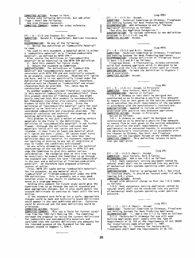
211 - 15 - (3-2.1.7): Reject ~ : Dave Richison, August West Chimney Sweep RECOMMENDATION: I f a masonry f ireplace is to be used as a stove vent, (hearth unit or insert) then al l units require a stainless steel sleeve be connected to the unit d i rect ly and proceed up through the damper area and continue throughout the venting system and terminating at the top of the chimney. The sleeve should be no thinner than .005 m and should be insulated to provide maximum heat transfer throughout the sleeve to increase stack temperature and thus reduce creosote formations.
21
SUBSTANTIATION: Fi reol ace Insert. A masonry f ireplace was never designed as a stove
vent, as a stove vent, a masonry f ireplace has many times the a i r flow that a hearth unit or insert would require. This increase a i r flow reduces heat transfer and results in tremendous production of creosote. Field experience in sweeping as well as stove sales and educational information have resulted in forming my comment. I work with many insurance companies and f i re departments and building code people and feel this problem is a result of improper use of masonry fireplace venting systems.
Wood Stove Inserts. The insert market is one of the most dangerous solid
fuel heating units produced. No one ever conceived that such a unit be placed inside the masonry fireplace. When a stove is inserted into a mas°nry f ireplace, the existing unit is far too large in relation to the 6 in. or 8 in. vent that would normally be required for the vent size of an insert. The thermal mass involved can not ever achiev e the proper temperature to eliminate creosote production (+192 °) because the insert is surging heat into the room and not into the chimney. I t is time to standardize the venting systems on inserts so that a safer insta l la t ion can be accomplished. I could write ten pages on the inserts alone, this would be a start at stopping the tremendous increases in f i re deaths and property loss due to wood stove inserts as well as al l so l id fuel chimney connected heating units.
/
lj i I i
~01 ~ 6 c~-~n ~.q ~P,~-~F ~'~.~ ~.,J
.Revised NFPA 211. The current proposed change woul d recommend the
insta l la t ion of a stainless system through the damper area into the smoke chamber and then stop at that point making this a safe insta l la t ion. This approach is only a half hearted attempt to keep costs down on instal lat ion but does not address the safety issue on the insert market. (See drawing - positive connect.)
Only the direct connect method of insta l l ing an insert properly addresses the safety issue on woodstove insert problems.
The unit is sealed with a i r t igh t stainless pipe allowing the area around the pipe to be preheated by warm house a i r and the .005 thickness of the stainless allows quick heat transfer through the pipe allowing higher stack temperatures.
Other insulating materials can be included to provide even better insulating qual i t ies.
BBckqround. I have been in the wood heating industry for 13
years; 7 years as a chimney sweep, 5 years in the masonry and stainless relining busi,ness and 2 years in the sel l ing of wood stove units. I am also the Vice President of the Ohio Chimney Sweeps Guild, and am currently on the Board of Directors of the Wood Heating Alliance at executive level. I also perform 40-60
speaking engagements per year and am very concerned about the safety of my industry as well as the safety of the consumer. In my stove shop, as an example, I refuse to sell an insert without a direct connect safety system for the consumer as well as the protection of myself in relation to product l i a b i l i t y . (See drawing - direct connect.)
I t is my professional opinion that direct connect policies, not positive connections should be made mandatory for the sake of the consumer or the insert be banned from the industry. COMMITTEE ACTION: Reject. CQ~MITTEE COMMENT:~ This was a "hold for further study" item from the 1983 Fall Meeting TCR. This proposal and others that were held for further study pertain to use of a continuous direct connect as a means of connecting a solid fuel burning appliance to the chimney of a masonry f ireplace and l imi t ing the cross-sectional area of the connector to no more than 1.25 times the area of the appliance flue col lar . The NFPA 211 Standard was revised in 1984 to require that solid fuel burning appliances which use the chimney of a masonry f ireplace be provided with a positive connector which extends from the appliance to the flue l iner . In addition, the cross sectional area of the flue is limited to no more than three times the cross-sectional area of the flue col lar of the appliance. The Committee established the requirements for a direct connect system as a result of input received from National Chimney Sweep Guild. I t was indicated that a direct connect system which terminated at the masonry flue l iner would help to reduce the amount of creosote formation in the smoke chamber of a masonry fireplace which, in turn, would reduce the f i r e severity of a creosote f i r e in the smoke chamber'area. After some discussion,, the Committee concluded that suf f ic ient data had not been developed on the effectiveness of the 1984 direct connect requirement to j us t i f y changing the requirement at this point in time to require a continuous direct connect system. The current requirement does not prohibit using a continuous direct connect system which terminates at the top of the chimney. A Task Group was formed to further review this matter and review f ie ld reports pertaining to the effectiveness of the 1984 direct connect insta l la t ion requirement. I t was intended that the Task Group provide inRut to the Committee during the next review cycle for the NFPA 211 Standard.
(Log #3} 211 - 16 - (3-2.3): Accept in Principle ~LBMITTER: Robert A. Rucker, CMS Industries, Inc. RECOMMENDATION: The suggestion is to replace 3-2.3 with:
3-2.3 Fireclay flue l iners should be instal led ahead of the construction of the chimney a s ' i t is carried up, careful ly bedded one on the other in a medium duty, nonwater soluble refractory cement with close f i t t i n g jo ints l e f t smooth on the inside. SUBSTANTIATION: In reference to 3-2.3 on page 211-16, an option for refractory mortar refers to ASTM-CI05 medium duty. This, in fact, is not correct. ASTM-CI05 refers to f i rec lay. Fireclay is not a refractory cement as i t has no binder. Therefore, i f f i reclay were to be mixed with water alone i t would not ever set up or develop any strength. I f f i rec lay were mixed with Portland ,cement, i t would not meet.minimum temperature requirements to qualify as a refractory cement.
I f the user is fortunate enough to know that f i rec lay should not be used as a refractory mortar, he must answer the following questions before he can assure himself of a quality insta l la t ion. . .
I . What kind of f i reclay is best? 2. What should be added to it? 3. What proportions? 4. What kind of sand is best? 5. How much water should be added? 6. Will i t shrink and crack? 7. Will i t have good workability? 8. How much time before i t sets up? 9. How long w i l l . ' i t last?
lO. Will the f i rec lay manufacturers guarantee the work?
22
We have seen instances where some or al l of these questions have not been answered and as a result,. consumers have been l e f t potential ly hazardous instal lat ions.
The following suggestion may go a long way to eliminate this confusion as there are products engineered and.manufactured complete speci f ical ly for this service, namely, nonwater soluble refractory cement complete with manufacturers instructions, etc. COMMITTEE ACTION: Accept in Principle.
In existing 3-2.3, change "ASTM C. I05 i' to "ASTM . C 199". COMMITTEE COMMENT: ASTM C tO5 has been withdrawn. .The reference .change toC 199 meets the intent of the Submitter. I
(Log #18) 211 - 17 - (3-2.5): Accept in Principle SUBMITTER: Royal Edwards and James Brewer, National Chimney Sweep Guild RECOMMENDATION: Revise 3-2.5 as follows:
3-2.5 Flue l in ing for residential and low heat chimneys shall be separated from the chimney wall by a I minimum of I /2 in. and a maximum of 8 in. of a i r ... I space. The a i r space shall not be f i l l ed and only enough mortar shall be used to make a good jo in t and hold the l iners in position. SUBSTANTIATION: At present there is no maximum l im i t , the a i r space can be as large as the mason wants i t to be. Often i t is 4 to 6 f t or more.
Large a i r spaces between l iner and chimney wall make weak and dangerous chimneys. I f the l iner sections do not hav e lateral support they can collapse very easily in the event of a chimney f i re , lightning str ike, or earth tremor. In the event of a chimney f i re , i f one of the lower flue l iners crack or sh i f t , al l the l iners above (with the possible exception of the top l iner which may be held by the crown) can come tumbling down. COMMITTEE ACTION: Accept in Principle.
Change "8 in." to " l in." so that revised subsection 3-2.5 reads as follows:
3-2.5. Flue l ining for residenlial and low heat chimneys shall .be separated from .the. chimney wall by a -, minimum of I /2 in. (12.7 mm) and a maximum of l in. (25 mm) of a i r space. The a i r space shall not be f i l l ed and only enough mortar shall be used to make a good jo in t and hold the l iners in position.
Exception: When masonry chimneys are lined with a l isted chimney.liner system, the system shall be installed in accordance with the l i s t ing . COMMITTEE COMMENT: The change from "8 in." to "l in." is to improve.construction so that there wi l l be less likelihood of the l ining shif t ing and less chance of l iner movement or collapse.
"'i (Log #33)
211 - 18 ~ ( 4 - I . I ) : Accept . SUBM'ITTER: Technical Committee onChimneys, Fireplaces and Venting Systems for Heat:Producing Appliances RECOMMENDATION:. Change subsection to read as follows:
4-I.1 Single-wall metal chimneys or unlisted metal chimneys shall not be used inside or outside of one- and two-family dwellings. SUBSTANTIATION: To c la r i f y the intent of the Committee. ~O~MITTEE ACTION: Accept. ..
(Log #19) ' 211 - 19 - iA-2.2.1. I ) : Accept SUBMITTER: Royal Edwards and Dave Johnston National Chimney Sweep Guild RECOMMENDATION: Change,"6 in." to "18 in."
. , . . .
SUBSTANTIATION: For f i re safety a stove pipe requires a6 18 in., clearance to combustibles. This is a similar device in that i t is a single wall metal device. We feel the required clearance should be 18 in. Is there proof that 6. in. is safe? ., .. ~OMMITTEE ACTION: Accept.. ":.. . . . .
, • . ~ 3
. . . . . . '('" o g ~ # 3 4 ) ~'~" '=' 211 - 20 - (Figure 5-5): "Accept , '" ~ : Technical Committee' on Chimn'~ys, Fir'e~laces and Venting Systems for Heat Producing Appliances RECOMMENDATION: Remove spacer from behind the vent or connector in Figure 5-5. SUBSTANTIATION: Proposal is to correct Figure 5-5 as noted in Figures 8-7(a) and 8-7(d) "Do not use spacers direct ly behind appliance or connector.'.' qOMMITTEE ACTION: Accept. . -
L ~ r .
2 1 1 - 21 - ( T a b l e 5 - 5 ( b ) ) : A - c c e p ~ " ( ' L d g . ..... #25)
SUBMITTER: Richard D. Peacock, Nati9na!' Bureau o'f .. Standards RECOMMENDATION: Revise Table 5-5(b) to'rea~ :as fol'lows (Table 5-5(b) shown on the following page):, ' SUBSTANTIATION: Table'8-7(b) was'revised'in ~:he l~st revision of NFPA 211 based "iJpbn the results' of're'search at the National Bureau of S'tanda'rds*. The "new Table 5-5(b) is s~mply the corollary to Table 8-7(b) for use with chimney connectors. The research showed that' the clearance reductions are equally applic'ablt~'to chlmney''~' connectors as they are to. appliance clearance reduction. The proposed table provides be ttei': .- . described and more f lex ib le protection systems..bas'ed' upon solid research evidence of thei r sui tabi l i ' ty . Both changes make the clearance reduction systems consistent throughout .the st.~6dard.
~Loftus, 3.J., and Peacock," R.D., C'learances'and" " Methods of Protection for Wall and Ceiling Surfaces • Exposed to Radiant Heating Appliances, Nat.. Bur.. Stand. (U.S.), NBSTN 1205 (December 1984). , . ,.. COMMITTEE ACTION: Accept.
" = " ' ' ' " (Lo'g # 2 6 ) ' r 211 - 22 - (5-5.5 and 5L5.6 INew) : Accepti=: "' ~UBMITTER: Richard D. Peacock National Bureau of "' Standards " : ' " "
r , r
RECOMMENDATION: Add new sections 515.5 ahd 5-5.6 to read as follows:
5-5.5 For clearance reduction Systems using an a i r space between the combustible wall and ~t~e ~al'1' protector, adequate a i r ci.rculatiomshall be. pffovided by one of the following ~ethods. • ":: " '. " '
5-5.5.1 Adequate a i r circulat ion may be. provided by leaving al l edges of the wall protector open with at least.a l - in . (25.4-mm) a i r gap . . . . . ..- .
5-5.5.2 I f the wall protector"is mounteB'oh a s'ingle f l a t wall away from corners, adequate a i r ci'/cul:ation ; may be provided by leaving only. the bottom and top edges or only the side and top~ edges.oRen with at least' a . l - i n . (25.4-mm) a i r gap.
5-5.5.3 Wall protectors that cover'two w~l~Is" in a corner shall be oRen at the bottom and top. edges with at least a l - i h . (25.4-mm) a.ir gap. • , .
5-5.6' All clearances shall 'be measured from the outer surface of the combustible material to the nearest point on the surface o.f the cohnector, ~''~ ' disregarding any "intervening prote'cEion applied to the combustible material. SUBSTANTIATION: The .new sections 5=5.S~"a6d~5-5.6 'are adapted'from Chapt'er 8 to 'go along ~'i~h"the proposed new Table .5-5(b). ,The sections, provide ,guidance ,for required air ' reduction systems con's'isEent .t~Tgughout the standard. COMMITTEE ACTION: Accept. - , .
23
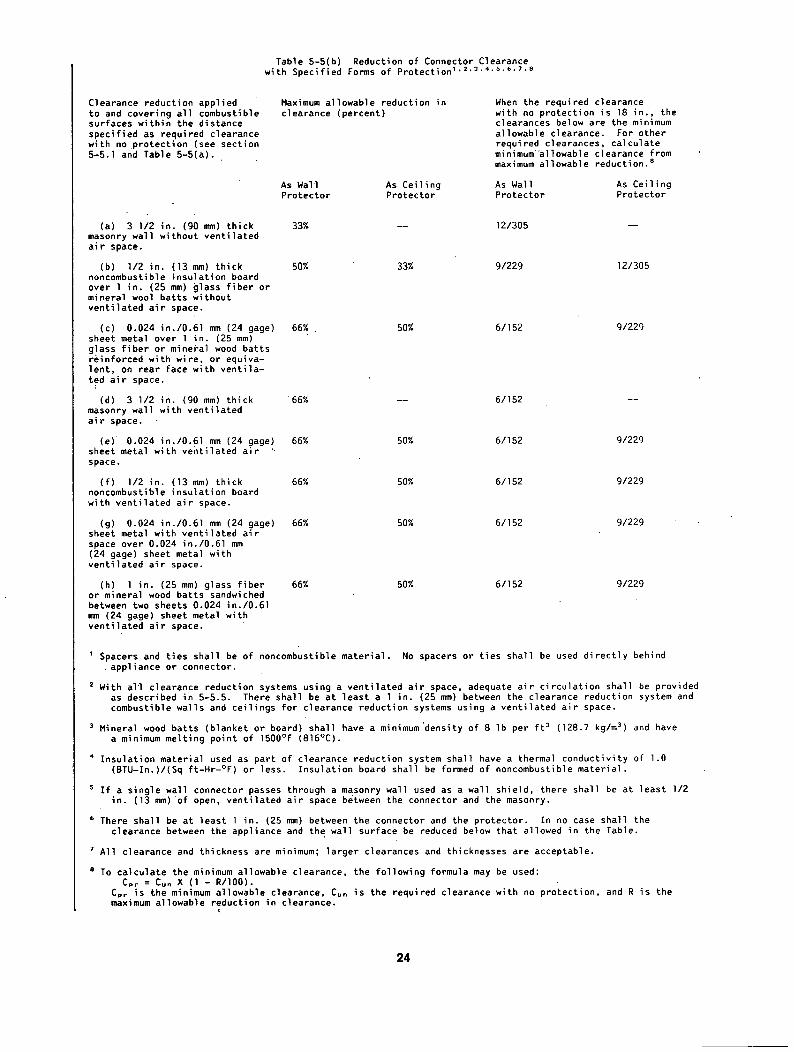
Table 5-5(b) Reduction of Connector Clearance with Specified Forms of Protection 1"2"3"4.s'6"7"B
Clearance reduction applied to and covering al l combustible surfaces within the distance specified as required clearance with no protection (see section 5-5.1 and Table 5-5(a).
Maximum allowable reduction in clearance (percent)
When the required clearance with no protection is 18 i n . , the clearances below are the minimum allowable clearance. For other required clearances, calculate minimum"allowable clearance from maximum allowable reductlon, s
As Wall As Ceiling As Wall As Ceiling Protector Protector Protector Protector
(a) 3 I /2 in. (90 mm) thick 33% masonry wall without ventilated a i r space.
(b) I /2 in. (13 mm) thick 50% noncombustible insulation board over I in. (25 mm) glass f iber or mineral wool batts without ventilated a i r space.
(c) 0.024 in./O.61 mm (24 gage) 66% sheet metal over I in. (25 mm) glass f iber or mineral wood batts reinforced with wire, or equiva- lent, on rear face with vent i la- ted a i r space.
(d) 3 I /2 in. (90 mm) thick 66% masonry wall with ventilated a i r space.
(e) 0.024 in./O.61 mm (24 gage) 66% sheet metal with ventilated a i r space.
( f ) I /2 in. (13 mm) thick 66% noncombustible insulation board with ventilated a i r space.
(g) 0.024 in./O.6l mm (24 gage) 66% sheet metal with ventilated a i r space over 0.024 in./O.61 mm (24 gage) sheet metal with ventilated a i r space.
(h) I in. (25 mm) glass f iber 66% or mineral wood batts sandwiched between two sheets 0.024 in./O.61 mm (24 gage) sheet metal with ventilated a i r space.
12/305
33% 9/229 12/305
50% 6/152 9/229
6/152
50% 6/152 9/229
50% 6/152 9/229
50% 6/152 9/229
50% 6/152 9/229
1 Spacers and t ies shall be of noncombustible material. No spacers or t ies shall be used di rect ly behind appliance or connector.
2 With al l clearance reduction systems using a ventilated a i r space, adequate a i r circulat ion shall be provided as described in 5-5.5. There shall be at least a l in. (25 mm) between the clearance reduction system and combustible walls and ceilings for clearance reduction systems using a ventilated a i r space.
3 Mineral wood batts (blanket or board) shall have a minimum'density of 8 Ib per f t 3 (128.7 kg/m 3) and have a minimum melting point of 1500°F (816°C).
4 Insulation material used as part of clearance reduction system shall have a thermal conductivity of l.O (BTU-In.)/(Sq ft-Hr-°F) or less. Insulation board shall be formed of noncombustible material.
s I f a single wall connector passes through a masonry wall used as a wall shield, there shall be at least I /2 in. (13 mm) of open, ventilated a i r space between the connector and the masonry.
6 There shall be at least I in. (25 mm) between the connector and the protector. In no case shall the clearance between the appliance and the wall surface be reduced below that allowed in the Table.
All clearance and thickness are minimum; larger clearances and thicknesses are acceptable.
8 To calculate the minimum allowable clearance, the following formula may be used: Cpr = Curt X ( 1 - R/IO0).
Cpr is the minimum allowable clearance, Cun is the required clearance with no protection, and R is the maximum allowable reduction in clearance.
24
(Log #20) 211 - 23 - (5-7.1): Accept in Principle ~UBMITTER: Royal Edwards and Dave Johnston, National Chimney Sweep Guild RECOMMENDATION: Add a new 5-7.1.1 to read as follows:
5-7.1.I For residential type appliances the cross-sectional area of the fluE, shall not be less than the cross-sectional area'of the appliance flue col lar. The cross-sectional area of the flue shall not be more than three times the cross-sectional area of the appliance flue col lar .
"SUBSTANTIATION: This is a requirement with masonry f i re place flues and should be extended to al l residential appliances to avoid draf t problems. COMMITTEE ACTION: Accept in Principle.
Renumber as 8-5.4 and add "solid fuel burning" following residential type so that new subsection reads as follows:
8-5.4 For residential type solid fuel burning appliances the cross-sectional area of the flue shall not be less than the cross-sectional area of the appliance flue col lar. The cross-sectional area of the flue shall not be more than three times the cross-sectional area of the appliance flue collar..
Renumber existing 8-5.4 and 8-5.5. COMMITTEE COMMENT: The Committee feels that the subsection is applicable to Chapter 8, Solid Fuel Burning Appliances.
(Log #2) 211 - 24 - (5-7.4): Reject ~ : Henry B Swan, Vermont Mutual Insurance Co. RECOMMENDATION: Revise 5-7.4 as follows:
5-7.4 That an assembly consisting of noncombustible insulating materials, metal clad on the exter ior connector a distance of 12 in. from point of entr~ be included as a recommended method of combustible wall
penetration. Any unit must be tested in accordance with UL 103 standard for safety~"chimneys - factory bu i l t , i nc lud ing category, "chimney and vent connectors and accessories" - Guide DDey and be l isted for 2100 Degree F - (HT). SUBSTANTIATION: Presently, there is only one recommended means of combustible wall penetration with, a chimney connector. The one means is by using, a section of prefabricated metal chimney in a horizontal "position. For the most part, this type of pipe is not UL l isted above 1500 Degree F, great d i f f i cu l ty .a r ises in the instal lat ion, when installed horizontal ly, the interest of approval agencies is in doubt. COMMITTEE ACTION: Reject. COMMITTEE COMMENT: The intent of the Recommendation is covered by Proposal 211-26 (Log #27).
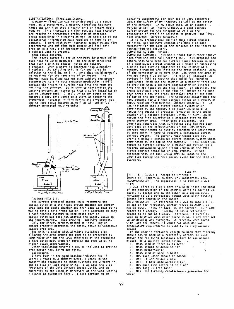
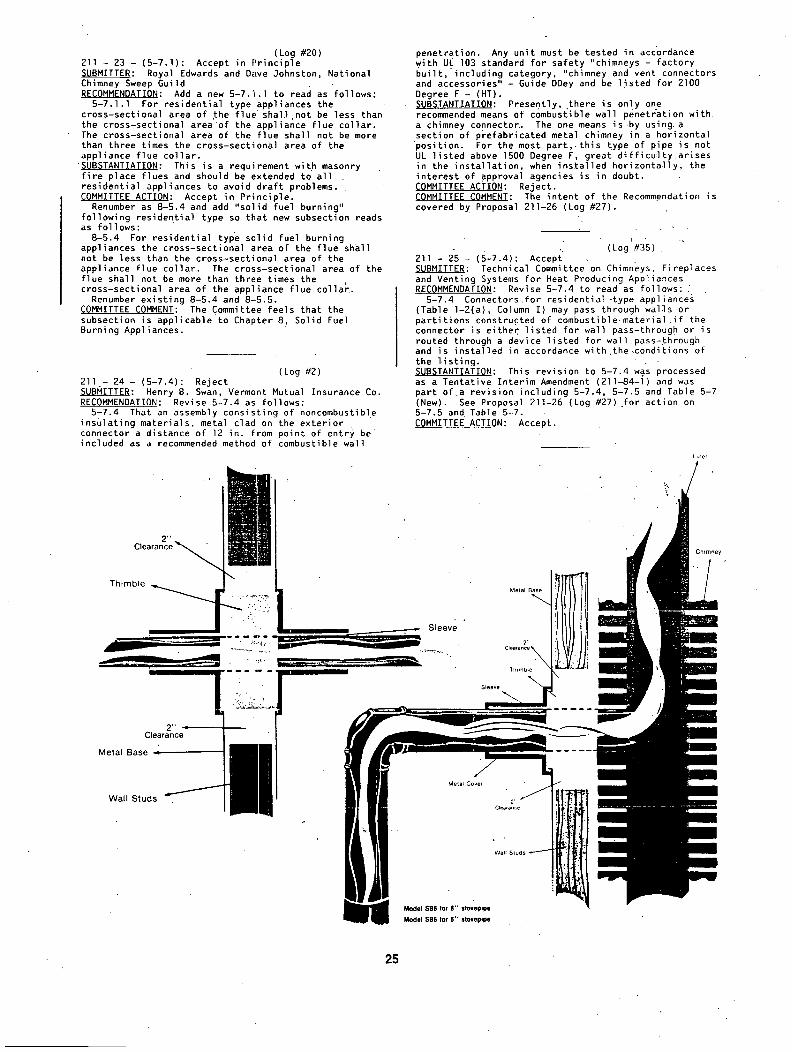
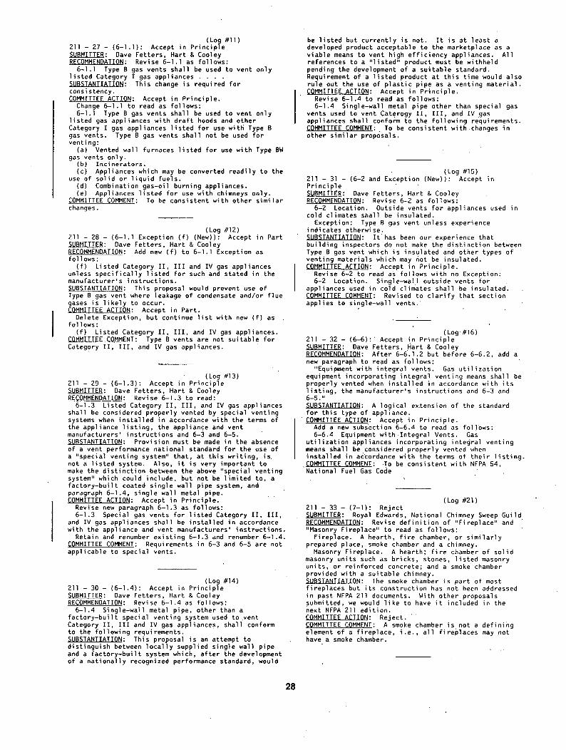
( L o g ~ # 3 5 ) . 211 - 25 - (5-7.4): Accep£" .. SUBMITTER: Technical Committee on Chimneys, Fireplaces and Venting Systems for Heat Producing Appliances RECOMMENDATION: Revise 5-?.4 to read as fo l lows: ,
5-7.4 Connectors.for residential-type appliances (Table I-2(a), Column I) may pass through wal3s.or part i t ions constructed of combustible material i f the connector is either l isted for wall pass-through or is routed through a device l isted for wall pass-~hrough and is installed in accordance with.the.conditions of the l i s t ing . SUBSTANTIATION: This revision to 5-?.4 w@s processed as a Tentative Interim Amendment (211-84-I) and was part of a revision including 5-7.4, 5-7.5 and Table 5-7 (New). See Proposal 211-26 Log #27) ~or action on 5-7.5 and Table 5-7. COMMITTEE ACTION: Accept.
Lmer
2 " C lea rance ~ , , , ~ .
_ _ ~ . S l e e v e r ' ~
2 " - C lea rance
M e t a l B a s e 4
Metal Base
2" Cleatance~, Thimble
Chimney
W a l l S t u d s 2' Oeo,~nce
Model $B8 for 8" stovepipe
Modet SB6 for S" $tovopipe
25
(Log #27) 2 l l - 26 - (5-7.5 and Table 5-7 (New)!: Accept in Pr inc ip le ~ : Richard D. Peacock, National Bureau of Standards RECOMMENDATION: Revise 5-7.5 as proposed in TIA #188 to read as fo l l ows :
5-7.5 Connectors f o r r es i den t i a l - t ype appliances (Table l - 2 (a ) , Column I ) wi th inside diameters less than or equal to 10 in . (254 mm) may pass through wal ls or pa r t i t i ons constructed of combustible mater ia l to a masonry chimney i f the connector system selected or fabr icated is i n s t a l l e d in accordance with the condit ions and clearances in Table 5-7.
Rev ise f i r s t sentence fo r system B in Table 5-7 as proposed in TIA #188 to read as fo l lows : '
B. Solid insulated l i s t e d f a c t o r y - b u i l t chimney length of the same ins ide diameter as the chimney connector and having 1 in. (25 mm) or more of insu la t ion wi th a minimum g in. (229 mm) a i r space between the outer wall of chimney sect ion and combustibles.
Revise f i r s t sentence for system C in Table 5-7 as proposed in TIA #188 to read as follows:
C. Sheet steel chimney connector, minimum 24 gage (0.024 in./O.61 mm) in thickness, with a ventilated thimble, minimum 24 gage (0.024 in./0.61 mm) in thickness, having two l in. (25 mm) a i r channels, separated from combustibles by a minimum of 6 in. (152 mm) of glass f iber insulation.
Add the following sentence to the end of the description for system C in Table 5-7 as proposed in TIA #188.
"Any unexposed combustible material adjacent to a wall pass-through system.shall be covered with unpainted sheet steel, minimum 24 gage (O.024-in./O.61-mm) in thickness."
Revise f i r s t sentence for system D in Table 5-7 as proposed in TIA #188 to read as follows:
D. Solid insulated l isted factory-bui l t chimney length with an inside diameter 2 in. (51. mm) larger than the chimney connector and having I in. (25 mm) or more of insulation, serving as a pass-through for a single wall sheet steel chimney connector, minimum 24 gage (0.024 in./O.61 mm) in thickness, with a minimum 2 in. (51 rnm) a i r space between the outer wall of chimney section and combustibles.
Revise last sentence for systems B, C, and D in Table 5-7 as proposed in TIA #188 to read as follows:
"Supports shall be securely fastened to wall surfaces in al l sides but shall be sized to f i t and hold chimney section. Fasteners used to secure chimney sections shall not penetrate chimney section. SUBSTANTIATION: I . The original TIA proposed a limited number of wall pass through systems for only 6 in. inside diameter chimney connectors. Larger sizes, within reason, are common. The proposed changes make allowances for up to 10 in. diameter chimney connectors without changing other requirements of the provisions. Since the systems proposed in the TIA were tested to I100 to 1200°F, higher than the IO00°F operating temperature in NFPA 211, no added risk is introduced by the change.
2. The sentence added to the end of the description for system C rect i f ies an oversight in the original proposal. The research the TIA was based upon used a sheet steel covering on the wall studding adjacent to this wall pass-through system as i t penetrated the wall.
3. The revised sentence at the end of the descriptions for systems B, C, and "D provides for the chimney sections to be secured with fasteners (such as wall bands supplied by the chimney manufacturer), but insures that nothing penetrates the chimney wa l l s . COMMITTEE ACTION: Accept in Principle.
Delete the second sentence that was proposed to be added to the description for System C in Table 5-7. Change last word oF revised sentence for Systems B, C, and D to "f lue l iner" . Revise Figure B for c la r i t y ; add new Note 5; and delete Note 4, adding last sentence to 5-7.5. Revised 5-7.5 and Table 5-7 wi l l read as follows:
5-7.5 Connectors for residential-type appliances (Table l-2(a), Column I) with inside di.ameters less than or equal to'10 in. (254 mm) may pass through walls or part i t ions constructed of combustible material to a masonry chimney i f the connector system selected or fabricated is installed in accordance with the conditions and clearances in Table 5-7. Any unexposed metal that is used as part of a wall pass-through system and is exposed to flue gases shall be constructed of stainless steel or other equivalent material that wi l l resist corrosion, softening, or cracking from fluegases at temperatures up to 1800°F (982°C). COMMITTEE COMMENT: Revisions made to c la r i f y the intent of the Submitter and of the Committee.
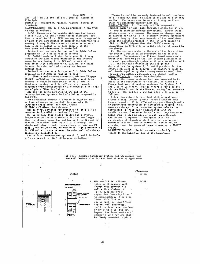
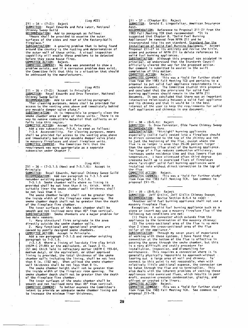
Table 5-7 Chimney Connector Systems and Clearances from Rom Wall Combustibles for Residential Heating Appliances
. . . . . j , ,
II
System
w~v~v c ~ w
M I , ~ , m c y
~.-~'~,
A. Minimum 3.5 in. (90-mm) thick brick masonry wall framed into combustible wall with a minimum of 12 in. (305'mm) brick separation from clay l i n e r ' to combustibles. Fire clay l iner (ASTM C315 or equivalent), minimum 5/8-in (16-mm) wall thickness, shall run from outer surface of brick wall to, but not beyond, the inner surface of chimney flue l iner and shall be f irmly cemented in place.
Clearance in mm
12/305
26
, - , .
System
/
, , t
T a b l e 5 - 7 c o n ' t
B~ Solild insulated l i s ted f a c t o r y - b u i l t chimney length of the same inside diameter as the chimney connector and
',having I in. (25 mm)'or more." of insulat ion with a minimum
"9 in. (229 mm) ai6 space between the outer wall of chimney section and combustibles. Supports shall be securely fastened to wall surfaces on a l l , . sides and shall be sized to f i t
• and hold chimney section. ' Fasteners used to sec, ure chimney
' " sections shall not penetrate chimney • ~' •flue l i ne r . '
• "/0.6] mm) in thickness, with a ' Venti lated tEimble, minimum ~24
gage (0•024 in./O.61 mm) in ~thickness, havin'g two l in. • (25 mm) a i r channels, separated -'from combustibles by a minimu~
of 6 in. (152 mm) of 'g lass f i be r ~' ,~= r ' ' r '" '" ' insulat ion.
" J ~ : ~ r ~ 1 , - ~. Opening shall be cov'ere'd and "thimble : J I m (=s ~ -
l ~c~..,,...~. minimum 24 gage (0.024 in•/0.61 mm) in thickness. ' , " Supports sh'all be securely fastened
~,~.--. ~ 2 . . ~ .. to wall surfaces on a l l sides and. . . . . c , s , . . ~ shall be sized "to f i t ' a n d hold c~,,.:,~ ~ ~a~,..~u,.., : chimney section• Fasteners used "
.~."~',~,' ' " " " ' ": " -'.to secure chimney secti'ons shall t, -~ • -' ~,' not penetrate chimney f lue l iner •
- . '" " D. Solid insu•lated l i s ted 2/51 ' " " " f a c t o r y - b u i l t chimney length
"' " ' ' " " " ~ ' with an inside diameter 2 in. " ". " ~ •~: (51 mm) larger than the'chimney . "
• connector and having I in. (25 mm) " "" : ' ;' ,-:-~ &r more ~f insulat ion, serving'as ' :
. . . . . . . . ,•a. pass-through' fo r a single •wall ~ ~ i •,•sheet steel chimney connector, "
] ~ ~'in the thickness wi'th;a minimum " ' "2 In• (51 mm) a l r space between the
I " ~ ' . . :~c . . . , , . . . . , . . '~ Outer wall of chimney section and " " ~ _ ~ . N , , , ~ " ' " . . c o m b u s t i b l e s • • . "' , . . •
' ~I~'%Z_RI"4~ . . . . ~ " Minimum length of chimney section • b~. . . . .~ ' . " " " ' ' sha l l be 12 in..(305"mm). Chimney
~.."~,. " section concentri'~ with and spaced .~. , , , , l in. (25 mm) away from"connectqr by
means of sheet steel support plates on both ends of chimney section•
" " O p e n i n g . s h a l l be c o v e r e d ' a n d , " ~ " . . - c h i m n e y s e c t i o n s u p p o r t e d On b o t h
' '" in thickness•. " ' . . " S u p p o r t s 'shal'l be securely fastened
• to wall surfaces on a l l sides and ' "sha l l be sized to f i t ' and hold
chimney section• Fasteners used .... ' "' " .... to secure c~imney sec.tions shall
"~ not penetrate chimney f lue l i ne r • , j i , , , '
Addit'ional "RequiPements: , . . , , . , c I . Insulat ion material used a s ' p a r t ' o f a wall pas.s-through system shall be of
noncombustible, material and shall have a thermal conduct iv i ty of l.O BTU-in. / f t2.°F (4•88 kg.cal/hr-m2-'°C) or, less;~
2. Al l clearances and thicknesses are:minimums; ~arger'clearances and thicknes'ses are acceptable. " " ; ' " "
3. Any material used to close up an'openiSg fo'r the connector shall be:of ' noncombustible material• ' '
4. A connector to a masonry chimney shall extend in one piece'throu.gh'the wall pass-through system and the chimney wall to the inner face of the f lud l i ne r , but not b e y o n d . .,
•27
(Log #11) 211 - 27 - (6-1.1): Accept in Principle ~ : Dave Fetters, Hart & Cooley RECOMMENDATION: Revise 6-1.1 as follows:
6-1.1 Type B gas vents shall be used to vent only l isted Category I gas appliances . . . . SUBSTANTIATION: This change is required for consistency. COMMITTEE ACTION: Accept in Principle.
Change 6 - I . I to read as follows: 6-1.1 Type B gas vents shall be used to vent only
l isted gas appliances with draf t hoods and other Category I gas appliances l isted for use with Type B gas vents. Type B gas vents shall not be used for venting:
(a) Vented wall furnaces l isted for use with Type BW gas vents only.
(b) Incinerators. (C) Appliances which may be converted readily to the
use of solid or l iquid fuels. (d) Combination gas-oil burning appliances. (e) Appliances l isted for use with chimneys only.
COMMITTEE COMMENT: To be consistent with other similar changes.
(Log #12) 211 - 28 - ( 6 - I . I Exception ( f ) (New)): Accept in Part ~ : Dave Fetters, Hart & Cooley RECOMMENDATION: Add new (f) to 6 - I . I Exception as follows:
( f ) Listed Category I I , I I I and IV gas appliances unless speci f ical ly l isted for such and stated in the manufacturer's instructions. SUBSTANTIATION: This proposal would prevent use of Type B gas vent where leakage of condensate and/or flue gases is l i ke ly to occur. COMMITTEE ACTION: Accept in Part.
Delete Exception, but continue l i s t with new (f) as follows:
( f ) Listed Category I I , I I I , and IV gas appliances. COMMITTEE COMMENT: Type B vents are not suitable for CategorY I I , I I I , and IV gas appliances.
(Log #13) 211 - 29 - (6- I .3) : Accept in Principle ~ : Dave Fetters, Hart & Cooley RECOMMENDATION: Revise 6-I .3 to read:
6-I .3 Listed Category I I , I I I , and IV gas appliances shall be considered properly vented by special venting systems when instal led in accordance with the terms of the appliance l i s t i ng , the appliance and vent manufacturers' instructions and 6-3 and 6-5. SUBSTANTIATION: Provision must be made in the absence of a vent performance national standard for the use of a "special venting system" that, at this wri t ing, i s not a l isted system. Also, i t is very important to make the dist inct ion between the above "special venting system" which could include, but not be limited to, a factory-bui l t coated single wall pipe system, and paragraph 6-1.4, single wall metal pipe. COMMITTEE ACTION: Accept in Principle.
Revise new paragraph 6-I .3 as follows: 6-1.3 Special gas vents for l isted Category I f , I I I ,
and IV gas appliances shall be installed in accordance with the appliance and vent manufacturers' instructions.
Retain and renumber existing 6-1.3 and renumber 6-1.4. COMMITTEE COMMENT: Requirements in 6-3 and 6-5 are not applicable to special vents.
(Log #14) 211 - 30 - (6- I .4) : Accept in Principle SUBMITTER: Dave Fetters, Hart & Cooley RECOMMENDATION: Revise 6- I .4 as follows:
6-1.4 Single-wall metal pipe, other than a factory-bui l t special venting system used tovent Category I I , I I I and IV gas appliances, shall conform to the following requirements. SUBSTANTIATION: This proposal is an attempt to distinguish between local ly supplied single wall pipe and a factory-bui l t system which, af ter the development of a nationally recognized performance standard, would
be l isted but currently is not. I t is at least a developed product acceptable to the marketplace as a viable means to vent high eff iciency appliances. All references to a " l is ted" product must be withheld pending the development of a suitable standard. Requirement of a l is ted product at this time would also rule out the use of plast ic pipe as a venting material. COMMITTEE ACTION: Accept in Principle.
Revise 6-1.4 to read as follows: 6-I .4 Single-wall metal pipe other than special gas
vents used to vent Caterogy I I , I I I , and IV gas appliances shall conform to the following requirements. ~OMMITTEE ~OMMENT:. To be consistent with,changes in other similar proposals.
Log #15) 211 - 31 - (6-2 and Exception (New) : Accept in Principle ~MITTER: Dave Fetters, Hart & Cooley RECOMMENDATION: Revise 6-2 as follows:
6-2 Location. Outside vents for appliances used in cold climates shall be insulated.
Exception: Type B gas vent unless experience indicates otherwise. SUBSTANTIATION: I t h a s been our experience that building inspectors do not make the dist inct ion between Type B gas vent which is insulated and other types of venting materials which may not be insulated. COMMITTEE ACTION: Accept in Principle.
Revise 6-2 to read as follows with no Exception: 6-2 Location. Single-wall outside vents for
appliances used in cold climates shall be insulated. COMMITTEE COMMENT: Revised to c la r i f y that section applies to single-wall vents.
(Log.#16) 211 - 32 - (6-6):" Accept in Principle ~ : Dave Fetters, Hart & Cooley RECOMMENDATION: After 6-6'.I.2 but before 6-6.2, add a new paragraph to read as follows:
"Equipment with integral vents. Gas u t i l i za t ion equipment incorporating integral venting means shall be properly vented when instal led in accordance with i ts l i s t ing , the manufacturer's instructions and 6-3 and 6-5." SUBSTANTIATION: A logical extension of the standard for this type of appliance. COMMITTEE ACTION: Accept in Principle.
Add a new subsection 6-6.4 to read as follows: 6-6.4 Equipment with Integral Vents. Gas
u t i l i za t ion appliances incorporating integral venting means shall be considered properly vented when installed in accordance with the terms of thei r l i s t i ng .
,COMMITTEE COMMENT: To be consistent with NFPA 54, National Fuel Gas Code
(Log #21) 2l l - 33 - (7- I ) : Reject SUBMITTER: Royal Edwards, National Chimney Sweep Guild RECOMMENDATION: Revise def in i t ion of "Fireplace" and "Masonry Fireplace" to read as follows:
Fireplace. A hearth, f i re chamber, or similar ly prepared place, smoke chamber and a chimney.
Masonry Fireplace. A hearth; f i re chamber of solid masonry units such as bricks, stones, l isted masonry units, or reinforced concrete; and a smoke chamber provided with a suitable chimney. SUBSTANTIATION: The smoke chamber is part of most fireplaces but i ts construction has not been addressed in past NFPA 21l documents. With other proposals submitted, we would l ike to have i t included in the next NFPA 211 edition. COMMITTEE ACTION: R e j e c t . COMMITTEE COMMENT: A smoke chamber is not a defining element of a f ireplace, i . e . , al l fireplaces may not have a smoke chamber.
28
-" " (Log #22) 211 - 34 - (7-2): Reject SUBMITTER: Royal Edwards and Pete Luter, National Chimney Sweep Guild RECOMMENDATION: Add to paragraph as follows:
"Means shall be provided to examine the outer surfaces of the" sides and rear of the factory-b'uilt f i replace." SUBSTANTIATION: A growing problem that is being found around the country is the rusting and deterioration of
t h e outer wall of these units. A visual inspection capabil i ty wi l l enable these problems to be detected before they cause house f i res. COMMITTEE ACTION: Reject. COMMITTEE COMMENT: 'No data was presented to show a problem exists, and i f a corrosion problem does exist, the Committee f e l t that this is a situation that should be addressed by the manufacturers.
(Log #23) 211 - 35 - (7-2): Accept in Principle ~ : Royal Edwards and Drew Forester, National Chimney Sweep Guild RECOMMENDATION: Add to end of existing paragraph:
"For cleaning purposes, means shall be provided for access to the venting area above and immediately behind any movable damper valve plate." SUBSTANTIATION: I t i s imposs ib le to properly clean the smoke chamber area of many of these units." There is no way to remove combustible material that collects on or fa l l s into this region." COMMITTEE ACTION: Accept in Principle.
Add a new subsection, 7-3.4, to read as follows: 7-3.4 Accessability. For cleaning purposes, means
shall be provided for access to the venting area above and immediately behind any movable damper'valve plate in masonry fireplaces and steel f ireplace units. COMMITTEE COMMENT: The Committee f e l t that the requirement was more appropriate as a separate subsection under Chapter 7.
(Log #24) 211 - 36 - (7-3.1.5 (New) and 7-3.1.6): Accept in Principle ~ : Royal Edwards, National Chimney Sweep Guild RECOMMENDATION: Add new paragraph to 7-3.1.5 and renumber existing paragraph to 7-3.1.6.
7-3.1.5 Smoke chamber walls where no l ining is provided shall be not less than 8 in. thick. With a suitable l iner the smoke chamber wall thickness shall be not less than 4 in.
The smoke chamber height shall not be greater than the inside width of the fireplace room opening. The smoke chamber depth shall not be greater than the depth of the fireplace f i re chamber.
The inner surfaces of the smoke chamber shal l be smooth and not inclined more than 45 ° from ver t ica l . SUBSTANTIATION: Smoke chambers are a major problem for two main reasons.
I . Many structural f i res originate in the area direct ly outside the smoke chamber walls.
2. Many functional and operational problems are caused by poorly designed'smoke chambers. ~OMMITTEE ACTION: Accept in Principle.
Add a new paragraph 7-3.1.5 and renumber existing Raragraph to 7-3.1.6.
7-3.1.5 Where a l in ing of low--duty f i r e clay brick (ASTM C 27-84) or the equivalent, at least 2 in. (51 mm) thick laid in refractory mortar (ASTM C 199-64, medium duty), or the equivalent, or other approved l in ing is provided, the total thickness of the smoke chamber'walls including the l ining, shall be not less than 6 in. (152 mm). When unlined the smoke chamber wall thickness shall be not less than 8 in.
The smoke chamber height shall not be greater than the inside width of the fireplace room opening. The smoke chamber depth shall not be greater than the depth of the "fireplace ~ire chamber.
The inner surfaces of the smoke chamber shall be smooth and not inclined more than 45 ° from vert ical . COMMITTEE COMMENT: To better express the Committee's intent to provide an adequate smoke chamber l in ing and to increase the minimum l iner thickness.
211 - 37 - (Chapter 8): Reject ~ : Gerald E. Lingenfelter American Insurance Assn. RECOMMENDATION: Reference to Proposal 211-27 from the 1983 Fall .Meeting TCR that recommended: " I t is suggested that Chapter 8, "Solid Fuel Burning Appliances" be removed from NFPA 211 and be incorporated into i ts own standard, Standard for the Instal lat ion of Solid Fuel Bvrnino Eouioment." Accept Proposal 211-27 in i ts entirety and revise t h e ' t i t l e , scope and purpose of NFPA 211 to delete "references to solid fuel burning appliances. SUBSTANTIATION: Although this proposal was accepted in principal, we understand that the Standards Council o f f i c i a l l y cleared the way for the proposed action. Our comment issubmitted to ass is t ' in the swift completion of this matter. COMMITTEE ACTION: Reject. COMMITTEE COMMENT: 'This was a "hold for "further study" item from the 1983 Fall Meeting TCD and pertains to a proposal to put solid fuel appliance requirements in a separate document. The Committee studied thi's proposal and concluded that the provisions for solid fuel burning appliances should remain in theNFPA 211 document. I t was concluded that there was an important interactive relationshi P between a solid Fuel appliance and i ts chimney and that i t would be in the best interest of the user to keep the requirements for solid fuel appliances and chimneys in one document.
J
211 - 38 - (8-5.4): Reject SUBMITTER: G. Drew Forrester, Olde Towne Chimney Sweep RECOMMENDATION: None. SUBSTANTIATION: " "Ai r t ight" burning appliances especially (solid fuel) vented into a f ireplace should be.direct connected to the top of the chimney and not to ~ust the beginning of the flue, except where the flue is no larger in area than 25-30 percent larger than the.opening (flue s ize) 'of the burning appliance. Too large of a flue reduces combustion eff ic iency, increases smoke residence time and thus Towers flue gas temperature. I have witnessed often third degree creosote bui l t up in oversized flues of fireplaces where "a i r t igh t " solid fuel burning appliances were installed into without direct'connection to the top of the f lue. COMMITTEE ACTION: Reject. COMMITTEE COMMENT: This was a "hold for further study" item from the 1983 Fall Meeting TCR. See comment to proposal 211-15.
211 - 39 - ( 8 - 5 . 4 ) : Re jec t ~ : J e f f G i t l i n , J e f f G i t l i n Chimney Sweeps. RECOMMENDATIOn: R e v i s e ' S e c t i o n 8 : 5 . 4 to read: ,
"Ano the r s o l i d f u e l - b u r n i n g app l i ance sha l l not use a masonry fireplace flue.
Exception: A sol ld'fuel burning appliance such as a stove or insert may use a masonry fireplace flue i f the following two conditions'are met:
( I ) There is a connector which extends from the appliance to the termination of the masonry chimney.;
(2) The cross-sectional area of the flue is no more than 2 times the cross-sectional area of the Flue col lar of the appliance." SUBSTANTIATION: Through my seven years of'experience of working with these systems, I have found that a connection at the bottom of the flue is effect ive in passing the gases through the smoke chamber, but this is a very d i f f i c u l t and costly procedure For insta l lat ion, inspection, and dismantling for maintenance. This requires a connection where i t is
general ly physically impossible to approach!without tearing out a large area of wall and chimney. 'To" connect to this point ' is not reasonable, when with re lat ive ly l i t t l e additional expense, the connector can be taken through the flue and to termination. Thi's also deals with the inherent problems of venting these appliances into oversized flues, which results in poor draf t , excessive creosote condensation, glazing, and of f -set or cracked t i l e l iners. ~OMMITTEE ACTION: Reject. • COMMITTEE COMMENT: This was a "hold for further study" item from the Ig83 Fall Meeting'TCR. See comment to proposal,211-15.
29
(Log #4) 211 - 40 - (8-5.4 Exception No. I ) : Reject ~ : Julius Ballanco, Building Of f ic ia ls & Code Administrators International, Inc. RECOMMENDATION: As a direct result of activity'- relating to the proposed UL 907 standard, I would l ike to propose a change to NFPA 211, section 8-5.4~ My proposal is to delete condition (1) which reads:
"There is a connector which extends from the appliance to the flue l i ne r . "
Substitute with a new condition (1) which would'read: "The damper plate shall be removed i f , a stove or
insert is installed in the f ireplace opening." SUBSTANTIATION: The change to require a direct" . connection is a misguided attempt to reduce the possibil.ity of a creosote f i r e . However, by requiring a direct connect, there is an increased possib i l i ty of a creosote f i re .
I t is believed that without a direct connection to a fireplace insert, creosote wi l l drip down the sides of a chimney and col lect around the damper and smoke shelf area. Unless properly maintained, a creosote f i re may ignite in this area.
By requiring a direct connection, i t is a guarantee that creosote wi l l col lect around the damper and smoke shelf area since i t may not fa l l into the fireplace. I t is unreasonable to believe that a t ight connection can be made to a chimney l iner from a f i r ep lace insert. Thus, creosote_will drip and col lect around the damper opening and smoke shelf area.
The damper in a masonry fireplace/chimney must be removed prior to the instal lat ion of a f ireplace insert. Such a requirement wi l l increase the chances of.havlng the creosote drip and drain into the firebox of the existing fireplace. I f a creosote f i re occurs, the fireplace can withstand the heat generated without any adverse ef fect . The fireplace is lined with 2 in. f i rebr ick and is a minimum of 8 in. solid masonry in thicknesss. I t is designed for f i res ; the smoke shelf and damper areas are not.
Therefore, to reduce the hazards created by a creosote f i r e , the code and standards should make every attempt to have a possible f i r e occur in the fireplace. COMMITTEE ACTION:, Reject. COMMITTEE COMMENT: Not suf f ic ient information to ' indicate a problem exists.
211 - 41 - (8-5.4 Exception and Exception No. 2 (New)): Reject. SUBMITTER: Thomas E. Wolford, Mr. Chimney Sweep Co. RECOMMENDATION: Exception No. l : There is a connector which extends from the appliance to the top of the l iner .
Exception No. 2: The cross-section area of the flue is no more than 30 percent larger than the cross-section area of the flue col lar of the aRpliance. SUBSTANTIATION: Exception No. I : This wi l l allow creosote to accumulate and drain down to smoke "shelf and be a danger.
Exception No. 2: By reducing the cross-section of large flue l iner , you have a small area to heat and therefore reduce the heat loss and reduce creosote buildup. COMMITTEE ACTION: Reject. COMMITTEE COMMENT: This was a "hold for further study" item from the 1983 Fall Meeting TCR. See comment to proposal 211-15.
211 - 42 - (8-5.4 Exception No. 2): Reject ~ : M. C. Sciacca, Wood Heating Alliance .. RECOMMENDATION: Delete "(2) The cross sectional area of the flue is no more than 3 times the cross sectional area of the flue col lar of the appliance."
Add "(2) The surface of the. in ter ior of the flue is no more than 1.25 times the surface of the in ter io r of the flue col lar of the appliance." SUBSTANTIATION: The key issue addressed in thls "section is minimization of creosote accumulation. "Lack of draf t is an issue, but general ly . l t is a self-correcting problem. On the other hand, excessive creosote accumulation is a national safety problem
which is exacerbated by chimneys which are far too large for the appliance they serve. The Committee!s: proposal would allow use of excessively large chimneys which wi l l result in excessive heat transfer and " unusual creosote accumulation.
Creosote has been shown by NBS and others to accumulate at 300°F. The 4 in. (nOminal) chimney described in Section 3-2.1 has an "R" factor of roughly tO, most of which is due to impediments to heat transfer from the stack, gas f i lm ef fect . The effects of thermal mas~ of the chimney wi l l be ignored here, butLin rea l i ty the mass tends to worsen the problem.
Flue gases from controlledcombustlon wood heaters can be assumed to be roughly 20 cfm at 500°F. Assuming an exi t T of 300°F and an outside T of O°F, the average heat transfer from the chimney is:
Q = UAAT = (O.l) (400) = 40 Btu/ f t 2
The capacity of the stack gases to transfer heat is: C = M (C,)
For 500°F, this is 6100 Btu/hr and for 300°F, 4500 Btu/hr.
Thus under the assumed conditions a maximum of 1600 Btu/hr ( i . e . , 6100 ~ 4500) can be transferred from stack gases before condensation begins. Once condensation has begun the "R" Factor for the chimney drops o f f . rad ica l l y ~ecause the gas f i l m i s replaced by a l iquid f i lm. A mere 40 f t 2 ( i . e . , 1600/40) of heat exchange surface wi l l reduce the temperature of the stack gases from 500°F to 300°F condensation point..
An 8 in.~ flue has 2.1 f t 2 of heat exchange surface per vertical foot. Under the assumed conditions, creosote would begin to accumulate above about 19 f t . According to the proposed 8-5.4 i t would be acceptable to use a 14 in.~ flue i f the stove had an 8 in.@ out let . Creosote would begin to accumulate above I I ft~ In fact, creosote would begin to accumulate below'15 f t once the heat transfer surface exceeds 2.67 f t 2 per f t , which is only 127 perce'nt of the 8 in.@ flue.
Therefore the Committee should l im i t the amount of in ter io r surface of the flue to minimize creosote accumulation. This analysis indicates that 125 percent of the appliance flue is a reasonable l im i t . COMMITTEE ACTION: Reject. COMMITTEE COMMENT: This was a "hold for further study" item from the 1983-Fall Meeting TCR. See comment to proposal 211-15.
211 - 43 - (8 -5 .4 and 8 - 5 . 5 ) : Re jec t ~UBMITTER: W i l l i am J. De l -R io , Jack B. Nimble Chimney Sweep RECOMMENDATION: l ) There is a connector which extends from the appliance (change "to the flue l i ne r " to) to the top of the chimney. . 2) Change "3 times the cross-sectional area" to
"I.25 times the cross-sectlonal area." Change "to the flue l i ne r " , t o . " t o the top of the
chimney." SUBSTANTIATIONi Anything short 'of a conqect~on through the entire system wi l l result in many of the same problems as with no positive connection at a l l . For instance; a pipe going from the stove to.the bottom of the t i l e l iner wi l l prevent glazed creosote from forming in the smoke chamber but wi l l s t i l l result in glazed creosote forming on the t i l e l iners in most cases.
Also, th is 'sor t of halfway connection wi l l s t i l l require the stove to be removed from the fireplace for cleaning and wi l l in fact tur6 this frequently required maintenance procedure into an even more d i f f i c u l t chore than i t is already.
On the other hand, a connection made from the stove through the fireplace to the top of the chimney wi l l remedy both of these problems as well as having other benefits.
The prime benefits are: I . Eliminates glazed and excessive creosote. 2. Turns maintenance into a re lat ively easy chore
which can be performed by the homeowner in. many cases. 3. Provides better draft resulting i n m o r e e f f i c i e n t
operation,and less creosote..
80
COMMITTEE ACTION: ~Reject. " " COMMITTEE COMMENT: This' w~s a "ho ld ' for ' fur ther study" item from the 1983 Fall Meeting TCR. See comment to proposal '211-15.
211- 44 - (8-5.'4;a'nd8z5.5): Reject" ~_VBMITIIER: Dan Wiland, Ohio Chimney Swee'l~ Guild RECOMMENDATION: l) There is a connector which extends from the appli'anc.e ~ (change "to the flue li'ner" to) to the top of the chimney'•' "- ~ . ' '
2) Ch'ange "3 times~the cross-sectional =area" to "I.25 times ~ the cross~-se'ctioOal 'ar~ea. '''
Change 'ito" the flue l iner" to "to the top of' Ehe chimney." • "" "'" ' " "" " ' ' ' " SUBSTANTIATION: .'"Anything s'h'ort of a connection ' " through the entirei"sy-stem wil'l resu'It'°in mari~/of the same problems as with no positive c'onnectioh at a l l : For instance;"a pipe going from the st'ove to the bottom of the t i l e l iner wi l l prevent glazed creosote from forming in the smoke chamber but wi l l s t i l l result in glazed creosote forming on the t i l e l iners in most cases. . .
Also, this" sort'o'f halfway "connection w i l l s t i l l require'the stove to beremove~d" from the fireplace"fo'r cleaning and wi l l in fact turn this frequently required maintenance procedure into an even more d i f f i c u l t chore than i t is already.
On the' other hand, a connection made from the stove :througH' the fireplace t'o the top (}f the chimney wi l l remedy both'of"th'ese problems" as well as having other benefits.
The prime benefits are: I . Eliminates glazed and exces.~;ive creosote: 2. Turns~malntenance in'to a. reieEtively-easy chore
which can be perfornied by' the hom'(:owner in many case's. 3. Provides better draft resulting in moreef f lc ient
operation and less creosote. COMMITTEE ACTION: Reject. COMMITTEE COMMENT: This wasa "hold for fuWther study" item from the 1983 Fall. Meeting TCR. See comment to Rro~osal" 21I-15. • . . . . . .
211.- 45 - (8-5.4 and 8-5.5): Reject " :~_UBMITTER: Jack Pixley, The'ChimneyvSwee p RECOMMENDA'TION: l)' There is a connector ~hich extends from the" appl'iance (change "to the flue l iner" to) to the top of the ch'irnney. .
2")' "Change "'3 times the cros's'-sectional area" to "l .25 times .the'cross-sectional" aF'ea." SUBSTANTIATION: The cross-se~tional area of the flue is one of our biggest problems i'n the industry. Bigger is not better as some think. The flue size must not be allowed" t'o Oe'any'larger than"25 percent great'~r'-than col lar size'~on the' stove..We must l~ad the'way' in proper construction techniques.
I have cleaned numerous instal lat ions whi'ch were connected up to the bottom flue t i l e . In 90 percent of the'ca'ses it ' has not solved the proble~n and i t is -~' miserable to remo~e and reinstal l the unit with.the pipes• In al l cases where they have connected the " l iner al l the way to the top of the chimney, cleaning has "be'~n easy" and'. nearly o'r enti rely complete."-. " " COMMITTEE ACTION: Reject. COMMITTEE COMMENT: This was a "hold for further study" item from the 1983 Fall Meeting TCR. See comment to proposal 211-15.
(.Log #1) 211 - 46 - (8-5.4.1 (New)): Accept in Principle SUBMITTER: Steve Schinbeckler, Mr. Stingy Enterprises, Inc. RECOMMENDATION: The new NFPA 211 was formulated with the intention of making instal lat ions into masonry fireplace chimneys safer. In keeping" with this intent, I urgently recommend an immediate addition to the standard as follows:
8-5.4.1 The connector must be such as to maintain no less than the same amount of square inches as provided at the exhaust outlet of the stove or f ireplace insert.
SUBSTANTIATION:' I . "A cOhnector extending from the exhaust ex i t of the appliance up into the flue l iner wi l l have to pass through a damper opening •ranging from 4 in. to 5 in. in width.
2. The various fireplace inserts have exhaust openings which d i f f e r widely in configuration, i . e . , rectangular and round. Manyinse'rtshave damper operations which wi l l requi're special adapters. Regardless of the shape of the exhaust area on the appliance, the most convenient shape 'of the connector going into the flde would be round. " '
3. The majority of f ireplace inserts (~ested and l isted according to UL.standards) have been-design'ed to exhaust the least possible'amount"o'f smoke and heat (to retain maximum heat in the house)' but to stay within flame and s~oke l imitat ions set by UL. This is tosa'y that the'square i'nches of the various exh'au's't opening's are minimal and in the"same respect,.so is the draft.:" In order not to reduce the necessary draft required by fireplace inserts, the square inches.of the entire. length of the connector may be. greater than but no less than the square inches of the iOsert exhaus't opening..
4. I t is extremely d i f f i c u l t , i f not'impossible, to make an assembly of parts above the damper area. In most instances, the f l u e ' t i l e is not centered d i rect ly above the flue opening and some degree of~of'fset is] going to have to be made in the 'connector.
"5. Considering" all ' the ~bove conditions, the " easiest, 'quickest, and least expensive method to ".~ instal l (or re insta l l ) an 'insert in accordance with' the new NFPA 211 standard would be to use f l e x i b l e . stainless steel tubing. This round tuOing can"be compressed to pass through the damper and up into the f lue, while connecting direct ly to a rodnd or rectangular exhaust opening on the appliance', as required.
6. Using a properly-sized stainless l iner (square inches of the round equal to, or greater than, the square inches of the exhaust opening) wi'll result in a drastic loss of square inches avail.able for. exhaust at the damper region i f the l iner (connectod) i s ' compressed or ovalized to pass through the damper openlng.
Example: An insert having an exhau£t opening ]4 in. long by 3 I /2 in. wide ut i l izes ~9 sq i'n. of exhaust. Using a transit ion conver.ting from rectangular to round, the l iner (connector) would have to" be a minimum 8 in. diameter which provides 50.28 sq in. for exhaust. I f the 8 in. diameter is compressed'down t o a 4 in. width and the ends remain p.erfectly radius~d, the square inches of ' the connector have been.reduced to 28.57. This is a loss of 2"I.71' sq in. or 43 :percent of the exhaus't area'•p~ovided'by the appliance." This wi l l also have a signif icant effect on ~he draftL ....
7. Some thin wall stainless steel tubing (thin-walled to be f lexible) wi l l crack when o~alized, subjecting the connector to rapid deterioration.
8. Stainless steel-has been known to decompose and deteriorate whenlplaced direct ly in "contaCt with the carbon s£eel exhaust area of a woodburning appl!ance. This was the result' of the thin=walled stainless being exp'osed to the hotteAt'point of the~exhaust whille in contact with the carbon steel. The l iner lost i t s stainless qual i t ies, at which time the li'ner deteriorated to the point that i t separated from the appliance. COMMITTEE ACTION: Accept in Principle• COMMITTEE COMMENT: See Proposal 211-23 (Log #20).
(Log #36) 211 - 47 - (9-1.2): Accept ~S_UBMITTER: Technical Committee on Chimneys, Fireplaces and Venting Systems for Heat Producing Appliances RECOMMENDATION: Change reference to "Handbook Equipment" as follows:
Handbook Equipment, 1983, American Society of Heating, Refrigerating and Air Conditioning Engineers, Inc. 345 East 47th Street, New York, NY I0017. SUBSTANTIATION: To update reference. COMMITTEE ACTION: Accept.