RPSEA Phase II Final Technical Report 09121-3300-05.FINAL Autonomous Inspection of Subsea Facilities 09121-3300-05 March 27, 2012 Dan McLeod Program Manager Lockheed Martin MS2 100 E. 17th Street Riviera Beach, FL 33404
Transcript
RPSEA
Phase II Final Technical Report
09121-3300-05.FINAL
Autonomous Inspection of Subsea Facilities 09121-3300-05
March 27, 2012
Dan McLeod Program Manager
Lockheed Martin MS2 100 E. 17th Street
Riviera Beach, FL 33404
i
LEGAL NOTICE
This report was prepared by Lockheed Martin MS2 as an account of work sponsored by the Research Partnership to Secure Energy for America, RPSEA. Neither RPSEA members of RPSEA, the National Energy Technology Laboratory, the U.S. Department of Energy, nor any person acting on behalf of any of the entities:
a. MAKES ANY WARRANTY OR REPRESENTATION, EXPRESS OR IMPLIED WITH RESPECT TO ACCURACY, COMPLETENESS, OR USEFULNESS OF THE INFORMATION CONTAINED IN THIS DOCUMENT, OR THAT THE USE OF ANY INFORMATION, APPARATUS, METHOD, OR PROCESS DISCLOSED IN THIS DOCUMENT MAY NOT INFRINGE PRIVATELY OWNED RIGHTS, OR
b. ASSUMES ANY LIABILITY WITH RESPECT TO THE USE OF, OR FOR ANY AND
ALL DAMAGES RESULTING FROM THE USE OF, ANY INFORMATION, APPARATUS, METHOD, OR PROCESS DISCLOSED IN THIS DOCUMENT.
THIS IS A FINAL REPORT. THE DATA, CALCULATIONS, INFORMATION, CONCLUSIONS, AND/OR RECOMMENDATIONS REPORTED HEREIN ARE THE PROPERTY OF THE U.S. DEPARTMENT OF ENERGY. REFERENCE TO TRADE NAMES OR SPECIFIC COMMERCIAL PRODUCTS, COMMODITIES, OR SERVICES IN THIS REPORT DOES NOT REPRESENT OR CONSTIITUTE AN ENDORSEMENT, RECOMMENDATION, OR FAVORING BY RPSEA OR ITS CONTRACTORS OF THE SPECIFIC COMMERCIAL PRODUCT, COMMODITY, OR SERVICE.
iii
Revision History Revision Comment Date
- Original issue 5 March 2012
A Update in accordance with Comments received from RPSEA
27 March 2012
B Changes include
C Changes include
D Changes include
Contact: Dan McLeod Lockheed Martin MS2 Riviera Beach, Florida [email protected] 561-494-2305
ABSTRACT The work performed under Phase II of RPSEA 09121-3300-05 contract successfully demonstrated an autonomous inspection capability of underwater oil and gas facilities utilizing Lockheed Martin-developed (patent pending) autonomy software installed on Lockheed Martin’s Marlin™ Autonomous Underwater Vehicle. These autonomous inspections were conducted in Gulf of Mexico waters during the summer of 2011 on various Chevron-owned offshore facilities. During these inspection runs, the capability to autonomously image (using onboard 3D sonar) and re-construct high resolution 3D models of underwater facilities was demonstrated when no prior information about the facility was available. Also demonstrated with the Marlin™ AUV, was the capability to autonomously detect anomalies within an underwater facility in real-time when prior knowledge of the condition of the platform was available. The Phase II portion of RPSEA 09121-3300-05 contract was a follow-on effort to Phase I and took this autonomous underwater facility inspection capability from local waters off Palm Beach, Florida into a more realistic environment in the GoM advancing the autonomy Technology Readiness Level (TRL) of this inspection technology from TRL 4 achieved in Phase II, to TRL 5. This report documents the results of this Phase II Gulf of Mexico demonstration.
2.1.1 Days 1 - 4 (July 5 - 8): Installation and Checkout of Lockheed Martin Marlin™ AUV System ....................................................................................................................... 11
2.1.8 Day 16 (July 20) Platform Inspection Demonstration ........................................ 18
2.1.9 Chevron Specific Operations (July 21 - 31) ........................................................ 19
2.2 Part 2: Artificial Reef Site Survey (August 1 - 8, 2011) .......................................... 19
2.2.1 Days 1 - 3 (Aug 1 - 3): Initial Survey and Model Building Missions for Reef EI 338 (North Complex, Debris Field) ................................................................................... 20
2.2.2 Day 4 (Aug 4): System Troubleshooting – Vehicle Position Error Growth ........ 21
2.2.3 Day 5 (Aug 5): 15-Meter Offset Model Building Mission on Reef’s North Complex (Platforms EI-352B, EI-297A, GC-6) and South Complex Initial Survey ............. 21
2.2.4 Day 6 (Aug 6): System Troubleshooting – Actuator Pressure Compensator Oil Leak 23
2.2.5 Day 7 (Aug 7): 30-Meter Offset Model Building Mission on Reef’s South Complex (Platforms SM-174-A, EI-330-A) ......................................................................... 23
3.0 Post GOM Trial Analysis of Data ............................................................................ 24
LIST OF FIGURES Figure 1 - Autonomy Technology Development - TRL Progression .................................... 1
Figure 2 - Lockheed Martin Gulf of Mexico Trials Execution Schedule .............................. 5
Figure 3 - Lockheed Martin Marlin™ AUV Inspection System onboard Abdon Callais’s M/V Jessica Moore.............................................................................................................. 6
Figure 4 –Chevron Platform #1 with High Resolution 3D Model Generated from Marlin™ AUV Model Building Mission .............................................................................................. 7
Figure 5 – Chevron Platform #2 with High Resolution 3D Model Generated form Marlin™ AUV Model Building Mission .............................................................................................. 7
Figure 6 - Marlin™ AUV Platform Inspection Mission Results of Chevron Platform #2 with Anomalies Detected and Highlighted ................................................................................. 8
Figure 7- Artificial Reef Site EI-338 ..................................................................................... 9
Figure 8 - 3D Models Constructed of Artificial Reef Site EI-338 (North Complex) ........... 10
Figure 21 – Low Resolution Spiral Survey Mission Results of Artificial Reef Complex EI-338 (North Complex) ........................................................................................................ 21
Figure 22 – Low Resolution Results from 15M Offset Model Building Mission of Reef’s North Complex .................................................................................................................. 22
Figure 23 – High Resolution 3D Model of North Complex, Platform EI-352-B ................. 22
Figure 24 – Spiral Survey Mission Results Over Reef Complex EI-338 (South Complex) . 23
Figure 25 - Conclusion of 2011 Summer Gulf of Mexico Trials (Lockheed Martin and Chevron Teams Pictured with Lockheed Martin’s Marlin™ AUV) .................................... 24
Figure 26 – Feature Comparison (CAD Model vs. Constructed Model from Trials) ......... 25
viii
Figure 27 – Comparison of CAD Model with 3D Constructed Model for Chevron Platform #2....................................................................................................................................... 25
LIST OF TABLES Table 1 - Technology Validation Demonstration Test Program .......................................... 3
1
1.0 OVERVIEW This report documents the results of RPSEA 09121-3300-05 Phase II technology validation demonstration of an autonomous inspection capability of underwater oil and gas facilities in the Gulf of Mexico (GoM) environment. This demonstration utilized Lockheed Martin (LM) developed (patent pending) autonomy software installed on Lockheed Martin’s Marlin™ Autonomous Underwater Vehicle (AUV). Since this demonstration was conducted in the GoM environment on Chevron owned facilities, it has resulted in achieving a Technology Readiness Level (TRL) of TRL 5, which will help increase operator confidence of AUV facility inspection capabilities for use in shallow and deepwater field environments. The rigorous technology development, integration, and test approach that LM followed in order to achieve a TRL 5 is illustrated in Figure 1.
Figure 1 - Autonomy Technology Development - TRL Progression
In figure 1, the green, orange, and cyan colored boxes indicate the separate pieces of autonomy technology that were developed, integrated, and tested as part of the RPSEA 09121-3300-05 Phase I and II contract. The smaller boxes within each of these represent the required capabilities within each piece of autonomy. Once the individual technologies were developed, they were integrated and tested within Lockheed Martin’s simulation laboratory environment as indicated by the arrows from each piece of autonomy, achieving TRL 2. After successfully verifying the autonomy software requirements in the simulation lab, the autonomy software and the Marlin™ AUV hardware were integrated in the shoreside and local offshore environments achieving
Complete
Complete
Complete Complete Complete
2
TRL 4. This marked the end of RPSEA Phase I. The last phase of the integration and testing sequence for this capability moved to the GoM environment, where the technology was demonstrated and validated on actual oil and gas facilities achieving TRL 5 as part of RPSEA Phase II.
As a follow on to RPSEA 09121-3300-05 Phase I, the main objective of the Phase II effort was to demonstrate an autonomous inspection capability on a production platform in the US Gulf of Mexico. The specific capabilities to be demonstrated during this technology validation demonstration were as follows:
1. Baseline inspection / generation of 3D model
2. Introduce changes to 3D model and re-inspect / detect changes
3. Demonstrate API TRL 5 capability
• Mission planning & execution
• Operational safety
• Ability to operate in typical Gulf of Mexico conditions
• Autonomous inspection
• Autonomous change detection
• Feature based navigation
• Post inspection analysis
• Launch and Recovery from a Typical Support Vessel
In order to demonstrate these capabilities, a test program was developed with specific objectives identified for each test item. The test items and corresponding objectives are shown in Table 1. The check marks next to the items indicate that all of the test items and objectives were successfully met during this demonstration.
3
Table 1 - Technology Validation Demonstration Test Program
Lockheed Martin was partnered with Chevron during the conduction of this RPSEA Phase II demonstration. Lockheed Martin provided the technology, hardware assets (AUV, Operations Van, Launch and Recovery Crane, Spare Parts Van), and operational personnel. Chevron provided the support vessel and offshore facilities to be inspected along with a small team to oversee the entire operations. The Phase II technology validation demonstration was conducted in two distinct parts. Part 1 started on July 6, 2011, with mobilization and checkout of the Marlin™ AUV system onboard Abdon Callais’s M/V Jessica Moore and concluding on July 20 with a full end-to-end demonstration of an autonomous inspection mission on Chevron Fixed Platform #2. Part 2 of the technology validation demonstration started on August 1, 2011, following an 11-day period reserved for other Chevron specific requirements and concluded on August 8, 2011, demonstrating the capability to image and construct high resolution 3D models of structures that are located on the seafloor within artificial reef site EI-338.
The Part 1 portion demonstrated the capability to autonomously scan (at 2 knots ground speed) a surface piercing fixed oil and gas platform with the Marlin™ AUV and using that imagery, construct a high resolution 3 Dimensional (3D) model of the platform when no prior knowledge of the condition of the platform is available. In addition to being able to image and construct a high resolution 3D model of the platform, the capability to detect and highlight anomalies in real time was also successfully demonstrated. During Part 2 of the technology validation demonstration, the ability to autonomously scan (at 2 knots ground speed) and construct detailed 3D
4
models of non-surface piercing structures located on the seafloor was successfully demonstrated. The Part 2 portion of this demonstration was never part of the original demonstration plan or objectives, but, since all of the original objectives were met 2 weeks ahead of schedule, an opportunity arose to accomplish additional demonstration objectives that were jointly developed between Chevron and Lockheed Martin.
The overall execution schedule for the two part GoM technology validation demonstrations is shown in Figure 2.
5
Figure 2 - Lockheed Martin Gulf of Mexico Trials Execution Schedule
M T W T F S S M T W T F S S M T W T F S S M T W T F S S M T W T F S S M T W T F S S M T W T F S S M T W T F S S M T W T
27 28 29 30 1 2 3 4 5 6 7 8 9 10 11 12 13 14 15 16 17 18 19 20 21 22 23 24 25 26 27 28 29 30 31 1 2 3 4 5 6 7 8 9 10 11 12 13 14 15 16 17 18 19 20 21 22 23 24 25Ship LM Marlin System to GoM & Stage LEGEND:Mobilize LM Marlin System LM Mobilization GoM Trials Phase 1 - LMConduct LM Marlin System Checkout System Checkout GoM Trials Phase 1 - Chevron/LMConduct LM Marlin L&R System Testing Launch & Recovery System Checkout GoM Trials - Chevron OnlyChevron Mobilization of Equipment Chevron Mobilization GoM Trials Phase 2 - Chevron/LMConduct Model Building Runs (GI-37-GG) Model Building Runs (50m, 25m, 15m Offsets)Conduct Inspection Runs (GI-37-GG) Inspection Runs (15m Offset) LM = Lockheed MartinConduct Inspection Runs (GI-37-GG) Inspection Runs (15m Offset)Conduct Model Building Runs (EI-237) Model Building Runs (50m, 25m, 15m Offsets)Conduct Inspection Runs (EI-237) Inspection Runs (10m, 15m Offsets)Conduct Demo (EI-237) DemoStand-Down PeriodConduct Model Building Runs (EI-352-B) Model Building Runs (Spiral Survey)Conduct Model Building Runs (EI-352-B, EI-297-A, EI-338-A) Model Building Runs (Spiral Survey)Conduct Model Building Runs (EI-338-A) Model Building Runs (Spiral Survey)Mission Aborted Following Vehicle Launch INS/GPS Interface TroubleshootingConduct Model Building Runs (EI-338 N & S Reef Complex) Model Building Runs (Spiral Survey)Mission Aborted Following Vehicle Launch Troubleshoot Actuator Compensator Oil LeakConduct Model Building Runs (EI-338 S Reef Complex) Model Building Runs (30m Standoff, Various Depths)De-Mobilize LM Marlin System De-Mobilization
Ship Stage
GoM TrialsChevron Only
GoM Trials - Phase 2 Chevron/LM
GoM Trials - Phase 1LM Only
GoM TrialsChevron/LM
Chevron Operations
Event
July August
6
Mobilization of Lockheed Martin’s Marlin™ AUV inspection system onboard Abdon Callais’s M/V Jessica Moore commenced on July 6, 2011 and the system was ready for offshore operations following a pier side system level checkout on July 8, 2011. The complete Marlin™ AUV system as mobilized onboard the M/V Jessica Moore is shown in Figure 3.
Figure 3 - Lockheed Martin Marlin™ AUV Inspection System onboard Abdon Callais’s M/V Jessica Moore
Over the next four days (July 9 - 12), the Lockheed Martin operations team conducted launch and recovery operations to validate the procedures and provide the team with additional on-the-job training/rehearsal with launching and recovering the Marlin™ AUV from a ship for the first time in the GoM environment. On July 15, following the two-day mobilization and checkout of Chevron specific equipment, the Lockheed Martin team launched the Marlin™ AUV and performed the first autonomous scan (completed in only 27 minutes) of a fixed platform (Chevron Platform #1) from which a high-resolution 3D model was then constructed as shown below in Figure 4.
7
Figure 4 –Chevron Platform #1 with High Resolution 3D Model Generated from Marlin™ AUV Model Building Mission
The operations then moved to a second fixed platform (Chevron Platform #2) and completed similar model-building missions. The results of the scanning runs on Platform #2 are shown in Figure 5.
Figure 5 – Chevron Platform #2 with High Resolution 3D Model Generated form Marlin™ AUV Model Building Mission
After completing a series of model-building missions at various offset distances around Chevron Platforms #1 and #2, autonomous inspection missions were conducted to demonstrate the system’s ability to detect large scale anomalies. A large-scale anomaly is defined as a minimum of one cubic meter- sized anomaly in free space (openings within platform jacket) or in encumbered (against structural members or joints) space or a one cubic-foot sized anomaly in free space. Once the 3D model of the platform was constructed from the model building runs (Figures 4 and 5), several anomalies were incorporated into the 3D models of the platforms which became the base (a-priori) model for further inspection missions. Autonomous inspection missions were then run around platform #2 at 15-meter offset comparing the images collected during the mission to the base (altered with anomalies) 3D model, identifying changes in real-time. The Marlin™ AUV inspection run resulted in 100 percent of the anomalies being
8
detected. Figure 6 shows the results of this inspection run. The left side of the figure shows the base model (one-meter sized anomalies added) and the right side of the figure shows the anomalies that were detected (identified by a blue box) by the Marlin™ AUV during the inspection mission.
Figure 6 - Marlin™ AUV Platform Inspection Mission Results of Chevron Platform #2 with Anomalies Detected and Highlighted
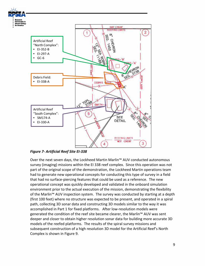
The Part 1 operations were successfully completed on July 20, 2011, and the Lockheed Martin team disembarked while Chevron performed other activities over the next 11 days. The Lockheed Martin team re-embarked on August 1, 2011, and started conducting survey missions of an artificial reef site EI-338. This site consisted of five reefed platforms located on the seafloor with a debris field in between. This artificial reef site is shown in Figure 7.
9
Figure 7- Artificial Reef Site EI-338
Over the next seven days, the Lockheed Martin Marlin™ AUV conducted autonomous survey (imaging) missions within the EI 338 reef complex. Since this operation was not part of the original scope of the demonstration, the Lockheed Martin operations team had to generate new operational concepts for conducting this type of survey in a field that had no surface-piercing features that could be used as a reference. The new operational concept was quickly developed and validated in the onboard simulation environment prior to the actual execution of the mission, demonstrating the flexibility of the Marlin™ AUV inspection system. The survey was conducted by starting at a depth (first 100 feet) where no structure was expected to be present, and operated in a spiral path, collecting 3D sonar data and constructing 3D models similar to the way it was accomplished in Part 1 for fixed platforms. After low-resolution models were generated the condition of the reef site became clearer, the Marlin™ AUV was sent deeper and closer to obtain higher resolution sonar data for building more accurate 3D models of the reefed platforms. The results of the spiral survey missions and subsequent construction of a high resolution 3D model for the Artificial Reef’s North Complex is shown in Figure 9.
Figure 8 - 3D Models Constructed of Artificial Reef Site EI-338 (North Complex)
The RPSEA Phase II GoM technology validation demonstration ended on August 7, and the Lockheed Martin AUV system was de-mobilized on August 8, 2012, bringing an end to an extremely successful demonstration of a platform inspection capability using the Lockheed Martin Marlin™ AUV inspection system.
2.0 GULF OF MEXICO DEMONSTRATION SUMMARY OF RESULTS This section of the report provides a daily summary of the events that took place during both parts of the RPSEA Phase II technology validation demonstration conducted in partnership with Chevron under RPSEA contract 09121-3300-05.
2.1 Part 1: Fixed Platform Inspection Demonstration (July 5 - 20, 2011) During this portion, the Lockheed Martin Marlin™ AUV inspection system was mobilized onboard the Abdon Callais M/V Jessica Moore and performed various missions and sorties around two non-operational fixed oil and gas platforms in the Gulf of Mexico. The two platforms that were utilized for this portion of the demonstration were an eight-pile platform (Chevron #1) and a four-pile platform (Chevron #2). Both of these platforms are owned by Chevron and are shown in Figure 9.
Figure 9 - Chevron Platform #1 (Left) and #2 (Right)
11
2.1.1 Days 1 - 4 (July 5 - 8): Installation and Checkout of Lockheed Martin Marlin™ AUV System The Lockheed Martin team arrived at the Abdon Callais shipyard on July 5, 2011, and mobilization activities began. Over the next four days, the equipment was placed and secured to the deck and cabling was routed between the deck generator, operations and maintenance van and the Marlin™ AUV launch and recovery knuckleboom crane. The launch and recovery crane was also load tested during this period and was witnessed by an inspector from the American Bureau of Shipping. Load testing of the Marlin™ AUV launch and recovery knuckleboom crane is shown in Figure 10.
Figure 10 - Load Test of Marlin™ Launch and Recovery Crane
The final pierside checkout of the Lockheed Martin Marlin™ AUV inspection system was completed on July 8, 2011, and the system was ready to begin operations on July 9, 2011. The system as configured onboard the M/V Jessica Moore is shown in Figure 11.
12
Figure 11 - Lockheed Martin’s Marlin™ AUV Underwater Facility Inspection System Mobilized onboard Abdon Callais M/V Jessica Moore
2.1.2 Days 5 - 8 (July 9 - 12): Marlin™ AUV Launch & Recover Operations On July 9, 2012, the Jessica Moore departed the pier to conduct offshore launch and recovery operations approximately five nautical miles from shore in 60 feet of water. Over the next four days, the Lockheed Martin team performed launch and recovery operations from the vessel. The purpose of this exercise was to validate the procedures for launching and recovering the Marlin™ AUV from the starboard side of the M/V Jessica Moore and give the Lockheed Martin launch and recovery crew a chance to rehearse launching and recovering the Marlin™ AUV in the actual Gulf of Mexico environment. This also provided an opportunity to train additional crane operators. During the first two days of this period, the Marlin™ AUV was launched and recovered several times without releasing the vehicle from the crane’s lift line. The launch and recovery procedures were streamlined as a result of these operations, making the launch and recovery sequence more efficient. At the end of this period, the time for overboarding and recovering the AUV back to the cradle was less than 15 minutes. Figure 12 shows the Marlin™ vehicle being launched and recovered from the M/V Jessica Moore.
13
Figure 12 – Marlin™ AUV Launch & Recovery
On the last two days of this period (July 11 - 12, 2011), a complete normal launch and recovery cycle was successfully accomplished, including release of the vehicle. The vehicle was removed from its deck cradle, maneuvered over the side, placed into the water, and released from the capture line. The vehicle was submerged and maneuvered away from the ship via operator manual commands followed by an automatic capture of the crane’s lift line by the Marlin™ AUV. During this sequence (patent pending), the vehicle autonomously homed in on the lift line which was equipped with an acoustic transponder and captured the line autonomously without any operator input. This automatic capture was done at a depth of approximately 45 feet. Once the vehicle captured the lift line, the vehicle was winched in, snubbed to the crane, and then maneuvered back into its deck cradle. A manual recovery sequence was also conducted on these last two days.
In the event that the vehicle is not able to autonomously home in and capture the lift line, the vehicle will be surfaced and the crane’s recovery hook manually attached (using a long pole from deck of the vessel) to the lifting clevis located on top of the vehicle. Once the lift line hook is attached, the vehicle is recovered in the same manner as for a normal recovery.
Figure 13 shows a manual capture of the vehicle underway.
14
Figure 13 – Manual Capture of Marlin™ AUV
After the Lockheed Martin launch and recovery demonstrations were completed, the ship returned to Port to allow for Chevron to mobilize their equipment.
2.1.3 Days 9 - 10 (July 13 - 14): Chevron Mobilization Over the next two days Chevron mobilized equipment for operations unrelated to the Lockheed Martin demonstration. There were no Lockheed Martin Marlin™ operations conducted over these two days. The ship departed at 2200 on July 14 for Chevron Platform #1, which was the first offshore platform to be inspected by the Marlin™ AUV system.
2.1.4 Day 11 (July 15): Platform Model Building Runs (Chevron Platform GI-37-GG) The M/V Jessica Moore arrived at the first fixed oil and gas platform to be inspected by the Lockheed Martin AUV system. This platform was a Chevron-owned asset (#1), which was an eight- pile platform located in approximately 55 feet of water. This platform is shown in Figure 14.
15
Figure 14 – Arrival at Chevron Platform #1 (8 pile platform in 55 feet of water)
The first autonomous mission that was conducted on Chevron Platform #1 was a model-building mission, since no previous information (drawings or 3D models) about the platform existed. During this mission, the Marlin™ AUV autonomously circled the platform on a pre-planned mission at various standoff distances from the platform ranging from 50 meters to as close as 15 meters and at various depth slices in order to scan the entire height of the platform. The collected imagery of the platform using the Marlin™ onboard CodaOctopus Echoscope sonar was then used to construct a high-resolution 3D model of the platform via post processing of the data using a Lockheed Martin developed analysis tool. The resulting high-resolution 3D models from these scans, generated in one to two hours, are shown in Figure 15. The left side of the figure shows a high-resolution version of the constructed model that is colored by depth. The right side of the figure shows the same model after additional post processing which adds a skin to the structural members. Both models were created from sonar imagery data that was collected during the 15-meter offset runs.
Figure 15 – Results from Model Building Mission for Platform #1 at 15m Offset
2.1.5 Day 12 - 13 (July 16 - 17): Platform Inspection Runs (Chevron Platform #1) The first platform inspection run was conducted on July 16, 2011. For this run, anomalies were incorporated into the 3D model that was constructed from the model-
16
building runs completed previously. Working closely with Chevron, various anomalies were incorporated into the 3D model and were representative of damage that might be expected to occur to a platform, including a bent member, a missing member and a buckled member. This altered 3D model then became the base (a-priori) model that was used as the basis for comparison during subsequent inspection runs. The altered 3D model was loaded into the Marlin™ AUV, and an inspection mission was conducted at 15-meter offset from the platform at increasing depth slices until the entire platform was imaged. The scanned imagery was compared to the base model and changes were automatically detected, highlighted, and localized in real-time. Figure 16 shows the results of the autonomous inspection mission around Platform #1. The left side of the figure shows the base (a-priori) model that was altered with anomalies, and the right side of the figure shows the imagery from the follow-on inspection mission overlayed on the base model with the changes highlighted with red and blue boxes, depending on whether it was a positive change (something that should not be there that is) or a negative change (something that should be there that is not).
Figure 16 – Results from Platform Inspection Mission for Platform #1 with Anomalies Detected
After completing an additional set of inspection runs of Chevron Platform #1, the M/V Jessica Moore departed for the second platform to be inspected, Chevron Platform #2, with the Lockheed Martin Marlin™ AUV system.
2.1.6 Day 14 (July 18): Platform Model Building Runs (Chevron Platform #2) The vessel arrived at the second fixed oil and gas platform to be inspected by the Lockheed Martin AUV system on July 18, 2012. This platform was a Chevron-owned asset, Platform #2, which was a four-pile platform located in approximately 130 feet of water. This platform is shown in Figure 17.
BuckledMember
BentMember
MissingMember
All AnomaliesDetected
17
Figure 17 – Arrival at Chevron Platform #2 (4 pile platform in 130 feet of water)
Similar to what was done on Platform #1, the first autonomous mission conducted on this platform was a model-building mission, since no previous information (drawings or 3D models) about the platform existed. During this mission, the Marlin™ AUV autonomously circled the platform on a pre-planned mission at various standoff distances from the platform that ranged from as far away as 50 meters to as close as 10 meters and at various depth slices in order to scan the entire height of the platform. The collected imagery of the platform using the Marlin™ onboard CodaOctopus Echoscope 3D sonar was then used to construct a high resolution 3D model of the platform via post-processing of the data using a Lockheed Martin developed analysis tool. The resulting high-resolution 3D models from these scans are shown in Figure 18. The left side of the figure shows a high resolution version of the constructed model that is colored by depth. The right side of the figure shows the same model after additional post processing, which adds a skin to the structural members. Both models were created from sonar imagery data that was collected during the 15-meter offset runs.
Figure 18 - Results from Model Building Mission for Platform #2 at 15m Offset
18
2.1.7 Day 15 (July 19): Platform Inspection Runs (Chevron Platform EI-237) The first platform inspection run on Platform #2 was conducted on July 19, 2012. For this run, anomalies were incorporated into the 3D model that was constructed from the previous model building missions. Several different sized and shaped anomalies were incorporated into the model, ranging in size from one cubic foot to one cubic meter in open and encumbered space around the platform. This model became the base (a-priori) model that was used as the basis for comparison during additional inspection runs. The altered model was loaded into the Marlin™ AUV, and an inspection mission was conducted at 15-meter offset from the platform at increasing depth slices until the entire platform was imaged. The scanned imagery was compared to the base model and changes were automatically detected, highlighted, and localized in real-time. Figure 19 shows the results of the autonomous inspection run for the one cubic meter anomalies. The left side of the figure shows the base (a-priori) model that was altered with anomalies, and the right side of the figure shows the imagery from the subsequent inspection mission overlayed on the base model with the changes highlighted with blue boxes indicating a negative change (something that should be there that is not). Note that all of the changes were detected as negative changes because the anomalies were added to the base (a-priori) model. Since the actual platform that was imaged by the Marlin™ AUV did not contain these anomalies, they were detected as something that was not part of the structure that should have been.
Figure 19 - Results from Platform Inspection Mission for Platform #2 with Anomalies Detected
A similar mission was conducted using a base (a-priori) model that included one cubic foot anomalies. All of these anomalies were detected as well during a subsequent inspection mission.
2.1.8 Day 16 (July 20) Platform Inspection Demonstration On the last day of the first portion of trials, Lockheed Martin conducted a complete end-to-end demonstration of the Marlin™ AUV inspection system’s capability for Chevron on
19
Platform #2. During this demonstration, the Marlin™ AUV system went through a normal platform inspection operational scenario, starting with pre-mission operations. This included planning and downloading the mission to vehicle and checkout of the Marlin™ AUV system prior to launch. Following the pre-mission operations, the Marlin™ AUV was launched overboard and released from the crane. To start the inspection mission, the Marlin™ AUV operator selected the “Start Mission” button on the user interface window, and the vehicle began executing a full autonomous inspection mission including ingress to the platform, acquisition of the platform, and inspection of the platform at a 15-meter standoff distance at various depth steps in order to complete a full top to bottom inspection of the platform. Once the inspection was completed, the Marlin™ AUV egressed to the recovery location holding both position and depth until the lift line from the crane (with acoustic transponder) was lowered into the water. The Marlin™ AUV operator then selected the “Recover” button on the user interface window, and the vehicle autonomously homed in on and captured the lift line. The Marlin™ AUV was recovered onboard by winching in on the knuckleboom crane until the vehicle was snubbed tightly to the crane. The crane operator then maneuvered and lowered the vehicle into the deck cradle. Post mission operations were conducted, including fresh water washdown of the vehicle and offload of the inspection mission data that included a re-constructed image of the scanned platform overlaid on the base (a-priori) model with changes (anomalies) highlighted (similar to figure 19). This model was generated on the vehicle in real-time during the inspection mission and was immediately available after offloading the data (i.e., no post-processing was required).
2.1.9 Chevron Specific Operations (July 21-31) Following Part 1 operations, The Lockheed Martin team disembarked to allow Chevron to accomplish other objectives over an 11-day period (July 21 - 31, 2011). The Lockheed Martin team re-embarked on July 31, 2011, to begin Part 2 operations.
2.2 Part 2: Artificial Reef Site Survey (August 1 - 8, 2011) During this eight-day portion, the Marlin™ AUV inspection system was used to conduct surveys of various reefed platforms that were scattered along the bottom of the ocean floor within reef complex EI-338. This site contained three platforms on the north side of the reef complex, two platforms on the south side, and a debris field in between. Since this operation was not part of the original scope of the demonstration, the Lockheed Martin team had to generate new operational concepts for conducting a survey in a field with no surface-piercing structures that could be used as a reference. The new operational concept was developed rather quickly by the Lockheed Martin operations team and tested in the onboard simulation environment within the operations van before actual execution of the mission. This quick adaptation to a changing environment demonstrated the flexibility of the Marlin™ AUV inspection system. The artificial reef complex that was utilized for this survey is in approximately 265 feet of water and is shown in Figure 20.
20
Figure 20 - Artificial Reef Complex EI-338
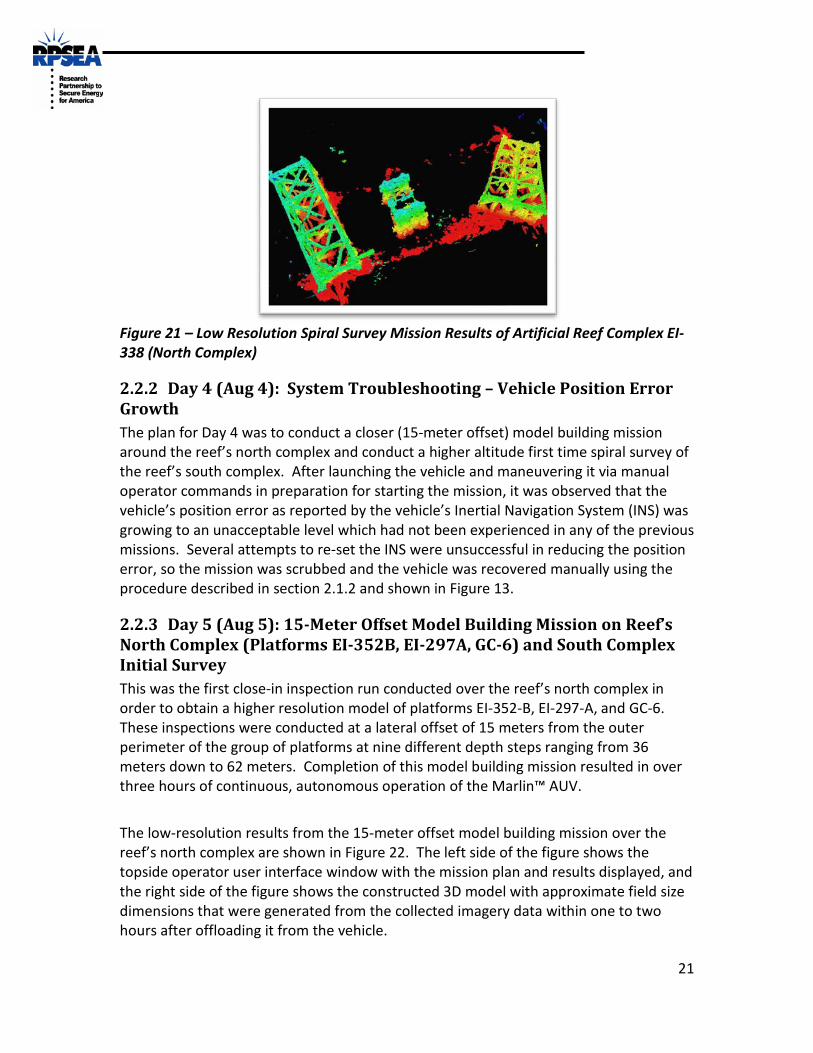
2.2.1 Days 1 - 3 (Aug 1 - 3): Initial Survey and Model Building Missions for Reef EI 338 (North Complex, Debris Field) Since no previous information was known about the reefed structures, other than what is shown in Figure 20, the first autonomous mission that was conducted was a model building mission over the reef’s north complex containing platforms EI-352-B, EI-297-A and GC-6. During this mission, the Marlin™ AUV autonomously circled high above the reefed platforms in a spiral pattern at a depth (first 100 feet) that was considered safe and free of structures. Once the mission was completed, the vehicle was surfaced and the imagery was offloaded via Marlin™ Radio Frequency (RF) link. A low-resolution model of the area was then constructed in a similar fashion as the fixed platform model building process. Once confidence was established that there was no other structure in the path of the Marlin™ AUV based on the low-resolution model of the area, the spiral surveys were conducted deeper and closer to the reefed platforms to obtain higher resolution sonar imagery and construct higher resolution 3D models. The spiral surveys continued on Days 2 and 3 over the reef’s North complex and debris field. The low-resolution 3D model that was constructed from the initial spiral survey mission over the reef’s north complex is shown in Figure 21.
Figure 21 – Low Resolution Spiral Survey Mission Results of Artificial Reef Complex EI-338 (North Complex)
2.2.2 Day 4 (Aug 4): System Troubleshooting – Vehicle Position Error Growth The plan for Day 4 was to conduct a closer (15-meter offset) model building mission around the reef’s north complex and conduct a higher altitude first time spiral survey of the reef’s south complex. After launching the vehicle and maneuvering it via manual operator commands in preparation for starting the mission, it was observed that the vehicle’s position error as reported by the vehicle’s Inertial Navigation System (INS) was growing to an unacceptable level which had not been experienced in any of the previous missions. Several attempts to re-set the INS were unsuccessful in reducing the position error, so the mission was scrubbed and the vehicle was recovered manually using the procedure described in section 2.1.2 and shown in Figure 13.
2.2.3 Day 5 (Aug 5): 15-Meter Offset Model Building Mission on Reef’s North Complex (Platforms EI-352B, EI-297A, GC-6) and South Complex Initial Survey This was the first close-in inspection run conducted over the reef’s north complex in order to obtain a higher resolution model of platforms EI-352-B, EI-297-A, and GC-6. These inspections were conducted at a lateral offset of 15 meters from the outer perimeter of the group of platforms at nine different depth steps ranging from 36 meters down to 62 meters. Completion of this model building mission resulted in over three hours of continuous, autonomous operation of the Marlin™ AUV.
The low-resolution results from the 15-meter offset model building mission over the reef’s north complex are shown in Figure 22. The left side of the figure shows the topside operator user interface window with the mission plan and results displayed, and the right side of the figure shows the constructed 3D model with approximate field size dimensions that were generated from the collected imagery data within one to two hours after offloading it from the vehicle.
22
Figure 22 – Low Resolution Results from 15M Offset Model Building Mission of Reef’s North Complex
Additional post-processing of this data using Lockheed Martin-developed model-building tool resulted in a higher resolution constructed model of platform EI-352-B as shown in Figure 23.
Figure 23 – High Resolution 3D Model of North Complex, Platform EI-352-B
An initial spiral survey over the reef’s south complex (SM174-A, EI-330A) was accomplished next in a similar fashion as the north complex. The constructed model from the initial spiral survey mission over the reef’s south complex is shown in figure 24. The left side of the figure shows the topside operator user interface window with the spiral mission results displayed, and the right side of the figure shows the constructed 3D model that was generated within one to two hours after offloading the data from the vehicle.
23
Figure 24 – Spiral Survey Mission Results Over Reef Complex EI-338 (South Complex)
2.2.4 Day 6 (Aug 6): System Troubleshooting – Actuator Pressure Compensator Oil Leak The plan for Day 6 was to conduct a closer (15-meter offset) model-building mission around the reef’s south complex to obtain a higher resolution 3D model. After delays in the morning with resolving an issue with large INS position uncertainty errors, the vehicle was launched at 1300. Shortly thereafter the Lockheed Martin team discovered oil near and around the vehicle’s deck cradle. Suspecting that there may be a leak in one of the seven actuator pressure compensators on the vehicle, the mission was aborted and the vehicle recovered back to the cradle for troubleshooting. It was quickly determined that an o-ring was missing from the compensator circuit vent port fitting for the aft port fin actuator. This actuator was provided by the vendor as a loaner for the Gulf of Mexico trials and apparently, was delivered without the o-ring installed, which was not discovered until the leak occurred. Since this actuator was provided to Lockheed Martin as a loaner, this was considered an isolated occurrence.
2.2.5 Day 7 (Aug 7): 30-Meter Offset Model Building Mission on Reef’s South Complex (Platforms SM-174-A, EI-330-A) This was the last mission that was conducted as part of the Gulf of Mexico trials and was the first close-in inspection run conducted over the reef’s north complex in order to obtain a higher resolution model of platforms SM-174-A and EI-330-A. These inspections were conducted at a lateral offset of 30 meters from the outer perimeter of the group of platforms at six different depth steps that ranged from 25 meters down to 75 meters.
The vessel returned to the port and the Marlin™ AUV inspection system was de-mobilized concluding an extremely successful technology validation demonstration of a platform survey and inspection capability using the Lockheed Martin’s Marlin™ AUV inspection system. The Lockheed Martin (light blue shirts) and Chevron teams that participated in these trials are shown in Figure 25.
24
Figure 25 - Conclusion of 2011 Summer Gulf of Mexico Trials (Lockheed Martin and Chevron Teams Pictured with Lockheed Martin’s Marlin™ AUV)
3.0 POST GOM TRIAL ANALYSIS OF DATA After the Gulf of Mexico demonstration trials were completed, the Lockheed Martin team performed an additional analysis of the data in order to determine the accuracy of the 3D models that were constructed from the model-building runs that were conducted on Chevron Platform #2. Although a computer-generated 3D model was not available at the time of the trials, a set of blueprints for this platform was obtained after the trials were completed. From these blueprints, Lockheed Martin constructed a 3D CAD model of the platform that was used for comparison to the data collected during the trials.
A comparison of the features depicted on the 3D constructed model with the CAD model was completed resulting in very good correlation including clearly visible anodes and separation between the seafloor and bottom structural member. These results are shown in Figure 26.
25
Figure 26 – Feature Comparison (CAD Model vs. Constructed Model from Trials)
Another analysis that was completed was to overlay the 3D model that was constructed over the CAD model. Once again, there was a very close correlation between the two as shown in figure 27. The CAD model is shown in green, and the gray represents the 3D model that was constructed from the model-building runs at a 10-meter offset.
Figure 27 – Comparison of CAD Model with 3D Constructed Model for Chevron Platform #2
Currently, the construction of the 3D models that is accomplished post-mission is labor intensive, requiring a fair amount of manual manipulation. As part of further research and development in 2012, Lockheed Martin plans to automate this process in order to reduce the amount of time it will take to construct a 3D model after the data is offloaded.
26
4.0 CONCLUSION The extreme success of the 2011 Gulf of Mexico trials has clearly demonstrated that conducting surveys and/or inspections of offshore oil and gas infrastructure is viable using AUVs. During the 2011 trials, the Lockheed Martin Marlin™ AUV system was demonstrated to be a very capable system for this application by showing that a platform can be inspected in a very short period of time (less than one hour for each of the two platforms inspected) as compared to a similar mission using a remotely operated vehicle. Over a period of six operational days, the Lockheed Martin Marlin™ AUV completed inspections of two surface-piercing fixed oil and gas platforms (Chevron Platforms #1 and #2), resulting in high resolution 3D models of the platforms being constructed when no other information was available. This type of information is useful for determining if there are any visible large scale structural defects or assisting with platform de-commissioning plans or activities. Further, it was demonstrated that if a base (a-priori) model of the platform exists, the Lockheed Martin Marlin™ AUV will automatically detect and highlight large scale (greater than one cubic foot) anomalies by re-constructing the model from the sonar imagery during the inspection mission, comparing it to the base (a-priori) model and highlighting changes to the operator, all in real-time without any additional post-processing required. During the development of this platform inspection technology, Lockheed Martin has advanced the Technology Readiness Level from a TRL 2 to a TRL 5 over a two-year period that culminated in this very successful demonstration.