UNCLASSIFIED MASTER COPY .e1f~ F R~~PURPOSES SEURBITY CLAWICIAMIN OF YP115 BIC E r, DOCUMENTATION PAGE I& RPORTSECRITYCIAFCATONlb. RESTRICTIVE MARKINGS SECUITY LASSFICAION3. DiSTRIGUTION/AVAILAIITY OF REPORT 1b. 9CLASIF T*NDOWW , Approved for public release; distribution unlimited. 00L PERFORMING ORGANIZATION REPORT NUMU9) S. MONITORING ORGANIZATION REPORT NUMBER(S) N wARO 26372.1-MS-CF In J .a. NAME Of PERFORMING ORGANIZATION 6b. OFFICE SYMBOL 7a. NAME OF MONITORING ORGANIZATION Vi n a ltecnic nt.W~p~b@ U. S. Army Research Office N c. ADDRESS (Clip. Stae, &Wd ZPCo*j 7b. ADDRESS (Clip. Stae, and ZIP Co) Blackburg VA 4061P. 0. Box 12211 Blackburg VA 4061Research Triangle Park, NC 27709-2211 ~ .NAME OF FUNDING/iSPONSORING 8 b. OFFICE SYMBOL 9. PROCUREMENT INSTRUMENT IDENTIFICATION NUMBER ORGANIZATION (pifct"~) DAAL3-88-G-0043 SU. S. Army Research Office ADDRESS (ClRY, State and ZPCodu) 10. SOURCE OF FUNDING NUMB._RS F. 0. Box 12211 PROGRAM 1PROJECT ITASU WORK UNIT Aesearch Triangle ParkN 27709-2211 ELEMENT NO. NO. [O. rEssioN No. 11. TITLE (knc*#* Sectw~pflctl Smart Materials, Structures and Mathematical Issues 12. PERSONAL AUTHORMS _l~o . Rnapern (Princinal Investiaator on Proliect) 13a. TYPE OF REPORT [13b. TIME COVERED 11.DTE OF REPORT (Year MA, Day) IS. PAGE COUNT Final I RM8888 T LZL_9 199r 16. SUPPLEMENTARY NOTATION The view, opinions and/or findings contained in this report are those of. he authgr ) and sh uld not be construld as an ffcaq un f the Army position, 17. COSATI CODES 18. SUBJECT TERMS (Conuinu. on mwnw ff neceuuy ed ilentift by block numbe) FIELD GOP SUB-GROUP Smart Materials, Smart Structures, Actuators, Sensors, Intelligence, Control, Constitutive Modeling '9. ABSTRACT (Continue an reserus N necesaty end Idmntd by black nwanbeul This workshop on Smart Materials, Structures, and Mathematical Issues i's one of a series of workshops organized by the U. S. Army Research Office to identifiy recent significant developments and breakthroughs in science and technology. Its main objective is to evolve a consensus on the definition and characteristics of a Ismart'/'intelllgent' material or structure, and discuss mechanisms and possible methods to produce them. Another objective is to identify directions of future re- search in this field. This report includes the abstracts/papers presented at the three sessions. The three sessions related to (1) Smart Structures, (2) Smart Materials, and (3) Related Mathematical Issues, contain a wide range of presentations concerning numberous technologies for actuators, sensors, intelligence, (CONT'D ON BACK) L20. DISTRIBUTION I AVAILAUIUT OF ABSTRACT 21. ABSTRACT SECURITY CLASSIFICATION O~UNCLASSoFDANmITED C3 SAME As Rw. D OTIC USERS Unclassified 22a. NAME OF RESPONSBE INDIVIDUJAL 22b. TILEPI4ONE (kwklud Area Code) I22c. OFFICE SYMBOL 00 FOM 1473,8 M dA S APR edition may be used until othaaweed. SECURITY CLASSIFICATION OF THIS PAGE All othe editions are obsolete. UCASFE
Transcript
UNCLASSIFIED MASTER COPY .e1f~ F R~~PURPOSESSEURBITY CLAWICIAMIN OF YP115 BIC E
SECUITY LASSFICAION3. DiSTRIGUTION/AVAILAIITY OF REPORT
1b. 9CLASIF T*NDOWW , Approved for public release;distribution unlimited.
00L PERFORMING ORGANIZATION REPORT NUMU9) S. MONITORING ORGANIZATION REPORT NUMBER(S)
N wARO 26372.1-MS-CFIn J
.a. NAME Of PERFORMING ORGANIZATION 6b. OFFICE SYMBOL 7a. NAME OF MONITORING ORGANIZATION
Vi n a ltecnic nt.W~p~b@ U. S. Army Research Office
N c. ADDRESS (Clip. Stae, &Wd ZPCo*j 7b. ADDRESS (Clip. Stae, and ZIP Co)
Blackburg VA 4061P. 0. Box 12211Blackburg VA 4061Research Triangle Park, NC 27709-2211
~ .NAME OF FUNDING/iSPONSORING 8 b. OFFICE SYMBOL 9. PROCUREMENT INSTRUMENT IDENTIFICATION NUMBERORGANIZATION (pifct"~) DAAL3-88-G-0043
SU. S. Army Research OfficeADDRESS (ClRY, State and ZPCodu) 10. SOURCE OF FUNDING NUMB._RS
F. 0. Box 12211 PROGRAM 1PROJECT ITASU WORK UNIT
Aesearch Triangle ParkN 27709-2211 ELEMENT NO. NO. [O. rEssioN No.
11. TITLE (knc*#* Sectw~pflctl
Smart Materials, Structures and Mathematical Issues
12. PERSONAL AUTHORMS_l~o . Rnapern (Princinal Investiaator on Proliect)
13a. TYPE OF REPORT [13b. TIME COVERED 11.DTE OF REPORT (Year MA, Day) IS. PAGE COUNTFinal I RM8888 T LZL_9 199r
16. SUPPLEMENTARY NOTATION The view, opinions and/or findings contained in this report are thoseof. he authgr ) and sh uld not be construld as an ffcaq un f the Army position,
17. COSATI CODES 18. SUBJECT TERMS (Conuinu. on mwnw ff neceuuy ed ilentift by block numbe)FIELD GOP SUB-GROUP Smart Materials, Smart Structures, Actuators, Sensors,
Intelligence, Control, Constitutive Modeling
'9. ABSTRACT (Continue an reserus N necesaty end Idmntd by black nwanbeul
This workshop on Smart Materials, Structures, and Mathematical Issues i's one ofa series of workshops organized by the U. S. Army Research Office to identifiy recentsignificant developments and breakthroughs in science and technology. Its mainobjective is to evolve a consensus on the definition and characteristics of aIsmart'/'intelllgent' material or structure, and discuss mechanisms and possiblemethods to produce them. Another objective is to identify directions of future re-search in this field.This report includes the abstracts/papers presented at the three sessions.The three sessions related to (1) Smart Structures, (2) Smart Materials,and (3) Related Mathematical Issues, contain a wide range of presentationsconcerning numberous technologies for actuators, sensors, intelligence,
(CONT'D ON BACK)L20. DISTRIBUTION I AVAILAUIUT OF ABSTRACT 21. ABSTRACT SECURITY CLASSIFICATION
O~UNCLASSoFDANmITED C3 SAME As Rw. D OTIC USERS Unclassified22a. NAME OF RESPONSBE INDIVIDUJAL 22b. TILEPI4ONE (kwklud Area Code) I22c. OFFICE SYMBOL
00 FOM 1473,8 M dA S APR edition may be used until othaaweed. SECURITY CLASSIFICATION OF THIS PAGEAll othe editions are obsolete. UCASFE
UNCLASSIFIEDISMUYTY CLMICAW IM OF T18 PA4 ,_..._ _ _ _
.)control, constitutive modeling, and other scientific fields that havebecome essential to the emerging science and technologies of smartmaterials and structures. At the end of each session a discussionperiod was held to address some of issues of general concern relatedto the mission of the workshop.
Editor:C. A. RogersSmart Materials & Structures LaboratoryMechanical Engineering DepartmentVirginia Polytechnic Institute and State University
90 02 26 0464
"The views, opinions, and/or findings contained in this report are those of theauthor(s) and should not be construed as an official Department of the Army position,policy, or decision, unless so designated by other documentation."
, _to
Accession ForNTIS GRA&I R'
DTIC TAB 0Unannounced 0Justiflcetion
ByDiatribution/
Availability Codes
lAvail and/orDist special
U. S. Army Research Office Workshop"Smart Materials, Structures, and Mathematical Issues"
FORWARD
This workshop on "Smart Materials, Structures, and Mathematical Issues" is one ofa series of workshops organized by the U. S. Army Research Office to identify recentsignificant developments and breakthroughs in science and technology. Its mainobjective is to evolve a consensus on the definition and characteristics of a"smart'/'intelligent' material or structure, and discuss mechanisms and possiblemethods to produce them. Another objective is to identify directions of future re-search in this field.
In the following pages the abstracts/papers as received by the invited speakers arepresented. The three sessions related to i) Smart Structures, ii) Smart Materials, andiii) Related Mathematical Issues, contain a wide range of presentations concerningnumerous technologies for actuators, sensors, intelligence, control, constitutivemodeling, and other scientific fields that have become essential to the emerging sci-ence and technologies of smart materials and structures. At the end of each sessiona discussion period has been scheduled to address some of issues of general con-cern related to the mission of the workshop. It is hoped that all in attendance willcontribute to the discussion and share with all of us your impressions, experiencesand desires for the future of smart materials and structures research.
Craig Rogerslqbal AhmadWorkshop Co-chairman
U. S. Army Research Office Workshop"Smart Materials, Structures, and Mathematical Issues"
Donaldson Brown Continuing Education CenterVirginia Polytechnic Insitute and State University
Blacksburg, Virginia 24061September 15-16, 1988
Workshop Co-chairman:Dr. Iqbal Ahmad, ARO
Dr. Craig A. Rogers, VPI&SU
* Wednesday September 14, 1988
a 6:00 PM - 7:00 PM Registration and Reception at the Donaldson Brown Con-tinuing Education Center
* Thursday September 15, 1988 - Conference Room F
@ 8:00 AM - 8:30 Coffee and Danish (Registration)
a 8:30 AM - 8:50 Opening Remarks - Conference Room F
& Prof. Craig A. Rogers, VPI&SU : Workshop Cc-Chairman
4L Dr. F. W. Stephenson, Assoc. Dean - College of Engineering, VPI&SU
& Dr. lqbal Ahmad, ARO : Workshop Co-Chairman
a Session 1 - Smart Structures - Chair. Dr. Gary Anderson, ARO
* 8:50 - 9:15 'Dynamic Control Concepts Using Shape Memory Alloy Rein-forced Plates", Prof. C. A. Rogers, VPI&SU
* 9:15 - 9:40 "Optical Fiber Sensors and Signal Processing for Smart Mate-rials and Structures Applications', Prof. R. 0. Claus, VPI&SU
* 9:40 - 10:05 'A New Generation of Revolutionary Ultra-Advanced Intelli-gent Composite Materials Featuring Electro-Rheological Fluids", Prof. M.V. Gandhi, Michigan State Univ.
A 10:05 - 10:20 Coffee Break
* 10:20 - 10:45 "Plezoceramic Devices and PVDF Films as Sensors andActuators for Intelligent Structures', Prof. S. Hanagud, GA Tech
& 10:45 - 11:10 "Variable Geometry Trusses', Prof. H. H. Robertshaw,VPI&SU
* 11:10 - 11:35 'Passive Self-Adaptive Structures', Prof. E. Rivin, WayneState University
* 11:35 - 12:00 'Applications for Smart Materials in the Field of VibrationControl", Dr. T. G. Duclos, Lord Corporation
* 12:00 - 12:30 Discussion - Moderator: Dr. G. Anderson, ARO
* 12:30 - 1:30 PM Lunch at CEC
a Session 2 - Smart Materials - Chair: Dr. lqbal Ahmad, ARO
* 1:30 - 1:50 "Materials Issues for Smart Structures, Prof. G. L. Wilkes,VPI&SU
A 1:50 - 2:30 "Smart Ceramics", Prof. R. E. Newnham, Penn State Univ.
* 2:30 - 3:30 "Self Assembly and 'Smart Materials"', Dr. B. B. Rath, NavalResearch Laboratory
A 3:00 - 3:15 Coffee Break
L 3:15 - 3:45 "Basic Principles for the Improvement of Shape-Memory andRelated Materials", Prof. James, Univ. of Minnesota
* 3:45 - 4:15 "Tribopolymerization: A New Concept of Boundary Lubri-cation', Prof. M. J. Furey, VPI&SU
* 4:15 - 5:00 Discussion - Moderator: Dr. I. Ahmad, ARO
* 6:00 - 7:00 Reception
* 7:00 - Dinner at CEC - Speaker: Dr. James Robertson, C. P. Miles Professorof History, VPI&SU - "THE AMERICAN PRESIDENCY: WHAT WE WANT ANDWHAT WE GET"
. 0Friday September 16, 1988
a 8:00 - 8:30 Coffee and Danish - Conference Room B
a Session 3 - Mathematical Issues - Chair: Dr. Julian Wu, ARO
A 8:30 - 9:00 "Extremal Composites and Structural Optimization", Prof. R.V. Kohn, Courant Institute
* 9:00 - 9:30 "Wave Propagation in Layered Elastic Media", Prof. R.Rostamian, Univ. of Maryland
* 9:30 - 10:00 "Optimization and Homogenization for Elastic Materials', W.W. Hager, University of Florida
* 10:00 - 10:15 Coffee Break
* 10:15 - 10:45 "Computational Results for Phase Transitions in ShapeMemory Materials, Prof. M. Luskin, Univ. of Minnesota
* 10:45 - 11:15 "Dynamics of Phase Transitions', Prof. M. Slemrod, Univ. ofWisconsin-Madison
* 11:15 - 11:30 Discussion - Moderator: Dr. J. Wu, ARO
6 Session 4 - Direction of Future Research - Chair. Dr. Chandra
A 11:30 - 12:30 Panel Discussion - Moderator: Dr. Chandra, ARO
d 12:30- Lunch & End of Workshop
2
"SMART" STRUCTURES AND MATERIALS
I. AHMAD
U.S. Army Research Office, Research Triangle Park, NC
ABSTRACT
The definition of 'smart' and the characteristics of 'smart' structures andmaterials are reviewed.
As Professor Rogers has stated, the objectives of this workshop are as follows:
1. To arrive at a concensus about the definition of 'smart'/'intelligent'structures or materials.
2. Identify their characteristics.3. Discuss the logic and methodology of producing them.4. Discuss mathematical issues relating to modeling and predictive
rel ati onshi ps.
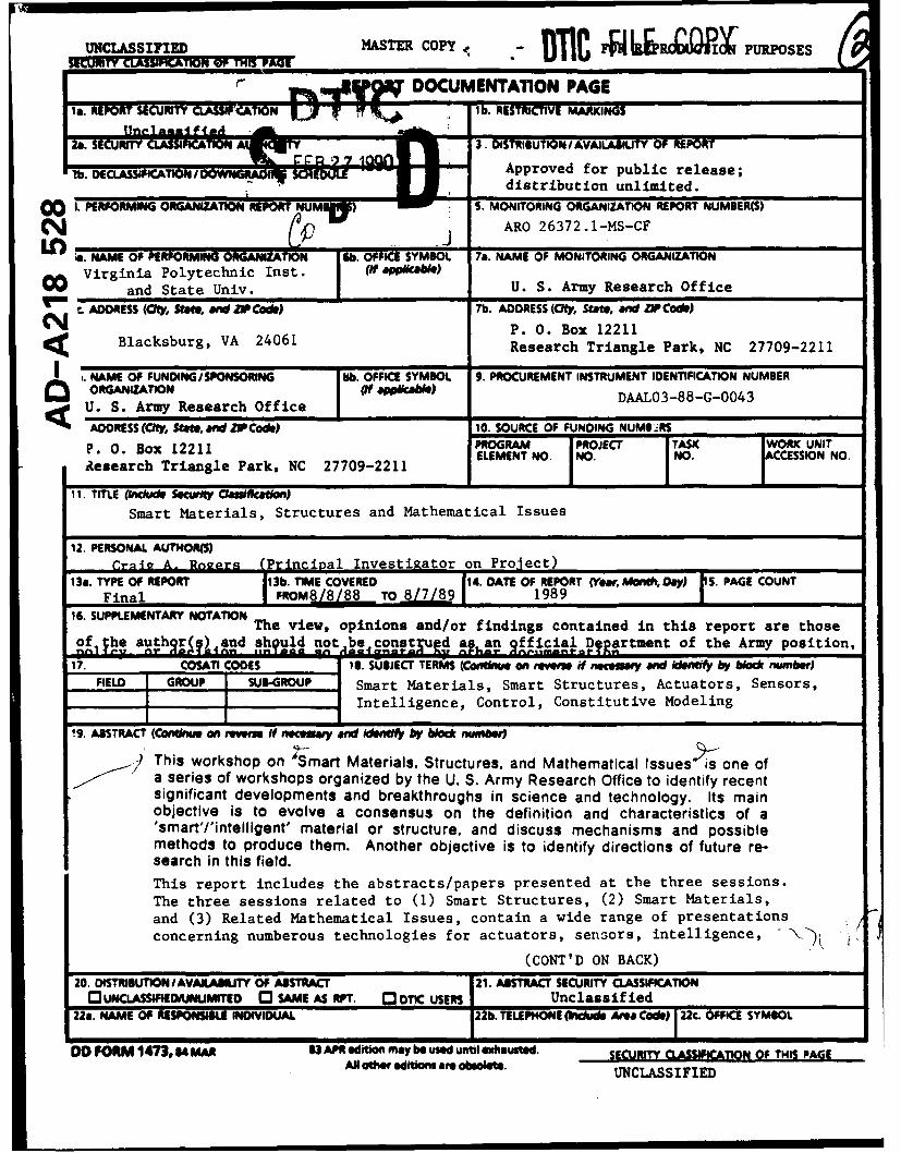
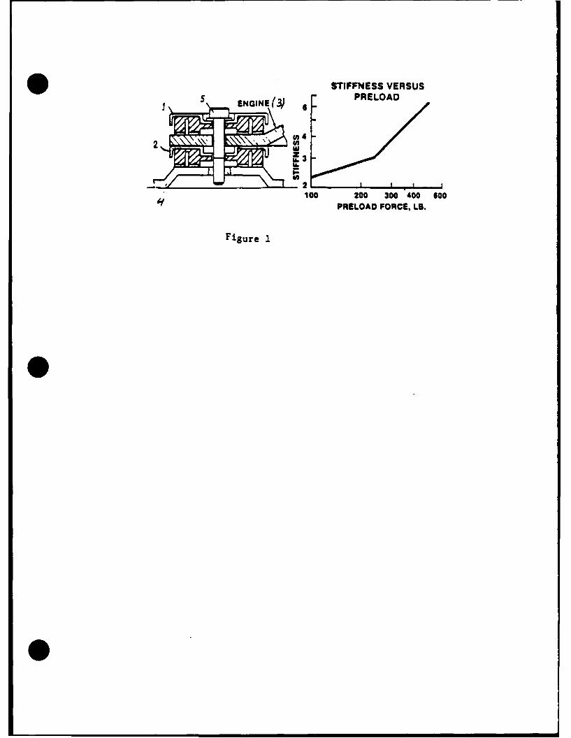
This paper is addressed to the first two objectives. The terms 'smart','adaptive' and 'intelligent' have been used recently quite frequently in the. technical meetings and literature, interchangeably and rather loosely. Forexample Professor Gandhi, who is one of the speakers at this workshop, reportsan electrorheological fluid as 'smart structural material' as it can changeproperties' on demand'. In principle this fluid is placed in a graphite epoxycomposite beam as shown in Figure 1. When an electrical potential is applied,the fluid stiffens, thereby stiffening the beam. This phenomenon can be usedto dampen vibrations in structures. Response time less than a millisecond isreported. Professor Roger, who is the co-chairman of the workshop, uses theterm 'adaptive' to shape memory alloy wires which act as actuators in acomposite beam. He has developed a system (Figure 2) in which prestrainedNitinol (an alloy of nickel and titanium) wires are embedded in an off-axisposition in the graphite fiber reinforced epoxy composite beam. When thesewires are heated by passing an electrical current they try to contract to theiroriginal length, which generates a uniformly distributed shear load along theirlength, causing the beam to bend in a predictive manner. In a recent issue ofLaser Focus (May 1988) a concept of 'smart structure' that contains embeddedf1her-optic sensors has been presented. The idea is to incorporate the sensorsat the time of the manufacture of the structure to monitor the manufacturingprocess, check the integrity of the structure before installation in the systemand monitor its health during service. The output from various sensors ismultiplexed for transition to optical/electronic preprocessors whose outputgoes to control computers. A fiber optical link can be used in connection withthe control system to activate actuators when required. So in this example,the 'smart' structure includes sensors, a control system and actuators.
. Use of piezoelectric actuators as elements of 'intelligent' structures has beenactively pursued by many researchers. In the large space structures, these
* actuators are required to control both the rigid body and elastic deformations.The feasibility of using segmented actuators for vibration and shape controlhas been demonstrated both analytically and experimentally by Crawley et al(AIAA Journal, vol 25, No. 10, p 1373-1385).
No intrinsically 'smart' or 'intelligent' material has been reported as such inthe literature. However, a carefel search does indicate a few materials, whichmay qualify as 'intrinsically' smart. In other words, they have intrinsiccapability of sensing the stimulus and responding in a controlled manner, as aresult of their atomic or molecular structure. The former is exemplified byphotochromic glass and the latter is prevelant in the biosystems. Theseexamples will be very briefly described in the following.
Photochromic glass used in the popular ophthalmic lenses for the protection ofeyes from the ultraviolet radiation, was discovered by Arimstead and Stooky ofCorning Glass in 1964. This glass has the remarkable property of becoming darkin the sunlight and reverting to the clear state indoors. This is accomplishedby incorporating in an appropriate glass composition, a small quantity of veryfine crystallites of silver chloride containing traces of copper. Figure 4shows the arrangement of ions in one of the silver chloride crystals, beforeand after darkening. The process resDonsible for darkening can be sumarizedby the following equations:
Cl + hv+ - Cl° + e (1)e + Ag = Ago (Trapped electron) (2)
Cu+ + C1° = C" + Cu++ (Trapped hole) (3)
Cu+ + Ag+ = Ag0 + Cu++ (4)
Thus the silver halide which is sensitive to the ultraviolet radiation actsboth as a sensor and as an actuator, as the darkening is the result of the
clustering of silver atoms (Ago). The fading is the reverse of reaction (4)which is energetically favorable in the absence of ultraviolet radiation.
From the biosystems a large number of examples of molecular entities, which canbe termed as 'smart' or 'intelligent' can be mentioned. One simple example(Encyclopedia Britanica, 'Science and the Future' 1981 Year Book, p 122-137) isthe cell membrane. All living beings are composed of cells which carry outspecialized functions with greatest efficiency. The life and performance ofliving systems is due to the integration of these functions. Cells themselvesare highly complex systems. They are kept separate by a thin wall called cellmembrane. Until recently cell wall was considered to be a passive systemthrough which certain constituents can pass. But more recently, the structureand function of this membrane have been elucidated, according to which it isnow believed that it is a dynamic system which controls (1) transport of rawmaterials into the cell and secretory and waste materials out of the cell, and(2) it carries specialized receptor molecules which function as sensors for the. cell and provides it with means to react with the outside stimuli such ashormones, regulatory substances such as drugs or even other cells.
2
* The cell membrane is essentially composed of phospholipid molecules which arehydrophobic on one end and hydrophilic on the other (Fig 5a). In aqueoussolutions, they form stable bilayers as shown in Figure 5(b), with the hydro-philic groups on the surface. In these layers are incorporated protein mole-cules, which consist of chains of amino acids some of which are hydrophobic andothers are hydrophilic. These molecules in aqueous solutions fold into threedimensional structures (Figure 6a) that satisfy the surface properties ofindividual amino acids. In the aqueous medium the protein chains fold in sucha way that the hydrophobic amino acids are collected together within thestructure, while the hydrophilic portions are on the surface. Although cellsuse about 20 types of amino acids, essentially any one of them can appear atany position on the protein chain which could have anywhere from 50-50,000amino acids. This provides these molecules a large number of functional capa-bilities. These chains are flexible and are quite sensitive to the conditionsthat effect chemical reactions- temperature, pressure, acidity and exposure toother molecules. Also some carbohydrate groups occur as chains attached to thephospholipid and protein molecules of the membrane, which act as sensors. Theconfiguration of the protein molecule is very sensitive to an is determined bythe chemical environment in and outside the cell. For transport of moleculessuch as glucose, the protein chain forms hydrophilic channels as shown inFigure 7. whereby the attached molecule is transported into the cell. As soonas the molecule detaches (caused by the environment in the cell interior) fromthe protein surface, the chain reconfigures into the original shape as inFigure 7a. Thus the protein molecule acts as a sensor and because of its abi-lity to configure dictated by the environment, as an actuator. Control
e mechanisms are provided by the chemical environment. The key factor is theW Intrinsic nature of the molecular structure. Other functions and the
mechanisms of transport used by the protein molecules are described in theliterature.
From the above examples, the common features of the so called 'smart' or'intelligent' structures or materials, can be identified as follows:
1. They have embedded (or bonded) or intrinsic sensor/s which recognize andmeasure the intensity of the stimulus, such as stress, strain, thermal,electric, magnetic, electromagnetic, chemical or nuclear etc.
2. They have embedded or intrinsic actuator/s to respond to the stimulus.3. For controlling the response in a predetermined manner they have available
mechanisms of control and sometime of selecting a particular response ifmore than one option is available.
4. Time of response is short/appropriate.5. The system returns to its original state as soon as the stimulus is
removed.
Now the question arises whether the above described structures or materialsshould be termed as 'smart' 'adaptive', 'intelligent' or something else.According to the Webster's International Dictionary, 'smart' is:
Suggesting vigor, speedy, spirited, lively;showing mental alertness and quickness ofperception, shrewd, informed, resourceful;sharp and of questionable integrity, wellturned out, neat, trim, spruce, tidy, natty
3
. This dictionary also defines 'intelligence' as follows:
To perceive ones environment;to know/comprehend and learn;to understand;to foresee problems;to use symbols and relationships and create new ones;think abstractly;to work towards a goal;
McGraw Hill Encyclopedia of Science and Technology (Vol. 9, p. 272) defines'intelligence' as:
"general mental ability due to integrative andadaptive functions of the brain that permitcomplex, unstereotyped, purposive responseto novel and changing situations, involvingdiscrimination, generalization, learning,concept formation, inference, mental manipulationsof memories, images, words and abstract symbols,education of relations and correlations and problemsolving"
Then there is 'machine intelligence' which is defined as:
"that can accomplish its specified task in thepresence of uncertainty and variability in itsenvironments. Machine's ability to monitorits environments allowing it to adjust itsaction based on what it has sensed is aprerequisite of intelligence"
Examples of 'machine intelligence' quoted in the literature include robotsequipped with sensors, computers equipped with voice recognition etc. Atomaticfeedbacks, regulatory systems such as thermostats, automobile cruise controls,photoelectric door opener etc are not considered as machine intelligence. Infact the term 'intelligence' represents an hierarchy which ranges from thesimple automatic feedback systems, 'machine intelligence', artificial intelli-gence, and intelligence in vegetable kingdom, to that of viruses, bacteria andhigher order species including mammals and homosapiens.
In the light of the above discussion of the characteristics and definitions of'smart' and 'intelligent', neither of these terms appear to be appropriate forthe systems described in the literature as 'smart" or "intelligent". However,the term 'smart' has acquired some acceptability in the technical popularliterature. To avoid confusion one way out is to sanctify it as a technicalterm and define it as follows:
'A system or a material which has built-in or intrinsic sensor/s,actuator/s and control mechanlsm/s whereby it is capable of sensing a
* stimulus, responding to it in a predetermined manner and extent, in ashort/appropriate time and reverting to its original state as soon asthe stimulus is removed.'
4
* If this definition is adopted, then electrorheological fluids, shape memoryalloys or piezoelectric transducers are not 'smart' materials as such, but theycan be an important component (for example as a sensor or an actuator) of a'smart' structure or a system. On the other hand photochromic glasses andcertain protein molecules can be termed as 'smart'.
It is hoped that these ideas about the definition and characteristics of'smart' structures and materials, will be discussed in this work shopthoroughly, as their clear conceptualisation is important for the furtheranceof this emerging technology.
List of Figures:
Figure 1. 'Smart Structural Material.' Prof. Gandhi
Figure 2. 'Novel ''%aptive/Smart Composite Material'. Prof. Rogers
Figure 3. Embedded sensors make structure 'smart'
Figure 4. Darkening mechanism of photochromic glasses.
Figure 5. (a) A monomolecular layer of phospholipid molecules.
(b) Self assembled two molecule thick layer.
Figure 6. (a) A folding pattern of protein molecule in an aqueousI W medium in which hydrophobic regions face upwards
(b) Unfolded protein molecule.
Figure 7. (a) Showing the configuration of the protein molecule asthe molecule to be transported from the exterior ofthe cell, attaches to it.
(b) Showing the configuration of the protein chain as themolecule to be transported detaches in the interior ofthe cell.
5
LL.
3
4J
LA
IO
N 4-J
41
U,-
*~ V,
-C
45-
u-%--P4 ) 0o 0I
P4 4C
Iiii
LL.
4-1
LL.
43W n
41 0.0~ LL.
w C.
4'1
C 1=.cGIa a,
4.'~.ii r
w pr4
(A 131 0~ 1.41 '.4
.2~ .4-D
LU 4)
434
0OL E,; >
z~4-ZLUEL u t;
-- d
C-)h
4A4
06
d)
4AzgC
~ 0 *0 ~ -Lai
Ce
W I.* . IJa
CD 0 0 ~ -I cc
-boundary Figure 6 (a)
Figure 5 (a)
.- HydrophobicO ". region
Figure 5(b)
Figure 5 : (a) Phoepholipidmolecules orient prefentlally at Hydrophilicoil-water boundary, forming a regionmonomolecular film. (b) When immersedunder water phospholipids for!#xtended .layers exactly two molecules thick.Figure 6 :A folding pattern of a protein i anaqueous medium in which hydrophobic regionsfac outward. (b) Unfolded protein Figure ('b)
H -
0 (DH4- 0- 4
0 " c-eiA C cd C.
&D4 .14 0 I
4-: -4 4-3 0 (d (D
4)~ ~ 4u.a $44a
F-4I- 0: .Ol 0 9: :3
01I 04 4) k
C. .,61
0 0 bj0 cd 04) ;~.1 -4 r-4 r.0
x aw 5 W .) P
q. 4 r,
t- , 4 4 .
P A 00F4$
0W 0
4H 0~-
0 ) 043
o6 404 0
F4 F4
M4214 4 4
03 0 34
C.) Q
AN OVERVIEW OF SMART MATERIALS & STRUCTURES
Carol A. JaegerCraig A. Rogers
Smart Materials & Structures LaboratoryDepartment of Mechanical Engineering
Virginia Polytechnic Institute and State UniversityBlacksburg, Virginia 24061
Abstract
'Smart', 'Intelligent', 'Sense-able', and 'Adaptive' have all been used to describedand/or classify materials and structures which contain their own sensors, actuatorsand computational/control capabilities and/or hardware. One of the definitions ofSmart Materials that has been proposed may be materials that possess adaptive ca-pabilities to external stimuli such as load or environment with inherent or integralintelligence. The control or intelligence of the material could perhaps be 'pro-grammed' by material composition, processing, defect and microstructure, or condi-tioning to adapt in a controlled manner to various levels of stimulus. Smart structuresmay simply be constructed of Smart materials or may have dedicated or integratedactuators, sensors, and intelligence in a more discrete form. The early 'Smart Mate-rials' contained for the most part embedded and/or distributed sPnsors for strain andtemperature. However, the complexity and utility of smart materials has increasedrapidly to the present time where major advancements seem to be occurring on amonthly basis in the areas of materials, actuators, sensors, and controls. Althoughsmart materials and structure concepts may be applied to the design and implemen-tation of buildings, dams, bridges, pipelines, ships, and ground-based vehicles, re-cent research efforts have been concentrated on potential aerospace applications inadvanced aircraft, launch vehicles, and large space-based platforms. This paper willpresent a brief overview of the history of smart materials and structures and someof the diverse technologies that have contributed to this dynamic field.
Introduction
'Smart' is only one of the many adjectives that have been used to describe and/orclassify materials and structures which contain their own sensors, actuators andcomputational/control capabilities and/or hardware. No true consensus has beenreached concerning what categorizes a material or structure as 'smart,' 'intelligent,''sense-able' and/or 'adaptive.' The shape memory alloy is aptly named for itremembers a shape and can remake that shape with the addition of heat (an externalstimuli). One is 'smart or 'adaptive' in the sense that it can respond or react tostimuli or input. An electro-rheological fluid is adaptive in that it can be either a solidor a liquid, as need be. The 'adaptiveness' of the materials could be in any one ofmany forms. For shape memory alloys it is added in the annealing process, forpiezoelectric actuators and sensors it is achieved in the polarization of a polymer, infiber optics it is a characteristic of the glass fibers, and in variable viscosity fluids itis found in the ability to react to temperature. Smart structures are more difficult to
categorize. They may be made of smart materials, they may have embedded ordistributed actuators or sensors, and they may have dedicated intelligence in theform of microcomputers or microchips to perform dedicated control tasks. Mostsmart structures research has been done in the aerospace industry - in the controland adaptations of space structures. The stringent controls and demands of thespace industry have created a need for controllable structures, where the structuresdemand built-in control. Now there is added interest in building structures that knowhow to damp out vibrations, control shapes and attitudes, adapt to severe or extremeenvironments, perform orbit transfers and stationkeeping maneuvers, reduce andprocess data, model systems, and reject noises and disturbance. These applicationsan controls can apply to bridges, dams and skyscrapers. The possibilities continueto grow. The structures vary, and the 'intelligence' is groomed to meet new needs.Smart structures and materials have a great range of possibilities, and definitions.
The definition of 'Smart Materials and Structures' has been a topic of discussion andcontroversy since the late 1970's when a 'Smart Material' simply consisted of opticalfiber sensors embedded in a composite material. Some definitions state that thematerial or structure simply have integral (perhaps embedded) sensors, actuators,and 'intelligence.' The intelligence is most often dedicated (or integral)computation/control hardware. However, other definitions state that all sensing,actuating and intelligence capabilities be inherent to the material or structure.
The purpose of this paper is not to presume to set a hard and fast definition. Thedefinitions have evolved with the technology and they will continue to evolve.Instead, a look at the technology will yield an understanding and insight into thesedefinitions. The technology began with fiber optics, perhaps, that is where this papershould begin as well.
Review
Fiber optics can be traced back about 20 years when they entered thecommunications field, and revolutionized it as well. The success of fiber optics incommunications can be attributed to the many advantages fiber opticcommunications have over the other technologies. Main (1985) enumerates thefollowing advantages:
*freedom from influence by external electromagnetic disturbances
*immunity from 'crosstalk'
esignal flow is unidirectional if desired
*no problems with ground loops and offset dissimilar voltages whereconductors meet
every high data transmission rates - up to several GHz and more
*simple signal multiplexing by a variety of means
*reduced costs for equivalent transmission capabilities
*lower losses and less electrical power consumption
*a high degree of security against 'tapping' into signal trains
*greatly reduced electrical hazards and no problems with arcing or sparking
*highly resistant to adverse environmental conditions
2
*thinner, lighter, and more rugged than electrical cabling
Again, about ten years ago, they entered the sensor technology, and they are aboutto revolutionize it too. As a transmitter, the optic fiber was a marvel, therefore itseemed appropriate to use these fibers for the transmission of a sensor's signal - forthe same reasons. Fiber optics found a use in extrinsic sensors. Fiber optic sensorscan be classified into one of two types. Extrinsic sensor are the sensors where thefiber itself operates as a light transmitter only, it performs none of the sensing. Anexample of an extrinsic fiber optic sensor would be a light beam where the fiber isused to detect the light from a source and what is being checked for is a break in thebeam. Such a sensor is often used in robotics to sense the presence of a workpiece.An intrinsic utilizes some intrinsic property of the fiber to detect a phenomenon or toquantify a measurement. An example of this would be the detection of radiation fromradiation-induced luminescence. A list of properties intrinsically measurable fromfibers is given in Table 1.
Force Induced birefringencePressure Piezoelectric Effect
Bending PiezoabsorptionDensity Change LuminescenceElectric Field Electro-Optical EffectDielectric Polarization ElectrochromatismElectric Current ElectroluminescenceMagnetic Field Magneto-optical effect, Farraday EffectMagnetic Polarization MagnetoabsorptionTemperature Thermal change in refractive indexabsorptive
properties, or fluorescence, thermoluminescencePhotoelectric Emission Fiber defects leading to alteration in refractive
index and absorptive propertiesX-rays, Gamma rays Radiation-induced luminescenceChanges in chemical Changes in absorption and refractive indexcomposition owing to chemical effects,chemoluminescence
The future of fiber optics is indeed exciting and more sophisticated sensors are sureto be developed. Examples of some sensing capabilities are shown in fig. 1 throughfig. 3. The fiber optic sensors will make the present day sensors seem rathercumbersome and painstaking (Main, 1985;Mann, 1985).
What are fiber optics finding uses in now? The list is quite long, but a list of someapplications and research should prove instructive of what the technology has to offerand can accomplish. In 1979 and 1980, R. 0. Claus participated in the firstdocumented smart structures experiments, conducted at NASA Langley, whichdemonstrated the use of embedded optical fiber sensors for the measurement ofstrain in low temperature composite materials. Since then R. 0. Claus has workedon the development of optical fiber interferometric, blackbody, evanescent, modaldomain and time domain sensors for the evaluation of composite cure, in-service
speed encoder and regulation Edge detection of markings
Figure 3. Various sensors using fiber optics.
structural component monitoring, nondestructive materials evaluation, and damagedetection and evaluation. Claus, Jackson and May (1985) have developed an opticalwaveguide embedded in composites that can be used to determine the twodimensional dynamic strain by using the optical refractometry and signal processingof the fibers. Electro-absorption phenomenon has been used by Su (1985) to showmagnetic field sensing capabilities. Martinelli (1984) describes a fiber opticinterferometer that can measure deformations and vibrations. Baumbick (1985) notesthe use of fiber optics and optical sensors in propulsion systems because of thesevere environmental conditions present there. Bucholtz, Kersey and Dandridge(1986) describe a fiber optic accelerometer based on the displacement to strainconversion suitable for use at DC and low frequencies.
Two separate sources speak of the possibilities of fiber optic actuators(Collier,McGlade, and Stephens, 1985; Morikawa, 1985). Although a brand new technology,Collier, McGlade and Stephens claim that total electrical isolation can be achievedby complementing optical sensors with optical actuators - the 'control-by-light'concept. Jones (1984) also proposes the 'control-by-light concept' in an article aboutfiber optics' role in industry and discusses the use of intensity, wavelength, or ratemodulation for multimode technology and point-source sensors. Bogue (1984)addresses the use of fiber optics in accelerometers. Allan (1985) describes thedevelopment of one of the first tactile sensors at Tactile Robotics Systems using fiberoptic bundles, and a fine resolution development of 1190 fibers at MIT Mechanical
Engineering department (Allan, 1985, Pennywitt, 1986). An improved design wasinvestigated that uses the fibers as both emitter and receiver, allowing for greaterresolution -- the resolution of the sensor is limited by the size of the fiber.
The advantage of fiber optics, as is fast becoming evident, is that 'the glass and silicafibers are themselves the basis for a broad range of sensors which utilize fiberproperties to provide optoelectronic signals indicative of external parameters to bemeasured.'(Main, 1985). These intrinsic properties of the glass and the silica arewhat qualify fiber optics as smart materials. Fiber optics are capable of performingas the sensor as well as performing the transmission of the sensor's signal. Theyhave a wide area of applications and will become more and more prevalent as newapplications are developed and refined. These include measurements oftemperature, pressures, displacement, magnetic fields, chemical composition, andothers.
Other sensors have been incorporated into the 'smart' world, and one of the mostprevalent is the piezoelectric. Piezoelectric sensors are built of materials thatgenerate an electrical response to an applied force; that is their adaptive reaction tostimuli. Piezoelectric materials can be crystals and ceramics, but because they havea brittle nature the piezoelectric sensors are generally made of one of the family ofpolymers, polyvinyldene fluoride also known as PVDF or PVF2 . Because it is apolymer, it can be formed into very thin sheets and adhered to almost any surface.It outperforms many other sensors in its mechanical strength and its high sensitivityto pressure changes. Nevill and Patterson of the University of Florida have developeda piezoelectric tactile sensor that is able to recognize objects with about 100 percentaccuracy, it is sensitive enough to distinguish the letters of the braille alphabet anddifferent grades of sandpaper, showing great promise in exploratory sensing orobject identification (Pennywitt, 1986). Researchers at the University of Pisa havebeen working on a skin-like sensor utilizing piezoelectric material. It basicallyreplicates the temperature and pressure sensing capabilities of the human skin. Indifferent modes of operation it can detect edges, corners, and geometric features, orit can distinguish between different grades of fabric (Allan, 1985,Pennywitt, 1986). Itsconstruction can be seen in a schematic in fig. 4 (Allan, 1985). Nakamura et alpropose a tactile sensor for robots in their paper using a ultra-thin film (200-300 Am)and back this with mathematical analysis and numerical simulation (Nakamura,Hanafusa, Ueno, 1985). It also exhibits what is called the pyroelectric effect in that itexhibits response to temperature changes as well; this can be an advantage ordisadvantage contingent on the application. The polymer is made piezoelectric bypolarizing it in either a uniaxial or biaxial film. The uniaxial film indicates stress inone direction by producing a voltage. Biaxial films indicate stress in one or twodirections with voltage (Bailey and Hubbard, 1985).
Piezoelectric materials are very versatile in that they can also be used as actuators.Piezoelectric actuators are PVDF used in the reciprocating way of the sensors. Byputting a voltage across the piezoelectric, the material creates a distributed force.Piezoelectric usage has increased in positioning applications because piezoelectricpolymers generate little heat and can conserve energy as compared to theirelectromechanical counterparts. The piezoelectric actuator is a true distributedactuator and can be analyzed and controlled in distributed systems usingdistributed-parameter control theory. The high precision work is also prevalent inpiezoelectric actuators. A printer head is position driven by the piezoelectric effect(Tanoshima, Araki, and Tsukada, 1984). Tojo and Sugihara (1985) have developed aturntable driven with the piezoelectric effect and exhibiting very high positioningaccuracy - under 4.8 x 10⁻¹ rad. Burke and Taft (1984) report the use of piezoelectricbenders in an electrofluidic converter. Takahashi proposes two types of piezoelectric
actuators , one with two piezoelectric plates stuck together and the other where arenumber of plates are laminated together. These actuators can be driven with lowpower and can be mass produced (Takahashi. 1985). Bailey and Hubbard (1985) ofMIT designed an active vibration damper using a piezoelectric actuator anddistributed-parameter control theory.
Microcoaxial cable
Fingertip Rubber layer
Electrode
)ermal sensor array
Epidermal sensor
Heating layer
Figure 4. A portion of the University of Pisa robot finger.
The force - or strain - created in these piezoelectric actuators is proportional to thevoltage or field put across the crystal. This simple relation makes for simptisticcontrol algorithms and distributed analysis. The relationship is
Op(xt) - V(x,t)x(d 311h2 )
where t. is the strain, V is the applied voltage, d is the appropriate piezoelectricconstant and h is the thickness of the PVF 2 layer (Bailey and Hubbard, 1985). Theequation is valid for both actuator' and sensor applications. It is clear thatpiezoelectric crystal/polymers have a vast assortment of applications. They can beused both as actuators and sensors. Perhaps more important is that they aredistributed devices, and can be readily used in control schemes for distributedsystems.
Another distributed actuator is shape memory alloys. Shape memory alloys (SMA)devices convert the thermal energy of a compound into kinetic energy by themartensitic transformation. A SMA remembers the shape in which it was annealed,be that a straight or curved form. Upon heating it tries to remake that shape ifpossible, creating large and tapable forces in the process. There are a few alloys thatexhibit the shape memory effect, but the most popular is the Nickel and Titanium(Ni-Ti or Nitinol) alloy. Shape memory alloys have been applied to a number of itemsincluding connectors and heat engines, but have usually found application inbang-bang type actuators. This has begun to change. Recently in Japan, SMAs havebeen developed into robot manipulators. The shape memory alloy has only recentlybegun to attract serious attention as an actuator. Most of the work presently beingdone seems to be occurring in Japan. Because of Japan's dominance in the SMAresearch and since little of that work has been documented in English, it is hard toknow where the Japanese have taken the technology. The sampling available issufficient to give an overview of the technology. Hashimoto, et al., (1985) show theuse of SMAs in robotic actuators. Two types are discussed, biased and differential.Biasing uses a spring to obtain the bias force against the unidirectional force of theSMA. In the differential type, the spring is replaced with another SMA and theopposing forces control the actuation (Hashimoto, et al., 1985). Figure 5 shows
7
two configurations for SMA actuators. Yaeger (1984) has developed a one-poundthree-quarter-inch-stroke linear actuator using a spring made of nitinol wire; thedesign includes prevention from ancillary jams. Miwa (1985) discusses the use ofSMA actuator to sequential robotic control of multiple degree of freedom robots.
Rogers and Robertshaw have developed Nitinol into a new class of adaptivematerials This class of adaptive materials utilize a shape-memory-alloy (Nitinol) ina laminated, fiber-reinforced composite. Adaptive materials using shape memoryalloys are a relatively new class of materials that have the capability of changing theirphysical geometry, or of altering their physical properties. The basic concept behindthe adaptive material developed at VPI&SU is that shape memory alloys areintegrated in a bulk material (i.e., laminated fiber-reinforced composite) as anactuator for force, motion, and/or variable stiffness. Possible applications for thisclass of adaptive materials are: in structures that are part of long-duration,unattended space missions (for which the material must be able to compensate fordamage by redistributing the load around failed portions of the structure); in activevibration control of large flexible structures, in active acoustic control for aircraft toreduce interior sound levels, and in robotic manipulators. A more detailed accountof this technology will be presented by C. A. Rogers in companion paper publishedat these proceedings.
,ias Spring
(a)
SMA wire
(b)
Figure 5. SMA actuators (a) the bias-type actuator (b) the differential-typeactuator.
With advances in the control algorithms, biasing with springs or opposing SMA's,active cooling techniques, and the creation of SMA composites, the shape memoryalloys have improved their range of applications and are becoming more reliable andpromising actuators.
8
input voltage
input motion
output motion
Figure 6. Schematic Diagram of a proposed Hydraulic Servomotor (Choi, Thompson, and Ghandi, 1987)
station keeping. Static shape distortion can be caused in a number of ways including incorrect deployment, and outside forces including gravity and temperature gradients (Weeks, 1984b).
Shape Control
Shape and attitude control are a paramount group of problems. Without this achievement the structure is ineffectual. If an antenna is not pointed to the right location its transmission is useless, and an optical reflector loses its integrity as its shape fails. Dynamic problems can contribute to these conditions with the system s low natural frequency, joint conditions, and normally low damping (Nurre, et al., 1984) Previously shape control was accomplished at the design stage by stiffening the structure and providing a separation between the natural frequencies of the structure and the control system bandwidth. Shape control problem is actually the dual problem of shape determination followed by shape control. The method for determining and controlling the shape of continuous structures by means of discrete of point wise observation and control devices is required. This is referred to as the continuous- discrete nature of the problem. Static shape control is generally accomplished after the damping of dynamic vibration (Weeks, 1984a). Weeks uses the green function to convert boundary value problems into integral equations for shape determination of the continuous-discrete mathematics. Static shape control and determination algorithms are illustrated on a space antenna and simple beam (Weeks, 1984a,Weeks, 1984b).
Damping
Damping vibrations in space structures is critical to maintaining the integrity of any structure, space structures included. McClamroch develops a simple form of hierarchical control for structures consisting of interconnected flexible members where control forces are generated by electromechanical member dampers. The control scheme consisting of feedback of structural signals and compensation for the member dampers (McClamroch, 1985). Juang present a technique for applying expressions of the optimal tuning law for an elastic system including a truss beam (Juang 1984). Soni et al deal with methods of enhancing passive damping^ of spacecraft structures. First they examine various methods for synthesis of damping and a improved method was proposed. Viscoelastic passive damping was
10
incorporated into the design of joints and honeycombs of flexible space structures,verification was noted (Soni, Kluesener, and Drake, 1985). Ryaciotaki-Broussalis andBroussalis consider flexible members in decentralized control using Lyapunovfunctions. Controlled modes as well as residual modes must be considered in orderto obtain sufficient conditions for exponential stability (Ryaciotaki-Broussalis andBroussalis. 1985). Kissel and Hegg apply linear-quadratic-Guassian/loop transferrecovery techniques to the active control of flexible spaceborne optical supportstructure. Closed-loop stability in the presence of 150 elastic modes is maintained(Kissel and Hegg, 1986). Miller discusses a computational control method discussedin the context of vibration suppression of large flexible space structures. Emphasisis given in the proper specification of weighting matrices is the design anddetermination of the combined optimization of the structural and control design.Numerical simulations using finite element analysis for two and three bay trusses aregiven in support. This specifically deals with the numerical and computationalquestions of analysis (Miller, Venkayya, and Tischler, 1985). Sundararajan andMontgomery of NASA Langley propose an indirect adaptive control scheme for thecontrol of flexible structures using least squares lattice filters for on-line identificationof the number of modes, mode shapes, and modal amplitudes. The control lawdeveloped is based on modal pole placement. Successful implementation isdemonstrated using the simulations for the apparatus at NASA Langley ResearchCenter (Sundarajan and Montgomery, 1984). Plant excitation is another problembecause its low-frequency modes and low damping limit vibrational attenuation(Nurre, et al., 1984). Rajaram and Junkins present novel identification schemes todetermine model parameters of vibrating structures. Three methods are discussed,one using nonresonant harmonic excitation, another method is a time domainidentification using transient response, and finally a unique method using both freeand forced response methods (Raharam and Junkins, 1985). Joshi speaks of therobustness of velocity feedback controllers and proves that the closed-loop systemusing such controllers is asymptotically stable (Joshi, 1985).
Modelling
Large space structures are those structures which are designed exclusively for thenear zero g environment of space and are large by some measure. The difficultiesof large space structures are many. the design of a control system with naturalfrequencies above several major structural resonant frequencies must be achievrdto ensure that the design is robust enough to accommodate tolerances in thestructural model. An accurate model must be established usually implies a high ordermodel that reflects the many degrees of freedom of the structure processed to aworkable size through some means of model reduction. Numerical algorithms mustbe available or developed to manipulate these models. (Nurre, et al., 1984). Hale andLisowski consider optimization based on a reduced order model. They findoptimization based on a reduced order model can yield an accurate numericalsolution to the integrated design problem (Hale and Lisowski, 1984). Silverberg andMeirovitch propose a compromise between coupled control and independentmodal-space control, a block-independent control method is prooosed. The methodis designed to combine the computational advantages of independent modal-spacecontrol with a reduced number of actuators for coupled control. The reduction isachieved, but the number of actuators is not significantly lower (Silverberg andMeirovitch, 1985). Goh and Caughey apply the concept of stiffness modification to thevibration suppression of large space structures. They guarantee global stability byvirtue of the positive definite rate of energy decay (Goh and Caughey, 1985).
11
Control Schemes
Goh and Caughey consider position feedback in addressing stability problems offinite actuator dynamics in the collocated control of large space structures. Theseauthors contend that if with the addition of the complicated 'tuning filters' restrictivesufficient conditions can be derived like those with ve'ocity feedback that canguarantee stability for all modes, including the uncontrolled and unmodelled modes.This technique is much less sensitive to to the uncertain natural damping and modelstructure of the system than the velocity feedback counterpart. Numericalsimulations of a simply supported shear beam are used as verification (Goh andCaughey, 1983). With collocation of sensors and actuators good stable control offlexible structures is easy to achieve. Without it it is very difficult, particularly ifstructural damping is very low and spacecraft stiffness and inertial values arechanging as they often are. A crucial problem for some flexible spacecraft is that thelocation of points at extremities must often be controlled, sometimes to very highprecision as with space antennas. Too often this must be done by controlling someother section of the structure thus the noncollocated control problem. Cannon andRosenthal contend that there are noncollocated configurations where there are nopractical alternatives to adaptive control. Systems with sensor actuatornoncollocation can exhibit pole zero flipping when parameters vary (Greene, 1985).An adaptive control technique deemed suitable for large structural systems is thedirect multivariable model reference adaptive control, developed by Sobel et al andextended by Bar-Kana and Kaufman with the conditions that the system used velocityfeedback and sensors and actuators are collocated (Sobel, Kaufman, and Mabius,1982,Bar-Kana and Kaufman, 1983). Bar-Kana applied the control algorithm tosystems with non collocated sensors and actuators and with position and velocity0I control. Simulation results show satisfactory behavior (Bar-Kana and Kaufman, 1983).A flexible structure can be simply categorized as one that cannot be accuratelydescribed with rigid body formulations. Accurate , here, is a relative term, and mustbe governed by the application. Here are some of the problems inherent with flexiblebodies. rigid body mode cannot be controlled without affecting flexible modes.disturbances activate flexible modes. damping factors for flexible modes are usuallyquite low. in flexible systems points exist where no modal motion can be detectedand no modal motion can be produced. the presence of both control and observersystem spillover can easily cause closed-loop instability where spillover is anexcitement of higher states that undesirable for control and the presence of higherstates in the observer control. damping factors may not be constant modal shapesand frequency can vary with the system configuration (Weeks, 1984a). Balas hasdetermined bounds on controller interaction with unmodelled part of structures thatcan be used to guarantee the success of linear control even in the presence ofnonlinear interactions. This is good for those cases when the spillover from theinteraction of the controller and the unmodelled parts of distributed parametersystems. Limitations of these theorems are given (Balas, 1985). Buchanan et aldiscuss the on-orbit dynamic testing of a large solar array as well as the design ofa proposed experiment to demonstrate control technique applicable to large systems.Results show that the amount of control authority is dependent on many factorsincluding the placement and slope of sensors and effectors. (Buchanan, Schock, andWaites, 1984). Avramovic et al develop a control method for flexible structures usinga frequency domain algorithm to compute optimal gains and requiring spectralfactorization as a crucial step. This system was applied to control a simply supportedEuler beam (Avcamovic, Barkakati, and Blankenship,1983).
12
Space Applications
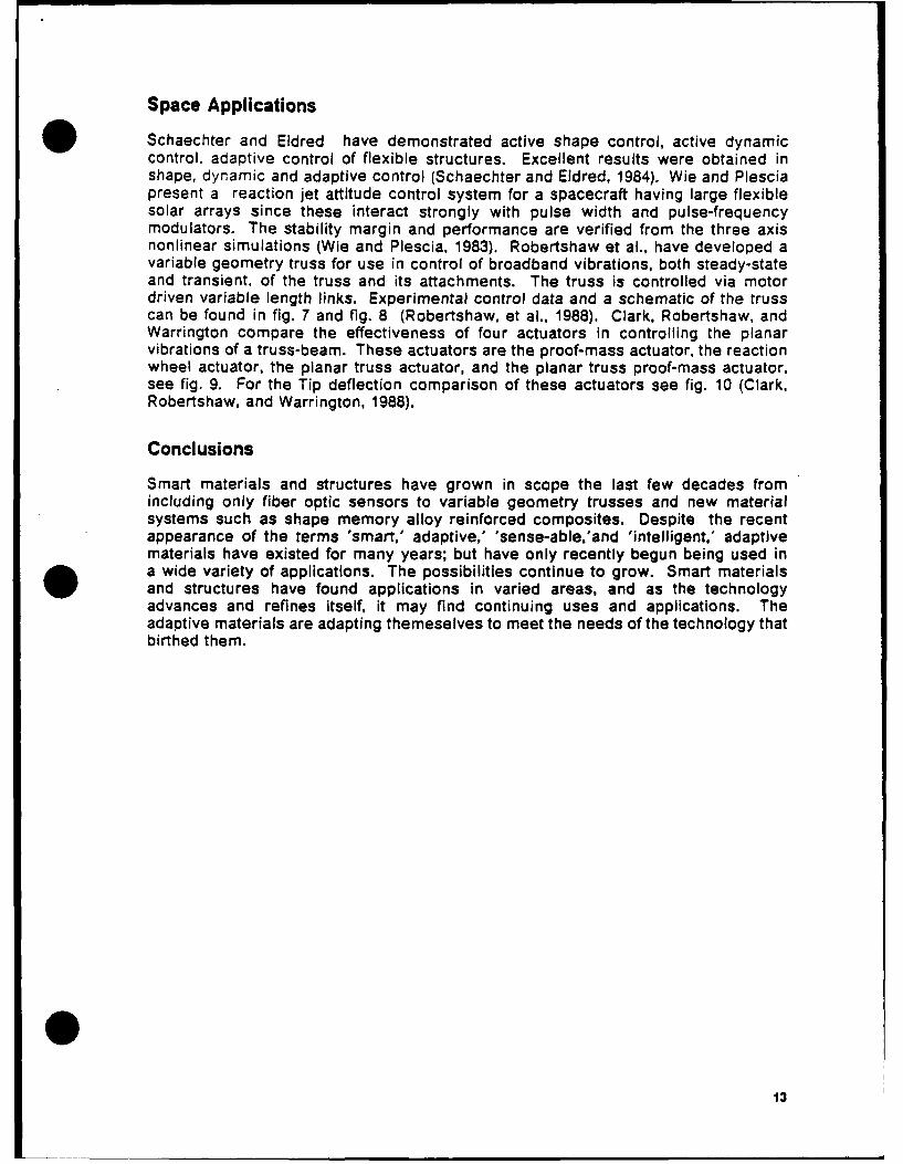
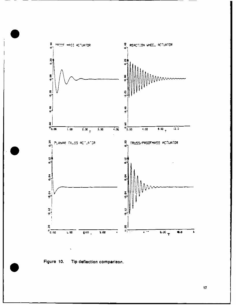
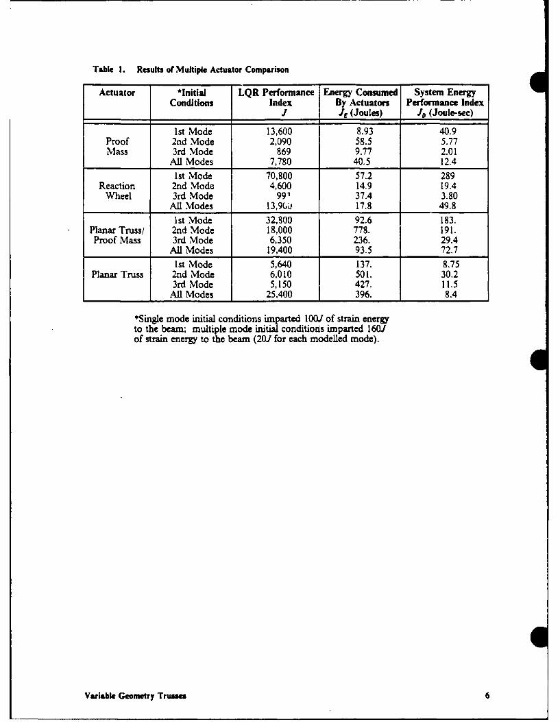
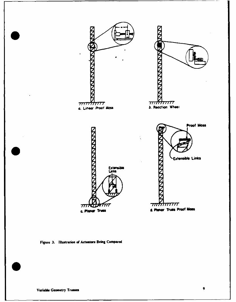
Schaechter and Eldred have demonstrated active shape control, active dynamiccontrol, adaptive control of flexible structures. Excellent results were obtained inshape, dynamic and adaptive control (Schaechter and Eldred, 1984). Wie and Plesciapresent a reaction jet attitude control system for a spacecraft having large flexiblesolar arrays since these interact strongly with pulse width and pulse-frequencymodulators. The stability margin and performance are verified from the three axisnonlinear simulations (Wie and Plescia, 1983). Robertshaw et al., have developed avariable geometry truss for use in control of broadband vibrations, both steady-stateand transient, of the truss and its attachments. The truss is controlled via motordriven variable length links. Experimental control data and a schematic of the trusscan be found in fig. 7 and fig. 8 (Robertshaw, et al., 1988). Clark, Robertshaw, andWarrington compare the effectiveness of four actuators in controlling the planarvibrations of a truss-beam. These actuators are the proof-mass actuator, the reactionwheel actuator, the planar truss actuator, and the planar truss proof-mass actuator,see fig. 9. For the Tip deflection comparison of these actuators see fig. 10 (Clark,Robertshaw, and Warrington, 1988).
Conclusions
Smart materials and structures have grown in scope the last few decades fromincluding only fiber optic sensors to variable geometry trusses and new materialsystems such as shape memory alloy reinforced composites. Despite the recentappearance of the terms 'smart,' adaptive,' 'sense-able/and 'intelligent,' adaptivematerials have existed for many years; but have only recently begun being used ina wide variety of applications. The possibilities continue to grow. Smart materialsand structures have found applications in varied areas, and as the technologyadvances and refines itself, it may find continuing uses and applications. Theadaptive materials are adapting themeselves to meet the needs of the technology thatbirthed them.
13
X 0-3
0.4I
-0.2
-0.4
a 0.
-0.4
-0.6
-0.
0 ..........
*Root strain Of Controlled First Mode (Experimental)
Figure 7. Strain vs. time for (a) Uncontrolled and (b) controlled 2 bay truss.
14
base plane
module I intermediate planeof variable links
top plane of thefirst module
module 2
vibrating rod
L-S I
'I
Figure 8. Active Spatial Truss Actuator Schematic.
015
a. Linear Proof Mass b. Reaction Wheel
Proof Mass
Extensible Links
ExtensibleLinks
c. Piaar Truss d. PIlaa Truss Proof Mass
Figure 9. Actuators
16
e0QTTF Id5 ACUATOR REACTION WHEEL AC7UATOR
o'1
0.0 1.0 Z.3 30.00 4.00 0.00 4.C 8.00 T 3
?L-ANAR T.-55 AC'P-3 TRUSS/PROOFMS ACTURTOR
o"i cg1 a
N N
e.c t.o 5 .O - -- S. ,
Figure 10. Tip deflection comparison.
17
References
Allan, R. "Nonvision sensors," Electronic Design. (27 June 1985) vol. 33, no. 15,p.103-15.
Avramovic, B., N. Barkakati, and G. L. Blankenship. "Application of a spectralfactorization approach to the control of flexible structures," Proceedings of the 23rdIEEE Conference on Decision and Control. Las Vegas, NV, vol. 3, (Dec 1984) p.1695-6.
Bailey, T., and J. E. Hubbard. "Distributed piezoelectric-polymer active vibrationcontrol of a cantilever beam," Journal of Guidance, Control, and Dynamics. vol. 8,no. 5, (Sept.-Oct., 1985) p. 605-11.
Balas, M. J. "Distributed parameter control of nonlinear flexible structures with linearfinite-dimensional controllers," Journal of Mathematical Analysis and Applications.vol. 108, (1985), p. 528-45.
Bar-Kana, I. and H. Kaufman. "Model reference adaptive control for time-variableinput commands, Proceedings of the 1982 Conference on Information Sciences, andSystems. Princeton, NJ, 1982, p.208-211.
Bar-Kana I. and H. Kaufman. "Some applications of direct adaptive control to largestructural systems," Journal of Guidance, Control, & Dynamics. vol. 7, no. 6,(Nov.-Dec., 1984) p.717-24.
Baumbick, R. J. "Fiber optics for propulsion control systems," Transactions of ASMEJournal of Engines,Gas Turbines and Power. vol. 107, no. 4, p.851-5 (Oct. 1985).
Bogue, R. "Developing Science of Accelerometers," Control and Instrumentation(GB). (Oct 1984) ,vol. 16, no. 10, p.69, 71.
Buchanan, H. J., R. W. Schock, and H. B. Waites. "An on-orbit experiment fordynamics and control of large structures," Journal of Guidance, Control, & Dynamics.vol. 7, no. 5, Sept-Oct, 1984. p.554-62.
Bucholtz, F., A.D. Kersey, A. Dandridge. "DC fibre optic acceleromter with sub-Agsensitivity," Electronic Letter (GB). vol 22, no.9, p. 451-3 (24 April 1986).
Burke, T. S., C. K. Taft. Proceedings of the 1984 American Control Conference, SanDiego, Calif. 6-8 June 1984, vol. 2. p.1026-31.
Cannon, R. H. Jr., and 0. E. Rosenthal. "Experiments in control of flexible structureswith noncollocated sensors and actuators," Journal of Guidance, Control, &Dynamics. vol. 7, no. 5, (Sept.-Oct., 1984) p. 546-53.
Choi, S. B., B. S. Thompson, and M. V. Gandhi. "Electro-rheological fluids technologystimulates a new generation of robotic and machine systems," Proceedings of theOklahoma State University's Applied Mechanisms Conference. vol. 1, 6-9 Dec, 1987.
Clark, W. W., H. H. Robertshaw, and T. J. Warrington. "A planar comparison ofactuators for vibration control of flexible structures," 1988.
Claus, R. 0., B. S. Jackson, R. G. May. "Nondestructive evaluation of composites byoptical time domain reflectometry in embedded optical fibers," ConferenceProceedings IEEE SOUTHEASTCON '85, Raleigh, NC, USA, 31 March - 3 April 1985(New York, USA IEEE 1985), p.241-5.
IS
Collier, M. J., S. M. McGlade P. E. Stephens. "The optical actuation of a processcontrol valve," Automation and Control (New Zealand). (June 1985) vol. 15, no.5, p.52-3, 56-7.
"Damping synthesis and damped design for flexible spacecraft and structures,"Computers and Structures vol. 20, no. 1-3, (1985), p. 563-74.
Goh, C. J. and T. K. Caughey. "On the stability problem caused by finite actuatordynamics in the collocat ed control of large space structures," International Journalof Control vol. 41, no. 3, (1985), p. 787-802.
Goh, C. J. and T. K. Caughey "A quasi-linear vibration suppression technique for largespace structures via stiffness modification," International Journal of Control vol. 41,no. 3, (1985), p. 803-12.
Greene. M. "Control of flexible bodies: new challenges in control engineering,"Proceedings of the Seventeenth Southeastern Symposium on System Theory.Auburn, Al., 24-26 March 1985 p. 89-92.
Hale, A. L. and R. J. Lisowski. "Reduced-order modeling applied to optimal designof maneuvering flexible structures," Proceedings of the 1985 American ControlConference. San Diego, CA, 6-8 June 1984, vol. 3, p.1685-90.
Hashimoto, et al. "Application of shape memory alloys to robotic actuators," Journalof Robotic Systems. tol. 2, no. 1, (Spring, 1985) p. 3-25.
Jones, B. E. Eletrotechnology (GB). (Oct. 1984) vol. 12, no.4, p.n148-5.
Joshi, S. M. "Robustness of velocity feedback controllers for flexible spacecraft,"IEEE Transactions of Aerospace and Electronics Systems. vol. AES-21, no. 1, (Jan1985), p. 2-7.
.juang, J. "Optimal Design of a passive vibration absorber for a truss beam," Journalof Guidance, Control, & Dynamics. vol. 7, no. 6, (Nov-Dec, 1984) p. 733-9.
Kissel, G. J., and D. R. Hegg. "Stability enhancement of flexible space structurecontrol," Proceeding of the 1985 American Control Conference. 19-21 June 1985, p.1194-202.
Main, R. P. "Fibre optic sensors - future light," Sensor Review, (GB). vol. 5, no. 3,(July 1985) p.133-9.
Mann, R. "So what future do you see in fibre optics ? " Process Engineering (GB) vol.66, no. 6, (June, 1985) p.79-81.
McClamroch, N. H. "Vibration control of flexible structures using member dampers,"Proceedings of the 24th Conference on Decision and Control. 11-13 Dec. 1985, Ft.Lauderdale, FL, vol. 2, p. 936 - 9.
Miller. D. F., V. B. Venkayya, and V. A. Tischler. "Integration of structures andcontrols - some computational issues," Proceedings of the 24th Conference onDecision and Control. Fort Lauderdale, Florida, (Dec 1985) p.924-31.
Miwa, Y. "Shape memory alloy application for sequential operation control," Systemand Control (Japan). vol. 29, no. 5, (May 1985). p. 303-10.
19
Morikawa, T. "Optical actuators." J. Soc. Instrumentation and Control Engineering(Japan). (Sept.1985) vol. 24, no.9, p.827-31.
Nakamura. Y., H. Hanafusa, N. Ueno. "A piezoelectric film sensor with uniformlyexpanded surface to detect tactile information for robotic end-effectors," Proceedingsof the '85 International Conference on Advanced Robotics. Tokyo, Japan, 9-10 Sept.1985, p.137-44.
Nurre, G. S. et al. "Dynamics and control of large space structures," Journal ofGuidance, Control, & Dynamics. vol. 7, no. 5, (Sept.-Oct., 1984) p.514-26.
Pennywitt, K. E. "Robotic Tactile Sensing," Byte. (Jan. 1986) vol.11, no.1, p.177-200.
Rajaram, S. and Junkins, J. L. "Identification of vibrating structures," Journal ofGuidance, Control, & Dynamics. vol. 8, no. 4, (July-August, 1985) p. 463-70.
Robertshaw, H. H. et al., "Dynamics and control of a spatial active truss actuator,"1988.
Rogers. C. A. and H. H. Robertshaw. "Investigation of processing techniques foradaptive materials utilizing shape memory alloys," 1988.
Ryaciotaki-Broussalis, H. A., and Broussalis, D. "Stable decentralized control offlexible space structures," Conference Record Eighteenth Asimolar Conference onCircuits, Systems and Computers. Pacific Grove California, 5-7 Nov. 1984, p.293-5.
Schaechter D. B. and Eldred, D. B. "Experimental Demonstration of the control offlexible structures," Journal of Guidance, Control, & Dynamics. vol.7, no. 5, (Sept-Oct,1984) p.527-34.
Silverberg, L. M. and L. Mierovitch. "Block-independent control of distributedstructures," Optimal Control Applications and Methods. vol. 6, (1985), p.281-9.
Sobel, K., H. Kaufman, and L. Mabius. "Implicit adaptive control for a class of MIMOsystems," IEEE Transactions on Aerospace and Electronic Systemsno. 5, Sept. 1982, p.576-90.
Su, S. F. 'Fiber-optic electric field sensors utilizing electro-absorption," ConferenceProceedings IEEE SOUTHEASTCON '85, Raleigh, NC, USA, 31 March - 3 April 1985(New York, USA IEEE 1985), p.241-5.
Sundararajan, N. and R. C. Montgomery. "Adaptive control of a flexible bean usingleast square lattice filters," IEEE Transactions on Aerospace and Electronic Systems.vol. AES-20, no.5, ,Sept 1984). p. 541-6.
Takahashi, S. "Piezoelectric ceramic actuator and it applications," Oyo Buturi(Japan). vol. 54, no. 6, p.587-8 (June 1985). In Japanese.
Tanoshima, K., T. Araki, and M. Tsukada. "Vibration analysis of piezoelectricactuators," IEEE 1984 Ultrasonics Symposium Proceedings. Dallas, Texas, 14-16 Nov.1984, vol. 2. p.882-7.
Tojo, T., K. and Sugihara. "Piezoelectricdriven turntable with high positioningaccuracy," Bulletin of the Japanese Society of Precision Engineers. vol.19, no.2,(June 1985). p.135-7.
Weeks, C. J. "Static shape determination and control for large space structures. 1.The flexible beam," Transactions of ASME, Journal of Dynamic SystemsMeasurement and Control. vol. 106 (Dec., 1984) p. 261-6.
20
Weeks, C. J. "Static shape determination and control for large space structures. II.A large space antenna," Transactions of ASME, Journal of Dynamic SystemsMeasurement and Control. vol. 106 (Dec., 1984) p. 266-72.
Wie, B. and C. T. Plescia. "Attitude stabilization of flexible spacecraft duringstationkeeping maneuvers," Journal of Guidance, Control, & Dynamics. vol.7, no.4,(July-August, 1984) p.430-6.
Yaeger, J. R. "A practical shape-memory electromechanical actuator," ISATA 84Proceedings, International Symposium on Automotive Technology and Automation.Milan, Italy, 24-28 Sept., 1984, vol. I. p. 633-42.
0
21
Session 1 - Smart Structures
C. A. Rogers, C. Liang, D. K. Barker, "Dynamic Control Concepts Using ShapeMemory Alloy Reinforced Plates", Virginia Polytechnic Institute and State Uni-versity.
R. 0. Claus, J. C. Mckeeman, R. G. May, and K. D. Bennett, "Optical FiberSensors and Signal Processing for Smart Materials and Structures Applica-tions", Virginia Polytechnic Institute and State University.
M. V. Gandhi, and B. S. Thompson, "A New Generation of RevolutionaryUltra-Advanced Intelligent Composite Materials Featuring Electro-RheologicalFluids", Michigan State University.
S. Hanagud, M. W. Obal, and A. G. Calise, "Piezoceramic Devices and PVDFFilms as Sensors and Actuators for Intelligent Structures", Georgia Institute ofTechnology.
H. H. Robertshaw, and C. F. Reinholtz, "Variable Geometry Trusses", VirginiaPolytechnic Institute and State University.
E. I. Rivin, "Passive Self-Adaptive Structures", Abstract, Wayne State Univer-sity
T. G. Duclos, J. P. Coulter, and L. R. Miller, "Applications for Smart Materialsin the Field of Vibration Control", Thomas Lord Research Center.
*0
DYNAMIC CONTROL CONCEPTS USINGSHAPE MEMORY ALLOY REINFORCED PLATES
C. A. RogersC. Liang
D. K. Barker
Smart Materials & Structures LaboratoryMechanical Engineering Department
Virginia Polytechnic Institute & State UniversityBlacksburg, Virginia 24061
ABSTRACT
'Active modal modification' and 'active strain energy tuning' are concepts that haveonly recently become a possibility with the recent development of shape memory al-loy (SMA) reinforced composites. Shape memory alloy reinforced composites is aclass of materials that have the ability to; change thier material properties, inducelarge internal forces in the materials, modify the stress and strain state of the struc-ture, and alter its configuration, all in a controlled fashion. Active modal modificationuses the shape memory alloy's capability of changing its stiffness during a temper-ature activated, reversible, phase transformation thereby modifying the modal re-sponse of the structure. Active strain energy tuning adds to the active modalmodification concept the ability to use the shape memory alloys ability to impart largedistributed loads throughout the material to alter the stored strain energy within thecomposite structure and therby modify the modal response of the structure.
This paper will present simulations of the modal response of square, quasi-isotropic,SMA reinforced composite plates demonstrating several new concepts and applica-tions for active control of composite structures. Naturally, when the Young's modulusof SMA 'fibers' is increased or large forces are distributed throughout the structureduring the reversible phase transformation, not only is the modal response varied,such as the natural frequency and mode shapes, but the maximum deflection and itslocation on the plate is also changed. Both static deflection (stiffness) and modalresponse simulations will be presented.
INTRODUCTION
Shape memory alloy reinforced composites are an extremely versatile class of ma-terials recently developed at VPI&SU. Using shape memory alloys as fiber re-inforcement gives structures numerous adaptive capabilities. Adaptive and 'Smart'materials, which contain distributed actuators, sensors, and microprocessor capabil-ities, can be used in many applications requiring a high degree of adaptability tochanging external and internal conditions. External conditions may consist of envi-ronment, loads, or the desire to change the scope, purpose, or geometry of thestructure after it has been built and is in service. Internal conditions may be damageor failure to isolated portions of the material or structure.
The number of applications requiring or desiring such adaptability is increasing rap-idly and more are sure to follow as the technology is more readily transfered to theproduction level. One of the current needs is for long-duration unattended materialsand structures that can be used in isolated environments (i.e., submarines, Naval
vessels, defense vehicles, and the space station) or in biomedical applications. Us-ing adaptive/intelligent materials may result in structures with self-inspection andself-identification capabilities which can direct the adaptive response based on theenvironment and/or damage to the structure.
The ability to adaptively alter the mission, scope, objectives, and geometry of astructure will have tremendous impact on the design philosophy of structures in thefuture. For example, a structural member made of Shape Memory Alloy (SMA) rein-forced composites can compensate for deterioration in absorptivity and thermal ex-pansion properties that result in excessive change in length of that or other membersas well as control the motion and vibration of the structure. The same material canbe used to change load paths in a structure or within the material so that the com-ponent can be replaced or repaired before it causes catastrophic failure of the systemor unacceptable degradation of performance.
Applications for adaptive/intelligent materials include:
* Failure detection/prevention of structures (i.e., bridges, walkways, phone andelectrical cables, and mechanical components).
• Active vibration control and structural acoustic suppression for acoustic enclo-sures, propeller aircraft, large flexible structures, etc.
" Active vibration control of helicopter rotor blades." Thermal expansion balancing.• Robot manipulators (fingers).* Thermally activated valves and ducts.• Thermal switches.* Structural dimension adjustment and environment adaptation for large reflector
antennas.
The development and subsequent production of this class of materials could havetremendous impact on several diverse technological fields, i.e., material science, vi-brations and controls, ocean and aerospace structures, biotechnology, and may actas a catalyst for the development of many new devices and technologies. Brief de-scriptions of some the applications and the corresponding basic operational modesof the shape memory alloy reinforced composites appear in Ref. (1].
Introduction to Shape Memory Alloys
In 1965, Buehler and Wiley of the U.S. Naval Ordnance Laboratory received a UnitedStates Patent on a series of engineering alloys that possess a unique mechanical(shape) "memory" (2]. The generic name of the series of alloys is 55-Nitinol. Thesealloys have chemical compositions in the range of 53 to 57 weight percent nickel. Agreat deal of effort was expended over the next ten years in characterizing the ma-terial and developing new applications to exploit its remarkable shape memory effect(SME) and its unusual mechanical properties. The Naval Ordnance Laboratory (nowknown as the Naval Surface Weapons Center) was and still Is the leader in charac-terizing Nitinol. Several other laboratories have made significant contributions to theunderstanding of the Nitinol, in particular is Battelle Memorial Institute and NASA.
The shape-memory effect (SME) can be described very basically as follows: an objectin the low-temperature martensitic condition, when plastically deformed and the ex-ternal stresses removed will regain its original (memory) shape when heated. Theprocess, or phenomenon, is the result of a martensitic transformation taking placeduring heating. Although the exact mechanism by which the shape recovery takesplace is a subject of controversy, a great deal has been learned about the uniqueproperties of this class of materials in the past twenty years (10-12]. It appears clear
however that the process of regaining the original shape is associated with a reversetransformation of the deformed martensitic phase to the higher temperature austenitephase.
Many materials are known to exhibit the shape memory effect. They include thecopper alloy systems of Cu-Zn, Cu-Zn-Al, Cu-Zn-Ga, Cu-Zn-Sn, Cu-Zn-Si, Cu-Al-Ni,Cu-Au-Zn, Cu-Sn, and the alloys of Au-Cd, Ni-Al, Fe-Pt, and others. The most commonof the shape memory alloys or transformation metals is a nickel-titanium alloy knownas Nitinol.
Nickel-titanium alloys (Nitinol, NiTi) of proper composition exhibit unique mechanicalmemory" or restoration force characteristics. The name is derived I )m Ni (Nickel)
- Ti (Titanium) - NOL (Naval Ordinance Laboratory). The shape recovery performanceof Nitinol is phenomenal. The material can be plastically deformed in its low-temperature martensite phase and then restored to the original configuration orshape by heating it above the characteristic transition temperature. This unusualbehavior is limited to NiTi alloys having near-equiatomic composition. Plastic strainsof typically six-to-eight percent may be completely recovered by heating the materialso as to transform it to its austenite phase. Restraining the material from regainingits memory shape can yield stresses of 100,000 psi (the yield strength of martensiticNitinol is approximately 12,000 psi).
For some applications, creating large internal forces within the material or structureare not needed or desireable. Shape memory alloys have the unique ability ofchanging its material properties, reversiblly, and this characteristic can be exploitedwithout embedding plastically deformed SMA 'fibers' nor creating large forces anddeformations of the structure. This capability is exploited in the concept that will befurther explained below, termed "Active Modal Modification'.
Substantial progress has been made in understanding the nature of the "shapememory effect" (SME). A great deal of literature has been published over the pasttwenty years presenting detailed thermal, electrical, magnetic, and mechanical char-acterizations of this unusual alloy [3-10]. However, there is still much to be learnedabout the influence of residual stress and high temperatures, that may be used incomposite fabrication and processing, on the extent, duration and repeatability onSME as well as the dynamic actuator and sensing characteristics of Nitinol.
Shape Memory Alloy Reinforced Composites
The class of the material referred to as SMA reinforced composites in this paper issimply a composite material that contains shape memory alloy fibers (or films) insuch a way that the material can be stiffened or controlled by the addition of heat (i.e.,apply a current through the fibers) (1,2]. Shape memory alloys and the mechanismby which they exhibit the characteristic shape memory effect (SME) is explained verybriefly below and in greater detail in references [3-9]. One of the many possibleconfigurations of the SMA reinforced composite material is one in which the shapememory alloy fibers are embedded in a material off of the neutral axis on both sidesof the beam in agonist-antagonist pairs. Before embedding the fibers, the shapememory alloy fibers are plastically elongated and constrained from contracting totheir 'normal' or 'memorized' length upon curing the composite material with high-temperature. The plastically deformed fibers are therefore an integral part of thecomposite material and the structure. When the fibers are heated, generally bypassing a current through the shape memory alloy, the fibers 'try' to contract to their'normal' or 'memorized' length and therefore generate a uniformly distributed shearload along the entire length of the fibers. The shear load offset from the neutral axis
of the structure will then cause the structure to bend in a known and predictablemanner.
There are numerous other configurations, such as creating 'sleeves' within the com-posite laminate which the plastically elongated shape-memory alloy can be insertedand then clamped to both ends. When the shape memory alloy is heated, the fiberstry to contract in the same fashion as explained above. When one end of the beamis free, the fibers in a sleeve will exert a concentrated force on the ends of thestructure in a direction that is always tangent to the structure at the point where thefibers are clamped to the structure. When both ends of the beam are fixed, heatingthe SMA results in 'fibers' with a siginificantly increased stiffness and applied tensionthat will resist any transverse motion. The difference between the embedded fibersand the fibers in a sleeve is that in the first case the force of the shape memory alloyis distributed over the length of the fiber and in the later case the force is concen-trated at the end of the structure.
Shape Memory Alloy (SMA) reinforced composites have tremendous potential forcreating new paradigms for material-structures interaction (11]. The list of scientificareas that can be influenlced by novel approaches possible with SMA reinforcedcomposites is quite large. For example, vibration control can be accomplished byusing the distributed force actuator capabilities similar to the common piezoelectricsystems. However, two unique approaches to active control are possible with a ma-terial that can change its stiffness, physical properties and in the second case, applylarge distributed loads throughout the structure: i) Active Strain Energy Tuning, andii) Active Modal Modification. Simulation results showing the potential for SMA rein-forced composites to vary the modal response of a composite plate will be presentedbelow.
Transient and steady-state vibration control can be accomplished with SMA rein-forced composites using several techniques. Transient vibration control is definedhere as the ability to suppress or damp structural vibration by applying forces (dis-tributed and/or point) to the structure in such a way as to dissipate the energy withinthe structure. This is accomplished generally by applying point transverse loads tothe structure or applying an 'actuator film' to the surface of the structure. The ap-proach with SMA reinforced composites is to simply embed the actuators (shapememory alloys) in the structure such that, when actuated correctly, they exertagonist-antagonist forces off the neutral axis thereby reducing vibrations (1]. Steadystate vibration control is the ability to change the modal characteristics of the struc-ture. The mechanism in SMA reinforced composites is to increase the stiffness of thecomposite in different directions by predetermined amounts through the SMAactuators.
Applications for SMA reinforced composites extend far beyoi,d vibration controltasks. Active buckling control, or more generically active structural modificationschemes, can be imagined in which SMA fibers are stiffened within a composite toalter the critical buckling load of the structure. SMA composites that are used forvarious vibration control tasks would also be used for motion or shape control, al-lowing a structure to maintain a given shape or orientation for an extended period oftime. The physical, thermal, and controller design will be much more critical than inthe transient vibration control scenario. Motion and shape control will in all likelihoodinvolve the simultaneous use of force actuators (SMA) and stiffness actuators (thetechnique in which the SMA is heated to change its modulus of elasticity) to createa structure that behaves much like a mechanical muscle. Another possible designapproach is to actuate single fibers with pulse-type signals, much like the all-or-nothing actuation of the individual muscle fibers in the human muscle.
Active Control Concepts
0 Steady-state vibration control which may also be used for structural acoustic controlcan be accomplished with SMA reinforced composites using a novel techniquetermed "Active Modal Modification' (121. The modal response of a structure or me-chanical component (i.e., plate or beam) can be tuned or modified by simply heatingthe SMA fibers or lamina to change the stiffness of all or portions of the structure.When Nitinol is heated to cause the material transformation from the martensiticphase to the austenite phase, the Young's modulus changes by a factor of approxi-mately four as shown in Fig 1. Not only is the stiffness increased by a factor of fourbut the yield strength also increases by a factor of ten. This change in the materialproperties occur because of a phase transformation and does not result in any ap-preciable force and does not need to be initiated by any plastic deformation.
In 'Active Strain Energy Tuning' the shape memory alloy fibers are placed in or on thestructure in such a way that when activated there is no resulting deflections but in-stead the structure is placed in a 'residual' state of strain. The resulting stored strainenergy (tension or compression) changes the energy balance of the structure andmodifies the modal response much like tuning a guitar string.
Active strain energy tuning utilizes both the embedded fiber and sleeve method de-scribed earlier. The difference between the epoxied fibers and the fibers in a sleeveis that in the first case the force of the shape memory alloy is distributed over thelength of the fiber and in the latter case the force is concentrated at the end of thestructure or is used to resist transverse motion. Both of the design concepts de-scribed above have been incorporated into prototypes and their potential demon-strated on a limited scale. The simulations presented below assume embedded
* fibers unless otherwise specified.
FORMULATION
Simulations of active strain energy tuning by tuning the material properties of de-formed SMA fibers and imparting distributed loads along the length of the fibers of a'SMA-Epoxy' quasi-isotropic square plate will be presented by evaluating the free vi-bration response and also the variation of the square plate's variation of bendingstiffness. Investigating the effect of active strain energy tuning on a quasi-isotropicplate constrains the following formulation and discussion to midplane symmetriclaminates (B,, = 0) with the distributed 'fiber' loads assumed to be 'inplane loads'.Therefor, the simulation for active strain energy tuning and active modal modificationuse similar developments with the only difference being the inclusion of inplaneloads for ASET.
Bending of Simply-Supported Plates
The geometry used for all of the simulations and discussion presented in this paperis shown in Fig. 2. Neglecting inertia terms, for static bending analysis, the govern-ing differential equation of motion is
The boundary conditions for simply-supported edges are
x 13- 130
II 110
9- 90 40M0304NT IEL02PERCENT YIELD
~7 -Rj70-
:31 10 MoouwMt MdI
13- 130 1
0z110- CMOAU
00Q2 PERCENT YILSD~7~70 STRESS
(nj
C - 30
a 2T1NN IEDATING
5: -100 -20 60 140 220 300
TEMPERATUFPE, OF
Figure 1. Yield Stress and Elastic Modulus vs. Temperature
z z
Figure 2. Restoring Stress vs. Temperature for Nitinol
2W a2 2atQx = 0anda: w M x =-x DI, --- 2D,, -,w--D
2 2 c2w = 0 [2]
at y = 0 and b: w=My-D12 - 2 D 26f - D 22 2 [3
Using the Ritz method to obtain an approximate solution to the governing equationyields the energy expressionfo,,,12 ,21W- (922 22 2 ]4
0 axO, -L-= +2, a y or 2 ay 4:
[4(OS aw+ D2eA-2w) 02W + 4Os( a2W)2
+ [TI7 N-L + 2 Nx ox<dd[( _L + (w )2+ 2j y w- 2w - qw] I x dx la- ',y 'Ox ay
= stationary value
The assumed solution for the energy expression, Eq. 4, using the separation of vari-ables is
M N
W = FZ FZAmnXml(X)ynY [5]mnMI
Substituting this series into the energy expression, Eq. 4, the following set ofequations result.
dZo~ d2X, d 2Xm
[f s: dd2 a d d2r d2X, vi,--dy+n 1
D L[- 4 dxf Y, Y dy+'X- 2 m dXV Jn+,. 1 ,, <,dx o 0,,+ fo , dx I, ,
[i.:,. ,d2 Y d 2y, dX, dXm ,b, dy dY, 1+ D221 XgXmdx - d dy+ 4De - dxj I dy I
[.1 fo0 dy 2 dy 2.Jodx dx .0 d1) dy j
rra d2X, dXm tb dY fb dYj ]+w16[J . +xf Y-, -5- dy[ : dIx, 2, x dx,,,' d X dxf , dy[O f[ d}
a22~ m dXj bdY, d 2 Y, J dXm bd2 Yj dY,
+ o 'x,,d dX, _ d w d # ,, , d x, - +,x ddy2D I"XM dx N VX...... 2+N d , d dy
+ o -dx x y~mXdy dy I dx dy dy dy
"qoj Xmdxf Yndy m-1,2,... Mn-1,2 . N
The MxN linear simultaneous equations are then rewritten in matrix form as
['K'lAmn) -= [qn [71]
Using the Ritz method to solve the energy equation allows for the assumed solutionto only satisfy the displacement boundary conditions (a solution in a variables sepa-rable form which satisfies the moment equations does not exist). For a simply-supported plate, the double sine series in conjunction with the assumed solutiongiven by Eq. 5 is sufficient.
Xm(x) = sin D"" [8]
Yn(y) sin lryb
At this point, the unknown coefficients, A,,,,,, are determined and the deflections cal-culated using the assumed solution of Eq. 5. Because of the approximate nature ofthe Ritz method, care must be taken to insure convergence of the solution and thatthe coupling terms, D,, and D. , are accounted for appropriately (see ref. [13]).
Free Vibration of Simply-Supported Plates
The formulation of free vibration response of rectangular anisotropic plates is verysimilar to that described above for the bending problem. The primary difference inthe two solutions is that inertia terms must be added to the governing equation forfree vibration analysis and the external load, q(x,y), used in the bending formulationmay now be neglected. However, the same basic approach must be followed,namely, the Ritz solution method is followed which involves as before, writing theenergy equation governing free vibration (assuming no lateral loads).
f . D:[D11 x )2 + 2D,2 ax 2 2 022 Q7)] (9)f... I >1 y '
D16 k TfW +D2 2- ew +4D _
a26 dy2 ) axay a x49y
+ [W( I )2+ Y IW 2+2 _2t_2tP2W2]]d.XdY
- stationary value
The natural modal response of the plate is found by using the same assumed solutionas given above, Eq. 4, and by substituting the same double sine series into the re-sulting MxN homogeneous simultaneous equations
&4~ d 2X, d 2X bD,, dx YY.dy DO]
,,Lf dX 2 dx 2 O
+ °"2[Jox ,fx-,X, ,- + fx x,-; 2 Xnd d2- 1]LO dx2 d 0da y2
d 2 d,, 2dx, dX 'b d 2,,+ D12 -M '^- dx Y- dy + 0 i dx Y" -- dyIdy dy dx dx d 0 dy dy
MY0[ d 2 dY C0 dv, C 0 dy 1[ o dy 2 ,xsdy,2.. o x,,., dyd+2OI[ x tx-- dx Y"dy + ' YV dy
1[odx 2 dx dy f 0o J
dX d-j d-- d- IX,- dx' dyI+ 2026 Xmdx dy dy I dY2 dy
+ fxfK , dd,_ dy dY. 2.,y + 1y dxdy
0 Nx, dX dx yrldy dy XYmdx dy dx dy
-- XXmdx g dy = 0 m 1, J2=...,. M
0 0n 1,2,.... N
Since the MxN simultaneous equations are homogeneous, a nontrivial solution canbe obtained only if the determinant of the coefficient matrix, [K], is zero. Therefor, theeigenvalues of [K] are determined which then reflect the natural frequencies of freevibration.
The formulation must be further expanded for SMA reinforced composites as thebending stiffnesses (0,,) are functions of temperature and can be tuned by activatingindividual plys of a laminate resulting in a change of the fiber modulus (see Fig. 1)by as much as a factor of four. The change in the fiber modulus occurs over a rela-tively small temperature range (selectable from 10 to 200C) and is a result of a solidphase material transformation between the martensite and austenite phases. There-fore, the superscripts 'M' and 'A' are used to denote the physical and mechanicalproperties in each phase. Unsuperscripted values are intended to represent instan-taneous values which are 'tunable' between the martensitic and austenitic (extreme)values.
. Determination of Inplane 'Fiber' Loads
One of the basic assumptions or conditions used in the analysis described herein isthat the laminate remain midplane symmetric at all times. This means that corre-sponding lamina with the same fiber orientation (on both sides of the midplane) areactivated simultaneously. This assumption then allows for the induced distributedloads to be modeled as general inplane loads as they cause no transverse displace-ments or moments.
The first numerical procedure that must be performed is to determine the resultinginplane load that can be applied to the plate's boundary to model the distributed 'fi-ber' loads. The method involves first considering a small element containing theappropriate fraction of fiber and matrix. Recall that prior to embedding the SMA fiberin the matrix, the SMA fiber is strained plastically an amount t,. The initial strain inthe fiber can then be used to generate large restoring stresses, a,, in the compositewhen the fiber is 'activated'. Fig. 3 shows a typical maximum restoring stress vs.initial strain for Nitinol. Therefore, upon activating the SMA fibers in a particularlamina the fibers exert a large stress distributed throughout the laminate resulting ina reduced strain of the fiber and an increased strain in the laminate, C (assuming theboundary is free). The stress needed to recover the compressive strain, C, of thelaminate is the equivalent inplane load that is to applied to the laminate boundaries.For example, if t, - 2.0% then from Fig. 3 the restoring stress is 24 kpsi. However, the24 kpsi will compress the matrix material in some sense (assuming free boundaryconditions) and internal equilibrium will be satisfied by letting the fiber and matrixstresses being equal, a, - e,. Now assuming that the fiber and matrix have the same
* deformation in the fiber direction the laminate strain is determined:
Or = E11]
80 -,
70"
so.:
40
1301
20-
10
0.0 0.2 0.4 0.6 0.8
NTmN w
Figure 3. Maximum Restoring Stress vs. Initial Strain
2.0. Ac:vac io of Tadivdua. Plys 2.0 Activation of EntieT L±-rate
Figure 4. Flexural Stiffness Tuning of Quasi-Isotropic Plate
assuming E, = 4mpsi and o, = 24kps! results in the laminate strain, c, being 0.6 %.The 0.6 percent strain then reduces the SMA fiber strain to 1.4% from the free con-traction of the laminate and therefore the corresponding restoring stress is decreasednonlinearly as shown in Fig. 3. Continuing the numerical example above; for 1.4%SMA fiber strain the a, is 20 kpsi resulting in the total laminate strain being 0.5%.This iterative procedure is then continued to convergence and may be described btthe expressions below.
r fn = a~n) = E[ n) [12]
Upon convergence, the resulting z is then used to determine the necessary inplaneloads, N,N,. and N,.
RESULTS
Problem Definition
The simulation results have been generated based upon several assumptions. First,the laminates are all quasi-isotropic, [ +45, - 45*,00,900], , in the unactivated stateand always remain midplane symmetric which means that the lamina pairs above andbelow the midplane. with the same fiber orientation are activated simultaneously.Secondly, all of the plates are square (even though the formulation allows for generalrectangular plates) with simply-supported boundaries.
The material used in all simulations is Nitinol/Epoxy with a fiber volume fraction of50% unless otherwise noted. The macroscopic lamina properties are determinedfrom the rule-of-mixtures. Several simplifying assumptions were adopted relating tothe restoring stress of Nitinol and the variation of the fiber's elastic modulus uponactivation. The initial restoring stress, a, , of the SMA fibers as a function of fiberstrain was determined from Fig. 3, however in simulations in which the fibers arepartially activated the restoring stress is varied linearly from zero to its maximumstress and the Young's modulus is also varied linearly from 4 mpsi to 16 mpsi. Futurework will generalize the nonlinear functions of restoring stress and elastic moduluswith temperature as well as consider thermal effects.
ACTIVE MODAL MODIFICATION (AMM)
Variation of Plate Stiffness and Maximum Deflections
The stiffness of a composite plate, extension or bending, can be taylored within rea-sonable bounds. However, SMA reinforced composites can be taylored to not onlyhave a specified stiffness but can be taylored to have a range of material propertiesthat can be controlled or tuned. For example, Fig. 4 shows the change in the flexuralstiffness (0,,) of the square plate when one or all of the individual lamina are activatedsuch that the fiber modulus increases. Simply activating the top and bottom +450ply can modify the plate flexural stiffness by over 40 percent. Activating all of the plysto increase the fiber modulus by a factor of four increases the flexural stiffness byapproximately 90 percent. By utilizing the numerous permutations of activatedlaminae to unactivated laminae and using modulation schemes in which some laminacan be only partially activated can result in subtle and versatile control possibilities.Changing the stiffness of a composite structure has some important practical impli-cations. One prime example is in active structural acoustic control where the radi-
ated sound pressure levels can be reduced dramatically by reducing the amplitudeof the structural acoustic vibrations. Obviously changing the stiffness of the platealso changes its dynamic response and has other significant implications on vibrationand acoustic control which will be described below.
Variation of Natural Frequencies and Mode Shapes
Naturally, changing the stiffness of a structure impacts on more than the maximumdeflection but also modifies the modal response of the structure, hence the term'Active Modal Modification'. One of the objectives of Active Modal Modification is totune the structure based upon various performance criteria or external conditionssuch as periodic force or pressure inputs to the structure that may be near resonantfrequencies or result in low transmission loss. Active or adaptive control of thestiffness of the structure will influence the nature of the modal response of thestructure by changing the natural frequencies and the characteristic mode shapes.Utilizing classical composite technology in which structures are fabricated withtaylored properties and various orientations of individual plys allow for tremendousflexibility in the structural design of these tunable structures for various applications.
Figure 5 illustrates the potential for changing the natural frequency of a squarequasi-isotropic plate by activating one or all of the individual plys. Again, the greatestauthority is achieved, for single lamina activation, by activating the +45* plys that arepositioned on the top and bottom surfaces of the plate. However, by activating vari-ous permutations of lamina the control of the natural frequencies and stiffnesses canbe accomplished in a more sophisticated manner perhaps allowing for dual-requirements associated with the orthotropy of the structure and the modal responsein a coupled fashion.
The authority of SMA reinforced composites is quite dramatic for active modal mod-ification. Activating the +450 plys result in approximately a 25 percent increase inthe natural frequencies and activating all of the plys increase the natural frequenciesby about 50 percent. The impact of tuning the stiffness of the fibers is also seen inthe modification of the mode shapes which naturally occur because of the increasedorthotropy introduced by changing the stiffness of a ply or plys of an initially quasi-isotropic structure. Again, the concept of tuning the mode shapes of a structure isanother novel approach to composite design.
Modification of the mode shapes associated with the fourth natural frequency areshown in Figs. 6 and 7. Figure 6 shows the mode shape for the quasi-isotropic squareplate without any activated fibers or plys. Note that quasi-isotropic plate does nothave an anti-node line In the center of the plate as it is only quasi-isotropic in exten-sion and is but only a close approximation to isotropic in bending. When the +450plys are activated in the plate, the flexural stiffness increases, the natural frequencyincreases and the characteristic mode shapes also change as illustrated in Fig. 6.Comparing Figs. 6 and 7 show the dramatic change in the location of the nodes andanti-node lines which also indicate the possiblity of tuning the impedance and mo-bility of any point on the plate. Lastly, Fig. 8 shows some of the variations in modeshapes and natural frequencies that can be accomplished by activating individualplys of the entire structure.
Activati±n of Individual Plys Activacion of. Entire Lamnate•110 140
Figure 5. Natural Frequency Tuning of Quasi-Isotropic Plate
z
* , ' , * "
* J . ,
..........s. ... -----.
.. _ ..-.- ' -- ,-4.5.
TI
Figure 6. Mode Shape of Unactivated [+45, - 45,0,90), Plate
zr
9I I - 4 '
I f
I / ] 9 I ". • I I . Q El
0..5 60. -- 6.
3 . ..de D . E - % ... E l-- -
... "
-k. 0. 629 5. 0. 21.
Figure 7. Mode Shape of d+45, - 45,0,90 , Plate with Activated + 450 Plys
la e 4.45 -1. 40 40
* iS., z1 .z z5z.a 20.0 20.4 28.t
k - 4 9f5 40.1 6|.3 .W ' *~ ;i
I k - 1.6 42.9t 34.1 30.0 53.2 70.1.
* 79.5 1030 91.2 79. 1 j.J
Figure 8. Comparison of Mode Shapes for ("+45, - 45,0,90J, SMA Reinforced
Plate
ACTIVE STRAIN ENERGY TUNING (ASET)
Variation of Plate Stiffness and Maximum Deflections
One of the unique capabilities of SMA reinforced composite materials is that struc-tures (or components) can be designed with a specific range of material propertiesthat can be controlled or tuned over a relatively large range. For example, Fig. 4shows the change in the flexural stiffness (D,) of the square plate when one or all ofthe individual lamina are activated by active modal modification (12], i.e., the fibermodulus is increased by a factor of four. However, active strain energy tuning allowsfor even greater authority. Figure 9 illustrates the increased authority over maximumdisplacements for a uniformly loaded plate by comparing active modal modificationand active strain energy tuning. Recall that active strain energy tuning incorporatesthe response of active modal modification as the Young's modulus of Nitinol is as-sumed to increase linearly with restoring stress and the percent activation. The re-sults shown in Fig. 9 also assumes an initial strain of the SMA 'fibers' of only 2%even though Nitinol can regain 8% plastic strain and the maximum restoring stressis also realized at 8% strain.
The authority of active strain energy tuning is obvious for SMA/Epoxy composites andeven greater authority may be possible if larger initial strains could be used in theembedded fibers. The limiting initial strain of the fibers is dependent on severalphysical considerations, including; the choice of resin system, the reliability and du-rability of bond between the fibers and matrix, the maximum, average, and distrib-ution of stresses throughout the matrix material. However, it is somewhat clear that50% fiber volume fraction is not necessary and in many situations is not desireable.Because of the effect of the inplane distributed loads, the fiber volume fraction canbe reduced without significantly increasing the maximum deflection relative to activemodal modification. Figure 10 shows the effect of the flexural stiffness, D,,, as afunction of fiber volume fraction. Similarly, Fig. 9 shows the maximum plate dis-placement normalized with respect to the maximum plate displacement for activemodal modification with a 50% fiber volume fraction.
Variation of Natural Frequencies and Mode Shapes
Active strain energy tuning can be applied to a structure to influence numerousstructural interactions such as deflections, buckling, and of course, natural frequen-cies and mode shapes. As was explained in Ref. [12], the primary objective of activemodal modification and active strain energy tuning is to 'tune' the structure basedupon various performance criteria or external conditions such as periodic force orpressure inputs to the structure that may be near resonant frequencies or result inlow transmission loss. Active strain energy tuning again allows for greater authorityand versatility of control to be excersized over active modal modification to vary thenatural frequencies and to alter the modal shapes of the structure.
Simulations of the first ten mode shapes of the quasi-isotropic plate for a totally un-activated plate, activation of only the 450 and 900 plys, and when all the layers areactivated, are shown in Fig. 11. Naturally the mode shapes for the unactivated andtotally activated plate are identical, however, the natural frequencies for the totallyactivated plate are from five to ten times higher for the totally activated case. Table1 shows the range of control of the natural frequencies that is possible with aNitinol/Epoxy composite with a 50% fiber volume fraction. Even though the range offrequencies is quite broad, it is also somewhat clear that for most adaptive controlschemes that less dramatic variations will suffice and perhaps simplify fabrication,processing, reliability, and durability of such a structure. Figure 12 shows the effect
0. 0050
0. 0045 -
0.0040 ----------
S0. 0035 -0 Active Strain Energy Tuning
m0.0030
S0.0025-
0.0020
0.00151
0.0010
0.00051 Active Modal Modification
0.00000 25 50 75 100
ACIVATION EIINTAGE
Figure 9. Maximum Plate Deflection Under a Uniform Pressure Load Using Ac-tive SMA Control
130'
110 1I90~
70
850
30
10 . ........ ,........ - . . . . . . . .
0.1 0.2 0.3 0.4 0.5
RATIO
Figure 10. Flexural Stiffness Tuning of Quasi-Isotropic Plates Using ActiveStrain Energy Tuning
First Ten Mode Shape of a Quasi-Isotropic Plate
All Activated 90°Activated 45*Activated
Unactiva ted
1 6 L 6 L 6
27 2 7 2 7
3 8 3 8 *. 3 a
4 9 9 4 9
5 10 S to $ L0
Figure 11. Comparison of Mode Shapes of Quasi-Isotropic Plates Using ActiveStrain Energy Tuning
Table 1. Natural Frequency of 1 +450, -45*, 08, 900], Plate Using Active Strain EnergyTuning
Mode Unactivated Activated PlysPlate +45* -45° 0° 90 All
1 20 ill 119 113 124 225
2 49 179 192 120 132 358
3 50 180 193 143 157 358
4 80 233 249 190 208 456
5 99 263 281 227 250 511
6 99 264 281 234 258 512
7 129 305 326 252 277 587
8 129 312 330 260 285 588
9 167 360 382 287 315 674
10 168 360 382 345 378 676
of fiber volume fraction on the variation of the first four natural frequencies when alllayers of the plate are activated (recall that the second and third mode of a quasi-isotropic plate are essentially degenerative, hence only three lines for the four modesin Fig. 12). The first mode for 0.1% fiber volume fraction is approximately four timesgreater than the unactivated plate. The fourth natural frequency is more than a factorof two greater than unactivated plate. Figure 12 indicates that embedding relativelysmall amounts of SMA fibers in conventional composites, (i.e., graphite/epoxy orglass/epoxy), could prove to produce significant variations of the natural frequencies.
EXPERIMENT
Experimental Procedure and Apparatus
A nitinol reinforced fiber-glass beam was fabricated at the Composite Materials andStructures Fabrication Center at VPI&SU. The beam was made of mainly 90 degreeplys to minimize the natural frequency of the beam. Thin strips of zero degree plyswere appropriately placed in the lay-up to create open channels along the neutralaxis of the beam. Teflon fibers, the same size as the nitinol wire, were placed in thechannels during the lay-up proceedure so that the epoxy in the fiber-glass would flowaround the teflon fibers during the cure cycle to create circular sleeves along theentire length of the beam. After the cure cycle, the teflon fibers were removed fromthe beam and plastically elongated nitinol wires were inserted in the sleeves. A 2.25x .125 x 36 inch nitinol reinforced fiber-glass beam was created in this fashion withsix nitinol wires accounting for 1.6% of the volume of the beam. The nitinol used hadan austenite finish temperature of 630 C and a diameter of 0.031 inches.
The SMA composite beam was clamped at both ends so that it would vibrate out ofthe gravitional field. The nitinol wires were also clamped at both ends of the beamto prevent them from returning to their original length (memory shape). A mass wasadded at the center of the composite beam to lower the natural frequency. A sche-matic of this set-up and other apparatus is shown in Fig. 13.
A fiber optic sensor was used in this set-up to sense the dynamic response in thecomposite beam. A length of Andrew type 48280-1-P fiber was threaded through asleeve in the beam and epoxied at both ends. When this elliptical core fiber is ex-cited at 633 nm by a linearly polarized HeNe laser, one polarization of the LP01 and theeven LP, mode are supported, resulting in the desired two lobe output pattern. Op-tical detection was accomplished using a Hamamatsu silicon pin diode, along withappropriate amplification and a.c. coupling circuitry.
A standard piezo-electric accelerometer was also used to take data to compare withthe optical fiber data. Data was sampled in real time and an FFT was performed onthe discrete data points so that the frequency components of the data could be ex-amined and compared.
The actuators were heated by applying a constant current through the nitinol wires.Testing was done so that the beam had the same steady state temperature for eachtest. Six actuators were used in the first test. The beam was allowed to reach asteady state temperature and then data was taken using both the optical fiber and theaccelerometer. Two actuators were then released from the clamping device. Currentwas applied through all six actuators giving the same steady state beam temperatureas the previous test, but only four actuators were used. Again, the composite beamwas allowed to reach steady state temperature before data was taken. Data for twoand zero actuators was obtained in a similar manner.
>550 -
3480//I250250
0.1 0.2 0.3 0.4 0.5
m AiiO
Figure 12. Variation of Natural Frequencies as a Function of Fiber VolumeFraction
INPUTSi DTECTOROPTICSH*Ne LASER
FIBERM
FIXTUREACCELEROMETER
NITINOL ACTUATORS CONCENTRATED WAS
Figure 13. Experimental Apparatus
Results - Active Strain Energy Tuning (ASET)
Data was taken in real real time using both the optical fiber and the accelerometer.An FFT was then performed on the real time data. A comparison of the FIFT's for bothsensors, Fig. 14, shows good correlation at the natural frequency of the beam. Theoptical fiber data does, however, contain a much lower signal to noise ratio than thedata obtained using the accelerometer. This is expected since the fiber optic sensoris a distributed sensor, and is capable of sensing vibrations in the longitudinal andlateral directions. The actual signal sensed is an integrated value over the entiresensor length and in all directions. The accelerometer, on the other hand, is a dis-crete sensor capable of sensing vibration in only one position and direction. Theaccelerometer is strategically placed to measure only the first mode lateral vibrationof the beam and should therefor be expected to have a higher signal to noise ratiothan the optical fiber. The optical fiber output also contains a d.c. offset. This ex-plains the peak seen at low frequency below 0.5 Hz. A 2.2 and 5.0 Hz signal is con-tained in the data collected by the optical fiber but is not seen by the accelerometer.A plot of the FFT of the optical fiber data taken from a stationary beam, Fig. 15, alsocontains the 2.2 and 5.0 Hz signal. This confirms that these signals are not sensedwithin the beam, but are sensed along the length of the optical fiber outside the beam(refer to schematic of experimental apparatus, Fig. 13), and are regarded as ambientnoise.
Active strain energy tuning was accomplished. The natural frequency of the com-posite beam was changed from 3.8 Hz, when six actuators were used, to 2.2 Hz, whenno actuators were used. This can be seen in Figs. 16 and 17. Fig 18 shows the FIFTof the data taken by the accelerometer when zero, two, four, and six actuators areused. All four cases are shown on the same plot for comparison. The mechanismfor active strain energy tuning is the increased strain in the nitinol wires upon heat-ing. When the wires are heated above 630C (the austenite finish temperature), thewires try to contract to their original length. Because the nitinol wires are con-strained from returning to their original length, strain is effectively added to the wireseven though no change in length has occured. When the temperature of the nitinolis below 633C, there is no strain in the wire. The nitinol wires can therefor be usedas actuators to modulate the amount of strain energy in the composite beam. In-creased strain energy has the effect of increasing the natural frequency of the beam.The natural frequency of the composite beam when no actuators are used was ex-tracted from the frequency domain of the FFT and, using classical lumped parametermethods, can be used to calculate the spring rate of an un-actuated beam. Elasticspring theory is used to calculate the spring rate of an individual nitinol wire, as-suming 75 lb tension in an actuated wire. Predicted values of frequency were calcu-lated assuming actuators act as springs in parallel with the spring rate of thecomposite beam with no actuators used. These values are tabulated and comparedwith actual experimental results and pesented in Table 2.
CONCLUSIONS
Active Strain Energy Tuning shows much promise for active structural control and canbe designed to have much greater authority than Active Modal Modification. How-ever, several problems have been identified with developing the material with activestrain energy tuning capabilities. It is clear that active strain energy tuning and activemodal modification represent two new concepts towards active control of structuralresponses and may act as a catalyst for future developments in both material andstructures technology. Demonstrating, even computationally, the ability to changethe effective stiffness, natural frequencies and mode shapes of plates will hopefullyinspire new material/structural interaction paradigms.
F~r Usin~j Fiber Optic Sensor and Accelerometer Measurements
0.7 - Fiber Optic
- -6 Accelerometer
0.05
.~0.04
0.0
20.023
0.01
0 1 2 3 4 5 6 7
Frequency (Hz)
Figure 14. Comparison of Optical Fiber Measurement to Accelerometer Meas-urements
FF7 Using Fiber Optic Sensor Measurement of a Stationary Beam0.06
0.05-
0.04
*~0.03
0.02
0 I 2 .3 4 5 6 7
Frequency (Hz)
Figure 15. Noise Signals in Optical Fiber Measurement of a Stationary Beam
FFT for Six Nitinol Wires Actuated0.04
- iber Optic
0 035 - Acceleroireter
0.03
0.02541
S0.02-
0.015
0.01 I I
0.005 1
0 1 2 46 7
Frequency (Hz)
Figure 16. Natural Frequency of SMA Composite Beam Using Six Actuators
FFr or Zero Nitinol Wires Actuated0.04
04 - Fiber Optic0,035* .. -Accelerometer
0.03
0.025w
! 0.02'
0.015
0.0
0.005
021 24 5 6 7
Frquwcy (Hz)
Figure 17. Natural Frequency of SMA Composite Beam With No Actuators
Active Modal Modifcotion0.02
0.0318 - Zero Actuotor3- wo Actuotors
-.. Four Actuators0016. Six Actuotors
0.014,I'
0.012 I
E0.0 1aii i H
0.008
0.006I I 4 ~
o.oo.4 1 ,- !
0.002I "
00 1 2 4 5 6 7
Frequwwy (Hz)
Figure 18. Naturai Frequencies of SMA Composite Beam With Zero, Two, Four,and Six Actuators
Table 2. Comparison of Theoretical and Experimental Normalized Natural Frequen-cies of SMA Composite Beam
NORMALIZED
NO. Of IMSoINANT FRE9QUENCY
ACTUATORS
PREDICTED ACTUAL
0 1.00 1.00
2 1.13 1.18
4 1.24 1.64
6 1.35 1.73
ACKNOWLEDGEMENTS
The author respectfully acknowledges the support for this research effort by theVirginia Center for Innovative Technology, U. S. Nitinol, and the Office of Naval Re-search Young Investigator Program.
REFERENCES
1. Rogers, C. A., and H. H. Robertshaw, "Shape Memory Alloy Reinforced Compos-ites," Engineering Science Preprints 25, ESP25.88027, Society of EngineeringSciences, Inc., June 20-22, 1988.
2. Buehler, W. J., and R. C. Wiley, "Nickel-Base Alloys," U. S. Patent 3,174,851,March 23, 1965.
3. Wayman, C. M., and K. Shimizu, "The Shape Memory ('Marmem') Effect inAlloys," Metal Science J., Vol. 6, 1972, p. 175.
4. Perkins, J., ed., Shape Memory Effects in Alloys, Plenum Press, New York, 1975.
5. Goldstein, D., "A Source Manual for Information on Nitinol and NiTi," Naval Sur-face Weapons Center, Silver Spring, Maryland, Report NSWC/WOL TR 78-26,1978.
7. Jackson, C. M., H. J. Wagner, and R. J. Wasilewski, "55-Nitinol - The Alloy with aMemory :Its Physical Metallurgy, Properties, and Applications," NASA-SP-5110,1972, 91 p.
8. Delaey, R. V., H. Tas Krishnan, and H. Warlimont, "Thermoelasticity,Pseudoelasticity and the Shape Memory Effects Associated with MartensiticTransformations," Journal of Material Science, Vol. 9, 1974, pp. 1521-1545.
9. Saburi, T., and C. M. Wayman, "Crystallographic Similarities in Shape MemoryMartensites," Acta Metallurgica, Vol. 27, 1979, p. 979.
10. Cross, W. B., A. H. Kariotis, and F. J. Stimler, "Nitinol Characterization Study,"NASA CR-1433, Sept. 1969.
11. Rogers, C. A., and H. H. Robertshaw, "Development of a Novel Smart Material,"Proceedings of the ASME 1988 Winter Annual Meeting, November 28 - December2, 1988 (in publication).
12. Rogers, C. A., and Liang, Chen, "Active Modal Modification of Quasi-isotropicShape Memory Alloy Reinforced Plates," Proceedings of the 30th Structures,Structural Dynamics and Materials Conference, Mobile, Al, april 3-5, 1989 (sub-mitted for review)
13. Whitney, J. M., Structural Analysis of Laminated Anisotropic Plates, TechnomicPublishing Co., Lancaster, PA, 1987.
OPTICAL FIBER SENSORS AND SIGNAL PROCESSING FOR SMARTMATERIALS AND STRUCTURES APPLICATIONS
R.O. Claus, J.C. Mckeeman, R.G. May, and K.D. BennettFiber and Electro-Optics Research Center
Virginia TechBlacksburg, VA 24061
ABSTRACT
Optical fiber sensors are one of the candidate sensor technologies forapplications in smart materials and structures. The potential advantages of suchsensors are their small size and low weight, EMI and EMP immunity, geometricalflexibility, large bandwidth, low power, multiple multiplexing options, and al-dielectricprofile. Although fiber sensors may be attached to the external surfaces of structures,they also may be directly embedded within materials such as some advancedcomposites to provide in situ measurements of composite cure as well as a method for
Sdynamic material evaluation during the normal use lifetime and degradation period ofthe material. During the past nine years, we have studied a number of fiber sensormethods based upon the measurement of optical intensity, phase, polarization, mode,time, and wavelength to determine strain, temperature, chemical concentration, resincure, acoustic vibration, acoustic emission, crack propagation, and impact and battledamage. We have also considered inline optical signal processing techniques whichimprove the signal multiplexing and pre-processing capabilities of reviews thecapabilities of both optical fiber sensors and optical fiber sensor signal processing forsmart materials and structure applications.
1. INTRODUCTION
The desired complexity and missions of advanced aerospace, marine andtransportation materials and structures demands the development of intrinsic analysisand control systems which are capable of independently optimizing structuralproperties in response to particular exterual disturbances. Materials and structureswhich incorporate environmental and material sensors, mechanical actuators, andelectronic signal processing and adaptive control systems to produce either appropriatereadouts or actuator responses for particular sensor inputs have been termed "smart,""intelligent," "sense-able or "organic" during the past several years. The primaryadvantage of such materials and structures is that they may be designed to adapt to awide range of conditions during their normal use lifetimes. Some types of sensors and
* actuators, particularly small and lightweight optical fiber sensors and shape memorymetal actuators, may be directly embedded without seriously affecting materialintegrity. Additionay, the optical fibers embedded in such material systems may beused as life cycle sensors to monitor the way in which composite and metal structuresare fabricated, the in service lifetime performance conditions of the material, and the
onset of material degradation due to a variety of causes including fatigue and impactdamage.
Since 1979, sponsored research at Virginia Tech has led to the development ofnovel sensors, actuators and control system concepts for smart structure applications.To address the goals of this Workshop, this paper borrows heavily from this previousbody of work [i and reviews efforts directed at understanding 1) the micormechanicsof materials which contain embedded sensor fibers, 2) the peormance of optical fibersensors for materials testing, and 3) multiplexing and signal processing issues.
2. MICROMECHANICS OF EMBEDDED MATERIAL SENSORS
Central to the smart structures scenario is the concept that optical fiber sensors,and fiber, wire or arrayed discrete element actuators, can be embedded within thestructural material without compromising structural integrity. The incorporation ofthese devices into composite materials pnor to cure potentially allows the subsequentin situ monitoring of the cure process as well as the internal application of local forcesto enhance local mechanical conditions during cure. Such embedding is of courserequired if post-cure internal characterization of the material is to be realized.
Preferred optical sensor fiber orientation within multi-ply composite laminates isdetermined by the intended application of the sensor; Udd, Measures and their co-workers have considered fiber orientation specifically for the minimization of theresulting perturbation to the laminate [2] and the detection of impact damage via theobservation of optical fiber breakage [3], respectively. Part of our recent related workat Virginia Tech has involved the design and fabrication of fibers and fiber coatings toimprove the mechanical coupling between the core and cladding waveguide structureof the fiber and the composite matrix [4], and the modeling and direct measurement ofthe micromechanical effects resulting from fiber embedding [5]. Representative resultsof those measurements, obtained graphite/epoxy coupon containing a single 50/125glass-on-glass optical fiber near its component parallel to the applied load. A series ofmeasurements similar to these but obtained for different load levels on the compositespecimen indicate strain concentration. Factors of approximately 4 at the fiber-to-matrix boundary for an applied load equal to half the failure load of the eight-plyspecimens tested. These large interface strain concentrations may pose significantlimits on the long term structural integrity of materials containing embedded sensorfibers.
3. OPTICAL FIBER SENSOR IMPLEMENTATION
Optical fiber sensors may be used to evaluate the internal properties of materials,and hence the performance of structures fabricated using those materials, during threeperiods of the birth-to-retirement lifetime of the structure which require very differentsensor information. First, such sensors may be directly embedded in compositeprepreg lay-ups and subsequently used to momtor composite cure. Second, embeddedsensors may be used to monitor normal environmental factors such as strain,temperature and vibration. And third, the same sensors may in principle be capable of
-2.
* determining the onset of material degradation. This section describes sensorimplementations in each of these ways.
A. Fiber Sensors for Advanced Composite Cure Monitoring
Material cure or fabrication monitoring is the first application of internal sensorsas part of complete life cycle testing. In situ fiber optic cure monitoring has beeninvestigated for several years by Levy 16] who used distal end fiber components capableof indicating changes in both curing adhesive color and index of refraction. Morerecently, Afromowitz (7] has demonstrated the in-line adaptation of similar elementswhich can be addressed via through transmission in an optical fiber instrumentationsystem. Extensions of this type of sensor instrumentation may allow the distributedmeasurement of the index of the curing matrix material throughout large workpieces ofvarying thicknesses [8].
Our work in this area has been concentrated in the area of "sensitive-cladsensors" (SCS) which are capable of direct localized sensing of the cure process via theimplementation of modified waveguide cladding/coatings. Glass-on-glass fibers areacid etched to remove the clad, then re-clad and coated with a layer or layers ofappropriate polymers capable of effectively coupling to the glass core and interactingwith the surrounding curing matrix in such a way that the wavelength transmissionfunction of the "sensitive clad" region of fiber changes as a function of cure [4]. Asimple sketch of a single SCS element is shown in Figure 2. The use of this type ofO sensor is intended to allow the in situ monitoring of reaction path throughout the cure
process and throughout the workpiece.
Temperature, strain, and compaction pressure may be measured during materialsprocessing using fiber sensor systems similar to the interferometric configurationshown in Figure 3. Analysis indicates that for shot noise limited detector performance,a 1.0hz bandwidth, and reasonable laboratory equipment parameters, the minimumdetectable strain is on the order of micro-strain per centimeter of fiber sensor length19]; this demonstrates the excellent sensitivity of inteferometric fiber sensor devices.Although conventional interferometric fiber sensor designs are impeded byindistinguishable multiparameter influences on output signal response, alternativeconfigurations which we have studied avoid such problems by compensated mechanicaldesigns or post-detection signal processing ( 10, 11].
B. Strain, Vibration and Stress Wave Sensing
The in-service mechanical performance of materials fabricated with internalsensors may be evaluated using those sensors. Many authors have considered thedevelopment bf optical fiber sensors for this type of evaluation [12]. Our group hasspecifically placed most emphasis on the research of optical time domain and fibermodal domain sensor systems, system components, and their evaluation.
Optical time domain reflectometry (OTDR) techniques may be used to measureboth distributed and localized strain in structures [13]. Our efforts here include bothamplitude and time measurement methods. Our early work utilized the principle oftransmitted optical power attenuation due to the localized bending of optical fibersembedded within composite materials [14,15]. Because the spatial transient distanceof most optical fibers is larger than the desired spatial resolution. this OTDR methodis not applicable to high resolution system implementation which may be necessary insome smart skins applications.
Alternatively, partially reflecting splices may be inserted along the length of a sensor fiber and ÖTDR methods used to determine the time of arrival of the optical pulses reflected from each splice [16]. Since position changes in such splices produce variations in the times of arrival of the pulses from the splices, observation of the time dependent arrival times yields the distributed strain. Extensions of the use of basic in- line splices for the measurement of strain between adjacent splices are 1) the multiplexing of a network of fiber sensor arms with adequate time delay length fibers between the arms to permit time domain separation of back reflected pulses and subsequent resolution of two-dimensional strain distributions (Figure 4), 2) the use of fiber-to-fiber intensity coupling loss in a single strained splice housing to determine strain localized to the vicinity of the housing, and 3) the low-profile packaging of in- line splices to permit the embedding of such sensors within advanced composite materials [17].
Another sensor method developed for the in-service lifetime monitoring of materials monitors the interference between two or more modes in a few mode über [18]. We have applied such sensors to the detection of quasi-static strain, low frequency structural vibrations and relative high frequency stress waves [19]. For the evaluations of structural vibrations such as those of the panel shown in Figure 5, it can be shown that the output signal from a modal domain sensor may be interpreted to yield the mode shape amplitudes of the vibrating structure's mechanical response [20]. This type of response is essential for the type of vibration damping control descnbed below.
Modal sensing has also been applied to the detection of stress waves generated by acoustic emission (AE) events in mechanically loaded graphite/epoxy specimens. As shown in the fiber-detected AE event shown in Figure 6, the observed risetime of such systems is on the order 1.0 microsecond [21].
4, OPTICAL FIBER SENSOR MULTIPLEXING AND SIGNAL PROCESSING
Although the internal evaluation of materials and the distributed characterization of structures is an attractive concept in principle, sensor signal multiplexing and processing limits the spatial resolution of the embedded or attached sensor network. Damage detection in advanced composites, for example, would require spatial resolution perhaps as high as one measurement for every square millimeter of surface area [22], and thus would place a significant demand on signal processing hardware and/or software. Several damage detection systems have been proposed. Early work by Crane and coworkers [23] and recent work by Measures and coworkers [3] relies upon the internal breakage of fibers embedded in an array to locate regions of impact damage or excessive local strain. Signal processing suggested by this work includes the visual observation of a number of illuminated and non-illuminated fiber ends, the use of a multi-element optical detector to perform the same observation, or the visual inspection of light leakage from fiber break locations in transparent or translucent materials.
For quantitative sensing of the type of impact shown in Figure 8, we have investigated the use of in-line fiber signal processing elements such as the one shown in Figure 9 [24]. Here, 2x2 biconical fused tapered couplers having different s-parameters are interconnected in such a way as to yield a single valued output intensity to indicate the three-dimensional location of damage. Since such processors operate as fast as the light signals can propagate through the coupler system, their use is especially attractive
* for structural analysis systems requiring good spatial resolution and minimal processingtime.
5. SENSORS, ACTUATORS AND STRUCTURAL CONTROL
Recent work at Virginia Tech has stressed the incorporation of fiber sensors withactuators in a material structure which can be controlled via external electronics..Current research includes the evaluation of the type of beam shown in Figure 9containing both optical fiber modal sensors and distributed resistive strain gauges toverify fiber system outputs. The sensor output signals are used as inputs to the controlsystem electronics developed by implementing a polynomical model of beam response.In a companion paper presented at this ARO Workshop [24], the performance of boththis system and that of a beam containing both embedded fiber sensors and nitinol wireactuators are described [25].
6. SUMMARY
The area of smart skins includes elements from a number of disciplines. Since1979 the smart skins research and teaching program at Virginia Tech has involvedbasic analysis and development of 1) optical fiber sensors for cure monitoring, in-service lifetime structural testing, and nondestructive evaluation of gradual materialdegradation, 2) fiber sensor multiplexing and signal processing demanded by suchsystems, and 3) the integration of embedded sensors, actuators and control electronicsto affect structural control systems.
7. ACKNOWLEDGEMENTS
This research has been supported in particular by sustained cooperation from theNASA-Langley Research Center, Hercules Aerospace and the Virginia Center forInnovative Technology. Additional related support has been provided by contracts,grants and _atgreements from General Dynamics, Lockheed, McDonnell Douglas,Grumman, Litton, Martin Marietta and other companies.
8. REFERENCES
0[1 R.O. Claus, A. Safaai-Jazi, K.D. Bennett, R.G. May, B.D. Duncan and A.M.engsarkar, Proc. Review of Quantitative NDE (La Jolla, CA), August 1988.
21 E. Udd, NASA Workshop on Nondestructive Evaluation (Cocoa Beach, FL),ecember 1987.
[3] R.M. Measures, Review of Progress in Quantitative NDE (La Jolla, CA), August1988.
[4] C. DiFrancia, "Sensitive Clad Fiber Optic Sensors," M.S. Thesis, Virginia Tech,1987.
[5] R. Czarnek, Y.F. Guo, K.D. Bennett and R.O. Claus, Proc. SPIE O-E Fiber Lase(Boston, MA), September 1988.
[6] R.L Levy and S.D. Schwab, Polym. Mat. Sci. Engr. 56, 169-174 (1987).
[71 MA. Afromowitz, Proc. Optical Fiber Sensors Conf. (New Orleans, LA), January1988.
[8] M.A. Afromowitz, Review of Progress in Quantitative NDE (San Diego, CA),August 1988.
[10] A. Vengsarkar, K.A. Murphy, CJ. Chung and R.O. Claus, Review of Progress inQuantitative NDE (San Diego, CA), August 1988.
[11] A. Vengsarkar, K.A. Murphy, C.J. Chung, and R.O. Claus, Proc. SPIE O-E FiberLase (Boston, MA), September 1988.
[12] NASA Workshop on Intelligent Materials and Structures, NASA LangleyResearch Center, February 1987.
[13] B.S. Jackson, K.D. Bennett and R.O. Claus, Proc. SPIE Conf. (San Diego, CA),August 1985.
L14] B.S. Jackson, "Optical Time Domain Reflectometry as a Nondestructivevaluation Technique for Composite Materials," M.S. Thesis, Virginia Tech, 1984.
A NEW GENERATION OF REVOLUTIONARY ULTRA-ADVANCEDINTELLIGENT COMPOSITE MATERIALS FEATURING ELECTRO-RHEOLOGICAL FLUIDS
by
M.V. Gandhi and B.S. ThompsonIntelligent Materials and Structures Laboratory
Composite Materials and Structures CenterMichigan State UniversityEast Lansing, MI 48824-1326
ABSTRACT
A new generation of revolutionary, intelligent, ultra-advanced compositematerials featuring electro-rheological fluids is presented herein for theactive continuum vibration-control of structural and mechanical systems.These ultra-advanced composite materials capitalize on the superiorcharacteristics of advanced composite materials which are interfaced withdynamically-tunable ER fluids contained in voids in the advanced compositestructure. Changes in the electrical field imposed upon theelectrorheological fluids can dramatically alter the rheologicalcharacteristics of the fluids and hence the global mass, stiffness anddissipative characteristics of the ultra-advanced composite structures. Theinstantaneous response-time of the ER fluids and the inherent ability of thesematerials to interface with solid-state electronics and modern control systemsprovides designers, for the first time, with a unique capability to synthesizeultra-advanced intelligent composite structures, whose continuum electro-elastodynamic response can be actively controlled in real-time. Therevolutionary capabilities of these materials can be exploited by integratingfundamental phenomenological theories with intelligent sensor technologies andmodern control strategies in order to significantly accelerate the evolutionof this innovative class of multi-functional, dynamically-tunable, ultra-advanced, intelligent composite materials for military, aerospace, andadvanced manufacturing applications.
PREFACE: BACKGROUND ON ELECTRO-RHEOLOGICAL FLUIDS
Electro-rheological (ER) fluids are typically suspensions of micron-sizedhydrophilic particles suspended in suitable hydrophobic carrier liquids, whichundergo significant instantaneous reversible changes in materialcharacteristics when subjected to electrostatic potentials. The mostsignificant change in the material characteristics of an ER fluid isassociated with the bulk viscosity of the suspension, which variesdramatically upon applying an electrical field to the fluid. The tailoring of
"--
this rheological property by the imposition of a suitable electrical potentialcan be usefully exploited in vibration-control applications. Figure 1presents photomicrographs of an ER fluid subjected to electrical fieldintensities of 0 kV/mm and 2 kV/mmm respectively. The current levelsassociated with the high voltage states are typically in the order of a fewmicro-amperes, consequently, the power consumption is minimal.
Figure 1. Photomicrograph of ER fluid microstructure at two discrete voltage
states.
PREVIOUS WORK: PROOF-OF-CONCEPT STUDIES
Experimental investigations have been undertaken by the authors byemploying hollow cantilevered beams fabricated with graphite-epoxy prepregmaterial filled with various electro-rheological fluids. Typical experimentalresults are presented in Figure 2 for two discrete voltage states. Thedramatic difference in the two elastodynamic response characteristics clearlydemonstrates for the first time the viability of the proposed concept afemploying ultra-advanced intelligent composite materials for vibration contro
applications.
-2-
0. OkU/ma
~z kU/If
Figure 2. Experimental results demonstrating the controllability of beamvibrations by employing constant voltage fields on smart materialsincorporating ER fluids.
The real-time controllability of this revolutionary class of intelligentultra-advanced composite materials ' employing variable time- histories ofthe voltage field is demonstrated iT. 'igure 3.
-3-
0. Ok U/mmn
Figure 3. Experimental results demonstrating the controllability of beamvibrations by employing time-dependent variable voltage fiele's onsmart materials incorporating ER fluids.
MOTIVATION
The preliminary research being undertaken in the Intelligent Materialsand Structures Laboratory (IMSL) and the Composite Materials and StructuresCenter (CMSC) at Michigan State University is a coherent experimental andtheoretical program of basic research on a revolutionary class of ultra-advanced intelligent composite materials incorporating electro-rheological(ER) fluids for active continuum vibration control applications. These ultra-advanced composite materials capitalize on the superior characteristics ofadvanced composite materials which are interfaced with dynamically-tunable ERfluids contained in voids in the composite structure. Changes in theelectrical field imposed upon ER fluids dramatically alter the rheologicalcharacteristics of the fluids, and hence the global stiffness and dissipativecharacteristics of the ultra-advanced composite structure. The researchprogram is motivated by the promising results from the pioneering proof-of-concept studies on cantilevered beams fabricated from ultra-advancedintelligent composite materials, which clearly demonstrate for the first timehow the elastodynamic response of beam-like continua can be dynamically tunedin real--ime by actively controlling the electrical field imposed upon the ERfluid . shown in Figure 2.
The capability of these materials to interface with modern solid-stateelectronics can be exploited by integrating fundamental phenomenologicaltheories with intelligent sensor technologies and modern control strategies inorder to significantly accelerate the evolution of this innovative class of
-4-
multi-functional, dynamically-tunable, ultra-advanced, intelligent compositematerials for military, aerospace, and advanced manufacturing applications.
This class of innovative materials derive their versatility from themerger of sensors, built into the finite element control segments of theultra-advanced composite material continuum, microprocessors, and dynamically-tunable electro-rheological fluids. The sensors monitor the elastodynamicbehavior of the ultra-advanced composite structure, and the signals from thesensors are fed to the appropriate microprocessor which evaluates the signalsprior to determining an appropriate control strategy in order to synthesizethe desired elastodynamic response characteristics. An application of thisphilosophy to control the vibrational response of an aircraft wing isschematically represented in Figure 4.
Figure 4. Schematic of an intelligent aircraft wing.
The technology on smart materials presented herein represents a quantumjump in the technology-base relative to the current generation of advancedcomposite materials in the marketplace at this time. This can be readily'llustzated by considering the response of a helicopter rotor. Withtraditional advanced composite materials, the optimization strategies resultin an optimal design, which is passive in nature, and cannot respond tounstructured environments, and changes in the rotational speed, aerodynamicloading, payload, and the ambient hygrothermal environment. Therefore, evenan optimally-tailored rotor designed in a traditional advanced compositematerial is clearly sub-optimal ,r all service conditions except the one forwhich the rotor was optimally designed. In sharp contrast to this undesirablescenario, if the rotor were fabricated in one of the intelligent ultra-advanced composite materials presented herein, then the performance of the
.5-
rotor could be dynamically tuned to ensure optimal performance under variousservice conditions and unstructured environments.
Since elastodynamic phenomena manifest themselves in practically allapplications such as submarines, machine tools, aerospace environments, andhigh-speed machinery and robotics, for example, clearly there is a significantneed for the evolution of a new class of advanced composite materials whoseelastodynamic response can be optimally tailored in real-time in order tosignificantly enhance the performance of structural and mechanical systemsunder diverse operating conditions. The successful evolution of this class ofrevolutionary materials is crucial to U.S. Army's mission, since it wouldsignificantly enhance the development of a new generation of advancedmechanical systems, such as, helicopter rotors, adaptive suspension vehicles,and robotized applications in armament, ammunition-supply and materiel-handling systems. An application of intelligent ultra-advanced compositematerials to control the elastodynamic response of a typical robotic system isschematically presented in Figure 5. A methodology for synthesizing thisclass of smart materials is presented in Figure 6.
V ER Fluid
ER Actuating Joints -
Figure 5. Schematic of Intelligent Robot Arm
-6,
LMonoiti~hc Materials Advancd Comnposite Materials ER Fluids
I FeA. Mg. etc. Boron. Graphite. Glass, Fluid 1, Fluid 2.Epoxy Resin SystemsFli3.ec
Figure 6.Opia Synteis o Smaactrt Mteias
t is anticipated that th succesDsfruio execlutionohsrsac rga
nr an emergig technology Gan a signfiain acef r theevluioso
advncdintllget cmpsie arterisbs fo-h-idsral-eene n
aeopc iret of Otea fu te ifSatMtras
Itisanicpaedtht hesucesfl xeutonofths esar-7.ora
PIEZOCERMAIC DEVICES AND PVDF FILM4S AS SENSORS AND ACTUATORSFOR INTELLIGENT STRUCTURES
by
S. Hanagud, M.W. Obal,* and A.G. CaliseGeorgia Institute of TechnologySchool of Aerospace EngineeringAtlanta, Georgia 30332-0150
ABSTRACT
During the past few years, developments in the area of intelligentstructures and active vibration control of flexible structures have resultedin a significant amount of research work leading to an exploration of theassociated benefits of embedded and bonded sensors and actuators. Amongst theavailable choice for sensors and actuators, piezoceramic transducers fall inthe category of devices that can be used as both sensors and actuators. Thesepiezoceramic transducers consist of piezoceramic materials sandwiched between. conductive surfaces and polarized in a direction suitable for the particularapplication. When used as a sensor, deformations of the bonded dynamic struc-ture produce an electric charge resulting in an electric current in thesensing circuit. When used as an actuator, a high voltage signal is appliedto the same piezoceramic device. This results in the deformation of thetransducer and transmission of energy to the bonded structure. A desiredcontrol strategy can be developed by an appropriate conditioning of the sensedsignal before feed4ng the signal to the actuator. A selection of the spatialplacement of the actuators also influences the control strategy.
In earlier works, procedures have been d~veloped for optimum control offlexible beam like structures by using a limited state feedback and theminimization of a quadratic performance index of state and control. Theproblem of optimum spatial location of actuators has also been discussed.During the course of the performance of these research tasks certain researchareas have been identified. In this presentation, following a brief review ofthe previous research work, the identified research areas and their importancein developing the concept of an intelligent structure will be discussed.
INTRODUCTION
During the past few years, there has been a considerable amount ofinterest in the use of bonded and embedded sensors and actuators for vibrationcontrol and failure detection in flexible structures. The discussions in thispaper are concerned with the use of bonded piezoceramic sensors and piezoce-. ramic actuators to control vibrations in structural dynamic systems. The rate
*Dr. Obal is currently with the flight testing group at Edwards Air ForceBase.
of deformation of the bonded piezoceramic transducer results in an electricalvoltage in the sensor detection unit. This signal is conditioned by opera-tions such as filtering, phase shift and amplification. The conditionedsignals are used as an input to bonded piezoceramic actuators located atselected locations. The piezoceramic actuators transmit mechanical energy tothe flexible structure. The objective of the operations of sensing thedeformation, conditioning the sensed signal and the transmission of energy tothe flexible structure is to control the vibration of the flexible structure.
Some of the reported applications of piezoceramics to active vibrationcontrol are due to Mchennie,' Forward, 2 Forward and Liu, 3 Forward andSwigert," Forward, Swigert, and Obal, 5 Hanagud and Obal, 6 and Crawley anddeLuis.7
Bailey and Hubbard8 have discussed the use of distributed PVDF filmactuators instead of piezoceramic actuators to control flexible structures.In a recent article Hubbard 9 has also discussed the problem of using varyinggeometrics of PVDF films to obtain different types of actuator forces appliedto selected flexible structures. The development of an optimal controlprocedure for a flexible structure with limited state feedback and the use ofpiezoceramic sensors and actuators has been discussed by Hanagud, Obal, andCalise.10 In reference (10) a quadratic performance index of state andcontrol has been used. In such an optimal control problem the choice ofcontrol design variable include the gain, weights to be used on the state andcontrol variables, location or placement of the sensors and actuators, numberof sensors and actuators, dimensions of the sensors and actuators, centralizedor decentralized control, methods of bonding the sensors and actuators to thestructure and the types of signal conditioning. In reference (10), issues ofgain optimization have been discussed. Differences due to centralization anddecentralization have been illustrated in example problems, along with theeffects of different selected weights in the quadratic performance index.
The emphasis in this paper is on a brief review of the developments ofthe optimal control strategy and discussion of research areas to improve thestate of the technology.
OPTIMAL CONTROL PROCEDURE
In an earlier paper," finite element models have been developed by theauthors for a structural dynamic systems if a Bernouli-Euler beam, bondedpiezoceramic sensors, signal conditioning systems and piezoceramic actuators.In the model, a strain rate feedback and a filtered feedback centered aroundselected frequencies and bandwidths have been considered. Equations foe thestrain rate feedback are simpler in comparison to the filtered feedbackequations. For a beam similar to the one illustrated in figure 1 the finiteelement model with rate feedback is0
Mq + C4 + Kq + Fc (1)
FcT (C = (0, -MI, 0, ... e r (2)
WiT a , . ...... w n} (3)
In this equation M, C, K ar% the mass, damping, and stiffness matrices.The external force vector is F and the control force vector is FC. Inequation (2), CED for on element is given by
0 0 0 0
Ce e GK' 1oo o (4)0-1 0 1
KO = a lHbah &D (5)
ks = b S0'hHRf~s (6)
In these equations G = -G is the gain, K and Ke are the sensor andD s aretesno n
actuator piezoelectric constants resulting in control moments M . The width
and height of the piezoceramic devices are denoted by b and k respectively.
Quantities 0 and H represent constants in piezoceramic constitutiverelationships. The reduced electromechanical coupling efficiency due tobonding has been represented by & for the sensor and & for the actuator. In
* general & and & have been assumad to be constants. TRe deflection and slopeof the belm at n~des have been denoted by wi and ei .
The equations have been reduced to the form required for the derivationof optimal output feedback gains:
The reduced size matrices Mr, Kr, and Cr have been obtained by eliminat-ing the translational degrees of freedom from M, K, C by using Guyan condensa-tion procedure.
Y = [0) [Ks] ) x (14)
and
G KDG (15)
Index of performance is defined as"1
J = EXo f(X T x + uT R u)dt + y(G) (16)
00EQx oI = 0; E[XoX } T Xo (17)
where the quantity yG) is any scalar function having continuous gradients inG. Minimization yields the following set of equations
(A-BGC)L + L(A-BGC) T + X 0 0
S c(G,K c)=(A-BGC) TKc+K c (A-BGC)+Q TRGE = 0
= R'I{BT c LET - 1 yG(d)]( LT)-l (18)
A convergent numerical solution procedure for these equations have beendiscussed in reference (11).
For a system, with filtered feedback, equations for the closed system canbe summarized as follows. In particular, for a beam with n elements, rpiezoceramir actuators and r signal conditioners the equations are as follows:
ND+ A*;D + B'VD = Ks Ts s (19)
M4+ C4 + Kq = TDKDvD+ F (20)
In these equations elements of vd vector are the output from the signalconditioning systems
VT=( (21)TDO VD1' "' Dr}(1
The matrices A* and B* are diagonal matrices with diagonal elements.
A j 2Wfj/Q j , ... r (22)
2. j 1,... r (23)
where Wf is the filter center frequency and Qi is the band width of the ith
signal tUnditioning system. The matrix Ks is also a diagonal matrix withelements.
=Gw
Ksjj Qj Ksj (24)
where Gi is gain ofh the ith signal conditioning system and Ksi is thesensor constant of the i piezoceramic sensor
ks = b SAhHRf (25)
In this equation b is the width, h is the thickness, p is the dielectricconstant and H is the piezoelectric constant of the piezoceramic sensor. Thequantity R is the resistance in the sensor signal analyser portion of thesignal conditioning system illustrated in figure 2. The efficiency of theenergy transfer from the beam to the sensor through the bonding has beendefined by a coupling coefficient s. In general s can be a function ofspace and time. As a first step, in this analysis has been assumed to bea constant. Quantities M, C, and K are the system mals, damping and stiffnessmatrices. The vector q is the displacement vector.
(q}T = (wi, e .... Wn, en} (26)
[F)T = {VI, M1, .... n, Mn} (27)
The matrix K represents the actuator characteristics and is assembled fromelement matres
Re 0 0 a
0 1 0 0] BlHbah &d (28)
0 0 0 1
The matrices Tn and TS are actuator and sensor location matrices used inassembling the 'parsely located sensor and actuator contributions into globalmatrices. The coupling of coefficient & has been defined similar toEquations (19) and (28) can be used to devglop optimal control strategies.
Numerical Results
An example of a cantilever beam has been considered to illustrate thedeveloped procedure for optimal vibration control of structures by the use ofpiezoceramic sensors, actuators and rate feedbacks with appropriate gains.The cantilever beam is of length 22.86 cm and cross sectional dimensions 1.65cm x 0.44 cm. The beam is made of an aluminum alloy. Two piezoceramictransducers made of lead zirconate titanate (G1195) of sizes 1.91 cm x 1.91 cmx 0.02154 cm and 3.9;6 cm x 0.02154 cm have been selected for use as collocat-ed sensors and actuators as shown in Figure . In this study, sensor andactuator pairs have been assumed to be at given locations. Optimization ofthe sensor/actuator placement has not been considered. A finite element modelwith ten degrees of freedom has been initially formulated for the open loopbeam without feedback. In the current state of the art, the desired finiteelement model does not contain the values of the damping matrices. An assumedlinear viscous damping matrix has been determined from tests conducted on thebeam and a structural dynamic system identification procedure. The first teneigenvalues, ten eigenvectors and an a priori model are required in the use ofthe selected identification procedure - which is based on the equation errorapproach. The derived finite element model has been used as an a priorimodel. Laboratory tests have been conducted and the required eigendata havebeen obtained using a GENRAD computer aided data acquisition system and SDRCmodal plus software. The identified model resulting from the identificationalgorithm yields the experimentally obtained eigendata and a symmetric dampingmatrix. This damping matrix has been noted as the baseline matrix in thepaper to distinguish it from the augmented damping matrix due to an activecontrol input vector to the piezoceramic actuators.
The matrices A, B, and Z for the cantilever beam have been obtained fromthe identified mass, stiffness and damping matrices. In the process ofobtaining matrices A, B, and C, five transl&tional degrees of freedom havebeen eliminated by using a Guyan condensation technique. The function y(G)has been selected to be
_ v g2 2
Y(G) 2 + g21) (29)
whenever off diagonal gain terms are not desired. Three different types ofweight have been selected. The diagonal elements of the weighting matrix areinversely proportional to the square of the eigenvalues, inversely proportion-al to the eigenvalues and an identity matrix. For all cases R=I. Optimalgains have been obtained for cases in which off diagonal terms have beenpenalized in accordance with (29), and cases where off diagonal terms have notbeen penalized. The latter case corresponds to the case where each sensoroutput fed back to both actuators with appropriate gains.
Figure 2 is the time history of an open loop sensor output at x=16.60 cm.Figure 3 is the corresponding closed loop time history of sensory output Whenoff diagonal terms have been penalized. Figures 4 and 5 are closed loop timehistories for sensor output and tip velocity for systems with cross feedback,where it is not necessary to penalize the off diagonal terms.
RESEARCH AREAS AND FUTURE DIRECTIONS
Dynamic coupling and Constitutive Equations: During the course of theperformance of reviewed tasks and the the current work in progress at GeorgiaTech, it has been observed that a significant amount energy is nottransferred fro' the ptezoceramic actuator to the structure. This energy islost in the bonding material or the adhesive. The efficiency is as low as 10to 20 percent. Research efforts are needed in improving the efficiency.Furthermore, most of the current analytical work is based on classical linearpiezoelectric constitutive relations. These equations were derived and usedto study these crystals at resonant conditions. Very likely, they are validfor our purposes of active control. However, it is necessary to reexaminethese constitutive relations including their effects with varying temperatureand aging. It is necessary to design appropriate experiments and identify theappropriate parameters.
Load and Energy Transfer: Following discussions of the previous para-graph, it is necesstry to understand the energy and load transfer mechanisms. for PVDF films, piezoceramic sensors or other actuators to the structuraldynamic system. This problem should be addressed for both bonded and embeddedactuators. It is also necessary to consider the effect of the adhesivematerial. A thorough understanding is possible by progressively consideringone, two, and three dimensional models with their dynamic analysis. It isalso important to consider different types of structures. A specific area ofconcern will be the multiple layers of the film actuators.
Composite Structures: An important area of the application of the smartstructure concept will be in the use of embedded sensors and actuators incomposite structures. Modeling these composite structures with embeddedsensors and actuators and verifying the accuracy of the model results arenecessary in evaluating the performance of composite structures.
Optimal Dynamic Compensation: In the results presented thus far, only thecase of constant gain output feedback has been considered. The output signalconditioning were prespecified using highly tuned bandpass filtering. Thisapproach is in general not robust in that it relies on accurate knowledge ofthe modal frequencies. An alternative approach is to use LQG theory to definethe compensation. Unfortunately, this also can be shown to lead to highlyturned notch filtering. Moreover, the order of the system would preclude thepractical implementation of a full order observer (compensator). An alterna-tive approach is to design a fixed order dynamic compensator, of order lessthan the minimal order observer. This in concept is a straight forwardextension of constant gain output feedback. However, there are a number of
* difficulties associated with this approach which have been recently addressedin the literature. One problem is that the compensator formulation is overparameterized, which invariably leads to convergence probl~fsihen attemptingto numerically optimize the design, several authors ' have adoptedcanonical formulations which yield a minimal parameterization. A second
problem is that there are few guidelines for penalizing plant and compensatorstates in the performance index to achieve desirable performance. 14Finally,there are no guarantees on stability margins. In a recent paper a LoopTransfer recovery procedure is outlined for approximating the properties of afull state feedback design, including the well known stability robustnessmargins. In addition, this approach leads to a well defined approach fordefining the weighting matrices in the performance index, and the initialcondition distribution matrix (X ) as well. A singular perturbation methodfor extending this approach to "two time scale design appears in Reference(15). In this setting, fast and slow compensators result, that operate in aparallel architecture with different sampling rates. This approach offers thepossibility of decentralized control. These approaches warrant furtherinvestigation and development for potential application to control of flexiblestructures.
Estimation and Identification: Accurate models are necessary from thepoint of view of sensing the information only or sensing and control. Accu-rate model improvement procedures for adaptive control techniques and optimumcontrol. Because of the coupling between the smart structural elements andbenign structural elements and uncertainties such as adhesive material (orbonding) effects and noise in the process models and measurement it is veryimportant that appropriate model and parameter identification techniques aswell as State estimation techniques are developed. Estimation is very impor-tant in structures where smart elements are primarily used for sending andmonitoring the health of the structure.
Distributed Controls: One of the benefits of PVDF films, piezoceramic orother similar actuators is that control of distributed paramter system can bedeveloped by using distributed actuators. Techniques for exploiting themaximum benefits of the distributed sensor and actuators are needed.
References
1. H. F. Olsen, "Electronic Control of Mechanical Noise, Vibration andReverberation," Journal of the Acoustical Society of America, pp. 966,972, 1956.
2. R. E. McKechnle, "A Method of Damping the Piezoelectric Accelerometer,"Instr. Soc. of Am., Vol. 11, pp. 45-51, c. 1972.
3. R. L. Forward, "Electronic Damping of Vibration in Optimal Structures,"Applied Optics, pp. 690, 697, March 1979.
4. R. L. Forward, C. P. Liu, "Electronic Damping of Resonances in GimbalStructures," AIAA paper No. 81-0556, Proceedings AIAA/ASME/ASCE/AIS. 22ndStructures, Structural Dynamics, and Materials Conference, Atlanta, GA,April 6-8, 1981.
5. R. L. Forward and J. Swigert, "electronic Damping of Orthogonal BendingModes in a Cylindrical Mast, AIAA 81-4017/4018, J. Spacecraft and Rock-ets, Jan. -Feb. 1981.
6. R. L. Forward, C. J. Swigert, M. W. Obal, "Electronic Damping of a LargeOptical Bench," Shock and Vibration Bulletin, No. 53, pp. 51-61, May1983.
7. T. Bailey and J. E. Hubbard, "Distributed Piezoelectric Polymer ActiveVibration Control of a Cantilever Beam," J. Guidance and Control, p. 605,1985.
8. V. Komkou, "Optimal Control Theory for Damping of Vibration of SimpleElastic Systems," Lecture notes in Math, Spring Verlag, New York, 1972.
9. E. W. Crawley and J. deLuis, "use of Piezoceramics as Distributed Actua-tors in Large Space Structures," AIAA Paper No. 85-0626, Proc. AIAAS.D.M. Conference, 1985.
10. S. Hanagud, M. Obal, and A. J. Calise, "Optimal Vibration Control by thePiezoceramic Sensors and Actuators," Proceedings of AIAA/ASME/ASCE/AHSStructures. Structural Dynamics, and Materials Conference, 1987, pp.987-997.
11. Moerder, D.D., A.J. Calise, "Convergence of a Numerical Algorithm forCalculating Optimal Output Feedback Gains," IEEE Trans. Auto. Control,Vol., AC-30, No. 9, pp. 900-903, September 1985.
12. Martin, G.D., and A.E. Bryson, "Attitude Control of a Flexible Space-craft," Journal of Guidance and Control, Vol. 3, No. 1, Jan.-Feb., 1980.
13. Kramer, F.S. and A.J. Calise, "Fixed Order Dynamic Compensation forMultivariable Linear Systems," Journal of Guidance, Control and Dynamics,Vol. 11, No. 1, Jan.-Feb., 1988.
14. Calise, A.J., J.V.R. Prasad, "An Approximate Loop Transfer RecoveryMethod for Designing Fixed-Order Compensators," AIAA Guid., Nav. andControl Conf., Minneapolis, MN, Aug. 1988.
15. Calise, A.J., J.V.R. Prasad, B. Siciliano, "Design of Optimal OutputFeedback Regulators in Two-Time Scale Systems," IEEE Conf. on Decisionand Control, Los Angeles, CA, Dec. 1987.
U z
< 0 0N
w CU)-w.
0 )
Sqd0n
x0
L*n
to %0
:3: (D:k6.
CLn
xo.
cl0
z-
z0
cazC
ooin
,o~x)T ).La.Un
00
ca)
ma ---
o~
(ZehXi )Llll
CL)
oww
0.0
U 0
CQ
(z .OOTX)(T ).a.Lao
Vg
4 1~
0
0-4
//I 1..
0
bi NE-s Ia, a~Id a- 0.
Oi __ 0)
oo E
00
~- C.,
0 1**' a)0
* WI.
b
N
*0
N C C a CI
- a a
0 (oT)LLYLs I
Variable Geometry Trusses
Harry H. RobertshawCharles F. Reinholtz
Smart Materials and Structures LaboratoryDepartment of Mechanical Engineering
Virginia Polytechnic Institute and State University
Introduction
Work into the analysis and experimentation with Variable Geometry Trusses (VGT's) has beencarried out in the Mechanical Engineering Department at VP[&SU since 1985. The purpose of thework at that time was to explore the vibration control capabilities of these VGT's. The first focusfor the work was a-four-bar linkage with three variable-length links used to give the structure threedegrees of freedom (DOF). The structure was grounded at one end and had a continuum attachedat the other end with the object being to control the vibration, the dynamics, of the continuum.Since that time a spatial three DOF active truss (with an octohedral-octohedral configuration) hasbeen analyzed and tested for vibration control and for performing rudimentary robotic tasks. Atwenty-one DOF truss has been designed and is being assembled for testing.
Varible geometry trusses are an embodiment of the 'Smart Structure' concept: possessing the threeneeded attributes of integral actuators, integral sensors, and some intelligence to direct the actuators.Them are many terms currently being used for structures that have some or all of the concepts in-ferred by "smart': variable, adaptable, adaptive, active, adjustable, and organic. It seems that'smart' has been chosen because of it's alliterative qualities and not bemuse of it's emphasis on theintelligence aspect, the most developed of the three needed attributes. 'Organic' may be the bestchoice.
'Organic' suggests the biological process, at least the musculo-skeletal processes, that we attempt,directly or indirectly, to mimic with our smart structures. Looking at the macroscopic and possiblymicroscopic behavior of organisms will lead us to developing goals and perhaps mechanisms foractuators, sensors, and intelligence for structures and materials. For example, the human arm whenperforming any of the advanced tasks it is capable of (e.g. painting, pitching, punching, or piano-playing) can be considered as a variable stiffness actuator with a control law (the intelligence) thathas significant open-loop, preprogrammed, behavior. These observations (and others) may havesignificant impact on the development of new smart structures.
The development of VGT's at VPI&SU, described below, is in the beginning stages. The overallgoal of this work is to design, build, and test variible geometry structures that are adaptable andcontrollable. The work has focused on vibration control and robotic tasks using 'integral' actuatorscomposed of dc motors driving machine screws, sensors composed of resistive devices to measuremotions and strains, and intelligence composed of desktop digital microcomputers.
Vibration Control With VGT's
Vibration control of continua with VGT's has been studied and carried out using a planar threeDOF truss (Lovejoy, 1987, Patten, 1988) (Fig. 1) and a three DOF spatial octahedral-octahedraltruss (Robertshaw, 1988) (Fig. 2). Additionally, an analytical, planar, comparison of inertia-typeactuators and VGT actuators has been carried out for a planar structure (Clark, 1988).
*A particular area of interest is the vibration control of truss structures built up as long flexiblebeams. Many future space applications, such as the proposed space station, incorporate suchtruss-beams in their main structures and appendages. There have been various methods introducedin the literature to actively damp these truss-beams. Some of these include the use of piezoelectric
Variable Geometry Trums I
materials (Bailey, 1985, Fanson, 1986, Hanagud, 1987) and applications of thermal gradients toenhance the structure's own internal damping capabilities (Edberg, 1987). One of the primarymethods being studied today is the use of inertia-type actuators to apply controlling forces to thebeam. These actuators produce forces and moments on the structure by using inertial reactionforces of a small mass or rotational inertia. The oldest and most tested of these actuators are vai-ous configurations of the reaction wheel (a rotational actuator), (Anderson, 1975, Aubrun, 1985,Joshi, 1980, Margulies, 1978), which was followed several years later by the development of theproof mass (a linear actuator), (Aubrun, 1980, Doane, 1986, Ham, 1987, Zimmerman, 1984). In1981 Mills performed a theoretical case study comparing the effectiveness of those two inertia-typeactuators (Mills, 1981). He modelled the actuators as having dc motors driving the inertial ele-ments. In the study he placed the actuators at the tip of a cantilevered beam and determined eachactuator's effectiveness in damping the first three modes of the beam. His results showed that forfirst mode the two actuators were very evenly matched, but for second and third modes, the reactionwheel actuator proved to be superior to the proof mass actuator.
Even though inertia-type actuators have been studied a great deal over the past years for their vi-bration control capabilities, they lack the ability to perform pointing or slewing maneuvers. VGT'scan provide both forces and moments to the structure and accomplish slewing maneuvers as well.VGT's had been studied in the past for their vibration characteristics, and for their pointing andshape control capabilities (Natori, 1987), but they had never been applied directly to vibrationcontrol. In 1987 Lovejoy showed that a planar truss actuator could be used to damp the vibrationsof a beam, and in so doing, showed that the truss has a great deal of authority over the beam. Thiswork has opened the possibility of three-dimensional truss actuators which are built into thestructure, thus eliminating the added weight of inertial elements.
Inertia-type actuators and VGT's represent two distinct concepts for controlling vibrations of flex-ible structures. Each concept brings with it characteristics which may or may not be beneficial inperforming the vibration control task. Clark (1988) describes the method and results of a studycomparing the effectiveness of four actuators in controlling the planar vibrations of a truss-beam.The four actuators studied are the proof-mass actuator, the reaction wheel actuator, the planar trussactuator (a VGT), and the planar truss proof-mass actuator (a combination VGT/inertia-typeactuator), Fig. 1. The work involves simulating the response of a finite element model of acantilevered truss-beam to initial conditions, with each of the actuators acting in turn to damp theimposed vibrations.
The analytical approach taken was to model each actuator with lumped masses and model thebeam with finite elements, including in each model the generalized reaction forces from the beamon the actuator or vice versa. The two systems (beam and actuator) are combined by solving forcorresponding reaction forces and then setting the resulting equations equal to one another to formthe complete system. All actuators are assumed to have no means of storing appreciable amountsof potential energy. Figure 3 shows that the VGT actuators each have three active parts while theproof mass and reaction wheel actuators have only one active part. To make up for this disad-vantage, three proof mass and three-reaction wheel actuators are placed on the beam at differentlocations. For the proof mnas and reaction wheel actuator models, parameters such as motorconstants, secondary masses, and balIscrew leads are chosen based on the results of a parametricstudy. The study involved varying the actuator parameters and choosing the set which providedthe best closed loop system response (determined by eigenvalue location). The parameters for thetruss actuator models (motors and ballscrews) in this study were chosen from an experimental setupof a similar system. A parametric study of the planar truss actuators has not yet been carried out.Using the previous method for choosing actuator parameters means that any disadvantage seen bythe reaction wheel or proof mass actuators is brought about by actuator configuration and not bychoice of parameters. In order to be consistent a constant, fll-state-feedback, linear, optimalcontrol law (Linear Quadratic Regulator) is used for all actuators.
Three performance indices are used to evaluate the actuators in this study. One obvious choice isthe linear quadratic regulator performance index used to determine the feedback control gains.Perhaps a better, more meaningful index of performance is the energy consumed by the actuatorsduring control, since, for practical purposes, the energy consumed by each actuator may be thelimiting factor in actual control situations. The LQR performance index, J, does not adequatelyrepresent energy consumed. Where J is a function of the motor input voltage, it should be afunction of both the input voltage and armature current. . different performance index which does
Variable Geometry Trusses 2
represent energy consumed, J., is calculated during each simulation for each actuator system. Thethird performance index, .D, was chosen to represent the damping added to the system. Integratingthe energy in the system over time provides a relative 'damping factor' (dependent upon initialconditions) which can be used to compare one actuator to another for a given set of initial condi-tions. All three of these performance indices are tabulated with the results of the simulations.
The response of each beam/actuator system was simulated to various initial condition inputs. Theresults of the simulations are shown in Table I. Figure 4 shows the response plots of the systemcontrolled by the VGT actuator for the initial condition of all modes. The figure shows two plots;the first shows the energy of the system versus time, and for an illustration of what would actuallybe seen in the real system, the second plot shows the tip deflection of the beam versus time.
The data in Table 1 show that the planar truss actuator does the best job of damping the vibrationsof a beam excited by first mode initial conditions. The third column shows the integral of the totalsystem energy over time, that is, the area under the energy curve shown. From these numbers itis seen that all actuators do a better job of damping higher modes than lower modes, and allactuators are very similar in their ability to damp higher modes. The planar truss proof massactuator lags behind the other actuators in its controlability, however this is due in large part to thefact that it adds a large lumped mass to the end of the beam. Placing more actuators at differentlocations on the beam should improve its performance.
Table 1 also shows that the inertia-type actuators are all very close in the amount of energy con-sumed in controlling any mode. The planar truss actuator, however, consumes significantly moreenergy than the inertia-type actuators. This can be explained by the fact that the planar trussactuator must affect rigid body motion on the beam, a process which consumes more energy thanmoving a secondary mass. Placing the planar truss actuator at some other position along the trussshould cause the energy required for control to decrease because the part of the beam being movedrigidly is decreased.
There are several final points concerning various actuator characteristics which should be consideredwhen comparing one actuator to another. These points are not drawn directly from the simulationresults, but have an impact on actuator design or on the choice of an actuator for a particular ap-plication. An important characteristic of the VGT actuator is that it can be an extension, by onebay, of the truss-beam to which it is attached, with the difference that the links making up theactuator are active. This active bay could be located anywhere along the beam, which makes theplanar truss actuator convenient for applications such as pointing or shape control. Global beammotions can be applied and controlled by the actuator to accomplish tasks such as positioning solararrays or antennas. Global motions cannot be applied by the inertia-type actuators. Another ad-vantage of the planar truss is that it does not require the added mass necessary for the operationof inertia-type actuators. That added mass will be costly when these ideas ar implemented inspace.
The conclusion to be drawn from this discussion is that, from an operational standpoint, the VGTactuator is more favorable than the inertia-type actuators. It allows for global positioning (slewing,shape control) of the beam, it does not come with the penalty of an added secondary mass, and theplanar VGT actuator is effective in controlling vibrations of a flexible beam.
Experimental work with a planar VGT actuator has been carried out by Lovejoy (1987) and Patten(1988). The experimental work was carried out on the same experimental appparatus but useddifferent control laws. Unlike the control laws used by Clark (1988) in his comparison study, bothLovejoy and Patten did not have the full state measurements available for feedback during the ex-periments; rate information is notoriously difficult to measure. Both these investigators used partialstate feedback with similarly good results. The response of Lovejoy's control law in controlling acontinuum with a clamped-free first mode of approximately 0.5 Hz and almost zero open-loopdamping is shown in Fig. S. Patten's more advanced control law used open-loop responses betweenwidely spaced sampling periods to perform this control and resulted in better yet similar responses.
Experiments and analyses with a spatial VGT have been carried out, Robertshaw (1988). As in theplanar case, the spatial VGT is actuated via variable-length links that are driven by dc motors andmachine screws. The truss used for the experiments and as the focus of the analysis is a threedegree-of-freedom, statically-determinate, two-bay, octahedral-octahedral truss developed at the
Varia be Geometry Trusm 3
NASA Langley Research Center to demonstrate deployment concepts, (Rhodes, 1985). The trusshas been adapted to perform closed-loop position control and vibration control at VPI&SU.
A schematic diagam of the spatial truss actuator with an attached generic beam continuum isshown in Fig. 2. The truss is a two bay, statically determinate, octahedral-octahedral structure withthree motorlead screw actuators. Joshi, (1988) has analyzed many different cases for variable ge-ometry trusses and has shown that the three variable-length links give this structure three degreesof freedom. The continuum attached could represent the remainder of an unactuated truss struc-ture. The continuum chosen for use is a 1/4' dia. brass rod 75' long. The combination of the rodand the two truss bays is nearly fourteen feet in length. The equations of motion for the systemwere developed and then were used to develop the linear, suboptimal control laws for the systemand to simulate the system response.
The approach taken in deriving the equations of motion was to consider the actuator and beamcontinuum separately. The spatial VGT actuator was modeled by identifying coefficients of asecond-order differential equation model for each of the variable-length links using experimentalfrequency response and time response data. The truss base motion was found from these linkmotions using a linearized version of the non-linear, iterative, kinematic transformation developedby Reinholtz (1987). The truss, therefore, supplied kinematic inputs to the rod continuumequations. The rod continuum was modelled using energy methods (with a Ritz discretization) andthe resulting ordinary differential equations were linearized about the operating point.
In the development of the system model five different coordinate systems are utilized at one timeor another. The Newtonian coordinates of the base of the truss (the root of the clamped rod) canbe described in terms of the primitive coordinates or in terms of the variable-link lengths. Once thebase position is known, the rod continuum can be located in the Newtonian frame using either theRitz time-dependent coordinates or by using coordinates consisting of strain measurements alongthe beam.
Finding an optimal, linear state-variable feedback, control law for this system is a variation of theclassic Digital Linear Quadratic Regulator (LQR) problem. Iterations with different penalty ma-trices produced sets of gains which had acceptable eigenvalues. With an eye toward the exper-imentation the eigenvalues were computed assuming that there were no rates available for feedback;therefore, the computed rate Kalman gains were set to zero for the eigenvalue determinations.Additionaly, the digital computer calculation delays, one for each of the active links, were includedin the eigenvalue calculations as well as the simulations. In order to verify the anlytical model andthe control approach an experiment was performed.
The active link positions were measured with linear potentiometers and the beam strains at six lo-cations (three in each direction) were transduced using full (four-arm) bridges at each location. Thedigital control algorithm was implemented on an AT style computer using two commerciallyavailable data acouisition boards to perform the A/D and D/A operations. The controlled responseof the nearly undamped rod to first-mode like initial conditions is shown in Fig. 6. Note that thiscontrolled response shows some energy being moved into the second mode and also being con-trolled by the algorithm. The control algorithm gain sets chosen produced output voltages thatsaturated at certain times during the transient response. The linear control algorithm was robustin the face of this saturation non-linearity.
As a further check of the system model an ACSL smulation of the system equations was carriedout. The saturation non-linearities, the digital calculation delays, as well as the effects of the zero-order hold in the D/A circuit were included in the simulations. Figure 8 shows the simulation ofthe controlled root strain in response to a first mode excitation. Care was taken to account for alltransducer and amplifier constants so that comparisons can be made between actual and simualtedstrain values. Comparison of the experimental and simulated control voltages showed that thesimulation took longer to come off the saturation non-linearity. However, the agreement betweenthe experimental and simulated responses is encouraging as was the response of the spatial VGTin controlling vibrations of the continuum attached to it.
Variable Geometry Trusses 4
Kinematic Control With VGT's
Reinholtz (1987) has presented work that shows the complexity of the forward and inversekinematic solutions for any of the possible configurations of the basic unit oi a VGT. The solutionof these equations are mostly iterative and have optimized at VPI&SU in order that they may beused in the real-time code designed to move the experimental VGT's. The spatial VGT has beenused to test out rudimentary robotic tasks by programming it to draw letters with a pen fixed to thetip of a stiff rod attached to it. As in the vibration control experiments, the whole apoaratus isapproximately 14 ft. long. The letters NASA among others have been drawn with what mayamount to the worlds longest pen. Figure 8 shows a reduction of two of these letters. Note theirregularities. These have been shown to reproduceable when the letters are traced overmore thanone time. The irregularities were caused by the discretization of the letters and the fact that theresultant trajectories between points were dominated by motor differnces and not by needed shapesbetween the letters. The reproduceability of these trajectories is encouraging and indicates thatVGT's have a strong future as so-called VGT (parallel) manipulators.
Salerno (1988) has discussed the problem of determining the desired link lengths in a truss that mayhave more degrees of freedom than are needed to satisfy the terminal constraints of the end of a longchain VGT manipulator, such as the one shown in Fig. 8. Many geometric configurations, bothplanar and spatial are possible candidates for VGT manipulators. Salerno presented only two ge-ometries: the 3 degree-of-freedom (DOF) spatial octahedral/octahedral truss and the 3 DOF planartetrahedral truss. These truss geometries were used as the fundamental element in a repeating chainof trusses. This resulted in a highly dexterous manipulator with perhaps 30 or 60 degrees of freedomthat retains the favorable stiffness properties of a conventional truss. From a fixed base, this typeof manipulator could perform shape or vibration control while extending and 'snaking' throughcomplex passageways or moving around obstacles to perform robotic tasks.
In order for this new technology to be useful in terms of robotic applictions the forward and inversekinematic solutions must be efficiently solved. The approach taken here was to first concentrateon fully understanding the forward and inverse kinematics of the fundamental elements and thenutilizing the insight thus gained to solve the more complex problem of the kinematic chains. Ob-stacle avoidance criteria and assumed shapes for the overspecified VGT chain were used as criteriato choose the needed VGT variable link lengths.
Conclusions
The present state of the art in the analysis and application of variable geometry trusses has beenreviewed. The development of the potential of these smart structures is still in it's beginning. Fu-ture work will focus on implementation of high degree of freedom VGT's, the implementation ofparallel intelligence to operate these high order systems, and the implementation of new actuatorsand sensors to drive the systems.
This work was supported by NASA Langley Research Center, Spacecraft Dynamics Branch, undergrant NAG-l-570.
Variable Geometry Trusses S
Table 1. Results of Multiple Actuator Comparison
Actuator *Initial LQR Performance Energy Consumed System EnergyConditions Index By Actuators Performance Index
*Single mode initial conditions imparted 100 of strain energyto the beam; multiple mode initial conditions imparted 1601of strain energy to the beam (201 for each modelled mode).
Figure 3. Illustration of Actuators Being Compared
0
Variable Geometry Trusses 9
PLANAR TRUSS ACTUATOR
N
o
d-
0
o:
a.0 1 .3.00
T
a. System EnU (Joueta) s. Time 1()
Va rLANbR TRGSS TCTUsTOR0-
N
d0.00 1.00 z.oo r .0 4o 'c
I ]i... ip Deneda. (metes) ,s. Time (use)
Figure 4. Response of Mini-Mast/VGT Actuator System to Initial Conditions
Variable Geomtry Trusses l0
e0
(D
CD
CDC)
-
C
CD
C)
dl
0.00 4.00 8.00 12.0 16.0 20.0T
Figure S. Root Strain of Be=m Controlled by Planar VGT Actuator
Variable Geometry Truces I
X1I0-31 Ie se
0.8
0.8
0.4
0.2
-0.
Figure 6. Root Strain of Rod Coftto~kd by Spatilj VGT Atao.x~mn
Variad. Geometry Tnuma
1
X 10-3
Tim (ee
- 0.
Figure 7. Root Sraina o Rod controkj by Spatial VGT Atao~mk.
V arW * GO-W &., T rusa a
1
Figure 8. Twenty-One Degree of Freedom VGT
Variable Geometry Trusses 14
References
tures, Structural Dynamics, and MaterialsAnderson, W.W., and Groom, NJ., 'The Conference, 28th, Monterey, CA, April 9-10,Annular Momentum Control Device (AMCD) 1987, Technical Papers, Part 2B, pp.987-997,and Potential Applications,' NASA TN AIAA Paper 87-0959.D-7866, March 1975.
Joshi, N., 'Mobility Analysis of Variable Ge-Aubrun, J.N., "Analytical and Experimental ometry Trusses', MS Thesis, Department ofResearch in Large Space Structures Control,' Mechanical Engineering, VPI&SU,AIAA 23rd Aerospace Sciences Meeting, Blacksburg, VA, Feb. 1988.Reno, Nevada, January 14-17, 1985, pp. 1-15,AIAA Paper 85-0356. Joshi, S.M., and Groom, NJ., 'Modal Damp-
ing Enhancement in Large Space StructuresAubrun, J.N., 'Theory of the Control of Using AMCD's,' Journal of Guidance andStructures by Low-Authority Controllers,' Control, Vol. 3, No. 5, September-OctoberJournal of Guidance and Control, Vol. 3, No. 1980, pp. 477-479.5, September-October, 1980, pp. 444-451.
Lovejoy, V.D., Robertshaw, H.H., Patten,Bailey, T., and Hubbard J.E. Jr., 'Distributed W.N., and Homer, G.C., 'Dynamics andPiezoelectric-Polymer Active Vibration Con- Control of a Planar Truss Actuator,' Vibrationtrol of a Cantilever Beam,' Journal of Guidance Control and Active Vibration Suppression,and Control, Vol. 8, No. 5, September- DE-Vol. 4, 1987, pp. 47-55.October, 1985, pp. 605-611.
Margulies, G., and Aubrun, J.N., 'GeometricClark, W. W., H. H. Robertshaw, and T. J. Theory of Single-Gimbal Control MomentWarrington, 'A Planar Comparison of Gyro Systems,' The Journal of theActuators for Vibration Control," submitted to Astronautical Sciences, Vol. XXVI, No. 2,the 30th Structures, Structural Dynamics, and April-June 1978, pp. 159-191.Materials Conference, to be held April 3-5,1989, Mobile, Alabama. Mills, R.A., 'Active Vibration Control of a
Cantilevered Beam: A Study of ControlDoane, G.B., Waites, H., and Edgemon, G.D., Actuators,' Proceedings of the 34th Intema-"Development and Use of a Linear Momentum tional Astronautical Congress, Budapest,Exchange Device,' Proceedings of the First Hungary, October 10-15, 1983.NASA/DOD Control/structures TechnologyConference, Norfolk, VA, Nov. 18-21, 1986, Natori, M., Iwasaki, K., and Kuwao, F.,pp. 431-440. 'Adaptive Planar Truss Structures and Their
Vibration Characteristics,' Structures, Struc-Edberg, D.L., "Control of Flexible Structures tural Dynamics, and Materials Conference,by Applied Thermal Gradients,' AIAA 28th, Monterey, CA, April 6-8, 1987, TechnicalJournal, Vol. 25, No. 6, June 1987, pp. Papers, Part 2B, pp. 125-134, AIAA Paper877-883. 87-0743.
Fanson, J.L., and Chen, J-C., 'Structural Patten, W. N., H. H. Robertshaw, D. Pierpont,Control by the Use of Piezoelectric Active and R. H. Wynn, 'Active Vibration MitigationMembers,' Proceedings of the First of Distributed Parameter, Smart-Type Struc-NASA/DOD Control/Structures Interaction tures Using Psuedo Feedback Optimal Con-Technology Conference, Norfolk, VA, No- trol,' presented at Computational Aspects invember 18-21, 1986, pp.809-829. the Control of Flexible Structures
Workshop,NASA Langley Research Center,Ham, F.M., Hennings, B.L., and Greeley, July 12-14, 1988.S.W., Harris Corporation, AIAA Paper87-2321. Reinholtz, C. F., and D. Gokhale, 'Design and
Analysis of Variable Geometry Truss Robots',Hanagud, S., Obal, M.W., and Calise, AJ., Proceedings of the 10th Applied Mechanisms'Optimal Vibration Control By the Use of Conference, Dec. 6-7, 1987, New Orleans, La.Piezoceramic Sensors and Actuators,' Struc-
Referencs IS
Rhodes, M. D., and M. M. Mikulas, 'Deploy- Control of Flexible Structuresable Controllable Geometry Truss Beam', Workshop,NASA Langley Research Center,NASA Technical Memorandum 86366, June July 12-14, 1988.1985.
Strunce, R.R., and Carman, R.W., 'ActiveRobertshaw, H. H., R. H. Wynn, Jr., H. F. Control of Space Structures (ACOSS): A Sta-Kung, S. L. Hendricks, and W. W. Clark, tus Report,' Structures, Structural Dynamics,'Dynamics and Control of a Spatial Active and Materials Conference, 25th, Palm Springs,
Truss Actuator,' Submitted to the 30th Struc- CA, May 14-16, 1984, Technical Papers, Parttures, Structural Dynamics, and Materials 2, pp.348-356, AIAA Paper 84-1027.Conference to be held April 3-5, 1989, Mobile,Alabama. Zimmerman, D.C., Inman, DJ., and Homer,
G.C., "Dynamic Characterization and Micro-Salerno, R. J., C. F. Reinholtz, and H. H. processor Control of the NASA/UVA ProofRobertshaw, 'Shape Control of High Degree- Mass Actuator,' Structures, Structural Dy-of-Freedom Variable Geometry Trusses', Us- namics, and Materials Conference, 25th, Palming Psuedo Feedback Optimal Control,' Springs, CA, May 14-16, 1984, Technical Pa-presented at Computational Aspects in the pers, Part 2, pp. 573-577, AIAA Paper 84-1077.
References 16
PASSIVE SELF-ADAPTIVE STRUCTURESEugene I. Rivin
Department of Mechanical EngineeringWayne State UniversityDetroit, Michigan 48202
Many critical applications of vibration isolators requireadaptability to changing conditions (such as changing weight andweight distribution in the isolated object, rpm, ambienttemperature, etc.), or easy adjustability (of selected naturalfrequencies of the isolation system, of effective damping, ofstiffness ratios, etc.), or both. It is widely held that suchproperties can be achieved only through active control. Sincethe levels of cost, reliability and maintainability for activevibration control systems are presently not in the desirablerange, the use of active systems is limited. However, it wasshown (e.g., [2],[3],[4],[l]) that judiciously-designed passivenonlinear systems have an amazing potential for self-adaDtationto changing conditions, as well as significant adjustability whensubject to internal preload. For example, a single model of aconstant natural frequency mount has been successfully used forinstallation of millions of very diverse industrial machines withweights-per-mount in the range of 400-10,000 lbs. [2]. Itsperformance characteristics are superior to conventional (linear)isolators, which are also more expensive and require lengthycomputations and large inventories of mounts [4].
Our recent studies (5] have demonstrated that such desirablenonlinear characteristics can be obtained by very simple means,using elastomeric (rubber) elements simple streamlined shapes. Ithas also been shown that the use of streamlined elastomericelements leads to reduced creep rates and toimproved fatigue endurance, thus allowing the use of rubberblends with such desirable characteristics as high internaldamping, which is usually associated with higher creep rates.The dimensions of the isolators can also be greatly reduced.
Benefits of streamlined elastomeric elements have also beendemonstrated in torsionally flexible power transmission couplings[6],[7).
Nonlinear wire-mesh materials have a paradoxical dnonlinearity 2 - hardening nonlinearity at static andsoftening nonlinearity during vibratory loading (4]. the formerproperty results in the constant natural frequency characteristicin a wide load range, ("smartness" for changing weight/weightdistribution) while the latter property (which exhibits itself instrong amplitude dependences of effective stiffness and damping)provides a basis for "smart" behavior in complex vibratoryenvironments. Stiffness at low amplitudes is very high, anddamping is very low, while at high amplitudes stiffness isreduced while damping is very high (up to log decrements 2-3).Such characteristics are optimal, for example, for mounting
automotive engines: for large amplitude shake vibrations and forpassage through resonance damping is very high, while at highfrequencies which usually are associated with low amplitudes, lowdamping results in a good isolation.
If two nonlinear elements-1 and 2 in Fig. 1 (e.g., constantnatural frequency isolators) are paired and subjected to internalpreload (e.g. using preloading bolt 5 in Fig.l), then stiffnessbetween object 3 and base 4 becomes dependent on the preloadmagnitude as illustrated by the plot in Fig. 1. This occurs dueto shift of working points on load deflection characteristicswith changing preload. This design could be made even "smarter"by using shape memory alloys or similar materials for preloader5.
Use of "smart" passive nonlinear devices, some examples ofwhich are briefly described above, in some cases supplementedwith application of "smart" materials, can greatly improveperformance of critical vibration control systems.
REFERENCE1. Rivin, E.I., "Design and Application Criteria for Connecting
Couplings," ASME J. of Mechan., Transmis., and Automation inDesign, Vol. 108, 1986, pp. 96-105.
2. Rivin, E.I., "Principles and Criteria of Vibration Isolationof Machinery," ASME J. of Mechan. Design, Vol. 101, 1979.
4. Rivin, E.I., "Application of Nonlinear Mechanical Systemsfor Advanced Machine Elements," Proceed. of 7th WorldCongress on Theory of Machines and Mechanisms, 1987, Vol. 3,pp. 1613-1618, Pergamon Press.
5. Rivin, E.I., Lee, B.S., "Frequency and Creep Characteristicsof Streamlined Rubber Components in Compression," submittedto 1989 Pan American Congress on Mechanics.
6. Rivin, E.I., "Nonlinear Flexible Coupling Using Ideal ShapeElastomeric Members," Proceed. of 2nd World Congress onGearing, Vol. 2, pp. 181-187, Paris, March 1986.
7. Rivin, E.I., "Nonlinear Torsionally Flexible Coupling",Patent disclosure, Wayne State University.
STIFFNESS VERSUS5 PRELOAD
z"3
2q100 200 300 400 600
PRELOAD FORCE, I.
Figure1
APPLICATIONS FOR SMART MATERIALS IN THEFIELD OF VIBRATION CONTROL
Theodore G. Duclos John P. Coulter Lane R. Miller
Lord CorporationThomas Lord Research Center
Cary, North Carolina 27512-8225, U.S.A.
ABSTRACT
Vibration isolation technology is a part of the general science of motion control. As such, the scienceof vibration isolation has grown and matured as motion control and, more specifically, ransportationtechnology has become more sophisticated. The widespread availability of electronics and, more recently,digital "smart" electronics has broadened the performance capabilities of motion control systems and placedhigher demands on vibration isolation technology. At the same time, new light materials and theplacement of powerful powerplants on flexible and light stuctures has produced a need for new vibrationisolation technologies for controlling the vibration problems caused by the new motion control and materialtechnologies.
This paper discusses four general classes of vibration control problems, some commercial applicationswhere they are important, and some of the newer vibration control technologies applicable to each area.The classes range from a single degree of freedom, spring, mass, damper system with a single disturbanceinput to flexible structures with distributed disturbance inputs.
INTRODUCTION
In the past ten years, controllable vibration isolation systems have become a commercial reality.The driving force behind the new isolation technology is the ability to achieve better isolation withcontrollable systems. Undoubtedly, the availability of microprocessors, controllable devices andsmart materials is fueling the proliferation of controllable systems. As computing power increasesand controllable hardware improves, the number of proposed applications for controllable isolationsystems has and will continue to multiply.
The practicality of any controllable isolation system will depend on several factors. Cost,*complexity, and reliability vs. the performance gains will determine the ultimate success of any
proposed system. Reducing the complexity of a system will synergistically reduce the systemcost, increase the reliability, and increase the practicality of the system. The ability to perform
"I "
multiple tasks such as vibration signature analysis for diagnostic purposes will increase the valueof controlled isolation systems. Single component performance of multiple tasks will offset highercosts and system complexity normally associated with controllable systems.
To achieve low system complexity and still attain the benefits of control, the control strategy andthe hardware must be complementary. The derivation of a control strategy realizable in hardwarerepresents the first significant challenge to a system designer. Since a particular control strategycan be realized by many types of hardware, but not as efficiently in all cases, selecting hardware tomost efficiently implement the control is the next major step. For example, a control requiring aforce to be proportional to a velocity can be accomplished with a hydraulic actuator, but a lineardamper is'a much more efficient method of accomplishing the same thing. Successful integrationof the hardware's passive characteristics into the control strategy is necessary to minimize systemcomplexity.
In this paper, integration of control strategy and hardware is illustrated with four vibration isolationexamples: 1) isolation of a mass with a single degree of freedom; 2) isolation of a mass withmultiple degrees of freedom; 3) isolation of an engine on a structure; and 4) isolation of a structurefrom distributed inputs. The first example contains a detailed description of current controlstrategies and hardware illustrating the ability to integrate the hardware with the control strategy.The remaining three examples describe more complex vibration problems with less well developedcontrol strategies and hardware solutions. In each of these examples, some solutions for theproblems including the potential use of smart materials are considered and applications where theproblems are prevalent are discussed. While not intended to be a comprehensive review ofvibration isolation, the present discussion is aimed at providing a view of vibration isolationtechnology and add perspective to the current discussion of smart materials.
ISOLATION OF A MASS WITH A SINGLE DEGREE OF FREEDOM
Figure 1 shows the simplest, resonant, dynamic system imaginable - a mass on a spring. In thisexample, the goal of the vibration isolation system is to hold up the mass, minimize the massacceleration (ii) and minimize the suspension travel (xl-w). To illustrate the need to integrate thecontrol strategy with the hardware, a desired control policy must first be derived. A quadraticperformance criteria based on il and (x1-w) can be used with optimal control theory to derive aforce control law based on the system states. The control law, which specifies the force applied tothe mass has the form:
F = gtlx + g2(x1-w) (1)
Where g, and g2 are gains specified by the designer. With the control law in hand, it is instructiveto study five different isolation systems used to suspend masses. These five systems are: 1) aspring, 2) a spring and a damper, 3) a force generator, 4) a spring and a force generator, and 5) aspring and a controllable damper.
The first suspension system, a spring, is shown in figure 1. The force of the spring on the masswill be proportional to (xl-w), therefore, this system can only produce a part of the desired controllaw given as equation (1). As a consequence, this system will not satisfy the performance criteriaand the resulting tradeoff in this system is apparent from inspection of the transmissibility plot,presented as figure 2, between the mass velocity (it) and the input velocity (w). For this system,the resonant frequency, cOn, is determined by the well known relation
-2-
0) = ' M(2)
where K is the spring stiffness and M is the mass. The use of a soft spring will improve theisolation at lower frequencies by lowering the resonant frequency. Unfortunately, softer springsalso have higher static displacements for given loads and provide large motions when a disturbanceforce is applied to the mass. Small changes in the mass can also produce large changes in the staticdisplacement. In designs using this simple system the static displacement of the spring is tradedoff with the low frequency isolation.
If the input disturbances are broadband, impulsive, or have any way of exciting the resonance,then the system in figure 1 will not be acceptable because of the very high displacements near theresonance. Adding a damper as shown in figure 3 is an obvious solution for the resonanceproblem. Since the damper produces a force proportional to (x1 - ), the force on the mass will begiven by the equation:
F = K(xl-w) + C(x1 - W') (3)
where K and C are the spring and damping constants respectively. Since the force on the mass isnot the same as the optimal control force, this system also has a design tradeoff. As seen from theplot in figure 2, the addition of damping brings the transmissibility at the resonant frequencydown, but at the price of less isolation ir -he higher freraency range.
In this system, the location of the resonant frequency will change if the mass changes (changingloads in a passenger car, for instance). Since the damping will be designed to tradeoffdisplacements at the resonant frequency against isolation at high frequencies, then the change in theresonant frequency means a different damping is needed to achieve the same tradeoff. Theresonant frequency can theoretically be made invariant for a range of loads by using a non-linearspring (1]. If the non-linear spring gets stiffer as its deflection is increased, then the resonantfrequency can be kept constant regardless of the load. However, this approach still cannot producethe optimal force nor compensate for the changes in material properties that can occur due totemperature fluctuations or aging. Another approach is needed.
The optimal control force can be produced by the passive system shown in figure 4. In contrast tothe preceding system, the damper in figure 4 has been attached to an inertial ground. This changein the damper connection makes the damper force proportional to xl and makes the force on themass equal to
F = K(x1-w) + Cil (4)
If the damping is adjusted to be critical, then the transmissibility between the mass velocity and theinput velocity will be as shown in figure 2. This system controls the resonance and provides highfrequency isolation. Unfortunately, since an inertial ground is not usually available, this hardwareimplementation of the optimal control law is generally not realizable. In fact, the control lawcannot be satisfied using purely passive hardware.
The fully active suspension shown in figure 5 is a direct approach for achieving the proper controlforce and, in contrast to the passive solution, the fully active system is realizable in hardware. The
"3-
entire suspension consists of a force generator between the mass and the input. The desiredoptimal force is produced in this system by measuring x, and (xl-w), feeding the values to amicroprocessor which multiplies them by selected gains and then outputs a control signal to theforce generator. As seen from the transmissibility plot in figure 2, this system provides the correctforce to the damper. Unfortunately, the system is not efficient because in real hardware, thesystem will use power to hold up the mass, even when the input disturbance is zero.
The efficiency of the fully active system can be markedly improved by borrowing pieces from thepassive systems. For instance, the first suspension system, the spring, provided a part of thecontrol force without using any power. If a spring is put in parallel with the force generator, as infigure 6, then the fully active system performance can be maintained and the efficiency is greatlyimproved. If K=g2 in equation (1), then the actuator only needs to supply glxi in equation (1) orCil in equation (4). Further modification of the system with a nonlinear spring would integrateanother performance improvement from the passive suspensions.
The fully active system in figure 6 still has several drawbacks. First, malfunctions in the controlsystem can cause the suspension to pump energy into the mass and create a safety problem orinstability. Second, it will still use much more power than is actually necessary to achieve thedesired performance. In figure 7, the force generator has been replaced by a controllable damper.This system is called a semi-active suspension system. If the damper in the semi-active system iscontrolled using the logic:
If xi(xi -wv) < 0, then the damping is zeroIf x1(x - Vv) > 0, then the damper force is C 1 ,
then the suspension will produce the transmissibility plot shown in figure 2 [2]. As seen from thecurve, the semi-active suspension produces nearly the same performance as the fully active system.Significantly, the performance is attained by using very little power. Also, unlike the fully activesuspension, the semi-active suspension will never add energy to the system and in the case ofbreakdown, it will revert to a stable, damped, passive system.
In the future, smart materials could have a place in these suspension systems. Controllable springsmade of memory metals could compensate for changing loads. They could also replace thehydraulic actuators presently used in fully active systems. Electorheological fluids may simplifythe design of controllable dampers and actuators and, at the same time, speed up the deviceresponses. Piezoelectric materials are already used in sensors. Their incorporation into springs,dampers, or actuators could integrate the sensing functions into the suspension elements. Thiscombination would fulfill some of the promise offered by smart materials.
SYSTEMS WITH MULTIPLE DEGREES OF FREEDOM
The single degree of freedom system provides an easily understood demonstration of the need tomake the suspension hardware complement the control strategy. The insight gained from thissystem can be carried over to the study of more complex, multiple degree of freedom systems.Since most of the vibration isolation problems encountered in practice are multiple degree offreedom systems, relating the concepts discovered from the single degree of freedom system iscrucial to their translation into engineering practice. The following examples demonstrate some Vways to make the translation and offer guidance for future research.
-4-
ISOLATION OF A MASS WITH MULTIPLE DEGREES OF FREEDOM
A more complex isolation problem is shown in figure 8. In the figure, the mass is no longerconstrained to move in one direction and forces are allowed to act on the mass. As it is drawn, theconfiguration is actually a schematic representation of an automobile, neglecting the so-called"unsprung mass" of the wheels and axles. The isolation system is represented by the four springsand the objective of the isolation system is to minimize the acceleration of the mass and thedisplacements of the suspension system.
The approaches to controlling the motions of the mass in figure 8 are similar to those used tocontrol the single degree of freedom system. Using a performance criteria composed of thesuspension displacements and the mass accelerations, an optimal force control law can be derived.Unlike the single degree of freedom control law, the multiple degree of freedom control law forcontrolling the mass in figure 8 will consist of four equations and all of the twelve state variableseach multiplied by a gain will appear somewhere in the equations. In general, a control lawdeveloped for this type of system will have as many equations as there are suspension elements.In the case shown, there are four springs, therefore, there will be four equations.
The existence and form of an optimal force control law is dependent on the suspension geometryand the number of suspension elements. To preserve the generality of the discussion, an exactsolution will not be given here. Rather, the tradeoffs between springs, dampers, force actuatorsand controllable ,ampers in the multiple degree of freedom system will be discussed with referenceto the results found in the single degree of freedom system..The six degree of freedom system shown in figure 8 has six distinct resonant frequencies. If, asshown in the figure, springs are used as the suspension system, then, as was the case in the singledegree of freedom example, isolation will be good at high frequencies. Also, the displacementswill be very high near the resonances and the static displacement will need to be traded off againsthigh frequency isolation.
Putting dampers in parallel with the springs will help control the displacements near the resonantfrequencies. However, unless the suspension geometry is carefully designed to uncouple them,the modes of the mass in figure 8 will be coupled. That is, the displacement of one spring or theapplication of a force to one point on the mass will excite more than one mode. If the modes arecoupled (as they are in most systems), then critically damping one degree of freedom in figure 8virtually guarantees that the other five degrees of freedom (or modes) will either be overdamped orunderdamped.
In actual practice, this situation is not as bad as it seems, since the coupling between some modesis not strong and not all modes are excited. For example, in autos, the tradeoff made between thehandling and the ride is really a tradeoff in the damping of one mode and the isolation of another.The tradeoff is simlar to the tradeoff between the stiffness and damping in the single degree offreedom system, but it actually arises because the damping of one mode affects the isolation of theother.
This tradeoff can be seen by assuming that the configuration of figure 8 represents a car and thatthe suspension elements are rearranged such that they are parallel to the x direction. A measure ofhandling is the amount of roll produced about the y axis (assuming the y axis points along thetraveling direction of the car) as the car enters a turn. The ride can be judged by the displacementof the mass in the x direction in response to inputs in the x-direction. Assuming the resonantfrequency of the mass in the x-direction will be lower than the resonant frequency in the roll
.5-
direction, if the roll is critically damped with passive dampers, the ride wi suffer because it will beoverdamped. Conversely, if the ride is critically damped, then the roll will be underdamped andthe handling will suffer. While this is an oversimplification of the problem, this essentially is thetradeoff seen in passenger cars. Smooth riding cars generally handle poorly while cars withexcellent handling usually have harsh rides.
One answer to the handling versus ride tradeoff can be found on many newer cars. In thesevehicles, the driver or a computer can change the dampers to soft or hard depending on the drivingsituation. While these adaptive solutions partially solve the problem, fully active or semi-activesystems are better solutions. These systems are simply more complex versions of the controllableisolation systems discussed in reference to the single degree of freedom problem. In the fullyactive system, force generators are placed in parallel with springs. Similarly the semi-activesystem uses controllable dampers in parallel with springs.
The implementation of the control policies for these two systems are much more complex than theimplementation of the single degree of freedom control law. For instance, to control each of thedegrees of freedom, these systems require knowledge of the states of the system (twelve for the sixdegree of freedom system) and therefore, if observers or Kalman filters are not used in the controlcalculations, at least twelve independent sensors are required. Of course, in a real system all themodes are not important, therefore less than twelve sensors are usually used. Generally, thedisplacements of the springs are measured as well as the acceleration of the mass in at least theheave (motion along the x axis) and the roll about the y and z axes. The decisions of how tocontrol the force generators or the dampers are based on a balance between spring deflection andaccelerations in the measured directions. Since control of the various acceleration directionsinvolve tradeoffs, weighting functions are used to balance the control. Although it is not possibleto simultaneously control the mass acceleration optimally in each direction, with the properweighting function it is possible to reduce the accelerations in each direction more with an activecontrol or semi-active control than with a passive system (3].
As in the single degree of freedom example, the applications for smart materials in the control ofthe mass in figure 8 will be in controllable springs, dampers, sensors, and possibly actuators.Smart materials whose properties are independently controllable in several directions will beespecially valuable. Since the control laws for the system in figure 8 will specify different forcesin each direction, the simultaneous control of the forces in different directions by smart materialswill reduce the amount of necessary hardware. For example, if the control law calls for dampingin the x and y directions, then a smart material with controllable damping in two directions couldperform the role of two passive dampers.
MASS ON A STRUCTURE
The isolation problem depicted in figure 9 represents a general engine mounting system. Thissystem has multiple degrees of freedom and differs from the previous two problems in tworespects. First, the structure is flexible and therefore cannot be modeled and handled as a rigidbody, i.e., it will have an infinite number of modes. Secondly, the motions of both the mass andthe structure need to be minimized. Cyclic disturbances come from the mass and must be isolatedfrom the structure. Impulsive disturbances will be applied to the structure suspension and theresponses of the structure and the mass to these disturbances must be minimized.
As in the previous example, the control law will be heavily dependent on the geometries of thesuspension systems. In addition, the structure may not be easy to modeL Therefore, the design of
-6,
the suspension systems, particularly the mass suspension system, will be discussed in generalterms where the tradeoffs are related back to the single degree of freedom system.
The basic tradeoff encountered in systems of this type is the tradeoff between holding the mass upand keeping the disturbance vibrations from exciting the structure. Also, in response to suddenmotions of the structure it is desirable to closely connect the mass to the structure to help reduce thestructural motions. These desires are conflicting because the mounts must be stiff to hold up themass and damped to closely connect the mass to the structure when the structure moves. Incontrast, the mounts should be soft and lightly damped to isolate the vibrations from the structure.
One solution to the aradeoff is to use a property of multiple degree of freedom systems mentionedin the previous section. That is, if properly designed, the modes of the mass can be decoupled.The mounting system connecting the mass to the structure can be made very stiff to motions in thex direction yet very soft to roll motions about the y axis. This decoupling is the principle offocalized engine mounting systems. Although the concept can be easily demonstrated and has beenused successfully in commercial products, there are some drawbacks. Most notably, aconsiderable amount of static torque windup can occur due to the soft roll stiffness.
The recently developed fluid filled mounts can also overcome some of the engine mounting systemtradeoffs. Fluid filled mounts, such as the one shown in Figure 10, can be designed to havefrequency dependent complex stiffnesses as shown in figure 11. If designed correctly, the mountcan be tuned to accommodate the tradeoffs in the mounting system. With the proper internalstructure, the mount can be made statically stiff, highly damped at a resonant frequency of themass, and also either very stiff or very soft at higher frequencies depending on the engine speedand amplitude of the mount's displacement. Thus, this seemingly simple device can be made tosort out some of the complex vibration environment in figure 9.
Unfortunately, even the most complex passive internal structure of a fluid mount cannot produce alow dynamic stiffness over a wide frequency range - a characteristic needed for many aircraft andautomotive applications. This characteristic can only be achieved with an adaptive, semi-active, orfully active mounting system.
An adaptive system which has a low dynamic stiffness over a wide frequency range is describedby Duclos [4]. This system uses electrorheological fluids and valves to tune a dynamic stiffness"notch". As the engine speed changes, the system adapts itself to tune the notch to the dominantvibration frequency. The system has been demonstrated on a car and the commercialization oftunable mounts is proceeding in several products.
Both fully active and semi-active systems have been applied to vibration problems of the typeshown in figure 9, but they are only in the early prototype stages. Deciding on the control law isperhaps the most difficult aspect of the system designs. The total vibration environment of thesystem shown in figure 9 may be too complicated to ever yield analytic solutions to the control lawproblem.
Smart materials, distributed over the structure, may be a better method for controlling the structurevibrations. Both constrained and unconstrained layer passive damping materials are examples ofcurrently available distributed control methods (figure 12) (5,6] and controllable materials haverecently been proposed as possible future methods for controlling the structure vibrations [8].Distributed control of the structure vibrations with smart materials may make the structure look likea rigid body to the suspension systems. This change would make the derivation of the suspensionsystem control laws a more tractable problem. If distributed control of the struture by smartmaterials eliminated the need for the suspension systems, then this would be the best of allsolutions.
-7-
DISTRIBUTED EXCITATION OF A FLEXIBLE STRUCTURE
The final vibration problem is shown in Figure 13. In this problem a flexible structure is excitedby distributed forces. An example of this would be an airplane encountering turbulence in flight.Another example is airborne engine sound coupled to a car structure through the air.
Generally, the tradeoffs in these systems are complex, but as an example, in transportationapplications an important tradeoff is made between the weight and stiffness of structuralcomponents. For efficiency, low mass is desirable but for fast response to control forces and fewresonance problems, high stiffness is desirable. For a given material, lowering the mass of astructure generally means lowering its stiffness, therefore low mass and high stiffness are oftenconflicting requirements.
The constrained or unconstrained layer damping as shown in figure 12 is one method controls thestructural resonances without significantly reducing the structural mass. This method will reducethe resonant peaks through the material damping without adding as much weight as an increase instiffness would require. A drawback is that the increase in damping can generally only beoptimized for specific narrow temperature and frequency ranges.
Most proposed methods for adaptive, semi-active, and fully active control of the vibration problemin figure 13 use smart materials. They consist of distributed actuators (memory metals,piezoelectric polymers, piezoelecuic ceramics) or controllable modulus materials (phase transitioncontrolled by temperature, electrorheological fluids). While many of these solutions have beenproposed, only the control of piezoelectric layers has been developed to any great extent (71.
DISCUSSION
The vibration isolation problems presented have proceeded from the simple to the very complex.In parallel, the corresponding solutions proceed from the nearly perfect to the incomplete. Acontinuous thread through the problem and solution presentations is a need for control strategiesand hardware in the solution. Together, the control strategy and the hardware form a completesolution to a vibration control problem. When passive hardware is used, the control strategy isdefined by the hardware and vice versa. Controllable hardware places fewer restrictions on thecontrol strategies. The price for this flexibility is system complexity and the need to developappropriate control policies for controlling the hardware. As the complexity of the problemsincrease from single degree of freedom systems multiple degree of freedom rigid bodies andflexible strcuues, the number of sensors increases and the proper control strategy becomes moredifficult to define. The success of controllable hardware will also depend as much on thesuccessful derivation of practical control strategies as it will on the successful demonstration of thehardware.
Many fully active control strategies have been proposed in the literature for the use of discreteactuators to solve the stucture and rigid body motion control problems. The control mathematicsof distributed actuators has also received considerable attention. For semi-active systems, thecontrol strategies are less developed, especially in the control of flexible stuctures. This situationis an opportunity for pioneering work covering a wide range of potential applications. The lowpower consumption and essentially fail-safe nature of semi-active control makes the approach ideal *for vibration isolation applications.
-8-
The solutions, as presented here have been idealized. In real hardware, high frequencyperformance usually can only be attained at the cost of increased power consumption. In somecases, heat transfer limits will prevent proper high frequency performance altogether. Ascontrollable hardware and smart materials are developed, they must overcome the limitations ofhigh speed, power consumption and complexity present in the currently available hardware.Piezoelectrics and electrorheological fluids offer the promise of high speed performance. Memorymetal composite structures present the possibility of solid state, high flexion actuators moving atreasonable speeds. Control of the heat transfer must be obtained before memory metal devices willbecome practical.
Smart materials can be used in the hardware for each of the four example motion control problems.Since these problems cover many of the motion control problems encountered in practice, thespecific potential applications for smart materials are too numerous to be listed here. In addition,once these materials are used to solve motion control problems, their usefulness in performingother functions (such as diagnostic sensing) will become more apparent. Additional functionality,beyond vibration control, will enhance their value in vibration control systems and add to the list ofpotential applications. In some situations, dual role, smart materials could replace currentlyavailable vibration control technology and add capacities which are currently unattainable.
While many approaches are under research to tackle problems similar to the four presented here,the practicality of smart materials in real vibration control systems is still unclear. This uncertaintyis especially true for the control of large structure motions and vibrations. It is easy to see how asimple cantilever beam or a plate may be controlled or damped with a controllable layer of material,but it is a giant leap from those simple situations to an airplane or a car.
.REFERENCES1. Riven, E. I., "Passive Engine Mounts - Some Directions for Further Development", Society of Automotive
Engineers technical paper 850481, Warrendale, Pennsylvania. 1985.
2. Karnopp, D. C., Crosby, M. J., Harwood, R. A., "Vibration Control Using Semi-Active Force Generators," ASMEPaper No. 73-DET-122, June 1974.
3. Miller, L. R., An Approach to Semi-Active Control of Multiple Degree of Freedom Systems, Ph.D Dissertation,North Carolina State University, Raleigh, North Carolin, 1988.
4. Duclos, T. G., "An Externally Tunable Hydraulic Mount which Uses Electro-Rheological Fluid," Technical Paper
#870963, Society of Automotive Engineers,
5. Beranek, L. L., Noise and Vibration Control, McGraw-Hill, New York, 1971.
6. Nashif, A. D., Jones, D. L G., and Henderson, J. P., Vibration Damping, John Wiley and Sons, New York, 1985.
7. Bailey, T., and Hubbard, J. E. Jr., "Distibuted Piezoelectric-Polymer Active Vibration Control of a CantileverBeam," Journal of Guidance. Control, and Dynamics, Vol. 8, No. 5, pp. 605-611, 1985.
-9-
Li
.K
Figure 1: Single degree of freedom isolation of a mass.
w Spring and Damper
Skyhook Oamp*ror Fully Active
000.1 1 to .
FREQUENCY RATIO (lan)
Figure 2: The variation of transmissibility ratio with frquency forundamped, passively damped, semi-active, and fully activesingle degree of freedom sysems.
Figure 3: Single degree of freedom isolation of a mass including damping.
°L
LLFigure 4: Single degree of freedom isolation encompassing a "skyhook" damper.
xq
F
Figure 5: Single degree of freedom isolation utilizing fully active control.
xI
K F
Figure 6: Single degree of freedom isolation with a spring and force actuator.
OL
C(controllable)
<,,,(
Figure 7: Single degree of freedom isolation with a spring and controllable damper.
ttz
Figure 8: Multiple degree of freedom isolation of a mass.
Figure 9: Schematic representation of a mass on a distributed flexiblestructure.
TopFlui InetiaCompliance
Bottomn
Compliance
Figure 10: Typical configuration of a fluid filled structural mount.
(~rcJ 3000.FJE0. .HZ
"Of.
its.
*O0.
to-
O .o . a*o . SE 2 511. N. U. '. 4. co.PrtlO. (HZ)
F 2:ure - SIIIU AT 1 OVUAMIC STISFVIss OF A SIglEOINMtrIA CEW NWOEAC flOUf
Figure 11: Variation of complex stiffness of a fluid filled mount withfhequency.
CONSTRAINING LAYER
VISCOELASTIC LAYER
ELASTIC PANEL
(a) (b)
Figure 12: The control of structural response using constrained or unconstrained0viscoelastic damping layer treatments; (a) unconstrained viscoelasticlayer, (b) constrained viscoelastic layer.
I z
I -Y
Figure 13: Distributed excitation of a flexible structure.
MATERIALS ISSUES FOR SMART STRUCTURES
Garth L. WilkesChemical Engineering Department
Virginia Polytechnic Institute & State UniversityBlacksburg, Virginia 24061
ABSTRACT
The term "smart materials and structures" carries the implication that a given mate-rial or structure when provided a particular stimulus, will generate a specific re-sponse. What the specific stimuli are as well as the nature and magnitude of theresponse will depend upon the type of 'smart structures' desired for a given appli-cation. This brief talk will focus on material parameter considerations with respectto generating smart structures and will illustrate a number of specific cases by ex-ample. While a somewhat higher emphasis will be given to those concerned withpolymeric based materials, discussion will also consider those based on either me-tallic or ceramic systems as well. Finally, some new directions toward the develop-ment of new hybrid or complex material structures will be presented.
01
Session 2 - Smart Materials
G. L. Wilkes, "Materials Issues for Smart Structures", Abstract, VirginiaPolytechnic Institute and State University.
R. E. Newnhan, "The Golden Age of Electroceramics", Pennsylvania State Uni-versity.
B. B. Rath, "Self Assembly and 'Smart Materials"', Abstract, Naval ResearchLaboratory
R. D. James, "Basic Principles for the Improvement of Shape-Memory and*Related Materials", University of Minnesota.
M. J. Furey, "Tribopolymerization: A New Concept of Boundary Lubrication",Abstract, Virginia Polytechnic Institute and State University.
2
R< print« :'rom \av4ntrd Ceramic Material*. Vol. J. No. 1. Janua/y i93* CopyrifM *■ 1983 by The American Cera/m« Society. Inc.
The Golden Age of Electroceramics
RO8ERT- E. NEWNHAM*. Materials Research Lab. oernsyivania Stale University, University Park. PA 16802
For 30 years 1 have collected gemstones and crystals: faceted stones of orange sphalerite, pink kunzite, pleochroic cordierite, purple apatite, and golden orthoclase continue to fascinate and delight me. Each gem is a beautiful piece of nature, cut and polished in a way to appeal to the human eye. Collectors classify gems according to the Seven Seas: composition, color, clarity, commoness. cutting, carats, and cost.
In many ways, thick film circuits, multilayer packages, and other electroceramics strike a similar chord. Each is a small bit of inorganic material carefully fashioned to carry out an elec- tronic function. Much of the excitement (and hype!) of present- day electroceramics can also be summarized by the Seven Seas: conducting cuprates, ceramic circuitry, co-fired compatibility, curable chemicals, composite connectivity, core-clad couplers, and colloidal components,
ELECTROCERAMICS MARKET
The multibillion dollar electroceramics market (Fig. 1) in- cludes Mn-Zn ferrites, PZT transducers, BaTiOj multilayer ca- pacitors. ZnO varistors, Al2Oj packages, and Si02 optical fibers. Roughly speaking, the market is divided into six equal parts.1
Rapidly developing technologies can be identified within each market segment: tellurium oxide coatings for video disks, bar- ium hexaferrites for perpendicular recording, silver and copper electrode systems for multilayer capacitors, buried resistors and capacitors in ceramic packages, catalytic coatings for chemical sensors, and PZT piezoelectric motors. As in all rapidly evolving fields of science and engineering, there is a sense of excitement as a number of different technologies come together in a syn- ergistic manner. The golden age of electroceramics involves the miniaturization and integration of ceramic components into a wide variety of optoelectronic systems.
STRUCTURE-PROPERTY RELATIONS
An overview of electroceramics is given in Fig. 2, which illustrates the various atomistic mechanisms utilized in ceramic circuit components. Multilayer capacitors, piezoelectric trans- ducers, and PTC thermistors make use of the properties of ferroelectric perovskites with their high-dielectric permittivity, large piezoelectric coefficients, and anomalous electric conduc- tivity. Similar domain phenomena are observed in ferrimagnetic oxide ceramics such as NiFe20«. Hard and soft ferrites are analogous to hard and soft PZT and have found substantial markets in magnetic tape and electric motors,
Several kinds of mechanisms are operative in thermistors and other ceramics used as sensors. Most are based on changes in electrical resistivity, but the causes are different. The critical temperature thermistor involves a semiconductor-metal phase transition. NTC thermistors make use of the semiconducting properties of doped transition-metal oxides. Ionic conductivity is used in oxygen sensors and batteries. Stabilized zirconia is an excellent anion conductor, and ^-alumina is one of the best catic conductors.
Member, ihe American Ceramic Society.
Humidity sensors make use of surface conduction. Ad- sorbed water molecules dissociate into hydroxyl and hydronium ions, which alter the electrical resistivity.
Grain-boundary phenomena are involved in boundary layer capacitors, varistors, and PTC thermistors. The formation of thin insulating layers between conducting grains is crucial to the operation of all three electroceramic components. Last, the importance of electroceramic insulators and substrates should not be overlooked. Here one strives to eliminate most of the interesting effects just described, but this is not always easy.
SUPERCONDUCTING CERAMICS
Until two years ago it was taken for granted that super- conducting transition temperatures were limited to 25 K. But with the discovery of lanthanum strontium cuprate.: the tem- perature doubled, and doubled again with YBa;Cu,Oi, the so- called 1-2-3 compound,3 The triple perovskite unit cell (Fig. 3) contains seven oxygen and two empty oxygen sites.
Ceramic and thin-film specimens both exhibit supercon- ductivity above liquid air temperatures, opened up a large num- ber of possible applications: frictionless generators, motors and high-speed trains; levitating toys and gimmicks; electronic Jc- sephson junctions and resistancetess interconnects; large mag- netic fields for NMR medicai diagnosis, nuciear accelerators and hydrogen fusion; power transmission lines and closed-loop energy storage for load leveling; and radiation detectors for astronomy, oil exploration, and brain-wave research. The fea- sibility of many applications rests upon improvements in the critical current density. Ways must be found for stabilizing the superconducting phase under high magnetic fields and electric currents. Several interesting composite structures are under in- vestigation.
But although ceramic superconductors have captured the imagination of thousands of scientists, the work is outside the mainstream of electroceramics. Until a major market is dem- onstrated, it will remain a curiosity. The main thrust in elec- troceramics research is not in the discovery of new materials but in the miniaturization and integration of components al- ready known.
CERAMIC CIRCUITRY
Miniaturization and integration are technological goals in virtually all electronic materials. Several kinds of circuitry are under study by electroceramists, as shown in Fig, 4.
Electronic circuitry is the most advanced, especially in thick
Presented at the 89th Annual Meeting, the American Ceramic Society, Pitts- burgh. PA. April 27. 1987 ^Ortort Memorial Lecture. 1-0-87). Received August 12. 1987; approved September 28. 1987.
METAL • SEMICONDUCTOR TRANSITION CRITICAL TEMPERATURE NTC THERMISTOR
GRAIN 80UNDARY PHENOMENA.
VARISTORS. 8QUMOARY
! LAYER. CAPACITORS.
PTC THERMISTORS
Fig. 2. Ionic and electronic mechanisms involved in elec- tfoceramic components.
rilm and multilayer packaging technology, where control of elec- trical conductivity (<?) and dielectric constant {K) are the key parameters. Integrated optic systems utilizing LiNbOj make use of small changes in refractive index (n) to guide and control light waves. Low absorption coefficients (or) are also important in optical circuitry. Thermal circuitry is important in packaging technology where heat must be removed as efficiently as pos- sible. Thermal conductivity (k) and convective fluid flow veloc- ities (v) are effective means of heat dissipation. Information storage utilizes magnetic circuitry made from high permeability C«) and high conductivity (<r) materials to concentrate and ma- nipulate regions of high magnetic flux. Electric flux concentra- tion is used in ceramic actuators to produce large displacements with small voltages. Field concentration is accomplished with multilayer systems made up of internal electrodes (high con- ductivity <r) and high permittivity (K) dielectric layers. Multi- layer capacitors operate on a similar flux concentration prin- ciple. Ionic movement in battery systems constitutes another type of circuitry in ceramics like ^-alumina and stabilized zir- conia. Ionic conductivities (<r) and diffusion coefficients (D) through intervening membranes are crucial property coeffi- cients. Porous ceramics with high surface areas are used in fabricating chemical sensors. The movement of molecules and dissociation products constitutes a type of chemical circuitry controlled by diffusion coefficients (Z?) and surface electrical resistivity (p). Illustrations will be presented in succeeding sec- tions.
PACKAGING MATERIALS
Important attributes of packaging materials for electronic circuitry include high thermal conductivity, high electrical re- sistivity, high mechanical strength, low dielectric constant, low dielectric loss, and good thermal expansion match with silicon.
Current research is focused on finding a replacement for alumina. High power transistor circuits generate an immense amount of heat; for this market, a substrate with high thermal conductivity is highly desirable. Aluminum nitride, beryllium oxide, cubic boron nitride, and diamond are candidate materials. The thermal conductivity of AIN and BeO is ten times higher than that of alumina ceramic, whereas that of BN and C is a hundred times better. Substrates of AIN made by hot-pressing are used as heat sinks lor transistors and light-emitting diodes.4
Recent experiments on the vapor deposition of diamond films give promise of even higher thermal conductivities. Thin dia- mond films have been grown on a silicon substrate using mi-
: SOO
250 -
100 200 300 Tsmparature <K)
Fig. 3. Resistivity of the newly-discovered 1-2-3 cuprate ceramics: the structure contains many missing oxygen sites (Refs. 4 and 5).
crowave plasma and methane and hydrogen gases.' A second objective is the development of low dielectric
constant materials for high-speed computer packages. Replac- ing alumina with a glass-bonded ceramic lowers the dielectric constant by 30% and greatly reduces the propagation delay. Further reductions have been achieved with porous silica nanc- composites prepared from colloidal silica gels.1 To some extent the requirements for a large thermal conductivity and a small dielectric constant are mutually contradictory since introducing porosity decreases both K and A: values.
INTEGRATED CERAMICS
The age of ceramic integration is upon us. Until recently multilayer ceramic packages consisted of dielectric strata with metallic circuitry printed on each layer and interconnectedthrough metallized via holes between layers. Now additional circuit ele- ments are being added. In the past two years buried capacitors and resistors have been added to the three-dimensional pack-. ages, and other components will follow shortly. Future devcl-
Fig. 4. Circuitry in ceramic materials for use in elec- tronic packages, integrated optics, cooling systems, elec- tromechanical transducers, magnetic recording, multilay- er actuators, ionic batteries, and chemical sensors.
Fig. 5. integrated ceramic packages of the future may in- corporate many different components.
opments in the field of integrated ceramics are illustrated by the following tree in Fig. 5. Smart sensors, adaptive actuators, and ceramic packages with electroluminescent display panels, enclosed printing units, and voice modules are on the horizon. To conduct these functions it will be necessary to incorporate a wide variety of sensors, transducers, and actuators, together with thermistors and varistors to guard against current and volt- age overloads.
The process of preparing co-fired mukicomponent ceramic packages involves a marriage of tape casting and thick film technologies, augmented by photolithography, etching, sol-gel films, and fugitive phases (Fig. 6). In these multilayer packages, thick-film conductors, resistors, and dielectrics are screen-print- ed on green low-firing ceramic tapes to produce patterned cir- cuitry in single layers. Vias are punched through the tapes and metallized to establish interconnects with adjacent layers. Low- permittivity tapes are used for signal transmission layers, and high-K tapes are used for the power plane.' After lamination into a single green body, the stack is sintered to produce a monolithic ceramic body with co-fired components buried within it. These substrate packages have the advantages of reduced size and fewer surface-mounted components, as well as low firing temperatures. Moreover, the buried capacitors, resistors, and metal interconnects are hermetically sealed within the ceramic package, thereby protecting the circuit elements against mois- ture, chemical attack, and mechanical damage.
In the NEC monolithic package,' the substrate material is a glass-ceramic composed of 55 wt% AljOj bonded with a lead borosilicate glass. The firing temperature was optimized at 900*C to allow co-firing with RuOj resistor compositions, Ag-Pd metal conductors, and tape-cast layers of lead iron tungstate-lead iron niobate capacitor formulations.
Similar systems have been developed by duPont, Sprague, and Narumi China. Sprague's multiiythic packages are made by a wet laydown process in which a supporting substrate passes through a waterfall of substrate slip.10 After the material is dried and screen-printed, it again passes through the waterfall curtain, producing additional layers in the multilayer package.
Liquid-cooled VLSI packages demonstrate the importance of thermal circuitry in integrated ceramic devices." Multilayer alumina packages containing electronic circuitry and fine cool- ant channels have been fabricated. A series of mechanical punching and molding steps on the green tape is used to form
Fig. 6. Processing methods used in making multilayer, multtcomponem ceramic packages.
the electrical vias and fluid distribution network. Another approach to making fine-scale circuitry in ce-
ramics is through the use of uv-curable pastes. The large-scale integration of high-speed computer systems requires high com- ponent density and fine line patterns. To meet these require- ments, the photolithographic techniques used in semiconductor processing can be adapted to integrated electroceramic pack- aging.
A family of uv-curable pastes can be made by mixing the electroceramic powder within a photosensitive organic vehicle. Ceramists at Nippon Electric Company12 have fabricated via holes by this method. A paste is made from a mixture of lead borosilicate glass and alumina powder. After the mixture is ball- milled, it is added to an organic medium consisting of methyl- methacrylate copolymer together with a solvent, initiator, in- hibitor, and some dyes.
To position via holes in the dielectric, the paste layer is laid down over a conductor pattern. The via regions are then covered with a mask and the surrounding areas exposed to uv radiation. After polymerizing the exposed photopolymer, the via regions are removed with a trichloroethane developer. The remaining dielectric tape is then fired to give a thin ceramic layer with via holes as small as 40 ^m.
To process other electroceramics in the same way, it will be necessary to develop photoinitiators compatible with each type of ceramic component. Thioxanthone, benzathrone, and other commonly used photoinitiators are sensitive to wave- lengths near 0.38 jim. Silica is transparent in this region but titania is not. New photofragmentation systems will be required for the ferroelectric titanates and niobates.
TRANSDUCERS AND FUGITIVE PHASE PROCESSING
There is a need for open space in many electroceramic devices for cooling systems, ink jets, resonant motion, and for backfilling with compliant polyers or conducting electrodes. The family of PZT-polymer transducers shown in Fig. 7 illustrates some of the geometries of interest.
Electromechanical transducers convert mechanical force to electric voltage. By concentrating the applied force on the pi- ezoelectric portions of the transducer, greater sensitivity can be obtained. Force amplification is accomplished by utilizing the higher mechanical compliance of the polymer phase; the poly- mer transfers its stress to the stiffer piezoelectric ceramic in a type of mechanical circuitry (Fig. 4), thereby increasing the electrical response of the transducer. At the same time the ca- pacitance of the transducer is reduced because of the smaller dielectric constant of the polymer. Reducing the capacitance increases the voltage coefficient of the piezoelectric composite. Several of the designs in Fig. 7 are effective as hydrophones for detecting weak pressure waves in fluids.
Polymer-ceramic composites can be made by a number of methods but the fugitive phase technique is especially versa- tile." Transducers with 3-3 connectivity are fabricated by mix- ing polymer spheres in the ceramic slip. The spheres burn out during firing, leaving a porous ceramic skeleton that can be backfilled with epoxy.
14 ADVANCED CERAMIC MATERIALS. VOL. 3, NO. I, 1988 (~AC«S)
(O-JI Fv»f C5»»0IITI »O01L
(0-1)
*ZT INIKI IK 1 '0L7MH
II-Jl oieio coufoitri
(l-ll
■'pi r^ i"i ^ /Ö
1 t—r »IT «OOI IN A fOUMlK IA«»O*ICN cok^ojire
li-ll (l-JI (l-J-l-OI
JTJ1 1 ./ t^T^,^
/Tr Nl J,-J»-^ I ft
£1 <
ftl jj^ 0 o o HOUfTCOM« COM'OIITC
ictn KOHCYCOMI COMFOHTC
(l-lll M»ro»»tio covrofitc
(J-il (j-tl
I(IIJ«I» confonu (i-il
IU*M COKfOllIt U-ll
S4XMICH «OV>0)IT<
t»-»l (.iOM* ITJtuCtUHt
(I'll
Fig. 7. Twelve PZT-polymer composites used as piezoelectric transducers; numbers refer to the connectivity pattern of the composite (Ret". 13).
Transducers with checkerboard void patterns have been fabricated by Kahn et a/.15 A fugitive ink consisting of resin, carbon, PZT, and a solvent solution was screened onto PZT tape to produce the patterns.
. The designed-space forming technology,16 developed at N.E.C., combines tape-casting, photolithography, and a fugitive phase. A photosensitive polymer is deposited on a polyester carrier film and then exposed to uv light through a patterned mask. The photosensitive layer is then developed, leaving the irradiated portion of the pattern on the carrier film. This space- forming pattern is transferred to the tape-cast green ceramic and burns out during firing to leave a designed space within the multilayer package.
Drop-on-demand ink jets are made by this process.17 Chan- nel and reservoir spaces for the ink are incorporated within the piezoelectric printer made of PZT. Driving electrodes embedded within the poled ceramic provide the electric impulse required to propel ink droplets from the nozzle.
Humidity detectors and chemical sensors can be incorpo- rated in the electroceramic packages in a similar way." Fugitive electrodes have also been used to advantage in multilayer ca- pacitors and multilayer boundary layer capacitors.
Photolithography and chemical etching have also been used in transducer design. A layer of uv-curable polymer is deposited on a thin wafer of piezoelectric ceramic. After the photopotymer is irradiated through a patterned mask, the unpolymerized re- gions are removed, exposing the PZT ceramic underneath. The exposed ceramic is then etched away in an acid bath. Tiny, double-cantilever transducers for measuring the viscosity and density of fluids are fashioned in this way. The transducer with an etched spiral shown in Fig, 8 has a very pure thickness mode vibration; coupled planar modes are dampened by the spiral groove."
Unfortunately, the etching rates for most ceramics are rath- er slow, making it difficult to use on thick specimens. For many oxides the etching speed is only a few micrometers per minute, even in strong acids at elevated temepratures, Customized laser- assisted etching improves the rates markedly.*
ELECTRIC FIELD CONCENTRATION
The multilayer design used for ceramic capacitors is an effective configuration for concentrating electric fields. By in- terleaving metal electrodes and ceramic dielectrics in a 2-2 con-
nectivity pattern, relatively modest voltages are capable of pro- ducing high electric fields.
Second harmonic generation and other nonlinear optical effects are well-known, but the corresponding low-frequency phenomena have not been thoroughly investigated. The recent upsurge of interest in actuators" is changing this situation. Elec- trostriction is a second-order electromechanical coupling be- tween strain of electric field. For small fields, electrostrictive strains are small compared to piezoelectric strain, but this be- havior is not true for the high fields generated in composite transducers.
Multilayer electrostrictive transducers made from relaxor ferroelectrics, such as lead magnesium niobate (PMN), are ca- pable of generating strains larger than PZT. Since there are no macrodomains in PMN, there are no "walk-off" effects in elec- trostrictive micropositioners. Moreover, poling is'not required, and there are no aging effects. The concentration of electric fields in composite transducers makes nonlinear effects increas- ingly important.
SCALING DOWN IN SIZE: NANOCOMPOSITES
An inexorable trend to smaller and smaller sizes is char- acteristic of the age of integration and miniaturization. It has been said, "There is plenty of room at the bottom," for electronic and optical systems. The dependence of ultrasonic and electro- magnetic wavelengths on frequency is sketched in Fig. 9. A range of wavelengths is observed in ceramic materials because of differences in elastic constants and refractive indices.
Nonlinear optical devices are of special interest because of their importance in communication, computing, and nuclear fusion. A transparent nanocomposite for second harmonic gen- eration is one such technical goal. To build such a window re- quires phase matching the fundamental and harmonic beams by balancing dispersion and birefringence. This procedure is possible in principle using aligned nanometer-size needles or platelets but has yet to be demonstrated. In addition, either the matrix phase or the dispersed particles must have sizable non- linear optic coefficients, requiring the use of ferroic nanocrystals such as PbTiOj.
INTRINSIC SIZE EFFECTS
In ferromagnetic materials, there are three kinds of mag- netic structures for small particles." Multidomain structures
ADVANCE« CERAMIC MATERIALS. VOL. .!. NO. !, 1988 I lACcrS) IS
-.(
6 10-
3 m l^w to- h s.
5 x|J 11111 IK v ELECTROMAGNETIC
1 . lK WAVES z UJ —J
UJ > <
-3 10 ■
^^Ns K\. 3
-6 10 -
AIR/ ULTRASONIC ^ihy S AIR WAVES NN:
"HllNllinv NJX ^Ikr1*^ -9
10 l l l , 711k, X i
1 10 8 t2 16
10 10 10 =REQUENCY (HZ)
RAOIO TV IR UV X-RAY SONAR MICROWAVE VISIBLE
Fig. 9. High-frequency ultrasonic resonators and optical components require nanocomposite materials with very small particle sizes.
are common for particles larger than a critical size: magneti- zation in large particles takes place through domain wall motion, Below this critical size, single domain particles are observed, and switching takes place by rotation rather than wall move- ment, thereby increasing the coercive field. Very.small particles exhibit a superparamagnetic effect in which the spins rotate in unison under thermal excitation. Only modest magnetic fields are required to align the spins of adjacent particles.
Analogous behavior in ferroelectric particles and ferro- elastic particles has yet to be fully established, but a variety of interesting experimental results are accumulating.23 In BaTi03 ceramics, single domain behavior is observed in grains less than 1 urn in size,2' whereas dielectric phenomena resembling su- perparamagnetism are found in relaxor ferroelectrics. The fluc- tuating microdomains in this superparaelectric state are =»20 nm across."
Composite materials made up of single domain and su- perparaelectric particles have yet to be investigated in a sys- tematic way with proper control of the connectivity and sur- rounding environment. The controlled synthesis of submicrometer ferroelectric grains will do much to stimulate research in this area.
SUMMARY
Rapid progress in the integration and miniaturization of ceramic components has led to the development of multipurpose electronic packages containing complex three-dimensional cir- cuitry. At the same time, a wide variety of smart sensors, trans- ducers, and actuators are being constructed utilizing composite materials to concentrate fields and forces. At present the pro- cessing methods make use of tape casting the thick film tech- niques, but several upset technologies loom on the horizon. Dur- ing the years ahead we can expect electroceramic devices to follow in the footsteps of semiconductor technology as the com- ponent sizes drop below 1 pm, and nanocomposite devices be- come a reality.
A great deal has been written about the importance of scale in magnetic, optical, and semiconductor materials, and many
of the same effects occur in electroceramics: critical domain sizes, resonance phenomena, electron tunneling, and nonlinear effects.
The Golden Age of eleciroceramics will not last forever. The age of integration, followed by the age of miniaturization, will inevitably lead to new ideas and new systems. Integrated ceramic systems will reach limits—grain size for one—as ce- ramists strive to make optoelectronic systems with extremely small feature size. A marriage of materials will result with sev- eral upset technologies emerging to replace integrated ceramic packages. Patterned thin film systems, involving oxides on sil- icon or silicon on oxide substrates, are already on the horizon, and others will follow. Sensor, actuator, and information pro- cessing systems as complex and compact as the human body one day will emerge.
REFERENCES
'Japan Electronics Almanac 1986. Dempa Publications. Inc.. Tokyo; 412 pp. :J. G. Bednorz and K. A. Müller, "Possible High T Superconductivitv in
the Ba-La-Cu-O Svstem." Z. Phvs. B-Condensed Mauer. 64. 189-93 (1986). >M. K. Wu. J.' R. Ashburn, C. J. Torng, P. H. Hor. R. L. Meng. L. Gao. Z.
J. Huang, Y. Q. Wang, and C. W. Chu. "Superconductivity at 93K in a New Mixed-Phase Y-Ba-Cu-O Compound System at Ambient Pressure." Phys. Rev. Lett.. 58 (9| 908-10 (1987).
'R. J. Cava. B. Batiogg, R. B. Van Doner. D. W. Murphy. S. Sunshine. T. Siegrist. J. P. Remeika, E. A. Rietman, S. Zahurak. and G P. Espinosa. "Bulk Superconductivity at 91 K in Single Phase Oxygen-Deficient Perovskite Ba:YCu,0,,,- ibid. (161 1676-79.
'F. Beech. S. Miraglia. A. Santoro. and R. S. Roth. "Neutron Study of the Crystal Structure and Vacancy Distribution of the Superconductor Ba.YCu,- .0,.,." unpublished work.
*Y. Kurokawa. K. Utsumi.H. Takamizawa, T. Kamata.andS. Noguchi."AIN Substrates with High Thermal Conductivity," IEEE Trans. CHMT. 8 (2) 247-52 (1985).
:A. Badzian. B. Simonton. T. Bad2ian. R. Messier, K. E. Spear, and R. Rov. "Vapor Deposition Synthesis of Diamond Films." Proc. SPIE. 683, 127-38 (1986).
'W A. Yarbrough. T. R. Gururaja. and L. E. Cross. "Materials for IC Pack- aging with Very Low Permittivity via Colloidal Sol-Gel Processing": unpublished work.
'K. Ulsumi. Y. Shimada. T. Ikeda. and H. Takamizawa. "Monolithic Mui- ticomponent Ceramic (MMC) Substrate," Ferroelectrics. 68. 157-79 (1986).
ICG. R. Love, "Multilythics—A New Circuit Technology, IEEE Trans. CHMT. 9 [4| 341-16(1986).
"T. Kishimoto and T. Ohsaki. "VLSI Packaging Technique Using Liquid- Cooled Channels." ibid., 328-35.
,:H.Takamizawa, K. Utsumi.and M.Suzuki, "MultilayerCeramicSubstrate with UV Curable Dielectric Paste for Multi-Chip Package." Proc. Int. Symp. on Microelectronics, 373-79 (1985).
"R. E. Newnham, D. P. Skinner, and L. E. Cross. "Connectivity and Piezo- electric-Pyroleetric Composites," Mater. Res. Bull., 13 525-36 (1978).
"K. Riltenmyer, T. Shrout, W. A. Schulze, and R. E. Newnham, "Piezo- electric 3-3 Composite." Ferroelectrics. 4. 189-95 (1982).
"M. Kahn. A. Dalzell. and B. Kovel. "Ceramic-Air Composites for Hydro- static Pressure Sensing," Proc. Sixth IEEE Int. Symp. on Appl. Ferroelectrics. June 8-H. 1986; pp. 273-76.
"K. Ulsumi. M. Tsuzuki. M. Suga, and H. Takamizawa. "Designed-Space Forming Technology in Ceramics," l.M.C. Proc., Kobe, May 28-30, 1986; pp. 36-42.
"M. Suga. K. Utsumi. M. Tsuzuki. and H. Takamizawa. "Drop-on-Demand Ceramic ink-Jet Head Made from Piezoelectric Material," S.l.D. Digest. 193-96 (1986).
"S. Trolier. C. Geist. A. Safari. R. E. Newnham. and Q. C. Xu. "Etched Piezoelectric Structures," Proc. Sixth IEEE Int. Svmp. on Appl. Ferroelectrics, June 8-11, 1986; pp. 707-10.
^T. Shiosaki. M. Tanizawa, H. Kamei, and A. Kawabata. "Laser Micro- machining of Modified PbTiO, Ceramics in KOH Water Solution." Jpn. J. Appl. Phys.. 11, Suppl. 22-2, 109-12 (1983).
"[. S. Jacobs and C. P. Bean. "Fine Particles. Thin Films, and Exchange Anisotropy," pp. 271-350 in Magnetism, Vol. III. Edited by G. T. Rado and H. Suhl. Academic. New York, 1963.
:JM. Multani; pp. 185-214 in The Finite Solid Slate Lattice, Preparation and Characterization of Materials. Edited by J. M. Honig and C.N.R. Rao. Academic. New York, 1981.
:,Y. Ozaki. "Ultrafine Electroceramic Powder Preparation from Metal Alk- oxides." Ferroelectrics. 49. 285-88 (1983).
"V. A. Bokov and I. E. Myl'nikova. "Electrical and Optical Properties of Single Crystals of Ferroelectrics with a Diffused Phase Transition," SOY. Phys.- Solid State. 3 613-19 (1961). Q
Phospholipids are an important example of a class of molecule that have the abilityto self-organize into complex assemblies. These molecules comprise the majorfraction of biological membranes. The specific arrangement of phospholipids in bi-ological membranes. The specific arrangement of phospholipids in biological mem-branes and the matrix these lipids provide for membrane proteins, play an importantfunctional membrane properties such as energy transduction and molecular recog-nition. All of which can be considered smart functions or properties. One of the goalsof technological development in the area of lipid based self-assembly is to impartsimilar smart functionality into a designed microstructure. The study of the relation-ship of phospholopid molecular structure to assemblies of increaseing size andcomplexity may lead to applications in such diverse areas as electronic materials,drug delivery, improved composites, and advanced biosensors.
The research programs being pursued in NRL's Bio/molecular Engineering branchfocus upon ways to utilize or emulate biological approaches for the fabrication ofmicron sized microstructures. Fundamental research in the design of molecularstructure important to microstructure formation, the fabrication of these microstruc-tures, and their subsequent characterization. Exploratory research programs thatassess the utility of these structures, develops processing technology for the manip-ulation of sub micron structures, assess the requirements for and the potential ofscale up, and determines the requirements and benefits for ultimate application alsoongoing.
We have chosen lipid systems to be the initial trial for the design study of the fabri-cation of sub micron structures. This choice has proven to be quite fortuitous withrespect to the development of smart materials. The resulting research and resultsare the basis for this talk.
0
BASIC PRINCIPLES FOR THE IMPROVEMENTOF SHAPE-MEMORY AND RELATED MATERIALS
R. D. JamesDepartment of Aerospace Engineering
and MechanicsUniversity of MinnesotaMinneapolis, MN 55455
ABSTRACT
The goal of the research described here is to give reliable rules for making improved shape-memory and related materials.
INTRODUCTION
We give a brief survey of research on shape-memory and related piezoelectric and magnetostrictivematerials. The goal of this research is to identify the important material parameters which are typicallyhighly nonclassical and require the development of new tests for their measurement. Once the key materialparameters are identified, the aim is the to relate the important material behavior to these parameters and todecide what choice of parameters gives optimum behavior. In the materials under consideration in whichphase transformations play a crucial role, the mathematical problem of relating the material parameters tobehavior is extremely difficult and has motivated the development of recent analytical techniques and hasattracted the attention of leading analysts and constitutive theorists. The picture that is emerging for shape-memory materials is that only very special values of the material parameters lead to the interestingbehavior. Finally, once this relationship has been found, it is then recognized that these materialparameters are not really fixed but can be changed by changing the composition of the alloy. Often smallchanges of composition change the behavior dramatically, particularly the introduction of smallpercentages of rare-earths. The behavior is then optimized by pursuing compositions which give rise tothe material parameters which in turn optimize the desired behavior.
At this stage we are developing and confirming experimentally a theory for shape-memorymaterials. This theory is sufficiently general to treat complex microstructures and general boundaryconditions and therefore could serve as a vehicle for calculating the relation between material parametersand behavior. Below, we briefly describe this theory and indicate modifications necessary to discussclosely related piezoelectric and magnetostrictive materials.
THEORY OF STRUCTURAL PHASE TRANSFORMATIONS
We very briefly outline a theory for structural phase transformations in its simplest form. Webegin with a lattice describing the high temperature phase, say described by lattice vectors
el, e2, e3. (1)
The atoms of the high temperature phase are given by niei, where (n, n2, n3) are integers. Typically,these vectors change slightly with temperatures due to ordinary thermal expansion. Upon reaching the
* transformation temperature 0 c, these vectors change spontaneously into another set
f1, f2, f3
We consider a free energy function (p which depends on lattice vectors and temperature 0. We imagine
that (p is minimized by ei for e > ec and by fi for 9 < 0c. Recognizing that two sets of lattice vectors maydetermine the same lattice and that we really want (p only to depend on the atomic positions, then (p inheritscertain invariance properties. These properties are determined by a symmetry group G, which representsthe symmetry of the lattice vectors ei. It turns out that if the lattice vectors have been chosen properly, thenthe Born rule relating atomic to gross motion is reliable. This rule states that if u(x) represents the
Adisplacement field, then deformed lattice vectors ei are related to reference lattice vectors, here forconvenience chosen to be ei, by the rule
Aei = (Vu(x)) ej, i=1,2,3. (3)
A well-defined procedure, described in [1], can be used to define a free energy function (p(Vu, 0). Thebasic problem describing equilibrium configurations of a free crystal is
rain f (p (Vu(x), 0) dx. (4)
It turns out that the Free energy functions that emerge from this argument have various potential wellFor 0 > 6c, 4p is minimized at a matrix U0 and all matrices of the form RUO where R is a rotation matrixand for 0 < Oc (p is minimized at a set of matrices U1 , ... , Un. The number n and the matrices U2, ... Unturn out to depend on the group G and on the transformation strain matrix U1. In addition, (p is alsominimized at RUI, ... , RUI where R is any rotation matrix. Most of the free transformation behavior canbe understood by calculating the minimizers of (4), which in turn relate to this potential-well structureof (P.
Piezoelectric and magntostrictive materials have movement of atoms within the unit cell whichcannot simply be described by three lattice vectors as in (1). Additional vectors called shifts areintroduced to account for these movements and the free energy becomes a function of these as well.
SOME RESULTS
We give a brief qualitative description of predictions of this theory. One consequence is thatminimizers can have planes of discontinuity of Vu(x). The calculation of these planes then can becompared with experimentally observed twin planes for the alloy; this is an elementary check that thetheory is set up correctly. A more sophisticated check is other minimizers, actually minimizing sequences[see 31, which model the austenite/marensite interface. The calculation of these microstructures agreesexactly with the Crystallographic Theory of Martensite. Such interfaces, which really distinguishmartensitic materials from others, are only possible at special matrices U1, and for special choices of thegroup G.
More generally, when we deform a shape-memory material, it deforms easily as long as it csimply rearrange variants, that is, rearrange displacement gradients among the potential wells. For largeenough imposed deformations, this can no longer happen and the material suddenly "gets stiff." The point
-2-
at which this occurs has obvious importance. Current calculations involve the relation of this stiffening
point to the pair UI, G.
REFERENCES
1. R. D. James, Displacive phase transformations in solids, J. Mech. Phys. Solids 34(1986), p. 359-394.
2. J. M. Ball and R. D. James, Fine phase mixtures as minimizers of energy, Arch. Ration.Mech. Anal. 100 (1987), p. 13-52.
3. R. D. James, The stability and metastability of quartz, in Metastability andIncompletely Posed Problems (ed. S. Antman, J. L. Ericksen, D. Kinderlehrer, I.MUller), Springer-Verlag (1987), p. 147-176.
-3-
TI 10 P0 L Y K ER I Z A TI OK:
A NEW COECFT OF DOUNDAIT LUBRICATION
by
Michael J. FureyDepartment of Mechanical Engineering
Virginia Polytechnic Institute and State UniversityBlacksburg, Virginia 24061
ABSTRACT
This paper concerns tribology - the study of friction, wear, and
lubrication -- and in particular a new approach to the design of
molecules which will act to form protective films in response to
tribological conditions (e.g., high surface temperatures and pressures).
The concept of tribopolymerization as a new and potent mechanism of
boundary lubrication is reviewed and discussed. By tribopolymerization,we mean the planned or intentional formation of protective polymeric
films directly on tribological surfaces to reduce damage and wear by the
use of minor (e.g., 0.1%, 1%) amounts of selected monomerr capable of
forming such polymer film "in situ." A diagrammatic and oversimplifiedrepresentation of the tribopolymerization process is shown below.
FORMED TRIBOPOLYMERSAFFECT:
VELOCI1Y OAD
RUBBING ENERGY AND MATERIALLUuu SAVING DUE TO
MONOMERS -, REDUCTIONS IN:=+ 0 *. FRICTION
PROCESS 0 * WEAR
iDAMAGE
Tribopolymers are not to be confused with the collective term
"friction polymer" which is often used in the literature and generally
includes oxidative/degradative products formed from hydrocarbon and
other lubricant components.
Furey's concept of tribopolymerization is described and keyevidence in support of this concept is reviewed. Most of this work was
carried out with compounds capable of forming polymers by a
polycondensation process (e.g., mixtures of long-chain diacids andglycols or single compounds containing both acid and glycol groups). Anoutstanding example is the class of monoesters made from C3 6 dimer acidand various glycols (e.g., ethylene glycol). These compounds areextremely effective in increasing the gear antiscuff ratings ofhydrocarbon fuels and in reducing valve train wear in automotiveengines. In the latter respece, they are equal in effectiveness inreducing wear (by over 90%) as the potent, commonly-used antiwearadditive, zinc dialkyl dithiophosphate.
In addition, related research on tribopolymerization by Kajdas isdiscussed. This includes the role of the low-energy electron emissionprocess (exoelectrons) on addition-type tribopolymerization (e.g., ofvinyl type monomers).
Although there is considerable evidence in support of the use ofthe tribopolymerization process to reduce wear, several importantfundamental questions remain. The authors present additional and moredetailed hypotheses to help answer these questions. One hypothesis,offered to explain why monoesters of C, dimer acid and glycols areextermely effective in reducing wear wh te tetraesters are relativelyineffective, involves the special orientation of these compounds on thesurfaces prior to tribopolymerization. As can be seen in the diagrambelow, the surface density of adjacent -COOH and -OH pairs is greatestfor the monoester; thus the probability of polymerization bycondensation reactions on the surface is enhanced.
MONOESTERR.R 2 R CORZ i.CORR, co o', Roo I -Coo.,
ENERGY EVOLVED DURING SUDING(EXPRESSED AS TEMPERATURE)
A plan of future research aimed at testing these hypotheses and atobtaining a better understanding of tripolymerization is describedbriefly. A key part of the planned research is the coupling of aninfrared microscope system already used in tribology research at VPI&SUwith advanced surface analytical techniques such as FTIRS and FTIRMA.Results of this collaborative research will be given in future papers.
REFERENCES
1. M. J. Furey, "Tribology" in M. B. Bever (Ed.), "Encyclopedia ofMaterials Science and Engineering " Pergamon Press, Oxford, NewYork, Toronto, Sydney, Frankfurt, 1986, pp. 5145-5147.
2. M. J. Furey, "The Formation of Polymeric Films Directly on RubbingSurfaces to Reduce Wear," Wear, 26, 1973, pp. 369-392.
3. M. J. Furey, "The 'in situ' Formation of Polymeric Films on RubbingSurfaces," Proceedings, International Colloquium on Polymers andLubrication (Brest), published by Centre National de la RechercheScientifique, No. 233, pp. 393-404, Paris, 1975.
4. M. J. Furey, "Infrared Measurements of Surface Temperatures Producedin Tribological Process," Proceedings, 3rd International TribologyCongress (EUROTRIB-81), Warsaw, 21-24 September, 1981, Vol. 1,(Tribological Process in Solid Body Contact Areas), pp. 118-139.
5 M. J. Furey, and C. Kajdas, "The Planned Formation of PolymericFilms on Rubbing Surfaces to Reduce Wear," 61st Colloid Surface
Science Symposium, American Chemical Society, The University ofMichigan, Ann Arbor, 21-24 June 1987.
6. Furey, M. J., and C. Kajdas, "Tribopolymerizat ion," FourthInternational Tribology Conference, Budapest, Hungary, 22-24September 1987.
7. Furey, M. J., and C. Kajdas, "Tribopolymerization as a LubricationMechanism for High-Energetic Contacts of Solids," 6th InternationalTribology Colloquim, Technische Akademie Esslingen, Esslingen,Federal Republic of Germany, 12-14 January 1988.
Session 3 - Mathematical Issues
R. V. Kohn, "Recent Progress in the Mathematical Modeling of CompositeMaterials", Courant Institute of Mathematical Sciences.
R. Rostamian, "Wave Propagation in Layered Elastic Media", Abstract, Uni-versity of Maryland.
W. W. Hager, "Optimization and Homogenization for Elastic Materials", Ab-stract, University of Florida.
W. W. Hager, and R. Rostamian, "Wave Propagation in Anisotropic ElasticMedia", University of Florida, University of Maryland Baltimore County.
C. Collins, and M. Luskin, "Computational Results for Phase Transitions inShape Memory Materials", University of Minnesota.
M. Slemrod, "Admissibility Criteria for Phase Boundaries", University ofWisconsin-Madison
3
To appear in Composite Material Response:
Constitutive Relations and Damage Mechanisms, G. Sih
et. al. eds., Elsevier, 1988.
RECENT PROGRESS IN THE MATHEMATICAL MODELING OF COMPOSITE MATERIALS
Robert V. Kohn
Courant Institute of Mathematical Sciences
251 Mercer Street
New York, NY 10012
ABSTRACT
We review some of the recent mathematical progress on the effective moduli of com-
posites. Specific attention is devoted to mathematically precise definitions of effective
moduli, new methods for bounding effective moduli, new constructions of mixtures with
explicitly computable properties, and applications to structural optimization.
1. INTRODUCTION
We are concerned with materials that are spatially heterogeneous on a suitably small
length scale, and with linear models of material behavior, for example linear elasticity.
The effective moduli of such a "composite" describe its overall, large-scale behavior. They
have long been an object of study by physicists and materials scientists; selective reviews
of the extensive literature include [14,22,68,69,72]. More recently, the study of effective
moduli has attracted the attention of a growing community of mathematicians as well. The
relatively new notions of homogenization and G-convergence provide a firm mathematical
foundation [48,62,65,71]; moreover, the effective moduli of composites have been linked to
fundamental issues arising in the optimal control of certain distributed parameter systems.
and to deep questions involving the lower sericontinuity of variational functionals, see e.g.
[1,12,28,30,32,38,39,49,50,58,67]. The specific questions about effective moduli raised by
these new applications are sometimes different from those that were the focus of the older
literature: for example, applications to structural optimization require the specification
of all (anisotropic) composites attainable as mixtures of given components in specified
1
proportions. However, the mathematical tools developed to address such questions have
also led to new results that are very much within the purview of the older theory. Examples
include the simultaneous attainability of the Hashin-Shtrikman shear modulus and bulk
modulus bounds [17.36.42,51]; the validity of a conjecture of Schulgasser about the effective
conductivity of polycrystalline composites [5]; and the attainability of certain mean field
theories [2,41].
The goal of this paper is to review selected aspects of this recent mathematical
progress, which it is hoped will be of interest to a broad community of specialists in
materials science. It should be emphasized that the ideas presented here are a synthesis of
the work of many individuals, and that the selection of topics is somewhat arbitrary - in
no way representing a comprehensive survey of the most important recent developments.
2. MATHEMATICALLY PRECISE DEFINITIONS OF EFFECTIVE MODULI.
We are concerned with mixtures of continua on a length scale small compared to that on
which the loads and boundary conditions vary, but still large enough for continuum theory
to apply. Such a "composite" is clearly an idealization: it represents the limiting behavior
of a sequence of structures, as the ratio e = 1/L relating the "microscopic" length scale
e to the "macroscopic" one L tends to zero. There are in fact several distinct theories,
differing as to the form assumed for the fine scale structure. A periodic composite is one
whose microscopic structure is periodic with a specified unit cell; a random composite is
one whose fine scale structure is a stochastic process with specified statistics. There is also
a third approach which makes no such hypothesis on the fine scale structure, appealing
instead to a compactness theorem for systems of partial differential equations. This last
theory, known variously as G-convergence or homogenization, represents in a sense the
most general approach.
To fix ideas, let us focus the discussion on mixtures of two isotropic, linearly elastic
materials in Rd (d = 2 and d = 3 being, of course, the cases of physical interest). Each
2
of the component materials is characterized by a bulk modulus xj and a shear modulusjs,
O (i = 1, 2), determining a unique Hooke's law tensor A, - a symmetric linear map on the
space of symmetric tensors - such that
(2.1) Aie = Pc(tr e)I + 2M, (e - d(tre)I)
for any symmetric tensor e. The associated "elastic energy" quadratic form is the inner
product of stress and strain:
(2.2) (Ae, e) = (x, - d )(tre)2 + 2/.s, 12
A structure which mixes the two materials will have a spatially varying Hooke's law,
equal to either A 1 or A2 at each material point x. Introducing a parameter e, representing
(at least in the periodic and random cases) the length scale of the microstructure, the
* spatially varying Hooke's law is
(2.3) A'(x) = Xj(x)Al + X'(x)A2,
where
(2.4) f on the set occupied by material i0 elsewhere
so that X = 1 - X2. By definition the structure is periodic (with cubic symmetry) if
X!(x) = X.(E) for some function y,(y),
(2.5) taking only the values 0 and 1, defined for all y E R'
and periodic in each component of y with period 1.
* An example would be a periodic array of spherical inclusions centered on a cubic lattice
of mesh e, each sphere having radius ep (p < 2). In the random case there is an additional
3
variable w, belonging to a suitable probability space:
= x,(_,w) for some stochastic process w -- x,(yw), defined
for y E R" and w in a probability space, and taking only the values
0 and 1. It is required that ,be translation invariant, in the sense(2.6)
that w; - X (y + c, w) gives the same stochastic process for each
c E R".Furthermore, the translations are azumed to be ergodic,
so that ensemble averaging is equivalent to spatial averaging.
An example would be a family of (possibly overlapping) spherical inclusions of radius
ep whose centers have a multidimensional Poisson distribution, the expected number of
balls in a unit-sized region being of order e- . The hypotheses (2.3) or (2.6) specify
rather precisely the character of the fine scale structure. The G-convergence approach, by
contrast, makes no such hypothesis:
X'.(z) is any family of functions taking only the values 0(2.7)
andl, parametrized by e -+ 0, and(2 = 1 - X4.
It is specifically not assumed in (2.7) that e represents the length scale of the microstruc-
ture: even a sequence which has no clear separation of scales is permitted. Clearly (2.7)
includes both the periodic case and the random one; indeed, in our opinion it includes any
reasonable notion of a linearly elastic composite obtained by mixing two materials (with
perfect bonding at all material interfaces).
The tensor of effective moduli A* is simply the Hooke's law tensor of the compos-
ite. It represents the limiting behavior of the mixture as e -. 0. This means that for
any (e-independent) load f, the associated elastostatic displacement u' - which solves the
equilibrium equations
ad At e
(2 .8) 1, ( = +2axt 49xk
div a' f
4
with an appropriate boundary condition - converges as e --+ 0 to u, the solution of the
corresponding system with A' replaced by A'. The starting point of the mathematical the-
ory is the ez:stence of effective moduli. In the spatially periodic and stationary stochastic
contexts (2.5), (2.6), translation invariance assures that the tensor A* of effective moduli
is constant. For periodic composites it can be given in terms of the solutions of certain
canonical "cel problems," see e.g. [8,60], but we prefer this variational characterization.
cf. [64]:
(2.9) (A,) =inf (A(y)[( + e(O)], + e(6))dy,
in which
(2.10) A(y) = xi(y)Aj + X2(y)A2,
Q = [0, 1]' is the unit cell of the periodic structure, 0 varies over Q-periodic displacement
fields, and e(O) = 1(VO + VOT) is the linearized strain associated to 0. An entirely
analogous formula is available in the random case, cf. [19,a3,55,70]:
(2.11) (A* , ) = inf E[(Ae,e)],Z (*)==(
in which E represents the ensemble average and e ranges over stationary, random strain
fields with mean value . In the more general G-convergence setting (2.7) there is no
hypothesis of translation invariance, so the tensor of effective moduli A* (x) can vary with
z. Moreover, there is obviously not enough structure to give a formula as explicit as (2.9) or
(2.11). But it is nevertheless true that for any sequence X: as in (2.7) there is a subsequence
e -. 0 for which there exists a limiting tensor of effective moduli A'(x), see for example
[48,62,65,71].
We shall be interested in bounds for A* in terms of the volume fractions of the com-
ponent materials, so let us note here how to express these volume fractions in each of the
different settings. For the periodic composite (2.5) the volume fraction of material i is the
5
proportion of the period cell occupied by it:
(2.12) e( = J xt{y)dy. Q
Similarly, in the stationary, random case (2.6) it is the expected value of Xi(y,w):
(2.13) *,=E(x,).
In the G-convergence context (2.7) it is instead given by the L°° — weak* limit
(2.14) (?i(x) = wkMimy<(4 *-♦ u
no longer necessarily constant, denned by the property that
(2.15) / xl(x)9(x)dx -+ j 9i(x)g(x) dx
for continuous functions g.
These notions of effective moduli are easily seen to be equivalent to the operational
definitions more commonly used in materials science, based on the average stress and strain
or average elastic energy in a physical domain that is large compared with the microstruc-
ture but small compared with the length scale of the loads and boundary conditions, see
e.g. [22,24). They are important for the development of a proper mathematical theory,
because they make it possible to give fully rigorous proofs of results about effective moduli.
But why should they be of interest to a materials scientist? One answer lies in the following
"density" result [16]: if an algebraic relation between the tensor of effective moduli the
component volume fractions holds for all spatially periodic composites (or for all station-
ary, stochastic composites), then it holds in the more general context of G-convergence
as well. Thus, for bounds on effective moduli in terms of volume fractions alone, neither
long-range disorder nor a definite separation of scales is relevant. This resolves a point
which has been the object of considerable controversy in the literature, see e.g. [22].
6
. 3. NEW METHODS FOR BOUNDING EFFECTIVE MODULI.
A typical goal of the new mathematical theory is the so-called G-cloaure problem: find the
precise set of Hooke's laws A* achievable by mixing two given isotropic, elastic materials in
specified proportions. The motivation comes from applications to structural optimization.
as we shall explain in section 5. The special case when A* is isotropic was considered by
Hashin and Shtrikman [231, under the further hypothesis that the component materials
are well-ordered, i.e. that
(3. 1) A1i <_ 02, K1 <5 2.
They gave upper and lower bounds for the effective bulk and shear moduli, x" and p', which
are now known to be simultaneously achievable [17,51]. An improvement of the Hashin-
Shtrikman bounds can be found in [10,47], but the precise set of attainable isotropic. composites is still not known. In any event, results of this kind - concerning A* with
specified symmetry - are not adequate for applications to structural optimization, since the
best composites for use in an optimal structure can (and generally will) be fully anisotropic.
While the complete solution of the G-closure problem seems beyond the reach of current
methods, the analogues of the Hashin-Shtrikman bounds on c" and " are now understood
for fully anisotropic composites [3,4,45]. In particular, we now know those parts of the
boundary of the G-closure which represent the "strongest" and the "weakest" anisotropic
composites.
In the course of exploring these and other bounds for effective moduli, a number of
powerful new tools have been introduced. The well-known Hashin-Shtrikman variational
principles have been applied in new ways [3,4,26,34,45], and new variational principles
have been introduced, obtained from more classical ones by the addition of a quadratic
null-Lagrangian [5,27]. In addition, entirely new approaches have been introduced: one is. based on an equivalence between bounds for effective moduli and the lower semicontinuity
of certain variational functionals [30,32,63]; another uses the fact that the effective moduli
7
depend analytically on the component properties [9,19,25,44]; a third uses "compensated
compactness- to construct certain lower semicontinuous functionals [17,18,35,37.66], and
a fourth makes use of Hilbert space decompositions and continued fractions [43]. (These
references represent a mere sampling of the relevant literature in each area.) The interested
reader will find several of thse new methods applied to a single problem in a self-contained
manner in [27]. The power and limitations of these various methods are just beginning to
be understood, as are the relationships among them [46].
To convey some of the flavor of these new developments, we present in detail one of
the recently established bounds, an upper bound on the elastic energy quadratic form.
There is of course a well-known bound due to Paul [56]:
(3.2) (A* , ) 5 81(A 1 , ) + 92(A2 , ),
where 8i is the volume fraction of the i" material, i = 1, 2. This bound is sharp, in the sense
that for certain choices of the "average strain" there is a microstructure whose associated
A" achieves equality in (3.2). However, for most choices of (3.2) is not saturated by any
composite; therefore a better bound
(3.3) (A6 )_ F(91, 02, Ail, A2, Ir1,,IC2,?
is possible. We shall in fact prove the optimal bound of this type, in other words one which
is saturated, for each f, by an appropriately chosen mixture of the two given materials.
The method, which is based on the Hashin-Shtrikman variational principle, requires that
the component materials be well-ordered. Our presentation follows that of [26]; equivalent
results can be found presented somewhat differently in [3,4] and [45]. The function F on
the right of (3.3) is given by (3.16) below, as the extremal value of a finite-dimensional
mathematical programming problem.
As discussed in Section 2, it is sufficient to prove the bound for spatially periodic
composites. We may therefore fix Q = [0, 1]d as the period cell; the microstructure is
8
* determined by the indicator functions Xi(y) and X2(Y) = 1 - xi(Y), E Q, constrained by
the given volume fractions (2.12); and the effective Hooke's law is determined by (2.9).
The first step is to derive the Hashin-Shtrikman variational principle:
(A' , f) _< -2 1(a, f + e(O)),yldyq
(3.4) + 1 ((A2 - A1)-'a,o'a)Xldy
Q
+ J (A( + e(O)), + e(O))dyQ
for any Q-periodic displacement field 0, and any Q-periodic field of symmetric tensors o,.
The proof is elementary: expanding the pointwise inequality
[58] Raitum. U. E., "On optimal control problems for linear elliptic equations." Sotvet
27
Math. DokI. 20, p. 129, 1979.
[59] Rozvany. G. 1. N.; Ong, T. G.; Szeto, W. T.; Sandler, R.; Olhoff. N.: and Bendsoe.
M. P., "Least-weight design of perforated elastic plates IJI," Int. J. Solids Struct. 23,
pp. 521 and 537, 1987.
[60] Sanchez-Palencia, E., Non-homogeneous Media and Vibration Theory, Lecture Notes
in Physics 127, Springer-Verlag, 1980.
[61] Schulgasser, K., "Relationship between single-crystal and polycrystal electrical con-
ductivity," . Appl. Phys. 47, p. 1880, 1976.
[62] Spagnolo, S., "Convergence in energy for elliptic operators," in Numerical Solution of
Partial Differential Equations III Synspade 1975, B. Hubbard. i., Academic Press,
1976.
[63] Strang, G. and Kohn, R. V., "Optimal design of a two-way conductor," in Non-Smooth
Mechanics, P. D. Panagiotopoulos, et al., eds., Birkhauser, 1988.
[64] Suquet, P., "Une mdthode duale en homog~n~isation: application aux milieux 6las-
tiques." J. Mech. Theor. Appl., special issue, p. 79, 1982.
[65] Tartar, L., Cours Peccot, Colh~ge de France, 1977.
[66] Tartar, L., Estimations fines des coefficients homog~ndisds," in Ennio de Giorgi 's Col.
loquium, P. Krie, ed., Pitman, p. 168, 1985.
[67] Tartar, L., "The appearance of oscillations in optimization problems," in Non-Classical
Continuum Mechancis, R. J. Knops and A. A. Lacey, eds., Cambridge Univ. Press, p.
129, 1987.
[68] Willis. J. R., "Variational and related methods for the overall properties of cc-nposite
materials." in C. S. Yih, ed.. Advancei in Applied Mechanics, 21, p. 2. 1981.
[69] Willis. J. R.. "Elasticity theory of composites," in Mechanics of Solid, H. G. Hopkins
and \I. J. Sewell. eds.. Pergamon, p. 653. J82.
[70] Yurinskii, V. V., "Average of an elliptic boundary value problem with random coeffi-
cients." Siberian Math. J. 21. p. 470, 1980.
28
* [71] Zhikov, V. V., Kozlov, S. M., Oleinik, O.A., and Ngoan, K. T., "Averaging and G-
convergence of differential operators," Russian Math. Surveys 3,4, p. 69, 1979.
'72] Watt, P. J., "The elastic properties of composite materials," Rev.Geophys. and Space
Phys. 14, p. 541, 1976.
[73] Hashin, Z., "The elastic moduli of heterogeneous materials," ASME J. Appl. Mech.
29, p. 143, 1962.
[74] Berryman, J. G., "Long wavelength propagation in composite elastic mmedia I. IL-
J. Acoust. Soc. Amer. 68, p. 1809, 1980.
[75] Elliott, R. J., Krumhans4, J. A., and Leath, P. L., "The theory and properties of
randomly disordered crystals and related physical systems," Rev. Mod. Phys. 46, p.
465, 1974.
29
Wave Propagation in Layered Elastic Media
Rouben RostamianDepartment of Mathematics
University of Naryland Baltimore CountyBaltimore, MD 21228
In a joint work with William Hager we have studied propagation of plane wavesin layered, linearly elastic media. An elastic material is layered if its propertiesdepend only on one coordinate of a Cartesian coordinate system. Consider anelastic body consisting of a homogeneous half-space attached to a layered half-space, and a plane wave traveling in the homogenrous half-space and obliquelyimpinging onto the layered interface. We compute the strengths of the resultingreflected and refracted waves. As a special case, we consider the situation wherea layered elastic slab is sandwiched between two homogeneous half-spaces. Animportant problem in submarine technology is to determine the mechanicalproperties of the sandwiched layer to minimize the strength of the reflectedwaves. We will describe our results in the isotropic case and outline our ongoingresearch for the anisotropic case. This leads to some interesting problems inhomogenization and optimization which will be discussed here and in W. Hager'stalk.
0
Wave Propagation in Anisotropic Elastic Media *
William W. HagerDepartment of Mathematics
University of Florida, GainesvilleGainesville, FL 3261
Rouben RostamianDepartment of Mathematics
University of Maryland Baltimore CountyBaltimore, MD 21228
*1. Introduction
In this paper we describe a generalization to anisotropic materials of our theory [3] ofanalysis of reflection and refraction of obliquely incident, plane, time-harmonic wavesin stratified elastic media. Specifically, we address the following questions: Whatis the fraction of energy that is reflected from a stratified slab sandwiched betweentwo homogeneous half-spaces? What is the fraction of energy transmitted throughthe slab? By a stratified medium, we mean a generally anisotropic, linearly elasticmaterial whose mechanical properties vary in only one direction in an arbitrarilyprescribed way. The ability to handle general stratifications is an important featureof our approach. Furthermore, in the optimal design of coatings, cf. [3], this generalityis essential.
To determine the reflection and transmission tensors for a stratified slab, we in-troduce the concept of impedance tensor which contains information about the localmechanical properties of the medium and wave propagation directions. An overallimpedance tensor is then obtained for a stratified slab by integrating a Riccati equa-tion across the thickness of the slab; the local impedance tensor enters into the coeffi-cients of the Riccati equation. The reflection and transmission tensors of a stratifiedslab then can be expressed in terms of its global impedance tensor.
The specific application that motivated our formulation for the reflectivity andthe transmissivity concerns the design of an optimal coating that minimizes reflected
'Research supported by grants from NSF, ONR and ARO
2
energy from a surface for waves in some frequency band. The optimization is subjectto design constraints such as upper and lower bounds for the Lame moduli in theisotropic case, for the dissipation coefficient, and for the density within the coating;however, the dependence of mechanical properties on the depth in the coating is notspecified a priori. In order to implement gradient-based optimization algorithms, weneed a formula for the gradient of the reflectivity with respect to parameters describingthe coating. It turns out (see [2]) that i) these gradients can be expressed compactlyin terms of the impedances, ii) the optimal mechanical properties have a bang-bangstructure over part of the coating while they vary continuously over the remainingpart of the coating, and (iii) if we focus on waves of a specific frequency (rather than afrequency band), then the optimal coating is completely bang-bang. (By a bang-bangstructure, we mean that the coating is composed of homogeneous layers, and in eachlayer the mechanical properties are either at the upper bound or at the lower bound.)The bang-bang structure for the optimal coating can be deduced from the minimumprinciple of control theory and the way the mechanical properties enter in the Riccatiequation.
2. Notation
9 denotes the three-dimensional euclidean space (set of points) and V is the associatedvector space. We topologize V by the usual dot product. A second order tensor is alinear mapping of V into V; C denotes the linear space of the second order tensors.We topologize C by using the inner product E . F d=f tr(ETF), where 'tr' denotes thetrace and the superscript T denotes the transpo-e (same as adjoint.) We use 1I1 dodenote norms both on V and C. The tensor product a 9 b of two elements a and bof V is the second order tensor that assigns to each vector u E V the vector (b • u)a:
(a @ b)(u) = (b. u)a Vu E V.
The inner product induces a natural orthogonal decomposition S 9 K of the £ whereS and K are, respectively, the linear spaces of symmetric and skew-symmetric secondorder tensors.
The (fourth order) elasticity tensor at each point x of an elastic body a C C is alinear operator C : V - V satisfying the following hypotheses:
1. C is self-adjoint
2. kerC =K
3. C is strongly elliptic, i.e., there exists a positive constant a such that
U. CX[U] > aflUfl 2
for all x E e and all rank-one second order tensors U in S.
*3
Note that U E S is of rank-one if and only if U = ul ® u2 for some ul and u2in V.
When necessary, we explicitly indicate the dependence of C on x by writing C. or as
C(x). We assume throughout that C is bounded and measurable as a function of x.The equation of motion of a linearly elastic material 3 is
pi = div C[Vv] (2.1)
where v = v(x, t) is is the (infinitesimal) displacement at time t and at point x, p :qthe mass density, and superimposed dots denote time derivatives. In general, p anaC are functions of x. Subsets of B where C and p are independent of x are said to behomogeneous.
Consider a homogeneous elastic material that occupies the entire space 4C. A planewave is a motion of the form
v(x, t) = af(t - x . p/c) (2.2)
that satisfies the equation of motion (2.1). Here a is the amplitude vector, p isthe propagation direction vector, and if p is of unit length, then c is the speed ofpropagation. The function f is the wave profile. Substitution of equation (2.2) in theequation of motion (2.1) implies that
pa = 1 C[a @ p p. (2.3)C2
The acoustic tensor is a function A 6 -- C defined by
A(p)a = -C[a 9 p]p, a E C. (2.4)A pa
Thus we may write (2.3)as an eigenvalue problem:
A(p)a = c2 a. (2.5)
Proposition 1 (Cf. Gurtinfl]) Assume that the hypotheses on the elasticity teisorC stated above hold. Then for any nonzero vector p E C, the second order tensorA(p) is symmetric and positive-definite.
The formula (2.2) describes a plane wave if and only if the parameters a, p, andc satisfy the eigenvalue problem (2.5). In any direction given by a unit vector p, thesymmetric and positive-definite matrix A(p) has three real, positive eigenvalues cl,c2, c2 and a corresponding orthonormal set of eigenvectors {a, a 2 , a83. Order theeigenvalues such that cl < c2 5 c3 , and set pi(p) := p/ci for i = 1,2,3. Equation(2.5) then implies that
A(pi)ai = aj, i = 1, 2, 3. (2.6)
4
Definition I The three surfaces
Si = {x E : x= 0+pi(p), JpJ-1} i = 1,2,3
are called the descriptor surfaces for the elastic material with the elasticity tensor C.
Here, and in what follows we denote the arbitrarily fixed origin in & by 0. Note that
since A is quadratic in p then each Si is symmetric with respect to 0.
Observation 1 A vector r E V such that 0 + r is in one of descriptor surfaces
determines a plane wave that propagates in the direction of r at speed 1/Ir, and anamplitude vector a such that, by (2.6), A(r)a = a.
Ezample 1: The elasticity tensor for isotropic material has the following simple rep-resentation in cartesian coordinates:
Cjkl = M'(6 ik6 j1 + 60ljk) + A6136kl.
where M and A are the Lami moduli. It may be shown that C is strongly elliptic if
and only if IA> 0 and 2,u + A > 0. It follows that
A(p) = A-pI 2+ IA -AP P
where I is the identity in C. We thus have
det (A(p) - c'I) = (!IpI' - C2)2[( 2 ,+ A ;j2 C2]
whence, with IPI = 1 we get
CI C2 =C 3 =
Moreover, a3 = p, and the eigenvectors a, and a 2 may be taken as any orthonormal
pair of vectors in the orthogonal complement of span of p. The lengths of the vectors
pi = p/ci of Definition I in this case are fixed and are independent of the vector p.
The descriptor surfaces Si therefore are spheres:
S, = S2 = {X E 6 : x = 0 + r, r= -,
S3 = {X E 6: x = 0 + r,rl - 2
*5
Example 2: The elasticity tensor of an originally isotropic material with added rein-forcing fibers running along the direction of a unit vector h is
where the constant r. measures the tensile strength of the reinforcement. It followsthat
A(p) + ----- p p + -(Ph)2 h® h.
A representative set of descriptor surfaces for this material is shown in the figure atthe end of this paper.
3. Wave propagation in a homogeneous half-space
Consider a homogeneous elastic half-space 3 with boundary 00, elasticity tensor Csatisfying the hypotheses of Section 2. Let n denote the unit external normal at 8.Consider a plane wave in the form
v(x, t) = aitf(t - x p)
for some propagation vector p in one of the descriptor surfaces Si for the material. Weassume that p • ri > 0; this may be interpreted as asserting that the wave is 'comingfrom infinity.' The unit vector a is determined from (2.6) (see also Observation 1),and a is a scalar coefficient. The line L : 0 + p + kn, k E (-oo, oo), intersectsthe descriptor surfaces 51, S2, S3 in a total of six points in general, one of whichis 0 + p corresponding to k = 0. Denote these points, in the order of increasing k,by r 3 , r 2 ,rl,Pl,p2, Ps. The assumption p. n > 0 implies that p E {P1,P2,P3}. Theletter r is chosen as a mnemonic for reflection as we will show that the reflected wavesgenerated by the incident wave p propagate in the directions of the vectors ri, r2, r3.In fact, any one of the three incident wave of the type
v(x,tV ajaif(t - x. pi)
gives rise to a combination of reflected waves in all three directions ri, r 2, r 3. Extend-ing an idea in our previous work[3] we thus look at a slightly more general problem,where instead of one incident wave in the direction pi we have three simultaneous
incident waves in directions pi, P2, P3.
Definition 2 A wave ensemble is a superposition of three plane waves of the form
3
v(x, t) = " a~aif(t - x. p), (3.1)i=e
O where for i = 1, 2, 3
6
1. the vectors pi are in the descriptor surfaces Si
2. pi • n > 0 for all i or pi • n < 0 for all i
3. ai are unit vectors and (2.6) holds
4. For j $ i, p, - pi is parallel to n
The incident wave ensemble (3.1) upon interaction with the boundary a5 givesrise to the reflected wave ensemble
3v(x, t) = -" fibif(t - x. ri). (3.2)
i=1
When x E M3B the arguments of f in (3.1) and (3.2) by their construction are identical.
The motion generated at the boundary by (3.1) is proportional to a aj andthe motion generated by (3.2) is proportional to b d e f j 1b. We now proceed todefine the concept of the impedance tensor which plays a central role in the remainderthis paper.
The traction at the boundary of the half-space due to the wave (3.1) is Sn, wherethe stress S is given by C[Vvj:
3traction = Sn = C[Vv]n = - a i C[ai 0 p1 ]nf'. (3.3)
i=1
Fix an arbitrary set of cartesian coordinates and temporarily (with an abuse of no-tation) let us use ai to denote the representation of ai as a 3 x 1 matrix. Define the3 x 3 matrix
It may be verified that H is represents a second order tensor which is independentof the choice of coordinates. We now state a definition in a somewhat more generalcontext.
Definition 3 Let the triple of vectors pi, i = 1, 2, 3, be such that 0 + pi E Si for eachi, where 5, are the descriptor surfaces of an elastic material. Let the unit vectors ajbe the solutions of the equation (2.6). With an arbitrary unit vector n construct thematrices A and B as in (3.4) and (3.5), and the tensor H as in (3.6). We call H theimpedance tensor of the elastic material with respect to the the incident wave system{(pi, a, )},= and the normal vector n.
*7
Recalling the notation a = sia we may write
a = A a2 or, equivalently at = A-'a. (3.7)a 3 a3
Therefore we rewrite (3.3) as
traction = Sn = -B a 2 -BA-'af' -Haf'. (3.8)
4. Reflection at the interface of two homogeneous half-spaces
Consider two homogeneous elastic half-spaces, BI and B2 , with a common boundary1, and unit external normal vectors n, and n 2 at their respective boundaries. Assumethat no slippage occurs at the boundary, and that the elasticity tensors C1 and C2each satisfy the hypotheses of Section 2.
Consider an ensemble (cf. Definition 2) of the form
3v("'n)(x, t)= a czaf(t - x " pi), (4.1)
representing a triple of plane waves traveling in B1. Assume that pi • n, > 0, that isthe waves are originated at infinity. Let the ensemble
3
V(ref 1)(x, t) = E3 3bi f(t - x . ri) (4.2)
i=1
represent the resulting reflected wave system as constructed in Section 2. We wishto compute the amplitude coefficients Oi in terms of ai. The success of the compu-tation will implicitly validate the foi 1 (4.2) that we have adopted for representingthe reflected waves. The intensity of the reflected waves in 81 of course depend onthe properties of the adjoining half-space 82. We now proceed to describe the wavepattern in 82.
The starting point of construction of the ensembles involved in (4.1) and (4.2)is the construction of the line LI : 0 + pi + k nI, as described in the beginning ofSection 3. The choice of index i is immaterial, since by part 4 of Definition 2 all suchlines will coincide. The next stage of the construction of the ensemble involves thedescriptor surfaces which depend on material properties. Thus the properties of thehalf-space B, are implicitly involved in the representation (4.1) and (4.2).
8
Consider now the line L 2 : 0 + pi + k n2 which coincides (for any i) with the line L,except that the parameter k orients it in the opposite direction. This line intersectsthe descriptor surfaces of the elastic material B 2 in six points which we label, in theincreasing direction of k, with t 3 , t 2 , tI, sI, s 2 , s 3 . The vectors ti, i = 1, 2, 3 are thedirections of the transmitted (i.e. refracted) waves. The transmitted wave in thehalf-space B2 then has the following repreentation:
3
v(traln)(x, t) = E 71cif(t - x" ti) (4.3)i=I
The unknown amplitude factors Oi and -yi are determined by equating the displace-ments and by balancing the tractions at the interface. The equality of displacementsV(i 'C) + V (
-e / ) = V(trans) at the interface immediately gives
ft t ftI
Sajai + E ,b, = E 7,ic,
=1 -i=1
which, with the notation
ft t ft
a =Z iai b =ZE ibi c= Yici (4.4)i=t i=1i=
reduces toa + b = c. (4.5)
To match the tractions, we use the expression in terms of impedances (3.8) inSection 3. We need to distinguish, however, three impedances, based on three differentsets of parameters, as follows.
The impedance HI, based on the elasticity tensor C1, the incident wave descriptors{(p,,ai)}?=1 , and the normal vector nj.
The impedance A,, based on the elasticity tensor C1 , the reflected wave descriptorsb(rb)} , and the normal vector ni.
The impedance A 2, based on the elasticity tensor C2, the transmitted wave de-scriptors {(t, )}j= 1 , and the normal vector n 2.
Then, according (3.8) the tractions measured in terms of external vectors at theinterface of the two half-spaces are given by
-Hlaf' - A1 bf' on B, and - A 2cf' on B1 ,
whenceHla + Hb + H 2c = 0. (4.6)
Solving equations (4.5) and (4.6) for b and c we get
b = Ra, c = Ta,
where
R = -(ill + i 2 )'(H 1 + A 2 ), T = -(Al -4- A 2 )1 (H - JAI). (4.7T)
We refer to R and T as the reflection and transmission tensors at the interface.Using these values for b and c, the coefficients Oi and -yi of the reflected and
refracted waves (4.2), (4.3) then may be computed from (4.4) as in (3.7)..
5. Layered media
In Section 3 we introduced the concept of impedance for a homogeneous elastic half-space and used it in Section 4 to compute the reflectivity of the interface of twohomogeneous half-spaces. In this section we extend the definition of impedance tolayered media and then use it to compute the reflectivity of the interface of two half-spaces, one of which is homogeneous and the other is layered. For technical reasonswe restrict our attention to steady-state sinusoidal waves. As in 131, we approach theproblem via invariant imbedding. This is done in two steps:
Step 1: Solve the auxiliary problem of computing reflectivities in the case of a homo-geneous slab sandwiched between a homogeneous half-space and a layered half-space.Step 2: Compute limits as the thickness of the slab in Step I approaches zero.
This leads to the concept of localized impedance and a differential equation satisfiedby it.
5.1. The auxiliary problem
Consider a homogeneous slab B2 of thickness r interposed between a a homogeneoushalf-space 81 and a stratified half-space 53. We denote the variables associated withthe homogeneous half-space, the homogeneous slab, and the stratified half-space byindices 1, 2. and 3, respectively. We denote the interface of L1 and 82 by 112, theinterface of 82 and 83 by 123, the unit external normals to the boundaries of 31 andB3 by ni and n3, and the unit external normals at the boundaries "ij of B2 by n1i.We assume that the origin 0 of 6 is contained in 123. The reflectivity of the interface112 with respect to waves impinging from the 5 1-side depends on the thickness r ofthe slab and is denoted by R(r). The reflectivity of the interface 123 with respectto waves impinging from the 8 2-side will be denoted by R0 . Note that R.0 does notequal R(O) in general since these represent reflectivities of the boundary of 83 withrespect to waves traveling in two deferent media 81 and 13. Our objective in thissubsection is to compute R(r) in terms of R0 .
r.guratively, (5.3) and (5.3) represent the resultant of the reverberation set up in £32by the incident wave system.
In what follows we will use the following notation:
3 3 3 3
a =Zcka, Ib= i3Ab C E kck dZ1: kdkk=1 k=1 k=i k=I
3 3
c0 = E , ck, exp[iwrn 3 ' t,)] do = 1 8kd expfiwirn 3 • .
h=I k=1
Furthermore, temporarily fix a cartesian coordinate system and construct the
matrices
C =[c c 2 :" C3 D=[ di d2 d3
and set
C(r) = C diag[exp(-iwrn 3 • tj), exp(-iwin3 • t 2 ), exp(-iwrn3 . t3 )] C -1 (5.5)
D(r) = D diag[exp(-iwrn 3 , s1), exp(-iwrn3 s2), exp(-iwrn3 s3) D (5.6)
where diag' denotes the diagonal matrix of the given elements. It is readily seen thatC(r) and D(r) are tensors hence independent of the specific choice of coordinates.The vectors c, co, d, do are related by
co = C(r)c do = D(r)d. (5.7)
The reflectivities Ro and R(r) then satisfy the relations
do = Roco (5.8)
andb = R(r)a. (5.9)
The continuity of the displacement at the interface 112 is expressed:
a + b = c + d. (5.10)
To express the balance of traction at 12 we introduce the following four impedances:
" The impedance H 1, based on the elasticity tensor C1 , the incident wave descrip-tors {(p., ak)}J'= 1 , and the normal vector n1 .
" The impedance H, based on the elasticity tensor C1, the reflected wave de-scriptors {(rk, bk)}'=l, and the normal vector nj.
" The impedance HA2 , based on the elasticity tensor C2 , the transmitted wavedescriptors {(tk,C, c)}= 1 , and the normal vector n12.
* The impedance H 2, based on the elasticity tensor C2, the transmitted wavedescriptors {(sk, d,)}3,, and the normal vector n12.
Then, using (3.8), we compute and equate the traction vectors at the interface 123
and obtain:H 1a + H 1b + A2 c + H 2d = 0. (5.11)
We may solve (5.7), (5.8), (5.10), (5.11) as a system of five equations in fiveunknowns b, c, d, co, do. In particular we obtain
[ft, + G(r)Jb = -(Hl + G(T)Ja, (5.12)
where we have let
G(r) = (Ht2 + H 2 D(r)1'RoC(r)) (I + D(r)-'RoC(r)) (5.13)
12
Comparing with (5.9) we see that
R(r) = -(H + G(r))(Hi + G(r)). (5.14)
Thus we have obtained a relationship between the reflectivities R(r) and Ro. Notethe similarity between the expressions (5.14) and (4.7). In particular, G(r) in (5.14)plays the role of the impedance tensor H in (4.7). For this reason, we consider G(r)as the imoedance of the boundary 112 of the stratified half-space 133 U 12. This willbe further clarified in the following subsection.
5.2. Derivative of G(r) at r = 0
Let us now compute the rate of change of G(r) with respect to the thickness r ofthe slab. In particular, we are interested in computing the derivative G'(0) whichexpresses the rate of change of the impedance of the stratified half-space 83 due tothe addition of an 'infinitesimal' veneer with mechanical properties equal to that ofB2. For this, let
Now we proceed to compute L'(r), and L'(0) in particular. Recall the definitionof L(r) in (5.15) those of C(r) and D(r) in (5.5) and (5.6). Observe that C(0) =
D(0) = I, and let
C0 t- f C'(0) = -iwC diag[n 3 , ti, n3 t 2 , n 3 - t3 l C- 1 (5.19)
13
D0 'f D'(0) = -iwD diag[n 3 - s,, n 3 s2 , n 3 s31 D- 1 (5.20)
Then
L'(0) = -DORo + RoC0
= -D 0 L(0) + L(0)C°
= -Do[(G(0)- H2)- (H2- G(0))]
+ [(G(O) - H 2)-'(H 2 - G(O))]Co. (5.21)
Let r = 0 in (5.18), substitute for L'(0) from (5.21), use the matrix identity
Equation (5.22) shows the effect on the impedance at the boundary of the stratifiedhalf-space B3 due to an augmentation by an infinitesimal layer at its boundary. Wemay build up a stratified slab of finite thickness and a prescribed distribution ofmechanical properties by 'integrating' (5.22) over the width of the slab. Specifically, asbefore, let 83 be a stratified half-space and B, be a homogeneous half-space. However,in contrast to what we have done thus far, let B2 also be a stratified, rather than ahomogenous, slab of some finite thickness a. Suppose that we know the reflectivityRo of the interface eqna created by bringing the half-spaces B3 and 81 in contact.'.We wish to interpose 82 between B, and B3 and to compute the reflectivity of theboundary of the composite half-space B3 U 82. The crux of the invariant imbeddingidea is to replace this problem with the one-parameter family of problems whereinstead of augmenting B3 by the slab 82 of thickness a, one gradually 'builds up' tothe desired thickness a by gradual addition of infinitesimal layers, accounting for thechange of reflectivity at each step, and integrating the changes over the whole process.
Thus let the parameter - denote the thickness of the partially formed slab 8(r) ofthickness + and let G(r) denote the impedance of the boundary of the composite half-space 53 U 8(r). When this half-space is further augmented by adding an infinitesimal
'For instance, if B3 is homogeneous then RL may be computed from (4.7)
14
veneer of material with the desired mechanical properties, the rate of change of Gcan be computed using equation (5.22) as
Here H(r) is the impedance tensor based on the local properties of the material foundat distance r from the surface of 53. Note that the propagation vectors t 3 , t 2 , t1 andsI, S2, S3 that enter in the computation of H(r) are now functions of 1r. The tensorsCO and Do, which were defined in (5.19) and (5.20) for the special case " = 0 arenow also functions of r since they depend on the propagation vectors sk and te.
The Riccati differential equation (5.23) may be integrated on the interval (0, a) tocompute G(a). The reflectivity of the boundary of the composite half-space 83 U B2then may be computed from (5.14). See (31 for further analysis of special cases in thecontext of isotropic materials.
References
[11 M. E. Gurtin, The Linear Theory of Elasticity, Handbuch der Physik, vol. VIa/2,Springer-Verlag, Berlin, 1972.
[2] W. Hager and R. Rostamian, Optimal Coatings, Bang-bang Controls, and Gradi-ent Techniques, Optimal Control: Applications and Methods 8, 1-20, 1987.
[31 W. Hager and R. Rostamian, Reflection and refraction of elastic waves for strati-fied materials, Wave Motion, to appear.
0 --------------------
6-6
COMPUTATIONAL RESULTS FOR PHASE TRANSITIONSIN SHAPE MEMORY MATERIALSt
CHARLES COLLINSt AND MITCHELL LUSKINt
School of Mathematics and Minnesota Supercomputer InstituteUniversity of Minnesota
Minneapolis, Minnesota 55455.
Abstract. We give computational results for the martensitic-austenitic phase transition in the indium-thalium alloy. We use the free energy density developed by Ericksen for cubic-tetragonal phase transitions.We have developed numerical algorithms and a finite element code to compute approximate minima forthe bulk energy functional. Our numerical results give twinning on the scale of the grid . We are also ableto compute an austenitic - finely twinned martensitic interface.
1. Introduction. Much of the interesting behavior of shape memory materials isassociated with the fact that loads and temperature changes influence martensitic phasetransitions. The austenitic-martensitic phase transition is a solid-solid phase transitionusually characterized by a decrease in crystal symmetry at a transition temperature. Theindium-thallium alloy with composition near 20 atomic % thallium exhibits such a phasetransition from a high temperature solid phase with cubic symmetry (austenite) to alow temperature solid phase with tetragonal symmetry (martensite) [5]. It is observedthat the martensitic phase is often "finely twinned" along planes related to the crystallattice and that an austenitic-finely twinned martensitic interface can be observed at thetransition temperature along special planes related to the crystal lattice [5]. In this paper,
we give results which demonstrate that the experimentally observed phenomena of finescale martensitic twinning and the austenitic-finely twinned martensitic interface can beobtained by numerical computations based on the Ericksen theory for cubic-tetragonal.
phase transitions [9,10].
The Ericksen theory gives a free energy density for first-order cubic-tetragonal phasetransitions. The moduli have been determined by R. D. James to match the transformationstrain and the linear elastic moduli for the martensitic phase at the transition temperature.Ball and James [2] and Chipot and Kinderlehrer (6,15] have explained how the Erzcksen
theory gives the interesting phenomena of fine scale twinning and of an austenitic-finelytwinned martensitic interface.
We have developed numerical algorithms and a three-dimensional finite element code
to compute approximate minima for the bulk energy functional [8]. Our numerical results
tProceedings of the ARO Smart Materials, Structures, and Mathematical Issues Workshop, VirginiaPolytechnic Institute and State University, September 15-16, 1988.
,+This research was supported by the National Science Foundation, Grants DMS 835-1080 and DMS 871-8881, the Cray Research Foundation, ARO Grant DAAL03-88-K0170, and the Minnesota SupercomputerInstitute.
give twinning on the scale of the grid and an austenitic-finely twinned martensitic interfaceon the planes predicted by the Ball-James theory [2].
Alt, Hoffman. Niezg6dka, and Sprekels have given a numerical study of aone-dimensional mathematical model for the dynamics of the austenitic-martensitic phasetransition [1]. Silling has used a non-physical bulk energy in two space dimensions to
numerically simulate martensitic transformation and twinning [16].
2. Continuum Theory. Let the reference configuration for the crystal, Q C R3 ,
be undistorted austenite at the critical temperature, Oc. Let y(x) : Q - R3 be thedeformation. As usual, we assume that y(x) is continuous, injective, and orientation.preserving [7]. The deformation gradient is given by F(z) = Vy(x) and the right Cauchy-
Green strain tensor is given by C = FTF [13]. We denote the temperature by 0 and the
free energy per unit volume by O(F, 9). The bulk energy for the deformation y(x) at the
temperature 0 is then given by
(Y)= j (Vy(x), O)dx.
We want our constitutive equation to be invariant under observer changes [13], so wewant € to satisfy
O(F, 6) = 0((FTF)I/2 , 0) (2.1)
and we defineW(C,9 ) = O(C/ 1 2 ,9) = O(F, 0).
Since the reference configuration has cubic symmetry, we want W to satisfy
W(RSCRT, ) - W(C,9) (2.2)
for R, E S where 9 = {R 1,..., R24 } is the cubic symmetry group of proper rotations.
In an unstressed state, the Cauchy-Green strain for the martensitic phase is given by
one of the variantsC1 = CI(0)= diag(1 + 2e, 1 - e, 1 - e),
C2 = C2(0)= diag(1 - e, 1 + 2e, I - e),
C 3 = C3(9)= diag(1 - e, 1 - e, 1 + 2e),
where e = e(9). Note that
{RCIRTI = 1,..., 24} ={C1,C 2 C3 }
We also define the right stretch tensors
Ui = C 12.
2
Our energy density must predict that in an unstressed state the austenitic phase isstable for 9 > P .the austenitic phase and the martensitic phase can coexist for 9 near 9,and the martensitic phase is stable for 9 < 9. More precisely, we must have that
Ericksen has proposed the following energy density for a constrained elastic crystal (101
W(C, 9) = b()J + c(O)K + d(9)J 2,
S6=-- (, - 1)2 + ( 2 - 1)2 + (A3 - 1)2}
K= (Al - 1)(A 2 - 1)(0 3 - 1),
A 1=C 11, A2 =C 22, A3 =C 33
subject to the constraints
C 12 =C 23 =C 1 3=0, trC=3.
Ericksen has shown that the coefficients b, c, and d can be chosen so that W satisfies
*(2.1)-(2.5). Ericksen also proposed to the authors that the constraints could be replacedby adding penalty terms to the energy density to obtain
W(C9) = bJ +cK + dJ 2+
e ( 22( 12 +C3 23 2+C1 +C +C 2) +f(tr C - 3)2 ,
= !{(A 1 - 1)2 + (A2 - 1)2 + (A3 -
where the A, are modified s., that
3
A= for i = 1, 2, 3.tr C
R. D. James has determined coefficients for W so that (2.1)-(2.5) are satisfied, so thatW matches available experimental linear elastic moduli at 9 = 9, for the martensitic phase(F = U1), and so that C1, the Cauchy-Green strain for the unstressed martensitic phase,matches experimental data at 0 = 0, for the indium-thallium alloy with 20.5 atomic %thallium. James' coefficients also match experimental data [5] for the effect of uniaxialstress on transition temperature. James' moduli are (0 in °C and moduli in gigapascals)
b =0.38 + (1.22 x 10⁻³)(0 - 70)
c = - 29.23
d=562.13
e =3.26
f =5.25
The critical temperature, the temperature at which (2.5) holds, is 0, = 70 for these coeffi-cients.
3. Internally Twinned Martensite. For an unstressed solid at 9 < 0, the abovetheory allows the existence of minimum energy deformations which have deformation gra-dients which are discontinuous across twin planes [2,6,8,9,10,15]. Ball and James [2] haveshown that there exists a proper rotation, R, such that
RU 1 = U3 +a on
where 1= -(j+ )n v e(3.1)
= e"((1 -e)1/2 e -(1 + 2e) 1 2 e3).
Planes orthogonal to n are twin planes. It then follows that
y(x) = Ux + a 3(t)dt,
where 3(t) takes only the values 0 and 1, is a deformation which has minimum energy andwhich has a discontinuous deformation gradient if 3(t) is not constant. We note that
Vy(X) = U3 where O(x.n) = 0
Vy(x) = RU1 where (x. n) = 1.
4
The mathematical properties of the Ericksen energy density is very different from theproperties of the energy density of linear elastic materials. The Ericksen energy density isclearly not convex since
O(Ui) + O(U3 ) U1 + U3
2 2
The energy densities of linear elastic materials are quadratic and convex. We saw abovethat there are minimun energy deformations with discontinuous deformation gradients ifthe energy density attains its minimun value at distinct deformation gradients which differby a rank-1 matrix. A nontrivial energy density with distinct minima clearly cannot beconvex.
As a consequence of the lack of convexity of the Ericksen energy density, for someboundary conditions there do not exist deformations which achieve the miminum energy.Instead, deformations attempt to attain the minimun energy by having arbitrarily finescale twinning. In the language of mathematical analysis, our bulk energy is not lowersemi-continuous[2,6,15]. To see this, let i3(t) be periodic of period 1 and define
Yk(X) -= k-ly(kx).
Then yk(X) - y() =_ (U3 + Aa ® n)x uniformly
and J Vy(z) dx -. Vy*(x) dx
as k --* oo for all domains D C 0. However, y'(x) is not a deformation with minimumenergy even though all of the y,(X) are deformations with minimum energy. We note thatconvex bulk energy functionals are lower semi-continuous and thus do not allow fine scale
twinning[2,6,151.
Now for 0 < 0, and 0 < A < 1 the bulk energy function, 3(y), cannot attain itsminimum value on the set of admissible deformations [3]
A = {y(x) I y(x) = (U3 + Aa (9n)x for z E 0f/}.
This is because the deformation gradients of minimizing sequences attempt to take valueswhich minimize the energy density. This results in fine twinning to give compatibility withthe boundary conditions. The information to be obtained from the minimizing sequencesfor this problem can be summarized using the concept of the Young measure [6,151. Infact, any minimizing sequence for this problem gives a unique, nontrivial Young measurewhich converges to a single laminate [3].
We are interested in the possibility of numerically computing minima of the bulk
energy on finite-dimensional approximations of the set of admissible deformations as a
5
means toward understanding the material microstructure given by minimizing sequences.
For our numerical experiments we let our reference configuration be
f2 = {x = (xI,x 2 ,x 3 )1O < xi < 1 for i = 1,2,3}.
To construct our finite element approximation to A we let N be a positive integer, h = 1/N.and
for i, j, k = 0,... , N - 1. We then define the space of trilinear polynomial functions
1 C=jkXlk)X = Xa for ajk E R3 }
ij,k=O
and the space of continuous, piecewise trilinear deformations by
Mh = {y(x)Iy(x) is continuous for X E 0 and Yin,,, E Q1 for i,j, k - 0, ... N - 1}.
We approximate the set of admissible deformations by the finite-dimensional space
Ah = {y E Mh I y(x) = (U3 + Aa ® n)x for x E,%1}. (3.2)
We then wish to compute 9 E Ah such that
3(a) < 9(y), Vy E Ah. (3.3)
Note that we have not required deformations in A and Ah to be orientation preserving(det Vy > 0). This is acceptable since our computed solutions to (3.3) have all been orien-tation preserving. We have approximated the integrals in (3.3) by mid-point quadrature,and we have used the gradient method and the Fletcher-Reeves version of the conjugategradient method [11,12] to compute minima of (3.3). Of course, both the gradient methodand the conjugate gradient method can converge to local minima.
We were unable to obtain a fine scale twinned minima for (3.2). The reason seems to bethat the twin planes (planes across which the deformation gradient is discontinuous) shouldbe orthogonal to n = 2(el + e3), but the deformations in Ah are not allowed to havediscontinuities in their deformation gradients across planes orthogonal to n. However, wehave obtained martensitic twinning on the scale of the mesh if the reference configuration is
rotated so that the expected twin planes lie along planes for which the deformations in Ah
can have discontinuous deformation gradients. This is easily done by rotating the referenceconfiguration by j about the x2-axis. We shall continue to denote the coordinates in the
6
* new reference configuration by x = (X1 , X2, X3) and the displacement by y(x). We assumethat the body in the new coordinates is described by
= {X = (XI,X 2 ,X 3 )10 < X, < 1 for i = 1,2,3}.
The energy density is now given by
o(F, 0) = O(FS, 0)
where S is the rotatior ." j about the x2-axis, and the bulk energy is given by
O(y) = j(Vy, )dx.
The martensitic strains are now given by
= SC,ST
and
O = SU S T ,
and we seta = Sa and 7i = Sn = ei.
The set of admissible deformations for the continuous problem is now
A={y(x)jy(x)=(Us+A®&O)x forzEafl}
and the finite element subspace is
Ah={YE hly(x)=(U 3 +Aa®,i)x forxEa2}.
The problem is then to compute E Ah such that
ju) <5 i(y), Vy E Ah.
In order to see the effect of twinning more easily in our graphical output of the deformed
state, we have replaced b by 16b and c by 4c. This has the effect of replacing e(8,) by 4e(oc).
Thus, e(Oc) for the new coefficients equals .104.
The most dramatic technique for showing the finely twinned structure we obtained
from our numerical computation for this problem is to mark each cell in our reference
7
M Austenitic State X311 Martensite Variant 1* Martensite Variant 2* Martensite Variant 3 X,* Not in any of the above states Axes for all graphs
Figure 1. Key to later figures.
configuration to denote whether the right Cauchy-Green strain at the mid-point is close
to the austenitic state, C = I, or any of the martensitic variants, C,(O). In Figure 2 and
Figure 3 we show our results for the case A = 1/2 and 0 = 69 (recall that 0, = 70) after 700
iterations of the gradient method with h - 1/16. The initial state is y(z) = (&3 + Ai®xi)x.
We consider a cell to be in the austenitic state if at the midpoint,
JIC - I1 < minimum{lIC - C111, IC - C2 11, IC - C311, (.02)1/21
where the matrix norm is defined by
3 1/2
IIBIi = (tr B TB)h1/ 2 -( B?)1/
We consider a cell to be in variant i of the martensitic state if at the midpoint
JIC - CI1 _< minimum{lIC - CjII for j 0 i, IC - Ill, (.02)1/2},
and we consider a cell to be not in a austenitic or a martensitic state if
amnimum{IIC - III, IIC - C1 1, IC - C211, (IC - C311} > .021/.
Figure 1 gives a key for all of the later figures.
8
Figure 2. Planar cross-sections for X2 =(i + I)h for i =0,... ,8 withA = 1/2.
9
Figure 3. Planar cross-sections for x2 =(i + )h for? 1 9,... ,15 with
A =1/2.
10
Figure 4. Planar cross-section of the deformation for X2 - j with~A = 1/2.
It is also informative to study the deformation of the crystal. In Figure 4 and Figure5 we show the z1-13 deformation of the crystal for the planar cross-sections Z 2 = -L
16and X2= . It is easy to see the shearing in the planar layers. It is also evident fromFigures 2-5 that there is a planar defect in the crystal which is characterized by a changein the martensitic variant in the layers. This defect indicates that we are stuck in a localminimum. The final distribution of states is given by
austenitic state 221martensite variant 1 1894martensite variant 2 0martensite variant 3 1889not in any of the above states 92
We note that
O= # of states in martensite variant 1 =.50066# of states in martensite
which is in excellent agreement with A = 1/2.
11
Figure 5. Planar cross-section of the deformation for X2 1/2 withA = 1/2.
§4. The Austenitic-Finely Twinned Martensitic Interface. Ball and Jameshave shown how the existence of an austenitic-finely twinned martensitic interface can beexplained by the theory of finite elasticity and minimizing sequences [2]. To construct the
interface, they show that there exists A* such that 0 < A* < 1 and that there exists aproper rotation, Q, such that
0" + 'a ii = Q(. + 0®h) (4.1)
wheremh =Sm,
=Sb,
b = -10 -r), 0, 1(M + '
r =(1 - 4e)' / 2
¢ =e(1 + (I + 2e) /2) - l ,
e(I + 2e)1/ 2 (1 + (1 + 2e)1/2) - '
12
* As before, we then compute g E Ah such that
SVy EA. (4.2)
We have solved (4.1) by the gradient method with the initialization y(x) = y(x) at
interpolation points (grid points) in Q.
In Figure 6 and Figure 7 we give our iesults for the right Cauchy-Green strain for
= 1/v-. h = 1/16 and 8 = dc = 70 after 350 iterations. The interface is clearly given
as the boundary between an austenitic region and a finely twinned region. We note the
presence of some twin planes oriented orthogonal to the twin planes which are orthogonal
to ft. The final gradient distribution is given by
austenitic state 1492
martensite variant 1 992
martensite variant 2 0
martensite variant 3 1566not in any of the above states 46
We note that Acalc ----# of states in martensite variant 1 .8# of states in martensite =.388
whereas A* = .372. In Figure 8 and 9 we give the deformation of the plane X2 = - and
X2 for the above problem.
14
As a consequence of (4.1) they show that at 9 = 8, for any a E R, there exists a minimizingsequence Yk of deformations such that
j(Yk) -- 0,
yk --* y* uniformly
and
f Vkd -- fVydx
as k -- oo for all domains ') C Q2 and where
M{QX for x. <ky'(m) = (U +( +\*a+i)(z-am) forx*. >a.
Further, outside of a boundary layer about x A = a whose width, w(k), converges tozero as k -+ o,
Q for xI <aVTyk=03 + O(k x. )a for X .M > a + w(k)
where 3 is a function which takes only the values 0 and 1, which is periodic with period 1
and which satisfies
A* = $(t)dt.
Note that
(yO) #0.
Thus, the crystal is in the austenite state for x m < a and is in a finely twinned martensite
state for x > a. The plane of the interface satisfies x = a.
We now consider the minimization of S(y) on the set of admissible deformations
A = {y(x) I y(x) = y*(x) for x E oQ}.
We think that the minimum of j is not attained in the set A [4], although this has not yet
been rigorously proven. However, minimizing sequences give an austenitic-finely twinned
martensitic interface as described above.
We have been able to numerically compute such an austenitic-finely twinned marten-
sitic interface. We approximate A by the finite dimensional space.
Ah = {y E MhIY(X) = y*(z) for x at interpolation points in f}.
............. . .... ...... I ..... 11.."1111111111111111111 IIII] 11 11111ifi N
fillIil lliI~lllll1I l
fl Illillllillillilll ll llll illllllll ll l
[IIIIIII IIll 1__ IIII fill[ I I I Il ilmI
Jf iIIIII fil Ill]
[1111[ [111 lile filli
IIIIIIllmItI I ll l ll [I11111IIIIIIllll llllllllllllll lil IBJI]mlIIIITIIIIIIIHIUIllifiliiill B I ..
isFigure 6. Planar cross-sections for X2 = (i + 1)h for 1 0 , ..8 for
the austenite /finely twinned martensite interface.
Figure 7. Planar cross-sections for x 2 =(i + -1)h for i 9,.. 15 for
the austenite/ finely twinned martensite interface.
16
Figure 8. Planar cross-sections of the deformation for X2 =5/16 forthe austenite/finely twinned martensite interface.
Figure 9. Planar cross-sections of the deformation for X2 =1/2 forthe austenite/finely twinned nartensite interface.
17
§5. Numerical Methods. In this section, we shall describe the gradient method andthe conjugate gradient methods that we have used to find minima of the functional, 3.
The gradient method starts with an initial guess, y° E Ah, and determines an iterationsequence, y' E Ah, such that (under appropriate conditions) y' --+ y. After y't E Ahhas been computed, we compute y"+1 E Ah as follows. First, we compute the gradient,gn E Ah, by
zdx= ,B7 Vz dx, Vz E Ah
Then we compute pn E R, p, > 0 such that
S(Y - pngf) 5 (Y - pg") Vp > 0. (5.2)
Finally, we setn+1 n n
Y L' Png.We note that (5.2) is a univariate optimization problem for p > 0. In practice, we computethe first local minima for p > 0 in (5.2).
It is well-known that even for quadratic, convex functionals the gradient method can
converge slowly [11]. For such problems the conjugate gradient method often converges inan order of magnitude fewer iterations.
The Fletcher-Reeves variant of the conjugate gradient method is initialized by an initialguess y° E Ah and an initial search direction d* E g° E Ah is computed. After y." E Ah
and the search direction d' E Ah have been computed, we compute
yn+1 = yn _ ,nd n
where pn E R, p, > 0 is the solution to the one-dimensional minimization problem(,n - pndn) 5 - pds), Vp > 0.
We then compute the new gradient, gnf+l E A1,, byjgn+1. zdx -J (Vyn+l,O)'Vzdx, VzEA.
08FThe new search direction, dn+l E Ah, is then computed by
dn+l = gn+1 + Andn
where
An = [Jn+1 .9 n1dx] / [I.g n . gm dx]
Our computational experiments have show that the energy of the iterates for the
conjugate gradient method initially decays faster than the energy of the iterates for the
gradient method. However, the gradient method reaches our criterion for convergence as
fast as the conjugate gradient method. In Figure 10, we give a comparison of the decay of
the energy for iterates of the gradient method and the conjugate gradient method for the
internally twinned martensite problem with A = 1/2 as described in section 3.
18
00-1 ' I
C 0.020 -Lu
0.015-
0.010' 2_ _ _ _ _ _
0 50 100 150 200
Conjugate Grad Iterations-.e- Steepest Dosc.
Figure 10. Comparison of the decay of the energy for iterates com-puted with the gradient method and the conjugate gradient methodfor the internally twinned martensite problem with A = 1/2.
REFERENCES
(I] F. W. ALT, K.-H. HOFFMANN, M. NIEZGODKA, J. SPI.EKELS, A numerical study of structural phasetransitions in shape memory alloys, Preprint #90, Institut ffir Mathematik, Universitat Augsburg,1985.
(2] J. M. BALL AND R. D. JAMES, Fine phase mixtures as minimizers of energy, Arch. Rational Mech.Anal., 100 (1987), pp. 13-52.
[3] J. M. BALL AND R. D. JAMES, Experimental tests of a theory of fine microstruture, preprint, August,1988.
[4] J. M. BALL, R. D. JAMES, AND D. KINDERLEHREIR, in these proceedings.[5] M. W. BURKAxT AND T. A. READ, Diffusionles phase change in the indium-thallium system, Trans.
AIME J. Metals, 197 (1953), pp. 1516-1524.(6] M. CHIPoT AND D. KINDERLERER, Equilibrium configurations of crystals, to appear, Arch. Rational
Mech. Anal.(7] P. G. CIARLET, Mathematical Elasticity, Volume 1: Three-Dimensional Elasticity,
North-Holland, Amsterdam, 1988.(8] C. COLLINS AND M. LUSKIN, The computation of the austenitic-martensitic phase transition, Uni-
versity of Minnesota Supercomputer Institute preprint #88/75, July, 1988, to appear in PartialDifferential Equations and Continuum Models of Phase Transitions (ed. M. Racle, D.Serre. and M.Slemrod), Springer-Verlag.
(9] J. L. ERICKSEN, Some constrained elastic crystals, (ed. J. M. Ball), Oxford University Press, 1987.pp. 119-137.
19
[10] J. L. ERICKSEN, Constitutive theory for some constrained elastic crystals, Int. J. Solids and Struc-tures, 22 (1986), pp. 951-964.
[11] P. GILL. ,. MURRAY, AND M. WRIGHT, Practical Optimization, Academic Press, London, 1981.[12] R. GLOWINSKI. Numerical Methods for Nonlinear Variational Problems, Springer-Verlag, New York.
1984.
[13] M. E. GURTIN, Topics in Finite Elasticity, SIAM, Philadelphia, 1981.
[14] R. D. JAMES, Microstructure and weak convergence, in Material Instabilities in Continuum Mechan-ics and Related Problems, (ed. J. M. Ball), Oxford University Press, 1987, pp. 175-196.
[15] D. KINDERLEHRER, Remarks about equilibrium configurations of crystals, in Material Instabilities
in Continuum Mechanics and Related Problems (ed. J. M. Ball), Oxford University Press, 1987, pp.217-242.
[16] S. A. SILLING, Phase changes induced by deformation in isothermal elastic crystals, preprint.
0
20
Marshall SlemrodCenter for the Mathematical Sciences
University of Wisconsin-MadisonMadison, WI 53705
ABSTRACT
Dynamics of Phase Transitions
Smart materials such as materials with shape memory often exhibit the
abilit to change phase. In this report I will discuss two approaches to
understanding the dynamics of phase transitions. There are (i) phenomological
continuum modeling based on the van der Waals equation of state for a
compressible fluid and (ii) reductionist modecular kinematic modeling based on
the Becker-DHring cluster equations. Both approaches yield conditions for
dynamic change of phase though the mathematical issues in each case are quite
di sti nct.
ADMISSIBILITY CRITERIA FOR PHASE
BOUNDARIES
M. Slemrod#Department of Mathematical SciencesRensselaer Polytechnic Institute
Troy. N. Y. 12180
The purpose of this note is to review some ideas on admissi-
bility criteria for phase boundaries in materials. Specifically we
are concerned with one dimensional motions of elastic fluids or
elastic solids which possess a constitutive relation of the form
shown in Figure 1.
#Research supported by the Air Force Office of Scientific Research.Air Force Systems Command. USAF, under Contract/Grant No. AFOSR-85-0239. The United States Government is authorized to reproduceand distribute reprints for Government purposes not withstandingany copyright herein.
Here a is Piola-Kirchoff stress and w is the specific volume (=
(density) - l for an elastic fluid (the deformation gradient for an
elastic solid.)
'me let u(x.t) denote the velocity of the fluid (solia) at
Lagrangian coordinate x and time t. The balance of mass and momen-
tum can be expressed by the 2x2 system of conservation laws
Ut = a(w)x(I)
Wt = u x , t > 0 , - - < x <
Of course (1) should be coupled with initial conditions for
the motion
u(x.O) = uo(x) . w(x.O) - wo(x) . (2)
Due to the fact that a' < 0 in (as) and a' > 0 elsewhere. (1)
is a mixed hyperbolic-elliptic system.
An ambitious program would be to investigate solvability of
(1) , (.~ gss ambitious task is to study solvability for a
simpler test problem namely the Riemann problem where
uo(x) - ur . wo(x) - wr . x > 0 .(3)
uo(x) - ut , wo(x) WW a , x < 0 ,
ur, ut-, wr. wZ constants. We may then try to piece together a
solution of the Riemann problem in terms of elementary waves. As
usual the waves of interest are shock waves whose speed of propaga-
tion s satisfies the Rankine-Hugoniot jump condition
- scu] - [a] .(4)
- sEw] - Eu) .
rarefaction waves, and a contact discontinuity for which [a] - 0.
Here Eu) - u+ - u. etc. where + . - denotes the limits of u from
the right and left of the shock. When w+ . w. lies (b.) or (s.-)
or vice-verse the shock is said to be a phase boundary.
This concept of phase boundary just reflects the usual elemen-
tary notions of a model like that in Figure 1. That is we(b.m) and
wc(s.-) are supposed to denote different phases of the same material.
e.g. (b.a) a liquid phase. (o.-) - vapor phase in a van der Waals
* fluid.
Of course as is well known even for strictly hyperbolic problems
we cannot expect a unique weak solution for the Cauchy initial value
problem. We need some admissibility criteria for choosing preferred
sol utions.
In this note we consider four admissibility criteria: the
viscosity criterion, the entropy criterion, the viscosity-capillarity
criterion, and the entropy rate criterion. To keep matters simple
we shall consider the simplest Riemann problem exhibiting a phase
transition i.e. the case where w, c(b.a), wre(B.-) and ut. ur. wt.
wr are constants consistent with the Rankine-Hugoniot jump condition
for some s. In this case the shock wave solution
w = wL . x < St ; w = wr , X > st(5)
U = Up U = Ur
is a phase boundary.
(I) The viscosity criterion.
Our phase boundary (5) is admissible according to the viscosity
criterion if the wave is a limit as u 0 0+ of traveling
The equilibrium points of (10) are wL. wr. and possibly an
intermediate value w where the chord connecting (wt, a(wL)) and
(Wr, O(Wr)) cuts the graph of a. For (10) to have a continuous
solution satisfying (9) it is impossible to have such a middle
equilibrium point. For example a solution s - 0 - uL - ur - 0.
o(wz) - O(Wr) as shown in Fig. 2 would not be admissible from
this point of view.
W
On the other if one allows discontinuous traveling waves then
w - wL < 0 ; w - wr , > 0 ; is a solution of (10).
If one allows such discontinuous traveling waves Shearer Ell
has proven existence of solutions to the general Riemann problem (l).
(3) whose solutions are admissible according to the viscosity
criterion.
(II) Entropy criterion.
The entropy criterion postulates that there is a non-trivial
function H(u.w) which satisfies an additional conservation law
Ht + Qx " 0 (11)
for smooth solutions (u,w) of (1) but for which Ht + Qx has a pre-
ferred sign for non-smooth solutions. For example in our problem
the natural "entropy" is the total mechanical energy
H(u.w) z I u2 + Jwa( )d .2
It is easy to check that (11) is satisfied for smooth solutions of
(1) with Q(u.w) = - ua(w). For non-smooth solutions the entropy
criterion asserts
Ht + Qx < 0 • (12)
Mechanistically (12) reflects that the fact that an isothermal non-
conductor of heat with no heat sources will dissipate mechanical
energy. More simply, shock formation does mechanical work.
For our simple solution (12) implies
wr- s {1 ( w r ) + a(wO))(wt-wr) + J C()e} 0 13)
This inequality also has a geometric interpretation: The phase bound-
ary joining the state (ul.wl) to (ur.wr) must have area > area B for
s > 0 . area A < area B for s < 0 . For s a 0 all equilibria satis-
fying o(wt) - a(wr) are admissible as was the case in the viscosity
criterion (I).
(III) Vi scosity-capi 11 ar ty criterion.
A third approach to the phase boundary problem admissibility
criterion was proposed in [2). In that paper it was suggested that
perhaps viscosity and capillarity should play a role in studying
shock structure. The idea of including capillarity in studying
interfaces in phase transitions can be traced to the work of van der
Waals [3) and has been reconsidered by many others since then. e.g.
Cahn and Hilliard [4]. Aifantis and Serrin [5).
Simply put in the framework of our problem we amend the balance
law (1) by including the effects on viscosity and capillarity:
ut = a(w)x + UUxx - V2 Awxxx(14)
wt 2 Ux .
As in (1) we wish to &pproximate the discontinuous phase bound-
ary solution by traveling wave solution u =u(x-st )
w = w (xoSt) as u P 0+. Here A is a positive constant.
A simple argument showsA 4" s' + s 2 (w-w ) - 0(&) + a(w,) = 0 (15)
w(--) = wx . w(+-) = Wr
w'(--) = 0 . w'(+-) a 0
For fixed (ul.w t ) in (b,a) there is always some state to which
it can be connected by a phase boundary. This result and several
others may be found in the papers of Slemrod [2]. Hagan and Slemrod
[6). Shearer £7.8). It is easy to see. however, that where s = 0w must satisfy
Aw" - o(w) + (w) - 0. (16)
Multiply (16) by w' and integrate from { - - to + - -.
This shows
J (a(w(4)) - a(wL)) w'(&)d& - 0
orWr
J (a(w) - a(w))dw - 0 (17)wl&
i.e. the only equilibrium states consistent with a stagnant phase
boundary must have area A - area B. (The Maxwell equal area rule.)
Notice the difference between this highly restricted stagnant
phase boundary condition and the concinuum of possibilities in (I)
and (II). We also note that phase boundaries satisfying the
viscosity-capilarity criterion satisfy the entropy criterion (see
£2)).
In a remarkable paper [8 Shearer has shown existence of a
solution to the general Riemann problem for w,. w r close to wm . w M
all of whose shocks satisfy the viscosity-capillarity criterion.
(IV) Entropy rate criterion.
The entropy rate criterion was proposed by Dafermos [9] for
the study of admissible solutions to hyperbolic conservation laws.
It has been extended by Hattori C10].[II], to the case of van der
Waals like materials.
The idea behind the entropy rate criterion is as follows. The
total mechanical energy on any Interval [a.b] satisfies at time T
D+ jb H(u.w)dx = C(T) A(w..w+) (18)a jump
di sconti nui ties
for any piecewise smooth solutions u.w of (1) which possesses a fi-
nite number of shock waves. Here o(T) is the speed of the jump dis-
continuity andW+
A(w .w ) - (O(w.)+O1w+)(w+-w.)) - J a(C)d .
Thus (18) computes the rate of energy dissipation. The entropy rate
criterion says that among all solutions which agree up to time T the
preferable one is the one that maximizes the rate of energy dissi-
pation at time T. i.e. we choose the process which renders
Z a(T)A(w..w )jumpdiscontinuities
a minimum. Philosophically the criteria asks that nature should
choose a solution which renders the already decaying mechanical
energy decay as rapidly as allowed by the balance laws and constitu-
tive equations.
The difficulty in applying the entropy rate criterion is the
need to check a candidate for an admissible solution against all
other solution competitors at each time T. To check the admissi-bility of shocks Dafermos 91 has suggested a modified version of
the entropy rate criterion. In the modified version the shock is
admissible when compared against solutions of the Riemann problem
(defined by the shock) made up of the usual fan of shocks, rarefac-
tion waves, contact discontinuities. Hattori [10] has applied this
modification to check admissiblity of phase boundaries for (1).
As an illustrative example consider once again the equilibrium
Riemann problem ut - ur - O, O(wz) = O(Wr). Hattori has shown that
if a(wz). a(wr) are not on the Maxwell line (given by the equal area
rule) there is another solution of the Riemann problem which dissi-
pates energy more rapidly at T a 0+. Hence such a solution will not
be admissible according to the entropy rate criterion. Moreover if
O(wL). O(wr) are on the Maxwell line i.e. wL = WmWr = wM . Hattori
has shown that when compared against competitive solutions made up
of shocks, rarefraction waves, and phase boundaries (in a manner
motivated by Dafermos's entropy rate shock criterion) this Maxwell
solution dissipates energy most rapidly. These results are similar
to those given by the viscosity-capillarity criterion (III).
In conclusion we see the viscosity criterion and entropy crite-
rion play no role in distinguishing stagnant phase boundaries. On
the other hand the viscosity-capillarity criterion and entropy rate
criterion do. In fluids the classical theory of phase transitions
(both theoretically and experimentally) gives a preferred equili-
brium with co-existing phases. Hence for fluid problems one might
think either the viscosity-capillarity criterion or entropy rate
criterion will be appropriate. For solids where viscous forces may
dominate Pego [12] has argued for the viscosity criterion. Pending
further results (theoretical, numerical, and experimental) I would
be hesitant to say there is any "correct." universal Jmissibility
criteria for all materials modeled by (1).
References
1. M. Shearer. The Riemann problem for a class of conservation lawsof mixed type. J. Differential Equations 46(1982). 426-443.
2. M. Slemrod. Admissibility criteria for propagating phaseboundaries in a van der Waals fluid. Arch. Rational Mechanicsand Analysis 81(1983). 301-315.
3. J. D. van der Waals. Translation of J. 0. van der Waals. "TheThermodynamic theory of capillarity under the hypothesis of thecontinuous variation of density" by S. Rowlinson. J. StatisticalPhysics 20(1979). 197-244.
4. J. W. Cahn and J. E. Hilliard. Free energy of a nonuniformsystem. J. Chemical Physics 28(1958). 258-267.
5. E. C. Aifantis and J. B. Serrin. The mechanical theory of fluidinterfaces and Maxwell's rule. J. Colloid and Interface Science96(1983). 517-529.
6. R. Hagan and M. Slemrod. The viscosity-capillarity criterion forshocks and phase transitions. Archive for Rational Mechanics andAnalysis 83(1984). 333-361.
7. M. Shearer. Admissibility criteria for shock wave solutions of asystem of conservation laws of mixed type, Proc. Royal Soc.Edinburgh 93A(1983). 233-244.
8. M. Shearer. Nonuniqueness of admissible solutions of Riemanninitial value problems for a system of conservation laws ofmixed type. to appear J. Differential Equations.
9. C. Dafermos. Hyperbolic systems of conservation laws, in Systemsof Nonlinear Partial Differential Equations. ed. J. M. Ball.Reidel (1984).
10. H. Hattori. The Riemann problem for a van der Waals fluid withentropy rate admissibility criterion. isothermal case. to appearArchive for Rational Mechanics and Analysis.
11. H. Hattori. The Riemann problem for a van der Waals fluid withentropy rate admissibility criterion, nonisothermal case. toappear J. Differential Equations.
12. R. Pego, Phase transitions: stability and admissibility in onedimensional nonlinear viscoelasticity. Institute for Mathematicsand its Applications, Univ. of Minnesota. Preprint No. 180 (1985).
List of Aftendees
* Iqbal Ahmad Dr. Ted Duclos.1 erials Science Division Thomas Lord Research CenterU.S. Army Research Office P.O. Box 8225P.O. Box 12Z11 Cary, NC 27512-8225Research Triangle Park, NC 27709-2211 (919)469-3443 ex. 304(919) 549-0641 ex. 284
Mr. Gary FarleyDr. Gary Anderson U.S. Army AerostructuresStructures & Dynamics NASA Langley Research CenterEngineering Sciences Division Hampton, VA 23665P.O. Box 12211Research Triangle Park, NC 27709-2211(919) 549-0641 Professor Mukesh Gandhi
Dept. of Mechanical EngineeringDr. Felton Bartlett Michigan State UniversityAerostructures Directorate East Lansing, MI 48824-1226M.S. 266 (517) 355-1744NASA Langley Research CenterHampton, VA 23665 Mr. Tony Gerardi(804) 865-2866 Wright Patterson AFB
Bob GordonWright Patterson AFBWright Patterson, OH 45433
Dr. J. ChandraDirector of Mathematical SciencesU.S. Army Research OfficeP.O. Box 12211 Professor Barry GrossmanResearch Triangle Park, NC 27709-2211 Department of Electrical and(919) 549-0641 Computer Engineering
Florida Institute of TechnologyDr. S.C. Chou Melbourne, Florida 32901-6988SLCMT-MRD Bldg. 313 North (305) 768-8000 ex. 7429405 Arsenal StreetArmy Materials Technology Laboratory Professor William EagerWatertown, MA 02172 Dept. of Mathematics(617) 923-5115 University of Florida
Gainesville, FL 32611Professor R.O. Claus (904) 392-0286Fiber & Electro-Optics Research CenterDept. of Electrical EngineeringvPI&SUBlacksburg, VA 24061(703) 961-7203
Professor Sathya Hanagud Dr. Bhakta Rath
School of Aerospace Engineering Naval Research Labs
Georgia Institute of Technology Code 6000
Atlanta, GA. 30332 4555 Overlook Ave., S.W.
(404) 894-3040 Washington, DC 20375-5000(202) 767-3566
Professor Richard JamesDept. of Aerospace Professor Eugene Riven
Engineering & Mechanics Dept. of Mechanical EngineeringUniversity of Minnesota Wayne State University110 Union St., SE Detroit, MI 48282
Minneapolis, MN 55455 (313) 977-3898(612) 625-8000 Professor H.H. Robertshaw
Professor Robert Kohn Smart Materials & Structures
Courant Institute of Dept. of Mechanical EngineeringMathematical Science VPI&SUNew York University Blacksburg, VA 24061
251 Mercer Street (703) 961-7196New York, NI 10012(212) 998-3217 Professor Craig RogersSmart Materials & Structures
Dept. of Mechanical Engineering
Professor Mitchell Luskin VPI&SUSchool of Mathematics Blacksburg, VA 24061
University of Minnesota (703) 961-7194Minneapolis, MN 5555 Professor Reuben Rostaan(612) 625-6565 PoesrRue otma
Department of MathematicsUniversity of Maryland
Mr. Wayne R. Mantay Baltimore, MD 21228
Mail Stop 340 (301) 455-2412 oz. 2458
NASA Langley Research CenterHampton, VA 23665 Dr. John Shipley(80H) 865-2867 Aerospace Structures GroupHarris Corporation
Dr. ArJe Nachman Melbourne, FL 32902
Air Force Office ofScientific ResearchBolling Air Force Base Professor Marshall SlerodWashington, DC 20332-61148 Mathematics Research(202) 767-5028 University of Wisconsin
2 7Madison, WI 53706
Professor R.E. Nevnham (608) 262-2881
Pennsylvania State UniversityMaterials Research LaboratoryUniversity Park, PA 16802(814)865-1612
Mr. Mark NizonU.S. Army AerostfuoturesNASA Langley Research CenterHampton, VA 23665
. pessor Michael Thursbyt. of Electrical &
Computer EngineeringFlorida Institute of TechnologyMelbourne, Florida 32901-6988(305) 768-8000 ex. 7183
Professor Garth WilkesChemical Engineering DepartmentVPI&SUBlacks-burg, TA 24061(703) 961-5498
Dr. Jul~an WuU.S. Army Research OfficeP.O. Box 12211Research Triangle Park, NC 27709-2211
Professor M.J. FureyMechanicAl Engineering DepartmentVPi&SUBlacksburg, VA 24061(703Y 961-7193
W essor C.F. Reinholtz
anical Engineering Department4:&SU
Blacksburg, VA 24061(703) 961-7820
Professor J.B. KosmatkaMechanical Engineering DepartmentVPI&SUBlackaburg, VA 24061(703) 961-7355