20


rq ~
'. -----------------_.~~
,
.MOTORCYCLE COMMON TOOLS
Thank you very much for your having placed confidence in Honda genuine service tools.
This latest addition to Honda's line of motorcycle service tools combines quality with design
features providing versatility and economy.
The primary design concept is to allow for complete interchangeability between models
in the range from 50 cc to 1000 cc, contributing to reduced cost and tool stocks.
It is requested that this manual be read through in order that you may result in faster,
safer and more accurate repairs with minimum of effort.

. '~'.
r-/"; A1<,~m:m:a _ .·"1'".. \~- ;
,
. :,-. . ,
----------------_.~1 . GAUGE, FLOAT LEVEL
07401-0010000• PURPOSE OF USE
This device is used when selecting the operatingposition of the float valve by measuring the height from the end of the carburetor to the float.(Fig. 1)
• METHOD OF USE
Remove float chamber from the carburetor dismounted from the engine and set the end of the main scale of the gauge (Fig.2-<!)) and the end ofthe support arm (Fig.2-@) to the end of thecarburetor (Fig .2-@).
<Note>For vehicles in which the measuring position ofthe carburetor is fixed, set to this position.
@
(DSlldlng scale(})Uotlom surface($JMllln scale(4)Support arm
())Float valve~)Float arm~)Clearance
@End of main scale@End of support arm@End of carburetor
Flg.2
'* Method of measuring and adjustingSet float Jevel gauge to the value in the manual orin Table 1 and bend float arm to adjust so thef1o~t valve operates when the float arm (Fig. 2-@)just touches the top of the float valve (Fig. 2-<D).
\• APPLIOABLE MODEL
May be used in common with all modelmotorcycles.
,-------,------,,--------,--_ - ' .. -----,---------,
10. 35I C10 13.5 70
0 15.5.. .
70, 7.0 A 70l::J, 626B) MRi75-
~~TCllO10.7 CM185T
0, 20. 5 XR18520.0 XLI85S
75K2 21.020.
GllO.CGI25XLI00S, 125CBI00K3XLI25K4CR125RCDl25T, ClJ125T 2CBUST.CBJ25T1, 25MT125.XLI25, 125CMI25T. I 5TZC 125JXCBI2SS. CDl2SS, SLUSSCBI25SCR125M2, LI25S
StandardSettinldlllfD) Model
21:0 -~-. _.. .. -C'J2lWi~, CJ360T. CL36021,0 .-..- .. -- "XR25020,0-- _ Mlt250··10. j~' Cli250T20.6"· th25020--'l?.. -------·- .. _-1.~O·
StandardSetting(lIIIII)
18.518.514.520.015.519.021.0
21.020.015.515.514.515.514.512.514.5{ D42A1B12.515.515.515.515.5
00. 00B4ooN, GUoo, GLSOO
00 3. CB550K3X500
X 500CB650
750KS, CB750F 3750A 'i7,'78)750 Z; CB750FZ
CB750KLTDZ900
CBXl 0
B400F00
____ ~~·.--20·.(
14.5]2,5
~ 12.5
Model
XR80
ST90CT90KSCT90K9CB90JXMD90K2
Standard5etting(lIIIII)
10.0( PB40A15.5 C50C, 50MB)19.510.0(PA08Bl8l)10.2 PA0821.020.012.i12.10. i19.020.020.021. 510. i10.012.
Model
CSO50, C50M
550. 6550. N 50O,N
5550ZKl50R. 50, 50G
50, 0NF50. NY50
0, 50K 1Y50
50 XE500, 5
ST50, 050,M 1
Table 1.
2 2 17, L 3

~'"• •• -----------
2. HOLDER, UNIVERSAL07725-0010101
• PURPOSE OF USE
This tool is used to stop the rotation of the flywheel. drive sprocket, ete. (Fig.I)
',.
------------------_.~3. SPANNER, PIN
07702-0010000• PURPOSE OF USE
This tool is used for adjusting or removing topsteering thread. rear. cushion spring adjuster,etc. (Fig.I)
8';
5.5';CDLock screw
®Handle
Flg.1
• METHOD OF USE
Loosen Jock screw (Fig.l-Q),turn handle(Fig.l-®)and set pitch to the required value. Next. aftersecurely locking with the lock screw, apply toolto the flywheel and drive sprocket. (Fig.2))If Usable range: 52mmto 114mm
• APPLICABLE MODEL
May be used in common with aU model motorcycles.
r-.· .. ·'- ... - . "
(j)Hook
®Nut
Flg.3
• METHOD OF USE
To use this tool, place hook in slit and anchorfirmly. (Fig.2).Although the usable diameter ififrom 35mm to 48mm, when it is not Possible tohook firmly, use in the following manner.Remove nut (Fig.3-®) retaining the hooks (Fig.3-(D) and interchange the hooks so the left andright are symmetrical. (Fig. 3)
• APPLICABLE MODEL
May be used in common with all model motorcycles .
4 1l\1Il\l1l1I1II1lJZ•••••••••IIIIIIMI••IIIIIII••••••••••••••••••• 5
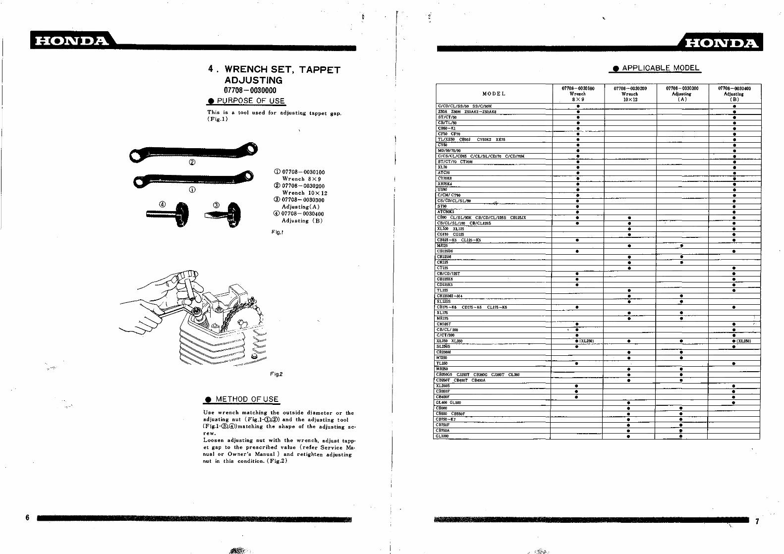
Emm:a _4. WRENCH SET, TAPPET
ADJUSTING07708- 0030000
• PURPOSE OF USE
This is a tool used for adjusting tappet gap.(Fig.1)
(j) 07708-0030100Wrench ax 9
® 07708- 0030200Wrench lOX 12
® 07708- 0030300Adjusting( A)
@ 07708- 0030400Adjusting (B)
Fig.1
Fig.2
• METHOD OF USE
Use wrench matching the outside diameter or theadjusting nut (Fig.l-<D.®) and the adjusting tool(Fig.l-@,@)matching the shape of the adjusting screw.Loosen adjusting nut with the wrench, adjust tappet gap to the prescribed value (refer Service Manual or Owner's Manual) and retighten adjustingnut in this condition. (Fig.2)
r _ .4mmm• APPLICABLE MODEL
07708-0030100 07708-0030200 07708-0030300 07708-oo30~0
MODEL Wrench Wrench Adjusting Adjusting8X9 lOX 12 ( A) (B)
C/CD/CL/SS/SO 55fC/SOM •ZSOA ZOOM Z50AK2 -ZSOAK8 •ST/CT/SO •CB/TL/50 •CB50-Kl •CFSO CF70 •TL/XESO CBSOJ CY50K2 XE75 •CYSO •MD/~/70/90 •C/CS!CL/CD65 C/CL/SL/CD!70 C/CDI70M •ST/CTl10 CT70M •XL70 •ATC70 •CT70K8 •XR75K4 •USOO •C/CMI crn •CS/CD/CL/SL/90 , • •STOO • •ATC90K3 • •CB90 CL/SL/90K CB/CD/CL/125S CB125JX • • •CB/CL/SL/lOO CB/CLlZSS • • •XLiOO XL125 • •CGIlO CG125 • •CB125-K5 CLl25 '5 • •MJ125 • •CB125B6 • •CR125M • •CR125 • •CT125 • •CB/CD/125T • •CBI25K6 • •CDI25K5 • •TLl25 • •CR125M2-M4 • •XLl25S • •CB175-K6 CD175-K6 CLl75-K6 • •XL175 • •MR175 • •CM185T • • ,CB/CLlroo , • •C/CTI200 • •XL250 XL350 • (XL2SOj • • • (XL250)SL250S • •CR250M • •M12,. • •TL250 • •MR250 • •CB250G5 CJ250T CB360G CJ360T CL360 • •CB250T CB400T CB400A • •XL250S • •CB350F • •CB400F • •GL400 GLSOO • •CB500 • •CBSSO CB550F • •CB750-K7 • •CB750F • •CB750A • •GLlOOO • •
6 7 III Jill\
7

~----------------_. ------------------~
This tool is used to remove the wheel bearingretainer when replacing the front or rear wheelbearings. (Fig.! )
• APPLICABLE MODEL
07110-0010100 07110-0010200 07110-0010300 07110-0010401 07110 0010501MODEL Retainer Retainer Retainer Body! A) Body(B)
( A) (B) (e) MI2x 1,5 MI2x 1.0CBl25B6 • •CRl25M • •CRl25 • •CB125K6 • •CBl25T CD125T • •MR175 • •CB/CL/200 • •CB25)-K3 CL250-K3 SL250 CB3S0-K4 CL3S0-K4 SL3S0-K4 • • •XL250 XL350 • •SL250S • •CR25l)M • •MT250 • •TL250 • •MR250 • •CB250GS CJ250T CB360G CJ360T CL360 • • •XL250S • •CIl350F • • •CB400F .' • • •GUOO GL500 • •CBfSO-KS CUSO-KS • • • •CBSOO • •CBSSO CBSSOF • •CB500T • • • •C"'O '. • • •CB7SO-K7 • • • • •CB7SOF • • • •CB7S0A • • •CB7SOK • • • •CB900F • • •GLlOOO • • •CBXlOOO • • •
CD 07710- 0010100Wrench (A)
® 07710-0010200Wrench (B)
® 07710- 0010300Wrench (C)
007710- 0010401Body (A) Screw diameter M12x 1.5
® 07710- 0010501Body (B) Screw diameter M12x 1.0
Fig.!
5. WRENCH SET, RETAINER07710-0010002
• PURPOSE OF USE
@ ®
®
000
@Handle@Shaft
@Hex.agonal portion
Fig.2 Flg.3
• METHOD OF USE
Apply wrench of the correct size matching thefront or rear wheel bearing retainers (Fig.l--cD.@)and the tool matching the screw pitch of the bearing retainer (Fig.l-@or@) as shown in Fig.2.
<Caution>Always select the tool of the correct sizematching the screw pitch of the retainer as theretainer cannot be removed if the size is incorrect.Next insert shaft (Fig.2-@) of tool on which thewrench is set into the wheel bearing and turn handle (Fig.2-(D) until there is no clearance betweenthe wrench, wheel hub and handle.Secure handle and turn the hexagonal portion 07mm diameter) (Fig.2-@) of the shaft and removethe bearing retainer. (Fig.3)
.*Elf the rotation of the shaft is stiff, loosen hand·Ie slightly and try again.When reassembling, set as in the foregoing proce.dure and insert bearing retainer by turning thehexagonal portion of the shaft.
8 PI 311; 'l1lll!111 Iff TIWIi litif mrmiiEI...ilIIlBl.1 PI rlil Rm IIJfli9

------------------~
Fig.3
• APPLICABLE MODEL
07716-0020100 07716-0020202 07716-0020300 07716-0020400 07710-0020500MODEL Wrench Wrench Wrench Wrench Extention
2OX24 20X30 17X27 3OX32 Handle & BarC/CD/CL/SS/50 SS/C/50M •pe/Ps/so pe/PS/SOKI •Z50A ZOOM Z50AK2- ZSOAK8 • •ST/CT/SO •CBSO-KI •CFoo enD •CYSO •M050 •e/cs/eL/CD/55 C/CL/SL/CDI70 C/CD/70M • • (C10, OM)ST/CT/70 CT70M •XL70 •ATC10 •CT10K8 • •XR15K4 • •US90 • •C/CM/CT/go • • •CS/eD/CL/SL/go • • •STOO 'it • •ATC90K3 • •CB/CL/SL/90K CB/CD/CL/125S CBl25JX • •CD/CL/SL/IOO CB/CL!125S • •XLlOO XLl25 • •CS110 • •CGllO CGI25 •CBI25-K5 CLl25-K5 , •MT125 •C812586 •CR125M • •CTl25 •CB125K6 •CDI25K5 •TLl25 •XLl25S •CBI7S-K6 eDI7S-K6 CU7S-K6 •XL175 •MRl1S •CM185T •C200 CT200 •CB200 CLWO •CBZ50-K3 CL250-3 SL250 CBa5(l-K4 CLaso-K4 SL350-K4 •XL250 XL350 • •SL250S • •CR250M • •MT250 • •TL250 • •MR250 • •CS250GS CJ250T CB360G CJ360T CL360 • •CB250T CB400T CB400A • • •XL250S • •CB400F • •GL400 GL500 • • •CB450-K5 CL450-KS • •CBSOOT • •c"SO . • •CB150-K7 • •CB150F • •CB750K • • •CB900F • • •GLlOOO • •CBXlOOO • •
Fig.1
Fig.4
This tool is for loosening or tightening the locknut when disassembling or reassembling the clutch. (Fig.I)
<DFit extension and handle (Fig.l-®.®) to the wrench (Figl-(D-@)of the correct size matchingthe shape and size of the lock nut. (Fig.2) Next, fitwrench onto lock nut and turn the handle to tighten or loosen the lock nut. (Fig.3)
®To raise or bend the loek washer serrations,use end portion of the handle(Fig.l-@)and gradually lift up aU of the serrations. (Fig.4) Whenassembling, always ensure that all of the lockwasher serrations are bent before tightening thelock nut.
6. WRENCH SET, LOCK NUT07716-0020002
• PURPOSE OF USE
<D 07716- 0020100Wrench 20X 24
® 07716- 0020202Wrench 26 X 30
aD 07716--0020300Wrench 17x27
@ 07716- 0020400Wrench 30X 32
$ }07716-0020500
Extention, Handle & Bar
• METHOD OF USE
Fig.2
10 11
~-----------------
,
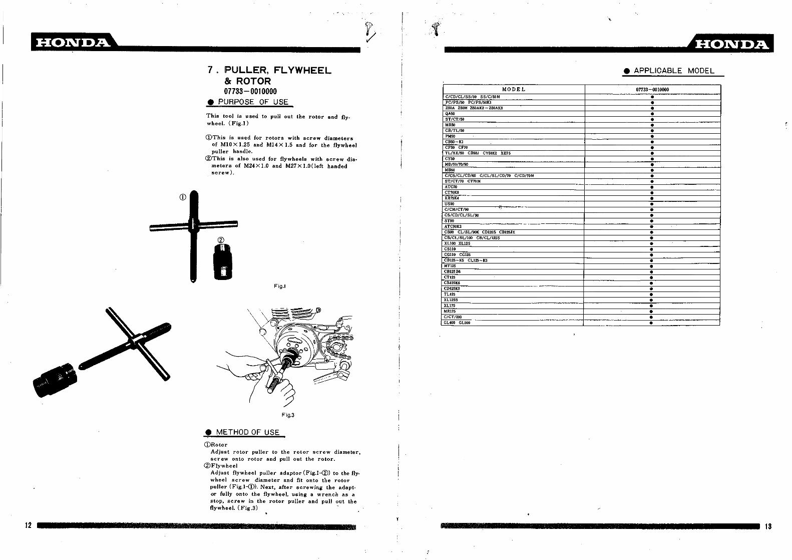
----------------_.~7 . PULLER, FLYWHEEL
& ROTOR07733-0010000
• PURPOSE OF USE
This tool is used to pulJ out the rotor and flywheel. (Fig.I)
CDThis is used for rotors with screw diametersof MIO X 1.25 and M14 X 1.5 and for the flywheelpuller handle.
®This is also used for flywheels with screw dia.meters of M24X1.0 and M27X1.0(Ieft handedscrew).
iFig.1
Fig.3
• METHOD OF USE
CDRotorAdjust rotor puller to the rotor screw diameter,screw onto rotor and pull out the rotor.
@FlywheelAdjust flywheel puller adaptor (Fig.l-@) to the fly·wheel screw diameter and fit onto the rotorpuller (Fig.l-(j). Next, after screwing the adapt·or fully onto the flywheeJ. using a wrench as astop, screw in the rotor puller and puJl out theflywheel. (Fig .3)
+
MODELC/CD/CLISS/SO 55fC/SOMpe/Ps/so fe/PS/SOKIZSOA ZOOM ZSOAK2 - Z50AK8QASOST/eT/SOMRSOCB/TL/50PMSOCB50-KI
CFoo CF70TL/XE!50 CB50J CY50K2 XE1SCYSOMD/sonO/goMB50C/CS/CL/CD/65 C/CL/SL/CD!70 C/CDI70MST/CTI70 CT70MATC10
CT10K8XR15K4USOOC/CM/CT/90CS/CD/CL/SL/90STOOATC90K3CB90 CL/SL/90K CD125S CB125JXCB/CL/SL/IOO CB/CL/l2SSXLlOO XL125CSllOCGllO CGl25CBl2S-K5 CL125-K5MTl2SCB12586CTl25CB125K6CD125K5TL125XL125SXL115MR115C/CT/2OQGL400 GLSOO
• APPLICABLE MODEL
07733-0010000
•••••••••••••••••••••••••••••••••••••••••
12 j 18

~------------$'8. PULLER, ROTOR
07733 - 0020001• PURPOSE OF USE
This tool is used for pulling out the rotor (Fig.1)This is used for rotors with screw diameters ofM16x1.5,M18x1.5, M20X1.5and M22X1.5.
Flg.1
fI
<f)'i<':.,. ~
, '..
------------------~• APPLICABLE MODEL
MODEL 07733-0020001
CR125M •CB/CD/l25T •CB175-K6 CD175-K6 CLl15-K6 •CMI8ST •CB/CL1200 •CB250-K3 CL250-K3 SL250 CB350-K4 CL350-K4 SL350-K4 •XL250 XL350 •SL250S •MT250 •TL250 •MR250 •CB250G5 CJ250T CB360G CJ360T CL360 •CB250T CB400T CB400A •XL250S •CB350F •CB400F •GL400 GLSOO •CB4SO-KS CUSO-K5 •C8500 •C8550 CBSSOF ·f •CB500T •CB650 •CB150-K7 •CB750F •CB750A •
Fig.2
• METHOD OF USE
Set rotor puller to match size of rotor screw,screw in and pull out rotor. (Fig.2)
14 1DIIIIIJIIIIIIIiIIllUIlFT lIlillill III If 1 FE 111111111 111m 15

~ .o _
..,:
------------------~
This tool is used driving valve guides in or outand for cutting the ends of the valve guide(Fig.l)
9 DRIVER IN/OUT SET.VALVE GUIDE07742-0010000
• PURPOSE OF USE
• METHOD OF USE
CDWhen "driving out the valve guideUse a remover (Fig.l-(!),@> matcJi'ing the insidediameter of the valve guide and drive out thevalve guide with a hammer. (Fig.2)
®When cutting the valve guideIf the end of the" valve guide to be driven outhas become sharp, cut the end of the valve guide as per the following procedure to secure sufficient contact area for the remover as therewill be danger of damage to the cylinder if theremover is used in that condition.Fit pilot matching the inside diameter of the va·Ive guide (Fig.l-@-@)to the cutter holder (Fig.1-(1).Place on valve guide as shown in Fig.3 and,turning handle clockwise, cut until sufficient con·tact area is secured for the remover.
@When dring in the valve guideFit driver(Fig.l-@-@)matching the outside diameter of the v,alve guide as shown in Fig.4 anddrive in with a hammer. However, there are some types of vehicles in which the remover (Fig.l--<D.®) is also used for d riving in the valve guide.
<Note>When driving in the valve guide, always drivein to the- exact prescribed height. (see manu:a))
1J(j) 07742-0010100
Remover 5.5® 07742-0010200
Remover 6.6® 07742- 0020100
Driver (A)@ 07742-0020200
Driver (B)® 07742-0020300
Driver (C)® 07742-0020400
Driver (D)® 07742-0030100
Cutter, Valve Guide® 07742- 0030200
Pilot 5.5® 07742-0030300
Pilot 6.6@ 07742-0030400
Pilot, 7.0
Fig.1
@@@
H\@
Fig.2
Fig.4
I~
16 1111 17

~ .(S.U.'{ •
• APPLICABLE MODEL
07742 07742 01142- 07742- 01742 07142 01142 01142- 01742 071420010100 0010200 0020100 "'''5O 0020300 0020400 0030100 0030200 0030300 0030400
MODELDriver Driver
Cutler,Pilot Pilot PilotRelllover ReMOver Driver Driver Valve
5.5 '.5 (A) (8) (C) (D) Guide 5.5 ••• 7.'C/eD/eL/SS/50 5S/C/SOM • • • •PC50/PS/SO PC/PS/SOKl • • • (peSOKl) • •Z50A Z50M Z50AK2-Z50AKS • • • •ST/eT/SO • • • •CB/TL/SO • • • ,.CB50-Kl • • • •CFSO eF70 • • • •TL/XE/50 CB50J CYooK2 XE75 • • • •CYSO • • • •MD/50/70/90 • • • •C/CS/CL/CD/65 C/eL/SL/CD/70 C/CD/70M • • • •ST/CTI70 CT70M • • • •XL70 • • • •ATC10· • • • •CT1OK8 • • • •XR75K4 • • • •US90 • • • •C/CM/CT/90 • • • •CS/CD/CL/SL/90 • • • •STOO • • • •ATC90K3 • • • •CB90 CL/SL/90K CDl255 CB125JX • • • •CB/CL/SL/IOO CB/CL/126S • • • •XLiOO XLlZS • • • •CSlIO • • • •CGIlO CGl2S • • • •CBI25- K5 CL125- K5 • • • •CBl25B6 • • • •CTIZ5. • • • •CB/CD/IZ5T • • • •CB125K6 • • • •CDlZ5K5 • • • •TLl25 • • • •XLl25S • • • •CB175-K6 CD175-K6 CU1S K' • • • •XLl75 • • •CMl85T • • •CB/CL/200 • • • •CB250-K3 CL250 K3 SL250 CBSSO-X4 CL350-K4 SL350-K4 • • • •XL250 XL3S0 • • • •SL250S • • • •TL250 • • • •CB250GS CJ250T CB360G CJ360T CL360 • • •XL250S • • •CBZ50T CB400T CB400A
_ (IN _(EX) • .(IN) .(EX)
CIl350F • • • •CIl400F • • • •GUOO GLSOO • • •CIUSO-K5 CUSO-K5 • • • •CB500 • • • •CB550 CB550F • • • •CB500T • • • •CB650 • • • •CB750-K7 • • • •CB750F • • •CB750A • • •CB750K • • • •CB900F • • • •GLlOOO • • •CBXIOQO • • •
,
------------------_.~10. DRIVER SET, BEARING
07746-0010001• PURPOSE OF USE
This tool is used to drive in ball bearings.There are two types available depending on wherethe baH bearings are used.For driving in the ball bearing inner race.For driving in the ball bearing outer race.
Fig.1
CD 07749-0010000 Handle (A)® 07746-0010100 Outer driver 32X35® 07746-0010200 Outer driver 37X40(1) 07746-0010300 Outer driver 42X47® 07746-0010400 Outer driver 52X55® 07746-0010500 Outer driver 62X68(f) 07746-0010600 Outer driver 72X75® 07746-0040100 Pilot 10® 07746-0040200 Pilot 12@> 07746- 0040300 Pilot 15@ 07746-0040400 Pilot 17@ 07746-0040500 Pilot 20@ 07746-0041000 Pilot 22® 07746- 0040600 Pilot 25@ 07746-0040700 Pilot 30@ 07746- 0040800 Pilot 35@ 07746-0040900 Pilot 40@ 07746-0030100 Handle (C) 40@ 07746-0030200 Inner driver 25® 07746-0030300 Inner driver 30® 07746-0030400 Inner driver 35@ 07746-0020100 Handle (B) 22@ 07746-0020200 Inner driver 15@ 07746-0020300 Inner driver 17@ 07746-0020400 Inner driver 20
18 It I 19

r
···· __·· __····_--~-~---r-1-~---~'-----~------------------- ._-----------------~
Fig.2
Fig.4
• METHOD OF USE
1. When driving in the ball bearing outer race.(Example) Bearings driven into the wheel hub.Place outer driver (Fig.l-®-CV) matching thebearing size. pilot (Fig.l-®-@) and handle(Fig.2) onto the bearing to be dr~ven in anddrive in with a hammer.( Fig.3)
Fig.3
2. When driving in the ball bearing inner race.(Example) Bearings pressure-inserted into the'crank shaft.Place inner driver matching the bearing size(Fig.1-@l-®or@-@) and the handle (Fig.@Ioror@) onto the bearing race(FigA) and drive inwith a hammer.(Fig.5) There are also instancesin which the handle only is used to drive in thebearing race depending on the size of the bearing.(Refer to Tadle of Applications)
Fig.5
• APPLICABLE MODEL
Inner race (.) Outer race (-)
Ball Bearing Inner driver Ha"~e Inner driver HaRd~eOuter driver Pilot "m·
No. 15 17 20 22 25 30 35 40 32x35 37X40 42X47 52X 55 62X68 72X75 10 12 15 17 20 22 25 30 35 40 d1.A
. 6002 • • • • •6003 • • • • •6004 •• • • •6005 • • • • •6006 • • • • •6007 •• • • •6008 • • • •6201 • • •6202 • • • • •6203 • • • • •6204 • • • • •62/22 •620'5 • • • • •6206 • • • • •6207 • • • • •6208 •6300 • • •6301 • • •6302 • • • • •6303 • • • • •6304 • • • • •63/22 • • • •6305 • • • • •6306 • • • • ).6307 • • i
6308 •6403 • • • • •6404 • • • • •6405 • •6406 • •6407 • •6408 •6902 • •6903 • •6904 • • • • •6905 • • • • •6906 • • • • •6907 • • • • •6908 • • • •
16002 • • • • •16003 • • • • •16004 • • • • •16005 • • • • •16006 • • • • •16007 • • • • •16008 • • • •
'•.~14l.':"-:
20 1 21

~ .o _-----------------_.~
• METHOD OF USE
This tool is used when driving in the front forkoil seal. (Fig.I)
28
• APPLICABLE MODEL
07747-0010100 07747-0010200 07747-0010300 07747-0010400 07747-0010500 07747-0010600MODEL
Body A.T.T.( A) A.T.T.(B) A.T.T.(C) A.T.T.(D) A.T.T.(E)
C/eD/CLlSS/sO 55fC/SOM • (CL/SS50) • (CL/SSSO)STSO CT50 • •MR50 • •CB/TL/50 • •C850-Kl • •TL/XE/SO CB50J CY50K2 XE75 • •CY50 • •MD/sono/eo • •MB50 • •C/CS/CL/CD/65 C/CL/SL/CDI70 C/CD/70M • •ST/CT1a CT10M • •XL70 • •XR75K4 • •CS/CD/CL/SLf90 • •BT90 • •CBOO CL/SL/90K CD125S CB125JX • • (90ce) • (I25cclCB/CL/SLIlOO CB/CL/1255 • • (loocc) • (l25cc)XLlOO XLl25 • •CSllO • •CGllO CG125 • •CB125- K5 CLI25- K5 • •MTl25 • •CBl2586 • •CRI25M • •CR125 • •CT125 • •CB/CD/125T • •CB125K6 • •CDl25K5 • •TLl25 • •XLl25S • •CR125R • •CR125M2-M4 • •CB175-K6 CD175-K6 CLl75-K6 • •XLl75 • •MR175 • •CMIS5T • •CB/CL/200 • •CB250-K3 CL250-K3 SL250 CB3S0-K4 CL350-K4 SL3S0-K4 • ,XL250 XLaso , •CR250M •MT250 •TL250 •MR250 •CB250G5 CJ250T C8360G CJ360T CL360 •SL250S •C8250T C8400T C8400A •XL250S •CB3S0F •C....F •GL400 GLSOO •C84SO- K5 CL450- K5 •CB500 • •CBSSO CBS50F • •C"""'T • •CB650 • •CB7SO-K7 • •CB750F • •C8750A • •C8750K • •C8900F • •GLlOOO • •CBXlOOO • •
i
II
1'1
Fig.3
Q)07747-0010100 Body
( Drive~in depth 19.5_)14.0_
@07747-0010200 A.T.T.(A)@07747-0010300 A.T.T.(B)@O7747-0010400 A.T.T.( C)@O7747-0010500 A.T.T.(D)@07747-0010600 A.T.T.(E)
Fig.1
Fit A.T.T.(Fig.I-@-@) matching the front forkpipe diameter(inner tube) and the fork bottomeasediameter (outer tube) onto the tool proper (Fig.l-(1)) and drive in the oil sea) whiJe guiding withthe fork pipe. (Fig.3)
<Note>As the oil seal may be driven in to 14mm. and 19.5mID from the edge of the bottom of the fork casingon certain types of vehicles in which this depth isfixed (see manual), select and drive in to the prescrihed depth.( Fig.2)
11. DRIVER SET, FRONT FORKOIL SEAL07747-0010000
• PURPOSE OF USE
CD
•00000
Fig.2
Q)07747- 001010019.5_)14.0_
®O7747-0010200 A.T.T.(A)@07747-0010300 A.T.T.(B)@O7747-0010400 A.T.T.( C)@O7747-0010500 A.T.T.(D)@O7747-0010600 A.T.T.(E)
22

iI.!j
II
III 25
!
------------------~07757-0010000
•••••••••••••••••••••••••••••••••••••••••••••••••••••••••••••
• APPLICABLE MODEL
CB750-K7
CB750F
CB750A
CB750K
CB900F
GLlOOO
CBXlOOO
MODELC/CD/CLISS/SO SS/C/50MZ50A Z50M Z50AK2- Z50AK8QASO
ST/CT/SOCB/TLl50CBSO-KI
CFoo eF7QTL/XE/SO CB50J CY50K2 XE75
CYSO
MD/SOI10/90C/CS/CL/CD/65 C/CL/SL/CDI70 C/CDI70MST/CT170 CT70MXL70ATC10CT70KSXR15K4US90C/eM/eT/goCS/CD/CL/SL/90ST90 ~.i
ATC90K3CBOO CL/SL/90K CDl25S CBI2SJXCB/CLlSLlIOO CB/CL/IZS5
XLiOO XLl25
CSIlOC;:G1l0 CGl25
CB12S-KS CL125-KSC812586CTl25CD/CO/12STCB12SK6CD125K5TL125
XL125SCB115-K6 CDJ75-K6 CL115-K6
XLl75
CMISSTC/CTI200CB/CLI200CB2&I-K3 CLZ50~K3 SL250 CB350~ 1(4 CL3S0-K4 5L3S0-K4
XL250 XL350TL250
CB250G5 CJ250T CB360G CJ360T CL360
5L2505CB250T CS400T C840M
XL250SCB350FCB400FGUOO GL500CB450-KS CUSO-K5CBSOOC8550 CBssoFCB500TC8650
,,.
If
I,
Fig.2
• METHOD OF USE
This tool is used to compress the valve springwhen removing or installing the valve cotter. Asthis tool is provided with a "quick lock" device,working time is greatly shortened compared tothe conventional tools_ (Fig.I)
Fig.1
12. COMPRESSOR,VALVE SPRING07757 - 001 0000
• PURPOSE OF USE
ill Frame boss® Pressure screw
set position@ A.T.T.@ Lever of the quick
Jock device(§) Lock lever® Handle
ill Match pressure screw set position (Fig.l-@) tothe face of the frame boss(Fig.I-(!).
® Fit A_T.T. (Fig.l-@) onto the valve spring retainer and press lock lever (Fig.I-(§) onto the topof the valve by manipulating the lever of thequick lock device (Fig.I-@).
@ Turn handle (Fig.I-@) and screw in while pushingthe lock lever in the "Lock" direction. (Fig.2)(In this instance, it will lock automatically whenscrewed in slightly.)
@ Remove valve cotter, loosen pressure screw,release lever of the quick lock device and pullout lock lever fully.
@
~-----------------
24

mm!i:D... ~ _13. DRIVER SET, PIN
07744-0010000• PURPOSE OF USE
This tool is to drive the spring pin in or out.(Fig. I)
-----------------~• APPLICABLE MODEL
MODEL 07744-0010100 07744-0010200 07744-00103011 07744-0010400 07744 0010500 07744 0010600Pin 2.5 Pin 3.0 Pin 3.5 Pin 5.0 Pin 6.0 Pin 8.0
ST/CT/SO •CF50 CF10 •ST/CT/70 CT70M •GUOO GLSOO •CB750A •CBXl000 •
Q)
@--------®
@
CD07744-0010100 Pin 2.5®O7744- 0010200 Pin 3.0@07744-0010300 Pin 3.5@O7744-0010400 Pin 5.0@07744-0010500 Pin 6.0@07744-0010600 Pin 8.0
Fig.1
Fig.2
• METHOD OF USE
Fit pin driver (Fig.l-(!)-@), which matches theoutside diameter of the spring pin. onto the pinand drive the spring pin out with a hammer.(Fig.2)
26 27

• APPLICABLE MODEL
MODEL 07959-3290001C/CD/CL/SS/50 55fC/SOM •pe/PS/SO pe/PS/SOKt •STI.CT!SO •CB/TL/50 •NC50 •NF50 NF15 •CB50-Kl •CF50 CF70 •TL/XE/50 CBSOJ CY50K2 XE75 •CY50 •MD!50170/90 •MB50 •FM50 •C/CS/CL/CD/65 C/CL/SL/CD/70 C/CD/70M •ST/CTI10 CT70M •XL70 •CT70K8 •XR15K4 •C/CM/CT/90 •CS/CD/CL/SL/90 •S1W •CB90 CL/SL/90K C01255. CBl25JX •CB/CL/SL/IOO CB/CL/125S •XLlOO XL125 •C5110 •CCIIO CG125 •CB125-K5 CLl25-KS •MT125 •C812586 •CBl25K6 •CDl25K5 •TLl25 •XLl25S •CR125M2-M4 •CR125 •CTl25 •CB175-K6 CDl15-K6 CLI75- KG •XL175 •CMISST •C/eT/Zoo •CB/CL/200 •CB250-K3 CL250'~K3 SL250 CB350-K4 CL350-K4 SL350-K4 . •XL250 XL350 •MT250 •TL250 •MR250 •CB250G5 CJ2SOT CB360G CJ360T CL360 •SL250S •CB2S0T CB40QT CB40QA •XL250S •CB350F •CB40QF •GL400 GLSOO •CB450-K5 CL450-K5 •CBSOO •CB550 CBSSOF •CBsooT •CB650 •CB150-K1 •CB150F •CB150A •CB1SOK •CB900F •GLIOOO •C9XlOOO •
----------------_.~r¥t,:lI,I,~-
CDAdjusting nut@P;n@Handle
This tool is used to compress the rear cushionspring to remove or install the spring seat stopper, and to disassemble or assemble the rearcushion. (Fig.I)
Fig.3
• METHOD OF USE
14. DIS/ASSEMBLY TOOL,REAR CUSHION07959 - 329000I
• PURPOSE OF USE
CD
<D Set adjusting nut (Fig.I-CD) to the outside dia·meter of the upper case of the rear cushionand fit onto the rear cushion. (Fig.2)
® Insert pin (Fig.l-®) into the top portion of therear cushion to prevent rotation.
@ Turn handle (Fig.l-@) to compress the springportion of the rear cushion, remove the springseat stopper and disassembie.( Fig.3)
@ ReinstaUation may be carried out by the sameprocedure.
rFig.2
~-----------------
28 II 7 liP 29

~--------------_/- -----------------_.~
• (ONLY CL90)
•••••••• ,• i
••.(R·W).(R·W).(R·W).(R·W)
••••••••••••••••••••••••••
31
07701-0020300
( C)5.8X6.1
••• (ONLY MDno 90)
.(p.W)
• (F.W).(F·W)
.(F·W)
•
•
•
••••••••••
•
07701-0020000
(B) 4.5X5.1
• APPLICABLE MODEL
••• (ONLY MD50)
•
07701-0020100
(A) 4.IX4.5
•••
MODEL
Use wrench(Fig.I-<D-@)of the correct size forthe spoke nipples and tighten or loosen the spokes.(Fi;.2)When controlling the torque. tighten the spokenipples to the correct torque with a torque wrench after tightening all uniformally by hand. (Fig3)Also. although the method of calculating the tightness torque is as shown in Fig.4. refer to themanual for the prescribed value.
TLl25XLl25SCR125M2-M4CRl25RCB175-K6 CD175-K6 CLl75-K6
XLI75MR175CMI85TC/CT/200CB/CL/2ooCB250-K3 CL250-K3 SL250 CB3!»-K4 CL350-K4 SL350-K4XL250 XL350CR250MMT250TL250MR250CB250G5 CJ250T CB360G CJ360T CL36081.2505
~~~!r_~,~400T CB400A
~~._~-~-CB3BOIICU400Y . ~. . ''''V'_~''_
CB4&O-KII-·C"t:.tiO',"I('ft , ..._- -~~
CB500 .~-="~.':~:"."~~~ -- _CBSSO CB55W
i-i:C"B"'::;;cT'-;;;c- _CB750-K7
~BI750FE~~=·:=:__ ~-·--CB750A .. - .. .- ...."'_.~~CB750K ..,-_..,,-GLlQOO
C/CD/CUSS/50 SS/C/50MPC/PS/50 PC/PS/50KICT50CBITU50NC/50TL/XE/50 CB50J CY50K2 XE75PA50CB50-KIMD/50/70/90PM50C/CS/CL/CD/65 C/CL/SL/CDI70 C/CDI70MXL70XR75K4C/CM/CT/90CS/CD/CL/SL/90CB90 CUSU90K CD125S CB125JXCB/CL/SL/IOO CB/CLl125SXLiOO XL125CSllOCGllO CGl25CB125-K5 CLl25- K5~~===~=~~ =~~=~~~~~~=~~~~.~ ..~~~25
CBl25B6 ~~_
CRI25MCRI25CT125CBI25K6CDl25K5CBl25T C0l25T
• METHOD OF USE
I!I
Fig.1
Fig.3
When a torque wrench isused for a nipple spanner.the actual torque appliedto the spoke nipple willnot be indicated.Calculate the actual torqueas follows.A=Effective length of the
torque wrenchB = Effective length of the
nipple spanner(Table.l)R=Indicated valueT=Actual torque value app
lied to the spoke nippleA+B T-A-=If
Table.1
CD07701-0020100 (A) 4.IX4.5@07701-0020200(B)4.5X5.1@07701-0020300 (e) 5.8X6.1
Spanner Size B Size4.1mm, 4.5mm 15.7mm
5.1mm, 15.5mm5.8mm, 6.1mm 15.0mm
15. SPANNER SET, NIPPLE07701 - 0020000
• PURPOSE OF USE
This tool is used to adjust the tension of the spokes by turning the spoke nipples. (Fig.I)It is also possible to control the tightness torqueby using a torque wrench in combination.
Fig.4
CD
r---t
\I
iE-B A
U I}\ I E- - I
90·
Fig.2
30

m:m:D _
pjii6w TO ORDER.. :,J-,
o Honda Common Service Tools are available through the same parts order channelas Honda Special Service Tools.
o Please specify tool numbers and quantities required when placing orders oncommon service tools and inspecting the tool as the case may be used by anothertool as the same work.
o Immediately contact your dealer if tools are defective at time of delivery. Youwill be furnished with new tools if they appear to Honda, upon inspection, tohave been defective in material or workmanship.
32

,


