20
® Ready to Run 1/5-Scale Brushless EP Motorcycle Ready to Run 1/5-Scale Brushless EP Motorcycle

®
Ready to Run 1/5-Scale Brushless EP MotorcycleReady to Run 1/5-Scale Brushless EP Motorcycle

2
INCLUDED TOOLS
REQUIRED TOOLS
ITEMS REQUIRED FOR OPERATION
2mm Wrench
Phillips ScrewdriverDTXR0124
Flat Blade ScrewdriverDTXR0102
Cleaning Brush
Hex WrenchesDTXR0288 (1.5mm) DTXR0291 (3mm)
Onyx™ 200 Peak ChargerDTXP4200
6-Cell BatteryDTXC2054
Charge AdapterDTXC2209
Needle Nose PliersDTXR0300
ThreadlockerDTXR0288

3
SAFETY PRECAUTIONS
When these safety precautions are followed, the DX450 will provide years of enjoyment. Use care and good sense at all times when operating this radio controlled motorcycle. Failure to use this vehicle in a safe, sensible manner can result in injury or damage to property. You and you alone must ensure that the instructions are carefully followed and all safety precautions are obeyed.
• Do not operate the DX450 near people. Spectators should be behind the driver or at a safe distance away from the bike.
• Make sure to read the instructions included with the battery and charger before charging the battery.
• Do not leave any charger unattended during charging. If the battery or charger become hot at any time, disconnect the battery from the charger immediately! Failure to do so may cause permanent damage to the charger and battery and may cause bodily harm or property damage.
• Do not cover the air intake holes on the charger during charging. This may cause the charger to overheat.
• Do not allow the electronic speed control (ESC) or other radio equipment to come into contact with moisture. Water can cause electronics to short out and can cause permanent damage.
• Always turn on the transmitter before turning on the ESC.
• Always turn off the ESC before turning off the transmitter.
• Allow the motor and ESC to cool before each run.
SPECIFICATION AND DESCRIPTION CHANGES
All pictures, descriptions and specifi cations found in this instruction manual are subject to change without notice. DuraTrax maintains no responsibility for inadvertent errors in this manual. Visit duratrax.com for the latest updates and information for your model.
HELPFUL HINTS
• Avoid working over a deep pile carpet. If you drop a small part or screw, it may be diffi cult to fi nd.
• Place a mat or towel over your work area. This will prevent parts from rolling off and protect the work surface.
• Avoid running the motorcycle in cold weather. The plastic and metal parts can become brittle at low temperatures. In addition, grease and oil become thick, causing premature wear and poor performance.
• Test fi t all parts before attaching them permanently.
STRESS-TECH™ PARTS GUARANTEE
We have engineered the DX450 to take the rough and tumble abuse that makes R/C fun. We are so confi dent of the quality and durability of the Stress-Tech plastic parts that we will replace any Stress-Tech plastic part you break during the fi rst 12 months you own the motorcycle. Just send in the part to us and we will send you a FREE replacement. Please see the parts list for the items covered under the Stress-Tech guarantee.
To receive your free replacement part please send the following to the Hobby Services address listed under the warranty.
❏ 1. The broken part must be included.
❏ 2. The part number and description of the broken part.
❏ 3. Copy of the dated invoice or purchase receipt.
❏ 4. Your name, phone number and shipping address.
WARRANTY
• DuraTrax® guarantees this kit to be free from defects in both material and workmanship at the date of purchase. DuraTrax will warranty this kit for 90 days after the purchase date. DuraTrax will repair or replace, at no charge, the incorrectly made part.
• Make sure you save the receipt or invoice you were given when you bought your model! It is your proof of purchase and we must see it before we can honor the warranty. Further, DuraTrax reserves the right to change or modify this warranty without notice.
• In that DuraTrax has no control over the fi nal user assembly or material used for fi nal user assembly, no liability shall be assumed nor accepted for any damage resulting from the use by the user of the fi nal user-assembled product. By the act of using the user-assembled product, the user accepts all resulting liability.
To return your DX450 for repairs covered under warranty, you should send your motorcycle to:
Hobby Services3002 N. Apollo Drive Suite 1Champaign, Illinois 61822Attn: Service DepartmentPhone: (217) 398-0007
9:00 am–5:00 pm Central Time M-FE-mail: [email protected]
hobbyservices.com
If you are not prepared to accept the liability associated with the use of this product, you are advised to return this kit immediately in new and unused condition to the place of purchase.
REPAIR SERVICE
Repair service is available anytime.
• After the 90 day warranty, you can still have your DX450 repaired for a small charge by the experts at DuraTrax’s authorized repair facility, Hobby Services.
• To speed up the repair process, please follow the instructions listed below.
❏ 1. Under most circumstances return the ENTIRE vehicle. The exception would be sending in a Stress-Tech part. See the instruction under the Stress-Tech Guarantee.
❏ 2. Make sure the transmitter is turned off, and all of the batteries are removed.
❏ 3. Send written instructions which include: a list of all items returned, a THOROUGH explanation of the problem, the service needed and your phone number during the day. If you expect the repair to be covered under warranty, be sure to include a proof of date of purchase (your store receipt or purchase invoice).

4
TRANSMITTER PREPARATION
STABILIZER BAR INSTALLATION
3x8mm BH Screws
ASSEMBLE THE BIKE STAND
• Slide off the batttery tray door and install four “AA” batteries. Make sure the polarity is correct.
• Turn on the transmitter and check the battery light. If the red light glows steadily, the batteries have enough voltage. If the red light blinks, the batteries are low and should be replaced.
• Raise the antenna at the top of the transmitter.
RED BATTERYLIGHT
• The receiver should be factory bound to the transmitter. However, if you ever need to bind, follow these steps:
1. Turn on the transmitter.2. Turn on the receiver via the switch on
the ESC. If the receiver is not bound, the LED light will not be on.
3. Push and hold the bind button on the receiver until the light glows red.
4. Release the bind button.5. If the binding is successful, the LED
will fl ash once and then remain ON.
2. Make sure the collar is mounted on the center of the bar and tight the set screw.
3. Bend the rod and insert the ends into the bike.
4. Secure the bar to the bike using set screws.1. Slide the metal collar
onto the stabilizer bar.
4x4mm Set Screw(use threadlock)
3x3mm Set Screw(use threadlock)
4x4mm Set Screw(use threadlock)
4x4mm Set Screw(use threadlock)
4x4mm Set Screw(use threadlock)

5
Note: Rider assembly requires ascrew, washer and nut in alllocations. Insert screw throughboth halves from the outside.Install the washer and nut from the inside.
1
2
4
78
3
5
6
2x6mm BH Screws
2x5mm Washers
2mm Nuts
4mm E-clips
3x6mm BH Screws
3x8mmWashers
Position chestplate“inside” the rider.
Note: Assemble the riderfigure in the correct order.
RIDER ASSEMBLY

6
BATTERY INSTALLATION
• Remove the body clips from the battery door posts and open the door.
• With the ESC “off”, plug the battery into the ESC lead.
• Install the battery into the battery holder, close the battery door and secure it in place with the body clips.
STEERING SETUP
The Dirt Bike comes with a CG Steering System (counter-steering) where the directionbetween the transmitter steering wheel and the Dirt Bike’s front wheel are opposite.
LEFT NEUTRAL RIGHT
• Tuck the battery/ESC leads into the pocket in the battery holder.

7
IMPORTANT OPERATION NOTES
To start a right turn, gentlyturn the transmitter to theright. The bike will lean tothe right.
The best place to operate your dirt bike is on an parking lot, baseball diamond or at your local R/C track.For better stability, be sure to get the gyro spinning before launching the dirt bike.
BEFORE the cycle. Always turn the cycle off before the transmitter.
until you get used to the way the cycle handles.
gyro, making the cycle more stable at low speeds.
For easier starts,use the bike standas shown.
If the stabilizer bar touchesthe ground, the bike will notturn well. Return the transmitterwheel to neutral to lift the bike
Display
To Start
When you want to go straightagain, turn the transmitterwheel in the opposite direction of the turn.
more steering.Longer stabilizer bars (250mm) are better

8
SHOCK OIL
The weight can be adjusted by adding or removingweights in the flywheel:
by using different weight shock oil in the

9
Note: The direction ofthe one-way bearing.
The following section is provided to help you with maintenance and repairsto your DX450. Pay extra attention to the notes and tips for proper assembly.
3x8mm FH Screws
6x13mmBall Bearing
2.5x8mm FH Screws
5mm E-clip
6x10mm Ball Bearings
1
2
3
MAINTENANCE GUIDE
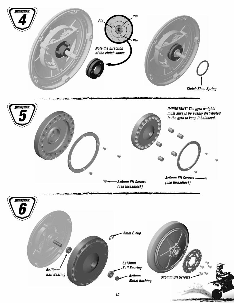
10
Note the directionof the clutch shoes.
IMPORTANT! The gyro weights must always be evenly distributedin the gyro to keep it balanced.
3x6mm BH Screws
3x6mm FH Screws(use threadlock)
3x6mm FH Screws(use threadlock)
5mm E-clip
6x13mmBall Bearing6x13mm
Ball Bearing 6x9mmMetal Bushing
Pin
Pin
Pin4
5
6
Clutch Shoe Spring

11
NOTE: Make sure the leftand right are the same.
NOTE: Make sure the left andright chain adjustment are the same.
1 0.5 01 0.5 0
Keep chain clean & oiled!
Keys into the 6x13mmball bearing.
6x13mmBall Bearing
3x8mm BH Screws
5mm E-clip
5mm E-clip
4mm Set Screw(use threadlock)
6x13mmBall Bearing
6x13mmBall Bearing
Keys into the 6x13mmball bearing.
5mm E-Clip
5mmE-Clip
3x6mmBH Screw
3x8mmWasher
3x8mm Washer
3x6mm BH Screw6x13mm Ball Bearing
4x10mmWasher
6x13mmBall Bearing
4x16mm SHC Screw(use threadlock)
4x16mm SHC Screw(use threadlock)
4x10mm Washer
7
8
9

12
2mm O-Ring
4mm E-clip
4mm E-clip
3mm Nut(use threadlock)
3x6mmBH Screw
3x6mmBH Screws
3x12mm SHC Screw(use threadlock)
4x12mm SHC Screw(use threadlock)
8mm O-Ring
5x10mmBall Bearing
5x10mmBall Bearing
10
11
12

13NOTE: Do not overtighten!
4mm Locknuts
4x25mmSHC Screws
Note theorientationof the servo.
6x13mmBall Bearing
6x13mmBall Bearing
4x12mm SHC Screw(use threadlock)
4x10mmWasher
3x8mmWashers 3x12mm BH Screws
4x10mmWasher
3x6mmBH Screws
4x12mm SHC Screw(use threadlock)
3x6mm BH Screws
13
14
15

14
Remove3 arms.
3x6mm BH Screws
2.5mm Locknut
3x16mmSet Screw(use threadlock)
3x10mmBH Screw
3x16mm Set Screw(use threadlock)
3x8mm BH Screws(use threadlock)
3x8mm BH Screw(use threadlock)
3x8mm BH Screw(use threadlock)
4mm
3x3mm Set Screw(use threadlock)
2.5x12mm BH Screw
3x3mm Set Screw(use threadlock)
Screw includedwith servo.
Approximately 27°17mm
3x8mm BH Screws16
17
18
17mm
4mm

15
2
1
3mm Locknut
19
20
21
9mm O-ring
Shock Oil
7mm C-clip
3x8mmBH Screws
3x40mmBH Screw
3mm Locknut
3x6mmBH Screws
3x6mmBH Screws
3mm O-ring
4mm E-clips
3mm O-ring
Fill the shock body with shock oil. Workthe shock shaft up and down in the shock.
Install the shock cap. Push the shock shaftto the top of the shock body. Slowly tightenthe shock cap. Wipe off any excess oil.
3mm Nut

16
3x8mmScrews
3x20mmScrews
3x16mmSet Screws
(use threadlock)
Receiver
3x10mmBH Screw
5mm E-clip
2x12mm Pin
3x8mmBH Screws
3x8mm BH Screws
22
23
24 25
4mm
3x8mmBH Screw
Double-sided Tape
ESC
Double-sided Tape

17
Motor ESC
3x8mm BH Screws(use threadlock)
3x8mm BH Screws(use threadlock)
3x8mm BH Screw3x8mm Washer
3x8mm BH Screw
Use threadlock
3x8mm Washer
3x8mm Washer
3x3mm Set Screw(use threadlock)
Motor
Tighten the screw with one sheet ofpaper inserted between both gears.
Red (+)Black (–)
Blue
Red (+)Black (–)Blue
3x8mm Washers
26
27
28Use threadlock

18
NOTE: Make sure thecollar is mounted inthe center of the rod.
3mm Nut
3x8mmBH Screws
3x12mm BH Screw(Do NOT overtighten!)
2.5x20mmBH Screw
2.5x20mm BH Screw
29
30
314x4mm Set Screw(use threadlock)
3x3mm Set Screw(use threadlock)
4x4mm Set Screw(use threadlock) 3x8mm BH Screws
4x4mm Set Screw(use threadlock)
4x4mm Set Screw(use threadlock)
3x8mmBH Screws
3x8mmBH Screws
3x8mmWasher
3x8mmWasher
3x8mmWashers

19
OTHER ITEMS AVAILABLE
DuraTrax Evader EXT EP ST RTRDTXD29**
DuraTrax 1/18 Vendetta SC RTRDTXD17**
Heli-Max Novus CX 2.4GHz Nano Sized Coaxial RTF HeliHMXE0803
duratrax.com
duratrax.com
helimax-rc.com
Copyright © 2009DTXZ1150 forDTXD02xx


