1645 Lemonwood Dr. Santa Paula, CA, 93060 USA Toll Free: (800) 253-2363 Telephone: (805) 933-9970 bendpak.com Rotary-Screw Air Compressor Installation and Operation Manual Manual P/N 5900090 — Manual Revision A — September 2019 Model: • RS7580V-601 Engineered by BendPak Inc. in Southern California, USA. Made in China. ⚠ DANGER Read the entire contents of this manual before using this product. Failure to follow the instructions and safety precautions in this manual can result in serious injury or death. Make sure all other operators also read this manual. Keep the manual near the product for future reference. By proceeding with setup and operation, you agree that you fully understand the contents of this manual.
Installation and Operation Manual Manual P/N 5900090 — Manual Revision A — September 2019
Model:
• RS7580V-601
Engineered by BendPak Inc. in Southern California, USA. Made in China.
⚠ DANGER Read the entire contents of this manual before using this product. Failure to follow the instructions and safety precautions in this manual can result in serious injury or death. Make sure all other operators also read this manual. Keep the manual near the product for future reference. By proceeding with setup and operation, you agree that you fully understand the contents of this manual.
Manual. RS7580V-601 Rotary-Screw Air Compressor, Installation and Operation Manual, Manual Part Number 5900090, Manual Revision A, Released September 2019.
Trademarks. BendPak and the BendPak logo are registered trademarks of BendPak Inc. All other company, product, and service names are used for identification only. All trademarks and registered trademarks mentioned in this manual are the property of their respective owners.
Limitations. Every effort has been made to ensure complete and accurate instructions are included in this manual. However, product updates, revisions, and/or changes may have occurred since this manual was published. BendPak reserves the right to change any information in this manual without incurring any obligation for equipment previously or subsequently sold. BendPak is not responsible for typographical errors in this manual. The latest version of the manual for this product is available on the BendPak website.
Warranty. The BendPak warranty is more than a commitment to you: it is also a commitment to the value of your new product. Contact your nearest BendPak dealer or visit www.bendpak.com/support/warranty for full warranty details. Go to bendpak.com/support/register-your-product/ and fill out the online form to register your product (be sure to click Submit).
Safety. Your product was designed and manufactured with safety in mind. However, your safety also depends on proper training and thoughtful operation. Do not install, operate, maintain, or repair the unit without reading and understanding this manual and the labels on the unit; do not use your unit unless you can do so safely!
Owner Responsibility. In order to ensure operator safety and maintain your product properly, it is the responsibility of the product owner to read and follow these instructions: • Follow all installation, operation, and maintenance instructions. • Make sure product setup and use conforms to all applicable local, state, and federal codes, rules, and
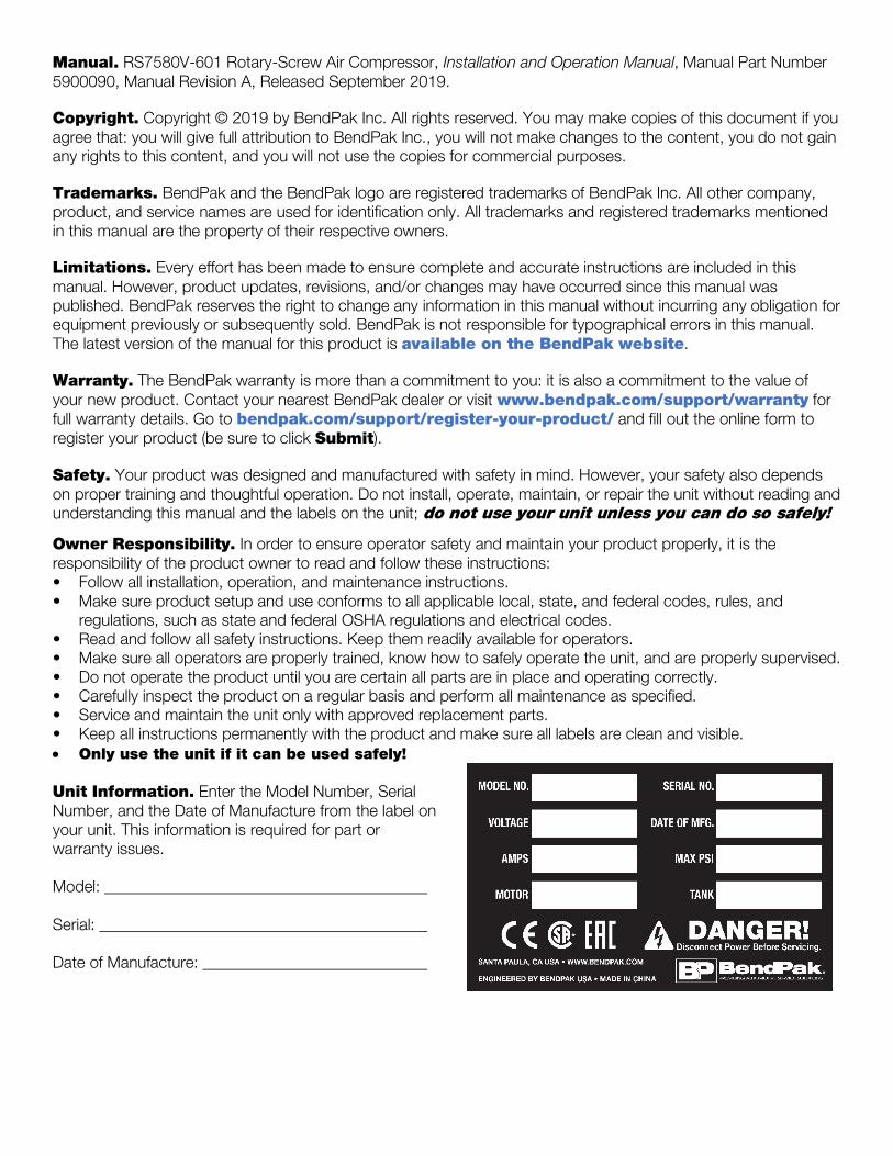
regulations, such as state and federal OSHA regulations and electrical codes. • Read and follow all safety instructions. Keep them readily available for operators. • Make sure all operators are properly trained, know how to safely operate the unit, and are properly supervised. • Do not operate the product until you are certain all parts are in place and operating correctly. • Carefully inspect the product on a regular basis and perform all maintenance as specified. • Service and maintain the unit only with approved replacement parts. • Keep all instructions permanently with the product and make sure all labels are clean and visible. • Only use the unit if it can be used safely! Unit Information. Enter the Model Number, Serial Number, and the Date of Manufacture from the label on your unit. This information is required for part or warranty issues. Model: Serial: Date of Manufacture:
Introduction This manual describes the Hush-Quiet RS7580V-601 Rotary-Screw Air Compressor, which efficiently and reliably creates, stores, and distributes pressurized air for your facility. Pressurized air can be used to power pneumatic tools, operate spray equipment, inflate tires, and many other things.
More information about the full line of BendPak products is available at bendpak.com.
This manual is mandatory reading for all RS7580V-601 users, including anyone who sets up, operates, maintains, or repairs it.
⚠ DANGER Be very careful when setting up, operating, maintaining, or repairing this equipment; failure to do so could result in property damage, product damage, injury, or (in very rare cases) death. Make sure only authorized personnel operate this equipment. All repairs must be performed by an authorized technician. Do not make modifications to the unit; this voids the warranty and increases the chances of injury or property damage. Make sure to read and follow the instructions on the labels on the unit.
Keep this manual on or near the equipment so that anyone who uses or services it can read it.
If you are having issues, refer to the Troubleshooting section of this manual for assistance.
Technical support and service is available from your dealer, on the Web at bendpak.com/support, by email at [email protected], or by phone at (800) 253-2363, extension 196.
You may also contact BendPak for parts replacement information (please have the model and serial number of your unit available) at (800) 253-2363, extension 191.
RS7580V-601 Rotary-Screw Air Compressor 4 P/N 5900090 — Rev. A — Sept. 2019
Shipping Information Your equipment was carefully checked before shipping. Nevertheless, you should thoroughly inspect the shipment before you sign to acknowledge that you received it.
When you sign the bill of lading, it tells the carrier that the items on the invoice were received in good condition. Do not sign the bill of lading until after you have inspected the shipment. If any of the items listed on the bill of lading are missing or damaged, do not accept the shipment until the carrier makes a notation on the bill of lading that lists the missing and/or damaged goods.
If you discover missing or damaged goods after you receive the shipment and have signed the bill of lading, notify the carrier at once and request the carrier to make an inspection. If the carrier will not make an inspection, prepare a signed statement to the effect that you have notified the carrier (on a specific date) and that the carrier has failed to comply with your request.
It is difficult to collect for loss or damage after you have given the carrier a signed bill of lading. If this happens to you, file a claim with the carrier promptly. Support your claim with copies of the bill of lading, freight bill, invoice, and photographs. Our willingness to assist in helping you process your claim does not make us responsible for collection of claims or replacement of lost or damaged materials.
Safety Considerations Read this manual carefully before using your new product. Do not set up or operate the product until you are familiar with all operating instructions and warnings. Do not allow anyone else to operate the product until they are also familiar with all operating instructions and warnings.
⚠ DANGER When you even hear the words “air compressor,” you need to remember that being in close proximity to one is a serious endeavor with potentially life-threatening risks. The Compressor can start without warning. An accidental quarter turn on a ball valve can unleash pressurized air at potentially dangerous levels. Only allow trained personnel anywhere near the Compressor. Do not assume you are going to be safe this time just because nothing happened last time.
General Safety Information • The product is a Rotary-Screw Air Compressor. Use it only for its intended purpose. • Do not make any modifications to the Compressor. If you do, you void your warranty. • Do not override, remove, or disable Compressor safety features or components; they are there for
your safety. Do not use the Compressor if safety features or components have been overridden, removed, disabled, or damaged.
• The Compressor must only be operated by authorized personnel. Take active measures to keep untrained personnel away from the unit.
• You must wear OSHA-approved (publication 3151) personal protective equipment at all times when installing, using, maintaining, or repairing the Compressor: leather gloves, steel-toed work boots, eye protection, back belts, and hearing protection.
• When the product is in use, keep away from it. Only the Operator should be within 30 feet. • Make sure all Operators read and understand the Installation and Operation Manual. Keep the
manual near the device at all times. • Make a visual inspection of the unit on a daily basis. Check for damaged or missing parts. Do not
use the product if you find any issues. Instead, take it out of service, then contact your dealer, email [email protected], visit bendpak.com/support, or call (800) 253-2363.
RS7580V-601 Rotary-Screw Air Compressor 5 P/N 5900090 — Rev. A — Sept. 2019
• Make a thorough inspection of the unit at least once a year. Replace any damaged or severely worn parts, decals, or warning labels.
• If you are using the Compressor to paint, keep the paint far away from the Compressor.
⚠ DANGER The pressurized air generated by the Compressor is not human breathable when it leaves the Compressor. If you want it to be human breathable, additional equipment is required. Refer to the current version of the Compressed Gas Association (CGA, an ANSI-approved standards developing organization) for information about what is required for human breathable air. CGA G-7.1-2018 was the current version at the time of this writing.
Symbols Following are the symbols used in this manual:
⚠ DANGER Calls attention to an immediate hazard that will result in injury or death.
⚠ WARNING Calls attention to a hazard or unsafe practice that could result in injury or death.
⚠ CAUTION Calls attention to a hazard or unsafe practice that could result in minor personal injury, product, or property damage.
NOTICE Calls attention to a situation that, if not avoided, could result in product or property damage.
Tip Calls attention to information that can help you use your product better.
Liability Information BendPak Inc. assumes no liability for damages resulting from:
• Use of the product for purposes other than those described in this manual.
• Modifications to the equipment without prior, written permission from BendPak Inc.
• Damage to the equipment from external influences.
• Incorrect operation of the equipment.
RS7580V-601 Rotary-Screw Air Compressor 6 P/N 5900090 — Rev. A — Sept. 2019
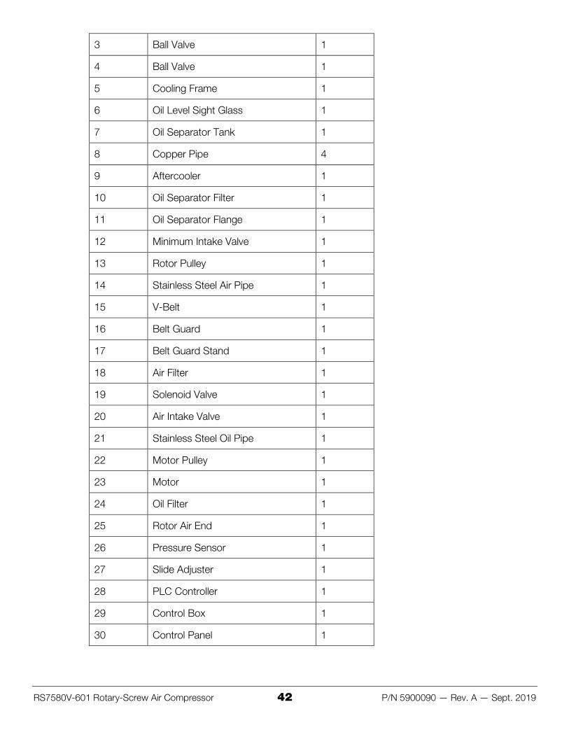
Components
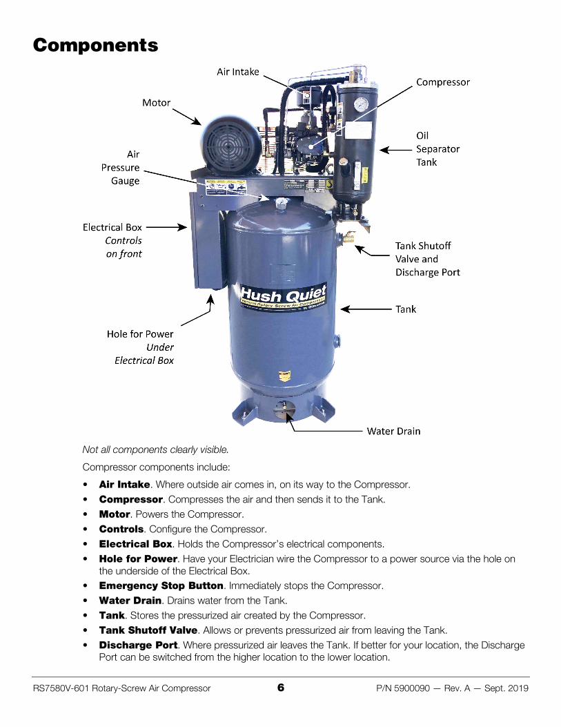
Not all components clearly visible.
Compressor components include:
• Air Intake. Where outside air comes in, on its way to the Compressor. • Compressor. Compresses the air and then sends it to the Tank. • Motor. Powers the Compressor. • Controls. Configure the Compressor. • Electrical Box. Holds the Compressor’s electrical components. • Hole for Power. Have your Electrician wire the Compressor to a power source via the hole on
the underside of the Electrical Box. • Emergency Stop Button. Immediately stops the Compressor. • Water Drain. Drains water from the Tank. • Tank. Stores the pressurized air created by the Compressor. • Tank Shutoff Valve. Allows or prevents pressurized air from leaving the Tank. • Discharge Port. Where pressurized air leaves the Tank. If better for your location, the Discharge
Port can be switched from the higher location to the lower location.
RS7580V-601 Rotary-Screw Air Compressor 7 P/N 5900090 — Rev. A — Sept. 2019
• Pressure Relief Valve. Releases air pressure from the Tank if it exceeds 175 psi. ASME certified. Do not remove or adjust the Valve; if you do, you put people in danger and void the warranty. Do not open the Valve while there is air pressure in the Tank.
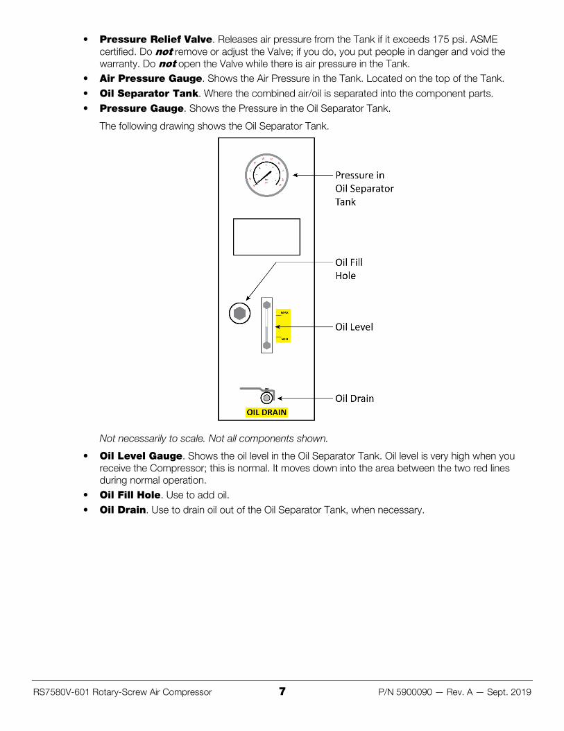
• Air Pressure Gauge. Shows the Air Pressure in the Tank. Located on the top of the Tank. • Oil Separator Tank. Where the combined air/oil is separated into the component parts. • Pressure Gauge. Shows the Pressure in the Oil Separator Tank.
The following drawing shows the Oil Separator Tank.
Not necessarily to scale. Not all components shown.
• Oil Level Gauge. Shows the oil level in the Oil Separator Tank. Oil level is very high when you receive the Compressor; this is normal. It moves down into the area between the two red lines during normal operation.
• Oil Fill Hole. Use to add oil. • Oil Drain. Use to drain oil out of the Oil Separator Tank, when necessary.
RS7580V-601 Rotary-Screw Air Compressor 8 P/N 5900090 — Rev. A — Sept. 2019
Frequently Asked Questions Question: What does an Air Compressor do? Answer: An Air Compressor compresses air, making it into a power source: pressurized air. That pressurized air can then be used to power pneumatic tools and other things.
⚠ DANGER The pressurized air generated by the Compressor is not human breathable when it leaves the Compressor. If you want it to be human breathable, additional equipment is required. Refer to the current version of the Compressed Gas Association (CGA, an ANSI-approved standards developing organization) for information about what is required for human breathable air.
Q: Can the Compressor be installed outside? A: Technically yes, but we advise against it. Air compressors are designed to be installed indoors. If
your Compressor is outside, the intake air will be dirtier (a significant issue), the electrical components will be subject to extra moisture (including water), and all of the components will be subjected to a harsher environment (cold, wind, rain, humidity, and so on). You will need special protections and accommodations for the unit if you install it outside.
Q: What psi/bar does the Compressor provide? A: The maximum pressure is regulated to 175 psi / 12 bar. The automatic turn-on pressure is
120 psi / 8.3 bar, the automatic shut-off pressure is 175 psi / 12 bar.
Q: What cfm does the Compressor provide? A: 25 cfm at 90 psi / 6.2 bar, 21.3 cfm at 175 psi / 12 bar.
Q: What are cfm and psi? A: cfm is the volume (the amount) of air being delivered. psi is the force at which that air is being
delivered. cfm stands for cubic feet per minute, psi stands for pounds per square inch.
Q: What are the motor specifications for the Compressor? A: 7.5 horsepower, 208-240 VAC, 1 phase. Recommended breaker is 80 amps and 6 AWG wire
gauge.
60 Hz: 1,740 rpm 1/min, amps 32.8-30 A, SF amps 38-34.7 A
50 Hz: 1,445 rpm 1/min, amps 34.3-32.63 A, SF amps 34.3-32.63 A
RS7580V-601 Rotary-Screw Air Compressor 9 P/N 5900090 — Rev. A — Sept. 2019
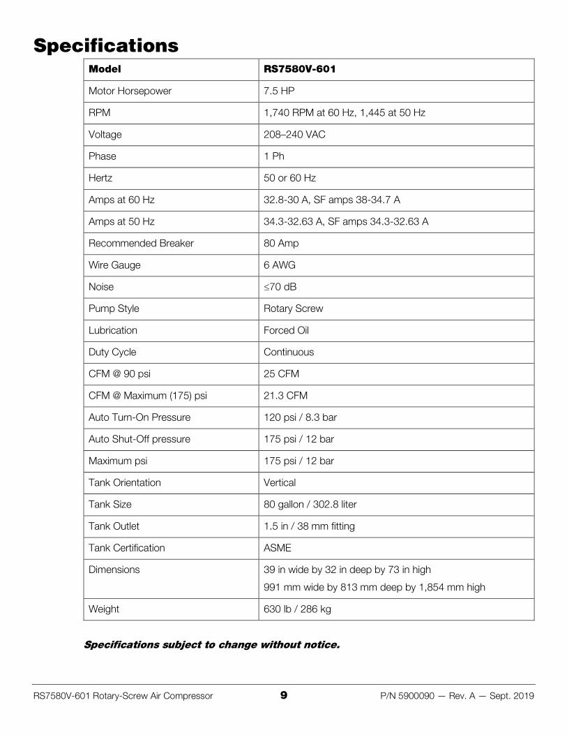
Specifications Model RS7580V-601
Motor Horsepower 7.5 HP
RPM 1,740 RPM at 60 Hz, 1,445 at 50 Hz
Voltage 208–240 VAC
Phase 1 Ph
Hertz 50 or 60 Hz
Amps at 60 Hz 32.8-30 A, SF amps 38-34.7 A
Amps at 50 Hz 34.3-32.63 A, SF amps 34.3-32.63 A
Recommended Breaker 80 Amp
Wire Gauge 6 AWG
Noise ≤70 dB
Pump Style Rotary Screw
Lubrication Forced Oil
Duty Cycle Continuous
CFM @ 90 psi 25 CFM
CFM @ Maximum (175) psi 21.3 CFM
Auto Turn-On Pressure 120 psi / 8.3 bar
Auto Shut-Off pressure 175 psi / 12 bar
Maximum psi 175 psi / 12 bar
Tank Orientation Vertical
Tank Size 80 gallon / 302.8 liter
Tank Outlet 1.5 in / 38 mm fitting
Tank Certification ASME
Dimensions 39 in wide by 32 in deep by 73 in high
991 mm wide by 813 mm deep by 1,854 mm high
Weight 630 lb / 286 kg
Specifications subject to change without notice.
RS7580V-601 Rotary-Screw Air Compressor 10 P/N 5900090 — Rev. A — Sept. 2019
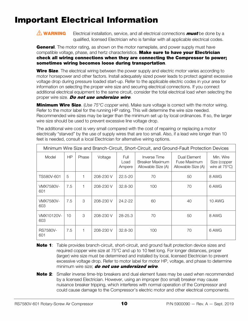
Important Electrical Information ⚠ WARNING Electrical installation, service, and all electrical connections must be done by a
qualified, licensed Electrician who is familiar with all applicable electrical codes.
General. The motor rating, as shown on the motor nameplate, and power supply must have compatible voltage, phase, and hertz characteristics. Make sure to have your Electrician check all wiring connections when they are connecting the Compressor to power; sometimes wiring becomes loose during transportation.
Wire Size. The electrical wiring between the power supply and electric motor varies according to motor horsepower and other factors. Install adequately sized power leads to protect against excessive voltage drop during pressure loaded start-up. Refer to the applicable electric codes in your area for information on selecting the proper wire size and securing electrical connections. If you connect additional electrical equipment to the same circuit, consider the total electrical load when selecting the proper wire size. Do not use undersize wire.
Minimum Wire Size. (Use 75°C copper wire). Make sure voltage is correct with the motor wiring. Refer to the motor label for the running HP rating. This will determine the wire size needed. Recommended wire sizes may be larger than the minimum set up by local ordinances. If so, the larger wire size should be used to prevent excessive line voltage drop.
The additional wire cost is very small compared with the cost of repairing or replacing a motor electrically “starved” by the use of supply wires that are too small. Also, if a lead wire longer than 10 feet is needed, consult a local Electrician for alternative wiring options.
Minimum Wire Size and Branch-Circuit, Short-Circuit, and Ground-Fault Protection Devices
Model HP Phase Voltage Full Load
Ampere
Inverse Time Breaker Maximum Allowable Size (A)
Dual Element Fuse Maximum
Allowable Size (A)
Min. Wire Size (copper wire at 75°C)
TS580V-601 5 1 208-230 V 22.5-20 70 50 8 AWG
VMX7580V-601
7.5 1 208-230 V 32.8-30 100 70 6 AWG
VMX7580V-603
7.5 3 208-230 V 24.2-22 60 40 10 AWG
VMX10120V-603
10 3 208-230 V 28-25.3 70 50 8 AWG
RS7580V-601
7.5 1 208-230 V 32.8-30 100 70 6 AWG
Note 1: Table provides branch-circuit, short-circuit, and ground fault protection device sizes and required copper wire size at 75°C and up to 10 feet long. For longer distances, proper (larger) wire size must be determined and installed by local, licensed Electrician to prevent excessive voltage drop. Refer to motor label for motor HP, voltage, and phase to determine minimum wire size; do not use undersized wire.
Note 2: Smaller inverse time-trip breakers and dual element fuses may be used when recommended by a licensed Electrician. However, using an improper (too small) breaker may cause nuisance breaker tripping, which interferes with normal operation of the Compressor and could cause damage to the Compressor’s electric motor and other electrical components.
RS7580V-601 Rotary-Screw Air Compressor 11 P/N 5900090 — Rev. A — Sept. 2019
Fuses / Circuit Breakers. Refer to applicable local codes to determine the proper fuse or circuit breaker rating required. When selecting fuses, remember the momentary starting current of an electric motor is greater than its full load current. Time delay or “slow-blow” fuses are recommended.
Grounding. In the event of an electrical short circuit, grounding reduces the risk of electric shock by providing an escape wire for the electric current. Ground terminals are identified with a ground symbol and/or the letters “G”, “GR” or “PE” (Potential Earth).
Ground must be established with a grounding wire size according to the voltage and minimum branch circuit requirements printed on the compressor specifications decal. Ensure good bare metal contact at all grounding connection points, and ensure all connections are clean and tight.
⚠ WARNING Improper grounding can result in electrical shock and can cause severe injury or death. This product must be connected to a grounded, metallic, permanent wiring system or an equipment-grounding terminal or lead. All grounding must be performed by a qualified, licensed Electrician and must comply with all applicable electric codes.
RS7580V-601 Rotary-Screw Air Compressor 12 P/N 5900090 — Rev. A — Sept. 2019
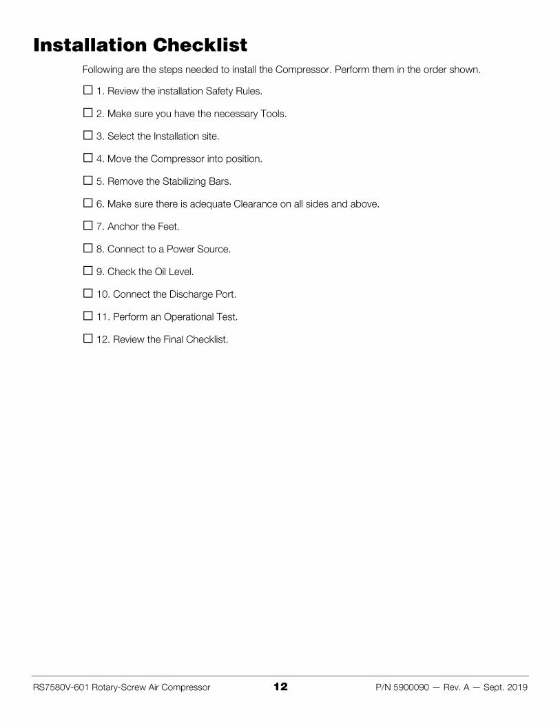
Installation Checklist Following are the steps needed to install the Compressor. Perform them in the order shown.
☐ 1. Review the installation Safety Rules.
☐ 2. Make sure you have the necessary Tools.
☐ 3. Select the Installation site.
☐ 4. Move the Compressor into position.
☐ 5. Remove the Stabilizing Bars.
☐ 6. Make sure there is adequate Clearance on all sides and above.
☐ 7. Anchor the Feet.
☐ 8. Connect to a Power Source.
☐ 9. Check the Oil Level.
☐ 10. Connect the Discharge Port.
☐ 11. Perform an Operational Test.
☐ 12. Review the Final Checklist.
RS7580V-601 Rotary-Screw Air Compressor 13 P/N 5900090 — Rev. A — Sept. 2019
Installation This section describes how to install your Compressor. Perform the steps in the order listed.
⚠ WARNING Use only the factory-supplied parts that came with your unit. If you use parts from a different source, you void your warranty and compromise the safety of everyone who installs or uses the Compressor. If you are missing parts, visit bendpak.com/support or call (800) 253-2363, extension 191.
Safety Rules When installing the Compressor, your safety depends on proper training and thoughtful operation.
⚠ WARNING Do not install this equipment unless you have installation training. Always use proper tools, such as a Forklift, to move heavy components. Do not install the unit without reading and understanding this manual and the safety labels on the unit.
Only fully trained personnel should be involved in installing this equipment. Pay attention at all times. Use appropriate tools and equipment. Stay clear of moving parts.
⚠ WARNING You must wear OSHA-approved (publication 3151) personal protective equipment at all times when installing the Compressor: leather gloves, steel-toed work boots, eye protection, back belts, and hearing protection.
Tools You may need some or all of the following tools:
• Two adjustable wrenches, one pipe wrench • Socket and ratchet set • Medium slot and Philips screwdriver • Forklift • Rotary hammer drill or similar • Masonry bits
RS7580V-601 Rotary-Screw Air Compressor 14 P/N 5900090 — Rev. A — Sept. 2019
Select a Location Keep the following in mind when selecting a location:
• Clearance. You must have adequate space on all sides and above. See Clearance for more information. Make sure the Compressor is at least 3.3 feet / 1 meter from a wall or corner, with at least 3.3 feet / 1 meter of open space above the unit (for good air circulation).
• Floor. Install your Compressor on a flat, dry concrete floor. • Power. You will need a 208–240 VAC power source available near the Compressor. Use a 60
amp or greater fuse and 6 AWG wire. • Operating temperature. The Compressor is designed to be used between temperatures of
41º to 104ºF (5º to 40ºC). • Second floor installs. Do not install the Compressor on a second floor or elevated floor without
first consulting the building architect and getting their permission. • Indoor installation. Your Compressor works best with clean, dry air, which is found indoors. If
you install the Compressor outdoors, the air is wetter and dirtier; outside air must be filtered before it can be used with the Compressor.
• Ventilation. Install the Compressor in a well-ventilated area, away from sources of contamination such as dirt or dust. You do not want the Compressor pulling in the same air that just came out of it; that air is hot and dirty, not suitable for air intake. Installing the Compressor in a dust-filled environment is not acceptable; it will damage the Compressor and it voids your warranty.
⚠ DANGER The pressurized air generated by the Compressor is not human breathable when it leaves the Compressor. If you want it to be human breathable, additional equipment is required. Refer to the current version of the Compressed Gas Association (CGA, an ANSI-approved standards developing organization) for information about what is required for human breathable air.
RS7580V-601 Rotary-Screw Air Compressor 15 P/N 5900090 — Rev. A — Sept. 2019
Moving the Compressor There are two appropriate ways to move the Compressor:
• Move the Pallet the Compressor is on using a Forklift. One way to move your Compressor to the desired location is to use a Forklift from underneath while the Compressor is still on its pallet. Make sure the Compressor is firmly secured to the Pallet before moving it.
• Move the Compressor from Above using the Two Eye Bolts. The Compressor comes with two heavy-duty, silver Eye Bolts, which can be used—together—to lift the Compressor from above. Use great care if you decide to lift the Compressor from above using the Eye Bolts. Make sure the Eye Bolts are securely in place before lifting the Compressor using them.
⚠ WARNING You must use both Eye Bolts; do not lift the Compressor from above using only one of the Eye Bolts.
RS7580V-601 Rotary-Screw Air Compressor 16 P/N 5900090 — Rev. A — Sept. 2019
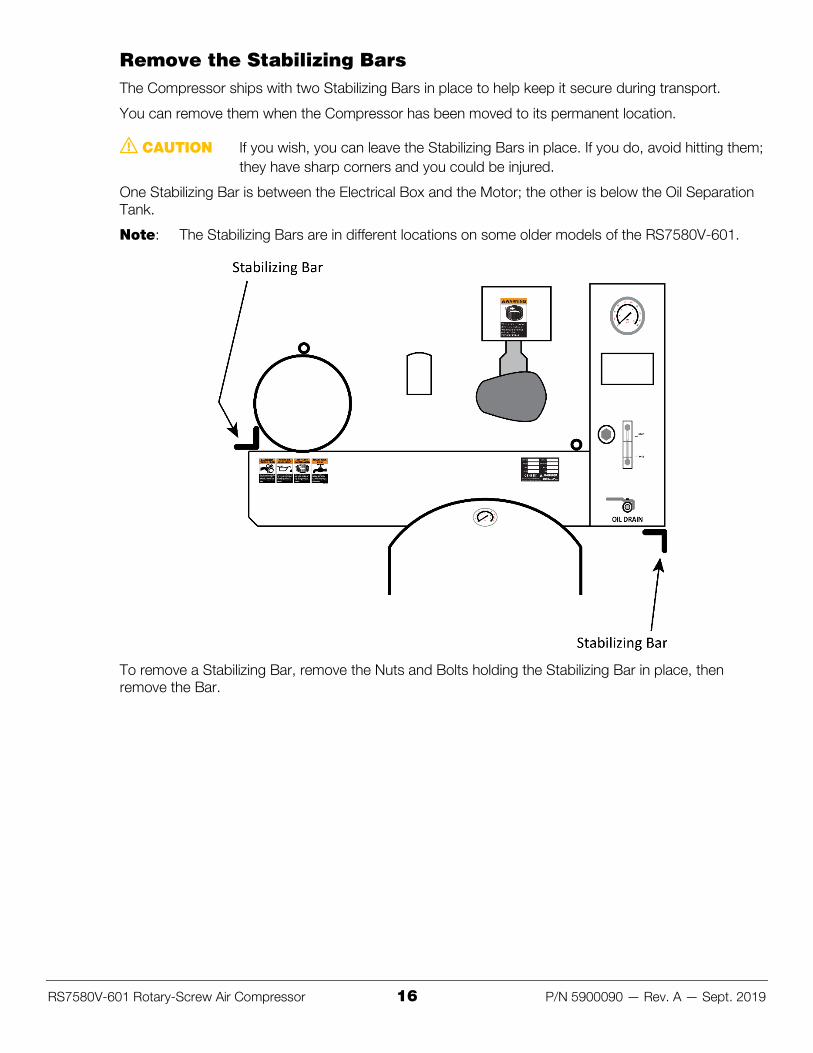
Remove the Stabilizing Bars The Compressor ships with two Stabilizing Bars in place to help keep it secure during transport.
You can remove them when the Compressor has been moved to its permanent location.
⚠ CAUTION If you wish, you can leave the Stabilizing Bars in place. If you do, avoid hitting them; they have sharp corners and you could be injured.
One Stabilizing Bar is between the Electrical Box and the Motor; the other is below the Oil Separation Tank.
Note: The Stabilizing Bars are in different locations on some older models of the RS7580V-601.
To remove a Stabilizing Bar, remove the Nuts and Bolts holding the Stabilizing Bar in place, then remove the Bar.
RS7580V-601 Rotary-Screw Air Compressor 17 P/N 5900090 — Rev. A — Sept. 2019
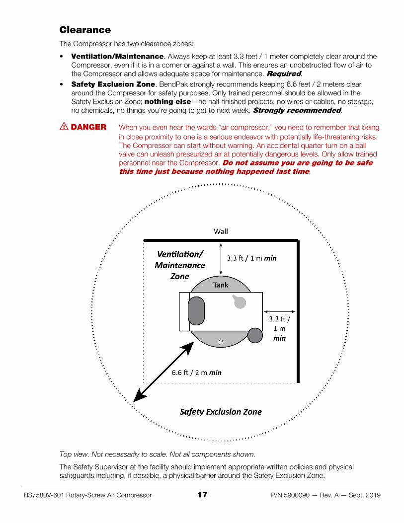
Clearance The Compressor has two clearance zones:
• Ventilation/Maintenance. Always keep at least 3.3 feet / 1 meter completely clear around the Compressor, even if it is in a corner or against a wall. This ensures an unobstructed flow of air to the Compressor and allows adequate space for maintenance. Required.
• Safety Exclusion Zone. BendPak strongly recommends keeping 6.6 feet / 2 meters clear around the Compressor for safety purposes. Only trained personnel should be allowed in the Safety Exclusion Zone; nothing else—no half-finished projects, no wires or cables, no storage, no chemicals, no things you’re going to get to next week. Strongly recommended.
⚠ DANGER When you even hear the words “air compressor,” you need to remember that being in close proximity to one is a serious endeavor with potentially life-threatening risks. The Compressor can start without warning. An accidental quarter turn on a ball valve can unleash pressurized air at potentially dangerous levels. Only allow trained personnel near the Compressor. Do not assume you are going to be safe this time just because nothing happened last time.
Top view. Not necessarily to scale. Not all components shown.
The Safety Supervisor at the facility should implement appropriate written policies and physical safeguards including, if possible, a physical barrier around the Safety Exclusion Zone.
RS7580V-601 Rotary-Screw Air Compressor 18 P/N 5900090 — Rev. A — Sept. 2019
Anchor the Feet If desired, you can anchor each of the four feet on the Compressor. This provides extra stability for the unit. Anchoring the feet is optional; anchor bolts are not provided.
Important: Whether you decide to anchor your Compressor or not, remember to use the supplied Anti-Vibration Pads between the Compressor feet and the ground.
Recommended Anchor Bolt specifications: wedge anchors; 3/8 in wide by 3.5 in deep; torque to 55 pound feet.
To anchor the Compressor feet:
1. Make sure the Compressor is in the desired location.
Once anchor bolts are torqued into position, they are not easily removed. BendPak strongly recommends making sure the Compressor is in the desired location before anchoring it into place.
2. Put the Anti-Vibration Pads under the feet of the Compressor.
3. Using the holes in the feet as guides, drill the holes for the Anchor Bolts through the Anti-Vibration Pads and into the concrete.
Go in straight; do not let the drill wobble.
Use a carbide bit (conforming to ANSI B212.15).
The diameter of the drill bit must be the same as the diameter of the Anchor Bolt. So if you are using a 3/8 inch diameter Anchor Bolt, for example, use a 3/8 inch diameter drill bit.
4. Use a vacuum to thoroughly clean each hole.
If a vacuum is not available, use a wire brush, hand pump, or compressed air.
Do not ream the hole. Do not make the hole any wider than the drill bit made it.
5. Put the washer and nut into place, make sure the top of the nut is flush with the top of the Anchor Bolt, then insert the Anchor Bolt into the hole.
6. Hammer or mallet the Anchor Bolt down into the hole.
Stop hammering when the washer is snug against the top of the foot.
7. Wrench each Nut clockwise to the recommended installation torque, 55 pound feet, using a torque wrench.
Important: Do not use an impact wrench to torque the Anchor Bolts.
Wrenching the nut forces the wedge up, pushing out the expansion sleeve and pressing it tightly against the concrete.
RS7580V-601 Rotary-Screw Air Compressor 19 P/N 5900090 — Rev. A — Sept. 2019
Connect to a Power Source The Compressor must be connected to an appropriate power source.
⚠ DANGER All electrical work must be done by a licensed, certified Electrician in accordance with all applicable local electrical codes. Damage caused by improper electrical installation may void your warranty.
All electrical work must conform to applicable local, state, and federal codes, rules, and regulations, such as state and federal OSHA regulations and electrical codes. The Compressor must be grounded.
Important: BendPak recommends having your Electrician check all wire connections inside the Electrical Box; sometimes they can become loose during transport.
Based on what’s best for your specific location, most customers have their Electrician:
• Wire the Compressor directly into the facility’s electrical system, or • Add a power cord with appropriate plug to the Compressor, which is then plugged in to an
appropriate power source.
The Electrician will need to provide these components; they are not supplied with the Compressor.
There is a hole in the bottom of the Electrical Box (labelled Power In on the inside) specifically for wiring the Compressor to a power source.
Important: The Compressor uses electrical energy and creates pneumatic energy; if your organization has Lockout/Tagout policies, make sure to implement them after connecting the Compressor to a power source.
The Compressor’s motor is 7.5 horsepower, 208-240 VAC, 50 or 60 Hz, 1 phase. BendPak recommends using a 60 Amp breaker and 6 AWG (if the 60 Amp breaker trips frequently, switch to a higher breaker until the tripping stops) . Check the ID plate for additional information.
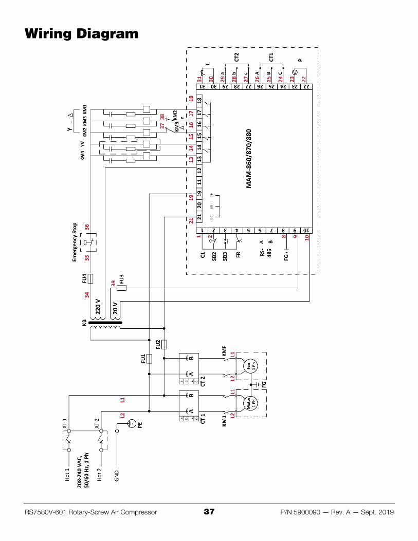
This drawing on the next page uses the United States color codes for the three wires that need to be connected inside the Compressor’s Electrical Box:
• Black: Live • White: Live • Green: Ground
If you are using the Compressor in Europe, the Black – White – Green colors correspond to:
• Brown: Live • Blue: Neutral • Green/Yellow: Ground
Information about color code conventions in other regions and countries is available online.
To connect the Compressor to a power source:
1. Work with the Electrician to decide whether you are going to wire the Compressor into the facility’s electrical system or connect a power cord with appropriate plug.
2. Have your Electrician get the necessary components.
3. Route the wiring through the hole in the bottom of the Electrical Box.
The wiring needs to have three wires, Black-White-Green in the United States.
RS7580V-601 Rotary-Screw Air Compressor 20 P/N 5900090 — Rev. A — Sept. 2019
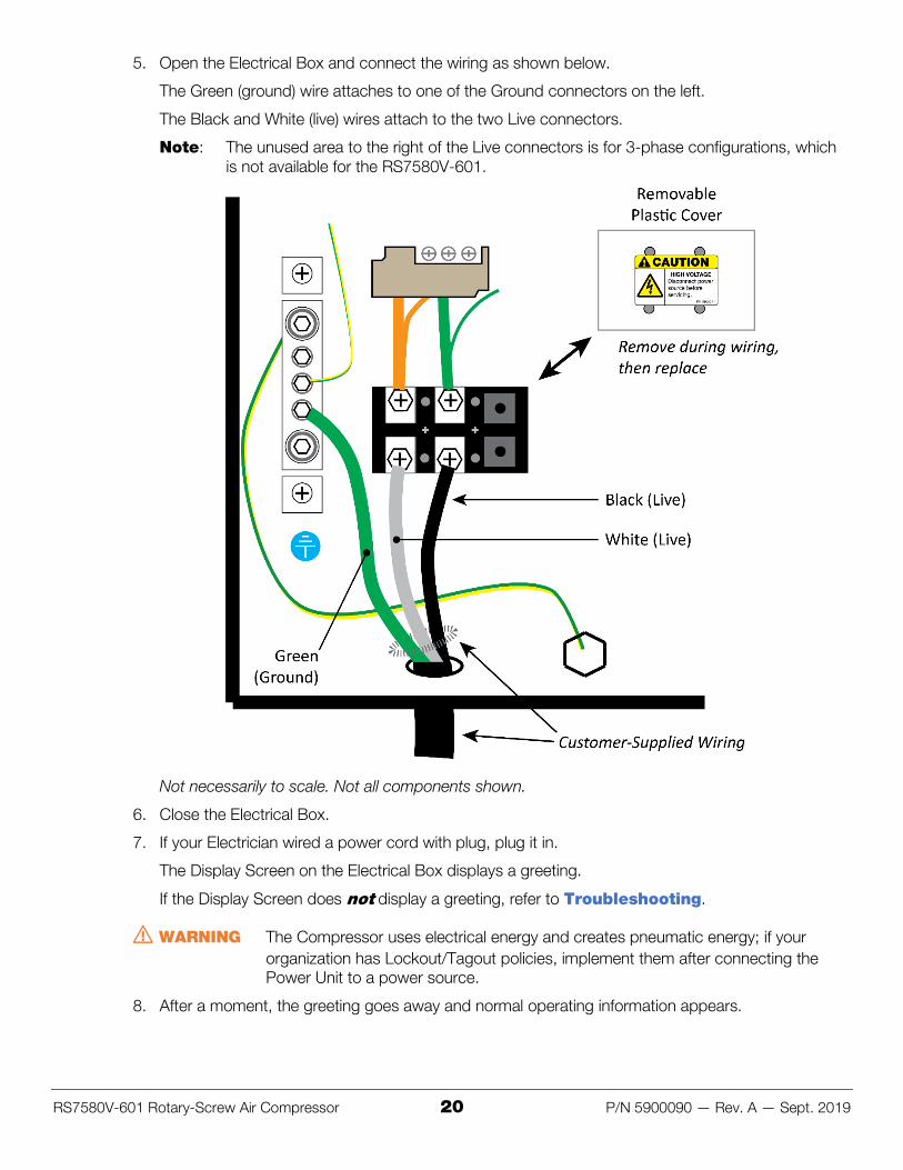
5. Open the Electrical Box and connect the wiring as shown below.
The Green (ground) wire attaches to one of the Ground connectors on the left.
The Black and White (live) wires attach to the two Live connectors.
Note: The unused area to the right of the Live connectors is for 3-phase configurations, which is not available for the RS7580V-601.
Not necessarily to scale. Not all components shown.
6. Close the Electrical Box.
7. If your Electrician wired a power cord with plug, plug it in.
The Display Screen on the Electrical Box displays a greeting.
If the Display Screen does not display a greeting, refer to Troubleshooting.
⚠ WARNING The Compressor uses electrical energy and creates pneumatic energy; if your organization has Lockout/Tagout policies, implement them after connecting the Power Unit to a power source.
8. After a moment, the greeting goes away and normal operating information appears.
RS7580V-601 Rotary-Screw Air Compressor 21 P/N 5900090 — Rev. A — Sept. 2019
Check the Oil Level The Compressor comes filled with oil/lubricant.
The amount of oil must be between the two red lines while the Compressor is running.
Not necessarily to scale. Not all components shown.
Important: When the Compressor is off or has been stopped for over 30 minutes, the oil level will rise; it will be above the top red line; this is normal. This includes when you initially receive the Compressor; the oil level will be above the top red line.
⚠ WARNING Do not overfill or under fill the oil. If you overfill, there could be too much oil in the pressurized air. If you under fill, the Compressor could overheat and be permanently damaged, which voids the warranty.
If you require additional oil, get 46 HT Synthetic Compressor Oil.
Connect the Discharge Port Connect the Tank’s Discharge Port to the facility’s Air Pressure infrastructure.
⚠ WARNING Do not route compressed air through PVC. It could get brittle and then crack or burst, which could cause damage to the facility and injure bystanders. All components of the facility’s Air Pressure infrastructure must have a pressure rating of 200 psi or greater.
If the facility does not already have an Air Pressure infrastructure, you need to create one.
Creating an Air Pressure infrastructure is out of the scope of this document; BendPak recommends consulting with a professional.
To gather information on the subject for yourself, search the Internet for “compressed air system for shop”; you will find products, videos, and articles.
RS7580V-601 Rotary-Screw Air Compressor 22 P/N 5900090 — Rev. A — Sept. 2019
Perform an Operational Test Before putting the Compressor into normal operation, you need to test it.
To perform an Operational Test:
1. Check the area around the Compressor for people or obstructions; move them away if you find any.
2. Check the oil level; add oil if necessary.
The Compressor comes with oil. It should be high on the gauge, as the Compressor is not yet being used.
If you require oil, get 46 HT Synthetic Compressor Oil.
3. Close the Discharge Port using the Ball Valve.
4. Make sure the Compressor is receiving power.
You can do this by checking the Display Screen; if you see text, then the Compressor is receiving power.
5. Press the Start button (I); it is located on the outside of the Electrical Box.
The Compressor starts up.
6. Monitor the gauges to make sure they show operation in normal ranges.
Listen for abnormal noises or vibrations.
Check for any oil leakage.
7. Press the Emergency Stop Button to make sure it is functioning. Turn it to the right to disengage.
⚠ WARNING Use care around the Compressor. Keep all body parts away from the Compressor at all times. It can start up when you do not expect it without any warning.
8. Press the Stop button (O).
There will be a delay, and then the Compressor will shut down.
You can press the Emergency Stop Button at any time to stop the Compressor immediately.
Final Checklist Before Operation Make sure these things have been done before using your Compressor:
• Review the Installation Checklist to make sure all steps have been performed. • Make sure the Motor is getting power. • Check for any oil leaks. • Check to see that all Anti-Vibration Pads and anchor bolts are correctly installed. • Leave the Manual with the owner/operator.
RS7580V-601 Rotary-Screw Air Compressor 23 P/N 5900090 — Rev. A — Sept. 2019
Operation This section describes how to operate your RS7580V-601 Air Compressor.
⚠ DANGER When you even hear the words “air compressor,” you need to remember that being in close proximity to one is a serious endeavor with potentially life-threatening risks. The Compressor can start without warning. An accidental quarter turn on a ball valve can unleash pressurized air at potentially dangerous levels. Only allow trained personnel near the Compressor. Do not assume you are going to be safe this time just because nothing happened last time.
Safety First Before using the Compressor, do the following:
• Check the unit. Check the Compressor for any missing, heavily worn, or damaged parts. Do not operate the Compressor if you find any of these issues; instead, take it out of service, then contact your dealer, email [email protected], visit bendpak.com/support, or call (800) 253-2363, x196.
• Check the area. Check the area around the Compressor for obstructions or people; anything that might impact normal operation of the Compressor. Do not forget to check above the Compressor. If you find an obstruction, move it out of the way. Do not allow anyone within 30 feet of the Compressor while it is connected to a power source.
• Check for safety. Make sure everyone who is going to be walking near the Compressor is aware of its presence and takes appropriate safety measures. Do not allow children to operate or stay near the Compressor. Do not allow anyone under the influence of drugs or alcohol to operate the Compressor. Only trained personnel should ever be allowed inside the Safety Exclusion Zone or be allowed to operate the Compressor.
Anything that could impact the safety of the people in the vicinity of the Compressor must be fully resolved before the Compressor can be used. Only use the unit if it can be used safely.
Quick Start If your Compressor passed the Operational Test and you are willing to use default settings, getting your Compressor up and running can be done quickly.
To quick start your Compressor:
1. Open the Discharge Port using the Ball Valve.
The Discharge Port should already be connected to the facility’s Air Pressure infrastructure. If it is not, connect it, then open the Discharge Port using the Ball Valve.
2. Check the Display Screen to make sure the Compressor is getting power.
3. Check the oil/lubrication level; add oil if necessary.
4. Press the Start button (I).
The Compressor starts up and begins pressurizing air and storing it in the Tank.
5. Check the Display Screen; the third line down should say AUTO LOAD.
The Compressor is up and running using default settings.
RS7580V-601 Rotary-Screw Air Compressor 24 P/N 5900090 — Rev. A — Sept. 2019
Using the Controls Whenever the Compressor has power, the Display Screen shows information.
The Display Screen shows three different kinds of information:
• Startup. The Startup process happens when you connect the Compressor to power. • Normal operation. The Display Screen shows current operating information during normal
operation. • Configuration. The Compressor comes with default settings, some of which can be modified,
and it also keeps track of operational statistics you can view.
The Controls and the three different kinds of information you see on the Display Screen are described in the following sections.
⚠ CAUTION This section describes what you see on the Compressor’s Display Screen during various phases of operation. It assumes the Compressor has been installed correctly, passed its operational test, and is being maintained correctly. If the unit has not passed its operational test, return to Perform an Operational Test and perform the test. If the unit is not being maintained regularly, refer to Maintenance and perform all required maintenance. Neglecting these items can damage the Compressor and void the warranty.
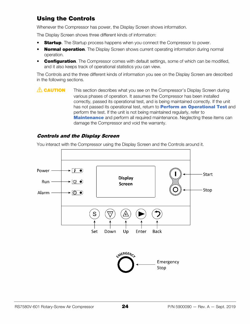
Controls and the Display Screen
You interact with the Compressor using the Display Screen and the Controls around it.
RS7580V-601 Rotary-Screw Air Compressor 25 P/N 5900090 — Rev. A — Sept. 2019
The three Indicators left of the Display Screen are:
• Power. Lightning icon, green background; glows red when the Compressor is receiving power. • Run. Turning fan icon, green background; glows green when the Compressor is running. • Alarm. Exclamation mark icon, red background; glows red when there is an error condition.
The Display Screen is a four-line screen that displays information about, and lets you control, Compressor settings and operation.
The Start and Stop buttons start and stop the Compressor. The Start button starts up the Compressor. The Stop button begins a normal stop procedure; there’s a countdown as the Compressor goes through the steps of a coordinated shutdown. This is compared to an Emergency Stop, where the Compressor stops immediately.
The five Buttons under the Display Screen are:
• Set. Saves configuration changes you have made. • Down. Highlights the next option down or decreases the selected value. • Up. Highlights the next option up or increases the selected value. • Enter. Selects the highlighted option. • Back. Returns to the previous screen.
The Emergency Stop button immediately stops the Compressor. If you press it, it stays in and the Display Screen shows EMERGENCY STOP. Turn the Emergency Stop button to the right to disengage it. The Display Screen changes to NORMAL STOP.
The Display Screen always shows four lines of text:
• The top line shows the air temperature in the Tank. • The second line shows the air pressure in the Tank and how many volts the Compressor is pulling. • The third line shows the current status of the Compressor. • The bottom line shows the communications status of the Compressor. This feature is disabled in
the RS7580V-601, so this line can be safely ignored.
The following shows an example of what you will commonly see on the Display Screen:
Line 1: AIR T: 150°F
Line 2: P:140 PSI 233V
Line 3: AUTO LOAD
Line 4: CO1 LOCAL
Line 3, AUTO LOAD, tells you the Compressor is running at full power and adding air pressure to the Tank, while Line 2 tells you the Tank is nearing full at 140 PSI (assuming a maximum air pressure setting of 175 PSI).
An AUTO UNLOAD state means the Compressor is running at reduced power (but not off) because the Tank is close to full; this reduces the number of start/stop cycles, extending the life of the unit.
The PSI value shown on Line 2 is the same as the pressure shown on the Air Pressure Gauge at the top of the Tank.
Because Line 4 only ever shows communications information, and this feature is disabled, this line will no longer be shown.
RS7580V-601 Rotary-Screw Air Compressor 26 P/N 5900090 — Rev. A — Sept. 2019
Startup
When the Compressor goes from having no power to having power, the Display Screen goes through a Startup process.
On power up, the Display Screen shows:
WELCOME TO USING YOUR SCREW COMPRESSOR
Also, the Power indicator comes on.
After a few seconds, normal operating information appears (similar to the following):
AIR T: 90°F
P:160 PSI 239V
NORMAL STOP
Line 3 will briefly show STARTING (with a countdown), then RUNNING, and finally the normal operating status.
When you see the above information on the Display Screen, the Compressor has started up correctly and is ready for normal operation.
Normal Operation
During normal operation, the Compressor is receiving power and is either building pressure in the Tank or waiting for the Tank pressure to fall below the configured threshold.
⚠ DANGER During normal operation, the Compressor can start operating with no warning. If the Compressor turns on while you are touching it or standing in the wrong place, you could be injured or, in rare cases, killed. Until you are certain that power has been removed from the Compressor and it cannot be reenergized, stay outside the Safety Exclusion Zone. Only trained Operators should ever be inside the Safety Exclusion Zone and only when necessary.
To put the Compressor into normal operation:
1. Check the Display Screen to make sure the Compressor is in a NORMAL STOP state.
If the Compressor was stopped using the Emergency Stop button, it may still be in an EMERGENCY STOP state. If this is the case, turn the Emergency Stop button to the right to reset it; the Compressor will change to a NORMAL STOP state.
If the Display Screen is off, check to make sure the Compressor is getting power.
2. Make sure the Ball Valve on the Discharge Port is set to open.
3. Press the green Start button (I).
The Run indicator comes on, the Compressor motor starts up, and the Compressor starts pressurizing air and storing it in the Tank.
If the Tank is full or close to it, the status of the Compressor (as displayed on the Display Screen) may quickly go to AUTO UNLOAD. If the Tank is empty or not nearly full, the status will go to AUTO LOAD and stay there as the Tank fills.
4. The Compressor is now operating normally.
During normal operation, status will change from AUTO LOAD to AUTO UNLOAD as the Compressor switches between these two states.
RS7580V-601 Rotary-Screw Air Compressor 27 P/N 5900090 — Rev. A — Sept. 2019
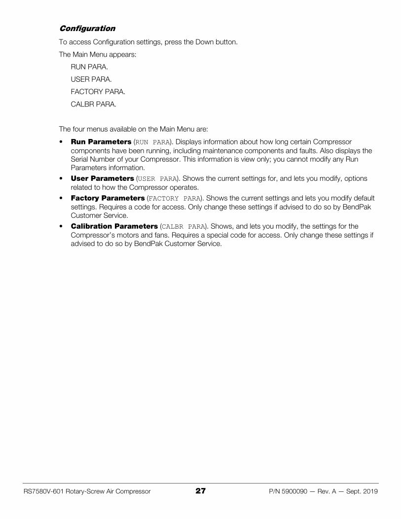
Configuration
To access Configuration settings, press the Down button.
The Main Menu appears:
RUN PARA.
USER PARA.
FACTORY PARA.
CALBR PARA.
The four menus available on the Main Menu are:
• Run Parameters (RUN PARA). Displays information about how long certain Compressor components have been running, including maintenance components and faults. Also displays the Serial Number of your Compressor. This information is view only; you cannot modify any Run Parameters information.
• User Parameters (USER PARA). Shows the current settings for, and lets you modify, options related to how the Compressor operates.
• Factory Parameters (FACTORY PARA). Shows the current settings and lets you modify default settings. Requires a code for access. Only change these settings if advised to do so by BendPak Customer Service.
• Calibration Parameters (CALBR PARA). Shows, and lets you modify, the settings for the Compressor’s motors and fans. Requires a special code for access. Only change these settings if advised to do so by BendPak Customer Service.
RS7580V-601 Rotary-Screw Air Compressor 28 P/N 5900090 — Rev. A — Sept. 2019
Run Parameters
The Run Parameters menu lets you view information about the Compressor. You cannot modify any of these settings.
Run Parameters are:
• MOTOR FAN CUR. Shows the amps being drawn by the motor and the fan. • TOTAL RUN TIME. The total amount of time the Compressor has been running. Total Load Time
is the total amount of time the Compressor has been running in a loading state. • THIS RUN TIME. The amount of time the Compressor has been running in any state in the current
cycle. This Load Time is the amount of time the Compressor has running in a loading state in the current cycle.
• MAINTENANCE PARAMETERS
BEEN USED TIME. The amount of time each item has been in use since original startup or since the most recent maintenance reset.
– OIL FILTER <time>
– O-A FILTER <time>
– AIR FILTER <time>
– LUBE <time>
– GREASE <time>
– BELT <time>
• HISTORY FAULT. Shows the fault history for the Compressor. • SERIAL NUMBER. Shows the Manufactured On date and Serial Number of the Compressor. • THIS FAULT. Displays current faults, if any. Fix the fault to clear the entry. • COM STATUS. Shows RX and TX. This feature is not implemented.
User Parameters
User Parameters give you control over a wide variety of settings. You do not need a code to access the User Parameters settings, but you do need to use the User Pin to modify some of the settings.
User Parameters are:
• P.T. SET:
– LOAD P: xxxx PSI. The PSI at which the Compressor will go into a loading state.
– UNLOAD P: xxxx PSI. The PSI at which the Compressor will go into an unloading state.
– FAN START: xxxx°F. The oil temperature at which the fan comes on.
– FAN STOP: xxxx°F. The oil temperature at which the fan goes off.
RS7580V-601 Rotary-Screw Air Compressor 29 P/N 5900090 — Rev. A — Sept. 2019
• TIMER SET:
– MOTOR START <time in seconds>. Not changeable. The time difference between when the Compressor receives power and the motor starts.
– FAN START <time in seconds>. The temperature at which the Fan starts.
– STAR DELAY <time in seconds>. Not changeable. The time difference between when the motor starts and the Compressor starts running.
– LOAD DELAY <time in seconds>. The time difference between when the Compressor starts running and the unit starts taking in air.
– EMPTY DELAY <time in seconds>. The amount of time the Compressor stays in an Unloaded state before switching to a Normal Stop state.
– STOP DELAY <time in seconds>. The amount of time the Compressor will wait after the Stop button is pressed before shutting down.
– START DELAY <time in seconds>. The amount of time the Compressor will wait after the Start button is pressed before starting up.
• OPERATION MODE
– RUN MODE: LOCAL. Compressor is controlled by local settings (remote mode not supported).
– LOAD MODE: AUTO. Compressor goes from UNLOAD to LOAD automatically, based on settings on the Compressor. MANU not supported.
– COM MODE: MODBUS. Not supported.
– COM ADD: 0001. Not supported.
• SEQ PARA. SET. All of these settings are not supported. • CLR LIFE TIME
– OIL FILTER: <time in hours>. Clears/resets the Oil Filter counter.
– O-A FILTER: <time in hours>. Clears/resets the Oil/Air Filter counter.
– AIR FILTER: <time in hours>. Clears/resets the Air Filter counter.
– LUBE: <time in hours>. Clears/resets the Lube counter.
– GREASE: <time in hours>. Clears/resets the Grease counter.
– BELT: <time in hours>. Clears/resets the Belt counter.
• MAX LIFE TIME
MAX RUN TIME (H)
– OIL FILTER: 0490. Shows when you will be reminded to change the Oil Filter.
– O-A FILTER: 0490. Shows when you will be reminded to change the Oil/Air Filter.
– AIR FILTER: 0490. Shows when you will be reminded to change the Air Filter.
– LUBE: 0490. Shows when you will be reminded to change the Lube.
– GREASE: 0490 . Shows when you will be reminded to change the Grease.
– BELT: 0490 . Shows when you will be reminded to change the Belt.
• LAN. SEL: EN or CN. Select the desired language, English (EN) or Chinese (CN). • NEW USER PIN ****
INPUT CODE: xxxx. Enter the desired new User Pin. The default is 1000.
RS7580V-601 Rotary-Screw Air Compressor 30 P/N 5900090 — Rev. A — Sept. 2019
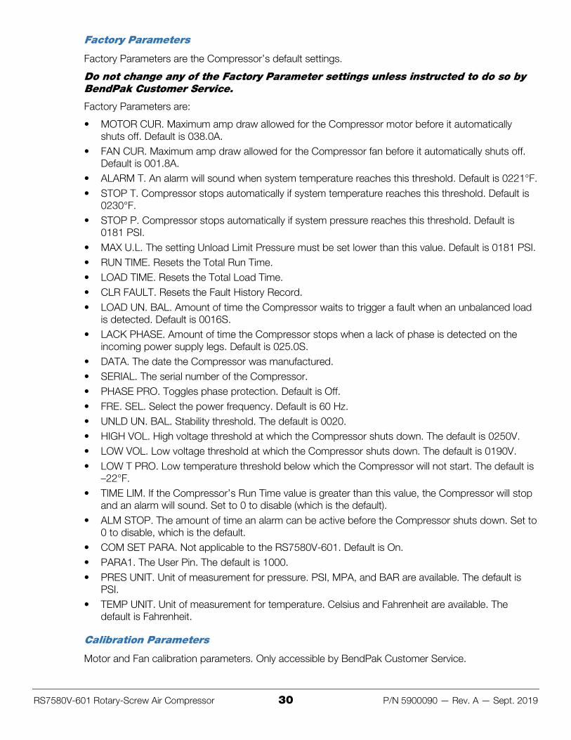
Factory Parameters
Factory Parameters are the Compressor’s default settings.
Do not change any of the Factory Parameter settings unless instructed to do so by BendPak Customer Service.
Factory Parameters are:
• MOTOR CUR. Maximum amp draw allowed for the Compressor motor before it automatically shuts off. Default is 038.0A.
• FAN CUR. Maximum amp draw allowed for the Compressor fan before it automatically shuts off. Default is 001.8A.
• ALARM T. An alarm will sound when system temperature reaches this threshold. Default is 0221°F. • STOP T. Compressor stops automatically if system temperature reaches this threshold. Default is
0230°F. • STOP P. Compressor stops automatically if system pressure reaches this threshold. Default is
0181 PSI. • MAX U.L. The setting Unload Limit Pressure must be set lower than this value. Default is 0181 PSI. • RUN TIME. Resets the Total Run Time. • LOAD TIME. Resets the Total Load Time. • CLR FAULT. Resets the Fault History Record. • LOAD UN. BAL. Amount of time the Compressor waits to trigger a fault when an unbalanced load
is detected. Default is 0016S. • LACK PHASE. Amount of time the Compressor stops when a lack of phase is detected on the
incoming power supply legs. Default is 025.0S. • DATA. The date the Compressor was manufactured. • SERIAL. The serial number of the Compressor. • PHASE PRO. Toggles phase protection. Default is Off. • FRE. SEL. Select the power frequency. Default is 60 Hz. • UNLD UN. BAL. Stability threshold. The default is 0020. • HIGH VOL. High voltage threshold at which the Compressor shuts down. The default is 0250V. • LOW VOL. Low voltage threshold at which the Compressor shuts down. The default is 0190V. • LOW T PRO. Low temperature threshold below which the Compressor will not start. The default is
–22°F. • TIME LIM. If the Compressor’s Run Time value is greater than this value, the Compressor will stop
and an alarm will sound. Set to 0 to disable (which is the default). • ALM STOP. The amount of time an alarm can be active before the Compressor shuts down. Set to
0 to disable, which is the default. • COM SET PARA. Not applicable to the RS7580V-601. Default is On. • PARA1. The User Pin. The default is 1000. • PRES UNIT. Unit of measurement for pressure. PSI, MPA, and BAR are available. The default is
PSI. • TEMP UNIT. Unit of measurement for temperature. Celsius and Fahrenheit are available. The
default is Fahrenheit.
Calibration Parameters
Motor and Fan calibration parameters. Only accessible by BendPak Customer Service.
RS7580V-601 Rotary-Screw Air Compressor 31 P/N 5900090 — Rev. A — Sept. 2019
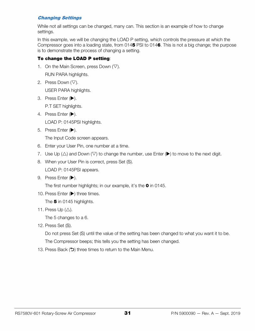
Changing Settings
While not all settings can be changed, many can. This section is an example of how to change settings.
In this example, we will be changing the LOAD P setting, which controls the pressure at which the Compressor goes into a loading state, from 0145 PSI to 0146. This is not a big change; the purpose is to demonstrate the process of changing a setting.
To change the LOAD P setting:
1. On the Main Screen, press Down ().
RUN PARA highlights.
2. Press Down ().
USER PARA highlights.
3. Press Enter ().
P.T SET highlights.
4. Press Enter ().
LOAD P: 0145PSI highlights.
5. Press Enter ().
The Input Code screen appears.
6. Enter your User Pin, one number at a time.
7. Use Up () and Down () to change the number, use Enter () to move to the next digit.
8. When your User Pin is correct, press Set (S).
LOAD P: 0145PSI appears.
9. Press Enter ().
The first number highlights; in our example, it’s the 0 in 0145.
10. Press Enter () three times.
The 5 in 0145 highlights.
11. Press Up ().
The 5 changes to a 6.
12. Press Set (S).
Do not press Set (S) until the value of the setting has been changed to what you want it to be.
The Compressor beeps; this tells you the setting has been changed.
13. Press Back () three times to return to the Main Menu.
RS7580V-601 Rotary-Screw Air Compressor 32 P/N 5900090 — Rev. A — Sept. 2019
Maintenance You must perform maintenance on the Compressor on a regular basis. If you do not perform maintenance on the Compressor per the information in this section, you void your warranty.
⚠ DANGER Before performing any maintenance, make sure the Air Compressor is completely disconnected from power and cannot be re-energized until all maintenance is complete. Secure the plug so that it cannot be accidentally plugged back in. The Compressor uses electrical energy and creates pneumatic energy; if your organization has Lockout/Tagout policies, make sure to implement them.
If you require replacement parts, contact BendPak at (800) 253-2363, extension 191.
Maintenance Shutdown Before performing any Maintenance on the Compressor, you must perform a Maintenance Shutdown. A Maintenance Shutdown is different from a normal shutdown in that you need to make sure the Compressor cannot be re-started until the Maintenance is complete.
⚠ DANGER The Compressor uses electrical energy and creates pneumatic energy; if your organization has Lockout/Tagout policies, make sure to implement them. If the Compressor is re-started while someone is working on it, that person could be injured or killed, and the Compressor could be damaged beyond repair.
To perform a Maintenance Shutdown:
1. Press the Stop button (O) to shut down the Compressor.
2. Let the Compressor cool for a minimum of 60 minutes.
3. Open the Discharge Port and release all of the air pressure in the Tank.
4. When all of the pressure appears to have been released from the Tank, check the Air Pressure Gauge on the top of the Tank to make sure it shows zero (0) and then check the Display Screen to make sure the PSI value on Line 2 also shows zero.
5. Lift up the Pressure Relief Valve using the ring at the top.
6. Remove the Compressor from its power source, either by pulling out the plug or by disconnecting the Compressor from the facility’s electrical system.
7. Take active steps to make sure the Compressor cannot be accidentally re-connected to power until Maintenance is complete.
⚠ DANGER If the Compressor were to restart during Maintenance, anyone in the area could be severely injured or even killed. You must make certain the Compressor cannot be restarted until Maintenance is complete.
If your organization has Lockout/Tagout policies, BendPak strongly recommends locking out the power source during Maintenance.
RS7580V-601 Rotary-Screw Air Compressor 33 P/N 5900090 — Rev. A — Sept. 2019
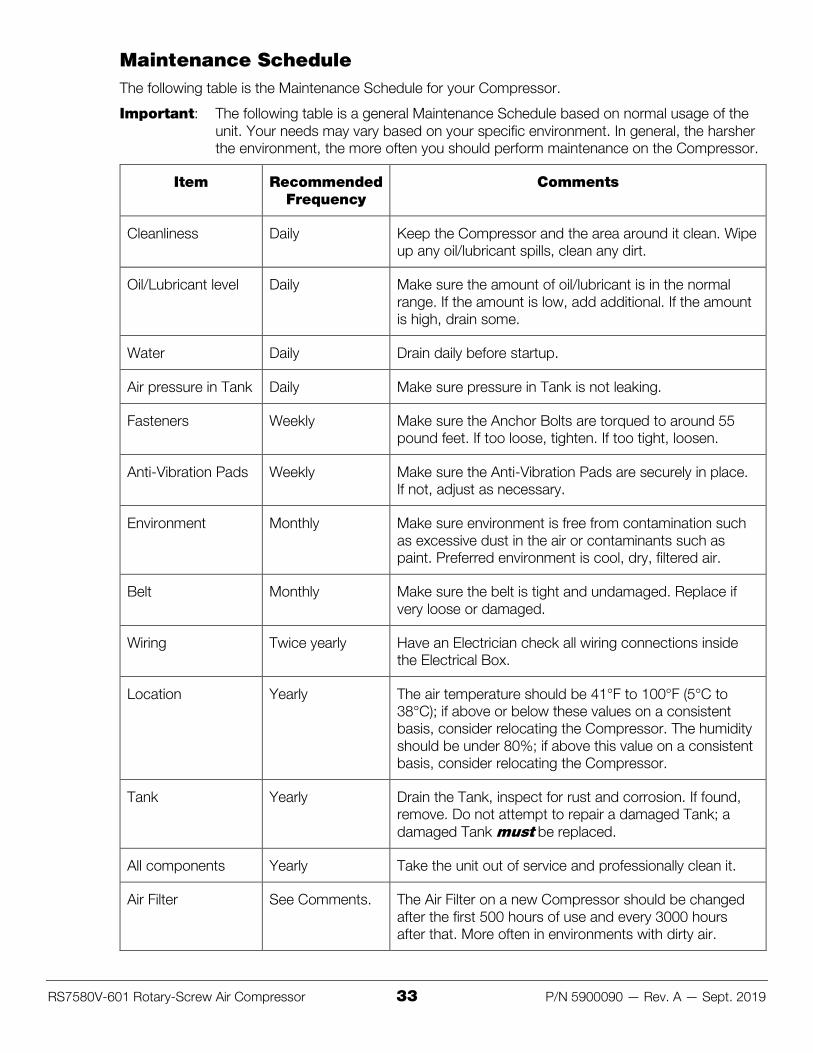
Maintenance Schedule The following table is the Maintenance Schedule for your Compressor.
Important: The following table is a general Maintenance Schedule based on normal usage of the unit. Your needs may vary based on your specific environment. In general, the harsher the environment, the more often you should perform maintenance on the Compressor.
Item Recommended Frequency
Comments
Cleanliness Daily Keep the Compressor and the area around it clean. Wipe up any oil/lubricant spills, clean any dirt.
Oil/Lubricant level Daily Make sure the amount of oil/lubricant is in the normal range. If the amount is low, add additional. If the amount is high, drain some.
Water Daily Drain daily before startup.
Air pressure in Tank Daily Make sure pressure in Tank is not leaking.
Fasteners Weekly Make sure the Anchor Bolts are torqued to around 55 pound feet. If too loose, tighten. If too tight, loosen.
Anti-Vibration Pads Weekly Make sure the Anti-Vibration Pads are securely in place. If not, adjust as necessary.
Environment Monthly Make sure environment is free from contamination such as excessive dust in the air or contaminants such as paint. Preferred environment is cool, dry, filtered air.
Belt Monthly Make sure the belt is tight and undamaged. Replace if very loose or damaged.
Wiring Twice yearly Have an Electrician check all wiring connections inside the Electrical Box.
Location Yearly The air temperature should be 41°F to 100°F (5°C to 38°C); if above or below these values on a consistent basis, consider relocating the Compressor. The humidity should be under 80%; if above this value on a consistent basis, consider relocating the Compressor.
Tank Yearly Drain the Tank, inspect for rust and corrosion. If found, remove. Do not attempt to repair a damaged Tank; a damaged Tank must be replaced.
All components Yearly Take the unit out of service and professionally clean it.
Air Filter See Comments. The Air Filter on a new Compressor should be changed after the first 500 hours of use and every 3000 hours after that. More often in environments with dirty air.
RS7580V-601 Rotary-Screw Air Compressor 34 P/N 5900090 — Rev. A — Sept. 2019
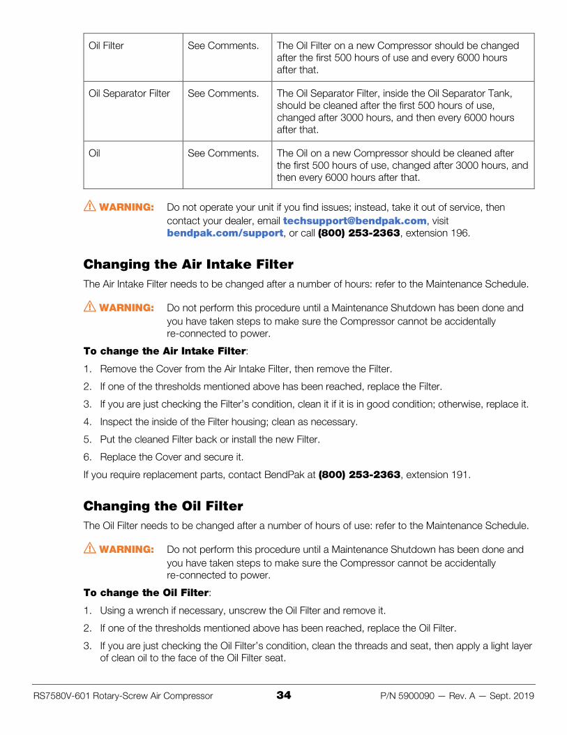
Oil Filter See Comments. The Oil Filter on a new Compressor should be changed after the first 500 hours of use and every 6000 hours after that.
Oil Separator Filter See Comments. The Oil Separator Filter, inside the Oil Separator Tank, should be cleaned after the first 500 hours of use, changed after 3000 hours, and then every 6000 hours after that.
Oil See Comments. The Oil on a new Compressor should be cleaned after the first 500 hours of use, changed after 3000 hours, and then every 6000 hours after that.
⚠ WARNING: Do not operate your unit if you find issues; instead, take it out of service, then contact your dealer, email [email protected], visit bendpak.com/support, or call (800) 253-2363, extension 196.
Changing the Air Intake Filter The Air Intake Filter needs to be changed after a number of hours: refer to the Maintenance Schedule.
⚠ WARNING: Do not perform this procedure until a Maintenance Shutdown has been done and you have taken steps to make sure the Compressor cannot be accidentally re-connected to power.
To change the Air Intake Filter:
1. Remove the Cover from the Air Intake Filter, then remove the Filter.
2. If one of the thresholds mentioned above has been reached, replace the Filter.
3. If you are just checking the Filter’s condition, clean it if it is in good condition; otherwise, replace it.
4. Inspect the inside of the Filter housing; clean as necessary.
5. Put the cleaned Filter back or install the new Filter.
6. Replace the Cover and secure it.
If you require replacement parts, contact BendPak at (800) 253-2363, extension 191.
Changing the Oil Filter The Oil Filter needs to be changed after a number of hours of use: refer to the Maintenance Schedule.
⚠ WARNING: Do not perform this procedure until a Maintenance Shutdown has been done and you have taken steps to make sure the Compressor cannot be accidentally re-connected to power.
To change the Oil Filter:
1. Using a wrench if necessary, unscrew the Oil Filter and remove it.
2. If one of the thresholds mentioned above has been reached, replace the Oil Filter.
3. If you are just checking the Oil Filter’s condition, clean the threads and seat, then apply a light layer of clean oil to the face of the Oil Filter seat.
RS7580V-601 Rotary-Screw Air Compressor 35 P/N 5900090 — Rev. A — Sept. 2019
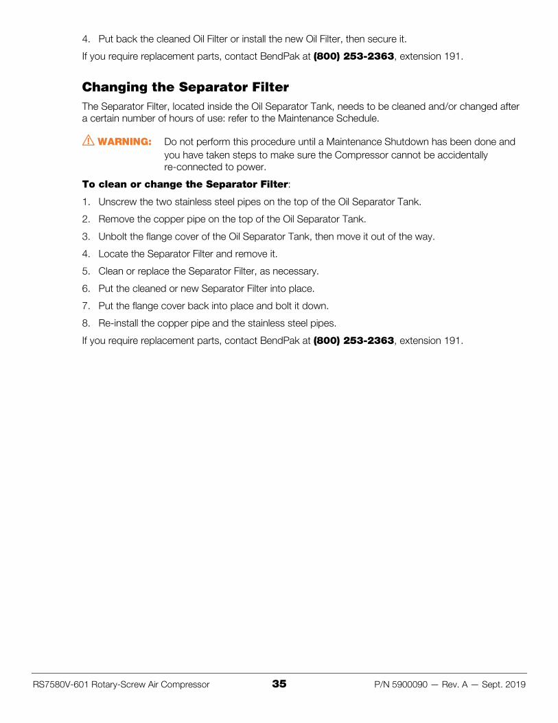
4. Put back the cleaned Oil Filter or install the new Oil Filter, then secure it.
If you require replacement parts, contact BendPak at (800) 253-2363, extension 191.
Changing the Separator Filter The Separator Filter, located inside the Oil Separator Tank, needs to be cleaned and/or changed after a certain number of hours of use: refer to the Maintenance Schedule.
⚠ WARNING: Do not perform this procedure until a Maintenance Shutdown has been done and you have taken steps to make sure the Compressor cannot be accidentally re-connected to power.
To clean or change the Separator Filter:
1. Unscrew the two stainless steel pipes on the top of the Oil Separator Tank.
2. Remove the copper pipe on the top of the Oil Separator Tank.
3. Unbolt the flange cover of the Oil Separator Tank, then move it out of the way.
4. Locate the Separator Filter and remove it.
5. Clean or replace the Separator Filter, as necessary.
6. Put the cleaned or new Separator Filter into place.
7. Put the flange cover back into place and bolt it down.
8. Re-install the copper pipe and the stainless steel pipes.
If you require replacement parts, contact BendPak at (800) 253-2363, extension 191.
RS7580V-601 Rotary-Screw Air Compressor 36 P/N 5900090 — Rev. A — Sept. 2019
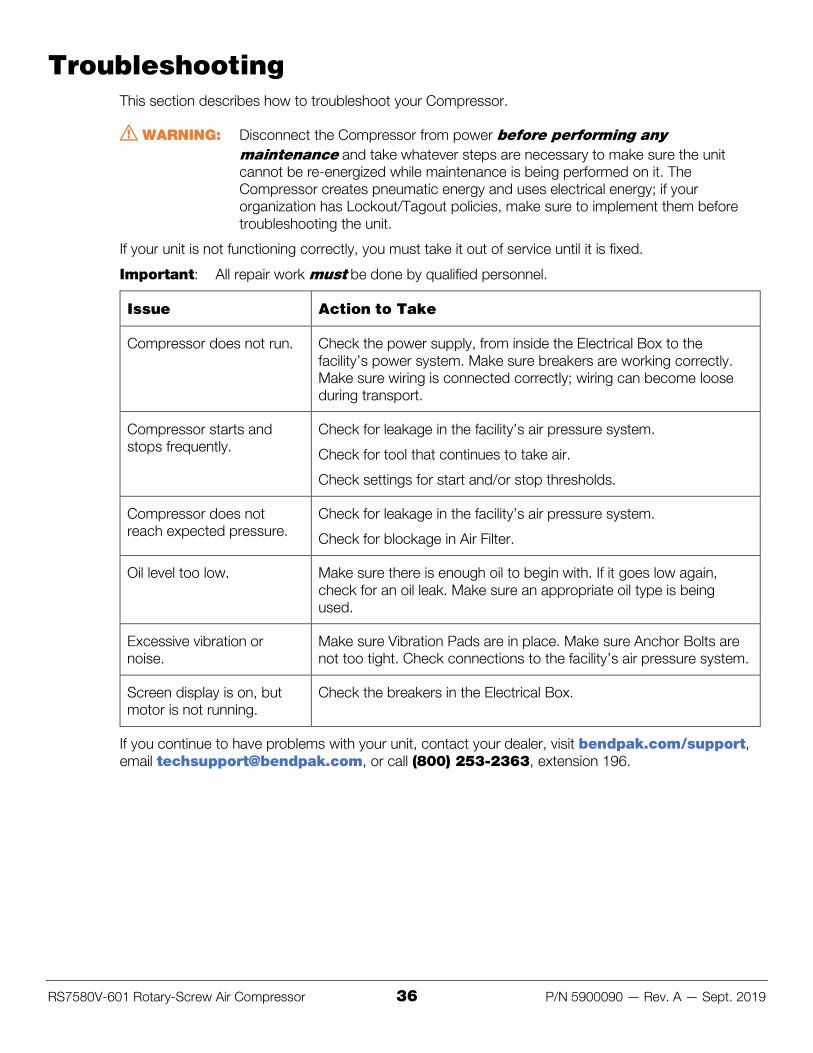
Troubleshooting This section describes how to troubleshoot your Compressor.
⚠ WARNING: Disconnect the Compressor from power before performing any maintenance and take whatever steps are necessary to make sure the unit cannot be re-energized while maintenance is being performed on it. The Compressor creates pneumatic energy and uses electrical energy; if your organization has Lockout/Tagout policies, make sure to implement them before troubleshooting the unit.
If your unit is not functioning correctly, you must take it out of service until it is fixed.
Important: All repair work must be done by qualified personnel.
Issue Action to Take
Compressor does not run. Check the power supply, from inside the Electrical Box to the facility’s power system. Make sure breakers are working correctly. Make sure wiring is connected correctly; wiring can become loose during transport.
Compressor starts and stops frequently.
Check for leakage in the facility’s air pressure system.
Check for tool that continues to take air.
Check settings for start and/or stop thresholds.
Compressor does not reach expected pressure.
Check for leakage in the facility’s air pressure system.
Check for blockage in Air Filter.
Oil level too low. Make sure there is enough oil to begin with. If it goes low again, check for an oil leak. Make sure an appropriate oil type is being used.
Excessive vibration or noise.
Make sure Vibration Pads are in place. Make sure Anchor Bolts are not too tight. Check connections to the facility’s air pressure system.
Screen display is on, but motor is not running.
Check the breakers in the Electrical Box.
If you continue to have problems with your unit, contact your dealer, visit bendpak.com/support, email [email protected], or call (800) 253-2363, extension 196.