60
Data Sheet | Version 03.00 R&S®CMW100 Communications Manufacturing Test Set Specifications R&S®CMW100 – model .K06

Data
She
et |
Vers
ion
03.0
0
R&S®CMW100 Communications Manufacturing Test SetSpecificationsR&S®CMW100 – model .K06
CMW100_K06_dat-sw_en_5214-8348-22_v0300_cover.indd 1 18.10.2018 17:55:12

Version 03.00, October 2018
2 Rohde & Schwarz R&S®CMW100 Communications Manufacturing Test Set
CONTENTS Definitions ....................................................................................................................................................................... 4
General technical specifications ................................................................................................................................... 5
RF generator ..................................................................................................................................................................................... 6
RF analyzer ....................................................................................................................................................................................... 8
Timebase ........................................................................................................................................................................................ 11
GSM specifications – mobile station test ................................................................................................................... 12
GSM RF generator .......................................................................................................................................................................... 12
GSM RF analyzer (R&S®CMW-KM200 option) and GSM EDGE Evolution A analyzer (R&S®CMW-KM201 option) ......................... 13
NB-IoT specifications – mobile station test ................................................................................................................ 15
NB-IoT RF generator ....................................................................................................................................................................... 15
NB-IoT HD-FDD RF analyzer (R&S®CMW-KM300 option) ............................................................................................................... 15
WCDMA specifications – mobile station (UE) test ..................................................................................................... 17
WCDMA RF generator ..................................................................................................................................................................... 17
WCDMA RF analyzer (R&S®CMW-KM400, R&S®CMW-KM401, R&S®CMW-KM403 options) ......................................................... 18
WCDMA specifications – small cell test ...................................................................................................................... 21
WCDMA RF analyzer (R&S®CMW-KN400) ...................................................................................................................................... 21
LTE specifications – mobile station test ..................................................................................................................... 23
LTE FDD RF analyzer (R&S®CMW-KM500 option) .......................................................................................................................... 24
LTE TDD RF analyzer (R&S®CMW-KM550 option) .......................................................................................................................... 26
LTE C-V2X RF analyzer (R&S®CMW-KM570 option)....................................................................................................................... 27
LTE specifications – small cell test ............................................................................................................................. 29
LTE FDD eNodeB RF analyzer (R&S®CMW-KN500 option) ............................................................................................................ 29
LTE TDD eNodeB RF analyzer (R&S®CMW-KN550 option) ............................................................................................................ 31
Bluetooth® specifications ............................................................................................................................................. 33
Bluetooth® RF generator .................................................................................................................................................................. 33
Bluetooth® RF analyzer (R&S®CMW-KM610 option) ........................................................................................................................ 33
Bluetooth® RF analyzer (R&S®CMW-KM611 option) ........................................................................................................................ 35
Bluetooth® RF analyzer (R&S®CMW-KM721 option) ........................................................................................................................ 36
GPS specifications ........................................................................................................................................................ 38
GPS RF generator ........................................................................................................................................................................... 38
DVB specifications ........................................................................................................................................................ 38
DVB RF generator ........................................................................................................................................................................... 38
FM STEREO RADIO specifications .............................................................................................................................. 38
FM STEREO RADIO generator ....................................................................................................................................................... 38
WLAN specifications .................................................................................................................................................... 39
WLAN RF generator ........................................................................................................................................................................ 39
WLAN OFDM RF analyzer ............................................................................................................................................................... 40
WLAN DSSS RF analyzer ............................................................................................................................................................... 42
Version 03.00, October 2018
Rohde & Schwarz R&S®CMW100 Communications Manufacturing Test Set 3
LR-WPAN specifications .............................................................................................................................................. 44
LR-WPAN RF generator .................................................................................................................................................................. 44
LR-WPAN RF analyzer (R&S®CMW-KM680 option) ........................................................................................................................ 44
TD-SCDMA specifications – mobile station (UE) test ................................................................................................ 45
TD-SCDMA RF generator ................................................................................................................................................................ 45
TD-SCDMA RF analyzer (R&S®CMW-KM750 option) ...................................................................................................................... 45
CDMA2000® 1xRTT specifications – mobile station test ........................................................................................... 48
CDMA2000® 1xRTT RF generator ................................................................................................................................................... 48
CDMA2000® RF analyzer (R&S®CMW-KM800 option)..................................................................................................................... 49
CDMA2000® 1xEV-DO specifications – access terminal test .................................................................................... 51
CDMA2000® 1xEV-DO RF generator ............................................................................................................................................... 51
CDMA2000® 1xEV-DO RF analyzer (R&S®CMW-KM880 option) ..................................................................................................... 51
NR specifications – mobile station test ...................................................................................................................... 54
NR sub 6G RF analyzer (R&S®CMW-KM6000 option) ..................................................................................................................... 54
General data .................................................................................................................................................................. 56
Accessories delivered with R&S®CMW-PS16 (1210.7629.03) .................................................................................... 57
External Rohde & Schwarz AC adapter (1210.7812.00) .................................................................................................................. 57
USB 3.0 cable ................................................................................................................................................................................. 57
Ordering information .................................................................................................................................................... 58
R&S®CMW100 communications manufacturing test set ................................................................................................................... 58
Recommended accessories ............................................................................................................................................................. 58
Computer requirements ................................................................................................................................................................... 58
Service options ................................................................................................................................................................................ 59
Data valid for the R&S®CMW100 model K06 unless otherwise stated.
Data sheet values for frequencies above 4000 MHz are only available with the R&S®CMW-K046 option.
Version 03.00, October 2018
4 Rohde & Schwarz R&S®CMW100 Communications Manufacturing Test Set
Definitions General
Product data applies under the following conditions:
Three hours storage at ambient temperature followed by 30 minutes warm-up operation
Specified environmental conditions met
Based on a 24-month calibration interval unless otherwise stated
Recommended calibration interval adhered to
Internal path correction (IPC) adjustment performed
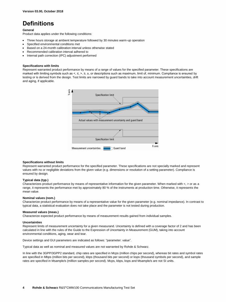
Specifications with limits
Represent warranted product performance by means of a range of values for the specified parameter. These specifications are
marked with limiting symbols such as <, ≤, >, ≥, ±, or descriptions such as maximum, limit of, minimum. Compliance is ensured by
testing or is derived from the design. Test limits are narrowed by guard bands to take into account measurement uncertainties, drift
and aging, if applicable.
Specifications without limits
Represent warranted product performance for the specified parameter. These specifications are not specially marked and represent
values with no or negligible deviations from the given value (e.g. dimensions or resolution of a setting parameter). Compliance is
ensured by design.
Typical data (typ.)
Characterizes product performance by means of representative information for the given parameter. When marked with <, > or as a
range, it represents the performance met by approximately 80 % of the instruments at production time. Otherwise, it represents the
mean value.
Nominal values (nom.)
Characterize product performance by means of a representative value for the given parameter (e.g. nominal impedance). In contrast to
typical data, a statistical evaluation does not take place and the parameter is not tested during production.
Measured values (meas.)
Characterize expected product performance by means of measurement results gained from individual samples.
Uncertainties
Represent limits of measurement uncertainty for a given measurand. Uncertainty is defined with a coverage factor of 2 and has been
calculated in line with the rules of the Guide to the Expression of Uncertainty in Measurement (GUM), taking into account
environmental conditions, aging, wear and tear.
Device settings and GUI parameters are indicated as follows: “parameter: value”.
Typical data as well as nominal and measured values are not warranted by Rohde & Schwarz.
In line with the 3GPP/3GPP2 standard, chip rates are specified in Mcps (million chips per second), whereas bit rates and symbol rates
are specified in Mbps (million bits per second), kbps (thousand bits per second) or ksps (thousand symbols per second), and sample
rates are specified in Msample/s (million samples per second). Mcps, kbps, ksps and Msample/s are not SI units.
Version 03.00, October 2018
Rohde & Schwarz R&S®CMW100 Communications Manufacturing Test Set 5
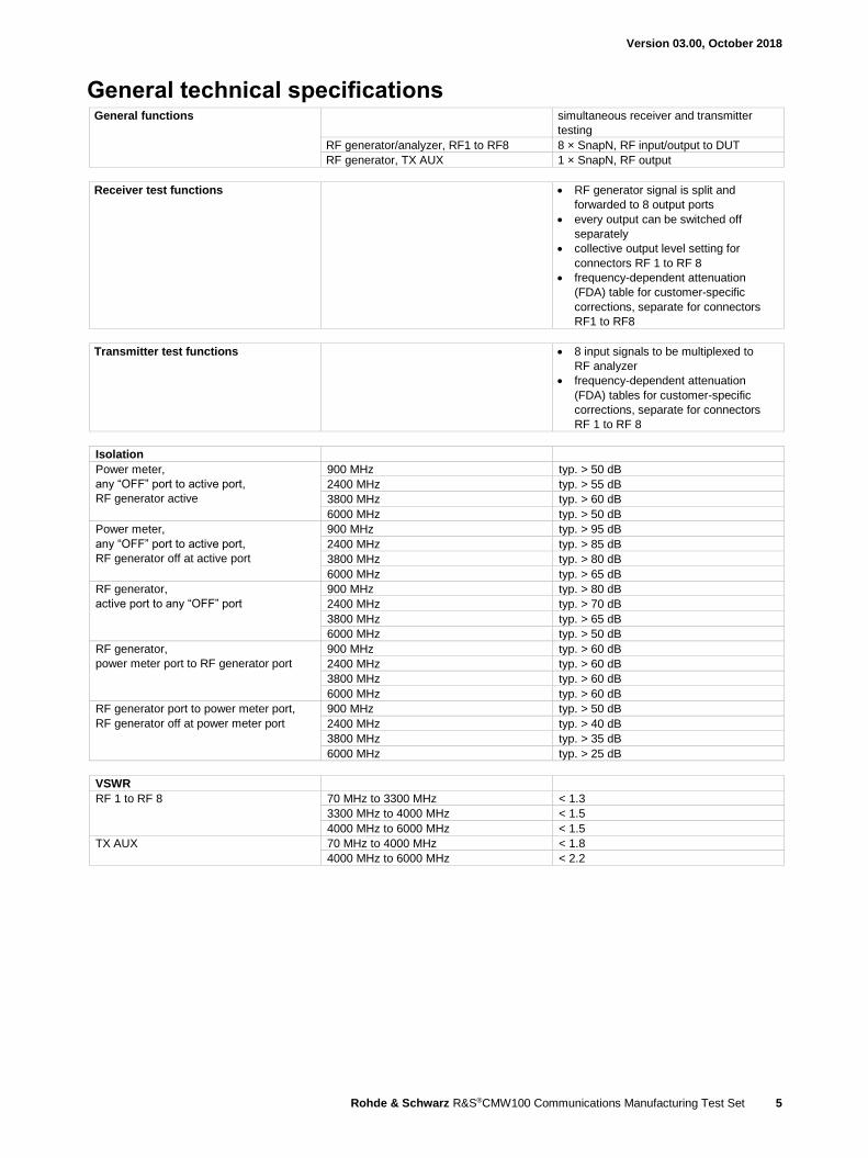
General technical specifications General functions simultaneous receiver and transmitter
testing
RF generator/analyzer, RF1 to RF8 8 × SnapN, RF input/output to DUT
RF generator, TX AUX 1 × SnapN, RF output
Receiver test functions RF generator signal is split and
forwarded to 8 output ports
every output can be switched off
separately
collective output level setting for
connectors RF 1 to RF 8
frequency-dependent attenuation
(FDA) table for customer-specific
corrections, separate for connectors
RF1 to RF8
Transmitter test functions 8 input signals to be multiplexed to
RF analyzer
frequency-dependent attenuation
(FDA) tables for customer-specific
corrections, separate for connectors
RF 1 to RF 8
Isolation
Power meter,
any “OFF” port to active port,
RF generator active
900 MHz typ. > 50 dB
2400 MHz typ. > 55 dB
3800 MHz typ. > 60 dB
6000 MHz typ. > 50 dB
Power meter,
any “OFF” port to active port,
RF generator off at active port
900 MHz typ. > 95 dB
2400 MHz typ. > 85 dB
3800 MHz typ. > 80 dB
6000 MHz typ. > 65 dB
RF generator,
active port to any “OFF” port
900 MHz typ. > 80 dB
2400 MHz typ. > 70 dB
3800 MHz typ. > 65 dB
6000 MHz typ. > 50 dB
RF generator,
power meter port to RF generator port
900 MHz typ. > 60 dB
2400 MHz typ. > 60 dB
3800 MHz typ. > 60 dB
6000 MHz typ. > 60 dB
RF generator port to power meter port,
RF generator off at power meter port
900 MHz typ. > 50 dB
2400 MHz typ. > 40 dB
3800 MHz typ. > 35 dB
6000 MHz typ. > 25 dB
VSWR
RF 1 to RF 8 70 MHz to 3300 MHz < 1.3
3300 MHz to 4000 MHz < 1.5
4000 MHz to 6000 MHz < 1.5
TX AUX 70 MHz to 4000 MHz < 1.8
4000 MHz to 6000 MHz < 2.2

Version 03.00, October 2018
6 Rohde & Schwarz R&S®CMW100 Communications Manufacturing Test Set
RF generator Frequency range 70 MHz to 4000 MHz,
up to 6000 MHz with the R&S®CMW-K046
option
Frequency resolution 0.1 Hz
Frequency uncertainty same as timebase + frequency resolution
Output level range
RF 1 to RF 8 70 MHz to 400 MHz
continuous wave (CW) –130 dBm to –8 dBm
peak envelope power (PEP) up to –8 dBm
overranging (PEP) up to –3 dBm
400 MHz to 4000 MHz
continuous wave (CW) –130 dBm to –8 dBm
peak envelope power (PEP) up to –8 dBm
overranging (PEP) up to –3 dBm
4000 MHz to 6000 MHz
continuous wave (CW) –120 dBm to –15 dBm
peak envelope power (PEP) up to –15 dBm
overranging (PEP) up to –10 dBm
TX AUX 70 MHz to 400 MHz
continuous wave (CW) – 80 dBm to 8 dBm
peak envelope power (PEP) – 80 dBm to 8 dBm
overranging (PEP) – 80 dBm to 13 dBm
400 MHz to 4000 MHz
continuous wave (CW) – 80 dBm to 8 dBm
peak envelope power (PEP) – 80 dBm to 8 dBm
overranging (PEP) – 80 dBm to 13 dBm
4000 MHz to 6000 MHz
continuous wave (CW) –80 dBm to 8 dBm
peak envelope power (PEP) – 80 dBm to 8 dBm
overranging (PEP) – 80 dBm to 13 dBm
Output level uncertainty in temperature range +20 °C to +30 °C 1
RF 1 to RF 8 output level > –120 dBm
70 MHz to 400 MHz < 1.2 dB 2
400 MHz to 2700 MHz < 0.6 dB 2
2700 MHz to 4000 MHz < 1.2 dB 2
4000 MHz to 6000 MHz < 1.2 dB 2
TX AUX output level > –80 dBm
70 MHz to 400 MHz < 1.6 dB 2
400 MHz to 2700 MHz < 0.8 dB 2
2700 MHz to 4000 MHz < 1.6 dB 2
4000 MHz to 6000 MHz < 1.6 dB 2
Output level uncertainty in temperature range +5 °C to +45 °C
RF 1 to RF 8 output level > –120 dBm
70 MHz to 400 MHz < 2.0 dB 2
400 MHz to 2700 MHz < 1.0 dB 2
2700 MHz to 4000 MHz < 2.0 dB 2
4000 MHz to 6000 MHz < 2.0 dB 2
TX AUX output level > –80 dBm
70 MHz to 400 MHz < 2.0 dB 2
400 MHz to 2700 MHz < 1.2 dB 2
2700 MHz to 4000 MHz < 2.0 dB 2
4000 MHz to 6000 MHz < 2.0 dB 2
Output level imbalance difference between RF1 to RF8 typ. < 0.6 dB
1 Relevant is the internal unit temperature, influenced by natural or forced convection.
2 Valid for a 12-month calibration interval.

Version 03.00, October 2018
Rohde & Schwarz R&S®CMW100 Communications Manufacturing Test Set 7
Frequency-dependent attenuation
(FDA) setting range
–30 dB to 0 dB
Max. FDA setting range for specified output level uncertainty –10 dB to 0 dB
Output level linearity with fixed
RF output attenuator setting
in temperature range +20 °C to +30 °C 3,
GPRF generator list mode,
level range 0 dB to –30 dB
RF 1 to RF 8 no overranging < 0.2 dB, typ. < 0.1 dB
Output level resolution 0.01 dB
Output level settling time to within 0.1 dB < 50 µs 4
Output level repeatability typical values after 1 h warm-up time,
always returning to same level and
frequency, no temperature change,
insignificant time change
output level ≥ –80 dBm < 0.01 dB
output level < –80 dBm < 0.05 dB
Attenuation of second harmonic
RF 1 to RF 8 70 MHz to 6000 MHz, P < –10 dBm > 30 dB
TX AUX 70 MHz to 6000 MHz, P < 0 dBm > 30 dB
Attenuation of third harmonic
RF 1 to RF 8 70 MHz to 6000 MHz, P < –10 dBm > 40 dB
TX AUX 70 MHz to 6000 MHz, P < 0 dBm > 40 dB
Attenuation of nonharmonics > 5 kHz offset from carrier,
for output level > –40 dBm,
for full-scale CW signal
400 MHz to 3300 MHz,
except fnonharmonic = 3800 MHz – fcarrier,
except fnonharmonic = abs(3800 MHz – 2 ×
fcarrier),
except fcarrier = (899 to 901) MHz +
n × 800 MHz with n = 1, 2, 3, 4, 5, 6, 7,
except fnonharmonic = 350 MHz +
n × 50 MHz with n = 1 to 12
> 60 dB
3300 MHz to 3600 MHz > 25 dB
3600 MHz to 6000 MHz,
except fnonharmonic = 2 × fcarrier –
6400 MHz
> 40 dB
Phase noise single sideband, 70 MHz to 3300 MHz
Carrier offset ≥ 1 MHz < –120 dBc, 1 Hz
Phase noise single sideband, 3300 MHz to 6000 MHz
Carrier offset ≥ 1 MHz < –117 dBc, 1 Hz
Signal-to-noise ratio 70 MHz to 6000 MHz
RF 1 to RF 8 5 MHz offset from carrier,
for output level > –30 dBm
> 90 dB, typ. > 98 dB, 1 kHz
(> 120 dB, typ. > 128 dB, 1 Hz)
Modulation source: arbitrary waveform generator (ARB)
Memory size 4.096 Gbyte
Word length I 16 bit
Q 16 bit
Sample length with 4-bit marker up to 800 Msample
Sample rate minimum 400 Hz
maximum 200 MHz
Maximum possible RF bandwidth depends on arbitrary waveform file 160 MHz
3 Relevant is the internal unit temperature, influenced by natural or forced convection.
4 When using list mode.

Version 03.00, October 2018
8 Rohde & Schwarz R&S®CMW100 Communications Manufacturing Test Set
RF analyzer Inherent spurious response without input signal, 150 MHz to 6000
MHz,
except n × 500 MHz with n = 5 to 12,
except 100 MHz + n × 50 MHz
with n = 1 to 62
expected nominal power setting
≤ –10 dBm
< –100 dBm
expected nominal power setting
> –10 dBm
< –90 dB below expected nominal power
setting
Spurious response for full-scale single-tone input signal
150 MHz to 3800 MHz,
except fin = 2215.5 MHz and
4425 MHz,
except fin = 2212.5 MHz + fselected
< –55 dB
3800 MHz to 4200 MHz,
except fin = 7200 MHz – fselected,
except fin = 7200 MHz – 0.5 × fselected
< –40 dB
4200 MHz to 6000 MHz,
except fin = 7200 MHz – 0.5 × fselected
< –40 dB
Harmonic response second harmonic
RF 1 to RF 8 fin = 150 MHz to 3000 MHz,
fselected = 300 MHz to 6000 MHz
< –30 dB
Harmonic response third harmonic
RF 1 to RF 8 fin = 150 MHz to 2000 MHz,
fselected = 450 MHz to 6000 MHz
< –50 dB
Phase noise single sideband, 150 MHz to 3800 MHz
Carrier offset ≥ 1 MHz < –120 dBc, 1 Hz
Phase noise single sideband, 3800 MHz to 6000 MHz
Carrier offset ≥ 1 MHz < –117 dBc, 1 Hz
Trigger
Trigger sources GPRF: free run
GPRF: IF power
GPRF: Gen
Power meter
Frequency range 150 MHz to 4000 MHz,
up to 6000 MHz with the R&S®CMW-K046
option
Frequency resolution 0.1 Hz
Resolution bandwidths Gaussian, 1 kHz to 10 MHz, in 1/3/5 steps,
bandpass, 1 kHz to 30 MHz,
in 1/3/5 steps, RRC, α = 0.1,
3.84 MHz, RRC, α = 0.22, WCDMA filter,
1.2288 MHz, CDMA filter
Expected nominal power setting range for ADC full scale
RF 1 to RF 8 150 MHz to 3800 MHz –47 dBm to +42 dBm 5
3800 MHz to 6000 MHz –37 dBm to +42 dBm 5
5 The maximum permissible continuous power is +34 dBm due to thermal limits.
Version 03.00, October 2018
Rohde & Schwarz R&S®CMW100 Communications Manufacturing Test Set 9
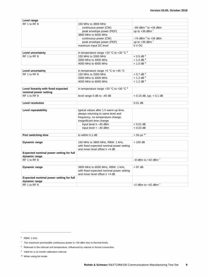
Level range
RF 1 to RF 8 150 MHz to 3800 MHz
continuous power (CW) –84 dBm 6 to +34 dBm
peak envelope power (PEP) up to +36 dBm 7
3800 MHz to 6000 MHz
continuous power (CW) –74 dBm 6 to +34 dBm
peak envelope power (PEP) up to +36 dBm 7
maximum input DC level 0 V DC
Level uncertainty in temperature range +20 °C to +30 °C 8
RF 1 to RF 8 150 MHz to 3300 MHz < 0.5 dB 9
3300 MHz to 4000 MHz < 1.0 dB 9
4000 MHz to 6000 MHz < 1.0 dB 9
Level uncertainty in temperature range +5 °C to +45 °C
RF 1 to RF 8 150 MHz to 3300 MHz < 0.7 dB 9
3300 MHz to 4000 MHz < 1.2 dB 9
4000 MHz to 6000 MHz < 1.2 dB 9
Level linearity with fixed expected
nominal power setting
in temperature range +20 °C to +30 °C 8
RF 1 to RF 8 level range 0 dB to –40 dB < 0.15 dB, typ. < 0.1 dB
Level resolution 0.01 dB
Level repeatability typical values after 1 h warm-up time,
always returning to same level and
frequency, no temperature change,
insignificant time change
input level ≥ –40 dBm < 0.01 dB
input level < –40 dBm < 0.03 dB
Port switching time to within 0.1 dB < 50 µs 10
Dynamic range 150 MHz to 3800 MHz, RBW: 1 kHz,
with fixed expected nominal power setting
and mixer level offset ≥ +4 dB
> 100 dB
Expected nominal power setting for full
dynamic range
RF 1 to RF 8 –8 dBm to +42 dBm 7
Dynamic range 3800 MHz to 6000 MHz, RBW: 1 kHz,
with fixed expected nominal power setting
and mixer level offset ≥ +4 dB
> 97 dB
Expected nominal power setting for full
dynamic range
RF 1 to RF 8 +2 dBm to +42 dBm 7
6 RBW: 1 kHz.
7 The maximum permissible continuous power is +34 dBm due to thermal limits.
8 Relevant is the internal unit temperature, influenced by natural or forced convection.
9 Valid for a 12-month calibration interval.
10 When using list mode.

Version 03.00, October 2018
10 Rohde & Schwarz R&S®CMW100 Communications Manufacturing Test Set
Spectrum measurements
FFT spectrum analyzer
Frequency range 150 MHz to 4000 MHz,
up to 6000 MHz with the
R&S®CMW-K046 option
Frequency span 1.25 MHz, 2.5 MHz, 5 MHz, 10 MHz,
20 MHz, 40 MHz, 80 MHz, 160 MHz
FFT length 1k, 2k, 4k, 8k, 16k
Detector peak, RMS
Dynamic range 150 MHz to 3800 MHz,
for FFT length: 16k and span: 5 MHz
(equivalent to RBW: 781 Hz)
and mixer level offset ≥ +4 dB
> 100 dB
Expected nominal power setting for full
dynamic range
RF 1 to RF 8 –8 dBm to +42 dBm 11
Dynamic range 3800 MHz to 6000 MHz,
for FFT length: 16k and span: 5 MHz
(equivalent to RBW: 781 Hz)
and mixer level offset ≥ + 4 dB
> 97 dB
Expected nominal power setting for full
dynamic range
RF 1 to RF 8 +2 dBm to +42 dBm 11
RF spectrum analyzer
(R&S®CMW-KM010 option)
Frequency range 150 MHz to 4000 MHz,
up to 6000 MHz with the
R&S®CMW-K046 option
Frequency span zero span 0 Hz
500 Hz to 3930 MHz
with the R&S®CMW-K046 option up to 5930 MHz
Resolution bandwidth (RBW) 100 Hz to 10 MHz (additional 40 MHz in
zero span)
Video bandwidth (VBW) 10 Hz to 10 MHz
Sweep time frequency sweep, depends on RBW, VBW
and span
500 µs to 2000 s
zero span, depends on RBW and VBW 80 µs to 2000 s
Detector average, RMS, sample, min. peak,
max. peak, auto peak
Trigger frequency sweep free run
zero span video,
BASE: external TRIG IN
all R&S®CMW internal trigger sources
Dynamic range
150 MHz to 3800 MHz, RBW: 1 kHz,
detector: RMS,
mixer level offset ≥ + 4 dB
> 100 dB
Expected nominal power setting for full dynamic range
RF 1 to RF 8 –8 dBm to +42 dBm 11
Dynamic range 3800 MHz to 6000 MHz, RBW: 1 kHz,
detector: RMS,
mixer level offset ≥ + 4 dB
> 97 dB
Expected nominal power setting for full dynamic range
RF 1 to RF 8 +2 dBm to +42 dBm 11
Level range see general technical specifications
11 The maximum permissible continuous power is +34 dBm due to thermal limits.
Version 03.00, October 2018
Rohde & Schwarz R&S®CMW100 Communications Manufacturing Test Set 11
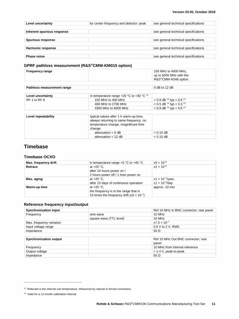
Level uncertainty for center frequency and detector: peak see general technical specifications
Inherent spurious response see general technical specifications
Spurious response see general technical specifications
Harmonic response see general technical specifications
Phase noise see general technical specifications
GPRF pathloss measurement (R&S®CMW-KM015 option)
Frequency range 150 MHz to 4000 MHz,
up to 6000 MHz with the
R&S®CMW-K046 option
Pathloss measurement range 0 dB to 12 dB
Level uncertainty in temperature range +20 °C to +30 °C 12
RF 1 to RF 8 150 MHz to 400 MHz < 0.9 dB 13 typ < 0.6 13
400 MHz to 2700 MHz < 0.5 dB 13 typ < 0.3 13
3300 MHz to 6000 MHz < 0.9 dB 13 typ < 0.6 13
Level repeatability typical values after 1 h warm-up time,
always returning to same frequency, no
temperature change, insignificant time
change
attenuation < 6 dB < 0.10 dB
attenuation < 12 dB < 0.15 dB
Timebase
Timebase OCXO
Max. frequency drift in temperature range +5 °C to +45 °C ±5 × 10⁻⁸
Retrace at +25 °C,
after 24 hours power on /
2 hours power off / 1 hour power on
±2 × 10⁻⁸
Max. aging at +25 °C,
after 10 days of continuous operation
±1 × 10⁻⁷/year,
±1 × 10⁻⁹/day
Warm-up time at +25 °C,
the frequency is in the range that is
10 times the frequency drift (±5 × 10⁻⁷)
approx. 10 min
Reference frequency input/output
Synchronization input Ref 10 MHz In BNC connector, rear panel
Frequency sine wave 10 MHz
square wave (TTL level) 10 MHz
Max. frequency variation ±7.5 × 10⁻⁷
Input voltage range 0.5 V to 2 V, RMS
Impedance 50 Ω
Synchronization output Ref 10 MHz Out BNC connector, rear
panel
Frequency 10 MHz from internal reference
Output voltage > 1.4 V, peak-to-peak
Impedance 50 Ω
12 Relevant is the internal unit temperature, influenced by natural or forced convection.
13 Valid for a 12-month calibration interval.

Version 03.00, October 2018
12 Rohde & Schwarz R&S®CMW100 Communications Manufacturing Test Set
GSM specifications – mobile station test
GSM RF generator Frequency range GSM 450 band 460 MHz to 468 MHz
GSM 480 band 488 MHz to 496 MHz
GSM 750 band 747 MHz to 762 MHz
GSM 850 band 869 MHz to 894 MHz
GSM 900 band 921 MHz to 960 MHz
GSM 1800 band 1805 MHz to 1880 MHz
GSM 1900 band 1930 MHz to 1990 MHz
GSM R&S®WinIQSIM2™ (R&S®CMW-KW200 option),
GSM EDGE Evolution R&S®WinIQSIM2™ (R&S®CMW-KW201 option)
Arbitrary waveform files GMSK, W × D = 0.3, with the
R&S®CMW-KW200 option
GSM_GMSK.WV (PAR = 0 dB),
GMSKDIGMOD.WV (PAR = 0 dB)
8PSK, with the R&S®CMW-KW200 option GSM_EDGE.WV (PAR = 3.23 dB),
EDGEDIGMOD.WV (PAR = 3.22 dB)
Arbitrary waveform files 16QAM, with the R&S®CMW-KW200 and
R&S®CMW-KW201 options
EDGE_EVO_16QAM_A.WV
(PAR = 4.70 dB)
32QAM, with the R&S®CMW-KW200 and
R&S®CMW-KW201 options
EDGE_EVO_32QAM_B.WV
(PAR = 5.37 dB)
Output level range depends on PAR see general technical specifications
Output level uncertainty with the R&S®CMW-KW200 option,
waveform files used:
GMSKDIGMOD.WV or
EDGEDIGMOD.WV
see general technical specifications
with the R&S®CMW-KW200 and
R&S®CMW-KW201 options,
waveform files used:
EDGE_EVO_16QAM_A.WV,
EDGE_EVO_32QAM_B.WV
see general technical specifications
Output level resolution see general technical specifications
Signal quality
Phase error GMSK
with the R&S®CMW-KW200 option,
waveform file used: GSM_GMSK.WV
< 1°, RMS
< 4°, peak
Error vector magnitude (EVM) 8PSK
with the R&S®CMW-KW200 option,
waveform file used: GSM_EDGE.WV
< 2 %, RMS
16QAM / 32QAM level A
with the R&S®CMW-KW200 and
R&S®CMW-KW201 options,
waveform file used:
EDGE_EVO_16QAM_A.WV
< 2 %, RMS
QPSK / 16QAM / 32QAM level B
with the R&S®CMW-KW200 and
R&S®CMW-KW201 options,
waveform file used:
EDGE_EVO_32QAM_B.WV
< 2 %, RMS

Version 03.00, October 2018
Rohde & Schwarz R&S®CMW100 Communications Manufacturing Test Set 13
GSM RF analyzer (R&S®CMW-KM200 option) and GSM EDGE Evolution A analyzer (R&S®CMW-KM201 option)
Frequency range GSM 450 band 450 MHz to 458 MHz
GSM 480 band 478 MHz to 486 MHz
GSM 750 band 777 MHz to 792 MHz
GSM 850 band 824 MHz to 849 MHz
GSM 900 band 876 MHz to 915 MHz
GSM 1800 band 1710 MHz to 1785 MHz
GSM 1900 band 1850 MHz to 1910 MHz
Trigger
Trigger sources BASE: external TRIG IN
GPRF: Gen
GSM: free run
GSM: IF power
GSM: acquisition
Modulation analysis
Level range –28 dBm to +36 dBm 14
Analysis mode with the R&S®CMW-KW200 option GMSK, 8PSK
with the R&S®CMW-KW200 and
R&S®CMW-KW201 options
GMSK, 8PSK, 16QAM (level A)
Inherent phase error GMSK < 0.6°, RMS;
< 2°, peak
Inherent error vector magnitude
(inherent EVM)
8PSK, 16QAM (level A) < 0.8 %, RMS
Frequency measurement uncertainty < 20 Hz + drift of timebase,
see general technical specifications
Inherent I/Q offset < –50 dB
Filter GMSK bandpass, 900 kHz, RRC filter, α = 0.16
8PSK, 16QAM (level A) windowed raised-cosine filter in line with
3GPP TS 45.005
Burst power measurement
Level uncertainty bandpass, 900 kHz, RRC filter, α = 0.16 see general technical specifications
Power versus time measurement
Filter selectable Gaussian, 500 kHz or 1 MHz
Dynamic range filter: 500 kHz, Gaussian,
with fixed expected nominal power setting
GMSK > 72 dB, RMS
8PSK, 16QAM (level A) > 69 dB, RMS
Expected nominal power setting for full
dynamic range
RF1 to RF8 –8 dBm to +36 dBm 14
Relative measurement uncertainty result > –40 dB typ. < 0.1 dB
–60 dB ≤ result ≤ –40 dB typ. < 0.5 dB
Burst power measurement
Level range –50 dBm to +36 dBm 14
Level uncertainty filter: 500 kHz or 1 MHz, Gaussian see general technical specifications
14 The maximum permissible continuous power is +34 dBm due to thermal limits.
Version 03.00, October 2018
14 Rohde & Schwarz R&S®CMW100 Communications Manufacturing Test Set
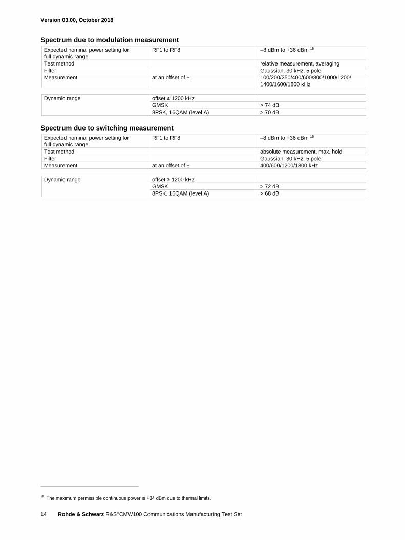
Spectrum due to modulation measurement
Expected nominal power setting for
full dynamic range
RF1 to RF8 –8 dBm to +36 dBm 15
Test method relative measurement, averaging
Filter Gaussian, 30 kHz, 5 pole
Measurement at an offset of ± 100/200/250/400/600/800/1000/1200/
1400/1600/1800 kHz
Dynamic range offset ≥ 1200 kHz
GMSK > 74 dB
8PSK, 16QAM (level A) > 70 dB
Spectrum due to switching measurement
Expected nominal power setting for
full dynamic range
RF1 to RF8 –8 dBm to +36 dBm 15
Test method absolute measurement, max. hold
Filter Gaussian, 30 kHz, 5 pole
Measurement at an offset of ± 400/600/1200/1800 kHz
Dynamic range offset ≥ 1200 kHz
GMSK > 72 dB
8PSK, 16QAM (level A) > 68 dB
15 The maximum permissible continuous power is +34 dBm due to thermal limits.

Version 03.00, October 2018
Rohde & Schwarz R&S®CMW100 Communications Manufacturing Test Set 15
NB-IoT specifications – mobile station test Standard 3GPP NB-IoT HD-FDD
NB-IoT RF generator Frequency range NB-IoT operates in the E-UTRA bands 1, 2,
3, 5, 8, 11, 12, 13, 17, 18, 19, 20, 21, 25,
26, 28, 31, 66
see LTE FDD RF generator specifications
NB-IoT WinIQSIM2™ (R&S®CMW-KW300 option)
Arbitrary waveform file NB-IoT HD-FDD KW300_NB_IOT_64frames_DCI_160ms.wv
(PAR = 8.64 dB)
Output level range depends on PAR see general technical specifications
Output level uncertainty waveform file used:
KW300_NB_IOT_64frames_DCI_160ms.wv
see general technical specifications
Output level resolution see general technical specifications
Signal quality
Error vector magnitude (EVM) EVM NPDSCH QPSK,
bandwidth = 200 kHz
waveform file used:
KW300_NB_IOT_64frames_DCI_160ms.wv
< 2 %, RMS
NB-IoT HD-FDD RF analyzer (R&S®CMW-KM300 option) Bandwidth 200 kHz
Frequency range NB-IoT operates in the E-UTRA bands 1, 2,
3, 5, 8, 12, 13, 17, 18, 19, 20, 26, 28, 66
see LTE FDD RF analyzer specifications
Level setting manual mode
Statistics
Statistical count 1 to 1000
Values current, average, minimum/maximum,
standard deviation
Trigger
Trigger sources BASE: external TRIG IN
GPRF: Gen
NB-IoT: free run
NB-IoT: IF power
Power measurement
Slot power RMS detector
Level range –50 dBm to +30 dBm, RMS
Level uncertainty see general technical specifications
Version 03.00, October 2018
16 Rohde & Schwarz R&S®CMW100 Communications Manufacturing Test Set
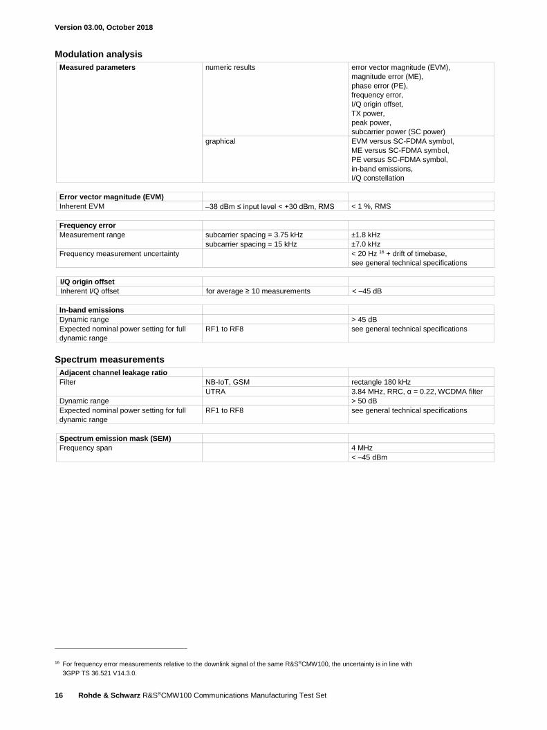
Modulation analysis
Measured parameters numeric results error vector magnitude (EVM),
magnitude error (ME),
phase error (PE),
frequency error,
I/Q origin offset,
TX power,
peak power,
subcarrier power (SC power)
graphical EVM versus SC-FDMA symbol,
ME versus SC-FDMA symbol,
PE versus SC-FDMA symbol,
in-band emissions,
I/Q constellation
Error vector magnitude (EVM)
Inherent EVM –38 dBm ≤ input level < +30 dBm, RMS < 1 %, RMS
Frequency error
Measurement range subcarrier spacing = 3.75 kHz ±1.8 kHz
subcarrier spacing = 15 kHz ±7.0 kHz
Frequency measurement uncertainty < 20 Hz 16 + drift of timebase,
see general technical specifications
I/Q origin offset
Inherent I/Q offset for average ≥ 10 measurements < –45 dB
In-band emissions
Dynamic range > 45 dB
Expected nominal power setting for full
dynamic range
RF1 to RF8 see general technical specifications
Spectrum measurements
Adjacent channel leakage ratio
Filter NB-IoT, GSM rectangle 180 kHz
UTRA 3.84 MHz, RRC, α = 0.22, WCDMA filter
Dynamic range > 50 dB
Expected nominal power setting for full
dynamic range
RF1 to RF8 see general technical specifications
Spectrum emission mask (SEM)
Frequency span 4 MHz
< –45 dBm
16 For frequency error measurements relative to the downlink signal of the same R&S®CMW100, the uncertainty is in line with
3GPP TS 36.521 V14.3.0.

Version 03.00, October 2018
Rohde & Schwarz R&S®CMW100 Communications Manufacturing Test Set 17
WCDMA specifications – mobile station (UE) test Standard 3GPP FDD
WCDMA RF generator Frequency range WCDMA band 1 2112.4 MHz to 2167.6 MHz
WCDMA band 2 1932.4 MHz to 1987.6 MHz
WCDMA band 3 1807.4 MHz to 1877.6 MHz
WCDMA band 4 2112.4 MHz to 2152.6 MHz
WCDMA band 5 871.4 MHz to 891.6 MHz
WCDMA band 6 877.4 MHz to 882.6 MHz
WCDMA band 7 2622.4 MHz to 2687.6 MHz
WCDMA band 8 927.4 MHz to 957.6 MHz
WCDMA band 9 1847.4 MHz to 1877.4 MHz
WCDMA band 10 2112.4 MHz to 2167.6 MHz
WCDMA band 11 1478.4 MHz to 1498.4 MHz
WCDMA band 12 730.4 MHz to 743.6 MHz
WCDMA band 13 748.4 MHz to 753.6 MHz
WCDMA band 14 760.4 MHz to 765.6 MHz
WCDMA band S 2182.4 MHz to 2197.6 MHz
WCDMA band S170 2180 MHz to 2190 MHz
WCDMA band S190 2190 MHz to 2200 MHz
WCDMA R&S®WinIQSIM2™ (R&S®CMW-KW400 option),
WCDMA HSDPA R&S®WinIQSIM2™ (R&S®CMW-KW401 option),
WCDMA HSUPA R&S®WinIQSIM2™ (R&S®CMW-KW402 option),
WCDMA HSPA+ R&S®WinIQSIM2™ (R&S®CMW-KW403 option)
Arbitrary waveform files with the R&S®CMW-KW400 option TM4CPICH.WV (PAR = 8.34 dB),
3GPPDEFAULT.WV (PAR = 10.65 dB)
with the R&S®CMW-KW400 and
R&S®CMW-KW401 options
WCDMA_DL_HSDPA.WV
(PAR = 10.08 dB)
with the R&S®CMW-KW400 and
R&S®CMW-KW401 and
R&S®CMW-KW402 options
WCDMA_DL_HSUPA.WV
(PAR = 10.12 dB)
Output level range depends on PAR see general technical specifications
Output level uncertainty with the R&S®CMW-KW400 option,
waveform file used:
3GPPDEFAULT.WV
see general technical specifications
with the R&S®CMW-KW401 option,
waveform file used:
WCDMA_DL_HSDPA.WV
see general technical specifications
with the R&S®CMW-KW402 option,
waveform file used:
WCDMA_DL_HSUPA.WV
see general technical specifications
with the R&S®CMW-KW400 and
R&S®CMW-KW401 and
R&S®CMW-KW402 and
R&S®CMW-KW403 options
see general technical specifications
Output level resolution see general technical specifications

Version 03.00, October 2018
18 Rohde & Schwarz R&S®CMW100 Communications Manufacturing Test Set
Signal quality
Error vector magnitude (EVM) composite EVM,
with the R&S®CMW-KW400 option,
waveform file used:
TM4CPICH.WV
< 2 %, RMS
composite EVM,
with the R&S®CMW-KW401 option,
waveform file used:
WCDMA_DL_HSDPA.WV
< 2 %, RMS
composite EVM,
with the R&S®CMW-KW402 option,
waveform file used:
WCDMA_DL_HSUPA.WV
< 2 %, RMS
with the R&S®CMW-KW400 and
R&S®CMW-KW401 and
R&S®CMW-KW402 and
R&S®CMW-KW403 options
< 2 %, RMS
WCDMA RF analyzer (R&S®CMW-KM400, R&S®CMW-KM401, R&S®CMW-KM403 options)
Frequency range WCDMA band 1 1922.4 MHz to 1977.6 MHz
WCDMA band 2 1852.4 MHz to 1907.6 MHz
WCDMA band 3 1712.4 MHz to 1782.6 MHz
WCDMA band 4 1712.4 MHz to 1752.6 MHz
WCDMA band 5 826.4 MHz to 846.6 MHz
WCDMA band 6 832.4 MHz to 837.6 MHz
WCDMA band 7 2502.4 MHz to 2567.6 MHz
WCDMA band 8 882.4 MHz to 912.6 MHz
WCDMA band 9 1752.4 MHz to 1782.4 MHz
WCDMA band 10 1712.4 MHz to 1767.6 MHz
WCDMA band 11 1430.4 MHz to 1450.4 MHz
WCDMA band 12 700.4 MHz to 713.6 MHz
WCDMA band 13 779.4 MHz to 784.6 MHz
WCDMA band 14 790.4 MHz to 795.6 MHz
WCDMA band S 2002.4 MHz to 2017.6 MHz
WCDMA band S170 2010 MHz to 2020 MHz
WCDMA band S190 2000 MHz to 2010 MHz
Statistics
Statistical count 1 to 1000
Values current, average, minimum/maximum,
standard deviation
Trigger
Trigger sources BASE: external TRIG IN
GPRF: Gen
WCDMA: free run
WCDMA: free run (fast sync)
WCDMA: IF power
WCDMA: DCCH TTI trigger
WCDMA: frame trigger
WCDMA: HS-DPCCH trigger
WCDMA: slot trigger

Version 03.00, October 2018
Rohde & Schwarz R&S®CMW100 Communications Manufacturing Test Set 19
Modulation analysis
Filter 3.84 MHz, RRC, α = 0.22, WCDMA filter
Level range –28 dBm to +36 dBm 17
Analysis modes with the R&S®CMW-KM400 option QPSK, WCDMA
with the R&S®CMW-KM400 and
R&S®CMW-KM401 options
WCDMA + HSDPA, WCDMA + HSUPA,
WCDMA + HSPA
with the R&S®CMW-KM400 and
R&S®CMW-KM401 and
R&S®CMW-KM403 options
WCDMA + HSPA+
Measured parameters numeric results and standard deviation error vector magnitude (EVM),
magnitude error (ME),
phase error (PE),
frequency error,
I/Q origin offset,
I/Q imbalance,
UE power,
power steps,
phase discontinuity,
CDP,
CDE
graphical EVM versus time, EVM versus chip,
ME versus time, ME versus chip,
PE versus time, PE versus chip,
FE versus time,
UE versus time,
PS versus slot,
PD versus slot,
CDP versus slot,
CDE versus slot,
CD monitor
Error vector magnitude (EVM)
Measurement range up to 25 %, RMS
Inherent EVM < 2.5 %, RMS
Measurement length half-slot, 1 slot, multislot (1 to 120)
Frequency error
Measurement range ±3 kHz
Frequency measurement uncertainty
< 20 Hz + drift of timebase,
see general technical specifications
I/Q origin offset
Inherent I/Q offset for average ≥ 10 measurements < –55 dB
I/Q imbalance
Inherent I/Q imbalance < –50 dB
Spectrum measurements
Adjacent channel leakage ratio RMS detector
Filter 3.84 MHz, RRC, α = 0.22, WCDMA filter
Dynamic range first adjacent channel at ±5 MHz > 54 dB
second adjacent channel at ±10 MHz > 57 dB
Expected nominal power setting for
full dynamic range
RF1 to RF8 –4 dBm to +36 dBm 17
Uncertainty for –33 dBc first adjacent channel level < 0.5 dB
for –43 dBc second adjacent channel level < 0.5 dB
Measurement length 1 slot (2560 chip)
17 The maximum permissible continuous power is +34 dBm due to thermal limits.

Version 03.00, October 2018
20 Rohde & Schwarz R&S®CMW100 Communications Manufacturing Test Set
Power meter
UE power measurement RMS detector
Filter bandpass, 6.3 MHz, RRC, α = 0.22
Level range –55 dBm to +36 dBm 18
Level uncertainty see general technical specifications
Measurement length half-slot, 1 slot
Off power measurement RMS detector
Filter 3.84 MHz, RRC, α = 0.22, WCDMA filter
Noise floor –72 dBm
Level uncertainty see general technical specifications +
uncertainty due to noise floor
18 The maximum permissible continuous power is +34 dBm due to thermal limits.

Version 03.00, October 2018
Rohde & Schwarz R&S®CMW100 Communications Manufacturing Test Set 21
WCDMA specifications – small cell test
WCDMA RF analyzer (R&S®CMW-KN400) Frequency range WCDMA band 1 2112.4 MHz to 2167.6 MHz
WCDMA band 2 1932.4 MHz to 1987.6 MHz
WCDMA band 3 1807.4 MHz to 1877.6 MHz
WCDMA band 4 2112.4 MHz to 2152.6 MHz
WCDMA band 5 871.4 MHz to 891.6 MHz
WCDMA band 6 877.4 MHz to 882.6 MHz
WCDMA band 7 2622.4 MHz to 2687.6 MHz
WCDMA band 8 927.4 MHz to 957.6 MHz
WCDMA band 9 1847.4 MHz to 1877.4 MHz
WCDMA band 10 2112.4 MHz to 2167.6 MHz
WCDMA band 11 1478.4 MHz to 1498.4 MHz
WCDMA band 12 730.4 MHz to 743.6 MHz
WCDMA band 13 748.4 MHz to 753.6 MHz
WCDMA band 14 760.4 MHz to 765.6 MHz
WCDMA band S 2182.4 MHz to 2197.6 MHz
WCDMA band S170 2180 MHz to 2190 MHz
WCDMA band S190 2190 MHz to 2200 MHz
Statistics
Statistical count 1 to 1000
Values current, average, minimum/maximum,
standard deviation
Trigger
Trigger sources BASE: external TRIG IN
GPRF: Gen
WCDMA: free run
WCDMA: free run (fast sync)
WCDMA: IF power
WCDMA: DCCH TTI trigger
WCDMA: frame trigger
WCDMA: HS-DPCCH trigger
WCDMA: slot trigger
Modulation analysis
Filter 3.84 MHz, RRC, α = 0.22, WCDMA filter
Level range –28 dBm to +36 dBm 19
Analysis modes with the R&S®CMW-KM400 option QPSK, WCDMA
Measured parameters numeric results and standard deviation error vector magnitude (EVM),
magnitude error (ME),
phase error (PE),
frequency error,
I/Q origin offset,
I/Q imbalance,
UE power,
power steps,
phase discontinuity,
CDP,
CDE
19 The maximum permissible continuous power is +34 dBm due to thermal limits.

Version 03.00, October 2018
22 Rohde & Schwarz R&S®CMW100 Communications Manufacturing Test Set
graphical EVM versus time, EVM versus chip,
ME versus time, ME versus chip,
PE versus time, PE versus chip,
FE versus time,
UE versus time,
PS versus slot,
PD versus slot,
CDP versus slot,
CDE versus slot,
CD monitor
Error vector magnitude (EVM)
Measurement range up to 25 %, RMS
Inherent EVM < 2.5 %, RMS
Measurement length half-slot, 1 slot, multislot (1 to 120)
Frequency error
Measurement range ±3 kHz
Frequency measurement uncertainty < 20 Hz + drift of timebase,
see general technical specifications
I/Q origin offset
Inherent I/Q offset for average ≥ 10 measurements < –52 dB
I/Q imbalance
Inherent I/Q imbalance < –50 dB
Spectrum measurements
Adjacent channel leakage ratio RMS detector
Filter 3.84 MHz, RRC, α = 0.22, WCDMA filter
Dynamic range first adjacent channel at ±5 MHz > 52 dB
second adjacent channel at ±10 MHz > 52 dB
Expected nominal power setting for full
dynamic range
RF1 to RF8 –4 dBm to +36 dBm 20
Uncertainty for –33 dBc first adjacent channel level < 0.5 dB
for –43 dBc second adjacent channel level < 0.5 dB
Measurement length 1 slot (2560 chip)
Power meter
UE power measurement RMS detector
Filter bandpass, 6.3 MHz, RRC, α = 0.22
Level range –55 dBm to +36 dBm 20
Level uncertainty see general technical specifications
Measurement length half-slot, 1 slot
Off power measurement RMS detector
Filter 3.84 MHz, RRC, α = 0.22, WCDMA filter
Noise floor –72 dBm
Level uncertainty see general technical specifications +
uncertainty due to noise floor
20 The maximum permissible continuous power is +34 dBm due to thermal limits.
Version 03.00, October 2018
Rohde & Schwarz R&S®CMW100 Communications Manufacturing Test Set 23
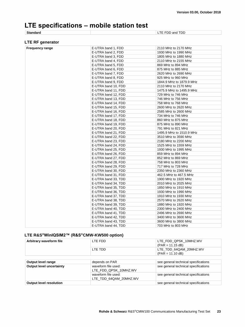
LTE specifications – mobile station test Standard LTE FDD and TDD
LTE RF generator
Frequency range E-UTRA band 1, FDD 2110 MHz to 2170 MHz
E-UTRA band 2, FDD 1930 MHz to 1990 MHz
E-UTRA band 3, FDD 1805 MHz to 1880 MHz
E-UTRA band 4, FDD 2110 MHz to 2155 MHz
E-UTRA band 5, FDD 869 MHz to 894 MHz
E-UTRA band 6, FDD 875 MHz to 885 MHz
E-UTRA band 7, FDD 2620 MHz to 2690 MHz
E-UTRA band 8, FDD 925 MHz to 960 MHz
E-UTRA band 9, FDD 1844.9 MHz to 1879.9 MHz
E-UTRA band 10, FDD 2110 MHz to 2170 MHz
E-UTRA band 11, FDD 1475.9 MHz to 1495.9 MHz
E-UTRA band 12, FDD 729 MHz to 746 MHz
E-UTRA band 13, FDD 746 MHz to 756 MHz
E-UTRA band 14, FDD 758 MHz to 768 MHz
E-UTRA band 15, FDD 2600 MHz to 2620 MHz
E-UTRA band 16, FDD 2585 MHz to 2600 MHz
E-UTRA band 17, FDD 734 MHz to 746 MHz
E-UTRA band 18, FDD 860 MHz to 875 MHz
E-UTRA band 19, FDD 875 MHz to 890 MHz
E-UTRA band 20, FDD 791 MHz to 821 MHz
E-UTRA band 21, FDD 1495.9 MHz to 1510.9 MHz
E-UTRA band 22, FDD 3510 MHz to 3590 MHz
E-UTRA band 23, FDD 2180 MHz to 2200 MHz
E-UTRA band 24, FDD 1525 MHz to 1559 MHz
E-UTRA band 25, FDD 1930 MHz to 1995 MHz
E-UTRA band 26, FDD 859 MHz to 894 MHz
E-UTRA band 27, FDD 852 MHz to 869 MHz
E-UTRA band 28, FDD 758 MHz to 803 MHz
E-UTRA band 29, FDD 717 MHz to 728 MHz
E-UTRA band 30, FDD 2350 MHz to 2360 MHz
E-UTRA band 31, FDD 462.5 MHz to 467.5 MHz
E-UTRA band 33, TDD 1900 MHz to 1920 MHz
E-UTRA band 34, TDD 2010 MHz to 2025 MHz
E-UTRA band 35, TDD 1850 MHz to 1910 MHz
E-UTRA band 36, TDD 1930 MHz to 1990 MHz
E-UTRA band 37, TDD 1910 MHz to 1930 MHz
E-UTRA band 38, TDD 2570 MHz to 2620 MHz
E-UTRA band 39, TDD 1880 MHz to 1920 MHz
E-UTRA band 40, TDD 2300 MHz to 2400 MHz
E-UTRA band 41, TDD 2496 MHz to 2690 MHz
E-UTRA band 42, TDD 3400 MHz to 3600 MHz
E-UTRA band 43, TDD 3600 MHz to 3800 MHz
E-UTRA band 44, TDD 703 MHz to 803 MHz
LTE R&S®WinIQSIM2™ (R&S®CMW-KW500 option)
Arbitrary waveform file LTE FDD LTE_FDD_QPSK_10MHZ.WV
(PAR = 11.15 dB)
LTE TDD LTE_TDD_64QAM_20MHZ.WV
(PAR = 11.10 dB)
Output level range depends on PAR see general technical specifications
Output level uncertainty waveform file used:
LTE_FDD_QPSK_10MHZ.WV
see general technical specifications
waveform file used:
LTE_TDD_64QAM_20MHZ.WV
see general technical specifications
Output level resolution see general technical specifications
Version 03.00, October 2018
24 Rohde & Schwarz R&S®CMW100 Communications Manufacturing Test Set
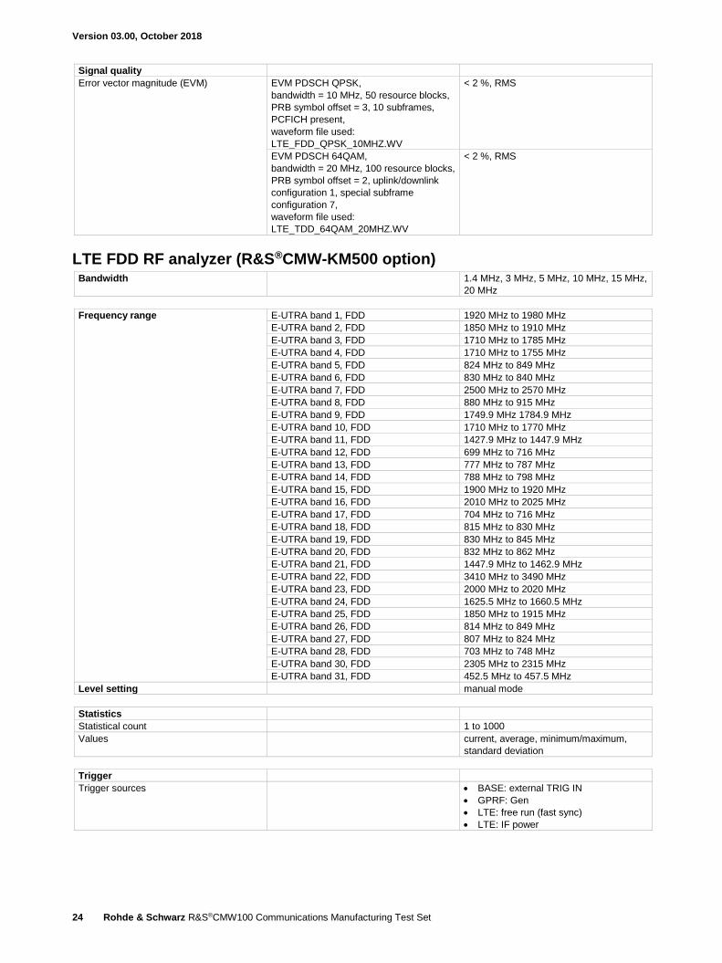
Signal quality
Error vector magnitude (EVM) EVM PDSCH QPSK,
bandwidth = 10 MHz, 50 resource blocks,
PRB symbol offset = 3, 10 subframes,
PCFICH present,
waveform file used:
LTE_FDD_QPSK_10MHZ.WV
< 2 %, RMS
EVM PDSCH 64QAM,
bandwidth = 20 MHz, 100 resource blocks,
PRB symbol offset = 2, uplink/downlink
configuration 1, special subframe
configuration 7,
waveform file used:
LTE_TDD_64QAM_20MHZ.WV
< 2 %, RMS
LTE FDD RF analyzer (R&S®CMW-KM500 option) Bandwidth 1.4 MHz, 3 MHz, 5 MHz, 10 MHz, 15 MHz,
20 MHz
Frequency range E-UTRA band 1, FDD 1920 MHz to 1980 MHz
E-UTRA band 2, FDD 1850 MHz to 1910 MHz
E-UTRA band 3, FDD 1710 MHz to 1785 MHz
E-UTRA band 4, FDD 1710 MHz to 1755 MHz
E-UTRA band 5, FDD 824 MHz to 849 MHz
E-UTRA band 6, FDD 830 MHz to 840 MHz
E-UTRA band 7, FDD 2500 MHz to 2570 MHz
E-UTRA band 8, FDD 880 MHz to 915 MHz
E-UTRA band 9, FDD 1749.9 MHz 1784.9 MHz
E-UTRA band 10, FDD 1710 MHz to 1770 MHz
E-UTRA band 11, FDD 1427.9 MHz to 1447.9 MHz
E-UTRA band 12, FDD 699 MHz to 716 MHz
E-UTRA band 13, FDD 777 MHz to 787 MHz
E-UTRA band 14, FDD 788 MHz to 798 MHz
E-UTRA band 15, FDD 1900 MHz to 1920 MHz
E-UTRA band 16, FDD 2010 MHz to 2025 MHz
E-UTRA band 17, FDD 704 MHz to 716 MHz
E-UTRA band 18, FDD 815 MHz to 830 MHz
E-UTRA band 19, FDD 830 MHz to 845 MHz
E-UTRA band 20, FDD 832 MHz to 862 MHz
E-UTRA band 21, FDD 1447.9 MHz to 1462.9 MHz
E-UTRA band 22, FDD 3410 MHz to 3490 MHz
E-UTRA band 23, FDD 2000 MHz to 2020 MHz
E-UTRA band 24, FDD 1625.5 MHz to 1660.5 MHz
E-UTRA band 25, FDD 1850 MHz to 1915 MHz
E-UTRA band 26, FDD 814 MHz to 849 MHz
E-UTRA band 27, FDD 807 MHz to 824 MHz
E-UTRA band 28, FDD 703 MHz to 748 MHz
E-UTRA band 30, FDD 2305 MHz to 2315 MHz
E-UTRA band 31, FDD 452.5 MHz to 457.5 MHz
Level setting manual mode
Statistics
Statistical count 1 to 1000
Values current, average, minimum/maximum,
standard deviation
Trigger
Trigger sources BASE: external TRIG IN
GPRF: Gen
LTE: free run (fast sync)
LTE: IF power
Version 03.00, October 2018
Rohde & Schwarz R&S®CMW100 Communications Manufacturing Test Set 25
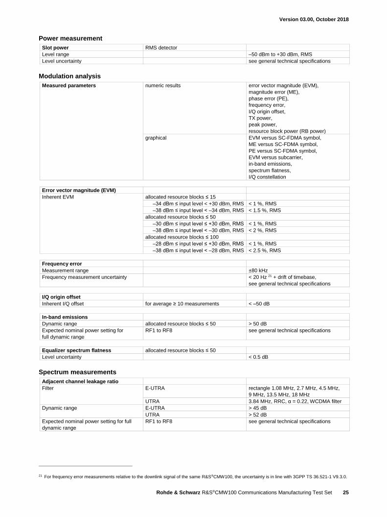
Power measurement
Slot power RMS detector
Level range –50 dBm to +30 dBm, RMS
Level uncertainty see general technical specifications
Modulation analysis
Measured parameters numeric results error vector magnitude (EVM),
magnitude error (ME),
phase error (PE),
frequency error,
I/Q origin offset,
TX power,
peak power,
resource block power (RB power)
graphical EVM versus SC-FDMA symbol,
ME versus SC-FDMA symbol,
PE versus SC-FDMA symbol,
EVM versus subcarrier,
in-band emissions,
spectrum flatness,
I/Q constellation
Error vector magnitude (EVM)
Inherent EVM allocated resource blocks ≤ 15
–34 dBm ≤ input level < +30 dBm, RMS < 1 %, RMS
–38 dBm ≤ input level < –34 dBm, RMS < 1.5 %, RMS
allocated resource blocks ≤ 50
–30 dBm ≤ input level ≤ +30 dBm, RMS < 1 %, RMS
–38 dBm ≤ input level < –30 dBm, RMS < 2 %, RMS
allocated resource blocks ≤ 100
–28 dBm ≤ input level ≤ +30 dBm, RMS < 1 %, RMS
–38 dBm ≤ input level < –28 dBm, RMS < 2.5 %, RMS
Frequency error
Measurement range ±80 kHz
Frequency measurement uncertainty < 20 Hz 21 + drift of timebase,
see general technical specifications
I/Q origin offset
Inherent I/Q offset for average ≥ 10 measurements < –50 dB
In-band emissions
Dynamic range allocated resource blocks ≤ 50 > 50 dB
Expected nominal power setting for
full dynamic range
RF1 to RF8 see general technical specifications
Equalizer spectrum flatness allocated resource blocks ≤ 50
Level uncertainty < 0.5 dB
Spectrum measurements
Adjacent channel leakage ratio
Filter E-UTRA rectangle 1.08 MHz, 2.7 MHz, 4.5 MHz,
9 MHz, 13.5 MHz, 18 MHz
UTRA 3.84 MHz, RRC, α = 0.22, WCDMA filter
Dynamic range E-UTRA > 45 dB
UTRA > 52 dB
Expected nominal power setting for full
dynamic range
RF1 to RF8 see general technical specifications
21 For frequency error measurements relative to the downlink signal of the same R&S®CMW100, the uncertainty is in line with 3GPP TS 36.521-1 V9.3.0.
Version 03.00, October 2018
26 Rohde & Schwarz R&S®CMW100 Communications Manufacturing Test Set
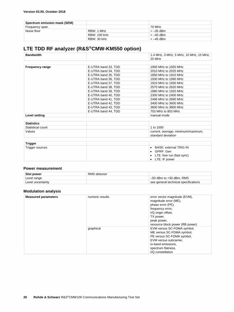
Spectrum emission mask (SEM)
Frequency span 70 MHz
Noise floor RBW: 1 MHz < –35 dBm
RBW: 100 kHz < –40 dBm
RBW: 30 kHz < –45 dBm
LTE TDD RF analyzer (R&S®CMW-KM550 option) Bandwidth 1.4 MHz, 3 MHz, 5 MHz, 10 MHz, 15 MHz,
20 MHz
Frequency range E-UTRA band 33, TDD 1900 MHz to 1920 MHz
E-UTRA band 34, TDD 2010 MHz to 2025 MHz
E-UTRA band 35, TDD 1850 MHz to 1910 MHz
E-UTRA band 36, TDD 1930 MHz to 1990 MHz
E-UTRA band 37, TDD 1910 MHz to 1930 MHz
E-UTRA band 38, TDD 2570 MHz to 2620 MHz
E-UTRA band 39, TDD 1880 MHz to 1920 MHz
E-UTRA band 40, TDD 2300 MHz to 2400 MHz
E-UTRA band 41, TDD 2496 MHz to 2690 MHz
E-UTRA band 42, TDD 3400 MHz to 3600 MHz
E-UTRA band 43, TDD 3600 MHz to 3800 MHz
E-UTRA band 44, TDD 703 MHz to 803 MHz
Level setting manual mode
Statistics
Statistical count 1 to 1000
Values current, average, minimum/maximum,
standard deviation
Trigger
Trigger sources BASE: external TRIG IN
GPRF: Gen
LTE: free run (fast sync)
LTE: IF power
Power measurement
Slot power RMS detector
Level range –50 dBm to +30 dBm, RMS
Level uncertainty see general technical specifications
Modulation analysis
Measured parameters numeric results error vector magnitude (EVM),
magnitude error (ME),
phase error (PE),
frequency error,
I/Q origin offset,
TX power,
peak power,
resource block power (RB power)
graphical EVM versus SC-FDMA symbol,
ME versus SC-FDMA symbol,
PE versus SC-FDMA symbol,
EVM versus subcarrier,
in-band emissions,
spectrum flatness,
I/Q constellation

Version 03.00, October 2018
Rohde & Schwarz R&S®CMW100 Communications Manufacturing Test Set 27
Error vector magnitude (EVM)
Inherent EVM allocated resource blocks ≤ 15
–34 dBm ≤ input level < +30 dBm,
RMS
< 1 %, RMS
–38 dBm ≤ input level < –34 dBm, RMS < 1.5 %, RMS
allocated resource blocks ≤ 50
–30 dBm ≤ input level ≤ +30 dBm, RMS < 1 %, RMS
–38 dBm ≤ input level < –30 dBm, RMS < 2 %, RMS
allocated resource blocks ≤ 100
–28 dBm ≤ input level ≤ +30 dBm, RMS < 1 %, RMS
–38 dBm ≤ input level < –28 dBm, RMS < 2.5 %, RMS
Frequency error
Measurement range ±80 kHz
Frequency measurement uncertainty < 20 Hz 22 + drift of timebase,
see general technical specifications
I/Q origin offset
Inherent I/Q offset < –50 dB
In-band emissions
Dynamic range allocated resource blocks ≤ 50 > 50 dB
Expected nominal power setting for full
dynamic range
RF1 to RF8 see general technical specifications
Equalizer spectrum flatness allocated resource blocks ≤ 50
Level uncertainty < 0.5 dB
Spectrum measurements
Adjacent channel leakage ratio
Filter E-UTRA rectangle 1.08 MHz, 2.7 MHz, 4.5 MHz,
9 MHz, 13.5 MHz, 18 MHz
UTRA 1.28 MHz, RRC, α = 0.22, WCDMA filter
Dynamic range E-UTRA > 45 dB
UTRA > 56 dB
Expected nominal power setting for full
dynamic range
RF1 to RF8 see general technical specifications
Spectrum emission mask (SEM)
Frequency span 70 MHz
Noise floor RBW: 1 MHz < –35 dBm
RBW: 100 kHz < –40 dBm
RBW: 30 kHz < –45 dBm
LTE C-V2X RF analyzer (R&S®CMW-KM570 option) Bandwidth 1.4 MHz, 3 MHz, 5 MHz, 10 MHz, 15 MHz,
20 MHz
Frequency range E-UTRA band 47, TDD 5855 MHz to 5925 MHz
Level setting manual mode
Statistics
Statistical count 1 to 1000
Values current, average, minimum/maximum,
standard deviation
Trigger
Trigger sources BASE: external TRIG IN
GPRF: Gen
LTE: free run (fast sync)
LTE: IF power
22 For frequency error measurements relative to the downlink signal of the same R&S®CMW100, the uncertainty is in line with 3GPP TS 36.521-1 V9.3.0.

Version 03.00, October 2018
28 Rohde & Schwarz R&S®CMW100 Communications Manufacturing Test Set
Power measurement
Slot power RMS detector
Level range –50 dBm to +30 dBm, RMS
Level uncertainty see general technical specifications
Modulation analysis
Measured parameters numeric results error vector magnitude (EVM),
magnitude error (ME),
phase error (PE),
frequency error,
I/Q origin offset,
TX power,
peak power,
resource block power (RB power)
graphical EVM versus SC-FDMA symbol,
ME versus SC-FDMA symbol,
PE versus SC-FDMA symbol,
EVM versus subcarrier,
in-band emissions,
spectrum flatness,
I/Q constellation
Error vector magnitude (EVM)
Inherent EVM allocated resource blocks ≤ 15
–34 dBm ≤ input level < +30 dBm,
RMS
< 1 %, RMS
–38 dBm ≤ input level < –34 dBm, RMS < 1.5 %, RMS
allocated resource blocks ≤ 50
–30 dBm ≤ input level ≤ +30 dBm, RMS < 1 %, RMS
–38 dBm ≤ input level < –30 dBm, RMS < 2 %, RMS
allocated resource blocks ≤ 100
–28 dBm ≤ input level ≤ +30 dBm, RMS < 1 %, RMS
–38 dBm ≤ input level < –28 dBm, RMS < 2.5 %, RMS
Frequency error
Measurement range ±80 kHz
Frequency measurement uncertainty < 35 Hz + drift of timebase,
see general technical specifications
I/Q origin offset
Inherent I/Q offset < –50 dB
In-band emissions
Dynamic range allocated resource blocks ≤ 50 > 50 dB
Expected nominal power setting for full
dynamic range
RF1 to RF8 see general technical specifications
Equalizer spectrum flatness allocated resource blocks ≤ 50
Level uncertainty < 0.5 dB
Spectrum measurements
Adjacent channel leakage ratio
Filter E-UTRA rectangle 1.08 MHz, 2.7 MHz, 4.5 MHz,
9 MHz, 13.5 MHz, 18 MHz
UTRA 1.28 MHz, RRC, α = 0.22, WCDMA filter
Dynamic range E-UTRA > 45 dB
UTRA > 56 dB
Expected nominal power setting for full
dynamic range
RF1 to RF8 see general technical specifications
Spectrum emission mask (SEM)
Frequency span 70 MHz
Noise floor RBW: 1 MHz < –37 dBm
RBW: 100 kHz < –42 dBm
RBW: 30 kHz < –47 dBm
Version 03.00, October 2018
Rohde & Schwarz R&S®CMW100 Communications Manufacturing Test Set 29
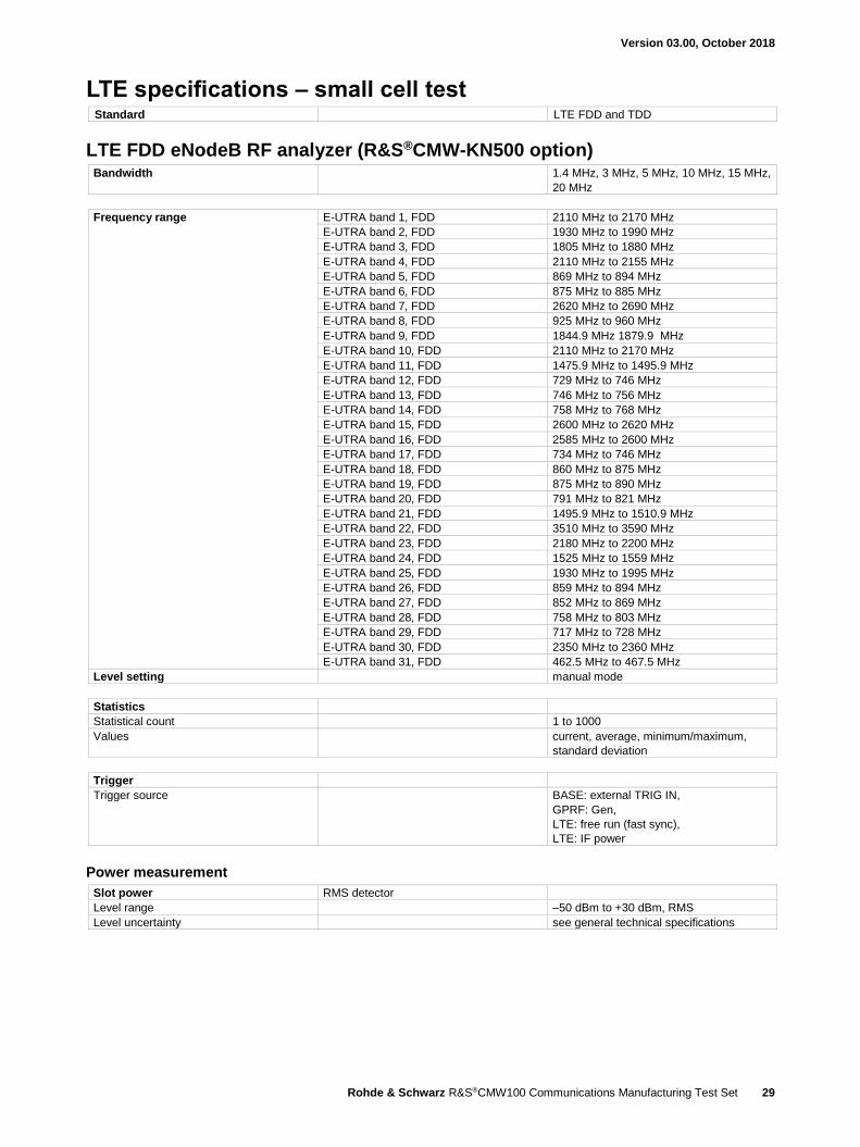
LTE specifications – small cell test Standard LTE FDD and TDD
LTE FDD eNodeB RF analyzer (R&S®CMW-KN500 option) Bandwidth 1.4 MHz, 3 MHz, 5 MHz, 10 MHz, 15 MHz,
20 MHz
Frequency range E-UTRA band 1, FDD 2110 MHz to 2170 MHz
E-UTRA band 2, FDD 1930 MHz to 1990 MHz
E-UTRA band 3, FDD 1805 MHz to 1880 MHz
E-UTRA band 4, FDD 2110 MHz to 2155 MHz
E-UTRA band 5, FDD 869 MHz to 894 MHz
E-UTRA band 6, FDD 875 MHz to 885 MHz
E-UTRA band 7, FDD 2620 MHz to 2690 MHz
E-UTRA band 8, FDD 925 MHz to 960 MHz
E-UTRA band 9, FDD 1844.9 MHz 1879.9 MHz
E-UTRA band 10, FDD 2110 MHz to 2170 MHz
E-UTRA band 11, FDD 1475.9 MHz to 1495.9 MHz
E-UTRA band 12, FDD 729 MHz to 746 MHz
E-UTRA band 13, FDD 746 MHz to 756 MHz
E-UTRA band 14, FDD 758 MHz to 768 MHz
E-UTRA band 15, FDD 2600 MHz to 2620 MHz
E-UTRA band 16, FDD 2585 MHz to 2600 MHz
E-UTRA band 17, FDD 734 MHz to 746 MHz
E-UTRA band 18, FDD 860 MHz to 875 MHz
E-UTRA band 19, FDD 875 MHz to 890 MHz
E-UTRA band 20, FDD 791 MHz to 821 MHz
E-UTRA band 21, FDD 1495.9 MHz to 1510.9 MHz
E-UTRA band 22, FDD 3510 MHz to 3590 MHz
E-UTRA band 23, FDD 2180 MHz to 2200 MHz
E-UTRA band 24, FDD 1525 MHz to 1559 MHz
E-UTRA band 25, FDD 1930 MHz to 1995 MHz
E-UTRA band 26, FDD 859 MHz to 894 MHz
E-UTRA band 27, FDD 852 MHz to 869 MHz
E-UTRA band 28, FDD 758 MHz to 803 MHz
E-UTRA band 29, FDD 717 MHz to 728 MHz
E-UTRA band 30, FDD 2350 MHz to 2360 MHz
E-UTRA band 31, FDD 462.5 MHz to 467.5 MHz
Level setting manual mode
Statistics
Statistical count 1 to 1000
Values current, average, minimum/maximum,
standard deviation
Trigger
Trigger source BASE: external TRIG IN,
GPRF: Gen,
LTE: free run (fast sync),
LTE: IF power
Power measurement
Slot power RMS detector
Level range –50 dBm to +30 dBm, RMS
Level uncertainty see general technical specifications

Version 03.00, October 2018
30 Rohde & Schwarz R&S®CMW100 Communications Manufacturing Test Set
Modulation analysis
Measured parameters numeric results error vector magnitude (EVM),
magnitude error (ME),
phase error (PE),
frequency error,
I/Q origin offset,
TX power,
peak power,
reference symbol power,
OFDM symbol power
graphical EVM versus OFDMA symbol,
ME versus OFDMA symbol,
PE versus OFDMA symbol,
OFDM symbol power
spectrum flatness,
spectrum ACLR
I/Q constellation
Error vector magnitude (EVM)
Inherent EVM for average ≥ 10 subframes
–20 dBm ≤ input level < +30 dBm,
RMS
< 1.5 %, RMS
Frequency error
Measurement range ±80 kHz
Frequency measurement uncertainty < 20 Hz 23 + drift of timebase,
see general technical specifications
Spectrum measurements
Adjacent channel leakage ratio
Filter E-UTRA rectangle 1.08 MHz, 2.7 MHz, 4.5 MHz,
9 MHz, 13.5 MHz, 18 MHz
UTRA 1.28 MHz, RRC, α = 0.22, WCDMA filter
3.84 MHz, RRC, α = 0.22, WCDMA filter
7.68 MHz, RRC, α = 0.22, WCDMA filter
Dynamic range E-UTRA > 50 dB
UTRA384 > 52 dB
Expected nominal power setting for full
dynamic range
RF1 to RF8 see general technical specifications
Spectrum emission mask (SEM)
Frequency span 70 MHz
Noise floor RBW: ≤ 1 MHz, expected nominal power
< 12 dBm
< –58 dBm
23 For frequency error measurements relative to the downlink signal of the same R&S®CMW100, the uncertainty is in line with 3GPP TS 36.521-1 V9.3.0.
Version 03.00, October 2018
Rohde & Schwarz R&S®CMW100 Communications Manufacturing Test Set 31
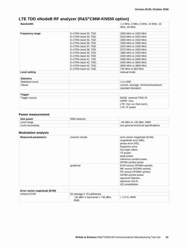
LTE TDD eNodeB RF analyzer (R&S®CMW-KN550 option) Bandwidth 1.4 MHz, 3 MHz, 5 MHz, 10 MHz, 15
MHz, 20 MHz
Frequency range E-UTRA band 33, TDD 1900 MHz to 1920 MHz
E-UTRA band 34, TDD 2010 MHz to 2025 MHz
E-UTRA band 35, TDD 1850 MHz to 1910 MHz
E-UTRA band 36, TDD 1930 MHz to 1990 MHz
E-UTRA band 37, TDD 1910 MHz to 1930 MHz
E-UTRA band 38, TDD 2570 MHz to 2620 MHz
E-UTRA band 39, TDD 1880 MHz to 1920 MHz
E-UTRA band 40, TDD 2300 MHz to 2400 MHz
E-UTRA band 41, TDD 2496 MHz to 2690 MHz
E-UTRA band 42, TDD, 3400 MHz to 3600 MHz
E-UTRA band 43, TDD, 3600 MHz to 3800 MHz
E-UTRA band 44, TDD 703 MHz to 803 MHz
Level setting manual mode
Statistics
Statistical count 1 to 1000
Values
current, average, minimum/maximum,
standard deviation
Trigger
Trigger source BASE: external TRIG IN
GPRF: Gen,
LTE: free run (fast sync),
LTE: IF power
Power measurement
Slot power RMS detector
Level range –50 dBm to +30 dBm, RMS
Level uncertainty see general technical specifications
Modulation analysis
Measured parameters numeric results error vector magnitude (EVM),
magnitude error (ME),
phase error (PE),
frequency error,
I/Q origin offset,
TX power,
peak power,
reference symbol power,
OFDM symbol power
graphical EVM versus OFDMA symbol,
ME versus OFDMA symbol,
PE versus OFDMA symbol,
OFDM symbol power
spectrum flatness,
spectrum ACLR,
I/Q constellation
Error vector magnitude (EVM)
Inherent EVM for average ≥ 10 subframes
–20 dBm ≤ input level < +30 dBm,
RMS
< 1.5 %, RMS

Version 03.00, October 2018
32 Rohde & Schwarz R&S®CMW100 Communications Manufacturing Test Set
Frequency error
Measurement range ±80 kHz
Frequency measurement uncertainty < 20 Hz 24 + drift of timebase,
see general technical specifications
Spectrum measurements
Adjacent channel leakage ratio
Filter E-UTRA rectangle 1.08 MHz, 2.7 MHz, 4.5 MHz,
9 MHz, 13.5 MHz, 18 MHz
UTRA 1.28 MHz, RRC, α = 0.22, WCDMA filter
3.84 MHz, RRC, α = 0.22, WCDMA filter
7.68 MHz, RRC, α = 0.22, WCDMA filter
Dynamic range E-UTRA > 50 dB
UTRA128 > 52 dB
UTRA384 > 52 dB
UTRA768 > 49 dB
Expected nominal power setting for full
dynamic range
RF1 to RF8 see general technical specifications
Spectrum emission mask (SEM)
Frequency span 70 MHz
Noise floor RBW: ≤ 1 MHz, expected nominal power
< 12 dBm
< –58 dBm
24 For frequency error measurements relative to the downlink signal of the same R&S®CMW100, the uncertainty is in line with 3GPP TS 36.521-1 V9.3.0.

Version 03.00, October 2018
Rohde & Schwarz R&S®CMW100 Communications Manufacturing Test Set 33
Bluetooth® specifications Standard standard Bluetooth® Core Specification
Version 5.0
test standard Radio Frequency Bluetooth® Test
Specification RF.TS.5.0.0,
Low Energy RF PHY Bluetooth® Test
Specification, RF-PHY.TS.5.0.0
Bluetooth® RF generator Frequency range Bluetooth® 2402 MHz to 2480 MHz
Bluetooth® R&S®WinIQSIM2™ (R&S®CMW-KW610 option)
Arbitrary waveform file basic rate BLUETOOTH_11110000_DH5.WV
LAP: 123456, (PAR = 0.00 dB)
enhanced data rate (EDR) BLUETOOTH_PRBS9_3-DH5.WV
LAP: 123456, (PAR = 3.20 dB)
Output level range depends on PAR see general technical specifications
Output level uncertainty waveform files used:
BLUETOOTH_11110000_DH5.WV,
BLUETOOTH_PRBS_3-DH5.WV
see general technical specifications
Output level resolution see general technical specifications
Signal quality
Modulation index uncertainty
basic rate,
frequency deviation Δf1 max. = 160 kHz,
waveform file used:
BLUETOOTH_11110000_DH5.WV
< 1 %
Differential error vector magnitude (DEVM) enhanced data rate,
waveform file used:
BLUETOOTH_PRBS9_3-DH5.WV
< 1.5 %, RMS
Bluetooth® RF analyzer (R&S®CMW-KM610 option) Frequency range Bluetooth® 2402 MHz to 2480 MHz
Statistics
Statistical count 1 to 1000
Values
current, average, maximum, minimum,
standard deviation
Trigger
Trigger source Bluetooth®: IF power
Modulation analysis
Filter filter bandwidth: wide 2.0 MHz bandpass
filter bandwidth: narrow 1.3 MHz bandpass
Level range –35 dBm to +36 dBm 25
Supported packet types basic rate DH1, DH3, DH5
enhanced data rate (EDR) 2-DH1, 2-DH3, 2-DH5,
3-DH1, 3-DH3, 3-DH5
25 The maximum permissible continuous power is +34 dBm due to thermal limits.
Version 03.00, October 2018
34 Rohde & Schwarz R&S®CMW100 Communications Manufacturing Test Set
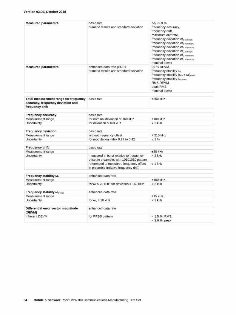
Measured parameters basic rate,
numeric results and standard deviation
Δf2 99.9 %,
frequency accuracy,
frequency drift,
maximum drift rate,
frequency deviation Δf1 average,
frequency deviation Δf1 minimum,
frequency deviation Δf1 maximum,
frequency deviation Δf2 average,
frequency deviation Δf2 minimum,
frequency deviation Δf2 maximum,
nominal power
Measured parameters enhanced data rate (EDR),
numeric results and standard deviation
99 % DEVM,
frequency stability ωi,
frequency stability (ωo + ωi)max,
frequency stability ωo max,
RMS DEVM,
peak RMS,
nominal power
Total measurement range for frequency
accuracy, frequency deviation and
frequency drift
basic rate ±250 kHz
Frequency accuracy basic rate
Measurement range for nominal deviation of 160 kHz ±100 kHz
Uncertainty for deviation ≤ 160 kHz < 2 kHz
Frequency deviation basic rate
Measurement range without frequency offset ≤ 210 kHz
Uncertainty for modulation index 0.22 to 0.42 < 1 %
Frequency drift basic rate
Measurement range ±50 kHz
Uncertainty measured in burst relative to frequency
offset in preamble, with 10101010 pattern
< 2 kHz
referenced to measured frequency offset
in preamble (relative frequency drift)
≤ 1 kHz
Frequency stability ωi enhanced data rate
Measurement range ±100 kHz
Uncertainty for ωi ≤ 75 kHz, for deviation ≤ 160 kHz < 2 kHz
Frequency stability ωo max enhanced data rate
Measurement range ±15 kHz
Uncertainty for ωo ≤ 10 kHz < 1 kHz
Differential error vector magnitude
(DEVM)
enhanced data rate
Inherent DEVM for PRBS pattern < 1.5 %, RMS;
< 3.0 %, peak
Version 03.00, October 2018
Rohde & Schwarz R&S®CMW100 Communications Manufacturing Test Set 35
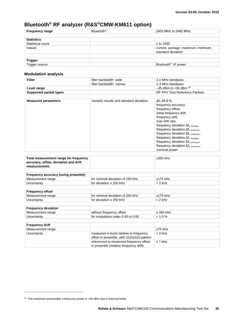
Bluetooth® RF analyzer (R&S®CMW-KM611 option) Frequency range Bluetooth® 2402 MHz to 2480 MHz
Statistics
Statistical count 1 to 1000
Values
current, average, maximum, minimum,
standard deviation
Trigger
Trigger source Bluetooth®: IF power
Modulation analysis
Filter filter bandwidth: wide 2.0 MHz bandpass
filter bandwidth: narrow 1.3 MHz bandpass
Level range –35 dBm to +36 dBm 26
Supported packet types RF PHY Test Reference Packets
Measured parameters numeric results and standard deviation Δf2 99.9 %,
frequency accuracy,
frequency offset,
initial frequency drift,
frequency drift,
max drift rate,
frequency deviation Δf1 average,
frequency deviation Δf1 minimum,
frequency deviation Δf1 maximum,
frequency deviation Δf2 average,
frequency deviation Δf2 minimum,
frequency deviation Δf2 maximum,
nominal power
Total measurement range for frequency
accuracy, offset, deviation and drift
measurements
±350 kHz
Frequency accuracy (using preamble)
Measurement range for nominal deviation of 250 kHz ±175 kHz
Uncertainty for deviation ≤ 250 kHz < 2 kHz
Frequency offset
Measurement range for nominal deviation of 250 kHz ±175 kHz
Uncertainty for deviation ≤ 250 kHz < 2 kHz
Frequency deviation
Measurement range without frequency offset ≤ 350 kHz
Uncertainty for modulation index 0.40 to 0.60 < 1.0 %
Frequency drift
Measurement range ±75 kHz
Uncertainty measured in burst relative to frequency
offset in preamble, with 10101010 pattern
< 2 kHz
referenced to measured frequency offset
in preamble (relative frequency drift)
≤ 1 kHz
26 The maximum permissible continuous power is +34 dBm due to thermal limits.

Version 03.00, October 2018
36 Rohde & Schwarz R&S®CMW100 Communications Manufacturing Test Set
Bluetooth® RF analyzer (R&S®CMW-KM721 option)
Frequency range Bluetooth® 2402 MHz to 2480 MHz
Statistics
Statistical count 1 to 1000
Values
current, average, maximum, minimum,
standard deviation
Trigger
Trigger source Bluetooth®: IF power
Modulation analysis
Filter filter bandwidth: wide (LE 2 Msymbol/s) 4.0 MHz bandpass
filter bandwidth: wide (LE long range) 2.0 MHz bandpass
filter bandwidth: narrow (LE 2 Msymbol/s) 2.6 MHz bandpass
filter bandwidth: narrow (LE long range) 1.3 MHz bandpass
Level range –35 dBm to +36 dBm 27
Supported packet types RF PHY Test Reference Packets
Measured parameters numeric results and standard deviation
(common)
frequency accuracy,
frequency offset,
initial frequency drift,
frequency drift,
max drift rate,
frequency deviation Δf1 average,
frequency deviation Δf1 minimum,
frequency deviation Δf1 maximum,
nominal power
numeric results and standard deviation
(LE 2 Msymbol/s)
Δf2 99.9 %
frequency deviation Δf2 average,
frequency deviation Δf2 minimum,
frequency deviation Δf2 maximum,
numeric results and standard deviation
(LE long range)
Δf1 99.9 %
Total measurement range for
frequency accuracy, offset, deviation
and drift measurements
LE 2 2 Msymbol/s ±700 kHz
LE long range ±350 kHz
Frequency accuracy (using preamble)
Measurement range for nominal deviation of 500 kHz
(LE 2 Msymbol/s)
±175 kHz
for nominal deviation of 250 kHz
(LE long range)
Uncertainty for deviation ≤ 500 kHz (LE 2 Msymbol/s) < 2 kHz
for deviation ≤ 250 kHz (LE long range)
Frequency offset
Measurement range for nominal deviation of 500 kHz
(LE 2 Msymbol/s)
±175 kHz
for nominal deviation of 250 kHz
(LE long range)
Uncertainty for deviation ≤ 500 kHz (LE 2 Msymbol/s) < 2 kHz
for deviation ≤ 250 kHz (LE long range)
27 The maximum permissible continuous power is +34 dBm due to thermal limits.

Version 03.00, October 2018
Rohde & Schwarz R&S®CMW100 Communications Manufacturing Test Set 37
Frequency deviation
Measurement range without frequency offset (LE 2 Msymbol/s) ≤ 700 kHz
without frequency offset (LE long range) ≤ 350 kHz
Uncertainty for modulation index 0.40 to 0.60 < 0.5 %
Frequency drift
Measurement range ±75 kHz
Uncertainty measured in burst referenced to
frequency offset in preamble
< 2 kHz
referenced to measured frequency offset
value in preamble (relative frequency drift)
≤ 1 kHz

Version 03.00, October 2018
38 Rohde & Schwarz R&S®CMW100 Communications Manufacturing Test Set
GPS specifications Standard GPS
GPS RF generator Frequency range GPS band
L1 1575.42 MHz
L2 1227.6 MHz
GPS R&S®WinIQSIM2™ (R&S®CMW-KW620 option)
Arbitrary waveform file GPS_DEFAULT.WV (PAR = 3.66 dB)
Output level range depends on PAR see general technical specifications
Output level uncertainty waveform file used:
GPS_DEFAULT.WV
see general technical specifications
Output level resolution see general technical specifications
DVB specifications Standard DVB-T
DVB RF generator Frequency range VHF band III
channels 5 to 12 174 MHz to 230 MHz
UHF band IV
channels 21 to 34 470 MHz to 582 MHz
UHF band V
channels 35 to 69 582 MHz to 862 MHz
DVB WinIQSIM2™ (R&S®CMW-KW630 option)
Arbitrary waveform file DVB-T_SCRAMBLED_16QAM_3SEC_
TESTFILE.WV (PAR = 13.23 dB)
Output level range depends on PAR see general technical specifications
Output level uncertainty waveform file used:
DVB-T_SCRAMBLED_16QAM_3SEC_
TESTFILE.WV
see general technical specifications
Output level resolution see general technical specifications
FM STEREO RADIO specifications Standard FM STEREO RADIO
FM STEREO RADIO generator Frequency range FM 70 MHz to 110 MHz
FM STEREO RADIO waveforms (R&S®CMW-KV645 option)
Arbitrary waveform file FM_M_M1K0_D75K0.WV
(PAR = 0.00 dB)
Output level range depends on PAR see general technical specifications
Output level uncertainty waveform file used:
FM_M_M1K0_D75K0.WV
see general technical specifications
Output level resolution see general technical specifications
Signal quality RMS detector *SQRT(2)
Deviation error waveform file used:
FM_M_M1K0_D75K0.WV
< 1 %
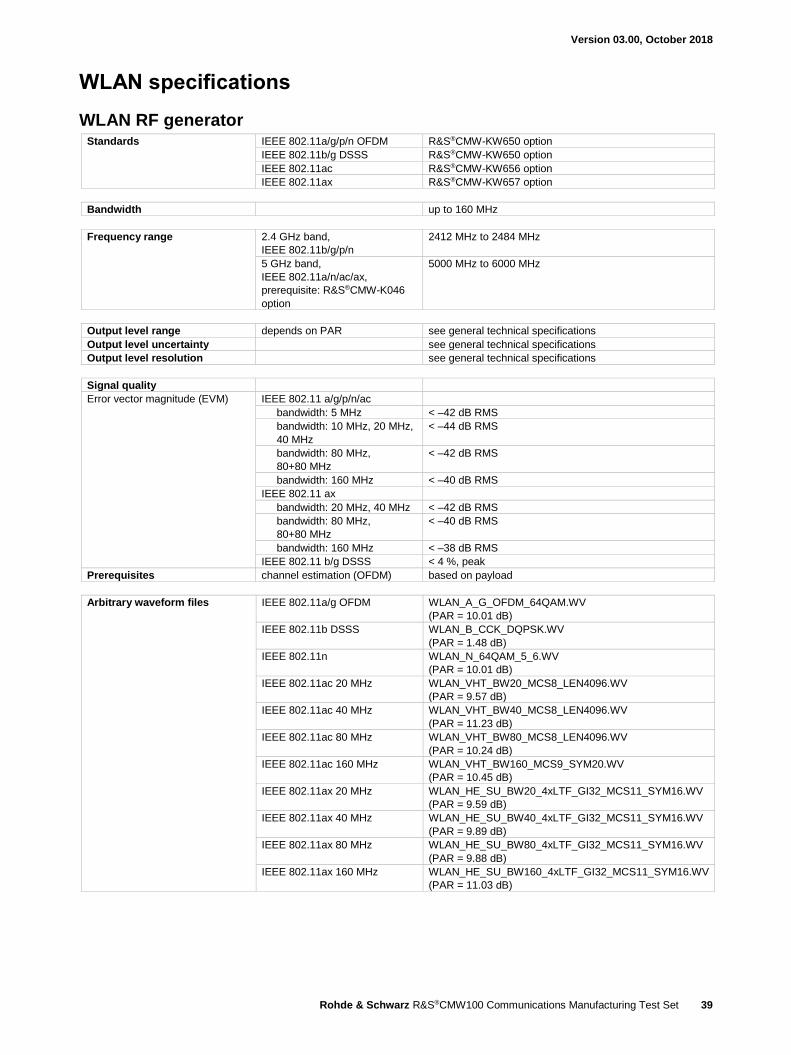
Version 03.00, October 2018
Rohde & Schwarz R&S®CMW100 Communications Manufacturing Test Set 39
WLAN specifications
WLAN RF generator Standards IEEE 802.11a/g/p/n OFDM R&S®CMW-KW650 option
IEEE 802.11b/g DSSS R&S®CMW-KW650 option
IEEE 802.11ac R&S®CMW-KW656 option
IEEE 802.11ax R&S®CMW-KW657 option
Bandwidth up to 160 MHz
Frequency range 2.4 GHz band,
IEEE 802.11b/g/p/n
2412 MHz to 2484 MHz
5 GHz band,
IEEE 802.11a/n/ac/ax,
prerequisite: R&S®CMW-K046
option
5000 MHz to 6000 MHz
Output level range depends on PAR see general technical specifications
Output level uncertainty see general technical specifications
Output level resolution see general technical specifications
Signal quality
Error vector magnitude (EVM) IEEE 802.11 a/g/p/n/ac
bandwidth: 5 MHz < –42 dB RMS
bandwidth: 10 MHz, 20 MHz,
40 MHz
< –44 dB RMS
bandwidth: 80 MHz,
80+80 MHz
< –42 dB RMS
bandwidth: 160 MHz < –40 dB RMS
IEEE 802.11 ax
bandwidth: 20 MHz, 40 MHz < –42 dB RMS
bandwidth: 80 MHz,
80+80 MHz
< –40 dB RMS
bandwidth: 160 MHz < –38 dB RMS
IEEE 802.11 b/g DSSS < 4 %, peak
Prerequisites channel estimation (OFDM) based on payload
Arbitrary waveform files IEEE 802.11a/g OFDM WLAN_A_G_OFDM_64QAM.WV
(PAR = 10.01 dB)
IEEE 802.11b DSSS WLAN_B_CCK_DQPSK.WV
(PAR = 1.48 dB)
IEEE 802.11n WLAN_N_64QAM_5_6.WV
(PAR = 10.01 dB)
IEEE 802.11ac 20 MHz WLAN_VHT_BW20_MCS8_LEN4096.WV
(PAR = 9.57 dB)
IEEE 802.11ac 40 MHz WLAN_VHT_BW40_MCS8_LEN4096.WV
(PAR = 11.23 dB)
IEEE 802.11ac 80 MHz WLAN_VHT_BW80_MCS8_LEN4096.WV
(PAR = 10.24 dB)
IEEE 802.11ac 160 MHz WLAN_VHT_BW160_MCS9_SYM20.WV
(PAR = 10.45 dB)
IEEE 802.11ax 20 MHz WLAN_HE_SU_BW20_4xLTF_GI32_MCS11_SYM16.WV
(PAR = 9.59 dB)
IEEE 802.11ax 40 MHz WLAN_HE_SU_BW40_4xLTF_GI32_MCS11_SYM16.WV
(PAR = 9.89 dB)
IEEE 802.11ax 80 MHz WLAN_HE_SU_BW80_4xLTF_GI32_MCS11_SYM16.WV
(PAR = 9.88 dB)
IEEE 802.11ax 160 MHz WLAN_HE_SU_BW160_4xLTF_GI32_MCS11_SYM16.WV
(PAR = 11.03 dB)

Version 03.00, October 2018
40 Rohde & Schwarz R&S®CMW100 Communications Manufacturing Test Set
WLAN OFDM RF analyzer Standards IEEE 802.11a/g R&S®CMW-KM650 option
IEEE 802.11n R&S®CMW-KM651 option
IEEE 802.11p R&S®CMW-KM655 option
IEEE 802.11ac R&S®CMW-KM656 option
IEEE 802.11ax R&S®CMW-KM657 option
Receive modes SISO requires above options for standards
composite MIMO R&S®CMW-KM652 option
switched MIMO R&S®CMW-KM653 option
Bandwidth IEEE 802.11a/g 20 MHz
IEEE 802.11n 20 MHz, 40 MHz
IEEE 802.11p 5 MHz, 10 MHz, 20 MHz
IEEE 802.11ac/ax 20 MHz, 40 MHz, 80 MHz, 80+80 MHz,
160 MHz
80+80 MHz can be measured
simultaneously on same or on separate
antenna ports with any channel spacing
Frequency range 2.4 GHz band,
IEEE 802.11g/p/n
2412 MHz to 2484 MHz
5 GHz band,
IEEE 802.11a/n/ac/ax,
prerequisite: R&S®CMW-K046 option
5000 MHz to 6000 MHz,
for frequency exceptions for inherent
spurious response, see general technical
specifications
Statistics
Statistical count 1 to 1000
Values current, average, maximum, minimum,
standard deviation
Trigger
Trigger sources WLAN: IF power,
BASE: external TRIG IN,
GPRF: Gen
Modulation analysis
Level range –28 dBm to +36 dBm 28
Payload length 1 to 1377 data symbols
Modulations BPSK, QPSK, 16QAM, 64QAM,
256QAM, 1024QAM
Burst types IEEE 802.11a/g/p non HT
IEEE 802.11n HT mixed-format, HT Greenfield
IEEE 802.11ac VHT mixed-format
IEEE 802.11ax HE single user (HE_SU),
HE trigger based (HE_TRIG)
HEmMultiuser (HE_MU)
MIMO switched and composite up to 8 × 8
28 The maximum permissible continuous power is +34 dBm due to thermal limits.

Version 03.00, October 2018
Rohde & Schwarz R&S®CMW100 Communications Manufacturing Test Set 41
Measured results scalar SISO results burst and signal field information,
burst power,
peak power,
crest factor,
EVM all carriers,
EVM data carriers,
EVM pilot carriers,
center frequency error,
symbol clock error,
I/Q offset,
DC power,
gain imbalance,
quadrature error
timing error
additional scalar results for 11ax EVM per user (HE_MU),
unused tone error (HE_TRIG)
graphical SISO results EVM versus symbol,
EVM versus carrier,
I/Q constellation,
spectrum flatness,
power versus time
additional graphical results for 11ax EVM versus user (HE_MU),
unused tone error (HE_TRIG)
switched MIMO results same as SISO results,
SISO results per antenna or stream
composite MIMO results EVM all carriers,
EVM data carriers,
EVM pilot carriers,
total power,
total peak power,
power per space time stream,
center frequency error
symbol clock error
Error vector magnitude (EVM)
Inherent EVM (RMS) IEEE 802.11 a/g/p/n/ac
bandwidth: 5 MHz < –44 dB
bandwidth: 10 MHz, 20 MHz, 40 MHz < –46 dB
bandwidth: 80 MHz, 80+80 MHz < –44 dB
bandwidth: 160 MHz < –42 dB
IEEE 802.11 ax
bandwidth: 20 MHz, 40 MHz < –44 dB
bandwidth: 80 MHz, 80+80 MHz < –42 dB
bandwidth: 160 MHz < –40 dB
Prerequisites expected nominal power setting ≥ –8 dBm for 2.4 GHz band
≥ +2 dBm for 5 GHz band
channel estimation based on payload
burst length > 16 symbols
average > 20 packets
Center frequency error
Frequency measurement uncertainty 2.4 GHz band < 20 Hz + drift of timebase,
see general technical specifications
5 GHz band < 35 Hz + drift of timebase,
see general technical specifications
Prerequisites measurement length ≥ 100 symbols
Symbol clock error
Uncertainty < 1 ppm
I/Q offset
Inherent I/Q offset for average ≥ 10 measurements < –45 dB
Spectrum flatness
Level uncertainty bandwidth: 5 MHz, 10 MHz, 20 MHz ≤ 0.8 dB
bandwidth: 40 MHz, 80 MHz, 160 MHz ≤ 1.0 dB

Version 03.00, October 2018
42 Rohde & Schwarz R&S®CMW100 Communications Manufacturing Test Set
Spectrum measurements
Transmit spectrum mask
Frequency span 4 × of used WLAN bandwidth 40 MHz to 640 MHz
Limit masks IEEE, ETSI, ARIB
Resolution bandwidth IEEE, ARIB 100 kHz
ETSI 1 MHz
Dynamic range in line with IEEE standard
Expected nominal power setting for full dynamic range
2.4 GHz band +2 dBm to +42 dBm 29
5 GHz band +12 dBm to +42 dBm 29
WLAN DSSS RF analyzer Standards IEEE 802.11b/g R&S®CMW-KM650 option
Frequency range 2.4 GHz band 2412 MHz to 2484 MHz
Statistics
Statistical count 1 to 1000
Values current, average, maximum,
standard deviation
Trigger
Trigger sources WLAN: IF power,
BASE: external TRIG IN,
GPRF: Gen
Modulation analysis
Level range –28 dBm to +36 dBm 29
Payload length 1000 to 362472 chips
Modulations 1 Mbps DBPSK,
2 Mbps DQPSK,
5.5 Mbps CCK,
11 Mbps CCK
Measured parameters scalar results burst and signal field information,
burst power,
EVM peak,
EVM RMS,
center frequency error,
chip clock error,
I/Q offset,
gain imbalance,
quadrature error,
rise/fall time
graphical results EVM versus chip,
I/Q constellation,
power versus time
Error vector magnitude (EVM)
Inherent EVM < 5 %, peak
< 2 %, RMS
Prerequisites input level –18 dBm ≤ input level ≤ +36 dBm 30, RMS
measurement length 1000 chips
Center frequency error
Frequency measurement uncertainty < 20 Hz + drift of timebase,
see general technical specifications
Chip clock error
Uncertainty < 1 ppm
I/Q offset
Inherent I/Q offset OFDM, for average ≥ 10 measurements < –45 dB
29 The maximum permissible continuous power is +34 dBm due to thermal limits.

Version 03.00, October 2018
Rohde & Schwarz R&S®CMW100 Communications Manufacturing Test Set 43
Spectrum measurements
Transmit spectrum mask
Frequency span 80 MHz
Resolution bandwidth IEEE 100 kHz
Dynamic range in line with IEEE standard
Limit masks IEEE
Expected nominal power setting for full dynamic range
+2 dBm to +42 dBm 30
30 The maximum permissible continuous power is +34 dBm due to thermal limits.
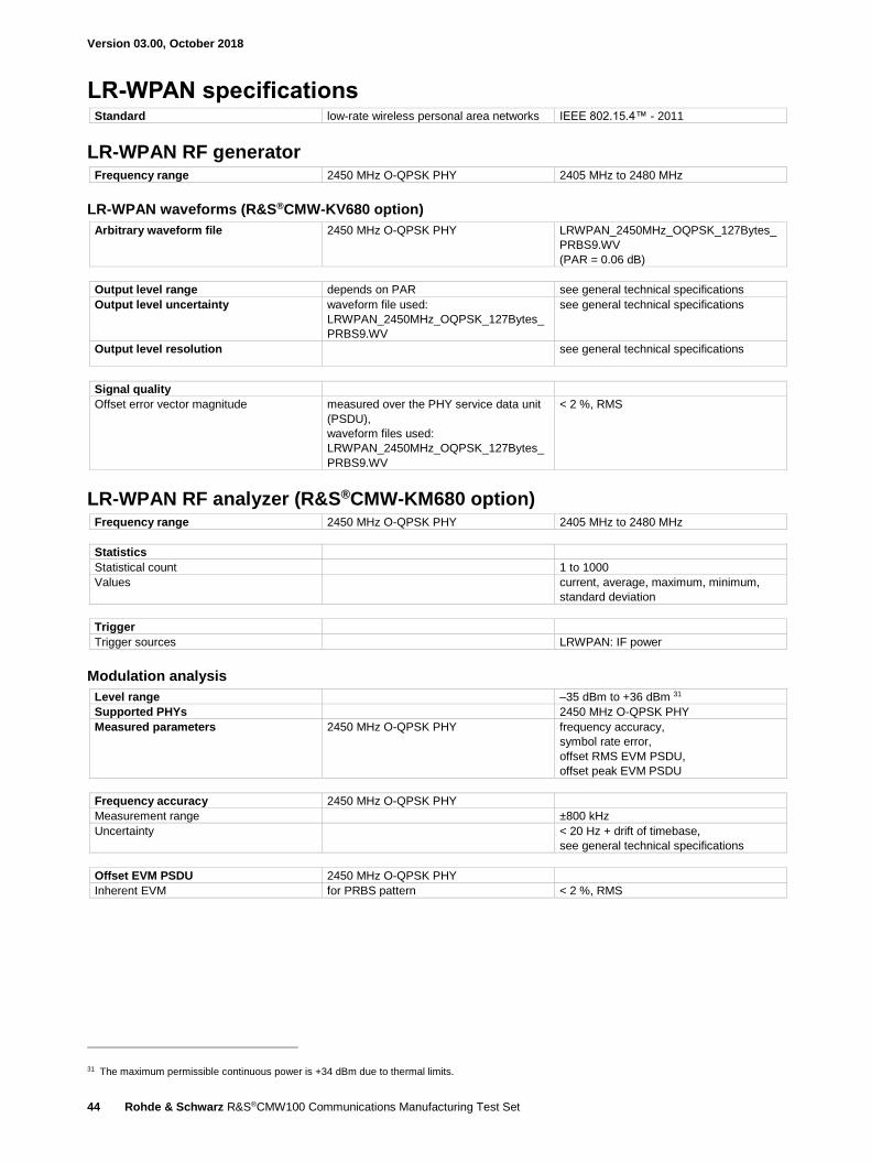
Version 03.00, October 2018
44 Rohde & Schwarz R&S®CMW100 Communications Manufacturing Test Set
LR-WPAN specifications Standard low-rate wireless personal area networks IEEE 802.15.4™ - 2011
LR-WPAN RF generator Frequency range 2450 MHz O-QPSK PHY 2405 MHz to 2480 MHz
LR-WPAN waveforms (R&S®CMW-KV680 option)
Arbitrary waveform file 2450 MHz O-QPSK PHY LRWPAN_2450MHz_OQPSK_127Bytes_
PRBS9.WV
(PAR = 0.06 dB)
Output level range depends on PAR see general technical specifications
Output level uncertainty waveform file used:
LRWPAN_2450MHz_OQPSK_127Bytes_
PRBS9.WV
see general technical specifications
Output level resolution see general technical specifications
Signal quality
Offset error vector magnitude measured over the PHY service data unit
(PSDU),
waveform files used:
LRWPAN_2450MHz_OQPSK_127Bytes_
PRBS9.WV
< 2 %, RMS
LR-WPAN RF analyzer (R&S®CMW-KM680 option) Frequency range 2450 MHz O-QPSK PHY 2405 MHz to 2480 MHz
Statistics
Statistical count 1 to 1000
Values
current, average, maximum, minimum,
standard deviation
Trigger
Trigger sources LRWPAN: IF power
Modulation analysis
Level range –35 dBm to +36 dBm 31
Supported PHYs 2450 MHz O-QPSK PHY
Measured parameters 2450 MHz O-QPSK PHY frequency accuracy,
symbol rate error,
offset RMS EVM PSDU,
offset peak EVM PSDU
Frequency accuracy 2450 MHz O-QPSK PHY
Measurement range ±800 kHz
Uncertainty < 20 Hz + drift of timebase,
see general technical specifications
Offset EVM PSDU 2450 MHz O-QPSK PHY
Inherent EVM for PRBS pattern < 2 %, RMS
31 The maximum permissible continuous power is +34 dBm due to thermal limits.

Version 03.00, October 2018
Rohde & Schwarz R&S®CMW100 Communications Manufacturing Test Set 45
TD-SCDMA specifications – mobile station (UE) test Standard TD-SCDMA CWTS
TD-SCDMA RF generator Frequency range 32 TD-SCDMA band A
channels 10054 to 10121 2010.8 MHz to 2024.2 MHz
TD-SCDMA band E
channels 11504 to 11996 2300.8 MHz to 2399.2 MHz
TD-SCDMA band F
channels 9404 to 9596 1880.8 MHz to 1919.2 MHz
TD-SCDMA R&S®WinIQSIM2™ (R&S®CMW-KW750 option) and
TD-SCDMA Enhanced R&S®WinIQSIM2™ (R&S®CMW-KW751 option)
Arbitrary waveform files with the R&S®CMW-KW750 option TD-SCDMA_DEFAULT.WV
(PAR = 3.14 dB),
TD-SCDMA_PTWLOW.WV
(PAR = 2.67 dB)
with the R&S®CMW-KW750 and
R&S®CMW-KW751 options
TD-SCDMA-DL_12K2.WV
(PAR = 5.41 dB)
Output level range depends on PAR see general technical specifications
Output level uncertainty waveform file used:
TD-SCDMA_PTWLOW.WV
see general technical specifications
Output level resolution see general technical specifications
Signal quality
Error vector magnitude (EVM) composite EVM,
waveform file used:
TD-SCDMA_DEFAULT.WV
< 4 %, RMS
TD-SCDMA RF analyzer (R&S®CMW-KM750 option) Frequency range 32 TD-SCDMA band A
channels 10054 to 10121 2010.8 MHz to 2024.2 MHz
TD-SCDMA band E
channels 11504 to 11996 2300.8 MHz to 2399.2 MHz
TD-SCDMA band F
channels 9404 to 9596 1880.8 MHz to 1919.2 MHz
Statistics
Statistical count 1 to 1000
Values current, average, minimum/maximum,
standard deviation
Trigger
Trigger sources BASE: external TRIG IN
GPRF: Gen
TD-SCDMA: free run
TD-SCDMA: IF power
Modulation analysis
Filter
1.28 MHz, RRC, α = 0.22, TD-SCDMA
filter
Level range –28 dBm to +36 dBm 33
Analysis modes TD-SCDMA uplink QPSK, DPCH,
QPSK, DPCH + HSDPA,
16QAM, DPCH + HSUPA
32 Bands A, E, F in line with the CCSA standard.
33 The maximum permissible continuous power is +34 dBm due to thermal limits.
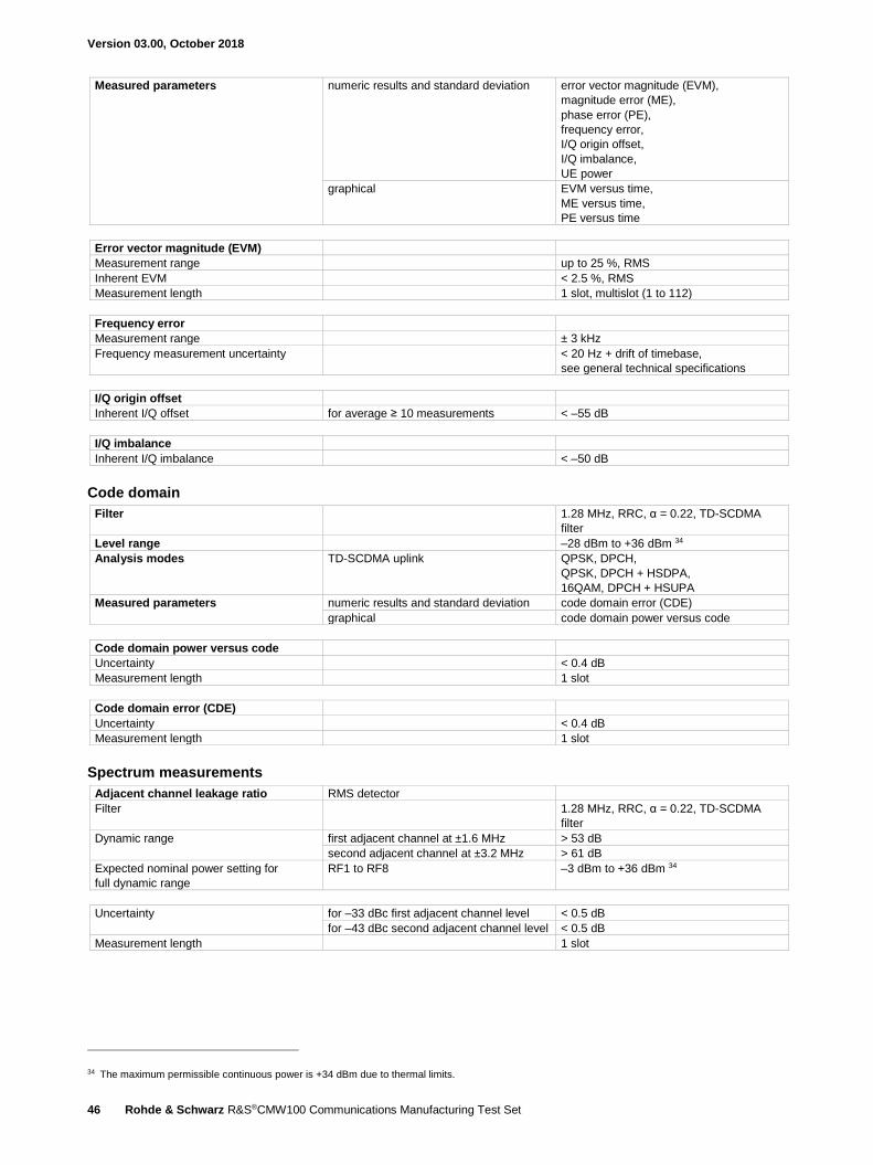
Version 03.00, October 2018
46 Rohde & Schwarz R&S®CMW100 Communications Manufacturing Test Set
Measured parameters numeric results and standard deviation error vector magnitude (EVM),
magnitude error (ME),
phase error (PE),
frequency error,
I/Q origin offset,
I/Q imbalance,
UE power
graphical EVM versus time,
ME versus time,
PE versus time
Error vector magnitude (EVM)
Measurement range up to 25 %, RMS
Inherent EVM < 2.5 %, RMS
Measurement length 1 slot, multislot (1 to 112)
Frequency error
Measurement range ± 3 kHz
Frequency measurement uncertainty < 20 Hz + drift of timebase,
see general technical specifications
I/Q origin offset
Inherent I/Q offset for average ≥ 10 measurements < –55 dB
I/Q imbalance
Inherent I/Q imbalance < –50 dB
Code domain
Filter
1.28 MHz, RRC, α = 0.22, TD-SCDMA
filter
Level range –28 dBm to +36 dBm 34
Analysis modes TD-SCDMA uplink QPSK, DPCH,
QPSK, DPCH + HSDPA,
16QAM, DPCH + HSUPA
Measured parameters numeric results and standard deviation code domain error (CDE)
graphical code domain power versus code
Code domain power versus code
Uncertainty < 0.4 dB
Measurement length 1 slot
Code domain error (CDE)
Uncertainty < 0.4 dB
Measurement length 1 slot
Spectrum measurements
Adjacent channel leakage ratio RMS detector
Filter
1.28 MHz, RRC, α = 0.22, TD-SCDMA
filter
Dynamic range first adjacent channel at ±1.6 MHz > 53 dB
second adjacent channel at ±3.2 MHz > 61 dB
Expected nominal power setting for
full dynamic range
RF1 to RF8 –3 dBm to +36 dBm 34
Uncertainty for –33 dBc first adjacent channel level < 0.5 dB
for –43 dBc second adjacent channel level < 0.5 dB
Measurement length 1 slot
34 The maximum permissible continuous power is +34 dBm due to thermal limits.
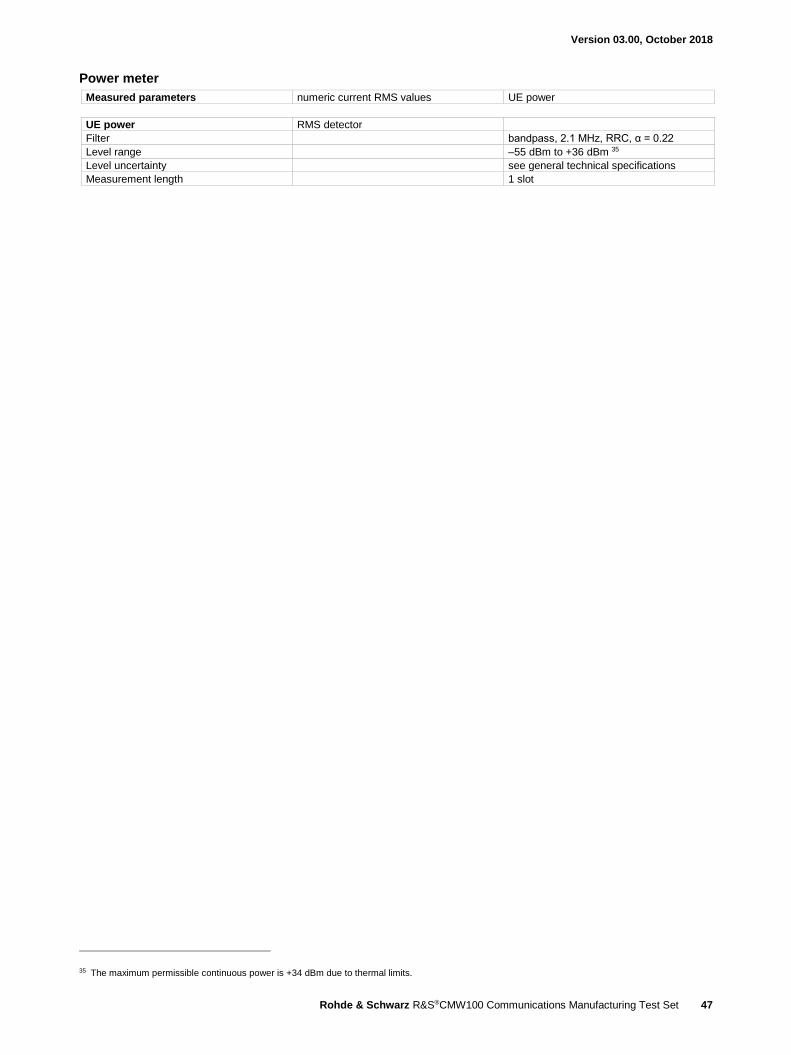
Version 03.00, October 2018
Rohde & Schwarz R&S®CMW100 Communications Manufacturing Test Set 47
Power meter
Measured parameters numeric current RMS values UE power
UE power RMS detector
Filter bandpass, 2.1 MHz, RRC, α = 0.22
Level range –55 dBm to +36 dBm 35
Level uncertainty see general technical specifications
Measurement length 1 slot
35 The maximum permissible continuous power is +34 dBm due to thermal limits.

Version 03.00, October 2018
48 Rohde & Schwarz R&S®CMW100 Communications Manufacturing Test Set
CDMA2000® 1xRTT specifications – mobile station test Standard CDMA2000® standards TIA/EIA IS-2000 Rev. 0
CDMA2000® test standards TIA/EIA IS-98-F
Symbol rate 1.2288 Mcps
CDMA2000® 1xRTT RF generator Frequency range band class 0 860.025 MHz to 893.985 MHz
band class 1 1930.000 MHz to 1990.000 MHz
band class 2 917.0125 MHz to 959.9875 MHz
band class 3 832.0125 MHz to 869.9875 MHz
band class 4 1840.000 MHz to 1870.000 MHz
band class 5 421.675 MHz to 493.480 MHz
band class 6 2110.000 MHz to 2169.950 MHz
band class 7 746.000 MHz to 764.000 MHz
band class 8 1805.000 MHz to 1879.950 MHz
band class 9 925.000 MHz to 958.750 MHz
band class 10 851.000 MHz to 939.975 MHz
band class 11 421.675 MHz to 493.475 MHz
band class 12 915.0125 MHz to 920.9875 MHz
band class 13 2620.000 MHz to 2690 MHz
band class 14 1930.000 MHz to 1995.000 MHz
band class 15 2110.000 MHz to 2155.000 MHz
band class 16 2624.000 MHz to 2690.000 MHz
band class 17 2624.000 MHz to 2690.000 MHz
band class 18 757.000 MHz to 769.000 MHz
band class 19 728.000 MHz to 746.000 MHz
band class 20 1525.000 MHz to 1559.000 MHz
band class 21 2190.000 MHz to 2200.000 MHz
CDMA2000® R&S®WinIQSIM2™ (R&S®CMW-KW800 option)
Arbitrary waveform files CDMA_OQPSK.WV (PAR = 5.54 dB) or
CDMA_HPSK.WV (PAR = 6.97 dB)
Output level range depends on PAR see general technical specifications
Output level uncertainty waveform file used:
CDMA_OQPSK.WV or CDMA_HPSK.WV
see general technical specifications
Output level resolution see general technical specifications
Signal quality
Waveform quality (rho) waveform file used:
CDMA_OQPSK.WV or CDMA_HPSK.WV
> 0.99

Version 03.00, October 2018
Rohde & Schwarz R&S®CMW100 Communications Manufacturing Test Set 49
CDMA2000® RF analyzer (R&S®CMW-KM800 option) Frequency range band class 0 815.025 MHz to 848.985 MHz
band class 1 1850.000 MHz to 1910.000 MHz
band class 2 872.0125 MHz to 914.9875 MHz
band class 3 887.0125 MHz to 924.9875 MHz
band class 4 1750.000 MHz to 1780.000 MHz
band class 5 411.675 MHz to 483.480 MHz
band class 6 1920.000 MHz to 1979.950 MHz
band class 7 776.000 MHz to 794.000 MHz
band class 8 1710.000 MHz to 1784.950 MHz
band class 9 880.000 MHz to 913.750 MHz
band class 10 806.000 MHz to 900.975 MHz
band class 11 411.675 MHz to 483.475 MHz
band class 12 870.0125 MHz to 875.9875 MHz
band class 13 2500.000 MHz to 2570.000 MHz
band class 14 1850.000 MHz to 1915.000 MHz
band class 15 1710.000 MHz to 1755.000 MHz
band class 16 2502.000 MHz to 2568.000 MHz
band class 17 2502.000 MHz to 2567.950 MHz
band class 18 787.000 MHz to 700.000 MHz
band class 19 698.000 MHz to 716.000 MHz
band class 20 1626.500 MHz to 1660.500 MHz
band class 21 2000.000 MHz to 2029.950 MHz
Statistics
Statistical count 1 to 1000
Values current, average, minimum/maximum,
standard deviation
Trigger
Trigger sources BASE: external TRIG IN
GPRF: Gen
C2K: free run
CDMA2000® signaling:
superframe (80 ms)
Modulation analysis
Filter 1.23 MHz, RRC, α = 0.22, CDMA filter
Level range –28 dBm to +36 dBm 36
Analysis modes OQPSK, HPSK
Measured parameters numeric results and standard deviation error vector magnitude (EVM),
magnitude error (ME),
phase error (PE),
frequency error,
rho,
carrier feedthrough,
I/Q imbalance,
power,
wideband power (8 MHz),
narrowband power (1.23 MHz)
graphical EVM versus time,
ME versus time,
PE versus time
Waveform quality (rho)
Uncertainty for rho 0.9 to 1 < 0.003
Measurement length 616 chip (0.5 ms)
Error vector magnitude (EVM)
Measurement range up to 25 %, RMS
Inherent EVM < 2.5 %, RMS
Measurement length 0.5 ms
36 The maximum permissible continuous power is +34 dBm due to thermal limits.
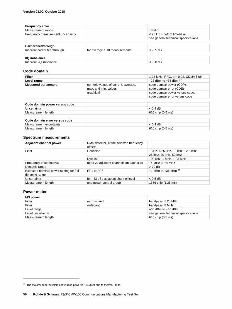
Version 03.00, October 2018
50 Rohde & Schwarz R&S®CMW100 Communications Manufacturing Test Set
Frequency error
Measurement range 3 kHz
Frequency measurement uncertainty < 20 Hz + drift of timebase,
see general technical specifications
Carrier feedthrough
Inherent carrier feedthrough for average ≥ 10 measurements < –55 dB
I/Q imbalance
Inherent I/Q imbalance < –50 dB
Code domain
Filter 1.23 MHz, RRC, α = 0.22, CDMA filter
Level range –28 dBm to +36 dBm 37
Measured parameters numeric values of current, average,
max. and min. values
code domain power (CDP),
code domain error (CDE)
graphical code domain power versus code,
code domain error versus code
Code domain power versus code
Uncertainty < 0.4 dB
Measurement length 616 chip (0.5 ms)
Code domain error versus code
Measurement uncertainty < 0.4 dB
Measurement length 616 chip (0.5 ms)
Spectrum measurements
Adjacent channel power RMS detector, at the selected frequency
offsets
Filter Gaussian 1 kHz, 6.25 kHz, 10 kHz, 12.5 kHz,
25 kHz, 30 kHz, 50 kHz Nyquist 100 kHz, 1 MHz, 1.23 MHz
Frequency offset interval up to 20 adjacent channels on each side –4 MHz to +4 MHz
Dynamic range > 70 dB
Expected nominal power setting for full
dynamic range
RF1 to RF8 +1 dBm to +36 dBm 37
Uncertainty for –43 dBc adjacent channel level < 0.5 dB
Measurement length one power control group 1536 chip (1.25 ms)
Power meter
MS power
Filter narrowband bandpass, 1.25 MHz
Filter wideband bandpass, 8 MHz
Level range –55 dBm to +36 dBm 37
Level uncertainty see general technical specifications
Measurement length 616 chip (0.5 ms)
37 The maximum permissible continuous power is +34 dBm due to thermal limits.
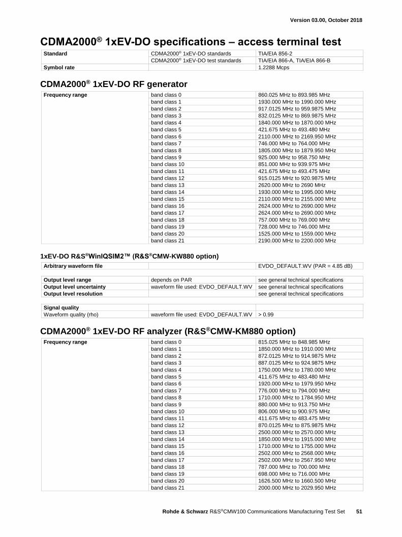
Version 03.00, October 2018
Rohde & Schwarz R&S®CMW100 Communications Manufacturing Test Set 51
CDMA2000® 1xEV-DO specifications – access terminal test Standard CDMA2000® 1xEV-DO standards TIA/EIA 856-2
CDMA2000® 1xEV-DO test standards TIA/EIA 866-A, TIA/EIA 866-B
Symbol rate 1.2288 Mcps
CDMA2000® 1xEV-DO RF generator Frequency range band class 0 860.025 MHz to 893.985 MHz
band class 1 1930.000 MHz to 1990.000 MHz
band class 2 917.0125 MHz to 959.9875 MHz
band class 3 832.0125 MHz to 869.9875 MHz
band class 4 1840.000 MHz to 1870.000 MHz
band class 5 421.675 MHz to 493.480 MHz
band class 6 2110.000 MHz to 2169.950 MHz
band class 7 746.000 MHz to 764.000 MHz
band class 8 1805.000 MHz to 1879.950 MHz
band class 9 925.000 MHz to 958.750 MHz
band class 10 851.000 MHz to 939.975 MHz
band class 11 421.675 MHz to 493.475 MHz
band class 12 915.0125 MHz to 920.9875 MHz
band class 13 2620.000 MHz to 2690 MHz
band class 14 1930.000 MHz to 1995.000 MHz
band class 15 2110.000 MHz to 2155.000 MHz
band class 16 2624.000 MHz to 2690.000 MHz
band class 17 2624.000 MHz to 2690.000 MHz
band class 18 757.000 MHz to 769.000 MHz
band class 19 728.000 MHz to 746.000 MHz
band class 20 1525.000 MHz to 1559.000 MHz
band class 21 2190.000 MHz to 2200.000 MHz
1xEV-DO R&S®WinIQSIM2™ (R&S®CMW-KW880 option)
Arbitrary waveform file EVDO_DEFAULT.WV (PAR = 4.85 dB)
Output level range depends on PAR see general technical specifications
Output level uncertainty waveform file used: EVDO_DEFAULT.WV see general technical specifications
Output level resolution see general technical specifications
Signal quality
Waveform quality (rho) waveform file used: EVDO_DEFAULT.WV > 0.99
CDMA2000® 1xEV-DO RF analyzer (R&S®CMW-KM880 option) Frequency range band class 0 815.025 MHz to 848.985 MHz
band class 1 1850.000 MHz to 1910.000 MHz
band class 2 872.0125 MHz to 914.9875 MHz
band class 3 887.0125 MHz to 924.9875 MHz
band class 4 1750.000 MHz to 1780.000 MHz
band class 5 411.675 MHz to 483.480 MHz
band class 6 1920.000 MHz to 1979.950 MHz
band class 7 776.000 MHz to 794.000 MHz
band class 8 1710.000 MHz to 1784.950 MHz
band class 9 880.000 MHz to 913.750 MHz
band class 10 806.000 MHz to 900.975 MHz
band class 11 411.675 MHz to 483.475 MHz
band class 12 870.0125 MHz to 875.9875 MHz
band class 13 2500.000 MHz to 2570.000 MHz
band class 14 1850.000 MHz to 1915.000 MHz
band class 15 1710.000 MHz to 1755.000 MHz
band class 16 2502.000 MHz to 2568.000 MHz
band class 17 2502.000 MHz to 2567.950 MHz
band class 18 787.000 MHz to 700.000 MHz
band class 19 698.000 MHz to 716.000 MHz
band class 20 1626.500 MHz to 1660.500 MHz
band class 21 2000.000 MHz to 2029.950 MHz

Version 03.00, October 2018
52 Rohde & Schwarz R&S®CMW100 Communications Manufacturing Test Set
Statistics
Statistical count 1 to 1000
Values current, average, minimum/maximum,
standard deviation
Trigger
Trigger sources BASE: external TRIG IN
GPRF: Gen
1xEV-DO: free run
1xEV-DO signaling:
superframe (80 ms)
Modulation analysis
Filter 1.23 MHz, RRC, α = 0.22, CDMA filter
Level range –28 dBm to +36 dBm 38
Analysis modes dual BPSK
Multicarrier single carrier or 3 carriers within –8 MHz
to +8 MHz
Measured parameters numeric results and standard deviation error vector magnitude (EVM),
magnitude error (ME),
phase error (PE),
frequency error,
rho,
carrier feedthrough,
I/Q imbalance,
power,
wideband power (8 MHz for single carrier
or 16 MHz for multicarrier),
narrowband power (1.23 MHz)
graphical EVM versus time,
ME versus time,
PE versus time
Waveform quality (rho)
Uncertainty for rho 0.9 to 1 < 0.003
Measurement length half-slot 1024 chip (833.33 µs)
Error vector magnitude (EVM)
Measurement range up to 25 %, RMS
Inherent EVM < 2.5 %, RMS
Measurement length half-slot 1024 chip (833.33 µs)
Frequency error
Measurement range ±3 kHz
Frequency measurement uncertainty < 20 Hz + drift of timebase,
see general technical specifications
Carrier feedthrough
Inherent carrier feedthrough for average ≥ 10 measurements < –55 dB
I/Q imbalance
Inherent I/Q imbalance < –50 dB
38 The maximum permissible continuous power is +34 dBm due to thermal limits.
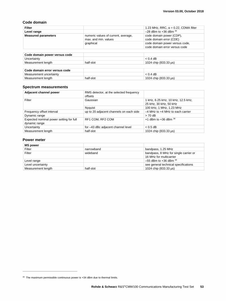
Version 03.00, October 2018
Rohde & Schwarz R&S®CMW100 Communications Manufacturing Test Set 53
Code domain
Filter 1.23 MHz, RRC, α = 0.22, CDMA filter
Level range –28 dBm to +36 dBm 39
Measured parameters numeric values of current, average,
max. and min. values
code domain power (CDP),
code domain error (CDE)
graphical code domain power versus code,
code domain error versus code
Code domain power versus code
Uncertainty < 0.4 dB
Measurement length half-slot 1024 chip (833.33 µs)
Code domain error versus code
Measurement uncertainty < 0.4 dB
Measurement length half-slot 1024 chip (833.33 µs)
Spectrum measurements
Adjacent channel power RMS detector, at the selected frequency
offsets
Filter Gaussian 1 kHz, 6.25 kHz, 10 kHz, 12.5 kHz,
25 kHz, 30 kHz, 50 kHz Nyquist 100 kHz, 1 MHz, 1.23 MHz
Frequency offset interval up to 20 adjacent channels on each side –4 MHz to +4 MHz to each carrier
Dynamic range > 70 dB
Expected nominal power setting for full
dynamic range
RF1 COM, RF2 COM +1 dBm to +36 dBm 39
Uncertainty for –43 dBc adjacent channel level < 0.5 dB
Measurement length half-slot 1024 chip (833.33 µs)
Power meter
MS power
Filter narrowband bandpass, 1.25 MHz
Filter wideband bandpass, 8 MHz for single carrier or
16 MHz for multicarrier
Level range –55 dBm to +36 dBm 39
Level uncertainty see general technical specifications
Measurement length half-slot 1024 chip (833.33 µs)
39 The maximum permissible continuous power is +34 dBm due to thermal limits.

Version 03.00, October 2018
54 Rohde & Schwarz R&S®CMW100 Communications Manufacturing Test Set
NR specifications – mobile station test Standard NR Sub-6GHz
NR sub 6G RF analyzer (R&S®CMW-KM6000 option) Bandwidth 5MHz, 10MHz, 15MHz, 20MHz, 25MHz,
40MHz, 50MHz, 60MHz,80MHz,100MHz
Frequency range NR band n1, FDD 1920 MHz to 1980 MHz
NR band n2, FDD 1850 MHz to 1910 MHz
NR band n3, FDD 1710 MHz to 1785 MHz
NR band n5, FDD 824 MHz to 849 MHz
NR band n7, FDD 2500 MHz to 2570 MHz
NR band n8, FDD 880 MHz to 915 MHz
NR band n20, FDD 832 MHz to 862 MHz
NR band n28, FDD 703 MHz to 748 MHz
NR band n38, TDD 2570 MHz to 2620 MHz
NR band n41, TDD 2496 MHz to 2690 MHz
NR band n50, TDD 1432 MHz to 1517 MHz
NR band n51, TDD 1427 MHz to 1432 MHz
NR band n66, FDD 1710 MHz to 1780 MHz
NR band n70, FDD 1695 MHz to 1710 MHz
NR band n71, FDD 663 MHz to 698 MHz
NR band n74, FDD 1427 MHz to 1470 MHz
NR band n77, TDD 3300 MHz to 4200 MHz
NR band n78, TDD 3300 MHz to 3800 MHz
NR band n79, TDD 4400 MHz to 5000 MHz
NR band n80, SUL 1710 MHz to 1785 MHz
NR band n81, SUL 880 MHz to 915 MHz
NR band n82, SUL 832 MHz to 862 MHz
NR band n83, SUL 703 MHz to 748 MHz
NR band n84, SUL 1920 MHz to 1980 MHz
Statistics
Statistical count 1 to 1000
Values current, average, minimum/maximum,
standard deviation
Trigger
Trigger sources BASE: external TRIG IN
GPRF: Gen
NR: free run (fast sync)
NR: IF power
Power measurement
Slot power RMS detector
Level range –50 dBm to +30 dBm, RMS
Level uncertainty see general technical specifications
Modulation analysis
Measured parameters numeric results error vector magnitude (EVM),
magnitude error (ME),
phase error (PE),
frequency error,
I/Q origin offset,
TX power,
peak power,
resource block power (RB power)
graphical EVM vs OFDM symbol,
ME vs OFDM symbol,
PE vs OFDM symbol,
EVM vs Subcarrier,
Inband Emissions,
Equalizer Spectrum Flatness,
I/Q Constellation

Version 03.00, October 2018
Rohde & Schwarz R&S®CMW100 Communications Manufacturing Test Set 55
Error vector magnitude (EVM)
Inherent EVM transmission bandwidth ≤ 25 MHz
–31 dBm ≤ input level < +30 dBm, RMS < 1 %, RMS
–39 dBm ≤ input level < –31 dBm, RMS < 2 %, RMS
transmission bandwidth ≤ 50 MHz
–28 dBm ≤ input level ≤ +30 dBm, RMS < 1 %, RMS
–36 dBm ≤ input level < –28 dBm, RMS < 2 %, RMS
transmission bandwidth ≤ 100 MHz
–25 dBm ≤ input level ≤ +30 dBm, RMS < 1 %, RMS
–33 dBm ≤ input level < –25 dBm, RMS < 2 %, RMS
Frequency error
Measurement range ±80 kHz
Frequency measurement uncertainty < 3.3 GHz < 20 Hz + drift of timebase,
see general technical specifications
< 6 GHz < 35 Hz + drift of timebase,
see general technical specifications
I/Q origin offset
Inherent I/Q offset for average ≥ 10 measurements < – 50 dBc
In-band emissions
Dynamic range transmission bandwidth ≤ 50% > 40 dB
Expected nominal power setting for
full dynamic range
RF1 to RF8 see general technical specifications
Equalizer spectrum flatness
Level uncertainty transmission bandwidth ≤ 100MHz < 1 dB
Spectrum measurements
Adjacent channel leakage ratio
Filter NR rectangle filters
4.515 MHz, 9.375 MHz, 14.235 MHz,
19.095 MHz, 23.955 MHz, 38.895 MHz,
48.615 MHz, 58.35 MHz, 78.15 MHz,
98.31 MHz
UTRA 3.84 MHz, RRC, α = 0.22, WCDMA filter
Dynamic range NR > 38 dB
UTRA > 50 dB
Expected nominal power setting for full
dynamic range
RF1 to RF8 see general technical specifications
Spectrum emission mask (SEM)
Frequency span 100 MHz channel bandwidth 310 MHz
Noise floor RBW: 1 MHz < –35 dBm
RBW: 30 kHz < –45 dBm

Version 03.00, October 2018
56 Rohde & Schwarz R&S®CMW100 Communications Manufacturing Test Set
General data RF connectors (front panel) SnapN female, 50 Ω, compatible with
N female connectors
RF 1 TO RF 8 combined RF input and RF output
TX AUX RF output
Control interface (rear panel)
USB max. length 3 m USB 3.0 type B connector
Trigger interface (rear panel) trigger input/output 2 × BNC connector
output trigger sources standard-specific internal trigger sources
Power input (rear panel) For safety reasons, the instrument is only
to be used with the Rohde & Schwarz
AC adapter (order no. 1210.7812.00).
DC socket
Rated voltage 24 V DC (± 10 %)
Rated current max. 5 A
Power consumption max. 80 W
Environmental conditions
Temperature operating temperature range +5 °C to +45 °C
storage temperature range –25 °C to +60 °C
Damp heat +40 °C, 80 % rel. humidity, steady state,
in line with EN 600068-2-78
Product conformity
Electromagnetic compatibility EU: in line with EMC Directive
2014/30/EC
applied harmonized standards:
EN 61326-1 (industrial environment)
EN 61326-2-1
EN 55011 (class A)
Electrical safety EU applied harmonized standard:
EN 61010-1
USA/Canada applied harmonized standards:
UL 61010-1
CAN C22.2 No. 61010-1
RoHS EU: in line with Directive 2011/65/EC on
the restriction of the use of certain
hazardous substances in electrical and
electronic equipment
EN 50581
Mechanical resistance nonoperating mode
Vibration sinusoidal 5 Hz to 55 Hz, 0.3 mm double amplitude
const.,
55 Hz to 150 Hz, 0.5 g const.,
in line with EN 60068-2-6
Vibration random 10 Hz to 300 Hz, acceleration 1.2 g RMS,
in line with EN 60068-2-64
Shock 40 g shock spectrum,
in line with MIL-STD-810, method 516,
procedure I
Dimensions W × H × D, overall 354 mm × 112 mm × 394 mm
(14.0 in × 4.4 in × 15.5 in)
Weight approx. 6.8 kg (15 lb)
Calibration interval 12 months recommended for highest accuracy,
see specified RF generator and
RF analyzer level uncertainty
24 months add 0.2 dB to specified RF generator and
RF analyzer level uncertainty

Version 03.00, October 2018
Rohde & Schwarz R&S®CMW100 Communications Manufacturing Test Set 57
Accessories delivered with R&S®CMW-PS16 (1210.7629.03)
External Rohde & Schwarz AC adapter (1210.7812.00) The external Rohde & Schwarz AC adapter is required to connect the R&S®CMW100 to AC mains.
Power rating
Rated voltage 100 V to 240 V AC (±10 %)
Rated frequency 50 Hz to 60 Hz (±5 %)
Rated current max. 1.4 A
Output voltage 24 V DC (±3 %)
Output current max. 5 A
Power consumption with R&S®CMW100 load see general data
with no load approx. 0.15 W
Environmental conditions
Temperature operating temperature range see general data
storage temperature range see general data
Damp heat see general data
Product conformity
Electromagnetic compatibility EU: in line with EMC Directive 2014/30/EC applied harmonized standards:
EN 61000
EN 55032 class B
Electrical safety EU: in line with Low Voltage Directive
2014/35/EC
applied harmonized standard:
EN 60950-1
USA/Canada/Japan applied standards:
UL/CAN/CSA-C22.2 No. 60950-1
J60950-1
Korea applied standard:
Korea KC
Dimensions W × H × D, overall 167 mm × 67 mm × 35 mm
(6.57 in × 2.64 in × 1.38 in)
Weight approx. 0.62 kg (1.37 lb)
USB 3.0 cable The 3 m USB 3.0 cable (type A to type B) is required to connect the R&S®CMW100 to a computer.
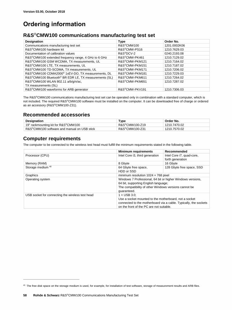
Version 03.00, October 2018
58 Rohde & Schwarz R&S®CMW100 Communications Manufacturing Test Set
Ordering information
R&S®CMW100 communications manufacturing test set Designation Type Order No.
Communications manufacturing test set R&S®CMW100 1201.0002K06
R&S®CMW100 hardware kit R&S®CMW-PS16 1210.7629.03
Documentation of calibration values R&S®DCV-2 0240.2193.08
R&S®CMW100 extended frequency range, 4 GHz to 6 GHz R&S®CMW-PK461 1210.7129.02
R&S®CMW100 GSM WCDMA, TX measurements, UL R&S®CMW-PKM121 1210.7164.02
R&S®CMW100 LTE, TX measurements, UL R&S®CMW-PKM151 1210.7187.02
R&S®CMW100 TD-SCDMA, TX measurements, UL R&S®CMW-PKM171 1210.7206.02
R&S®CMW100 CDMA2000® 1xEV-DO, TX measurements, DL R&S®CMW-PKM181 1210.7229.03
R&S®CMW100 Bluetooth® BR EDR LE, TX measurements (SL) R&S®CMW-PKM611 1210.7264.02
R&S®CMW100 WLAN 802.11 a/b/g/n/ac,
TX measurements (SL)
R&S®CMW-PKM651 1210.7287.02
R&S®CMW100 waveforms for ARB generator R&S®CMW-PKV191 1210.7306.03
The R&S®CMW100 communications manufacturing test set can be operated only in combination with a standard computer, which is
not included. The required R&S®CMW100 software must be installed on the computer. It can be downloaded free of charge or ordered
as an accessory (R&S®CMW100-Z31).
Recommended accessories Designation Type Order No.
19" rackmounting kit for R&S®CMW100 R&S®CMW100-Z19 1210.7470.02
R&S®CMW100 software and manual on USB stick R&S®CMW100-Z31 1210.7570.02
Computer requirements The computer to be connected to the wireless test head must fulfill the minimum requirements stated in the following table.
Minimum requirements Recommended
Processor (CPU) Intel Core i3, third generation Intel Core i7, quad-core,
forth generation
Memory (RAM) 8 Gbyte 16 Gbyte
Storage medium 40 64 Gbyte free space,
HDD or SSD
128 Gbyte free space, SSD
Graphics minimum resolution 1024 × 768 pixel
Operating system Windows 7 Professional, 64 bit or higher Windows versions,
64 bit, supporting English language;
The compatibility of other Windows versions cannot be
guaranteed.
USB socket for connecting the wireless test head 1 × USB 3.0;
Use a socket mounted to the motherboard, not a socket
connected to the motherboard via a cable. Typically, the sockets
on the front of the PC are not suitable.
40 The free disk space on the storage medium is used, for example, for installation of test software, storage of measurement results and ARB files.
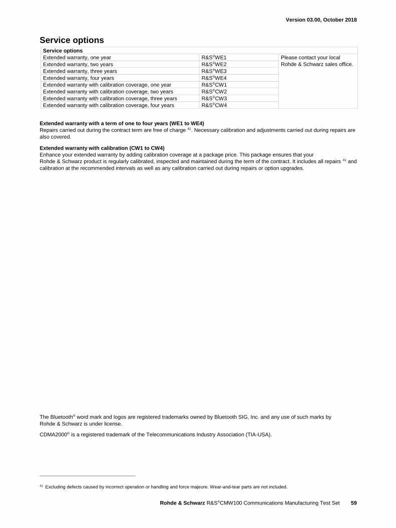
Version 03.00, October 2018
Rohde & Schwarz R&S®CMW100 Communications Manufacturing Test Set 59
Service options Service options
Extended warranty, one year R&S®WE1 Please contact your local
Rohde & Schwarz sales office. Extended warranty, two years R&S®WE2
Extended warranty, three years R&S®WE3
Extended warranty, four years R&S®WE4
Extended warranty with calibration coverage, one year R&S®CW1
Extended warranty with calibration coverage, two years R&S®CW2
Extended warranty with calibration coverage, three years R&S®CW3
Extended warranty with calibration coverage, four years R&S®CW4
Extended warranty with a term of one to four years (WE1 to WE4)
Repairs carried out during the contract term are free of charge 41. Necessary calibration and adjustments carried out during repairs are
also covered.
Extended warranty with calibration (CW1 to CW4)
Enhance your extended warranty by adding calibration coverage at a package price. This package ensures that your
Rohde & Schwarz product is regularly calibrated, inspected and maintained during the term of the contract. It includes all repairs 41 and
calibration at the recommended intervals as well as any calibration carried out during repairs or option upgrades.
The Bluetooth® word mark and logos are registered trademarks owned by Bluetooth SIG, Inc. and any use of such marks by
Rohde & Schwarz is under license.
CDMA2000® is a registered trademark of the Telecommunications Industry Association (TIA-USA).
41 Excluding defects caused by incorrect operation or handling and force majeure. Wear-and-tear parts are not included.
R&S® is a registered trademark of Rohde & Schwarz GmbH & Co. KG
Trade names are trademarks of the owners
PD 5214.8348.22 | Version 03.00 | October 2018 (ch)
R&S®CMW100 Communications Manufacturing Test Set
Data without tolerance limits is not binding | Subject to change
© 2016 - 2018 Rohde & Schwarz GmbH & Co. KG | 81671 Munich, Germany
Service that adds value❙ Worldwide ❙ Local and personalized❙ Customized and flexible❙ Uncompromising quality ❙ Long-term dependability
5214
.834
8.22
03.
00 P
DP
1 e
n
Regional contact ❙ Europe, Africa, Middle East | +49 89 4129 12345 [email protected]
❙ North America | 1 888 TEST RSA (1 888 837 87 72) [email protected]
❙ Latin America | +1 410 910 79 88 [email protected]
❙ Asia Pacific | +65 65 13 04 88 [email protected]
❙ China | +86 800 810 82 28 | +86 400 650 58 96 [email protected]
Rohde & Schwarz trainingwww.training.rohde-schwarz.com
Sustainable product design ❙ Environmental compatibility and eco-footprint ❙ Energy efficiency and low emissions ❙ Longevity and optimized total cost of ownership
Certified Environmental Management
ISO 14001Certified Quality Management
ISO 9001
Rohde & SchwarzThe Rohde & Schwarz electronics group offers innovative solutions in the following business fields: test and mea-surement, broadcast and media, secure communications, cybersecurity, monitoring and network testing. Founded more than 80 years ago, the independent company which is headquartered in Munich, Germany, has an extensive sales and service network with locations in more than 70 countries.
www.rohde-schwarz.com
5214834822
CMW100_K06_dat-sw_en_5214-8348-22_v0300_cover.indd 2 18.10.2018 17:55:12


