128
RSR GNSS Transcoder™ User Manual Document: 80200553 Version: 1.1 Date: 13 September, 2017
RSR GNSSTranscoder™ User
Manual
Document: 80200553Version: 1.1Date: 13 September, 2017
RSR GNSS Transcoder™ User Manual
Copyright © 2017, Jackson Labs Technologies, Inc.
RSR GNSS Transcoder™ User Manual
1 Introduction . . . . . . . . . . . . . . . . . . . . . . . . . . . . . 11.1 Overview . . . . . . . . . . . . . . . . . . . . . . . . . . . . . . . 11.2 Operating Principles . . . . . . . . . . . . . . . . . . . . . . . . . . . 31.3 General Safety Precautions . . . . . . . . . . . . . . . . . . . . . . . . 3
1.3.1 Legacy GPS Receiver Compatibility . . . . . . . . . . . . . . . . . . 41.3.2 Use an approved Antenna Lightning Protector . . . . . . . . . . . . . . 41.3.3 Transmission of synthesized GPS RF signals . . . . . . . . . . . . . . 41.3.4 Grounding . . . . . . . . . . . . . . . . . . . . . . . . . . . . 41.3.5 Power Connections. . . . . . . . . . . . . . . . . . . . . . . . . 41.3.6 Environmental Conditions . . . . . . . . . . . . . . . . . . . . . . 4
2 RSR GNSS Transcoder™ Quick-Start Instructions . . . . . . . 52.1 Introduction . . . . . . . . . . . . . . . . . . . . . . . . . . . . . . 52.2 Power and Control Setup . . . . . . . . . . . . . . . . . . . . . . . . . 52.3 Connecting to Target GPS Receiver’s Antenna Input . . . . . . . . . . . . . . 72.4 Simulation Control . . . . . . . . . . . . . . . . . . . . . . . . . . . 72.5 Simulating to Rockwell Collins DAGR with Battery Power . . . . . . . . . . . . 8
3 Setup and Configuration Instructions . . . . . . . . . . . . . .113.1 Introduction . . . . . . . . . . . . . . . . . . . . . . . . . . . . . .113.2 Operating the Unit . . . . . . . . . . . . . . . . . . . . . . . . . . .12
3.2.1 USB Control and Power . . . . . . . . . . . . . . . . . . . . . . .123.2.2 DC Power supply: 7V to 36V . . . . . . . . . . . . . . . . . . . . .12
3.3 Alternate Powering Supply Options . . . . . . . . . . . . . . . . . . . . .133.3.1 Powering external GNSS receivers . . . . . . . . . . . . . . . . . .133.3.2 Powering the RSR GNSS Transcoder™ from an external LiPo or LiIon single-cell battery13
3.4 Connecting to a Users’ GPS Receiver . . . . . . . . . . . . . . . . . . . .143.5 Mechanical Drawing . . . . . . . . . . . . . . . . . . . . . . . . . . .153.6 Major Features . . . . . . . . . . . . . . . . . . . . . . . . . . . . .16
3.6.1 Power/Communication Connector J4 . . . . . . . . . . . . . . . . . .193.6.2 ISP#/SAASM Zeroize and RESET# Connector J3 . . . . . . . . . . . . .203.6.3 RF SMA Connector J5 . . . . . . . . . . . . . . . . . . . . . . .213.6.4 Optional CSAC Holdover Oscillator . . . . . . . . . . . . . . . . . .21
3.7 Optional IP67 Water-Proof enclosure . . . . . . . . . . . . . . . . . . . .223.7.1 Compatible Water-Proof DB-15 Male Connector . . . . . . . . . . . . .25
3.8 Operating Modes of the RSR GNSS Transcoder™ . . . . . . . . . . . . . . .253.8.1 Transcoding with External GNSS Receiver . . . . . . . . . . . . . . .263.8.2 Detecting and Configuring External GNSS Receiver . . . . . . . . . . . .27
3.8.2.1 Connecting a Rockwell Collins RSR SAASM Puck and/or MicroGRAM SAASM GPS283.8.2.2 Connecting a uBlox GNSS Receiver . . . . . . . . . . . . . . .28
3.8.3 Manually entering Lat/Long/Height Simulation Coordinates . . . . . . . . .283.8.4 Simulating from Internally Stored Motion Commands. . . . . . . . . . . .293.8.5 Configuring the GPS Constellation . . . . . . . . . . . . . . . . . . .30
3.8.5.1 Uploading Almanac and Ephemerides Data . . . . . . . . . . . .303.8.6 Excluding Space Vehicles from Simulation. . . . . . . . . . . . . . . .313.8.7 Satellite Elevation Mask Angle . . . . . . . . . . . . . . . . . . . .313.8.8 Using the Position Filtering and INS Capabilities . . . . . . . . . . . . .313.8.9 Adjusting the RF Output Power Level. . . . . . . . . . . . . . . . . .333.8.10Enabling RF Test-Tone Output . . . . . . . . . . . . . . . . . . . .333.8.11Configuring the simulated Time and Date . . . . . . . . . . . . . . . .34
© 2017 Jackson Labs Technologies, Inc. i
RSR GNSS Transcoder™ User Manual
3.8.12Simulating Leap Second Event . . . . . . . . . . . . . . . . . . . . 343.8.13Simulating 1023 Week Number Rollover . . . . . . . . . . . . . . . . 353.8.14Simulating for GPS Spoofing . . . . . . . . . . . . . . . . . . . . 353.8.15Monitoring the optional CSAC Oscillator . . . . . . . . . . . . . . . . 363.8.16Monitoring the External and Internal GNSS Receivers . . . . . . . . . . . 37
3.8.16.1External Rockwell Microgram and RSR Features . . . . . . . . . 37
4 SCPI Command Reference . . . . . . . . . . . . . . . . . . . . 394.1 Introduction . . . . . . . . . . . . . . . . . . . . . . . . . . . . . . 394.2 General SCPI Commands . . . . . . . . . . . . . . . . . . . . . . . . 40
4.2.1 *IDN?. . . . . . . . . . . . . . . . . . . . . . . . . . . . . . 404.2.2 HELP? . . . . . . . . . . . . . . . . . . . . . . . . . . . . . 40
4.3 Simulation Subsystem. . . . . . . . . . . . . . . . . . . . . . . . . . 404.3.1 SIMulation:MODE . . . . . . . . . . . . . . . . . . . . . . . . . 424.3.2 SIMulation:COMmand . . . . . . . . . . . . . . . . . . . . . . . 424.3.3 SIMulation:STATe? . . . . . . . . . . . . . . . . . . . . . . . . 424.3.4 SIMulation:HOLDover:MODE . . . . . . . . . . . . . . . . . . . . 434.3.5 SIMulation:HOLDover:STATe? . . . . . . . . . . . . . . . . . . . . 434.3.6 SIMulation:HOLDover:LIMIT . . . . . . . . . . . . . . . . . . . . . 434.3.7 SIMulation:HOLDover:INDicate. . . . . . . . . . . . . . . . . . . . 434.3.8 SIMulation:POSition:MODE . . . . . . . . . . . . . . . . . . . . . 444.3.9 SIMulation:POSition:LLH . . . . . . . . . . . . . . . . . . . . . . 444.3.10SIMulation:POSition:ECEF . . . . . . . . . . . . . . . . . . . . . 444.3.11SIMulation:POSition:FILTer:MODE . . . . . . . . . . . . . . . . . . 454.3.12SIMulation:POSition:FILTer:LLH?. . . . . . . . . . . . . . . . . . . 454.3.13SIMulation:POSition:FILTer:ECEF? . . . . . . . . . . . . . . . . . . 454.3.14SIMulation:POSition:FILTer:VMAX . . . . . . . . . . . . . . . . . . 454.3.15SIMulation:POSition:FILTer:AMAX . . . . . . . . . . . . . . . . . . 454.3.16SIMulation:POSition:FILTer:JMAX . . . . . . . . . . . . . . . . . . 464.3.17SIMulation:POSition:FILTer? . . . . . . . . . . . . . . . . . . . . 464.3.18SIMulation:POSition:MOTION:WRITE . . . . . . . . . . . . . . . . . 464.3.19SIMulation:POSition:MOTION:READ . . . . . . . . . . . . . . . . . 464.3.20SIMulation:POSition:MOTION:START . . . . . . . . . . . . . . . . . 474.3.21Simulation Motion Command Language . . . . . . . . . . . . . . . . 47
4.3.21.1Dynamics . . . . . . . . . . . . . . . . . . . . . . . . . 484.3.21.2Reference. . . . . . . . . . . . . . . . . . . . . . . . . 484.3.21.3Straight . . . . . . . . . . . . . . . . . . . . . . . . . . 484.3.21.4Accelerate . . . . . . . . . . . . . . . . . . . . . . . . 494.3.21.5Turn . . . . . . . . . . . . . . . . . . . . . . . . . . . 494.3.21.6Climb . . . . . . . . . . . . . . . . . . . . . . . . . . 494.3.21.7Waypoint . . . . . . . . . . . . . . . . . . . . . . . . . 504.3.21.8Combined Accelerate/Turn . . . . . . . . . . . . . . . . . . 504.3.21.9Combined Accelerate/Turn/Climb . . . . . . . . . . . . . . . 504.3.21.10Halt . . . . . . . . . . . . . . . . . . . . . . . . . . . 514.3.21.11End . . . . . . . . . . . . . . . . . . . . . . . . . . . 51
4.3.22SIMulation:POSition? . . . . . . . . . . . . . . . . . . . . . . . 514.3.23SIMulation:TRACe . . . . . . . . . . . . . . . . . . . . . . . . 524.3.24SIMulation:SV:VIEW? . . . . . . . . . . . . . . . . . . . . . . . 534.3.25SIMulation:SV:EXCLude . . . . . . . . . . . . . . . . . . . . . . 534.3.26SIMulation:SV:MASK . . . . . . . . . . . . . . . . . . . . . . . 534.3.27SIMulation:SV:TRACe . . . . . . . . . . . . . . . . . . . . . . . 53
ii © 2017 Jackson Labs Technologies, Inc.
RSR GNSS Transcoder™ User Manual
4.3.28SIMulation:SV? . . . . . . . . . . . . . . . . . . . . . . . . . .544.3.29SIMulation:TIME:MODE . . . . . . . . . . . . . . . . . . . . . . .544.3.30SIMulation:TIME:START:TIME . . . . . . . . . . . . . . . . . . . .544.3.31SIMulation:TIME:START:DATE . . . . . . . . . . . . . . . . . . . .544.3.32SIMulation:TIME:LEAPsecond:ACCumulated . . . . . . . . . . . . . .554.3.33SIMulation:TIME:LEAPsecond:DATE. . . . . . . . . . . . . . . . . .554.3.34SIMulation:TIME:LEAPsecond:DURation . . . . . . . . . . . . . . . .554.3.35SIMulation:TIME:UTCoffset:A0 . . . . . . . . . . . . . . . . . . . .554.3.36SIMulation:TIME:UTCoffset:A1 . . . . . . . . . . . . . . . . . . . .554.3.37SIMulation:TIME:UTCoffset:DELTATLS. . . . . . . . . . . . . . . . .564.3.38SIMulation:TIME:UTCoffset:TOT . . . . . . . . . . . . . . . . . . .564.3.39SIMulation:TIME:UTCoffset:WNT . . . . . . . . . . . . . . . . . . .564.3.40SIMulation:TIME:UTCoffset:WNLSF . . . . . . . . . . . . . . . . . .564.3.41SIMulation:TIME:UTCoffset:DN . . . . . . . . . . . . . . . . . . . .564.3.42SIMulation:TIME:UTCoffset:DELTATLSF . . . . . . . . . . . . . . . .564.3.43SIMulation:TIME:UTCoffset? . . . . . . . . . . . . . . . . . . . . .574.3.44SIMulation:TIME? . . . . . . . . . . . . . . . . . . . . . . . . .574.3.45SIMulation:IONosphere:A . . . . . . . . . . . . . . . . . . . . . .574.3.46SIMulation:IONosphere:B . . . . . . . . . . . . . . . . . . . . . .574.3.47SIMulation:LNAV:IONosphere . . . . . . . . . . . . . . . . . . . .574.3.48SIMulation:LNAV:EPHemeris . . . . . . . . . . . . . . . . . . . . .584.3.49SIMulation:LNAV:WRITE . . . . . . . . . . . . . . . . . . . . . .594.3.50SIMulation:LNAV:EEPROM? . . . . . . . . . . . . . . . . . . . . .594.3.51SIMulation:LNAV:ACTIVE? . . . . . . . . . . . . . . . . . . . . .594.3.52SIMulation:LNAV:SELect . . . . . . . . . . . . . . . . . . . . . .59
4.4 SIMulation? . . . . . . . . . . . . . . . . . . . . . . . . . . . . . .594.5 Output Subsystem . . . . . . . . . . . . . . . . . . . . . . . . . . .60
4.5.1 OUTput:TEST . . . . . . . . . . . . . . . . . . . . . . . . . . .604.5.2 OUTput:DCBlock <ON|OFF> . . . . . . . . . . . . . . . . . . . . .614.5.3 OUTput:POWer?. . . . . . . . . . . . . . . . . . . . . . . . . .614.5.4 OUTput:OFFset? . . . . . . . . . . . . . . . . . . . . . . . . .614.5.5 OUTput:10Mhz . . . . . . . . . . . . . . . . . . . . . . . . . .624.5.6 OUTput? . . . . . . . . . . . . . . . . . . . . . . . . . . . . .62
4.6 Calibration Subsystem . . . . . . . . . . . . . . . . . . . . . . . . . .624.7 SYNChronization Subsystem . . . . . . . . . . . . . . . . . . . . . . .62
4.7.1 SYNChronization:HOLDover:DURation? . . . . . . . . . . . . . . . .634.7.2 SYNChronization:HOLDover:INITiate. . . . . . . . . . . . . . . . . .634.7.3 SYNChronization:HOLDover:RECovery:INITiate . . . . . . . . . . . . .634.7.4 SYNChronization:SOURce:MODE . . . . . . . . . . . . . . . . . . .634.7.5 SYNChronization:SOURce:STATE? . . . . . . . . . . . . . . . . . .634.7.6 SYNChronization:TINTerval? . . . . . . . . . . . . . . . . . . . . .644.7.7 SYNChronization:TINTerval:THReshold [50,2000]. . . . . . . . . . . . .644.7.8 SYNChronization:IMMEdiate . . . . . . . . . . . . . . . . . . . . .644.7.9 SYNChronization:FEEstimate? . . . . . . . . . . . . . . . . . . . .644.7.10SYNChronization:LOCKed? . . . . . . . . . . . . . . . . . . . . .644.7.11SYNChronization:OUTput:1PPS:RESET [ON|OFF] . . . . . . . . . . . .644.7.12SYNChronization:health? . . . . . . . . . . . . . . . . . . . . . .654.7.13SYNChronization? . . . . . . . . . . . . . . . . . . . . . . . . .66
4.8 DIAGnostic Subsystem. . . . . . . . . . . . . . . . . . . . . . . . . .664.8.1 DIAGnostic:ROSCillator:EFControl:RELative? . . . . . . . . . . . . . .664.8.2 DIAGnostic:ROSCillator:EFControl:ABSolute? . . . . . . . . . . . . . .664.8.3 DIAGnostic:LIFetime:COUNt? . . . . . . . . . . . . . . . . . . . .66
© 2017 Jackson Labs Technologies, Inc. iii
RSR GNSS Transcoder™ User Manual
4.9 MEASURE Subsystem . . . . . . . . . . . . . . . . . . . . . . . . . 664.9.1 MEASure:TEMPerature? . . . . . . . . . . . . . . . . . . . . . . 674.9.2 MEASure:VOLTage?. . . . . . . . . . . . . . . . . . . . . . . . 674.9.3 MEASure:POWer? . . . . . . . . . . . . . . . . . . . . . . . . 674.9.4 MEASure:POWer:V12 . . . . . . . . . . . . . . . . . . . . . . . 674.9.5 MEASure:POWer:V25 . . . . . . . . . . . . . . . . . . . . . . . 674.9.6 MEASure:CURRent?. . . . . . . . . . . . . . . . . . . . . . . . 674.9.7 MEASure? . . . . . . . . . . . . . . . . . . . . . . . . . . . . 67
4.10GPS Subsystem . . . . . . . . . . . . . . . . . . . . . . . . . . . . 684.10.1GPS:TYPE? . . . . . . . . . . . . . . . . . . . . . . . . . . . 694.10.2GPS:TYPE:MODE . . . . . . . . . . . . . . . . . . . . . . . . 694.10.3GPS:SATellite:TRAcking:COUNt? . . . . . . . . . . . . . . . . . . 704.10.4GPS:SATellite:VISible:COUNt? . . . . . . . . . . . . . . . . . . . 704.10.5 NMEA Support . . . . . . . . . . . . . . . . . . . . . . . . . . 704.10.6GPS:GPGGA . . . . . . . . . . . . . . . . . . . . . . . . . . 704.10.7GPS:GPRMC . . . . . . . . . . . . . . . . . . . . . . . . . . 714.10.8GPS:GPZDA . . . . . . . . . . . . . . . . . . . . . . . . . . . 714.10.9GPS:GPGSV. . . . . . . . . . . . . . . . . . . . . . . . . . . 714.10.10GPS:PASHR . . . . . . . . . . . . . . . . . . . . . . . . . . 724.10.11GPS:XYZSPeed . . . . . . . . . . . . . . . . . . . . . . . . . 724.10.12GPS:HEIGHT:MSL? . . . . . . . . . . . . . . . . . . . . . . . 734.10.13GPS:HEIGHT:GPS? . . . . . . . . . . . . . . . . . . . . . . . 734.10.14GPS:HEIGHT? . . . . . . . . . . . . . . . . . . . . . . . . . 734.10.15GPS:DYNAMic:MODE . . . . . . . . . . . . . . . . . . . . . . 734.10.16GPS:DYNAMic:MODE 8 (Automatic Dynamic Mode). . . . . . . . . . . 754.10.17GPS:DYNAMic:STATe? . . . . . . . . . . . . . . . . . . . . . . 764.10.18GPS:REFerence:ADELay <float> <s | ns > [-32767ns,32767ns] . . . . . . 764.10.19GPS:REFerence:PULse:SAWtooth? . . . . . . . . . . . . . . . . . 764.10.20GPS:RESET ONCE . . . . . . . . . . . . . . . . . . . . . . . 764.10.21GPS:TMODe <ON | OFF | RSTSURV> . . . . . . . . . . . . . . . . 774.10.22GPS:SURVey ONCE . . . . . . . . . . . . . . . . . . . . . . . 774.10.23GPS:SURVey:DURation <sec> . . . . . . . . . . . . . . . . . . . 774.10.24GPS:SURVey:VARiance <mm2> . . . . . . . . . . . . . . . . . . 774.10.25GPS:HOLD:POSition <cm, cm, cm> . . . . . . . . . . . . . . . . . 774.10.26GPS:SURVey:STATus? . . . . . . . . . . . . . . . . . . . . . . 784.10.27GPS:INITial:DATE <yyyy,mm,dd> . . . . . . . . . . . . . . . . . . 784.10.28GPS:INITial:TIME <hour,min,sec> . . . . . . . . . . . . . . . . . . 784.10.29GPS:SYST:SELect [GPS | SBAS | QZSS | GAL | BD | GLO] . . . . . . . . 784.10.30GPS:JAMlevel? . . . . . . . . . . . . . . . . . . . . . . . . . 794.10.31GPS:FWver? . . . . . . . . . . . . . . . . . . . . . . . . . . 794.10.32GPS:DAGR:MODE . . . . . . . . . . . . . . . . . . . . . . . . 794.10.33GPS:DAGR:MODE? . . . . . . . . . . . . . . . . . . . . . . . 794.10.34GPS:DAGR:XFERstate?. . . . . . . . . . . . . . . . . . . . . . 804.10.35GPS:DAGR:PVTstate? . . . . . . . . . . . . . . . . . . . . . . 804.10.36GPS:SASTAT:YTRACK? . . . . . . . . . . . . . . . . . . . . . 804.10.37GPS:SASTAT:CVZStatus? . . . . . . . . . . . . . . . . . . . . . 804.10.38GPS:SASTAT:CVKFStatus? . . . . . . . . . . . . . . . . . . . . 814.10.39GPS:SASTAT:CVStatus? . . . . . . . . . . . . . . . . . . . . . 814.10.40GPS:SASTAT:VERification? . . . . . . . . . . . . . . . . . . . . 814.10.41GPS:SASTAT:CVExp? . . . . . . . . . . . . . . . . . . . . . . 814.10.42GPS:SASTAT:KDP? . . . . . . . . . . . . . . . . . . . . . . . 824.10.43GPS:SASTAT:ANTISpoof? . . . . . . . . . . . . . . . . . . . . . 82
iv © 2017 Jackson Labs Technologies, Inc.
RSR GNSS Transcoder™ User Manual
4.10.44GPS:SASTAT <int> [0,255] . . . . . . . . . . . . . . . . . . . . .824.10.45GPS:ZEROize START . . . . . . . . . . . . . . . . . . . . . . .834.10.46GPS:ZEROize? . . . . . . . . . . . . . . . . . . . . . . . . .834.10.47GPS? . . . . . . . . . . . . . . . . . . . . . . . . . . . . .83
4.11INTGPS Subsystem. . . . . . . . . . . . . . . . . . . . . . . . . . .834.11.1INTGPS:SATellite . . . . . . . . . . . . . . . . . . . . . . . . .844.11.2INTGPS:SATellite:TRAcking:COUNt? . . . . . . . . . . . . . . . . .844.11.3INTGPS:SATellite:VISible:COUNt? . . . . . . . . . . . . . . . . . .844.11.4Internal GNSS Receiver NMEA Support . . . . . . . . . . . . . . . .844.11.5INTGPS:GPGGA . . . . . . . . . . . . . . . . . . . . . . . . .854.11.6INTGPS:GPRMC . . . . . . . . . . . . . . . . . . . . . . . . .854.11.7INTGPS:GPGSV . . . . . . . . . . . . . . . . . . . . . . . . .854.11.8INTGPS:XYZSPeed . . . . . . . . . . . . . . . . . . . . . . . .854.11.9INTGPS:GPZDA. . . . . . . . . . . . . . . . . . . . . . . . . .864.11.10INTGPS:PASHR . . . . . . . . . . . . . . . . . . . . . . . . .864.11.11INTGPS:HEIGHT:MSL? . . . . . . . . . . . . . . . . . . . . . .874.11.12INTGPS:HEIGHT:GPS? . . . . . . . . . . . . . . . . . . . . . .874.11.13INTGPS:HEIGHT? . . . . . . . . . . . . . . . . . . . . . . . .874.11.14INTGPS:DYNAMic:MODE . . . . . . . . . . . . . . . . . . . . .874.11.15INTGPS:DYNAMic:MODE 8 (Automatic Dynamic Mode) . . . . . . . . .884.11.16INTGPS:DYNAMic:STATe? . . . . . . . . . . . . . . . . . . . . .894.11.17INTGPS:REFerence:PULse:SAWtooth? . . . . . . . . . . . . . . . .894.11.18INTGPS:RESET ONCE . . . . . . . . . . . . . . . . . . . . . .894.11.19INTGPS:JAMlevel? . . . . . . . . . . . . . . . . . . . . . . . .904.11.20INTGPS:FWver? . . . . . . . . . . . . . . . . . . . . . . . . .904.11.21INTGPS? . . . . . . . . . . . . . . . . . . . . . . . . . . . .90
4.12PTIME Subsystem . . . . . . . . . . . . . . . . . . . . . . . . . . .904.12.1PTIMe:DATE? . . . . . . . . . . . . . . . . . . . . . . . . . .904.12.2PTIMe:TIME? . . . . . . . . . . . . . . . . . . . . . . . . . . .914.12.3PTIMe:TIME:STRing? . . . . . . . . . . . . . . . . . . . . . . .914.12.4PTIME:OUTput <ON | OFF> . . . . . . . . . . . . . . . . . . . . .914.12.5PTIMe:LEAPsecond? . . . . . . . . . . . . . . . . . . . . . . . .914.12.6PTIMe:LEAPsecond:PENDing? . . . . . . . . . . . . . . . . . . . .914.12.7PTIMe:LEAPsecond:ACCumulated? . . . . . . . . . . . . . . . . . .914.12.8PTIMe:LEAPsecond:DATE? . . . . . . . . . . . . . . . . . . . . .914.12.9PTIMe:LEAPsecond:DURation?. . . . . . . . . . . . . . . . . . . .924.12.10PTIME?. . . . . . . . . . . . . . . . . . . . . . . . . . . . .92
4.13SYSTEM Subsystem . . . . . . . . . . . . . . . . . . . . . . . . . .924.13.1SYSTem:COMMunicate:SERial:ECHO . . . . . . . . . . . . . . . . .924.13.2SYSTem:COMMunicate:SERial:PROmpt . . . . . . . . . . . . . . . .924.13.3SYSTem:COMMunicate:SERial:BAUD . . . . . . . . . . . . . . . . .934.13.4SYSTem:FACToryreset ONCE . . . . . . . . . . . . . . . . . . . .934.13.5SYSTem:ID:SN?. . . . . . . . . . . . . . . . . . . . . . . . . .934.13.6SYSTem:ID:HWrev? . . . . . . . . . . . . . . . . . . . . . . . .934.13.7SYSTem:STATus? . . . . . . . . . . . . . . . . . . . . . . . . .93
4.14SERVO Subsystem . . . . . . . . . . . . . . . . . . . . . . . . . . .934.14.1SERVo:LOOP? . . . . . . . . . . . . . . . . . . . . . . . . . .944.14.2SERVo:COARSeDac . . . . . . . . . . . . . . . . . . . . . . . .944.14.3SERVo:DACGain . . . . . . . . . . . . . . . . . . . . . . . . .944.14.4SERVo:EFCScale . . . . . . . . . . . . . . . . . . . . . . . . .944.14.5SERVo:EFCDamping . . . . . . . . . . . . . . . . . . . . . . . .944.14.6SERVo:SLOPe . . . . . . . . . . . . . . . . . . . . . . . . . .94
© 2017 Jackson Labs Technologies, Inc. v
RSR GNSS Transcoder™ User Manual
4.14.7SERVo:TEMPCOmpensation . . . . . . . . . . . . . . . . . . . . 944.14.8SERVo:AGINGcompensation . . . . . . . . . . . . . . . . . . . . 954.14.9SERVo:PHASECOrrection . . . . . . . . . . . . . . . . . . . . . 954.14.10SERVo:1PPSoffset . . . . . . . . . . . . . . . . . . . . . . . . 954.14.11SERVo:TRACe . . . . . . . . . . . . . . . . . . . . . . . . . 954.14.12SERVo? . . . . . . . . . . . . . . . . . . . . . . . . . . . . 96
4.15CSAC Subsystem . . . . . . . . . . . . . . . . . . . . . . . . . . . 964.15.1CSAC:POWer . . . . . . . . . . . . . . . . . . . . . . . . . . 964.15.2CSAC:RS232? . . . . . . . . . . . . . . . . . . . . . . . . . . 964.15.3CSAC:STeer? . . . . . . . . . . . . . . . . . . . . . . . . . . 974.15.4CSAC:STATus? . . . . . . . . . . . . . . . . . . . . . . . . . 974.15.5CSAC:ALarm? . . . . . . . . . . . . . . . . . . . . . . . . . . 974.15.6CSAC:MODE? . . . . . . . . . . . . . . . . . . . . . . . . . . 984.15.7CSAC:CONTrast? . . . . . . . . . . . . . . . . . . . . . . . . . 984.15.8CSAC:LASer? . . . . . . . . . . . . . . . . . . . . . . . . . . 984.15.9CSAC:TCXO? . . . . . . . . . . . . . . . . . . . . . . . . . . 984.15.10CSAC:SIGnal? . . . . . . . . . . . . . . . . . . . . . . . . . 984.15.11CSAC:HEATpackage? . . . . . . . . . . . . . . . . . . . . . . 984.15.12CSAC:TEMP? . . . . . . . . . . . . . . . . . . . . . . . . . . 984.15.13CSAC:FWrev?. . . . . . . . . . . . . . . . . . . . . . . . . . 984.15.14CSAC:SN? . . . . . . . . . . . . . . . . . . . . . . . . . . . 994.15.15CSAC:LIFEtime?. . . . . . . . . . . . . . . . . . . . . . . . . 994.15.16CSAC:STeer:LATch ONCE. . . . . . . . . . . . . . . . . . . . . 994.15.17CSAC? . . . . . . . . . . . . . . . . . . . . . . . . . . . . 99
5 Firmware Upgrade Instructions . . . . . . . . . . . . . . . . 1015.1 Introduction . . . . . . . . . . . . . . . . . . . . . . . . . . . . . 1015.2 ISP Flash Loader Utility Installation . . . . . . . . . . . . . . . . . . . 1015.3 Putting the PCB into In-Circuit Programming (ISP) mode . . . . . . . . . . . 1015.4 Downloading the Firmware . . . . . . . . . . . . . . . . . . . . . . . 102
5.4.1 Using the Flash Magic Flash Programming Utility. . . . . . . . . . . . 1035.5 Verifying Firmware Update . . . . . . . . . . . . . . . . . . . . . . . 106
6 GPSCon Utility . . . . . . . . . . . . . . . . . . . . . . . . . . 1076.1 Description . . . . . . . . . . . . . . . . . . . . . . . . . . . . . 1076.2 Installation . . . . . . . . . . . . . . . . . . . . . . . . . . . . . 1076.3 Using GPSCon . . . . . . . . . . . . . . . . . . . . . . . . . . . 107
6.3.1 Setting the options. . . . . . . . . . . . . . . . . . . . . . . . 1076.3.1.1 Communication Parameters. . . . . . . . . . . . . . . . . 1086.3.1.2 Auxiliary Parameters . . . . . . . . . . . . . . . . . . . 1086.3.1.3 Traces Parameters . . . . . . . . . . . . . . . . . . . . 109
6.3.2 Sending manual commands to the receiver . . . . . . . . . . . . . . 1116.3.3 Using the Mouse in the Graph Window. . . . . . . . . . . . . . . . 1116.3.4 Exporting the graphics . . . . . . . . . . . . . . . . . . . . . . 113
6.4 Interpreting the Data . . . . . . . . . . . . . . . . . . . . . . . . . 114
7 Certification and Warranty . . . . . . . . . . . . . . . . . . . 1177.1 Certification . . . . . . . . . . . . . . . . . . . . . . . . . . . . . 117
7.1.1 Warranty . . . . . . . . . . . . . . . . . . . . . . . . . . . 1177.1.2 Limitation of Warranty . . . . . . . . . . . . . . . . . . . . . . 117
vi © 2017 Jackson Labs Technologies, Inc.
RSR GNSS Transcoder™ User Manual
7.1.3 Exclusive Remedies . . . . . . . . . . . . . . . . . . . . . . . 118
© 2017 Jackson Labs Technologies, Inc. vii

RSR GNSS Transcoder™ User Manual
viii © 2017 Jackson Labs Technologies, Inc.
RSR GNSS Transcoder™ User Manual
Introduction
1.1 OverviewThe Jackson Labs RSR GNSS Transcoder™ is a miniature, fully self-contained, real-time, full-constellation, 10-channel GPS simulator. It can be used as an independent GPS L1 RF source just like any other industry-standard GPS simulator, or be connected to an external Position/Velocity/Navigation/Time (PVT/PNT) source to transcode the baseband NMEA PVT/PNT information into an equivalent GPS RF signal in real-time, and without requiring the use of any external equipment such as a PC etc.The JLT RSR GNSS Transcoder™ defines a unique new product category in the market allowing embedded retrofit of any GPS receiver to modern GNSS signals by converting standard GNSS or positioning signals into a legacy L1 GPS RF signal. The transcoding process is performed in real-time using embedded next-generation JLT-designed GPS simulator technology. The device has a miniature form-factor (1.6 x 2.3 x 0.5 inches for the non-CSAC version) with mininal power consumption (<1.1W w/o CSAC typically) and does not require any external equipment other than a power source to operate. The self-contained real-time hardware simulation feature sets it apart from competitive GPS/GNSS simulators that either require an external computer for signal processing and control, or are based on passive record-and-playback technology that is highly inflexible.The RSR GNSS Transcoder™ is a full-constellation, fully-integrated, low SWaP-C Real-Time 10-channel GPS Simulator allowing transcoding of any Position, Velocity, Timing (PVT), or Position, Navigation, Timing (PNT) data into a legacy GPS L1 C/A code RF signal with up to ten satellites being simulated in real-time. The Transcoder optionally has an integrated Cesium Chip Scale Atomic Clock (CSAC) for atomic holdover performance, and is the first fully-integrated real-time miniature embedded GPS full-constellation simulator on the market. The RSR GNSS Transcoder™ allows easy retrofit of legacy GPS receivers with the latest generation GNSS signals such as SAASM, M-Code, Glonass, Galileo, BeiDou, QZSS, or any other emerging GNSS signal, as well as adding Inertial Navigation System (INS) and CSAC holdover capability to existing legacy GPS equipment.Application examples of the RSR GNSS Transcoder™ range from upgrading multiple GPS receivers such as the various DAGR receivers inside a military vehicle to receive the RF signal from a single RSR GNSS Transcoder™ and thus only requiring one RSR GNSS Transcoder to provide assured PVT from only one SAASM-keyed receiver rather than all the DAGR receivers in a vehicle having to be keyed etc, to retrofitting legacy GPS receivers for Galileo, Glonass, BeiDou, SBAS, M-code, or SAASM capability, all by simply replacing the existing GPS antenna with the RSR GNSS Transcoder™ and connecting a suitable GNSS receiver as a front-end to the RSR GNSS
© 2017 Jackson Labs Technologies, Inc. 1
RSR GNSS Transcoder™ User Manual
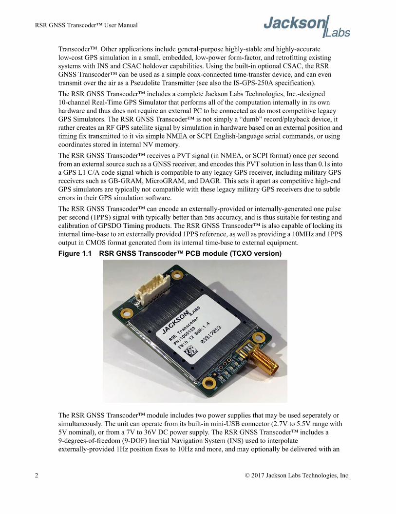
Transcoder™. Other applications include general-purpose highly-stable and highly-accurate low-cost GPS simulation in a small, embedded, low-power form-factor, and retrofitting existing systems with INS and CSAC holdover capabilities. Using the built-in optional CSAC, the RSR GNSS Transcoder™ can be used as a simple coax-connected time-transfer device, and can even transmit over the air as a Pseudolite Transmitter (see also the IS-GPS-250A specification).The RSR GNSS Transcoder™ includes a complete Jackson Labs Technologies, Inc.-designed 10-channel Real-Time GPS Simulator that performs all of the computation internally in its own hardware and thus does not require an external PC to be connected as do most competitive legacy GPS Simulators. The RSR GNSS Transcoder™ is not simply a “dumb” record/playback device, it rather creates an RF GPS satellite signal by simulation in hardware based on an external position and timing fix transmitted to it via simple NMEA or SCPI English-language serial commands, or using coordinates stored in internal NV memory.The RSR GNSS Transcoder™ receives a PVT signal (in NMEA, or SCPI format) once per second from an external source such as a GNSS receiver, and encodes this PVT solution in less than 0.1s into a GPS L1 C/A code signal which is compatible to any legacy GPS receiver, including military GPS receivers such as GB-GRAM, MicroGRAM, and DAGR. This sets it apart as competitive high-end GPS simulators are typically not compatible with these legacy military GPS receivers due to subtle errors in their GPS simulation software.The RSR GNSS Transcoder™ can encode an externally-provided or internally-generated one pulse per second (1PPS) signal with typically better than 5ns accuracy, and is thus suitable for testing and calibration of GPSDO Timing products. The RSR GNSS Transcoder™ is also capable of locking its internal time-base to an externally provided 1PPS reference, as well as providing a 10MHz and 1PPS output in CMOS format generated from its internal time-base to external equipment.Figure 1.1 RSR GNSS Transcoder™ PCB module (TCXO version)
The RSR GNSS Transcoder™ module includes two power supplies that may be used seperately or simultaneously. The unit can operate from its built-in mini-USB connector (2.7V to 5.5V range with 5V nominal), or from a 7V to 36V DC power supply. The RSR GNSS Transcoder™ includes a 9-degrees-of-freedom (9-DOF) Inertial Navigation System (INS) used to interpolate externally-provided 1Hz position fixes to 10Hz and more, and may optionally be delivered with an
2 © 2017 Jackson Labs Technologies, Inc.
RSR GNSS Transcoder™ User Manual
integrated Chip Scale Atomic Clock (CSAC) for ultimate frequency and phase stability and holdover performance.The RSR GNSS Transcoder™ can accept PVT fixes over the RS-232 or USB serial ports via its built-in NMEA parsing as well as using standard SCPI commands. Simulation motion control commands can be stored in internal EEPROM and these commands can be used to automatically start a dynamic simulation scenario with full autonomy from any external control requirements. Front-end GNSS receivers can be connected via the RS-232 serial port with auto-detection and auto-configuration of uBlox and Rockwell Collins GPS receivers such as the MicroGRAM, RSR Puck, GB-GRAM, with uBlox gen. 5, 6, 7, and 8 GNSS receiver product lines also being supported.The RSR GNSS Transcoder™ includes a complete Jackson Labs Technologies, Inc. CSAC GPSDO module which allows automatic disciplining of either the internal high-stability TCXO, or the optional internal CSAC oscillator to an external 1PPS reference using battle-proven JLT disciplining algorithms. The RSR GNSS Transcoder™ also has outputs for CMOS 10MHz and 1PPS signals as generated by the internal CSAC and/or TCXO. The RSR GNSS Transcoder™ is compatible to the GPSCon control and monitoring program available for free on the Jackson Labs Technologies, Inc. website.
1.2 Operating PrinciplesThe RSR GNSS Transcoder™ is based on a next generation, fully integrated, full-constellation GPS simulator. The unit includes an ARM Cortex main processor that handles communications, calculations, and oscillator disciplining, and a high-integration FPGA that includes hardware RF signal generators for each GPS channel. Tight coupling between the processor, the FPGA, and the timing reference allows real-time encoding of PVT/PNT data into a GPS L1 C/A code RF signal. Baseband IF signals in IQ format from each GPS channel go through an adder tree, and are then RF modulated using a TX DAC to the GPS L1 frequency of 1575.42MHz. This is done by using Nyquist harmonics of the DAC sample frequency to avoid having to generate an RF carrier signal or high-power RF artifacts at L1 frequency which are extremely hard to mitigate and to shield due to the extremely low power levels of GPS L1 signals (below -120dBm typically). The RF Nyquist harmonic is then wave-shaped, filtered, and further attenuated. A splitter feeds an on-board 8th generation GNSS receiver which provides signal monitoring and calibration capabilities. The signal is final-filtered, and passed out of a resistive pad that includes a 186 Ohms DC resistance to ground to simulate a typical GPS antenna load to the GNSS DUT receiver. The RSR GNSS Transcoder™ RF output is compatible with external GPS-provided antenna voltages up to 6V.The RSR GNSS Transcoder™ includes circuitry to time-stamp an external 1PPS reference signal to better than +/-2.8ns typically as well as disciplining circuitry for its internal high-stability TCXO or an optional CSAC oscillator mounted onto the board. It also includes a regulated 5.4V power supply circuit to provide power to an external GNSS receiver. Additional features include a USB port, a 9-DOF INS, and a user-controllable RF output power level.
1.3 General Safety PrecautionsThe following general safety precautions must be observed during all phases of operation of this instrument. Failure to comply with these precautions or with specific warnings elsewhere in this manual violates safety standards of design manufacture, and intended use of the instrument. Jackson
© 2017 Jackson Labs Technologies, Inc. 3
RSR GNSS Transcoder™ User Manual
Labs Technologies, Inc. assumes no liability for the customer’s failure to comply with these requirements.
1.3.1 Legacy GPS Receiver CompatibilityJLT strives to achieve as much compatibility as possible to legacy GPS receivers, however if any incompatibilities are encountered please reports these to [email protected].
1.3.2 Use an approved Antenna Lightning ProtectorThe use of an approved, and properly grounded antenna lightning protector on the optional GNSS antenna connected to the external GNSS receiver is required to prevent damage, injury or death in case of a lightning strike.
1.3.3 Transmission of synthesized GPS RF signalsIt is illegal to transmit simulated/synthesized GPS RF signals. The RF output of the RSR GNSS Transcoder™ must not be fed to a transmitting antenna, it is only intended to be directly coupled into an RF input of a GPS receiver using shielded coax cables. The RF output must not be amplified, or re-transmitted in any way without approval from the appropriate government authorities.
1.3.4 GroundingTo avoid damaging the sensitive electronic components in the RSR GNSS Transcoder™ always make sure to discharge any built-up electrostatic charge to a good ground source, such as power supply ground. This should be done before handling the circuit board or anything connected to it, i.e. the GNSS antenna.
1.3.5 Power ConnectionsMake sure to connect the DC power to the device following the polarity indicated in Table 3.2.
1.3.6 Environmental ConditionsThis instrument is intended for indoor use. The use of a properly installed GNSS Antenna Lightning Protector is required. It is designed to operate at a maximum relative non-condensing humidity of 95% and at altitudes of up to 50,000 meters. Refer to the specifications tables for the DC voltage requirements and ambient operating temperature range.
4 © 2017 Jackson Labs Technologies, Inc.
RSR GNSS Transcoder™ User Manual
RSR GNSS Transcoder™ Quick-Start Instructions
2.1 IntroductionThe RSR GNSS Transcoder™ has various hardware connections and configuration options. This chapter focuses on a basic hardware setup and simulation configuration options to start using the RSR GNSS Transcoder as a simulator in minutes. Chapter 3 provides a more detailed description of the available setup and configuration options, and Chapter 4 provides a command reference for the supported SCPI command set.Using the RSR GNSS Transcoder™ as a simulator requires a USB connection to a computer for power and communications and an RF connection to the target GPS receiver. Configuration and status commands are sent through the COM port installed on your computer with the USB connection to the RSR GNSS Transcoder™.
2.2 Power and Control SetupThe power and control connection to the RSR GNSS Transcoder™ is made with a USB cable between the USB mini-B port on the RSR GNSS Transcoder™ and a computer. The location of the USB mini-B port is labeled in Figure 2.1. Power is provided through the 5V USB power. See Section 3.2.1 for more details on the USB connection power requirements.When the cable is connected for the first time, Windows will try to locate and install the drivers. For Windows 8.1 and previous versions, The SiLabs CP2104 drivers must be downloaded from the Silicon Labs website (www.silabs.com). A revised SiLabs Linux driver that fully supports GPSD and NTP is available on the JLT website as well and will need to be used if the 1PPS output feature of the internal TCXO or CSAC is to be used for optional GPSD/NTP functionality. Windows 10 with an
© 2017 Jackson Labs Technologies, Inc. 5
RSR GNSS Transcoder™ User Manual
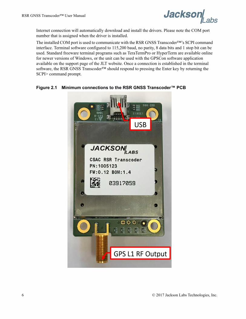
Internet connection will automatically download and install the drivers. Please note the COM port number that is assigned when the driver is installed.The installed COM port is used to communicate with the RSR GNSS Transcoder™’s SCPI command interface. Terminal software configured to 115,200 baud, no parity, 8 data bits and 1 stop bit can be used. Standard freeware terminal programs such as TeraTermPro or HyperTerm are available online for newer versions of Windows, or the unit can be used with the GPSCon software application available on the support page of the JLT website. Once a connection is established in the terminal software, the RSR GNSS Transcoder™ should respond to pressing the Enter key by returning the SCPI> command prompt.
Figure 2.1 Minimum connections to the RSR GNSS Transcoder™ PCB
6 © 2017 Jackson Labs Technologies, Inc.
RSR GNSS Transcoder™ User Manual
2.3 Connecting to Target GPS Receiver’s Antenna InputThe RF output from the RSR GNSS Transcoder connects directly to the antenna input on the target GPS receiver. The SMA GPS L1 RF connector is labeled in Figure 2.1. In addition to an RF output, this connection also provides a 180 Ohm DC load for the antenna output voltage from the target GPS receiver as some GPS receivers provide 3.3V or 5V to the antenna and require an antenna current to operate properly. PLEASE NOTE: If the target receiver’s antenna output voltage is higher than 6V, then a DC block is required between the RSR GNSS Transcoder™’s RF output and the target receiver’s antenna input. An example of this is the Symmetricom/Microsemi XLI reference, it outputs 12V DC which would damage the 180 Ohms DC termination resistor. Use an appropriate RF cable to connect the SMA RF output to the antenna input of the target receiver, and add a DC block as necessary.
2.4 Simulation ControlThis section describes basic command examples for setting up a fixed position simulation with specified location and start time, adding manual start/stop control. These commands are entered at the SCPI command prompt in the terminal program described in Section 2.2 . Each command is terminated with a carriage return character (Enter key).For manual START/STOP simulation control, set the simulation mode to manual:
SIM:MODE MANUALTo set the fixed position of the simulation enter the command:
SIM:POS:LLH lat,lon,heightwhere lat and lon are latitude and longitude in degrees and height is in meters above the GPS ellipsoid (not Mean Sea Level height). A user may enter one or more of the lat/long/height parameters, so for example to just change the simulated height enter:
SIM:POS:LLH ,,heightThe simulated time can be manually set. This means the GPS receiver will indicate the start time and date as soon as the simulation commences. This allows simulating any time/date in the future or past as required.To set the assigned start time, set the time mode to Assigned mode:
SIM:TIME:MODE ASSIGNEDNext, set the assigned start time and date with the commands:
SIM:TIME:START:TIME hh,mm,ss.sssand
SIM:TIME:START:DATE yyyy,mm,ddFinally, start the simulation with the command:
SIM:COMMAND STARTThe simulation will start immediatly after the Enter key has been received, and the GPS receiver should indicate the selected time/date.The simulation will run indefiniately or until stopped with the command:
SIM:COMMAND STOP
© 2017 Jackson Labs Technologies, Inc. 7
RSR GNSS Transcoder™ User Manual
The RF output power of the simulated GPS signal can be controlled with the command OUT:POW -xxx
Where xxx is the desired power level in dBm. The “dBm” abbreviation does not have to be entered, it is assumed. Available power levels range from about -100 to -125 dBm.
2.5 Simulating to Rockwell Collins DAGR with Battery PowerWith the RSR GNSS Transcoder™ still connected for SCPI port control as described above, set the Simulation mode to Simulation with the following command:
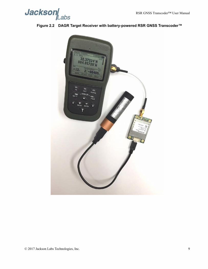
SIM:MODE SIMIn Simulation mode, The RSR GNSS Transcoder™ will start simulating on power up using the previously assigned start time, start date and fixed position as described in Section 2.4 . Because a computer is not required to start the simulation, the Simulation mode is useful for battery operated testing or demonstrations like the one described in this section.Figure 2.2 shows the setup for simulating GPS L1 signals to a Rockwell Collins DAGR. The RSR GNSS Transcoder™ is powered by the USB port with a 5V USB power bank. When the power bank is connected, the simulation will start as indicated by the PWR/XT LED blinking at 5Hz. The RF output from the RSR GNSS Transcoder™ is connected to the external antenna input on the DAGR. The DAGR uses the 180 Ohm DC termination resistor in the RSR GNSS Transcoder™ to detect the presence of an external antenna or simulator in this case.The DAGR will start to track satellites and obtain a position fix. Figure 2.2 shows the DAGR with a position fix from the RSR GNSS Transcoder™’s RF output. If no fix is obtained after one or two minutes, then check that the DAGR detects the RSR GNSS Transcoder™ as an external antenna by disconnecting the RF cable. The DAGR should display an error message that the external antenna connection is lost if the RSR GNSS Transcoder was detected correctly.Also, because the DAGR maintains a real time clock with the battery backup, it may be necessary to remove the battery backup for the DAGR to continuously track the simulated signals from the RSR GNSS Transcoder™. Removing the battery backup is only necessary because the simulated time does not match the correct time. So removing the battery backup is not necessary for Transcoding applications.
8 © 2017 Jackson Labs Technologies, Inc.
RSR GNSS Transcoder™ User Manual
Figure 2.2 DAGR Target Receiver with battery-powered RSR GNSS Transcoder™
© 2017 Jackson Labs Technologies, Inc. 9

RSR GNSS Transcoder™ User Manual
10 © 2017 Jackson Labs Technologies, Inc.
RSR GNSS Transcoder™ User Manual
Setup and Configuration Instructions
3.1 IntroductionThe RSR GNSS Transcoder™ is a miniature real-time full-constellation GPS simulator. It is designed to receive inputs from an external PVT/PNT source such as a GNSS receiver via an RS-232 serial port, and to connect to a legacy GPS receiver via the GPS L1 RF output, allowing transcoding of any GNSS system into GPS. The RSR GNSS Transcoder™ includes special embedded design features such as a PCB outline that allows direct mating to a Rockwell Collins RSR Puck SAASM receiver. The unit can also be used with many other industry-standard GNSS receivers, or as a stand-alone general-purpose GPS simulator under user-control. The RSR GNSS Transcoder™ at its heart is a full-constellation, real-time, 10-channel GPS simulator, and may also be used as a simple small SWaP-C high-quality GPS simulator for R&D, manufacuring, or in-field testing rather than in a dedicated GNSS-transcoding type of application.The RF output of the RSR GNSS Transcoder™ simulates the GPS signals that would normally be present in a Live-Sky GPS antenna feed. The RSR GNSS Transcoder™ includes a USB port that can provide power to the unit (alternatively a DC power source of 7V to 36V with 12V nominal can also be used). The USB port is used as a control/monitoring serial port using the GPSCon application software (available on the support page under www.jackson-labs.com) or using standard terminal programs such as TeraTermPro. A dedicated JLT Windows application program will be made available at no cost in late 2017.Once powered, the RSR GNSS Transcoder™ will generate a GPS L1 C/A RF output signal that is compatible with legacy GPS receivers. The unit will either output a fixed position stored in memory, or it will output a position equal to the NMEA input position on the RS-232 serial input port. This transcoding from NMEA RS-232 base-band PVT signals into GPS RF signals allows the use of any external GNSS receiver source such as SAASM, M-Code, Glonass, Galileo, or BeiDou receivers, or even positioning sources such as INS modules etc, and for these sources to be transcoded in real-time into legacy GPS RF signals. The RF output of the RSR GNSS Transcoder™ is attenuated to about -120dBm per satellite which results in typical Carrier to Noise (C/No) values of 42dB to 47dB on
© 2017 Jackson Labs Technologies, Inc. 11
RSR GNSS Transcoder™ User Manual
typical 8th-generation target GPS receivers. This low RF power level avoids accidental re-broadcasting of signals through faulty (leaky) antenna coax cables, and it closely imitates the signal levels that a typical industry-standard active GPS antenna with a good view of the sky would present to a GPS receiver. The RF output power level is adjustable through standard SCPI user commands for further fine-tuning ability.To enhance the capabilities of the unit, a 9-degrees-of-freedom (9-DOF) MEMS IMU is integrated into the board that is used to create intermediate position- and velocity-fixes up to 10Hz and more, and an optional CSAC is used to provide exceptional timing accuracy even during extended holdover (flywheel) events during which the external GNSS receiver or 1PPS reference is not able to provide a PVT fix. The RSR GNSS Transcoder™ also includes an internal GPS receiver that continuously monitors the RF output signal on the SMA connector for signal strength and PVT/PNT fix quality.
3.2 Operating the UnitThe RSR GNSS Transcoder™ is physically designed to fit, and be mounted below a Rockwell RSR SAASM Puck. An optional IP67-rated water-proof enclosure is available for vehicle mounted or desktop applications. It can also be used as a stand-alone unit without external GNSS receiver. Stand-alone use with the optional CSAC installed on the unit allows time-transfer to any GPS receiver with nanoseconds accuracy and CSAC Atomic Clock holdover performance. Power can be applied through the USB port, or through the Avionics-compatible 7V to 36V DC power port. Please note that the unit will typically generate an RF output shortly after power is applied. The RF output connector of the unit does not need to be terminated if unused, however it is recommended to terminate the output to avoid leakage of GPS RF signals out of the coax connector.The unit is available in a special-order variant from Rockwell Collins with a molded enclosure that conforms to the Rockwell RSR Puck outline, or as a standard PCB module.
3.2.1 USB Control and PowerThe integrated mini-USB connector can be used to power the RSR GNSS Transcoder™ from external industry-standard USB battery sticks, USB Wall-Wart supplies, or from a PC. The allowable voltage range for USB power is 2.7V to 5.6V with 5V nominal. Power consumption is low at less than 1.2W, allowing extended operating times with small batteries. The unit will also show up as a standard USB serial port when plugged into a PC (the integrated Si2104 USB interface chip drivers can be downloaded from the Silicon Labs and/or JLT website), and can be controlled by GPSCon or a terminal program at 115,200 Baud, 8N1, with no flow-control. The GPSCon Windows application can be downloaded from www.jackson-labs.com. Typical power consumption through the USB port is about 1.18W at 5V without the CSAC option, and about 1.35W with the CSAC option.
3.2.2 DC Power supply: 7V to 36VAn alternative way to power the unit other than through the USB port is to use the DC power input port. The RSR GNSS Transcoder™ includes a vehicle and avionics-compatible DC-DC switching power supply with noise filtering. DC Prime power is applied to pin 2 of connector J4, and ground applied to pin 4 of J4. The allowable voltage range on this DC power port is 7V to 36V, with a nominal voltage of 12V. The unit can be alternatively powered by the USB port, or from the DC port, or from both at the same time. The USB port is diode-protected from back-feeding power from the internal DC-DC switcher when operating from the 7V to 36V supply. Typical power consumption of
12 © 2017 Jackson Labs Technologies, Inc.
RSR GNSS Transcoder™ User Manual
the RSR GNSS Transcoder™ is about 0.12A at 12V without the CSAC option, and about 0.14A with the CSAC option installed.
3.3 Alternate Powering Supply OptionsThe RSR GNSS Transcoder™ module has the capability to provide power to the external GNSS receiver via pin 11 of connector J4. This pin has multiple usage capabilities as listed below:
3.3.1 Powering external GNSS receiversThe RSR GNSS Transcoder™ includes connector J4 with signals designed to interface glue-lessly to an external GNSS receiver such as the Rockwell RSR SAASM Puck. It provides power to the external GNSS receiver, as well as RS-232 level serial communications and TTL/CMOS level 1PPS interfacing from the external GNSS receiver. External GNSS receivers are assumed to be compatible to a prime-power input of between 2.7V and 5.5V, with 5V nominal.When connecting pin 11 of J4 to the prime-power input of the Rockwell RSR Puck or other external GNSS receivers, the unit will provide either the supplied USB voltage (2.7V to 5.5V range) to the Puck, or it will provide an internally regulated 5.4V supply (whichever is the higher of the two) generated from the external 7V to 36V DC prime-power port. The Rockwell Puck or other external GNSS receiver can thus be fully powered by connector J4 of the RSR GNSS Transcoder™ module and does not require any other wiring connections than those to the transcoder module.
3.3.2 Powering the RSR GNSS Transcoder™ from an external LiPo or LiIon single-cell batteryWhile the primary use of pin 11 of connector J4 is to provide a regulated power to an external GNSS receiver, pin 11 of J4 can alternatively be used as a power input to the RSR GNSS Transcoder™ as well as the Rockwell RSR Puck or other external GNSS receiver from a single-cell LiPo or LiIon battery. Pin 11 will then act as a power-input to the RSR GNSS Transcoder™, and voltages between 2.7V to 5.5V can be applied, with a typical LiPo battery providing a range of 4.2V (charged) to 3.7V (dis-charged). The 4.2V battery power is typically split up and fed to the prime-power input of the Rockwell RSR Puck, as well as into pin 11 of connector J4 of the RSR GNSS Transcoder™. USB power and power to pin 2 of J11 must not be connected when using pin 11 of J4 as the prime power input to the RSR GNSS Transcoder™.Please note that the RSR GNSS Transcoder™ nor the Rockwell RSR Puck DO NOT disable the current draw (do not disconnect the battery) when the LiPo minimum allowable battery voltage of 3.7V is reached, and continuing to operate the RSR GNSS Transcoder™ from the LiPo or LiIon battery below 3.7V cell voltage may damage the battery or cause a battery fire. The user must disconnect the battery externally before the terminal cell voltage of 3.7V is reached. External charge and control IC’s are readily available that prevent under-voltage conditions on LiPo/LiIon batteries, and these should be used when using the system with direct battery power on any of the power input connections.Please note that if power is applied to the USB port or the DC 7V to 36V port that the external LiPo/LiIon battery will be charged with up to 5.5V. This can result in battery failure and a battery fire, and thus simultaneous operation of a battery connected to J4 pin 11 and any other external power source is not allowed.
© 2017 Jackson Labs Technologies, Inc. 13
RSR GNSS Transcoder™ User Manual
Powering the RSR GNSS Transcoder™ from a 5V supply on pin 11 of connector J4 results in the least overall power consumption as the USB port has losses associated with the USB power protection series diode, and the DC 7V to 36V has losses associated with the internal 36V to 5.4V switching regulator. Pin 11 of J4 should receive a regulated and clean 5V power input for applications that require the lowest possible overall power consumption, while the USB power port and the DC 7V to 36V input ports remain un-connected.
3.4 Connecting to a Users’ GPS ReceiverThe RSR GNSS Transcoder™ simply replaces existing GPS antenna cabling for most industry-standard target GPS receivers, and will provide a GPS RF signal on the SMA output connector compatible to a well-positioned GPS antenna while at the same time appearing to the GPS receiver to be a simple industry-standard active GPS antenna with typical DC-current draw on the antenna input connection. This allows operation with GPS receivers that require an external antenna load to function properly, such as the Rockwell Collins DAGR GPS. Please note that the RSR GNSS Transcoder™ is only compatible with GPS receivers that output between 0V to 5.5V DC nominal on their antenna connector. The RSR GNSS Transcoder™ uses an integrated 180 Ohms DC resistor to ground to simulate a suitable antenna load-current for GPS receivers. Receivers that require a current consumption by the external antenna of typically 10mA to 50mA at 3.3V to 5V should work well. An example of this is the Rockwell Collins DAGR handheld GPS receiver - it will not work properly if the antenna current is either too low or too high, but it will work properly with the RF output of the RSR GNSS Transcoder™ directly connected to the SMA GPS antenna input connector of the DAGR via an SMA to SMA coax cable.PLEASE NOTE: Some legacy systems such as the Microsemi XLI Reference use 12V DC for the GPS antenna DC output power. This voltage would exceed the allowable range and will damage the RSR GNSS Transcoder™ due to overvoltage. The maximum long-term antenna voltage that the RSR GNSS Transcoder™ can handle without damage at its RF output connector is 6V. For any voltages higher than 6V a DC-blocking adaptor must be used between the RSR GNSS Transcoder™ and the users’ target GPS receiver antenna port.The L1 GPS RF output of the RSR GNSS Transcoder™ can be adjusted between -100dBm down to below -125dBm via SCPI serial commands, which typically results in C/No ratios of between 33dB to 45db. Higher output levels allow compensation for longer antenna cable runs by compensating for antenna cable RF losses.
14 © 2017 Jackson Labs Technologies, Inc.
RSR GNSS Transcoder™ User Manual
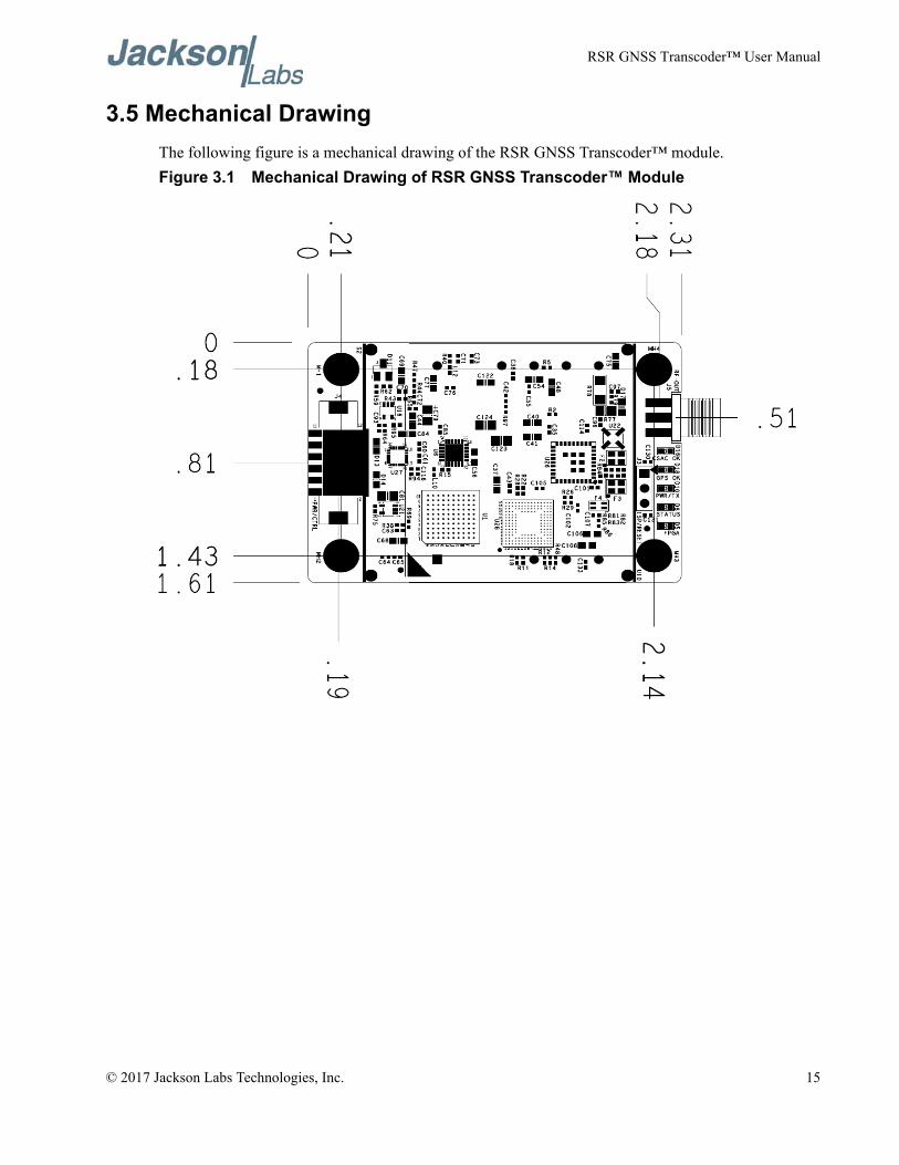
3.5 Mechanical DrawingThe following figure is a mechanical drawing of the RSR GNSS Transcoder™ module.Figure 3.1 Mechanical Drawing of RSR GNSS Transcoder™ Module
© 2017 Jackson Labs Technologies, Inc. 15
RSR GNSS Transcoder™ User Manual
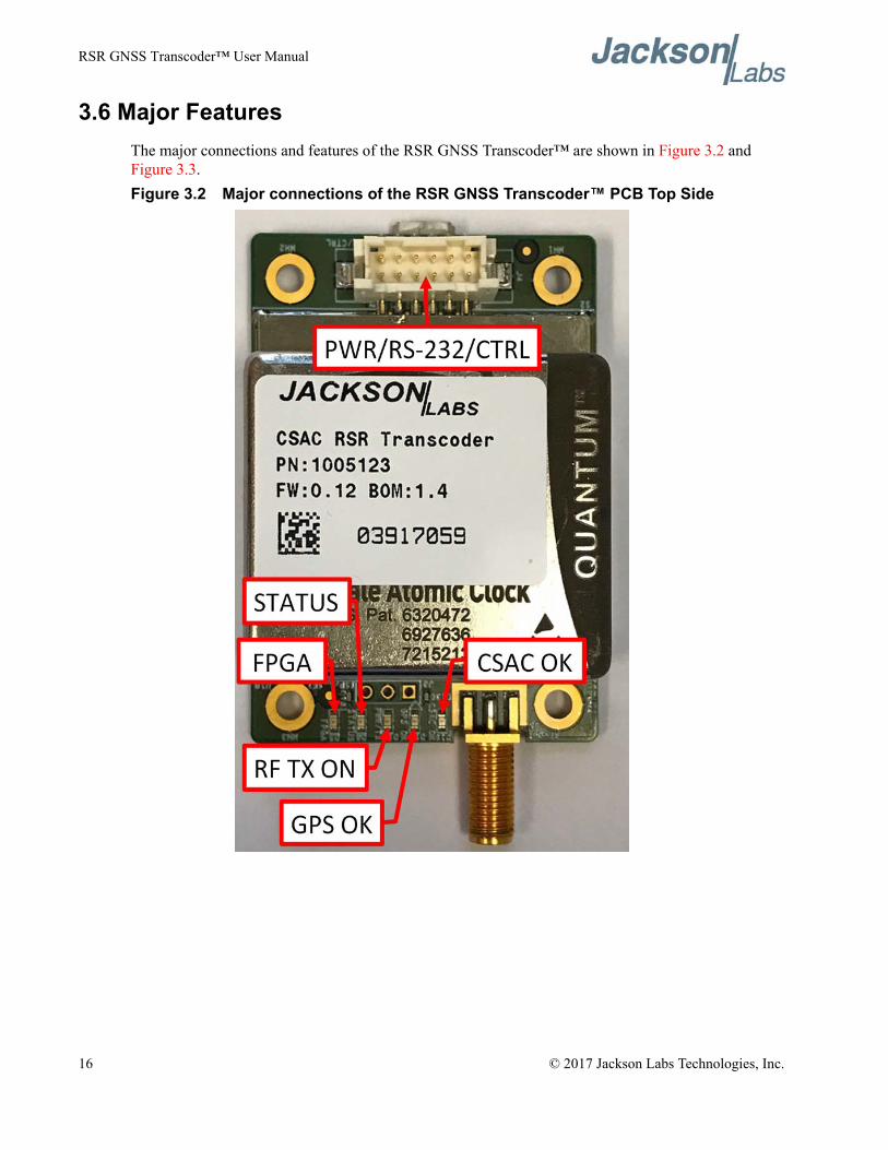
3.6 Major FeaturesThe major connections and features of the RSR GNSS Transcoder™ are shown in Figure 3.2 and Figure 3.3.Figure 3.2 Major connections of the RSR GNSS Transcoder™ PCB Top Side
16 © 2017 Jackson Labs Technologies, Inc.
RSR GNSS Transcoder™ User Manual
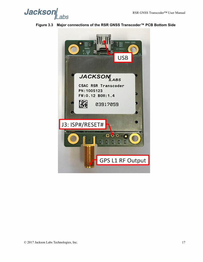
Figure 3.3 Major connections of the RSR GNSS Transcoder™ PCB Bottom Side
© 2017 Jackson Labs Technologies, Inc. 17
RSR GNSS Transcoder™ User Manual
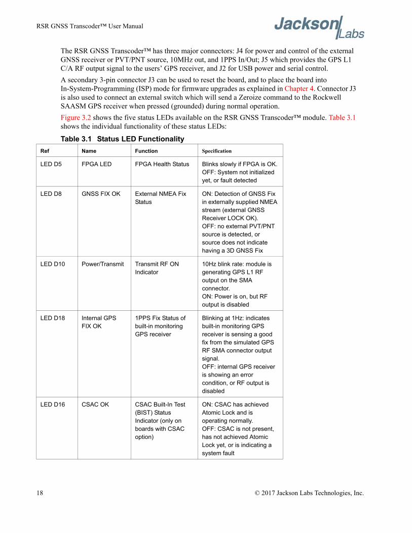
The RSR GNSS Transcoder™ has three major connectors: J4 for power and control of the external GNSS receiver or PVT/PNT source, 10MHz out, and 1PPS In/Out; J5 which provides the GPS L1 C/A RF output signal to the users’ GPS receiver, and J2 for USB power and serial control.A secondary 3-pin connector J3 can be used to reset the board, and to place the board into In-System-Programming (ISP) mode for firmware upgrades as explained in Chapter 4. Connector J3 is also used to connect an external switch which will send a Zeroize command to the Rockwell SAASM GPS receiver when pressed (grounded) during normal operation.Figure 3.2 shows the five status LEDs available on the RSR GNSS Transcoder™ module. Table 3.1 shows the individual functionality of these status LEDs:
Table 3.1 Status LED FunctionalityRef Name Function Specification
LED D5 FPGA LED FPGA Health Status Blinks slowly if FPGA is OK.OFF: System not initialized yet, or fault detected
LED D8 GNSS FIX OK External NMEA Fix Status
ON: Detection of GNSS Fix in externally supplied NMEA stream (external GNSS Receiver LOCK OK).OFF: no external PVT/PNT source is detected, or source does not indicate having a 3D GNSS Fix
LED D10 Power/Transmit Transmit RF ON Indicator
10Hz blink rate: module is generating GPS L1 RF output on the SMA connector.ON: Power is on, but RF output is disabled
LED D18 Internal GPS FIX OK
1PPS Fix Status of built-in monitoring GPS receiver
Blinking at 1Hz: indicates built-in monitoring GPS receiver is sensing a good fix from the simulated GPS RF SMA connector output signal.OFF: internal GPS receiver is showing an error condition, or RF output is disabled
LED D16 CSAC OK CSAC Built-In Test (BIST) Status Indicator (only on boards with CSAC option)
ON: CSAC has achieved Atomic Lock and is operating normally.OFF: CSAC is not present, has not achieved Atomic Lock yet, or is indicating a system fault
18 © 2017 Jackson Labs Technologies, Inc.
RSR GNSS Transcoder™ User Manual
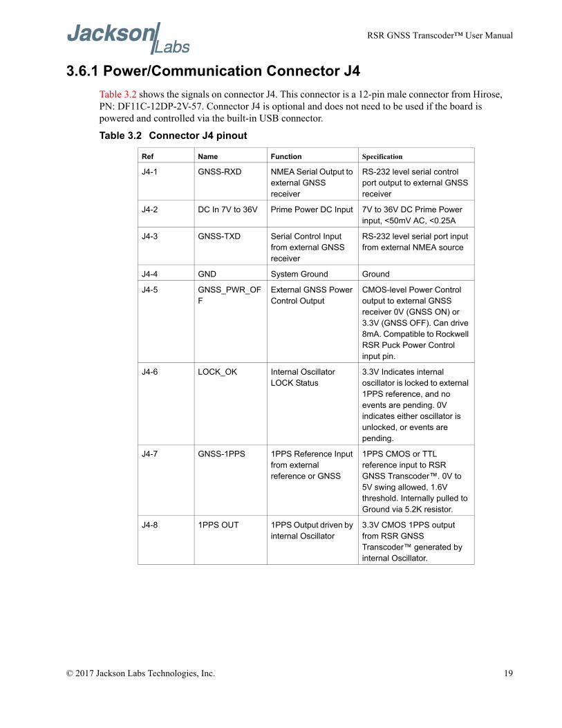
3.6.1 Power/Communication Connector J4Table 3.2 shows the signals on connector J4. This connector is a 12-pin male connector from Hirose, PN: DF11C-12DP-2V-57. Connector J4 is optional and does not need to be used if the board is powered and controlled via the built-in USB connector.
Table 3.2 Connector J4 pinout
Ref Name Function Specification
J4-1 GNSS-RXD NMEA Serial Output to external GNSS receiver
RS-232 level serial control port output to external GNSS receiver
J4-2 DC In 7V to 36V Prime Power DC Input 7V to 36V DC Prime Power input, <50mV AC, <0.25A
J4-3 GNSS-TXD Serial Control Input from external GNSS receiver
RS-232 level serial port input from external NMEA source
J4-4 GND System Ground Ground
J4-5 GNSS_PWR_OFF
External GNSS Power Control Output
CMOS-level Power Control output to external GNSS receiver 0V (GNSS ON) or 3.3V (GNSS OFF). Can drive 8mA. Compatible to Rockwell RSR Puck Power Control input pin.
J4-6 LOCK_OK Internal Oscillator LOCK Status
3.3V Indicates internal oscillator is locked to external 1PPS reference, and no events are pending. 0V indicates either oscillator is unlocked, or events are pending.
J4-7 GNSS-1PPS 1PPS Reference Input from external reference or GNSS
1PPS CMOS or TTL reference input to RSR GNSS Transcoder™. 0V to 5V swing allowed, 1.6V threshold. Internally pulled to Ground via 5.2K resistor.
J4-8 1PPS OUT 1PPS Output driven by internal Oscillator
3.3V CMOS 1PPS output from RSR GNSS Transcoder™ generated by internal Oscillator.
© 2017 Jackson Labs Technologies, Inc. 19
RSR GNSS Transcoder™ User Manual
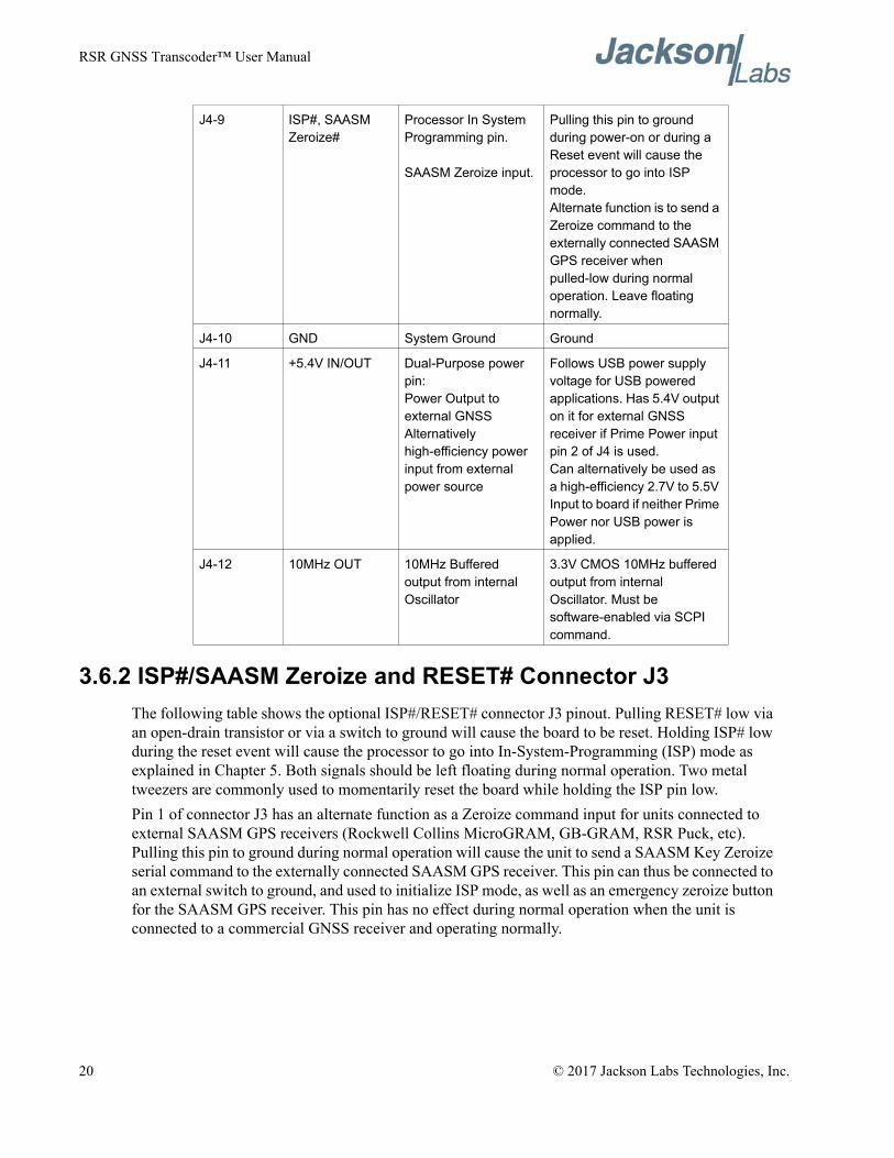
3.6.2 ISP#/SAASM Zeroize and RESET# Connector J3The following table shows the optional ISP#/RESET# connector J3 pinout. Pulling RESET# low via an open-drain transistor or via a switch to ground will cause the board to be reset. Holding ISP# low during the reset event will cause the processor to go into In-System-Programming (ISP) mode as explained in Chapter 5. Both signals should be left floating during normal operation. Two metal tweezers are commonly used to momentarily reset the board while holding the ISP pin low.Pin 1 of connector J3 has an alternate function as a Zeroize command input for units connected to external SAASM GPS receivers (Rockwell Collins MicroGRAM, GB-GRAM, RSR Puck, etc). Pulling this pin to ground during normal operation will cause the unit to send a SAASM Key Zeroize serial command to the externally connected SAASM GPS receiver. This pin can thus be connected to an external switch to ground, and used to initialize ISP mode, as well as an emergency zeroize button for the SAASM GPS receiver. This pin has no effect during normal operation when the unit is connected to a commercial GNSS receiver and operating normally.
J4-9 ISP#, SAASM Zeroize#
Processor In System Programming pin.
SAASM Zeroize input.
Pulling this pin to ground during power-on or during a Reset event will cause the processor to go into ISP mode.Alternate function is to send a Zeroize command to the externally connected SAASM GPS receiver when pulled-low during normal operation. Leave floating normally.
J4-10 GND System Ground Ground
J4-11 +5.4V IN/OUT Dual-Purpose power pin:Power Output to external GNSSAlternatively high-efficiency power input from external power source
Follows USB power supply voltage for USB powered applications. Has 5.4V output on it for external GNSS receiver if Prime Power input pin 2 of J4 is used.Can alternatively be used as a high-efficiency 2.7V to 5.5V Input to board if neither Prime Power nor USB power is applied.
J4-12 10MHz OUT 10MHz Buffered output from internal Oscillator
3.3V CMOS 10MHz buffered output from internal Oscillator. Must be software-enabled via SCPI command.
20 © 2017 Jackson Labs Technologies, Inc.
RSR GNSS Transcoder™ User Manual
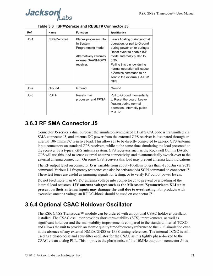
Table 3.3 ISP#/Zeroize and RESET# Connector J3
3.6.3 RF SMA Connector J5Connector J5 serves a dual purpose: the simulated/synthesized L1 GPS C/A code is transmitted via SMA connector J5, and antenna DC power from the external GPS receiver is dissipated through an internal 186 Ohms DC resistive load. This allows J5 to be directly connected to generic GPS Antenna input connectors on standard GPS receivers, while at the same time simulating the load presented to the receiver by a typical GPS antenna system. GPS receivers such as the Rockwell Collins DAGR GPS will use this load to sense external antenna connectivity, and to automatically switch-over to the external antenna connection. On some GPS receivers this load may prevent antenna fault indications.The RF output level on connector J5 is variable from about -100dBm to less than -125dBm via SCPI command. Various L1 frequency test tones can also be activated via SCPI command on connector J5. These test tones are useful as jamming signals for testing, or to verify RF output power levels.Do not feed more than 6V DC antenna voltage into connector J5 to prevent overloading of the internal load resistors. 12V antenna voltages such as the Microsemi/Symmetricom XLI units present on their antenna inputs may damage the unit due to overheating. For products with excessive antenna voltage an RF DC-block should be used on connector J5.
3.6.4 Optional CSAC Holdover OscillatorThe RSR GNSS Transcoder™ module can be ordered with an optional CSAC holdover oscillator installed. The CSAC oscillator provides short-term-stability (STS) improvements, as well as significant holdover and thermal-stability improvements compared to the standard internal TCXO, and allows the unit to provide an atomic quality time/frequency reference to the GPS simulation even in the absence of any external NMEA/GNSS or 1PPS timing references. The internal TCXO is still used as a phase-noise and spur-filter oscillator for the CSAC as it is tightly phase-locked to the CSAC via an analog PLL. This improves the phase-noise of the 10MHz output on connector J4 as
Ref Name Function Specification
J3-1 ISP#/Zeroize# Places processor into In System Programming mode.
Alternatively zeroizes external SAASM GPS receiver.
Leave floating during normal operation, or pull to Ground during power-on or during a Reset event to enable ISP mode. Internally pulled to 3.3V.Pulling this pin low during normal operation will cause a Zeroize command to be sent to the external SAASM GPS.
J3-2 Ground Ground Ground
J3-3 RST# Resets main processor and FPGA
Pull to Ground momentarily to Reset the board. Leave floating during normal operation. Internally pulled to 3.3V
© 2017 Jackson Labs Technologies, Inc. 21
RSR GNSS Transcoder™ User Manual
well as the overall simulation signal quality. The CSAC (as well as the TCXO on units without a CSAC) can be automatically disciplined to an external 1PPS reference source which is typically a user-supplied GNSS receiver, and the unit will go into holdover mode automatically when the external GNSS receiver stops producing a 1PPS signal due to loss of GNSS lock etc. Both the 1PPS output and the 10MHz output on connector J4 are generated by the internal TCXO locked to the optional CSAC, and are thus highly-stable and accurate while exhibiting very low phase-noise. The built-in CSAC is steered by the same algorithms used on the popular JLT CSAC GPSDO modules, and provides a highly-stable atomic reference platform. As an interesting side-note: the internally-generated 1PPS pulse and NMEA date/time information is also available to the USB port DCD interrupt and serial port, and thus the unit can act as a standard PVT reference for NTP servers under Linux using the industry-standard GPSD driver.In the absence or failure of the CSAC on the module the internal TCXO is automatically controlled by a built-in 24 bit DAC and optionally disciplined to an external 1PPS reference via JLT’s GPSDO disciplining algorithms. Switchover between the software-driven TCXO DAC and the analog PLL locking the TCXO to the CSAC is automatic. The built-in CSAC oscillator can also be powered-down manually through an SCPI command to reduce overal power consumption. The unit will automatically revert to TCXO-only disciplining in the event the CSAC is powered-down, or fails to operate properly for any reason.Operation with the optional CSAC oscillator allows the unit to act as a time-transfer device to any external GPS receiver. In stable conditions the CSAC can have drift rates of less than 2us per day, thus allowing highly-accurate time-keeping when operating in GPS-denied environments, or when generating IS-GPS-250A compatible Pseudolite signals for example. Accrued phase and frequency errors inside the CSAC oscillator can be calibrated-out automatically and within a handful of minutes by simply feeding-in an accurate and stable 1PPS reference source to the module.For testing and evaluation the CSAC can be manually steered (CSAC:STEER xx command), and steering values can be manually stored inside the CSAC NVRAM by issueing the CSAC:STEER:LATCH ONCE command. Please see the CSAC GPSDO user manual for additional details on the operation and monitoring capabilities of the built-in CSAC GPSDO sub-system.
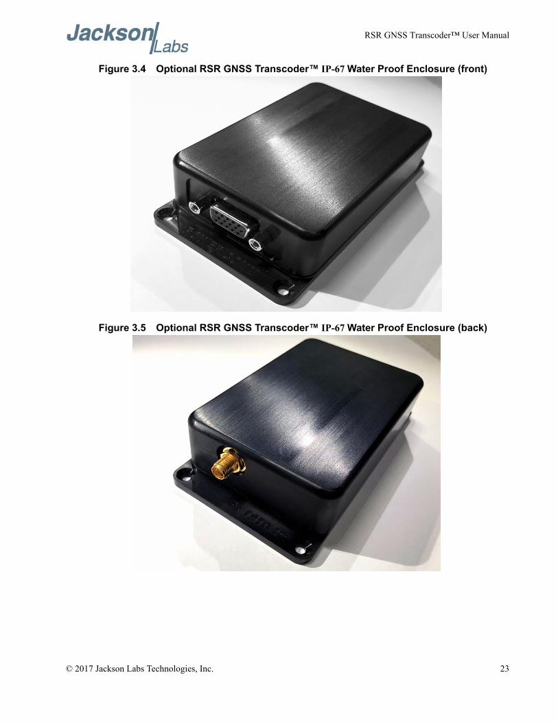
3.7 Optional IP67 Water-Proof enclosureThe RSR GNSS Transcoder™ can be ordered with a ruggedized IP67 water-proof machined anodized-aluminum enclosure. The unit can be operated inside the enclosure with or without the optional CSAC oscillator. The internal USB connector pins and the pins of connector J4 are brought out of the enclosure on a water-tight DB-15 female connector, and the RF SMA output connector is available in the back of the enclosure. Four strong magnets on the bottom of the enclosure allow mounting the unit on a vehicle roof or other metal surfaces, while four mounting holes allow a more permanent mounting with screws or bolts. Rockwell Collins makes available a cable harness upon demand to glue-lessly connect the Rockwell Collins RSR SAASM or M-Code puck receivers to the RSR GNSS Transcoder™. Legacy GPS antennae can thus simply be replaced by the Rockwell RSR Puck connected to the RSR GNSS Transcoder™, and an optional 5V (USB), or 7V to 36V (12V nominal) power source connected to the cable harness. The RF output of the unit would simply be connected to the legacy equipments’ RF antenna input connector on top of the vehicle in this scenario. A USB break-out cable can be used for software upgrades and configuration. The following images show the optional RSR GNSS Transcoder™ IP-67 water-proof enclosed unit:
22 © 2017 Jackson Labs Technologies, Inc.
RSR GNSS Transcoder™ User Manual
Figure 3.4 Optional RSR GNSS Transcoder™ IP-67 Water Proof Enclosure (front)
Figure 3.5 Optional RSR GNSS Transcoder™ IP-67 Water Proof Enclosure (back)
© 2017 Jackson Labs Technologies, Inc. 23
RSR GNSS Transcoder™ User Manual
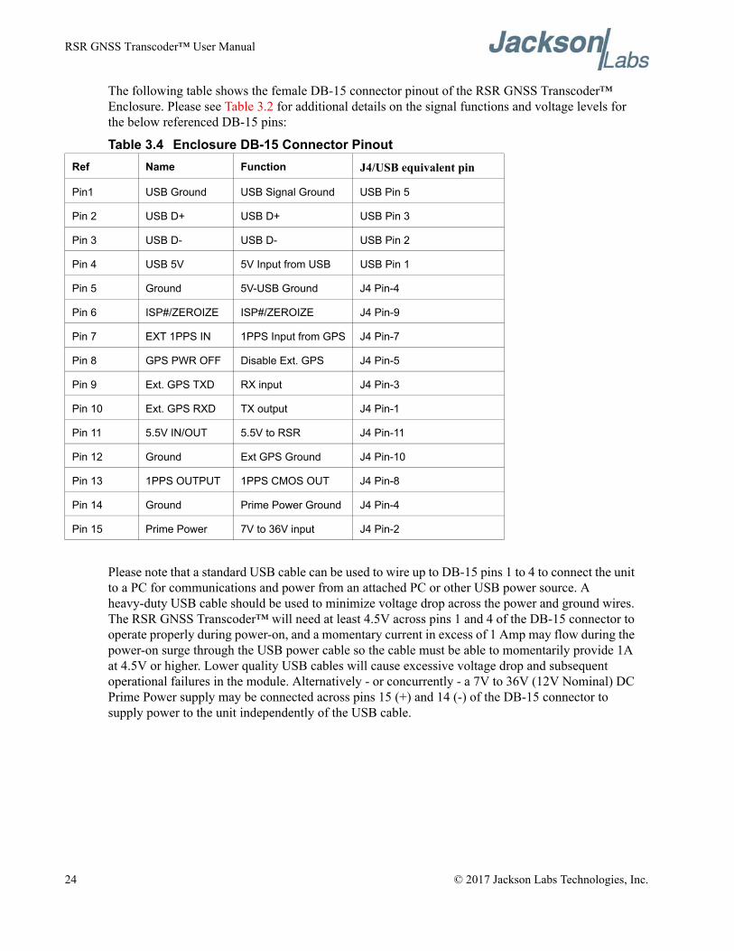
The following table shows the female DB-15 connector pinout of the RSR GNSS Transcoder™ Enclosure. Please see Table 3.2 for additional details on the signal functions and voltage levels for the below referenced DB-15 pins:
Table 3.4 Enclosure DB-15 Connector Pinout
Please note that a standard USB cable can be used to wire up to DB-15 pins 1 to 4 to connect the unit to a PC for communications and power from an attached PC or other USB power source. A heavy-duty USB cable should be used to minimize voltage drop across the power and ground wires. The RSR GNSS Transcoder™ will need at least 4.5V across pins 1 and 4 of the DB-15 connector to operate properly during power-on, and a momentary current in excess of 1 Amp may flow during the power-on surge through the USB power cable so the cable must be able to momentarily provide 1A at 4.5V or higher. Lower quality USB cables will cause excessive voltage drop and subsequent operational failures in the module. Alternatively - or concurrently - a 7V to 36V (12V Nominal) DC Prime Power supply may be connected across pins 15 (+) and 14 (-) of the DB-15 connector to supply power to the unit independently of the USB cable.
Ref Name Function J4/USB equivalent pin
Pin1 USB Ground USB Signal Ground USB Pin 5
Pin 2 USB D+ USB D+ USB Pin 3
Pin 3 USB D- USB D- USB Pin 2
Pin 4 USB 5V 5V Input from USB USB Pin 1
Pin 5 Ground 5V-USB Ground J4 Pin-4
Pin 6 ISP#/ZEROIZE ISP#/ZEROIZE J4 Pin-9
Pin 7 EXT 1PPS IN 1PPS Input from GPS J4 Pin-7
Pin 8 GPS PWR OFF Disable Ext. GPS J4 Pin-5
Pin 9 Ext. GPS TXD RX input J4 Pin-3
Pin 10 Ext. GPS RXD TX output J4 Pin-1
Pin 11 5.5V IN/OUT 5.5V to RSR J4 Pin-11
Pin 12 Ground Ext GPS Ground J4 Pin-10
Pin 13 1PPS OUTPUT 1PPS CMOS OUT J4 Pin-8
Pin 14 Ground Prime Power Ground J4 Pin-4
Pin 15 Prime Power 7V to 36V input J4 Pin-2
24 © 2017 Jackson Labs Technologies, Inc.
RSR GNSS Transcoder™ User Manual
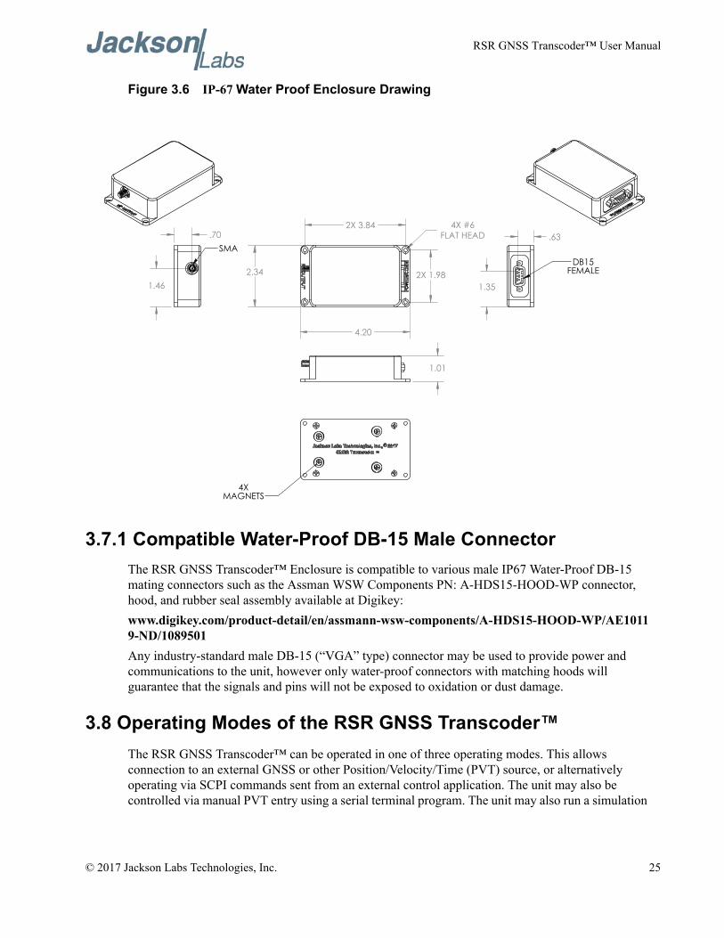
Figure 3.6 IP-67 Water Proof Enclosure Drawing
3.7.1 Compatible Water-Proof DB-15 Male ConnectorThe RSR GNSS Transcoder™ Enclosure is compatible to various male IP67 Water-Proof DB-15 mating connectors such as the Assman WSW Components PN: A-HDS15-HOOD-WP connector, hood, and rubber seal assembly available at Digikey:www.digikey.com/product-detail/en/assmann-wsw-components/A-HDS15-HOOD-WP/AE10119-ND/1089501Any industry-standard male DB-15 (“VGA” type) connector may be used to provide power and communications to the unit, however only water-proof connectors with matching hoods will guarantee that the signals and pins will not be exposed to oxidation or dust damage.
3.8 Operating Modes of the RSR GNSS Transcoder™The RSR GNSS Transcoder™ can be operated in one of three operating modes. This allows connection to an external GNSS or other Position/Velocity/Time (PVT) source, or alternatively operating via SCPI commands sent from an external control application. The unit may also be controlled via manual PVT entry using a serial terminal program. The unit may also run a simulation
© 2017 Jackson Labs Technologies, Inc. 25
RSR GNSS Transcoder™ User Manual
totally autonomously either from an internally-stored time-stamped vector file (feature to be released in late 2017), or a stationary position fix.
3.8.1 Transcoding with External GNSS ReceiverAny GNSS receiver, INS or other device capable of providing GGA and RMC sentence NMEA output at 1Hz can be used as a PVT source for transcoding. Transcoding with precise time and UTC phase transfer also requires a 1PPS from the transcoding receiver. When configured in transcoding mode, the RSR GNSS Transcoder™ will wait and look for NMEA data at 9600 and/or 38400 baud and the presence of a 1PPS input after power-on. When NMEA data is found, the RSR GNSS Transcoder™ will wait for a valid position fix and a stable 1PPS output at which time it will enable the GPS L1 RF output and begin transcoding. The unit may also optionally be configured to transcode NMEA PVT information without an external 1PPS reference signal being present.The RSR GNSS Transcoder™ will continue to update the position and synchronize precise timing with the 1PPS reference input until the external GNSS receiver indicates a loss of lock. The RSR GNSS Transcoder™ can operate in three different user-selectable holdover modes when the external receiver indicates a loss of GNSS fix. The holdover mode is controlled with the SIMulation:HOLDover:MODE <ON|OFF|LIMIT> command as described in Section 4.3.4 .ON mode: This mode will cause the RF output to remain on by propagating time using either the internal high stability TCXO or optional CSAC atomic clock as a timing reference, and applying the currently selected filter mode to the transcoded position. Both clocks can be used for precise time transfer to the target receiver, with the CSAC being able to maintain precise timing for longer holdover periods. The ON mode is best used to provide timing holdover to the target GPS receiver and when guaranteed position accuracy during holdover is not required. When using the ON mode and the position filter mode is set to INS, the transcoded position continues to be updated based on a dead reckoning solution from the internal INS. The INS solution accuracy will degrade as time passes, and is only to be used as an approximate positioning reference. See Section 3.8.8 for more details on configuring the filtering mode.JLT has devised a way to communicate fix status of the GPS simulator entirely through the RF antenna feed by artificially enabling and disabling certain PRN numbers in the simulation output or attenuating certain PRN numbers. This allows a target GPS receiver to be used without any modification, while at the same time transferring information about the simulated PVT fix quality. Thus it is possible to determine if the GNSS Transcoder™ is in holdover mode or receiving valid external GNSS reference fixes for example.Two holdover indicate modes configured with the SIMulation:HOLDover:INDicate <SV32 | HIGHEST | OFF> command are available to communicate to the target GPS receiver that the transcoder is operating in holdover mode. In SV32 mode, PRN 32 is enabled only when the holdover state is active. So when PRN 32 is being tracked by the target GPS receiver, the target GPS receiver can determine if the holdover state is on or off. The target system can use this information to determine that the RSR GNSS Transcoder™ is itself in CSAC/TCXO/INS holdover mode. For example, when the target system detects a holdover condition by sensing the presense of PRN32 in the simulator RF output, it may no longer use the position information as it is known at that time that the position is just estimated, but the system may continue to use the 1PPS phase reference provided by the target receiver for a user-determined period of time based on the holdover performance of the RSR GNSS Transcoder™’s oscillator holdover performance. The SV32 mode indicates the holdover state by using an extra satellite that is not used in the constellation so the accuracy of the PVT solution in the target receiver is not affected. However, some target GPS receivers may not
26 © 2017 Jackson Labs Technologies, Inc.
RSR GNSS Transcoder™ User Manual
consistently track the SV32 signal because this satellite is not part of the normal GPS constellation. If this is the case, then the HIGHEST holdover indicate mode can be used instead.In the HIGHEST holdover indicate mode the unit decreases the RF signal amplitude of the highest elevation satellite by 6dB to indicate that the holdover state is active. This difference in signal strength can be easily distinguished in the target receiver’s reported SNR numbers since the highest elevation satellite will have a reported SNR signficantly below the average reported for other satellites. In most cases, the target receiver can continue to use this satellite in the PVT solution. However, the accuracy of the PVT solution may be affected due to the reduction in signal strength of one satellite.When the external GNSS receiver obtains a GPS fix, the transcoded position quickly moves within defined maximum dynamics to the new input position and the time will quickly skew to the precise time obtained by the input 1PPS. See Section 3.8.8 for the commands that control the maximum dynamics that are applied to the RF simulator output when the position has to be “jumped” from one second to the other such as would happen when the external reference GNSS receiver has re-aquired a PVT fix after a longer GNSS-denied period.OFF mode: The off mode will cause the RF output to turn off within about 4 seconds of the external GNSS receiver losing valid position data. When this happens, the target GPS receiver will also lose a GPS lock so that the timing holdover performance depends upon the characteristics of the target GPS receiver system. This mode also guarantees that the target receiver will not output invalid PVT data since it will indicate that no GPS fix is available. When the external GNSS receiver obtains a GPS fix, the transcoded position will move immediately to the new input position and the time will jump to the precise time from the external 1PPS reference, or from the internal oscillator when no 1PPS reference is present. This mode is typically only used with the TCXO variant of the module, as the CSAC time and phase information would not be available to a target GPS receiver when the module goes into holdover/flywheel mode.LIMIT mode: The LIMIT mode will cause the transcoded RF output to remain on for a defined length of time after the external GNSS receiver indicates loss of valid position data. The holdover time limit is configured using the SIMulation:HOLDover:LIMIT command as described in Section 4.3.6 . When the holdover limit has been reached the RF output turns off and the target receiver will lose its GPS lock. The LIMIT mode is useful when the holdover timing stability of the RSR GNSS Transcoder™ should be used for a limited time to prevent excessive timing errors from being transfered to the target receiver. When the external GNSS receiver once again indicates valid PVT data, the RSR GNSS Transcoder™’s holdover recovery behavior will be similar to the ON holdover mode if the RF output was still enabled at the time the holdover ended, and it will be similar to the OFF holdover mode if the RF output had already been disabled due to reaching the holdover time threshold limit. This could be losely compared to a GPS cold- and warm-start.
3.8.2 Detecting and Configuring External GNSS ReceiverIn addition to accepting standard NMEA input from the external GNSS receiver, the RSR GNSS Transcoder™ can also control special functions on Rockwell Collins RSR SAASM Puck and Microgram SAASM GPS receivers as well as uBlox 5 through uBlox 8 GPS/GNSS receivers through serial configuration data sent from the RS-232 port to the external GNSS receiver. The type of receiver is configured with the GPS:TYPE command as described in Section 4.10.1 . The default configuration is AUTO where the receiver type is automatically queried and detected after power-on or reset. The following sections describe the special configuration and monitoring features available with the Rockwell and Ublox receivers.
© 2017 Jackson Labs Technologies, Inc. 27
RSR GNSS Transcoder™ User Manual
3.8.2.1 Connecting a Rockwell Collins RSR SAASM Puck and/or MicroGRAM SAASM GPSThe RSR GNSS Transcoder™ will initialize and control externally-connected Rockwell Collins RSR SAASM Puck and MicroGRAM SAASM Receivers via the RS-232 serial port. For these receivers to communicate with the RSR GNSS Transcoder™, the NMEA protocol including input messages must be enabled manually in their configuration by Rockwell Collins by ordering the NMEA versions of these products. The Rockwell GPS receivers will have only ICD-153 interfacing enabled by default, and the NMEA capability must be configured by Rockwell Collins at their factory upon user-request. Also the 1PPS output mode should be configured to UTC during assembly-configuration of the receiver. Please contact Jackson Labs Technolgies, Inc. for additional information regarding the required receiver configuration. Special features that are available with the Rockwell Collins SAASM receivers include Y-Tracking status, keyfill status, anti-spoofing status, zeroize, 1PPS quantization error and DAGR assisted warm-start mode control and status. See Section 4.10 for details of the supported SAASM GPS relevant SCPI commands. Jackson Labs Technologies, Inc. has partnered with Rockwell Collins to create a special timing-enabled version of the internal MicroGRAM and GB-GRAM SAASM firmware. This software version has been security-approved and is only available to JLT customers. It is required to be used on the Rockwell Collins GPS SAASM receiver to achieve the best timing performance from the unit and thus recommended (but not required) on systems using the CSAC oscillator disciplining option.
3.8.2.2 Connecting a uBlox GNSS ReceiverThe RSR GNSS Transcoder™ will also control products from uBlox, viz. uBlox generations 5 through 8 GPS and multi-GNSS receivers. The RSR GNSS Transcoder™ will work with both standard and fixed-position timing receiver versions of the uBlox 5 through 8. The uBlox receiver should start up at the default baud rate of 9600, and the RSR GNSS Transcoder™ will configure the baud rate of the uBlox GNSS receiver to 38400 automatically via the built-in RS-232 serial port. The RSR GNSS Transcoder™ communicates with the uBlox receivers using both the NMEA output and uBlox Binary input and output commands. The RSR GNSS Transcoder™ also configures the uBlox receiver’s 1PPS output for optimum settings for the GPSDO operation of the RSR GNSS Transcoder™. The entire uBLox GNSS receiver configuration process is transparent to the user.Special features available with the uBlox 5 through 8 GNSS receivers include a Fixed Position/ Auto Survey mode, automatic and manual dynamic Kalman filter settings, ECEF position and velocity, antenna delay setting, jamming level monitoring, concurrent GNSS reception capability (uBlox-8 and later), and 1PPS quantization error monitoring/compensation. See Section 4.10 for details on the supported SCPI commands.
3.8.3 Manually entering Lat/Long/Height Simulation CoordinatesWhen the RSR GNSS Transcoder™ is operating in simulator mode, it can use position information provided from a JLT-custom motion command language or from a fixed position entered through SCPI commands. The fixed position to be simulated as entered through SCPI commands is stored in non-volatile memory and will be retained through a power cycle. The SIMulation:POSition:LLH and SIMulation:POSition:ECEF commands are used to enter or query the current fixed position in Latitiude/Longitude/Height or Earth Centered Earth Fixed (ECEF) coordinates. When the simulation
28 © 2017 Jackson Labs Technologies, Inc.
RSR GNSS Transcoder™ User Manual
is started with either manual commands (Section 4.3.2 ) or in simulation mode from power up (Section 4.3.3 ), the previously set position will be used for the simulated position. If the fixed position is changed while the simulation is running, the simulation position will quickly move to the new position, limited only by the maximum dynamics configured in the SIMulation:POSition:FILTer SCPI commands as described starting in Section 4.3.11 . When the simulation position approaches the fixed position, the speed will reduce at the maximum acceleration rate, and the simulated position will stop at the new fixed position. This synthesized movement from the old position to the new position is done to prevent the GPS receiver filters from loosing lock during the transition.For example, the following commands will start a fixed position simulation and then change only the altitude from 500 to 2000 meters so that the simulated position changes to the new altitude with the specified maximum velocity and acceleration:
SIM:MODE MANUAL[optionally: SIM:POS:LLH ,,500] (it is assumed that the previously simulated height was set to 500m)SIM:POS:LLH 36,-115,500SIM:POS:FILTER:MODE DYNASIM:POS:FILTER:VMAX 100SIM:POS:FILTER:AMAX 0.5gSIM:COMMAND STARTSIM:POS:LLH ,,2000
The simulated position will now move from 500 meters and stop at the newly commanded altitude of 2000 meters. Any additional SIM:POS:LLH commands sent cause motion with the maximum defined dynamics until the new position is reached.
3.8.4 Simulating from Internally Stored Motion CommandsThe custom JLT motion command language defines a sequence of positioning commands that are stored in non-volatile memory and executed sequentially during a simulation when the simulation mode is set to SIM and the simulation position mode is set to MOTION with the “SIMulation:POSition:MODE <FIXED | MOTION>” command. This mode is typically used by the JLT Windows application available in late 2017. Alternatively these commands can be manually entered through the serial port as needed. The motion vectors are stored using the SIMulation:POSition:MOTION:WRITE command which causes the SCPI interface to enter command entry mode. In command entry mode, one command per line is received until an END command is received. Details on the command entry including the syntax of commands are available starting in Section 4.3.18 .The available commands include:
Reference - Set initial position, heading and speedStraight - Straight motion for specified durationAccelerate - Straight motion, change speed specified amount for specified durationTurn - Heading change at specified latural accelerationClimb - Change in height at specified climb rate with start and end lateral accelerationWaypoint - Waypoint position, final heading and speed.
© 2017 Jackson Labs Technologies, Inc. 29
RSR GNSS Transcoder™ User Manual
Combined Accelerate/Turn - Specify heading change, lateral acceleration and change in speed.
Combination Acclerate/Turn/Climb - Specify change in heading, lateral acceleration, change in height, height rate and start and end lateral acceleration
Halt - Set final position and stopEnd - End sequence of motion commands
3.8.5 Configuring the GPS ConstellationThe default GPS constellation for simulation and transcoding is a synthesized 30 satellite constellation optimized for position and timing accuracy. In most cases, this synthesized constellation should be used, however there are cases where a specific user-selected GPS constellation needs to be simulated. In these cases, the user can provide the subframe data for either the ephemeris or almanac for each satellite.The SIMulation:LNAV:SELect <SYNTH | USER> command sets the source of the ephemeris and ionospheric correction data. With the USER option, the stored ephemeris and ionospheric data from the SIM:LNAV commands will be used directly in the simulation. Care must be taken so that the time of validity for the ephemeris is within 0 to 2 hours after the simulation time. For simulations longer than 2 hours the ephemeris data must be updated periodically and at least every two hours for the target GPS receiver to operate correctly and with a continuous smooth PVT output.As of the release of this manual the USER mode is not yet supported in the firmware. Future releases of the RSR GNSS Transcoder™ firmware will included support for the USER mode and SIM:LNAV commands. Also the Jackson Labs Technologies, Inc. Windows simulator application available end of 2017 will provide the tools to convert standard RINEX ephemeris and Yuma almanac data to subframe data that is accepted by the RSR GNSS Transcoder™.
3.8.5.1 Uploading Almanac and Ephemerides DataTo provide ephemeris data to be used during the simulation enter the following command:
SIMulation:LNAV:EPHemeris <prn> <subframe> <word> <data> for up to 32 satellites PRN numbers. See Section 4.3.48 for a complete description of the required subframes and words for each PRN.Similarly, ionospheric correction data is provided with the following command:
SIMulation:LNAV:IONosphere <subframe> <word> <data>See Section 4.3.47 for a complete description of this command.All of the required words in a subframe must be received together since the entire subframe is assembled in volatile memory. To store the completed subframe in non-volatile memory for use in the simulation enter the SIM:LNAV:WRITE command.As of the release of this manual the USER mode and the SIM:LNAV commands are not yet supported in the firmware. Future releases of the RSR GNSS Transcoder™ firmware will included support for the USER mode and SIM:LNAV commands. Also the Jackson Labs Technologies, Inc. Windows simulator application available end of 2017 will provide the tools to convert standard RINEX ephemeris and Yuma almanac data to subframe data that is accepted by the RSR GNSS Transcoder™.
30 © 2017 Jackson Labs Technologies, Inc.
RSR GNSS Transcoder™ User Manual
3.8.6 Excluding Space Vehicles from SimulationFor most applications, all of the simulated GPS satellites should be enabled for best position and timing accuracy. However in some cases, the simulation with one or more satellites disabled is desired. The satellites can be disabled by GPS satellite PRN number using the SIMulation:SV:EXCLude command. For example to remove SV 2 and SV 10 enter the commands:
SIM:SV:EXCL 2SIM:SV:EXCL 10
To query the current list of excluded satellites enter the command:SIM:SV:EXCL?
which will respond with the list of excluded satellites followed by spaces:2 10
To re-enable removed satellites, use the SIM:SV:EXCL command with negative SV PRN numbers:SIM:SV:EXCL -2SIM:SV:EXCL -10
3.8.7 Satellite Elevation Mask AngleTo enable all satellites that are used by the target receiver, the elevation mask angle should be set on the RSR GNSS Transcoder™ to be equal or less than the elevation mask angle configured on the receiver. Please consults the documentation for the target receiver for its elevation mask angle settings.The elevation mask angle on the RSR GNSS Transcoder™ causes only satellites above the specified elevation angle to be enabled and visible in the simulated RF output. To set the mask angle, use the SIMulation:SV:MASK command. For example, to specify a 10 degree mask angle use the command:
SIM:SV:MASK 10The angle can be configured to enable satellites below the horizon with a negative mask angle (-90 to +90 degree range), however most receivers will not allow configuration of the mask angle below the horizon and the RSR GNSS Transcoder™ can simulate only up to a total of 10 satellites at any time. The number of satellites visible above the horizon rarely exceeds 10 when using a typical 30 space vehicle orbital configuration.
3.8.8 Using the Position Filtering and INS CapabilitiesPosition filtering on the RSR GNSS Transcoder™ is required for several reasons and three filtering modes are provided to meet different requirements. Position Filtering can be enabled and selected via the following command:
SIMulation:POSition:FILTer:MODE <OFF | DYNAMIC | INS >The default position filtering mode is DYNAMIC, where the simulated position follows the input position as closely as possible but the simulated position dynamics are limited to a defined maximum speed, acceleration and jerk. For each 100th update interval, the input position is compared with the current simulated position. The velocity, acceleration and jerk required to move to the input position are compared with the defined maximum velocity accerelation and jerk and limits to the movement
© 2017 Jackson Labs Technologies, Inc. 31
RSR GNSS Transcoder™ User Manual
to the next simulated position are placed so that these maximum dynamics are not exceeded. Limits are also placed on the velocity so that the simulated position will stop on and not overshoot the input position due to the acceleration and jerk limits.Dynamic filtering is useful to match the expected dynamics of the target receiver and avoid loss of lock due to large jumps in position or velocity--both of which can result in loss of GPS satellite tracking. Dynamic filtering is also useful when simulating with fixed position mode so that the simulated position will move to the new position with limited dynamics, which is useful for creating simple dynamic simulations.In the Dynamic position filtering mode, limits are placed on the maximum velocity, acceleration and jerk to move towards the newly received reference position as quickly as possible. The set of commands for configuring the maximum dynamics include:
SIMulation:POSition:FILTer:VMAXSIMulation:POSition:FILTer:AMAXSIMulation:POSition:FILTer:JMAX
The target receiver also often has configuration options for maximum expected dynamics. In transcoding applications, the reference PVT input should be expected to have a maximum dynamics because of the configuration of the PVT source and the maximum dynamics expected in the given application. So in general for transcoding applications, the dynamics should be in the order:
Application expected dynamics <= PVT source maximum dynamics<= RSR GNSS Transcoder™ maximum dynamics <= Target receiver maximum dynamics
In the INS position filtering mode and transcoding position mode, the onboard IMU provides additional filtering and interpolation between input position as well as short periods of dead reckoning in the cases of short (<60 second) loss of the input PVT source. This is useful in interpolating the external GNSS reference 1-position-fix-per-second to 10Hz or higher to provide a smoothly varying RF simulation output to the target receiver. The INS unit will interpolate and create intermediate fixes at a 10Hz rate in-between two externally-supplied 1Hz PVT NMEA reference fixes.The maximum dynamics expected by the INS system is also affected by maximum velocity, acceleration and jerk commands used to control the Dynamic filtering mode. Additional INS/IMU features are provided with the SCPI GYRO commands.In the filtering OFF mode, the input transcoded position or input fixed position is applied immediately. This may be useful for some applications where it is OK for fixed position input to immediatly jump from one position to the next. However this can cause tracking problems and conditions of loss-of-lock in the target receiver that can be difficult or impossible for the target receiver to recover from. So it is highly recommended that either Dynamic or INS position filtering be enabled for most usage scenarios.Position filtering on the RSR GNSS Transcoder™ can be configured using the following command:
SIMulation:POSition:FILTer:MODE <OFF | DYNAMIC | INS >as described in Section 4.3.11 . The filtering does not affect the simulated position when playing back motion commands since the motion commands have built-in definitions for dynamics that override the position filtering settings.
32 © 2017 Jackson Labs Technologies, Inc.
RSR GNSS Transcoder™ User Manual
3.8.9 Adjusting the RF Output Power LevelThe RF output level is typically equal for all transmitting satellites. The output power in dBm is set with the OUT:POWer command as described in Section 4.5.3 . The nominal received power for each satellite using a typical passive antenna in the real world with a clear view of the sky and the satellite in a high-noon position is about -125dBm to -130 dBm. A higher power level can be provided by the RSR GNSS Transcoder™ to mimick the precense of an active amplified antenna system that many target GPS receivers are expecting. The controllable output power range available is typically -105dBm to -125dBm.The output power command is able to compensate for either an external amplifier or external attenuators configured with the OUT:OFFset command as described in Section 4.5.4 . Any range of amplification or attenuation can be specified as an offet so that the OUT:POW command can be used to select the final, absolute RF power available to the GPS target receiver. This value also affects the controllable range with the OUT:POWer command, allowing for a wider range of control.The following example will set the output power per satellite at -130 dBm and compensate for an external 10dB attenuator in-between the RF output and the GPS target receiver:
OUT:OFFset -10dBOUT:POW -130dBm
Because of the compensation for the 10 dB attenuator, the output power at the SMA connector of the RSR GNSS Transcoder™’s is offset to be 10 dB higher and thus exit the unit at -120 dBm. Note that the desired output power of -130dBm would be outside the controllable range of -105dBm to -125dBm and thus not be possible without the use of an external attenuator.Likewise, the following example will set the output power to -75dBm using an external 30dB amplifier:OUT:OFFset 30dBOUT:POW -75dBmThe signal would exit the RF SMA connector at -105dBm, then be amplified by the external amplifier to -75dBm. Again, note that the desired output power of -75dBm would be outside the controllable range without the external amplfier.
3.8.10 Enabling RF Test-Tone OutputFor calibrating power levels, jamming testing, or receiver RF front-end testing, the RSR GNSS Transcoder™ can generate various digitally synthesized RF Test-Tones. GPS RF simulation seizes when a Test-Tone output is enabled. The output level of the test signal is adjustable using the OUT:POWer command. The achievable test-tone output power range is about 19dB higher than the equivalent C/A code modulated GPS channel power.The output test tone is configured using the command:
OUTput:TEST <OFF | SWEEP | TONE | TWOTONE | RAND>Where the test signal options are:
SWEEP - Continuous wave tone that is swept over several MHz around 1,575.42MHzTONE - Continuous Wave (CW) tone at 1575.42MHzTWOTONE - Two CW tones centered around 1575.42 MHz
© 2017 Jackson Labs Technologies, Inc. 33
RSR GNSS Transcoder™ User Manual
RAND - Random noise centered around 1575.42 MHzNormally the output tone should be set to OFF to enable GPS RF signals.The following command is an example showing how to configure the RSR GNSS Transcoder™ as a CW jammer for mixing with another simulated or live-sky GPS signal:OUTput:TEST TONEPlease note that transmissions in the GPS L1 band are regulated by government decree and that test tone and GPS L1 RF output from the RSR GNSS Transcoder™ should not be transmitted from a radiating antenna without permission from the FCC or other local regulating organization.
3.8.11 Configuring the simulated Time and DateWhen operating in Simulation mode, the system can be configured to start the simulation using a fixed specified time. The module can also use continuous time as provided by a reference input PVT source. When using a fixed start time with repeated simulations, the target GPS receiver may require a manual reset or cold-start to recognized the correct simulated time, and to properly receive the GPS signals. This may happen because the target receiver does not expect the GPS time to jump backwards between simulation runs. Cell-phone GPS receivers are notorious for knowing the current UTC time and refusing to receive a time/date in the past or further out in the future without a complete cold-start of the receiver. Using the continuous time sentences from a PVT source reduces the need to cold-start the target receiver as the simulation will accurately transmit UTC time/date to the target receiver, and thus fulfill any assumptions the target receiver would have about the current time/date.The simulation time mode is set with the SIMulation:TIME:MODE <ASSIGNed | CONTinuous> command as detailed in Section 4.3.29 .When using the ASSIGNed mode, the unit uses the time and date specified in the commands:
SIMulation:TIME:START:TIMESIMulation:TIME:START:DATE
Assigning a date and time for the simulation is useful in simulating future leap-seconds, future GPS week 1023 roll-over events, or any type of date/time anomaly in the target GPS receiver.
3.8.12 Simulating Leap Second EventThe UTC correction parameters that define the current and future leap second offset as well as fractional second offsets between GPS and UTC time are configured with the SIM:TIME:UTC... commands as detailed in Section 4.3.35 and later. The parameters that need to be set to simulate a leap second event are the start time and date as described in Section 3.8.11 , and the IS-GPS-200-defined UTC parameters DELTATLS, WNLSF, DN and DELTATLSF. The parameter DELTATLS is the current number of seconds difference between UTC and GPS time. WNLSF is the week number of the leap second event and DN is the day number (1 through 7) of the event. The actual leap second event for positive leap seconds occurs immediately after 23:59:59 on the day defined by WNLSF and DN. Finally, DELTATLSF is the final UTC offset in seconds after the leap second event.The RSR GNSS Transcoder™ also provides a simplified method of setting the UTC correction parameters with the SIM:TIME:LEAP... commands. The SIM:TIME:LEAP:ACCumulated
34 © 2017 Jackson Labs Technologies, Inc.
RSR GNSS Transcoder™ User Manual
command sets the currently accumulated UTC to GPS offset in seconds before any pending leap seconds. The SIM:TIME:LEAP:DATE command sets the date of a current or previously pending leap second. And the SIM:TIME:LEAP:DURation command sets the duration of the next pending leap second.As an example, to simulate the the December 31, 2016 leap second event with the simulation beginning 30 minutes before the event, enter the following commands:
SIM:MODE MANUALSIM:TIME:START:TIME 23,30,00SIM:TIME:START:DATE 2016,12,31SIM:TIME:LEAP:ACC 17SIM:TIME:LEAP:DATE 2016,12,31SIM:TIME:LEAP:DUR 61SIM:COMMAND START
The simulation should be started with sufficient time for the target receiver to download the UTC correction parameters which can take up to 12.5 minutes.
3.8.13 Simulating 1023 Week Number RolloverUsing the start time- and date parameters described in Section 3.8.11 , the start time can be selected to simulate a week number rollover event that some GPS receivers have difficulty handling properly. For example, to simulate the upcoming April 6, 2019 week number rollover event, enter the following commands:
SIM:MODE MANUALSIM:TIME:START:TIME 23,30,00SIM:TIME:START:DATE 2019,4,6SIM:COMMAND START
The simulation will start 30 minutes before the event and continue indefininately. You can end the simulation with the SIM:COMMAND STOP command.
3.8.14 Simulating for GPS SpoofingThe RSR GNSS Transcoder™ can generate an GPS L1 output that is synchronized to live-sky GPS signals. These live-sky and simulated signals can be combined together with a low-cost passive RF combiner/splitter so that a target receiver will start tracking the simulated signals instead of the live signals depending on relative power levels between the two signal sources. Using both user-uploaded ephemeris and ionospheric correction data as well as time sychronized from an external GPS receiver, it is possible to mix the RSR GNSS Transcoder’s RF output with a live-sky GPS signal for spoofing simulations of live GPS signals. The external GPS receiver should be connected with NMEA and 1PPS input to the RSR GNSS Transcoder™. Care must be taken to avoid re-broadcasting simulated RF signals through the live sky antenna, and this is usually accomplished by using passive RF combiners and GPS antennae with good rejection and isolation.The following commands will configure the simulation mode, simulation time and the fixed (spoofed) position:
© 2017 Jackson Labs Technologies, Inc. 35
RSR GNSS Transcoder™ User Manual
SIM:MODE MANUALSIM:TIME:MODE CONTSIM:POS:LLH 36,-115,500
The spoofed position in the SIM:POS:LLH command should be nearby the position of the antenna (within 1000 km) so that the simulated and spoofed satellites are visible at the same time. The current ephemeris and ionospheric correction data can be uploaded with the SIM:LNAV... commands described starting in Section 4.3.47 . This process could be automated if the raw subframe data were available from a receiver tracking live-sky signals.Next, confirm that the system time has been updated with the current gps system time with the command:
PTIME?If the time and date lines from the query output show the current time and date then the system time is synchronized.Finally, the source for the navigation data and the initial RF output power are set, and the simulation is started with the following commands:
SIM:LNAV:SELect USEROUT:POWer -125dBmSIM:COMMAND START
During the spoofing test, the output power is increased from -125dBm with the OUT:POWer command until the output power is greater than the mixed live-sky signals. Without an external amplifier the output power can be set as high as -105dBm. An external amplifier may be required in some cases if power levels above -105dBm are needed.At some point the target receiver will start tracking the spoofed signals instead of the live-sky signals and the target receiver’s reported position will jump to the simulated spoofed position. Having the spoofed position very close (<100m) from the antenna position may reduce the output power required to pull the target receiver away from the live-sky signals. This behavior is very dependent on the design of the target receiver, and the relevant RF power levels.
3.8.15 Monitoring the optional CSAC OscillatorThe RSR GNSS Transcoder™ with optional CSAC oscillator contains an integrated CSAC GPSDO module with the same monitoring and control features that the JLT CSAC GPSDO module provides. The following example CSAC status output is returned in response to the CSAC? query:
RS232: OKSTEER: -35STATUS: 0ALARM: 0x0000MODE: 0x0040CONTRAST: 3608LASER CURRENT: 0.98TCXO VOLTAGE: 1.549
36 © 2017 Jackson Labs Technologies, Inc.
RSR GNSS Transcoder™ User Manual
DC SIGNAL LEVEL: 1.17HEAT PACKAGE: 9.34TEMPERATURE: 38.57SN: 1607CS06361FIRMWARE REV: 1.09LIFETIME: 740POWER: ON
On units without the optional CSAC oscillator The RSR GNSS Transcoder™ will discipline its internal TCXO to an external 1PPS reference when provided. Before the CSAC achieves atomic lock which typically takes less than 3 minutes after power-on, the system timing uses the internal TCXO as the timing and frequency reference. In the event that the CSAC GPSDO fails to obtain an atomic lock or fails during operation after obtaining atomic lock, the internal TCXO will be used for system timing instead. To enable calibration of the built-in TCXO-based GPSDO or to reduce the overall power consumption, the CSAC can also be manually disabled with the CSAC:POWer command which will power-down the internal CSAC and revert to TCXO disciplining only. The ON/OFF power status of the CSAC is output on the last line of the CSAC? query response as seen above.
3.8.16 Monitoring the External and Internal GNSS ReceiversAn optional external GPS receiver can provide a PVT serial data stream to be transcoded and simulated using the 1PPS timing reference for time synchronization and internal TCXO/CSAC oscillator disciplining. This PVT data stream can be monitored using the standard GPS SCPI subsystem common to many JLT GPSDO products with commands such as SERV?, SYST:STAT?, GPS? and others. Details of each GPS command are available in Section 4.10.3 .The RSR GNSS Transcoder™ also includes an internal GNSS receiver for monitoring the transcoded or simulated GPS RF signals for accuracy, power level, and correctness. The status of this internal GNSS receiver is monitored through the INTGPS SCPI subsystem that has many of the same commands available as the GPS SCPI subsystem. It is possible to send the 1Hz NMEA output stream of the internal GPS monitoring receiver to the USB serial port via SCPI commands. Details of the various different INTGPS command are available starting in Section 4.11.1 .
3.8.16.1 External Rockwell Microgram and RSR FeaturesThe RSR GNSS Transcoder™ supports special features when an external Rockwell Collins Microgram or Rockwell Collins RSR SAASM receivers with updated, custom JLT firmware are connected. These features include DAGR Pass-Through mode and SAASM key-fill status monitoring.A DAGR Pass-Through hot-start assisted mode is available when a DAGR is connected to the COM2 interface on the external Microgram or RSR. This mode allows hot-starting the MicroGRAM or RSR receiver by automatically transferring almanac, ephemeris, time, date, and position data from the external DAGR to the MicroGRAM/RSR. The DAGR Pass-Through mode can be controlled through the RSR GNSS Transcoder™’s SCPI interface. In DAGR Pass-Through mode the PVT data including the 1PPS reference from an external DAGR device is used in place of the PVT data generated by the MicroGRAM or RSR. Using a DAGR that already has a GPS fix, the SAASM HD
© 2017 Jackson Labs Technologies, Inc. 37
RSR GNSS Transcoder™ User Manual
CSAC GPSDO can immediately provide valid PVT data through the SCPI interface and discipline the CSAC oscillator.DAGR Pass-Through mode is especially useful when the MicroGRAM or RSR receiver does not have valid almanac data which could take up to 12.5 minutes to download from the GPS satellites before a GPS fix and valid UTC time is available. The DAGR pass-through mode is typically used when the RSR GNSS Transcoder™ is deployed in a dismounted application, and the user is sitting inside of a shielded vehicle such as a troop transporter etc, and cannot receive GNSS signals themselves. In this case the vehicle DAGR with its externally mounted antenna can provide the necessary PVT solution and almanac/ephemerides etc to enable continuous operation and disciplining of the RSR GNSS Transcoder™ inside the vehicle for as long as the user’s MicroGRAM or RSR receiver is connected to the DAGR DB-15 connector, and the DAGR is receiving valid GPS fixes. The DAGR pass-through mode requires the JLT-specific Rockwell Collins NMEA firmware load on the external MicroGRAM or RSR, and this firmware can only be loaded at the Rockwell Collins factory and is only available to JLT customers.The GPS:DAGR:MODE command described in Section 4.10.32 enables and disables the DAGR Pass-Through mode. The GPS:DAGR:PVTstate? query command described in Section 4.10.35 returns the status of the DAGR Pass-Through mode.When in DAGR Pass-Through mode, the external DAGR can also provide Hot Start data to the MicroGRAM or RSR, so the MicroGRAM or RSR can immediately obtain a GPS fix. Hot start data includes precise time, GPS alamanc and ephemeris data, and current position. Once the SAASM HD CSAC GPSDO is in DAGR Pass-Through mode, a Hot-Start transfer is initiated on the DAGRs user menu.The SAASM key, Y tracking status and key zeroizing of an external Microgram or RSR receive can also be monitored and controlled through the RSR GNSS Transcoder™’s GPS:SASTAT... commands. Details on the parameters that can be monitored and the zeroize function are available in Section 4.10.36 through Section 4.10.46 .An externally connected Rockwell Collins MicroGRAM, or RSR SAASM receiver may also be zeroized by using pin 1 of connector J3. Grounding pin 1 of connector J3 during normal operation through a switch etc will initiate a zeroize command to be sent to the externally connected SAASM GPS receiver, and is thus useful as an emergency zeroize feature.
38 © 2017 Jackson Labs Technologies, Inc.
RSR GNSS Transcoder™ User Manual
SCPI Command Reference
4.1 IntroductionThe RSR GNSS Transcoder™ can typically be used in one of three operating modes. The following SCPI commands are used to control and monitor these operating modes. The available modes are:
1) Static position simulation with only time/date advancing2) Dynamic position simulation with position, velocity, heading, and time/date advancing based on external commands, or following motion vectors stored in internal NV memory3) Real-time PVT transcoding where the RF output simulation follows externally-provided 1Hz PVT NMEA reference strings as well as externally provided 1PPS reference UTC timing pulses
The RSR GNSS Transcoder™ includes a USB connector (U2) for accessing the SCPI (Standard Commands for Programmable Instrumentation) subsystem by using a host system terminal program such as TeraTerm or HyperTerminal. By default the terminal settings are 115200, 8N1, no flow-control. The SCPI interface can be used to query status of the unit, generate NMEA compatible output sentences, or setup and control simulations and transcoding.There are a number of commands that can be used as listed below. Many of these are identical or similar to Symmetricom/Agilent 58503A commands. To get a listing of the available commands, send the HELP? query. This will return a list of all the available commands and their syntax.Commands can be entered in either caps or lower-case, and only the characters listed in caps in the below command reference need to be typed-in.Additional information regarding the SCPI protocol syntax can be found on the following web site:
http://www.ivifoundation.org/scpi/A basic familiarity with the SCPI protocol is recommended when reading this chapter.As many setup commands use standard GPS nomenclature, JLT recommends review and consideration of the GPS standard specification IS-GPS-200 available here:
http://www.gps.gov/technical/icwg/
© 2017 Jackson Labs Technologies, Inc. 39
RSR GNSS Transcoder™ User Manual
As a Quick-Start, the user may want to try sending the following commands to the unit:sim?syst:stat?help?gps?ptim?sync?
4.2 General SCPI Commands
4.2.1 *IDN?This query outputs an identifying string. The response will typically show the following information:<company name>, <model number>, <serial number>, <firmware revision>
4.2.2 HELP?This query returns a list of the commands available for the RSR GNSS Transcoder™.
4.3 Simulation SubsystemThe Simulation subsystem groups all of the commands associated with controlling the simulation and transcoding features. The list of commands supported is the following:
SIMulation:MODE <AUTO|MANUAL|SIM|TRANSCODE>SIMulation:STATe?SIMulation:HOLDover:MODE <ON|OFF|LIMIT>SIMulation:HOLDover:STATe?SIMulation:HOLDover:LIMIT [5,86400]SIMulation:HOLDover:INDicate <SV32 | HIGHEST | OFF>SIMulation:POSition?SIMulation:POSition:LLH <lat,long,alt>SIMulation:POSition:ECEF <x,y,z>SIMulation:POSition:FILTer?SIMulation:POSition:FILTer:MODE <OFF|DYNAMIC|INS>SIMulation:POSition:FILTer:LLH?SIMulation:POSition:FILTer:ECEF?SIMulation:POSition:FILTer:VMAX <1.0,600.0>
40 © 2017 Jackson Labs Technologies, Inc.
RSR GNSS Transcoder™ User Manual
SIMulation:POSition:FILTer:AMAX <0.1,20.0>SIMulation:POSition:FILTer:JMAX <100.0,1000.0>SIMulation:POSition:MOTION:WRITE <int> [1,100]SIMulation:POSition:MOTION:READ <int> [1,100]SIMulation:POSition:MOTION:START <int> [0,100]SIMulation:TRACe <int> [0,255]SIMulation:SV?SIMulation:SV:VIEW?SIMulation:SV:EXCLude [1, 32; -1, -32]SIMulation:SV:MASK [0.0,90.0]SIMulation:SV:TRACe <int> [0,32]SIMulation:TIME:MODE <ASSIGNed | CONTinuous>SIMulation:TIME:START:TIMESIMulation:TIME:START:DATESIMulation:TIME:LEAPsecond:ACCumulatedSIMulation:TIME:LEAPsecond:DATESIMulation:TIME:LEAPsecond:DURationSIMulation:TIME:UTCoffset:A0SIMulation:TIME:UTCoffset:A1SIMulation:TIME:UTCoffset:DELTATLSSIMulation:TIME:UTCoffset:TOTSIMulation:TIME:UTCoffset:WNTSIMulation:TIME:UTCoffset:DNSIMulation:TIME:UTCoffset:DELTATLSFSIMulation:TIME:UTCoffset?SIMulation:TIME?SIMulation:IONosphere:ASIMulation:IONosphere:BSIMulation:LNAV:IONosphere <subframe> <word> <data>SIMulation:LNAV:EPHemeris <prn> <subframe> <word> <data>SIMulation:LNAV:WRITESIMulation:LNAV:EEPROM?SIMulation:LNAV:ACTIVE?SIMulation:LNAV:SELect <SYNTH | USER>SIMulation?
© 2017 Jackson Labs Technologies, Inc. 41
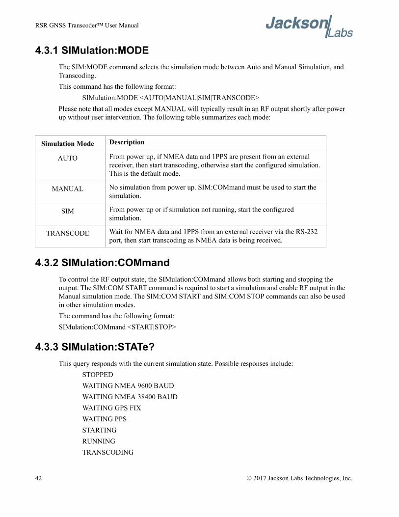
RSR GNSS Transcoder™ User Manual
4.3.1 SIMulation:MODEThe SIM:MODE command selects the simulation mode between Auto and Manual Simulation, and Transcoding.This command has the following format:
SIMulation:MODE <AUTO|MANUAL|SIM|TRANSCODE>Please note that all modes except MANUAL will typically result in an RF output shortly after power up without user intervention. The following table summarizes each mode:
4.3.2 SIMulation:COMmandTo control the RF output state, the SIMulation:COMmand allows both starting and stopping the output. The SIM:COM START command is required to start a simulation and enable RF output in the Manual simulation mode. The SIM:COM START and SIM:COM STOP commands can also be used in other simulation modes.The command has the following format:SIMulation:COMmand <START|STOP>
4.3.3 SIMulation:STATe?This query responds with the current simulation state. Possible responses include:
STOPPEDWAITING NMEA 9600 BAUDWAITING NMEA 38400 BAUDWAITING GPS FIXWAITING PPSSTARTINGRUNNINGTRANSCODING
Simulation Mode Description
AUTO From power up, if NMEA data and 1PPS are present from an external receiver, then start transcoding, otherwise start the configured simulation. This is the default mode.
MANUAL No simulation from power up. SIM:COMmand must be used to start the simulation.
SIM From power up or if simulation not running, start the configured simulation.
TRANSCODE Wait for NMEA data and 1PPS from an external receiver via the RS-232 port, then start transcoding as NMEA data is being received.
42 © 2017 Jackson Labs Technologies, Inc.
RSR GNSS Transcoder™ User Manual
STOPPINGThe STOPPING and STARTING states only occur for 0.1 seconds each when transitioning to and from RUNNING so they are unlikely but possible query responses. The RF output is disabled for all states except for RUNNING and TRANSCODING. The RUNNING or TRANSCODING states are indicated by the RF Active LED blinking at 10Hz. The three WAITING... states are states that occur in the order listed before RUNNING in Transcoding or Auto simulation modes.
4.3.4 SIMulation:HOLDover:MODEThe simulation holdover mode controls the behavior when the external PVT reference indicates position information is invalid while operating in Transcoding simulation mode.The format of this command is:SIMulation:HOLDover:MODE <OFF|ON|LIMIT>When the LIMIT mode is selected, the limit time is specified with the SIM:HOLD:LIMIT command, and the RF output is disabled when the unit reaches the specified holdover time limit described in Section 4.3.6 . The SIM:HOLD:STATe? query responds with the current ON/OFF state of the holdover.
4.3.5 SIMulation:HOLDover:STATe?This command responds with the current ON/OFF state of holdover when operating in transcoding simulation mode. The ON state indicates that the transcoding PVT is based on the local oscillator’s holdover performance and/or the INS dead reckoning if operating in the INS simulation position filter mode.
4.3.6 SIMulation:HOLDover:LIMITThis command specifies the limit in seconds that the holdover state should remain active in the Limit simulation holdover mode. The maximum limit is 1 day or 86400 seconds. Once this holdover limit is reached the RF output will be disabled. For longer holdover periods, use the ON simulation holdover mode.The format of this command is:SIMulation:HOLDover:LIMIT <int> [5,86400]
4.3.7 SIMulation:HOLDover:INDicateThis command selects the holdover indicate mode. The default mode is OFF and one of two holdover indicate modes can be enabled. With the SV32 mode, the unit uses SV PRN 32 as a special satellite to indicate holdover status to a users’ target GPS receiver. This mode encodes the holdover state in a geostationary satellite with PRN 32 above the user’s position. With this holdover indicate mode enabled, PRN 32 is present and can be tracked only when the unit is in a holdover state. The target receiver can sense that PRN 32 is present and communicate the holdover state to the target system. A missing PRN 32 indicates that the unit is running normally, and is not in holdover mode when the PRN32 mode is selected. SV PRN 32 may or may not be present in the simulated RF output if the INDICATE mode is set to OFF.
© 2017 Jackson Labs Technologies, Inc. 43
RSR GNSS Transcoder™ User Manual
In the the HIGHEST holdover indicate mode the unit decreases the signal strength of the highest elevation satellite by 6dB to indicate that the holdover state is active. An amplitude reduction of 6dB should easily be distinguished as a significant reduction in SNR as reported by the target receiver, while still allowing that signal to be tracked and used in the PVT solution. If the highest elevation satellite changes during holdover then the reduced signal strength satellite will also change.The format of this command is:
SIMulation:HOLDover:INDicate <SV32 | HIGHEST | OFF>
4.3.8 SIMulation:POSition:MODEThis command specifies the position mode to be set to either the the Fixed or Motion mode. The fixed position input is detailed in Section 4.3.9 and Section 4.3.10 , while the motion commands are detailed starting in Section 4.3.18 .The format of this command is:SIMulation:POSition:MODE <FIXED | MOTION>
4.3.9 SIMulation:POSition:LLHThis command specifies the current fixed position in Latitude, Longitude and Height (LLH) coordinates. Height is the GPS height or height above the reference ellipsoid and not height above Mean Sea Level (MSL).The format of this command is:
SIMulation:POSition:LLH <lat>,<lon>,<alt>where latitude and longitude are in degrees and altitude is in meters.The fields are separated by comas and up to two of the three parameters are optional. Parameters that are not present are not changed. For example the command:
SIM:POS:LLH ,,1000.0Only sets the simulated altitude to 1000.0 meters leaving the latitude and longitude unchanged from previous settings.The parameters are immediately applied to the position filter input, but the simulated position will change over time depending upon the SIM:POS:FILTER... settings. Only if the simulation position filter mode is set to OFF will the fixed position be applied immediately as the simulated position. If the simulated position filter mode is set to ON the position will traverse from the previous simulated position to the new position with the selected dynamics parameters maximum jerk, maximum acceleration and maximum velocity. See Sections 4.3.14 to 4.3.16 for more details on the dynamics parameters that affect how the unit simulates a transition from one position to the next.
4.3.10 SIMulation:POSition:ECEFThis command specifies the current fixed position in Earth-Centered-Earth Fixed (ECEF) coordinates. The x,y,z parametesr are in meters.The format of this command is:
SIMulation:POSition:ECEF <x,y,z>
44 © 2017 Jackson Labs Technologies, Inc.
RSR GNSS Transcoder™ User Manual
Unlike the SIM:POS:LLH command, all three x,y,z parameters are required.
4.3.11 SIMulation:POSition:FILTer:MODEThis command selects the position filtering mode that affects how the current input position (fixed position or external PVT source) is applied to the current simulation/transcoding position. See Section 3.8.8 for a more detailed description of the filter modes.The format of this command is:SIMulation:POSition:FILTer:MODE <OFF | DYNAMIC | INS>The OFF mode causes the input position to be immediately applied to the simulated position. The DYNAMIC mode moves the simulation position to the input position limiting velocity, acceleration and jerk to maximum values specified in the VMAX, AMAX and JMAX parameters described below. The INS mode uses the internal IMU to aid in filtering the input position and providing dead reckoning capability when operating in Transcoding simulation mode.Both the DYNAMIC and INS modes are configured for maximum dynamics using the VMAX, AMAX and JMAX parameters in the commands described in Sections 4.3.14 , 4.3.15 , and 4.3.16 .As of the release of this manual, only the OFF and DYNAMIC modes are supported. Future releases of the RSR GNSS Transcoder™ firmware will included support for the INS mode.
4.3.12 SIMulation:POSition:FILTer:LLH?This query command responds with the current filtered simulation position in LLH format.
4.3.13 SIMulation:POSition:FILTer:ECEF?This query command responds with the current filtered simulation position in ECEF format.
4.3.14 SIMulation:POSition:FILTer:VMAXThis command specifies the maximum velocity used to configure the position filtering in DYNAMIC and INS position filtering modes. VMAX is then applied to move from the old simulated position to the new simulated position. VMAX is specified in m/sThe format of this command is:SIMulation:POSition:FILTer:VMAX
4.3.15 SIMulation:POSition:FILTer:AMAXThis command specifies the maximum acceleration used to configure the position filtering in DYNAMIC and INS position filtering modes. AMAX is then applied to move from the old simulated position to the new simulated position. AMAX is specified in m/s2.The format of this command is:SIMulation:POSition:FILTer:AMAX
© 2017 Jackson Labs Technologies, Inc. 45
RSR GNSS Transcoder™ User Manual
4.3.16 SIMulation:POSition:FILTer:JMAXThis command specifies the maximum jerk (change in acceleration) used to configure the position filtering in DYNAMIC and INS position filtering modes. JMAX is then applied to move from the old simulated position to the new simulated position. JMAX is specified in m/s3
The format of this command is:SIMulation:POSition:FILTer:JMAX
4.3.17 SIMulation:POSition:FILTer?This query responds with the output from the following SIM:POS:FILT... queries:
SIM:POS:FILT:LLH?SIM:POS:FILT:ECEF?SIM:POS:FILT:MODE?SIM:POS:FILT:VMAX?SIM:POS:FILT:AMAX?SIM:POS:FILT:JMAX?
4.3.18 SIMulation:POSition:MOTION:WRITEThis command writes one motion command in non-volatile memory starting at the storage location line number specified. The format of this command is:SIMulation:POSition:MOTION:WRITE <line>,<command>where <line> is the line number and <command> is the command string. Valid starting line numbers are 1 through 100. The final command must always be END which stops the RF output.When a syntax error occurs with a motion command, an Command Error message is output and that motion command line is ignored. So it is useful to read back the stored commands using the SIM:POS:MOTION:READ command to verify the correct motion commands have been stored.As of the release of this manual Motion Control Language commands are not supported. Future releases of the RSR GNSS Transcoder™ firmware will included support for the Motion Control Language.
4.3.19 SIMulation:POSition:MOTION:READThis command reads back the motion commands stored starting at the specified storage location line until an END command is reached. The output motion commands follow the define motion command syntax in Section 4.3.21 , but the format of the numbers originally entered may have changed as the parameters are stored as floating point numbers and not as the original command text.The format of this command is:SIMulation:POSition:MOTION:READ <line>where <line> is the motion command storage line to start reading back (1 - 100).
46 © 2017 Jackson Labs Technologies, Inc.
RSR GNSS Transcoder™ User Manual
As of the release of this manual Motion Control Language commands are not supported. Future releases of the RSR GNSS Transcoder™ firmware will included support for the Motion Control Language.
4.3.20 SIMulation:POSition:MOTION:STARTThis command sets the start position in the motion command storage for playback during a simulation. The simulation will start at the motion command storage line specified by this commadn and continue until an END command is received or the end of the motion command storage is reached. Also to use the commands stored in the motion command storage, the simulation position mode must be set to MOTION with the SIM:POS:MODE command detailed in Section 4.3.8 .The format of this command is:SIMulation:POSition:MOTION:START <line>where <line> is the motion command storage line to start the simulation (1 - 100).As of the release of this manual Motion Control Language commands are not supported. Future releases of the RSR GNSS Transcoder™ firmware will included support for the Motion Control Language.
4.3.21 Simulation Motion Command LanguageThe Motion Command Language is designed to define the motion trajectory during the simulation using limits and specified dynamics. The dynamics specified in all commands are also subject to the maximum dynamics of the vehicle specified in the Dynamics (DYN) command. Because the Dynamics command can signficantly affect the resulting motion defined by a series of commands, it is highly recommended that the Dynamics command be the first command in a series of Motion Commands. See Section 4.3.21.1 for a description of the Dynamics command. If no Dynamics command is received, the default dynamics parameters are taken from the filter dynamics parameters defined in the SIM:POS:FILTER... commands.The Reference command specifies the starting location, heading and speed of the simulated motion. Again because this affects the remainder of the simulation, it is highly recommended to include the Reference command as the second command in a series of Motion Commands. See Section 4.3.21.2 for a description of the Reference command. If no Reference command is received, the default start position, velocity and heading is the fixed position defined in the SIM:POS:LLH command at zero velocity and heading north (0 degrees).The commands that define the motion are processed sequentially for the required amount of time to complete the commanded motion. These commands include Straight, Accelerate, Turn, Climb, Waypoint, Combined Accelerate/Turn, Combined Accelerate/Turn/Climb and Halt. The motion commands are processed until an END command is reached. At this point the simulation stops and the RF output is disabled.As of the release of this manual Motion Control Language commands are not supported. Future releases of the RSR GNSS Transcoder™ firmware will included support for the Motion Control Language.
© 2017 Jackson Labs Technologies, Inc. 47
RSR GNSS Transcoder™ User Manual
4.3.21.1 DynamicsThe Dynamics command specifies the linear (in the direction of motion) and lateral (orthogonal to the direction of motion) dyanmics limits for all motion. It is recommended that the Dynamics command be the first command in a series of motion commands. The Dynamics command can also be used in the middle of a sequence of Motion Commands to change the vehicle dynamics.The format of this command is:
DYN,<max linear speed>,<max linear accel>,<max linear jerk>,<max lateral accel>,<max lateral jerk>
where<max linear speed> is in m/s,<max linear accel> is in m/s2,<max linear jerk> is in m/s3,<max lateral accel> is in m/s2, and<max lateral jerk> is in m/s3.
4.3.21.2 ReferenceThe Reference command specifies the starting position, velocity and heading. It should be used as the second Motion Command after the Dynamics command in a series of commands.The format of this command is:
REF,<latitude>,<longitude>,<altitude>,<heading>,<speed>where
<latitude> is in +/- degrees,<longitude> is in +/- degrees,<altitude> is in m above the ellipsoid,<heading> is in degrees from north, and<speed> is in m/s.
As of the release of this manual Motion Control Language commands are not supported. Future releases of the RSR GNSS Transcoder™ firmware will included support for the Motion Control Language.
4.3.21.3 StraightThe Straight command specifies level (constant altitude) motion at the current heading and speed for the specified duration. The constant heading / great circle option controls if the path over a long distance will maintain a constant heading and spiral towards the poles, or if the path of the largest circle around the earth is followed. With a constant heading, the heading is only reversed 180 degrees when the north or south pole is reached.The format of this command is:
STR,<duration><C|G>
48 © 2017 Jackson Labs Technologies, Inc.
RSR GNSS Transcoder™ User Manual
where <duration> is in seconds, and C is constant heading and G is great circle.As of the release of this manual Motion Control Language commands are not supported. Future releases of the RSR GNSS Transcoder™ firmware will included support for the Motion Control Language.
4.3.21.4 AccelerateThe Accelerate command specifies a period of level motion at the current heading for the specified duration and positive or negative change in speed.The format of this command is:
ACCEL,<duration>,<change in speed>where <duration> is in seconds and <change in speed> is in m/s.As of the release of this manual Motion Control Language commands are not supported. Future releases of the RSR GNSS Transcoder™ firmware will included support for the Motion Control Language.
4.3.21.5 TurnThe Turn command specifies a period of level motion at the current speed with the specified heading change and lateral acceleration. The combination of the current speed and lateral acceleration will determine the radius of the curve and the time required to complete the turn.The format of this command is:
TURN,<heading change>,<lateral acceleration>where <heading change> is in degrees and <lateral acceleration> is in g (1 g = 9.81 m/s2).As of the release of this manual Motion Control Language commands are not supported. Future releases of the RSR GNSS Transcoder™ firmware will included support for the Motion Control Language.
4.3.21.6 ClimbThe Climb command specifies a period of increase or decrease in altitude at the current constant heading and speed. The parameters specified include the change in height, height rate, lateral acceleration at the start and lateral acceleration at the end.The format of this command is:
CLIMB,<change in height>,<height rate>,<lateral accel start>,<lateral accel end>where
<change in height> is in m,<height rate> is in m/s,<lateral accel start> is in m/s2, and<lateral accel end> is in m/s2.
As of the release of this manual Motion Control Language commands are not supported. Future releases of the RSR GNSS Transcoder™ firmware will included support for the Motion Control Language.
© 2017 Jackson Labs Technologies, Inc. 49
RSR GNSS Transcoder™ User Manual
4.3.21.7 WaypointThe Waypoint command specifies a final position and heading with changes in heading at a specified lateral acceleration at the current speed.The format of this command is:
WAYPT,<latitude>,<longitude>,<altitude>,<final heading>,<lateral acceleration>where
<latitude> is in degrees,<longitude> is in degrees,<altitude> is in m above the ellipsoid,<final heading> is degrees from north,<lateral acceleration> is in m/s2
As of the release of this manual Motion Control Language commands are not supported. Future releases of the RSR GNSS Transcoder™ firmware will included support for the Motion Control Language.
4.3.21.8 Combined Accelerate/TurnThe Combined Accelerate/Turn command specifies motion at a constant altitude at the current speeds that is a combination of accelerating linearly and turning. The parameters specified are heading change, lateral acceleration and change in speed. Since with a constant lateral acceleration, the turning radius is affected by the current speed and the current speed is changing with acceleration, the turning radius will also vary. The time required to complete the motion command is determined by the time required to complete the turn.The format of this command is:
ACCEL-TURN,<heading change>,<lateral acceleration>,<change in speed>where
<heading change> is in degrees,<lateral acceleration> is in g (1 g = 9.81 m/s2), and <change in speed> is in m/s.
As of the release of this manual Motion Control Language commands are not supported. Future releases of the RSR GNSS Transcoder™ firmware will included support for the Motion Control Language.
4.3.21.9 Combined Accelerate/Turn/ClimbThe Combined Accelerate/Turn/Climb command specifies motion that is a combination of accelerating linearly, turning and climbing. The parameters specified are heading change, lateral acceleration, height change, height rate and lateral acceleration.The format of this command is:
ACCEL-TURN-CLIMB,<heading change>,<lateral acceleration>,<height change>,<height rate>,<lateral acceleration>
50 © 2017 Jackson Labs Technologies, Inc.
RSR GNSS Transcoder™ User Manual
where<heading change> is in degrees,<lateral acceleration> is in m/s^2,<height change> is in m,<height rate> is in m/s, and<lateral acceleration> is in m/s^2.
As of the release of this manual Motion Control Language commands are not supported. Future releases of the RSR GNSS Transcoder™ firmware will included support for the Motion Control Language.
4.3.21.10 HaltThe Halt command specifies motion that ends at a specified location. Starting at the current speed and heading, the position changes as quickly as possible to the end location while limited to the maximum dynamics in the Dynamics command.The format of this command is:
HALT,<latitude>,<longitude>,<altitude>where
<latitude> is in degrees,<longitude> is in degrees, and<altitude) is in m above the ellipsoid.
4.3.21.11 EndThe End command specifies the end of a sequence of Motion Commands and stops the simulation and RF output.The format of this command is:
ENDAs of the release of this manual Motion Control Language commands are not supported. Future releases of the RSR GNSS Transcoder™ firmware will included support for the Motion Control Language.
4.3.22 SIMulation:POSition?The SIM:POS? query combines the query responses from the following queries:
SIM:POS:MODE?SIM:POS:LLH?SIM:POS:ECEF?SIM:POS:FILT:LLH?
© 2017 Jackson Labs Technologies, Inc. 51
RSR GNSS Transcoder™ User Manual
4.3.23 SIMulation:TRACeThis command sets the output rate for the periodically generated statistics output for the simulation. The format of this command is:SIMulation:TRACe <interval>where <interval> is the delay in seconds between simulation trace output in seconds. Zero indicates the simulation trace output is disabled.The simulation trace output has the form:
[yy-mm-dd] [hh:mm:ss.sss] [wn] [tow] [update count] [state] [sat count]Where
[yy-mm-dd] and [hh:mm:ss.sss] are the UTC date and time used in the simulation,[wn] and [tow] are the GPS week number and time of week,[update count] is the 10 Hz simulation update count starting at 0,[state] is the simulation state (see table below), and[sat count] is the number of satellites in the simulation.
Below is example output:17-04-27 09:17:35.243 1946 379055.243 6166544 7 10
17-04-27 09:17:36.243 1946 379056.243 6166554 7 10
17-04-27 09:17:37.243 1946 379057.243 6166564 7 10
17-04-27 09:17:38.243 1946 379058.243 6166574 7 10
The state number is a numeric represenation of the state response from the SIM:STATE? query as seen defined in following table:
State SIM:STATE? output
1 STOPPED
2 WAITING NMEA 9600 BAUD
3 WAITING NMEA 38400 BAUD
4 WAITING GPS FIX
5 WAITING PPS
6 STARTING
7 RUNNING
8 STOPPING
52 © 2017 Jackson Labs Technologies, Inc.
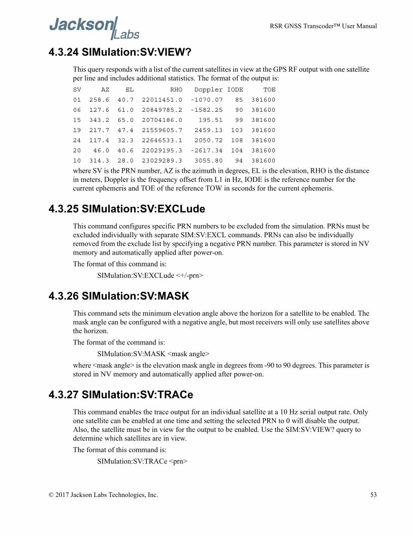
RSR GNSS Transcoder™ User Manual
4.3.24 SIMulation:SV:VIEW?This query responds with a list of the current satellites in view at the GPS RF output with one satellite per line and includes additional statistics. The format of the output is:SV AZ EL RHO Doppler IODE TOE
01 258.6 40.7 22011451.0 -1070.07 85 381600
06 127.6 61.0 20849785.2 -1582.25 90 381600
15 343.2 65.0 20704186.0 195.51 99 381600
19 217.7 47.4 21559605.7 2459.13 103 381600
24 117.4 32.3 22646533.1 2050.72 108 381600
20 46.0 40.6 22029195.3 -2617.34 104 381600
10 314.3 28.0 23029289.3 3055.80 94 381600
where SV is the PRN number, AZ is the azimuth in degrees, EL is the elevation, RHO is the distance in meters, Doppler is the frequency offset from L1 in Hz, IODE is the reference number for the current ephemeris and TOE of the reference TOW in seconds for the current ephemeris.
4.3.25 SIMulation:SV:EXCLudeThis command configures specific PRN numbers to be excluded from the simulation. PRNs must be excluded individually with separate SIM:SV:EXCL commands. PRNs can also be individually removed from the exclude list by specifying a negative PRN number. This parameter is stored in NV memory and automatically applied after power-on.The format of this command is:
SIMulation:SV:EXCLude <+/-prn>
4.3.26 SIMulation:SV:MASKThis command sets the minimum elevation angle above the horizon for a satellite to be enabled. The mask angle can be configured with a negative angle, but most receivers will only use satellites above the horizon.The format of the command is:
SIMulation:SV:MASK <mask angle>where <mask angle> is the elevation mask angle in degrees from -90 to 90 degrees. This parameter is stored in NV memory and automatically applied after power-on.
4.3.27 SIMulation:SV:TRACeThis command enables the trace output for an individual satellite at a 10 Hz serial output rate. Only one satellite can be enabled at one time and setting the selected PRN to 0 will disable the output. Also, the satellite must be in view for the output to be enabled. Use the SIM:SV:VIEW? query to determine which satellites are in view.The format of this command is:
SIMulation:SV:TRACe <prn>
© 2017 Jackson Labs Technologies, Inc. 53
RSR GNSS Transcoder™ User Manual
where <prn> is the satellite PRN number 1 to 32 or 0 for none. This parameter is stored in NV memory and automatically applied after power-on.
4.3.28 SIMulation:SV?This query command will output the query results from the following queries:
SIM:SV:EXCL?SIM:SV:MASK?SIM:SV:TRAC?
4.3.29 SIMulation:TIME:MODEThis command sets the simulation Time mode when running in Simulation mode. When using the ASSIGNED time mode, the simulation will always start with the time and date assigned with the SIM:TIME:START... commands.When using the CONTINUOUS time mode, the simulation will use the current time provided by an external GNSS receiver or UTC time manually set with the PTIME... commands. If the current time has not been set, then the time will be set to the value set by the SIM:TIME:START... commands at the begining of first simulation run. If the simulation is stopped and started again the selected set time will be propgated by the local receiver.The format of this command is:
SIMulation:TIME:MODE <ASSIGNed | CONTinuous>This parameter is stored in NV memory and automatically applied after power-on.
4.3.30 SIMulation:TIME:START:TIMEThis command sets the fixed UTC start time used in the simulation when the simulation Time mode is set to Fixed. The GPS receiver will indicate the this time when the simulation begins. This parameter is stored in NV memory and automatically applied after power-on.The format of this command is:
SIMulation:TIME:START:TIME hh,mm,ss.sss
4.3.31 SIMulation:TIME:START:DATEThis command sets the fixed start date of the simulation when in the simulation Time mode is set to Fixed. The GPS receiver will indicate the this time when the simulation begins. This parameter is stored in NV memory and automatically applied after power-on.The format of this command is:
SIMulation:TIME:START:DATE yyyy,mm,dd
54 © 2017 Jackson Labs Technologies, Inc.
RSR GNSS Transcoder™ User Manual
4.3.32 SIMulation:TIME:LEAPsecond:ACCumulatedThis command sets the current UTC to GPS time offset in seconds and provides a simplified method of setting the UTC correction parameters in the SIM:TIME:UTC... commands. This parameter is stored in NV memory and automatically applied after power-on.When using Transcoding simulation mode or Continuous simulation time mode and the time reference is provided by an external ublox GNSS receiver, the SIMulation:TIME:LEAPsecond parameters are automatically updated when the current and pending leap second data is available. This allows the target GPS receiver to maintain the correct UTC time during a leap second event without manually entering the leapsecond data with the SCPI interface.The format of this command is:
SIMulation:TIME:LEAPsecond:ACCumulated <seconds>
4.3.33 SIMulation:TIME:LEAPsecond:DATEThis command sets the date of the next or previous pending leap second. If the date is after the simulation time, then a leap second is pending and will be simulated. This command provides a simplified method of setting the UTC correction parameters in the SIM:TIME:UTC... commands. This parameter is stored in NV memory and automatically applied after power-on.The format of this command is:
SIMulation:TIME:LEAPsecond:DATE yyyy,mm,dd
4.3.34 SIMulation:TIME:LEAPsecond:DURationThis comand sets the duration of a pending leap second event. Valid values are 59, 60 and 61. If no leap second is pending, the value should be set to 60. This command provides a simplified method of setting the UTC correction parameters in the SIM:TIME:UTC... commands. This parameter is stored in NV memory and automatically applied after power-on.The format of this command is:
SIMulation:TIME:LEAPsecond:DURation <seconds>
4.3.35 SIMulation:TIME:UTCoffset:A0This command specifies the UTC offset parameter A0. This parameter is stored in NV memory and automatically applied after power-on. The parameter is defined in the IS-GPS-200 specification.The format of this command is:
SIMulation:TIME:UTCoffset:A0 <a0>
4.3.36 SIMulation:TIME:UTCoffset:A1This command specifies the UTC offset parameter A1. This parameter is stored in NV memory and automatically applied after power-on. The parameter is defined in the IS-GPS-200 specification.The format of this command is:
© 2017 Jackson Labs Technologies, Inc. 55
RSR GNSS Transcoder™ User Manual
SIMulation:TIME:UTCoffset:A1 <a1>
4.3.37 SIMulation:TIME:UTCoffset:DELTATLSThis command specifies the UTC offset parameter DELTATLS. This parameter is stored in NV memory and automatically applied after power-on. The parameter is defined in the IS-GPS-200 specification.The format of this command is:
SIMulation:TIME:UTCoffset:DELTATLS <deltatls>
4.3.38 SIMulation:TIME:UTCoffset:TOTThis command specifies the UTC offset parameter TOT. This parameter is stored in NV memory and automatically applied after power-on. The parameter is defined in the IS-GPS-200 specification.The format of this command is:
SIMulation:TIME:UTCoffset:TOT <tot>
4.3.39 SIMulation:TIME:UTCoffset:WNTThis command specifies the UTC offset parameter WNT. This parameter is stored in NV memory and automatically applied after power-on. The parameter is defined in the IS-GPS-200 specification.The format of this command is:
SIMulation:TIME:UTCoffset:WNT <wnt>
4.3.40 SIMulation:TIME:UTCoffset:WNLSFThis command specifies the UTC offset parameter WNLSF. This parameter is stored in NV memory and automatically applied after power-on. The parameter is defined in the IS-GPS-200 specification.The format of this command is:
SIMulation:TIME:UTCoffset:WNLSF <wnlsf>
4.3.41 SIMulation:TIME:UTCoffset:DNThis command specifies the UTC offset parameter DN. This parameter is stored in NV memory and automatically applied after power-on. The parameter is defined in the IS-GPS-200 specification.The format of this command is:
SIMulation:TIME:UTCoffset:DN <dn>
4.3.42 SIMulation:TIME:UTCoffset:DELTATLSFThis command specifies the UTC offset parameter DELTATLSF. This parameter is stored in NV memory and automatically applied after power-on. The parameter is defined in the IS-GPS-200 specification.
56 © 2017 Jackson Labs Technologies, Inc.
RSR GNSS Transcoder™ User Manual
The format of this command is:SIMulation:TIME:UTCoffset:DELTATLSF <deltatlsf>
4.3.43 SIMulation:TIME:UTCoffset?This query command returns the response of the following individual queries:
SIM:TIME:UTC:A0?SIM:TIME:UTC:A0?SIM:TIME:UTC:DELTATLS?SIM:TIME:UTC:TOT?SIM:TIME:UTC:WNT?SIM:TIME:UTC:DN?SIM:TIME:UTC:DELTATLSF?
4.3.44 SIMulation:TIME?This query command returns the response of the following individual queries:
SIM:TIME:MODE?SIM:TIME:START:TIME?SIM:TIME:START:DATE?
4.3.45 SIMulation:IONosphere:AThis command configures the a0 through a3 ionospheric parameters that are part of the GPS navigation message. This parameter is stored in NV memory and automatically applied after power-on. The parameter is defined in the IS-GPS-200 specification.The format of this command is:SIMulation:IONosphere:A <a0>,<a1>,<a2>,<a3>
4.3.46 SIMulation:IONosphere:BThis command configures the b0 through b3 ionospheric parameters that are part of the GPS navigation message. This parameter is stored in NV memory and automatically applied after power-on. The parameter is defined in the IS-GPS-200 specification.The format of this command is:
SIMulation:IONosphere:B <b0>,<b1>,<b2>,<b3>
4.3.47 SIMulation:LNAV:IONosphereThe SIM:LNAV:IONosphere command supports the transmission of user-specified ionospheric/UTC correction parameters to the simulator for storage in nonvolatile memory. This command is normally only used by the JLT Windows application available in late 2017.
© 2017 Jackson Labs Technologies, Inc. 57
RSR GNSS Transcoder™ User Manual
The format of this command is:SIMulation:LNAV:IONosphere <subframe> <word> <data>
The following describes the parameters accepted by SIM:LNAV:IONosphere:<subframe> The GPS LNAV subframe number to be addressed by the command. Subframe numbers range from 1 to 5, inclusive, corresponding to the subframes described in IS-GPS-200H Appendix II ("GPS NAVIGATION DATA STRUCTURE FOR LNAV DATA"). Currently the only supported subframe number is 4.<word> The starting word position within the subframe at which the <data> will be written. Supported word positions range from 2 through 9 inclusive, based on an initial index of zero.<data> A series of consecutive 24-bit hexadecimal values to be written to the subframe beginning at the specified <word>. Each 24-bit value consists of six ASCII hex characters (nibbles). No spaces or other characters should appear anywhere within the <data> string. Up to eight 24-bit values may be specified as long as the final <word> position does not exceed the maximum index (9).
An example of this command is:SIM:LNAV:ION 4 2 780502FFFF2603FFFB000003000000034EA8120000000000
4.3.48 SIMulation:LNAV:EPHemerisThe SIM:LNAV:EPHemeris command supports the transmission of user-specified ephemeris parameters to the simulator for storage in nonvolatile memory. This command is normally only used by the JLT Windows application available in late 2017.The format of this command is
SIMulation:LNAV:EPHemeris <prn> <subframe> <word> <data>The following describes the parameters accepted by SIM:LNAV:ION:
<prn> The destination satellite identified by its PRN number (1-32 inclusive).<subframe> The GPS LNAV subframe number to be addressed by the command. Subframe numbers range from 1 to 5, inclusive, corresponding to the subframes described in IS-GPS-200H Appendix II ("GPS NAVIGATION DATA STRUCTURE FOR LNAV DATA"). Supported subframes range from 1 to 3 inclusive. <word> The starting word position within the subframe at which the <data> will be written. Supported word positions for subframes 2 and 3 range from 2 through 9 inclusive, based on an initial index of zero. Supported word positions for subframe 1 are 2, 6, 7, 8, and 9.<data> A series of consecutive 24-bit hexadecimal values to be written to the subframe beginning at the specified <word>. Each 24-bit value consists of six ASCII hex characters (nibbles). No spaces or other characters should appear anywhere within the <data> string. Up to eight 24-bit values may be specified as long as the final <word> position does not exceSed the maximum index (9).
Data written by SIM:LNAV:EPHemeris is stored in a temporary RAM buffer on the simulator platform. Once a complete set of ephemerides have been transmitted to the simulator, they must be committed to EEPROM storage by issuing a SIM:LNAV:WRITE command. An example of this command is:
58 © 2017 Jackson Labs Technologies, Inc.
RSR GNSS Transcoder™ User Manual
SIM:LNAV:EPH 1 1 2 EA1000SIM:LNAV:EPH 1 1 6 00000C0F2A3000FFFD076908SIM:LNAV:EPH 1 2 2 0FFE193088C04D8C00FE13038C40781046A10D74D62A3000SIM:LNAV:EPH 1 3 2 002B6B8EB403FFD7277453311CDD18355339FFA9590F1238
4.3.49 SIMulation:LNAV:WRITEThe SIM:LNAV:WRITE command must be issued to store the ionospheric/UTC parameters and ephemerides most recently uploaded by SIM:LNAV:ION and SIM:LNAV:EPH to nonvolatile (EEPROM) memory. After issuing SIM:LNAV:WRITE, the command SIM:LNAV:SELECT USER may be transmitted to select the uploaded navigation data for simulation.
4.3.50 SIMulation:LNAV:EEPROM?The SIM:LNAV? query returns a list of all ionospheric/UTC and ephemeris parameters stored in EEPROM. The 24-bit words are returned one at a time in the form of individual SIM:LNAV:EPH and SIM:LNAV:ION commands.
4.3.51 SIMulation:LNAV:ACTIVE?The SIM:LNAV? query returns a list of all ionospheric/UTC and ephemeris parameters actively used in the current simulation. The 24-bit words are returned one at a time in the form of individual SIM:LNAV:EPH and SIM:LNAV:ION commands.
4.3.52 SIMulation:LNAV:SELectThe SIM:LNAV:SELect command determines whether internally-generated navigation data or user-uploaded navigation data is used for simulation. The format of this command is:
SIMulation:LNAV:SELect <SYNTH | USER>SYNTH mode selects the internally generated synthesized constellation with circular orbits and precisely 12 hour orbit periods. This is the default mode.USER mode selects the user-uploaded ephemeris and ionospheric/UTC parameters.
4.4 SIMulation?This query command will output the query results from the following queries:SIM:MODE?SIM:STATE?SIM:HOLD:MODE?SIM:HOLD:STATE?SIM:HOLD:LIMIT?SIM:TRACE?
© 2017 Jackson Labs Technologies, Inc. 59
RSR GNSS Transcoder™ User Manual
4.5 Output SubsystemThe commands in the OUTPUT subsystem control various features of the GPS RF and 10MHz output, as well as the built-in RF synthesizer functionality.
4.5.1 OUTput:TESTThis command enables the test signal mode on the SMA RF output that can be used for calibration, spectrum analyzer tests, RF front-end testing, or as a jamming test signal. The signal amplitude of the test signal can typically be set up to -85dBm. The RF power level is set with the OUT:POWer command.The format of this command is:
OUTput:TEST <OFF|SWEEP|TONE|TWOTONE|RAND>The following table describes each of the test modes:
60 © 2017 Jackson Labs Technologies, Inc.
RSR GNSS Transcoder™ User Manual
Test Tone Modes
4.5.2 OUTput:DCBlock <ON|OFF>This command is not supported on the RSR GNSS Transcoder™. The RF output is always DC-coupled and has a 186 Ohms load resistor to ground to simulate an industry-standard GPS antenna load to the target receiver.
4.5.3 OUTput:POWer?This command sets the output power of a single GPS satellite output from the RF output. The valid range is -105dBm to -125 dBm plus the current OUT:OFFset setting. For example if an external 10 dB attenuator is attached to the RF output and OUT:OFFset is set to -10 dB, then the valid range for the OUTput:POWer? command is -115 to -135 dBm. Similarly, if a 10 dB amplifier is connected to the RF output, and the OUT:OFFset is set to +10 dB then the valid range for OUTput:POWer command is -95 to -115 dBm.The OUT:POWer command sets the RF output power per satellite. When N satellites are transmitting, the total RF output power is 10*log10N dB greater.The nominal output power of a live GPS satellite signal at the surface of the earth is typically about -125 dBm, but is often a few dB higher to accomodate for a reduction in power as the satellite ages. Target GPS receivers are also often expecting an amplified antenna, so the output power is typically set higher than -125 dBm for optimum performance of the target GPS receiver.The format of this command is:
OUTput:POWer <power> dBThis parameter is stored in NV memory and automatically applied after power-on.
4.5.4 OUTput:OFFset?This command sets the output power offset to compensate for an external attenuator (negative offset) or amplifier (positive offset). The offset value compensates the value provided to the OUT:POWer command so that the true output power from the RF signal chain including the attenuator or amplifier
Test Mode Description
OFF Default setting for normal GPS signal output
SWEEP Single CW tone, swept +/- 1.023 MHz either side of 1,575.42 MHz over approximately 30 seconds
TONE Single CW tone at 1,575.42 MHz
TWOTONE Two CW tones spaced approximately +/- 50 kHz either side of 1,575.42 MHz. Each tone has 6dB lower amplitude than the OUT:POWER setting.
RAND Baseband (complex) white noise generated by two independent maximal-length shift registers with cycle times of approximately 30 minutes
© 2017 Jackson Labs Technologies, Inc. 61
RSR GNSS Transcoder™ User Manual
matches that of the OUT:POWer setting. The offset also affects the valid range of the OUTput:POWer command setting.
4.5.5 OUTput:10MhzThis command enables/disables the buffered 10 MHz internal oscillator CMOS output on J4 pin 12. By default the output is disabled to reduce noise and power consumption and must be enabled with the ON setting. The format of this command is:
OUTput:10Mhz <ON | OFF>This parameter is stored in NV memory and automatically applied after power-on.
4.5.6 OUTput?This query command outputs the query responses from the following separate queries:
OUT:POWer?OUT:OFFset?OUT:10MHz?
4.6 Calibration SubsystemThe Calibration Subsystem is used for factory calibration of the output power and should not be user-modified. Please contact JLT for information on recalibrating the output power.
4.7 SYNChronization SubsystemThis subsystem groups the commands related to the phase and frequency synchronization of the RSR GNSS Transcoder™ with the GPS receiver. The list of the commands supported for this subsystem is the following:
SYNChronization:SOURce:MODE [GPS|EXTernal|NMEA]SYNChronization:SOURce:STATE?SYNChronization:HOLDover:DURation? SYNChronization:HOLDover:STATe?SYNChronization:HOLDover:INITiateSYNChronization:HOLDover:RECovery:INITiateSYNChronization:OUTput:1PPS:RESET [ON|OFF]SYNChronization:TINTerval?SYNChronization:TINTerval:THReshold [50,2000]SYNChronization:IMMEdiateSYNChronization:FEEstimate?SYNChronization:LOCKed?SYNChronization?
62 © 2017 Jackson Labs Technologies, Inc.
RSR GNSS Transcoder™ User Manual
4.7.1 SYNChronization:HOLDover:DURation? This query returns the duration of the present or most recent period of operation in the holdover. This is the length of time the reference oscillator was not locked to the external GNSS receiver 1PPS, and is thus “coasting”. The first number in the response is the holdover duration. The duration units are seconds, and the resolution is 1 second. If the Receiver is in holdover, the response quantifies the current holdover duration. If the Receiver is not in holdover, the response quantifies the length of the previous holdover. The second number in the response identifies the holdover state. A value of 0 indicates the Receiver is not in holdover; a value of 1 indicates the Receiver is in holdover.
4.7.2 SYNChronization:HOLDover:INITiateThe SYNC:HOLD:INIT and SYNC:HOLD:REC:INIT commands allow the user to manually enter and exit the holdover state, even while GNSS signals are still being properly received. This forced-holdover allows the unit to effectively disable GNSS disciplining of the internal oscillator, while still keeping track of the state of the 1PPS output in relation to the UTC 1PPS signal as generated by the GNSS receiver. When the unit is placed into forced-holdover with this command, the unit will indicate the time interval difference between the 1PPS output and the GNSS receiver 1PPS by using the SYNC:TINT? command up to a limit of +/-2000ns. This allows the user to see the oscillator drift when not locked to GNSS signals for testing purposes, or to prevent the GNSS receiver from being spoofed and affecting the oscillator frequency accuracy. All other frequency-disciplining functions of the unit will behave as if the GNSS antenna was disconnected from the unit while in this forced-holdover state.
4.7.3 SYNChronization:HOLDover:RECovery:INITiateThis command will disable the forced holdover state (see the SYNC:HOLD:INIT command). The unit will resume normal GNSS disciplining operation after this command has been sent.
4.7.4 SYNChronization:SOURce:MODEThis command selects between the EXTernal, GPS, and NMEA sync modes. Both the EXTernal and GPS modes use the same 1PPS input, but the GPS mode also gates the 1PPS based on the GNSS status of the external receiver as indicated in the NMEA serial sentences from the GNSS receiver. The External mode uses only the 1PPS reference input to discipline the oscillator.The NMEA sync mode uses only the NMEA input to synchronize the system time to millisecond-level synchronization. The NMEA sync mode is required to transcode without a 1The format of this command is:
SYNChronization:SOURce:MODE <GPS | EXTernal | NMEA>
4.7.5 SYNChronization:SOURce:STATE?This command is not implemented in the RSR GNSS Transcoder™.
© 2017 Jackson Labs Technologies, Inc. 63
RSR GNSS Transcoder™ User Manual
4.7.6 SYNChronization:TINTerval?This query returns the difference or timing shift between the RSR GNSS Transcoder™ internal oscillator 1PPS phase and the externally-supplied 1PPS reference phase. The resolution is 1E-010 seconds.
4.7.7 SYNChronization:TINTerval:THReshold [50,2000]This command selects the oscillator 1PPS phase-offset threshold as compared to the reference 1PPS at which point the unit will initiate a counter-reset (jam-sync) aligning the oscillator generated 1PPS with the reference 1PPS phase. The oscillator phase is slowly and continuously adjusted toward 0ns offset to the externally-supplied reference 1PPS phase as long as the phase difference is less than the THReshold phase limit. The oscillator generated 1PPS phase is allowed to drift up to this threshold before a jam-sync is initiated. The default setting is 220ns, allowing a drift of up to +/-220ns. Reaching this selected threshold will cause a jam-sync phase-normalization to be initiated, which will reset the counter phase that generates the internal 1PPS output, it will also cause the SYNC:HEALTH? Status to indicate 0x200, and the lock status to be “unlocked”. By selecting larger phase windows the user can prevent these phase resets (jam-syncs) of the output 1PPS from happening too frequently in environments where airflow or thermal changes are expected, especially on units without the CSAC option.
4.7.8 SYNChronization:IMMEdiateThis command initiates a near-instantaneous alignment of the GNSS 1PPS and Receiver output 1PPS phases. To be effective, this command has to be issued while the unit is not in holdover.
4.7.9 SYNChronization:FEEstimate?This query returns the Frequency Error Estimate, similar to the Allan Variance using a 1000s measurement interval by comparing the internal 1PPS to GNSS 1PPS phase offset.Values less than 1E-012 are below the noise floor, and are not significant.
4.7.10 SYNChronization:LOCKed?This query returns the lock state (0=OFF, 1=ON) of the PLL controlling the TCXO.
4.7.11 SYNChronization:OUTput:1PPS:RESET [ON|OFF]This command allows the generation of the 1PPS output pulse upon power-on without an external GNSS receiver being connected to the unit. By default the unit does not generate a 1PPS pulse until the GNSS receiver has locked onto the Satellites. With the command SYNC:OUT:1PPS:RESET ON the unit can now be configured to generate an asynchronous 1PPS output after power-on even if a GNSS antenna is not connected to the unit. The ON setting will also allow the NMEA output strings to be generated in the absence of an externally-provided 1PPS reference input. Once the GNSS receiver locks, the 1PPS pulse will align itself to UTC by stepping in 10 equally spaced steps toward UTC alignment. The default setting is OFF which means the 1PPS pulse is disabled until proper
64 © 2017 Jackson Labs Technologies, Inc.
RSR GNSS Transcoder™ User Manual
GNSS lock is achieved. Changing this setting requires a reset or power-cycle for the new setting to become effective.
4.7.12 SYNChronization:health?The SYNChronization:health? query returns a hexadecimal number indicating the system’s health-status. Error flags are encoded in a binary fashion so that each flag occupies one single bit of the binary equivalent of the hexadecimal health-status flag. This allows for easy query and fully-orthogonal status indications using only one single hex parameter.The following system parameters are monitored and indicated through the health-status indicator. Individual parameters are ‘ored’ together which results in a single hexadecimal value encoding the following system status information:
As an example, if the unit is in GNSS receiver holdover, and the voltage is too high, and the UTC phase offset is > 250ns then the following errors would be indicated:
1) UTC phase > 250ns: 0x42) Voltage too high: 0x403) GNSS receiver in holdover: 0x10‘Oring’ these values together results in:
0x40 | 0x10 | 0x4 = 0x54
If the OCXO coarse-DAC is maxed-out at 255 HEALTH STATUS |= 0x1;
If the OCXO coarse-DAC is mined-out at 0 HEALTH STATUS |= 0x2;
If the phase offset to UTC is >250ns HEALTH STATUS |= 0x4;
If the run-time is < 300 seconds HEALTH STATUS |= 0x8;
If the GNSS receiver is in holdover > 60s HEALTH STATUS |= 0x10;
If the Frequency Estimate is out of bounds HEALTH STATUS |= 0x20;
If the supply voltage is too high HEALTH STATUS |= 0x40;
If the supply voltage is too low HEALTH STATUS |= 0x80;
If the short-term-drift (ADEV @ 100s) > 100ns HEALTH STATUS |= 0x100;
For the first 3 minutes after a phase-reset, or a coarsedac change: HEALTH STATUS |= 0x200;
If the GNSS receiver indicates a strong jamming signal of >=50 (range is 0 to 255) (only supported on uBlox external receivers)
HEALTH STATUS |= 0x800;
If FPGA error occur HEALTH STATUS |= 0x2000;
If simulation update timeouts occur HEALTH STATUS |= 0x4000;
If internal GPS receiver C/No values out of range (>2dB error) HEALTH STATUS |= 0x8000;
If internal GPS receiver position out of range (>10 meters) HEALTH STATUS |= 0x10000;
If internal GPS receiver 1PPS timing out of range (>100 ns) HEALTH STATUS |= 0x20000;
© 2017 Jackson Labs Technologies, Inc. 65
RSR GNSS Transcoder™ User Manual
The unit would thus indicate: HEALTH STATUS: 0x54
A health status of 0x0 indicates a properly locked, and warmed-up unit that is completely healthy and has no flagged events.
4.7.13 SYNChronization?This query returns the results of these four queries:
SYNChronization:SOURce:MODE?SYNChronization:SOURce:STATE?SYNChronization:LOCKed?SYNChronization:HOLDover:DURation?SYNChronization:health?
4.8 DIAGnostic SubsystemThis subsystem groups the queries related to the diagnostic of the internal oscillator. The list of the commands supported for this subsystem is as follows:
DIAGnostic:ROSCillator:EFControl:RELative?DIAGnostic:ROSCillator:EFControl:ABSolute?DIAGnostic:LIFetime:COUNt?
4.8.1 DIAGnostic:ROSCillator:EFControl:RELative? This query returns the Electronic Frequency Control (EFC) output value of the internal reference oscillator. It returns a percentage value between -100% to +100%.
4.8.2 DIAGnostic:ROSCillator:EFControl:ABSolute? This query returns the Electronic Frequency Control (EFC) output value of the internal reference oscillator. It returns a value in Volts.
4.8.3 DIAGnostic:LIFetime:COUNt?This command returns the number of hours the unit has been powered-on.
4.9 MEASURE SubsystemThis subsystem groups the queries related to some parameters that are measured on-board on the RSR GNSS Transcoder™. The list of the commands supported for this subsystem is the following:
MEASure:TEMPerature?MEASure:VOLTage?
66 © 2017 Jackson Labs Technologies, Inc.
RSR GNSS Transcoder™ User Manual
MEASure:POWer?MEASure:POWer:V12?MEASure:POWer:V25?MEASure:CURRent?MEASure?
4.9.1 MEASure:TEMPerature?This query returns the internal CSAC temperature if the optional CSAC is enabled.
4.9.2 MEASure:VOLTage?This query returns the TCXO EFC voltage for units without optional CSAC, and the CSAC telemetry internal TCXO EFC voltage for units with optional CSAC.
4.9.3 MEASure:POWer?This query returns the power supply voltage applied to the prime-power input (~7V to 36V).
4.9.4 MEASure:POWer:V12This query returns the internally regulated 1.2V supply voltage.
4.9.5 MEASure:POWer:V25This query returns the internally regulated 2.5V supply voltage.
4.9.6 MEASure:CURRent?This command is included for backwards compatibility and responds with the CSAC temperature if the optional CSAC is enabled.
4.9.7 MEASure?This query returns the result of the two following queries:
MEASure:TEMPerature?MEASure:VOLTage?MEASure:POWer?MEASure:POWer:V12?MEASure:POWer:V25?
© 2017 Jackson Labs Technologies, Inc. 67
RSR GNSS Transcoder™ User Manual
4.10 GPS SubsystemNote: Please note that the RSR GNSS Transcoder displays antenna height in GPS height in meters on the SCPI port rather than in MSL height on all commands that return antenna height except for standard NMEA output sentences with fields defined as MSL height. This corresponds with the GPS height input for all altitude input in the Simulation options.The GPS subsystem regroups all the commands related to the control and status of an external GNSS receiver. Some of the commands are supported with a Generic GPS type, while other commands are only supported with the uBlox or Rockwell GPS types. Please see Section 4.10.1 for details on setting and querying the GPS type.The list of the commands supported by Generic receivers is the following:
GPS:TYPE?GPS:TYPE:MODE <AUTO | UBLOX | ROCKWELL | NMEA>GPS:SATellite:TRAcking:COUNt?GPS:SATellite:VISible:COUNt?GPS:GPGGA <int> [0,255]GPS:GPRMC <int> [0,255]GPS:GPZDA<int> [0,255]GPS:GPGSV<int> [0,255]GPS:PASHR<int> [0,255]GPS:HEIGHT?GPS:HEIGHT:MSL?GPS:HEIGHT:GPS?GPS:INITial:DATE <yyyy,mm,dd>GPS:INITial:TIME <hour,min,sec>GPS?
The list of commands supported by externally-connected uBlox and Rockwell GNSS receivers is the following:
GPS:REFerence:PULse:SAWtooth?GPS:RESET ONCEGPS:FWver?
The list of commands supported only by externally-connected uBlox receivers is the following:GPS:XYZSPeedGPS:DYNAMic:MODE <int> [0,7]GPS:DYNAMic:MODE 8 (Automatic Dynamic Mode)GPS:DYNAMic:MODE?GPS:DYNAMic:STATe?GPS:REFerence:ADELay <float> <s | ns > [-32767ns,32767ns]GPS:TMODE <ON | OFF | RSTSURV>
68 © 2017 Jackson Labs Technologies, Inc.
RSR GNSS Transcoder™ User Manual
GPS:SURVey ONCEGPS:SURVey:DURation <sec>GPS:SURVey:VARiance <mm^2>GPS:HOLD:POSition <cm, cm, cm>GPS:SURVey:STATus?GPS:SYSTem:SELect [GPS | SBAS | QZSS | GAL | BD ^ GLO]GPS:JAMlevel?
The list of commands supported only by externally-connected Rockwell receivers is the following:GPS:DAGR:MODE <ON | OFF>GPS:DAGR:MODE?GPS:DAGR:XFERstate?GPS:DAGR:PVTstate?GPS:SASTAT:YTRACK?GPS:SASTAT:CVZStatus?GPS:SASTAT:CVKFStatus?GPS:SASTAT:CVStatus?GPS:SASTAT:VERification?GPS:SASTAT:CVExp?GPS:SASTAT:KDP?GPS:SASTAT:ANTISpoof?GPS:SASTAT <int> [0,255]GPS:ZEROize STARTGPS:ZEROize?
4.10.1 GPS:TYPE?This command queries the current externally-connected GNSS type. The response is one of the following: UBLOX, ROCKWELL or NMEA. The GPS type is set automatically when in GPS:TYPE:MODE AUTO. Otherwise, the GPS type matches the selected type mode as described below.
4.10.2 GPS:TYPE:MODEThis command selects the GNSS type mode. The default mode is AUTO so that the GNSS type is automatically selected shortly after power up based on serial port queries to the GNSS receiver. To override the automatic selection, use the UBLOX, ROCKWELL or NMEA option. The NMEA option will require industry-standard NMEA sentences including GPGGA and GPRMC to be sent to the unit’s RS-232 serial port at either 9600 or 38400 baud.The format of this command is:
GPS:TYPE:MODE <AUTO | UBLOX | ROCKWELL | NMEA>
© 2017 Jackson Labs Technologies, Inc. 69
RSR GNSS Transcoder™ User Manual
4.10.3 GPS:SATellite:TRAcking:COUNt?This query returns the number of satellites being tracked.
4.10.4 GPS:SATellite:VISible:COUNt?This query returns the number of satellites (PRN) that the almanac predicts should be visible, given date, time, and position.
4.10.5 NMEA SupportThe following commands allow the RSR GNSS Transcoder™ to be used as an industry standard navigation multi-GNSS receiver. The GPGGA, GPGSV, GPRMC, PASHR and GPZDA NMEA commands comprise all necessary information about the antenna position, height, velocity, direction, satellite info, fix quality info, time, date and other information that can be used by standard navigation applications via the USB serial interface.Once enabled, the unit will send out NMEA sentences on the USB port automatically every N seconds. All incoming serial commands are still recognized by the unit since the serial interface transmit and receive lines operate completely independently of one another.For compatibility with existing GPS-only products, the units’s NMEA output only uses the GPS NMEA sentence headers (GPGGA, GPGSV, etc.) regardless of the GNSS systems enabled on an external uBlox receiver. Also, the GPGSV output uses a modified satellite numbering scheme as detailed in Section 4.10.9 to allow multiple, and possibly concurrent GNSS system satellites to be differentiated in the GPGSV message.Please note that due to internal double-buffering that the position, direction, and speed data is delayed by one second from when the external GNSS receiver reported these to the internal Microprocessor, so the position is valid for the 1PPS pulse previous to the last 1PPS pulse at the time the data is sent (one second delay). The time and date are properly output with correct UTC synchronization to the 1PPS pulse immediately prior to the NMEA data being sent.Once set, the following command settings will be stored in NV memory, and generate NMEA output information even after power to the unit has been power cycled.By default NMEA strings are not generated until at least one external 1PPS reference pulse has been received. The unit can be set to output NMEA data asynchronously and regardless of the external 1PPS pulse status by using the ON setting of the SYNC:OUT:1PPS:RESET command as described in Section 4.7.11
4.10.6 GPS:GPGGAThis command instructs the RSR GNSS Transcoder™ to send the NMEA standard string $GPGGA every N seconds, with N in the interval [0,255]. The command is disabled during the initial warm-up phase.This command has the following format:
GPS:GPGGA <int> [0,255]GPGGA shows height in MSL Meters.
70 © 2017 Jackson Labs Technologies, Inc.
RSR GNSS Transcoder™ User Manual
4.10.7 GPS:GPRMCThis command instructs the RSR GNSS Transcoder to send the NMEA standard string $GPRMC every N seconds, with N in the interval [0,255]. The command is disabled during the initial warm-up phase.This command has the following format:
GPS:GPRMC <int> [0,255]
4.10.8 GPS:GPZDAThis command instructs the RSR GNSS Transcoder to send the NMEA standard string $GPZDA every N seconds, with N in the interval [0,255]. The command is disabled during the initial warm-up phase.This command has the following format:
GPS:GPZDA <int> [0,255]
4.10.9 GPS:GPGSVThis command instructs the RSR GNSS Transcoder to send the NMEA standard string $GPGSV every N seconds, with N in the interval [0,255]. The command is disabled until the GNSS receiver achieves a first fix.
GPS:GPGSV <int> [0,255]Please note that due to the large number of GNSS satellites that can be tracked in this unit, more than the customary four GSV messages can be sent once per second. With multiple GNSS systems enabled, a typical sky view may generate up to six GSV messages per second.To simultaneously support all available GNSS systems, the following PRN numbering scheme modified from the traditional NMEA standard is being used:
GNSS Type SV Range GPGSV PRN vehicle numbering
GPS G1-G32 1-32
SBAS S120-S158 33-64,152-158
Galileo E1-E36 301-336
BeiDou B1-B37 401-437
IMES I1-I10 173-182
QZSS Q1-Q5 193-197
GLONASS R1-R32, R? 65-96,0
© 2017 Jackson Labs Technologies, Inc. 71
RSR GNSS Transcoder™ User Manual
4.10.10 GPS:PASHRThe PASHR command alongside the GPZDA command will give all relevant parameters such as time, date, position, velocity, direction, altitude, quality of fix, and more. As an example, the PASHR string has the following data format:$PASHR,POS,0,7,202939.00,3716.28369,N,12157.43457,W,00087.40,????,070.01,000.31,-000.10,05.6,03.5,04.3,00.0,DD00*32Please note that the length of the string is fixed at 115 characters plus the two binary 0x0d, 0x0a termination characters.
$PASHR,POS,0,aa,bbbbbb.00,cccc.ccccc,d,eeeee.eeeee,f,ggggg.gg,hhhh,iii.ii,jjj.jj,kkkk.kk,ll.l,mm.m,nn.n,00.0,p.pp,*[checksum]
Where:aa: Number of Satsbbbbbb.00: Time of Day UTCcccc.ccccc,d: Latitude,S/Neeee.eeeee,f: Longitude,W/Eggggg.gg: Antenna Height in metershhhh: Four fixed ‘?’ symbolsiii.ii: Course Over Groundjjj.jj: Speed in Knotskkkk.k: Vertical Velocity in meters/sll.l: PDOPmm.m HDOPnn.n VDOP00.0 Static numberp.pp: Firmware version
This command instructs the RSR GNSS Transcoder to send the NMEA standard string $PASHR every N seconds, with N in the interval [0,255]. The command is disabled during the initial warm-up phase.This command has the following format:
GPS:PASHR <int> [0,255]
4.10.11 GPS:XYZSPeed This command is a 3D velocity vector output command. Enabling this command will output a 3-dimensional velocity vector indicating the unit’s speed in centimeters per second in the ECEF coordinate system.
72 © 2017 Jackson Labs Technologies, Inc.
RSR GNSS Transcoder™ User Manual
X, Y, and Z speed are individually given, and are independent of each other. An accuracy estimate in centimeters per second is also given. The velocity data is time-stamped using the time-of-week with a resolution of milliseconds.Additionally, the number of accrued Leapseconds is indicated in this message, which allows proper calculation of GPS time from UTC time as indicated by other messages, as well as proper handling of Leapsecond events.Use the following format to generate the velocity vector every N seconds, with N in the interval [0,255]:
GPS:XYZSPeed <int> [0,255]This command is only supported with an external uBlox GNSS receiver.
4.10.12 GPS:HEIGHT:MSL?This query returns the Mean Sea Level height in meters which differs from the GPS ellipsoid height by up to +/-100 meters. This difference varies depending upon the simulated location. The MSL to GPS height differences are calculated by the internal uBlox GNSS monitoring receiver, and reported based on the height delta at the simulated GPS position.
4.10.13 GPS:HEIGHT:GPS?This query returns the height above the GPS ellipsoid in meters at the currently simulated GPS position.
4.10.14 GPS:HEIGHT?This command returns the output from the following queries:GPS:HEIGHT:MSL?GPS:HEIGHT:GPS?
4.10.15 GPS:DYNAMic:MODEThis command allows the user to select the dynamic motion model being applied to the Kalman filters in the GNSS receiver. This allows for larger amounts of filtering for lower velocity applications, effectively reducing noise and multipath interference. Applications with high acceleration or velocity can then be used with fast filter settings to allow for the most accurate GNSS coordinates to be provided in high-dynamic applications such as Jet aircraft. Doppler tracking is enabled in all airborne modes, as Carrier Phase tracking is very difficult to achieve in high velocity applications. The GNSS receiver will perform Carrier Phase tracking for non-airborne modes.The command has the following syntax:
GPS:DYNAMic:MODE <int> [0,8]Sending the following command to the RSR GNSS Transcoder will select a stationary GNSS dynamic model for example:
gps:dynam:mode 1
© 2017 Jackson Labs Technologies, Inc. 73
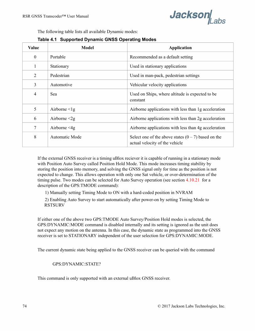
RSR GNSS Transcoder™ User Manual
The following table lists all available Dynamic modes:
Table 4.1 Supported Dynamic GNSS Operating Modes
If the external GNSS receiver is a timing uBlox reciever it is capable of running in a stationary mode with Position Auto Survey called Position Hold Mode. This mode increases timing stability by storing the position into memory, and solving the GNSS signal only for time as the position is not expected to change. This allows operation with only one Sat vehicle, or over-determination of the timing pulse. Two modes can be selected for Auto Survey operation (see section 4.10.21 for a description of the GPS:TMODE command):
1) Manually setting Timing Mode to ON with a hard-coded position in NVRAM2) Enabling Auto Survey to start automatically after power-on by setting Timing Mode to RSTSURV
If either one of the above two GPS:TMODE Auto Survey/Position Hold modes is selected, the GPS:DYNAMIC:MODE command is disabled internally and its setting is ignored as the unit does not expect any motion on the antenna. In this case, the dynamic state as programmed into the GNSS receiver is set to STATIONARY independent of the user selection for GPS:DYNAMIC:MODE.
The current dynamic state being applied to the GNSS receiver can be queried with the command
GPS:DYNAMIC:STATE?
This command is only supported with an external uBlox GNSS receiver.
Value Model Application
0 Portable Recommended as a default setting
1 Stationary Used in stationary applications
2 Pedestrian Used in man-pack, pedestrian settings
3 Automotive Vehicular velocity applications
4 Sea Used on Ships, where altitude is expected to be constant
5 Airborne <1g Airborne applications with less than 1g acceleration
6 Airborne <2g Airborne applications with less than 2g acceleration
7 Airborne <4g Airborne applications with less than 4g acceleration
8 Automatic Mode Select one of the above states (0 – 7) based on the actual velocity of the vehicle
74 © 2017 Jackson Labs Technologies, Inc.
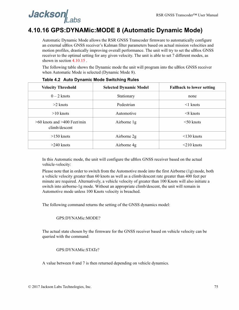
RSR GNSS Transcoder™ User Manual
4.10.16 GPS:DYNAMic:MODE 8 (Automatic Dynamic Mode)Automatic Dynamic Mode allows the RSR GNSS Transcoder firmware to automatically configure an external uBlox GNSS receiver’s Kalman filter parameters based on actual mission velocities and motion profiles, drastically improving overall performance. The unit will try to set the uBlox GNSS receiver to the optimal setting for any given velocity. The unit is able to set 7 different modes, as shown in section 4.10.15 .The following table shows the Dynamic mode the unit will program into the uBlox GNSS receiver when Automatic Mode is selected (Dynamic Mode 8).
Table 4.2 Auto Dynamic Mode Switching Rules
In this Automatic mode, the unit will configure the uBlox GNSS receiver based on the actual vehicle-velocity:Please note that in order to switch from the Automotive mode into the first Airborne (1g) mode, both a vehicle velocity greater than 60 knots as well as a climb/descent rate greater than 400 feet per minute are required. Alternatively, a vehicle velocity of greater than 100 Knots will also initiate a switch into airborne-1g mode. Without an appropriate climb/descent, the unit will remain in Automotive mode unless 100 Knots velocity is breached.
The following command returns the setting of the GNSS dynamics model:
GPS:DYNAMic:MODE?
The actual state chosen by the firmware for the GNSS receiver based on vehicle velocity can be queried with the command:
GPS:DYNAMic:STATe?
A value between 0 and 7 is then returned depending on vehicle dynamics.
Velocity Threshold Selected Dynamic Model Fallback to lower setting
0 – 2 knots Stationary none
>2 knots Pedestrian <1 knots
>10 knots Automotive <8 knots
>60 knots and >400 Feet/min climb/descent
Airborne 1g <50 knots
>150 knots Airborne 2g <130 knots
>240 knots Airborne 4g <210 knots
© 2017 Jackson Labs Technologies, Inc. 75
RSR GNSS Transcoder™ User Manual
The dynamic state is always set to STATIONARY if one of the Position Hold Auto Survey stationary modes is selected using the command GPS:TMODE, as the Position Hold mode setting overrides any dynamic state user setting.Settings will be applied immediately to the uBlox GNSS receiver, and are stored in Non Volatile memory. This command is only supported with an external uBlox GNSS receiver.
4.10.17 GPS:DYNAMic:STATe?This query returns the actual state of the dynamic model, chosen by the firmware to be applied to the external uBlox GNSS receiver depending on vehicle velocity. It returns a value between 0 and 7, which correspond to one of the dynamic models defined in the Table in section 4.10.16 .
This state can be different from the user-selected Dynamic model mode for two reasons:• if the dynamic mode is set to 8 (Automatic mode), the state will reflect the dynamic model being
applied to the GNSS receiver depending on actual vehicle dynamics• if the GPS Timing Mode is set to ON or to RSTSURV, the dynamic state will always be set to 1
(Stationary)This command is only supported with an externa uBlox GNSS receiver.
4.10.18 GPS:REFerence:ADELay <float> <s | ns > [-32767ns,32767ns]The ADELay command allows bi-directional shifting of the 1PPS output in relation to the UTC 1PPS reference in one nanosecond steps. This allows antenna cable delay compensation, as well as retarding or advancing the 1PPS pulse arbitrarily to calibrate different units to each other for example. Typical antenna delays for a 30 foot antenna cable with 1.5ns per foot propagation delay would be compensated with the following command:
GPS:REF:ADEL 45ns
This command can be used to fine-tune different units to have co-incident 1PPS pulse outputs. This command is only supported with an external uBlox GNSS receiver.
4.10.19 GPS:REFerence:PULse:SAWtooth?This command returns the momentary sawtooth correction factor that the GNSS receiver indicated. This command is supported with both an externa uBlox GNSS receiver and a Rockwell Microgram or RSR Puck loaded with custom JLT NMEA firmware.
4.10.20 GPS:RESET ONCEIssues a reset to the internal GNSS receiver. This can be helpful when changing the antenna for example, since the GNSS receiver measures the antenna system’s C/No right after reset, and adjusts its internal antenna amplifier gains accordingly. It takes approximately 1 minute for GPS lock to
76 © 2017 Jackson Labs Technologies, Inc.
RSR GNSS Transcoder™ User Manual
occur after a GNSS receiver reset. The externally-connected GNSS reciever is alternatively re-configured to power-on dfault specifications when issuing this command.
4.10.21 GPS:TMODe <ON | OFF | RSTSURV>This command selects the Timing Mode of an external timing-enabled uBlox GNSS receiver.If the Timing Mode is OFF, the receiver will act as a regular GNSS receiver in 3D mobile mode. This mode has to be chosen if the unit is used with a moving antenna.If the Timing Mode in ON, the timing features of the GNSS receiver are enabled. At power-up, the Hold position stored in NVRAM will be sent to the GNSS receiver and will be used as the reference. In order to use this mode, the receiver position must be known as exactly as possible. Errors in the Hold position will translate into time errors depending on the satellite constellation. The Hold position can be set manually by the user or can be the result of a position Auto Survey executed by the uBlox GNSS receiver.If the Timing Mode is set to RSTSURV, the uBlox GNSS receiver will start an Auto Survey every time the unit is powered-on and following the Survey sequence, the uBlox GNSS receiver will run with the timing features enabled. Once in Position Hold mode, the antenna location should be held completely stationary. This command is only supported with an external Timing uBlox GNSS receiver.
4.10.22 GPS:SURVey ONCEThis command starts an Auto Survey. At the end of the Survey, the calculated Hold position will be stored in NVRAM. The Survey parameters can be set with the command GPS:SURVey:DURation and GPS:SURVey:VARiance. This command is only supported with an external Timing uBlox GNSS receiver.
4.10.23 GPS:SURVey:DURation <sec>This command sets the Survey minimal duration. It is only supported with an external Timing uBlox GNSS receiver.
4.10.24 GPS:SURVey:VARiance <mm2>This command specifies the minimum variance of the average position computed during the Survey. This minimum value is used as a threshold under which the uBlox GNSS receiver can stop the Survey. The GNSS receiver will stop the Survey when the minimal duration has been reached and the variance of the average position is under the specified minimum variance. This command is only supported with an external Timing uBlox GNSS receiver.
4.10.25 GPS:HOLD:POSition <cm, cm, cm>This command allows the user to manually specify the exact position of the antenna. This command will overwrite the Hold position in NVRAM. A subsequent Auto Survey will overwrite this Hold
© 2017 Jackson Labs Technologies, Inc. 77
RSR GNSS Transcoder™ User Manual
position. The Hold position is stored in ECEF coordinates. This command is only supported with an external Timing uBlox GNSS receiver.
4.10.26 GPS:SURVey:STATus?This query displays the current status of the Auto Survey. The status of the survey is in one of the 3 states: ACTIVE : a survey is in progress VALID: a survey has been achieved successfully and the uBlox GNSS receiver is now using this Hold position as reference. INVALID: no survey is in progress or has been achieved since the last power cycle.When in ACTIVE or VALID state, this query will also display the duration, the Hold position in ECEF coordinates and the position variance. This command is only supported with an external Timing uBlox GNSS receiver.
4.10.27 GPS:INITial:DATE <yyyy,mm,dd>This command allows the manual setting of the internal RTC DATE when operating the unit in GNSS-denied environments. This command is compatible to the PTIME:OUT ON command described in section 4.11 to allow automatic time and date synchronization of two units to each other. This command can also be used to set the date for simulations when using the Continuous Simulation Time mode.
4.10.28 GPS:INITial:TIME <hour,min,sec>This command allows manual setting of the internal RTC TIME when operating the unit in GNSS-denied environments. This command is compatible to the PTIME:OUT ON command described in section 4.11 to allow automatic time and date synchronization of two units to each other. This command can also be used to set the time for simulations when using the Continuous Simulation Time mode.
4.10.29 GPS:SYST:SELect [GPS | SBAS | QZSS | GAL | BD | GLO]This command selects the GNSS systems that are enabled in an externally connected uBlox-8 GNSS receiver. The command is followed by any combination of the currently supported GNSS system abbreviations GPS, SBAS, QZSS, BD (BeiDou), GAL (Galileo) and GLO (GLONASS). Up to three concurrent GNSS systems plus SBAS may be enabled at any time. This command is only supported with an external uBlox generation 8 or later GNSS receiver. Only two different L1 carrier frequencies are allowed to be received at any given time, and GPS, Galileo, QZSS, and SBAS count as one frequency, while BeiDou and Glonass each count as a separate frequency. So while GPS, Galileo, and Glonass can be received concurrently, Only BeiDou and Glonass, or Galileo and BeiDou etc can be received concurrently for example. Any illegal GNSS system combinations will result in a “command error” response from the system. A typical example of this command is:
GPS:SYST:SEL GPS SBAS GAL GLO
78 © 2017 Jackson Labs Technologies, Inc.
RSR GNSS Transcoder™ User Manual
4.10.30 GPS:JAMlevel?Externally-connected uBlox GNSS receivers will detect, and flag jamming interference with levels ranging from 0 (no jamming) to 255 (strong jamming) and indicate the jamming level with this command. This command is only supported with an external uBlox GNSS receiver.
4.10.31 GPS:FWver?This command returns the firmware version used inside the externally-connected GNSS receiver itself. This command is supported with both an external uBlox GNSS receiver and a Rockwell Microgram or RSR Puck.
4.10.32 GPS:DAGR:MODEThis command sets the DAGR pass-through mode. An external DAGR DB-15 serial and 1PPS interface may be connected to the externally connected MicroGRAM or RSR Puck SAASM receiver COM-2 port as long as these have the custom JLT NMEA timing firmware loaded by the Rockwell Collins factory. When DAGR pass-through mode is ON,external DAGR PVT data including the 1PPS reference is passed through the internal MicroGRAM receiver COM-2 port and provided in place of locally computed PVT data from the internal MicroGRAM. The GPS:DAGR:PVTstate? query response described in Section 4.10.35 indicates if the MicroGRAM has successfully transitioned to DAGR pass-through PVT mode.When DAGR pass-through mode is ON, the internal MicroGRAM can also accept Hot-Start data from the external DAGR allowing downloading Almanac and Ephemeris as well as PVT data to the MicroGRAM. Once the MicroGRAM has successfully transitioned to DAGR PVT mode, the hot start is typically initiated from the external DAGR. The GPS:DAGR:XFERstate query response described in Section 4.10.34 indicates the success or failure of an attempted hot start.The format of this command is:
GPS:DAGR:MODE <ON | OFF>This command only works with an external MicroGRAM or RSR Puck.
4.10.33 GPS:DAGR:MODE?This query displays the current DAGR pass-through mode. This command does not indicate the success or failure of entering the DAGR pass-through mode, but only the currently selected mode from the GPS:DAGR:MODE command. Use the GPS:DAGR:PVTstate? query to determine the success or failure of entering DAGR pass-through mode.This command only works with an external Rockwell Collins MicroGRAM or RSR Puck with custom JLT Timing firmware loaded at the factory.
© 2017 Jackson Labs Technologies, Inc. 79
RSR GNSS Transcoder™ User Manual
4.10.34 GPS:DAGR:XFERstate?This query displays the DAGR / Hot-Start Transfer Status using the values in the following table:
This command only works with an external Rockwell Collins MicroGRAM or RSR Puck.
4.10.35 GPS:DAGR:PVTstate?This query displays the DAGR pass-through status using the values in the following table:
This command only works with an external Rockwell Collins MicroGRAM or RSR Puck.
4.10.36 GPS:SASTAT:YTRACK?This query displays the number of satellites being tracked in Y-Code. If the MicroGRAM or RSR Puck is not keyed, this value should always be 0. The maximum value is 12. This command only works with an external Rockwell Collins MicroGRAM or RSR Puck.
4.10.37 GPS:SASTAT:CVZStatus?This query displays the CV Zeroize Status using the values in the following table:
This command only works with an external Rockwell Collins MicroGRAM or RSR Puck.
Value Status
0 None, no transfer initiated
1 In Progress
2 Done
3 Error
Value Status
0 None, DAGR pass-through mode off
1 Initializing
2 Done
3 Error
Value Status
0 Verified
1 Failed
2 None, not attempted
80 © 2017 Jackson Labs Technologies, Inc.
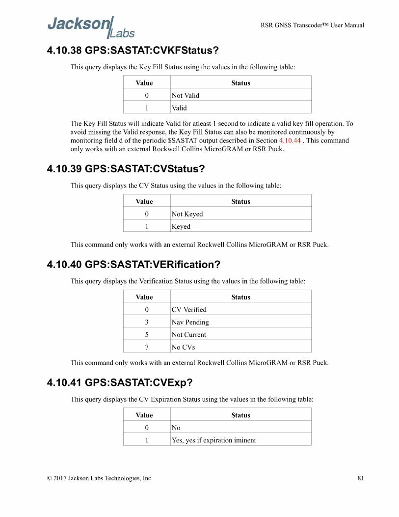
RSR GNSS Transcoder™ User Manual
4.10.38 GPS:SASTAT:CVKFStatus?This query displays the Key Fill Status using the values in the following table:
The Key Fill Status will indicate Valid for atleast 1 second to indicate a valid key fill operation. To avoid missing the Valid response, the Key Fill Status can also be monitored continuously by monitoring field d of the periodic $SASTAT output described in Section 4.10.44 . This command only works with an external Rockwell Collins MicroGRAM or RSR Puck.
4.10.39 GPS:SASTAT:CVStatus?This query displays the CV Status using the values in the following table:
This command only works with an external Rockwell Collins MicroGRAM or RSR Puck.
4.10.40 GPS:SASTAT:VERification?This query displays the Verification Status using the values in the following table:
This command only works with an external Rockwell Collins MicroGRAM or RSR Puck.
4.10.41 GPS:SASTAT:CVExp?This query displays the CV Expiration Status using the values in the following table:
Value Status
0 Not Valid
1 Valid
Value Status
0 Not Keyed
1 Keyed
Value Status
0 CV Verified
3 Nav Pending
5 Not Current
7 No CVs
Value Status
0 No
1 Yes, yes if expiration iminent
© 2017 Jackson Labs Technologies, Inc. 81
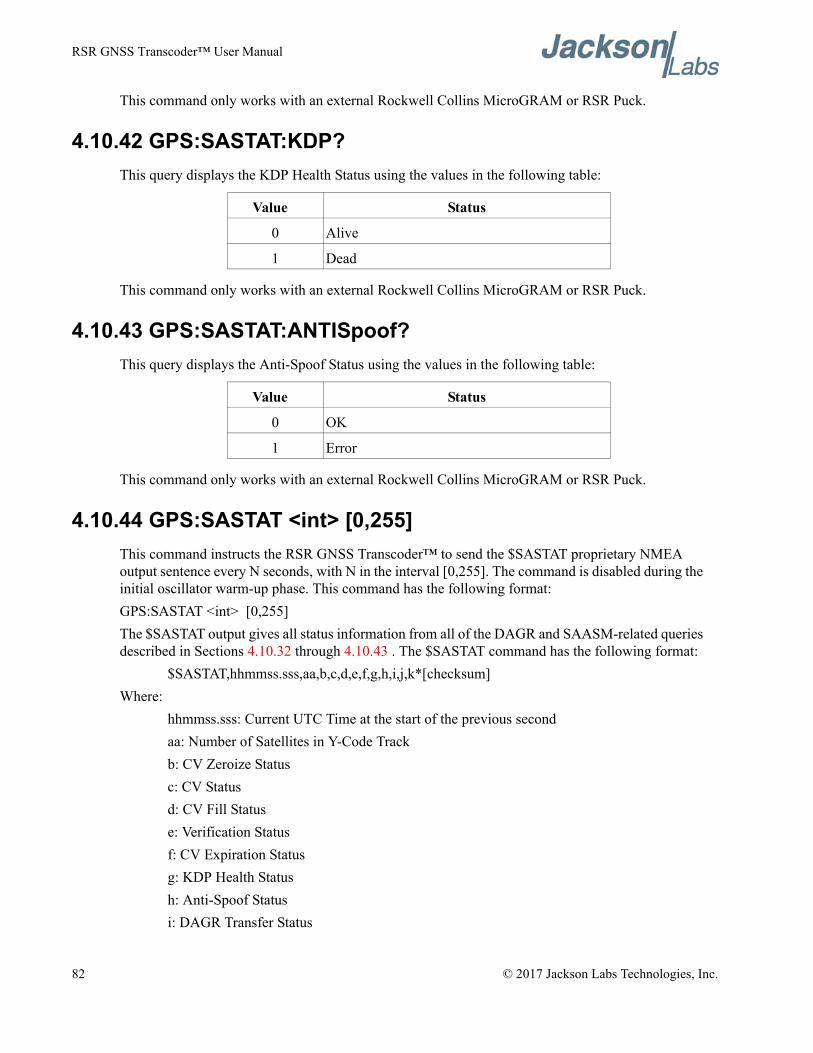
RSR GNSS Transcoder™ User Manual
This command only works with an external Rockwell Collins MicroGRAM or RSR Puck.
4.10.42 GPS:SASTAT:KDP?This query displays the KDP Health Status using the values in the following table:
This command only works with an external Rockwell Collins MicroGRAM or RSR Puck.
4.10.43 GPS:SASTAT:ANTISpoof?This query displays the Anti-Spoof Status using the values in the following table:
This command only works with an external Rockwell Collins MicroGRAM or RSR Puck.
4.10.44 GPS:SASTAT <int> [0,255]This command instructs the RSR GNSS Transcoder™ to send the $SASTAT proprietary NMEA output sentence every N seconds, with N in the interval [0,255]. The command is disabled during the initial oscillator warm-up phase. This command has the following format:GPS:SASTAT <int> [0,255]The $SASTAT output gives all status information from all of the DAGR and SAASM-related queries described in Sections 4.10.32 through 4.10.43 . The $SASTAT command has the following format:
$SASTAT,hhmmss.sss,aa,b,c,d,e,f,g,h,i,j,k*[checksum]Where:
hhmmss.sss: Current UTC Time at the start of the previous secondaa: Number of Satellites in Y-Code Trackb: CV Zeroize Statusc: CV Statusd: CV Fill Statuse: Verification Statusf: CV Expiration Statusg: KDP Health Statush: Anti-Spoof Statusi: DAGR Transfer Status
Value Status
0 Alive
1 Dead
Value Status
0 OK
1 Error
82 © 2017 Jackson Labs Technologies, Inc.
RSR GNSS Transcoder™ User Manual
j: DAGR PVT Statek: DAGR PVT Mode
The [checksum] follows the NMEA standard checksum. This command only works with an external Rockwell Collins MicroGRAM or RSR Puck.
4.10.45 GPS:ZEROize STARTThis command starts the CV Zeroize operation on the MicroGRAM or RSR Puck receiver. The START parameter must be included, otherwise the command is not accepted. The format of this command is:
GPS:ZEROize STARTThe response from the GPS:SASTAT:CVZStatus? query provides the result of the CV Zeroize operation. This command only works with an external Rockwell Collins MicroGRAM or RSR Puck.
4.10.46 GPS:ZEROize?This query displays the CV Zeroize Status and is equivalent to the GPS:SASTAT:CVZStatus? query described in Section 4.10.37 . This command only works with an external Rockwell Collins MicroGRAM or RSR Puck.
4.10.47 GPS?This query displays the configuration, position, speed, height and other relevant data of the external GNSS receiver in one convenient location.
4.11 INTGPS SubsystemThe INTGPS subsystem groups all the commands related to the control and status of the internal monitoring GNSS receiver. The internal GNSS receiver is used to monitor the RF output signal on the SMA connector, providing a sanity check for the simulated position and calibrating the timing for the simulated signal. The list of the commands supported is the following:
INTGPS:SATellite:TRAcking:COUNt?INTGPS:SATellite:VISible:COUNt?INTGPS:GPGGA <int> [0,255]INTGPS:GPRMC <int> [0,255]INTGPS:GPGSV<int> [0,255]INTGPS:GPZDA<int> [0,255]INTGPS:PASHR<int> [0,255]INTGPS:XYZSPeedINTGPS:HEIGHT?INTGPS:HEIGHT:MSL?INTGPS:HEIGHT:GPS?
© 2017 Jackson Labs Technologies, Inc. 83
RSR GNSS Transcoder™ User Manual
INTGPS:DYNAMic <int> [0,7]INTGPS:DYNAMic 8 (Automatic Dynamic Mode)INTGPS:DYNAMic?INTGPS:REFerence:PULse:SAWtooth?INTGPS:RESET ONCEINTGPS:JAMlevel?INTGPS:FWver?INTGPS?
4.11.1 INTGPS:SATelliteThis group of commands describe the satellite constellation as seen by the internal GNSS receiver.
4.11.2 INTGPS:SATellite:TRAcking:COUNt?This query returns the number of satellites being tracked by the internal GNSS receiver.
4.11.3 INTGPS:SATellite:VISible:COUNt?This query returns the number of satellites that the almanac predicts should be visible, given date, time, and position.
4.11.4 Internal GNSS Receiver NMEA SupportThe following commands allow the RSR GNSS Transcoder™ to provide standard NMEA data from the internal GNSS receiver. The GPGGA,GPRMC, GPGSV, PASHR and GPZDA NMEA commands comprise all necessary information about the antenna position, height, velocity, direction, satellite info, fix info, time, date and other information that can be used by standard navigation applications or as a comparison with the simulation results from the target GPS receiver.Once enabled, the RSR GNSS Transcoder™ will send out information on the USB serial interface automatically every N seconds. All incoming serial commands are still recognized by RSR GNSS Transcoder™ since the serial interface transmit and receive lines are completely independent of one another. Please note that the NMEA output configured for the internal GNSS receiver appears identical to the NMEA output for the optional external GNSS receiver. To prevent confusing the output, only one (internal or external) NMEA sentence of each type should be enabled.Please also note that the position, direction, and speed data is delayed by one second from when the GPS receiver internally reported these to the RSR GNSS Transcoder™’s Microprocessor, so the position is valid for the 1PPS pulse previous to the last 1PPS pulse at the time the data is sent (one second delay). The time and date are properly output with correct UTC synchronization to the 1PPS pulse immediately prior to the data being sent.Once set, the following two commands will be stored in NV memory, and generate output information even after power to the unit has been cycled.
84 © 2017 Jackson Labs Technologies, Inc.
RSR GNSS Transcoder™ User Manual
4.11.5 INTGPS:GPGGAThis command instructs the RSR GNSS Transcoder™ to send the NMEA standard string $GPGGA every N seconds, with N in the interval [0,255]. The command is disabled until the internal GNSS receiver achieves a first fix.This command has the following format:
INTGPS:GPGGA <int> [0,255]GPGGA shows height in MSL Meters, this is different from traditional GPS receivers that display height in GPS Meters. The difference between MSL and GPS height can be significant, 35m or more are common. Please note that the simulation height is specified in GPS height above elipsoid, so the height returned by this NMEA message will vary from the simulated height by the GPS to MSL height difference at the particular location that is being simulated.
4.11.6 INTGPS:GPRMCThis command instructs the RSR GNSS Transcoder™ to send the NMEA standard string $GPRMC every N seconds, with N in the interval [0,255]. The command is disabled until the internal GNSS receiver achieves a first fix.This command has the following format:
INTGPS:GPRMC <int> [0,255]
4.11.7 INTGPS:GPGSVThis command instructs the RSR GNSS Transcoder™ to send the NMEA standard string $GPGSV every N seconds,with N in the interval [0,255]. The command is disabled until the internal GPS receiver achieves a first fix.
INTGPS:GPGSV <int> [0,255]
4.11.8 INTGPS:XYZSPeed This command is a 3D velocity vector output command. Enabling this command will output a 3 dimensional velocity vector indicating the unit’s speed in centimeters per second in the ECEF coordinate system.X, Y, and Z speed are individually given, and are independent of each other. An accuracy estimate in centimeters per second is also given. The velocity data is time-stamped using the time-of-week with a resolution of milliseconds.Additionally, the number of accrued Leapseconds is indicated in this message, which allows proper calculation of GPS time from UTC time as indicated by other messages, as well as proper handling of Leapsecond events.Use the following format to generate the velocity vector every N seconds, with N in the interval [0,255]:
INTGPS:XYZSPeed <int> [0,255]
© 2017 Jackson Labs Technologies, Inc. 85
RSR GNSS Transcoder™ User Manual
4.11.9 INTGPS:GPZDAThis command instructs the RSR GNSS Transcoder™ to send the NMEA standard string $GPZDA every N seconds, with N in the interval [0,255]. The command is disabled until the internal GNSS receiver achieves a first fix.This command has the following format:
INTGPS:GPZDA <int> [0,255]
4.11.10 INTGPS:PASHRThe NMEA string $PASHR,POS has been added for compatibility to legacy GPS hardware. The PASHR command alongside the GPZDA command will give all relevant parameters such as time, date, position, velocity, direction, altitude, quality of fix, and more. As an example, the String has the following data format:$PASHR,POS,0,7,202939.00,3716.28369,N,12157.43457,W,00087.40,????,070.01,000.31,-000.10,05.6,03.5,04.3,00.0,DD00*32Please note that the length of the string is fixed at 115 characters plus the two binary 0x0d, 0x0a termination characters.$PASHR,POS,0,aa,bbbbbb.00,cccc.ccccc,d,eeeee.eeeee,f,ggggg.gg,hhhh,iii.ii,jjj.jj,kkkk.kk,ll.l,mm.m,nn.n,00.0,p.pp,*[checksum]
Where:
aa:Number of Satsbbbbbb.00:Time of Day UTCcccc.ccccc,d:Latitude,S/Neeee.eeeee,f:Longitude,W/Eggggg.gg:Antenna Height in metershhhh:Four fixed ‘?’ symbolsiii.ii:Course Over Groundjjj.jj:Speed in Knotskkkk.k:Vertical Velocity in meters/sll.l:PDOPmm.mHDOPnn.nVDOP00.0Static numberp.pp:Firmware Version (1.05 and above)
86 © 2017 Jackson Labs Technologies, Inc.
RSR GNSS Transcoder™ User Manual
This command instructs the RSR GNSS Transcoder™ to send the NMEA standard string $PASHR every N seconds, with N in the interval [0,255]. The command is disabled until the internal GNSS receiver achieves a first fix.This command has the following format:
INTGPS:PASHR <int> [0,255]
4.11.11 INTGPS:HEIGHT:MSL?This query returns the Mean Sea Level height in meters which differs from the GPS ellipsoid height by up to +/-100 meters. This difference varies depending upon the location as reported by the internal GPS receiver. Please note that the simulation uses GPS height in commands such as the SIM:POS:LLH command described in Section 4.3.9
4.11.12 INTGPS:HEIGHT:GPS?This query returns the GPS ellipsoid height in meters as reported by the internal GPS reference receiver. It is calculated from the internal uBlox GNSS receivers’ MSL height parameter by subtracting the MSL to GPS elipsoid height difference for the simulated position. This GPS height should reflect the simulated height as set in the simulation commands such as the SIM:POS:LLH command described in Section 4.3.9 .
4.11.13 INTGPS:HEIGHT?This command returns the output from the following queries:
INTGPS:HEIGHT:MSL?INTGPS:HEIGHT:GPS?
4.11.14 INTGPS:DYNAMic:MODEThis command allows the user to select the dynamic motion model being applied to the Kalmann filters in the internal monitoring GNSS receiver. This allows for larger amounts of filtering for lower velocity applications, effectively reducing noise and multipath interference. Applications with high acceleration can now be used with fast filter settings to allow for the most accurate GPS coordinates to be provided in high-dynamic applications such as Jet aircraft. Doppler tracking is enabled in all airborne modes, as Carrier Phase tracking is very difficult to achieve in high velocity applications. The GNSS receiver will perform Carrier Phase tracking for non-airborne modes.The command has the following syntax:
INTGPS:DYNAMic:MODE <int> [0,8]
Sending the following command to the RSR GNSS Transcoder™ will select a stationary GNSS dynamic model for example:
INTGPS:DYNAM:MODE 1
© 2017 Jackson Labs Technologies, Inc. 87
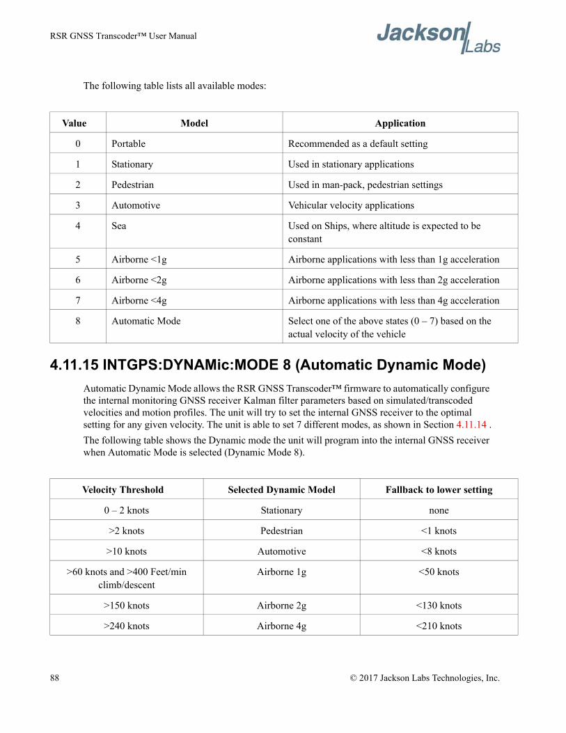
RSR GNSS Transcoder™ User Manual
The following table lists all available modes:
4.11.15 INTGPS:DYNAMic:MODE 8 (Automatic Dynamic Mode)Automatic Dynamic Mode allows the RSR GNSS Transcoder™ firmware to automatically configure the internal monitoring GNSS receiver Kalman filter parameters based on simulated/transcoded velocities and motion profiles. The unit will try to set the internal GNSS receiver to the optimal setting for any given velocity. The unit is able to set 7 different modes, as shown in Section 4.11.14 .The following table shows the Dynamic mode the unit will program into the internal GNSS receiver when Automatic Mode is selected (Dynamic Mode 8).
Value Model Application
0 Portable Recommended as a default setting
1 Stationary Used in stationary applications
2 Pedestrian Used in man-pack, pedestrian settings
3 Automotive Vehicular velocity applications
4 Sea Used on Ships, where altitude is expected to be constant
5 Airborne <1g Airborne applications with less than 1g acceleration
6 Airborne <2g Airborne applications with less than 2g acceleration
7 Airborne <4g Airborne applications with less than 4g acceleration
8 Automatic Mode Select one of the above states (0 – 7) based on the actual velocity of the vehicle
Velocity Threshold Selected Dynamic Model Fallback to lower setting
0 – 2 knots Stationary none
>2 knots Pedestrian <1 knots
>10 knots Automotive <8 knots
>60 knots and >400 Feet/min climb/descent
Airborne 1g <50 knots
>150 knots Airborne 2g <130 knots
>240 knots Airborne 4g <210 knots
88 © 2017 Jackson Labs Technologies, Inc.
RSR GNSS Transcoder™ User Manual
In this Automatic mode, the unit will configure the internal GNSS receiver based on the simulated/transcoded vehicle-velocity:Please note that in order to switch from the Automotive mode into the first Airborne (1g) mode, both a vehicle velocity greater than 60 knots as well as a climb/descent rate greater than 400 feet per minute are required. Alternatively, a vehicle velocity of greater than 100 Knots will also initiate a switch into airborne-1g mode. Without an appropriate climb/descent, the unit will remain in Automotive mode.
The following command returns the setting of the GNSS dynamic model:
INTGPS:DYNAMic:MODE?
The actual state chosen by the firmware for the internal GNSS receiver based on vehicle velocity can be obtained with the command:
INTGPS:DYNAMic:STATe?
A value between 0 and 7 is then returned depending on simulated/transcoded vehicle dynamics.Settings will be applied immediately to the internal GNSS receiver, and are stored in Non Volatile memory.
4.11.16 INTGPS:DYNAMic:STATe?This query returns the actual state of the dynamic model, chosen by the firmware to be applied to the internal GNSS receiver depending on simulated/transcoded vehicle velocity. It returns a value between 0 and 7, which correspond to one of the dynamic models defined in the Table in section 4.10.16 .This state can be different from the user-selected Dynamic model mode if the dynamic mode is set to 8 (Automatic mode), the state will reflect the dynamic model being applied to the internal GNSS receiver depending on simulated/transcoded vehicle dynamics
4.11.17 INTGPS:REFerence:PULse:SAWtooth?This command returns the momentary sawtooth correction factor that the internal monitoring GNSS receiver indicated.
4.11.18 INTGPS:RESET ONCEIssues a reset to the internal GNSS receiver. This can be helpful when changing amplitude settings on the simulation, since the internal GNSS receiver measures the RF outputs’s C/No right after reset, and adjusts its internal antenna amplifier gains accordingly. It takes approximately 1 minute for locking to commence after a GNSS receiver reset, as indicated by the internal GNSS 1PPS LED.
© 2017 Jackson Labs Technologies, Inc. 89
RSR GNSS Transcoder™ User Manual
4.11.19 INTGPS:JAMlevel?This command provides a signal jamming-indicator from the internal monitoring GNSS receiver. The internal GNSS receiver will detect, and flag jamming interference with levels ranging from 0 (no jamming) to 255 (strong jamming). Normally the jamming level is low on a correctly operating RSR GNSS Transcoder™.
4.11.20 INTGPS:FWver?This command queries and returns the Firmware version used inside the internal monitoring uBlox GNSS receiver.
4.11.21 INTGPS?This query displays the configuration, position, speed, height and other relevant data of the internal monitoring GNSS receiver in one convenient location.
4.12 PTIME SubsystemThe PTIME subsystem groups all the commands related to the management of the internal RTC time including simulation time when running in the Continuous simulation time mode. Please note that the RSR GNSS Transcoder™ does not contain a battery-backup to maintain RTC time/date, thus the time/date is lost when power is removed, or when the unit is reset.The list of the commands supported is the following:
PTIMe:DATE?PTIMe:TIME?PTIMe:TIME:STRing?PTIMe:TINTerval?PTIME:OUTput <on|off>PTIMe:LEAPsecond?PTIMe:LEAPsecond:PENDing?PTIMe:LEAPsecond:ACCumulated?PTIMe:LEAPsecond:DATE?PTIMe:LEAPsecond:DURation?PTIME?
4.12.1 PTIMe:DATE?This query returns the current calendar date. The local calendar date is referenced to UTC time. The year, month, and day are returned.
90 © 2017 Jackson Labs Technologies, Inc.
RSR GNSS Transcoder™ User Manual
4.12.2 PTIMe:TIME?This query returns the current 24-hour time. The local time is referenced to UTC time. The hour, minute, and second is returned.
4.12.3 PTIMe:TIME:STRing?This query returns the current 24-hour time suitable for display (for example, 13:24:56).
4.12.4 PTIME:OUTput <ON | OFF>This command allows connecting two units together through the USB serial port, and having the master unit send time and date information to the slave unit. This allows time-synchronization between two units which can be useful when operating in GPS/GNSS denied environments.Sending the command PTIM:OUT ON will cause the unit to automatically generate GPS:INIT:DATE and GPS:INIT:TIME sentences on the USB serial port once per second.
4.12.5 PTIMe:LEAPsecond?This command returns the results of the four following queries:PTIMe:LEAPsecond:PENDing?PTIMe:LEAPsecond:ACCumulated?PTIMe:LEAPsecond:DATE?PTIMe:LEAPsecond:DURation?
4.12.6 PTIMe:LEAPsecond:PENDing?This command returns 1 if the GPS Almanac data contains a future pending leap second data and 0 if no future leap second is pending or Almanac data is not available. The GNSS receiver must have the GPS system enabled for the GPS Almanac to be available.
4.12.7 PTIMe:LEAPsecond:ACCumulated?This command returns the internally applied leapsecond offset between GPS time and UTC time as stored in the EEPROM (GPS Almanac not received yet) or as indicated by the GNSS receiver (GPS Almanac is available).
4.12.8 PTIMe:LEAPsecond:DATE?This command returns the date of the pending leap second, if any.
© 2017 Jackson Labs Technologies, Inc. 91
RSR GNSS Transcoder™ User Manual
4.12.9 PTIMe:LEAPsecond:DURation?This command returns the duration of the last minute of the day during a leap second event. The returned value is 59, 60 or 61 if GPS Almanac data is available, and 0 otherwise. A response of 60 indicates that no leap second is pending.
4.12.10 PTIME?This query returns the result of the following queries:
PTIME:DATE?PTIME:TIME?PTIME:TINTerval?PTIME:OUTput?PTIME:LEAPsecond:ACCumulated?
4.13 SYSTEM SubsystemThis subsystem groups the commands related to the general configuration of the RSR GNSS Transcoder™. The list of the commands supported for this subsystem follows:
SYSTem:COMMunicate:SERial:ECHO <ON | OFF> SYSTem:COMMunicate:SERial:PROmpt <ON | OFF>SYSTem:COMMunicate:SERial:BAUD <9600 | 19200 | 38400 | 57600 | 115200>SYSTem:FACToryreset ONCESYSTem:ID:SN?SYSTem:ID:HWrev?SYSTem:STATus?
4.13.1 SYSTem:COMMunicate:SERial:ECHOThis command enables/disables echo on the serial port. Echo should be turned off when using the Z38xx application program. This command has the following format:
SYSTem:COMMunicate:SERial:ECHO <ON | OFF>
4.13.2 SYSTem:COMMunicate:SERial:PROmpt This command enables/disables the prompt “scpi>” on the SCPI command lines. The prompt must be enabled when used with the software GPSCon. This command has the following format:
SYSTem:COMMunicate: SERial:PROmpt <ON | OFF>
92 © 2017 Jackson Labs Technologies, Inc.
RSR GNSS Transcoder™ User Manual
4.13.3 SYSTem:COMMunicate:SERial:BAUD This command sets the USB serial speed. The serial configuration is always 8 bit, 1 stop bit, no parity, no flow control. Upon Factory reset, the speed is set at 115,200 baud. This command has the following format:
SYSTem:COMMunicate:SERial:BAUD <9600 | 19200 | 38400 | 57600 | 115200>
4.13.4 SYSTem:FACToryreset ONCEThis command applies the Factory Reset setting to the NVRAM. User parameters and calibration parameters are overwritten with factory default values.
4.13.5 SYSTem:ID:SN?This query returns the serial number of the unit.
4.13.6 SYSTem:ID:HWrev?This query returns the Hardware version of the module.
4.13.7 SYSTem:STATus?This query returns a full page of external GNSS receiver status in ASCII format. The output is compatible with GPSCon. This command returns one of the most comprehensive external GNSS and oscillator status pages.
4.14 SERVO SubsystemThis subsystem groups all the commands related to the adjustment of the servo loop:
SERVo:LOOP?SERVo:COARSeDac <int> [0,225]SERVo:DACGain <int> [0.1,10000]SERVo:EFCScale <float>[0.0 , 500.0]SERVo:EFCDamping <float>[0.0 , 4000.0]SERVo:SLOPe <NEG | POS >SERVo:TEMPCOmpensation <float> [-4000.0, 4000.0]SERVo:AGINGcompensation <float> [-10.0, 10.0]SERVo:PHASECOrrection <float> [-100.0, 100.0]SERVo:1PPSoffset <int> nsSERVo:QUIet <ON | OFF>SERVo:TRACe <int > [0,255]SERVo?
© 2017 Jackson Labs Technologies, Inc. 93
RSR GNSS Transcoder™ User Manual
4.14.1 SERVo:LOOP?This command returns the currently enabled servo loop and responds with either TCXO or CSAC. This command is supported only on the RSR GNSS Transcoder™ with the internal CSAC option.
4.14.2 SERVo:COARSeDacThis command sets the coarse DAC that controls the TCXO EFC on units without CSAC option. The RSR GNSS Transcoder™ control loop automatically adjusts this setting during disciplining. The user should not have to change this value.This command has the following format:
SERVo:COARSeDac <int> [0,225]
4.14.3 SERVo:DACGainThis command is used for factory setup.
4.14.4 SERVo:EFCScaleControls the Proportional part of the PID loop. Typical values are 0.5 to 3.0. Larger values increase the loop control at the expense of increased noise while locked. Setting this value too high can cause loop instabilities.This command has the following format:
SERVo: EFCScale <float>[0.0 , 500.0]
4.14.5 SERVo:EFCDampingSet’s the Low Pass filter effectiveness of the DAC. Values from 2.0 to 50 are typically used. Larger values result in less noise at the expense of phase delay.This command has the following format:
SERVo:EFCDamping <float>[0.0 , 4000.0]
4.14.6 SERVo:SLOPeThe parameter determines the sign of the slope between the EFC and the frequency variation of the TCXO. This parameter should be set to match the TCXO’s EFC frequency slope and should not be changed from factory settings. This command has the following format:
SERVo:SLOPe <NEG | POS >
4.14.7 SERVo:TEMPCOmpensation This command is not supported on the RSR GNSS Transcoder™ board.
94 © 2017 Jackson Labs Technologies, Inc.
RSR GNSS Transcoder™ User Manual
4.14.8 SERVo:AGINGcompensationThis parameter is a coefficient that represents the drift of the EFC needed to compensate the natural drift in frequency of the TCXO or CSAC due to aging. This coefficient is automatically computed and adjusted over time by the Jackson Labs Technologies, Inc. firmware. This command has the following format:
SERVo:AGINGcompensation <float> [-10.0, 10.0]
4.14.9 SERVo:PHASECOrrection This parameter sets the Integral part of the PID loop. Loop instability will result if the parameter is set too high. Typical values are 10.0 to 30.0. This command has the following format:
SERVo:PHASECOrrection <float> [-100.0, 100.0]
4.14.10 SERVo:1PPSoffsetThis command sets the RSR GNSS Transcoder™ 1PPS signal’s offset to UTC in 5.6ns steps.Using the SERV:1PPS command results in immediate phase change of the 1PPS output signal.This command has the following format:
SERVo:1PPSoffset <int> ns
4.14.11 SERVo:TRACeThis command sets the period in seconds for the debug trace output on the USB port. Debug trace data can be used with Ulrich Bangert’s “Plotter” freeware utility to show UTC tracking versus time etc.This command has the following format:
SERVo:TRACe <int > [0,255]An example output is described here:
08-07-31 373815 60685 -32.08 -2.22E-11 14 10 6 0x54[date][1PPS Count][Fine DAC][UTC offset ns][Frequency Error Estimate][Sats Visible][Sats Tracked][Lock State][Health Status]Please see the SYNChronization:health? command for detailed information on how to decode the health status indicator values. The Lock State variable indicates one of the following states:
Value State
0 TCXO/CSAC warmup
1 Holdover
2 Locking (TCXO/CSAC training)
© 2017 Jackson Labs Technologies, Inc. 95
RSR GNSS Transcoder™ User Manual
4.14.12 SERVo?This command returns the result of the following queries:
SERVo:COARSeDac?SERVo:DACGain?SERVo: EFCScale?SERVo:EFCDamping?SERVo:SLOPe?SERVo:TEMPCOmpensation? SERVo:AGINGcompensation? SERVo:PHASECOrrection? SERVo:1PPSoffset? SERVo:TRACe?
4.15 CSAC SubsystemThe following commands are used to query the microcontroller built into the optional CSAC oscillator. These commands are only available on the RSR GNSS Transcoder™ with the optional CSAC oscillator installed.
4.15.1 CSAC:POWerThis command enables/disables the low power mode on the CSAC oscillator. The low power mode is enabled when the power is set to OFF at which point the CSAC will disable all its internal circuitry and the module will operate as a TCXO based unit. The default setting is ON.When the CSAC power is OFF, the internal TCXO is used instead of the CSAC as the timing reference for the system. The SERVo:LOOP? query response also outputs the current timing reference for the system (TCXO or CSAC).The format of this command is:CSAC:POWer <ON | OFF>
4.15.2 CSAC:RS232?This query returns the state (OK or FAIL) of the serial communication between the main CPU and the CSAC internal microcontroller. When the state is FAIL, there is a communication breakdown, and the unit should be power cycled to clear the communication error.
4 [Value not defined]
5 Holdover, but still phase locked (stays in this state for about 100s after GNSS lock is lost)
6 Locked, and external GNSS active
96 © 2017 Jackson Labs Technologies, Inc.
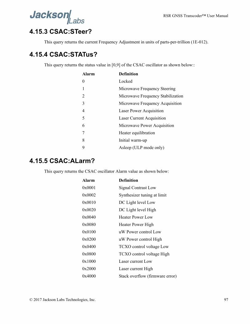
RSR GNSS Transcoder™ User Manual
4.15.3 CSAC:STeer?This query returns the current Frequency Adjustment in units of parts-per-trillion (1E-012).
4.15.4 CSAC:STATus?This query returns the status value in [0,9] of the CSAC oscillator as shown below::
4.15.5 CSAC:ALarm?This query returns the CSAC oscillator Alarm value as shown below:
Alarm Definition0 Locked1 Microwave Frequency Steering2 Microwave Frequency Stabilization3 Microwave Frequency Acquisition4 Laser Power Acquisition5 Laser Current Acquisition6 Microwave Power Acquisition7 Heater equilibration8 Initial warm-up9 Asleep (ULP mode only)
Alarm Definition0x0001 Signal Contrast Low0x0002 Synthesizer tuning at limit0x0010 DC Light level Low0x0020 DC Light level High0x0040 Heater Power Low0x0080 Heater Power High0x0100 uW Power control Low0x0200 uW Power control High0x0400 TCXO control voltage Low0x0800 TCXO control voltage High0x1000 Laser current Low0x2000 Laser current High0x4000 Stack overflow (firmware error)
© 2017 Jackson Labs Technologies, Inc. 97
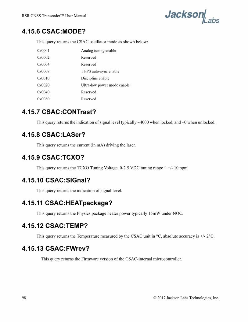
RSR GNSS Transcoder™ User Manual
4.15.6 CSAC:MODE?This query returns the CSAC oscillator mode as shown below:
4.15.7 CSAC:CONTrast?This query returns the indication of signal level typically ~4000 when locked, and ~0 when unlocked.
4.15.8 CSAC:LASer?This query returns the current (in mA) driving the laser.
4.15.9 CSAC:TCXO?This query returns the TCXO Tuning Voltage, 0-2.5 VDC tuning range ~ +/- 10 ppm
4.15.10 CSAC:SIGnal?This query returns the indication of signal level.
4.15.11 CSAC:HEATpackage?This query returns the Physics package heater power typically 15mW under NOC.
4.15.12 CSAC:TEMP?This query returns the Temperature measured by the CSAC unit in °C, absolute accuracy is +/- 2°C.
4.15.13 CSAC:FWrev? This query returns the Firmware version of the CSAC-internal microcontroller.
0x0001 Analog tuning enable
0x0002 Reserved
0x0004 Reserved
0x0008 1 PPS auto-sync enable
0x0010 Discipline enable
0x0020 Ultra-low power mode enable
0x0040 Reserved
0x0080 Reserved
98 © 2017 Jackson Labs Technologies, Inc.
RSR GNSS Transcoder™ User Manual
4.15.14 CSAC:SN?This query returns the Serial Number of the CSAC in the form YYMMCSNNNNN where YYMM is the year and month of production and NNNNN is the serialized unit of that month.
4.15.15 CSAC:LIFEtime?This query returns the accumulated number of hours that the CSAC has been powered on since the last factory reset of the RSR GNSS Transcoder™ board. The value is stored in the external NVRAM and updated every hour when the CSAC is powered on.
4.15.16 CSAC:STeer:LATch ONCEThis command stores the momentary steering offset into the CSAC internal NVRAM. This is done automatically by the firmware once every 24 hours, so as not to damage the CSAC NVRAM which has a limited number of write cycles. The user may force this value to be stored into the CSAC by issuing the CSAC:STeer:LATch ONCE command
4.15.17 CSAC?This query displays all the CSAC queries defined above.
© 2017 Jackson Labs Technologies, Inc. 99
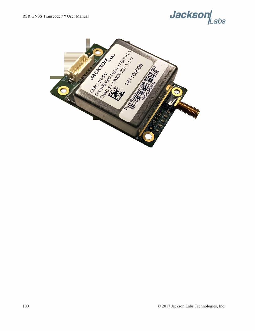
RSR GNSS Transcoder™ User Manual
100 © 2017 Jackson Labs Technologies, Inc.
RSR GNSS Transcoder™ User Manual
Firmware Upgrade Instructions
5.1 IntroductionThe following is a short tutorial on how to upgrade the RSR GNSS Transcoder firmware. Please follow the instructions in order to prevent corrupting the units’ Flash, which may require reflashing at the factory.With some practice, the entire Flash upgrade can be done in less than two minutes, even though the following seems like a fairly long list of instructions.
5.2 ISP Flash Loader Utility InstallationJackson Labs Technologies, Inc. recommends using the Flash Magic utility to upgrade the contents of Flash memory on the RSR GNSS Transcoder. It is available for download on the Flash Magic website:http://www.flashmagictool.com/Follow the directions given on the website for installing the utility on your computer.Note: The Philips LPC2000 utility that is used on other Jackson Labs Technologies, Inc. products will not support the newer LPC18S37 processor used on this product.
5.3 Putting the PCB into In-Circuit Programming (ISP) modeMomentarily short-out pins 1 and 2 of ISP#/RESET# header J3 using a jumper wire or other conductive material (tweezers etc.) during power-on (See Figure 5.1). All LED’s on the PCB should remain off, indicating the unit is properly placed into ISP mode. If the LED’s light up after power-on, the unit is not in ISP mode. If the unit is in the optional IP67 enclosure, then the ISP# pin is accessible through the DB-15 connector, Pin 6.
© 2017 Jackson Labs Technologies, Inc. 101
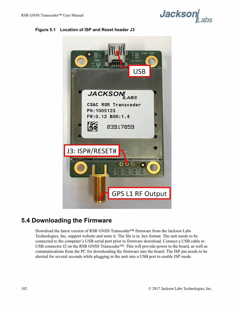
RSR GNSS Transcoder™ User Manual
Figure 5.1 Location of ISP and Reset header J3
5.4 Downloading the FirmwareDownload the latest version of RSR GNSS Transcoder™ firmware from the Jackson Labs Technologies, Inc. support website and store it. The file is in .hex format. The unit needs to be connected to the computer’s USB serial port prior to firmware download. Connect a USB cable to USB connector J2 on the RSR GNSS Transcoder™. This will provide power to the board, as well as communications from the PC for downloading the firmware into the board. The ISP pin needs to be shorted for several seconds while plugging in the unit into a USB port to enable ISP mode.
Shortout pins 1 and 2 of J2prior to power-on toenter ISP mode
102 © 2017 Jackson Labs Technologies, Inc.
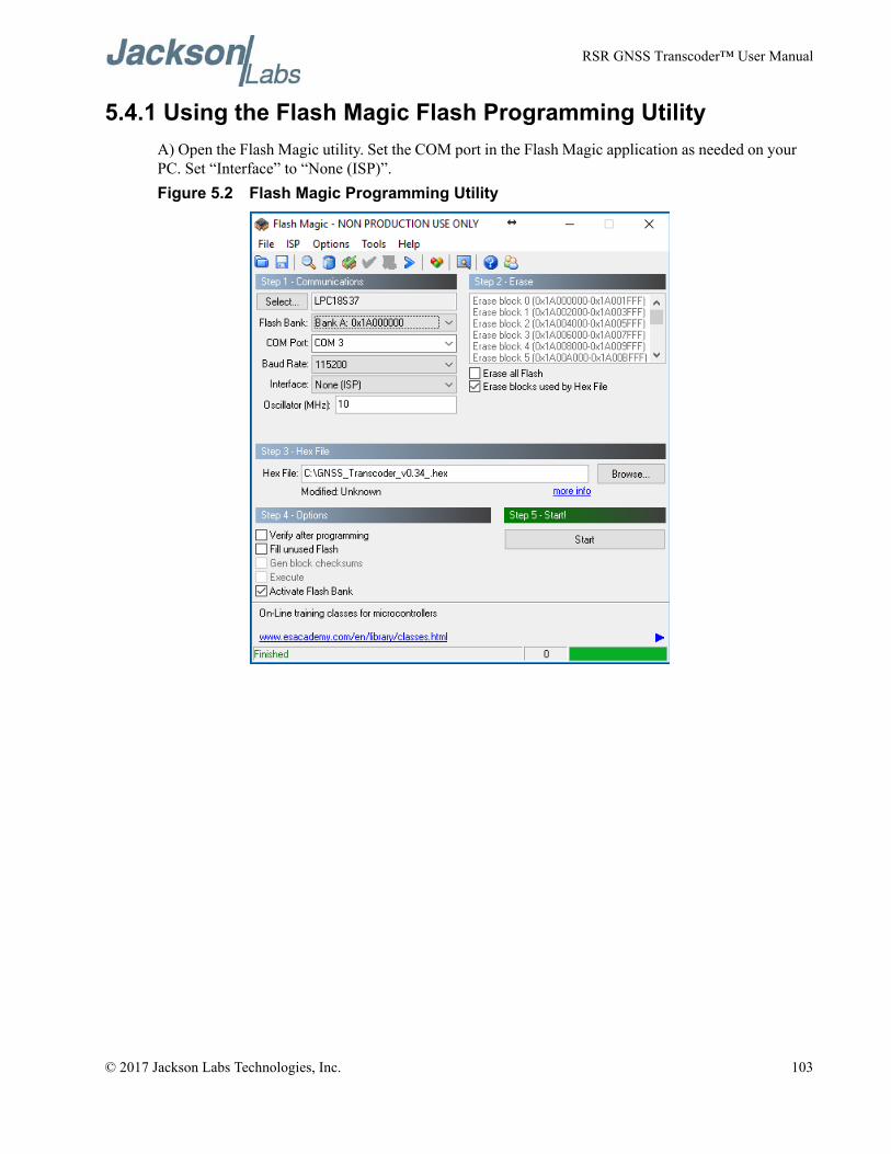
RSR GNSS Transcoder™ User Manual
5.4.1 Using the Flash Magic Flash Programming UtilityA) Open the Flash Magic utility. Set the COM port in the Flash Magic application as needed on your PC. Set “Interface” to “None (ISP)”.Figure 5.2 Flash Magic Programming Utility
© 2017 Jackson Labs Technologies, Inc. 103
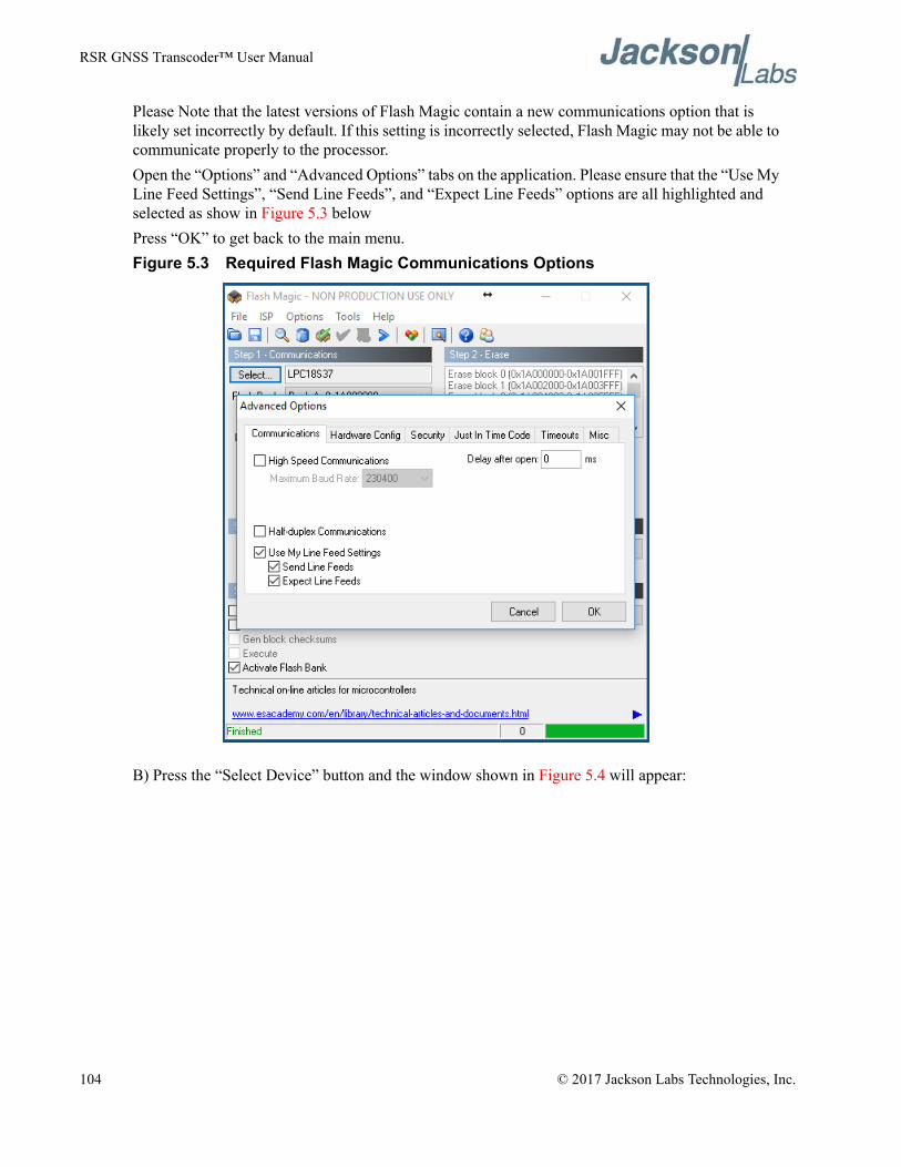
RSR GNSS Transcoder™ User Manual
Please Note that the latest versions of Flash Magic contain a new communications option that is likely set incorrectly by default. If this setting is incorrectly selected, Flash Magic may not be able to communicate properly to the processor. Open the “Options” and “Advanced Options” tabs on the application. Please ensure that the “Use My Line Feed Settings”, “Send Line Feeds”, and “Expect Line Feeds” options are all highlighted and selected as show in Figure 5.3 belowPress “OK” to get back to the main menu.Figure 5.3 Required Flash Magic Communications Options
B) Press the “Select Device” button and the window shown in Figure 5.4 will appear:
104 © 2017 Jackson Labs Technologies, Inc.
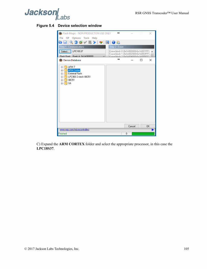
RSR GNSS Transcoder™ User Manual
Figure 5.4 Device selection window
C) Expand the ARM CORTEX folder and select the appropriate processor, in this case the LPC18S37.
© 2017 Jackson Labs Technologies, Inc. 105
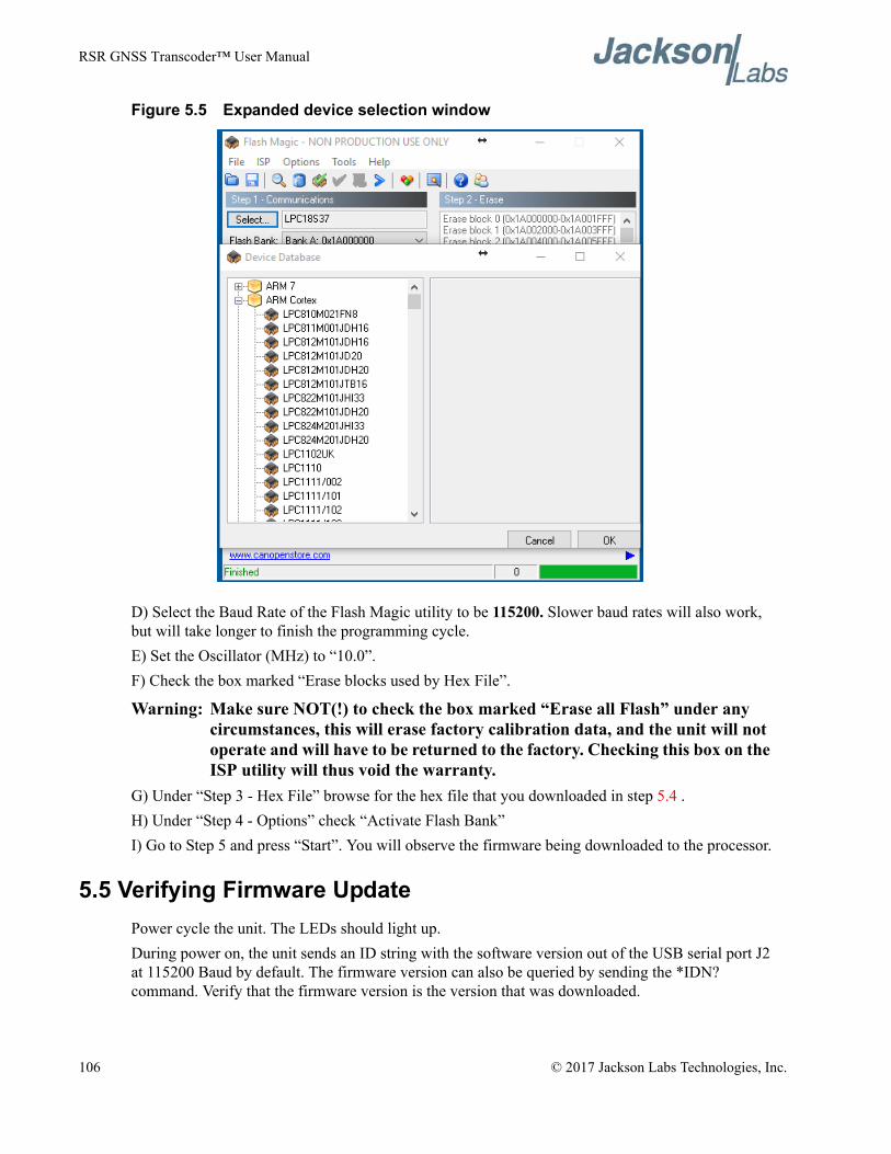
RSR GNSS Transcoder™ User Manual
Figure 5.5 Expanded device selection window
D) Select the Baud Rate of the Flash Magic utility to be 115200. Slower baud rates will also work, but will take longer to finish the programming cycle. E) Set the Oscillator (MHz) to “10.0”.F) Check the box marked “Erase blocks used by Hex File”.
Warning: Make sure NOT(!) to check the box marked “Erase all Flash” under any circumstances, this will erase factory calibration data, and the unit will not operate and will have to be returned to the factory. Checking this box on the ISP utility will thus void the warranty.
G) Under “Step 3 - Hex File” browse for the hex file that you downloaded in step 5.4 .H) Under “Step 4 - Options” check “Activate Flash Bank”I) Go to Step 5 and press “Start”. You will observe the firmware being downloaded to the processor.
5.5 Verifying Firmware UpdatePower cycle the unit. The LEDs should light up.During power on, the unit sends an ID string with the software version out of the USB serial port J2 at 115200 Baud by default. The firmware version can also be queried by sending the *IDN? command. Verify that the firmware version is the version that was downloaded.
106 © 2017 Jackson Labs Technologies, Inc.
RSR GNSS Transcoder™ User Manual
GPSCon Utility
6.1 DescriptionGPSCon - Jackson Labs Edition is a program for the monitoring and control of a Jackson Labs Technologies, Inc. GPSDO, Simulator and receiver products. It communicates with the receiver using the SCPI command set. A free version of the GPSCon utility is compatible with Jackson Labs products and is available for download from the support section of the Jackson Labs website:
http://www.jackson-labs.com/index.php/support
6.2 InstallationExtract the contents of the ZIP file downloaded from the Jackson Lab’s website and execute the MSI installer. Follow the on-screen instructions to complete the installation of GPSCon.
6.3 Using GPSConThe GPSCon utility has a help file that should be consulted in order to get the full functionality of this utility. Only a few of the features and commands are mentioned in this appendix for convenience.
6.3.1 Setting the optionsTo set up the options for your GPSCon session, press the wrench icon under the menu bar, or select Settings / Options on the menu. The window shown in Figure 6.1 will appear. You can select from the tabs which options you wish to set.
© 2017 Jackson Labs Technologies, Inc. 107
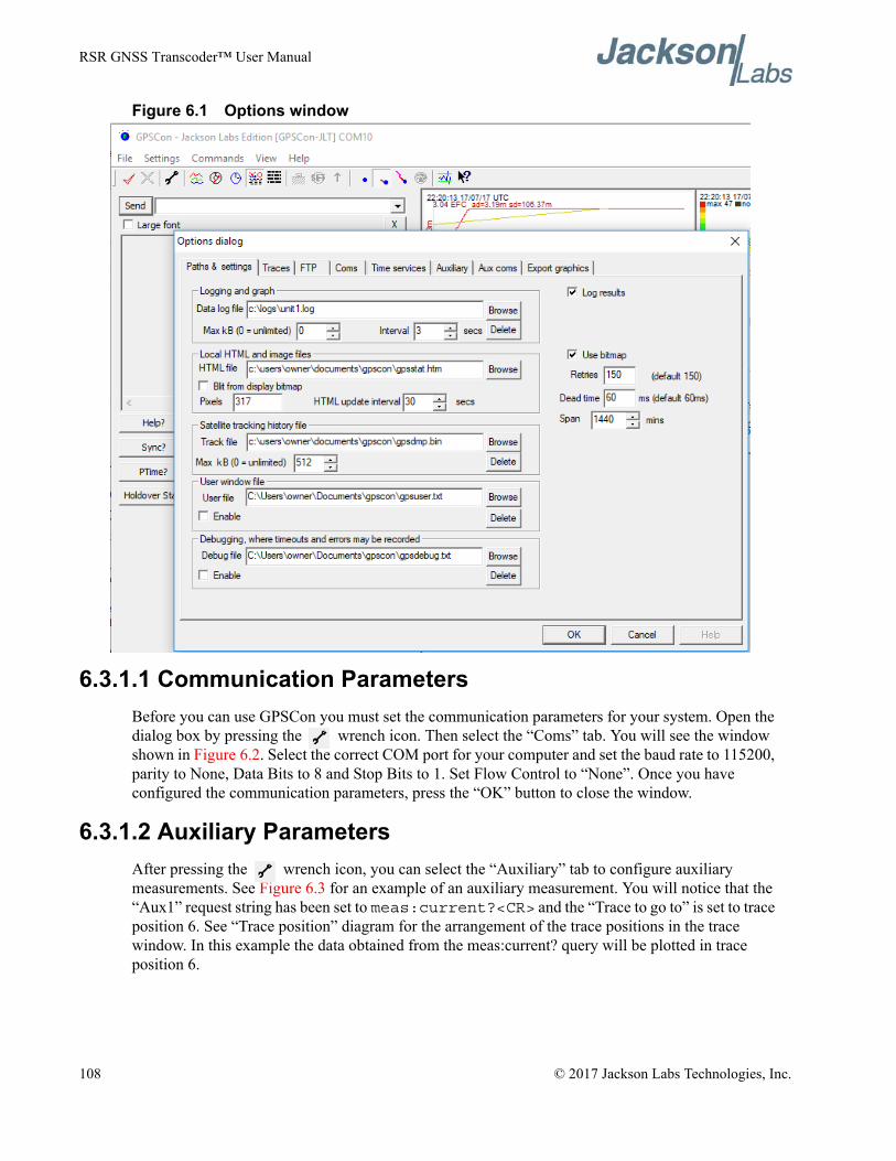
RSR GNSS Transcoder™ User Manual
Figure 6.1 Options window
6.3.1.1 Communication ParametersBefore you can use GPSCon you must set the communication parameters for your system. Open the dialog box by pressing the wrench icon. Then select the “Coms” tab. You will see the window shown in Figure 6.2. Select the correct COM port for your computer and set the baud rate to 115200, parity to None, Data Bits to 8 and Stop Bits to 1. Set Flow Control to “None”. Once you have configured the communication parameters, press the “OK” button to close the window.
6.3.1.2 Auxiliary ParametersAfter pressing the wrench icon, you can select the “Auxiliary” tab to configure auxiliary measurements. See Figure 6.3 for an example of an auxiliary measurement. You will notice that the “Aux1” request string has been set to meas:current?<CR> and the “Trace to go to” is set to trace position 6. See “Trace position” diagram for the arrangement of the trace positions in the trace window. In this example the data obtained from the meas:current? query will be plotted in trace position 6.
108 © 2017 Jackson Labs Technologies, Inc.
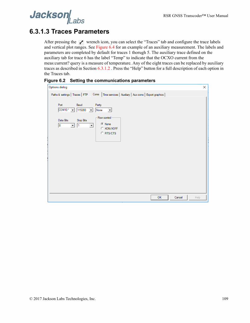
RSR GNSS Transcoder™ User Manual
6.3.1.3 Traces ParametersAfter pressing the wrench icon, you can select the “Traces” tab and configure the trace labels and vertical plot ranges. See Figure 6.4 for an example of an auxiliary measurement. The labels and parameters are completed by default for traces 1 thorugh 5. The auxiliary trace defined on the auxiliary tab for trace 6 has the label “Temp” to indicate that the OCXO current from the meas:current? query is a measure of temperature. Any of the eight traces can be replaced by auxiliary traces as described in Section 6.3.1.2 . Press the “Help” button for a full description of each option in the Traces tab.Figure 6.2 Setting the communications parameters
© 2017 Jackson Labs Technologies, Inc. 109
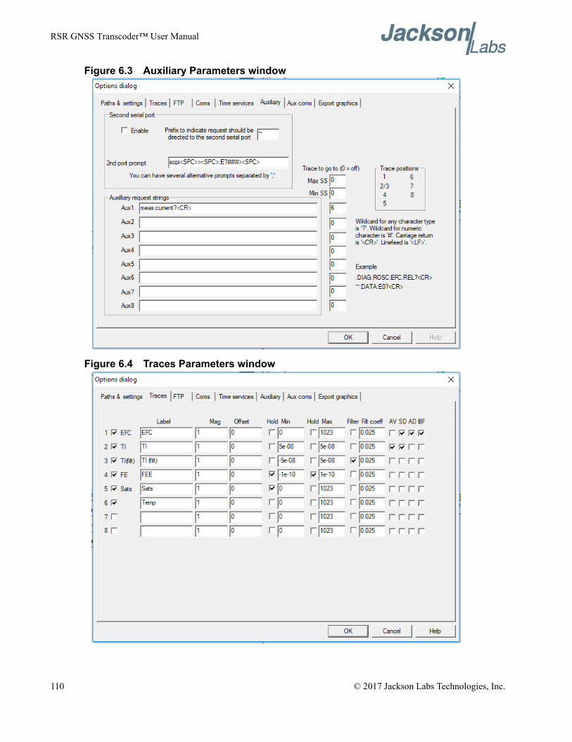
RSR GNSS Transcoder™ User Manual
Figure 6.3 Auxiliary Parameters window
Figure 6.4 Traces Parameters window
110 © 2017 Jackson Labs Technologies, Inc.
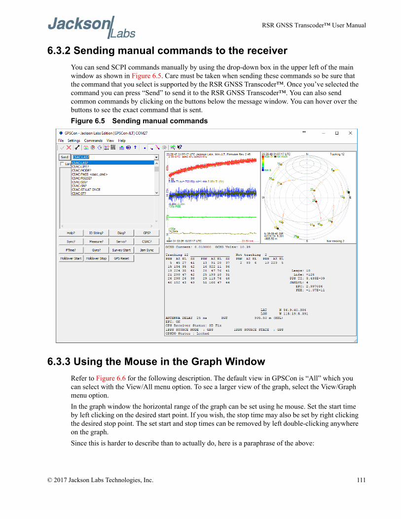
RSR GNSS Transcoder™ User Manual
6.3.2 Sending manual commands to the receiverYou can send SCPI commands manually by using the drop-down box in the upper left of the main window as shown in Figure 6.5. Care must be taken when sending these commands so be sure that the command that you select is supported by the RSR GNSS Transcoder™. Once you’ve selected the command you can press “Send” to send it to the RSR GNSS Transcoder™. You can also send common commands by clicking on the buttons below the message window. You can hover over the buttons to see the exact command that is sent.Figure 6.5 Sending manual commands
6.3.3 Using the Mouse in the Graph WindowRefer to Figure 6.6 for the following description. The default view in GPSCon is “All” which you can select with the View/All menu option. To see a larger view of the graph, select the View/Graph menu option.In the graph window the horizontal range of the graph can be set using he mouse. Set the start time by left clicking on the desired start point. If you wish, the stop time may also be set by right clicking the desired stop point. The set start and stop times can be removed by left double-clicking anywhere on the graph.Since this is harder to describe than to actually do, here is a paraphrase of the above:
© 2017 Jackson Labs Technologies, Inc. 111
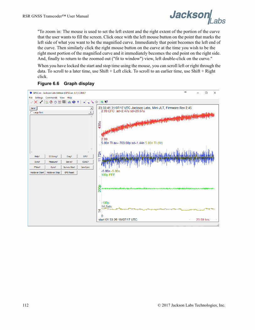
RSR GNSS Transcoder™ User Manual
"To zoom in: The mouse is used to set the left extent and the right extent of the portion of the curve that the user wants to fill the screen. Click once with the left mouse button on the point that marks the left side of what you want to be the magnified curve. Immediately that point becomes the left end of the curve. Then similarly click the right mouse button on the curve at the time you wish to be the right most portion of the magnified curve and it immediately becomes the end point on the right side. And, finally to return to the zoomed out ("fit to window") view, left double-click on the curve."When you have locked the start and stop time using the mouse, you can scroll left or right through the data. To scroll to a later time, use Shift + Left click. To scroll to an earlier time, use Shift + Right click.Figure 6.6 Graph display
112 © 2017 Jackson Labs Technologies, Inc.
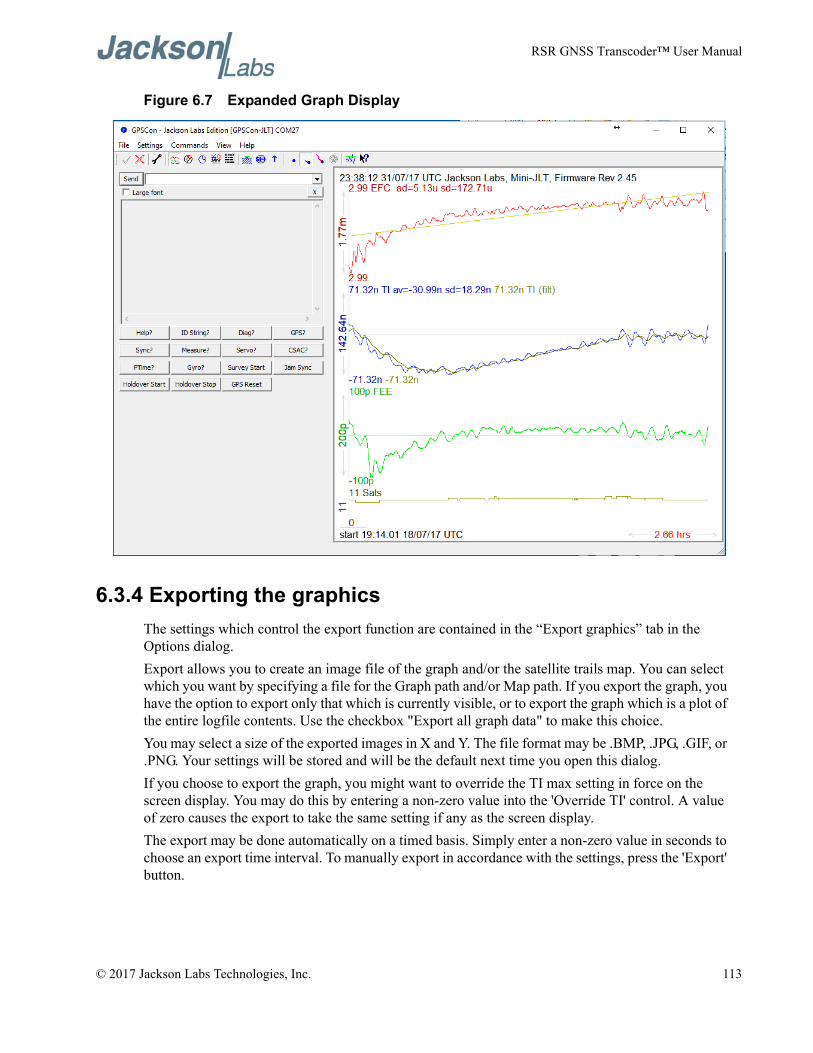
RSR GNSS Transcoder™ User Manual
Figure 6.7 Expanded Graph Display
6.3.4 Exporting the graphicsThe settings which control the export function are contained in the “Export graphics” tab in the Options dialog.Export allows you to create an image file of the graph and/or the satellite trails map. You can select which you want by specifying a file for the Graph path and/or Map path. If you export the graph, you have the option to export only that which is currently visible, or to export the graph which is a plot of the entire logfile contents. Use the checkbox "Export all graph data" to make this choice.You may select a size of the exported images in X and Y. The file format may be .BMP, .JPG, .GIF, or .PNG. Your settings will be stored and will be the default next time you open this dialog.If you choose to export the graph, you might want to override the TI max setting in force on the screen display. You may do this by entering a non-zero value into the 'Override TI' control. A value of zero causes the export to take the same setting if any as the screen display.The export may be done automatically on a timed basis. Simply enter a non-zero value in seconds to choose an export time interval. To manually export in accordance with the settings, press the 'Export' button.
© 2017 Jackson Labs Technologies, Inc. 113
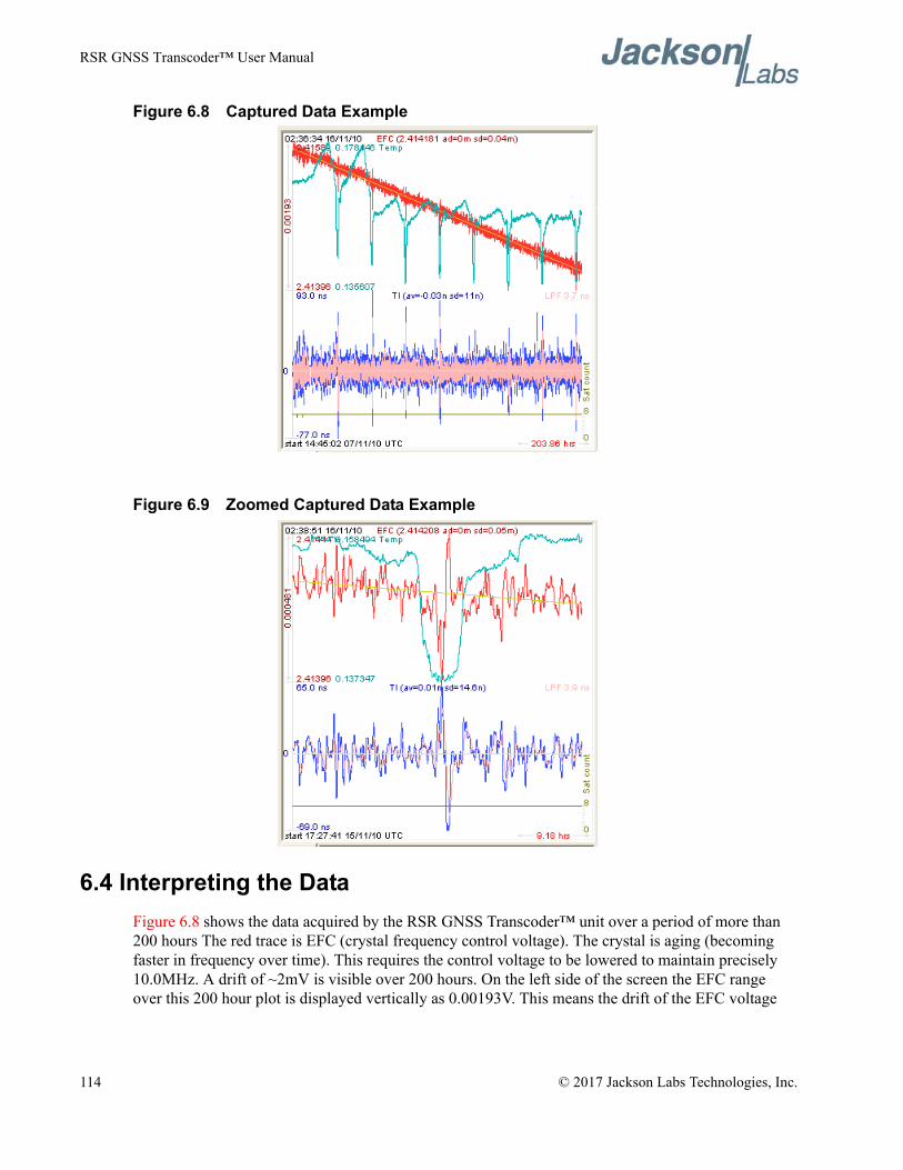
RSR GNSS Transcoder™ User Manual
Figure 6.8 Captured Data Example
Figure 6.9 Zoomed Captured Data Example
6.4 Interpreting the DataFigure 6.8 shows the data acquired by the RSR GNSS Transcoder™ unit over a period of more than 200 hours The red trace is EFC (crystal frequency control voltage). The crystal is aging (becoming faster in frequency over time). This requires the control voltage to be lowered to maintain precisely 10.0MHz. A drift of ~2mV is visible over 200 hours. On the left side of the screen the EFC range over this 200 hour plot is displayed vertically as 0.00193V. This means the drift of the EFC voltage
114 © 2017 Jackson Labs Technologies, Inc.
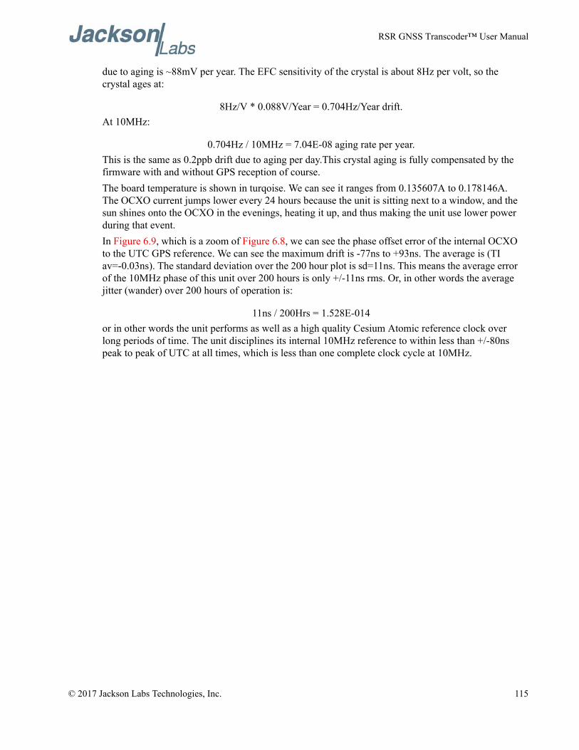
RSR GNSS Transcoder™ User Manual
due to aging is ~88mV per year. The EFC sensitivity of the crystal is about 8Hz per volt, so the crystal ages at:
8Hz/V * 0.088V/Year = 0.704Hz/Year drift.At 10MHz:
0.704Hz / 10MHz = 7.04E-08 aging rate per year.This is the same as 0.2ppb drift due to aging per day.This crystal aging is fully compensated by the firmware with and without GPS reception of course.The board temperature is shown in turqoise. We can see it ranges from 0.135607A to 0.178146A. The OCXO current jumps lower every 24 hours because the unit is sitting next to a window, and the sun shines onto the OCXO in the evenings, heating it up, and thus making the unit use lower power during that event.In Figure 6.9, which is a zoom of Figure 6.8, we can see the phase offset error of the internal OCXO to the UTC GPS reference. We can see the maximum drift is -77ns to +93ns. The average is (TI av=-0.03ns). The standard deviation over the 200 hour plot is sd=11ns. This means the average error of the 10MHz phase of this unit over 200 hours is only +/-11ns rms. Or, in other words the average jitter (wander) over 200 hours of operation is:
11ns / 200Hrs = 1.528E-014or in other words the unit performs as well as a high quality Cesium Atomic reference clock over long periods of time. The unit disciplines its internal 10MHz reference to within less than +/-80ns peak to peak of UTC at all times, which is less than one complete clock cycle at 10MHz.
© 2017 Jackson Labs Technologies, Inc. 115
RSR GNSS Transcoder™ User Manual
116 © 2017 Jackson Labs Technologies, Inc.

RSR GNSS Transcoder™ User Manual
Certification and Warranty
7.1 CertificationJackson Labs Technologies, Inc. certifies that this product met its published specifications at time of shipment.
7.1.1 WarrantyThis Jackson Labs Technologies, Inc. hardware product is warranted against defects in material and workmanship for a period of 1 (one) year from date of delivery. During the warranty period Jackson Labs Technologies, Inc. will, at its discretion, either repair or replace products that prove to be defective. Jackson Labs Technologies, Inc. does not warrant that the operation for the software, firmware, or hardware shall be uninterrupted or error free even if the product is operated within its specifications.For warranty service, this product must be returned to Jackson Labs Technologies, Inc. or a service facility designated by Jackson Labs Technologies, Inc. Customer shall prepay shipping charges (and shall pay all duties and taxes) for products returned to Jackson Labs Technologies, Inc. for warranty service. Except for products returned to Customer from another country, Jackson Labs Technologies, Inc. shall pay for return of products to Customer. If Jackson Labs Technologies, Inc. is unable, within a reasonable time, to repair or replace any product to condition as warranted, the Customer shall be entitled to a refund of the purchase price upon return of the product to Jackson Labs Technologies, Inc.
7.1.2 Limitation of WarrantyThe foregoing warranty shall not apply to defects resulting from improper or inadequate maintenance by the Customer, Customer-supplied software or interfacing, unauthorized modification or misuse, opening of the instruments enclosure or removal of the instruments panels, operation outside of the environmental or electrical specifications for the product, or improper site preparation and maintenance. JACKSON LABS TECHNOLOGIES, INC. SPECIFICALLY DISCLAIMS THE IMPLIED WARRANTIES OF MERCHANTABILITY AND FITNESS FOR A PARTICULAR
© 2017 Jackson Labs Technologies, Inc. 117
RSR GNSS Transcoder™ User Manual
PURPOSE. No license, express or implied, by estoppel or otherwise, to any intellectual property rights is granted by this document. Jackson Labs Technologies, Inc. products are not intended for use in medical, life saving, or life sustaining applications.
7.1.3 Exclusive RemediesTHE REMEDIES PROVIDED HEREIN ARE THE CUSTOMER'S SOLE AND EXCLUSIVE REMEDIES. JACKSON LABS TECHNOLOGIES, INC. SHALL NOT BE LIABLE FOR ANY DIRECT, INDIRECT, SPECIAL, INCIDENTAL, OR CONSEQUENTIAL DAMAGES, WHETHER BASED ON CONTRACT, TORT, OR ANY OTHER LEGAL THEORY.
118 © 2017 Jackson Labs Technologies, Inc.


![Cloud Transcoder: Bridging the Format and Resolution Gap between Internet Videos …net.pku.edu.cn/~lzh/papers/[NOSSDAV'12] Cloud Transcoder... · 2012-06-08 · Cloud Transcoder:](https://static.documents.pub/doc/80x56/5e694ca3d7372a772808bcd4/cloud-transcoder-bridging-the-format-and-resolution-gap-between-internet-videos.jpg)


