1. GENERAL Dataprobe’s RSS Redundancy Switch Systems provide high density relay based A/B switching for multiple circuits. Two chassis systems are available to accommodate large and small applications. Each system uses the same plug in cards, providing switching for up to 32 circuits in a single chassis. Both systems offers gang (simultaneous) switching as well as individual control of each A/B card. Dataprobe's RSS Series rack mounting chassis are available in two models; RSS-16 and RSS-3. The RSS-16 supports up to 16 AB switch cards, 2 control interface cards and 2 internal power supply modules in a compact 4U high, 19 inch chassis. The RSS-3 supports up to 3 AB switch cards, 1 control interface card and 1 internal power supply module, in a 1U chassis with removable rack mount brackets. Both chassis also provides access to local control switches for each of the A/B switch cards and viewing of their A/B status LEDs. Information in this manual applies to both systems except where specifically indicated. Power Supply modules are available for 100 -240 VA/C , 50-60Hz and 48 VDC power sources. Two modules can be installed in the chassis. In addition, external 24 V dc power supplies are available as an alternative to the internal power module or to provide redundant power. RSS Series Redundancy Switch Systems Installation and Operation
Transcript
1. GENERAL
Dataprobe’s RSS Redundancy Switch Systems provide high density relay based A/B switching for multiple circuits. Two chassis systems are available to accommodate large and small applications. Each system uses the same plug in cards, providing switching for up to 32 circuits in a single chassis. Both systems offers gang (simultaneous) switching as well as individual control of each A/B card. Dataprobe's RSS Series rack mounting chassis are available in two models; RSS-16 and RSS-3. The RSS-16 supports up to 16 AB switch cards, 2 control interface cards and 2 internal power supply modules in a compact 4U high, 19 inch chassis. The RSS-3 supports up to 3 AB switch cards, 1 control interface card and 1 internal power supply module, in a 1U chassis with removable rack mount brackets. Both chassis also provides access to local control switches for each of the A/B switch cards and viewing of their A/B status LEDs. Information in this manual applies to both systems except where specifically indicated. Power Supply modules are available for 100 -240 VA/C , 50-60Hz and 48 VDC power sources. Two modules can be installed in the chassis. In addition, external 24 V dc power supplies are available as an alternative to the internal power module or to provide redundant power.
RSS Series Redundancy Switch Systems
Installation and Operation
RSS_v180808n RSS Series Page 2
Table of Contents
1. GENERAL 1 Table of Contents 2 2. Chassis 3
2.1. RSS-16 Chassis 3 2.2. Important Notice: 3 Avis Important: 3 2.3. RSS-3 Chassis 4 2.4. Power Supply Indicators 4 2.5. A/B Card Status Indicators 5 2.6. A/B Card Manual Toggle Switches 5 2.7. Gang Control Switches RSS-16 5 2.8. Filler Panels 5
3. Power Supplies 6 3.1. Power Supply 1930084 6 3.2. Power Supply 1930083 7 3.3. Power Supply 1930086 7 3.4. Power Supply Installation 8 3.5. 24VDC Power Connection 9
4. IPC-16-R Control Card 10 4.1. Dual Control Cards RSS-16 10 4.2. IPC-16-R Installation 11 4.3. Serial Port 11 4.5. Command Line Interface 12 4.6. Telnet 12 4.7. Serial Port 12 4.8. SNMP 12 4.9. Command Line Interface 12 4.10. Configuration – IPC-16-R 13 4.11. Setting other Parameters 14 4.12. Operation 15
4.13. Command Line Interface 16 4.14. Web Browser Operation 21 4.15. SNMP Manager Control 23 4.16. Escape Sequence Control 23
Item # 1150101 The RSS-16 Chassis mounts in standard 19” equipment cabinets. Power supplies, control cards and switch cards install from the rear of the chassis. Install each card with the components facing left. The chassis and cards are keyed to prevent incorrect insertion. Switch cards may be inserted and removed with the power on (hot insertion/removal). Cards are secured in chassis with screws at the top and bottom of each panel. 19" W x 7.0" H x 7" D Weigh 12.5 Lbs (w/o cards)
2.2. Important Notice: Avis Important:
An appropriate fire and electrical enclosure should be provided in the end product for the top and bottom openings.
Un incendie approprié et armoire électrique doivent être fournis dans le produit final pour les ouvertures supérieure et inférieure.
If any of the card slots, including power supply slots, are not being used they are to be replaced with the appropriate blank plates so that the enclosure is completely closed.
Si l'une des fentes de cartes, y compris les emplacements d'alimentation, ne sont pas utilisés, ils doivent être remplacés par les plaques vierges appropriées pour que l'enceinte est complètement fermé.
Operators are not permitted access to the internals of the chassis. Only Service person shall remove covers and replace cards.
Les opérateurs ne sont pas autorisés à accéder aux éléments internes du châssis. Seulement personne Service doit enlever les couvercles et remplacer les cartes.
RSS_v180808n RSS Series Page 4
Note for serviceperson/technician: The symbol left (exclamation point in a triangle) indicates that energy hazards could be possible on the backplane. The symbol is located on the inside of the chassis near every other A/B switch connector.
This symbol located by the power inlets indicates that these devices may have multiple power sources. It is required that all power sources shall be disconnected before servicing to avoid shock hazard
Remarque pour préposé à l'entretien / technicien: Le symbole à gauche (point dans un triangle d'exclamation) indique que les dangers de l'énergie pourrait être possible sur le fond de panier. Le symbole est situé à l'intérieur du châssis à proximité de chaque autre connecteur du commutateur A / B. Ce symbole situé par les entrées d'alimentation indique que ces dispositifs peuvent avoir plusieurs sources d'alimentation. Il est nécessaire que toutes les sources d'alimentation doivent être déconnectés avant l'entretien pour éviter tout risque de choc.
2.3. RSS-3 Chassis
Item # 1150102 The RSS-3 Chassis mounts in standard 19” equipment cabinets. Rack mounting brackets provided, can be attached to the chassis sides for front or rear rail installations, or removed for non rack applications. Power supplies, control cards and switch cards install from the rear of the chassis. Install each card into the guide slots with the components facing upwards. The chassis and cards are keyed to prevent incorrect insertion. Switch cards may be inserted and removed with the power on (hot insertion/removal). Cards are secured in chassis with screws at right and left of each panel. 19" W x 1.75" H x 7" D Weigh 3.5 lbs. (w/o cards)
2.4. Power Supply Indicators The Chassis has two LED indicators that display the current status of two power supply sources. These are designated PS-1 and PS-2. LED on Indicates the power supply source is connected. PS-1 Internal Power Supply Module, or External Power Supply #1 PS-2 Internal Power Supply Module, or External Power Supply #2
2.5. A/B Card Status Indicators Each A/B switch card has LED indicators that can be viewed from the front panel of each chassis. When an A/B Switch is installed, the LEDs for that slot will be either A or B to indicate the status of the card. With no A/B Switch installed, there will be no LEDs to view.
2.6. A/B Card Manual Toggle Switches Each A/B switch card has al toggle switch for local control. The switches are accessed thru slots in the chassis front panel. These are momentary switches. Move the toggle up to select the A position of the card or down for the B position. With no card in a slot, there will be no toggle switch.
2.7. Gang Control Switches RSS-16 The RSS-16 chassis has three pushbutton switches for simultaneously controlling all A/B cards in the chassis. To perform control, hold down the pushbutton marked Enable while pressing either the A or B pushbutton to operate the switches. In multi-chassis systems, the master chassis (containing the control card), these pushbuttons will operate all A/B Cards in the system. In subsequent chassis, these pushbuttons will operate only the cards in that specific chassis.
2.8. Filler Panels Blank Filler Panels - #1920128 Blank panels are available for covering and shielding unused card slots. Filler panels are required for unused slots to meet UL and CE requirements.
RSS_v180808n RSS Series Page 6
3. Power Supplies
The RSS chassis supports both internal and external power supplies, allowing a wide assortment of combinations for flexibility and redundancy. Internal power modules are available to support worldwide A/C power, -48VDC and +24VDC external power supplies. External power supplies provide redundancy either when used in pairs, or when combined with an internal module.
Internal Power Supplies Dataprobe offers the following internal supply modules for the RSS series: 1930084 100 – 240 VAC, 50-60 Hz 1930083 100 – 240 VAC, 50-60 Hz – Power Factor Corrected 1930086 42 – 60 VDC 1930081 24 VDC External Connection Panel, Dual Inputs
3.1. Power Supply 1930084 Converts 110/ 220 /240 VAC to 24VDC Single Slot Redundant Capable
3.1.1. INPUT POWER Nominal : 120/240 VAC 50/60 Hz Range : 100 - 240 VAC Watts: 50 Fusing: 2 A
3.1.2. ENVIRONMENTAL Operating: 0 C - + 50 C
3.1.3. PHYSICAL Plug in rack card installs from rear of chassis
3.1.4. AC Input connector: IEC 320 (C14) on rear panel
3.3.6. Restricted Access Location This power supply must be installed in restricted access areas such as dedicated equipment room, or electrical closet, in accordance with United States National Electrical Code. A RESTRICTED ACCESS LOCATION is a location for equipment where both of the following apply:
• Access can only be gained by service persons or by users who have been instructed about the reasons for the restrictions applied to the location and about any precautions that shall be taken; and
• Access is through the use of a tool or lock and key, or other means of security, and is controlled by the authority responsible for the location.
3.4. Power Supply Installation Power Supplies insert into the chassis from the rear. An LED indicator on the front panel of the chassis displays power supply operation. Insert the power supply card in chassis prior to applying power.
3.4.1. RSS-3 The RSS-3 chassis supports one internal power supply installed thru the rear of the chassis, or an external 24VDC power supply can also be used by installing the 24 VDC External Connection Panel item 1930081. Redundant power can be added by connecting an external power supply to the DC power connector provided on the control card using Connector Kit item 1940164. LED indicators on the chassis front panel display the operating status of PS1 or PS2. The PS2 indicator only functions when an external power supply is added for redundancy.
3.4.2. RSS-16 Power Supply Options The RSS-16 can be configured for redundant power by using internal or external power supplies. Two internal power supply cards can be installed in the single slot power supply position in any combination of AC and DC models. The various configurations are shown below. Insert the card into the desired power supply position from the rear of the chassis. PS1 is the top position and PS2 is the bottom position A blank power card panel is included with the chassis when only one of the redundant supplies is installed. This panel should be kept for future use when two supply cards are installed should the need for removal of one of the supplies become necessary.
3.4.3. RSS-3 Power Supply Options The RSS-3 provides one power supply bay any power supply. For redundant power, add the external power supply 1930076. Connection to an external power supply can be made via the 24VDC power input on control cards IOC-3, IPC-1 or IPC-16, or the External 24VDC Connection Panel 1930081.
RSS_v180808n RSS Series Page 9
+_23
46
Rear ViewPin1 +24VDCPin5 - Return
3.5. 24VDC Power Connection The RSS-3 can be powered from an external 24VDC supply, Dataprobe Item # 1930076, or other 24 VDC, 2.5 A source using an RSS DC Power Connector Kit Item #1940164. Two power Inputs are provided for redundant power capability. Wiring detail is shown below. Note: The two inputs are isolated but will appear as PS1 on the front panel LED indicator and thru the Power Supply Status when using the IPC-16 control card. PS2 indicates the status of an external power supply connected to the control or gang expansion card option.
3.5.1. EXTERNAL 24VDC POWER WIRING
3.5.2. 24VDC Wiring Requirements Minimum Wire Rating: 14 AWG (1.63mm), 75 Deg C, 48VDC Maximum DC Mains Branch Circuit Protection : 3.5 A
3.5.3. Restricted Access Location Use of the 24VDC connections requires the system must be installed in restricted access areas such as dedicated equipment room, or electrical closet, in accordance with the United States National Electrical Code. A RESTRICTED ACCESS LOCATION is a location for equipment where both of the following apply:
• Access can only be gained by service persons or by users who have been instructed about the reasons for the restrictions applied to the location and about any precautions that shall be taken; and
• Access is through the use of a tool or lock and key, or other means of security, and is controlled by the authority responsible for the location.
3.5.4. Alarm Connector Alarm Connection on internal power supply modules provides status information on the condition of the supply.
9 Pin D-Sub Wiring
Pin 6 NO Pin 6 shorts to Pin 7 when the Power Supply is Non-Operational Pin 7 COM Pin 8 NC Pin 8 shorts to Pin 7 when the Power Supply is Operational
RSS-PAM-R Power Supply #2: Pin 3 NO Pin 3 shorts to Pin 4 when the Power Supply is Non-Operational Pin 4 COM Pin 5 NC Pin 5 shorts to Pin 4 when the Power Supply is Operational
RSS_v180808n RSS Series Page 10
4. IPC-16-R Control Card
Item # 1340065 Two Control Cards are available for use in the RSS systems; IPC-16-R and IPC-1-R , providing remote access control through network in-band and serial out-of-band circuits. IPC-16-R: Both Ethernet TCP/IP and Serial Connections, Individual and Gang AB card control IPC-1-R: Ethernet TCP/IP, Gang Control Only, WEB Through a web browser interface, you can access the control card, obtain current status information and operate the A/B Switches SNMP The system can be managed by SNMP through standard management software. Dataprobe provides a private MIB. Telnet– IPC-16-R Only Through a telnet client, you can access the control card, obtain current status information and operate the A/B Switches. This is also the method for setting configuration parameters of the card TCP Messaging – IPC-16-R Only A direct TCP messaging protocol is supported for direct computer control of the A/B switching system. Serial – IPC-16-R Only The serial port on the IPC-16-R provides direct terminal access or via modem. The A/B Cards are controlled either by a menu selection or by command line strings (escape code sequences). Menu selections are ideal for easy operator interface and the escape code sequences streamline automated control.
4.1. Dual Control Cards RSS-16 The RSS-16 chassis has two control card slots for supporting either; two IPC-16-R networks control cards, or one IPC-16-R and either the IOC-16-R or IOC-1-R I/O access cards. When two network cards are installed both cards must be configured the same except for individual IP addresses. The user must also control network access to avoid any conflicts in control contention. Each controller provides pulsed control signals to the A/B switch cards. The switch cards will be positioned according to commands from the last network controller or I/O access card used. When a IPC-16-R Network control card and either IOC I/O access card is used, any contact closure externally provided thru the I/O access card will override the network control if the external contact is not momentary.
RSS_v180808n RSS Series Page 11
4.2. IPC-16-R Installation The IPC-16-R Control Card installs from the rear of the chassis in one of the two control card slots only. The slot are on the left (facing the rear), next to the power supply. Two IPC-16-R cards can be installed for redundant remote access. Note: It is recommended that any removal or insertion of a control card be performed with power off to prevent possible unintentional switching of the switch cards. The card provides the following connections: External Power Input. Connection for external power supply, singularly, or as a supplement to an internal supply for dual redundant power. Mating Connector kit # 1940164 Gang Expansion. RJ11 connection for connection to additional chassis for large gang switching applications. Serial Port. RS-232 port for out-of-band access to the IPC-16-R card. Ethernet. Network connection; 10baseT - IPC-16-R,
4.3. Serial Port The Serial Port on the control card is a 9 pin male connector, configured as a DTE. The following pins are used. The following chart illustrates the pin out of the D9 connector and the connection required to an external modem with a D25 pin out.
D9 Pin Abbreviation Full Name Modem D25 Pin
Pin 2 RD Receive Data Pin 3 Pin 3 TD Transmit Data Pin 2 Pin 5 SG Signal Ground Pin 7 Pin 9 RI Ring Indicator Pin 22
For connection directly to a terminal, a Null Modem cable is required.
IPC-16-R D9 Pin
Terminal D9 Pin
Pin 3 Pin 2 Pin 2 Pin 3 Pin 5 Pin 5
RSS_v180808n RSS Series Page 12
4.5. Command Line Interface The IPC-16-R is managed by a Command Line Interface (CLI) system via Telnet or Serial Port. The CLI uses a username password challenge for security.
4.5.1. Factory defaults System Chassis and RCU Username admin Password admin
4.6. Telnet The system supports the Telnet communications protocol for management access. Optionally, the telnet server in the IPC-16-Rcan be disabled with a CLI command. Connect via Telnet client to the IP address of the IPC-16-R
4.6.1. Factory Defaults • RSS IP Address 192.168.1.254
4.7. Serial Port To login in to the IPC-16-Rusing the serial port, set the terminal to the baud rate and character format, then send a Carriage Return <Enter key> . Baud Rate Baud rate choices are 9600, 19200, 38400, 57600 and 115200 bits per second. Character format is fixed at 8 Data Bits, No Parity, One Stop Bit. (8, N, 1)
4.7.1. Factory Defaults • 9600, 8 Data Bits, No Parity, One Stop Bit (9600,8,N,1)
4.8. SNMP The IPC-16-R system is SNMP manageable. Up to four SNMP managers can be defined for the purpose of delivering status Inform messages.
4.8.1. Factory Defaults • Read Community: public • Read/Write Community: private • Notification Timeout: 1 second • Notification Retry Count: 3 • Lead Configuration Change: 0 seconds
4.9. Command Line Interface
4.9.1. Initial connection To establish a connection to the system chassis via the network, open a telnet client to the IP address of the system. The session will begin upon connection. To access the system chassis via the serial port, connect a suitable dumb terminal, or system running terminal emulation to the serial port at the proper baud rate and character format. Send <Enter> via the serial port to begin the session.
RSS_v180808n RSS Series Page 13
Upon Connection the system will send the Model, Version and login prompt:
Hello... connected to RSS-16!
Connected to Telnet Session 2
User>
Enter the username. The system will then prompt for a password:
Password>
Enter the password. If successful, the system will send the system level prompt:
RSS-16>
4.9.2. CLI Navigation The system uses a tree structured navigation system. System level, indicated by the RSS-16> prompt set the or display the basic parameters for the IPC-16-R including all network configuration. To access any card level parameters, including the A/B status of the card, select the card with the select card command RSS-16> select card 3 RSS-16.Card 3> The prompt changes to indicate the current card selected. To return to the system level, send the exit command.
4.10. Configuration – IPC-16-R Configuration of the IPC-16-R involves the following steps: • Setting The IPC-16-R's IP Address • Setting additional configuration parameters.
4.10.1. Setting I/P Address The IPC-16-R comes with factory installed IP address 192.168.1.254. In most cases this will need to be changed. Consult your Network Administrator to determine the appropriate IP address. There are several methods to change the IP address. • ARP • Telnet • Serial Port • setip.exe program, available from Dataprobe’s web site To set the IP address, the hardware (MAC) address must be known. This address is located on a label on on the IPC-16-R printed circuit board. The syntax for the MAC address is: nn-nn-nn-nn-nn-nn
4.10.2. Setting the IP address using ARP To set the IP address using ARP, connect the jack marked 10Base-T to your local Ethernet network and apply power to the unit. The computer used to set the IP address must be on the same physical network as the IPC-16-R. ARP does not work across switched or routed networks.
4.10.3. Windows (98 and Later) 1. Open a DOS window.
RSS_v180808n RSS Series Page 14
2. Type the following command: arp -s <IP Address> <MAC Address> Where <IP Address> is the desired IP address (in dotted decimal) for the IPC-16-R and the <MAC address> is the MAC Address of the IPC-16-R. The MAC Address is located on a label on the rear panel of the card.
Example: arp -s 63.211.86.165 00-50-c2-05-01-c1 <enter> |--- new IP addr. ---| |------- MAC addr. ------|
3. Ping the IPC-16-R to program the IP address into the IPC-16-R. Type: ping <IP Address> If the ping command returns “host not responding” 4 times then the address has not been programmed properly, or the IP or MAC Address is incorrect. In either case redo step 2. If the problem persists, contact the Dataprobe Tech Support Hot Line.
4. Delete the entry from the ARP cache by typing: arp -d <IP Address>
5. Ping the IPC-16-R to confirm that it has been programmed. If the card fails to respond, repeat steps 2-4 above. If the problem persists contact the Dataprobe support hotline.
4.10.4. Unix, Linux Consult your systems administrator for information on setting an IP Address using ARP. The unit should be pinged after the IP Address has been set to confirm proper operation.
4.10.5. Setting IP Address with Telnet For initial setup, the computer used must use the same network segment as the default IP Address, or current IP address. (192.168.1.xxx) If this is not the case, use one of the other methods. To connect to the IPC-16-R using telnet, run your telnet client program (provided with your operating system) and connect to the IP address as set in step one above. For Windows: Select Run…Telnet Connect…192.168.1.254 (or the current IP address) As soon as you connect the following message will be displayed:
4.10.6. Setting IP address via Serial Port The serial port uses the same menu sequences as the Telnet method described above. Connect a terminal directly to the IPC-16-R serial port. Send an Enter keystroke to start the session. The serial port default settings are 9600bps, 8 data bits, no parity, one stop bit. These setting can also be changed via the menus.
4.10.7. Setting IP Address with setip.exe Utility setip.exe is available from Dataprobe’s website at http://dataprobe.com/support/rss/setip.exe. Download this windows program and run it on any computer on the same physical network segment as the control card. Enter the MAC address and desired IP address and press SetIP.
4.11. Setting other Parameters Via the Serial Port or telnet, all other configuration parameters can be set for the IPC-16-R. These setting are made from the Command Line Interface, as described in the section 4.13 . Some specific settings to consider are: Location Name: Enter a 1-20 character name to identify the system. This name appears at the top of each telnet screen and web page.
Card Setup: This allows setting of parameters for individual A/B cards in the system. Each card can be named, up to 20 characters, and can be enabled or disabled. Disabling a card hides its status from web and telnet screens. This should be used where no card is installed, to make reading the screens easier. Password: A password from 1 to 15 characters is needed for access to the system. Re-enter the old password then enter the new password twice as prompted. Com Port: Set the Baud Rate and Character Format for the serial port. Baud rate choices are 9600, 19200, and 38400. Character format choices are 8N1, 7E1 and 7O1 (databits, parity, stop bit). The Default Serial Port Parameters are 9600, 8 Data Bits, No Parity, One Stop Bit (9600,8,N,1) Escape Response: This selects Yes or No for escape code responses. See section 3.4.3 on escape code control Web Port, Telnet Port, Message Port: These three settings determine the port assignment for the different TCP protocols used to communicate with the control card. Standard port assignments for these protocols are:
WEB: 80 Telnet: 23 Message: 9100 If you change these assignments, you will need to specify them when you connect to the IPC-16-R. For example if the IP address of the IPC-16-R is 192.168.1.254 and you have changed the web port to 8800, then you would need the following URL to access the IPC-16-R: http://192.168.1.254:8800
Note: After changing the IP Address, Web Port, Telnet Port or Com Port parameters, it is necessary to reboot the IPC-16-R Card. Do this by entering selection “System Reset”, item 6 in the System Setup Menu displayed in the CLI during a Telnet session, or momentarily powering Off the power to the chassis power supply. Power cycling the power source to the chassis power supply will insure no unintentional changes in switch positions of any A/B Card in the chassis.
MTU: Maximum Transmission Unit. Set the MTU from 100 to 1024. The default of 1024 should not be changed unless required by network architecture. Read and Write Community Names: These settings are for use with SNMP managers only. Set the names as appropriate for your SNMP configuration. SNMP Managers: Set up to four SNMP managers that will receive SNMP TRAPs. Other SNMP managers will be able to manage the system.
4.12. Operation Remote control of each or all A/B Cards is accomplished using either TCP/IP protocols for Web browser (http) , Telnet, or direct TCP messaging. Each card in the chassis can be operated independently, or all 16 A/B cards can be operated simultaneously. In all cases, switch control is password protected.
RSS_v180808n RSS Series Page 16
4.13. Command Line Interface
4.13.1. System Level Commands
Command Description Default logout Log out of the system
reboot Reboot the system
get all Get system status RSS System: Network_Ops Power 1: Fail Power 2: Ok Controller F/W: v1.00.067 ID Name Enabled Act 1 NewYork Yes A 2 Boston Yes A 3 Providence Yes A 4 Philadelphia Yes A 5 Baltimore Yes B 6 WDC_East Yes A 7 WDC_West Yes A 8 Atlanta Yes A 9 Miami Yes B 10 Seattle Yes A 11 Portland Yes B 12 San_Francisco Yes A 13 Phoenix Yes B 14 Houston No - 15 Chicago No - 16 Pittsburgh No - Ok RSS-16>
select card <1-16> Moves to card level. Prompt changes to RSS.Card nn>
get location set location <0-20 characters>
Sets the displayed name of the chassis. 20 Characters maximum
Set Location
RSS_v180808n RSS Series Page 17
get powersupply Get the current state of the power supplies RSS-16> get powersupplies Power Supply 1: Fail Power Supply 2: Ok Ok RSS-16>
get upgrade enable set upgrade enable <yes|no>
Set firmware upgrade enable flag
no
get mac set mac <XX:XX:XX:XX:XX:XX>
Set network MAC address
get network Get network IP settings RSS-16> get network IP Mode: Static IP Address: 10.10.10.70 Subnet: 255.255.255.0 Gateway: 10.10.10.7 DNS1: 0.0.0.0 DNS2: 0.0.0.0 Ok RSS-16>
set ipmode <static|dhcp> Sets the IP Mode Static: The IP address is set manually DHCP: The IP Address is set by DHCP Server
static
set ipaddress <xxx.xxx.xxx.xxx> Sets the IP Address in dotted decimal 192.168.1.254
set subnet <xxx.xxx.xxx.xxx> Sets the subnet mask in dotted decimal 255.255.255.0
set gateway <xxx.xxx.xxx.xxx> Sets the gateway in dotted decimal 0.0.0.0
set dns1 <xxx.xxx.xxx.xxx> Set network DNS server 1 IP address 0.0.0.0 set dns2 <xxx.xxx.xxx.xxx> Set network DNS server 2 IP address 0.0.0.0
RSS_v180808n RSS Series Page 18
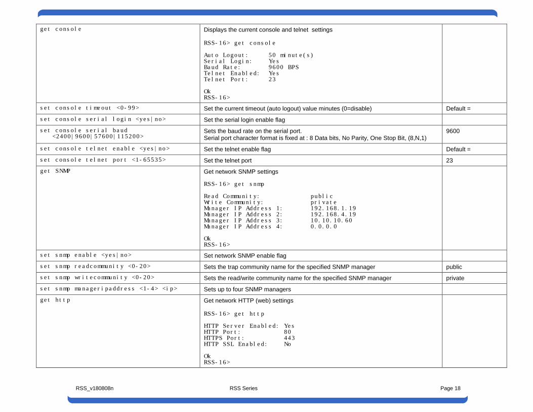
get console Displays the current console and telnet settings RSS-16> get console Auto Logout: 50 minute(s) Serial Login: Yes Baud Rate: 9600 BPS Telnet Enabled: Yes Telnet Port: 23 Ok RSS-16>
set console timeout <0-99> Set the current timeout (auto logout) value minutes (0=disable) Default =
set console serial login <yes|no> Set the serial login enable flag
set console serial baud <2400|9600|57600|115200>
Sets the baud rate on the serial port. Serial port character format is fixed at : 8 Data bits, No Parity, One Stop Bit, (8,N,1)
9600
set console telnet enable <yes|no> Set the telnet enable flag Default =
set console telnet port <1-65535> Set the telnet port 23 get SNMP Get network SNMP settings
RSS-16> get snmp Read Community: public Write Community: private Manager IP Address 1: 192.168.1.19 Manager IP Address 2: 192.168.4.19 Manager IP Address 3: 10.10.10.60 Manager IP Address 4: 0.0.0.0 Ok RSS-16>
set snmp enable <yes|no> Set network SNMP enable flag
set snmp readcommunity <0-20> Sets the trap community name for the specified SNMP manager public set snmp writecommunity <0-20> Sets the read/write community name for the specified SNMP manager private
set snmp manageripaddress <1-4> <ip> Sets up to four SNMP managers
get http Get network HTTP (web) settings RSS-16> get http HTTP Server Enabled: Yes HTTP Port: 80 HTTPS Port: 443 HTTP SSL Enabled: No Ok RSS-16>
RSS_v180808n RSS Series Page 19
set http enabled <yes|no> Set Web Server Enabled or Disabled yes
set http port <1-65535> Set network HTTP port 80
set http httpsport <1-65535> Set network HTTPS SSL port 443
set http usessl <yes|no> Set if Web Encryption, HTTPS is required no get escape Get escape sequence settings
RSS-16> get escape Escape Enabled: Yes Escape Port: 9100 Ok RSS-16>
set escape enabled <yes|no> Set escape sequence enable flag yes
set escape port <1-65535> Set escape sequence port 9100
set gang <a|b> Gang Switches all cards in system to A or B
set password <1-20> Set system password admin set factory defaults Set system to factory defaults
RSS_v180808n RSS Series Page 20
4.13.2. Card Level Commands 4.13.3.
Command Description Default get all Get card status and configuration
RSS-16.Card 1> get all Current Card Values: Card ID: 1 Card Name: NewYork Enabled: Yes Active Port: A Ok RSS-16.Card 1>
get name set name <0-20 characters >
Set card name ????
get enabled set enabled <yes|no>
Set card enabled flag yes
set type <empty|dumb> Set card type (empty means not populated) dumb
set activeport <a|b> Set active port status a exit Exit back to main level
RSS_v180808n RSS Series Page 21
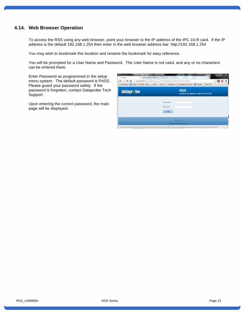
4.14. Web Browser Operation To access the RSS using any web browser, point your browser to the IP address of the IPC-16-R card. If the IP address is the default 192.168.1.254 then enter in the web browser address bar: http://192.168.1.254 You may wish to bookmark this location and rename the bookmark for easy reference. You will be prompted for a User Name and Password. The User Name is not used, and any or no characters can be entered there. Enter Password as programmed in the setup menu system. The default password is PASS. Please guard your password safely. If the password is forgotten, contact Dataprobe Tech Support. Upon entering the correct password, the main page will be displayed.
RSS_v180808n RSS Series Page 22
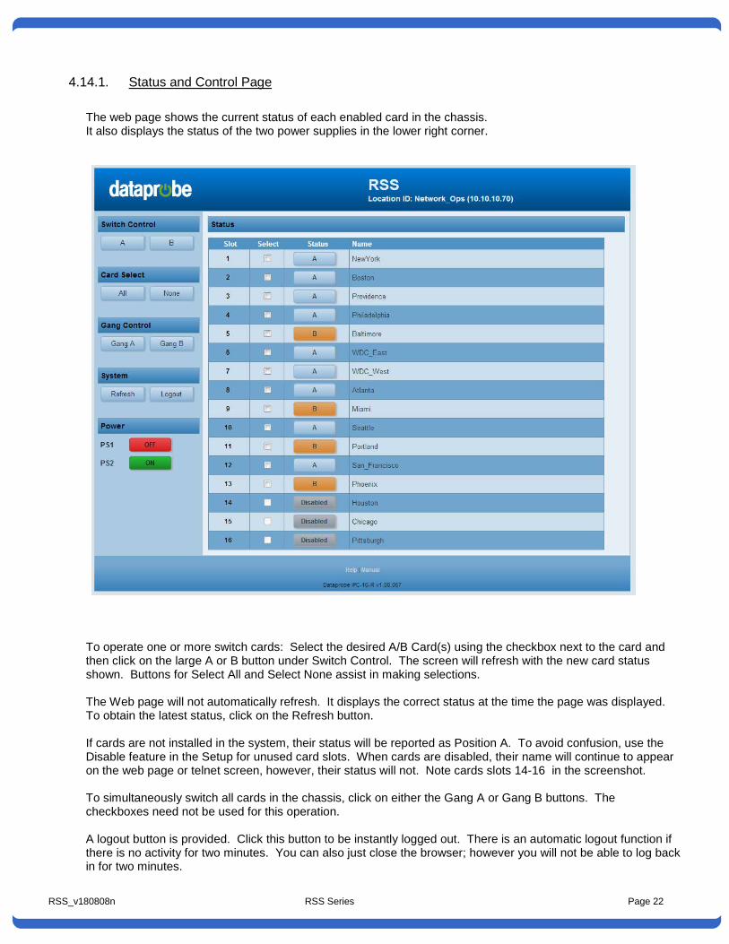
4.14.1. Status and Control Page The web page shows the current status of each enabled card in the chassis. It also displays the status of the two power supplies in the lower right corner.
To operate one or more switch cards: Select the desired A/B Card(s) using the checkbox next to the card and then click on the large A or B button under Switch Control. The screen will refresh with the new card status shown. Buttons for Select All and Select None assist in making selections. The Web page will not automatically refresh. It displays the correct status at the time the page was displayed. To obtain the latest status, click on the Refresh button. If cards are not installed in the system, their status will be reported as Position A. To avoid confusion, use the Disable feature in the Setup for unused card slots. When cards are disabled, their name will continue to appear on the web page or telnet screen, however, their status will not. Note cards slots 14-16 in the screenshot. To simultaneously switch all cards in the chassis, click on either the Gang A or Gang B buttons. The checkboxes need not be used for this operation. A logout button is provided. Click this button to be instantly logged out. There is an automatic logout function if there is no activity for two minutes. You can also just close the browser; however you will not be able to log back in for two minutes.
RSS_v180808n RSS Series Page 23
4.15. SNMP Manager Control The IPC-16-R allows for management via SNMP. The private MIB is available from the Dataprobe Web Site at: http://dataprobe.com/support-rss-series-welcome/ MIB Outline and MIB Definitions can be found in Section 9
4.16. Escape Sequence Control The IPC-16-R can be controlled via command line messages sent either over the serial port or using TCP messaging over the Ethernet port. This allows streamlined communication between the IPC-16-R and network management systems or computer based monitor and control systems. Programming support is available. Contact Dataprobe Applications Engineering.
4.16.1. Making Connection via Ethernet and Serial The IPC-16-R uses the TCP (Transport Communication Protocol) to communicate with the client PC. To use the IPC-16-R , establish a TCP connection (Stream Socket) to the IPC-16-R. Be sure to use the Port assigned to the IPC-16-R , either Port 9100 or the port assigned through the Setup Menus. Once connected use the Send() function to send the commands to the IPC-16-R and the Recv() function to receive the IPC-16-R ’s response. For the serial port of the IPC-16-R, connection via the serial port requires only setting the computer to the proper baud rate and character format.
4.16.2. Command Syntax
<esc><password><^a><card><^b><command><cr>
Where: esc = The ASCII escape character (0x1b) password = The IPC-16-R password in ASCII (case sensitive) ^a = The ASCII control 'a' character (0x01) card = The number of the card to be changed, with or with out leading 0's (a or A = all)\ ^b = The ASCII control 'b' character (0x02) command = The command to be executed: a or A - Switch selected card to A b or B - Switch selected card to B q or Q - Display the status of the selected card cr = The ASCII Carriage Return (0x0d) The < and > in the syntax above are only to delineate the control characters and should not be sent. Example: To switch card 7 to B send <esc>PASS<^a>7<^b>B<cr>
4.16.3. Response Syntax The syntax for the command response is. <card><status><cr> Example: 01A card = The number of the card. status = The status of the card either A, or B. cr = The ASCII carriage return character
If the queried card has been disabled then no response will be transmited. In response to the Query All command, 16 response messages will be sent. All invalid commands will be ignored. No response even when responses are enabled.
RSS_v180808n RSS Series Page 25
5. IPC-1-R Network Gang Control Card
Item # 1340066 The IPC-1-R Control Card installs from the rear of the chassis in the 2nd control card slot only. This is the third slot on the left (facing the rear), next to the power supply. The physical size of the IPC-1-R components require 2 slots. Note: It is recommended that any removal or insertion of a control card be performed with power off to prevent possible unintentional switching of the switch cards. The card provides the following connections: External Power Input. Connection for external power supply, singularly, or as a supplement to an internal supply for dual redundant power. Mating Connector kit # 1940164 Gang Expansion. RJ11 connection for connection to additional chassiss for large gang switching applications. Ethernet. 10/100base-T Network connection
5.1. IPC-1-R Configuration
5.1.1. Setting I/P Address IPC-1-R comes with factory installed IP address 192.168.1.254 you may need to change this address. Consult your Network Administrator to determine the appropriate IP address. The IP address can be set in any of four ways: • Web Browser via the Set-up Page • Automatically from a DHCP Server • ARP-Ping • Dataprobe setip.exe utility 1. Setting the IP address using Web Browser Access the IPC-1-R with the administrator credentials and select Setup, then IP. Enter the IP address, subnet mask and gateway. For initial setup the computer accessing the IPC-1-R needs to be on the same subnet as the IPC-1-R (have a 192.168.1.xx address) To lock the settings, select the IP Mode: Static. This prevents additional changes to be made with either DHCP or ARP. Click Apply and then a Reboot button will appear. Click to Reboot. The new changes will take effect after reboot. 2. Setting the IP address from a DHCP Server A DHCP server will automatically assign an IP address (dynamic address) as well as Subnet Mask and Gateway to the IPC-1-R. If you power up IPC-1-R with the IP Mode set to DHCP, the server will be able to assign an IP address. Once an IP address is assigned, you must check with the DHCP server to see what address is
RSS_v180808n RSS Series Page 26
assigned to IPC-1-R. Once the assignment is made, you can lock the settings, by accessing the IP setup page and selecting the IP Mode: Static. This prevents additional changes to be made with either DHCP or ARP-Ping.
To enable DHCP, access the Setup web page, then IP settings and select Mode DHCP. A reboot is required. 3. Setting the IP address using ARP-Ping To set the IP address using ARP, connect the ethernet connection to your network and apply power to IPC-1-R. Using ARP you use a computer to set the IP address. The IP address assigned to IPC-1-R must be use the same network segment as the computer assigning the address. ARP does not work across routed or switched networks. For security purposes, ARP-Ping will only work within the first two minutes of powering up the IPC-1-R. To set the IP address using ARP, the hardware (MAC) address is used. This address is located on the bottom of the unit. The syntax for the MAC address is: nn-nn-nn-nn-nn-nn
Windows Open a DOS window. 1. Type the following command:
arp -s <IP Address> <MAC Address> Where <IP Address> is the desired IP address (in dotted decimal) for the IPC-1-R and the <MAC address> is the MAC Address of the IPC-1-R. The MAC Address of the IPC-1-R is located on bottom of the unit.
Example: arp -s 192.168.7.203 00-50-c2-05-01-c1 <enter> |--- new IP addr. --| |------ MAC addr. ------|
2. Ping the IPC-1-R to program the IP address into the IPC-1-R by typing:
ping <IP Address> If the ping command returns “host not responding” 4 times then the address has not been programmed properly, or the IP Address is incorrect. In either case redo step 2. If the problem persists, contact the Dataprobe Tech Support Hot Line.
3. Delete the entry from the ARP cache by typing: arp -d <IP Address>
4. Ping the IPC-1-R (repeat step 2) to confirm that it has been programmed properly.
If the IPC-1-R fails to respond, repeat steps 2-4 above. If the problem persists contact the Dataprobe support hotline. To lock the settings, select the IP Mode: Static. This prevents additional changes to be made with either DHCP or ARP-Ping.
5.1.2. Setting the IP address setip.exe Dataprobe provides a utility program to streamline the setting of the IP address. This program duplicates the steps used in the ARP-Ping method above. Download this program at http://dataprobe.com/files/control/setip.exe. This windows program is self extracting file with the program and help file. The setip.exe program must be run from the same subnet as the IPC-1-R. As with ARP-Ping, the program must be run within 2 minutes of powering up the IPC-1-R.
5.2. Web Browser Operation 5.2.1. Password Protection:
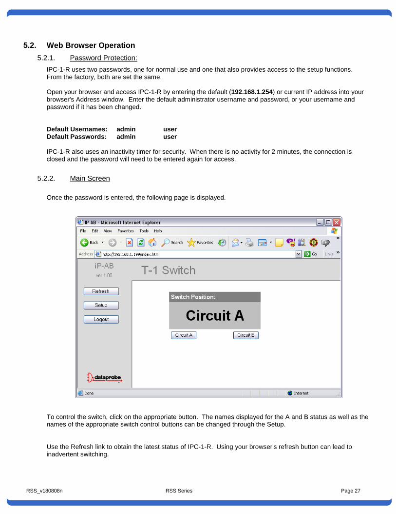
IPC-1-R uses two passwords, one for normal use and one that also provides access to the setup functions. From the factory, both are set the same. Open your browser and access IPC-1-R by entering the default (192.168.1.254) or current IP address into your browser's Address window. Enter the default administrator username and password, or your username and password if it has been changed. Default Usernames: admin user Default Passwords: admin user IPC-1-R also uses an inactivity timer for security. When there is no activity for 2 minutes, the connection is closed and the password will need to be entered again for access.
5.2.2. Main Screen Once the password is entered, the following page is displayed.
To control the switch, click on the appropriate button. The names displayed for the A and B status as well as the names of the appropriate switch control buttons can be changed through the Setup. Use the Refresh link to obtain the latest status of IPC-1-R. Using your browser's refresh button can lead to inadvertent switching.
RSS_v180808n RSS Series Page 28
When you are finished with IPC-1-R, click on Logout. A confirmation page will be displayed. If you close your browser windows without first clicking Logout, there will be a two minute delay before you can re-access IPC-1-R. IPC-1-R will automatically time out if there is no activity for two minutes. This is to prevent accidental lockout by leaving the browser open. If the Auto-Ping feature is in use, this page will also display its status, OK or Triggered, and the number of times it has been triggered. OK indicates that the IP address being pinged is responding. It will display Triggered to indicate that it has is not receiving a response to the pings, and has performed its programmed switching function. The Trigger Count indicates the number of times the IPC-1-R has been triggered. This counter can be reset with a button on the page.
RSS_v180808n RSS Series Page 29
5.3. Setup Page The setup page consists of several sections. Each time a setting is changed click on the Apply button for that section to save the changes in IPC-1-R.
Device Set the name that displays on the top of the Home Page as well as the Status Name for the A and B switch positions.
IP Set the IP address, IP acquisition mode, Port Settings and SSL AutoPing Set the IPC-1-R for automatic operation based on device availability SNMP Set up to 4 SNMP managers and what events generate Traps Passwords Set username and passwords for the Administrator and User E-mail Set email notification and what events generate emails Update Load new or custom firmware in the IPC-1-R
RSS_v180808n RSS Series Page 30
Device Device Name: Set the name to be displayed on the top of each web page. 20 Character Max. Status Name: Set the name displayed for the A and B switch status. 20 Character Max. IP IP address, Subnet Mask, Gateway: Enter these values as provided by your network administrator. IP Mode: Select the mode of acquiring the IP address.
Static Mode: Locks the IP address as shown above. When the IP number is Static, it can not be changed by DHCP or ARP-PING methods. If the IP number is forgotten, use the IP-AB recovery tool. See Troubleshooting.
DHCP Mode: Allows a DHCP server to assign IP address APR-PING Mode: Allows setting of the IP address via ARP/Ping method or using the ipset.exe utility.
HTTP Port: To access IPC-1-R on a port other than the Web standard 80. If the port is changed, you will need to identify the port number when you enter IPC-1-R's IP address into your browser: if the new port is 9100 then use http://192.168.1.254:9100 to access IPC-1-R. Dataprobe recommends changing of the port from the default 80 to reduce the number of attacks from hackers. SSL: The IPC-1-R can use Secure Socket Layer (SSL) encryption to protect the username/password and data between the browser and the switch. This is set Enabled by default. Disabling SSL will increase the response of the unit. Once you click Apply for any changes in this section, a reboot of the unit is required. A Reboot button will appear on the bottom of the page. This will automatically reboot the IPC-1-R and redirect the browser to the new address/port AutoPing This page sets the unit for automatic operation. AutoPing monitors one or two IP addresses and switches the IPC-1-R based on the response or lack of response to the ping requests. See the section below on AutoPing for complete details. SNMP SNMP Manager IP Address: Set the IP address of up to four SNMP managers that can send configuration information and receive Traps from the IPC-1-R Enable: Enable or Disable SNMP and set the actions that send Traps to the SNMP managers. Passwords Set the username and password for the Administrator and User functions. The Administrator has access to all setup and operational functions. The User can view and change the status of the A/B switch, and reset the AutoPing trigger count only. The Setup button is not visible to the User. Enter the new username and password. If the passwords are lost, see Troubleshooting. E-Mail E-mail Services: Set the email parameters for generating email alerts to various activities. Set the POP and SMTP server IP addresses, the Mail From and Mail To addresses as well as the username and password for the SMTP and POP servers. Notification Enable: Enable or Disable the e-mail generation for SNMP activities and switch changes via Web, AutoPing and from the manual toggle switch. Update This screen provides access to loading new operating software into the IPC-1-R. Follow the instructions on the screen to browse to a software file, load, install and reboot the IPC-1-R.
RSS_v180808n RSS Series Page 31
5.4. AutoPing AutoPing allows the IPC-1-R to monitor one or two network attached devices and automatically switch based on the availability of these devices. Ping Address: Enter the IP address of the device(s) to be pinged. Ping Frequency: Enter 1 to 999 seconds. The ping will go out to the selected device this often. Fail Counter: 1 to 99. This is the number of times the ping does not get a response before the IPC-1-R takes action. Action: select from:
Action IPs Set Function
None: None Auto Ping not used
Switch & Remain: IP A Switch to B on ping loss and remain until switched back via web, manual toggle switch, SNMP or TCP Messaging.
Switch & Return: IP A Switch to B on ping loss and back to A when ping response resumes.
Hunt for Ping: IP A On loss of ping, switch to B and look for ping response, if no ping detected, switch back to A. Repeat until ping response is detected and remain there until ping is lost again.
Dual: Alternate
IPA
IPB
Switch to whichever ping that responds.
Both/Neither = No Change.
Dual: Last
IP A
IP B
Switch to position based on last ping response. Whichever IP address most recently changed from no response to response.
Custom Setting
IP A
IP B
Create your own logic table for switching. Enter the action required for each combination of ping OK or No Response for A, B or both.
Custom Setting generates a pop-up box to allow you to create your own switching logic. Click Apply when done.
5.5.
RSS_v180808n RSS Series Page 32
5.6. Troubleshooting • I forgot my Password • I lost my IPC-1-R on the network
You can find and reset IPC-1-R to its factory default conditions, with the exception of the IP address. Dataprobe provides a Discovery and Reset utility for Windows. You will need to have physical access to the IPC-1-R as well as network access. Download the reset program and instructions at http://dataprobe.com/support-rss-series-welcome/
5.7. Updating Firmware From time to time, Dataprobe releases updated firmware with additional enhancements for the IP-AB. These can be downloaded from the Dataprobe website and installed on your units. Check http://dataprobe.com/support-rss-series-welcome/ for the latest release. To install the firmware, click on Update from the Setup page. Follow the on-screen instructions to browse to the downloaded file, install the file and reboot the IPC-1-R. Note: System Reboot To reboot any control card, momentarily powering Off the power to the chassis power supply. Do not remove and reinstall the control card with power applied ON. Power cycling the power source to the chassis power supply will insure no unintentional changes in switch positions of any A/B Card in the chassis. Dataprobe offers a number of remote and automatic power reboot products. Please see the Dataprobe website or contact your local sales representative.
Item # 1340067 The IOC-16-R #1340067 provides wiring access for external contact control and switch card status monitoring. It can be installed along with a IPC-16-R Network Control access card or with a IOC-16-R gang access card.
6.1. Installation The IOC-16-R installs in from the rear of the chassis in the leftmost control card slot only, 3rd slot from the left in the rear of the chassis. Install the card with the components facing left. The IOC-16-R may be inserted and removed with the power on (hot insertion/removal) , but use caution as any contact wiring connected to the IOC card may cause unintended switch card changes. Make sure to use the screws provided to secure the card in the chassis before connecting cables.
6.2. Status and Control Connector Pinouts The following pinouts detail the connections necessary for individual and gang control of each A/B card, as well as the available status contacts. Status Status is dry relay contacts: Common not connected to Normally Open (NO) = Switch in Position A Common connected to Normally Open (NO) = Switch in Position B Control For control, momentarily connect the appropriate pin to Ground, for example, To switch Card Slot 2: Connect Pin 2 to Ground to switch to A Connect Pin 27 to Ground to switch to B Use Pins 17 and 42 to switch all card slots simultaneously. The complete pinout of these connectors follows on the next page.
Item # 1340073 The IOC-3-R 3 Channel I/O Control Card provides gang and individual control for up to three A/B switch cards. It can be used to link multiple chassis in large gang switching systems, allowing for simultaneous switching of multi-chassis systems. It can be installed along with an IPC-16-R network control card or an IOC-16-R I/O access card. A connection is also provided for external power input from the PS-WRI-4 or similar +24VDC source. Connections for individual control is made with screw terminal blocks. For gang systems, connection between control cards is made using 6 wire connection modular jack cords. ( RJ11 / RJ12 type )
7.1. IOC-3-R Card Installation The IOC-1-R installs from the rear of the chassis in either of the two control card slots only. If an IPC-R-16 network card is also used, the IOC card should be installed in 2nd control card slot, which is the 3rd slot from the left in the rear of the chassis. Install the card with the components facing left. The chassis and cards are keyed to prevent incorrect insertion. The IOC-3-R may be inserted and removed with the power on (hot insertion/removal).
7.2. IOC-3 A/B Switch Control Connections The IOC-3 uses a four position screw terminal for connections to control the three A/B switch cards. Circuits 1 – 2 – 3 correlate to positions 1 – 2 – 3 in both the RSS-3 and RSS-16 chasses. Pin Designation Function FBK Feedback Status This pin is open relative to ground for Position A
and closed to ground for Position B G Ground Signal Ground B Position B Momentarily connect to Ground to set the card to
Position B A Position A Momentarily connect to Ground to set the card to
Position A
7.3. Gang Switching Applications
RSS_v180808n RSS Series Page 36
For gang switching applications using the IOC-3 control card, use Ckt 1 controls and set the A/B cards to Gang operation, as described in Section 6.3.2
7.3.1. I/O Gang Expansion Connector Pinout
To connect multiple chassis together in larger gang applications, use the Gang in and Gang Out connectors. Use standard (RJ11/RJ12) 6 conductor modular cable between jacks. Pin Designation Function Feedback Status This pin is open relative to ground for Position A
and closed to ground for Position B 1 & 6 Ground Signal Ground 2 & 5 Position B Momentarily connect to Ground to set the card to
Position B 3 & 4 Position A Momentarily connect to Ground to set the card to
Position A To control the system, momentarily short either Switch to A or Switch to B to Ground. Expansion of Gang Systems.
RSS_v180808n RSS Series Page 37
8. Basic A/B Cards
Basic A/B Switch Cards provide circuit switching individual or gang applications and can be controlled remotely thru the network control card, external contact closures, or locally from front panel switches. Magnetic latching relays maintain selected circuit connectivity, A or B, in the event of a power loss. Automatic switching can be arranged using features in the IPC-1-R Network control card, such as “Auto Ping” where switching is activated as the result of the loss of response from a networked device. See “A “Auto Ping” on page 28 for more detail.
8.1. A/B Cards, Current Models All A/B cards listed below use relay switching and are compatible with any communications interface and switching up to 10Mbps, or as noted. All connectors are female gender except as noted below. All support the full complement of leads. If the 16 A/B switch cards are not being used they are replaced with blank plates. Model Item# Description Notes AB-D25-R 1110200 D25 Connectors for RS-
232, RS-530 etc.
AB-D15-R 1110212 D15 Connectors for X.21, AUI, etc
AB-D9-R 1110206 D9 Connectors for RS-232, RS-422, RS-423, RS-485, etc.
AB-HD44-R 11102xx HD44 Connectors for high density I/O applications
AB-T50-R 1110204 50 Pin Telco (Amp Champ, Amphenol) for Station sets, trunk lines, etc.
Requires 2 slots. Common connector is male, A and B are female.
AB-M34-R 1110205 V.35 with M34 Winchester connectors.
Requires 2 slots.
AB-2RJ8-R 1110202 Dual A/B 8 Wire RJ type. Suitable for all applications up to 1G Ethernet
Dual A/B Models switch both sets of interfaces simultaneously.
AB-2BNC-R 1110211 Dual BNC for DS-3, and applications up to 800Mhz
Dual A/B Models switch both sets of interfaces simultaneously.
The switch card is configured for switching between redundant TI lines wired in an RJ48C configuration. When either line is selected, A or B the unused line is placed in loopback.
Please refer to Section 8.7, Interface Wiring Section of manual for more detail. New models are being added. Please contract Dataprobe for the most current list.
RSS_v180808n RSS Series Page 38
8.2. Installation
8.2.1. RSS-16 Install A/B Switch cards starting from card slot #1 which is on the right side of the rear of the RSS-16 chassis. Up to 16 switch cards can be installed. Some interfaces take up two slots and assume the lower slot position number in the control interfaces. Install each card with the components facing left. The chassis connectors and cards are keyed to prevent incorrect insertion. Cards may be inserted and removed with the power on (hot insertion/removal). Cards are secured in chassis with screws at the top and bottom of each panel. Cables for the Common, A & B circuits are attached to the rear. Interface diagrams with wiring information are shown on the following pages.
8.2.2. RSS-3 Install A/B Switch cards starting from card slot 1 which is the upper right side of the rear of the RSS-16 chassis. Slot 2 is just below slot 2, and slot 3 is to the left of slot1. A control card or IO access card is installed in slot 4 below the third switch card. Install each card into the guide slots with the components facing upwards. The chassis and cards are keyed to prevent incorrect insertion. Cards may be inserted and removed with the power on (hot insertion/removal). Cards are secured in chassis with screws at right and left of each panel. Cables for the Common, A & B circuits are attached to the rear. Interface diagrams with wiring information are shown on the following pages.
8.3. Configuration Each Basic A/B switch card can be setup for individual operation or part of a group for gang control which operate simultaneously. Certain model cards provide jumpers for selecting if all interface leads are to be switched or if specific leads are non-switched ,connected together or tied to signal or frame ground. See details under the specific switch card interface.
8.3.1. Gang or Individual Control. Jumper selections on each A/B card select individual or gang switching. Jumpers are located near the card edge fingers of each board. A/B Switch cards are factory set for both Gang and Individual Control. GANG A and B provide for Gang Operation. COIL A and B for Individual Control. Remove these jumpers to prevent one or the other type of switching. For example, to prevent one specific card to being part of the Gang, remove the GANG A and GANG B jumpers from that card. The positions for CTL A and CTL B are for special applications only. Do not move the jumpers into those positions unless specifically instructed to by Dataprobe Technical Support.
RSS_v180808n RSS Series Page 39
8.3.2. Frame Ground Switching – Model AB-D25-R Jumper selection allows Pin 1 Frame Ground to be either switched or tied together and non-switched. Pin 1 can also be tied to the Frame of the Chassis, or left isolated from the chassis.
8.3.3. Signal Ground Switching An additional set of jumpers provides the same switched/common, isolated or grounded for Signal Ground. These jumpers control Pin 7 in the D25 model and Pin 5 in the D15 and D9 models. The circuit is the same as shown above replacing Pin 1 for the correct pin and SG Signal Ground for FG, Frame Ground.
8.4. Indicators Two Red LEDs indicate Switch status A or B. LED's are driven by extra relay contacts.
8.5. Manual Switches Manual toggle switch on each card. These are momentary switches. Also controlled by RSS-16 front panel Gang Control pushbuttons when the card’s jumper is configured for Gang control.
8.6. Relays Sealed Telephone relays. Gold clad contacts. Maximum Contact Current: 2 Amps @ 30 VDC Special DS-3 and NET models: Hi Freq. Speeds up to 1 Gig Hz.
8.7. Interface Wiring
8.7.1. AB-D25-R Conectors: 25 Pin D’Subminiature, Female Leads Supported: All 25 Pins Switched Additional Information: Optional Jumper Configuration for Unswitched Frame Ground Pin 1 (See Section 8.4.2) J10 and Signal Ground Pin 7 (See Section 8.4.3) J11
RSS_v180808n RSS Series Page 40
8.7.2. AB-D9-R Conectors: 9 Pin D’Subminiature, Female Leads Supported: All 25 Pins Switched Additional Information: Optional Jumper Configuration for Signal Ground Pin 7 (See Section 8.4.3) J11
8.7.3. AB-D15-R Conectors: 25 Pin D’Subminiature, Female Leads Supported: All 15 Pins Switched Additional Information: Optional Jumper Configuration for Signal Ground Pin 7 (See Section 8.4.3) J11
8.7.4. AB-2RJ8-R Conectors: 8 Wire Modular Jack Leads Supported: All 8 Wires Additional Information: Two A/B Switches per card. 6 connectors total. Simultaneous switching only. Support EIA/TIA 568A wiring scheme for up to 1Gbps Ethernet Applications.
8.7.5. AB-2BNC-R Conectors: BNC Female Leads Supported: 1 Switched, Shields Unswitched. Additional Information: For DS-3 and Applications up to 45Mbps.
8.7.7. AB-T50-R Connectors: 50 Pin Amphenol (Telco). Common – Male, A/B - Female Leads Supported: All 50 Pins Switched. Additional Information: Optional Jumper Selection for Pins 25 and 50 Hardwired, Non-Switched. Install Jumper
as indicated for Non-Switched.
Pin Connector A Connector B 25 JP2 JP1 50 JP3 JP4
Pin Connectivity V Switched W Switched X Switched Y Switched Z Not Supported AA Switched BB Switched CC Not Supported DD Not Supported EE Not Supported FF Not Supported HH Not Supported JJ Not Supported KK Not Supported LL Not Supported MM Not Supported NN Not Supported
Pin Connectivity A Hardwired B Hardwired C Switched D Switched E Switched F Switched H Switched J Switched K Switched L Switched M Not Supported N Not Supported P Switched R Switched S Switched T Switched U Switched
RSS_v180808n RSS Series Page 42
9. MIB Definitions
rss16RackName 1.3.6.1.4.1.1418.1.1.1 This read/write variable is the name of the rss16 chassis. This variable can be programmed either via SNMP, Telnet or via serial port. It can contain printable characters and MUST not exceed 20 characters in length.
rss16CardTable 1.3.6.1.4.1.1418.1.1.2 This variable is not directly accessible.
rss16CardEntry 1.3.6.1.4.1.1418.1.1.2.1 This variable is not directly accessible.
rss16CardIndex 1.3.6.1.4.1.1418.1.1.2.1.1.rss16CardIndex The card index. This is a 0 based index so 0 is card 1 and 15 is card 16.
rss16CardName 1.3.6.1.4.1.1418.1.1.2.1.2.rss16CardIndex This read/write variable is used to set or get the name of an individual A/B card. The card name can only contain printable ASCII characters and MUST not exceed 20 characters in length.
rss16CardPosition 1.3.6.1.4.1.1418.1.1.2.1.3.rss16CardIndex This read/write variable can be used to set or get the position of any of the 16 A/B cards individually. This variable uses an enumerated integer where: 1 = a 2 = b 3 = disabled 4 = invalidCardIndex The values 3 and 4 cannot be used in the set command. These are returned by the get and set commands when appropriate.
rss16CardEnable 1.3.6.1.4.1.1418.1.1.2.1.4.rss16CardIndex This read/write variable is used to set or get the enabled/disabled status of an A/B card. It uses an enumerated integer where: 1 = enabled 2 = disabled 3 = invalid index The value 3 cannot be used in the set command. It is returned by both the set and get commands when the card index is invalid.
rss16GangControl 1.3.6.1.4.1.1418.1.1.3 This read/write variable is used to set the position of all cards in the chassiss. It uses an enumerated integer where: 1 = a 2 = b 3 = writeOnly
RSS_v180808n RSS Series Page 43
The value 3 is always returned from both the get and set commands to alert the operator that there is no data for this command to return.
rss16PowerSupply1 1.3.6.1.4.1.1418.1.1.4 This read only variable returns the current status of the power supply 1 as an enumerated integer where: 1 = ok 2 = failed.
rss16PowerSupply2 1.3.6.1.4.1.1418.1.1.5 This read only variable returns the current status of the power supply 2 as an enumerated integer where: 1 = ok 2 = failed.
rss16Sync 1.3.6.1.4.1.1418.1.1.6 This read only variable returns the status of the synchronization channel (special models only) as an enumerated integer where: 0 = ok 1 = fail
9.1. Trap Definitions
ps1Failed specific-1 This trap is sent when ever power supply 1 fails. It carries not variable bindings.
ps1Ok specific-2 This trap is sent when ever power supply 1 returns to serves. It carries not variable bindings.
ps2Failed specific-3 This trap is sent when ever power supply 2 fails. It carries not variable bindings.
ps2Ok specific-4 This trap is sent when ever power supply 2 returns to serves. It carries not variable bindings.
switchChanged specific-5 This trap is sent when ever any or multiple switches are changed by any means. This trap will contain a variable binding for each card in the chassis that has changed.
syncStatus specific-6 This trip is sent when ever the status of the chassis synchronization changes. It will contain the rss16Sync variable. Only available in special models.
10. WARRANTY
Seller warrants this product, if used in accordance with all applicable instructions, to be free from original defects in material and workmanship for a period of Three Years from the date of initial purchase. If the product should prove defective within that period, Seller will repair or replace the product, at its sole discretion. Repairs may be made with new or refurbished components and replacements may be new or refurbished at the Sellers sole discretion. Repaired or replaced units shall be warranteed for the balance of the original warranty, or 90 days, whichever is greater. If Purchased from Dataprobe Inc.; Service under this Warranty is obtained by shipping the product (with all charges prepaid) to the address below. Seller will pay return shipping charges within the United States. Call Dataprobe Technical Service to receive a Return Materials Authorization (RMA) Number prior to sending any equipment back for repair. Include all cables, power supplies, accessories and proof of purchase with shipment. If purchased from an Authorized Dataprobe Reseller; Service under this Warranty is obtained by contacting your Authorized Dataprobe Reseller. THIS WARRANTY DOES NOT APPLY TO NORMAL WEAR OR TO DAMAGE RESULTING FROM ACCIDENT, MISUSE, ABUSE OR NEGLECT. SELLER MAKES NO EXPRESS WARRANTIES OTHER THAN THE WARRANTY EXPRESSLY SET FORTH HEREIN. EXCEPT TO THE EXTENT PROHIBITED BY LAW, ALL IMPLIED WARRANTIES, INCLUDING ALL WARRANTIES OF MERCHANT ABILITY OR FITNESS FOR ANY PURPOSE ARE LIMITED TO THE WARRANTY PERIOD SET FORTH ABOVE; AND THIS WARRANTY EXPRESSLY EXCLUDES ALL INCIDENTAL AND CONSEQUENTIAL DAMAGES. Some states do not allow limitations on how long an implied warranty lasts, and some states do not allow the exclusion or limitation of incidental or consequential damages, so the above limitations or exclusions may not apply to you. This warranty gives you specific legal rights, and you may have other rights which vary from jurisdictions to jurisdiction. WARNING: The individual user should take care to determine prior to use whether this device is suitable, adequate or safe for the use intended. Since individual applications are subject to great variation, the manufacturer makes no representation or warranty as to the suitability of fitness for any specific application. Dataprobe Inc. Technical Support: 201-934-5111 [email protected] www.dataprobe.com/support.html