56
CODICO ® RSW-7x00 Line Redundancy Switches USER MANUAL SCOPUS DOCUMENTS (P/N 100480) (REV 1.0 / MARCH 2004)
CODICO® RSW-7x00 Line Redundancy Switches
USER MANUAL SCOPUS DOCUMENTS (P/N 100480)
(REV 1.0 / MARCH 2004)


CODICO® RSW-7x00 Line Redundancy Switches
USER MANUAL SCOPUS DOCUMENTS (P/N 100480)
(REV 1.0 / MARCH 2004)

Scopus Network Technologies Inc.
U.S. Offices
Scopus Network Technologies Ltd.
International Headquarters
100 Overlook Center Drive, 3rd Floor
Princeton, NJ 08540.
USA
10 Ha’amal St., Park Afek
Rosh Ha’ayin, 48092
Israel
Tel: (609)-987-8090
Fax: (609)-987-8095
Tel: (972) –3-9007777
Fax: (972) –3-9007888
Email: [email protected]
Web: www.scopususa.com
Email: [email protected]
Web: www.scopus.net
© 2001 Scopus Network Technologies Ltd. All rights reserved.
Scopus Network Technologies Ltd. Reserves the rights to alter the equipment specifications and descriptions in this publication without prior notice. No part of this publication shall be deemed to be part of any contract or warranty unless specifically incorporated by reference into such contract or warranty.
The information contained herein is merely descriptive in nature, and does not constitute a binding offer for sale of the product described herein. Specifications and features sets are for technical information and are not legally biding.
CODICO® is a Registered trademark of Scopus Network Technologies Ltd. In Israel, Germany, France, U.K. U.S.A. and Japan. All references to registered trademarks of other vendors are the property of their respective owners.
File E 1000 Series User Rev 00.doc. Saved 22/03/2004 12:26

CODICO® RSW-7x00 Line
Redundancy Switches
Scopus Documents (p/n 100480) Page i
INTRODUCTION Scopus Network Technologies Ltd. takes great pride in delivery of its products,
and makes every endeavor to ensure its clients full satisfaction.
On behalf of the whole Scopus team, we would like to extend our
congratulations on your investment in the CODICO RSW-7x00 Line of
Redundancy Switches.
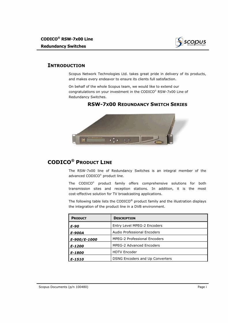
RSW-7X00 REDUNDANCY SWITCH SERIES
CODICO® PRODUCT LINE The RSW-7x00 line of Redundancy Switches is an integral member of the
advanced CODICO product line.
The CODICO product family offers comprehensive solutions for both
transmission sites and reception stations. In addition, it is the most
cost-effective solution for TV broadcasting applications.
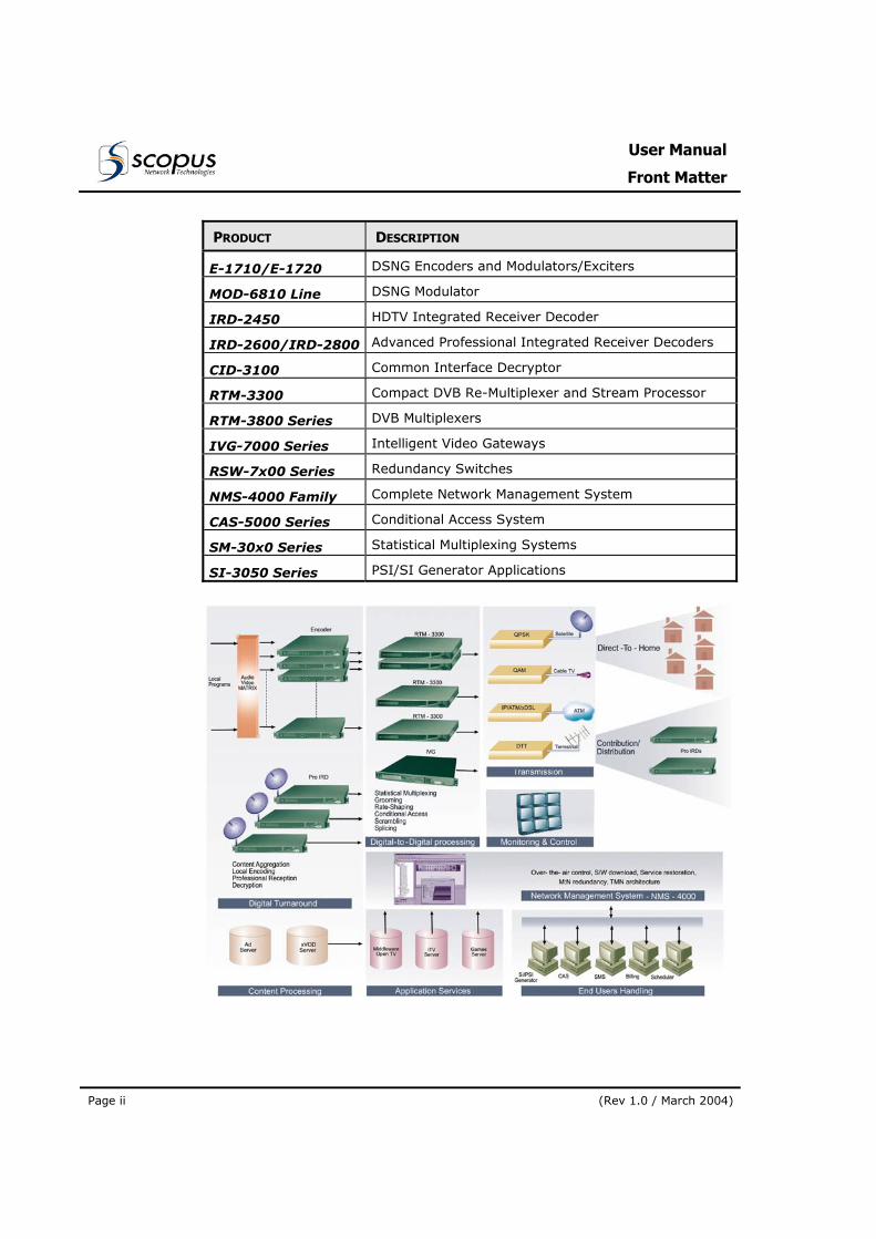
The following table lists the CODICO® product family and the illustration displays
the integration of the product line in a DVB environment.
PRODUCT DESCRIPTION
E-90 Entry Level MPEG-2 Encoders
E-900A Audio Professional Encoders
E-900/E-1000 MPEG-2 Professional Encoders
E-1200 MPEG-2 Advanced Encoders
E-1800 HDTV Encoder
E-1510 DSNG Encoders and Up Converters
User Manual
Front Matter
Page ii (Rev 1.0 / March 2004)
PRODUCT DESCRIPTION
E-1710/E-1720 DSNG Encoders and Modulators/Exciters
MOD-6810 Line DSNG Modulator
IRD-2450 HDTV Integrated Receiver Decoder
IRD-2600/IRD-2800 Advanced Professional Integrated Receiver Decoders
CID-3100 Common Interface Decryptor
RTM-3300 Compact DVB Re-Multiplexer and Stream Processor
RTM-3800 Series DVB Multiplexers
IVG-7000 Series Intelligent Video Gateways
RSW-7x00 Series Redundancy Switches
NMS-4000 Family Complete Network Management System
CAS-5000 Series Conditional Access System
SM-30x0 Series Statistical Multiplexing Systems
SI-3050 Series PSI/SI Generator Applications
CODICO® RSW-7x00 Line
Redundancy Switches
Scopus Documents (p/n 100480) Page iii
MANUAL SCOPE AND STRUCTURE The User Manual for the CODICO® RSW-7x00 Line of Redundancy Switches is
comprised of three main sections:
1. OVERVIEW:
This section provides introduction and product, including highlights, benefits and typical applications, offers a functional and physical description of the unit and lists its main capabilities and specifications.
2. INSTALLATION:
This section provides data and procedures required to install and activate the unit.
3. OPERATION:
This section provides theoretical background on the unit operation and details data and instructions on using the unit and operating the control and monitoring functions.
A Connectors and Cables Appendix is also provided with technical data on
the connectors provided on the R-Switches and the special cables required for
connecting the R-Switch.
It is assumed throughout this document that personnel have a general
knowledge of RSW-7x00 R-Switches Line, its application, and capabilities.
General knowledge of the CODICO® System and its application is also assumed.
For detailed information, refer to the CODICO® MPEG-2 DVB Product Family
Description documentation.
User Manual
Front Matter
Page iv (Rev 1.0 / March 2004)
TECHNICAL SUPPORT In case of technical problems with the CODICO system or one of its
components please refer to the System Documentation. Usually, this will save
you time in resolving technical difficulties.
If you are not able to resolve the problem call your local distributor for technical
support.
HOW TO RETURN FAULTY PARTS
Before Returning An Item: • Request an RMA (Return Merchandise Authorisation) Tracking Number
from your local distributor.
• Scopus Network Technologies Support will assign an RMA Tracking Number; this must accompany the item being returned and will be referred to in all correspondence.
• Send the item to Scopus Network Technologies with the RMA Tracking Number included in the accompanying documentation (shipping and customs forms).
Customer Support Point Of Contact (POC) Scopus Network Technologies Inc.
U.S. Offices
Scopus Network Technologies Ltd.
International Headquarters
100 Overlook Center Drive, 3rd Floor
Princeton, NJ 08540. USA
10 Ha’amal St., Park Afek
Rosh Ha’ayin, 48092 Israel
Tel: (609)-987-8090 Fax: (609)-987-8095
Tel: (972) –3-900-7777 Fax: (972) –3-900-7888
Email: [email protected]
Web: www.scopus.net
CODICO® RSW-7x00 Line
Redundancy Switches
Scopus Documents (p/n 100480) Page v
Warranty SCOPUS Network Technologies Ltd. warrants that the Product and any part thereof, including, but not limited to spare parts, will, when properly installed, conform to SCOPUS Network Technologies Ltd. published specifications and that the Product and any parts thereof, including, but not limited to, spare parts, will be free from defects deriving from wrong workmanship and faulty materials under normal use and service, for a period of twelve (12) months following the date of manufacture thereof.
The supply of spare parts at reasonable cost shall be available for a period of three (3) years from the date of delivery.
This warranty does not cover ordinary wear and tear of the Product or other defects due to circumstances beyond SCOPUS Network Technologies Ltd. control such as unsuitable operating means, chemical, Electro-mechanical or electrical influences and damages which may be caused by interference by the CUSTOMER or any unauthorized third party.
Defective cards/assemblies will be sent to SCOPUS Network Technologies Ltd. for repair. The repaired cards/assemblies will be returned to the CUSTOMER within 30 days from their receipt by SCOPUS Network Technologies Ltd.
Cards/assemblies repaired during the 12 months warranty period will carry a warranty of 6 months from date of repair or until end of original warranty period, whichever is the later date.
SCOPUS Network Technologies Ltd. sole liability under this warranty shall be limited to the repair or replacement with equivalent units at SCOPUS Network Technologies Ltd. facilities, of any Product or parts thereof that do not conform to SCOPUS Network Technologies Ltd. published specifications or that are defective in material or workmanship, as specified above. The expense of installing repaired or replaced parts shall be borne by the CUSTOMER.
SCOPUS Network Technologies Ltd. sole obligation under this Warranty is be the supplier of the Product to the CUSTOMER and to provide such services as set out in this Warranty on the SCOPUS Network Technologies Ltd. terms and conditions provided for herein. In no event will SCOPUS Network Technologies Ltd. be liable to the CUSTOMER for any business expenses, loss of profits, incidental, indirect or consequential damages, however caused, unless such expenses, loss or damages shall have derived from an infringement of patents of copyrights.
THE WARRANTIES STATED HEREIN ARE EXCLUSIVE AND ARE EXPRESSLY IN LIEU OF ALL OTHER WARRANTIES, EXPRESSED OR IMPLIED, INCLUDING, BUT NOT LIMITED TO, THE IMPLIED WARRANTY OF MERCHANTABILITY OR FITNESS FOR A PARTICULAR PURPOSE.
Beyond the warranty period, SCOPUS Network Technologies Ltd. shall repair or replace defective cards/assemblies according to its standard price list relevant at such time. Cards/assemblies thus repaired shall carry a warranty of 6 months.
User Manual
Front Matter
Page vi (Rev 1.0 / March 2004)
TABLE OF CONTENTS
Section 1.Overview............................................................................. 1-1 1.1. Introduction ...................................................................................................... 1-1
1.1.1. Highlights and Benefits .................................................................... 1-2 1.1.2. The RSW-7x00 Line Members ........................................................... 1-3
1.2. Applications....................................................................................................... 1-4 1.2.1. 1+1 IRD Redundancy Application ...................................................... 1-4 1.2.2. 1+1 Encoder Redundancy Application ................................................ 1-6 1.2.3. MCPC Distribution Redundancy Application ......................................... 1-7 1.2.4. 1+1 DSNG Contribution Redundancy Application................................. 1-8 1.2.5. Optical MCPC Multiplexing Redundancy Application.............................. 1-9
1.3. Architecture and Operating Mode ................................................................. 1-10 1.3.1. Stand-Alone Redundancy Management ............................................ 1-10 1.3.2. Network Redundancy Management.................................................. 1-10
1.4. Mechanical Structure...................................................................................... 1-11 1.4.1. Housing ....................................................................................... 1-11 1.4.2. Front Panel .................................................................................. 1-11 1.4.3. Rear Panel ................................................................................... 1-12
1.5. Capabilities and Specifications ...................................................................... 1-13 1.5.1. Capabilities and In/Out Interfaces ................................................... 1-13 1.5.2. Electrical Requirements ................................................................. 1-15 1.5.3. Physical Characteristics.................................................................. 1-15
Section 2.Installation ......................................................................... 2-1 2.1. General.............................................................................................................. 2-1 2.2. Installation Information ................................................................................... 2-1
2.2.1. Safety Precautions .......................................................................... 2-1 2.2.2. Inventory Check ............................................................................. 2-1
2.3. Mechanical Installation..................................................................................... 2-2 2.3.1. Site Preparation Guidelines .............................................................. 2-2 2.3.2. Rack Mounting................................................................................ 2-2
2.4. Electrical Installation........................................................................................ 2-3 2.4.1. Power and Ground Connection.......................................................... 2-3 2.4.2. Interconnecting Cabling Installation .................................................. 2-4
Section 3.R-Switch Operation........................................................... 3-1 3.1. General.............................................................................................................. 3-1 3.2. R-Switch Front Panel Operation ...................................................................... 3-1
3.2.1. Front Panel Operation Principles........................................................ 3-1
CODICO® RSW-7x00 Line
Redundancy Switches
Scopus Documents (p/n 100480) Page vii
3.2.2. Front Panel Operation Concept ......................................................... 3-3 3.2.3. Front Panel Operation Procedure....................................................... 3-4
3.3. R-Switch Command Protocol ...........................................................................3-6 Appendix A. Connectors and Cables ...................................................... 1
A.1 RSW-7000 Connector and Cables Data .............................................................1 A.2 RSW-7200 Connectors and Cables Data............................................................5
LIST OF FIGURES Figure 1-1: RSW-7x00 Redundancy Switch Series - General View.................................1-1 Figure 1-2: Automatic IRD Switching and 1+1 Redundancy Layout Diagram.................1-5 Figure 1-3: Automatic Encoders Switching, 1+1 Redundancy Layout Diagram...............1-6 Figure 1-4: MCPC Distribution Application, Redundancy Layout Diagram.......................1-7 Figure 1-5: DSNG Contribution Application, 1+1 Redundancy Layout Diagram ..............1-8 Figure 1-6: Optical MCPC Multiplexing Redundancy - Layout Diagram...........................1-9 Figure 1-7: RSW-7x00 R-Switch Line Front Panel ......................................................1-11 Figure 1-8: RSW-7x00 R-Switch Line - Rear Panel Configurations...............................1-12 Figure 2-1: Decoder Redundancy Switching Cabling ....................................................2-4 Figure 2-2: Encoder #0 and #1 - ASI Switching Redundancy Cabling ...........................2-6 Figure 2-3: Cabling for Multiplexers Redundancy Switch ..............................................2-8 Figure 3-1: Encoder R-Switch Front Panel...................................................................3-1
LIST OF TABLES Table 1-1: RSW-7x00 R-Switch Line - Input / Output Interfaces................................1-13 Table 1-2: RSW-7x00 Redundancy Switch - Electrical Requirements..........................1-15 Table 1-3: RSW-7x00 R-Switch Line - Mechanical Dimensions..................................1-15 Table 1-4: RSW-7x00 R-Switch Line Environmental Conditions..................................1-16 Table 2-1: 1+1 Decoder Redundancy Switch Connections ..........................................2-5 Table 2-2: 1+1 Encoder Redundancy Switch Connections...........................................2-7 Table 2-3: 1+1 Multiplexer Redundancy Switch Connections.......................................2-9 Table 3-1: R-Switch Command Protocol.....................................................................3-6 Table A-1: RSW-7000 CONTROL (A & B) Connector (9 Pin D-Type, Male) .......................1 Table A-2: DATA Connector (9 Pin D-Type, Male)..........................................................1 Table A-3: Data / Control A & B Connector (9 Pin D-Type, Male)....................................2 Table A-4: AUXILIARY A & B Connector (25 Pin D-Type, Male) ......................................2 Table A-5: Auxiliary Cable, Pin-to-Pin Description ..........................................................3 Table A-6: Data and Control Cable, Pin-to-Pin Connection .............................................4 Table A-7: RSW-7200 Control Connector (9 Pin D-Type, Male).......................................5 Table A-8: AUXILIARY A & B Connector (25 Pin D-Type, Male) ......................................5
User Manual
Front Matter
Page viii (Rev 1.0 / March 2004)
Table A-9: HSD and LSD Input A and B Connector (9 Pin D-Type, Male)........................ 6 Table A-10: LSD Output and GPI Output Connector (9 Pin D-Type, Male) ........................ 6 Table A-11: HSD Output Connector (9 Pin D-Type, Male) ............................................... 7 Table A-12: RSW-7200 Auxiliary to Encoder Cable, Pin Out Designations ......................... 8 Table A-13: HSD and LSD Input to Encoder Cable, Pin Out Designations ......................... 9 Table A-14: RSW-7200 Control to NMS-4000 Cable, Pin Out Designations.......................10
CODICO® RSW-7x00 Line
Redundancy Switches
Scopus Documents (p/n 100480) Page 1-1
Section 1. OVERVIEW
1.1. INTRODUCTION
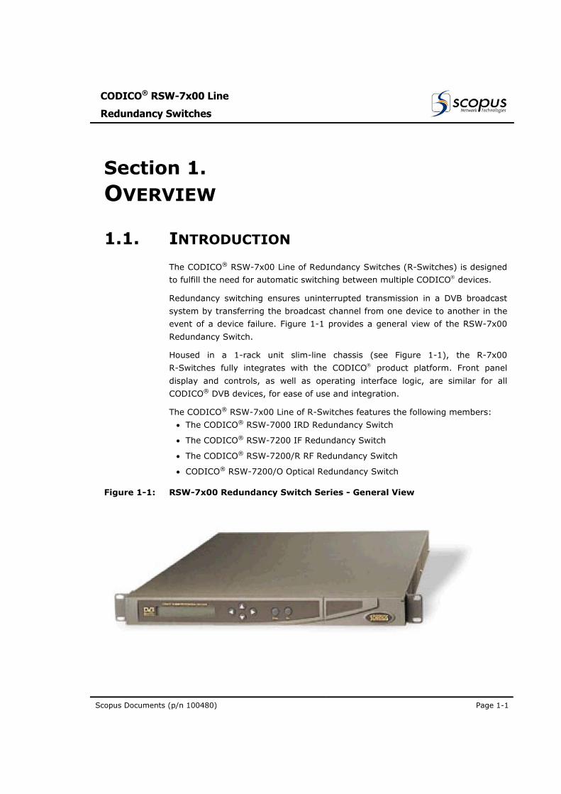
The CODICO® RSW-7x00 Line of Redundancy Switches (R-Switches) is designed
to fulfill the need for automatic switching between multiple CODICO devices.
Redundancy switching ensures uninterrupted transmission in a DVB broadcast
system by transferring the broadcast channel from one device to another in the
event of a device failure. Figure 1-1 provides a general view of the RSW-7x00
Redundancy Switch.
Housed in a 1-rack unit slim-line chassis (see Figure 1-1), the R-7x00
R-Switches fully integrates with the CODICO product platform. Front panel
display and controls, as well as operating interface logic, are similar for all
CODICO® DVB devices, for ease of use and integration.
The CODICO® RSW-7x00 Line of R-Switches features the following members:
• The CODICO® RSW-7000 IRD Redundancy Switch
• The CODICO® RSW-7200 IF Redundancy Switch
• The CODICO® RSW-7200/R RF Redundancy Switch
• CODICO® RSW-7200/O Optical Redundancy Switch
Figure 1-1: RSW-7x00 Redundancy Switch Series - General View
User Manual
Overview
Page 1-2 (Rev 1.0 / March 2004)
1.1.1. Highlights and Benefits The RSW-7x00 Line of Redundancy Switches features the following highlights
and benefits:
MULTIPLE CONTROL OPTIONS Locally controlled applications, using the R-Switch Front Panel (locally)
Stand alone applications, using the GPI dry contact relay
Remote controlled applications, using the RS-232 interfaces
Network applications, remotely controlled by NMS-4000
UNINTERRUPTED TRANSMISSION The RSW-7x00 Line provides full redundancy switching to facilitate uninterrupted transmission.
STAND-ALONE AND NETWORK REDUNDANCY SWITCHING The RSW-7000 R-Switch is suitable for GPI controlled stand-alone applications only.
The three RSW-7200 R-Switch versions are configured for either GPI controlled stand-alone applications or for network applications, remotely controlled by the CODICO® NMS-4000 Network Management System.
NETWORK REDUNDANCY MANAGEMENT The RSW-7200 group of R-Switches provides automatic remote switching between devices installed in DVB networks:
ASI level transport streams, using the RSW-7200 R-Switch
RF modulated TS, using the RSW-7200/R R-Switch
Optical TS, using the RSW-7200/O R-Switch
MULTIPLE MODES OF OPERATION The R-Switch offers multiple switching modes:
Remote Switching, via the NMS-4000 (available at the RSW-7200 group)
Manual Mode, for manual switching between channels
Automatic Mode (default mode), for automatic redundancy switching
USER FRIENDLY CONTROLS The R-Switch Front Panel provides a management menu tree. An LCD display, a four-way ( [(Left] / [Right] / [Up] / [Down]) touch pad, as well as [Enter] and [Esc] keys are provided on the Front Panel to facilitate user access to the parameters in the menus.
CODICO® RSW-7x00 Line
Redundancy Switches
Scopus Documents (p/n 100480) Page 1-3
1.1.2. The RSW-7x00 Line Members The RSW-7X00 Line consists of the following Redundancy Switches:
CODICO® RSW-7000 IRD REDUNDANCY SWITCH Provides GPI controlled, stand-alone redundancy solutions for 1+1 IRDs
CODICO® RSW-7200 IF REDUNDANCY SWITCH Provides IF level transport stream redundancy switching in encoders and multiplexers. It can also provide high-bandwidth ASI or IF signals and Audio, Data and ASI switching for stand alone 1+1 Encoders.
Finally, the RSW-7200 can provide stand-alone 1+1 redundancy switching for any GPI-enabled CODICO® Device (Encoders, Multiplexers, CIDs and Modulators).
The RSW-7200 can be used for redundancy control in an application controlled by Network Management Systems (such as the CODICO® NMS-4000).
CODICO® RSW-7200/R RF REDUNDANCY SWITCH Provides redundancy switching between two RF modulated signals in the bandwidth range of 950 through 18,400 MHz. These signals are and generated by two Up-Converters, integrated with DSNG Encoders and Modulators.
The RSW-7200/R can be applied for NMS-4000 controlled redundancy applications or as a GPI controlled stand-alone redundancy applications.
CODICO® RSW-7200/O OPTICAL REDUNDANCY SWITCH Provides transport stream redundancy switching of optical ASI or STM-1/OC3 signals for 1+1 encoders, multiplexers or modulators redundancy applications.
The RSW-7200/R can be applied for NMS-4000 controlled redundancy applications or as a GPI controlled stand-alone redundancy applications.
User Manual
Overview
Page 1-4 (Rev 1.0 / March 2004)
1.2. APPLICATIONS
The RSW-7x00 R-Switch Line of Redundancy Switches may be employed within
a DVB broadcast system for a dependable, uninterrupted signal flow in a wide
range of redundancy management applications:
• RSW-7000, in a stand-alone 1+1 IRD redundancy application
• RSW-7200, in a stand-alone 1+1 Encoder redundancy application
• RSW-7200, in a NMS-4000 controlled Multiplexers redundancy application
• RSW-7200/R, in a stand-alone 1+1 DSNG redundancy application
• RSW-7200/O, in a stand-alone 1+1 MCPC redundancy application.
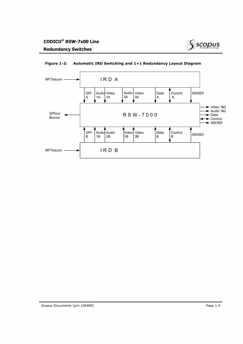
1.2.1. 1+1 IRD Redundancy Application The CODICO® RSW-7000 Redundancy Switch is a “Hot Switch Over”, without
effecting the service, featuring configurable switching time. Figure 1-2 illustrates
an RSW-7000 R-Switch controlling a 1+1 IRD Redundancy Transport Stream
Output application.
At power-up, the R-Switch monitors the GPI Status from both IRDs, selecting
the IRD-A (default) as the Active device output.
Should a failure be detected in the active IRD-A, the RSW-7000 receives a
failure status report over the GPI Dry Contacts and sends a switching command
(over GPI) to the IRDs. The IRD-A outputs are disconnected and the IRD-B
device is selected as the Active device. An alarm is activated that can be
manually reset when the fault is corrected and IRD-A is ready for operation.
However, switching to IRD-A will be done only when a failure is detected in the
currently Active IRD (meaning IRD-B).
The GPI command can be pre-set in the IRD for several alarm conditions. The
user can reconfigure the IRD, according to his specific requirements.
CODICO® RSW-7x00 Line
Redundancy Switches
Scopus Documents (p/n 100480) Page 1-5
Figure 1-2: Automatic IRD Switching and 1+1 Redundancy Layout Diagram
I R D A
I R D B
R S W - 7 0 0 0
Audio1A
ASI/SDIControlB
DataB
Video2B
Video1B
Audio1B
ASI/SDIControlA
DataA
Video2A
Video1A
GPIB
GPIA
RF/Telcom
GPIoutBuzzer
RF/Telcom
ASI/SDIControlDataAudio 1&2Video 1&2
Audio2A
Audio2B
User Manual
Overview
Page 1-6 (Rev 1.0 / March 2004)
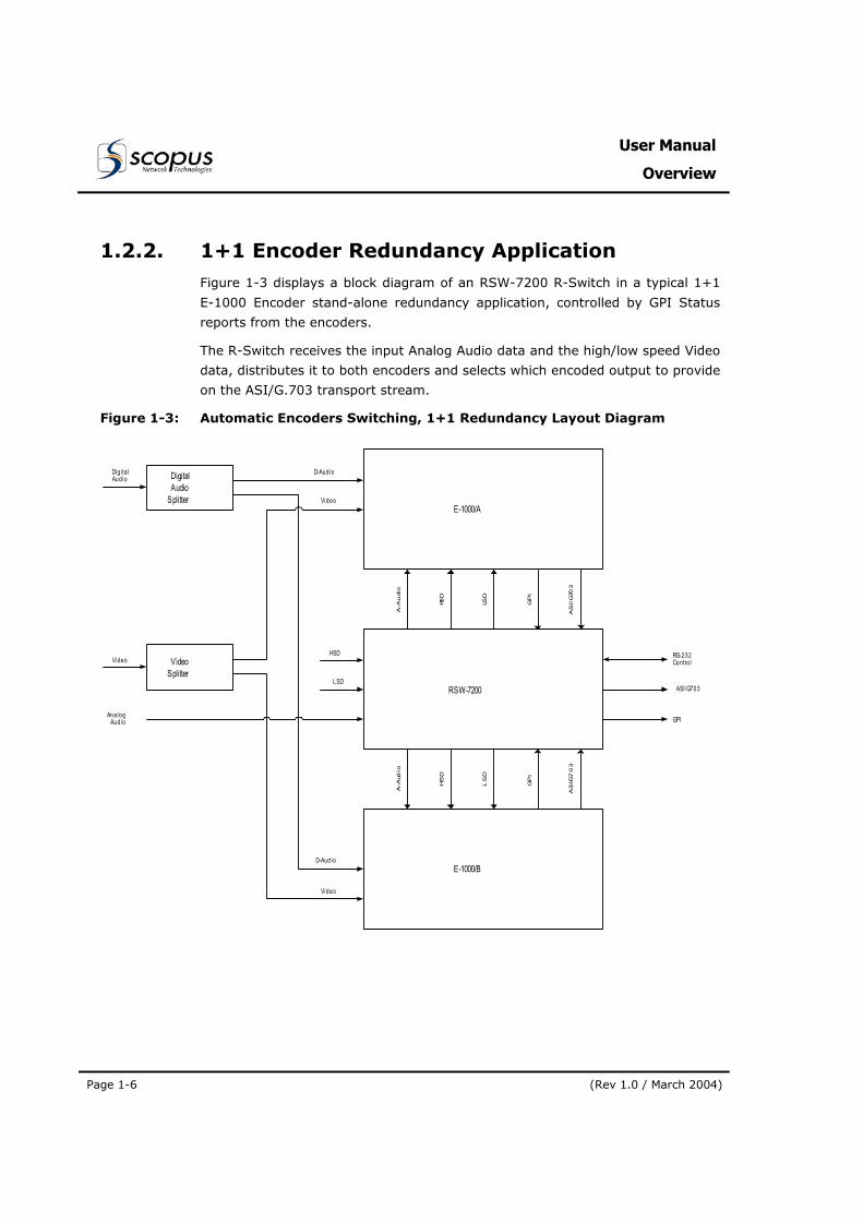
1.2.2. 1+1 Encoder Redundancy Application Figure 1-3 displays a block diagram of an RSW-7200 R-Switch in a typical 1+1
E-1000 Encoder stand-alone redundancy application, controlled by GPI Status
reports from the encoders.
The R-Switch receives the input Analog Audio data and the high/low speed Video
data, distributes it to both encoders and selects which encoded output to provide
on the ASI/G.703 transport stream.
Figure 1-3: Automatic Encoders Switching, 1+1 Redundancy Layout Diagram
DigitalAudio
Splitter
VideoSplitter
E-1000/A
RSW-7200
A-A
udi
o
HSD
LSD
AS
I/G
703
E-1000/B
A-A
udio
HS
D
LS
D
AS
I/G7
03
D-Aud io
D-Audio
Video
Video
AnalogAudio
Video
GPI
ASI/G703
RS-232Contro l
LSD
HSD
Digi ta lAud io
GP
IG
PI
CODICO® RSW-7x00 Line
Redundancy Switches
Scopus Documents (p/n 100480) Page 1-7
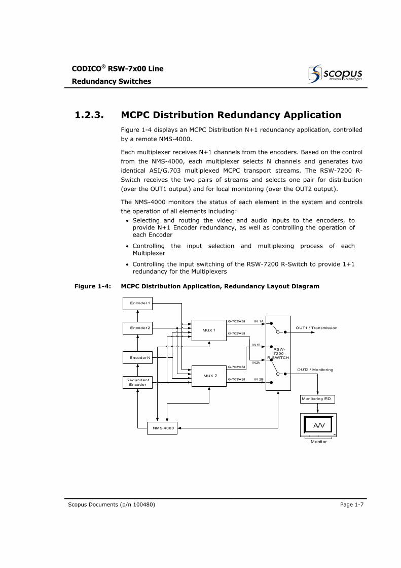
1.2.3. MCPC Distribution Redundancy Application Figure 1-4 displays an MCPC Distribution N+1 redundancy application, controlled
by a remote NMS-4000.
Each multiplexer receives N+1 channels from the encoders. Based on the control
from the NMS-4000, each multiplexer selects N channels and generates two
identical ASI/G.703 multiplexed MCPC transport streams. The RSW-7200 R-
Switch receives the two pairs of streams and selects one pair for distribution
(over the OUT1 output) and for local monitoring (over the OUT2 output).
The NMS-4000 monitors the status of each element in the system and controls
the operation of all elements including:
• Selecting and routing the video and audio inputs to the encoders, to provide N+1 Encoder redundancy, as well as controlling the operation of each Encoder
• Controlling the input selection and multiplexing process of each Multiplexer
• Controlling the input switching of the RSW-7200 R-Switch to provide 1+1 redundancy for the Multiplexers
Figure 1-4: MCPC Distribution Application, Redundancy Layout Diagram
Encoder 1
Encoder 2
Encoder N
RedundantEncoder
NMS-4000
MUX A
MUX B
RSW-7200
R-SWITCH
Monitoring IRD
G-703/ASI
G-703/ASI
G-703/ASI
G-703/ASI IN 1A
IN 2A
IN 1B
IN 2B
OUT1 / Transmission
OUT2 / Monitoring
Monitor
A/V
IN 1B
IN2A
1
2
User Manual
Overview
Page 1-8 (Rev 1.0 / March 2004)
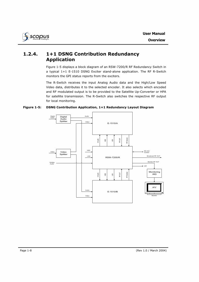
1.2.4. 1+1 DSNG Contribution Redundancy Application Figure 1-5 displays a block diagram of an RSW-7200/R RF Redundancy Switch in
a typical 1+1 E-1510 DSNG Exciter stand-alone application. The RF R-Switch
monitors the GPI status reports from the exciters.
The R-Switch receives the input Analog Audio data and the High/Low Speed
Video data, distributes it to the selected encoder. It also selects which encoded
and RF modulated output is to be provided to the Satellite Up-Converter or HPA
for satellite transmission. The R-Switch also switches the respective RF output
for local monitoring.
Figure 1-5: DSNG Contribution Application, 1+1 Redundancy Layout Diagram
DigitalAudioSplitter
VideoSplitter
E-1510/A
RSW-7200/R
A-Au
dio
HSD
LSD
RF M
onito
r
E-1510/B
A-Au
dio
HSD
LSD
RF M
onito
r
Audio
Audio
Video
Video
AnalogAudio
Video
Monitor RF OUT
Broadcast RF OUT
RS-232Control
LSD
HSD
DigitalAudio
RF O
UTRF
OUT
GPI
MonitoringIRD
Monitor
A/V
CODICO® RSW-7x00 Line
Redundancy Switches
Scopus Documents (p/n 100480) Page 1-9
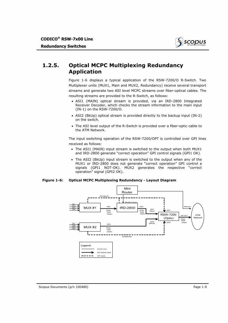
1.2.5. Optical MCPC Multiplexing Redundancy Application Figure 1-6 displays a typical application of the RSW-7200/O R-Switch. Two
Multiplexer units (MUX1, Main and MUX2, Redundancy) receive several transport
streams and generate two ASI level MCPC streams over fiber-optical cables. The
resulting streams are provided to the R-Switch, as follows:
• ASI1 (MAIN) optical stream is provided, via an IRD-2800 Integrated Receiver Decoder, which checks the stream information to the main input (IN-1) on the RSW-7200/O.
• ASI2 (BkUp) optical stream is provided directly to the backup input (IN-2) on the switch.
• The ASI level output of the R-Switch is provided over a fiber-optic cable to the ATM Network.
The input switching operation of the RSW-7200/OPT is controlled over GPI lines
received as follows:
• The ASI1 (MAIN) input stream is switched to the output when both MUX1 and IRD-2800 generate “correct operation” GPI control signals (GPI1 OK).
• The ASI2 (BkUp) input stream is switched to the output when any of the MUX1 or IRD-2800 does not generate “correct operation” GPI control a signals (GPI1 NOT-OK). MUX2 generates the respective “correct operation” signal (GPI2 OK).
Figure 1-6: Optical MCPC Multiplexing Redundancy - Layout Diagram
MUX #1 IRD-2800
MUX #2
TS1TS2TS3TS4
TS1TS2TS3TS4
RSW-7200(Optic)
ATM Network
MiniRouter
ASI1(Main)(Fiber
OpticCable)
(FiberOpticCable)
ASI2(BKUP)
ASI1 ASI1
ASI2
(FiberOpticCable)
(FiberOpticCable)
ASI OUT
Ethernet
RS-232 Control
GPI1(MUX1)
GPI2(MUX2)
GPI1
GPI2
Legend:Control Line
ASI Optical Cable
GPI Cable
User Manual
Overview
Page 1-10 (Rev 1.0 / March 2004)
1.3. ARCHITECTURE AND OPERATING MODE
The R-Switch line provides for stand-alone redundancy management applications
as well as for network managed applications.
The following sub-paragraphs describe the architecture of a typical redundancy
system and describe the operating mode of the redundancy application, for
either stand-alone systems as well as for remotely managed systems
1.3.1. Stand-Alone Redundancy Management In a stand-alone configuration, the R-Switch receives inputs from two devices
and provides one output for broadcast. One device (Device A by default) is set
as “Active”, and the second device (Device B) is set as “Standby”.
The R-Switch performs continual checks on the status reports provided on the
GPI Dry Contacts of both devices, determining their state of operation over time.
Upon signal failure or malfunction in Device A, the R-Switch changes Device B to
be the “Active” device with little or no interruption in the transmission.
Switching between the devices activates an alarm that can be manually de-
activated when the failure is corrected.
Once the R-Switch has determined that the recovered device has stabilized, the
status indicator for Device A will display “OK” instead of “FAIL”.
Yet, returning Device A to “OK” status does not return Device A to the status of
“Active”. The switched status (Device B as “Active” and Device A as
“Standby”) is kept until a failure is detected in the currently active device
(Device B) and then the R-Switch switches again between the devices.
1.3.2. Network Redundancy Management
When the R-Switch is remotely controlled by the NMS-4000 Network
Management System, the NMS monitors and controls the operation of all
elements in the system and redundancy switching is activated by the NMS when
required.
CODICO® RSW-7x00 Line
Redundancy Switches
Scopus Documents (p/n 100480) Page 1-11
1.4. MECHANICAL STRUCTURE
1.4.1. Housing The RSW-7x00 Line of R-Switches are housed in a ruggedized industrial
enclosure, 1 U by 19" (Rack Mount). The unified enclosure allows for easy
installation and integration into a new or pre-existing system.
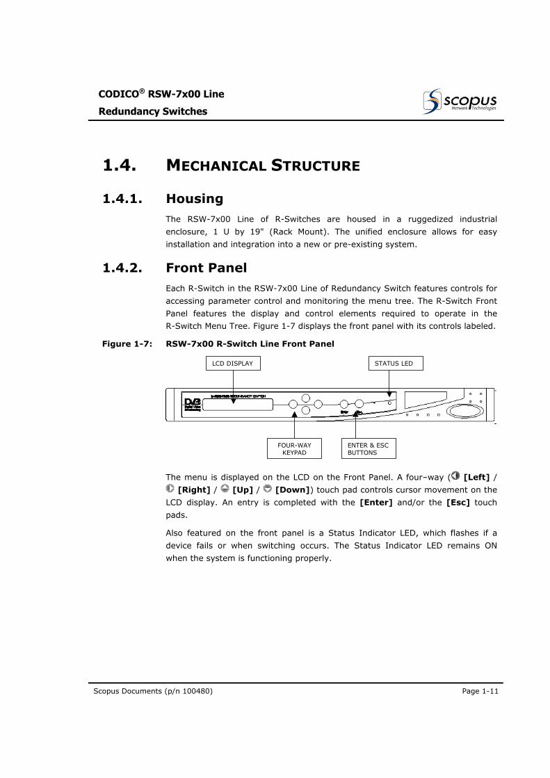
1.4.2. Front Panel Each R-Switch in the RSW-7x00 Line of Redundancy Switch features controls for
accessing parameter control and monitoring the menu tree. The R-Switch Front
Panel features the display and control elements required to operate in the
R-Switch Menu Tree. Figure 1-7 displays the front panel with its controls labeled.
Figure 1-7: RSW-7x00 R-Switch Line Front Panel
LCD DISPLAY
FOUR-WAY KEYPAD
ENTER & ESC BUTTONS
STATUS LED
The menu is displayed on the LCD on the Front Panel. A four–way ( [Left] /
[Right] / [Up] / [Down]) touch pad controls cursor movement on the
LCD display. An entry is completed with the [Enter] and/or the [Esc] touch
pads.
Also featured on the front panel is a Status Indicator LED, which flashes if a
device fails or when switching occurs. The Status Indicator LED remains ON
when the system is functioning properly.
User Manual
Overview
Page 1-12 (Rev 1.0 / March 2004)
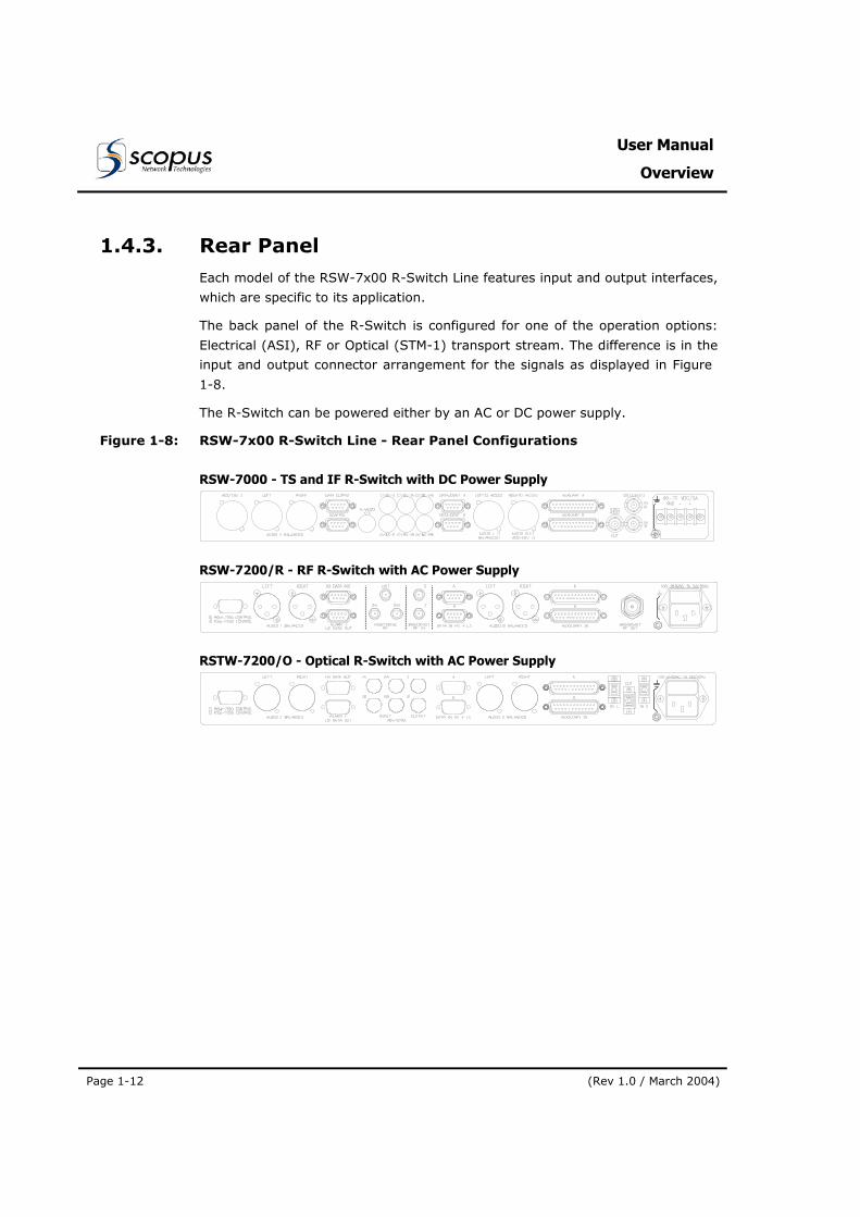
1.4.3. Rear Panel Each model of the RSW-7x00 R-Switch Line features input and output interfaces,
which are specific to its application.
The back panel of the R-Switch is configured for one of the operation options:
Electrical (ASI), RF or Optical (STM-1) transport stream. The difference is in the
input and output connector arrangement for the signals as displayed in Figure 1-8.
The R-Switch can be powered either by an AC or DC power supply.
Figure 1-8: RSW-7x00 R-Switch Line - Rear Panel Configurations
RSW-7000 - TS and IF R-Switch with DC Power Supply
RSW-7200/R - RF R-Switch with AC Power Supply
RSTW-7200/O - Optical R-Switch with AC Power Supply
CODICO® RSW-7x00 Line
Redundancy Switches
Scopus Documents (p/n 100480) Page 1-13
1.5. CAPABILITIES AND SPECIFICATIONS
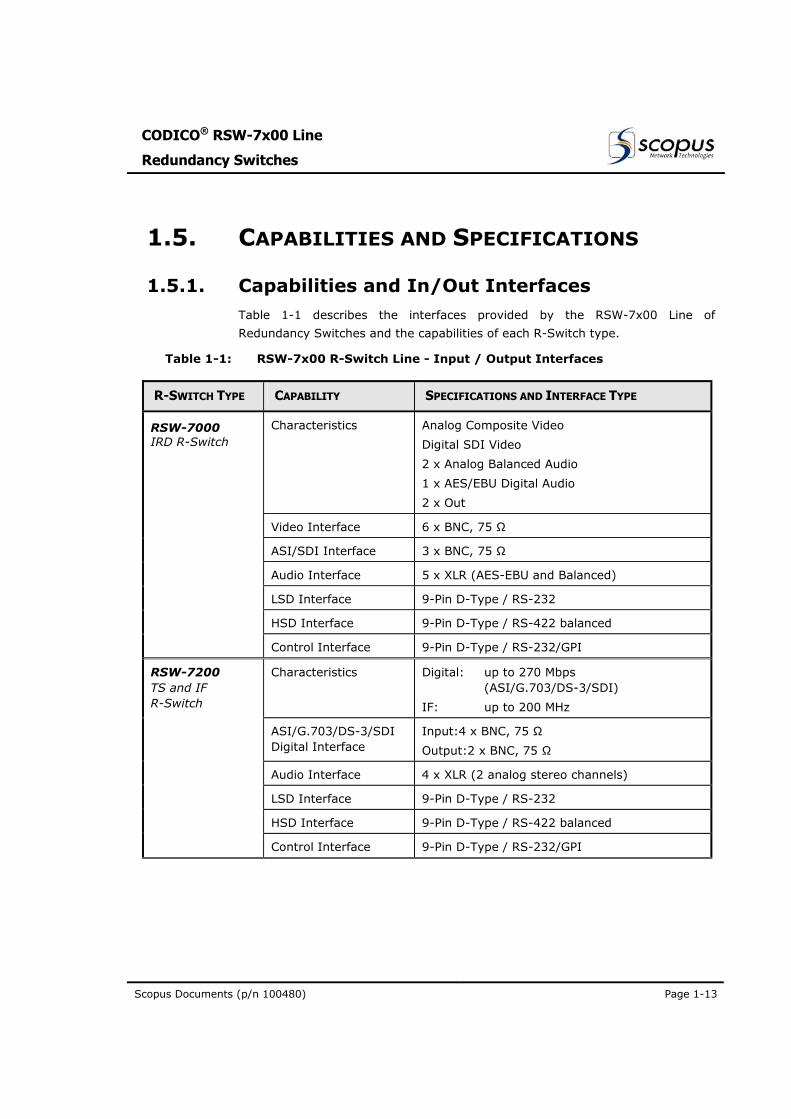
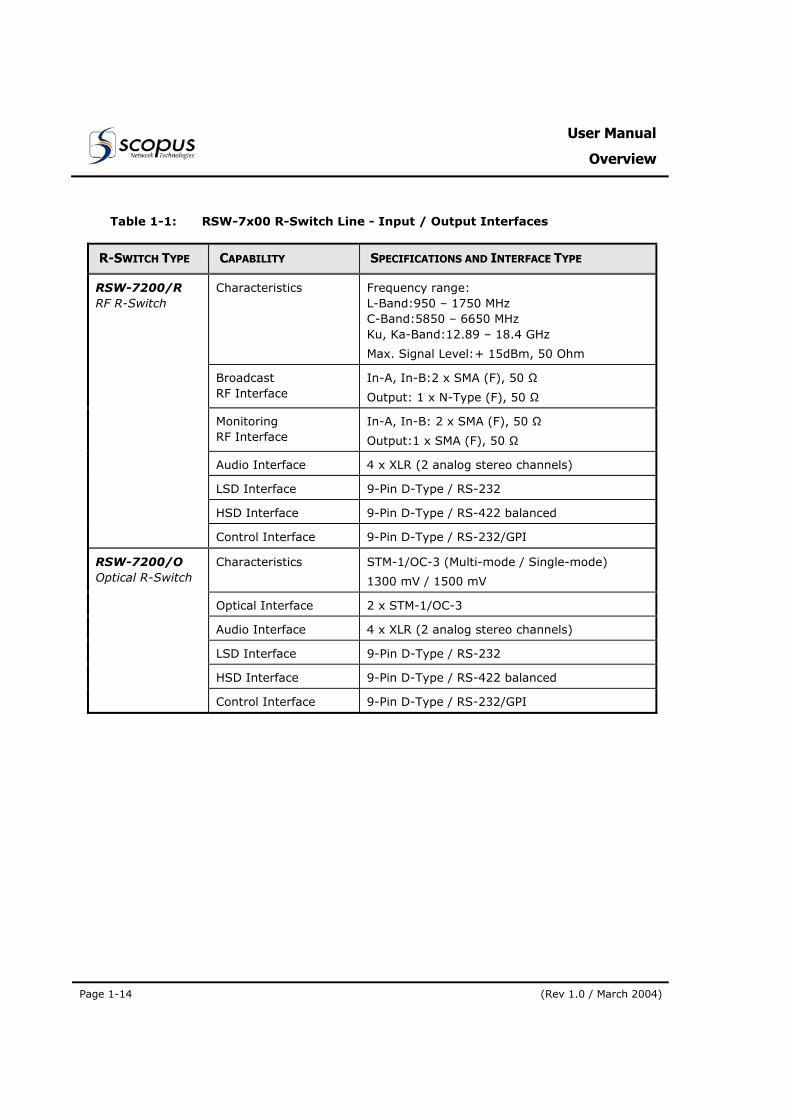
1.5.1. Capabilities and In/Out Interfaces Table 1-1 describes the interfaces provided by the RSW-7x00 Line of
Redundancy Switches and the capabilities of each R-Switch type.
Table 1-1: RSW-7x00 R-Switch Line - Input / Output Interfaces
R-SWITCH TYPE CAPABILITY SPECIFICATIONS AND INTERFACE TYPE
Characteristics Analog Composite Video
Digital SDI Video
2 x Analog Balanced Audio
1 x AES/EBU Digital Audio
2 x Out
Video Interface 6 x BNC, 75 Ω
ASI/SDI Interface 3 x BNC, 75 Ω
Audio Interface 5 x XLR (AES-EBU and Balanced)
LSD Interface 9-Pin D-Type / RS-232
HSD Interface 9-Pin D-Type / RS-422 balanced
RSW-7000 IRD R-Switch
Control Interface 9-Pin D-Type / RS-232/GPI
Characteristics Digital: up to 270 Mbps (ASI/G.703/DS-3/SDI)
IF: up to 200 MHz
ASI/G.703/DS-3/SDI Digital Interface
Input:4 x BNC, 75 Ω
Output:2 x BNC, 75 Ω
Audio Interface 4 x XLR (2 analog stereo channels)
LSD Interface 9-Pin D-Type / RS-232
HSD Interface 9-Pin D-Type / RS-422 balanced
RSW-7200 TS and IF R-Switch
Control Interface 9-Pin D-Type / RS-232/GPI
User Manual
Overview
Page 1-14 (Rev 1.0 / March 2004)
Table 1-1: RSW-7x00 R-Switch Line - Input / Output Interfaces
R-SWITCH TYPE CAPABILITY SPECIFICATIONS AND INTERFACE TYPE
Characteristics Frequency range: L-Band:950 – 1750 MHz C-Band:5850 – 6650 MHz Ku, Ka-Band:12.89 – 18.4 GHz
Max. Signal Level: + 15dBm, 50 Ohm
Broadcast RF Interface
In-A, In-B: 2 x SMA (F), 50 Ω
Output: 1 x N-Type (F), 50 Ω
Monitoring RF Interface
In-A, In-B: 2 x SMA (F), 50 Ω
Output:1 x SMA (F), 50 Ω
Audio Interface 4 x XLR (2 analog stereo channels)
LSD Interface 9-Pin D-Type / RS-232
HSD Interface 9-Pin D-Type / RS-422 balanced
RSW-7200/R RF R-Switch
Control Interface 9-Pin D-Type / RS-232/GPI
Characteristics STM-1/OC-3 (Multi-mode / Single-mode)
1300 mV / 1500 mV
Optical Interface 2 x STM-1/OC-3
Audio Interface 4 x XLR (2 analog stereo channels)
LSD Interface 9-Pin D-Type / RS-232
HSD Interface 9-Pin D-Type / RS-422 balanced
RSW-7200/O Optical R-Switch
Control Interface 9-Pin D-Type / RS-232/GPI
CODICO® RSW-7x00 Line
Redundancy Switches
Scopus Documents (p/n 100480) Page 1-15
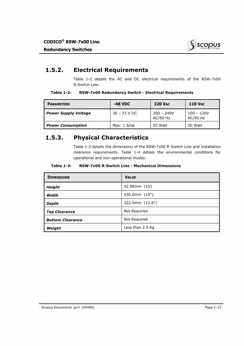
1.5.2. Electrical Requirements Table 1-2 details the AC and DC electrical requirements of the RSW-7x00
R-Switch Line.
Table 1-2: RSW-7x00 Redundancy Switch - Electrical Requirements
PARAMETERS -48 VDC 220 VAC 110 VAC
Power Supply Voltage 36 – 72 V DC 200 – 240V AC/50 Hz
100 – 120V AC/60 Hz
Power Consumption Max: 1 Amp 50 Watt 50 Watt
1.5.3. Physical Characteristics Table 1-3 details the dimensions of the RSW-7x00 R-Switch Line and installation
clearance requirements. Table 1-4 details the environmental conditions for
operational and non-operational modes.
Table 1-3: RSW-7x00 R-Switch Line - Mechanical Dimensions
DIMENSIONS VALUE
Height 42.88mm (1U)
Width 430.0mm (19”)
Depth 322.0mm (12.6”)
Top Clearance Not Required
Bottom Clearance Not Required
Weight Less than 2.5 Kg
User Manual
Overview
Page 1-16 (Rev 1.0 / March 2004)
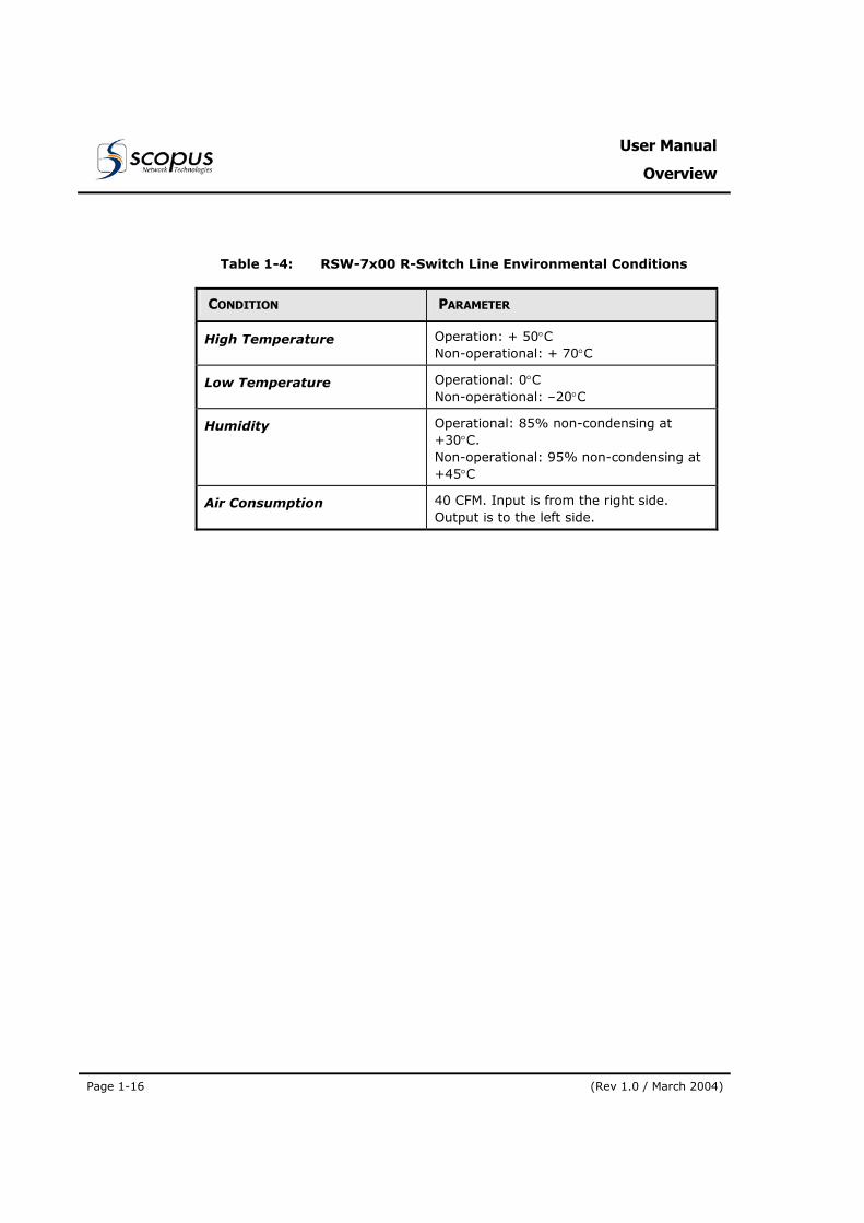
Table 1-4: RSW-7x00 R-Switch Line Environmental Conditions
CONDITION PARAMETER
High Temperature Operation: + 50°C Non-operational: + 70°C
Low Temperature Operational: 0°C Non-operational: –20°C
Humidity Operational: 85% non-condensing at +30°C. Non-operational: 95% non-condensing at +45°C
Air Consumption 40 CFM. Input is from the right side. Output is to the left side.
CODICO® RSW-7x00 Line
Redundancy Switches
Scopus Documents (p/n 100480) Page 2-1
Section 2. INSTALLATION
2.1. GENERAL This chapter describes the procedures required for installation of CODICO®
RSW-7x00 Line of Redundancy Switches (R-Switches).
2.2. INSTALLATION INFORMATION 2.2.1. Safety Precautions
To avoid injury to users and prevent equipment damage, observe the following
precautions:
• Only Scopus Network Technologies trained personnel should perform equipment installation, service and maintenance. Do no permit unqualified personnel to operate the unit.
• To prevent damage by lightning, the RSW-7x00 R-Switch must be grounded according to local regulations.
• Do not move or ship equipment unless it is properly packed in its original wrapping and shipping containers.
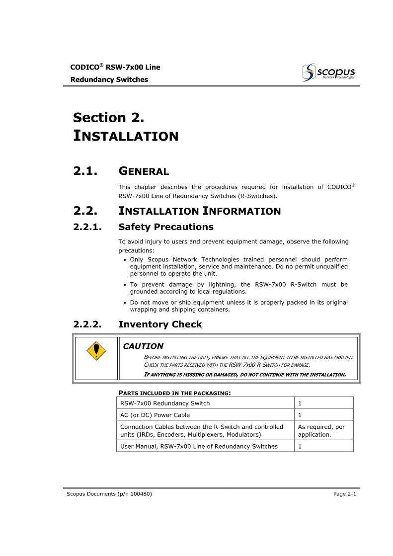
2.2.2. Inventory Check
CAUTION BEFORE INSTALLING THE UNIT, ENSURE THAT ALL THE EQUIPMENT TO BE INSTALLED HAS ARRIVED. CHECK THE PARTS RECEIVED WITH THE RSW-7X00 R-SWITCH FOR DAMAGE.
IF ANYTHING IS MISSING OR DAMAGED, DO NOT CONTINUE WITH THE INSTALLATION.
PARTS INCLUDED IN THE PACKAGING:
RSW-7x00 Redundancy Switch 1
AC (or DC) Power Cable 1
Connection Cables between the R-Switch and controlled units (IRDs, Encoders, Multiplexers, Modulators)
As required, per application.
User Manual, RSW-7x00 Line of Redundancy Switches 1
User Manual
Installation
Page 2-2 (Rev 1.0 / March 2004)
2.3. MECHANICAL INSTALLATION
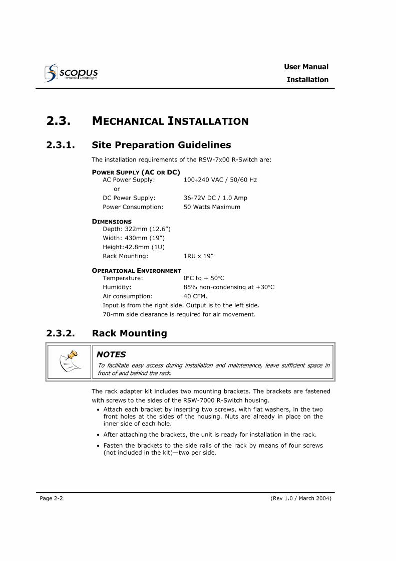
2.3.1. Site Preparation Guidelines The installation requirements of the RSW-7x00 R-Switch are:
POWER SUPPLY (AC OR DC) AC Power Supply: 100÷240 VAC / 50/60 Hz
or
DC Power Supply: 36-72V DC / 1.0 Amp
Power Consumption: 50 Watts Maximum
DIMENSIONS Depth: 322mm (12.6”)
Width: 430mm (19”)
Height: 42.8mm (1U)
Rack Mounting: 1RU x 19”
OPERATIONAL ENVIRONMENT Temperature: 0°C to + 50°C
Humidity: 85% non-condensing at +30°C
Air consumption: 40 CFM.
Input is from the right side. Output is to the left side.
70-mm side clearance is required for air movement.
2.3.2. Rack Mounting
NOTES To facilitate easy access during installation and maintenance, leave sufficient space in front of and behind the rack.
The rack adapter kit includes two mounting brackets. The brackets are fastened
with screws to the sides of the RSW-7000 R-Switch housing.
• Attach each bracket by inserting two screws, with flat washers, in the two front holes at the sides of the housing. Nuts are already in place on the inner side of each hole.
• After attaching the brackets, the unit is ready for installation in the rack.
• Fasten the brackets to the side rails of the rack by means of four screws (not included in the kit)—two per side.
CODICO® RSW-7x00 Line
Redundancy Switches
Scopus Documents (p/n 100480) Page 2-3
2.4. ELECTRICAL INSTALLATION
2.4.1. Power and Ground Connection The RSW-7x00 R-Switch can be supplied with an AC or DC Power Supply. Power
and ground connection for each option is detailed in the following paragraphs.
WARNING
ENSURE THAT A QUALIFIED ELECTRICIAN HAS INSTALLED THE AC POWER SUPPLY ACCORDING TO
POWER AUTHORITY REGULATIONS.
ALL POWERING SHOULD BE GROUNDED IN ACCORDANCE WITH LOCAL REGULATIONS.
IN ANY RACK INSTALLATION, ENSURE THAT THE RACK HAS BEEN PROPERLY GROUNDED.
DO NOT CONNECT AC POWER UNTIL YOU HAVE VERIFIED THAT THE LINE VOLTAGE IS CORRECT AND
THE PROPER FUSES ARE INSTALLED. FAILURE TO DO SO COULD RESULT IN ELECTRICAL SHOCK
NOTES As with any other mission-critical electronic device, the use of a UPS (Uninterrupted Power Supply) and an AVR (Automated Voltage Regulation) is highly recommended to ensure proper operation of the RSW-7x00 R-Switch.
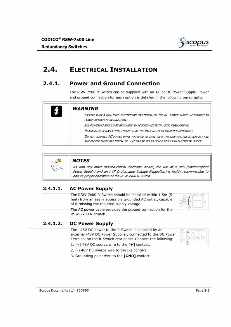
2.4.1.1. AC Power Supply The RSW-7x00 R-Switch should be installed within 1.5m (5 feet) from an easily accessible grounded AC outlet, capable of furnishing the required supply voltage.
The AC power cable provides the ground connection for the RSW-7x00 R-Switch.
2.4.1.2. DC Power Supply The –48V DC power to the R-Switch is supplied by an external -48V DC Power Supplier, connected to the DC Power Terminal on the R-Switch rear panel. Connect the following:
1. (+) 48V DC source wire to the [+] contact.
2. (-) 48V DC source wire to the [-] contact.
3. Grounding point wire to the [GND] contact.
User Manual
Installation
Page 2-4 (Rev 1.0 / March 2004)
2.4.2. Interconnecting Cabling Installation
2.4.2.1. 1+1 Decoders Redundancy Installation
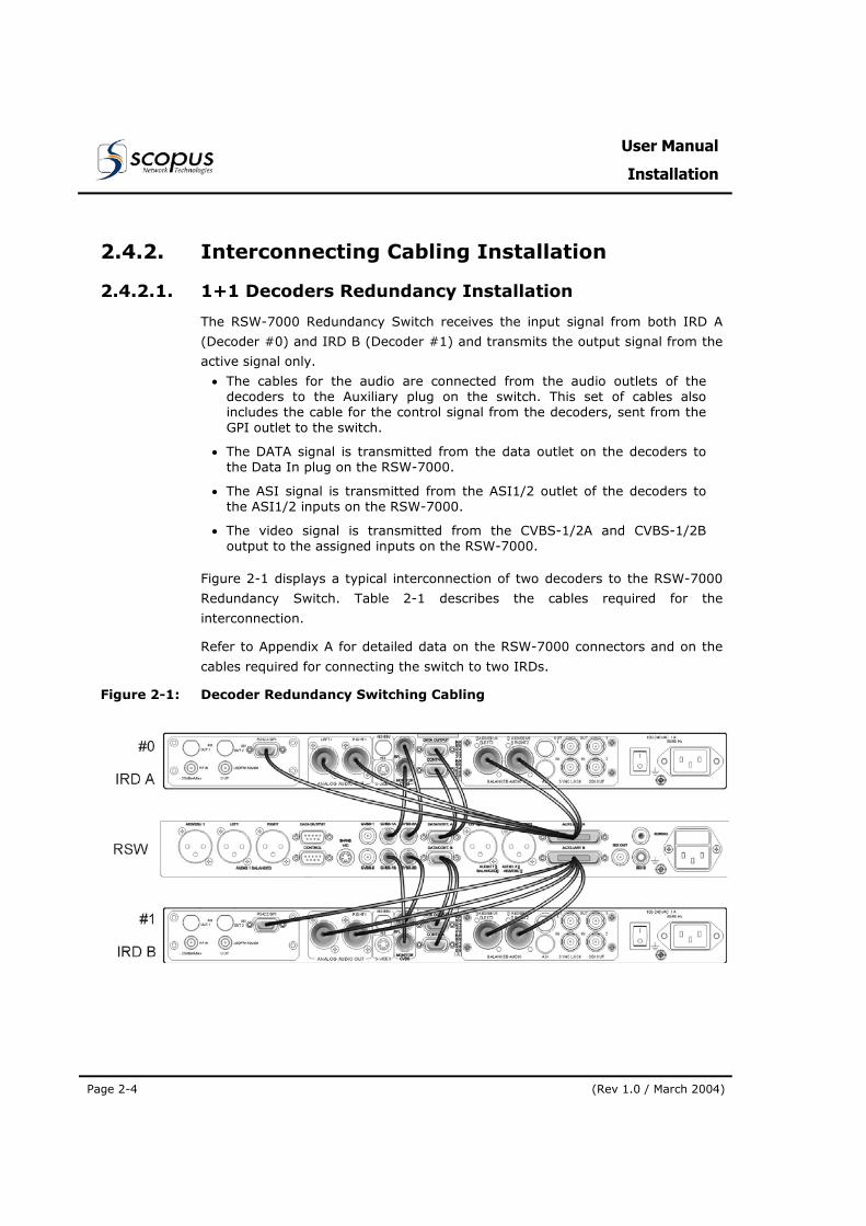
The RSW-7000 Redundancy Switch receives the input signal from both IRD A
(Decoder #0) and IRD B (Decoder #1) and transmits the output signal from the
active signal only.
• The cables for the audio are connected from the audio outlets of the decoders to the Auxiliary plug on the switch. This set of cables also includes the cable for the control signal from the decoders, sent from the GPI outlet to the switch.
• The DATA signal is transmitted from the data outlet on the decoders to the Data In plug on the RSW-7000.
• The ASI signal is transmitted from the ASI1/2 outlet of the decoders to the ASI1/2 inputs on the RSW-7000.
• The video signal is transmitted from the CVBS-1/2A and CVBS-1/2B output to the assigned inputs on the RSW-7000.
Figure 2-1 displays a typical interconnection of two decoders to the RSW-7000
Redundancy Switch. Table 2-1 describes the cables required for the
interconnection.
Refer to Appendix A for detailed data on the RSW-7000 connectors and on the
cables required for connecting the switch to two IRDs.
Figure 2-1: Decoder Redundancy Switching Cabling
CODICO® RSW-7x00 Line
Redundancy Switches
Scopus Documents (p/n 100480) Page 2-5
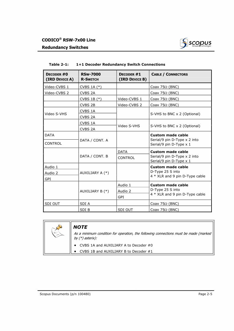
Table 2-1: 1+1 Decoder Redundancy Switch Connections
DECODER #0 (IRD DEVICE A)
RSW-7000 R-SWITCH
DECODER #1 (IRD DEVICE B)
CABLE / CONNECTORS
Video-CVBS 1 CVBS 1A (*) Coax 75Ω (BNC)
Video-CVBS 2 CVBS 2A Coax 75Ω (BNC)
CVBS 1B (*) Video-CVBS 1 Coax 75Ω (BNC)
CVBS 2B Video-CVBS 2 Coax 75Ω (BNC)
CVBS 1A Video S-VHS
CVBS 2A
S-VHS to BNC x 2 (Optional)
CVBS 1A
CVBS 2A Video S-VHS S-VHS to BNC x 2 (Optional)
DATA
CONTROL DATA / CONT. A
Custom made cable Serial/9 pin D-Type x 2 into Serial/9 pin D-Type x 1
DATA DATA / CONT. B CONTROL
Custom made cable Serial/9 pin D-Type x 2 into Serial/9 pin D-Type x 1
Audio 1
Audio 2
GPI
AUXILIARY A (*)
Custom made cable D-Type 25 S into 4 * XLR and 9 pin D-Type cable
Audio 1
Audio 2
AUXILIARY B (*)
GPI
Custom made cable D-Type 25 S into 4 * XLR and 9 pin D-Type cable
SDI OUT SDI A Coax 75Ω (BNC)
SDI B SDI OUT Coax 75Ω (BNC)
NOTE As a minimum condition for operation, the following connections must be made (marked by (*) asterix):
• CVBS 1A and AUXILIARY A to Decoder #0
• CVBS 1B and AUXILIARY B to Decoder #1
User Manual
Installation
Page 2-6 (Rev 1.0 / March 2004)
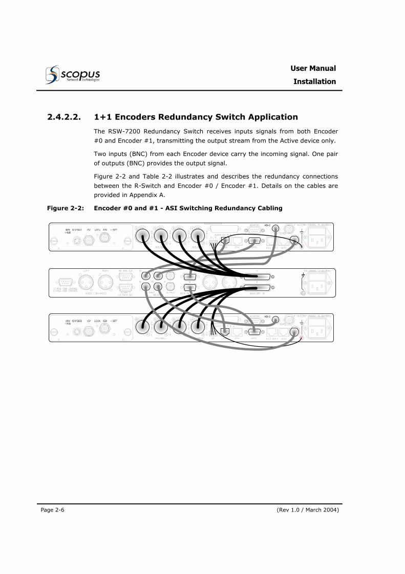
2.4.2.2. 1+1 Encoders Redundancy Switch Application
The RSW-7200 Redundancy Switch receives inputs signals from both Encoder
#0 and Encoder #1, transmitting the output stream from the Active device only.
Two inputs (BNC) from each Encoder device carry the incoming signal. One pair
of outputs (BNC) provides the output signal.
Figure 2-2 and Table 2-2 illustrates and describes the redundancy connections
between the R-Switch and Encoder #0 / Encoder #1. Details on the cables are
provided in Appendix A.
Figure 2-2: Encoder #0 and #1 - ASI Switching Redundancy Cabling
ASI-2
ASI-2
CODICO® RSW-7x00 Line
Redundancy Switches
Scopus Documents (p/n 100480) Page 2-7
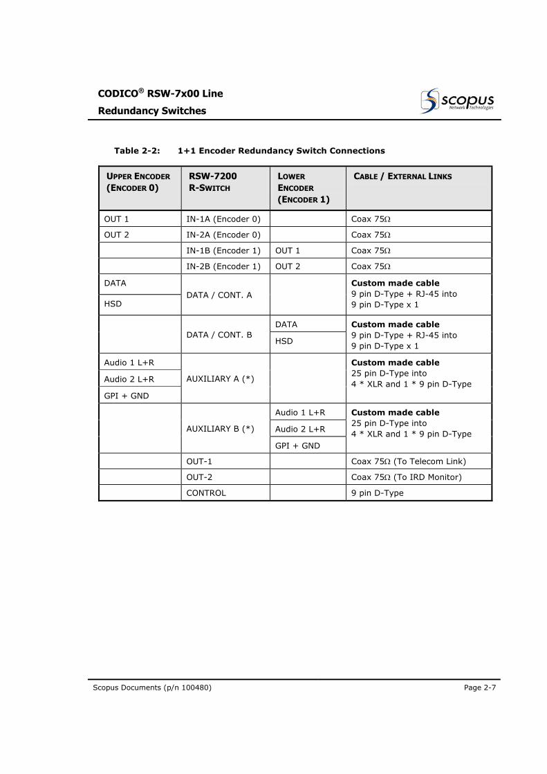
Table 2-2: 1+1 Encoder Redundancy Switch Connections
UPPER ENCODER (ENCODER 0)
RSW-7200 R-SWITCH
LOWER
ENCODER (ENCODER 1)
CABLE / EXTERNAL LINKS
OUT 1 IN-1A (Encoder 0) Coax 75Ω
OUT 2 IN-2A (Encoder 0) Coax 75Ω
IN-1B (Encoder 1) OUT 1 Coax 75Ω
IN-2B (Encoder 1) OUT 2 Coax 75Ω
DATA
HSD DATA / CONT. A
Custom made cable 9 pin D-Type + RJ-45 into 9 pin D-Type x 1
DATA DATA / CONT. B
HSD
Custom made cable 9 pin D-Type + RJ-45 into 9 pin D-Type x 1
Audio 1 L+R
Audio 2 L+R
GPI + GND
AUXILIARY A (*)
Custom made cable 25 pin D-Type into 4 * XLR and 1 * 9 pin D-Type
Audio 1 L+R
Audio 2 L+R
AUXILIARY B (*)
GPI + GND
Custom made cable 25 pin D-Type into 4 * XLR and 1 * 9 pin D-Type
OUT-1 Coax 75Ω (To Telecom Link)
OUT-2 Coax 75Ω (To IRD Monitor)
CONTROL 9 pin D-Type
User Manual
Installation
Page 2-8 (Rev 1.0 / March 2004)
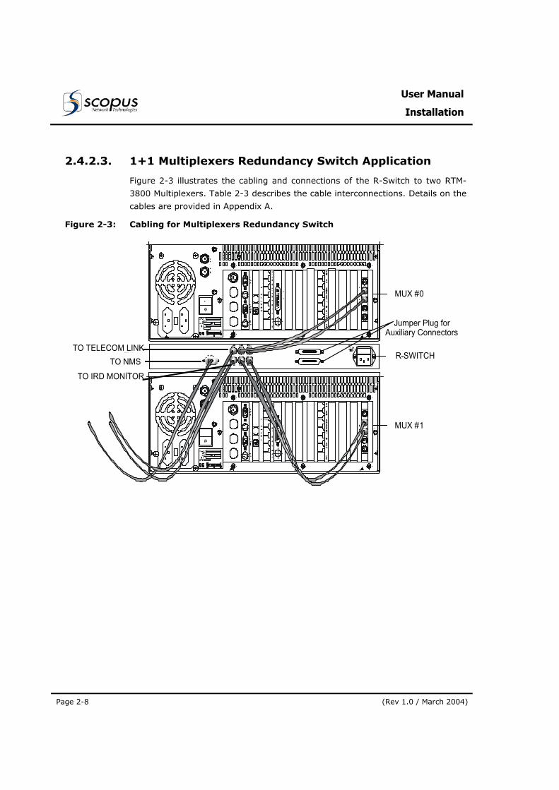
2.4.2.3. 1+1 Multiplexers Redundancy Switch Application
Figure 2-3 illustrates the cabling and connections of the R-Switch to two RTM-
3800 Multiplexers. Table 2-3 describes the cable interconnections. Details on the
cables are provided in Appendix A.
Figure 2-3: Cabling for Multiplexers Redundancy Switch
MUX #0
R-SWITCH
MUX #1
TO TELECOM LINKTO NMS
TO IRD MONITOR
Jumper Plug forAuxiliary Connectors
CODICO® RSW-7x00 Line
Redundancy Switches
Scopus Documents (p/n 100480) Page 2-9
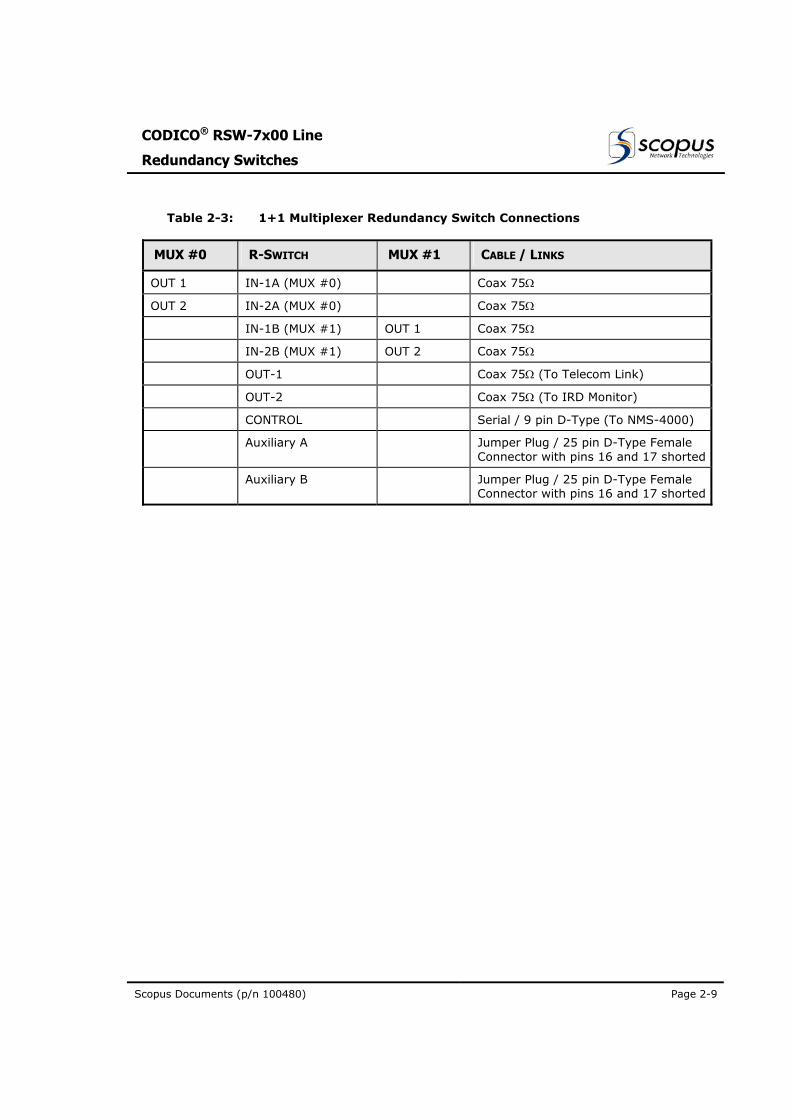
Table 2-3: 1+1 Multiplexer Redundancy Switch Connections
MUX #0 R-SWITCH MUX #1 CABLE / LINKS
OUT 1 IN-1A (MUX #0) Coax 75Ω
OUT 2 IN-2A (MUX #0) Coax 75Ω
IN-1B (MUX #1) OUT 1 Coax 75Ω
IN-2B (MUX #1) OUT 2 Coax 75Ω
OUT-1 Coax 75Ω (To Telecom Link)
OUT-2 Coax 75Ω (To IRD Monitor)
CONTROL Serial / 9 pin D-Type (To NMS-4000)
Auxiliary A Jumper Plug / 25 pin D-Type Female Connector with pins 16 and 17 shorted
Auxiliary B Jumper Plug / 25 pin D-Type Female Connector with pins 16 and 17 shorted

CODICO® RSW-7x00 Line
Redundancy Switches
Scopus Documents (p/n 100480) Page 3-1
Section 3. R-SWITCH OPERATION
3.1. GENERAL
This chapter provides the information required for efficient and effective
operation of the RSW-7x00 Line redundancy switches. It includes theoretical
background for the switch operation and detailed description of the operating
functions.
3.2. R-SWITCH FRONT PANEL OPERATION
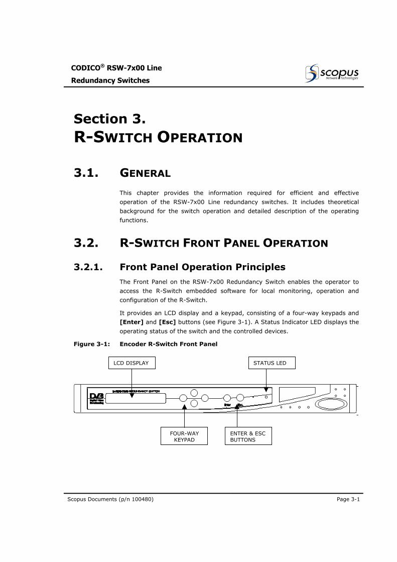
3.2.1. Front Panel Operation Principles The Front Panel on the RSW-7x00 Redundancy Switch enables the operator to
access the R-Switch embedded software for local monitoring, operation and
configuration of the R-Switch.
It provides an LCD display and a keypad, consisting of a four-way keypads and
[Enter] and [Esc] buttons (see Figure 3-1). A Status Indicator LED displays the
operating status of the switch and the controlled devices.
Figure 3-1: Encoder R-Switch Front Panel
LCD DISPLAY
FOUR-WAY KEYPAD
ENTER & ESC BUTTONS
STATUS LED
User Manual
R-Switch Operation
Page 3-2 (Rev 1.0 / March 2004)
LCD The Liquid Crystal Display (LCD) is an alphanumeric display used to display the front panel control menu options, input control parameters and status information. It also displays system data and system status messages.
FOUR WAY TOUCH PAD The Four Way ( [(Left] / [Right] / [Up] / [Down]) touch pad enables navigation in the menus by moving UP, DOWN, LEFT or RIGHT, respectively, in the information displayed on the LCD.
[ENTER] TOUCH PAD Pressing the [Enter] touch pad confirms a selection or proceeds to the next menu/item.
[ESC] TOUCH PAD Pressing the [Esc] touch pad exits from the current position or returns to the Status Message at the top of the menus.
It also used to disable the warning tone buzzer.
STATUS INDICATOR LED The Status Indicator LED uses the following legend:
Constant Green:
R-Switch and controlled devices are operating correctly
Flashing Green:
A malfunction was detected. The device status is changed to “FAIL” and the alarm buzzer is activated.
ALARM BUZZER Aural alarm indicator.
The R-Switch buzzer is activated for 3 seconds at power up.
In normal operation, the buzzer is activated when a failure is detected, either in the R-Switch or in any of the A / B Devices. A GPI output reply reflects the buzzer status.
NOTES To silence the buzzer, proceed as follows: • In “LOCAL” mode, press the [Esc] key on the Front Panel to disable the buzz tone.
• In “REMOTE” mode, send command “f” from the terminal.
CODICO® RSW-7x00 Line
Redundancy Switches
Scopus Documents (p/n 100480) Page 3-3
3.2.2. Front Panel Operation Concept The R-Switch operation from the front panel is performed in a two-step
(Navigate and Display, Change and Confirm) procedure. The following describes
how to use the controls on the Front Panel:
NAVIGATE AND DISPLAY STEP:
The first step consists of navigating in the menu tree and finding the parameter
in the menu:
• The [Up] / [Down] touch pads are used to move between the parameters in the menu tree.
• A parameter is selected by pressing the [Enter] touch pad.
• The [Esc] touch pad returns one level back.
CHANGE AND CONFIRM STEP:
The second step changes the current option to a new option, by selecting it out
of a pre-defined list:
• The [Right] touch pad enables access to the list of options.
• The currently active option is marked by a left arrow “”, on the right side of the LCD.
• The [Up] / [Down] touch pads are used to navigate between the options.
• Pressing [Enter] activates the selected option and exits to the Menu tree.
• [Esc] exits to the Menu tree without changing the currently active option.
NOTE When powered down, the R-Switch is set to “Device A Active” by default.
User Manual
R-Switch Operation
Page 3-4 (Rev 1.0 / March 2004)
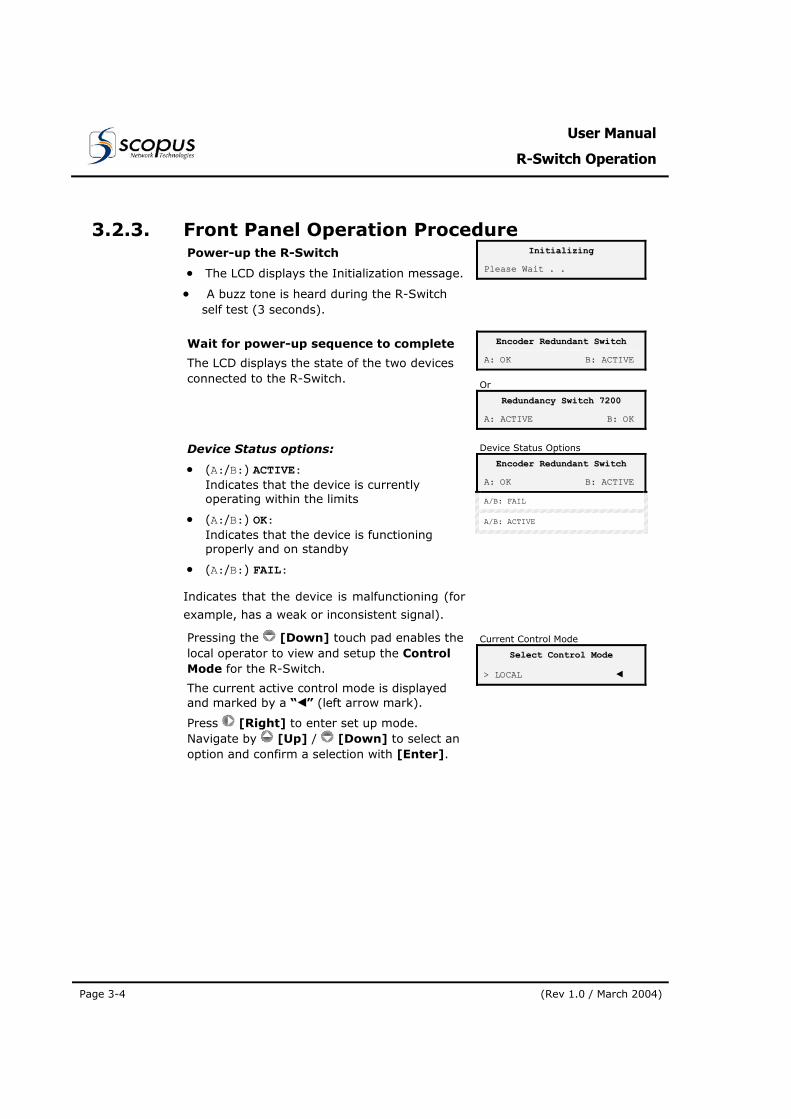
3.2.3. Front Panel Operation Procedure Power-up the R-Switch
• The LCD displays the Initialization message.
• A buzz tone is heard during the R-Switch self test (3 seconds).
IInniittiiaalliizziinngg
PPlleeaassee WWaaiitt .. ..
Wait for power-up sequence to complete
The LCD displays the state of the two devices connected to the R-Switch.
EEnnccooddeerr RReedduunnddaanntt SSwwiittcchh
AA:: OOKK BB:: AACCTTIIVVEE
Or
RReedduunnddaannccyy SSwwiittcchh 77220000
AA:: AACCTTIIVVEE BB:: OOKK
Device Status options:
• (A:/B:) ACTIVE: Indicates that the device is currently operating within the limits
• (A:/B:) OK: Indicates that the device is functioning properly and on standby
• (A:/B:) FAIL:
Indicates that the device is malfunctioning (for
example, has a weak or inconsistent signal).
Device Status Options
EEnnccooddeerr RReedduunnddaanntt SSwwiittcchh
AA:: OOKK BB:: AACCTTIIVVEE
AA//BB:: FFAAIILL
AA//BB:: AACCTTIIVVEE
Pressing the [Down] touch pad enables the local operator to view and setup the Control Mode for the R-Switch.
The current active control mode is displayed and marked by a “” (left arrow mark).
Press [Right] to enter set up mode. Navigate by [Up] / [Down] to select an option and confirm a selection with [Enter].
Current Control Mode
SSeelleecctt CCoonnttrrooll MMooddee
>> LLOOCCAALL
CODICO® RSW-7x00 Line
Redundancy Switches
Scopus Documents (p/n 100480) Page 3-5
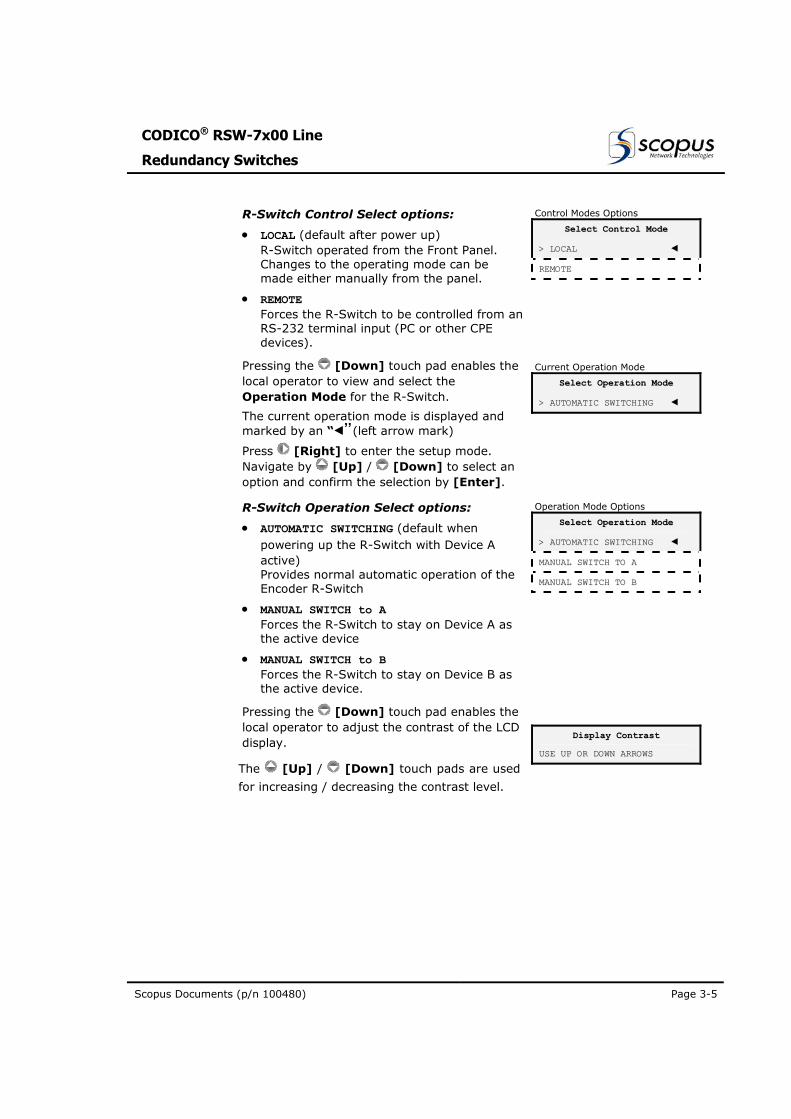
R-Switch Control Select options:
• LOCAL (default after power up) R-Switch operated from the Front Panel. Changes to the operating mode can be made either manually from the panel.
• REMOTE Forces the R-Switch to be controlled from an RS-232 terminal input (PC or other CPE devices).
Control Modes Options
SSeelleecctt CCoonnttrrooll MMooddee
>> LLOOCCAALL
RREEMMOOTTEE
Pressing the [Down] touch pad enables the local operator to view and select the Operation Mode for the R-Switch.
The current operation mode is displayed and marked by an “”(left arrow mark)
Press [Right] to enter the setup mode. Navigate by [Up] / [Down] to select an option and confirm the selection by [Enter].
Current Operation Mode
SSeelleecctt OOppeerraattiioonn MMooddee
>> AAUUTTOOMMAATTIICC SSWWIITTCCHHIINNGG
R-Switch Operation Select options:
• AUTOMATIC SWITCHING (default when powering up the R-Switch with Device A active) Provides normal automatic operation of the Encoder R-Switch
• MANUAL SWITCH to A Forces the R-Switch to stay on Device A as the active device
• MANUAL SWITCH to B Forces the R-Switch to stay on Device B as the active device.
Operation Mode Options
SSeelleecctt OOppeerraattiioonn MMooddee
>> AAUUTTOOMMAATTIICC SSWWIITTCCHHIINNGG
MMAANNUUAALL SSWWIITTCCHH TTOO AA
MMAANNUUAALL SSWWIITTCCHH TTOO BB
Pressing the [Down] touch pad enables the local operator to adjust the contrast of the LCD display.
The [Up] / [Down] touch pads are used
for increasing / decreasing the contrast level.
DDiissppllaayy CCoonnttrraasstt
UUSSEE UUPP OORR DDOOWWNN AARRRROOWWSS
User Manual
R-Switch Operation
Page 3-6 (Rev 1.0 / March 2004)
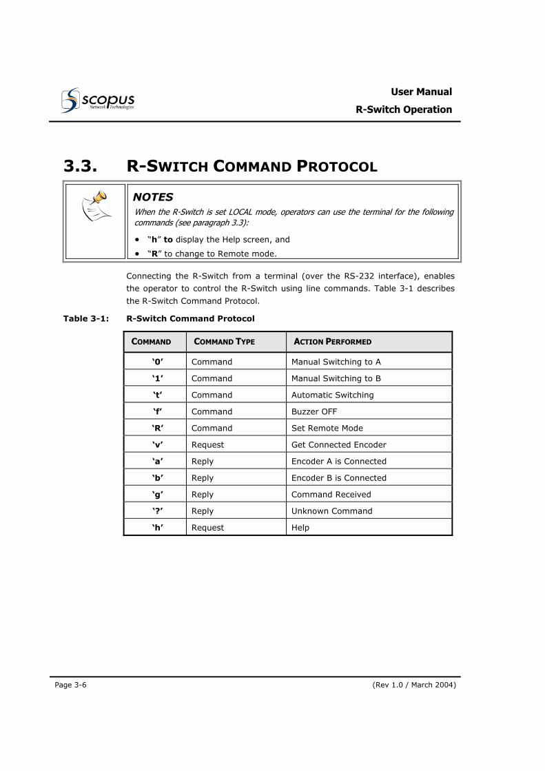
3.3. R-SWITCH COMMAND PROTOCOL
NOTES When the R-Switch is set LOCAL mode, operators can use the terminal for the following commands (see paragraph 3.3):
• “h” to display the Help screen, and
• “R” to change to Remote mode.
Connecting the R-Switch from a terminal (over the RS-232 interface), enables
the operator to control the R-Switch using line commands. Table 3-1 describes
the R-Switch Command Protocol.
Table 3-1: R-Switch Command Protocol
COMMAND COMMAND TYPE ACTION PERFORMED
‘0’ Command Manual Switching to A
‘1’ Command Manual Switching to B
‘t’ Command Automatic Switching
‘f’ Command Buzzer OFF
‘R’ Command Set Remote Mode
‘v’ Request Get Connected Encoder
‘a’ Reply Encoder A is Connected
‘b’ Reply Encoder B is Connected
‘g’ Reply Command Received
‘?’ Reply Unknown Command
‘h’ Request Help
CODICO® RSW-7x00 Line
Redundancy Switches
Scopus Documents (p/n 100480) Page 1
Appendix A. CONNECTORS AND CABLES
A.1 RSW-7000 CONNECTOR AND CABLES DATA
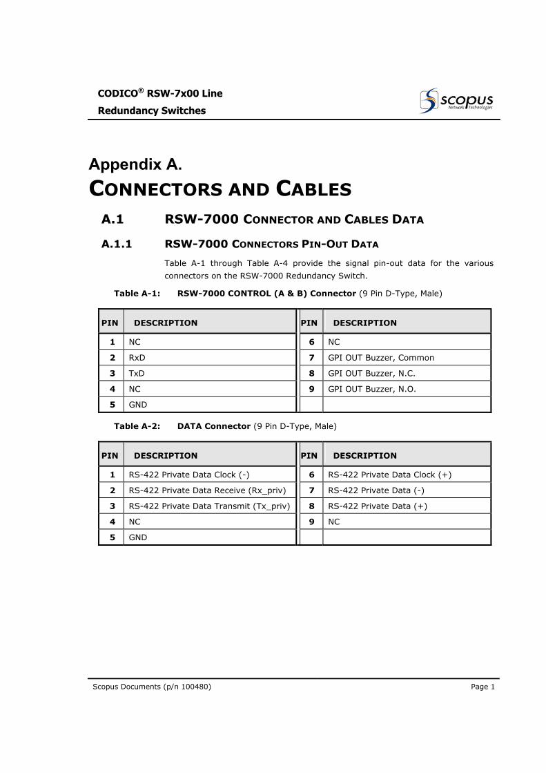
A.1.1 RSW-7000 CONNECTORS PIN-OUT DATA
Table A-1 through Table A-4 provide the signal pin-out data for the various
connectors on the RSW-7000 Redundancy Switch.
Table A-1: RSW-7000 CONTROL (A & B) Connector (9 Pin D-Type, Male)
PIN DESCRIPTION PIN DESCRIPTION
1 NC 6 NC
2 RxD 7 GPI OUT Buzzer, Common
3 TxD 8 GPI OUT Buzzer, N.C.
4 NC 9 GPI OUT Buzzer, N.O.
5 GND
Table A-2: DATA Connector (9 Pin D-Type, Male)
PIN DESCRIPTION PIN DESCRIPTION
1 RS-422 Private Data Clock (-) 6 RS-422 Private Data Clock (+)
2 RS-422 Private Data Receive (Rx_priv) 7 RS-422 Private Data (-)
3 RS-422 Private Data Transmit (Tx_priv) 8 RS-422 Private Data (+)
4 NC 9 NC
5 GND
User Manual
R-Switch Operation
Page 2 (Rev 1.0 / March 2004)
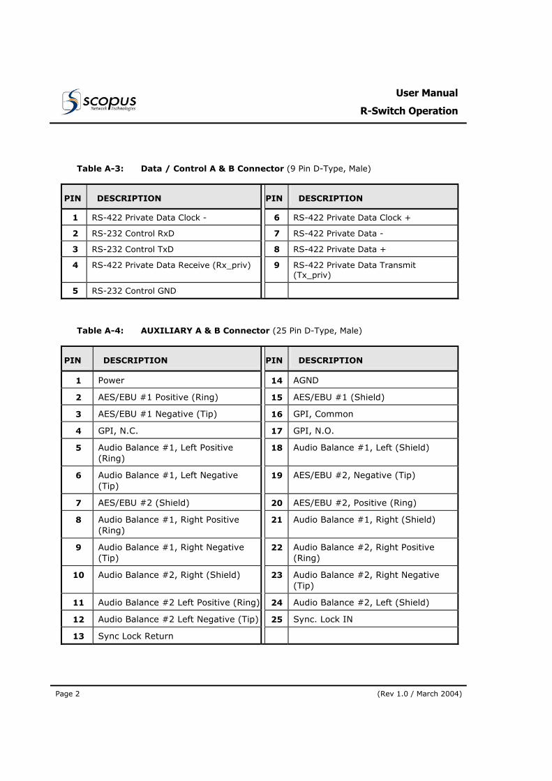
Table A-3: Data / Control A & B Connector (9 Pin D-Type, Male)
PIN DESCRIPTION PIN DESCRIPTION
1 RS-422 Private Data Clock - 6 RS-422 Private Data Clock +
2 RS-232 Control RxD 7 RS-422 Private Data -
3 RS-232 Control TxD 8 RS-422 Private Data +
4 RS-422 Private Data Receive (Rx_priv) 9 RS-422 Private Data Transmit (Tx_priv)
5 RS-232 Control GND
Table A-4: AUXILIARY A & B Connector (25 Pin D-Type, Male)
PIN DESCRIPTION PIN DESCRIPTION
1 Power 14 AGND
2 AES/EBU #1 Positive (Ring) 15 AES/EBU #1 (Shield)
3 AES/EBU #1 Negative (Tip) 16 GPI, Common
4 GPI, N.C. 17 GPI, N.O.
5 Audio Balance #1, Left Positive (Ring)
18 Audio Balance #1, Left (Shield)
6 Audio Balance #1, Left Negative (Tip)
19 AES/EBU #2, Negative (Tip)
7 AES/EBU #2 (Shield) 20 AES/EBU #2, Positive (Ring)
8 Audio Balance #1, Right Positive (Ring)
21 Audio Balance #1, Right (Shield)
9 Audio Balance #1, Right Negative (Tip)
22 Audio Balance #2, Right Positive (Ring)
10 Audio Balance #2, Right (Shield) 23 Audio Balance #2, Right Negative (Tip)
11 Audio Balance #2 Left Positive (Ring) 24 Audio Balance #2, Left (Shield)
12 Audio Balance #2 Left Negative (Tip) 25 Sync. Lock IN
13 Sync Lock Return
CODICO® RSW-7x00 Line
Redundancy Switches
Scopus Documents (p/n 100480) Page 3
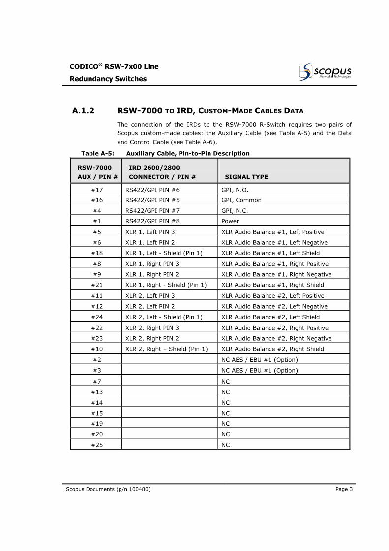
A.1.2 RSW-7000 TO IRD, CUSTOM-MADE CABLES DATA
The connection of the IRDs to the RSW-7000 R-Switch requires two pairs of
Scopus custom-made cables: the Auxiliary Cable (see Table A-5) and the Data
and Control Cable (see Table A-6).
Table A-5: Auxiliary Cable, Pin-to-Pin Description
RSW-7000
AUX / PIN #
IRD 2600/2800
CONNECTOR / PIN #
SIGNAL TYPE
#17 RS422/GPI PIN #6 GPI, N.O.
#16 RS422/GPI PIN #5 GPI, Common
#4 RS422/GPI PIN #7 GPI, N.C.
#1 RS422/GPI PIN #8 Power
#5 XLR 1, Left PIN 3 XLR Audio Balance #1, Left Positive
#6 XLR 1, Left PIN 2 XLR Audio Balance #1, Left Negative
#18 XLR 1, Left - Shield (Pin 1) XLR Audio Balance #1, Left Shield
#8 XLR 1, Right PIN 3 XLR Audio Balance #1, Right Positive
#9 XLR 1, Right PIN 2 XLR Audio Balance #1, Right Negative
#21 XLR 1, Right - Shield (Pin 1) XLR Audio Balance #1, Right Shield
#11 XLR 2, Left PIN 3 XLR Audio Balance #2, Left Positive
#12 XLR 2, Left PIN 2 XLR Audio Balance #2, Left Negative
#24 XLR 2, Left - Shield (Pin 1) XLR Audio Balance #2, Left Shield
#22 XLR 2, Right PIN 3 XLR Audio Balance #2, Right Positive
#23 XLR 2, Right PIN 2 XLR Audio Balance #2, Right Negative
#10 XLR 2, Right – Shield (Pin 1) XLR Audio Balance #2, Right Shield
#2 NC AES / EBU #1 (Option)
#3 NC AES / EBU #1 (Option)
#7 NC
#13 NC
#14 NC
#15 NC
#19 NC
#20 NC
#25 NC
User Manual
R-Switch Operation
Page 4 (Rev 1.0 / March 2004)
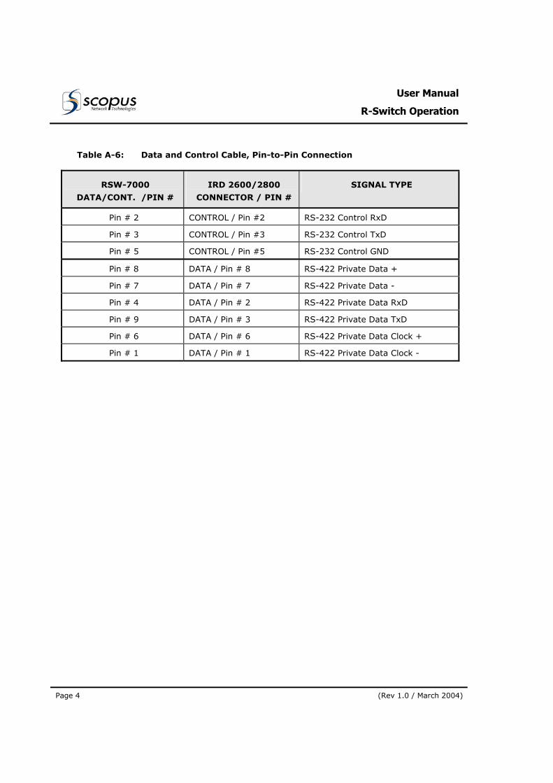
Table A-6: Data and Control Cable, Pin-to-Pin Connection
RSW-7000
DATA/CONT. /PIN #
IRD 2600/2800
CONNECTOR / PIN #
SIGNAL TYPE
Pin # 2 CONTROL / Pin #2 RS-232 Control RxD
Pin # 3 CONTROL / Pin #3 RS-232 Control TxD
Pin # 5 CONTROL / Pin #5 RS-232 Control GND
Pin # 8 DATA / Pin # 8 RS-422 Private Data +
Pin # 7 DATA / Pin # 7 RS-422 Private Data -
Pin # 4 DATA / Pin # 2 RS-422 Private Data RxD
Pin # 9 DATA / Pin # 3 RS-422 Private Data TxD
Pin # 6 DATA / Pin # 6 RS-422 Private Data Clock +
Pin # 1 DATA / Pin # 1 RS-422 Private Data Clock -
CODICO® RSW-7x00 Line
Redundancy Switches
Scopus Documents (p/n 100480) Page 5
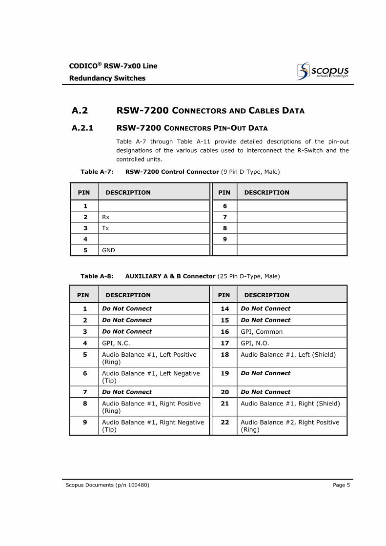
A.2 RSW-7200 CONNECTORS AND CABLES DATA
A.2.1 RSW-7200 CONNECTORS PIN-OUT DATA
Table A-7 through Table A-11 provide detailed descriptions of the pin-out
designations of the various cables used to interconnect the R-Switch and the
controlled units.
Table A-7: RSW-7200 Control Connector (9 Pin D-Type, Male)
PIN DESCRIPTION PIN DESCRIPTION
1 6
2 Rx 7
3 Tx 8
4 9
5 GND
Table A-8: AUXILIARY A & B Connector (25 Pin D-Type, Male)
PIN DESCRIPTION PIN DESCRIPTION
1 Do Not Connect 14 Do Not Connect
2 Do Not Connect 15 Do Not Connect
3 Do Not Connect 16 GPI, Common
4 GPI, N.C. 17 GPI, N.O.
5 Audio Balance #1, Left Positive (Ring)
18 Audio Balance #1, Left (Shield)
6 Audio Balance #1, Left Negative (Tip)
19 Do Not Connect
7 Do Not Connect 20 Do Not Connect
8 Audio Balance #1, Right Positive (Ring)
21 Audio Balance #1, Right (Shield)
9 Audio Balance #1, Right Negative (Tip)
22 Audio Balance #2, Right Positive (Ring)
User Manual
R-Switch Operation
Page 6 (Rev 1.0 / March 2004)
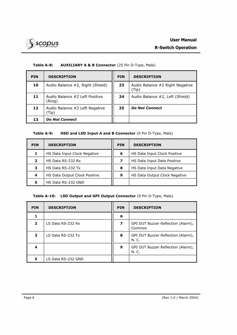
Table A-8: AUXILIARY A & B Connector (25 Pin D-Type, Male)
PIN DESCRIPTION PIN DESCRIPTION
10 Audio Balance #2, Right (Shield) 23 Audio Balance #2 Right Negative (Tip)
11 Audio Balance #2 Left Positive (Ring)
24 Audio Balance #2, Left (Shield)
12 Audio Balance #2 Left Negative (Tip)
25 Do Not Connect
13 Do Not Connect
Table A-9: HSD and LSD Input A and B Connector (9 Pin D-Type, Male)
PIN DESCRIPTION PIN DESCRIPTION
1 HS Data Input Clock Negative 6 HS Data Input Clock Positive
2 HS Data RS-232 Rx 7 HS Data Input Data Positive
3 HS Data RS-232 Tx 8 HS Data Input Data Negative
4 HS Data Output Clock Positive 9 HS Data Output Clock Negative
5 HS Data RS-232 GND
Table A-10: LSD Output and GPI Output Connector (9 Pin D-Type, Male)
PIN DESCRIPTION PIN DESCRIPTION
1 6
2 LS Data RS-232 Rx 7 GPI OUT Buzzer Reflection (Alarm), Common
3 LS Data RS-232 Tx 8 GPI OUT Buzzer Reflection (Alarm), N. C.
4 9 GPI OUT Buzzer Reflection (Alarm), N. C.
5 LS Data RS-232 GND
CODICO® RSW-7x00 Line
Redundancy Switches
Scopus Documents (p/n 100480) Page 7
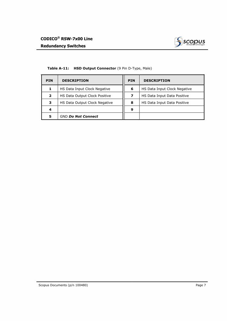
Table A-11: HSD Output Connector (9 Pin D-Type, Male)
PIN DESCRIPTION PIN DESCRIPTION
1 HS Data Input Clock Negative 6 HS Data Input Clock Negative
2 HS Data Output Clock Positive 7 HS Data Input Data Positive
3 HS Data Output Clock Negative 8 HS Data Input Data Positive
4 9
5 GND Do Not Connect
User Manual
R-Switch Operation
Page 8 (Rev 1.0 / March 2004)
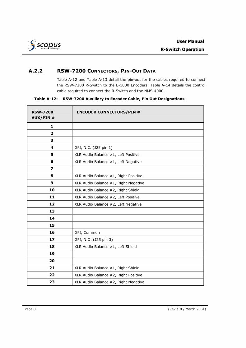
A.2.2 RSW-7200 CONNECTORS, PIN-OUT DATA
Table A-12 and Table A-13 detail the pin-out for the cables required to connect
the RSW-7200 R-Switch to the E-1000 Encoders. Table A-14 details the control
cable required to connect the R-Switch and the NMS-4000.
Table A-12: RSW-7200 Auxiliary to Encoder Cable, Pin Out Designations
RSW-7200
AUX/PIN #
ENCODER CONNECTORS/PIN #
1
2
3
4 GPI, N.C. (J25 pin 1)
5 XLR Audio Balance #1, Left Positive
6 XLR Audio Balance #1, Left Negative
7
8 XLR Audio Balance #1, Right Positive
9 XLR Audio Balance #1, Right Negative
10 XLR Audio Balance #2, Right Shield
11 XLR Audio Balance #2, Left Positive
12 XLR Audio Balance #2, Left Negative
13
14
15
16 GPI, Common
17 GPI, N.O. (J25 pin 3)
18 XLR Audio Balance #1, Left Shield
19
20
21 XLR Audio Balance #1, Right Shield
22 XLR Audio Balance #2, Right Positive
23 XLR Audio Balance #2, Right Negative
CODICO® RSW-7x00 Line
Redundancy Switches
Scopus Documents (p/n 100480) Page 9
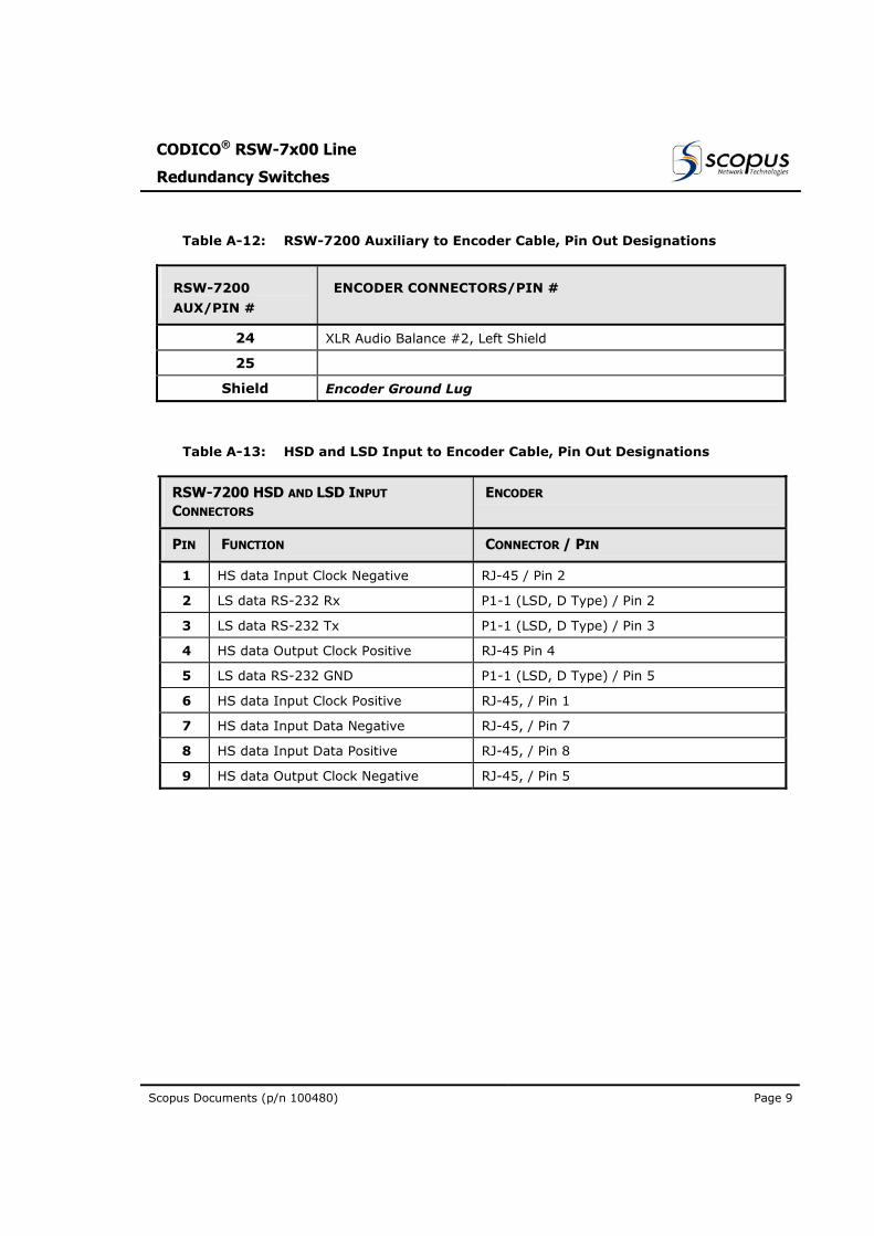
Table A-12: RSW-7200 Auxiliary to Encoder Cable, Pin Out Designations
RSW-7200
AUX/PIN #
ENCODER CONNECTORS/PIN #
24 XLR Audio Balance #2, Left Shield
25
Shield Encoder Ground Lug
Table A-13: HSD and LSD Input to Encoder Cable, Pin Out Designations
RSW-7200 HSD AND LSD INPUT
CONNECTORS ENCODER
PIN FUNCTION CONNECTOR / PIN
1 HS data Input Clock Negative RJ-45 / Pin 2
2 LS data RS-232 Rx P1-1 (LSD, D Type) / Pin 2
3 LS data RS-232 Tx P1-1 (LSD, D Type) / Pin 3
4 HS data Output Clock Positive RJ-45 Pin 4
5 LS data RS-232 GND P1-1 (LSD, D Type) / Pin 5
6 HS data Input Clock Positive RJ-45, / Pin 1
7 HS data Input Data Negative RJ-45, / Pin 7
8 HS data Input Data Positive RJ-45, / Pin 8
9 HS data Output Clock Negative RJ-45, / Pin 5
User Manual
R-Switch Operation
Page 10 (Rev 1.0 / March 2004)
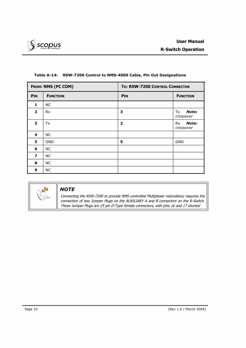
Table A-14: RSW-7200 Control to NMS-4000 Cable, Pin Out Designations
FROM: NMS (PC COM) TO: RSW-7200 CONTROL CONNECTOR
PIN FUNCTION PIN FUNCTION
1 NC
2 Rx 3 Tx Note: crossover
3 Tx 2 Rx Note: crossover
4 NC
5 GND 5 GND
6 NC
7 NC
8 NC
9 NC
NOTE Connecting the RSW-7200 to provide NMS controlled Multiplexer redundancy requires the connection of two Jumper Plugs on the AUXILIARY A and B connectors on the R-Switch.These Jumper Plugs are 25 pin D-Type female connectors, with pins 16 and 17 shorted


