PUSHING THE EDGE MSC12841-3 RT3 UTV STRAIGHT BLADE INSTALLATION & OWNER’S MANUAL TABLE OF CONTENTS SAFETY ..................................................................................................................................................... 2 INTRODUCTIONS ..................................................................................................................................... 5 TIPS ON PLOWING SNOW....................................................................................................................... 6 SNOWPLOW MOUNTING & REMOVAL PROCEDURE .......................................................................... 7 MAINTENANCE ......................................................................................................................................... 8 PUTTING PLOW INTO STORAGE ........................................................................................................... 8 TAKING PLOW OUT OF STORAGE ......................................................................................................... 8 SNOWPLOW ASSEMBLY PROCEDURE ................................................................................................. 9 ELECTRICAL SYSTEM WIRING PROCEDURE....................................................................................... 11 ELECTRICAL SYSTEM WIRING DIAGRAM ............................................................................................. 13 SPORT DUTY STRAIGHT BLADE ASSEMBLY DRAWING AND PARTS LIST ...................................... 14 ELECTRICAL SYSTEM WIRING SCHEMATIC (PLOW SIDE) ................................................................. 16 ELECTRICAL SYSTEM WIRING SCHEMATIC (VEHICLE SIDE) ............................................................ 17 RT3 STRAIGHT BLADE MANIFOLD WIRING DIAGRAMS ...................................................................... 18 HYDRAULIC POWER UNIT FILL PROCEDURE ...................................................................................... 19 HYDRAULIC VALVE ASSEMBLY PARTS LIST........................................................................................ 20 STRAIGHT BLADE CONTROLLER .......................................................................................................... 21 TROUBLESHOOTING GUIDE................................................................................................................... 22 RECOMMENDED PUSHBEAM HEIGHT .................................................................................................. 26 RECOMMENDED BOLT TORQUE ........................................................................................................... 26 WARRANTY ............................................................................................................................................... 27 Original Instructions BOSS PRODUCTS reserves the right under its continuous product improvement policy to change construction or design details and furnish equipment when so altered without reference to illustrations or specifications used herein. Patent: www.ttcopatents.com
SAFETY ..................................................................................................................................................... 2 INTRODUCTIONS ..................................................................................................................................... 5 TIPS ON PLOWING SNOW....................................................................................................................... 6 SNOWPLOW MOUNTING & REMOVAL PROCEDURE .......................................................................... 7 MAINTENANCE ......................................................................................................................................... 8 PUTTING PLOW INTO STORAGE ........................................................................................................... 8 TAKING PLOW OUT OF STORAGE ......................................................................................................... 8 SNOWPLOW ASSEMBLY PROCEDURE ................................................................................................. 9 ELECTRICAL SYSTEM WIRING PROCEDURE....................................................................................... 11 ELECTRICAL SYSTEM WIRING DIAGRAM ............................................................................................. 13 SPORT DUTY STRAIGHT BLADE ASSEMBLY DRAWING AND PARTS LIST ...................................... 14 ELECTRICAL SYSTEM WIRING SCHEMATIC (PLOW SIDE) ................................................................. 16 ELECTRICAL SYSTEM WIRING SCHEMATIC (VEHICLE SIDE) ............................................................ 17 RT3 STRAIGHT BLADE MANIFOLD WIRING DIAGRAMS ...................................................................... 18 HYDRAULIC POWER UNIT FILL PROCEDURE ...................................................................................... 19 HYDRAULIC VALVE ASSEMBLY PARTS LIST........................................................................................ 20 STRAIGHT BLADE CONTROLLER .......................................................................................................... 21 TROUBLESHOOTING GUIDE................................................................................................................... 22 RECOMMENDED PUSHBEAM HEIGHT .................................................................................................. 26 RECOMMENDED BOLT TORQUE ........................................................................................................... 26 WARRANTY ............................................................................................................................................... 27
Original Instructions
BOSS PRODUCTS reserves the right under its continuous product improvement policy to change construction or design details and furnish equipment when so altered without reference to illustrations or specifications used herein.
Patent: www.ttcopatents.com
Safety
2
Serious injury or death can result if you do not follow these instructions and procedures which are outlined further within your owner’s manual
NEVER exceed the vehicle’s Gross Vehicle Weight Rating or the Front or Rear Gross Axle Weight Ratings. Overloading could result in an accident or damage.
Read this manual and all labels carefully. Follow the operating procedures described.
Follow all Operator Safety instructions found in your UTV Owner’s Manual.
Follow all age restrictions found in your UTV Owner’s Manual.
When transporting, position plow so as not to block vision.
NEVER change blade position when traveling.
ALWAYS use LOW RANGE and never exceed 14 mph when plowing.
ALWAYS use LOW RANGE and never exceed 24 mph while transporting plow.
ALWAYS use LOW RANGE and never exceed 5 mph while operating plow.
Always lower blade when vehicle is not in use.
Make sure plow is properly attached before moving vehicle.
The 6’0” Sport Duty UTV Straight Blade Plow is intended for personal, non-commercial use. Any use of the plow in a commercial setting will void the plow warranty.
NEVER ride on Plow System
NEVER lift persons on Plow System.
NEVER get body parts between Plow System and vehicle while servicing or operating.
NEVER operate on steep inclines.
Operators should always use vehicle seat belts and all other applicable personal protective equipment while operating plow.
NEVER operate vehicle or plow unless Tire Pressure and Vehicle Ballast Requirements are satisfied.
Always remove ignition key and unplug Plow System before servicing.
Wear proper personal protection equipment when operating and servicing snowplow; including, but not limited to, clothing for cold weather and slippery surfaces.
Some snowplow components are very heavy – use properly rigged 1/2-ton minimum lifting device to maneuver heavy snowplow components.
Snowplow operating noise level below 70dB.
MSDS are available at www.bossplow.com.
Hydraulic component installation and maintenance must be performed by trained personnel.
Never place body parts between snowplow and vehicle.
When transporting be sure to properly secure your load. Proper load securing instructions are available at www.bossplow.com.
POTENTIAL HAZARD Operating Plow System without proper instruction WHAT CAN HAPPEN Loss of control, accident HOW TO AVOID THE HAZARD The risk of an accident is greatly increased if the operator does not know how to operate the Plow System properly in different situations. All operators must read and understand the Owner’s manual and instruction labels before operating the system.
POTENTIAL HAZARD Operating the vehicle with the Plow System not properly attached. The pins are not fully engaged. WHAT CAN HAPPEN Loss of control, accident HOW TO AVOID THE HAZARD Never operate the vehicle when the Plow System is not properly attached.
POTENTIAL HAZARD Operating the vehicle with the Plow System in a position that blocks your vision. WHAT CAN HAPPEN Collision with obstacle or another vehicle HOW TO AVOID THE HAZARD Never operate the vehicle when the Plow System is in a position that blocks your vision.
Safety
4
POTENTIAL HAZARD Positioning body parts on or between Plow System while operating Plow System or the vehicle. WHAT CAN HAPPEN Severe injury or death can occur if a person gets caught between moving parts or falls while vehicle is in motion. HOW TO AVOID THE HAZARD Never ride in, ride on, or stand next to Plow System while someone is operating it or the vehicle.
POTENTIAL HAZARD Exceeding recommended speed limits set for operation types. WHAT CAN HAPPEN Loss of control, accident HOW TO AVOID THE HAZARD Do not exceed recommended speed limits. Always travel at proper speed for terrain, visibility, operating conditions, and your experience.
POTENTIAL HAZARD Operating Plow System or vehicle with improper tire pressure or without recommended ballast. WHAT CAN HAPPEN Loss of control, accident HOW TO AVOID THE HAZARD Always maintain tire pressure and ballast requirements specified on www.bossplow.com for each UTV application.
Hydraulic oil can be harmful if ingested. If oil is ingested, DO NOT INDUCE VOMITTING. If conscious, give two cups of water. Get medical attention immediately. If hydraulic oil is spilled on skin, wash with soap and water. Get medical attention if irritation develops. Launder contaminated clothes before reuse. If hydraulic oil is exposed to eyes, flush eyes with water for 15 minutes. Get medical attention. If hydraulic oil fume inhalation causes adverse affects, remove exposed person to fresh air. Get medical attention.
Congratulations on purchasing the finest snowplow made. The BOSS sets the standard for quality, reliability, craftsmanship, and performance. Our products are designed, built, and proven in Michigan’s rugged Upper Peninsula, where winter is a way of life. And we back it all up with exceptional customer service and satisfaction. We’re not just setting the standard. We’re leading the way. The BOSS SNOWPLOW has been carefully designed and built for years of carefree performance. With its simple attaching system, the BOSS can be attached or removed in seconds. For safety, the BOSS includes cross-over pressure relief to prevent damage by overstress. Where A-Frame and moldboard fatigue are a common problem on conventional plows, a BOSS PLOW will stand up to severe plowing conditions. To keep your BOSS PLOW in top shape, take a few minutes to study this manual. It will show you how to use and service the BOSS, familiarize you with all of its parts, and give you helpful tips on plowing snow. If you have further questions, your local BOSS DEALER is the person to talk to. They know your plow well and want your complete satisfaction.
IMPORTANT Keep this section for your record.
Date Purchased:________________________________________________
Model Purchased:_______________________________________________
Plow Serial Number:_____________________________________________
Know the area you are plowing, hidden obstructions such as curbs, sidewalks, pipes, etc. can cause damage to your plow or vehicle.
Do not let the snow accumulate; always plow with the storm.
Always wear your seatbelts when plowing snow.
Occasionally, the plow blade may be in a position where it cuts off airflow to the radiator. While this is a rare occurrence, it can usually be corrected by raising or lowering the plow slightly.
Always lower the blade when parking your vehicle. This reduces the load on your vehicle’s springs and guards against any potential mishap caused by a falling plow.
Always remember to plow at a safe speed. The faster you plow the harder you will hit hidden obstructions.
Do not get body parts between or under the plow and vehicle when servicing or operating the plow.
When transporting, position plow so as not to block vision.
Do not change blade positions while traveling.
For more plowing tips please visit our website at www.bossplow.com.
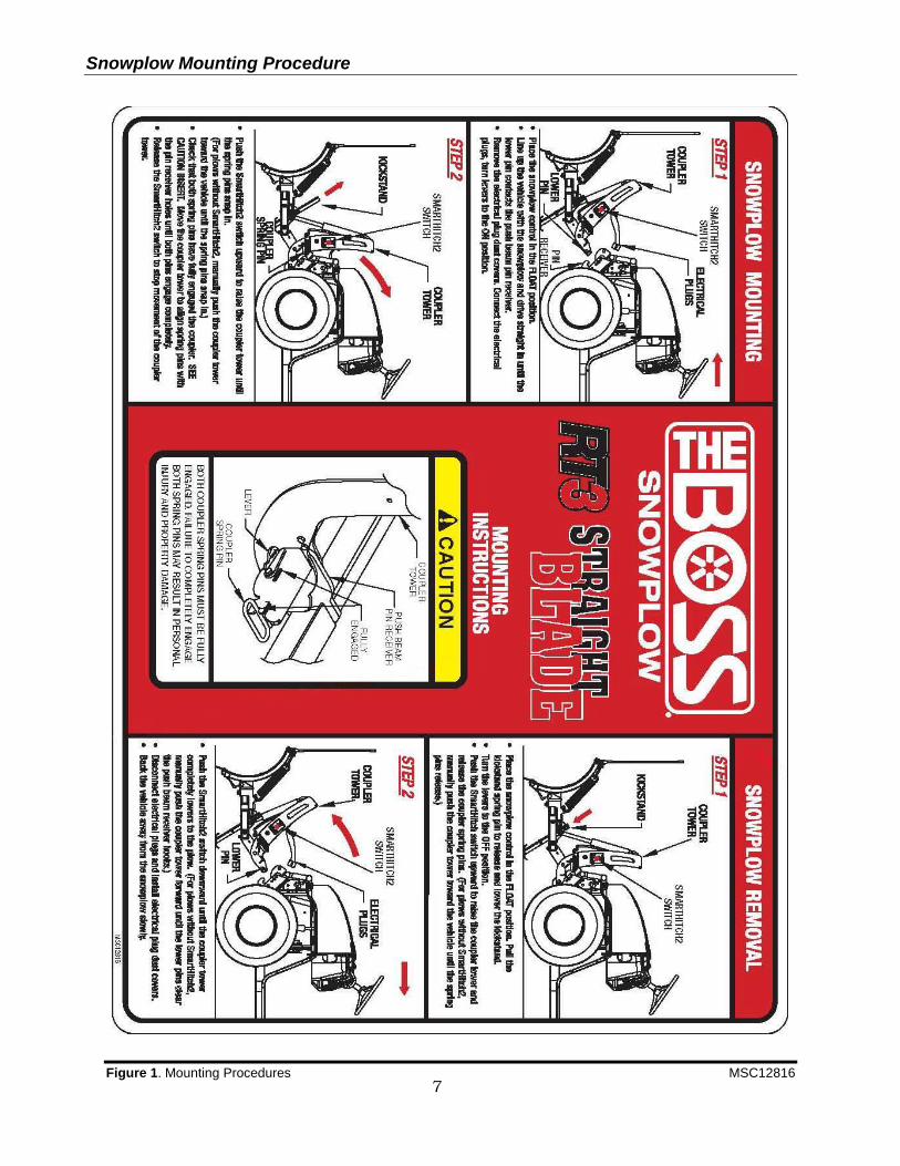
Snowplow Mounting Procedure
7
Figure 1. Mounting Procedures MSC12816
8
Maintenance
Your BOSS PLOW is designed for reliable service with minimal maintenance. To ensure that it gives you the same high performance year after year, please use it properly and observe the following maintenance precautions.
Inspect the following on a regular basis: All fasteners, pins, retainers, nuts and bolts for tightness. See Recommended Bolt Torque located in this manual.
All hydraulic lines and connections for wear and leakage.
Hydraulic cylinders for leakage, rods for rust or pitting.
Cutting edge wear.
Plow shoe wear.
Hydraulic oil level (CAUTION: DO NOT OVERFILL). Fill hydraulic pump reservoir as shown on page 24 using Boss High Performance Hydraulic Fluid or equivalent.
Control Harness and Power/Ground Cable Connectors for corrosion. Apply dielectric grease at least once a month during the plow season.
Apply grease to coupler spring pins and kickstand spring pin. Putting the Plow into Storage
1. Drive the snowplow to a storage site. Follow the normal procedure for dismounting from the plow. 2. Disconnect all electrical plugs and coat each connection with dielectric grease (lights, valve assembly, pump,
pump solenoid, and battery). Install all dust caps and plugs provided. 3. Touch-up any rust spots or chipped paint. 4. Loosen the trip springs. 5. Grease the coupler spring pins and kickstand spring pin. 6. Power the lift tower forward until the lift cylinder is completely compressed. This will protect the lift cylinder from
corrosion. 7. Grease the exposed chrome on the angling cylinders to protect from corrosion.
Taking the Plow out of Storage
1. Check all fasteners for tightness. See Recommended Bolt Torque located in this manual. 2. Check hydraulic hoses for cracks and leaks. 3. Check hydraulic oil level (CAUTION: DO NOT OVERFILL). Fill hydraulic pump reservoir as shown on page 24
using BOSS High Performance Hydraulic Fluid or equivalent. 4. Tighten the trip springs. 5. Coat each electrical connection with dielectric grease (lights, valve assembly, pump, pump solenoid and battery). 6. Grease the coupler spring pins and kickstand spring pin (Fig. 1).
Snowplow Assembly Procedure
9
Snowplow Assembly Procedure
Note: This manual is used for the assembly of the BOSS Sport Duty UTV Straight Blade Plow. Part numbers for the BOSS Sport Duty UTV Straight Blade plow are listed on the parts diagram in this manual.
Figure 2. Push Frame Attachment G10638
1. Attach Push Frame Attachment Bar (3) to Plow
Blade (4) using two HDW01706 5/8”-11 x 4” Hex Head Cap Screws (66) and two HDW01709 5/8”-11 Self-Locking Nuts (67).
Figure 3. Trip Spring Assembly G10639
2. Insert MSC01509 Trip Spring (39) through the
holes provided on Push Frame Attachment Bar (3).
3. Attach HDW02004 Spade Bolt (48) around the loose end of Trip Spring (39).
4. Insert the threaded end of Spade Bolt (48) through the hole in the spring mounting brackets on the back of Blade Assembly (4). Secure each Spade Bolt (48) with one HDW01729 ½” Flat Washer (41) and one HDW01748 Self Locking Nut (44). Tighten Self-Locking Nuts (43) until the coils on Trip Springs (39) are approximately 1/32" apart.
Figure 4. Lift Cylinder and Breather Installation G10640
5. Position the rod end of HYD07022 Lift Cylinder (12) between the cylinder mounts of Push Frame Assembly (2). Insert HDW05614 5/8” x 3 Clevis Pin (57) through the cylinder mounts and secure with HDW05544 #16 Hairpin Cotter (56).
6. Align the pivot holes of Coupler Assembly (1) with the pivot holes of Push Frame Assembly (2).
7. Insert 3/4” x 2” Pivot Pins (52A) through Coupler Assembly (1) and Push Frame Assembly (2). Place a 3/4” Flat Washer (52B) on 3/4” x 2” Pivot Pin (52A) then insert 3/16” x 2 ½” Cotter Pin (52C) through 3/4” x 2” Pivot Pin (52A). Spread the ends of 3/16” x 2 ½” Cotter Pin (52C).
Snowplow Assembly Procedure
10
8. Rotate Lift Cylinder (12) up to the cylinder mounts located on Coupler Tower Assembly (1). Insert 5/8” x 3 ½” Clevis Pin (57) through the cylinder mounts and secure with #16 Hair Pin Cotter (56).
9. Remove the plug from the top end of the Lift Cylinder (12).
10. Install Breather Vent (17) into top end of Lift Cylinder (12)
Figure 5. Hydraulic Connections G10641
11. Install HYD01620 90° Swivel (16) fitting into the lower port of Lift Cylinder (12).
12. Install HYD01695 ¼” x 15 ½” Hydraulic Hose (13) between the middle fitting on the hydraulic shelf and the 90° Swivel (16) installed in the previous step. Tighten both ends of the hose securely.
13. Install HYD01620 90° Fitting (16) into left Angle Cylinder (11). 90° Fitting (16) should be installed at a 45° angle forward.
14. Install HYD12825 Hydraulic Hose (15) between the left fitting on the hydraulic shelf and 90° Fitting (16) installed in the previous step. Tighten both ends of the hose securely.
15. Repeat steps 13-14 for the Right Angle Cylinder Hose.
Figure 6. Assembly of Blade Guides G10642
16. Attach Blade Guides (40) to Blade Assembly (4) using Hex Head Cap Screws (46), Self Locking Nuts (45), and Self-Tapping Hex Head Cap Screws (47).
Electrical System Installation Procedure
11
Figure 7. Internal Cab Wires G10495
1. Pull the 9 Pin Molex connector (G) from under the hood, into the cab.
2. Secure the 9 Pin Molex Connector (G) to the left of the steering wheel using two self tapping bolts and provided dash bracket. (Some vehicle use existing hardware. See figure 8)
Figure 8. Dash Bracket w/ Molex Plug & Cap G10526
3. Plug the controller into the 9 Pin Molex Connector (G).
4. Mount the plow control in a location that is comfortable for the operator to reach, and where the operator will not contact the control in the event of a crash. (See “Straight Blade Controller Mounting Instructions” located in this manual.)
5. Connect the BLACK/RED wire (I) to a “keyed” 12V+ ignition source on the vehicle. An example is pictured in Figure 9.
Figure 9. Keyed fuse source location G10525
Note: This 12V+ source should only be active when the key
is in the ON position. Failure to wire to a “keyed” source can allow a condition to occur causing the battery to drain.
Figure 10. Solenoid Connections. G10643
6. Connect the WHITE/BLACK wire (J) of Wiring Harness (21) to the small terminal on Pump Solenoid (23).
7. Connect the BROWN wire (K) of Wiring Harness (21) to the other small terminal on Pump Solenoid (23).
Note: Location of the wires on the small terminals does not
matter.
8. Attach Power Unit Solenoid (23) securely inside the under hood compartment. The Power Unit Solenoid should be mounted in the upright position as illustrated above. (See Figure 9)
Note: The solenoid must be installed so that the solenoid
posts do not contact the body or any other conductive material on the vehicle.
9. Attach the eyelet end of RED Power/Ground Cable (20) to the large post of Pump Solenoid (23). (See Figure 9)
10. Connect Battery Cable (24) to the other large post of Pump Solenoid (23). (See Figure 9)
Note: Location of the wires on the large terminals does not
matter. Note: Kubota, John Deere, and Kawasaki vehicles will
require Battery Cable Extension Kit. (MSC13171)
NOTICE:
Before splicing into any electrical circuit, identify the
circuit with a test lamp. Failure to test circuits may result in
vehicle damage.
Be sure the wire loom does not interfere with the operation
of the vehicle’s pedals.
Electrical System Installation Procedure
12
Figure 11. Battery Connections G10644
11. Attach the eyelet end (N) of BLACK Power/Ground Cable (20) to the negative battery terminal.
12. Connect the BROWN wire (Q) to the negative battery terminal.
13. Connect the unattached end (P) of Battery Cable (24) to the positive battery terminal.
14. Connect the RED Fused wire (O) to the positive
battery terminal.
Figure 12. Vehicle Connections G10148
15. Mount the Black 13 Pin Control Harness
Connector to the top tube of the bumper on the Driver’s Side using self-tapping bolts and MSC12815 Control Harness Mounting Bracket. (See Figures 12 & 13 for an example) Drilling is required.
13. Plug Location G10626
16. Mount the BLACK and RED 2 Pin Power Ground Connector to the MSC12815 Bracket using MSC03491 Power Ground Mounting Bracket.
17. Attach the Relay Pack securely under the hood using one HDW01766 Sheet Metal Screws. The relays should be positioned upright as illustrated in Figure 14.
14. Relay Mounting G10627
18. Secure all plow harness wiring using provided tie straps.
19. Attach the snowplow to the vehicle. Use the
“Snowplow Mounting Procedure” that is located in this manual to properly attach the snowplow to the vehicle.
NOTICE:
All plow wiring should be secured under the hood in a
position that provides sufficient room so that hot or moving
parts will not be contacted. Vehicle damage could occur if
wires are not properly secured.
Electrical System Wiring Diagram
13
Figure 15. Electrical System Wiring Diagram G10645
-poster page-
14
-poster page-
15
Electrical System Wiring Schematic (Plow Side)
16
Figure 16. Electrical System Wiring Schematic (Plow Side) G10497
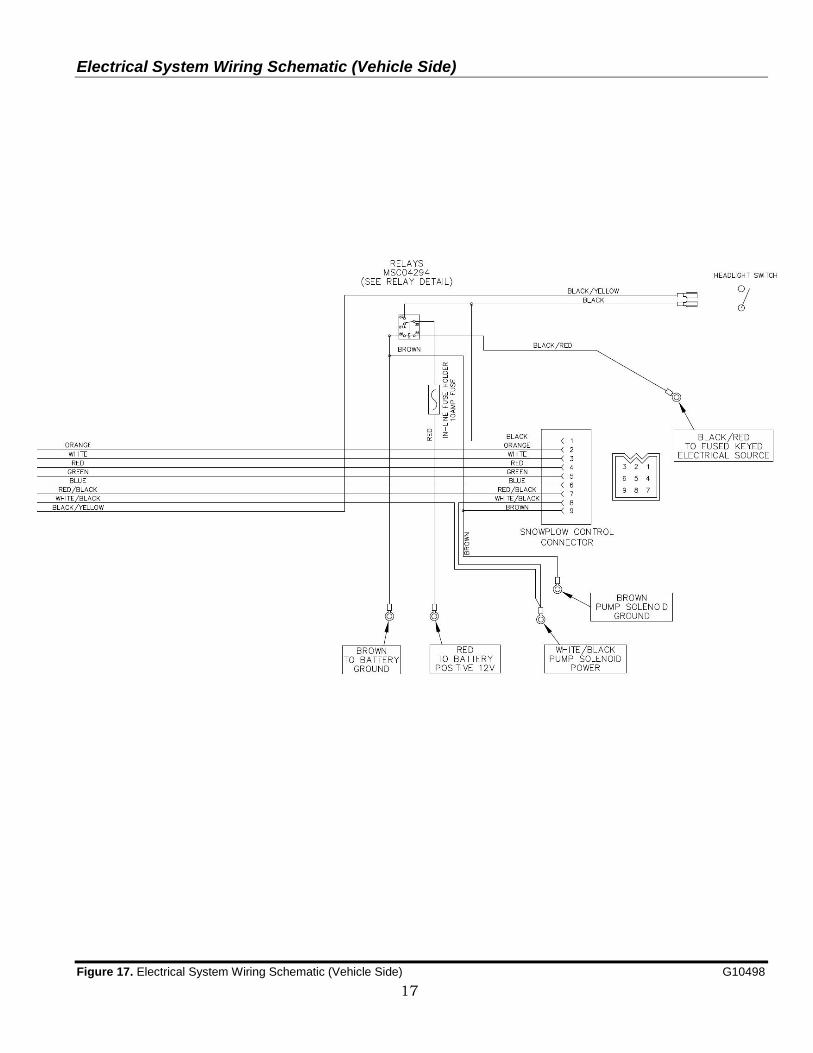
Electrical System Wiring Schematic (Vehicle Side)
17
Figure 17. Electrical System Wiring Schematic (Vehicle Side) G10498
RT3 Straight Blade Manifold Wiring Diagrams
18
Figure 18. HYD12270 UTV Sport Duty Manifold Wiring Diagram G10447
Wire Color Wire Function Green Blade Left
Red Blade Right
White Lift
Orange Lower
Red/Black Blade Right
Blue Blade Left
Black SmartHitch2TM (12V) (Optional)
Brown Ground
Black/Yellow Headlight Harness (If equipped)
Hydraulic Power Unit Fill Procedure
19
Hydraulic Power Unit Fill
Procedure
Figure 19. External Fill – Backside View G10625
Step 1 of the following fill procedure is intended for a new plow with an empty hydraulic system. Initial Plow Position: Start with the plow un-attached from the vehicle and the lift cylinder completely collapsed. The light tower will be tilted forwarded.
1. Remove HYD04810 Fill Cap (9C) from HYD04809 Street Elbow (9D) and fill with Boss High Performance Hydraulic Fluid. Continue to fill Street Elbow (9D) until no more fluid will be accepted. (Approx. 2 quarts.)
2. Attach the plow to the vehicle. Note: If plow is equipped with SmartHitch2™ you must hydraulically power the light tower up. Do not manually push the tower up. Failure to hydraulically power the light tower up will create an air pocket in the hydraulic system. Oil will spill out of your internal filler cap.
3. Raise the plow.
4. With the plow in the raised position, cycle through both angle functions several times.
5. Lower the plow to the ground.
Figure 20. Oil Full Level G00000
Plow Position to Check Oil: The plow should be attached to the vehicle, sitting flat on the ground, with the blade in the straight position.
6. With the blade in the straight position and the plow lowered to the ground, check the fluid level. Fluid should be visible in the external fill port. If fluid is not visible, fill until visible. Your reservoir should now be properly filled.
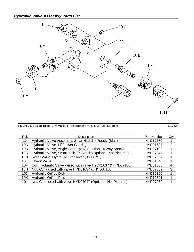
10L Nut, Coil - used with valve HYD07047 (Optional, Not Pictured) HYD07060 1
Straight Blade Controller
21
SmartTouchTM Control
Operating Instructions
Figure 22. Straight Blade Control Instructions G00000
1. Slide the ON/OFF switch to the right to turn the
Handheld Control on. Green LED indicators will light up on the control.
2. To RAISE or LOWER the blade of the plow, press the center button to the desired position.
3. Holding the LOWER button for 2 seconds will activate the Automatic “FLOAT” feature. (The center LED indicator will turn RED.)
Note: The FLOAT feature allows the plow blade to mirror the contour of the ground. Note: Press the raise button to turn the FLOAT function off.
4. Pressing the Angle Left button will swing the plow to the left, pushing snow to the left.
5. Pressing the Angle Right button will swing the plow to the right, pushing snow to the right.
6. The control should be turned off when not in use. It can then be unplugged and stored.
SmartTouchTM Control
Mounting Instructions
Figure 23. SmartTouchTM Mounting Hardware G10311
1. Remove the Swivel Mount and Tab from the MSC05058 Swivel Mount Kit.
2. Use the enclosed alcohol wipe to clean a spot on the vehicle interior where you want to place the SmartTouchTM Control. Wipe dry immediately with a cloth or paper towel.
3. Do not apply when the surface temperatures are lower than +60˚F (Working temperature range of the adhesive is -40˚F to +200˚F).
4. Peel off the paper backing on one side of the adhesive and apply to Swivel Mount. Apply maximum pressure to all areas.
5. Apply the Swivel Mount onto the spot of the interior that was just cleaned. (MAKE SURE IT IS IN THE CORRECT PLACE) Once it is placed it cannot be removed without destroying the adhesive.
6. Clean the back of the SmartTouchTM Control with the alcohol wipe.
7. Peel off adhesive backing of tape, apply to Tab, and press firmly.
8. Remove remaining backing and apply the Tab to the back of the SmartTouchTM Control. Apply pressure for 30 seconds.
NOTICE After attaching the Swivel Mount, let it sit unused for 72 hours before attaching the SmartTouchTM
Control to allow the adhesive to bond to the surface and insure secure mounting.
9. Place SmartTouchTM Control on the Swivel Mount.
ON/OFF SWITCH
ANGLE LEFT
ANGLE RIGHT
BLADE RAISE/LOWER
SWIVEL
MOUNT TAB
Troubleshooting Guide
22
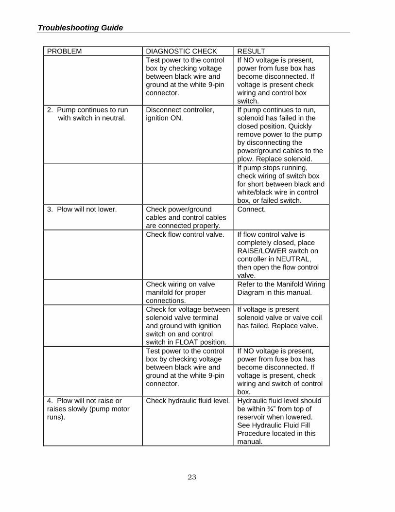
Troubleshooting Guide Glossary of Problems: 1. Pump motor does not run. 2. Pump continues to run with switch in neutral. 3. Plow will not lower. 4. Plow will not raise or raises slowly, motor runs. 5. Blade Angles While Plowing Snow 6. Blade will not angle, but motor runs. 7. Blade angles too easily while plowing. 8. Oil leaks from cylinders. 9. Battery goes dead with all switches in neutral. 10. Plow does not clean-up snow from low areas. 11. Oil runs out of fill cap of hydraulic pump. 12. Pump chatters when raising the plow or angling blade. 13. SmartHitch2TM will not attach plow.
PROBLEM DIAGNOSTIC CHECK RESULT
1. Pump motor does not run.
Check power/ground cables and control cables are connected properly.
Connect.
Check for voltage at pump motor while ignition switch is on and LIFT control button is pushed.
If voltage is present, pump motor has failed or pump has seized. Motor brushes may be replaced, otherwise replace pump/motor assembly.
Check for power to the solenoid by testing for voltage between both large terminals and ground.
If voltage is not present between one large terminal and ground, the cable between the battery and solenoid is disconnected or broken.
Check for voltage between the other large terminal of the solenoid and ground while jumping power to the small terminals with the white wire.
If NO voltage is present, solenoid has failed and must be replaced. If voltage is present, wire from small terminal of solenoid to ground may be disconnected or broken.
Troubleshooting Guide
23
PROBLEM DIAGNOSTIC CHECK RESULT
Test power to the control box by checking voltage between black wire and ground at the white 9-pin connector.
If NO voltage is present, power from fuse box has become disconnected. If voltage is present check wiring and control box switch.
2. Pump continues to run with switch in neutral.
Disconnect controller, ignition ON.
If pump continues to run, solenoid has failed in the closed position. Quickly remove power to the pump by disconnecting the power/ground cables to the plow. Replace solenoid.
If pump stops running, check wiring of switch box for short between black and white/black wire in control box, or failed switch.
3. Plow will not lower. Check power/ground cables and control cables are connected properly.
Connect.
Check flow control valve. If flow control valve is completely closed, place RAISE/LOWER switch on controller in NEUTRAL, then open the flow control valve.
Check wiring on valve manifold for proper connections.
Refer to the Manifold Wiring Diagram in this manual.
Check for voltage between solenoid valve terminal and ground with ignition switch on and control switch in FLOAT position.
If voltage is present solenoid valve or valve coil has failed. Replace valve.
Test power to the control box by checking voltage between black wire and ground at the white 9-pin connector.
If NO voltage is present, power from fuse box has become disconnected. If voltage is present, check wiring and switch of control box.
4. Plow will not raise or raises slowly (pump motor runs).
Check hydraulic fluid level. Hydraulic fluid level should be within ¾” from top of reservoir when lowered. See Hydraulic Fluid Fill Procedure located in this manual.
Troubleshooting Guide
24
PROBLEM DIAGNOSTIC CHECK RESULT
Check that power/ground cables and control cable are connected properly.
Connect.
Check wiring on valve manifold for proper connections.
Refer to the Manifold Wiring Diagram in this manual.
Load test battery. Replace battery if weak or defective.
Check pressure at pressure port of pump.
If pressure is less than 2500 psi (at end of lift). Motor brushes may be defective, pump pressure relief valve may be contaminated, damaged, or set less than 2500 psi, pump may be worn.
Check LIFT Solenoid Valve
Lift solenoid valve not opening completely. Replace.
Check wiring and controller.
5. Blade angles while plowing snow.
Check angle solenoid valve on manifold Check pressure
If solenoid valve is contaminated, clean or replace. If pressure relief valve is contaminated, clean or replace.
6. Blade will not angle or angles slowly, motor runs.
Check hydraulic fluid level. Hydraulic fluid level should be within ¾” from top of reservoir when lowered. See Hydraulic Fluid Fill Procedure located in this manual.
Check power/ground cables and control cable are connected properly.
Connect.
Check wiring on valve manifold for proper connections.
Refer to the Manifold Wiring Diagram in this manual.
Load test battery. Replace battery if weak or defective.
25
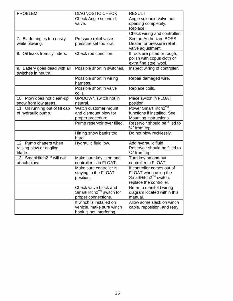
PROBLEM DIAGNOSTIC CHECK RESULT
Check Angle solenoid valve.
Angle solenoid valve not opening completely. Replace.
Check wiring and controller.
7. Blade angles too easily while plowing.
Pressure relief valve pressure set too low.
See an Authorized BOSS Dealer for pressure relief valve adjustment.
8. Oil leaks from cylinders. Check rod condition. If rods are pitted or rough, polish with copus cloth or extra fine steel wool.
9. Battery goes dead with all switches in neutral.
Possible short in switches. Inspect wiring of controller.
Possible short in wiring harness.
Repair damaged wire.
Possible short in valve coils.
Replace coils.
10. Plow does not clean-up snow from low areas.
UP/DOWN switch not in neutral.
Place switch in FLOAT position.
11. Oil running out of fill cap of hydraulic pump.
Watch customer mount and dismount plow for proper procedure.
Power SmartHitch2TM functions if installed. See Mounting instructions.
Pump reservoir over filled. Reservoir should be filled to ¾” from top.
Hitting snow banks too hard.
Do not plow recklessly.
12. Pump chatters when raising plow or angling blade.
Hydraulic fluid low. Add hydraulic fluid. Reservoir should be filled to ¾” from top.
13. SmartHitch2TM will not attach plow.
Make sure key is on and controller is in FLOAT.
Turn key on and put controller in FLOAT.
Make sure controller is staying in the FLOAT position.
If controller comes out of FLOAT when using the SmartHitch2TM switch, replace the controller.
Check valve block and SmartHitch2TM switch for proper connections.
Refer to manifold wiring diagram located within this manual.
If winch is installed on vehicle, make sure winch hook is not interfering.
Allow some slack on winch cable, reposition, and retry.
26
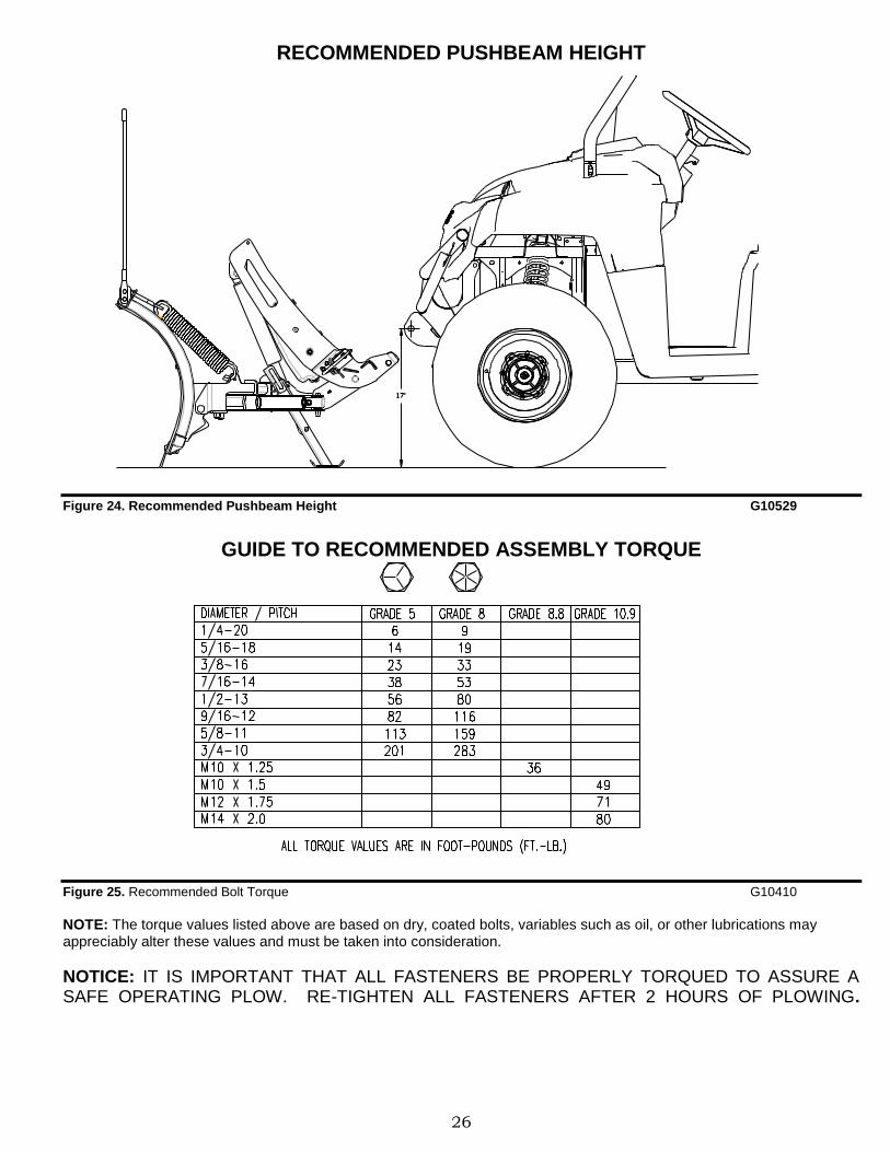
RECOMMENDED PUSHBEAM HEIGHT
Figure 24. Recommended Pushbeam Height G10529
GUIDE TO RECOMMENDED ASSEMBLY TORQUE
Figure 25. Recommended Bolt Torque G10410
NOTE: The torque values listed above are based on dry, coated bolts, variables such as oil, or other lubrications may appreciably alter these values and must be taken into consideration.
NOTICE: IT IS IMPORTANT THAT ALL FASTENERS BE PROPERLY TORQUED TO ASSURE A SAFE OPERATING PLOW. RE-TIGHTEN ALL FASTENERS AFTER 2 HOURS OF PLOWING.
27
BOSS SNOWPLOW
COMMERCIAL WARRANTY
What this warranty covers: This warranty covers defects in material and workmanship except as set forth below. Who is covered: The original purchaser from an authorized dealer. For how long: Parts: 2 years from the date of purchase. Labor: 2 years from the date of purchase. What BOSS PRODUCTS will do: BOSS PRODUCTS will, at its sole option, repair or replace defective parts at no charge. What you must do to for warranty service: To obtain warranty service, purchaser must return the defective snowplow to any authorized BOSS PRODUCTS dealer (preferably the one from whom the snowplow was purchased) within the warranty period. Purchaser must be able to verify the original purchase date. All transportation costs to and from the dealer will be the responsibility of the purchaser. To locate the authorized BOSS dealer nearest to you, call toll free: (800) 286-4155. What is not covered: This warranty does not cover: 1. Expendable parts such as hoses, plow shoes, cutting edges, pins, nuts, bolts, blade guides, etc. 2. Snowplows or parts repaired or altered by anyone other than an authorized BOSS PRODUCTS dealer. 3. Snowplows or parts which have been subject to misuse, negligence, accident, improper installation, maintenance, care or
storage. 4. Snowplows mounted on vehicles other than those listed in the BOSS SNOWPLOW APPLICATION CHART AND
SELECTION GUIDE. 5. BOSS PRODUCTS does not assume liability for damage to your motor vehicle resulting from the attachment or use of a BOSS
PRODUCTS snowplow. Vehicle risk is the sole responsibility of the purchaser. Limits of BOSS Products Liability are: BOSS PRODUCT’S LIABILITY IS EXPRESSLY LIMITED TO REPAIR OR REPLACEMENT OF DEFECTIVE PARTS. BOSS PRODUCTS SHALL NOT BE LIABLE FOR CONSEQUENTIAL, INCIDENTAL OR CONTINGENT DAMAGES WHATSOEVER, EVEN IF DAMAGES ARE CAUSED BY THE NEGLIGENCE OR FAULT OF BOSS PRODUCTS. THE FOREGOING WARRANTIES ARE EXCLUSIVE AND IN LIEU OF ALL OTHER EXPRESS AND IMPLIED WARRANTIES INCLUDING, BUT NOT LIMITED TO, THE IMPLIED WARRANTIES OF MERCHANTABILITY AND FITNESS FOR A PARTICULAR PURPOSE. This warranty does not apply if you purchased your snowplow for personal, family, or household use. In this case, refer to the BOSS Snowplow Limited Consumer Warranty.
BOSS PRODUCTS is a division of Northern Star Industries, Inc. PO Box 787 North U.S. Hwy 2
(2010-2011) Iron Mountain, MI 49801
28
BOSS SNOWPLOW LIMITED
CONSUMER WARRANTY What the warranty covers: BOSS PRODUCTS warrants to the original retail purchaser of a BOSS snowplow who purchases it for personal, family or household use, that the snowplow will be free from defects in material and workmanship except as set forth below. Warranty period: Parts: 2 years from the date of purchase. Labor: 2 years from the date of purchase. What BOSS PRODUCTS will do: If, within the warranty period, the snowplow is found to be defective, BOSS PRODUCTS will repair or replace, at its sole option, the defective parts at no charge to the original purchaser. What you must do for warranty service: To obtain service under this warranty, purchaser must return the defective snowplow to an authorized BOSS PRODUCTS dealer (preferably the one from whom the snowplow was purchased). The purchaser must establish the warranty period by verifying the original purchased date. All transportation costs to and from the dealer will be the responsibility of the purchaser. To locate the authorized BOSS dealer nearest to you, call toll free: (800) 286-4155. What is not covered: This limited warranty does not cover the following: 1. Expendable parts such as hoses, plow shoes, cutting edges, pins, nuts, bolts, blade guides, etc. 2. Snowplows or parts repaired or altered by anyone other than an authorized BOSS PRODUCTS dealer. 3. Snowplows or parts which have been subject to misuse or service, negligence, accident, improper installation,
maintenance, care or storage. 4. Snowplows mounted on vehicles other than those listed in the BOSS SNOWPLOW APPLICATION CHART AND
SELECTION GUIDE. 5. BOSS PRODUCTS does not assume any liability for motor vehicle damage resulting from the attachment or use of a
BOSS PRODUCTS snowplow. Vehicle risk is the sole responsibility of the purchaser. Warranty limitations: THIS WARRANTY IS OFFERED IN LIEU OF ANY OTHER EXPRESS WARRANTY. THE DURATION OF ALL IMPLIED WARRANTIES, INCLUDING BUT NOT LIMITED TO THE IMPLIED WARRANTIES OF MERCHANTABILITY AND FITNESS FOR A PARTICULAR PURPOSE, ARE LIMITED TO THE DURATION OF THIS WARRANTY. BOSS PRODUCTS LIABILITY IS EXPRESSLY LIMITED TO THE REPAIR OF THE SNOWPLOW, INCLUDING LABOR AND REPLACEMENT OF DEFECTIVE PARTS. BOSS PRODUCTS SHALL NOT BE LIABLE FOR ANY CONSEQUENTIAL, INCIDENTAL OR CONTINGENT DAMAGES WHATSOEVER, EVEN IF DAMAGES ARE CAUSED BY BOSS PRODUCTS NEGLIGENCE OR FAULT. State laws: Some states do not allow exclusion of incidental or consequential damages or the limitations on how long an implied warranty lasts, so these limitations or exclusions may not apply to you. This warranty gives you specific legal rights and you may also have the other rights which vary from state to state. This warranty does not apply if you purchased your snowplow for other than personal, family, or household use. If so, refer to the BOSS Snowplow Commercial Warranty.
BOSS PRODUCTS is a division of Northern Star Industries, Inc. PO Box 787 North U.S. Hwy 2