28
Applications Engineering RTA-FOUSB-MON User’s Manual Rev 2.2 Jan 2005 !"!"
| Date post: | 07-Apr-2018 |
| Category: |
Documents |
| Upload: | conduraru-alina |
| View: | 227 times |
| Download: | 0 times |
8/3/2019 Rta Fousb Mon Users Manual
http://slidepdf.com/reader/full/rta-fousb-mon-users-manual 1/28
Applications Engineering
RTA-FOUSB-MON User’s Manual Rev 2.2 Jan 2005
!"!"

8/3/2019 Rta Fousb Mon Users Manual
http://slidepdf.com/reader/full/rta-fousb-mon-users-manual 2/28
Applications Engineering
RTA-FOUSB-MON User’s Manual Rev 2.2 1 / 27 Jan 2005
Table of Contents
1. Kit Overview.………………………………………………………………………………2
2. Software Installation …………………………………………………………………….3
3. Driver Installation.………………………………………………………………………..3
4. Running KD30 Debugger ……………………………………………………………….5
5. Running FoUSB Programmer ………………………………………………………….6
6. Target Hardware Connectivity for In-System Programming………………………9
7. Target Hardware Connectivity for In-Circuit Debugging..………………………...13
8. Target MCU Resources Used by the ICD for Debugging……………..…………..17
Appendix A. ICD Specifications.………….………………………………………………19
Appendix B. Technical Notes & Limitations ...…………………………………………20
Appendix C. Troubleshooting …………………………………………………………….21
Appendix D. Reference Manuals..………………………………………………………...26
Appendix E. Board Schematic & BOM……..…………………………………………….27

8/3/2019 Rta Fousb Mon Users Manual
http://slidepdf.com/reader/full/rta-fousb-mon-users-manual 3/28
Applications Engineering
RTA-FOUSB-MON User’s Manual Rev 2.2 2 / 27 Jan 2005
Fig. 1.1 RTA-FoUSB-MON (ICD)
1. Kit Overview
The RTA-FoUSB-MON (ICD) is a low cost compact device that can function as an In-Circuit Debugger(ICD) tool or as an FoUSB (Flash-over-USB
TM) Programmer for Renesas M16C Flash microcontrollers
(MCU). KD30 and KD3083 are the software applications for debugging M16C and M32C firmware andFoUSB Programmer is the software application for programming the Renesas M16C Flash MCU’s.
Here are some of the ICD highlights:
• M37641F8HP (8-bit USB Renesas MCU) with 3.9KB RAM and 32KB Flash ROM.
• Bus-powered (powered by USB) or target-powered selectable. No external power supplyneeded when connecting to Renesas’ SKP’s (Starter Kits).
• Target connection through a 10-pin header with matching 6 in. cable.• Mini-USB connector with matching 6ft cable to connect to host PC.
• Semtech USB upstream port filter, EMI, and ESD protection circuitry. All in one devicereduces target system part count and complexity while provides internal circuit protection.
• Works on Windows XP, 2000, Windows ME, and Windows 98.
Package Contents:
• 1 – In-Circuit Debugger (ICD)
• 1 – 6ft USB Cable
• 1 – 6 in. 10-pin Flat Cable
• 1 – CD ROM (Documentation, FoUSB Programmer, Debugger)
LED’s:STOP (red) – Target StoppedRUN (green) – Target RunningSTATUS (yellow) – ICD Status
POWER (red) – Power
Mini USB
Connector
Bus or TargetPowered Switch
10-Pin Connector toTarget

8/3/2019 Rta Fousb Mon Users Manual
http://slidepdf.com/reader/full/rta-fousb-mon-users-manual 4/28
Applications Engineering
RTA-FOUSB-MON User’s Manual Rev 2.2 3 / 27 Jan 2005
2. Software Installation
Before using the ICD, we need to install the required software files and applications. Do not plug the ICDinto your PC until the install process is finished.
2.1 Insert the enclosed “RTA-FoUSB-MON” CD ROM in the PC’s CD Rom drive.
2.2 The CD should auto start and the Renesas Starter Kit Plus welcome screen is displayed. Ifthe screen does not come up, browse the root folder of the CD using Windows Explorer anddouble-click on ‘SKP_Installer.exe ’.
2.3 The installer will create a new directory C:\MTOOL\RTA-FOUSB-MON on your PC where itwill copy the necessary files for the ICD. During the installation process, dialog boxes willappear allowing you to install the development tools and files. The installer for FoUSB v2.04(or later) will also automatically load the Windows system with the correct location of the USBdrivers for the FoUSB GUI.
2.4 After installation, please review the Quick Start Guide, which may contain information aboutthe ICD not yet available when this user’s manual was published.
2.5 Click on “Finish” to exit install program.
If you experience problems with the install software, please see C.1 Installing Required Files Manually in
Appendix C. Troubleshooting.
3. Driver Installation
Before using the ICD the device drivers need to be installed.
There are two USB drivers for Flash-Over-USB devices. They are:USBMON.SYS This is the USB driver that is used for the RTA-FoUSB-MON hardware. Note: In
Japan it is called the USB Flash Writer (M3A-0665).FOUSB.SYS This is the USB driver that is used for direct-connected MCU+USB devices operating
in boot-mode.
The driver files (.sys and .inf) are always located under the FoUSB install directory (For example:C:\MTOOL\FoUSB\USB Drivers\) in case you are have trouble with the automatic driver installer.
First, verify that the Power Mode switch (S1) on the ICD is in the USB (Bus powered) position. Nextconnect the ICD to your PC using the supplied USB cable.
If you are running Windows 98, ME or 2000, no intervention by the user is needed. When the ICD isplugged in, Windows automatically attaches the correct driver for your device and it is ready to use.
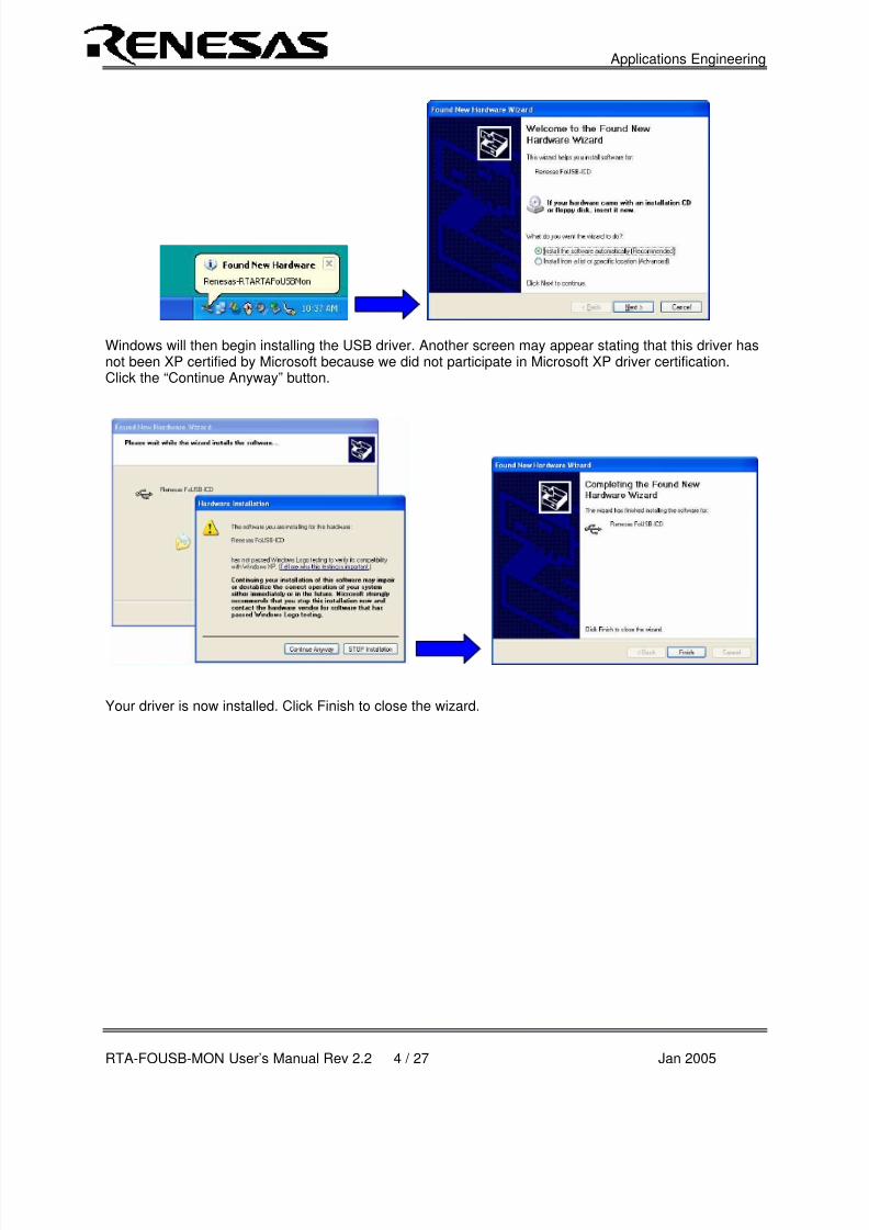
If you are running Windows XP, the first time an FoUSB device is plugged into a different USB port on thePC, the Windows XP “Found New Hardware Wizard” window will appear. Select the default option “Installthe software automatically (Recommended)” as seen below.
8/3/2019 Rta Fousb Mon Users Manual
http://slidepdf.com/reader/full/rta-fousb-mon-users-manual 5/28
Applications Engineering
RTA-FOUSB-MON User’s Manual Rev 2.2 4 / 27 Jan 2005
Windows will then begin installing the USB driver. Another screen may appear stating that this driver hasnot been XP certified by Microsoft because we did not participate in Microsoft XP driver certification.Click the “Continue Anyway” button.
Your driver is now installed. Click Finish to close the wizard.
8/3/2019 Rta Fousb Mon Users Manual
http://slidepdf.com/reader/full/rta-fousb-mon-users-manual 6/28
Applications Engineering
RTA-FOUSB-MON User’s Manual Rev 2.2 5 / 27 Jan 2005
4. Running KD30 Debugger
Before running the debugger, connect the target board to the ICD using the 10-pin flat ribbon cable.Connect the ICD to your PC using the supplied USB cable. If you are using a Renesas SKP starter kit(e.g.: SKP16C62P) the ICD should be set to Bus Powered (S1 set to USB) mode. If using any othertarget board, select Target Powered mode and supply power through the target board itself.
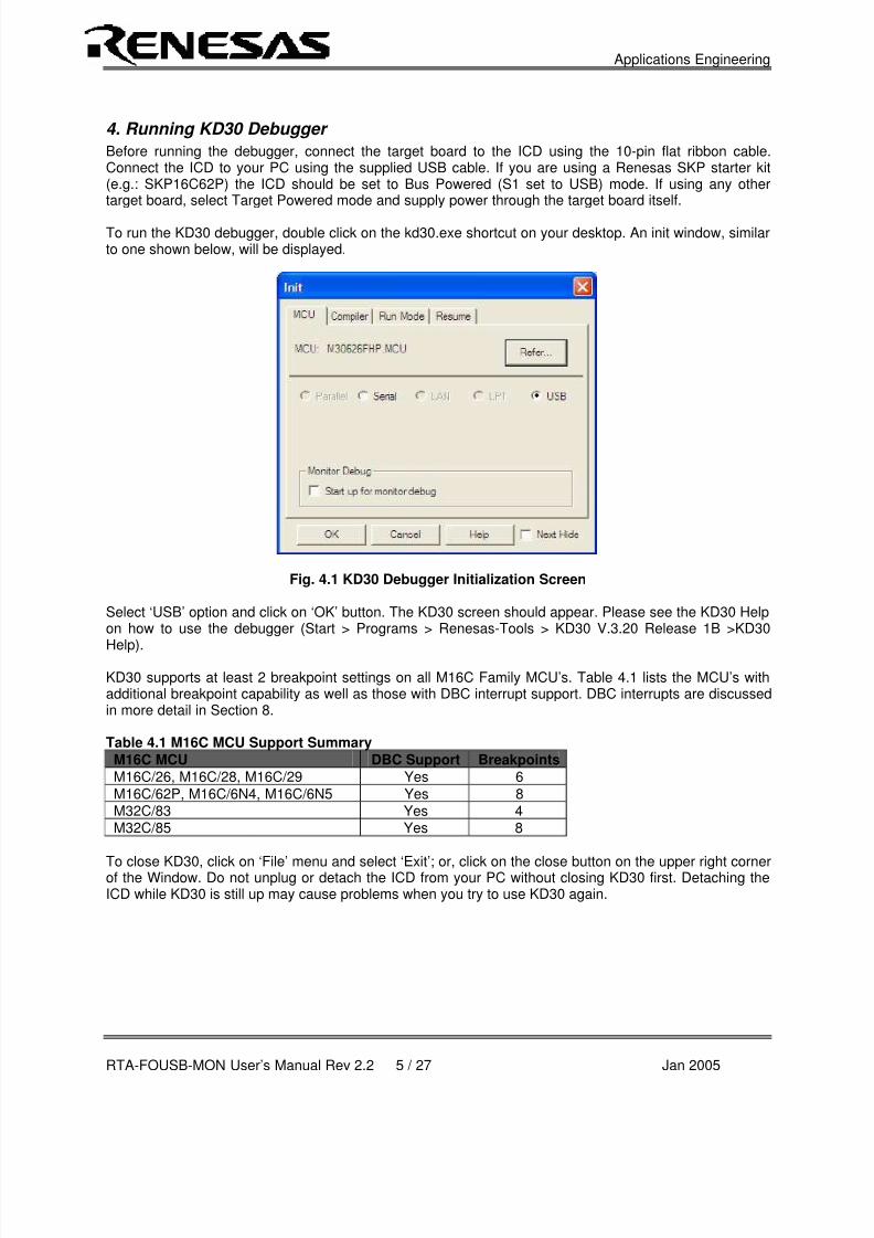
To run the KD30 debugger, double click on the kd30.exe shortcut on your desktop. An init window, similarto one shown below, will be displayed.
Fig. 4.1 KD30 Debugger Initialization Screen
Select ‘USB’ option and click on ‘OK’ button. The KD30 screen should appear. Please see the KD30 Helpon how to use the debugger (Start > Programs > Renesas-Tools > KD30 V.3.20 Release 1B >KD30
Help).
KD30 supports at least 2 breakpoint settings on all M16C Family MCU’s. Table 4.1 lists the MCU’s withadditional breakpoint capability as well as those with DBC interrupt support. DBC interrupts are discussedin more detail in Section 8.
Table 4.1 M16C MCU Support Summary M16C MCU DBC Support Breakpoints
M16C/26, M16C/28, M16C/29 Yes 6
M16C/62P, M16C/6N4, M16C/6N5 Yes 8M32C/83 Yes 4M32C/85 Yes 8
To close KD30, click on ‘File’ menu and select ‘Exit’; or, click on the close button on the upper right cornerof the Window. Do not unplug or detach the ICD from your PC without closing KD30 first. Detaching theICD while KD30 is still up may cause problems when you try to use KD30 again.
8/3/2019 Rta Fousb Mon Users Manual
http://slidepdf.com/reader/full/rta-fousb-mon-users-manual 7/28
Applications Engineering
RTA-FOUSB-MON User’s Manual Rev 2.2 6 / 27 Jan 2005
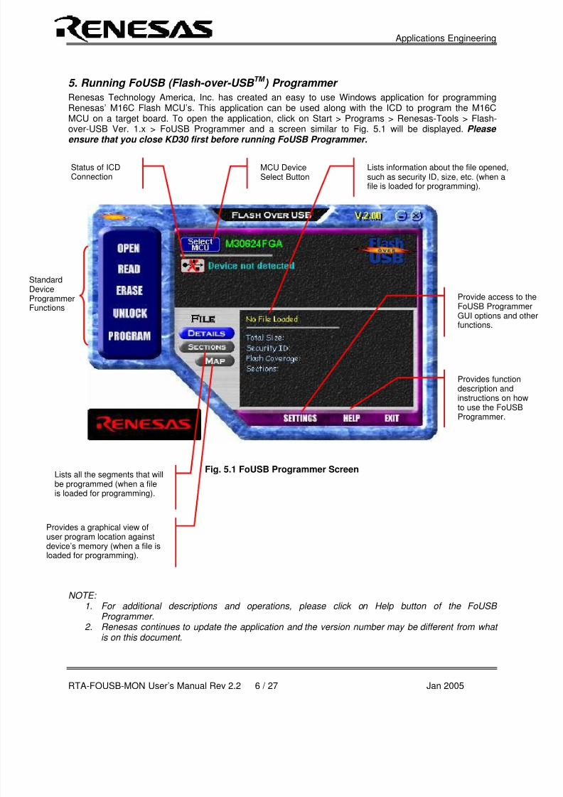
5. Running FoUSB (Flash-over-USB TM ) Programmer
Renesas Technology America, Inc. has created an easy to use Windows application for programmingRenesas’ M16C Flash MCU’s. This application can be used along with the ICD to program the M16CMCU on a target board. To open the application, click on Start > Programs > Renesas-Tools > Flash-over-USB Ver. 1.x > FoUSB Programmer and a screen similar to Fig. 5.1 will be displayed. Please
ensure that you close KD30 first before running FoUSB Programmer.
Fig. 5.1 FoUSB Programmer Screen
NOTE: 1. For additional descriptions and operations, please click on Help button of the FoUSB
Programmer.2. Renesas continues to update the application and the version number may be different from what
is on this document.
MCU DeviceSelect Button
StandardDeviceProgrammerFunctions
Status of ICDConnection
Provide access to tFoUSB ProgrammeGUI options and otfunctions.
Provides a graphical view ofuser program location againstdevice’s memory (when a file is
loaded for programming).
Lists all the segments that willbe programmed (when a fileis loaded for programming).
Lists information about the file opened,such as security ID, size, etc. (when afile is loaded for programming).
Provides functiondescription andinstructions on howto use the FoUSB
Programmer.
8/3/2019 Rta Fousb Mon Users Manual
http://slidepdf.com/reader/full/rta-fousb-mon-users-manual 8/28
Applications Engineering
RTA-FOUSB-MON User’s Manual Rev 2.2 7 / 27 Jan 2005
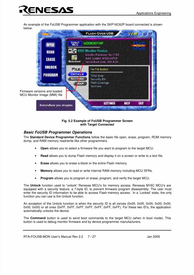
An example of the FoUSB Programmer application with the SKP16C62P board connected is shownbelow.
Fig. 5.2 Example of FoUSB Programmer Screenwith Target Connected
Basic FoUSB Programmer Operations
The Standard Device Programmer Functions follow the basic file open, erase, program, ROM memorydump, and RAM memory read/write like other programmers.
• Open allows you to select a firmware file you want to program to the target MCU.
• Read allows you to dump Flash memory and display it on a screen or write to a text file.
• Erase allows you to erase a block or the entire Flash memory.
• Memory allows you to read or write internal RAM memory including MCU SFRs.
• Program allows you to program or erase, program, and verify the target MCU.
The Unlock function used to “unlock” Renesas MCU’s for memory access. Renesas M16C MCU’s areequipped with a security feature, a 7-byte ID, to prevent firmware program disassembly. The user must
enter the security ID information to be able to access Flash memory access. In a ‘Locked’ state, the onlyfunction you can use is the Unlock function.
An exception of the Unlock function is when the security ID is all zeroes (0x00, 0x00, 0x00, 0x00, 0x00,0x00, 0x00) or all ones (0xFF, 0xFF, 0xFF, 0xFF, 0xFF, 0xFF, 0xFF). For these two ID’s, the applicationautomatically unlocks the device.
The Command button is used to send boot commands to the target MCU (when in boot mode). Thisbutton is used to debug monitor firmware and by device programmer manufacturers.
Firmware versions and loaded
MCU Monitor Image (MMI) file
8/3/2019 Rta Fousb Mon Users Manual
http://slidepdf.com/reader/full/rta-fousb-mon-users-manual 9/28
Applications Engineering
RTA-FOUSB-MON User’s Manual Rev 2.2 8 / 27 Jan 2005
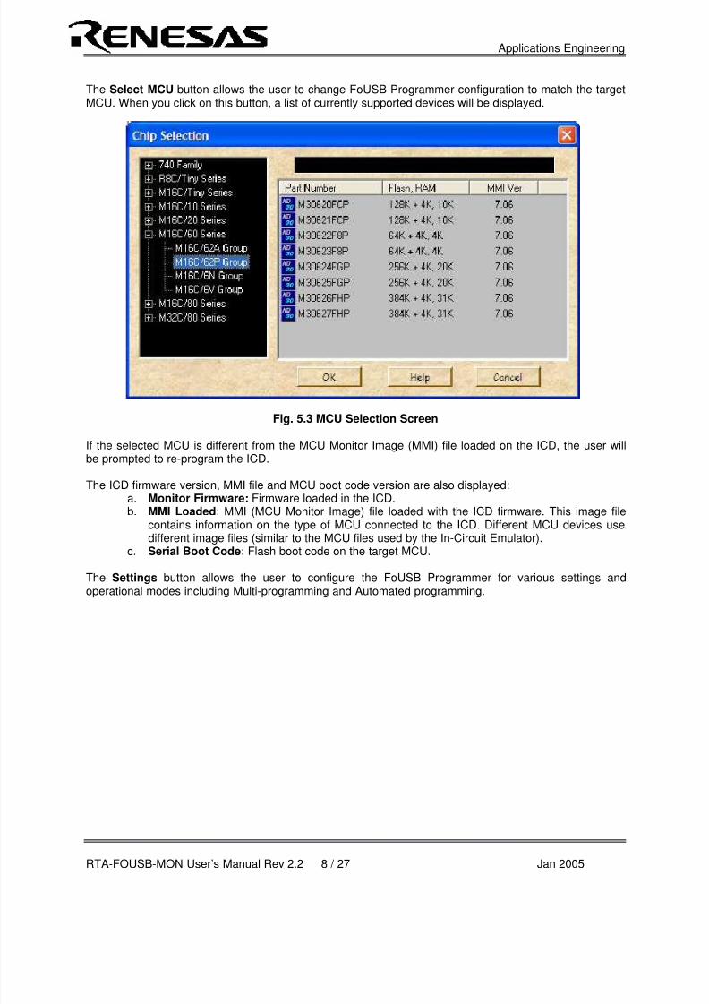
The Select MCU button allows the user to change FoUSB Programmer configuration to match the targetMCU. When you click on this button, a list of currently supported devices will be displayed.
Fig. 5.3 MCU Selection Screen
If the selected MCU is different from the MCU Monitor Image (MMI) file loaded on the ICD, the user willbe prompted to re-program the ICD.
The ICD firmware version, MMI file and MCU boot code version are also displayed:a. Monitor Firmware: Firmware loaded in the ICD.b. MMI Loaded: MMI (MCU Monitor Image) file loaded with the ICD firmware. This image file
contains information on the type of MCU connected to the ICD. Different MCU devices usedifferent image files (similar to the MCU files used by the In-Circuit Emulator).
c. Serial Boot Code: Flash boot code on the target MCU.
The Settings button allows the user to configure the FoUSB Programmer for various settings andoperational modes including Multi-programming and Automated programming.

8/3/2019 Rta Fousb Mon Users Manual
http://slidepdf.com/reader/full/rta-fousb-mon-users-manual 10/28
Applications Engineering
RTA-FOUSB-MON User’s Manual Rev 2.2 9 / 27 Jan 2005
1
3
5
7
9
2
4
6
8
10
Vcc
SCLK
CE
GND
CNVss
BUSY
RXD
EPM
RESET
TXD
6. Target Hardware Connectivity for In-System Programming
This section describes the hardware connections to the ICD for in-system programming purposes.Examples for different M16C MCU’s are shown at the end of the section.
The ICD connects to an M16C target board through a polarized, .100” (2.54mm), 10-pin connection using
a flat ribbon cable. It communicates with the M16C MCU using the boot UART/SIO in a clocked SIOconfiguration. The signals used and how these signals are assigned is described below.
Figure 6.1 Target Board 10-Pin Header/Connector Signal Assignment
NOTE: All target interface lines are in high impedance state until instructed to do otherwise by the FoUSB Programmer application.
1. Vcc – Power Supply PinThis provides the common connection point for power between ICD and the target board. This must beconnected to the target board’s Vcc line/plane.
In Target Power mode, the ICD requires at least 3.3V (5.0V max) and 50mA to operate properly.When programming target boards other than Renesas SKPs, set S1 to Target Powered mode and supplyexternal power.
2. Busy – Target MCU SIO Busy SignalThis line indicates whether the target is busy (and cannot receive data) or not. This must be connected tothe target MCU’s boot UART/SIO BUSY (CTS/RTS) pin.
This pin may be used for other applications as long as the user ensures that the ICD can drive the pin tovalid levels with 5mA current.
3. SCLK – Target MCU Serial Clock SignalThis clock is used for synchronous serial communication between ICD and target board. This must beconnected to the target MCU’s boot UART/SIO SCLK pin.
This pin may be used for other applications as long as the user ensures that the ICD can drive the pin tovalid levels with 5mA current.
4. RXD –Target MCU Receive Data Input Signal (ICD Transmit Data Output Signal)This is the ICD SIO transmit data output. This must be connected to the target MCU’s boot UART/SIOreceive data input (RXD) pin.
This pin may be used for other applications as long as the user ensures that the ICD can drive the pin tovalid levels with 5mA current.

8/3/2019 Rta Fousb Mon Users Manual
http://slidepdf.com/reader/full/rta-fousb-mon-users-manual 11/28
Applications Engineering
RTA-FOUSB-MON User’s Manual Rev 2.2 10 / 27 Jan 2005
5. CE PinThis pin is used to enter boot mode for programming of the target M16C MCU. Not all M16C MCU’s havea CE pin. If a CE pin exists on the target MCU, it should be connected to this pin (refer to serial modeflash programming in the target MCU’s datasheet). If not, leave pin unconnected.
If the target MCU’s CE pin is used as input, isolate the driving circuit from the header connection with a
1Kohm resistor.If to be left unconnected (if users decides to), care must be taken to ensure that the target MCU’s CE pinhas a high signal level using a pull-up resistor during any programming operations.
6. EPM Pin (in Target Power Mode)In Target Power Mode, the pin is used to control target MCU’s EPM pin (if it exists on the target MCU).EPM pin is used during programming of the target MCU. If this pin exists on the target MCU, it should beconnected to the header (refer to serial mode flash programming of the target MCU’s datasheet). If not,leave unconnected.
If the target MCU’s EPM pin is used as input, isolate the driving circuit from the header connection with a1Kohm resistor.
If the EPM pin of the M16C MCU is left unconnected (no external circuit and not connected to 10-pinheader), care must be taken to ensure that the target MCU’s EPM pin has a low signal level using a pull-down resistor during any programming operations.
7. GND – Ground PinThis provides the common point where the ICD ground and target board ground planes can beconnected. This must be connected to target board’s GND line/plane.
8. RESET – Target MCU Reset SignalThis active low signal is used by the ICD to reset the target MCU. This must be connected to the targetboard’s reset circuit or target MCU’s reset pin.
The user must ensure that the ICD can drive the pin to a valid low level with 5mA current.
9. CNVss – Target MCU CNVss PinThis active high signal is used by the ICD to control the target MCU’s CNVss pin for programmingpurposes. This must be connected to the target MCU’s CNVss pin. During normal operation, this pin musthave a low signal. To accomplish this, connect a 10K (nominal) pull-down resistor. See M16C MCUdatasheet on CNVss pin description for details.
10. TXD – Target MCU Transmit Data Output Signal (ICD Receive Data InputSignal)
This is the ICD SIO receive data input. This must be connected to the target M16C MCU’s bootUART/SIO transmit data output (TXD) pin.
This pin may be used for other applications as long as the user ensures that the ICD can drive the pin to
valid levels with 5mA current.

8/3/2019 Rta Fousb Mon Users Manual
http://slidepdf.com/reader/full/rta-fousb-mon-users-manual 12/28
Applications Engineering
RTA-FOUSB-MON User’s Manual Rev 2.2 11 / 27 Jan 2005
11. Hardware Summary and Precautions• Connect pull-down resistors to the CNVss line.
• Connect Reset line to the target MCU Reset pin or the target board’s reset circuit.
• If EPM or CE lines are used as input pins, isolate the driving circuit from the 10-pin header usinga 1Kohm resistor.
• If possible, avoid using the boot SIO/UART pins for other purposes. If not, ensure the lines can be
driven in boot mode.• The FoUSB Programming supports most M16C, M32C and R8C Flash MCU’s. See the FoUSB
GUI for specific MCUs.
Examples of target board hardware connections to the 10-pin header (ICD), when used for in-systemprogramming only, are shown below. If you cannot find your M16C Flash MCU in the examples shown,please contact Renesas representative for assistance.
VccP6_4/RTS1 (Busy)P6_5/CLK1 (SCLK )P6_6/RxD1 (RxD )P8_6/XCout (CE )
Vss!RESETCNVssP6_7/TxD1 (TxD )
M16C/26, M16C/28,M16C/29
10-Pin
Header Vcc
47K(nominal)
!RESET
123456789
10
BUSYVcc
CLKRxDCE
EPMGND
CNVssTxD
VccMODE (Busy)CNVss (SCLK )P3_7 (RxD1)
Vss!RESET
P0_0 (TxD1)
Vcc
47K(nominal)
R8C/10, R8C/11,R8C/12, R8C/13
47K
(nominal)
123456789
10
10-Pin
Header
EPM
BUSYVcc
CLKRxDCE**
GND
CNVssTxD
!RESET
8/3/2019 Rta Fousb Mon Users Manual
http://slidepdf.com/reader/full/rta-fousb-mon-users-manual 13/28
Applications Engineering
RTA-FOUSB-MON User’s Manual Rev 2.2 12 / 27 Jan 2005
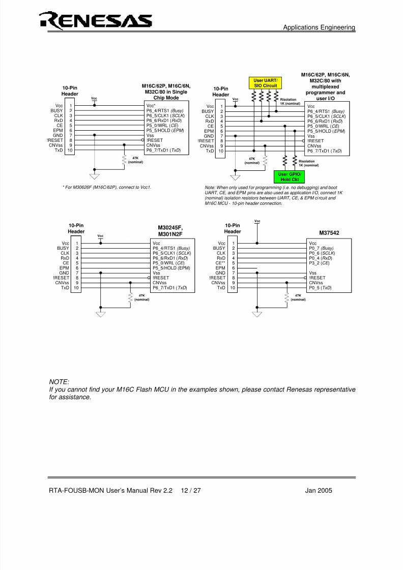
NOTE: If you cannot find your M16C Flash MCU in the examples shown, please contact Renesas representative
for assistance.
EPM
123456789
10
VccP6_4/RTS1 (Busy)P6_5/CLK1 (SCLK )P6_6/RxD1 (RxD )P5_0/WRL (CE )
Vss!RESETCNVssP6_7/TxD1 (TxD )
BUSYVcc
CLKRxDCE
GND!RESETCNVss
TxD
M30245F,M301N2F
10-Pin
HeaderVcc
47K
(nominal)
P5_5/HOLD (EPM)
EPM
123456789
10
VccP6_4/RTS1 (Busy)P6_5/CLK1 (SCLK )P6_6/RxD1 (RxD )P5_0/WRL (CE )
Vss!RESETCNVssP6_7/TxD1 (TxD )
BUSYVcc
CLKRxDCE
GND!RESETCNVss
TxD
10-PinHeader
Vcc
47K
(nominal)
P5_5/HOLD (EPM )
M16C/62P, M16C/6N,M32C/80 withmultiplexed
programmer and
user I/O
User UART/SIO Circuit
Risolation1K (nominal)
Note: When only used for programming (i.e. no debugging) and boot UART, CE, and EPM pins are also used as application I/O, connect 1K
(nominal) isolation resistors between UART, CE, & EPM ci rcuit and M16C MCU - 10-pin header connection.
User GPIO/
Hold Ckt
Risolation
1K (nominal)
EPM
123456789
10
Vcc*P6_4/RTS1 (Busy)P6_5/CLK1 (SCLK )P6_6/RxD1 (RxD )P5_0/WRL (CE )
Vss!RESETCNVssP6_7/TxD1 (TxD )
BUSYVcc
CLKRxDCE
GND!RESETCNVss
TxD
10-PinHeader
Vcc
47K(nominal)
P5_5/HOLD (EPM )
* For M30626F (M16C/62P), connect to Vcc1.
123456789
10
VccP0_7 (Busy)P0_6 (SCLK )P0_4 (RxD )P3_2 (CE )
Vss!RESETCNVssP0_5 (TxD )
10-Pin
Header
Vcc
47K
(nominal)
M37542
EPM
BUSYVcc
CLKRxD
CE**
GND
CNVssTxD
!RESET
M16C/62P, M16C/6N,M32C/80 in Single
Chip Mode

8/3/2019 Rta Fousb Mon Users Manual
http://slidepdf.com/reader/full/rta-fousb-mon-users-manual 14/28
Applications Engineering
RTA-FOUSB-MON User’s Manual Rev 2.2 13 / 27 Jan 2005
1
3
5
7
9
2
4
6
8
10
Vcc
SCLK
CE
GND
CNVss
BUSY
RXD
EPM
RESET
TXD
7. Target Hardware Connectivity for In-Circuit Debugging
This section describes the hardware connections to the ICD for in-circuit debugging operations. Examplesfor different M16C MCU’s are shown at the end of the section. For target MCU resources used during in-circuit debugging, see section 8 for details.
The ICD connects to an M16C target board through a polarized, .100” (2.54mm), 10-pin connection usinga flat ribbon cable. It communicates with the M16C MCU using the boot UART/SIO in a clocked SIOconfiguration. The signals used and how these signals are assigned is described below.
Figure 7.1 Target Board 10-Pin Header/Connector Signal Assignment
NOTE: All target interface lines are in high impedance state until instructed to do otherwise by the KD30 Debugger application.
1. Vcc – Power Supply PinThis provides the common connection point for power between ICD and the target board. This must beconnected to the target board’s Vcc line/plane.
In Target Power mode, the ICD requires at least 3.3V and 50mA to operate properly. The ICD requires 5Vwhen downloading new MCU Monitor Image (MMI).When debugging target boards other than Renesas SKPs, set S1 to Target Powered mode and supplyexternal power.
2. Busy – Target MCU SIO Busy SignalThis line indicates whether the target is busy (and cannot receive data) or not. This must be connected tothe target MCU’s boot UART/SIO BUSY (CTS/RTS) pin.
This pin cannot be used while the Kernel program is running (during in-circuit debug operations).
3. SCLK – Target MCU Serial Clock SignalThis clock is used for synchronous serial communication between ICD and target board. This must beconnected to the target MCU’s boot UART/SIO SCLK pin.
This pin cannot be used while the Kernel program is running (during in-circuit debug operations).
4. RXD –Target MCU Receive Data Input Signal (ICD Transmit Data Output Signal)This is the ICD SIO transmit data output. This must be connected to the target MCU’s boot UART/SIOreceive data input (RXD) pin.
This pin cannot be used while the Kernel program is running (during in-circuit debug operations).

8/3/2019 Rta Fousb Mon Users Manual
http://slidepdf.com/reader/full/rta-fousb-mon-users-manual 15/28
Applications Engineering
RTA-FOUSB-MON User’s Manual Rev 2.2 14 / 27 Jan 2005
5. CE PinThis pin is used to enter boot mode for programming of the target M16C MCU. Not all M16C MCU’s havea CE pin. If a CE pin exists on the target MCU, it should be connected to this pin (refer to serial modeflash programming in the target MCU’s datasheet). If not, leave pin unconnected.
This pin is in high impedance when in user mode (during debug operations).
If the target MCU’s CE pin is used as input, isolate the driving circuit from the header connection with a1Kohm resistor.
If to be left unconnected (if users decides to), care must be taken to ensure that the target MCU’s CE pinhas a high signal level using a pull-up resistor during any programming operations.
6. EPM PinThe pin is used to control target MCU’s EPM pin (if it exists on the target MCU). EPM pin is used duringprogramming of the target MCU. If this pin exists on the target MCU (and in Target Powered mode), itshould be connected to the header (refer to serial mode flash programming of the target MCU’sdatasheet). If not, leave pin unconnected.
If the target MCU’s EPM pin is used as input, isolate the driving circuit from the header connection usinga 1Kohm resistor.
If the EPM pin of the M16C MCU is left unconnected (no external circuit and not connected to 10-pinheader), care must be taken to ensure that the target MCU’s EPM pin has a low signal level using a pull-down resistor during any programming operations.
7. GND – Ground PinThis provides the common point where the ICD ground and target board ground planes can beconnected. This must be connected to target board’s GND line/plane.
8. RESET – Target MCU Reset SignalThis active low signal is used by the ICD to reset the target MCU. This must be connected to the target
board’s reset circuit or target MCU’s reset pin.
The user must ensure that the ICD can drive the pin to a valid low level with 5mA current.
9. CNVss – Target MCU CNVss PinThis active high signal is used by the ICD to control the target MCU’s CNVss pin for programmingpurposes. This must be connected to the target MCU’s CNVss pin. During normal operation, this pin musthave a low signal. To accomplish this, connect a 10K (nominal) pull-down resistor. See M16C MCUdatasheet on CNVss pin description for details.
10. TXD – Target MCU Transmit Data Output Signal (ICD Receive Data InputSignal)
This is the ICD SIO receive data input. This must be connected to the target M16C MCU’s boot
UART/SIO transmit data output (TXD) pin.
This pin must be pulled down with a resistor connected to GND. The target MCU’s Kernel program pollsthis pin for the presence of the ICD before running the user program. Without the pull-down resistor, thetarget MCU will only run the Kernel program program.
This pin cannot be used while the Kernel program is running (during in-circuit debug operations).

8/3/2019 Rta Fousb Mon Users Manual
http://slidepdf.com/reader/full/rta-fousb-mon-users-manual 16/28
Applications Engineering
RTA-FOUSB-MON User’s Manual Rev 2.2 15 / 27 Jan 2005
11. Hardware Summary and Precautions
• Connect pull-down resistors to RXD and CNVss lines.
• Connect Reset line to the target MCU Reset pin or the target board’s reset circuit.
• If EPM or CE lines are used as input pins, isolate the driving circuit from the 10-pin header usinga 1Kohm resistor.
• If possible, avoid using the boot SIO/UART pins for other purposes.
Examples of target hardware connection to the 10-pin header (ICD) when used for debugging purposes.If you cannot find your M16C Flash MCU in the examples shown, please contact Renesas representativefor assistance.
1234
56789
10
Vcc*MODE (Busy)CNVss (SCLK )P3_7 (RxD1)
Vss!RESET
P0_0 (TxD1)
10-Pin
Header Vcc
47K(nominal)
R8C/10, R8C/11,
R8C/12, R8C/13
EPM
BUSYVcc
CLKRxD
CE**
GND
CNVssTxD
!RESET
47K(nominal)
47K(nominal)
1234
56789
10
VccP6_4/RTS1 (Busy)P6_5/CLK1 (SCLK )P6_6/RxD1 (RxD )
P8_6/XCout (CE )
Vss!RESETCNVssP6_7/TxD1 (TxD )
BUSYVcc
CLKRxD
CEEPMGND
!RESETCNVss
TxD
M16C/26, M16C/28,
M16C/29
10-Pin
HeaderVcc
47K(nominal)
47K(nominal)
8/3/2019 Rta Fousb Mon Users Manual
http://slidepdf.com/reader/full/rta-fousb-mon-users-manual 17/28
Applications Engineering
RTA-FOUSB-MON User’s Manual Rev 2.2 16 / 27 Jan 2005
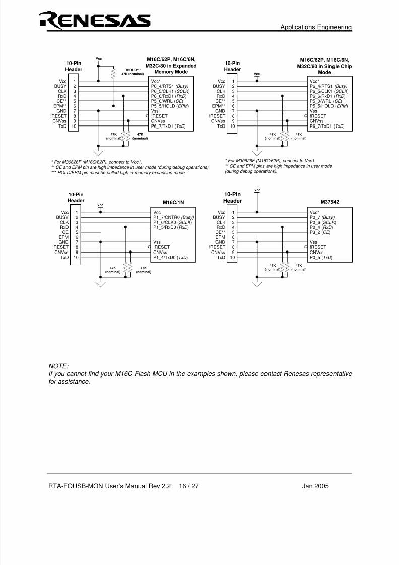
NOTE: If you cannot find your M16C Flash MCU in the examples shown, please contact Renesas representative for assistance.
EPM**
123456789
10
Vcc*P6_4/RTS1 (Busy)P6_5/CLK1 (SCLK )P6_6/RxD1 (RxD )P5_0/WRL (CE )
Vss!RESETCNVssP6_7/TxD1 (TxD )
BUSYVcc
CLKRxDCE**
GND!RESETCNVss
TxD
10-PinHeader
Vcc
47K(nominal)
47K(nominal)
P5_5/HOLD (EPM )
* For M30626F (M16C/62P), connect to Vcc1.** CE and EPM pin are high impedance in user mode (during debug operations).*** HOLD/EPM pin must be pulled high in memory expansion mode.
M16C/62P, M16C/6N,
M32C/80 in ExpandedMemory ModeRHOLD***
47K (nominal)
EPM**
123456789
10
Vcc*P6_4/RTS1 (Busy)P6_5/CLK1 (SCLK )P6_6/RxD1 (RxD )P5_0/WRL (CE )
Vss!RESETCNVssP6_7/TxD1 (TxD )
BUSYVcc
CLKRxDCE**
GND!RESETCNVss
TxD
10-PinHeader
Vcc
47K(nominal)
47K(nominal)
P5_5/HOLD (EPM )
* For M30626F (M16C/62P), connect to Vcc1.** CE and EPM pins are high impedance in user mode (during debug operations).
!RESET
123456789
10
Vcc*P0_7 (Busy)P0_6 (SCLK )P0_4 (RxD )P3_2 (CE )
Vss!RESETCNVssP0_5 (TxD )
10-PinHeader
Vcc
47K(nominal)
47K(nominal)
M37542
EPM
BUSYVcc
CLKRxDCE**
GND
CNVssTxD
M16C/62P, M16C/6N,M32C/80 in Single Chip
Mode
123456789
10
VccP1_7/CNTR0 (Busy)P1_6/CLK0 (SCLK )P1_5/RxD0 (RxD )
Vss!RESETCNVssP1_4/TxD0 (TxD )
BUSYVcc
CLKRxDCE
GND!RESETCNVss
TxD
M16C/1N
10-PinHeader
Vcc
47K(nominal)
47K(nominal)
EPM
8/3/2019 Rta Fousb Mon Users Manual
http://slidepdf.com/reader/full/rta-fousb-mon-users-manual 18/28
Applications Engineering
RTA-FOUSB-MON User’s Manual Rev 2.2 17 / 27 Jan 2005
8. Target MCU Resources Used by ICD for Debugging
This section describes the MCU resources used by the ICD for in-circuit debugging (with the KD30Debugger). These resources are NOT used when the ICD is used for programming (with the FoUSBProgrammer). See previous sections for details on how to connect the hardware for in-circuit debuggingor in-system programming support.
When used as a debug interface, the ICD downloads a small program, called a kernel program (or ROMMonitor), to the target MCU to establish communications used for program debugging operations. Thiskernel program is downloaded to the target MCU when the KD30 application is started.
It is important to note that the operation of the ICD is transparent to the user. There is no specialsoftware processing required to be able to use it as long as the user understands the exceptions andfollows the rules described below.
NOTE: These resources are ONLY used when the ICD is used for in-circuit debugging. Only the MCU pin resources are used when the ICD is used for in-system programming.
a. ROMThe kernel program code is located in the M16C memory space starts at address 0FF900H to 0FFE80H.KD30 will display a message on any attempt to overwrite specified ROM location. Rules on ROM usageare described below.
• User memory allocated to the Kernel program should not be used. Any attempt to use this areaby the user code will be ignored.
• The special page vector table is mapped from 0FFE00H to 0FFFDBH. It is suggested that, ifspecial page jumps are used, the special page numbers start with the minimum value of 20 andincreases to a maximum of 127 to accommodate future monitor size increases.
b. RAMThe kernel program utilizes 128 bytes of RAM memory located at the top of MCU RAM area. For
example, on an M30624 MCU, there is 20Kbytes of RAM located from 00400H to 053FFH. In this case,the monitor will be using the addresses from 05380H to 053FFH. In addition, the monitor also uses 4bytes (max) of RAM on the interrupt stack.In the R8C, there is special debug RAM that is utilized, so no user RAM is required.
c. Interrupts
Many M16C family MCU’s support a special debug interrupt called DBC. For all MCU’s that do NOTsupport DBC interrupt, the kernel program requires that the receive interrupt vector for the monitor/bootUART MUST point to the communications entry point of the monitor, which is 0FF900H. In addition, themonitor reserves the following hardware interrupt vectors for its own use:
• BREAK vector (0FFFE4H)
• ADDRESS MATCH vector (0FFFE8H)
•SINGLE STEP vector (0FFFECH)
• DBC vector (0FFFF4H)
The user code download process will properly load values into these locations. User code that globallydisables interrupts for long periods of time (>1s), may interfere with the proper operation of the monitor.
NOTE: For MCU’s that do NOT have DBC interrupts, always ensure that the global interrupt is enabled in the startup files. Communications between ICD and the kernel program will fail when the global

8/3/2019 Rta Fousb Mon Users Manual
http://slidepdf.com/reader/full/rta-fousb-mon-users-manual 19/28
Applications Engineering
RTA-FOUSB-MON User’s Manual Rev 2.2 18 / 27 Jan 2005
interrupt is not set or disabled for long periods (>1s). This is the primary cause of communication errors while using the KD30 Debugger.
The following list includes MCUs with DBC support:- M16C/26, M16C/28, M16C/29- M16C/62P, M16C/6N4, M16C/6N5- M32C/83, M32C/85
d. PeripheralsThe kernel program uses the serial port associated with the boot mode of the MCU for communicationwith the ICD. Connect the SCLK, TxD, RxD signals from the 10-pin header to this serial port. Forexample, in the case of M30624 MCU, the monitor uses UART1 as the boot UART.
For MCU’s that do NOT support DBC, ensure that the interrupt vector for the boot UART is set to FF900h.
Avoid byte-writes to the (boot UART/SIO) port, including direction register, associated with the SIO whenthe other half of the port is used as General Purpose I/O (GPIO) pins. Byte-writes to the port and directionregister may prevent the monitor program from functioning properly. Use read-modify-write instructionsinstead.
If possible, avoid using this serial port for other applications in the firmware when the ICD will be used fordevelopment.
e. Real-Time CapabilityPlease be aware that while the kernel program is in its “STOP”ed state, the hardware peripherals willcontinue to run. Therefore, interrupts may not be serviced properly. Also, the watchdog timer will not beserviced and will likely timeout if active.
NOTE: While the kernel program is in its “RUN”ning state, there is no overhead on the application code, UNLESS a RAM monitor window is open in KD30. This window requires periodic communication with the target MCU, which suspends normal application operation while servicing the request (approximately 2000 BCLK cycles for each 16 bytes of data displayed in the window are used per window update). The user
must determine whether or not, this behavior is acceptable .
f. Software Summary and Precautions
• Ensure that global interrupt is set in the startup file and not disabled for long periods (>1s).
• Do NOT use the RAM or ROM memory as specified in sections 8.a and 8.b.
• Avoid byte-writes to the port and direction register to avoid interfering with monitor operationassociated with the boot SIO/UART. Use bit manipulations.
• Do NOT change boot UART configuration.
• Ensure that the boot SIO/UART vector is properly set-up to point to FF900H for those M16CMCU’s that do NOT support/have DBC interrupt.
• Do NOT attempt to debug watchdog, WAIT mode, or STOP mode.
• Do NOT execute a ‘STEP’ operation after a write to PRC2 SFR.

8/3/2019 Rta Fousb Mon Users Manual
http://slidepdf.com/reader/full/rta-fousb-mon-users-manual 20/28
Applications Engineering
RTA-FOUSB-MON User’s Manual Rev 2.2 19 / 27 Jan 2005
Appendix A. ICD Board Specifications
The following table lists the specifications for the ICD Board.
Table A.1 ICD SpecificationItem Description
USB MCU Renesas M37641F8HP (8-bit USB Flash MCU)Interface PC host and target connectivity.
a. USB (J1) Full speed USB connection and USB 2.0 compliant. Primaryconnection to debug PC.
b. UART Interface (J2) 4-pin header for RS-232C PC connection (TTL Level -RS-232Ctransceiver/circuit is mounted externally).
c. Target Interface (J3) 10-pin connection with starter kit board or target board. Pleaseread ‘Target Board Connectivity’ on how to design the targethardware to connect the ICD.
LED 4 LED’s: 2 red, 1 green, 1 yellow
a. Red (D1) Power LED.
b. Red (D2) Lights up when target MCU is stopped.
c. Green (D3) Lights up when target MCU is running.
d. Yellow (D4) ICD ready status – blinking
Switch, Jumpers Provide additional debug pins, microprocessor mode and powersupply selection.
a. Bus Power (S1) Power selection: Bus powered or target powered.
b. MCU Mode (JP1) CNVss pin for boot mode (shunted) or user mode (open).
c. Debug (JP3) Provide debug pins for external interrupts (INT0, INT1), monitorstatus, counters 0 & 1 output pins.
Power Configuration The ICD will operate either at 5V or 3.3V and may be buspowered (from USB) or target powered. 5V/3.3V selection usingpin 6 of J3 connection to target.
Current Requirements The maximum current draw by the ICD is 50mA.
Board Size 2.75” x 1.15” (70mm x 29 mm)

8/3/2019 Rta Fousb Mon Users Manual
http://slidepdf.com/reader/full/rta-fousb-mon-users-manual 21/28
Applications Engineering
RTA-FOUSB-MON User’s Manual Rev 2.2 20 / 27 Jan 2005
Appendix B. Technical Notes & Limitations
A. MSV1632-SKP Board
When using the ICD with the MSV1632-SKP board, connect a 10KOhm pull-down resistor on
JP9’s (UART1) RXD line to be able to run user code. The monitor program polls the RXD line forthe presence of the ICD before running the user program. Without the pull-down resistor, theM16C/62 MCU will only run the monitor program.

8/3/2019 Rta Fousb Mon Users Manual
http://slidepdf.com/reader/full/rta-fousb-mon-users-manual 22/28
Applications Engineering
RTA-FOUSB-MON User’s Manual Rev 2.2 21 / 27 Jan 2005
Appendix C. Troubleshooting
This section discusses possible problems you may encounter while installing the software (and drivers)and while running the KD30 or FoUSB Programmer applications. This section also discusses thecountermeasures and solutions to resolve these problems.
If, for any reason, you cannot resolve the problem, please contact your Renesas representative forassistance.
C.1 Manual Installation
Before connecting the ICD to your PC, the driver files (inf and sys) files and executables mustbe copied to the C:\MTOOL\FOUSB directory.
To do this, run FoUSB_Vx.xx.exe under \Tools\FoUSB directory on the SKP CD. After theFoUSB Programmer install, if the default directory was used during install, aC:\MTOOL\FoUSB subfolder should have been created. The Windows USB drivers can befound under te USB Drivers folder, i.e. fousb.inf, fousb.sys (driver files to run FoUSB.exe),usbmon.inf, and usbmon.sys (driver files to run KD30).
The C:\MTOOL \ RTA-FOUSB-MON folder contains all latest documentation about the ICDfrom Quick Start Guide to schematics. The development tools can be found under tools folderfrom the CD root. The \tools\kd30 folder contains the KD30 installer executable.
NOTE: If you are using Windows 2000 or XP, you will need Administrator privileges to be able to install the drivers.
(1) Windows 2000(a). Install FoUSB Programmer by double-clicking on fousb.exe from the \Tools\FOUSB
folder of the CD.(b). Copy the fousb.inf and usbmon.inf files from C:\MTOOL\FOUSB\USB Drivers
folder to \WINNT\INF folder.(c). Copy the fousb.sys and usbmon.sys files from C:\MTOOL\FOUSB\USB Drivers
folder to \WINNT\SYSTEM32\drivers folder.(d). Install KD30 by double-clicking on KD30V3R1_e.exe in \tools\kd30 folder, which
can be found on the CD root. It will create \Mtool\KD30 directory on your PC.(e). Copy communi.dll and kd30dll.def from \Tools\ICD\KD30V3R1 folder of the CD to
the C:\Mtool\KD30 directory.(f). Right-click on kd30.exe file on C:\Mtool\KD30 directory and select ‘Send to
Desktop (create a desktop shortcut).
(2) Windows 98(a). Install FoUSB programmer by double-clicking on fousb.exe from the \Tools\FOUSB
folder of the CD.(b). Copy the fousb.inf and usbmon.inf files from C:\MTOOL\FOUSB\USB Drivers
folder to \WINDOWS\INF folder.
(c). Copy the fousb.sys and usbmon.sys files from C:\MTOOL\\FOUSB\USB Drivers folder to \WINDOWS\SYSTEM32\drivers folder.
(d). Install KD30 by double-clicking on KD30V3R1_e.exe in \tools\kd30 folder, whichcan be found on the CD root. It will create C:\Mtool\KD30 directory on your PC.
(e). Copy communi.dll and kd30dll.def from \Tools\ ICD\KD30V3R1 folder of the CD tothe C:\Mtool\KD30 directory.
(f). Right-click on kd30.exe file on \Mtool\KD30 directory and select ‘Send to Desktop(create a desktop shortcut).

8/3/2019 Rta Fousb Mon Users Manual
http://slidepdf.com/reader/full/rta-fousb-mon-users-manual 23/28
Applications Engineering
RTA-FOUSB-MON User’s Manual Rev 2.2 22 / 27 Jan 2005
C.2 Driver Problems
This part discusses the usual problems with the driver installation and how to fix it. The mostcommon problem encountered is, Windows did not properly install the driver and so the ICDis not recognized. This may also cause the device status to indicate that the device is notworking properly. An indication of this problem is the ICD’s Status LED (yellow), it should beblinking at about 2-3 times a second. When the driver is installed properly, the Status LEDonly blinks every second.
Before trying the following steps, try re-starting your PC to see if this resolves the problem.You can check the status using the Device Manager. If the ICD appears under the UniversalSerial Bus Controllers with NO red X or yellow exclamation point, the driver was installedproperly.
For cases where the ‘Device Status’ states the device is not working properly, please try thefollowing:
1. Double-click on ‘Renesas USB ICD’ and a Renesas USB ICD Properties dialog boxappears.
2. Click on ‘Driver’ tab and click on ‘Update Driver’ button.
3. Select ‘Display a list…’ and click on ‘Have Disk’ button.4. Locate the C:\MTOOL\FOUSB\USB Drivers folder and install ‘usbmon.sys’ driver.5. If this process does not work, please follow instructions below.
For cases where in the driver was not installed properly by Windows (Windows 98, Windows2000) or not listed in the Device Manager > Universal Serial Bus Controllers, please try thefollowing:
1. Unplug the USB Cable so Windows removes driver from memory.2. Delete the driver ‘usbmon.sys’ from ‘\WINNT\SYSTEM32\DRIVERS\ folder in Windows
2000 or \WINDOWS\SYSTEM32\DRIVERS folder in Windows 98.3. Plug in ICD + target and try installing the driver as written above and use the driver from
the C:\MTOOL\FOUSB\USB Drivers.

8/3/2019 Rta Fousb Mon Users Manual
http://slidepdf.com/reader/full/rta-fousb-mon-users-manual 24/28
Applications Engineering
RTA-FOUSB-MON User’s Manual Rev 2.2 23 / 27 Jan 2005
C.3 KD30 Problems
The common problems encountered with KD30 are: USB cannot be selected on theinitialization screen, cannot connect to target, and KD30 already exist. This part discussesthe cause of the problem and the countermeasures to resolve it.
When USB cannot be selected, you have an old version of KD30. Un-install the currentversion and delete the KD30 folder under C:\MTOOL. Run the latest KD30 install from theSKP CD or download the file from the Renesas Tools website.
When the message ‘Can’t connect with the target’ is displayed, there are several reasons thatmay cause this message to appear. We’ll discuss each cause and the correspondingcountermeasure.
(1) The ICD is not connected to the PC. Please connect the ICD to your PC.
NOTE: Regardless of whether the ICD is bus or target powered, please connect target board to ICD first before plugging the USB cable to your PC.
(2) The ICD to target cable is not connected. Please connect the ICD to the target boardusing the 10-pin flat ribbon cable.
(3) There is insufficient bus power to run the ICD and target board. Bus power cansupply up to 100mA to both ICD and SKP boards. Renesas SKP boards weredesigned so that the combination of ICD and SKP board will be under 100mA limit. Ifyour target board is a non-Renesas SKP board, change the S1 Power Mode switchto TARGET and connect an external power supply to your target board.
(4) The target MCU programmed on the ICD during KD30 initialization does not matchthe actual target MCU. Close the error message by clicking on ‘OK’ button and thenclick on ‘Cancel’ button of the KD30 Init window to close KD30. Select the correctMCU from the Refer button of the KD30 Init screen.
(5) The hardware connection on the target board does not follow the specification forconnection between the ICD and target board. Please review the connection and
check your circuit. Refer to section 7 in this manual, ‘Target Hardware Connectivityfor In-Circuit Debugging’.
(6) The target MCU maybe damaged. Try a different target board and MCU.
When a message ‘KD30 already exists’ is displayed, the usual reason for this problem is thatthe KD30 application was not properly closed. Please check if KD30 is already running bylooking at your task bar. If KD30 cannot be found there, bring up Task Manager (for Windows2000, right-click on Task Bar and select ‘Task Manager’; for Windows 98, ME or XP, pressCTRL-ALT-DEL and select ‘Task Manager’). Select KD30.exe on the ‘Processes’ list andclick on ‘End Process’ to terminate KD30.

8/3/2019 Rta Fousb Mon Users Manual
http://slidepdf.com/reader/full/rta-fousb-mon-users-manual 25/28
Applications Engineering
RTA-FOUSB-MON User’s Manual Rev 2.2 24 / 27 Jan 2005
C.4 FoUSB Programmer Problems
This section describes common problems, causes, and countermeasures when working withthe FoUSB Programmer. The common problems with FoUSB Programmer are: FoUSBProgrammer does not come up, device is not detected, or target is not connected.
When FoUSB Programmer does not come up properly, the main reason is that the MCU textfile list folder does not exist on the folder where the FoUSB Programmer executable is. TheMCU text file is a list of all MCU’s that the FoUSB Programmer supports. Please read‘Installing Required Files Manually’ on running fousb.exe to fix the problem.
If you encounter a ‘device is not detected’, the possible causes and countermeasures arelisted below.
(1) The ICD and target board is not connected to the PC. Please plug one end of theUSB cable to the ICD and the other end to the PC. Make sure you connect the ICD tothe target board first before plugging the USB cable to the PC.
(2) The FoUSB Programmer driver (fousb.inf and fousb.sys) was not installed properly.Please refer to section C.1, ‘Installing Required Files Manually’.
(3) The ICD has no user ROM firmware. Please refer to section C.5, ‘Using the ICD’s
Boot Mode’ to program the user ROM firmware.
If you encounter a ‘target is not connected’, the possible causes and countermeasures arelisted below.
(1) The target board is not connected to the ICD. Please unplug the USB cable first andthen connect the target board to the ICD with the 10-pin flat ribbon cable beforeplugging back the USB cable to your PC.
(2) The target MCU is not a flash version. The ICD can only communicate with M16Cflash MCU’s through it’s boot program. Please verify if the target MCU is a flash part.
(3) The hardware connection on the target board does not follow the specification forconnection between the ICD and target board. Please review the connection andcheck your circuit. Refer to section 6 in this manual, ‘Target Hardware Connectivity
for In-System Programming’.(4) The target MCU maybe damaged. Try a different target board and MCU.
8/3/2019 Rta Fousb Mon Users Manual
http://slidepdf.com/reader/full/rta-fousb-mon-users-manual 26/28
Applications Engineering
RTA-FOUSB-MON User’s Manual Rev 2.2 25 / 27 Jan 2005
C.5 Re-programming the ICD
This section discusses how to re-program the ICD if for some reason the user ROM firmwarewas erased or damaged. A good indication that the ICD needs to be re-programmed is whenthere is no yellow LED flashing, yet the red power LED is on.
The ICD has a boot mode that can be used to program the user ROM area. When the ICDwas shipped, the user ROM firmware was pre-programmed with firmware that cancommunicate with the FoUSB Programmer and KD30 Debugger. However, in the event thatthis firmware got erased or damaged, you can use this boot mode to re-program the ROMfirmware.
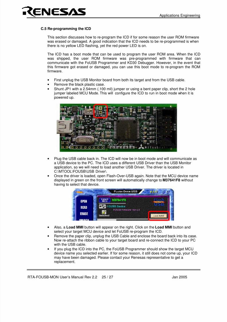
• First unplug the USB Monitor board from both its target and from the USB cable.
• Remove the black plastic case.
• Shunt JP1 with a 2.54mm (.100 mil) jumper or using a bent paper clip, short the 2 hole jumper labeled MCU Mode. This will configure the ICD to run in boot mode when it ispowered up.
• Plug the USB cable back in. The ICD will now be in boot mode and will communicate asa USB device to the PC. The ICD uses a different USB Driver than the USB Monitorapplication, so we will need to load another USB Driver. The driver is located inC:\MTOOL\FOUSB\USB Driver\.
• Once the driver is loaded, open Flash-Over-USB again. Note that the MCU device namedisplayed in green on the front screen will automatically change to M37641F8 withouthaving to select that device.
• Also, a Load MMI button will appear on the right. Click on the Load MMI button andselect your target MCU device and let FoUSB re-program the ICD.
• Remove the paper clip, unplug the USB Cable and enclose the board back into its case.Now re-attach the ribbon cable to your target board and re-connect the ICD to your PCwith the USB cable.
• If you plug the ICD into the PC, the FoUSB Programmer should show the target MCUdevice name you selected earlier. If for some reason, it still does not come up, your ICDmay have been damaged. Please contact your Renesas representative to get areplacement.

8/3/2019 Rta Fousb Mon Users Manual
http://slidepdf.com/reader/full/rta-fousb-mon-users-manual 27/28
Applications Engineering
RTA-FOUSB-MON User’s Manual Rev 2.2 26 / 27 Jan 2005
Appendix D. Reference Manuals
Item Title Description1. RTA-FOUSB-MON Quick Start Guide Document that will help you get started on using the
ICD. 2. RTA-FOUSB-MON User's Manual This document.
3. ICD Board Schematic Schematic diagram for the ICD board. 4. ICD Board BOM Bill of materials for the ICD board. 5. M16C/20/60 Series C-Language
Programming Manual ANSI C-language programming guide for theM16C/20/60 series MCU.
6. M16C/20/60 Series AssemblerLanguage Programming Manual
Assembly language programming guide for theM16C/20/60 series MCUs.
7. HEW User's Manual This document describes installation and operationof this Integrated Development Environment forRenesas' Tools.
8. KD30 User's Manual The HELP file that runs with KD30 provides all usermanual information.
9. AS30 User's Manual Guide for AS30 assembler. 10. NC30 User's Manual Guide for NC30WA compiler.
11. Target Setup for In-Circuit Debugger Application note for ICD12. Target Setup for FoUSB Programmer Application note for FoUSB
13. Firmware Requirements for In-CircuitDebugger Support
Application note for ICD
NOTE: The RTA-FOUSB-MON installer will copy all these manuals during installation. They can be accessed using the Document Descriptions file by clicking on the Start > Programs > Renesas-Tools > RTA- FOUSB-MON > Document Descriptions.
8/3/2019 Rta Fousb Mon Users Manual
http://slidepdf.com/reader/full/rta-fousb-mon-users-manual 28/28
Applications Engineering
Appendix E. Board Schematic & BOM
The circuit board schematic and BOM are available as separate documents,
RTA-FoUSB-MON_Schematic_RevX.pdf andRTA-FoUSB-MON_Board_BOM_RevX.pdf respectively.


