134
RTD BUS TRANSIT FACILITY DESIGN GUIDELINES AND CRITERIA Regional Transportation District February, 2006
RTD Bus TRansiT FaciliTy Design guiDelines
anD cRiTeRia
Regional Transportation District February, 2006
RTD BUS TRANSIT FACILITY
DESIGN GUIDELINES AND CRITERIA
Regional Transportation District February 2006
Prepared by the Engineering Division of the Regional Transportation District
Regional Transportation District 1600 Blake Street
Denver Colorado 80202 1399
303 628 9000
RTD Denver Com
miD
February 27 2006
The RTD Bus Transit Facility Design Guidelines and Criteria has been developed as a set of
general guidelines as well as providing specific criteria to be employed in the preparation and
implementation of the planning design and construction of new bus transit facilities and
improvements to existing facilities This 2006 issue of the RTD Bus Transit Facility DesignGuidelines and Criteria was developed to remain in compliance with accepted practices with
regard to safety and compatibility with RTD s existing system and the intended future systemsthat will be constructed by RTD The manual reflects the most current accepted practices and
applicable codes in use by the industry
The intent of this manual is to establish general criteria to be used in the planning and designprocess However deviations from these accepted criteria may be required in specificinstances Any such deviations from these accepted criteria must be approved by the RTD s
Executive Safety Security Committee
Coordination with local agencies and jurisdictions is still required for determining requirementupdates fire protection life safety zoning platting land development and security measures
approvals that will be implemented as part of the planning and design of RTD facilities
Conflicting information or directives between the criteria set forth in this manual shall be
brought to the attention of RTD and will be addressed and resolved between RTD and the local
agencies or jurisdictions
This manual will be updated periodically either in part or in whole as deemed appropriate byRTD Any updates or modifications to the manual will take precedence over previous versions
or criteria at the time of approval of the updated material or sections of the manual
Submitted by
evCfJo n C Shonsey P E
Senior Manager of Engineering
S AStan A Szabela P E
Civil Engineering ManagRonald W Dodsworth
ssis ant General Manager Bus Operations
v
Michael J Gil
General SuperintendDa id A Genova
of Street Operations Manager of Public Safety
1 JMptsWilliam C Porter
Manager Service Development
TABLE OF CONTENTS
TITLE SECTION
Introduction ................................................................................... 1
Bus Transit Facility Design ............................................................... 2
Civil Design.................................................................................... 3
Urban and Landscape Design Elements.............................................. 4
Bicycle Facilities ............................................................................. 5
Structural Design............................................................................ 6
Drivers Relief Station....................................................................... 7
Signage ......................................................................................... 8
Lighting and Electrical ..................................................................... 9
Communications, Fare Collection and Power .....................................10
Construction Documents ................................................................11
System Safety and System Security ................................................12
RTD Design Guidelines & Criteria Table of Contents Bus Transit Facility Design Guidelines and Criteria February 2006
Page 1 of 1
SECTION 1 - INTRODUCTION 1.1.0 BUS TRANSIT FACILITIES .............................................................................. 2
1.2.0 SCOPE ......................................................................................................... 3
1.3.0 PROCEDURES ............................................................................................... 4
1.4.0 DESIGN CODES AND MANUALS ..................................................................... 4
1.5.0 CLIMATIC CONDITIONS FOR SYSTEMS DESIGN............................................... 6
1.6.0 ACRONYMS AND ABBREVIATIONS................................................................. 8
1.7.0 TRANSIT FACILITY TYPES ............................................................................. 9
1.8.0 COMMUNITY INTEGRATION AND TRANSIT ORIENTED DEVELOPMENT (TOD) ... 10
1.9.0 PEDESTRIAN AND PASSENGER FACILITY REQUIREMENTS.............................. 11
1.10.0 DISABILITY RIGHTS LAWS .......................................................................... 11
1.10.1 ADA Accessible Parking................................................................. 11
1.11.0 BUS BOARDING AND ALIGHTING AREAS...................................................... 12
1.12.0 PROVIDING FOR THE TRANSIT VEHICLE ....................................................... 13 1.13.0 DESIGNING FOR THE TRANSIT VEHICLE ....................................................... 13
1.13.1 Bus Access and Parking Requirements............................................. 13 1.13.2 Other Operational Design Considerations ......................................... 14
1.14.0 PROVIDING FOR PRIVATE VEHICLES (AUTO, BIKE & MOTORCYCLE) ............... 15
RTD Design Guidelines & Criteria Section 1 – Introduction Bus Transit Facility Design Guidelines and Criteria February 2006
Page 1 of 15
SECTION 1 - INTRODUCTION
1.1.0 BUS TRANSIT FACILITIES
RTD bus transit facilities are intermodal transfer facilities. They provide collection and distribution points for travelers who transfer between auto and transit (bus or rail) modes, single occupant vehicles and high occupancy vehicle (vanpools or carpools) modes, transit modes (bus to bus, bus to rail and rail to bus) or by other means. Bus transit facilities require proper planning and forethought to serve this array of modal transfers, which if accomplished will optimize the facility activity and better integrate it with the surrounding community. Other modes supported by a properly designed bus transit facility may include: pedestrian, bicycle, paratransit, inner- and inter-city bus transit, airport service and rail (LRT and commuter).
Differing transit facility design views are held within engineering and planning professions. At one extreme, the primary goal is to maximize its efficiency as an extension of the highway or transit network. At the other extreme, the primary goal maximizes community integration characteristics and reduces regional transportation connectivity needs. RTD integrates both extremes and provides a coordinated design that equally serves the highway transit network and community integration. The level of coordinated design shall be appropriate to the surrounding existing and planned roads and land uses.
Experience and surveys show that facilities achieve success (measured by demand and operating expense) if form follows function. Design professionals shall consider the various access, circulation and service modes of the transit facility and shall include pedestrian and bicycle movements. These concerns and design requirements are at the top of the design priority list. Close attention to these issues will produce a superior facility with reduced maintenance requirements, lower operating costs and manageable security risks.
Many components are required for the design and development of a successful multimodal and intermodal transit facility. These components fall into the following eight categories:
• Functional zones (access, transfer, circulation, plazas, boarding, seating, lighting, utilities, drainage, information and fare collection) of a transit facility
• Designing a community integrated facility
• Providing for the design needs of pedestrians and bicyclists
• Compliance with ADA requirements and guidelines
• Providing for the design requirements of transit vehicles, automobiles and maintenance equipment
• Design considerations for facility access management
• Design considerations for convenient, efficient and cost effective maintenance
• Design considerations for safety and security management
Although a hierarchy can be applied to the eight categories, each is important to the success of the proposed facility. All bus transit facility designs shall address and integrate each of the above categories.
RTD Design Guidelines & Criteria Section 1 – Introduction Bus Transit Facility Design Guidelines and Criteria February 2006
Page 2 of 15
Access, circulation, storage and parking for transit, automobile, bicycle and pedestrian modes, and their requirements, services, amenities and conveniences shall provide smooth and seamless transfer capabilities, and promote efficient facility management.
The pedestrian mode is a component for all commuter trips. Design considerations, within a facility and surrounding land uses, shall provide for and promote pedestrian flow.
Bicycle access, circulation and parking and storage design shall be included with the facility and integrated with adjacent bike routes and pedestrian paths. Bicycles and automobiles must be accommodated for on-site circulation and parking.
As required, automobile parking lot (park-and-ride; pnR) sizes will vary pursuant to estimated demands. The pnR design shall be based on site characteristics such as parcel shape, topography and available access. They are classified as small, medium and large:
• A small pnR may be located on a remnant few acres parcel along a freeway, adjacent to a freeway access ramp, or other site with no special access features, with a 200 space or less capacity, and a bus loading area along a parallel street.
• A medium pnR may be located on an 8 acre parcel with a parking capacity of more than 200 and less than 1,000 spaces, and a bus loading area within the facility and a dedicated transit vehicle access driveway loop.
• A large pnR lot may be located on a 15 acre site with a parking capacity of 1,000 or more spaces, with multiple transit vehicle loading areas and possibly different transit modes (e.g., I-25 & Broadway, Mineral or Wagon Road at I-25).
The following is an approximate parking space count to lot size ratio used by RTD for planning purposes:
• 70 spaces per acre for a large pnR with several bus loops, multiple plaza areas, many pedestrian circulation routes and extensive amenities
• 75 spaces per acre for a medium pnR with a single bus loop, several plaza areas, pedestrian circulation routes and other amenities
• 80 spaces per acre for a small pnR with no internal bus loop (street stop only), single plaza area, limited pedestrian circulation routes and few amenities
1.2.0 SCOPE
The Design Criteria take precedence over other standards referred to herein except those required by legislation.
Specific attention shall be given to the most recent version of the Americans with Disabilities Act (ADA).
These Design Criteria relate to the following RTD design and construction elements:
• Bus Transit Facility Design
• Civil Design
• Urban and Landscape Design
RTD Design Guidelines & Criteria Section 1 – Introduction Bus Transit Facility Design Guidelines and Criteria February 2006
Page 3 of 15
• Bicycle Facilities
• Structural Design
• Driver Relief Station
• Signage
• Lighting and Electrical
• Communication, Fare Collection and Power
• Construction Documents
• Facility and System Safety and Security
1.3.0 PROCEDURES
Design Engineers shall prepare drawings and technical specifications for each project in accordance with their design contract, as applicable, and the following RTD documents:
• All RTD Design Criteria Manuals
• RTD CADD Standards
• Contract Requirements
• All other applicable requirements including codes, regulatory standards and environmental impact statements
Deviations may be made within the framework of the Design Criteria to meet specific case-by-case requirements. Any deviation, discrepancy or unusual solution must be discussed with and approved by RTD before it is advanced and included in the design. The Design Engineer shall identify, explain and justify all deviations from the criteria and secure written approval from RTD. Any variation from these Design Criteria must be submitted to and approved by RTD’s Executive Safety and Security Committee. All proposed deviations to these criteria shall be approved by RTD in writing.
Where manufactured products are specified, alternative products are acceptable if the proposed substitution is an approved equivalent and approved by RTD in writing.
1.4.0 DESIGN CODES AND MANUALS
The Design Engineer shall comply with all applicable engineering codes, standards, and all Federal, State and local jurisdictional requirements.
The most recent edition(s) of codes, manuals and requirements specified herein shall be used. Responsibility for all designs remains with the Design Engineer in accordance with the terms and conditions of the design contract.
The Design Engineer shall identify all known or apparent code conflicts, shall notify RTD in writing and shall recommend a solution. The Design Engineer shall confirm those codes and manuals that have precedence.
RTD Design Guidelines & Criteria Section 1 – Introduction Bus Transit Facility Design Guidelines and Criteria February 2006
Page 4 of 15
Specific codes, standards and design guidelines include, but are not limited to, the following:
• Americans with Disabilities Act (ADA)
• Americans with Disabilities Act Accessibility Guidelines for Buildings and Facilities (ADAAG)
• Americans with Disabilities Act Accessibility Guidelines for Transportation Vehicles
• Colorado Department of Transportation (CDOT) - Standard Specifications for Road and Bridge Construction
• CDOT - Standard Plans (M&S Standards)
• CDOT - Design Guide
• CDOT – Drainage Design Manual
• CDOT – Bridge Design Manual
• City and County of Denver - Rules for Street Standards
• City and County of Denver - Standard Construction Specifications
• FHWA - Manual on Uniform Traffic Control Devices for Streets and Highways (MUTCD)
• Metropolitan Government Pavement Engineers Council (MGPEC) - Pavement Design Standards and Construction Specifications
• RTD – Facilities Standard and Directive Drawings for Bus and Light Rail Transit Facility Projects (RTD Standard Drawings)
• Uniform Building Code (UBC)
• International Building Code (IBC)
• Uniform Fire Code (UFC)
• American Association of State Highway and Transportation Officials (AASHTO)
• American Institute of Steel Construction (AISC)
• American Welding Society (AWS)
• American Concrete Institute (ACI)
• American Society for the Testing of Materials (ASTM)
• National Bureau of Standards
• National Electric Code (NEC)
• National Electric Safety Code (NESC)
• American National Standards Institute (ANSI)
• National Fire Protection Association (NFPA) including NFPA 130 and 101
• Local jurisdictional codes, requirements and ordinances, as applicable
Individual sections of these criteria may also define additional code requirements.
RTD Design Guidelines & Criteria Section 1 – Introduction Bus Transit Facility Design Guidelines and Criteria February 2006
Page 5 of 15
1.5.0 CLIMATIC CONDITIONS FOR SYSTEMS DESIGN
The Denver metropolitan area, within which RTD operates, is situated east of the Rocky Mountains, near and within the eastern slopes of the Rocky Mountain foothills in central Colorado. The area has a semi-arid climate similar to the High Plains, but is modified by the Rocky Mountains located west of the area. Denver lies in a belt where there is a fairly rapid change in climate from the foothills to the plains. This change is largely caused by the increase in elevation towards the westerly foothills. Denver has an elevation of 5,280 feet.
The average annual temperature is about 50°F and it varies a few degrees with changes in elevation. The wide average range in daily temperature of 25° to 30°F in the Denver metropolitan area and a wide average range in annual temperature are typical for the High Plains. Variations in temperature are wide from day to day; extremely hot weather in summer and extremely cold weather in the winter normally do not last long and are followed by much more moderate temperatures.
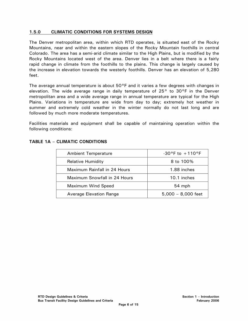
Facilities materials and equipment shall be capable of maintaining operation within the following conditions:
TABLE 1A – CLIMATIC CONDITIONS
Ambient Temperature -30°F to +110°F
Relative Humidity 8 to 100%
Maximum Rainfall in 24 Hours 1.88 inches
Maximum Snowfall in 24 Hours 10.1 inches
Maximum Wind Speed 54 mph
Average Elevation Range 5,000 – 8,000 feet
RTD Design Guidelines & Criteria Section 1 – Introduction Bus Transit Facility Design Guidelines and Criteria February 2006
Page 6 of 15
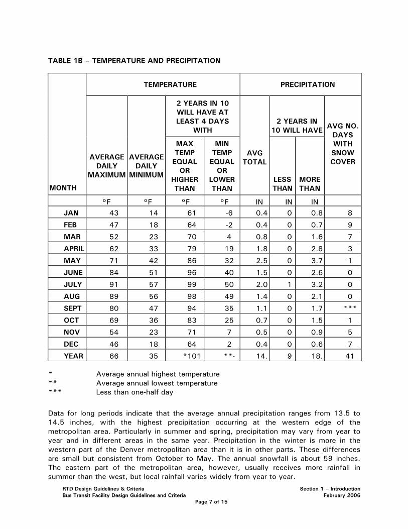
TABLE 1B – TEMPERATURE AND PRECIPITATION
TEMPERATURE PRECIPITATION
2 YEARS IN 10 WILL HAVE AT LEAST 4 DAYS
WITH 2 YEARS IN
10 WILL HAVE
MONTH
AVERAGE DAILY
MAXIMUM
AVERAGE DAILY
MINIMUM
MAX TEMP EQUAL
OR HIGHER THAN
MIN TEMP EQUAL
OR LOWER THAN
AVG TOTAL
LESS THAN
MORE THAN
AVG NO. DAYS WITH SNOW COVER
°F °F °F °F IN IN IN JAN 43 14 61 -6 0.4 0 0.8 8
FEB 47 18 64 -2 0.4 0 0.7 9
MAR 52 23 70 4 0.8 0 1.6 7
APRIL 62 33 79 19 1.8 0 2.8 3
MAY 71 42 86 32 2.5 0 3.7 1
JUNE 84 51 96 40 1.5 0 2.6 0
JULY 91 57 99 50 2.0 1 3.2 0
AUG 89 56 98 49 1.4 0 2.1 0
SEPT 80 47 94 35 1.1 0 1.7 ***
OCT 69 36 83 25 0.7 0 1.5 1
NOV 54 23 71 7 0.5 0 0.9 5
DEC 46 18 64 2 0.4 0 0.6 7
YEAR 66 35 *101 **- 14. 9 18. 41
* Average annual highest temperature ** Average annual lowest temperature *** Less than one-half day
Data for long periods indicate that the average annual precipitation ranges from 13.5 to 14.5 inches, with the highest precipitation occurring at the western edge of the metropolitan area. Particularly in summer and spring, precipitation may vary from year to year and in different areas in the same year. Precipitation in the winter is more in the western part of the Denver metropolitan area than it is in other parts. These differences are small but consistent from October to May. The annual snowfall is about 59 inches. The eastern part of the metropolitan area, however, usually receives more rainfall in summer than the west, but local rainfall varies widely from year to year.
RTD Design Guidelines & Criteria Section 1 – Introduction Bus Transit Facility Design Guidelines and Criteria February 2006
Page 7 of 15
The relative humidity averages 39% during the day and 62% at night, but these averages are slightly higher in winter than in summer. In an average year, the percentage of sunshine is about 69%.
Hailstorms cause some local damage almost every year. The hail usually falls in strips 1 mile wide and 6 miles long. These storms are more common in the eastern part of the Denver metropolitan area than the western part and they generally occur from about May 15 to September 1 but are most common in June and July.
Requirements for climatic conditions defined in other sections of these Design Criteria take precedence.
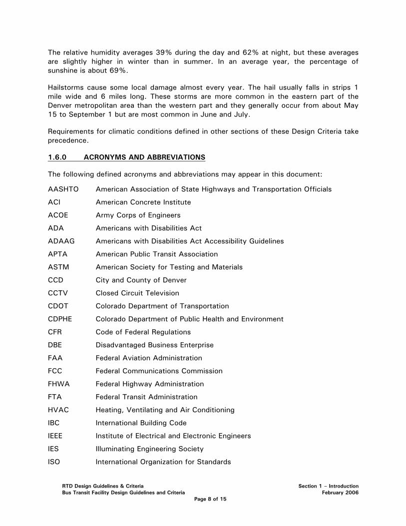
1.6.0 ACRONYMS AND ABBREVIATIONS
The following defined acronyms and abbreviations may appear in this document:
AASHTO American Association of State Highways and Transportation Officials
ACI American Concrete Institute
ACOE Army Corps of Engineers
ADA Americans with Disabilities Act
ADAAG Americans with Disabilities Act Accessibility Guidelines
APTA American Public Transit Association
ASTM American Society for Testing and Materials
CCD City and County of Denver
CCTV Closed Circuit Television
CDOT Colorado Department of Transportation
CDPHE Colorado Department of Public Health and Environment
CFR Code of Federal Regulations
DBE Disadvantaged Business Enterprise
FAA Federal Aviation Administration
FCC Federal Communications Commission
FHWA Federal Highway Administration
FTA Federal Transit Administration
HVAC Heating, Ventilating and Air Conditioning
IBC International Building Code
IEEE Institute of Electrical and Electronic Engineers
IES Illuminating Engineering Society
ISO International Organization for Standards
RTD Design Guidelines & Criteria Section 1 – Introduction Bus Transit Facility Design Guidelines and Criteria February 2006
Page 8 of 15
LED Light Emitting Diode
LOS Level of Service
LRT Light Rail Transit
LRV Light Rail Vehicle
NEC National Electrical Code
NEMA National Electrical Manufacturers Association
NESC National Electrical Safety Code
NETA National Electrical Testing Association
NFPA National Fire Protection Association
OSHA Occupational Safety and Health Administration
PUC Public Utilities Commission
ROW Right of Way
TOD Transit Oriented Development
TVM Ticket Vending Machine
UBC Uniform Building Code
UDFCD Urban Drainage and Flood Control District
UFC Uniform Fire Code
UL Underwriters Laboratories, Inc
USDCM Urban Storm Drainage Criteria Manual
USDOT United States Department of Transportation
1.7.0 TRANSIT FACILITY TYPES
The types of bus transit facilities are as follows:
• Park and Ride (pnR)
• Bus Rapid Transit (BRT) with/without expanded “Super Stop”
• Transfer Station (pulse point) with no, or limited short-term parking (kiss-and-ride)
• Street-side Bus Stop
The functions and services include modal transfers to other buses, rail and personal vehicles (autos, trucks, vans and bicycles). Vehicle, pedestrian and bicycle circulation shall be accommodated within the transit facility. Additionally these movements may occur to and from adjacent areas of Transit Oriented Development (TOD), residence, employment, commerce, industry, learning, sport and entertainment centers. All shall adhere to applicable ADA requirements.
The functional zones of transit facilities associated with specific bus operating activities are further discussed in the following sections.
RTD Design Guidelines & Criteria Section 1 – Introduction Bus Transit Facility Design Guidelines and Criteria February 2006
Page 9 of 15
A facility type and the size of its functional zones shall depend upon specific planning, community and environmental requirements. For example, an informal or opportunistic lot may provide only long-term parking and a transit loading area. In another case, the functional requirements of bus operations may require a specific number of bus loading bays, while identifying the need for independent bus arrivals and departures. In conjunction with RTD, the Design Engineer shall design site layouts that accommodate the number of transit vehicles and also determine the need for other transit facility types.
The Design Criteria shall be carefully applied so that the design fits local conditions, safely connects with roadway networks, meets local government codes and regulations and is easily maintained. RTD supports creativity and flexibility to encourage solutions that are constrained by local conditions and to use standard transit design elements that maximizes maintenance efficiencies. Many of the design parameters relate to the bus-oriented pnR facility. These concepts can also be directly applied to rail oriented pnR facilities.
Call-n-Ride services may be incorporated at any RTD bus transit facility in coordination with RTD service development division.
1.8.0 COMMUNITY INTEGRATION AND TRANSIT ORIENTED DEVELOPMENT (TOD)
Some concerns about bus transit facilities are that they do not discourage private automobile travel, have undesirable community and environmental impacts and are perceived to attract criminal activity. A successfully integrated design will mitigate these concerns, ease other apprehensions associated with bus transit facilities and provide the community with better transit facilities.
The community demands well built public works projects, and is very attentive to projects in areas where vacant land is scarce, environmental concerns are dominant, and local development or in-fill redevelopment activities are vigorous. In these areas, transit is becoming the solution to resolving traffic congestion, air pollution concerns and economic development. A community integrated facility will provide the maximum benefit to be realized from a fully intermodal/multimodal transit facility.
A community integrated facility benefits transit ridership and increases potential revenue streams for RTD and the community tax base. Better access improves community integration and promotes adjacent development. An integrated pnR can provide a focal point for future urban and transit oriented development (TOD).
A coordinated effort is required for a successfully integrated transit facility, and may involve several jurisdictions. Transit oriented zoning, platting and deed restrictions (easements) that promote transit facilities and TOD in the vicinity of the facility are beneficial for a successful community integration. There must also be a market for the facility and accompanying transit services in the community.
RTD Design Guidelines & Criteria Section 1 – Introduction Bus Transit Facility Design Guidelines and Criteria February 2006
Page 10 of 15
1.9.0 PEDESTRIAN AND PASSENGER FACILITY REQUIREMENTS
A transit facility consists of four elements:
1. personal vehicle (car, motorcycle and bicycle) accommodation
2. passenger facility
3. pedestrian access space
4. open space (detention and landscaping)
Efficient operations require that all elements work in harmony, which provides a smooth and seamless intermodal transition from the personal vehicle, via the pedestrian mode to the transit system. Other access and egress modes shall be included within this three-part system.
Pedestrian related factors shall be considered when designing a successful transit facility. At the site-specific level, the design shall include: the general site layout, pedestrian and vehicle circulation routes and the intermodal bus plaza area.
The following shall be considered when designing for pedestrians:
• Separation of competing modes
• Provision of pedestrian pathways
• Provision of adequate pedestrian waiting areas (4 sf/ person min.)
• Compliance with the ADA requirements and guidelines
• Provide safe environments (adequate lighting and shelter)
• Manage conflict points between pedestrian, bus and vehicle movements
1.10.0 DISABILITY RIGHTS LAWS
Specific attention should be given to the Americans with Disabilities Act (ADA), the ADA Accessibility Guidelines for Building and Facilities (ADAAG), the ADA Accessibility Guidelines for Transportation Vehicles and to any succeeding modifications that may be issued. Their applicability is noted in several sections of this Manual where apparent or appropriate significance apply. Adherence to ADA and ADA related guidelines is required for all areas of this Manual, regardless of explicit, implied or lack of reference herein.
1.10.1 ADA Accessible Parking
The number of ADA accessible parking spaces shall be coordinated with local jurisdictions to ensure that their requirements are met. If local codes are more stringent than Federal guidelines, the more stringent shall be followed. At least one van accessible space shall be placed at the site, and additional ones for every eight ADA spaces are required. Table 1C summarizes the number of accessible car parking spaces required per facility by current ADA requirements.
RTD Design Guidelines & Criteria Section 1 – Introduction Bus Transit Facility Design Guidelines and Criteria February 2006
Page 11 of 15
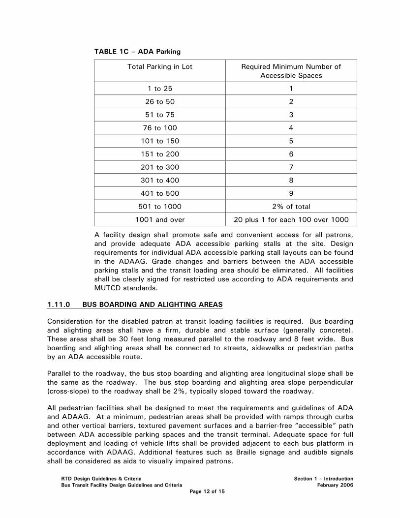
TABLE 1C – ADA Parking
Total Parking in Lot Required Minimum Number of Accessible Spaces
1 to 25 1
26 to 50 2
51 to 75 3
76 to 100 4
101 to 150 5
151 to 200 6
201 to 300 7
301 to 400 8
401 to 500 9
501 to 1000 2% of total
1001 and over 20 plus 1 for each 100 over 1000
A facility design shall promote safe and convenient access for all patrons, and provide adequate ADA accessible parking stalls at the site. Design requirements for individual ADA accessible parking stall layouts can be found in the ADAAG. Grade changes and barriers between the ADA accessible parking stalls and the transit loading area should be eliminated. All facilities shall be clearly signed for restricted use according to ADA requirements and MUTCD standards.
1.11.0 BUS BOARDING AND ALIGHTING AREAS
Consideration for the disabled patron at transit loading facilities is required. Bus boarding and alighting areas shall have a firm, durable and stable surface (generally concrete). These areas shall be 30 feet long measured parallel to the roadway and 8 feet wide. Bus boarding and alighting areas shall be connected to streets, sidewalks or pedestrian paths by an ADA accessible route.
Parallel to the roadway, the bus stop boarding and alighting area longitudinal slope shall be the same as the roadway. The bus stop boarding and alighting area slope perpendicular (cross-slope) to the roadway shall be 2%, typically sloped toward the roadway.
All pedestrian facilities shall be designed to meet the requirements and guidelines of ADA and ADAAG. At a minimum, pedestrian areas shall be provided with ramps through curbs and other vertical barriers, textured pavement surfaces and a barrier-free “accessible” path between ADA accessible parking spaces and the transit terminal. Adequate space for full deployment and loading of vehicle lifts shall be provided adjacent to each bus platform in accordance with ADAAG. Additional features such as Braille signage and audible signals shall be considered as aids to visually impaired patrons.
RTD Design Guidelines & Criteria Section 1 – Introduction Bus Transit Facility Design Guidelines and Criteria February 2006
Page 12 of 15
1.12.0 PROVIDING FOR THE TRANSIT VEHICLE
The required transit facility service will determine the design vehicle parameters. Transit service and access is as important as pedestrian access. Specific transit design elements for individual facilities will depend on the vehicles accessing and serving the site and the operational requirements. The design parameters may include Bus Rapid Transit (BRT) systems. The Design Engineer shall coordinate with RTD and determine the types and number of vehicles that must be designed for at the respective facility.
A precise definition of BRT is elusive. It generally includes services that are faster than traditional "local bus" service and may include a separated fixed guideway. The elements of a BRT system include the bus type, bus priority, fast boarding and alighting, fast fare collection and a uniquely identifiable system image. The pnR facilities that incorporate BRT should address vehicle characteristics, and the unique features that distinguish BRT from other transit buses. See Section 2 of this Manual for more information about BRT.
1.13.0 DESIGNING FOR THE TRANSIT VEHICLE
Designing adequate service roadways and features, both external and internal to the transit facility, are important to assure efficient transit access to the proposed facility and sufficient transit service. The design shall include the following important features:
• Allowances for minimum horizontal and lateral bus clearances (dynamic envelope), including external bike racks
• Allowances for minimum turning radii, movements and curb returns
• Accommodation of acceleration needs and grade issues
• Provision of adequate clear sight distances
• Construction of adequate pavement
• Incorporation of appropriate roadway and driveway widths for transit operations
• Allowances for underside road clearance at driveways, speed humps, dips, speed tables, raised pedestrian paths and railroad crossings
1.13.1 Bus Access and Parking Requirements
Bus access to the transit facility shall generally be separated from private vehicle access, but allowances shall be considered if this is not practical for the entire access route. For off-street transit terminals, the bus loading area shall be separated from general purpose traffic. Timed transfer scheduling, called “pulsing,” occurs when several routes converge at a single transit facility at the same general time, dwell, and simultaneously leave the facility. These facilities are “pulse points” and the timed transfer or pulse point scheduling of independent routes generally require more bus bays.
Bus parking space requirements shall be based on the maximum number of transit vehicles requiring independent pull-in and pull-out bays at the same time. If all buses operate independently and access the transit facility simultaneously, curb space sufficient to park all vehicles must be provided.
RTD Design Guidelines & Criteria Section 1 – Introduction Bus Transit Facility Design Guidelines and Criteria February 2006
Page 13 of 15
However, if a reduction in costs can be achieved with staggered bus arrivals and departures, individual bus bays can be shared. The design of “shared” bays must be coordinated with RTD. Extreme care is required to ensure the reliability of staggered bus-bays for each intersecting route through a single transit center, especially if transfers are expected between routes.
Bus bay configurations that may be used within a transit facility include:
• Linear bays with successive transit vehicle lining up in single file
• Sawtooth bus bays providing individual bays for specific routes (generally preferred configuration)
• Angled or diagonal bays require back outs, and are typically used only when buses have extended dwell times (e.g., intercity bus terminal)
• Drive-through bays are used in compact areas, and allow bus front destination signs to face arriving passengers (e.g. rail station exits)
The Design Engineer shall coordinate an appropriate bay configuration for the site with RTD during the conceptual design phase.
1.13.2 Other Operational Design Considerations
The following design considerations, which are generated by on site operations, shall be incorporated within a transit facility:
Provide layover space for scheduled down time
Provide necessary driver amenities
A layover is a scheduled time during which a transit vehicle dwells at a specific location for longer than needed to load passengers. Layovers can often be identified within a route schedule by location, as having a listed arrival and departure time. Driver amenities may include a driver relief station (DRS), vending machines and break areas.
Layover Space: As required, and determined in coordination with RTD, an adequate transit facility area shall be designed for layovers, preferably at a location separated from passenger loading bays. Buses using layover locations can re-enter the internal transit stream and pick up passengers after a layover is complete. This reduces passenger confusion and frustration with transit vehicles not leaving the transit stop promptly upon loading.
Dimensions for adequate layover space shall be determined by the number of buses to be stored at the site and the physical dimensions of the critical design vehicle. The required layover space length is also determined by the scheduled layover overlaps, and by clear line of sight requirements. Typical layover spaces require:
• 40 to 60 feet layover length per dwelling transit vehicle
• 7:1 taper for pull in and 4:1 taper for pull out
• 10 feet clearance between dwelling transit vehicle
RTD Design Guidelines & Criteria Section 1 – Introduction Bus Transit Facility Design Guidelines and Criteria February 2006
Page 14 of 15
• 12 feet layover stall width
Drivers Relief Station (DRS): A DRS for transit operators shall be provided at layover and end of line locations and should be accommodated within a pnR facility, transfer facility or any other major operational activity. See Section 7 of this Manual for additional requirements.
1.14.0 PROVIDING FOR PRIVATE VEHICLES (AUTO, BIKE & MOTORCYCLE)
Pedestrian and transit movements within the facility must be emphasized to assure successful community integration and efficient facility operations. Private vehicles and transit elements are the primary modes for which intermodal transit facilities are designed. They are often the principal measure of effectiveness (MOE) for a facility (i.e., vehicle usage is often the main MOE that justifies the investment). In addition to providing pleasant and safe pedestrian environments and efficient transit operations, a successful transit facility must provide adequate and secure parking facilities for automobiles, motorcycles and bicycles.
As required by specific facility operational needs, private vehicle parking areas shall be provided to accommodate long-term (extended duration), all-day/part-time commuting, and short-term or “kiss-n-ride” activities. Major design elements and considerations for these operations shall include:
• Surface or structured parking
• Parking layout and stall alignment
• Bike locker and rack locations
• Onsite circulation (including pavement markings and signage)
• Facility access geometry and elements
• Parking demand management (may include pay-n-park alternatives)
• ADA accessibility and parking requirements
• Pavement designs
• Grading, drainage and utility needs
• Illumination needs
• “Kiss-n-ride” activities
• Landscape and architectural elements
• Maintenance and operations
• Safety and security
RTD Design Guidelines & Criteria Section 1 – Introduction Bus Transit Facility Design Guidelines and Criteria February 2006
Page 15 of 15
SECTION 2 – BUS TRANSIT FACILITY DESIGN 2.1.0 GENERAL ..................................................................................................... 2 2.2.0 BUS RAPID TRANSIT FACILITIES .................................................................... 2
2.2.1 General.......................................................................................... 2 2.2.2 BRT Facility Design General Concepts................................................ 2 2.2.3 BRT Median Station Design .............................................................. 3 2.2.4 Slip Ramp Station Design................................................................. 4 2.2.5 BRT Superstop ............................................................................... 6
2.3.0 BUS STOPS .................................................................................................. 7 2.4.0 TRANSFER STATIONS ................................................................................... 7
2.4.1 General.......................................................................................... 7 2.4.2 Design Characteristics ..................................................................... 7
2.5.0 BUS DESIGN CHARACTERISTICS .................................................................... 8
2.5.1 General.......................................................................................... 8 2.5.2 Design Characteristics ..................................................................... 8
2.6.0 GRADE-SEPARATED PEDESTRIAN ACCESS.................................................... 11 2.7.0 PARK AND RIDE (PNR) DESIGN..................................................................... 11
2.7.1 Bus Transfer Areas........................................................................ 11 2.7.2 Parking Areas ............................................................................... 12
RTD Design Criteria & Guidelines Section 2 - Bus Transit Facility Design Bus Transit Facility Design Criteria February 2006
Page 1 of 13
SECTION 2 – BUS TRANSIT FACILITY DESIGN
2.1.0 GENERAL
This section provides the minimum design standards to be used in the design of RTD bus transit facilities. Facilities shall be designed in consideration of the safety of bus passengers and the general public, system reliability, passenger comfort and ease of maintenance. Construction and operation should cause minimum disruption to traffic, local businesses and communities. Bus transit facility design should be economical with respect to construction, maintenance and operations.
2.2.0 BUS RAPID TRANSIT FACILITIES
2.2.1 General
The concept of Bus Rapid Transit (BRT) is currently evolving, and many types of systems are in operation, nationally and internationally. In general, BRT can be defined as a regional or express transit service using rubber-tired vehicles that is designed to reduce travel time, increase reliability and increase the quality of passenger service and ride. The approaches that are used to achieve this include giving priority to transit vehicles, providing a limited number of bus stops, sharing High Occupancy Vehicle (HOV) or toll lanes, traveling in exclusive right-of-way (ROW) or designated bus lanes, using alternative fare collection systems (eliminating on-board fare collection), providing special vehicles and using Intelligent Transportation Systems (ITS).
2.2.2 BRT Facility Design General Concepts
BRT facilities shall be designed to accommodate RTD’s current vehicle fleet, unless otherwise directed by RTD. Currently, RTD operates city, intracity, and articulated buses (see Section 2.5) that may be used for BRT service. Bus facilities shall be integrated into the surrounding roadway (local or highway) network, and designs shall be compatible with CDOT or local roadway design standards, as applicable. BRT facilities shall be designed to accommodate quick loading and unloading of passengers, and shall be designed to provide safe pedestrian access between the BRT stations and adjacent park-n-Ride (pnR). Pedestrian access routes between station platforms and pnR should provide the shortest walking distance possible. The walking distance from station platforms to the most distant parking stall should be within a desired range of 1000 feet with a maximum of 1500 feet (or prior approval by RTD).
BRT facilities shall be designed to accommodate support vehicles, such as tow trucks, street supervisor vans and maintenance vehicles.
The BRT system consists of roadway improvements, including priority lanes, acceleration and deceleration lanes and station platforms. Station platforms
RTD Design Criteria & Guidelines Section 2 - Bus Transit Facility Design Bus Transit Facility Design Criteria February 2006
Page 2 of 13
will be designed to be located either in a highway median (median stations), at the edge of roadways on bus-only ramps (slip ramp stations), on highway entrance or exit ramps (bus pullout stations) or located at the edge of non-highway roadways (BRT Superstops).
As determined by specific corridor studies, if BRT lanes in highway ROW are constructed along the exterior ROW limit, stations shall be located at exclusive BRT slip ramps along the BRT corridor.
2.2.3 BRT Median Station Design
Median stations shall be used where buses travel within a designated BRT or HOV lane located to the left of the main roadway general purpose travel lanes. A median station shall be located where a pnR is placed adjacent to the highway ROW and shall be connected to the pnR and associated transit plaza areas with pedestrian access facilities. Median stations typically will not be used unless all stations within the corridor are located within the median and are integrated with the design of highway improvements.
Bus Access
BRT vehicles will access median stations from the left traffic lane on multi-lane roads. Acceleration and deceleration lanes for the BRT station shall be designed in accordance with American Association of State Highway and Transportation Officials (AASHTO) design standards. Bus lanes adjacent to station platforms will be 12 feet wide and shall be designed to accommodate the through movement of buses. A 12 feet wide bypass lane shall be constructed to the left of and adjacent to the through lane.
Lanes in opposing directions at stations shall be separated by a barrier system that prevents the movement of pedestrians between platforms at grade. The barrier shall include an emergency access point for movement between platforms.
Lanes accessing BRT stations from the highway will be visually differentiated from the highway lanes by using signage and pavement markings to prevent unauthorized vehicles from entering the station area.
Pedestrian Access
Pedestrian access from pnR plaza areas to median stations shall be via grade-separated walkways connecting the station to platform areas located outside highway ROW (See Section 2.6 of this Manual).
Station Platforms
Median station platform lengths shall accommodate the RTD vehicle fleet. They shall be sized to include the maximum number of vehicles that will simultaneously access them, which shall be determined by the RTD
RTD Design Criteria & Guidelines Section 2 - Bus Transit Facility Design Bus Transit Facility Design Criteria February 2006
Page 3 of 13
approved service and operations plan. The Design Engineer shall confirm the required platform length with RTD during the concept design phase.
Platforms shall be designed to load passengers headed in one direction only. At-grade crossings between platforms (across the bus lanes) shall be prevented with a traffic barricade, fencing or other suitable barrier. Station design shall include provisions for an emergency at-grade crossing between platforms.
Station platforms shall be concrete, and shall have a tactile warning strip (TWS) along the edge of the bus-loading area. TWS (detectable warnings) shall be in accordance with the ADAAG.
Platforms shall have minimum and maximum cross-slopes of 1% and 2% respectively, and a maximum longitudinal slope of 2%. Stations shall be accessible to disabled individuals in accordance with ADA and ADAAG requirements. Station platform width shall be determined by the requirements of NFPA 130 and the dimensional requirements for elevators and stairs.
Median station platforms shall be accessed from transit plaza areas at the edge of the adjacent highway ROW. BRT station and transit plaza amenities shall include benches, shelters, trash receptacles, lighting and security. Stations may also include facilities for Intelligent Transportation Systems (ITS) communications. Transit plaza areas shall include the rapid fare collection technology in use by RTD (TVM, RFID, SmartCard, etc.). Plaza areas may include kiss-n-ride facilities for passenger drop-off.
2.2.4 Slip Ramp Station Design
Slip ramp and bus pull-out stations are typically located on limited access roadways, and are placed where a pnR is located adjacent to the highway. The ramps are constructed in pairs and may be located at interchange on or off-ramps or can be located along highways between interchanges. Slip ramps and bus pull-outs will be used where BRT priority lanes are located along the exterior of the highway general purpose lanes.
Bus Access
Slip ramp and bus pull-out station locations shall be coordinated with the location of the adjacent pnR or kiss-n-Ride that serves the station. Where stations are located between interchanges, acceleration and deceleration lanes shall be constructed in accordance with AASHTO standards. Where slip ramps are located on interchange ramps, the interchange ramps should be evaluated for the need to modify existing acceleration or deceleration lane length per AASHTO or other appropriate standards.
RTD Design Criteria & Guidelines Section 2 - Bus Transit Facility Design Bus Transit Facility Design Criteria February 2006
Page 4 of 13
Slip ramp design shall include a bus stop area and bus bypass lane. The bypass lane shall be visually different from the highway lanes, if shared with general purpose or other non-transit traffic. Visual contrast shall be achieved with signage and pavement markings to prevent unauthorized vehicles from entering the station area. Wherever possible, a raised island shall be used to separate the bus stop and bypass lanes from highway through lanes for the protection of transit patrons.
Bus pull-outs located on interchange ramps shall be constructed with a minimum taper of 7:1 pulling into the station platform area and a minimum taper of 4:1 pulling out of the station platform area. The pullout area shall be separated from the main ramp lanes by a raised median.
Pedestrian Access
Slip ramp station platforms shall have a pedestrian access between the station platforms. The pedestrian access shall be physically separated from traffic with a grade-separated structure (see Section 2.6). Existing overpasses or underpasses with pedestrian facilities may be used for access between station platforms, if approved by RTD and the owner of the facility.
Station Platforms
Slip ramp station platforms shall be 110 feet long, which will accommodate two 45 foot buses. If articulated buses are planned for the station, then the platform length shall be 150 feet. Longer platforms may be required depending on the number of buses expected to access the facility at the same time, as determined by RTD. The Design Engineer shall verify the platform length requirements with RTD prior to design. Platforms shall be constructed of concrete and shall have minimum and maximum cross-slopes of 1% and 2% respectively, and a maximum longitudinal slope of 2%. Stations shall be accessible to disabled individuals in accordance with ADA and ADAAG requirements. Station platform width shall be determined by the requirements of NFPA 130 and the dimensional requirements for elevators and stairs.
Station platforms shall be accessed from transit plaza areas at adjacent pnRs. BRT station and transit plaza amenities shall include benches, shelters, trash receptacles, lighting and security. Stations may also include facilities for ITS communications. Transit plaza areas shall include the rapid fare collection technology in use by RTD (TVM, RFID, SmartCard, etc.). Plaza areas may include adjacent kiss-n-ride facilities for passenger drop-off.
RTD Design Criteria & Guidelines Section 2 - Bus Transit Facility Design Bus Transit Facility Design Criteria February 2006
Page 5 of 13
2.2.5 BRT Superstop
BRT Superstops are BRT stations that are located on the roadway system of the local jurisdiction, typically on arterial streets. Superstops may also serve the local or limited bus system in addition to the BRT service. Superstops shall be designed to accommodate all vehicles that will use the facility.
Superstops shall be designed to differentiate the station from stops that serve only local routes by using urban design elements such as special shelter design and special paving to differentiate them from local bus stops. Superstop platforms shall be accessible in accordance with ADAAG or other more restrictive local standards. Transit plaza areas shall include the rapid fare collection technology in use by RTD (TVM, RFID, SmartCard, etc.). Superstops shall be a minimum of 70 feet long for accommodation of one bus at a time, or as designated by RTD service planners. Platforms shall be located so that buses can maneuver through a 7:1 taper into the bus stop and a 4:1 taper out of the bus stop. If Superstops are located in an area with on-street parking, they may be designed as bus bulbs. Where the Superstop is located adjacent to an asphalt pavement street, a concrete bus pad shall be placed adjacent to the sidewalk (see RTD Standard Drawings).
Superstops shall be located at the far side of street intersections, where possible. Near side stops may be used where bus movements will not conflict with auto traffic right turning movements. “Queue-jumping” (priority bus movement) signals may be used in conjunction with near side stops to provide priority movement for buses traveling in general traffic lanes. Signals shall be designed in coordination with the local traffic authority.
A bus bulb, also known as a nub, curb extension or bus bulge, is a section of sidewalk that extends from the curb of a parking lane to the edge of a through lane. In regard to traffic operations, bus bulbs operate similarly to curbside bus stops. Buses stop in the traffic lane instead of weaving into a parking-lane curbside stop. A major advantage of using bus bulbs is the creation of additional plaza space at bus stops. This space allows for the inclusion of bus patron amenities such as shelters and benches where the inclusion of such amenities would otherwise be limited by lack of space. The motivation for installing bus bulbs is to reduce sidewalk congestion, and to eliminate bus access weaving maneuvers into a parking-lane curbside stop (also called a bus bay stop). Bus bulbs are suitable for sites with high patron volumes, crowded city sidewalks and curbside parking.
RTD Design Criteria & Guidelines Section 2 - Bus Transit Facility Design Bus Transit Facility Design Criteria February 2006
Page 6 of 13
2.3.0 BUS STOPS
Bus stops shall be located as directed by RTD. Bus stops shall be located either at the far or near side of intersections, with the preference being the far side and, if possible, should be placed in locations where street grades are less than 4%. The location of a bus stop at a parking lane curbside stop (also called a pull out or bus bay stop) should provide room for a bus to maneuver through a 7:1 access taper into the bus stop and a 4:1 egress taper out of the bus stop. If the bus stop is located adjacent to a street with asphalt pavement, a concrete bus pad shall be placed adjacent to the gutter pan. See RTD Standard Drawings for a typical bus pad.
When bus stops are located along detached sidewalks, a concrete boarding area shall be installed between the back of curb and front of sidewalk. When bus stops are located along attached sidewalks, and attached sidewalks are less than 8 feet wide, a concrete boarding area shall be added behind the sidewalk so that a minimum 8 feet wide area is provided. Concrete boarding areas shall be a minimum of 30 feet in length. See RTD Standard Drawings for additional information.
The cross slope of all boarding areas shall be 2%.
Generally, shelters shall be provided at bus stops where ridership exceeds 40 passengers per day, and as determined by RTD’s shelter installation criteria evaluation process. The criteria includes span of service, scheduling, physical space, safety and others as specified.
Where there are known to be bicycle pass-up problems (i.e. full bus bike rack), bike parking shall be provided so that customers may safely lock and store their bike. See Section 4 for shelter facility design criteria.
2.4.0 TRANSFER STATIONS
2.4.1 General
Transfer stations shall be designed for the safe and efficient movement of vehicles and pedestrians. Transfer station access shall be designed to provide rapid, safe and efficient movement of vehicles between the transfer station and local traffic.
2.4.2 Design Characteristics
Transfer station facilities shall be separated from the main travel lanes of adjacent roadways. Walkways and plaza areas shall be provided for pedestrian movement between bus bays.
Transfer station grades shall be designed in accordance with the provisions of Section 3.7.2 of this Manual. Bus bays shall be constructed with sawtooth geometry (see RTD Standard Drawings), unless alternative configurations are approved by RTD. Bus travel and bypass lanes shall have a minimum width of 12 feet.
RTD Design Criteria & Guidelines Section 2 - Bus Transit Facility Design Bus Transit Facility Design Criteria February 2006
Page 7 of 13
Transfer station facilities shall be designed to accommodate support vehicles, such as tow trucks, street supervisor vans and maintenance vehicles. A driver relief station (DRS) including water and sanitary sewer service, bicycle parking and pedestrian amenities (i.e., shelters, benches, lighting, trash receptacles, information holders and map case) shall be provided at all transfer stations.
2.5.0 BUS DESIGN CHARACTERISTICS
2.5.1 General
Buses in use by RTD are categorized as city, intercity and articulated buses. Some smaller, special transit buses are in use on local routes. Bus transit facilities shall be designed for the largest bus that could use the facility.
2.5.2 Design Characteristics
Table 2A presents the characteristics of the vehicle fleet currently in use by RTD. Figure 2A shows the measurement characteristics. The geometry of all bus facilities should be checked against these characteristics so that vehicles may maneuver through facilities without causing damage to either the vehicles or facilities. All of the vehicles listed below operate on city streets with a 6 inch high curb with the exception of the mall shuttle vehicles, which typically are operated on streets with a 4 inch high curb. All buses, except Mall Shuttles and paratransit vehicles, are equipped with bike racks to transport a limited number of bicycles during the patrons commute.
Because RTD continually acquires and retires portions of its bus fleet, the Design Engineer shall confirm existing or anticipated bus characteristics for use at the time of site construction.
RTD Design Criteria & Guidelines Section 2 - Bus Transit Facility Design Bus Transit Facility Design Criteria February 2006
Page 8 of 13
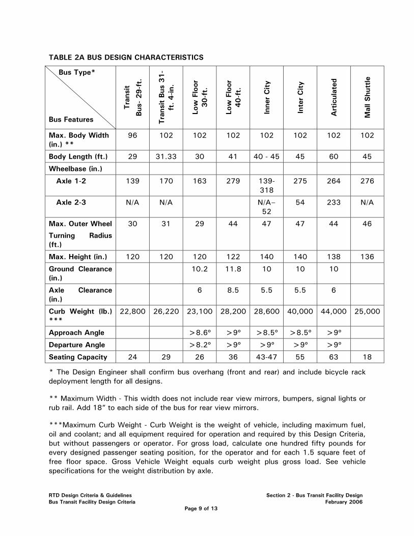
TABLE 2A BUS DESIGN CHARACTERISTICS
Bus Type*
Bus Features Tra
nsit
Bus
- 29-f
t.
Tra
nsit B
us 3
1-
ft.
4-in
.
Low
Flo
or
30-f
t.
Low
Flo
or
40-f
t.
Inne
r C
ity
Inte
r C
ity
Art
icul
ated
Mal
l Shu
ttle
Max. Body Width (in.) **
96 102 102 102 102 102 102 102
Body Length (ft.) 29 31.33 30 41 40 - 45 45 60 45
Wheelbase (in.)
Axle 1-2 139 170 163 279 139-318
275 264 276
Axle 2-3 N/A N/A N/A–52
54 233 N/A
Max. Outer Wheel
Turning Radius (ft.)
30 31 29 44 47 47 44 46
Max. Height (in.) 120 120 120 122 140 140 138 136
Ground Clearance (in.)
10.2 11.8 10 10 10
Axle Clearance (in.)
6 8.5 5.5 5.5 6
Curb Weight (lb.) ***
22,800 26,220 23,100 28,200 28,600 40,000 44,000 25,000
Approach Angle >8.6º >9º >8.5º >8.5º >9º
Departure Angle >8.2º >9º >9º >9º >9º
Seating Capacity 24 29 26 36 43-47 55 63 18
* The Design Engineer shall confirm bus overhang (front and rear) and include bicycle rack deployment length for all designs.
** Maximum Width - This width does not include rear view mirrors, bumpers, signal lights or rub rail. Add 18” to each side of the bus for rear view mirrors.
***Maximum Curb Weight - Curb Weight is the weight of vehicle, including maximum fuel, oil and coolant; and all equipment required for operation and required by this Design Criteria, but without passengers or operator. For gross load, calculate one hundred fifty pounds for every designed passenger seating position, for the operator and for each 1.5 square feet of free floor space. Gross Vehicle Weight equals curb weight plus gross load. See vehicle specifications for the weight distribution by axle.
RTD Design Criteria & Guidelines Section 2 - Bus Transit Facility Design Bus Transit Facility Design Criteria February 2006
Page 9 of 13
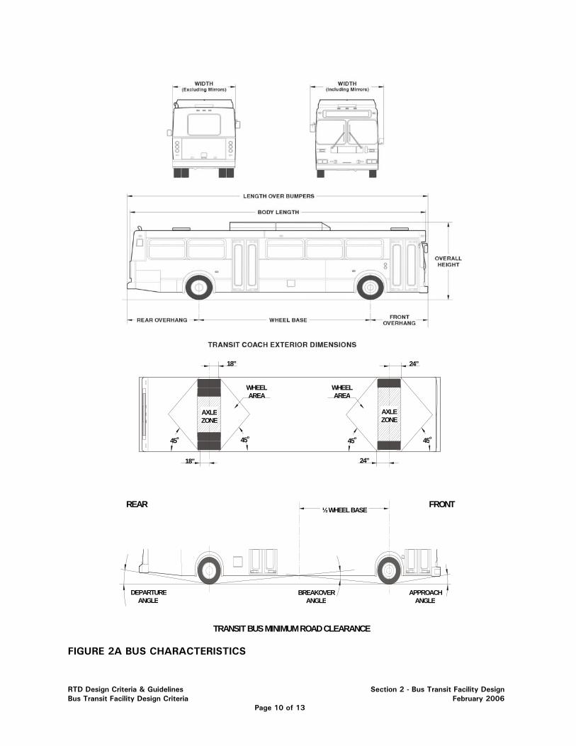
TRANSIT BUS MINIMUM ROAD CLEARANCE
REAR FRONT½ WHEEL BASE
18” 24”
24”18”
45o45o
WHEELAREA
WHEELAREA
45o 45o
DEPARTUREANGLE
APPROACHANGLE
BREAKOVERANGLE
AXLEZONE
AXLEZONE
FIGURE 2A BUS CHARACTERISTICS
RTD Design Criteria & Guidelines Section 2 - Bus Transit Facility Design Bus Transit Facility Design Criteria February 2006
Page 10 of 13
2.6.0 GRADE-SEPARATED PEDESTRIAN ACCESS
Grade separated pedestrian accesses will be constructed wherever pedestrian traffic traveling between elements of the transit system must be protected from vehicular traffic. In general, bridges are preferable to tunnel access because of security concerns. All accesses shall be designed in accordance with the most current version of ADAAG, or other local, more restrictive accessibility standards. Ramps, stairs and elevators shall be included in order to satisfy ADA requirements, emergency egress requirements and to provide convenient and efficient mobility between transit system elements. Elevators shall be capable of accommodating bicycles and emergency medical equipment (gurneys). Pedestrian bridges shall include enclosed walkways in order to protect the users from the weather. Grade separated accesses shall include provisions for periodic cleaning, maintenance and inspection of structural members. Grade separated access shall be designed with consideration of economical construction and maintenance. Design guidelines for grade-separated pedestrian access facilities are provided in Section 6 of this Manual.
2.7.0 PARK AND RIDE (pnR) DESIGN
Park-n-Rides (pnR) are provided for the use of transit patrons using personal vehicles to reach the transit system. A pnR should provide convenient facilities for access to the transit system and for transit patrons to leave personal vehicles long term.
Park-n-Rides are provided in locations as designated by RTD service planners or where indicated by specific corridor studies. Typical pnR locations are at light rail or commuter rail stations, adjacent to BRT stations and at locations that can be conveniently accessed by multiple local and express routes or by regional bus routes.
A pnR shall typically provide individually marked parking stalls and access drives, passenger pick-up and drop off facilities (kiss-n-Ride, short term parking), bus transfer facilities including bus bays for loading and unloading, a drivers relief station (DRS), shelters, benches, trash receptacles, bicycle parking, lighting, information kiosks, public telephones (pay and emergency) and security features. Facilities shall be paved, landscaped and designed to provide safe and convenient parking and bus transfer facilities for transit patrons. A pnR shall be designed with consideration for efficiency of use, economical site construction and convenient maintenance activities. The site design shall meet the requirements of the local jurisdiction.
2.7.1 Bus Transfer Areas
Bus transfer areas can be internal to the site or may be located at the edge of an adjacent roadway.
Where transfer facilities are located adjacent to the site on the local roadway system, bus pads shall be constructed in accordance with RTD Standard Drawings. The location of bus pads shall be coordinated with the local roadway authority.
RTD Design Criteria & Guidelines Section 2 - Bus Transit Facility Design Bus Transit Facility Design Criteria February 2006
Page 11 of 13
Where transfer areas are located on site, integrated with a pnR, bus transfer areas shall be separated wherever possible from parking areas so that bus traffic and private vehicle traffic do not share drive lanes. The bus waiting area shall be constructed with concrete pavement and concrete curb and gutter, and individual bus loading bays shall be designed in accordance with RTD Standard Drawings. The number of bus bays provided in the waiting area shall be as designated by RTD’s service development division.
Access to the bus transfer areas shall, wherever possible be located at signalized intersections. Two points of access shall be provided, if possible. All access shall be designed so that buses may enter and exit the transfer facility without reverse movement. Access to the site shall be coordinated with the local roadway authority. Bus access from the local roadway to the site shall be constructed with the use of curb returns or curb cuts, as required by local jurisdictions. The use of curb cuts shall be avoided. Curb return and drive lane minimum radii shall be designed in accordance with Section 3.7.9 of this Manual. Bus facility turning radii shall be designed for the radius of the most restrictive vehicle that could access the facility.
A DRS shall be located within a convenient distance (50 feet or less) from the bus waiting area, unless site constraints require a longer distance, which shall be coordinated with RTD.
Bus transfer area facilities, including site fixtures, pavement, lighting, DRS, utilities, bike facilities, drainage, and urban design and landscaping shall be designed in accordance with the appropriate sections of this Design Criteria and local requirements.
2.7.2 Parking Areas
Parking areas can be constructed as surface lots or as multi-story parking structures. Wherever possible, parking areas shall be constructed as surface lots. If parking demand is high and ROW is unavailable, parking structures shall be considered. For planning purposes, the designer shall assume a ratio of 75 parking spaces per acre for surface lots (see Section 1.1.0).
The pnR shall have access from public roadways from at least two locations. Full movement access must be available from at least one signalized intersection, if possible. Right-in-right-out (RI/RO) and three-quarter movements may be acceptable for additional access points. Drive lanes that mix bus traffic with private vehicle traffic shall be avoided. Site access shall be coordinated with the local roadway authority.
Parking areas shall be constructed of concrete or asphalt and shall include concrete curb and gutter. The type of pavement shall be based on recommendations from a geotechnical study or pavement design and as directed by RTD. See Section 3 of this Manual for site design standards. Parking area facilities, including pavement, lighting, security, drainage and
RTD Design Criteria & Guidelines Section 2 - Bus Transit Facility Design Bus Transit Facility Design Criteria February 2006
Page 12 of 13
landscaping shall be designed in accordance with the appropriate section of this Design Criteria and local requirements. See Section 6 of this Manual for parking structure criteria.
RTD Design Criteria & Guidelines Section 2 - Bus Transit Facility Design Bus Transit Facility Design Criteria February 2006
Page 13 of 13
SECTION 3 – CIVIL DESIGN 3.1.0 GENERAL ..................................................................................................... 3 3.2.0 SURVEY ....................................................................................................... 3 3.3.0 GEOTECHNICAL............................................................................................ 3
3.3.1 Pavement Design ................................................................................. 3 3.3.2 Soils and Foundation Investigations and Pavement Designs ....................... 5
3.4.0 DRAINAGE, EROSION CONTROL, WATER QUALITY .......................................... 6
3.4.1 General............................................................................................... 6 3.4.2 Hydrologic Criteria ............................................................................... 6 3.4.3 Hydraulic Criteria ................................................................................. 7 3.4.4 Storm Sewer....................................................................................... 7 3.4.5 Inlets.................................................................................................. 8 3.4.6 Detention Facilities............................................................................... 8 3.4.7 Permanent Water Quality Facilities ......................................................... 8 3.4.8 Erosion Control.................................................................................... 9
3.5.0 UTILITIES ..................................................................................................... 9
3.5.1 Water Service...................................................................................... 9 3.5.2 Sanitary Sewer.................................................................................. 10 3.5.3 Electrical........................................................................................... 10 3.5.4 Telephone and Communication Services ............................................... 10
3.6.0 SITE FURNISHINGS...................................................................................... 11 3.7.0 SITE LAYOUT ............................................................................................. 11
3.7.1 Access and Circulation ....................................................................... 11 3.7.2 Grading ............................................................................................ 12 3.7.3 Islands.............................................................................................. 13 3.7.4 Parking Stalls .................................................................................... 13 3.7.5 ADA Accessible Parking ..................................................................... 14 3.7.6 Motorcycle Parking ............................................................................ 14 3.7.7 Kiss-n-Ride (short-term parking) ........................................................... 14 3.7.8 Bus Bays and Saw Tooth Geometry ..................................................... 14 3.7.9 Internal Lane and Aisle Criteria ............................................................ 15 3.7.10 Plaza Layout...................................................................................... 15
3.8.0 ACCESSIBILITY STANDARDS ....................................................................... 15 3.9.0 ROADWAY IMPROVEMENTS ........................................................................ 16
RTD Design Criteria & Guidelines Section 3 – Civil Design Bus Transit Facility Design Criteria February 2006
Page 1 of 17
3.9.1 General............................................................................................. 16 3.9.2 Street Improvements .......................................................................... 16 3.9.3 Traffic Signals and Control Devices ...................................................... 16
3.10.0 SNOW STORAGE AREAS ........................................................................... 16
RTD Design Criteria & Guidelines Section 3 – Civil Design Bus Transit Facility Design Criteria February 2006
Page 2 of 17
SECTION 3 – CIVIL DESIGN
3.1.0 GENERAL
This Design Criteria establishes the minimum standards to be used in the design of RTD bus transit facilities. This section is intended to direct the Design Engineer in the civil engineering design at all RTD bus transit facilities.
3.2.0 SURVEY
An ALTA survey is required for all new facilities and expansions of existing ones, unless one already exists that is less than 2 years old or it is otherwise determined by RTD that none is required (i.e., small or limited service facilities for street-side stops). RTD’s minimum requirement from an ALTA Survey includes items 1-15 from Table A of the 2005 edition of ALTA/ACSM Land Title Survey, and shall include the following or additional items:
• Item #11 –Include locations horizontally and vertically for Storm Sewers (rims and inverts at manholes, inlets and outlets), Sanitary Sewers (rims and inverts at manholes), Gas Mains (potholed elevations), fiber optic lines (potholed elevations), water mains and appurtenances.
• Item #12 – Per the requirements of the local jurisdiction. • Include any other physical planimetric features including landscaping and fences,
and also topography, as stipulated, within fifty-(50) feet of the site. Topography shall include 1 foot contours and spot elevations as appropriate.
• Include easements, rights-of-way (ROW) and other jurisdictional, utility, RR or special district encumbrances.
The electronic format of the survey shall be in a matching project/world coordinate system, project base point and scale. RTD’s standard vertical datum is the North American Vertical Datum of 1988 (NAVD 88) and shall be used unless written permission has been received from RTD to use another datum.
3.3.0 GEOTECHNICAL
3.3.1 Pavement Design
A geotechnical investigation and pavement designs are required for new or expanded major facilities (i.e., pnR, BRT stops and transfer station) unless a relevant report acceptable to RTD already exists for the area under consideration. Pavement designs are required for both patron vehicle and bus loadings and shall include recommendations for both Portland Cement Concrete (PCC) and Hot Bituminous Pavement (HBP). Pavement designs shall be based on the 20 year 18,000 pound equivalent single axle load (18K ESAL). Pavement designs shall be prepared in accordance with the Metropolitan Government Pavement Engineers Council (MGPEC) criteria and shall include a life cycle cost analysis.
RTD Design Criteria & Guidelines Section 3 – Civil Design Bus Transit Facility Design Criteria February 2006
Page 3 of 17
Recommendations of “over excavating” for the subgrade preparation of surface parking areas that exceed 1 foot in depth should be avoided and alternative solutions explored. Subgrade preparation (i.e., moisture treatment, lime stabilization or other) in excess of 1 foot shall be evaluated on a case-by-case basis and alternative solutions shall be explored. In all cases the subgrade should be evaluated to determine its structural bearing capacity. Additional geotechnical investigations shall include determining “R” value, plastic/liquid limit and plasticity index (PL/LL/PI), shrink-swell potential and other applicable criteria based on site conditions.
Geotechnical investigations (including sampling frequencies) for pavement design purposes shall be conducted in accordance with MGPEC criteria.
There are three typical load carrying pavements at a facility:
• The first (heaviest load-carrying) pavement is for bus lanes and bays. To lessen pavement rolling and rutting, they shall be PCC 10-inch depth, or as recommended by a pavement design prepared by a registered Professional Engineer. All PCC pavements shall include curb and gutters that are monolithically poured and tied to the PCC pavement with dowels per RTD Standard Drawings. Pavement thicknesses less than 10” depth for bus lanes and bays shall be approved by RTD in writing.
• The second pavement type is for patron vehicle circulation or parking. It may be constructed with hot bituminous pavement (HBP) or PCC. PCC pavement is preferred, but HBP may be better for specific applications due to light reflectivity or cost considerations. The minimum circulation route pavement thickness is 8 inches, or as recommended by a pavement design prepared by a registered Professional Engineer.
• The third pavement shall be for walkway, plaza and other pedestrian areas. It shall be constructed with polypropylene fiber mesh reinforced PCC, 6-inch thick, capable of bearing maintenance and snow removal vehicles.
Concrete for PCC pavement shall be CDOT mix design class “P”, 4200 psi at 28 days. CDOT mix design class “B”, 3000 psi at 28 days may be used for walkways, plazas and curb and gutter with approval from RTD.
Hot bituminous pavement shall be in accordance with the MGPEC Pavement Design Standards and Construction Specifications. Generally, hot bituminous pavement grading “SX” should be used for the top lift of pavement and grading “S” for the lower lifts. The Design Engineer shall include a completed MGPEC Form 9 as part of the Technical Specifications for specifying hot bituminous pavement.
As allowed by local jurisdictions and directed by RTD, temporary parking lots may be paved with gravel, crusher fines or recycled materials. They shall be
RTD Design Criteria & Guidelines Section 3 – Civil Design Bus Transit Facility Design Criteria February 2006
Page 4 of 17
stabilized with a minimum 6-inch thick layer of compacted recycled asphalt. Temporary facilities may be excluded from the requirement of a geotechnical report and pavement design with approval from RTD.
All pavement subgrade shall be treated with a soil sterilant to inhibit future vegetative growth.
3.3.2 Soils and Foundation Investigations and Pavement Designs
A Professional Engineer shall prepare a foundation report for all pavements, structures and retaining walls, and gather appropriate information for a stable design, which, in addition to field work, shall include a review of preliminary structure plans, previous foundation reports, as-built plans and historic subsurface conditions information for the proposed structure area. The prior information review shall focus the analysis towards areas of concern before starting fieldwork.
A bore-hole plan approved by RTD shall be established on a site plan layout and shall be relative to proposed foundation, pavement or excavation locations. A drill crew shall collect undisturbed soil samples for laboratory testing and perform appropriate in-situ soil tests.
An engineer or geologist working under the direction and supervision of a registered Professional Engineer shall collect soil samples, perform in-situ and other manual field tests and observations, compile the results, document and record the data, and provide the necessary information to develop the project boring log and final geotechnical report. The report shall include geotechnical design recommendations based on the collected data. The report shall be signed and sealed by the registered Professional Engineer.
After completing the test borings log, the registered Professional Engineer shall analyze geotechnical surface and subsurface information, prepare a geotechnical report, as discussed above, and submit a signed and sealed copy to RTD, which shall include the recommended foundation type, and all pertinent geological foundation design parameters.
The report, at a minimum, shall include:
• Site conditions (current and historic) • Geologic conditions • Site investigations • Subsurface conditions • Recommendations • Limitations • Surficial geology • Surficial geology map legend • Plan location of exploratory bore holes
RTD Design Criteria & Guidelines Section 3 – Civil Design Bus Transit Facility Design Criteria February 2006
Page 5 of 17
• Bore-hole logs with depth and geologic stratigraphy • Legends and notes of exploratory borings • Ground water potential, depth and possible fluctuations • Summary of laboratory test results • Soil corrosiveness potential test results • Sulfide content • Swell compression test results • Gradation test results (sieve analysis) • R value • Liquid and Plastic Limits (LL and PL) • Plasticity Index (PI) • Moisture density relationships (dry density and optimum moisture
content) • AASHTO T-99, T-180 (modified and standard proctor applications) • Dewatering requirements and recommendations • Monitoring requirements and recommendations • Potential utility conflicts • Pavement Designs • Other items as determined for the specific site conditions
3.4.0 DRAINAGE, EROSION CONTROL AND WATER QUALITY
3.4.1 General
Drainage design shall be in accordance with the design standards and technical criteria of the local jurisdictional agency. Whenever the work is located within CDOT right-of-way, CDOT standards as specified in the CDOT Drainage Design Manual shall be followed. Where local jurisdictions have no codes or standards, the design standards and technical criteria provided in the Urban Drainage and Flood Control District’s (UDFCD) Urban Storm Drainage Criteria Manual (USDCM) and the CDOT Drainage Design Manual shall be used.
Storm water control and conveyance system design shall not impact adjacent properties upstream or downstream of RTD facilities beyond historic and legal allowances without consent and documented approval from adjacent property owners and governing jurisdictions.
Work within regulatory floodplains shall meet the requirements of the local jurisdiction and FEMA.
3.4.2 Hydrologic Criteria
Stormwater design flows shall be determined using methods specified by the design standards and technical criteria of the local jurisdiction. If no methods
RTD Design Criteria & Guidelines Section 3 – Civil Design Bus Transit Facility Design Criteria February 2006
Page 6 of 17
are specified, flows shall be determined using the Rational Method or the Colorado Urban Hydrograph Procedure and the Urban Drainage Storm Water Management Model as described in the USDCM, as applicable.
All bus transit facilities, including parking lots and roadway improvements shall be designed in accordance with the design storm frequencies as specified by the technical criteria of the local jurisdiction. If design storm frequencies are not specified, the minor storm system shall be designed for the 5-year storm and the major storm system shall be designed for the 100-year storm. CDOT criteria use only the 100-year storm for major highway crossings. Storm water design shall not impact adjacent properties upstream or downstream of RTD facilities. Drainage design shall consider flows from adjacent properties and shall be designed to accept historic flows from upstream areas. Where stormwater flows from upstream properties cross RTD facilities, the emergency overflow pathway through RTD facilities shall be evaluated and accounted for in site design. Storm sewers, culverts and inlets shall be designed to convey the typical 5-year minor design storm event, unless the local jurisdiction or unusual conditions require larger conveyance elements.
3.4.3 Hydraulic Criteria
All storm sewer, hydraulic structures and appurtenances shall be designed in accordance with the design standards and technical criteria of the local jurisdiction as modified by this design manual.
Stormwater shall be conveyed in a system that includes curb and gutter and storm sewer. Stormwater flows in gutter located adjacent to designated pedestrian walkways shall be minimized. The depth of flow in curb and gutter in the minor storm shall be a maximum of 6 inches to prevent inundation and damage to landscaped areas and other adjacent improvements.
3.4.4 Storm Sewer
Storm sewer shall be constructed with Class III reinforced concrete pipe (RCP). Where conditions will provide inadequate cover material or excessive structural loading is expected, the class of pipe shall be evaluated and upgraded, if required. Storm sewer crossing LRT shall be Class V RCP.
Pipe material other than concrete, including polyethylene, polyvinyl chloride (PVC) or ductile iron, shall not be used without prior approval from RTD. Area drains within landscaped areas may be constructed with polyethylene or PVC, if they do not cross beneath or drain paved areas and if they do not connect to concrete pipe upstream.
RTD Design Criteria & Guidelines Section 3 – Civil Design Bus Transit Facility Design Criteria February 2006
Page 7 of 17
3.4.5 Inlets
Type R inlets, as modified by RTD Standard Drawings, shall be used to collect stormwater from curbed areas in accordance with local jurisdictional requirements. Other types of inlets, including Type 13, Type C, slotted-veined grates and combination inlets, shall not be used without prior approval from RTD. Inlets shall be designed to accept design flows with no more than 6 inches of ponding over the inlet in the minor storm. The design ponding depth over inlets in the major storm shall not exceed 9 inches. Inlets shall be placed in sump conditions. The use of on-grade inlets shall be avoided. In public right-of-way, published jurisdictional standards shall take precedence.
Inlet grates in pedestrian areas shall be heel-proof and non-slip, and shall meet all requirements of the ADAAG.
Any structures that vary from agency or RTD standards, including manholes, junction boxes, inlets, vaults or other structures shall require prior approval by RTD.
3.4.6 Detention Facilities
Detention facilities shall be provided as required by the local jurisdiction, and shall be designed in accordance with the design standards and technical criteria of the local jurisdiction and Urban Drainage and Flood Control District (UDFCD). Rip-rap, cobbles or other similarly rocky material used for landscaping, erosion control or storm drainage management shall be designed to prevent vandalism. This may include the use of grout, top-soil cover, large or heavy stones, which preclude manual lifting or other agreed upon alternatives. RTD approval shall be obtained prior to specifying these materials. Detention ponding for the 10-year frequency storm shall not extend into parking or other paved areas. Detention ponding may extend into parking areas to a depth of 9 inches in a 100-year storm event, if allowed by the design standards and technical criteria of the local jurisdiction. Detention ponding shall not extend into designated pedestrian routes. Underground detention shall not be used unless approved by RTD and the local jurisdiction. Detention pond outlet structures shall be designed in accordance with RTD Standard Drawings.
3.4.7 Permanent Water Quality Facilities
Permanent water quality facilities shall be provided unless the site is served by regional water quality facilities with adequate capacity for the proposed construction. Water quality facilities shall be integrated into the detention pond. Facilities shall be designed in accordance with the design standards of the USDCM Volume 3. They shall not be designed to have a permanent pool of water.
RTD Design Criteria & Guidelines Section 3 – Civil Design Bus Transit Facility Design Criteria February 2006
Page 8 of 17
Water quality facilities requiring special maintenance provisions (including facilities constructed with underground vaults) shall not be used unless approved by RTD.
3.4.8 Erosion Control
Facility design shall include provisions for erosion control Best Management Practices (BMPs) during construction. BMPs shall be designed in accordance with the design standards and technical criteria of the local jurisdiction. The use of rip-rap or cobbles shall be in accordance with part 3.4.6 of this Manual. If the local jurisdiction does not specify erosion control design standards, guidelines or criteria, then BMPs shall be used in accordance with the USDCM Volume 3.
3.5.0 UTILITIES
3.5.1 Water Service
The size of the water service taps and meters shall be determined by the demand for both irrigation and domestic uses on site. The cost of the water and sewer taps and post-construction service rates shall be analyzed, and the most economical combination of domestic and irrigation water taps, and sanitary sewer service taps shall be purchased for the site from the local utility district. In some cases, it may be more economical to purchase a separate irrigation tap.
Water service shall be provided to the Drivers Relief Station (DRS) building. The service line shall be constructed in accordance with local criteria. If local criteria do not specify service line requirements, service lines shall be constructed with ¾ inch Type K copper. If a DRS is located more than 50-feet from the water main line, the water service line shall be analyzed for head losses using the American Water Works Association manual Sizing Water Service Lines and Meters (M22). The size of the service line shall be increased as required after the water meter without increasing the tap size.
Generally facility development will not require the construction of utility main lines. If the construction of utility mains is required, utilities main lines shall be constructed in accordance with the standards and criteria of the local utility district. All water mains and service lines shall be buried to a minimum 4.5 foot depth. Excessive burial depths shall be avoided.
Where community water service is not available to the site, a domestic well may be constructed. The design of water well facilities, if required, shall be coordinated with RTD on a case-by-case basis. State permitting and adjudication requirements shall be coordinated with the State Engineer’s Office, and the Colorado Department of Public Health and Environment, as required.
RTD Design Criteria & Guidelines Section 3 – Civil Design Bus Transit Facility Design Criteria February 2006
Page 9 of 17
If a 1 inch or larger water tap is required for irrigation or other purposes, consideration should be given to installing a 1 inch water service line into the DRS for the purpose of using a tank-less toilet. However, if no other need besides a tank-less toilet exists for a 1 inch waterline tap, a ¾ inch tap and a regular tank toilet shall be used. Utility trench backfill shall adhere to street compaction and materials requirements as defined by local jurisdiction criteria.
3.5.2 Sanitary Sewer
Sanitary sewer service shall be provided to the DRS. Service lines shall be constructed in accordance with the design standards of the local utility district. Where local criteria do not specify service line requirements, service lines shall be constructed with 4 inch schedule 40 PVC. Service lines shall be installed with a minimum of 4.5 feet of compacted cover below the ground surface, and shall be installed at a minimum slope of 2% between the DRS and the utility main line, unless topographic constraints require a reduced slope and as approved by RTD.
Generally, facility development will not require the construction of utility main lines. If utility mains are required, they shall be designed and constructed in accordance with the local utility district standards and criteria. Utility trench backfill shall adhere to street compaction and materials requirements as defined by local jurisdiction criteria.
If community sanitary sewer service is not available, alternate waste disposal facilities (self contained DRS) may be constructed. The design of alternate facilities shall be coordinated with RTD, the Colorado Department of Public Health and Environment, Tri-County Health Department, local County Health Departments and local jurisdiction as required.
3.5.3 Electrical
Site electrical service shall be constructed in accordance with Section 9 of this Manual. The designer shall coordinate with the electrical service provider to install any conduits or utility sleeves that may be required in order to provide service to the site.
3.5.4 Telephone and Communication Services
The local service provider in coordination with RTD shall provide telephone service at all major facilities. Smaller street stops are excluded, unless otherwise warranted. The Design Engineer shall coordinate with the local service provider to locate utility sleeves or conduits to provide service to the site.
A minimum of one public pay phone, as coordinated with the local service provider, shall be provided. Phones shall be placed in a well lit portion of the
RTD Design Criteria & Guidelines Section 3 – Civil Design Bus Transit Facility Design Criteria February 2006
Page 10 of 17
passenger plaza waiting area, preferably adjacent to the main pedestrian pathways. Construction sequencing and phasing typically require the contractor to install only the phone conduit and respective pull cord, “mule” rope or tape.
Emergency telephones shall be installed as outlined in Section 12 of this Manual.
Video surveillance and associated equipment, conduits, duct-banks, pull boxes and appurtenances shall be installed as outlined in Section 12 of this Manual.
Communications service to the DRS shall be coordinated with the local service provider to include a minimum 24-pair phone cable. See Section 7 for DRS communications service design criteria. See Section 4 for the irrigation systems communications (remote monitoring) requirements.
3.6.0 SITE FURNISHINGS
Site furnishings (benches, trash receptacles, newspaper racks, etc.) shall be specified and installed in accordance with Section 4 of this Manual and RTD Standard Drawings. The designer shall coordinate with local jurisdictions to assure that both local and RTD design criteria are met.
3.7.0 SITE LAYOUT
While each facility project has its own unique set of design objectives and constraints and must be looked at on a case-by-case basis, there are certain design parameters that should be adhered to in order to achieve a proper design that is consistent with RTD requirements.
3.7.1 Access and Circulation
Bus, pedestrian and private vehicle access onto and through the site should be separated. There should be at least two separate and distinct points of private vehicle ingress and full movement egress that are separate from the bus and pedestrian movements. If this is not feasible, the Design Engineer shall coordinate site access with RTD. The exits and entrances should be located on different streets; however, if site conditions require that they be located on the same street, refer to the local jurisdictions design standards for the minimum separation and further coordinate with RTD. Circulation aisles shall be considered for park-n-Rides (pnRs) in excess of 200 spaces and should be located at the periphery of the parking area to minimize pedestrian and vehicle conflicts. One-way circulation or parking aisles are discouraged.
RTD Design Criteria & Guidelines Section 3 – Civil Design Bus Transit Facility Design Criteria February 2006
Page 11 of 17
3.7.2 Grading
Local topography shall influence the grading of a site. To ensure functionality of the site, the following grading parameters shall apply. A 1.5 to 2.0% grade is the most desirable for bus lanes. The allowable grade for parking stalls, circulation and access aisles shall be 1.0% (min.) and 5.0% (max.) Mountainous terrain grades for circulation aisles may utilize a maximum 8% grade. Bus access grades shall not exceed 4%. The parking stalls and access aisles for ADA accessible parking shall not exceed a 2% grade.
Horizontal and vertical control and grading shall be shown, measured and designed to curb and gutter flow lines rather than to the top back of curb or any other design feature. Spot elevations shall be shown at all significant surface locations such as plaza areas, walkways, stairs, curb returns, drive cuts, surface drainage features, exposed pipe inverts, swales, pans, gutters, structural elements, finished floor, top and bottom of walls, slopes, and all locations that are designed with minimum or maximum grades, major or minor elevation changes, and areas that are crowded with many graphic elements, numerous lines, tight contours and a variety of functional features.
All travel way (pedestrian or vehicular) slopes shall include gradient percents shown on the drawings. All non-travel way natural, landscaped, cut, fill or existing slopes shall include horizontal to vertical (H:V) grade ratios shown on the drawings. Both travel and non-travel slopes shall include directional arrows showing “+” (up-slopes) and “--“ (down-slopes) relative to stationing, as applicable. Emphasis shall be placed on all access locations, curb returns, drive lanes, walkways, bike-ped paths, ramps, landscaped areas, drainage swales, side-slopes, ridges and all features with grades that are less than or greater than the limits of 1% to 3%.
In general, grading for landscape areas should not exceed a slope of 3:1 (H:V) and shall be used only to minimize retaining walls or to maximize adjacent non-landscaped areas. The preferred maximum cut, fill, natural or landscaped slope is 4:1 (H:V). See Section 4, Urban Design and Architectural Elements, for additional criteria about grading in landscape areas.
Parking aisles should be aligned parallel to the primary direction of pedestrian flow. When the topography of the land or site conditions require grades in the facility to exceed 3%, consideration should be given to aligning parking stalls perpendicular to the grade of the lot.
Passenger boarding zones are defined as the area directly adjacent to the bus bay where passengers queue for buses. Passenger boarding zones shall be located on a defined accessible route of travel, which should be the shortest possible route to the ADA accessible parking spaces. The grades
RTD Design Criteria & Guidelines Section 3 – Civil Design Bus Transit Facility Design Criteria February 2006
Page 12 of 17
within the passenger boarding zones and the ADA accessible parking spaces should have a minimum slope of 1.0% and may not exceed 2.0% in any direction. Accessible routes shall include ramps and handrails as required by ADA and ADAAG.
Passenger boarding zones are usually located adjacent to plaza areas, which are relatively broad areas that accommodate pedestrian pass thru and passenger waiting sites, often with shelters. Plaza areas shall be relatively flat and, excluding the passenger boarding zones, shall not exceed a 1.0% minimum and 2.0% maximum allowable grade in any direction. A pnR design should have grades that do not exceed 2.0% in any direction for the passenger boarding zones, plaza areas and the defined accessible route of travel. The grades of the bus bay, the adjacent passenger boarding zones and plaza areas need to be reviewed in conjunction with each other to assure that a situation has not been created that interferes with use of the wheel chair lifts on the buses. The walking distance from the plaza area to the most distant parking stall should not exceed 1000 feet and shall not exceed 1500 feet without RTD approval.
3.7.3 Islands
A raised island, typically 10 feet (may be reduced if other constraints prevail) wide (FL to FL), should be placed at the ends of each parking row to provide adequate sight distance, aesthetic appearance and meet jurisdictional requirements. The use of painted islands in lieu of a raised island with curb and gutter is discouraged and requires RTD approval. However, if a painted island is used, the width should not exceed 4 feet in order to discourage its use as a parking space.
3.7.4 Parking Stalls
Standard parking stall dimensions are 9 feet wide by 18 feet deep. RTD does not normally use compact parking stalls at surface lots, however if site constraints require reduce depths, and the parking spaces are adjacent and perpendicular to a curb, and sufficient depth is available behind the curb, the stall depth can be reduced by 2 feet to 16 feet. If this configuration is used, a 2 foot paved platform behind the curb shall be included to lessen landscape maintenance restrictions. The curb head height for a 16 feet deep parking stall shall not exceed 6 inches. Reduced depth parking stalls are only allowable when permitted by the local jurisdiction and approved by RTD.
Parking stall widths may be reduced to 8.5 feet within a parking structure and shall include double striping. The length of parking stalls within a structure shall be 18 feet. Double striping shall include two 4 inch wide stripes placed 12” on center on both sides. Standard striping may be used within parking structures with approval from RTD.
RTD Design Criteria & Guidelines Section 3 – Civil Design Bus Transit Facility Design Criteria February 2006
Page 13 of 17
See Section 5 for bicycle parking criteria.
3.7.5 ADA Accessible Parking
ADA accessible parking and access shall conform to the ADAAG.
3.7.6 Motorcycle Parking
The number of spaces that should be dedicated for motorcycle parking is unique to each location and shall be determined by demographics and the size of the facility. During conceptual design, a ratio of motorcycle parking to automobile parking shall be 1 to 50 respectively.
See the RTD Standard Drawings for the layout of motorcycle parking. Motorcycle parking can damage asphalt pavement, therefore concrete pavement shall be used for motorcycle parking spaces.
3.7.7 Kiss-n-Ride (short-term parking)
The use of kiss-n-rides should be considered for all pnR facilities. Their parking stalls should face and be located near bus loading zones or rail platforms. Locate kiss-n-ride parking stalls near the ADA parking area. The number of kiss-n-ride spaces is unique to each location, as determined by area demographics and ridership and will be as directed by RTD.
Signage indicating that the stall shall be used only as a kiss-n-Ride or a sign limiting the time, typically 15 minutes should be used.
3.7.8 Bus Bays and Saw Tooth Geometry
The standard parallel dimensions for bus loading bays are nominally 12 feet by 50 feet for 45 feet long buses, and 12 feet by 70 feet for an articulated bus. The standard access taper is 7:1, and egress taper is 4:1. Refer to RTD Standard Drawings for additional geometric layout information.
RTD Design Criteria & Guidelines Section 3 – Civil Design Bus Transit Facility Design Criteria February 2006
Page 14 of 17
3.7.9 Internal Lane and Aisle Criteria
Orthogonal parking is the preferred geometry for stalls, curbs and circulation lanes.
As required by limited space, angled (e.g. 45 degrees) parking will be considered on a case-by-case basis in coordination with RTD during the concept design phase. When angled parking is used, aisle direction and width shall be one-way and 15 feet (for 45 degree parking), respectively.
The following acceptable and desirable drive lane widths and curb return FL radii shall apply to two-way drive lanes/aisles:
• Parking Aisle o width – 24 feet minimum o radius – 2 feet minimum, 5 feet desirable
• Circulation Aisle o width – 24 feet minimum, 30 feet desirable o radius – 15 feet minimum
• Bus lane o width – 30 feet minimum o radius – 35 feet minimum o Turn lane – 30 feet minimum (inner) o Turn lane – 55 feet minimum (outer) o Turnaround – 65 feet minimum (outer)
3.7.10 Plaza Layout
The layout of the plaza areas shall be coordinated with local jurisdictions to assure that both local and RTD design criteria are met. Refer to Section 4, Urban Design, Architectural Landscape Elements.
3.8.0 ACCESSIBILITY STANDARDS
Specific attention shall be given to the most recent version of the Americans with Disabilities Act (ADA), the ADA Accessibility Guidelines for Building and Facilities (ADAAG), the ADA Accessibility Guidelines for Transportation Vehicles and to any supplements that may be issued. Their applicability is noted in several sections of this Manual where apparent or appropriate significance apply. ADA adherence is required for all areas of this Manual, regardless of explicit, implied or lack of reference herein.
RTD Design Criteria & Guidelines Section 3 – Civil Design Bus Transit Facility Design Criteria February 2006
Page 15 of 17
3.9.0 ROADWAY IMPROVEMENTS
3.9.1 General
Based on the requirements of the local jurisdictional authority or site traffic analysis findings, adjacent street improvements shall be designed to accommodate additional traffic accessing proposed bus transit facilities. Such improvements may include turn lanes or a traffic signal, for example. Since these improvements are most likely to be on public right of way, they shall be designed in close coordination with the local jurisdiction.
3.9.2 Street Improvements
Unless otherwise specified, all road and street design shall be in accordance with the current specifications and design guidelines of the local jurisdictions. For those cases where the local jurisdictions have no design guidelines, the most current versions of the Colorado Department of Transportation (CDOT) Design Guide, and/or the Policy on Geometric Design of Highways and Streets by the American Association of State Highway and Transportation Officials (AASHTO) shall be used and coordinated with RTD design staff.
3.9.3 Traffic Signals and Control Devices
Traffic signals and control devices shall be designed in accordance with local jurisdiction criteria and the Manual on Uniform Traffic Control Devices (MUTCD). The design shall be based on a traffic study and coordinated with the local jurisdiction to ensure compatibility with adjacent traffic signals and traffic patterns. The power source for the signal shall be coordinated with the local utility provider and jurisdiction. When possible, existing easements should be utilized for location of the power service. New easements should be avoided where feasible.
3.10.0 SNOW STORAGE AREAS
The Design Engineer shall consider snow removal procedures, maneuvering requirements, and storage for walkways, plazas, roads, drives and parking lots. Designated snow storage areas shall be provided at all RTD bus transit facilities and shall be located within or directly adjacent to areas requiring snow removal. Snow storage areas shall be sized to equal 10% of the areas requiring snow removal, which is based on a design storm of 6 inches and a pile height of 5 feet, excluding consolidation of snow. For larger storms, snow storage will be coordinated with RTD.
Snow storage areas shall be located down gradient and in the vicinity of storm water collection and conveyance features such as curb and gutter, inlets, curb cuts, swales, detention ponds and broad grassy landscaped areas. Locate storage areas to protect structures, roadways, parking lots, walkways or plazas from snow melt runoff. The
RTD Design Criteria & Guidelines Section 3 – Civil Design Bus Transit Facility Design Criteria February 2006
Page 16 of 17
Design Engineer shall coordinate the location of snow storage areas with landscaping design so that landscaping is not damaged during snow removal and storage.
Designated snow storage areas shall not impact parking, bus bays, pedestrian traffic or vehicular circulation. Parking areas for snow storage shall be considered on a case by case basis and used only upon receiving written RTD approval.
RTD Design Criteria & Guidelines Section 3 – Civil Design Bus Transit Facility Design Criteria February 2006
Page 17 of 17
SECTION 4 – URBAN AND LANDSCAPE DESIGN ELEMENTS
4.1.0 GENERAL...................................................................................................... 2 4.2.0 LANDSCAPING.............................................................................................. 2
4.2.1 Landscaping Requirement and Ordinances ...................................................... 2 4.2.2 Crime Prevention Through Environmental Design ............................................. 2 4.2.3 Xeriscape Principals ..................................................................................... 2 4.2.4 Standard Landscape Elements ....................................................................... 4 4.2.5 Standard List of Landscape Plant Material....................................................... 4 4.2.3 Turf and Native Grasses ............................................................................... 9 4.2.4 Maintenance Standards ................................................................................ 9
4.3.0 IRRIGATION.............................................................................................. 10
4.3.1 Standard Irrigation Components .................................................................. 10 4.3.2 Remote Control Equipment ......................................................................... 11 4.3.3 Watering Restrictions and Watering Requirements ......................................... 11 4.3.4 Maintenance Standards .............................................................................. 11
4.4.0 SHELTERS................................................................................................ 12
4.4.1 Standard Shelter Design ............................................................................. 12 4.4.2 Custom Shelter Design............................................................................... 12
4.5.0 FURNITURE AND FIXTURES .......................................................................... 12
4.5.1 General .................................................................................................... 12 4.5.2 Benches ................................................................................................... 12 4.5.3 Trash Receptacles ..................................................................................... 13 4.5.4 Public Telephones...................................................................................... 13 4.5.5 Newspaper Racks ...................................................................................... 13 4.5.6 Food Vending Machines ............................................................................. 14 4.5.7 Bike Lockers and Racks .............................................................................. 14
4.6.0 HARDSCAPE............................................................................................. 14
4.6.1 Design Objective ....................................................................................... 14 4.6.2 Access to Pedestrian Areas ........................................................................ 14
4.7.0 ART-N-TRANSIT........................................................................................ 15
4.7.1 Art Selection Process................................................................................. 15
RTD Design Criteria & Guidelines Section 4 - Urban and Landscape Design Elements Bus Transit Facility Design Criteria February 2006
Page 1 of 16
SECTION 4 – URBAN AND LANDSCAPE DESIGN ELEMENTS
4.1.0 GENERAL
This Design Criteria establishes the minimum standards to be used in the design of RTD bus transit facilities. This section is intended to direct the Design Engineer in the design of urban design elements at all RTD bus transit facilities.
4.2.0 LANDSCAPING
4.2.1 Landscaping Requirement and Ordinances
Most governing agencies within the Regional Transportation District have landscape requirements or ordinances that dictate the amount and type of landscaping to be accomplished on a particular site. Each jurisdiction has its own requirements, however, all require live plant material be used in the facility design. Landscaping of facilities is desirable for aesthetic as well as ecological reasons and should consist of plantings that will be compatible with the operation of the facility. Generally trees will be placed on plaza areas and not on adjacent station platforms. The placement of trees in tree grates is discouraged due to the difficulty of maintaining these plants over a long period of time. Trees and shrubs in plaza areas shall be installed in planting beds. An area with a well maintained landscape is perceived as being safer than those which are bare of vegetation. Plants are to be used for screening neighboring land uses and to enhance the appearance and feel of the facilities. Trees planted in hardscape plaza or pedestrian areas should be installed in planters in lieu of tree grates wherever possible. Planter areas should include a raised curb to reduce the amount of snow melting agents being pushed into planting areas.
Landscape area slopes that are planted with sod or seed shall not exceed a 3:1 (H:V) gradient so that safe, convenient and efficient mowing and other maintenance operations can occur. The preferred slope is 4:1 (H:V) or flatter if not controlled by limited area or other site constraints.
4.2.2 Crime Prevention Through Environmental Design
The design shall incorporate Crime Prevention Through Environmental Design (CPTED) strategies to the entire design. Refer to Section 12.12.0 for CPTED guidelines.
4.2.3 Xeriscape Principals
Planning and Design
Planning and design of the site is critical to identify watering zone requirements and to determine soil types as well as to identify which locations are the most extreme for plant survival. Parking facilities are
RTD Design Criteria & Guidelines Section 4 - Urban and Landscape Design Elements Bus Transit Facility Design Criteria February 2006
Page 2 of 16
particularly difficult as the plants are primarily installed in locations that are surrounded by reflective hard surfaces, steep slopes or along roadways where exhaust fumes are a constant.
Soil Improvement
Proper soil preparation is the key to successful water conservation. If the soil is sandy, water and nutrients will be lost due to leaching below the root zone. If the soil is heavy clay, water will be lost through runoff. Heavy clay soils tend to repel surface water resulting in runoff. The water that does get into these soils is held so tightly by the clay itself that plants cannot use it. Plants in a clay soil, even though moist often tend to wilt from lack of moisture. Plant roots also need air to thrive. In clay soils, air spaces are small and may fill with water, so plants suffer from oxygen starvation.
In very sandy soils, the opposite is true. Sandy soils have very large pore spaces. Because the particles are large, there is little surface area to hold the water, so sandy soils tend to lose water rapidly.
Efficient Irrigation
Proper irrigation practices can lead to significant water savings. Different plant types should be watered with different irrigation zones. The system needs to be designed to fit the landscape, minimizing overlap onto streets, sidewalks and parking areas. Plant types need to be installed in zones that have similar water needs. This will optimize the irrigation system, saving significant amounts of water. Drip zones are to be used in locations that are shrubs and trees only.
Zoning of Plants
Plants of similar water use requirements need to be grouped together to take advantage of water savings. Selecting plants that will do well depending on the site exposure is also important. The use of the most water conserving plants on south and western slopes and those that require more moisture can be placed close to drainage ways and low lying areas. Grouping plants appropriately will minimize water waste.
Mulches
Mulching helps keep plant roots cool, prevents soil from crusting, minimizes evaporation and reduces weed growth. Organic mulches such as shredded cedar should be placed 4 inch thick. Inorganic mulches and landscape/geotextile fabrics are generally not used at RTD facilities.
RTD Design Criteria & Guidelines Section 4 - Urban and Landscape Design Elements Bus Transit Facility Design Criteria February 2006
Page 3 of 16
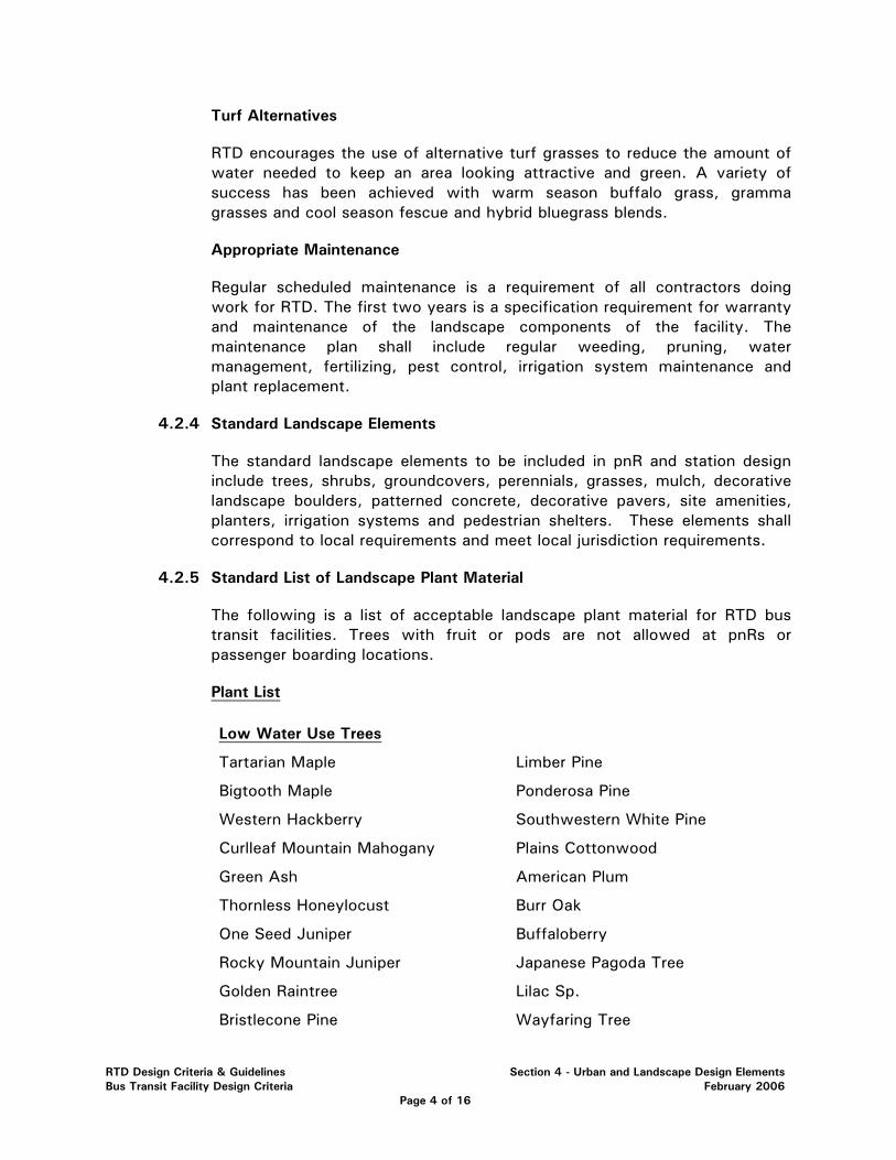
Turf Alternatives
RTD encourages the use of alternative turf grasses to reduce the amount of water needed to keep an area looking attractive and green. A variety of success has been achieved with warm season buffalo grass, gramma grasses and cool season fescue and hybrid bluegrass blends.
Appropriate Maintenance
Regular scheduled maintenance is a requirement of all contractors doing work for RTD. The first two years is a specification requirement for warranty and maintenance of the landscape components of the facility. The maintenance plan shall include regular weeding, pruning, water management, fertilizing, pest control, irrigation system maintenance and plant replacement.
4.2.4 Standard Landscape Elements
The standard landscape elements to be included in pnR and station design include trees, shrubs, groundcovers, perennials, grasses, mulch, decorative landscape boulders, patterned concrete, decorative pavers, site amenities, planters, irrigation systems and pedestrian shelters. These elements shall correspond to local requirements and meet local jurisdiction requirements.
4.2.5 Standard List of Landscape Plant Material
The following is a list of acceptable landscape plant material for RTD bus transit facilities. Trees with fruit or pods are not allowed at pnRs or passenger boarding locations.
Plant List
Low Water Use Trees
Tartarian Maple Limber Pine
Bigtooth Maple Ponderosa Pine
Western Hackberry Southwestern White Pine
Curlleaf Mountain Mahogany Plains Cottonwood
Green Ash American Plum
Thornless Honeylocust Burr Oak
One Seed Juniper Buffaloberry
Rocky Mountain Juniper Japanese Pagoda Tree
Golden Raintree Lilac Sp.
Bristlecone Pine Wayfaring Tree
RTD Design Criteria & Guidelines Section 4 - Urban and Landscape Design Elements Bus Transit Facility Design Criteria February 2006
Page 4 of 16
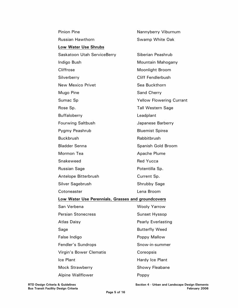
Pinion Pine Nannyberry Viburnum
Russian Hawthorn Swamp White Oak
Low Water Use Shrubs
Saskatoon Utah ServiceBerry Siberian Peashrub
Indigo Bush Mountain Mahogany
Cliffrose Moonlight Broom
Silverberry Cliff Fendlerbush
New Mexico Privet Sea Buckthorn
Mugo Pine Sand Cherry
Sumac Sp Yellow Flowering Currant
Rose Sp. Tall Western Sage
Buffaloberry Leadplant
Fourwing Saltbush Japanese Barberry
Pygmy Peashrub Bluemist Spirea
Buckbrush Rabbitbrush
Bladder Senna Spanish Gold Broom
Mormon Tea Apache Plume
Snakeweed Red Yucca
Russian Sage Potentilla Sp.
Antelope Bitterbrush Current Sp.
Silver Sagebrush Shrubby Sage
Cotoneaster Lena Broom
Low Water Use Perennials, Grasses and groundcovers
San Verbena Wooly Yarrow
Persian Stonecress Sunset Hyssop
Atlas Daisy Pearly Everlasting
Sage Butterfly Weed
False Indigo Poppy Mallow
Fendler’s Sundrops Snow-in-summer
Virgin’s Bower Clematis Coreopsis
Ice Plant Hardy Ice Plant
Mock Strawberry Showy Fleabane
Alpine Wallflower Poppy
RTD Design Criteria & Guidelines Section 4 - Urban and Landscape Design Elements Bus Transit Facility Design Criteria February 2006
Page 5 of 16
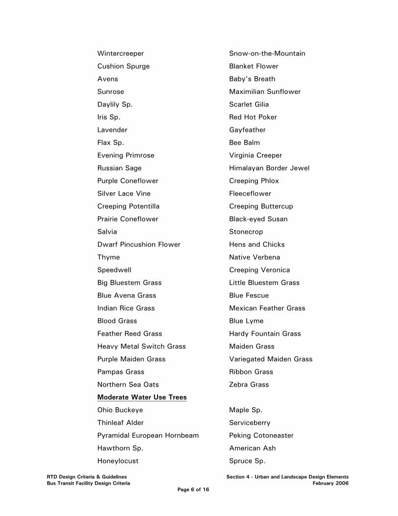
Wintercreeper Snow-on-the-Mountain
Cushion Spurge Blanket Flower
Avens Baby’s Breath
Sunrose Maximilian Sunflower
Daylily Sp. Scarlet Gilia
Iris Sp. Red Hot Poker
Lavender Gayfeather
Flax Sp. Bee Balm
Evening Primrose Virginia Creeper
Russian Sage Himalayan Border Jewel
Purple Coneflower Creeping Phlox
Silver Lace Vine Fleeceflower
Creeping Potentilla Creeping Buttercup
Prairie Coneflower Black-eyed Susan
Salvia Stonecrop
Dwarf Pincushion Flower Hens and Chicks
Thyme Native Verbena
Speedwell Creeping Veronica
Big Bluestem Grass Little Bluestem Grass
Blue Avena Grass Blue Fescue
Indian Rice Grass Mexican Feather Grass
Blood Grass Blue Lyme
Feather Reed Grass Hardy Fountain Grass
Heavy Metal Switch Grass Maiden Grass
Purple Maiden Grass Variegated Maiden Grass
Pampas Grass Ribbon Grass
Northern Sea Oats Zebra Grass
Moderate Water Use Trees
Ohio Buckeye Maple Sp.
Thinleaf Alder Serviceberry
Pyramidal European Hornbeam Peking Cotoneaster
Hawthorn Sp. American Ash
Honeylocust Spruce Sp.
RTD Design Criteria & Guidelines Section 4 - Urban and Landscape Design Elements Bus Transit Facility Design Criteria February 2006
Page 6 of 16

Lodgepole Pine Scotch Pine
Cottonwood Sp. Douglas Fir
Pear Sp. English/Red/White Oak
Pagodatree Japanese Tree Lilac
Greenspire Linden Blackhaw Viburnum
Crabapples Emerald Queen Maple
Norway Columnar Maple
Moderate Water Use Shrubs
Ginnala Maple Thin Leaf Alder
Shadblow Serviceberry Barberry
Butterfly Bush Quince
Smokebush Cotoneaster
Euonymous Sp. Beauty Bush
Privet Honeysuckle ‘tartarica’
Oregon Grape Holly Ninebark Sp.
Pyracantha Buckthorn
False Spirea Weigela
Cranberry Viburnum Carol Makie Daphne
Arnold Dwarf Forsythia Comp. Oregon Grape Holly
Lodense Privet Snowberry
Coralberry Spirea
Dwarf Cranberrybush Viburnum Hibiscus, Disco Belle
Moderate Water Use Perennials, Grasses and Groundcovers
Bishop’s Weed Lebanon Stonecress
Bugle Weed Lady’s Mantle
Mountain Basket of Gold Windflower
Golden Marguerite Columbine
Rockcress Sea Pinks
Aster Basket of Gold
Miniature Mat Daisy Bergenia
Snowbank Boltonia False Forget-me-not
Trumpet Vine Pigmy Peashrub
Cupids Dart Hardy Bachelor Button
RTD Design Criteria & Guidelines Section 4 - Urban and Landscape Design Elements Bus Transit Facility Design Criteria February 2006
Page 7 of 16
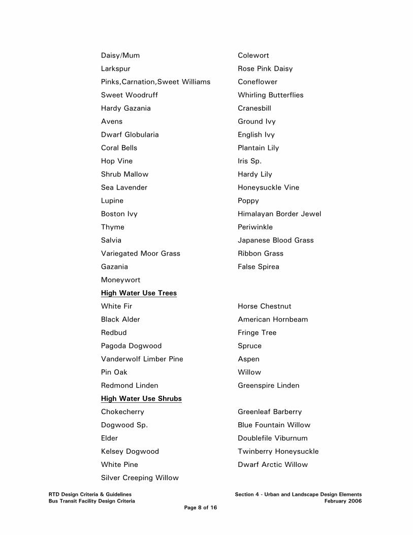
Daisy/Mum Colewort
Larkspur Rose Pink Daisy
Pinks,Carnation,Sweet Williams Coneflower
Sweet Woodruff Whirling Butterflies
Hardy Gazania Cranesbill
Avens Ground Ivy
Dwarf Globularia English Ivy
Coral Bells Plantain Lily
Hop Vine Iris Sp.
Shrub Mallow Hardy Lily
Sea Lavender Honeysuckle Vine
Lupine Poppy
Boston Ivy Himalayan Border Jewel
Thyme Periwinkle
Salvia Japanese Blood Grass
Variegated Moor Grass Ribbon Grass
Gazania False Spirea
Moneywort
High Water Use Trees
White Fir Horse Chestnut
Black Alder American Hornbeam
Redbud Fringe Tree
Pagoda Dogwood Spruce
Vanderwolf Limber Pine Aspen
Pin Oak Willow
Redmond Linden Greenspire Linden
High Water Use Shrubs
Chokecherry Greenleaf Barberry
Dogwood Sp. Blue Fountain Willow
Elder Doublefile Viburnum
Kelsey Dogwood Twinberry Honeysuckle
White Pine Dwarf Arctic Willow
Silver Creeping Willow
RTD Design Criteria & Guidelines Section 4 - Urban and Landscape Design Elements Bus Transit Facility Design Criteria February 2006
Page 8 of 16
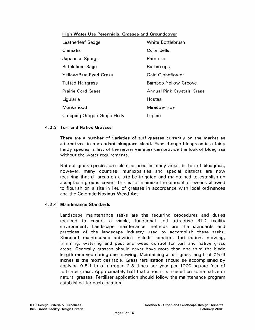
High Water Use Perennials, Grasses and Groundcover
Leatherleaf Sedge White Bottlebrush
Clematis Coral Bells
Japanese Spurge Primrose
Bethlehem Sage Buttercups
Yellow/Blue-Eyed Grass Gold Globeflower
Tufted Hairgrass Bamboo Yellow Groove
Prairie Cord Grass Annual Pink Crystals Grass
Ligularia Hostas
Monkshood Meadow Rue
Creeping Oregon Grape Holly Lupine
4.2.3 Turf and Native Grasses
There are a number of varieties of turf grasses currently on the market as alternatives to a standard bluegrass blend. Even though bluegrass is a fairly hardy species, a few of the newer varieties can provide the look of bluegrass without the water requirements.
Natural grass species can also be used in many areas in lieu of bluegrass, however, many counties, municipalities and special districts are now requiring that all areas on a site be irrigated and maintained to establish an acceptable ground cover. This is to minimize the amount of weeds allowed to flourish on a site in lieu of grasses in accordance with local ordinances and the Colorado Noxious Weed Act.
4.2.4 Maintenance Standards
Landscape maintenance tasks are the recurring procedures and duties required to ensure a viable, functional and attractive RTD facility environment. Landscape maintenance methods are the standards and practices of the landscape industry used to accomplish these tasks. Standard maintenance activities include aeration, fertilization, mowing, trimming, watering and pest and weed control for turf and native grass areas. Generally grasses should never have more than one third the blade length removed during one mowing. Maintaining a turf grass length of 2½-3 inches is the most desirable. Grass fertilization should be accomplished by applying 0.5-1 lb of nitrogen 2-3 times per year per 1000 square feet of turf-type grass. Approximately half that amount is needed on some native or natural grasses. Fertilizer application should follow the maintenance program established for each location.
RTD Design Criteria & Guidelines Section 4 - Urban and Landscape Design Elements Bus Transit Facility Design Criteria February 2006
Page 9 of 16
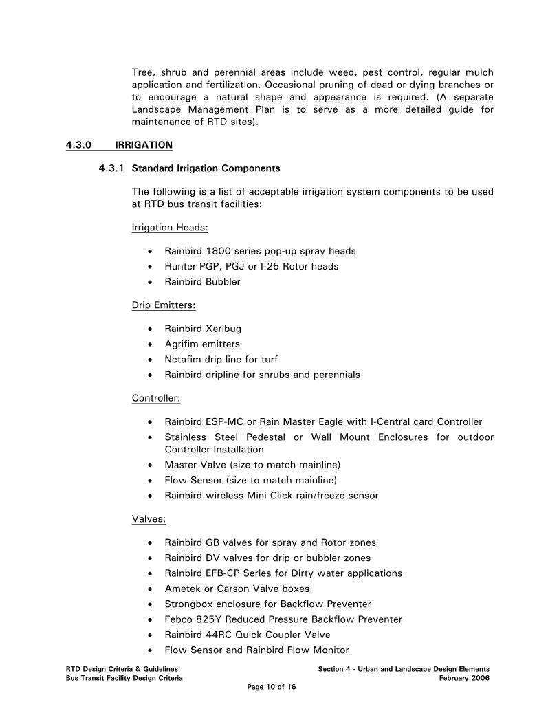
Tree, shrub and perennial areas include weed, pest control, regular mulch application and fertilization. Occasional pruning of dead or dying branches or to encourage a natural shape and appearance is required. (A separate Landscape Management Plan is to serve as a more detailed guide for maintenance of RTD sites).
4.3.0 IRRIGATION
4.3.1 Standard Irrigation Components
The following is a list of acceptable irrigation system components to be used at RTD bus transit facilities:
Irrigation Heads:
• Rainbird 1800 series pop-up spray heads
• Hunter PGP, PGJ or I-25 Rotor heads
• Rainbird Bubbler
Drip Emitters:
• Rainbird Xeribug
• Agrifim emitters
• Netafim drip line for turf
• Rainbird dripline for shrubs and perennials
Controller:
• Rainbird ESP-MC or Rain Master Eagle with I-Central card Controller
• Stainless Steel Pedestal or Wall Mount Enclosures for outdoor Controller Installation
• Master Valve (size to match mainline)
• Flow Sensor (size to match mainline)
• Rainbird wireless Mini Click rain/freeze sensor
Valves:
• Rainbird GB valves for spray and Rotor zones
• Rainbird DV valves for drip or bubbler zones
• Rainbird EFB-CP Series for Dirty water applications
• Ametek or Carson Valve boxes
• Strongbox enclosure for Backflow Preventer
• Febco 825Y Reduced Pressure Backflow Preventer
• Rainbird 44RC Quick Coupler Valve
• Flow Sensor and Rainbird Flow Monitor
RTD Design Criteria & Guidelines Section 4 - Urban and Landscape Design Elements Bus Transit Facility Design Criteria February 2006
Page 10 of 16
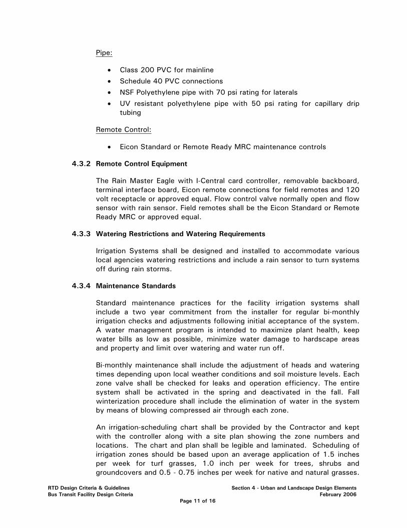
Pipe:
• Class 200 PVC for mainline
• Schedule 40 PVC connections
• NSF Polyethylene pipe with 70 psi rating for laterals
• UV resistant polyethylene pipe with 50 psi rating for capillary drip tubing
Remote Control:
• Eicon Standard or Remote Ready MRC maintenance controls
4.3.2 Remote Control Equipment
The Rain Master Eagle with I-Central card controller, removable backboard, terminal interface board, Eicon remote connections for field remotes and 120 volt receptacle or approved equal. Flow control valve normally open and flow sensor with rain sensor. Field remotes shall be the Eicon Standard or Remote Ready MRC or approved equal.
4.3.3 Watering Restrictions and Watering Requirements
Irrigation Systems shall be designed and installed to accommodate various local agencies watering restrictions and include a rain sensor to turn systems off during rain storms.
4.3.4 Maintenance Standards
Standard maintenance practices for the facility irrigation systems shall include a two year commitment from the installer for regular bi-monthly irrigation checks and adjustments following initial acceptance of the system. A water management program is intended to maximize plant health, keep water bills as low as possible, minimize water damage to hardscape areas and property and limit over watering and water run off.
Bi-monthly maintenance shall include the adjustment of heads and watering times depending upon local weather conditions and soil moisture levels. Each zone valve shall be checked for leaks and operation efficiency. The entire system shall be activated in the spring and deactivated in the fall. Fall winterization procedure shall include the elimination of water in the system by means of blowing compressed air through each zone.
An irrigation-scheduling chart shall be provided by the Contractor and kept with the controller along with a site plan showing the zone numbers and locations. The chart and plan shall be legible and laminated. Scheduling of irrigation zones should be based upon an average application of 1.5 inches per week for turf grasses, 1.0 inch per week for trees, shrubs and groundcovers and 0.5 - 0.75 inches per week for native and natural grasses.
RTD Design Criteria & Guidelines Section 4 - Urban and Landscape Design Elements Bus Transit Facility Design Criteria February 2006
Page 11 of 16
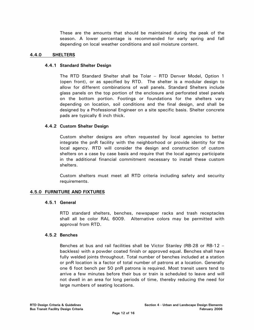
These are the amounts that should be maintained during the peak of the season. A lower percentage is recommended for early spring and fall depending on local weather conditions and soil moisture content.
4.4.0 SHELTERS
4.4.1 Standard Shelter Design
The RTD Standard Shelter shall be Tolar – RTD Denver Model, Option 1 (open front), or as specified by RTD. The shelter is a modular design to allow for different combinations of wall panels. Standard Shelters include glass panels on the top portion of the enclosure and perforated steel panels on the bottom portion. Footings or foundations for the shelters vary depending on location, soil conditions and the final design, and shall be designed by a Professional Engineer on a site specific basis. Shelter concrete pads are typically 6 inch thick.
4.4.2 Custom Shelter Design
Custom shelter designs are often requested by local agencies to better integrate the pnR facility with the neighborhood or provide identity for the local agency. RTD will consider the design and construction of custom shelters on a case by case basis and require that the local agency participate in the additional financial commitment necessary to install these custom shelters.
Custom shelters must meet all RTD criteria including safety and security requirements.
4.5.0 FURNITURE AND FIXTURES
4.5.1 General
RTD standard shelters, benches, newspaper racks and trash receptacles shall all be color RAL 6009. Alternative colors may be permitted with approval from RTD.
4.5.2 Benches
Benches at bus and rail facilities shall be Victor Stanley (RB-28 or RB-12 – backless) with a powder coated finish or approved equal. Benches shall have fully welded joints throughout. Total number of benches included at a station or pnR location is a factor of total number of patrons at a location. Generally one 6 foot bench per 50 pnR patrons is required. Most transit users tend to arrive a few minutes before their bus or train is scheduled to leave and will not dwell in an area for long periods of time, thereby reducing the need for large numbers of seating locations.
RTD Design Criteria & Guidelines Section 4 - Urban and Landscape Design Elements Bus Transit Facility Design Criteria February 2006
Page 12 of 16
All benches shall include anti-sleep rails that prevent a person from lying down on the bench.
4.5.3 Trash Receptacles
Trash receptacles are an inexpensive way to control litter at the pnR and station facilities. The trash receptacle shall be Victor Stanley (SD-42) with a powder coated finish, dome lid and latch door, or approved equal. Trash receptacles shall have fully welded joints throughout.
The number of trash receptacles shall be no less than two and no more than fifteen. The final amount will depend upon overall site design and configuration of newspaper, ticket and vending machine and waiting areas. No trash receptacles will be located within designated parking areas.
The location of trash receptacles shall meet the security requirements in subsection 12.15 of this Manual, which require they shall not be placed within 250 feet of a station, station area or patron gathering area for outside locations. Explosion resistant receptacles may be placed within 250 feet of a station, station area or patron gathering area. The Design Engineer shall coordinate with RTD for specifications for explosion resistant receptacles.
4.5.4 Public Telephones
At least one public telephone shall be provided at each bus transit facility, pnR or station location for convenience and safety. Total number of phones at each location will depend on number of patrons at each location. A minimum of one phone, plus one additional phone per 200 cars shall be installed. Location of public telephones shall be in close proximity to the designated parking areas and bus plaza areas. Public telephones are generally located in designated public information space that may include ticket vending machines, newspaper racks, system maps and information kiosks.
4.5.5 Newspaper Racks
Newspaper rack systems shall be provided for vendor use at each bus transit facility. These are installed to limit the number, types and colors of individual paper vending machines located at any one facility, and shall provide a neat and orderly appearance. The rack systems can be installed in groups of 6 or more to accommodate the number of vendors interested in providing a service. The color chosen for each location depends on the overall site design and location of the racks.
The location of newspaper rack systems shall meet the security requirements in subsection 12.15 of this Manual, which require that they shall not be placed within 250 feet of a station, station area or patron gathering area for outside locations.
RTD Design Criteria & Guidelines Section 4 - Urban and Landscape Design Elements Bus Transit Facility Design Criteria February 2006
Page 13 of 16
4.5.6 Food Vending Machines
Generally food vending machines are not included at RTD facilities. In situations where they are included, a special area shall be established with the proper electrical service, trash receptacles, access and cover.
4.5.7 Bike Lockers and Racks
See Section 5.
4.6.0 HARDSCAPE
4.6.1 Design Objective
The design objective of hardscape features at bus transit facilities shall be to develop elements for each location (some may be unique to the area) that provide a functional, aesthetically pleasing and maintainable site. Each element within the hardscape portion of the design shall be constructed of durable materials.
4.6.2 Access to Pedestrian Areas
Access to pedestrian plazas shall meet the requirements of ADA criteria (ADAAG), ANSI 117.1 or more restrictive requirements as determined by local, state or federal laws or codes.
RTD Design Criteria & Guidelines Section 4 - Urban and Landscape Design Elements Bus Transit Facility Design Criteria February 2006
Page 14 of 16
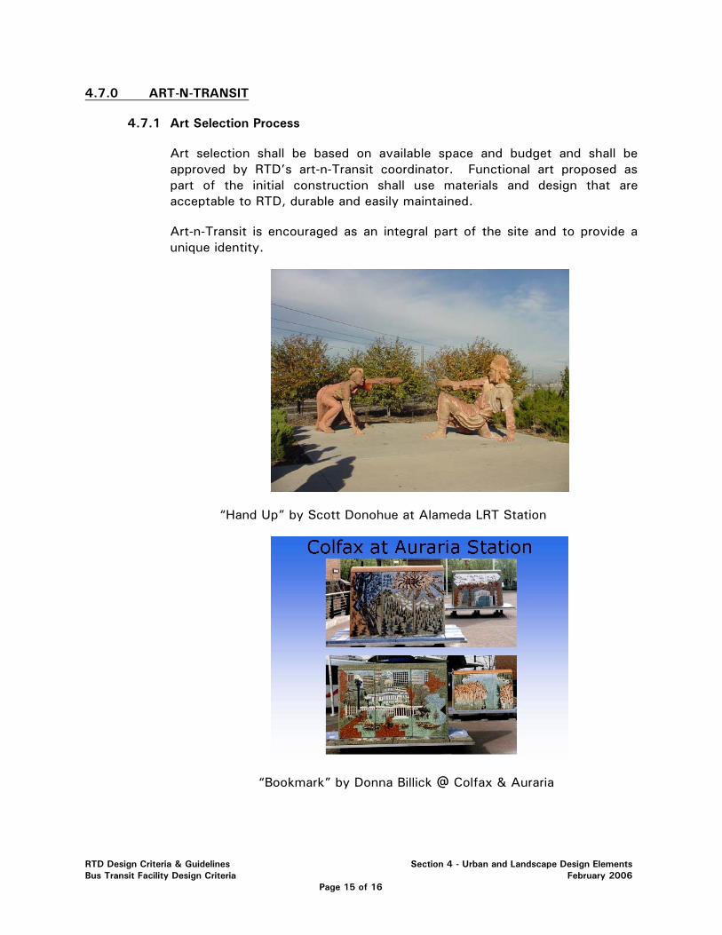
4.7.0 ART-N-TRANSIT
4.7.1 Art Selection Process
Art selection shall be based on available space and budget and shall be approved by RTD’s art-n-Transit coordinator. Functional art proposed as part of the initial construction shall use materials and design that are acceptable to RTD, durable and easily maintained.
Art-n-Transit is encouraged as an integral part of the site and to provide a unique identity.
“Hand Up” by Scott Donohue at Alameda LRT Station
“Bookmark” by Donna Billick @ Colfax & Auraria
RTD Design Criteria & Guidelines Section 4 - Urban and Landscape Design Elements Bus Transit Facility Design Criteria February 2006
Page 15 of 16
Art-n-Transit is a safety certifiable item under RTD’s Safety Certification Program (refer to Section 12). As such, art-n-transit design and placement shall be approved by RTD’s Executive Safety and Security Committee.
RTD Design Criteria & Guidelines Section 4 - Urban and Landscape Design Elements Bus Transit Facility Design Criteria February 2006
Page 16 of 16
SECTION 5 – BICYCLE FACILITIES
5.1.0 GENERAL....................................................................................................... 2 5.2.0 BICYCLE PARKING.......................................................................................... 2
5.2.1 Bike Racks ........................................................................................... 2 5.2.2 Bike Lockers......................................................................................... 2 5.2.3 Bike Corrals and Bikestations.................................................................. 3 5.2.4 Selecting Type and Quantity of Bike Parking............................................. 3
5.3.0 BIKEWAYS .................................................................................................... 4
5.3.1 Bikeway Connections ............................................................................ 4 5.3.2 Bicycle/Pedestrian Bridges...................................................................... 5 5.3.3 Bikeway Signage................................................................................... 5
RTD Design Guidelines & Criteria Section 5 - Bicycle Facilities Bus Transit Facility Design Criteria February 2006
Page 1 of 5
SECTION 5 – BICYCLE FACILITIES
5.1.0 GENERAL
This Design Criteria establishes the minimum standards to be used in the design of RTD bus transit facilities. This section is intended to direct the Design Engineer in the design of bicycle facilities at all RTD bus transit facilities.
All bike lanes, including those in public roads, should be designed in compliance with AASHTO and MUTCD requirements.
5.2.0 BICYCLE PARKING
Bicycle parking shall be provided based upon the guidelines presented below for initial construction, but consideration should be given to potential future expansions or reductions of the bike facilities in case demand warrants.
5.2.1 Bike Racks
Bicycle racks shall be placed near bus loading areas. The preferred type of bicycle racks to be used is “inverted-U” or “hoop” racks, as shown in RTD Standard Drawings. These racks are efficient for RTD use because they can be installed individually or in rows, as appropriate for different sites.
Bike racks shall be located as close to passenger loading areas as possible without interfering with passenger or vehicle movement. Bike parking is less likely to be used if it is not conveniently located. Additionally, racks that are not situated in a visible location are more prone to theft. When bike racks are not located in close proximity to passenger loading areas, they should be placed in a well lit location.
5.2.2 Bike Lockers
Bike lockers shall be placed off the main plaza and bus loading area, while still being conveniently located. Like bike racks, bike lockers should be located close enough to passenger loading areas to facilitate use. Ideally this location would be no further than the closest non-ADA parking space, as well as be a well lit location, near moderate to high patron activity zones in order to increase the perception of a safe locker area and increase the sense of security of the user and their equipment. However the location of bike lockers (and other publicly accessible receptacles) shall meet the security requirements in subsection 12.15 of this Manual, which require they shall not be placed within 250 feet of a station, station area or patron gathering area for outside locations. Bike lockers may be placed within 250 feet of a station, station area or patron gathering area with written approval from RTD.
The preferred type of bike lockers for RTD facilities is a fiber-reinforced polymer (FRP) composite enclosure with an open base. The preferred
RTD Design Guidelines & Criteria Section 5 - Bicycle Facilities Bus Transit Facility Design Criteria February 2006
Page 2 of 5
configuration for the lockers is a single rectangular unit that contains two triangular bays, each accessed from one end of the rectangular box. See RTD Standard Drawings for sample bike locker installation.
A minimum of 6 feet around the perimeter of bike lockers shall be maintained for user access and for snow removal equipment. If the locker cannot be secured to a concrete pad, a fiberglass composite locker floor shall be specified.
5.2.3 Bike Corrals and Bikestations
At sites with high bike traffic, with direction from RTD, a bike corral or bikestation shall be provided to accommodate the large number of bikes in a more attractive manner than expansive groups of racks and lockers.
5.2.3.1 Bike Corrals
Bike Corrals are sheltered and secured enclosures that can accommodate a large number of bikes efficiently. Riders can secure their bikes with individual locks, for added security, within the corral, which is designed to include a self-controlled access equipped with a smart-card or card-key locking mechanism. Bike corrals can be built to any specification, but generally take the form of an unused storage room or a fenced enclosure.
The size, location and design of any proposed bike corral will be site specific and shall be determined in conjunction with the RTD Planning and Development Department.
5.2.3.2 Bikestations
Bikestations are bike corrals that are staffed by parking attendants and offer other services and amenities. For example, a bikestation could provide transit passengers access to bike parking as well as bike repairs, bike rentals, bike accessories, transit pass sales, restrooms, changing stalls and a snack bar or café.
The size, location and design of any proposed bikestation will be site specific and shall be determined in conjunction with the RTD Planning and Development Department.
5.2.4 Selecting Type and Quantity of Bike Parking
There is no commonly accepted equation or model to establish the quantity or type of bike parking demand at bus transit facilities. Some factors that contribute to the demand are the level of transit service, surrounding land use, population demographics and proximity to bikeway facilities. General trends indicate that higher density areas have increased bicycle use. Similarly, younger populations (especially student populations) and lower
RTD Design Guidelines & Criteria Section 5 - Bicycle Facilities Bus Transit Facility Design Criteria February 2006
Page 3 of 5
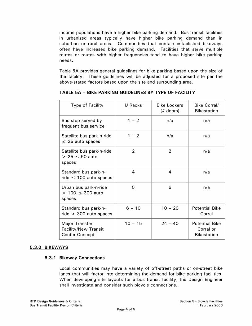
income populations have a higher bike parking demand. Bus transit facilities in urbanized areas typically have higher bike parking demand than in suburban or rural areas. Communities that contain established bikeways often have increased bike parking demand. Facilities that serve multiple routes or routes with higher frequencies tend to have higher bike parking needs.
Table 5A provides general guidelines for bike parking based upon the size of the facility. These guidelines will be adjusted for a proposed site per the above-stated factors based upon the site and surrounding area.
TABLE 5A – BIKE PARKING GUIDELINES BY TYPE OF FACILITY
Type of Facility U Racks Bike Lockers (# doors)
Bike Corral/ Bikestation
Bus stop served by frequent bus service
1 – 2 n/a n/a
Satellite bus park-n-ride ≤ 25 auto spaces
1 – 2 n/a n/a
Satellite bus park-n-ride > 25 ≤ 50 auto spaces
2 2 n/a
Standard bus park-n-ride ≤ 100 auto spaces
4 4 n/a
Urban bus park-n-ride > 100 ≤ 300 auto spaces
5 6 n/a
Standard bus park-n-ride > 300 auto spaces
6 – 10 10 – 20 Potential Bike Corral
Major Transfer Facility/New Transit Center Concept
10 – 15 24 – 40 Potential Bike Corral or
Bikestation
5.3.0 BIKEWAYS
5.3.1 Bikeway Connections
Local communities may have a variety of off-street paths or on-street bike lanes that will factor into determining the demand for bike parking facilities. When developing site layouts for a bus transit facility, the Design Engineer shall investigate and consider such bicycle connections.
RTD Design Guidelines & Criteria Section 5 - Bicycle Facilities Bus Transit Facility Design Criteria February 2006
Page 4 of 5
RTD encourages joint collaborations with local jurisdictions and agencies to provide better bicycle access to transit facilities where regional bike routes intersect or come within near proximity to RTD bus transit facilities.
When designing bikeways on RTD sites, where bike routes come onto RTD property, jurisdictional standards for size and surface material shall be met or exceeded (budget permitting). For example, if the current standard for a municipality is to surface regional bike trails with crusher fines, that would also be the minimum allowable surface within RTD’s site. If the project budget can accommodate upgrading the bike path to asphalt or concrete, it would be recommended to do so.
Geometric standards for bikeway design shall be based upon local jurisdictional requirements or the AASHTO “Guide for the Development of Bicycle Facilities” manual if the local jurisdiction has no standards that address bikeways.
5.3.2 Bicycle/Pedestrian Bridges
Bridges may be necessary at some public bus facilities if major barriers to site access exist (i.e.: highways, RR, rivers). Refer to Section 6 of this Manual for further information on the design of such structures.
RTD will determine the practicality for bicycle/pedestrian bridges on a case-by-case basis, depending upon the projected pedestrian traffic, the geography of the site and the anticipated project cost.
5.3.3 Bikeway Signage
Where regional paths are not directly adjacent to RTD property, there should be clear signage directing bike traffic to and from the transit facility. Coordination with the local jurisdiction will be necessary to place signs along the bike path that direct riders along the most convenient route to reach the bus facility. The signs shall meet local standards, RTD’s signage requirements as stated in Section 8 of this Manual and be in conformance with the MUTCD.
RTD Design Guidelines & Criteria Section 5 - Bicycle Facilities Bus Transit Facility Design Criteria February 2006
Page 5 of 5
SECTION 6 – STRUCTURAL DESIGN 6.1.0 STRUCTURAL DESIGN CODES, MANUALS & SPECIFICATIONS ......................... 3
6.1.1 Building Codes................................................................................ 3 6.2.0 EARTH RETAINING STRUCTURES .................................................................. 3
6.2.1 Geometry....................................................................................... 3 6.2.2 Type ............................................................................................. 3 6.2.3 Design Requirements....................................................................... 3 6.2.4 Characteristics................................................................................ 4
6.3.0 CONCRETE .................................................................................................. 5 6.4.0 STRUCTURAL STEEL .................................................................................... 5 6.5.0 PRESTRESSING STEEL .................................................................................. 5 6.6.0 POST-TENSIONING STEEL SYSTEMS.............................................................. 5 6.7.0 REINFORCING STEEL .................................................................................... 5 6.8.0 TIMBER ....................................................................................................... 5 6.9.0 TEMPORARY STRUCTURES........................................................................... 5 6.10.0 SLABS ........................................................................................................ 5 6.11.0 TUNNELS AND BRIDGES ............................................................................... 6 6.12.0 PEDESTRIAN BRIDGES.................................................................................. 6 6.13.0 PARKING STRUCTURES ................................................................................ 6
6.13.1 Objectives..................................................................................... 6 6.13.2 Modal Hierarchy ............................................................................ 7 6.13.3 Parking Structure Context ............................................................... 8 6.13.4 Design Goals ................................................................................. 8 6.13.5 Performance Standards................................................................... 9 6.13.6 Functional Design ........................................................................ 10 6.13.7 Access Design............................................................................. 11 6.13.8 Security...................................................................................... 11 6.13.9 Lighting ...................................................................................... 11 6.13.10 Signage and Graphics .................................................................... 11 6.13.11 Structure ..................................................................................... 12 6.13.12 Architecture ................................................................................. 12
RTD Design Guidelines & Criteria Section 6 – Structural Design Bus Transit Facility Design Criteria February 2006
Page 1 of 13
6.13.13 Fire Protection .............................................................................. 12 6.13.14 Maintenance Objectives................................................................. 12 6.13.15 ADAAG ....................................................................................... 13
6.14.0 GEOTECHNICAL ANALYSIS......................................................................... 13 6.15.0 LOADS AND FORCES.................................................................................. 13
RTD Design Guidelines & Criteria Section 6 – Structural Design Bus Transit Facility Design Criteria February 2006
Page 2 of 13
SECTION 6 – STRUCTURAL DESIGN CRITERIA
6.1.0 STRUCTURAL DESIGN CODES, MANUALS & SPECIFICATIONS
Load Factor Design, Allowable Stress Design and Load Resistance Factor Design (LRFD) are acceptable design concepts upon written approval from RTD. The designer shall coordinate the specific design methodology with RTD’s structural engineer prior to commencing with preliminary design calculations and layout. All structural designs shall be signed and sealed by a Professional Engineer registered in the State of Colorado. All revisions shall be reviewed, and signed and sealed by a Professional Engineer registered in the State of Colorado. Unless otherwise specified herein, the following codes, manuals or specifications as appropriate or codes, manuals or specifications of other local jurisdictions shall guide the structural design.
6.1.1 Building Codes
The most recent edition of: Uniform Building Code, International Building Code, City and County of Denver and State of Colorado, Structural Specialty Code and Fire and Life Safety Code, and local jurisdictional codes, as required.
6.2.0 EARTH RETAINING STRUCTURES
For earth retaining structures located either on caissons or other foundations, the AASHTO Specifications for Retaining Walls and CDOT design specifications shall be followed.
6.2.1 Geometry
Retaining wall layout shall address slope maintenance above and below the wall. Provide returns into the retained fill or cut at retaining wall ends where possible. Any residual wall batter should be into the fill. Design and construction shall consider surface and subsurface drainage. A drainage system shall be provided to intercept or prevent surface water from entering behind walls. A fence or pedestrian railing with a minimum height of 42 inches above a standing surface shall be provided at the top of walls 30 inches or higher.
6.2.2 Type
Metal walls, including bin walls and sheet pile walls, and recycled material walls will not be permitted for permanent retaining walls. Timber walls will not be permitted for permanent retaining walls unless prior approval by RTD. Wall types, proposed for use, shall have successfully been used in similar geotechnical locations and environmental conditions.
6.2.3 Design Requirements
Retaining walls shall be designed in accordance with the applicable standards and references outlined in this Design Criteria. The design of MSE and modular walls near or in bodies of water shall account for soft saturated soils and scour. All project walls near irrigation lines for landscaping shall account for the additional hydrostatic load due to a waterline break. The use of free draining backfill material and/or leak detection devices to reduce
RTD Design Guidelines & Criteria Section 6 – Structural Design Bus Transit Facility Design Criteria February 2006
Page 3 of 13
hydrostatic loads on retaining walls shall be included. All wall systems shall be designed to have a minimum service life of 50 years.
6.2.4 Characteristics
Mechanically Stabilized Earth (MSE) Walls - Wall panels shall be constructed of reinforced concrete. Provide corrosion protection for prestressing or posttensioning steel.
Panel joints - shall accommodate differential settlement. Use section 206 of the CDOT – Standard Specifications for Road and Bridge Construction for backfill requirements.
Reinforcing - Cover to reinforcing steel shall be a minimum of 2 inches with forms and 3 inches without forms. All reinforcing, mild or prestressed shall be galvanized or epoxy coated in splash zones of adjacent roadways.
Modular Walls - Modular wall height shall not exceed 15 feet. A mechanical connection to the wall facing for soil reinforcement shall be provided; friction connections relying on gravity alone will not be acceptable.
Cast-in-Place Walls - Cast in place walls shall be designed and constructed in accordance with the current AASHTO Standard Specifications for Highway Bridges, CDOT design specifications and all interims through the present. Construction joint spacing shall accommodate differential settlement.
Anchored Walls - Anchored wall design and construction shall use FHWA RD-82-046, FHWA RD-82-047 and FHWA-IF-99-015 as guidelines. Anchors shall be encapsulated with plastic sheathing. Proof load tests for anchors shall be provided in accordance with the above FHWA guidelines. Shotcrete shall meet the aesthetic requirements set by RTD.
Soil Nail Walls - Soil nail walls may be used when top-down construction is warranted. Soil nail walls shall not be used if ground water seepage will be a problem. Design and construction shall use FHWA-RD-89-93, FHWA-SA-93-086 and FHWA-SA-96-069 as guidelines. Load testing for nails shall be provided in accordance with the above FHWA guidelines. Shotcrete shall meet the aesthetic requirements, including final finish, as established by RTD.
Soil Reinforcement - Soil reinforcement for MSE and modular walls shall be galvanized, epoxy coated steel or geogrids meeting creep requirements of AASHTO Standard Specifications for Highway Bridges. Design shall account for any item projecting through the soil reinforcement. Avoid placing culverts and utilities perpendicular to soil reinforcement within the reinforced soil mass. Soil reinforcement shall be protected from corrosion of metal due to stray electrical currents. Requirements for stray current control shall follow the project standards as defined by RTD.
Structural Diaphragm Walls - Structural diaphragm walls may be used when top-down construction is warranted.
RTD Design Guidelines & Criteria Section 6 – Structural Design Bus Transit Facility Design Criteria February 2006
Page 4 of 13
6.3.0 CONCRETE
Structures designed to carry highway loadings shall be designed to current AASHTO and CDOT specification including the most current interims.
The use of lightweight concrete is not allowed for use in structural members.
Minimum allowable concrete strengths shall meet the requirements of Section 601 of CDOT - Standard Specifications for Road and Bridge Construction.
6.4.0 STRUCTURAL STEEL
Structures designed to carry or support highway loadings shall be designed to current AASHTO and CDOT Specifications including the most current interims.
6.5.0 PRESTRESSING STEEL
The maximum diameter for prestressing strands shall be 0.6 inches for a 2 inch minimum spacing and 0.5 inches for a 1-3/4 inch minimum spacing.
6.6.0 POST-TENSIONING STEEL SYSTEMS
Provide corrosion protection for the strands consisting of grout filled galvanized or nonmetallic ducts. Grout shall meet the requirements of Section 618 of CDOT Standard Specifications for Road and Bridge Construction. Prestressing systems shall be from PTI Certified plants.
6.7.0 REINFORCING STEEL
The use of epoxy coated reinforcing steel for all bridges, walls, tunnels and box culverts shall adhere to the requirements of Table 1, Subsection No. 8.1 of the CDOT Bridge Design Manual. The design category for anticipated level of de-icing salt application shall be “Low.” Specific reinforcing steel for bridges, not covered herein, shall conform to the requirements of CDOT Standard Specifications for Road and Bridge Construction.
Abutments, pier columns, and superstructures exposed to splash from adjacent roadway shall use epoxy coated reinforcing steel conforming to the requirements of CDOT.
6.8.0 TIMBER
For timber structures other than structures subjected to highway loading, the National Design Specification for Wood Construction, by the National Forest Products Association shall be followed. Timber structures with over 20 feet of span length shall not be allowed for permanent structures.
6.9.0 TEMPORARY STRUCTURES
All materials for temporary structures both above and below ground shall be removed unless given specific permission from RTD to leave in place.
6.10.0 SLABS
Structural slabs shall be designed to handle all loading that may be potentially placed upon them. For slabs in areas handling pedestrian loading and snow loads, design shall include HS15 truck loading at a minimum. Reinforcing in areas exposed to weather and de-icing chemicals shall have galvanized or epoxy coated reinforcement. For slabs subjected to heavier loads, design shall include HS20 loading at a minimum.
RTD Design Guidelines & Criteria Section 6 – Structural Design Bus Transit Facility Design Criteria February 2006
Page 5 of 13
6.11.0 PEDESTRIAN TUNNELS
Pedestrian tunnels shall provide a minimum width of 20 feet for pedestrian movement. Pedestrian tunnels shall be well lit and provided with security cameras in accordance with Section 12 of this Manual.
See RTD Light Rail Design Criteria.
6.12.0 PEDESTRIAN BRIDGES
Pedestrian bridges shall be designed in accordance with the requirements of AASHTO Standard Specifications for Highways and Bridges, AASHTO Guide Specification for Pedestrian Bridge, and CDOT Standard Specifications for Road and Bridge Construction.
The Design Engineer shall coordinate with RTD for the design of covers on pedestrian walkways over LRT tracks or roadways.
Pedestrian bridges shall provide a minimum width of 12 feet for pedestrian movement. Pedestrian bridges shall be well lit and provided with security cameras in accordance with Section 12 of this Manual.
6.13.0 PARKING STRUCTURES
6.13.1 Objectives
The design criteria for this section were derived from an evaluation and review of design manuals, agency criteria and existing parking structures that service transit agencies, including RTD.
The objective of this section shall provide the basis for design decisions. The objectives shall be used in the design of new and renovated facilities.
In addition to safety and functionality, the design objectives shall consider these four factors:
• Budget
• Architecture
• Intermodal Transfer
• Community Integration
Budget
The established construction budget shall take precedence over all other factors other than safety and functionality.
Architecture
• Create a civic architecture that is permanent, functional and pleasant. The structure should contribute to the RTD context – one that is not entirely derivative of the transit system, but complimentary of the neighborhoods and community within which it is located and within budget constraints. The structure should maintain an overall system or corridor identity.
RTD Design Guidelines & Criteria Section 6 – Structural Design Bus Transit Facility Design Criteria February 2006
Page 6 of 13
• All designs must conform to current editions of all applicable codes (e.g., UBC, IBC, ANSI, ADAAG).
• Make transit safe, secure, friendly and accessible to all, including the disabled.
• Design systems that use sustainable, consistent and maintainable materials that minimize life cycle costs.
• Provide an architectural and urban design framework that defines and encourages TOD opportunities.
Intermodal Transfer
• Provide a safe, efficient, and convenient parking structure configuration for intermodal transfer.
• Provide clear and understandable directional signage.
• Develop operational efficiencies that simplify modal transfers and commuter accessibility.
• Provide the best service possible at a reasonable cost.
Community Integration
• Protect, maintain and enhance existing community values.
• Support TOD that fosters neighborhood friendly and desirable facilities.
• Support transit-related uses that are proximate to the transit facilities.
• Initiate and coordinate programs with the community that limit local traffic impacts and minimize disruption during and after the implementation phase.
• Utilize local jurisdictional processes and agencies throughout project design and implementation.
6.13.2 Modal Hierarchy
Parking structures shall be located to minimize the total passenger access time from all modes and, as applicable, enhance TOD potential.
Access modes for and around parking structures shall be located relative to rail platforms and bus bays in the following hierarchy:
• Light Rail Transit/Commuter Rail
• Fixed route feeder bus
• Other fixed route buses
• Taxi and paratransit (private or flexible route bus) drop off
• Auto drop off
• Bicycle parking
RTD Design Guidelines & Criteria Section 6 – Structural Design Bus Transit Facility Design Criteria February 2006
Page 7 of 13
• Auto parking
• Motorcycle parking
• Offsite Pedestrian
6.13.3 Parking Structure Context
The “context” is the state of development that surrounds a perspective parking structure site. It can be residential, commercial, industrial, agricultural, suburban, urban, or rural. The character, quality, land use and future of the context shall direct the site planning and design of parking structures.
While all parking structures are to be compatible with existing RTD facilities each parking structure will also be a derivative of the neighborhoods and communities of which it is a part; therefore, parking structures should:
• Contribute to the character and quality of their context.
• Help establish new development patterns where appropriate
• Reinforce and guide desired and established development patterns.
• Recognize development patterns that can be complemented.
• Establish development patterns in rural areas by providing focus and structure for future development.
6.13.4 Design Goals
Design of parking structures and site planning shall include:
Vehicle and Passenger Flow Accommodation:
• Minimize crowding, travel obstructions, conflicts, disorientation, level changes and physical barriers.
• Maximize safety, reliability and the ability to accommodate emergencies.
Passenger Environmental Accommodation:
• Provide adequate lighting, personal comfort, aesthetic quality, weather protection and security.
Design Flexibility
• Allow for future operating changes with minimal reconstruction.
• Coordinate with RTD during concept design phase on needs for future vertical or horizontal expansion of the structure.
Community Enhancement:
• Minimize impacts on local vehicular and pedestrian traffic.
• Promote desired growth.
• Neighborhood context.
RTD Design Guidelines & Criteria Section 6 – Structural Design Bus Transit Facility Design Criteria February 2006
Page 8 of 13
6.13.5 Performance Standards
• Durability – Durable and cost-effective materials shall be used that have consistent wear, strength and weathering qualities. Materials shall be capable of good appearance throughout a 50 year useful life.
• Low Maintenance – Life cycle maintenance costs shall be considered in the evaluation of all materials and finishes.
• Quality of Appearance – Materials shall be appealing and harmonious in appearance and texture. They shall reinforce system continuity while relating to local context.
• Drainage – Positive drainage shall be provided for all surfaces within the structure. Grades shall not be less than 0.5% in order to eliminate construction related sump (bird bath, pond) conditions. Ponding water within the parking structure is not acceptable.
• Cleaning – Materials that do not soil nor stain easily shall be used and shall have surfaces that are easily cleaned in a single operation. All porous finishes subject to public contact shall be treated or finished in a manner that allows easy recovery from “casual vandalism.”
• Repair of Replacement – Inventory and maintenance costs shall be minimized. Materials shall be standardized as much as possible for easy repair or replacement without undue cost or operational disruption. For example, hose bibs, electrical outlets, lighting fixtures and lamps, glass or plastic lights, information panels, signs, shelter material, etc., shall be standardized using commonly available sizes and finishes for easy inventory stocking and installation.
• Nonslip – Entrances, stairways, and areas around equipment shall have high nonslip properties. Floor finishes shall be nonslip even when wet. This is particularly important at stairs, elevators, and other areas near station entrances as well as platform areas.
• Corrosion Resistance – Because of moisture and the electrical currents associated with transit operation, special consideration must be given to prevent corrosion. Non-corrosive metals shall be utilized. Structures near the LRT guideway shall be grounded. Stairs shall either be precast or cast in place concrete.
• Compatibility – Selected materials shall be compatible with the Denver area climate.
• Availability – Selection of materials shall permit competitive bidding and emphasize regional products and processes over those not available locally.
• Graffiti resistant products shall be used to protect surfaces susceptible to graffiti. The designer shall coordinate with RTD on which surfaces require protection.
RTD Design Guidelines & Criteria Section 6 – Structural Design Bus Transit Facility Design Criteria February 2006
Page 9 of 13
• Pavement markings within parking structures shall include glass beads for reflectivity. Glass beads shall meet the requirements of section 713.08 of the CDOT Standard Specifications.
6.13.6 Functional Design
Parking facility design shall consider the following:
• Access
• User type
• Pedestrian needs
• Wayfinding Signage
• Floor-to-floor height
• Dimensions of site
• Parking geometrics
• Peak-hour volumes
• Flow capacity
• Lighting
• Fire Protection
Level of Service
Vehicular Level of Service (LOS) shall be considered for parking structure entry/exits, geometrics, flow capacity, travel distance, turning radii, and floor slopes. For typical parking structures the LOS can range from A to D with D being the lowest.
The level of service at the access to public ROW shall not be less than C. This may require extra drive/access lanes.
Circulation Systems
Circulation systems shall be oriented with drive aisles parallel to pedestrian flows along the shortest routes to station platforms or bus bays, whenever practical, in order to encourage pedestrians to walk along aisles where they can be easily seen by vehicle drivers.
Perpendicular aisles will be considered on a case-by-case basis with RTD approval. The need for pedestrian sidewalks and crosswalks shall be evaluated by the designer during conceptual planning.
Stall Widths and Parking Modules
In general, parking structures shall utilize 90 degree parking depending on site constraints and parking structure grid layout. For two-way drive aisles, with 90 degree parking, stalls shall be 8.5 feet by 18 feet with an aisle width of 24 feet. The parking module (i.e. two parking aisles and drive aisle) shall be 60 feet wide. One-way traffic with angled parking may be considered on a case-by-case basis, with RTD approval.
RTD Design Guidelines & Criteria Section 6 – Structural Design Bus Transit Facility Design Criteria February 2006
Page 10 of 13
6.13.7 Access Design
Entry/exit areas for parking structures are critical locations. Care must be taken to determine where entrances and exits will be placed with relation to access roadways, bus lanes, pedestrian movement, TOD and bicycle paths. Primary pedestrian paths through the parking structure shall not be located near entry/exits areas.
Entry/exit areas shall be designed for the parking peak and daily loads. Additionally, entry/exit lane lengths and widths shall be designed to accommodate future revenue control equipment. Depending on peak loads and total parking capacity, more than one access point shall be considered.
Kiss-n-rides (short term parking) shall be incorporated into the parking structure design. Kiss-n-rides located within the parking structures must not interfere with other vehicles trying to move through the facility. When RTD surface parking is located adjacent to a parking structure, kiss-n-rides shall be located within the surface lot.
6.13.8 Security
See Section 12 of this Manual for security requirements at parking structures.
6.13.9 Lighting
Lighting for parking structures shall meet the minimum requirements set forth in Section 9 of this Manual.
These standards recommend minimum illuminance criteria for the safe movement of vehicle traffic and pedestrians within a parking structure. They also recognize the need to deter criminal activity and meet energy constraints. The lighting must also be adequate for CCTV usage within the facility.
Lamp and fixture selections will be governed by RTD. Refer to Section 9 of this Manual for additional information.
Light poles used on the top tier of all facilities shall be hinged near the base to allow easy access to the fixtures and lamps.
6.13.10 Signage and Graphics
Signage provides directions, identification, and warnings, as well as other information to the users of the parking structure. Graphics are the means by which the information is presented on a sign. It is the intention of RTD that the signage in the parking facilities is plain, concise and simple.
Signage shall be in accordance with the requirements of the local jurisdiction, MUTCD, ADA and shall be clear, understandable and provide total coverage.
RTD Design Guidelines & Criteria Section 6 – Structural Design Bus Transit Facility Design Criteria February 2006
Page 11 of 13
6.13.11 Structure
Structural systems for parking structures shall be either precast prestressed concrete or cast in place post tensioned concrete and should consider cost, availability, quality, estimated life, function and appearance. The structural elements shall be consistent and replicated from one zone to the next, in order to simplify construction and minimize costs. Unique, aesthetically different and diverse structural elements within an individual structure are discouraged.
6.13.12 Architecture
The standard façade for parking structures shall be precast acid etched colored concrete panels. Maximum glass size for stair towers and elevators shall be 16 square feet (4’ x 4’).
6.13.13 Fire Protection
New parking structures and renovation projects shall be designed to incorporate efficient, cost-effective passive and automatic fire protection systems. These systems are effective in detecting, containing, and controlling and/or extinguishing a fire incident in the early stages. Fire protection engineers shall be involved in all aspects of the design in order to ensure an acceptable degree of protection of human life from fire and the products of combustion as well as to reduce the potential loss from fire (i.e., real and personal property, operations).
Planning for fire protection in and around a building involves an integrated systems approach that enables the designer to analyze all of the building's components as a total building fire safety system package. The analysis requires more than code compliance or meeting the minimum legal responsibilities for protecting a building. Therefore, it is necessary to creatively and efficiently integrate code requirements with other fire safety measures as well as other design strategies to achieve a balanced design that will provide the desired levels of safety, including and most importantly, coordination with the local fire authority.
Refer to Section 12 and the following for specific requirements:
• NFPA 88A, Standard for Parking Structures
• Uniform Fire Code
• Local jurisdiction fire and building codes
6.13.14 Maintenance Objectives
• Maximize ease of replacement
• Maximize ease of construction
• Maximize the use of available materials and finishes
• Maximize the use of durable materials and finishes
• Maximize the use of similar materials, finished and components.
RTD Design Guidelines & Criteria Section 6 – Structural Design Bus Transit Facility Design Criteria February 2006
Page 12 of 13
• Maximize the use of new improved materials and finishes
• Minimize the number of unique and different components
• Minimize the number of shapes
• Minimize life cycle costs
6.13.15 ADAAG
Parking structures shall be designed to conform to all regulations in accordance with ADAAG. This will include accessible paths, number of ADA parking stalls, etc.
6.14.0 GEOTECHNICAL ANALYSIS
The soils in the Denver metropolitan area vary. Soil and geologic data and reports for the preliminary design of structures shall be site specific. Preliminary recommendations shall be provided in the project structural reports prepared during the Preliminary Engineering phase. On Final Design, site-specific soil and geological data shall be obtained to develop the design parameters.
Commonly used foundations for bridges, retaining structures and buildings include: spread footings, driven precast concrete piles and drilled shafts. Foundations recommendations shall be made in a site-specific project geotechnical report. Foundations shall be designed according to AASHTO, CDOT Standards, or local requirements. River scour shall be included in geotechnical reports where appropriate.
6.15.0 LOADS AND FORCES
See RTD Light Rail Design Criteria.
RTD Design Guidelines & Criteria Section 6 – Structural Design Bus Transit Facility Design Criteria February 2006
Page 13 of 13
SECTION 7 – DRIVERS RELIEF STATION
7.1.0 GENERAL ..................................................................................................... 2 7.2.0 LOCATION.................................................................................................... 2 7.3.0 SIZE AND CONFIGURATION ........................................................................... 2
7.3.1 Prefabricated (Lavatory and Mechanical Room) ................................... 2 7.3.2 Small (Lavatory and Mechanical Room).............................................. 3 7.3.3 Medium (Lavatory, Mechanical and Security Rooms) ........................... 3 7.3.4 Large (Lavatory, Mechanical, Security and Maintenance Storage Rooms)3
7.4.0 MATERIALS AND EQUIPMENT........................................................................ 3
7.4.1 General.......................................................................................... 3 7.4.2 Lavatory ........................................................................................ 4 7.4.3 Mechanical Room............................................................................ 5 7.4.4 Security Room................................................................................ 5 7.4.5 Maintenance Storage Room.............................................................. 5
RTD Design Criteria & Guidelines Section 7 - Driver Relief Station Bus Transit Facility Design Criteria February 2006
Page 1 of 5
SECTION 7 – DRIVER RELIEF STATION
7.1.0 GENERAL
This Design Criteria establishes the minimum standards to be used in the design of RTD bus transit facilities. This section is intended to direct the Design Engineer in the design of structures used at bus transit facilities for various applications that are necessary for RTD employees to carry out their assignments. These structures are the Drivers Relief Station (DRS). The purpose of the DRS is to contain a toilet and sink, exclusively for District employees (primarily drivers). Depending on the site requirements, these structures may also include rooms for maintenance storage and site security equipment.
All DRS buildings shall be designed in accordance with ADA and ADAAG.
7.2.0 LOCATION
The DRS shall be located adjacent to bus loading areas. Specific locations will vary from site to site and the Design Engineer shall consider the location of utilities when selecting an appropriate location. The building design shall be in accordance with the following criteria:
convenient access for drivers, but placed beyond pedestrian traffic flow paths in the bus loading and plaza areas
all sides shall be accessible to maintenance personnel
all sides with access doors shall have a 6 foot (minimum) clearance for snow removal equipment
7.3.0 SIZE AND CONFIGURATION
There are four basic configuration options for the DRS, as described below. Please reference the RTD Standard Drawings for more details regarding each configuration. Based upon special needs or site conditions, the standard configurations may be customized for a specific location, but where possible, one of the four following options should be utilized. All four standard configurations are shown in the RTD Standard Drawings.
7.3.1 Prefabricated (Lavatory and Mechanical Room) – DRS I
The prefabricated option for the DRS shall contain all the basic components required in the lavatory and mechanical room. The restroom area should be approximately 5.5’ by 5.0’, and the attached mechanical room should be 2.0’ by 5.0’, resulting in a total building dimension of 7.5’ by 5.0’.
RTD Design Criteria & Guidelines Section 7 - Driver Relief Station Bus Transit Facility Design Criteria February 2006
Page 2 of 5
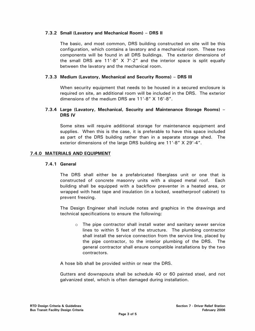
7.3.2 Small (Lavatory and Mechanical Room) – DRS II
The basic, and most common, DRS building constructed on site will be this configuration, which contains a lavatory and a mechanical room. These two components will be found in all DRS buildings. The exterior dimensions of the small DRS are 11’-8” X 7’-2” and the interior space is split equally between the lavatory and the mechanical room.
7.3.3 Medium (Lavatory, Mechanical and Security Rooms) – DRS III
When security equipment that needs to be housed in a secured enclosure is required on site, an additional room will be included in the DRS. The exterior dimensions of the medium DRS are 11’-8” X 16’-8”.
7.3.4 Large (Lavatory, Mechanical, Security and Maintenance Storage Rooms) – DRS IV
Some sites will require additional storage for maintenance equipment and supplies. When this is the case, it is preferable to have this space included as part of the DRS building rather than in a separate storage shed. The exterior dimensions of the large DRS building are 11’-8” X 29’-4”.
7.4.0 MATERIALS AND EQUIPMENT
7.4.1 General
The DRS shall either be a prefabricated fiberglass unit or one that is constructed of concrete masonry units with a sloped metal roof. Each building shall be equipped with a backflow preventer in a heated area, or wrapped with heat tape and insulation (in a locked, weatherproof cabinet) to prevent freezing.
The Design Engineer shall include notes and graphics in the drawings and technical specifications to ensure the following:
o The pipe contractor shall install water and sanitary sewer service lines to within 5 feet of the structure. The plumbing contractor shall install the service connection from the service line, placed by the pipe contractor, to the interior plumbing of the DRS. The general contractor shall ensure compatible installations by the two contractors.
A hose bib shall be provided within or near the DRS.
Gutters and downspouts shall be schedule 40 or 60 painted steel, and not galvanized steel, which is often damaged during installation.
RTD Design Criteria & Guidelines Section 7 - Driver Relief Station Bus Transit Facility Design Criteria February 2006
Page 3 of 5
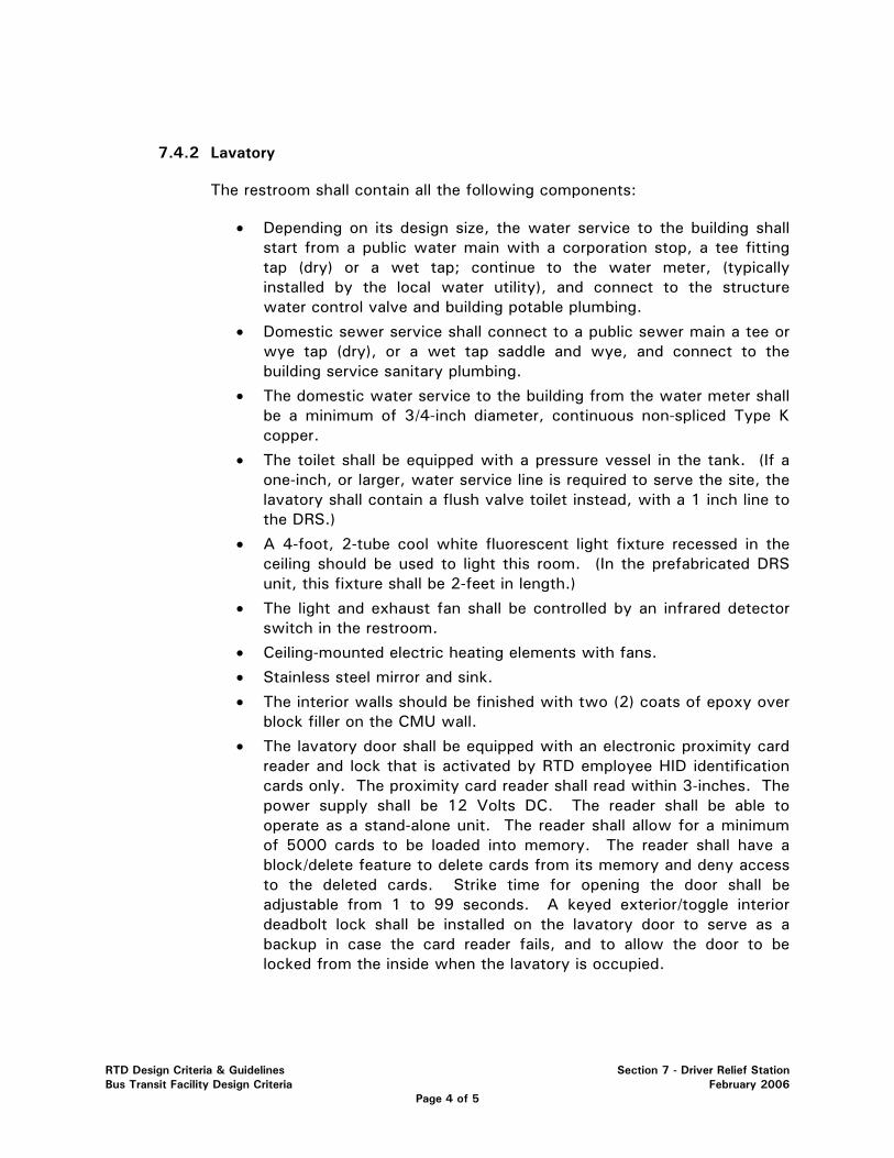
7.4.2 Lavatory
The restroom shall contain all the following components:
• Depending on its design size, the water service to the building shall start from a public water main with a corporation stop, a tee fitting tap (dry) or a wet tap; continue to the water meter, (typically installed by the local water utility), and connect to the structure water control valve and building potable plumbing.
• Domestic sewer service shall connect to a public sewer main a tee or wye tap (dry), or a wet tap saddle and wye, and connect to the building service sanitary plumbing.
• The domestic water service to the building from the water meter shall be a minimum of 3/4-inch diameter, continuous non-spliced Type K copper.
• The toilet shall be equipped with a pressure vessel in the tank. (If a one-inch, or larger, water service line is required to serve the site, the lavatory shall contain a flush valve toilet instead, with a 1 inch line to the DRS.)
• A 4-foot, 2-tube cool white fluorescent light fixture recessed in the ceiling should be used to light this room. (In the prefabricated DRS unit, this fixture shall be 2-feet in length.)
• The light and exhaust fan shall be controlled by an infrared detector switch in the restroom.
• Ceiling-mounted electric heating elements with fans.
• Stainless steel mirror and sink.
• The interior walls should be finished with two (2) coats of epoxy over block filler on the CMU wall.
• The lavatory door shall be equipped with an electronic proximity card reader and lock that is activated by RTD employee HID identification cards only. The proximity card reader shall read within 3-inches. The power supply shall be 12 Volts DC. The reader shall be able to operate as a stand-alone unit. The reader shall allow for a minimum of 5000 cards to be loaded into memory. The reader shall have a block/delete feature to delete cards from its memory and deny access to the deleted cards. Strike time for opening the door shall be adjustable from 1 to 99 seconds. A keyed exterior/toggle interior deadbolt lock shall be installed on the lavatory door to serve as a backup in case the card reader fails, and to allow the door to be locked from the inside when the lavatory is occupied.
RTD Design Criteria & Guidelines Section 7 - Driver Relief Station Bus Transit Facility Design Criteria February 2006
Page 4 of 5
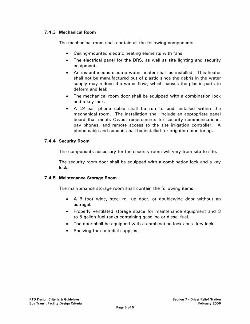
7.4.3 Mechanical Room
The mechanical room shall contain all the following components:
• Ceiling-mounted electric heating elements with fans.
• The electrical panel for the DRS, as well as site lighting and security equipment.
• An instantaneous electric water heater shall be installed. This heater shall not be manufactured out of plastic since the debris in the water supply may reduce the water flow, which causes the plastic parts to deform and leak.
• The mechanical room door shall be equipped with a combination lock and a key lock.
• A 24-pair phone cable shall be run to and installed within the mechanical room. The installation shall include an appropriate panel board that meets Qwest requirements for security communications, pay phones, and remote access to the site irrigation controller. A phone cable and conduit shall be installed for irrigation monitoring.
7.4.4 Security Room
The components necessary for the security room will vary from site to site.
The security room door shall be equipped with a combination lock and a key lock.
7.4.5 Maintenance Storage Room
The maintenance storage room shall contain the following items:
• A 6 foot wide, steel roll up door, or doublewide door without an astragal.
• Properly ventilated storage space for maintenance equipment and 3 to 5 gallon fuel tanks containing gasoline or diesel fuel.
• The door shall be equipped with a combination lock and a key lock.
• Shelving for custodial supplies.
RTD Design Criteria & Guidelines Section 7 - Driver Relief Station Bus Transit Facility Design Criteria February 2006
Page 5 of 5
RTD Design Guidelines & Criteria Section 8 - Signage Bus Transit Facility February 2006
Page 1 of 5
SECTION 8 – SIGNAGE
8.1.0 GENERAL ..................................................................................................... 2 8.2.0 PARK-N-RIDES AND TRANSFER FACILITIES ..................................................... 2
8.2.1 Site Identification Sign..................................................................... 2 8.2.2 Plaza Signage ................................................................................. 2 8.2.3 Traffic Signage/Circulation ............................................................... 3 8.2.4 Directional “Wayfinding Signage” Traffic Signs................................... 3
8.3.0 BUS STOP SIGNAGE...................................................................................... 3
8.3.1 Sign Requirements .......................................................................... 3 8.3.2 Sign Location ................................................................................. 4
8.4.0 INFORMATION KIOSKS .................................................................................. 4 8.5.0 COMMEMORATIVE PLAQUES......................................................................... 5
8.5.1 General.......................................................................................... 5
RTD Design Guidelines & Criteria Section 8 - Signage Bus Transit Facility February 2006
Page 2 of 5
SECTION 8 – SIGNAGE
8.1.0 GENERAL
This Design Criteria establishes the minimum standards to be used in the design of RTD bus transit facilities. This section is intended to direct the Design Engineer in the design signage at all RTD bus transit facilities.
8.2.0 PARK-N-RIDES AND TRANSFER FACILITIES
8.2.1 Site Identification Sign
Site identification signage is located at the entrance or entrances to the site. There are two standard site identification sign configurations to be used at park-n-Ride (pnR) and bus transfer sites – one large and one small. The large sign should be placed at the primary entrance and the small sign at secondary entrances from public streets. Signage is oriented to the heaviest volume of traffic approaching. The size of a sign may be restricted by local sign ordinances and may be adjusted as required by the local jurisdiction and with approval from RTD.
Both signs are comprised of a sign panel mounted on cedar timber posts, which are embedded in a concrete foundation. The small sign panel is roughly 2.5’ x 3.5’, whereas the large panel is nearly 5’ x 7’ (see RTD Standard Drawings).
Variations from the standard signs (such as back-lit, instead of painted sign panels, or major modifications to the size) require prior approval from RTD.
When access points to pnRs are shared with commercial uses, the identification signs shall be combined whenever possible. This is done in an effort to create a more attractive, less cluttered look, which will be beneficial to all sites served by the access. Use of combined signage will require RTD approval and coordination with other owners.
8.2.2 Plaza Signage
Signage on the plaza area will consist of information kiosks, directional signs and bus stop signs. All plaza signage shall be in accordance with ADA and MUTCD.
Bus stop signs at transfer stations are to be located at each bus bay and will contain identification stickers for all the bus routes that stop at that bay. See section 8.3.0 for more information regarding these signs.
When plaza shelters do not contain sufficient space for route maps and schedules, additional information kiosks will be provided in the plaza area.
RTD Design Guidelines & Criteria Section 8 - Signage Bus Transit Facility February 2006
Page 3 of 5
These kiosks shall be one of three standard types. See section 8.4.0 for details regarding the information kiosk signs to be located on the bus plaza.
Information kiosks should be located adjacent to major pedestrian flow. They should not be located in such a way as to impede passenger circulation patterns between connecting bus services or restrict ADA accessibility.
When six (6) or more bus routes serve a site, there shall also be signs placed at either end of the plaza area that identify the gate assignments for each route.
Some sites may also contain variable message signs (VMS) that display real-time bus arrival information. These signs will generally be located inside the plaza shelters. RTD will determine where the signs will be located on a site-by-site basis.
8.2.3 Traffic Signage/Circulation
All vehicular traffic signage shall be in accordance with the Manual on Uniform Traffic Control Devices (MUTCD).
Some customization of the standard MUTCD signs may be necessary to specifically address bus traffic. For example, “BUSES EXCEPTED” might be added to a “DO NOT ENTER” sign on designated bus loops within a park-n-Ride or transfer facility.
All pavement striping and markings shall be in accordance with the MUTCD.
8.2.4 Directional “Wayfinding Signage” Traffic Signs
When appropriate, signs will be installed to direct vehicular traffic to the pnR site. For example, when a pnR is located between interchanges on a highway, directional signs shall be placed at the nearest interchanges indicating patrons should exit there to access the pnR. If necessary, subsequent wayfinding signs shall be placed along the access route to instruct drivers where to turn. All such sign placement must be coordinated with CDOT or local jurisdictions as appropriate.
8.3.0 BUS STOP SIGNAGE
8.3.1 Sign Requirements
Red and white bus stop signs indicate stops along all RTD bus routes. Larger, more detailed signs which identify all the bus routes using that stop will be necessary at higher ridership points where numerous different routes stop. All standard red and white bus stop signs should contain at least one route number sticker.
RTD Design Guidelines & Criteria Section 8 - Signage Bus Transit Facility February 2006
Page 4 of 5
Sign panels will be provided by RTD’s sign shop and route number stickers will be added by RTD following installation.
Where bus stops include a passenger shelter, additional information displays that contain route information and schedules are typically provided.
8.3.2 Sign Location
When appropriate, the bus stop sign should be placed on existing features – i.e.: light poles, power poles. Otherwise, a new post shall be installed. If a passenger shelter is to be provided at the bus stop, the sign should be attached to the front part of the shelter, unless site constraints, visibility or other requirements specify another location.
When a bus stop requires a new sign to be installed (on a new post), the sign should be located 3 feet from the curb flowline directly in front of the bus boarding area.
The bottom of pole mounted signs shall be located 7 feet above finished grade. The pole or post shall be aluminum, installed in a vertical concrete aluminum sleeve that shall be exposed to a height that is below the break-away joint. The embedded sleeve shall be exposed with “three holes” above ground.
8.4.0 INFORMATION KIOSKS
One of three standard types of information kiosks shall be used at RTD bus transit facilities as described below. On a case by case basis, combinations of these types can be used upon coordination with RTD. The number of information kiosks per site shall be established during concept plan development, and shall be dependent on the pedestrian movement, volume, variety of directional flow, and the number of bus bays, islands and plaza areas.
The most common standard information kiosk consists of a triangular concrete base with a 3-sided, red (or other color as required), metal sign holder containing 3 doors with plexi-glass panels to hold schedules and route maps. The triangular base is a right triangle with 2 equilateral sides of 3 feet, and is approximately 2 feet tall. The entire kiosk is roughly 6 feet tall.
The second type of information kiosk is a single-panel sign that contains map/route information mounted on plywood and attached between two federal green poles. The kiosk dimensions are approximately 2 feet wide by 5 feet tall.
The final type of information kiosk is either a 3 or 4 sided configuration of aluminum frames that contain individual sign panels with route and schedule information. Each frame is 18 inches wide by 6 feet tall. Where appropriate, these sign panels can be mounted to surround existing or proposed poles (such
RTD Design Guidelines & Criteria Section 8 - Signage Bus Transit Facility February 2006
Page 5 of 5
as light poles) when plaza space is limited, or to minimize the impact to pedestrian flow in the plaza area.
The contractor shall provide the framed kiosk, and RTD shall provide the information panels. They shall be located at convenient locations on the plaza without impeding pedestrian traffic flow, but still provide the most exposure.
8.5.0 COMMEMORATIVE PLAQUES
8.5.1 General
At some facilities a commemorative plaque will be included in the design. In such cases, the design and construction of the plaza area need to incorporate an appropriate location for placement of the plaque (which is generally provided by RTD). Site requirements and plaque specifications will vary, so this element shall be coordinated with RTD’s Planning and Development Department.
SECTION 9 – LIGHTING AND ELECTRICAL 9.1.0 GENERAL ..................................................................................................... 2 9.2.0 SITE LIGHTING REQUIREMENTS ..................................................................... 2
9.2.1 Light Pole Locations ........................................................................ 2 9.2.2 Standard Equipment ........................................................................ 2
9.3.0 PHOTOMETRIC REQUIREMENTS ..................................................................... 4
9.3.1 Minimum and Maximum Light Levels ................................................. 4 9.3.2 Light Trespass ................................................................................ 4 9.3.3 Light Pollution/Dark Skies Initiative.................................................... 4
9.4.0 CONDUITS ................................................................................................... 5
9.4.1 Plaza Lighting and Electrical Conduits ................................................ 5 9.4.2 Parking Lot Lighting and Electrical Conduits........................................ 5
9.5.0 EASEMENTS................................................................................................. 5
9.5.1 Electric Easements .......................................................................... 5 9.6.0 AS-BUILT PLANS........................................................................................... 6
9.6.1 Final “As-Built” Plans....................................................................... 6
RTD Design Guidelines & Criteria Section 9 - Lighting and Electrical Bus Transit Facility Design Criteria February 2006
Page 1 of 6
SECTION 9 – LIGHTING AND ELECTRICAL
9.1.0 GENERAL
The Design Criteria establish the minimum standards to be used in the design of RTD bus transit facilities. This section is intended to direct the Design Engineer in the design of lighting and electrical improvements at all RTD bus transit facilities. The procurement, construction and installation of all components required from the site transformer to their respective placement locations within the facility shall be designed, specified and shown on the appropriate design and construction drawings.
The procurement, construction and installation of all components required to the site transformer shall be the responsibility of the appropriate utility company and shall be coordinated by the Design Engineer and RTD.
9.2.0 SITE LIGHTING REQUIREMENTS
9.2.1 Light Pole Locations
The placement of lighting fixtures will be unique to each site and will be coordinated with RTD’s Engineering Division. The Design Engineer shall utilize a combination of light distributions (types II, III, IV and V) to efficiently meet photometric requirements.
Passenger shelters at bus transit facilities shall be lit by “spill-light” that emanates from lighting that is placed in passenger waiting areas. Shelters shall not be lit from within.
9.2.2 Standard Equipment
In order to minimize equipment stocking requirements and to simplify the labor maintenance training and expertise, generally only one standard lighting fixture shall be used at all public bus transit facilities. The fixture shall be the Entablature, with pulse start metal halide from Kim Lighting or approved equal. Alternative fixtures may be used as required by the local authority or in conformance with surrounding transit oriented development with approval from RTD. Lighting fixtures within parking structures shall be the PGL5/6 from Kim Lighting or approved equal. Lighting fixtures shall include metal halide lamps or the 85 watt induction fluorescent (IF) lamp, as determined in coordination with RTD during the concept design phase.
The standard light pole at RTD bus transit facilities shall be steel, round, tapered with internal vibration damper. The standard light pole shall be Valmont - DS210 or approved equal. Poles used on the top tiers of parking structures shall be hinged at their bases to allow easy access to the fixtures and lamps. Poles used on the top tier of parking structures shall be hinged. Poles shall be finished to match the lighting fixture. Pole base plates shall have a minimum inside diameter to accommodate five 1” electrical conduits.
RTD Design Guidelines & Criteria Section 9 - Lighting and Electrical Bus Transit Facility Design Criteria February 2006
Page 2 of 6
Standard parking lot lights shall be mounted on 25 foot poles with foundations that are set 3 feet above the paved parking surface. All lights poles located within landscaped areas shall be set 3 feet above the surrounding landscaped area. The site fixtures shall consistently be 28 feet above finished grade.
Standard plaza lights shall be mounted on 14 foot poles. Plaza light pole foundations shall be set level with the surrounding plaza paving. A collar shall be set at the base of the light pole, and shall be the same color as the light pole. The collar shall provide a finished look, enhance the aesthetic appearance of the area, and shall conceal possible minor plaza heaves or settlements. Caulking shall be applied at the base of the pole and its base plate to preclude infiltration and to isolate metallic surfaces from snow-melt salts and associated corrosion.
The Design Engineer shall consider the impacts of wind for the design of light poles and pole foundations and how wind varies at elevation for poles mounted on the top tier of parking structures. Light poles shall have a minimum wind speed rating of 100 mph. Steel poles, rather than aluminum poles, are required.
Lighting fixtures shall permit relamping and ballast replacement without the use of tools. Fixtures shall be designed so that relamping or ballast replacement can be accomplished in less than five minutes.
RTD Design Guidelines & Criteria Section 9 - Lighting and Electrical Bus Transit Facility Design Criteria February 2006
Page 3 of 6
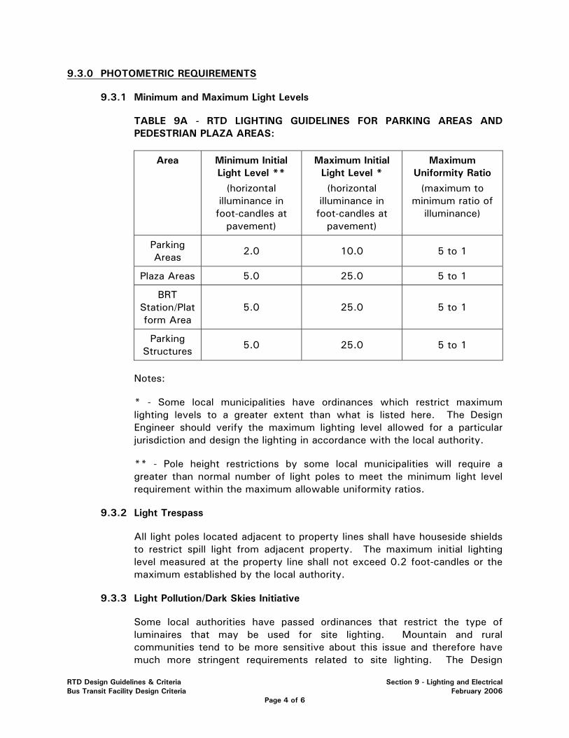
9.3.0 PHOTOMETRIC REQUIREMENTS
9.3.1 Minimum and Maximum Light Levels
TABLE 9A - RTD LIGHTING GUIDELINES FOR PARKING AREAS AND PEDESTRIAN PLAZA AREAS:
Area Minimum Initial Light Level **
(horizontal illuminance in foot-candles at
pavement)
Maximum Initial Light Level *
(horizontal illuminance in foot-candles at
pavement)
Maximum Uniformity Ratio
(maximum to minimum ratio of
illuminance)
Parking Areas
2.0 10.0 5 to 1
Plaza Areas 5.0 25.0 5 to 1
BRT Station/Platform Area
5.0 25.0 5 to 1
Parking Structures
5.0 25.0 5 to 1
Notes:
* - Some local municipalities have ordinances which restrict maximum lighting levels to a greater extent than what is listed here. The Design Engineer should verify the maximum lighting level allowed for a particular jurisdiction and design the lighting in accordance with the local authority.
** - Pole height restrictions by some local municipalities will require a greater than normal number of light poles to meet the minimum light level requirement within the maximum allowable uniformity ratios.
9.3.2 Light Trespass
All light poles located adjacent to property lines shall have houseside shields to restrict spill light from adjacent property. The maximum initial lighting level measured at the property line shall not exceed 0.2 foot-candles or the maximum established by the local authority.
9.3.3 Light Pollution/Dark Skies Initiative
Some local authorities have passed ordinances that restrict the type of luminaires that may be used for site lighting. Mountain and rural communities tend to be more sensitive about this issue and therefore have much more stringent requirements related to site lighting. The Design
RTD Design Guidelines & Criteria Section 9 - Lighting and Electrical Bus Transit Facility Design Criteria February 2006
Page 4 of 6
Engineer should investigate if these restrictions exist and design the lighting accordingly. In general, luminaires with downcast cut-off light distributions will be acceptable to most local authorities.
For light-sensitive areas, provisions can also be negotiated that will require/allow RTD to turn off up to half of the parking lot lights after the last bus serving the site has left for the night. The plaza lights are not to be included in this arrangement, but shall remain on during all hours of darkness.
9.4.0 CONDUITS
9.4.1 Plaza Lighting and Electrical Conduits
Conduit shall be provided to and from the mechanical room of the Drivers Relief Station (DRS) building, where the site electrical panel will be located.
Plaza lighting fixtures shall be linked with a minimum of three 1-inch conduit.
9.4.2 Parking Lot Lighting and Electrical Conduits
Parking lot lighting fixtures shall be connected with a minimum of three 1-inch conduit.
When security equipment is proposed to be located on a light pole, 2 additional 1-inch conduits (clearly marked “security conduit” shall be installed with pull strings. Those security conduits shall run from the hand hole on the light pole, through the light pole base, to a pull-box nearby. Two 2-inch conduits (clearly labeled “security conduit” shall be run between pull boxes, and connect to the security room of the DRS (or another approved location, if the site will have a separate security building).
9.5.0 EASEMENTS
9.5.1 Electric Easements
Whenever possible, exclusive electrical easements for other entities should be avoided. Non-exclusive, existing utility easements should be utilized where possible. Should an easement be required for the electrical service or transformer for another entity, it will require the approval of RTD’s Board of Directors.
During the design process, the Design Engineer shall coordinate service needs with Xcel, or other power providers for the proposed improvements.
Easements and license agreements are issued through RTD’s Real Property Division. These items shall be coordinated with RTD to ensure obtaining, issuing and recording the appropriate documents.
RTD Design Guidelines & Criteria Section 9 - Lighting and Electrical Bus Transit Facility Design Criteria February 2006
Page 5 of 6
9.6.0 AS-BUILT PLANS
9.6.1 Final “As-Built” Plans
Since RTD typically bids the lighting components of bus transit facilities as a “lump sum” item, “as-built” plan requirements shall be emphasized in the design plans and technical specifications.
RTD Design Guidelines & Criteria Section 9 - Lighting and Electrical Bus Transit Facility Design Criteria February 2006
Page 6 of 6
SECTION 10 – COMMUNICATIONS AND FARE COLLECTION
10.1.0 GENERAL ................................................................................................ 2 10.2.0 PARK-N-RIDES AND TRANSFER FACILITIES ................................................ 2
10.2.1 Communication and Fare Collection Device Locations ................................... 2 10.2.2 Plaza Signage........................................................................................... 2 10.2.3 Communication Elements .......................................................................... 2 10.2.4 Fare Collection Devices ............................................................................. 3
10.3.0 BRT AND STANDARD STREET SIDE BUS STOPS ......................................... 3
10.3.1 Sign Requirements.................................................................................... 3 10.3.2 Sign Location........................................................................................... 4 10.3.3 Communication Elements .......................................................................... 4 10.3.4 Fare Collection Devices ............................................................................. 4
10.4.0 INFORMATION KIOSKS............................................................................. 4
10.5.0 POWER AND CONDUIT REQUIREMENTS..................................................... 4
10.5.1 Power and Conduits.................................................................................. 4 10.5.2 Lighting and Electrical Conduits.................................................................. 5 10.5.3 Easements............................................................................................... 5
RTD Design Guidelines & Criteria Section 10 - Communications, Fare Collection & Power Bus Transit Facilities Design Criteria February 2006 Page 1 of 5
SECTION 10 – COMMUNICATIONS AND FARE COLLECTION
10.1.0 GENERAL
This Design Criteria establishes the minimum standards to be used in the design of RTD bus transit facilities. This section is intended to direct the Design Engineer in the design of communication elements, fare collection devices and associated appurtenances at all RTD bus transit facilities.
Communications elements are defined as those devices that provide and enable remote contact, announcements and message information sharing.
Fare collection devices are defined as all equipment and supporting infrastructure needed to accomplish collection or documentation of fares, which are not located on the designated transit vehicle.
Power requirements shall consist of all electrical alternating current (AC) power, equipment and conduits needed to energize a specific site.
10.2.0 PARK-N-RIDES AND TRANSFER FACILITIES
10.2.1 Communication and Fare Collection Device Locations
Park-n-Ride (pnR) communication elements and fare collection devices shall be located in areas that are convenient for the transit patron. They shall be near boarding areas, shelter areas and other public congregation and circulation areas. The size of the element or device shall be industry standard, but may vary depending upon specific needs and local ordinances.
Electronic communication information devices shall be located near bus boarding areas. At least one public telephone shall be installed at all major facilities (i.e., pnR, BRT superstops and transfer facilities). Additional phones may be installed as determined by patron volumes and frequency.
10.2.2 Plaza Signage
See Section 8.2.2 of this Manual.
10.2.3 Communication Elements
Public telephones shall be industry standard pay and credit card type.
Emergency telephones (blue phones) shall be installed adjacent to pay phones at bus boarding plaza areas. Emergency phones shall be installed on each level of parking structures and at the far end of pnRs that exceed 1000 spaces.
RTD Design Guidelines & Criteria Section 10 - Communications, Fare Collection & Power Bus Transit Facilities Design Criteria February 2006 Page 2 of 5
Public and emergency phones will typically be installed by the respective area telephone provider. Conduits for the phone lines shall be installed by the respective site contractor. Conduits shall be shown on the engineering drawings.
Communication elements shall also include a variety of Intelligent Transportation System (ITS) devices, which shall be integrated into each facility on a unique site-by-site basis in order to improve the overall system performance in terms of travel time, reliability, convenience, operational efficiency, safety and security. ITS items that shall be considered include: devices that enhance vehicle priority, operations and maintenance management, operator communications, real-time passenger information, and safety and security systems. SCADA systems shall be considered for all facilities. The final determination shall be coordinated with RTD during the concept design phase.
10.2.4 Fare Collection Devices
Bus fare collection currently occurs by submitting on-board cash directly into the bus fare box or by showing pre-purchased tickets, passes or transfers that are acknowledged by the bus operator.
Ticket vending machines (TVM) are not currently a bus transit fare collection option. However, with the introduction of bus rapid transit (BRT), and in an effort to improve and enhance fare collection efficiencies, “smart cards,” RFID readers and cards, and TVM are being evaluated by RTD for future bus service applications.
It is unlikely that street-side standard bus stops will utilize TVM. TVM are probable for BRT stops, major pnRs and major transfer facilities.
Design Engineers, in coordination with RTD, shall incorporate flexible options to include future TVM installations, which shall include consideration of device, location and conduit placement.
The Design Engineer shall coordinate with RTD on the need and design for TVM enclosures and canopies.
10.3.0 BRT AND STANDARD STREET SIDE BUS STOPS
10.3.1 Sign Requirements
Communication signage at BRT stops shall be similar to plaza areas for pnR and LRT station stops.
Street side standard bus stop signage is discussed in Section 8. In general electronic information signage will not be used at these locations unless technology and special circumstances dictate otherwise.
RTD Design Guidelines & Criteria Section 10 - Communications, Fare Collection & Power Bus Transit Facilities Design Criteria February 2006 Page 3 of 5
Sign panels, maps, schedule, route and fare information shall be provided and installed by RTD. Route number stickers shall be placed by RTD after the sign installation is complete.
Map and route information (schedules, maps and fare listing) shall be placed within cases that are part of bus stop passenger shelters or other required locations.
10.3.2 Sign Location
Bus information signage and communication devices shall be placed in areas that experience high passenger movement and shall comply with ADA requirements. If a passenger shelter is to be provided at the site, then a case for signs should be attached to the shelter.
See Section 8 for more information on signs at street side bus stops.
When a bus stop requires a new sign to be installed (on a new post), the sign should be located according to RTD Standard Drawings.
10.3.3 Communication Elements
A public telephone shall be placed at all major bus transit facilities and BRT stop stops, but not at standard street side bus stops.
Emergency telephones shall also be installed at major BRT stops, but not at standard street side stops.
10.3.4 Fare Collection Devices
The infrastructure for fare collection devices shall be included in the design of BRT stops, but not for standard street side stops.
10.4.0 INFORMATION KIOSKS
See Section 8.4.0 of this Manual.
10.5.0 POWER AND CONDUIT REQUIREMENTS
10.5.1 Power and Conduits
The placement of electrical devices and fixtures will be unique for each site and shall be coordinated through RTD’s Engineering Division. The power needs for each site shall be individually evaluated. A minimum 50% power reserve shall be designed for each site. All of the necessary transformers, electric panels and appurtenances shall be designed according to the unique needs of each site, and coordinated with the respective power utility company.
RTD Design Guidelines & Criteria Section 10 - Communications, Fare Collection & Power Bus Transit Facilities Design Criteria February 2006 Page 4 of 5
10.5.2 Lighting and Electrical Conduits
Conduit shall be provided to/from the mechanical or utility room of the DRS, where the site electrical panel shall be located.
Parking lot, plaza and station lighting, electrical fixtures, communication devices and TVM or other fare collection devices shall each be linked with a minimum of three 1-inch conduit that shall continue through appropriate pull-boxes, handholds and control panels.
ITS, SCADA, bus information variable message boards or public announcement devices shall include the installation of additional 1-inch conduits. All conduits shall include pull-ropes and shall be clearly marked for the intended use and so identified through the run from the source point of connection to the termination at the specified device.
As determined during the concept phase, security devices shall be placed on light or other specified poles. They shall include two (2) additional 1-inch conduits, marked “security conduit,” installed with pull ropes. Security conduits shall run from light pole hand holes, through the pole base, to an adjacent pull-box. Two (2) 2-inch conduits, labeled “security conduit,” shall run between pull boxes, hand holes or other similar access boxes and connect to the security room of the DRS building, or other approved location, if the site will have a separate security building. Pull boxes, hand holes or other similar access boxes, placed in plaza or other paved areas, shall be rated for vehicular loading
See Section 9 of this Manual for additional criteria.
10.5.3 Easements
See Section 9 of this Manual.
RTD Design Guidelines & Criteria Section 10 - Communications, Fare Collection & Power Bus Transit Facilities Design Criteria February 2006 Page 5 of 5
SECTION 11 - CONSTRUCTION DOCUMENTS
11.1.0 GENERAL.................................................................................................... 2 11.2.0 BID DOCUMENTS ........................................................................................ 3 11.3.0 CONSTRUCTION DRAWINGS........................................................................ 4 11.4.0 DRAWING SCALE ........................................................................................ 5 11.5.0 SPECIFICATIONS......................................................................................... 5 11.6.0 BID PACKAGE ............................................................................................. 5
RTD Design Guidelines & Criteria Section 11 - Construction Documents Bus Transit Facility Design Criteria February 2006
Page 1 of 5
SECTION 11 - CONSTRUCTION DOCUMENTS
11.1.0 GENERAL
Prior to obtaining construction plan approval, development improvement plans must be submitted and formally approved by local governing bodies, which may include any combination of a Planning Board, Planning and Zoning Commission/Committee, Public Works/Engineering, Board of Adjustment, City Council or County Commissioners. In rare cases, approval from a similarly designated State Commission or Board is required for developments on State land. Local development improvement approvals generally require the following reports and plans:
Concept Plan
Master Plan
Subdivision Plat, if not legally subdivided
Local Development Improvement Plan*
Drainage Report
Traffic Impact Study
Soils Report
Utility Report
Geologic Hazards
Archeological and Historic Artifacts Report
Others, as specified by local jurisdiction ordinance, code or development criteria
*The formal name of a local development improvement plan varies by jurisdiction. Common designations are Subdivision Improvement Plan (SIP), Final Development Plan (FDP), General Development Plan (GDP), and others as prescribed by the entity. The elements typically required with a development improvement plan drawings, but which may vary by jurisdiction, include the following items:
Cover Sheet
Existing Conditions Plan (survey)
Site Plan
Grading Plan
Erosion Control Plan
Utility Plan
Architectural Building Elevations
Photometric Plan
Landscape Plan
Construction Details
See RTD CADD Standards found under separate cover for examples and drawing style formats that shall apply in terms of placing a map index, scale, north arrow, title block, electronic file designations, etc.
RTD Design Guidelines & Criteria Section 11 - Construction Documents Bus Transit Facility Design Criteria February 2006
Page 2 of 5
11.2.0 BID DOCUMENTS
A set of Bid Document drawings shall typically contain the elements listed below. The set shall be broken into four key sections, General, Civil, Details and Systems. Depending upon the scope of the project, some of these elements may be eliminated or especially on smaller projects, combined onto a single sheet (i.e., Cover Sheet and Sheet Index). Conversely, large or complex projects may require several sheets per element.
General
Cover Sheet
Sheet Index
Standard Abbreviations and Symbols
RTD Standard Plan List
CDOT Standard Plan List
General Notes
Approximate Quantities
Civil
Survey Tabulation
Existing Conditions Plan (survey)
Demolition Plan
Detour / Temporary Access Plan
Erosion Control Plan (SWMP)
Erosion Control Details
Grading Plan
Site Plan
Plaza Plan
Horizontal and Vertical Control Sheet
Paving Plan
Paving Details
Plaza Paving Details
Pavement Markings and Signage Plan
Utility Plan and Profile
Storm Sewer
Water Service
Sanitary Sewer
Utility Details
Irrigation Plan
Irrigation Details
Landscape Plan
RTD Design Guidelines & Criteria Section 11 - Construction Documents Bus Transit Facility Design Criteria February 2006
Page 3 of 5
Landscape Details
Retaining Wall Layout
Retaining Wall Elevations
Retaining Wall Details
Drivers Relief Station
Foundation / Structural
Mechanical
Architectural
Traffic Signal Plan
Foundation / Structural
Traffic Signal Details
Details
Miscellaneous Details
ID Signs
Project Sign
Pedestrian Shelter Details
Systems
Electrical Legend and Schedules
Show all components from site transformer to area of use
Show contractor service connect/disconnect cabinet and switch
Electrical One-Line Diagram
Electrical Site Plan
Drivers Relief Station Electrical Plan
Electrical Details
11.3.0 CONSTRUCTION DRAWINGS
A set of Construction Drawings shall be exactly the same as the Bid Set, with the following exceptions:
Cover Sheet shall have the title of Bid Set replaced with Construction Drawings.
o Shall include the signatures of appropriate design Professional Engineer (PE) and RTD management.
o Select sheets within the set shall be signed and sealed by the appropriated discipline Professional Engineer or Registered Architect.
o Both half and full size drawings shall be signed and sealed.
As required, drawings shall be signed and sealed. This may also involve getting stamps or signatures from a local jurisdiction to indicate acceptance from building department, public works, engineering, etc.
RTD Design Guidelines & Criteria Section 11 - Construction Documents Bus Transit Facility Design Criteria February 2006
Page 4 of 5
Any sheets that were modified or added by addendum shall be inserted into the plan set with the original sheets removed and replaced.
If a sheet has been eliminated by addendum from the plan set, the name of the plan sheet shall be stricken through in the sheet index and the phrase INTENTIONALLY OMITTED added in a bold font and the sheet removed without renumbering the subsequent sheets in the set.
Revisions shall be noted and dated consecutively in the revisions block.
11.4.0 DRAWING SCALE
While projects vary greatly in size, a site plan for a typical bus transit facility is usually drawn at scales of 1 inch = 30 or 40 feet. Care must be taken when choosing the scale of a drawing to assure that details and text will be readable on a half size drawing. When it is necessary to break up a plan view onto several sheets in order to obtain a workable scale, a key map shall be included on each sheet, with the appropriate sheet on the key map being shaded in.
See RTD CADD Standards for additional information regarding drawing scales and font sizes.
11.5.0 SPECIFICATIONS
RTD Master Specifications will be the basis for the Technical Specifications that shall be included with all construction document packages. Design Engineers shall modify these Master Specifications to be site and project specific. Standardized examples of the Master Specifications can be found under a separate cover.
Where RTD Master Specifications do not exist for certain items of work, the Design Engineer shall be responsible for developing Technical Specifications (in CSI format) as required.
11.6.0 BID PACKAGE
The Technical Specifications, approved plans and contractual terms and conditions shall be included with all bid packages for constructing park-n-Rides and transfer facilities.
A summary of approximate planned quantities and an independent cost estimate shall be prepared, reviewed and approved prior to issuing a set of construction plans for bidding and construction. Cost estimates shall be signed and sealed by a Professional Engineer.
RTD Design Guidelines & Criteria Section 11 - Construction Documents Bus Transit Facility Design Criteria February 2006
Page 5 of 5
SECTION 12 – SYSTEM SAFETY AND SYSTEM SECURITY
12.1.0 GENERAL .................................................................................................. 2 12.2.0 APPLICABLE STANDARDS .......................................................................... 3 12.3.0 DEFINITION OF SAFETY CONDITIONS .......................................................... 4
12.3.1 Unacceptable Conditions ............................................................................ 4 12.3.2 Acceptable Conditions ............................................................................... 6
12.4.0 HAZARD IDENTIFICATION, ANALYSIS, AND RESOLUTION ............................. 7 12.5.0 PRELIMINARY HAZARD ANALYSIS (PHA) ..................................................... 7 12.6.0 SAFETY CERTIFICATION............................................................................. 8 12.7.0 BUS RAPID TRANSIT RIGHT-OF-WAY FENCING AND BARRIERS.................... 10 12.8.0 EMERGENCY ACCESS/EGRESS, STATION DESIGN, AND WALKWAYS........... 11 12.9.0 BRT GRADE CROSSINGS .......................................................................... 12 12.10.0 VIDEO SURVEILLANCE ............................................................................. 13 12.11.0 EMERGENCY TELEPHONES ....................................................................... 16 12.12.0 CRIME PREVENTION THROUGH ENVIRONMENTAL DESIGN .......................... 17 12.13.0 THREAT AND VULNERABILITY ANALYSIS AND RESOLUTION....................... 18
12.13.1 Severity Categories ............................................................................ 18 12.13.2 Transit Risk Assessment Levels ........................................................... 19 12.13.3 Probability Categories......................................................................... 19
12.14.0 PARK-N-RIDES, PARKING STRUCTURES, AND ENCLOSED UNDERGROUND OR BELOW GRADE TRANSIT FACILITIES ...................................................................... 22
12.14.1 Surface park-n-Rides .......................................................................... 2212.14.2 Parking Structures ............................................................................. 23 12.14.3 Underground and Below Grade Transit Facilities..................................... 24
12.15.0 PUBLICLY ACCESSIBLE RECEPTACLES...................................................... 25 12.16.0 CONFIGURATION MANAGEMENT ............................................................. 25
RTD Design Guidelines & Criteria Section 12 – System Safety and System Security Bus Transit Facilities Design Criteria February 2006
Page 1 of 25
SECTION 12 – SYSTEM SAFETY AND SYSTEM SECURITY
12.1.0 GENERAL
The design shall address system elements according to the requirements of the applicable standards listed. Should any standard or requirement conflict, the most stringent standard shall apply. In accordance with RTD’s System Safety and System Security Program Plan, RTD’s Executive Safety and Security Committee must review and accept all design and any subsequent changes or modifications. The RTD Project Manager and/or Design Engineer shall present design reviews to the RTD Executive Safety and Security Committee for acceptance as design milestones are reached. Additionally, any deviation from RTD’s design criteria must be approved by RTD’s Executive Safety and Security Committee, which consists of various division RTD Senior Managers (see 12.16.0).
Standards, specifications, regulations, design handbooks, safety design checklists and other sources of design guidance will be reviewed for pertinent safety design requirements applicable to the system. The design shall establish criteria derived from all applicable information. Some general system safety design requirements are:
• Identified hazards shall be eliminated or associated risk shall be reduced through design, including material selection or substitution. When potentially hazardous materials must be used, such materials selected shall pose the least risk throughout the life cycle of the system.
• Hazardous substances, components and operations shall be isolated from other activities, areas, personnel and incompatible materials.
• Equipment shall be located so that access during operations, servicing, maintenance, repair or adjustment minimizes personnel exposure to hazards (e.g. hazardous chemicals, high voltage, electromagnetic radiation, cutting edges or sharp points).
• Risk resulting from excessive environmental conditions (e.g. temperature, pressure, noise, toxicity, acceleration and vibration) shall be minimized.
• Risk resulting from human error in system operation and support shall be minimized as part of the design effort.
• In the case of risk from hazards that cannot be eliminated, alternatives that will minimize such risk shall be considered. (e.g. interlocks, redundancy, fail safe design, system protection, fire suppression and other protective measures, such as clothing, equipment, devices and procedures.)
• Power sources, controls and critical components of redundant subsystems shall be protected by physical separation or shielding, or by other suitable methods mutually agreeable to the design and RTD.
• When alternate design approaches cannot eliminate the hazard, safety and warning devices and warning and cautionary notes shall be provided in assembly, operations, maintenance and repair instructions, and distinctive markings shall be provided on hazardous components, equipment and facilities to ensure personnel and equipment protection. These shall be standardized in accordance with
RTD Design Guidelines & Criteria Section 12 – System Safety and System Security Bus Transit Facilities Design Criteria February 2006
Page 2 of 25
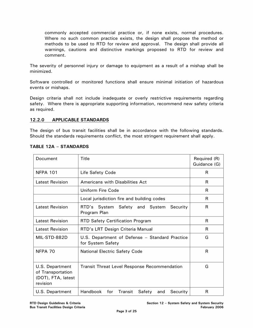
commonly accepted commercial practice or, if none exists, normal procedures. Where no such common practice exists, the design shall propose the method or methods to be used to RTD for review and approval. The design shall provide all warnings, cautions and distinctive markings proposed to RTD for review and comment.
The severity of personnel injury or damage to equipment as a result of a mishap shall be minimized.
Software controlled or monitored functions shall ensure minimal initiation of hazardous events or mishaps.
Design criteria shall not include inadequate or overly restrictive requirements regarding safety. Where there is appropriate supporting information, recommend new safety criteria as required.
12.2.0 APPLICABLE STANDARDS
The design of bus transit facilities shall be in accordance with the following standards. Should the standards requirements conflict, the most stringent requirement shall apply.
TABLE 12A – STANDARDS
Document Title Required (R) Guidance (G)
NFPA 101 Life Safety Code R
Latest Revision Americans with Disabilities Act R
Uniform Fire Code R
Local jurisdiction fire and building codes R
Latest Revision RTD’s System Safety and System Security Program Plan
R
Latest Revision RTD Safety Certification Program R
Latest Revision RTD’s LRT Design Criteria Manual R
MIL-STD-882D U.S. Department of Defense – Standard Practice for System Safety
G
NFPA 70 National Electric Safety Code
R
U.S. Department of Transportation (DOT), FTA, latest revision
Transit Threat Level Response Recommendation G
U.S. Department Handbook for Transit Safety and Security R
RTD Design Guidelines & Criteria Section 12 – System Safety and System Security Bus Transit Facilities Design Criteria February 2006
Page 3 of 25
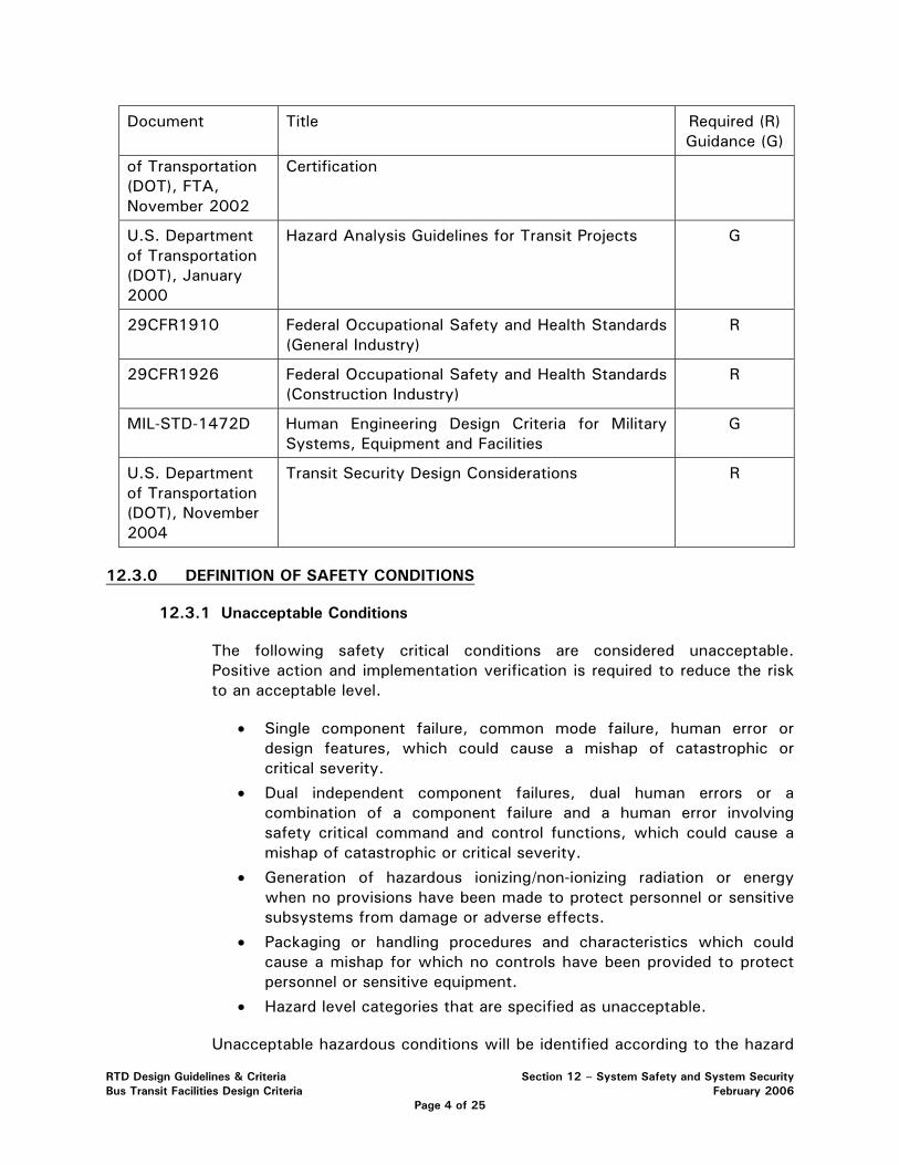
Document Title Required (R) Guidance (G)
of Transportation (DOT), FTA, November 2002
Certification
U.S. Department of Transportation (DOT), January 2000
Hazard Analysis Guidelines for Transit Projects
G
29CFR1910 Federal Occupational Safety and Health Standards (General Industry)
R
29CFR1926 Federal Occupational Safety and Health Standards (Construction Industry)
R
MIL-STD-1472D Human Engineering Design Criteria for Military Systems, Equipment and Facilities
G
U.S. Department of Transportation (DOT), November 2004
Transit Security Design Considerations R
12.3.0 DEFINITION OF SAFETY CONDITIONS
12.3.1 Unacceptable Conditions
The following safety critical conditions are considered unacceptable. Positive action and implementation verification is required to reduce the risk to an acceptable level.
• Single component failure, common mode failure, human error or design features, which could cause a mishap of catastrophic or critical severity.
• Dual independent component failures, dual human errors or a combination of a component failure and a human error involving safety critical command and control functions, which could cause a mishap of catastrophic or critical severity.
• Generation of hazardous ionizing/non-ionizing radiation or energy when no provisions have been made to protect personnel or sensitive subsystems from damage or adverse effects.
• Packaging or handling procedures and characteristics which could cause a mishap for which no controls have been provided to protect personnel or sensitive equipment.
• Hazard level categories that are specified as unacceptable.
Unacceptable hazardous conditions will be identified according to the hazard
RTD Design Guidelines & Criteria Section 12 – System Safety and System Security Bus Transit Facilities Design Criteria February 2006
Page 4 of 25
resolution matrix. Hazard classification at this level is a formal process for determining which hazards are acceptable, acceptable with review by management staff, undesirable or unacceptable. Hazard severity is a subjective measure of the worst credible mishap resulting from personnel error, environmental conditions, design inadequacies and/or procedural efficiencies for system, subsystem or component failure or malfunction. Hazard probability is defined as the probability that a specific hazard will occur during the planned life expectancy of the system element, subsystem or component. The categories of hazard severity, hazard probability and their definitions follow:
Hazard Severity Definition
• Catastrophic – Death or system loss
• Critical – Severe injury, severe occupational illness or major system damage
• Marginal – Minor injury, minor occupational illness or minor system damage
• Negligible – Less then minor injury, occupational illness or system damage
Hazard Probability Definition
• Frequent − Likely to occur frequently; continuously experienced
• Probable − Will occur several times in the life of an item; will occur frequently in fleet/inventory
• Occasional − Likely to occur sometime in the life of an item; will occur several times in fleet inventory
• Remote − Unlikely but possible to occur in the life of an item; unlikely but can be expected to occur in fleet/inventory
• Improbable − So unlikely, it can be assumed occurrence may not be experienced; unlikely to occur, but possible in fleet
The following table (of the RTD System Safety and System Security Program Plan) demonstrates the relationship between severity and probability to define an unacceptable hazardous condition.
RTD Design Guidelines & Criteria Section 12 – System Safety and System Security Bus Transit Facilities Design Criteria February 2006
Page 5 of 25
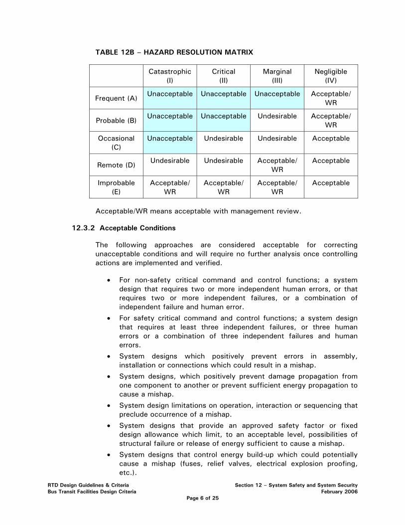
TABLE 12B – HAZARD RESOLUTION MATRIX
Catastrophic (I)
Critical (II)
Marginal (III)
Negligible (IV)
Frequent (A) Unacceptable Unacceptable Unacceptable Acceptable/
WR
Probable (B) Unacceptable Unacceptable Undesirable Acceptable/
WR
Occasional (C)
Unacceptable Undesirable Undesirable Acceptable
Remote (D) Undesirable Undesirable Acceptable/
WR Acceptable
Improbable (E)
Acceptable/WR
Acceptable/WR
Acceptable/WR
Acceptable
Acceptable/WR means acceptable with management review.
12.3.2 Acceptable Conditions
The following approaches are considered acceptable for correcting unacceptable conditions and will require no further analysis once controlling actions are implemented and verified.
• For non-safety critical command and control functions; a system design that requires two or more independent human errors, or that requires two or more independent failures, or a combination of independent failure and human error.
• For safety critical command and control functions; a system design that requires at least three independent failures, or three human errors or a combination of three independent failures and human errors.
• System designs which positively prevent errors in assembly, installation or connections which could result in a mishap.
• System designs, which positively prevent damage propagation from one component to another or prevent sufficient energy propagation to cause a mishap.
• System design limitations on operation, interaction or sequencing that preclude occurrence of a mishap.
• System designs that provide an approved safety factor or fixed design allowance which limit, to an acceptable level, possibilities of structural failure or release of energy sufficient to cause a mishap.
• System designs that control energy build-up which could potentially cause a mishap (fuses, relief valves, electrical explosion proofing, etc.).
RTD Design Guidelines & Criteria Section 12 – System Safety and System Security Bus Transit Facilities Design Criteria February 2006
Page 6 of 25
• System designs in which component failure can be temporarily tolerated because of residual strength or alternate operating paths so that operations can continue with a reduced but acceptable safety margin.
• System designs that positively alert the controlling personnel to a hazardous situation for which the capability for operator reaction has been provided.
• System designs which limit/control the use of hazardous materials.
12.4.0 HAZARD IDENTIFICATION, ANALYSIS, AND RESOLUTION
The Design Engineer shall develop and implement a Hazard Identification, Analysis, and Resolution process in accordance with the minimum criteria outlined in this section. The purpose of hazard analysis and resolution during the design and engineering phase of the project is several fold: to minimize or eliminate potential hazards; support early hazard identification; integrate safe operating procedures into system design and service; and provide for constant and continuous safety evaluation and assessment.
The Design Engineer shall use the requirements established in the following documents:
• APTA Guideline’s Hazard Resolution Matrix, American Public Transit Association, Manual for the Development of Bus System Safety Program Plans;
• Military Standard 882D (MIL-STD-882D); and
• Hazard Analysis Guidelines for Transit Projects, January 2000, U.S. Department of Transportation.
Subsequent to performing the initial hazard analysis, the Design Engineer shall recommend resolution or mitigation factors to reduce the classification of identified hazards and reclassify identified hazards considering the recommended resolution.
In applying resolution to identified hazards, the Design Engineer shall utilize the following system safety precedence:
• design for minimum risk
• incorporate safety devices
• provide warning devices; and
• develop procedures and training
12.5.0 PRELIMINARY HAZARD ANALYSIS (PHA)
The Preliminary Hazard Analysis (PHA) activity is the engineering function, which is performed to identify the hazards and their preliminary casual factors of the system in development. The hazards are formally documented to include information regarding the description of the hazard, casual factors, the effects of the hazard, and preliminary design considerations for hazard control by mitigating each cause. Performing the analysis includes assessing hazardous components, safety-related interfaces between subsystems, environmental constraints, operation, test and support activities, emergency procedures,
RTD Design Guidelines & Criteria Section 12 – System Safety and System Security Bus Transit Facilities Design Criteria February 2006
Page 7 of 25
test and support facilities, and safety-related equipment and safeguards.
The analysis also provides an initial assessment of hazard severity and probability of occurrence. The probability assessment at this point is usually subjective and qualitative. To support the tasks and activities of a safety effort, the “causes” of the root hazard must be assessed and analyzed. These causes should be separated in four separate categories:
• Hardware initiated causes
• Software initiated causes
• Human error initiated causes
• Human error causes that were influenced by software input to the user/operator
The Design Engineer shall conduct a PHA process for the project design. PHA work shall begin upon project initiation and continue throughout the project. The Design Engineer shall provide PHA progress reports according to a mutually agreeable schedule. The Design Engineer shall provide a draft and final PHA report on the preliminary engineering. Subsequent to the preliminary engineering, the Design Engineer shall conduct a draft and final PHA report on the final design.
The PHA document itself is a living document, which must be revised and updated as the system design and development progresses. It becomes the input document and information for all other hazard analyses performed on the system.
12.6.0 SAFETY CERTIFICATION
Safety certification is the process of verifying that system elements comply with a formal list of safety requirements. The requirements are defined by design criteria, contract requirements, applicable codes and industry safety standards. The Design Engineer shall develop a preliminary list of safety certifiable items and associated design requirements based on the preliminary engineering. The safety certification process shall apply to all elements of the system. Separate programs shall be developed, for light rail, for commuter rail and for BRT, as appropriate.
The Design Engineer shall identify those system elements and design standards to comply with the major steps in the safety certification process. These steps are implemented beginning with system design and continue through the start of revenue operation.
• Define and identify those safety-critical system elements to be certified
• Define and identify those security-related elements to be certified
• Define and develop a Certifiable Items List (CIL)
• Identify safety and security requirements for each certifiable item
• Verify and document design compliance with the safety and security requirements
The Design Engineer shall define and identify certifiable items relating to the elements listed in the following table.
RTD Design Guidelines & Criteria Section 12 – System Safety and System Security Bus Transit Facilities Design Criteria February 2006
Page 8 of 25
Safety Certifiable Elements (minimum)
1. Systems Elements
Buses and BRT Vehicles
Communications - Central Control System (CCS)
Comm- Supervisory Control & Data Acquisition (SCADA)
Ticket Vending Machines (TVM)
Maintenance Vehicles
Signaling - Bus Control
Bus Way
Bus Way Signals, Gates, Crossings, Entrances and Exits
Fire Protection & Suppression Systems
Auxiliary Vehicles
Grade Crossing Fixtures & Traffic Control System
Emergency Response Equipment
Intrusion Detection System
Signage
Tunnel Ventilation Control System (if req.)
2. Facility Elements
Tunnel
Structures
Bus Way
Each Station
Each at grade crossing
Each at grade crossing within each station
Garages/Parking Lots
Each Park-n-Ride
Control or Dispatch Center
Maintenance Facility
Art in Transit
3. Security Elements
RTD Design Guidelines & Criteria Section 12 – System Safety and System Security Bus Transit Facilities Design Criteria February 2006
Page 9 of 25
Video Surveillance (CCTV)
Parking Structure design
Park-n-Ride design
Incorporation of Crime Prevention Through Environmental Design (CPTED) applied to entire design
Station design
Emergency Telephones (and Radio)
Lighting – Stations, patron areas, park-n-Rides
Security of stairwells and elevators
Access Control
Portal Protection
Each certifiable item shall have an associated checklist or verification form consisting of a minimum of two major sections with the following minimum requirements.
Section 1 -- Design Requirements and Design Verification
The Design Engineer shall Identify and define each certifiable item, design requirement(s), requirement source, applicability, and provide name and signature of person and Design Engineer responsible for identifying element and defining requirements. The Design Engineer shall separately verify design requirements and provide name and signature of person and Design Engineer responsible for concurrence for design review. For each certifiable item, the Design shall define a basis from which to judge compliance with safety requirements.
The Design Engineer shall verify that design complies with identified requirements and supporting documentation, and shall provide name and signature of person responsible and Design Engineer responsible for design verification.
Section 2 -- Construction Verification
The Design Engineer shall supply a signature section on the form or checklist for future verification that construction complies with design through inspection, testing and the provision of documentation to serve as evidence that construction complies with design.
12.7.0 BUS RAPID TRANSIT RIGHT-OF-WAY FENCING AND BARRIERS
Right-of-Way (ROW) fencing and/or barriers shall be provided along the entire BRT alignment. The fencing and barriers shall be designed to address the following:
• act as a safety barrier to prevent vehicles, trucks, and other highway/roadway users from accidentally entering the BRT envelope;
• shall be of sufficient height to prevent trespass;
RTD Design Guidelines & Criteria Section 12 – System Safety and System Security Bus Transit Facilities Design Criteria February 2006
Page 10 of 25
• shall be designed to prevent debris and roadway snow removal activity (snow plows throwing slush, ice and other debris) from entering BRT envelope and transit station areas; and
• shall incorporate safety considerations on elevated sections with respect to fall protection and providing adequate space for maintenance-of-way workers.
There may be areas where different fencing or barriers may be more appropriate and aesthetic. In these areas, the fencing and/or barrier design shall be determined on a case by case basis and the design shall be accepted by the RTD System Safety Project Manager. Where different types of fencing/barriers connect, e.g. at-grade to elevated transition points, or at-grade to retaining wall transition points, the design shall accommodate a seamless transition accommodating the integrity of the fence/barrier. For example, a section of ROW may have a three foot jersey barrier with a six foot fence (total height nine feet) that meets up to a three foot MSE wall with a three foot fence (total height six feet). The fencing shall be designed so it tapers from the higher requirement to the lower requirement and meets the performance requirement of this section. No gaps between transitions are allowed. For example, if the fencing/barrier terminates at a bridge monument, the fencing shall be attached to the monument.
12.8.0 EMERGENCY ACCESS/EGRESS, STATION DESIGN, AND WALKWAYS
The design shall include emergency access and egress points along the transit way using NFPA 130 as guidance. The design shall identify emergency access and egress locations and shall provide a list or matrix of the necessary elements to be provided at each exit, such as lighting, signage, lock hardware, intrusion detection, and other elements as required by NFPA 130 and local jurisdictions. The design shall incorporate a preliminary emergency evacuation plan and diagrams for the transit way, including each station, identifying primary and secondary evacuation routes and points of safety.
BRT station design shall meet the “Means of Egress” requirements for stations as identified in NFPA 130. The Design Engineer shall provide a draft and final Means of Egress Report for all BRT stations documenting that station design meets or exceeds all criteria listed in NFPA 130. The report shall include all calculations, supporting documentation, engineering drawings and other information necessary to demonstrate compliance with NFPA 130. For calculation of occupant load, the Design Engineer shall use projected ridership figures or maximum capacities based on the operating plan(s). Each station shall have a minimum of two main access/egress points remotely located from one another. There shall be sufficient exit lanes to evacuate the station occupant load, as defined in NFPA 130, from the station platform in 4 minutes or less. The maximum travel distance to an exit from any point on the platform shall not exceed 300 feet. Stations shall also be designed to permit evacuation from the most remote point on the platform to a point of safety in 6 minutes or less.
The design shall incorporate a walk surface or other suitable means for passengers to evacuate a bus at any point along the transit way so that they can proceed to the nearest station or other point of safety per NFPA requirements.
RTD Design Guidelines & Criteria Section 12 – System Safety and System Security Bus Transit Facilities Design Criteria February 2006
Page 11 of 25
12.9.0 BRT GRADE CROSSINGS
The design shall incorporate approaches that minimize hazards and risks to bus transit, pedestrians, bicyclists and motor vehicle operators. The primary method to minimize grade crossing hazards is to eliminate at grade crossings or minimize the number of at grade BRT crossings.
Where planning and design does not allow for the elimination of an at grade crossing, the following system safety precedence shall be applied: design for minimum risk, incorporate safety devices, and provide warning devices. A combination of active grade crossing warning devices and passive warning devices is preferred to solely using passive warning devices. Active warning devices include: gates, bells, flashing lights and grade crossing indicators for train operators. Passive warning devices include signage and pavement markings.
Design of each at grade crossing shall be subject to the circumstances of that crossing and its relation to the transit corridor. In considering appropriate control and warning devices, consideration shall be given to the following: type of alignment (exclusive, semi-exclusive, or shared ROW); configuration and geometry of crossing (angled or mid-block crossing; operating speed of all users; line of sight of all users; pedestrian activity; school zone; and extreme surges (pedestrians and vehicles).
To enhance pedestrian and bicycle safety at crossings, consideration shall be given to the use of channeling. The purpose of channeling is to create a physical barrier that prevents or discourages persons from taking shortcuts or from crossing the track way in a risky or unauthorized manner. Effective channeling may be developed through the use of fencing, landscaping, bollard and chain, railing, sidewalks or other methods. In all cases, a channeling method that enhances sight lines to an approaching train shall be selected.
Additional elements that may improve pedestrian and bicycle safety at crossings include: swing gates, pedestrian barriers, and automatic pedestrian gates. The purpose of a swing gate is to slow persons who are hurriedly approaching the track way. Swing gate operation depends upon the judgment of the individual. It is not electrically interconnected into approaching train or vehicular traffic signal systems. Swing gates may be appropriate where:
• There is a high likelihood that persons will hurriedly cross the track way, or sight lines and distance are restricted, and
• Channeling or other barriers reasonably prevent persons from bypassing the swing gates, and
• Acceptable provisions for opening the gates by disabled persons can be provided.
Swing gates shall open away from the tracks. Pedestrians shall pull the gate to open it and enter the track way. Gates shall also permit quick exit from the track way, automatically close after use, and be light and easy to operate by all persons.
RTD Design Guidelines & Criteria Section 12 – System Safety and System Security Bus Transit Facilities Design Criteria February 2006
Page 12 of 25
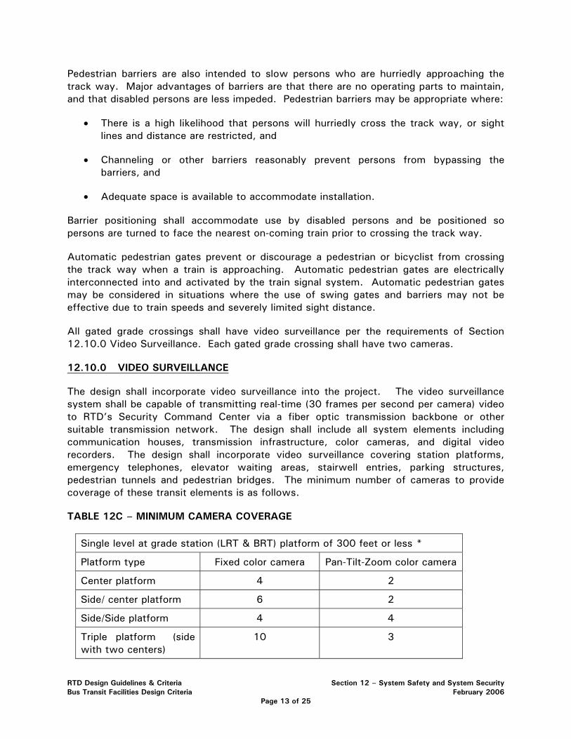
Pedestrian barriers are also intended to slow persons who are hurriedly approaching the track way. Major advantages of barriers are that there are no operating parts to maintain, and that disabled persons are less impeded. Pedestrian barriers may be appropriate where:
• There is a high likelihood that persons will hurriedly cross the track way, or sight lines and distance are restricted, and
• Channeling or other barriers reasonably prevent persons from bypassing the barriers, and
• Adequate space is available to accommodate installation.
Barrier positioning shall accommodate use by disabled persons and be positioned so persons are turned to face the nearest on-coming train prior to crossing the track way.
Automatic pedestrian gates prevent or discourage a pedestrian or bicyclist from crossing the track way when a train is approaching. Automatic pedestrian gates are electrically interconnected into and activated by the train signal system. Automatic pedestrian gates may be considered in situations where the use of swing gates and barriers may not be effective due to train speeds and severely limited sight distance.
All gated grade crossings shall have video surveillance per the requirements of Section 12.10.0 Video Surveillance. Each gated grade crossing shall have two cameras.
12.10.0 VIDEO SURVEILLANCE
The design shall incorporate video surveillance into the project. The video surveillance system shall be capable of transmitting real-time (30 frames per second per camera) video to RTD’s Security Command Center via a fiber optic transmission backbone or other suitable transmission network. The design shall include all system elements including communication houses, transmission infrastructure, color cameras, and digital video recorders. The design shall incorporate video surveillance covering station platforms, emergency telephones, elevator waiting areas, stairwell entries, parking structures, pedestrian tunnels and pedestrian bridges. The minimum number of cameras to provide coverage of these transit elements is as follows.
TABLE 12C – MINIMUM CAMERA COVERAGE
Single level at grade station (LRT & BRT) platform of 300 feet or less *
Platform type Fixed color camera Pan-Tilt-Zoom color camera
Center platform 4 2
Side/ center platform 6 2
Side/Side platform 4 4
Triple platform (side with two centers)
10 3
RTD Design Guidelines & Criteria Section 12 – System Safety and System Security Bus Transit Facilities Design Criteria February 2006
Page 13 of 25
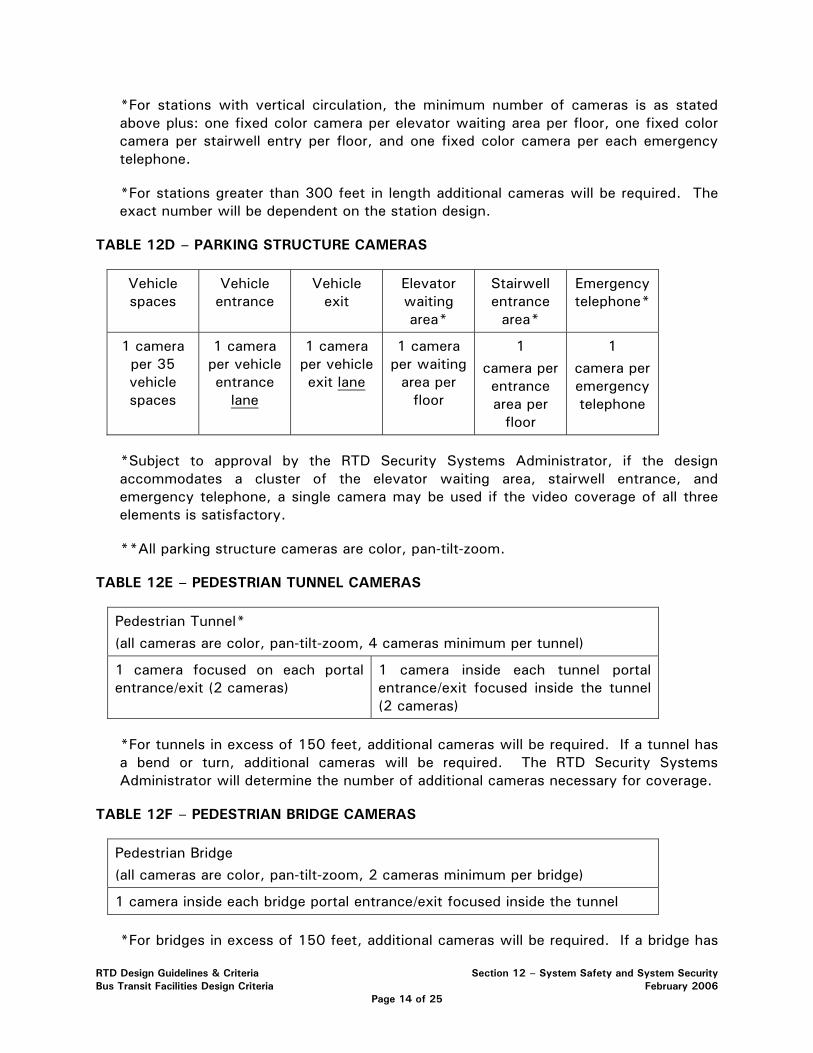
*For stations with vertical circulation, the minimum number of cameras is as stated above plus: one fixed color camera per elevator waiting area per floor, one fixed color camera per stairwell entry per floor, and one fixed color camera per each emergency telephone.
*For stations greater than 300 feet in length additional cameras will be required. The exact number will be dependent on the station design.
TABLE 12D – PARKING STRUCTURE CAMERAS
Vehicle spaces
Vehicle entrance
Vehicle exit
Elevator waiting area*
Stairwell entrance
area*
Emergency telephone*
1 camera per 35 vehicle spaces
1 camera per vehicle entrance
lane
1 camera per vehicle exit lane
1 camera per waiting
area per floor
1
camera per entrance area per
floor
1
camera per emergency telephone
*Subject to approval by the RTD Security Systems Administrator, if the design accommodates a cluster of the elevator waiting area, stairwell entrance, and emergency telephone, a single camera may be used if the video coverage of all three elements is satisfactory.
**All parking structure cameras are color, pan-tilt-zoom.
TABLE 12E – PEDESTRIAN TUNNEL CAMERAS
Pedestrian Tunnel*
(all cameras are color, pan-tilt-zoom, 4 cameras minimum per tunnel)
1 camera focused on each portal entrance/exit (2 cameras)
1 camera inside each tunnel portal entrance/exit focused inside the tunnel (2 cameras)
*For tunnels in excess of 150 feet, additional cameras will be required. If a tunnel has a bend or turn, additional cameras will be required. The RTD Security Systems Administrator will determine the number of additional cameras necessary for coverage.
TABLE 12F – PEDESTRIAN BRIDGE CAMERAS
Pedestrian Bridge
(all cameras are color, pan-tilt-zoom, 2 cameras minimum per bridge)
1 camera inside each bridge portal entrance/exit focused inside the tunnel
*For bridges in excess of 150 feet, additional cameras will be required. If a bridge has
RTD Design Guidelines & Criteria Section 12 – System Safety and System Security Bus Transit Facilities Design Criteria February 2006
Page 14 of 25
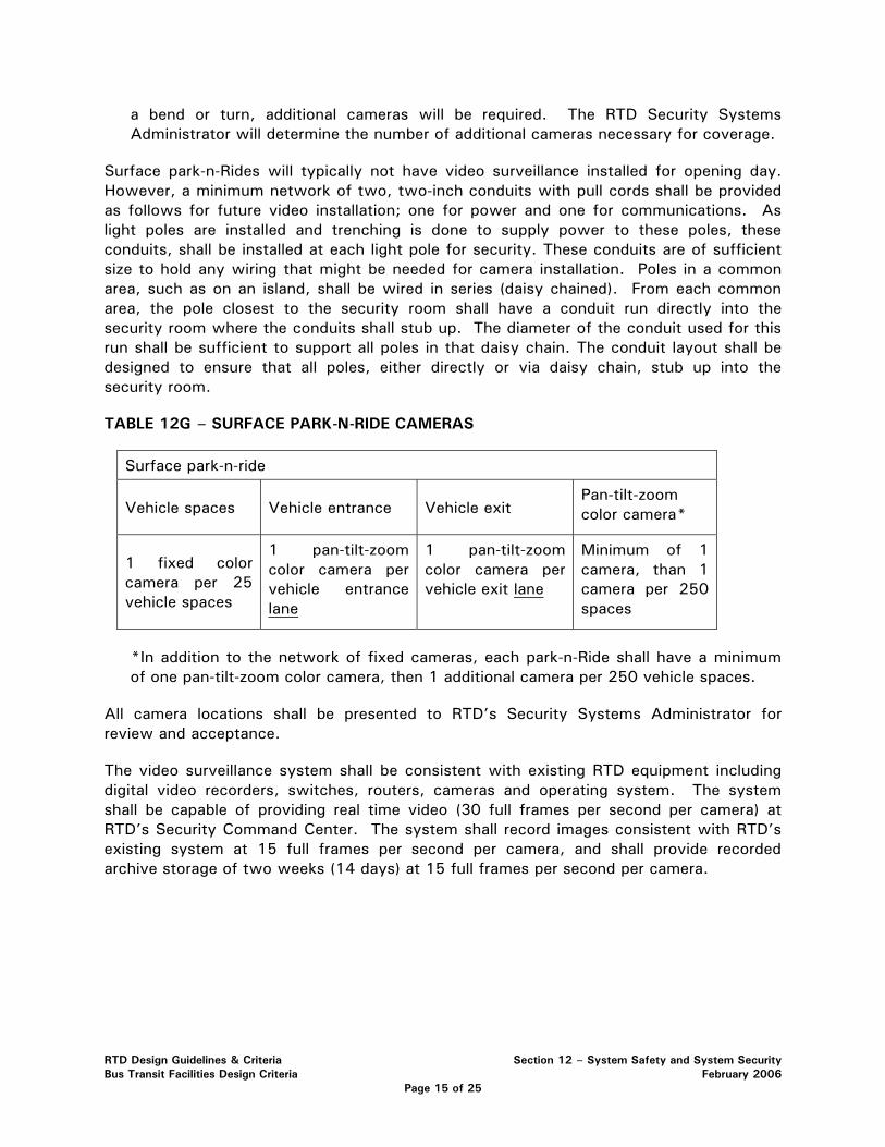
a bend or turn, additional cameras will be required. The RTD Security Systems Administrator will determine the number of additional cameras necessary for coverage.
Surface park-n-Rides will typically not have video surveillance installed for opening day. However, a minimum network of two, two-inch conduits with pull cords shall be provided as follows for future video installation; one for power and one for communications. As light poles are installed and trenching is done to supply power to these poles, these conduits, shall be installed at each light pole for security. These conduits are of sufficient size to hold any wiring that might be needed for camera installation. Poles in a common area, such as on an island, shall be wired in series (daisy chained). From each common area, the pole closest to the security room shall have a conduit run directly into the security room where the conduits shall stub up. The diameter of the conduit used for this run shall be sufficient to support all poles in that daisy chain. The conduit layout shall be designed to ensure that all poles, either directly or via daisy chain, stub up into the security room.
TABLE 12G – SURFACE PARK-N-RIDE CAMERAS
Surface park-n-ride
Vehicle spaces Vehicle entrance Vehicle exit Pan-tilt-zoom color camera*
1 fixed color camera per 25 vehicle spaces
1 pan-tilt-zoom color camera per vehicle entrance lane
1 pan-tilt-zoom color camera per vehicle exit lane
Minimum of 1 camera, than 1 camera per 250 spaces
*In addition to the network of fixed cameras, each park-n-Ride shall have a minimum of one pan-tilt-zoom color camera, then 1 additional camera per 250 vehicle spaces.
All camera locations shall be presented to RTD’s Security Systems Administrator for review and acceptance.
The video surveillance system shall be consistent with existing RTD equipment including digital video recorders, switches, routers, cameras and operating system. The system shall be capable of providing real time video (30 full frames per second per camera) at RTD’s Security Command Center. The system shall record images consistent with RTD’s existing system at 15 full frames per second per camera, and shall provide recorded archive storage of two weeks (14 days) at 15 full frames per second per camera.
RTD Design Guidelines & Criteria Section 12 – System Safety and System Security Bus Transit Facilities Design Criteria February 2006
Page 15 of 25

12.11.0 EMERGENCY TELEPHONES
The design shall incorporate emergency telephones into the project. The emergency telephones shall be consistent with existing RTD units and meet performance requirements of RTD’s existing emergency telephone network. The design shall incorporate emergency telephones covering station platforms, elevator waiting areas, stairwell entries, parking structures, park-n-Rides, pedestrian tunnels and pedestrian bridges. Emergency telephones shall be placed as follows.
TABLE 12H – EMERGENCY TELEPHONES AT STATIONS
Single level at grade station platform* (LRT & BRT)
Platform type Emergency telephones
Center platform 1
Side/ center platform 1
Side/Side platform 2
Triple platform
(side with two centers)
2
* For stations with vertical circulation, one additional emergency telephone shall be placed per floor.
TABLE 12I - EMERGENCY TELEPHONES AT PARKING STRUCTURES
Parking Structure
Elevator waiting area* Stairwell entrance area*
1 emergency telephone per waiting area per floor
1 emergency telephone per stairwell entrance area per floor (if two stairwells, then 2 ET’s per floor, etc.)
Subject to approval by the RTD Security Systems Administrator, if the design accommodates the elevator waiting area and stairwell entrance being adjacent to one another, a single emergency telephone may be used for that location.
For surface park-n-Rides, a minimum of one emergency telephone shall be placed in the design, and then one additional emergency telephone per each 300 spaces. This placement and frequency of emergency phones shall be coordinated with RTD during the concept and preliminary engineering design.
If pedestrian overpasses or underpasses are incorporated into design, a minimum of one emergency telephone shall be provided for each overpass/underpass. If the overpass or bridge is isolated from other transit elements, additional emergency telephones may be necessary.
RTD Design Guidelines & Criteria Section 12 – System Safety and System Security Bus Transit Facilities Design Criteria February 2006
Page 16 of 25
The emergency telephone when activated shall connect to 911 and also send notification and audible listening capability to RTD rail control and RTD Security Command Center.
Installed Emergency Telephones shall be constructed pursuant to a minimum NEMA 3R rating (see below) and be Underwriter Laboratory and FCC approved and ADA compliant. The phones shall draw power from the phone line and require no additional power line attachments. The phones shall be capable of off-site live monitoring of emergency conversations. The emergency phones shall be part of a networked management system that is operated by a PC, XP Windows compatible or newer. The software management system will:
• Establish an automatic connection with each phone on a prearranged schedule. Phones will be tested at least one time in every twenty-four hours. The connection shall be initiated either by the PC or the telephone.
• Print an exception report at designated intervals highlighting use and malfunctions.
• Archive and maintain all reporting both of normal functioning and malfunctions.
• Log and archive all call activity at each phone.
• Identify all call activity by date and time, type of activity, and location of data within memory.
• Establish Automatic Maintenance Monitoring which reports stuck buttons, power interruption, microprocessor testing, call interrupt, handset integrity and functioning, handset off hook notification and phone line current.
NEMA 3R – Enclosures constructed for either indoor or outdoor use to provide a degree of protection to personnel against incidental contact with the enclosed equipment; to provide a degree of protection against falling dirt, rain, sleet, snow, and that will be undamaged by the external formation of ice on the enclosure. Phones will operate in a temperature range of -40˚C to +60˚C.
All emergency telephone locations will be presented to RTD’s Security Systems Administrator for review and acceptance.
12.12.0 CRIME PREVENTION THROUGH ENVIRONMENTAL DESIGN
The design shall incorporate Crime Prevention Through Environmental Design (CPTED) strategies to the entire design. The purpose of CPTED is to minimize potential threats and vulnerabilities to the transit system, facilities and patrons and maximize safety and security through engineering and design. Good CPTED strategies include: maximizing visibility of people, parking areas, patron flow areas and building/structure areas; providing adequate lighting minimizing shadows; graffiti guards; Mylar shatter guard protection for glass windows; landscape plantings that maximize visibility; gateway treatments; decorative fencing; perimeter control; fencing; minimizing park-n-ride and parking structure access points; elimination of structural hiding places; open lines of sight; visible stairwells
RTD Design Guidelines & Criteria Section 12 – System Safety and System Security Bus Transit Facilities Design Criteria February 2006
Page 17 of 25
and elevators meaning the exterior walls are constructed of transparent material; and painting with light.
Examples of CPTED strategy include:
• Adequate lighting of all areas appropriate for their use including perimeter lighting in park-n-Rides so the edge of the park-n-Ride is illuminated the same as the rest of the park-n-Ride (refer to station design criteria for lighting levels).
• When using shrubs, use species with a maximum height or spread that will minimize visibility obstructions. The preliminary design shall be approved by RTD prior to final design and implementation.
• When using trees, use deciduous trees with branches no lower than six feet from ground surface.
The design shall incorporate CPTED strategies into the Threat and Vulnerability Analysis and Resolution process described in the following section, 12.13.0 Threat and Vulnerability Analysis and Resolution.
12.13.0 THREAT AND VULNERABILITY ANALYSIS AND RESOLUTION
The design shall incorporate a Threat and Vulnerability Analysis and Resolution process in accordance with the minimum criteria outlined in this section. A risk assessment is a comprehensive study of a system to identify those components most vulnerable to disruption or destruction and to assess the likely impact that such disruption or destruction would have on passengers, employees, and the RTD system. Threat and vulnerability analysis (TVA) work shall begin upon project initiation and continue throughout the project. The design shall incorporate TVA progress reports according to a mutually agreeable schedule. The design shall include a draft and final TVA report on the preliminary engineering. The TVA document itself is a living document, which must be revised and updated as the system design and development progresses. It becomes the input document and information for all other TVA performed on the system.
The process shall assign values to design elements based on their criticality to the transit system operations. The four level risk classification system listed below will be used to assess risk levels.
12.13.1 Severity Categories
See Section 12.3.1, Hazard Severity Definitions.
RTD Design Guidelines & Criteria Section 12 – System Safety and System Security Bus Transit Facilities Design Criteria February 2006
Page 18 of 25
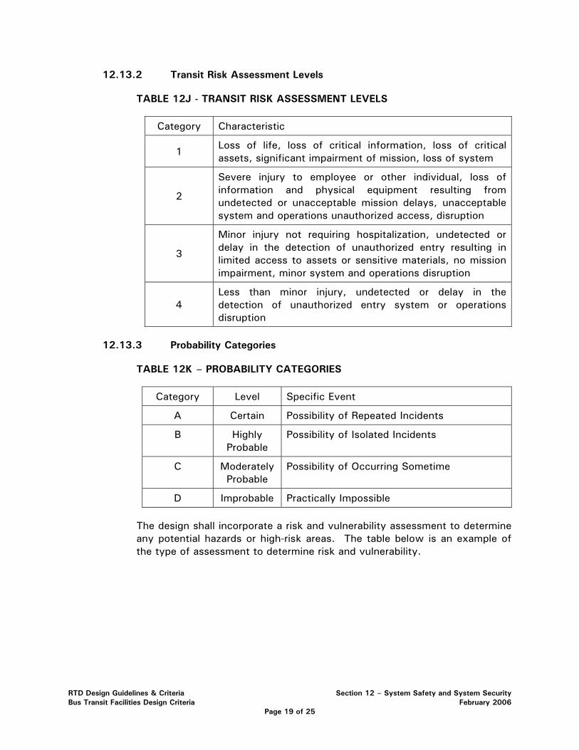
12.13.2 Transit Risk Assessment Levels
TABLE 12J - TRANSIT RISK ASSESSMENT LEVELS
Category Characteristic
1 Loss of life, loss of critical information, loss of critical assets, significant impairment of mission, loss of system
2
Severe injury to employee or other individual, loss of information and physical equipment resulting from undetected or unacceptable mission delays, unacceptable system and operations unauthorized access, disruption
3
Minor injury not requiring hospitalization, undetected or delay in the detection of unauthorized entry resulting in limited access to assets or sensitive materials, no mission impairment, minor system and operations disruption
4 Less than minor injury, undetected or delay in the detection of unauthorized entry system or operations disruption
12.13.3 Probability Categories
TABLE 12K – PROBABILITY CATEGORIES
Category Level Specific Event
A Certain Possibility of Repeated Incidents
B Highly Probable
Possibility of Isolated Incidents
C Moderately Probable
Possibility of Occurring Sometime
D Improbable Practically Impossible
The design shall incorporate a risk and vulnerability assessment to determine any potential hazards or high-risk areas. The table below is an example of the type of assessment to determine risk and vulnerability.
RTD Design Guidelines & Criteria Section 12 – System Safety and System Security Bus Transit Facilities Design Criteria February 2006
Page 19 of 25
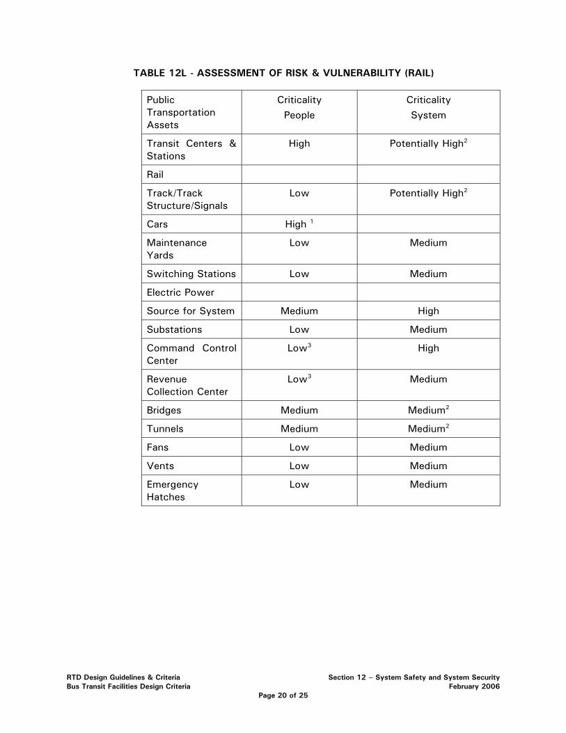
TABLE 12L - ASSESSMENT OF RISK & VULNERABILITY (RAIL)
Public Transportation Assets
Criticality
People
Criticality
System
Transit Centers & Stations
High Potentially High2
Rail
Track/Track Structure/Signals
Low Potentially High2
Cars High 1
Maintenance Yards
Low Medium
Switching Stations Low Medium
Electric Power
Source for System Medium High
Substations Low Medium
Command Control Center
Low3 High
Revenue Collection Center
Low3 Medium
Bridges Medium Medium2
Tunnels Medium Medium2
Fans Low Medium
Vents Low Medium
Emergency Hatches
Low Medium
RTD Design Guidelines & Criteria Section 12 – System Safety and System Security Bus Transit Facilities Design Criteria February 2006
Page 20 of 25
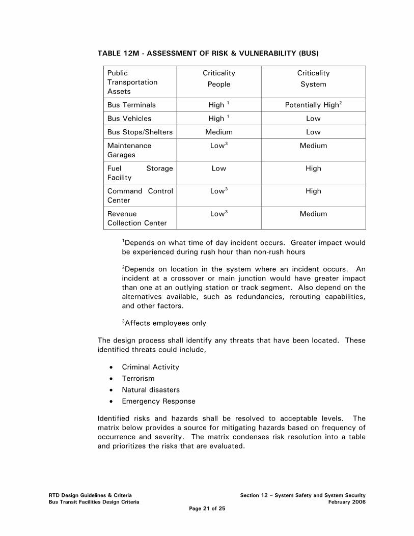
TABLE 12M - ASSESSMENT OF RISK & VULNERABILITY (BUS)
Public Transportation Assets
Criticality
People
Criticality
System
Bus Terminals High 1 Potentially High2
Bus Vehicles High 1 Low
Bus Stops/Shelters Medium Low
Maintenance Garages
Low3 Medium
Fuel Storage Facility
Low High
Command Control Center
Low3 High
Revenue Collection Center
Low3 Medium
1Depends on what time of day incident occurs. Greater impact would be experienced during rush hour than non-rush hours
2Depends on location in the system where an incident occurs. An incident at a crossover or main junction would have greater impact than one at an outlying station or track segment. Also depend on the alternatives available, such as redundancies, rerouting capabilities, and other factors.
3Affects employees only
The design process shall identify any threats that have been located. These identified threats could include,
• Criminal Activity
• Terrorism
• Natural disasters
• Emergency Response
Identified risks and hazards shall be resolved to acceptable levels. The matrix below provides a source for mitigating hazards based on frequency of occurrence and severity. The matrix condenses risk resolution into a table and prioritizes the risks that are evaluated.
RTD Design Guidelines & Criteria Section 12 – System Safety and System Security Bus Transit Facilities Design Criteria February 2006
Page 21 of 25
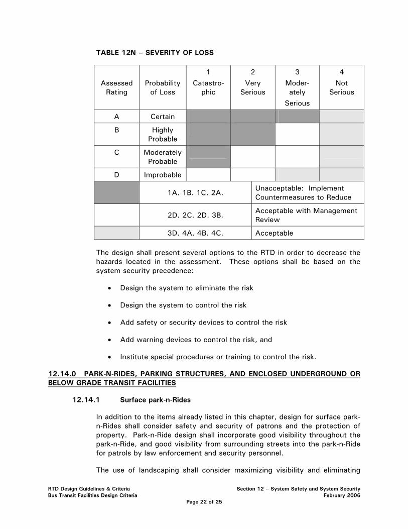
TABLE 12N – SEVERITY OF LOSS
Assessed Rating
Probability of Loss
1
Catastro-phic
2
Very Serious
3
Moder-ately
Serious
4
Not Serious
A Certain
B Highly Probable
C Moderately Probable
D Improbable
1A. 1B. 1C. 2A.
Unacceptable: Implement Countermeasures to Reduce
2D. 2C. 2D. 3B.
Acceptable with Management Review
3D. 4A. 4B. 4C. Acceptable
The design shall present several options to the RTD in order to decrease the hazards located in the assessment. These options shall be based on the system security precedence:
• Design the system to eliminate the risk
• Design the system to control the risk
• Add safety or security devices to control the risk
• Add warning devices to control the risk, and
• Institute special procedures or training to control the risk.
12.14.0 PARK-N-RIDES, PARKING STRUCTURES, AND ENCLOSED UNDERGROUND OR BELOW GRADE TRANSIT FACILITIES
12.14.1 Surface park-n-Rides
In addition to the items already listed in this chapter, design for surface park-n-Rides shall consider safety and security of patrons and the protection of property. Park-n-Ride design shall incorporate good visibility throughout the park-n-Ride, and good visibility from surrounding streets into the park-n-Ride for patrols by law enforcement and security personnel.
The use of landscaping shall consider maximizing visibility and eliminating
RTD Design Guidelines & Criteria Section 12 – System Safety and System Security Bus Transit Facilities Design Criteria February 2006
Page 22 of 25
hiding places and shadows. Shrubs shall not impede visibility in height and trees shall bear no branches below 6 feet from ground surface. Evergreen trees shall only be used on a limited basis and shall be placed in such a manner that hiding spaces and visual obstructions are not created. Landscape placement shall be subject to approval by the RTD Security Systems Administrator.
Adequate and appropriate lighting is the single most effective deterrent for minimizing crime at park-n-Rides. Lighting shall be provided in accordance with the criteria provided in Section 9 of this Manual. The design shall address perimeter lighting by including placement of light poles around the perimeter of the park-n-Ride.
The control and design of park-n-Ride entrances and exits is important to maintaining security of park-n-Rides. Entrances and exits shall be limited to as few as practically possible to control access and egress from the park-n-Ride site and minimize the number of entrance and exit cameras. To compliment the effective use of video surveillance, traffic calming features (i.e. speed bumps) shall be considered at entrances and exits on a case-by-case basis to slow the vehicles as they enter and exit to allow adequate time for automobile license plates to be captured by video surveillance. Where speed bumps are used for this purposes, they shall include two speed bumps separated by one and one half standard vehicle lengths.
12.14.2 Parking Structures
In addition to the items already listed in this chapter, design for parking structures shall consider safety and security of patrons and the protection of property. Parking structure design shall incorporate good visibility throughout the structure, and good visibility from surrounding streets into the structure for patrols by law enforcement and security personnel. Walls inside the structure shall be limited to increase visibility and minimize hiding places throughout the structure. Openings in interior walls between levels or ramps shall be protected by mesh or chain link fencing. Openings in exterior walls at the ground level and at below grade level shall be protected by mesh, chain link fence or other treatment to prevent pedestrians from entering or exiting the structure through these openings.
The control and design of parking structure entrances and exits is important to maintaining security of the structures. Entrances and exits shall be limited to as few as practically possible to control access and egress from the structure and minimize the number of entrance and exit cameras.
Stairwell and elevator design shall maximize the interior visibility of the stairwell, elevator and elevator shaft. Materials of wall construction for these elements shall be transparent such as glass and allow visibility from at least three sides.
RTD Design Guidelines & Criteria Section 12 – System Safety and System Security Bus Transit Facilities Design Criteria February 2006
Page 23 of 25
Each parking structure shall include a security room/office for security or law enforcement personnel.
Parking structures shall have minimum lighting levels of 5 foot candles measured at pavement.
12.14.3 Underground and Below Grade Transit Facilities
Enclosed, underground and below grade transit facilities present unique security design challenges. Design of these facilities shall maximize patron safety and security by the inclusion of counterterrorism measures. Each enclosed, underground or below grade facility shall be covered by video surveillance including: its perimeter; portals, entrances and exits; its interior; and fare vending areas. Patron station areas in these facilities shall be designed as paid fare zones. Thus, patron circulation design shall consider the availability to purchase fare media prior to entering the paid fare zones.
Where facilities serve more than one mode of transportation, the design shall incorporate a means to physically separate modal areas using automatic doors. Each modal area shall also have a separate ventilation system. This design shall allow one modal area to operate in the event of a major incident occurring in an adjacent modal area and prevent cross contamination.
Facility access control is an important aspect of design and shall be designed as follows. All access points (entrances and exits) to the facility and all interior doors shall be controlled by proximity reader access control. The proximity reader access control system shall be a Lenel system as currently installed at RTD facilities and shall be networked into the existing system. All access points or portals capable of accommodating a motor vehicle shall be equipped with automatic portal protection that will prevent unauthorized vehicles from entering the facility. The portal protection shall have a K-12 rating, shall include a guard shack, and shall be located at a minimum distance of 150 feet from the facility entry portal. Portals for train access shall include intrusion detection capable of distinguishing between an authorized train and any other unauthorized vehicle or person attempting to gain access through the train portal. Intrusion detection alarm notification shall be sent to light rail central control and RTD Security Command Center. The facility design shall incorporate a means to establish a vehicle checkpoint at a minimum distance of 150 feet from each facility vehicle entry portal.
The design shall protect the facility from progressive collapse. In the event of an internal explosion, the design shall prevent progressive collapse due to the loss of one primary column. Column design shall consider sizing, reinforcement or protection so that the threat charge will not cause the column to be critically damaged.
Loading docks and shipping/receiving areas are prohibited in underground
RTD Design Guidelines & Criteria Section 12 – System Safety and System Security Bus Transit Facilities Design Criteria February 2006
Page 24 of 25
and below grade facilities. All deliveries shall be accommodated for at the exterior of the facility above grade.
Each enclosed, underground or below grade facility shall include a security room/office for security or law enforcement personnel.
12.15.0 PUBLICLY ACCESSIBLE RECEPTACLES
Publicly accessible receptacles are any receptacle with a void space that the public can access. Examples include but are not limited to trash receptacles, bike lockers, and newsracks. Placement of publicly accessible receptacles shall be subject to threat and vulnerability analysis and shall not be placed within 250 feet of a station, station area or patron gathering area for outside locations. An exception is the use of an explosion resistant trash receptacle. An explosion resistant trash receptacle shall be capable of containing an explosion of four (4) pounds of TNT or the C4 equivalent and shall be third party tested or certified. For enclosed areas, underground, or below grade transit stations, facilities, structures and tunnels, placement of publicly accessible receptacles is strictly prohibited. In parking structures, placement of publicly accessible receptacles is strictly prohibited.
12.16.0 CONFIGURATION MANAGEMENT
Any change or deviation to this design criteria must be approved by RTD’s Executive Safety and Security Committee. All project design shall be reviewed and accepted through a signature process by the following personnel: Assistant General Manager, Bus Operations; Sr. Manager of Engineering; and Manager, Public Safety. The signature review and acceptance procedure shall be applied at each design phase or milestone. Any change to an accepted design, shall also be subject to a signature review and acceptance process by the same personnel.
RTD Design Guidelines & Criteria Section 12 – System Safety and System Security Bus Transit Facilities Design Criteria February 2006
Page 25 of 25


