107
OptiX RTN 605 Radio Transmission System V100R005C00 Product Description Issue 03 Date 2010-05-30 HUAWEI TECHNOLOGIES CO., LTD.
| Date post: | 10-Feb-2018 |
| Category: |
Documents |
| Upload: | barkah-yanuar |
| View: | 285 times |
| Download: | 6 times |

7/22/2019 RTN 605 Product Description(V100R005C00_03)
http://slidepdf.com/reader/full/rtn-605-product-descriptionv100r005c0003 1/107
OptiX RTN 605 Radio Transmission System
V100R005C00
Product Description
Issue 03
Date 2010-05-30
HUAWEI TECHNOLOGIES CO., LTD.

7/22/2019 RTN 605 Product Description(V100R005C00_03)
http://slidepdf.com/reader/full/rtn-605-product-descriptionv100r005c0003 2/107
7/22/2019 RTN 605 Product Description(V100R005C00_03)
http://slidepdf.com/reader/full/rtn-605-product-descriptionv100r005c0003 3/107
Copyright © Huawei Technologies Co., Ltd. 2010. All rights reserved.
No part of this document may be reproduced or transmitted in any form or by any means without prior written
consent of Huawei Technologies Co., Ltd.
Trademarks and Permissions
and other Huawei trademarks are trademarks of Huawei Technologies Co., Ltd.
All other trademarks and trade names mentioned in this document are the property of their respective holders.
Notice
The purchased products, services and features are stipulated by the contract made between Huawei and the
customer. All or part of the products, services and features described in this document may not be within the
purchase scope or the usage scope. Unless otherwise specified in the contract, all statements, information,and recommendations in this document are provided "AS IS" without warranties, guarantees or representations
of any kind, either express or implied.
The information in this document is subject to change without notice. Every effort has been made in the
preparation of this document to ensure accuracy of the contents, but all statements, information, and
recommendations in this document do not constitute the warranty of any kind, express or implied.
Huawei Technologies Co., Ltd.
Address: Huawei Industrial Base
Bantian, Longgang
Shenzhen 518129
People's Republic of China
Website: http://www.huawei.com
Email: [email protected]
Issue 03 (2010-05-30) Huawei Proprietary and Confidential
Copyright © Huawei Technologies Co., Ltd.
i

7/22/2019 RTN 605 Product Description(V100R005C00_03)
http://slidepdf.com/reader/full/rtn-605-product-descriptionv100r005c0003 4/107
7/22/2019 RTN 605 Product Description(V100R005C00_03)
http://slidepdf.com/reader/full/rtn-605-product-descriptionv100r005c0003 5/107
About This Document
Related Versions
Product Name Version
OptiX RTN 605 1D/2D/1E/2E V100R005C00
iManager U2000 V100R002C00
Intended Audience
This document is intended for network planning engineers.
Before you read this document, ensure that you have acquired the basic knowledge of digital
microwave communication.
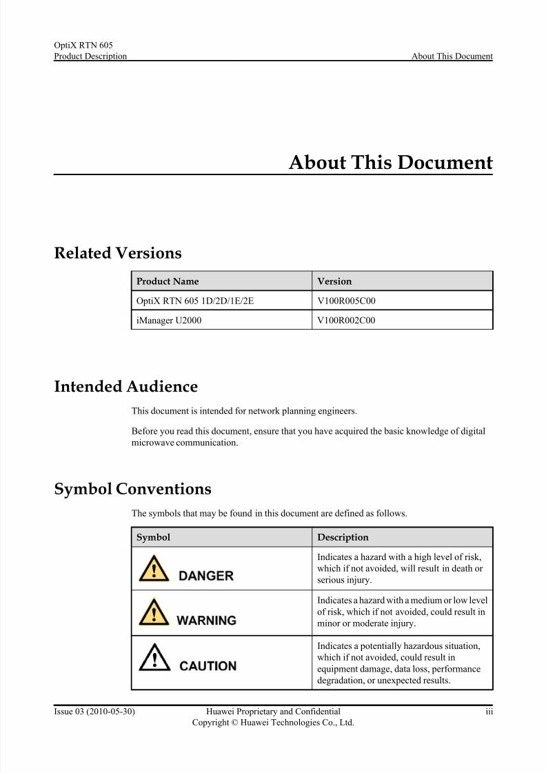
Symbol Conventions
The symbols that may be found in this document are defined as follows.
Symbol Description
Indicates a hazard with a high level of risk,
which if not avoided, will result in death or
serious injury.
Indicates a hazard with a medium or low level
of risk, which if not avoided, could result in
minor or moderate injury.
Indicates a potentially hazardous situation,
which if not avoided, could result in
equipment damage, data loss, performance
degradation, or unexpected results.
OptiX RTN 605
Product Description About This Document
Issue 03 (2010-05-30) Huawei Proprietary and Confidential
Copyright © Huawei Technologies Co., Ltd.
iii

7/22/2019 RTN 605 Product Description(V100R005C00_03)
http://slidepdf.com/reader/full/rtn-605-product-descriptionv100r005c0003 6/107
Symbol Description
Indicates a tip that may help you solve a
problem or save time.
Provides additional information to emphasizeor supplement important points of the main
text.
Update History
Updates between document issues are cumulative. Therefore, the latest document issue contains
all updates made in previous issues.
Updates in Issue 03 (2010-05-30) Based on Product Version V100R005C00
This document is the third release of the V100R005C00 version.
Compared with the second release, the updated contents are as follows:
Update Description
1.2 Components The descriptions of 13/18 GHz XMC-1 ODU
are added.6.1 RF Performance
Updates in Issue 02 (2010-03-30) Based on Product Version V100R005C00
This document is the second release of the V100R005C00 version.
Compared with the first release, the updated contents are as follows:
Update Description
1.2 Components The descriptions of XMC-1 ODU are added.
6.1.2 Frequency Band
6.1.4 Transceiver Performance
The whole document The information about the OptiX RTN 605
V100R003 is deleted.
Updates in Issue 01 (2009-12-30) Based on Product Version V100R005C00
This document is the first release of the V100R005C00 version.
About This Document
OptiX RTN 605
Product Description
iv Huawei Proprietary and Confidential
Copyright © Huawei Technologies Co., Ltd.
Issue 03 (2010-05-30)

7/22/2019 RTN 605 Product Description(V100R005C00_03)
http://slidepdf.com/reader/full/rtn-605-product-descriptionv100r005c0003 7/107
Contents
About This Document...................................................................................................................iii
1 Introduction.................................................................................................................................1-1
1.1 Positioning.......................................................................................................................................................1-2
1.2 Components.....................................................................................................................................................1-31.3 Configuration Model.......................................................................................................................................1-6
2 Functions and Features..............................................................................................................2-1
2.1 Microwave Type.............................................................................................................................................2-2
2.1.1 Mini PDH Radio.....................................................................................................................................2-2
2.1.2 Mini IP Radio.........................................................................................................................................2-2
2.2 RF Configuration Modes...................................................................................... ...........................................2-3
2.3 Interfaces.........................................................................................................................................................2-3
2.3.1 Service Interfaces...................................................................................................................................2-3
2.3.2 Management and Auxiliary Interfaces...................................................................................................2-4
2.4 Automatic Transmit Power Control................................................................................................................2-5
2.5 Ethernet Processing Capability.......................................................................................................................2-5
2.6 Protection Ca pability.......................................................................................................................................2-6
2.7 Network Management.....................................................................................................................................2-6
2.8 Easy Installation..............................................................................................................................................2-6
2.9 Easy Maintenance...........................................................................................................................................2-7
3 Product Architecture..................................................................................................................3-1
3.1 System Ar chitecture........................................................................................................................................3-2
3.2 Hardware Architecture....................................................................................................................................3-3
3.2.1 IDU.................................................................................................................. .......................................3-3
3.2.2 ODU.......................................................................................................................................................3-5
3.3 Software Architecture.....................................................................................................................................3-7
3.3.1 NMS Software............................................................................................................. ...........................3-7
3.3.2 IDU Software.........................................................................................................................................3-7
3.3.3 ODU Software............................................................................................................. ...........................3-8
3.4 Service Signal Processing Flow......................................................................................................................3-8
3.4.1 Mini PDH Radio....................................................................................................................................3-8
3.4.2 Mini IP Radio.......................................................................................................................................3-10
4 Networking..................................................................................................................................4-1
OptiX RTN 605
Product Description Contents
Issue 03 (2010-05-30) Huawei Proprietary and Confidential
Copyright © Huawei Technologies Co., Ltd.
v
7/22/2019 RTN 605 Product Description(V100R005C00_03)
http://slidepdf.com/reader/full/rtn-605-product-descriptionv100r005c0003 8/107
4.1 Mini PDH Radio..............................................................................................................................................4-2
4.2 Mini IP Radio..................................................................................................................................................4-3
5 Network Management System................................................................................................5-1
5.1 Network Management Solution...................................................................................................................... 5-25.2 Web LCT.........................................................................................................................................................5-2
5.3 U2000..............................................................................................................................................................5-3
6 Technical Specifications...........................................................................................................6-1
6.1 RF Perfor mance...............................................................................................................................................6-2
6.1.1 Radio Working Modes...........................................................................................................................6-2
6.1.2 Frequency Band......................................................................................................................................6-3
6.1.3 Receiver Sensitivity................................................................................................................................6-6
6.1.4 Transceiver Performance........................................................................................................................6-8
6.1.5 IF Performance.....................................................................................................................................6-116.1.6 Baseband Signal Processing Performance of the Modem....................................................................6-12
6.2 Equipment Reliability...................................................................................................................................6-12
6.2.1 Com ponent Reliability................................................................................................... ......................6-12
6.2.2 Link Reliability....................................................................................................................................6-13
6.3 Interface Performance...................................................................................................................................6-13
6.3.1 PDH Interface Performance.................................................................................................................6-13
6.3.2 Ethernet Interface Performance............................................................................................................6-14
6.3.3 Auxiliary Interface Performance..........................................................................................................6-15
6.4 Jitter Performance.........................................................................................................................................6-16
6.5 Integrated System Performance....................................................................................................................6-16
7 Standards Compliance..............................................................................................................7-1
7.1 ITU-R Standards............................................................................................................................................. 7-2
7.2 ETSI Standar ds................................................................................................................................................7-2
7.3 Relevant IEC Standards.................................................................................................................................. 7-3
7.4 ITU-T Standards..............................................................................................................................................7-4
7.5 IETF Standar ds................................................................................................................................................7-5
7.6 IEEE Standar ds............................................................................................................................................... 7-5
7.7 Environmental Standards................................................................................................................................ 7-6
A Glossary.....................................................................................................................................A-1
A.1 0-9..................................................................................................................................................................A-2
A.2 A-E................................................................................................................................................................A-2
A.3 F-J................................................................................................................................................................A-11
A.4 K-O..............................................................................................................................................................A-16
A.5 P-T...............................................................................................................................................................A-22
A.6 U-Z..............................................................................................................................................................A-30
Contents
OptiX RTN 605
Product Description
vi Huawei Proprietary and Confidential
Copyright © Huawei Technologies Co., Ltd.
Issue 03 (2010-05-30)

7/22/2019 RTN 605 Product Description(V100R005C00_03)
http://slidepdf.com/reader/full/rtn-605-product-descriptionv100r005c0003 9/107
Figures
Figure 1-1 Mini PDH radio tail access solution provided by the OptiX RTN 605..............................................1-2
Figure 1-2 Mini IP radio tail access solution.......................................................................................................1-3
Figure 1-3 IDU 605 (in the case of the IDU 605 2E)...........................................................................................1-4
Figure 1-4 Direct mounting .................................................................................................................................1-6
Figure 1-5 Separate mounting..............................................................................................................................1-6
Figure 2-1 Mini PDH radio..................................................................................................................................2-2
Figure 2-2 Mini IP Radio.....................................................................................................................................2-3
Figure 3-1 System architecture.............................................................................................................................3-2
Figure 3-2 Logic board configuration for the IDU 605 .......................................................................................3-4
Figure 3-3 Block diagram of the ODU.................................................................................................................3-6
Figure 3-4 Software architecture of the OptiX RTN 605.....................................................................................3-7
Figure 3-5 Signal processing flow........................................................................................................................3-8
Figure 3-6 Service signal processing flow.........................................................................................................3-10
Figure 4-1 Mini PDH radio tail access solution (independently).........................................................................4-2Figure 4-2 Mini PDH radio tail access solution (together with other OptiX RTN NEs).....................................4-2
Figure 4-3 Mini IP radio tail access solution.......................................................................................................4-3
Figure 5-1 NM solution of a transport network...................................................................................................5-2
OptiX RTN 605
Product Description Figures
Issue 03 (2010-05-30) Huawei Proprietary and Confidential
Copyright © Huawei Technologies Co., Ltd.
vii

7/22/2019 RTN 605 Product Description(V100R005C00_03)
http://slidepdf.com/reader/full/rtn-605-product-descriptionv100r005c0003 10/107
7/22/2019 RTN 605 Product Description(V100R005C00_03)
http://slidepdf.com/reader/full/rtn-605-product-descriptionv100r005c0003 11/107
Tables
Table 1-1 Intr oduction to the IDU 605.................................................................................................................1-3
Table 1-2 RT N 600 ODUs supported by the OptiX RTN 605.............................................................................1-5
Table 1-3 RT N XMC ODUs supported by the OptiX RTN 605..........................................................................1-5
Table 1-4 Configuration model of the OptiX RTN 605.......................................................................................1-7
Table 2-1 RF configuration modes.......................................................................................................................2-3
Table 2-2 Ser vice interfaces.................................................................................................................................2-4
Table 2-3 Management and auxiliary interfaces.................................................................................................. 2-4
Table 2-4 Auxiliary services or paths transmitted by each microwave interface.................................................2-5
Table 2-5 Ethernet service processing capability.................................................................................................2-5
Table 3-1 Functional units....................................................................................................................................3-2
Table 3-2 List of the logic boards on the IDU 605...............................................................................................3-4
Table 3-3 Signal processing flow (transmit direction).........................................................................................3-8
Table 3-4 Signal processing flow (receive direction)...........................................................................................3-9
Table 3-5 Signal processing flow (transmit direction) ......................................................................................3-10Table 3-6 Signal processing flow (receive direction) ........................................................................................3-11
Table 6-1 Working modes of the Mini PDH radio ..............................................................................................6-2
Table 6-2 Working modes of the Mini IP radio .................................................................................................. 6-3
Table 6-3 Frequency Band (SP ODU)..................................................................................................................6-4
Table 6-4 Frequency band (SPA ODU)............................................................................................................... 6-4
Table 6-5 Frequency band (LP ODU)..................................................................................................................6-5
Table 6-6 Frequency band (LPA ODU)...............................................................................................................6-5
Table 6-7 Frequency band (XMC-1 ODU).......................................................................................................... 6-5
Table 6-8 Ty pical values of the receiver sensitivity of the Mini radio (i)............................................................6-6
Table 6-9 Ty pical values of the receiver sensitivity of the Mini radio (ii)...........................................................6-7
Table 6-10 Tr ansceiver Performance (SP ODU)..................................................................................................6-8
Table 6-11 Tr ansceiver performance (SPA ODU)...............................................................................................6-8
Table 6-12 Tr ansceiver performance (LP ODU)..................................................................................................6-9
Table 6-13 Tr ansceiver performance (LPA ODU).............................................................................................6-10
Table 6-14 Tr ansceiver performance (XMC-1 ODU)........................................................................................6-10
Table 6-15 IF performance.................................................................................................................................6-11
Table 6-16 Baseband signal processing performance of the modem.................................................................6-12
Table 6-17 Component reliability.......................................................................................................................6-12
Table 6-18 Link reliability per hop.....................................................................................................................6-13
OptiX RTN 605
Product Description Tables
Issue 03 (2010-05-30) Huawei Proprietary and Confidential
Copyright © Huawei Technologies Co., Ltd.
ix
7/22/2019 RTN 605 Product Description(V100R005C00_03)
http://slidepdf.com/reader/full/rtn-605-product-descriptionv100r005c0003 12/107
Table 6-19 E1 interface performance.................................................................................................................6-14
Table 6-20 10/100/1000BASE-T(X) interface performance..............................................................................6-14
Table 6-21 10/100BASE-T(X) interface performance.......................................................................................6-14
Table 6-22 Orderwire interface performance.....................................................................................................6-15
Table 6-23 Synchronous data interface performance.........................................................................................6-15
Table 6-24 Asynchronous data interface performance.......................................................................................6-16
Table 6-25 Jitter performance.............................................................................................................................6-16
Table 6-26 Dimensions.......................................................................................................................................6-16
Table 6-27 Typical weight..................................................................................................................................6-17
Table 6-28 Typical power consumption.............................................................................................................6-17
Table 6-29 Power supply....................................................................................................................................6-17
Table 6-30 Environment.....................................................................................................................................6-18
Table 7-1 ITU-R standards...................................................................................................................................7-2
Table 7-2 ETSI standards.....................................................................................................................................7-3
Table 7-3 Relevant IEC standards........................................................................................................................7-4
Table 7-4 ITU-T standard.....................................................................................................................................7-4
Table 7-5 IETF standards.....................................................................................................................................7-5
Table 7-6 IEEE standards.....................................................................................................................................7-5
Table 7-7 Environmental standards......................................................................................................................7-6
Tables
OptiX RTN 605
Product Description
x Huawei Proprietary and Confidential
Copyright © Huawei Technologies Co., Ltd.
Issue 03 (2010-05-30)
7/22/2019 RTN 605 Product Description(V100R005C00_03)
http://slidepdf.com/reader/full/rtn-605-product-descriptionv100r005c0003 13/107
1 Introduction
About This Chapter
The OptiX R TN 605 is one of the series products of the OptiX RTN 600 radio transmission
system.
The OptiX R TN 600 V100R005 radio transmission system product series are classified into the
OptiX RTN 620 and the OptiX RTN 605. The OptiX RTN 620 and the OptiX RTN 605 can use
the same type of ODUs.
l The OptiX RTN 620 is a set of TDM/Hybrid integrated radio equipment. It adopts the 2U-
high IDU (namely, IDU 620), supports one to four microwave directions, and provides
networking radio solutions.l The OptiX RTN 605 is a set of Mini radio equipment. It adopts the 1U-high IDU (namely,
IDU 605), supports one microwave direction, and provides radio tail access solutions.
This manual describes the OptiX RTN 605 only. For the description of the OptiX RTN 620, see
the corresponding OptiX RTN 620 Product Description.
1.1 Positioning
The OptiX RTN 605 is a split radio transmission system developed by Huawei. It can provide
a tail radio access solution for the mobile communication network or private networks.
1.2 Components
The OptiX RTN 605 is of a split structure, consisting of the IDU 605 and the ODU. Each ODU
is connected to the IDU 605 through an IF cable.
1.3 Configuration Model
The OptiX RTN 605 forms different configuration models by flexibly configuring different types
of IDU 605s and ODUs to meet the requirements of different microwave application scenarios.
OptiX RTN 605
Product Description 1 Introduction
Issue 03 (2010-05-30) Huawei Proprietary and Confidential
Copyright © Huawei Technologies Co., Ltd.
1-1

7/22/2019 RTN 605 Product Description(V100R005C00_03)
http://slidepdf.com/reader/full/rtn-605-product-descriptionv100r005c0003 14/107
1.1 Positioning
The OptiX RTN 605 is a split radio transmission system developed by Huawei. It can provide
a tail radio access solution for the mobile communication network or private networks.
The OptiX RTN 605 provides several types of service interfaces and features flexible
configuration and easy installation. In addition, the OptiX RTN 605 can provide a Mini PDH
radio or Mini IP radio tail access solution according to the network requirements.
NOTE
The Mini IP radio solution supports the simultaneous transmission of the E1 services and low capacity
Ethernet services, but does not support the adaptive modulation (AM) function.
l Mini PDH radio tail access solution
Figure 1-1 Mini PDH radio tail access solution provided by the OptiX RTN 605
OptiX RTN 605 BTS BSC
E1
E1E1
E1
E1
Radio transmission
network
E1
E1
l Mini IP radio tail access solution
1 Introduction
OptiX RTN 605
Product Description
1-2 Huawei Proprietary and Confidential
Copyright © Huawei Technologies Co., Ltd.
Issue 03 (2010-05-30)
7/22/2019 RTN 605 Product Description(V100R005C00_03)
http://slidepdf.com/reader/full/rtn-605-product-descriptionv100r005c0003 15/107
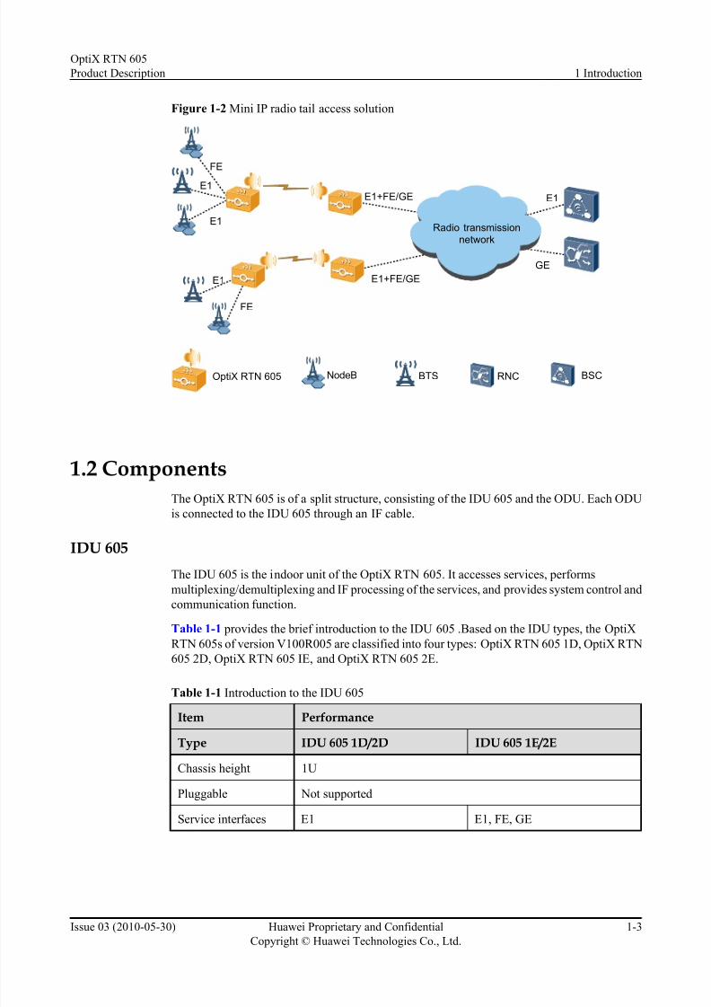
Figure 1-2 Mini IP radio tail access solution
OptiX RTN 605 BTSNodeB BSCRNC
FE
E1
E1
E1
GE
E1
FE
E1+FE/GE
E1+FE/GE
Radio transmissionnetwork
1.2 Components
The OptiX RTN 605 is of a split structure, consisting of the IDU 605 and the ODU. Each ODU
is connected to the IDU 605 through an IF cable.
IDU 605
The IDU 605 is the indoor unit of the OptiX RTN 605. It accesses services, performs
multiplexing/demultiplexing and IF processing of the services, and provides system control and
communication function.
Table 1-1 provides the brief introduction to the IDU 605 .Based on the IDU types, the OptiX
RTN 605s of version V100R005 are classified into four types: OptiX RTN 605 1D, OptiX RTN
605 2D, OptiX RTN 605 IE, and OptiX RTN 605 2E.
Table 1-1 Introduction to the IDU 605
Item Performance
Type IDU 605 1D/2D IDU 605 1E/2E
Chassis height 1U
Pluggable Not supported
Service interfaces E1 E1, FE, GE
OptiX RTN 605
Product Description 1 Introduction
Issue 03 (2010-05-30) Huawei Proprietary and Confidential
Copyright © Huawei Technologies Co., Ltd.
1-3

7/22/2019 RTN 605 Product Description(V100R005C00_03)
http://slidepdf.com/reader/full/rtn-605-product-descriptionv100r005c0003 16/107
Item Performance
Type IDU 605 1D/2D IDU 605 1E/2E
Ethernet processing
capability
Not supported l Supports the VLAN and
QinQ.
l Supports Layer 2 switching,
supports EPLAN and
EVPLAN.
l Supports EVPL.
l Supports QoS (including
CAR and CoS) functions,
traffic classification based on
port, four priority queues, and
SP or WRR queue scheduling
l
Supports Ethernet OAM based on IEEE 802.1 ag and
IEEE 802.3 ah
l Supports the LAG.
l Supports the Synchronous
Ethernet.
Radio type Mini PDH radio Mini IP radio
Number of microwave
directions
1
RF configurationmode
1+0 non-protection (IDU 605 1D/1E)1+1 protection (IDU 605 2D/2E)
Figure 1-3 IDU 605 (in the case of the IDU 605 2E)
ODU
The ODU is the outdoor unit of the OptiX RTN 605. It performs frequency conversion and
amplification of signals.
The OptiX RTN 605 provide a complete ODU solution. OptiX RTN 605 supports the RTN 600
ODU. Generally, the OptiX RTN 605 is configured with the low capacity for PDH ODU. If
required in certain special scenarios, the OptiX RTN 605 can also be configured with the standard power ODU.
1 Introduction
OptiX RTN 605
Product Description
1-4 Huawei Proprietary and Confidential
Copyright © Huawei Technologies Co., Ltd.
Issue 03 (2010-05-30)

7/22/2019 RTN 605 Product Description(V100R005C00_03)
http://slidepdf.com/reader/full/rtn-605-product-descriptionv100r005c0003 17/107
NOTE
Unlike the other frequency bands that use 14 MHz, 28 MHz, or 56 MHz channel spacing, the 18 GHz
frequency band uses 13.75 MHz, 27.5 MHz, or 55 MHz channel spacing correspondingly.
Table 1-2 RTN 600 ODUs supported by the OptiX RTN 605
Item Description
Low Capacity for PDH ODU Standard Power ODU
ODU type LP and LPA SP and SPA
Frequency band 7/8/11/13/15/18/23 GHz (LP ODU)
7/8/11/13/15/18/23/26/32/38 GHz
(LPA ODU)
7/8/11/13/15/18/23/26/38 GHz (SP
ODU)
6/7/8/11/13/15/18/23 GHz (SPA
ODU)
Microwavemodulation
mode
QPSK/16QAM QPSK/16QAM/32QAM/64QAM/128QAM/256QAM (SP ODU)
QPSK/16QAM/32QAM/64QAM/
128QAM (SPA ODU)
Channel spacing 3.5/7/14/28 MHz 3.5/7/14/28 MHz
Table 1-3 RTN XMC ODUs supported by the OptiX RTN 605
Item Description
Low Capacity for PDH ODU
ODU type XMC-1
Frequency band 7/8/13/15/18/23 GHz
Microwave modulation mode QPSK/16QAM
Channel spacing 3.5/7/14/28 MHz
There are two methods of mounting the ODU and the antenna: direct mounting and separatemounting.
NOTE
The OptiX RTN 605 provides an entire frequency band antenna solution, and supports the single-polarized
antenna and dual-polarized antenna with a diameter of 0.3 m to 3.7 m and the corresponding feeder system.
l The direct mounting method is normally adopted when a small-diameter and single-
polarized antenna is used. In this situation, if one ODU is configured for one antenna, the
ODU is directly mounted at the back of the antenna. If two ODUs are configured for one
antenna, an RF signal combiner/splitter (hereinafter referred to as a hybrid coupler) must
be mounted to connect the ODUs to the antenna. Figure 1-4 shows the direct mounting.
OptiX RTN 605
Product Description 1 Introduction
Issue 03 (2010-05-30) Huawei Proprietary and Confidential
Copyright © Huawei Technologies Co., Ltd.
1-5

7/22/2019 RTN 605 Product Description(V100R005C00_03)
http://slidepdf.com/reader/full/rtn-605-product-descriptionv100r005c0003 18/107
Figure 1-4 Direct mounting
l The separate mounting method is adopted when a double-polarized antenna or a large-
diameter and single-polarized antenna is used. Figure 1-5 shows the separate mounting.
In this situation, a hybrid coupler can be mounted to enable two ODUs to share one feed
boom.
Figure 1-5 Separate mounting
1.3 Configuration Model
The OptiX RTN 605 forms different configuration models by flexibly configuring different types
of IDU 605s and ODUs to meet the requirements of different microwave application scenarios.
1 Introduction
OptiX RTN 605
Product Description
1-6 Huawei Proprietary and Confidential
Copyright © Huawei Technologies Co., Ltd.
Issue 03 (2010-05-30)
7/22/2019 RTN 605 Product Description(V100R005C00_03)
http://slidepdf.com/reader/full/rtn-605-product-descriptionv100r005c0003 19/107
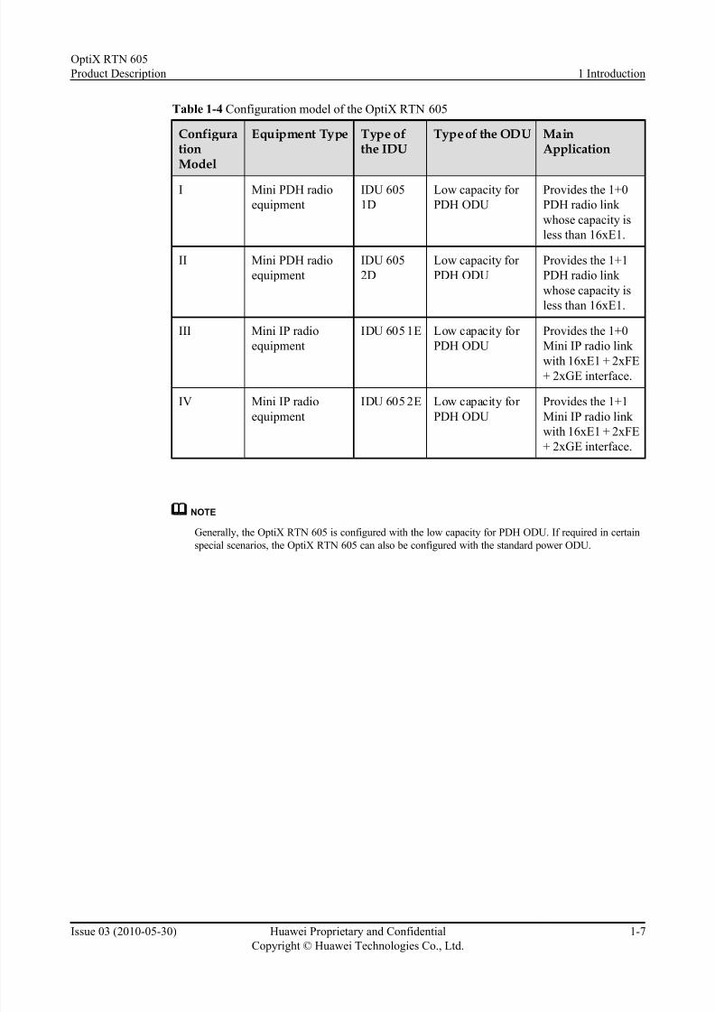
Table 1-4 Configuration model of the OptiX RTN 605
ConfigurationModel
Equipment Type Type ofthe IDU
Type of the ODU MainApplication
I Mini PDH radio
equipment
IDU 605
1D
Low capacity for
PDH ODU
Provides the 1+0
PDH radio link
whose capacity is
less than 16xE1.
II Mini PDH radio
equipment
IDU 605
2D
Low capacity for
PDH ODU
Provides the 1+1
PDH radio link
whose capacity is
less than 16xE1.
III Mini IP radio
equipment
IDU 605 1E Low capacity for
PDH ODU
Provides the 1+0
Mini IP radio link
with 16xE1 + 2xFE
+ 2xGE interface.
IV Mini IP radio
equipment
IDU 605 2E Low capacity for
PDH ODU
Provides the 1+1
Mini IP radio link
with 16xE1 + 2xFE
+ 2xGE interface.
NOTE
Generally, the OptiX RTN 605 is configured with the low capacity for PDH ODU. If required in certainspecial scenarios, the OptiX RTN 605 can also be configured with the standard power ODU.
OptiX RTN 605
Product Description 1 Introduction
Issue 03 (2010-05-30) Huawei Proprietary and Confidential
Copyright © Huawei Technologies Co., Ltd.
1-7

7/22/2019 RTN 605 Product Description(V100R005C00_03)
http://slidepdf.com/reader/full/rtn-605-product-descriptionv100r005c0003 20/107
7/22/2019 RTN 605 Product Description(V100R005C00_03)
http://slidepdf.com/reader/full/rtn-605-product-descriptionv100r005c0003 21/107
2 Functions and Features
About This Chapter
The OptiX R TN 605 provides various f unctions and features to ensure the quality and efficiency
of service transmission.
2.1 Microwave Type
The OptiX R TN 605 supports different microwave types according to the configuration model.
2.2 RF Configuration Modes
The OptiX R TN 605 supports the 1+0 non-protection configuration and the 1+1 protection
configuration.
2.3 Interfaces
The OptiX R TN 605 has various interface types.
2.4 Automatic Transmit Power Control
The automatic transmit power control (ATPC) function enables the output power of the
transmitter to automatically trace the level f luctuation at the receive end. This technology reduces
the interference with neighboring systems and residual BER rate.
2.5 Ethernet Processing Capability
The 1E/2E provides powerful Ethernet service processing capability.
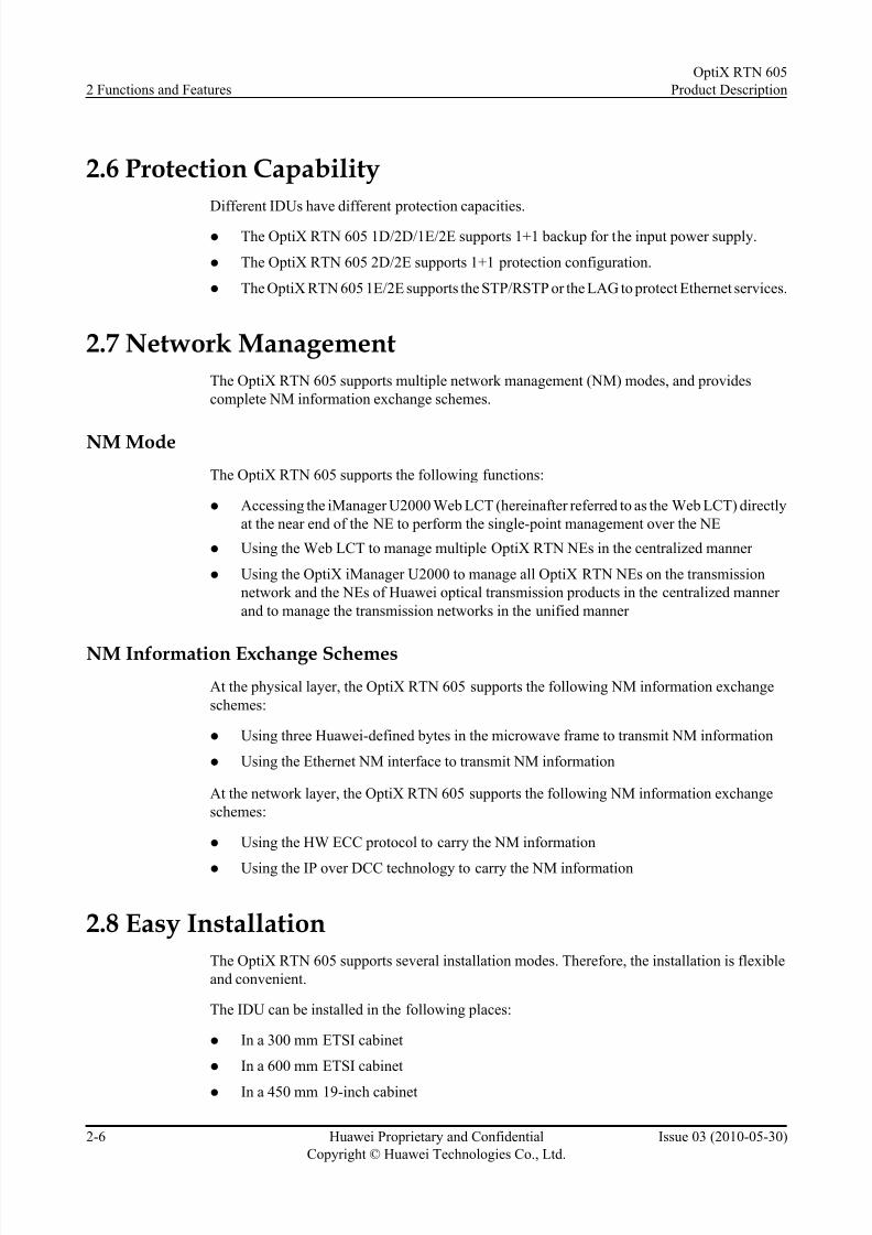
2.6 Protection Capability
Different IDUs have different protection capacities.
2.7 Network Management
The OptiX RTN 605 supports multiple network management (NM) modes, and provides
complete NM information exchange schemes.
2.8 Easy Installation
The OptiX RTN 605 supports several installation modes. Therefore, the installation is flexible
and convenient.
2.9 Easy Maintenance
The OptiX RTN 605 provides several maintenance features. Therefore, it can effectively reduce
the cost of equipment maintenance.
OptiX RTN 605
Product Description 2 Functions and Features
Issue 03 (2010-05-30) Huawei Proprietary and Confidential
Copyright © Huawei Technologies Co., Ltd.
2-1

7/22/2019 RTN 605 Product Description(V100R005C00_03)
http://slidepdf.com/reader/full/rtn-605-product-descriptionv100r005c0003 22/107
2.1 Microwave Type
The OptiX RTN 605 supports different microwave types according to the configuration model.
2.1.1 Mini PDH Radio
The Mini PDH radio refers to the radio system that transmits the E1 services of low or middle
capacity. .
2.1.2 Mini IP Radio
The Mini IP radio refers to the radio system that can transmit both Native E1 services and Native
Ethernet services of low or middle capacity.
2.1.1 Mini PDH Radio
The Mini PDH radio refers to the radio system that transmits the E1 services of low or middle
capacity. .
NOTE
The OptiX RTN 605 1D/2D supports PDH radio.
The Mini PDH radio equipment transmits the incoming E1 services to the microwave port and
then transmit the signals over the radio link.
Figure 2-1 Mini PDH radio
ODUE1
IDUMini PDH radio
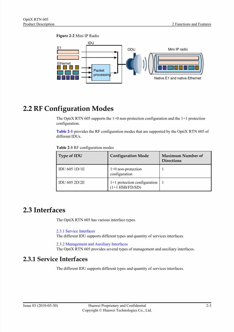
2.1.2 Mini IP Radio
The Mini IP radio refers to the radio system that can transmit both Native E1 services and Native
Ethernet services of low or middle capacity.
NOTE
The OptiX RTN 605 1E/2E supports Mini IP radio.
E1 services are accessed and transmitted directly to the microwave interface. Ethernet services
are accessed, processed on the packet processing plane, and then transmitted to the microwave
interface. E1 services and Ethernet services are mapped into microwave frames and then
transmits the microwave frames.
2 Functions and Features
OptiX RTN 605
Product Description
2-2 Huawei Proprietary and Confidential
Copyright © Huawei Technologies Co., Ltd.
Issue 03 (2010-05-30)
7/22/2019 RTN 605 Product Description(V100R005C00_03)
http://slidepdf.com/reader/full/rtn-605-product-descriptionv100r005c0003 23/107
Figure 2-2 Mini IP Radio
ODU
Ethernet
E1
IDU
Packet
processing
Mini IP radio
Native E1 and native Ethernet
2.2 RF Configuration Modes
The OptiX R TN 605 supports the 1+0 non-protection configuration and the 1+1 protection
configuration.
Table 2-1 pr ovides the RF configuration modes that are supported by the OptiX RTN 605 of
different IDUs.
Table 2-1 RF configuration modes
Type of IDU Configuration Mode Maximum Number ofDirections
IDU 605 1D/1E 1+0 non-protection
configuration
1
IDU 605 2D/2E 1+1 protection configuration
(1+1 HSB/FD/SD)
1
2.3 Interfaces
The OptiX RTN 605 has various interface types.
2.3.1 Service InterfacesThe different IDU supports different types and quantity of services interfaces.
2.3.2 Management and Auxiliary Interfaces
The OptiX RTN 605 provides several types of management and auxiliary interfaces.
2.3.1 Service Interfaces
The different IDU supports different types and quantity of services interfaces.
OptiX RTN 605
Product Description 2 Functions and Features
Issue 03 (2010-05-30) Huawei Proprietary and Confidential
Copyright © Huawei Technologies Co., Ltd.
2-3

7/22/2019 RTN 605 Product Description(V100R005C00_03)
http://slidepdf.com/reader/full/rtn-605-product-descriptionv100r005c0003 24/107
Table 2-2 Service interfaces
Type of the IDU Service interface Quantity
IDU 605 1D/2D 75/120-ohm E1 interface 16
IDU 605 1E/2E 75/120-ohm E1 interface 16
FE electrical interface:
10/100BASE-T(X)
2
GE electrical interface:
10/100/1000BASE-T(X)
2
NOTE
The impedance of E1 interfaces on the OptiX RTN 605 can be set by using NMS.
2.3.2 Management and Auxiliary Interfaces
The OptiX RTN 605 provides several types of management and auxiliary interfaces.
Table 2-3 Management and auxiliary interfaces
Interface Specifications Quantity
Management interface 10/100BASE-T(X) Ethernet
NM interface
1
NM serial port 1
10/100BASE-T(X) NE
cascade interface
1
Auxiliary interface Orderwire interface 1
RS-232 asynchronous data
interface
1
64 kbit/s synchronous data
interface
1
Alarm interface Alarm input/output interface Three inputs + one output
NOTE
The synchronous data interface can also transparently transmit one orderwire overhead byte. This interface,
however, can realize only one function at one time.
Auxiliary services and NM messages are transmitted by overhead bytes over a radio link. For
details, refer to Table 2-4.
2 Functions and Features
OptiX RTN 605
Product Description
2-4 Huawei Proprietary and Confidential
Copyright © Huawei Technologies Co., Ltd.
Issue 03 (2010-05-30)

7/22/2019 RTN 605 Product Description(V100R005C00_03)
http://slidepdf.com/reader/full/rtn-605-product-descriptionv100r005c0003 25/107
Table 2-4 Auxiliary services or paths transmitted by each microwave interface
Service/Path Type Quantity Rate
Asynchronous data service 1 ≤ 19.2 kbit/s
Synchronous data service 1 64 kbit/s
Orderwire phone service 1 64 kbit/s
DCC channel 1 192 kbit/s
2.4 Automatic Transmit Power ControlThe automatic transmit power control (ATPC) function enables the output power of the
transmitter to automatically trace the level fluctuation at the receive end. This technology reducesthe interference with neighboring systems and residual BER rate.
2.5 Ethernet Processing CapabilityThe 1E/2E provides powerful Ethernet service processing capability.
Table 2-5 Ethernet service processing capability
Feature 1E/2E
Interfaces 2xFE + 2xGE/FE
Format of service frames Ethernet II, IEEE 802.3, IEEE 802.1q/p
Type of Ethernet services EPLAN (802.1d), VLAN-based EVPLAN (802.1q), QinQ-
based EVPL
VLAN Supports the VLAN and QinQ. Supports addition and
deletion of VLAN tags that comply with IEEE 802.1q.
CAR Supported
CoS Supported
Queue scheduling scheme Supports the strict priority (SP) or weighted round robin
(WRR).
Flow control IEEE 802.3x
Ethernet performance
monitoring
Supports the RMON performance monitoring that complies
with IETF RFC 2819.
ETH-OAM IEEE 802.1ag, IEEE 802.3ah
LAG (Link aggregation group) Supported
Synchronous Ethernet Supported
OptiX RTN 605
Product Description 2 Functions and Features
Issue 03 (2010-05-30) Huawei Proprietary and Confidential
Copyright © Huawei Technologies Co., Ltd.
2-5
7/22/2019 RTN 605 Product Description(V100R005C00_03)
http://slidepdf.com/reader/full/rtn-605-product-descriptionv100r005c0003 26/107

7/22/2019 RTN 605 Product Description(V100R005C00_03)
http://slidepdf.com/reader/full/rtn-605-product-descriptionv100r005c0003 27/107
l In a 600 mm 19-inch cabinet
l In an open cabinet
l On a wall
l
On a desk
The ODU can be installed in two modes: direct mounting and separate mounting.
2.9 Easy Maintenance
The OptiX RTN 605 provides several maintenance features. Therefore, it can effectively reduce
the cost of equipment maintenance.
l The boards are installed in a chassis, which facilitates the maintenance.
l Adopts the natural heat dissipation method. The equipment does not have the fan system
and thus has lower noise.
l Supports various loopback functions of service ports and IF ports.
l Embeds a test system. You can perform the pseudo-random binary sequence (PRBS) test
of an E1 or IF port when no special test tools are available.
l Supports the monitoring and the graphic display of key radio transmission performance
specifications such as the microwave transmit power and the received signal strength
indicator (RSSI).
l Supports the RMON performance events and ETH-OAM.
l Supports remote loading of the NE software and data by using the NMS.
l Supports the hot patch loading function. Thus, you can upgrade the software that is running
without interrupting services.l Support the software version rollback function. When a software upgrade fails, the original
services of the system can be restored.
OptiX RTN 605
Product Description 2 Functions and Features
Issue 03 (2010-05-30) Huawei Proprietary and Confidential
Copyright © Huawei Technologies Co., Ltd.
2-7

7/22/2019 RTN 605 Product Description(V100R005C00_03)
http://slidepdf.com/reader/full/rtn-605-product-descriptionv100r005c0003 28/107

7/22/2019 RTN 605 Product Description(V100R005C00_03)
http://slidepdf.com/reader/full/rtn-605-product-descriptionv100r005c0003 29/107
3 Product Architecture
About This Chapter
This topic describes the system structure, hardware structure, and software structure of the
product, and the process for processing service signals.
3.1 System Architecture
The OptiX R TN 605 consists of a series of functional units, including the service interface unit,
IF unit, control unit, clock unit, auxiliary interface unit, power unit, and ODU.
3.2 Hardware Architecture
The OptiX R TN 605 is of a split structure, consisting of the IDU and the ODU. Each ODU is
connected to the IDU through a IF cable. The IF cable transmits IF service signals and the O&M
signals of the ODU. In addition, the IF cable supplies -48 V power supply to the ODU.
3.3 Software Architecture
The software package of the OptiX RTN 605 contains the NMS software, IDU software, and
ODU software.
3.4 Service Signal Processing Flow
The processing flows is different for transmitting the Mini PDH radio signals or transmitting
the Mini IP radio signals.
OptiX RTN 605
Product Description 3 Product Architecture
Issue 03 (2010-05-30) Huawei Proprietary and Confidential
Copyright © Huawei Technologies Co., Ltd.
3-1

7/22/2019 RTN 605 Product Description(V100R005C00_03)
http://slidepdf.com/reader/full/rtn-605-product-descriptionv100r005c0003 30/107
3.1 System Architecture
The OptiX RTN 605 consists of a series of functional units, including the service interface unit,IF unit, control unit, clock unit, auxiliary interface unit, power unit, and ODU.
Figure 3-1 System architecture
Service
interface
unit
IF unit
ODU
Power
unit
Control
unit
Auxiliaryinterface
unit
E1
-48V/-60V DC
RF signal
IF signal
Synchronous/asynchronous data
Orderwire data
External alarm data
NM data
IDU
Control bus
Antenna
Service
signal
Overhead
signal
FE/GE
Clock
unit
NOTE
The IDU 605 1D/2D does not support accessing FE/GE signals.
The clock unit of the IDU 605 1E/2E can trace the clock of the radio link and the clock of the synchronous
Ethernet signals.
The clock unit of the IDU 605 does not process the clock of E1 signals.
Table 3-1 Functional units
Functional Unit Function Description
Service interface unit l Accesses E1 signals.
l Accesses FE/GE signals.
IF unit l Maps service signals to microwave frame signals and demaps
microwave frame signals to service signals.
l Performs conversion between microwave frame signals and IF
analog signals.
l Provides the operations and maintenance (O&M) channel
between the IDU and the ODU.
l Provides the forward error correction (FEC) function.
l Processes overheads.
3 Product Architecture
OptiX RTN 605
Product Description
3-2 Huawei Proprietary and Confidential
Copyright © Huawei Technologies Co., Ltd.
Issue 03 (2010-05-30)

7/22/2019 RTN 605 Product Description(V100R005C00_03)
http://slidepdf.com/reader/full/rtn-605-product-descriptionv100r005c0003 31/107
Functional Unit Function Description
Control unit l Functions for system communications and control.
l Functions for system configuration and management.
l Collects alarms and monitors performance.
Clock unit l Detects and traces the clock of the microwave link and the clock
of the synchronous Ethernet signals
l Provides the clock for the microwave link and synchronous
Ethernet signals
Auxiliary interface
unit
l Provides the orderwire interface.
l Provides the synchronous/asynchronous data interface.
l Provides the external alarm input/output interface.
Power unit l Accesses -48 V/-60 V DC power.l Provides DC power for the IDU.
l Provides -48 V power for the ODU.
ODU l Converses between the IF analog signal and the RF signal.
l Provides the O&M channel that is connected to the IDU.
3.2 Hardware Architecture
The OptiX RTN 605 is of a split structure, consisting of the IDU and the ODU. Each ODU is
connected to the IDU through a IF cable. The IF cable transmits IF service signals and the O&M
signals of the ODU. In addition, the IF cable supplies -48 V power supply to the ODU.
3.2.1 IDU
The IDU 605 is composed of one system board and one power board. Each functional unit on
the physical boards of the IDU 605 corresponds to a logical board and is allocated with a logical
slot. Hence, the NMS can manage the functional units as independent objects.
3.2.2 ODU
The ODU is an integrated system and is of various types. The structures and working principles
of various types of ODUs are the same.
3.2.1 IDU
The IDU 605 is composed of one system board and one power board. Each functional unit on
the physical boards of the IDU 605 corresponds to a logical board and is allocated with a logical
slot. Hence, the NMS can manage the functional units as independent objects.
OptiX RTN 605
Product Description 3 Product Architecture
Issue 03 (2010-05-30) Huawei Proprietary and Confidential
Copyright © Huawei Technologies Co., Ltd.
3-3

7/22/2019 RTN 605 Product Description(V100R005C00_03)
http://slidepdf.com/reader/full/rtn-605-product-descriptionv100r005c0003 32/107
Figure 3-2 Logic board configuration for the IDU 605
IDU 605 1E
PH1EOWSCCPW48A/PW48B
Slot 1 Slot 2 Slot 3 Slot 4
IF0
Slot 8
EM4T
Slot 5
IDU 605 2E
PH1EOWSCCPW48A/PW48B
Slot 1 Slot 2 Slot 3 Slot 4
IF0IF0
Slot 8
EM4T
Slot 5 Slot 7
IDU 605 1D
PH1EOWSCC
PW48A/
PW48B
Slot 1 Slot 2 Slot 3 Slot 4
IF0
Slot 8
IDU 605 2D
PH1EOWSCCPW48A/
PW48B
Slot 1 Slot 2 Slot 3 Slot 4
IF0IF0
Slot 8Slot 7
Table 3-2 List of the logic boards on the IDU 605
LogicalBoardName
Full Name Logical Slot Description
PW48A -48 V power board Slot 1 Provides two inputs of -48 V DC
power.PW48B
SCC System control and
communication board
Slot 2 Provides the NMS interface.
EOW Orderwire board Slot 3 Provides the synchronous/
asynchronous data interface and
orderwire interface.
PH1 16xE1 tributary board Slot 4 Provides 16 75-ohm/120-ohm E1
interfaces. The interface
impedance can be set by using the
software.
3 Product Architecture
OptiX RTN 605
Product Description
3-4 Huawei Proprietary and Confidential
Copyright © Huawei Technologies Co., Ltd.
Issue 03 (2010-05-30)

7/22/2019 RTN 605 Product Description(V100R005C00_03)
http://slidepdf.com/reader/full/rtn-605-product-descriptionv100r005c0003 33/107
LogicalBoardName
Full Name Logical Slot Description
EM4T 4-port RJ-45 Fast
Ethernet/Gigabit
Ethernet switching
processing board
Slot 5 l Provides two FE electrical
interfaces and two GE
electrical interface (the GE
electrical interface is
compatible with the FE
electrical interfaces).
l Processes Ethernet transparent
transmission services and
Layer 2 switching services.
IF0 IF board Slot 8 (IDU
605 1D/1E)
Slot 7/8 (IDU605 2E)
l Provides one IF interface. The
logical slot number of the
ODU that is connected to theIF board is 10 plus the slot
number of the IF board.
l Supports the E1-based
microwave frame format.
Support the Mini PDH radio in
the IDU 605 1D/2D and
support the Mini IP radio in the
IDU 605 1E/2E.
NOTE
The PW48A or PW48B is the logical board that corresponds to the physical board with the same name.
The PH1, EM4T, IF0, SCC, and EOW are the logical boards mapped by the system control board. Different
types of IDU 605 have different system control boards and thus have different logical boards.
3.2.2 ODU
The ODU is an integrated system and is of various types. The structures and working principles
of various types of ODUs are the same.
OptiX RTN 605
Product Description 3 Product Architecture
Issue 03 (2010-05-30) Huawei Proprietary and Confidential
Copyright © Huawei Technologies Co., Ltd.
3-5

7/22/2019 RTN 605 Product Description(V100R005C00_03)
http://slidepdf.com/reader/full/rtn-605-product-descriptionv100r005c0003 34/107
Block Diagram
Figure 3-3 Block diagram of the ODU
Antenna port
CTRL
Tx IF
Rx IF
Cable port
PWR
Up-conversionMultiplexer
O&M
uplink
O&M
downlink
DC
Down-conversion
AMP
LNA
Synthesizers
Duplexer
Rx RF
Tx RF
Signal Processing in the Transmit Direction
The multiplexer splits the signal coming from the IF cable into a 350 MHz IF signal, an O&M
uplink signal, and a -48 V DC power signal.
In the transmit direction, the IF signal is processed as follows:
1. Through the up-conversion, filtering, and amplification, the IF signal is converted into theRF signal and then sent to the AMP amplifier unit.
2. The AMP amplifies the RF signal (the output power of the signal can be controlled by the
IDU software).
3. After the amplification, the RF signal is sent to the antenna through the diplexer.
The O&M uplink signal is a 5.5 MHz ASK-modulated signal and is demodulated in the CTRL
control unit.
The -48 V DC power signal is sent to the PWR power unit where the secondary power supply
of a different voltage is generated and provided to the modules of the ODU.
Signal Processing in the Receive Direction
In the diplexer, the receive RF signal is separated from the antenna signal. The RF signal is
amplified in the low noise amplifier (LNA). Through the down-conversion, filtering, and
amplification, the RF signal is converted into the 140 MHz IF signal and then sent to the
multiplexer.
The O&M downlink signal is modulated under the ASK scheme in the CTRL unit. The 10 MHz
signal is generated through the modulation and sent to the multiplexer. The CTRL unit also
detects the receive power through the RSSI detection circuit and provides the RSSI interface.
The IF signal and the O&M downlink signal are combined in the multiplexer and then sent tothe IDU through the IF cable.
3 Product Architecture
OptiX RTN 605
Product Description
3-6 Huawei Proprietary and Confidential
Copyright © Huawei Technologies Co., Ltd.
Issue 03 (2010-05-30)

7/22/2019 RTN 605 Product Description(V100R005C00_03)
http://slidepdf.com/reader/full/rtn-605-product-descriptionv100r005c0003 35/107
3.3 Software Architecture
The software package of the OptiX RTN 605 contains the NMS software, IDU software, and
ODU software.
For the software architecture of the OptiX RTN 605, see Figure 3-4. The NMS software
communicates with the IDU software through the Qx interface. The Qx interface uses the OptiX
private management protocol.
Figure 3-4 Software architecture of the OptiX RTN 605
NMS software
Qx interface
IDU software ODU software
3.3.1 NMS Software
Huawei provides a transport network management solution that meets the requirements of the
telecommunication management network (TMN) for managing all the OptiX RTN 605 products
and the optical transmission products of the OptiX series on the network.
3.3.2 IDU Software
The IDU software consists of the NE software and the board software.
3.3.3 ODU Software
The ODU sof tware manages and controls the running status of the ODU. The ODU software
controls the r unning status of the ODU according to the parameter delivered by the IDU software.
In addition, the running status of the ODU is reported to the IDU software.
3.3.1 NMS Software
Huawei provides a transport network management solution that meets the requirements of the
telecommunication management network (TMN) for managing all the OptiX RTN 605 products
and the optical transmission products of the OptiX series on the network.
For details, refer to section 5.1 Network Management Solution.
3.3.2 IDU Software
The IDU software consists of the NE software and the board software.
The NE software manages, monitors, and controls the running status of the IDU. Through the
NE software, the NMS communicates with the boards, and controls and manages the NE. In
addition, the NE software communicates with the ODU software to manage and control the
operation of the ODU.
The board software manages and controls the running status of all boards of the IDU except the
SCC board. Currently, the IDU does not have the independent board software . The board
software of other boards, in the form of modules, is integrated into the NE software and runs inthe CPU of the SCC board.
OptiX RTN 605
Product Description 3 Product Architecture
Issue 03 (2010-05-30) Huawei Proprietary and Confidential
Copyright © Huawei Technologies Co., Ltd.
3-7
7/22/2019 RTN 605 Product Description(V100R005C00_03)
http://slidepdf.com/reader/full/rtn-605-product-descriptionv100r005c0003 36/107
3.3.3 ODU Software
The ODU software manages and controls the running status of the ODU. The ODU software
controls the running status of the ODU according to the parameter delivered by the IDU software.
In addition, the running status of the ODU is reported to the IDU software.
3.4 Service Signal Processing Flow
The processing flows is different for transmitting the Mini PDH radio signals or transmitting
the Mini IP radio signals.
3.4.1 Mini PDH Radio
This topic describes the Mini PDH radio signal processing flow of the OptiX RTN 605 1D/2D
through the example of E1 signals.
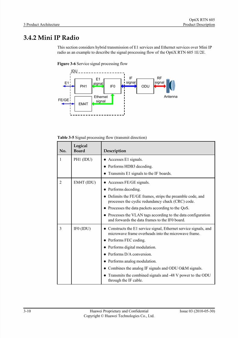
3.4.2 Mini IP Radio
This section considers hybrid transmission of E1 services and Ethernet services over Mini IP
radio as an example to describe the signal processing flow of the OptiX RTN 605 1E/2E.
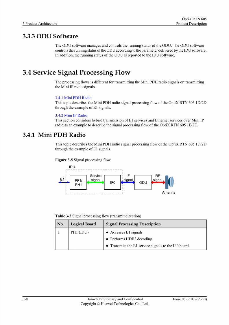
3.4.1 Mini PDH Radio
This topic describes the Mini PDH radio signal processing flow of the OptiX RTN 605 1D/2D
through the example of E1 signals.
Figure 3-5 Signal processing flow
PF1/PH1
IF0 ODU
RFsignal
IFsignal
IDU
Servicesignal
Antenna
E1
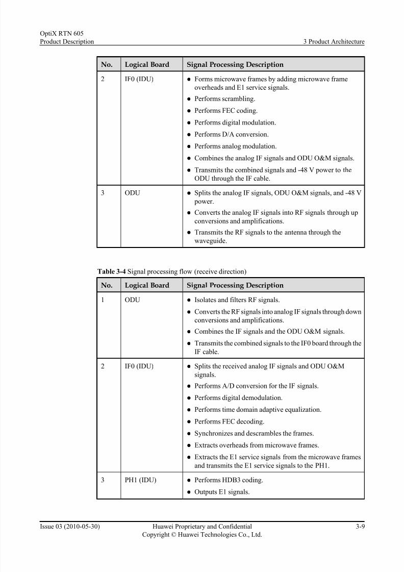
Table 3-3 Signal processing flow (transmit direction)
No. Logical Board Signal Processing Description
1 PH1 (IDU) l Accesses E1 signals.
l Performs HDB3 decoding.
l Transmits the E1 service signals to the IF0 board.
3 Product Architecture
OptiX RTN 605
Product Description
3-8 Huawei Proprietary and Confidential
Copyright © Huawei Technologies Co., Ltd.
Issue 03 (2010-05-30)
7/22/2019 RTN 605 Product Description(V100R005C00_03)
http://slidepdf.com/reader/full/rtn-605-product-descriptionv100r005c0003 37/107
No. Logical Board Signal Processing Description
2 IF0 (IDU) l Forms microwave frames by adding microwave frame
overheads and E1 service signals.
l Performs scrambling.l Performs FEC coding.
l Performs digital modulation.
l Performs D/A conversion.
l Performs analog modulation.
l Combines the analog IF signals and ODU O&M signals.
l Transmits the combined signals and -48 V power to the
ODU through the IF cable.
3 ODU l Splits the analog IF signals, ODU O&M signals, and -48 V
power.
l Converts the analog IF signals into RF signals through up
conversions and amplifications.
l Transmits the RF signals to the antenna through the
waveguide.
Table 3-4 Signal processing flow (receive direction)
No. Logical Board Signal Processing Description
1 ODU l Isolates and filters RF signals.
l Converts the RF signals into analog IF signals through down
conversions and amplifications.
l Combines the IF signals and the ODU O&M signals.
l Transmits the combined signals to the IF0 board through the
IF cable.
2 IF0 (IDU) l Splits the received analog IF signals and ODU O&M
signals.
l Performs A/D conversion for the IF signals.
l
Performs digital demodulation.l Performs time domain adaptive equalization.
l Performs FEC decoding.
l Synchronizes and descrambles the frames.
l Extracts overheads from microwave frames.
l Extracts the E1 service signals from the microwave frames
and transmits the E1 service signals to the PH1.
3 PH1 (IDU) l Performs HDB3 coding.
l Outputs E1 signals.
OptiX RTN 605
Product Description 3 Product Architecture
Issue 03 (2010-05-30) Huawei Proprietary and Confidential
Copyright © Huawei Technologies Co., Ltd.
3-9
7/22/2019 RTN 605 Product Description(V100R005C00_03)
http://slidepdf.com/reader/full/rtn-605-product-descriptionv100r005c0003 38/107
3.4.2 Mini IP Radio
This section considers hybrid transmission of E1 services and Ethernet services over Mini IP
radio as an example to describe the signal processing flow of the OptiX RTN 605 1E/2E.
Figure 3-6 Service signal processing flow
PH1 IF0 ODU
RFsignal
IFsignal
IDU
E1
signal
Antenna
E1
EM4TFE/GE
Ethernet
signal
Table 3-5 Signal processing flow (transmit direction)
No.LogicalBoard Description
1 PH1 (IDU) l Accesses E1 signals.
l Performs HDB3 decoding.
l Transmits E1 signals to the IF boards.
2 EM4T (IDU) l Accesses FE/GE signals.
l Performs decoding.
l Delimits the FE/GE frames, strips the preamble code, and
processes the cyclic redundancy check (CRC) code.
l Processes the data packets according to the QoS.
l Processes the VLAN tags according to the data configuration
and forwards the data frames to the IF0 board.
3 IF0 (IDU) l Constructs the E1 service signal, Ethernet service signals, and
microwave frame overheads into the microwave frame.
l Performs FEC coding.
l Performs digital modulation.
l Performs D/A conversion.
l Performs analog modulation.
l Combines the analog IF signals and ODU O&M signals.
l Transmits the combined signals and -48 V power to the ODU
through the IF cable.
3 Product Architecture
OptiX RTN 605
Product Description
3-10 Huawei Proprietary and Confidential
Copyright © Huawei Technologies Co., Ltd.
Issue 03 (2010-05-30)

7/22/2019 RTN 605 Product Description(V100R005C00_03)
http://slidepdf.com/reader/full/rtn-605-product-descriptionv100r005c0003 39/107

7/22/2019 RTN 605 Product Description(V100R005C00_03)
http://slidepdf.com/reader/full/rtn-605-product-descriptionv100r005c0003 40/107

7/22/2019 RTN 605 Product Description(V100R005C00_03)
http://slidepdf.com/reader/full/rtn-605-product-descriptionv100r005c0003 41/107
4 Networking
About This Chapter
The OptiX RTN 605 supports multiple types of networking modes to meet different requirements
of customers.
4.1 Mini PDH Radio
The OptiX RTN 605 1D/2D can provide the Mini PDH radio access link independently or
together with other OptiX RTN NEs.
4.2 Mini IP Radio
The OptiX RTN 605 1E/2E can transmit the E1 services and Ethernet services through Mini IP
radio , supports independent tail access in point-to-point mode.
OptiX RTN 605
Product Description 4 Networking
Issue 03 (2010-05-30) Huawei Proprietary and Confidential
Copyright © Huawei Technologies Co., Ltd.
4-1

7/22/2019 RTN 605 Product Description(V100R005C00_03)
http://slidepdf.com/reader/full/rtn-605-product-descriptionv100r005c0003 42/107

7/22/2019 RTN 605 Product Description(V100R005C00_03)
http://slidepdf.com/reader/full/rtn-605-product-descriptionv100r005c0003 43/107
4.2 Mini IP Radio
The OptiX RTN 605 1E/2E can transmit the E1 services and Ethernet services through Mini IP
radio , supports independent tail access in point-to-point mode.
NOTE
The OptiX RTN 605 1E/2E dose not support provide Mini IP radio tail link together with other OptiX RTN
NEs.
In the tail access solution through Mini IP radio shown in Figure 4-3, an ordinary link adopts
the OptiX RTN 605 1E to realize 1+0 non-protection configuration, and an important link adopts
the OptiX RTN 605 2E to realize 1+1 protection configuration.
Figure 4-3 Mini IP radio tail access solution
E1+FE/GE
Radio transmissionnetwork
Tail link
NodeB
E1
E1
BTS
BTS
FE
NodeB
FE BSC
E1
GE
RNCE1+FE/GE
OptiX RTN 605
Product Description 4 Networking
Issue 03 (2010-05-30) Huawei Proprietary and Confidential
Copyright © Huawei Technologies Co., Ltd.
4-3

7/22/2019 RTN 605 Product Description(V100R005C00_03)
http://slidepdf.com/reader/full/rtn-605-product-descriptionv100r005c0003 44/107

7/22/2019 RTN 605 Product Description(V100R005C00_03)
http://slidepdf.com/reader/full/rtn-605-product-descriptionv100r005c0003 45/107
5 Network Management System
About This Chapter
This topic describes the network management system solution and multiple types of NMS
software required by this solution.
5.1 Network Management Solution
Huawei provides a complete transport network management solution compliant with TMN for
different function domains and customers in telecommunication networks.
5.2 Web LCT
The Web LCT is a local maintenance terminal. A user can access the Web LCT server by using
the IE explor er to manage a single NE. The Web LCT provides the following NE-levelmanagement functions: NE management, alarm management, performance management,
configuration management, communication management, and security management.
5.3 U2000
The U2000 is a network-level network management system. A user can access the U2000 server
through a U2000 client to manage Huawei transport network in the unified manner. The U2000
can provide not only the NE-level management function, but also the network-level management
function.
OptiX RTN 605
Product Description 5 Network Management System
Issue 03 (2010-05-30) Huawei Proprietary and Confidential
Copyright © Huawei Technologies Co., Ltd.
5-1

7/22/2019 RTN 605 Product Description(V100R005C00_03)
http://slidepdf.com/reader/full/rtn-605-product-descriptionv100r005c0003 46/107
5.1 Network Management Solution
Huawei provides a complete transport network management solution compliant with TMN for
different function domains and customers in telecommunication networks.
The NM solutions include the following:
l iManager U2000 Web LCT Local Craft Terminal
l iManager U2000 Unified Network Management System
Figure 5-1 NM solution of a transport network
Network level
NMS
Local craft
terminal
iManager U2000
iManager Web LCT
5.2 Web LCT
The Web LCT is a local maintenance terminal. A user can access the Web LCT server by using
the IE explorer to manage a single NE. The Web LCT provides the following NE-levelmanagement functions: NE management, alarm management, performance management,
configuration management, communication management, and security management.
NOTE
The Web LCT supports the end-to-end management over one microwave hop. Thus, it can manage the opposite
NE in the NE Explorer of the local end of the microwave link.
NE Management
l Searching for NEs
l Adding/Deleting NEs
l Logging in to/Logging out of NEs
l Managing NE time
Alarm Management
l Setting alarm monitoring strategies
l Viewing alarms
l Deleting alarms
Performance Management
l Setting performance monitoring strategies
5 Network Management System
OptiX RTN 605
Product Description
5-2 Huawei Proprietary and Confidential
Copyright © Huawei Technologies Co., Ltd.
Issue 03 (2010-05-30)
7/22/2019 RTN 605 Product Description(V100R005C00_03)
http://slidepdf.com/reader/full/rtn-605-product-descriptionv100r005c0003 47/107
l Viewing performance events
l Resetting performance registers
Configuration Management
l Configuring basic NE information
l Configuring radio links
l Configuring protection schemes
l Configuring interfaces
l Configuring services
l Configuring clock
Communication Management
l Managing communication parameters
l Managing the DCC
l Managing the HW ECC protocol
l Managing the IP protocol
l Configuring the OSI protocol
Security Management
l Managing NE users
l Managing NE user groups
l Managing LCT access control
l Managing online users
l Managing NE security parameters
l Managing NE security logs
l Managing NM users
l Managing NM logs
5.3 U2000
The U2000 is a network-level network management system. A user can access the U2000 server
through a U2000 client to manage Huawei transport network in the unified manner. The U2000
can provide not only the NE-level management function, but also the network-level management
function.
NE-Level Management Functions
l NE Management
l NE-level alarm management
l NE-level performance management
l NE-level configuration management
OptiX RTN 605
Product Description 5 Network Management System
Issue 03 (2010-05-30) Huawei Proprietary and Confidential
Copyright © Huawei Technologies Co., Ltd.
5-3
7/22/2019 RTN 605 Product Description(V100R005C00_03)
http://slidepdf.com/reader/full/rtn-605-product-descriptionv100r005c0003 48/107

7/22/2019 RTN 605 Product Description(V100R005C00_03)
http://slidepdf.com/reader/full/rtn-605-product-descriptionv100r005c0003 49/107
6 Technical Specifications
About This Chapter
This topic describes the technical specifications of the OptiX RTN 605.
6.1 RF Performance
The RF performance includes the technical specifications related to the microwave radio system.
6.2 Equipment Reliability
Equipment reliability includes the IDU reliability, the ODU reliability and the link reliability.
6.3 Interface Performance
Interface perf ormance consists of the performance of service interfaces and the performance of auxiliary interfaces.
6.4 Jitter Perf ormance
The output jitter performance at the PDH interface complies with relevant ITU-T
recommendations.
6.5 Integrated System Performance
Integrated system performance includes the dimensions, weight, power supply, power
consumption, EMC, lightning protection, safety, and environment.
OptiX RTN 605
Product Description 6 Technical Specifications
Issue 03 (2010-05-30) Huawei Proprietary and Confidential
Copyright © Huawei Technologies Co., Ltd.
6-1

7/22/2019 RTN 605 Product Description(V100R005C00_03)
http://slidepdf.com/reader/full/rtn-605-product-descriptionv100r005c0003 50/107
6.1 RF Performance
The RF performance includes the technical specifications related to the microwave radio system.
6.1.1 Radio Working Modes
This topic describes the microwave radio working modes supported by the OptiX RTN 605.
6.1.2 Frequency Band
The ODUs of the different series and different types support different operating frequency bands.
6.1.3 Receiver Sensitivity
The receiver sensitivity reflects the anti-fading capability of the microwave equipment.
6.1.4 Transceiver Performance
The performance of the transceiver includes the nominal maximum/minimum transmit power,
nominal maximum receive power, and frequency stability.
6.1.5 IF Performance
The IF performance includes the performance of the IF signal and the performance of the ODU
O&M signal.
6.1.6 Baseband Signal Processing Performance of the Modem
The baseband signal processing performance of the modem indicates the FEC coding scheme
and the performance of the baseband time domain adaptive equalizer.
6.1.1 Radio Working Modes
This topic describes the microwave radio working modes supported by the OptiX RTN 605.
Working Modes of the Mini PDH Radio
Table 6-1 Working modes of the Mini PDH radio
Mode No. Air InterfaceService Capacity(Mbit/s)
MaximumNumber of E1s
ChannelSpacing (MHz)
Modulation Mode
19 10 5 3.5 16QAM
16 10 5 7 QPSK
20 20 10 7 16QAM
17 20 10 14 (13.75) QPSK
6 32 16 14 (13.75) 16QAM
5 32 16 28 (27.5) QPSK
6 Technical Specifications
OptiX RTN 605
Product Description
6-2 Huawei Proprietary and Confidential
Copyright © Huawei Technologies Co., Ltd.
Issue 03 (2010-05-30)
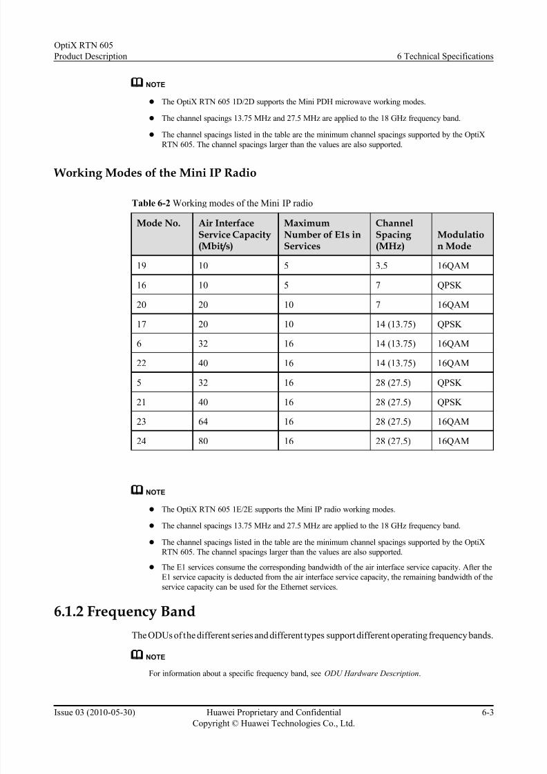
7/22/2019 RTN 605 Product Description(V100R005C00_03)
http://slidepdf.com/reader/full/rtn-605-product-descriptionv100r005c0003 51/107
NOTE
l The OptiX RTN 605 1D/2D supports the Mini PDH microwave working modes.
l The channel spacings 13.75 MHz and 27.5 MHz are applied to the 18 GHz frequency band.
l The channel spacings listed in the table are the minimum channel spacings supported by the OptiXRTN 605. The channel spacings larger than the values are also supported.
Working Modes of the Mini IP Radio
Table 6-2 Working modes of the Mini IP radio
Mode No. Air InterfaceService Capacity(Mbit/s)
MaximumNumber of E1s inServices
ChannelSpacing (MHz)
Modulation Mode
19 10 5 3.5 16QAM
16 10 5 7 QPSK
20 20 10 7 16QAM
17 20 10 14 (13.75) QPSK
6 32 16 14 (13.75) 16QAM
22 40 16 14 (13.75) 16QAM
5 32 16 28 (27.5) QPSK
21 40 16 28 (27.5) QPSK
23 64 16 28 (27.5) 16QAM
24 80 16 28 (27.5) 16QAM
NOTE
l The OptiX RTN 605 1E/2E supports the Mini IP radio working modes.
l The channel spacings 13.75 MHz and 27.5 MHz are applied to the 18 GHz frequency band.
l The channel spacings listed in the table are the minimum channel spacings supported by the OptiXRTN 605. The channel spacings larger than the values are also supported.
l The E1 services consume the corresponding bandwidth of the air interface service capacity. After the
E1 service capacity is deducted from the air interface service capacity, the remaining bandwidth of the
service capacity can be used for the Ethernet services.
6.1.2 Frequency Band
The ODUs of the different series and different types support different operating frequency bands.
NOTE
For information about a specific frequency band, see ODU Hardware Description.
OptiX RTN 605
Product Description 6 Technical Specifications
Issue 03 (2010-05-30) Huawei Proprietary and Confidential
Copyright © Huawei Technologies Co., Ltd.
6-3

7/22/2019 RTN 605 Product Description(V100R005C00_03)
http://slidepdf.com/reader/full/rtn-605-product-descriptionv100r005c0003 52/107

7/22/2019 RTN 605 Product Description(V100R005C00_03)
http://slidepdf.com/reader/full/rtn-605-product-descriptionv100r005c0003 53/107

7/22/2019 RTN 605 Product Description(V100R005C00_03)
http://slidepdf.com/reader/full/rtn-605-product-descriptionv100r005c0003 54/107
FrequencyBand
Frequency Range (GHz) T/R Spacing (MHz)
13 GHz 12.751-13.248 266
15 GHz 14.400-15.358 315/322, 420, 475, 490, 640, 644, 728
18 GHz 17.685-19.710 1010/1008, 1092.5, 1560
23 GHz 21.200-23.618 1008, 1200, 1232
6.1.3 Receiver Sensitivity
The receiver sensitivity reflects the anti-fading capability of the microwave equipment.
NOTE
For a guaranteed value, remove 3 dB from the typical value.
NOTE
l The OptiX RTN 605 1D/2D supports the working modes that are numbered 5, 6, 16, 17, 19, and 20.
l The OptiX RTN 605 1E/2E supports the working modes that are numbered 5, 6, 16, 17, 19, 20, 21, 22,
23, and 24.
Table 6-8 Typical values of the receiver sensitivity of the Mini radio (i)
Item Performance
Working mode
5 6 16 17 19 20
Channelspacing
28 MHz 14 MHz 7 MHz 14 MHz 3.5 MHz 7 MHz
ModulationMode
QPSK 16QAM QPSK QPSK 16QAM 16QAM
RSL@ BER=10-6 (dBm)
@6 GHz -85.5 -81.5 -90.0 -87.0 -88.5 -84.5
@7 GHz -85.5 -81.5 -90.0 -87.0 -88.5 -84.5
@8 GHz -85.5 -81.5 -90.0 -87.0 -88.5 -84.5
@11 GHz -85.0 -81.0 -89.5 -86.5 -88.0 -84.0
@13 GHz -85.0 -81.0 -89.5 -86.5 -88.0 -84.0
@15 GHz -85.0 -81.0 -89.5 -86.5 -88.0 -84.0
@18 GHz -85.0 -81.0 -89.5 -86.5 -88.0 -84.0
@23 GHz -84.5 -80.5 -89.0 -86.0 -87.5 -83.5
6 Technical Specifications
OptiX RTN 605
Product Description
6-6 Huawei Proprietary and Confidential
Copyright © Huawei Technologies Co., Ltd.
Issue 03 (2010-05-30)

7/22/2019 RTN 605 Product Description(V100R005C00_03)
http://slidepdf.com/reader/full/rtn-605-product-descriptionv100r005c0003 55/107
Item Performance
Working mode
5 6 16 17 19 20
Channelspacing
28 MHz 14 MHz 7 MHz 14 MHz 3.5 MHz 7 MHz
ModulationMode
QPSK 16QAM QPSK QPSK 16QAM 16QAM
@26 GHz -84.0 -80.0 -88.5 -85.5 -87.0 -83.0
@32 GHz -83.0 -79.0 -87.5 -84.5 -86.0 -82.0
@38 GHz -82.5 -78.5 -87.0 -84.0 -85.5 -81.5
Table 6-9 Typical values of the receiver sensitivity of the Mini radio (ii)
Item Performance
Working mode
21 22 23 24
Channelspacing
28 MHz 14 MHz 28 MHz 28 MHz
ModulationMode
QPSK 16QAM 16QAM 16QAM
RSL@ BER=10-6 (dBm)
@6 GHz -84.5 -80.5 -78.5 -77.5
@7 GHz -84.5 -80.5 -78.5 -77.5
@8 GHz -84.5 -80.5 -78.5 -77.5
@11 GHz -84.0 -80.0 -78.0 -77.0
@13 GHz -84.0 -80.0 -78.0 -77.0
@15 GHz -84.0 -80.0 -78.0 -77.0
@18 GHz -84.0 -80.0 -78.0 -77.0
@23 GHz -83.5 -79.5 -77.5 -76.5
@26 GHz -83.0 -79.0 -77.0 -76.0
@32 GHz -82.0 -78.0 -76.0 -75.0
@38 GHz -81.5 -77.5 -75.5 -74.5
OptiX RTN 605
Product Description 6 Technical Specifications
Issue 03 (2010-05-30) Huawei Proprietary and Confidential
Copyright © Huawei Technologies Co., Ltd.
6-7

7/22/2019 RTN 605 Product Description(V100R005C00_03)
http://slidepdf.com/reader/full/rtn-605-product-descriptionv100r005c0003 56/107
6.1.4 Transceiver Performance
The performance of the transceiver includes the nominal maximum/minimum transmit power,
nominal maximum receive power, and frequency stability.
Transceiver Performance (Standard Power ODU)
Table 6-10 Transceiver Performance (SP ODU)
Item Performance
QPSK 16QAM/ 32QAM
64QAM/ 128QAM
256QAM
Nominal maximum transmit power (dBm)
@7 GHz 27 22.5 18.5 16.5
@8 GHz 27 22.5 18.5 16.5
@11 GHz 26 21.5 17.5 15.5
@13 GHz 26 21.5 17.5 15.5
@15 GHz 26 21.5 17.5 15.5
@18 GHz 25.5 21.5 17.5 15.5
@23 GHz 24 20.5 16.5 14.5
@26 GHz 23.5 19.5 15.5 13.5
@38 GHz 22 17.5 13.5 11.5
Nominal
minimum
transmit power
(dBm)
-6
Nominal
maximum
receive power
(dBm)
-20 -25
Frequency
stability (ppm)
±5
Table 6-11 Transceiver performance (SPA ODU)
Item Performance
QPSK 16QAM/32QAM 64QAM/128QAM
Nominal maximum transmit power (dBm)
6 Technical Specifications
OptiX RTN 605
Product Description
6-8 Huawei Proprietary and Confidential
Copyright © Huawei Technologies Co., Ltd.
Issue 03 (2010-05-30)

7/22/2019 RTN 605 Product Description(V100R005C00_03)
http://slidepdf.com/reader/full/rtn-605-product-descriptionv100r005c0003 57/107
Item Performance
QPSK 16QAM/32QAM 64QAM/128QAM
@6 GHz 26.5 24 23
@7 GHz 25.5 21.5 20
@8 GHz 25.5 21.5 20
@11 GHz 24.5 20.5 18
@13 GHz 24.5 20 18
@15 GHz 24.5 20 18
@18 GHz 22.5 19 17
@23 GHz 22.5 19 16
Nominal minimum
transmit power
(dBm)
0
Nominal maximum
receive power (dBm)
-20
Frequency stability
(ppm)
±5
Transceiver Performance (Low Capacity PDH ODU)
Table 6-12 Transceiver performance (LP ODU)
Item Performance
QPSK 16QAM
Nominal maximum transmit power (dBm)
@7 GHz 27 21
@8 GHz 27 21
@11 GHz 25 19
@13 GHz 25 19
@15 GHz 23.5 17.5
@18 GHz 23 17
@23 GHz 23 17
Nominal minimum transmit
power (dBm)
0
OptiX RTN 605
Product Description 6 Technical Specifications
Issue 03 (2010-05-30) Huawei Proprietary and Confidential
Copyright © Huawei Technologies Co., Ltd.
6-9
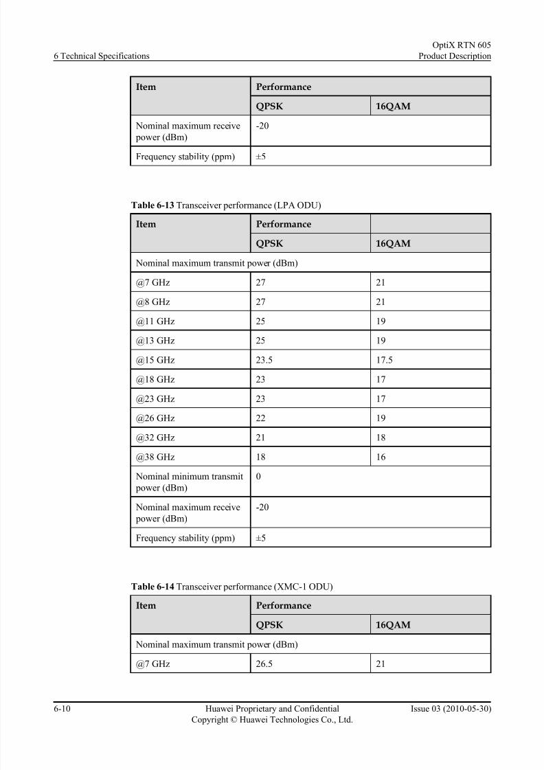
7/22/2019 RTN 605 Product Description(V100R005C00_03)
http://slidepdf.com/reader/full/rtn-605-product-descriptionv100r005c0003 58/107
Item Performance
QPSK 16QAM
Nominal maximum receive
power (dBm)
-20
Frequency stability (ppm) ±5
Table 6-13 Transceiver performance (LPA ODU)
Item Performance
QPSK 16QAM
Nominal maximum transmit power (dBm)
@7 GHz 27 21
@8 GHz 27 21
@11 GHz 25 19
@13 GHz 25 19
@15 GHz 23.5 17.5
@18 GHz 23 17
@23 GHz 23 17
@26 GHz 22 19
@32 GHz 21 18
@38 GHz 18 16
Nominal minimum transmit
power (dBm)
0
Nominal maximum receive
power (dBm)
-20
Frequency stability (ppm) ±5
Table 6-14 Transceiver performance (XMC-1 ODU)
Item Performance
QPSK 16QAM
Nominal maximum transmit power (dBm)
@7 GHz 26.5 21
6 Technical Specifications
OptiX RTN 605
Product Description
6-10 Huawei Proprietary and Confidential
Copyright © Huawei Technologies Co., Ltd.
Issue 03 (2010-05-30)
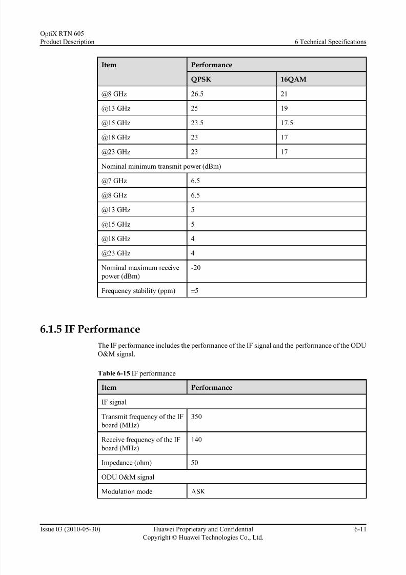
7/22/2019 RTN 605 Product Description(V100R005C00_03)
http://slidepdf.com/reader/full/rtn-605-product-descriptionv100r005c0003 59/107
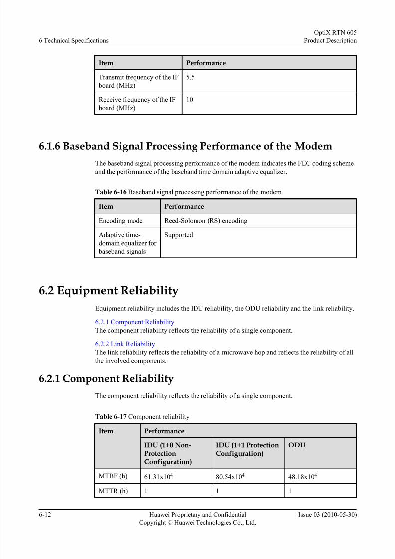
7/22/2019 RTN 605 Product Description(V100R005C00_03)
http://slidepdf.com/reader/full/rtn-605-product-descriptionv100r005c0003 60/107
Item Performance
Transmit frequency of the IF
board (MHz)
5.5
Receive frequency of the IF board (MHz)
10
6.1.6 Baseband Signal Processing Performance of the Modem
The baseband signal processing performance of the modem indicates the FEC coding scheme
and the performance of the baseband time domain adaptive equalizer.
Table 6-16 Baseband signal processing performance of the modem
Item Performance
Encoding mode Reed-Solomon (RS) encoding
Adaptive time-
domain equalizer for
baseband signals
Supported
6.2 Equipment ReliabilityEquipment reliability includes the IDU reliability, the ODU reliability and the link reliability.
6.2.1 Component Reliability
The component reliability reflects the reliability of a single component.
6.2.2 Link Reliability
The link reliability reflects the reliability of a microwave hop and reflects the reliability of all
the involved components.
6.2.1 Component Reliability
The component reliability reflects the reliability of a single component.
Table 6-17 Component reliability
Item Performance
IDU (1+0 Non-ProtectionConfiguration)
IDU (1+1 ProtectionConfiguration)
ODU
MTBF (h) 61.31x10⁴ 80.54x10⁴ 48.18x10⁴
MTTR (h) 1 1 1
6 Technical Specifications
OptiX RTN 605
Product Description
6-12 Huawei Proprietary and Confidential
Copyright © Huawei Technologies Co., Ltd.
Issue 03 (2010-05-30)

7/22/2019 RTN 605 Product Description(V100R005C00_03)
http://slidepdf.com/reader/full/rtn-605-product-descriptionv100r005c0003 61/107
Item Performance
IDU (1+0 Non-ProtectionConfiguration)
IDU (1+1 ProtectionConfiguration)
ODU
Availability 99.99984% 99.99988% 99.99979%
6.2.2 Link Reliability
The link reliability reflects the reliability of a microwave hop and reflects the reliability of all
the involved components.
Table 6-18 Link reliability per hop
Item Performance
1+0 Non-ProtectionConfiguration
1+1 Protection Configuration
MTBF (h) 13.49x10⁴ 34.50x10⁴
MTTR (h) 1 1
Availability 99.99926% 99.99971%
6.3 Interface Performance
Interface performance consists of the performance of service interfaces and the performance of
auxiliary interfaces.
6.3.1 PDH Interface Performance
The performance of the PDH interface is compliant with ITU-T G.703.
6.3.2 Ethernet Interface Performance
The performance of the Ethernet interface is compliant with IEEE 802.3.
6.3.3 Auxiliary Interface Performance
The performance of the auxiliary interfaces includes the performance of the order interface,
synchronous data interface, and asynchronous data interface.
6.3.1 PDH Interface Performance
The performance of the PDH interface is compliant with ITU-T G.703.
E1 Interface Performance
The performance of the E1 interface is compliant with ITU-T G.703. The following table provides the primary performance.
OptiX RTN 605
Product Description 6 Technical Specifications
Issue 03 (2010-05-30) Huawei Proprietary and Confidential
Copyright © Huawei Technologies Co., Ltd.
6-13

7/22/2019 RTN 605 Product Description(V100R005C00_03)
http://slidepdf.com/reader/full/rtn-605-product-descriptionv100r005c0003 62/107
Table 6-19 E1 interface performance
Item Performance
Nominal bit rate (kbit/s) 2048
Code pattern HDB3
Wire pair in each
transmission direction
One coaxial wire pair One symmetrical wire pair
Impedance (ohm) 75 120
6.3.2 Ethernet Interface Performance
The performance of the Ethernet interface is compliant with IEEE 802.3.
GE Electrical Interface Performance
The GE electrical interface is 10/100/1000BASE-T(X) interface and compliant with IEEE 802.3.
The GE electrical interface is compatible with FE electrical interfaces. The following table
provides the primary performance.
Table 6-20 10/100/1000BASE-T(X) interface performance
Item Performance
Nominal bit rate (Mbit/s) 10 (10BASE-T)
100 (100BASE-TX)
1000 (1000BASE-T)
Code pattern Manchester encoding signal (10BASE-T)
MLT-3 encoding signal (100BASE-TX)
4D-PAM5 encoding signal (1000BASE-T)
Interface type RJ-45
FE electrical Interface Performance
FE interfaces are 10/100BASE-T(X) interfaces and comply with IEEE 802.3. The following
table provides the primary performance.
Table 6-21 10/100BASE-T(X) interface performance
Item Performance
Nominal bit rate (Mbit/s) 10 (10BASE-T)
100 (100BASE-TX)
6 Technical Specifications
OptiX RTN 605
Product Description
6-14 Huawei Proprietary and Confidential
Copyright © Huawei Technologies Co., Ltd.
Issue 03 (2010-05-30)
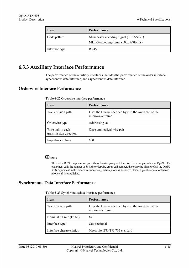
7/22/2019 RTN 605 Product Description(V100R005C00_03)
http://slidepdf.com/reader/full/rtn-605-product-descriptionv100r005c0003 63/107
Item Performance
Code pattern Manchester encoding signal (10BASE-T)
MLT-3 encoding signal (100BASE-TX)
Interface type RJ-45
6.3.3 Auxiliary Interface Performance
The performance of the auxiliary interfaces includes the performance of the order interface,
synchronous data interface, and asynchronous data interface.
Orderwire Interface Performance
Table 6-22 Orderwire interface performance
Item Performance
Transmission path Uses the Huawei-defined byte in the overhead of the
microwave frame.
Orderwire type Addressing call
Wire pair in each
transmission direction
One symmetrical wire pair
Impedance (ohm) 600
NOTE
The OptiX RTN equipment supports the orderwire group call function. For example, when an OptiX RTN
equipment calls the number of 888, the orderwire group call number, the orderwire phones of all the OptiX
RTN equipment in the orderwire subnet ring until a phone is answered. Then, a point-to-point orderwire
phone call is established.
Synchronous Data Interface Performance
Table 6-23 Synchronous data interface performance
Item Performance
Transmission path Uses the Huawei-defined byte in the overhead of the
microwave frame.
Nominal bit rate (kbit/s) 64
Interface type Codirectional
Interface characteristics Meets the ITU-T G.703 standard.
OptiX RTN 605
Product Description 6 Technical Specifications
Issue 03 (2010-05-30) Huawei Proprietary and Confidential
Copyright © Huawei Technologies Co., Ltd.
6-15

7/22/2019 RTN 605 Product Description(V100R005C00_03)
http://slidepdf.com/reader/full/rtn-605-product-descriptionv100r005c0003 64/107

7/22/2019 RTN 605 Product Description(V100R005C00_03)
http://slidepdf.com/reader/full/rtn-605-product-descriptionv100r005c0003 65/107
Weight and Power Consumption
Table 6-27 Typical weight
Component Typical WeightIDU < 2.7 kg
ODU < 4.6 kg
Table 6-28 Typical power consumption
No. Radio LinkForm
Configuration Typical PowerConsumption
(IDU+ODU)
1 Mini PDH radio
link
16xE1, 1+0 non-protection
(1xIDU 605 1D+1xLP ODU)
35.2W
2 16xE1, 1+1 HSB protection
(1xIDU 605 2D+2xLP ODU)
51.9W
3 Mini IP radio link 2xFE+2xGE+16xE1, 1+0 non-
protection
(1xIDU 605 1E+1xLP ODU)
38.6W
4 2xFE+2xGE+16xE1, 1+1 HSB
protection
(1xIDU 605 2E+2xLP ODU)
57.0W
Power Supply
Table 6-29 Power supply
Component Performance
IDU l Complies with ETSI EN300 132-2.
l Supports two -48 V/-60 V (-38.4 V to -72 V) DC power
inputs (mutual backup, load sharing).
ODU l Complies with ETSI EN300 132-2.
l The IDU provides one -48 V (-38.4 V to -72 V) DC power
input.
EMC
l Passes CE authentication.
OptiX RTN 605
Product Description 6 Technical Specifications
Issue 03 (2010-05-30) Huawei Proprietary and Confidential
Copyright © Huawei Technologies Co., Ltd.
6-17
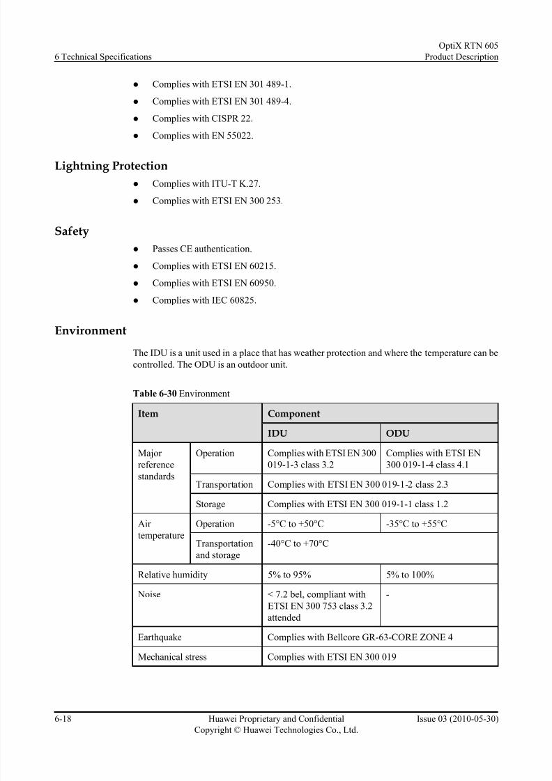
7/22/2019 RTN 605 Product Description(V100R005C00_03)
http://slidepdf.com/reader/full/rtn-605-product-descriptionv100r005c0003 66/107
7/22/2019 RTN 605 Product Description(V100R005C00_03)
http://slidepdf.com/reader/full/rtn-605-product-descriptionv100r005c0003 67/107
7 Standards Compliance
About This Chapter
7.1 ITU-R Standards
The OptiX R TN 605 complies with the ITU-R standards designed for microwave equipment.
7.2 ETSI Standards
The OptiX RTN 605 complies with the ETSI standards designed for microwave equipment.
7.3 Relevant IEC Standards
The OptiX RTN 605 complies with the IEC standards related to the waveguide.
7.4 ITU-T StandardsThe OptiX RTN 605 complies with the ITU-T standards designed for PDH equipment.
7.5 IETF Standards
The OptiX RTN 605 complies with IETF standards.
7.6 IEEE Standards
The OptiX RTN 605 complies with the IEEE standards designed for Ethernet networks.
7.7 Environmental Standards
The OptiX RTN 605 complies with the environmental standards designed for split-mount
microwave equipment.
OptiX RTN 605
Product Description 7 Standards Compliance
Issue 03 (2010-05-30) Huawei Proprietary and Confidential
Copyright © Huawei Technologies Co., Ltd.
7-1

7/22/2019 RTN 605 Product Description(V100R005C00_03)
http://slidepdf.com/reader/full/rtn-605-product-descriptionv100r005c0003 68/107
7.1 ITU-R Standards
The OptiX RTN 605 complies with the ITU-R standards designed for microwave equipment.
Table 7-1 ITU-R standards
Standard Description
ITU-R F.384-7 Radio-frequency channel arrangements for medium and high capacity
analogue or digital radio-relay systems operating in the upper 6 GHz
band
ITU-R F.383-6 Radio-frequency channel arrangements for high capacity radio-relay
systems operating in the lower 6 GHz band
ITU-R F.385-8 Radio-frequency channel arrangements for fixed radio systemsoperating in the 7 GHz band
ITU-R F.386-6 Radio-frequency channel arrangements for medium and high capacity
analogue or digital radio-relay systems operating in the 8 GHz band
ITU-R F.387-9 Radio-frequency channel arrangements for radio-relay systems
operating in the 11 GHz band
ITU-R F.497-6 Radio-frequency channel arrangements for radio-relay systems
operating in the 13 GHz frequency band
ITU-R F.636-3 Radio-frequency channel arrangements for radio-relay systems
operating in the 15 GHz band
ITU-R F.595-8 Radio-frequency channel arrangements for fixed radio systems
operating in the 18 GHz frequency band
ITU-R F.637-3 Radio-frequency channel arrangements for radio-relay systems
operating in the 23 GHz band
ITU-R F.748-3 Radio-frequency channel arrangements for radio-relay systems
operating in the 25, 26, and 28 GHz bands
ITU-R F.749-2 Radio-frequency arrangements for systems of the fixed service
operating in the 38 GHz band
ITU-R F.1191-1 1 Bandwidths and unwanted emissions of digital radio-relay systems
ITU-R SM.329-10 Unwanted emissions in the spurious domain
7.2 ETSI Standards
The OptiX RTN 605 complies with the ETSI standards designed for microwave equipment.
7 Standards Compliance
OptiX RTN 605
Product Description
7-2 Huawei Proprietary and Confidential
Copyright © Huawei Technologies Co., Ltd.
Issue 03 (2010-05-30)
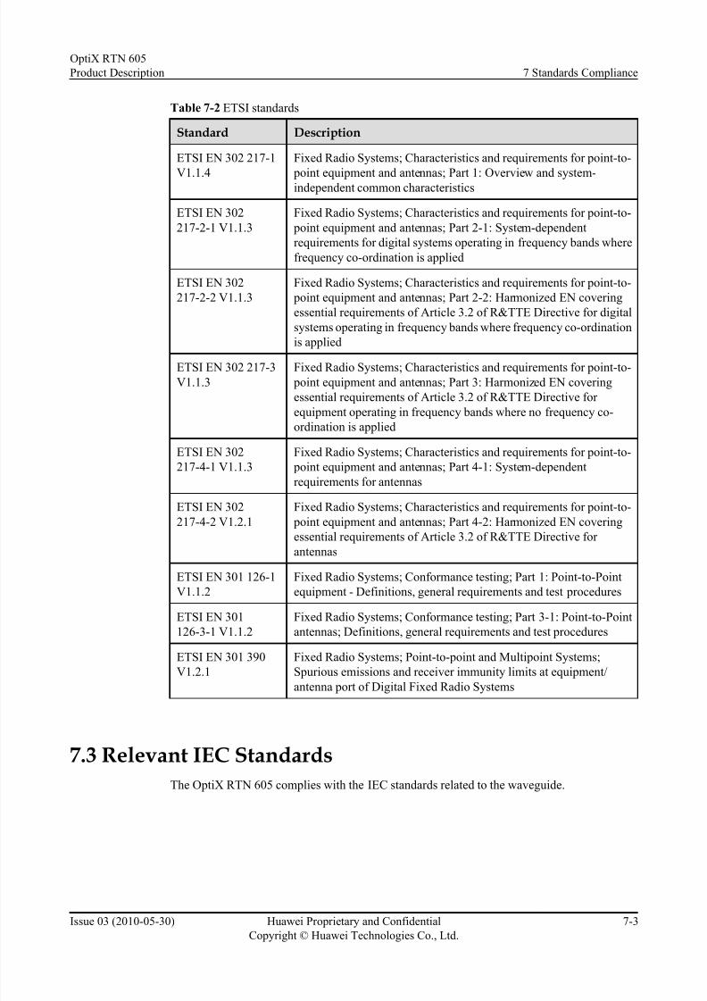
7/22/2019 RTN 605 Product Description(V100R005C00_03)
http://slidepdf.com/reader/full/rtn-605-product-descriptionv100r005c0003 69/107
Table 7-2 ETSI standards
Standard Description
ETSI EN 302 217-1
V1.1.4
Fixed Radio Systems; Characteristics and requirements for point-to-
point equipment and antennas; Part 1: Overview and system-independent common characteristics
ETSI EN 302
217-2-1 V1.1.3
Fixed Radio Systems; Characteristics and requirements for point-to-
point equipment and antennas; Part 2-1: System-dependent
requirements for digital systems operating in frequency bands where
frequency co-ordination is applied
ETSI EN 302
217-2-2 V1.1.3
Fixed Radio Systems; Characteristics and requirements for point-to-
point equipment and antennas; Part 2-2: Harmonized EN covering
essential requirements of Article 3.2 of R&TTE Directive for digital
systems operating in frequency bands where frequency co-ordination
is applied
ETSI EN 302 217-3
V1.1.3
Fixed Radio Systems; Characteristics and requirements for point-to-
point equipment and antennas; Part 3: Harmonized EN covering
essential requirements of Article 3.2 of R&TTE Directive for
equipment operating in frequency bands where no frequency co-
ordination is applied
ETSI EN 302
217-4-1 V1.1.3
Fixed Radio Systems; Characteristics and requirements for point-to-
point equipment and antennas; Part 4-1: System-dependent
requirements for antennas
ETSI EN 302
217-4-2 V1.2.1
Fixed Radio Systems; Characteristics and requirements for point-to-
point equipment and antennas; Part 4-2: Harmonized EN coveringessential requirements of Article 3.2 of R&TTE Directive for
antennas
ETSI EN 301 126-1
V1.1.2
Fixed Radio Systems; Conformance testing; Part 1: Point-to-Point
equipment - Definitions, general requirements and test procedures
ETSI EN 301
126-3-1 V1.1.2
Fixed Radio Systems; Conformance testing; Part 3-1: Point-to-Point
antennas; Definitions, general requirements and test procedures
ETSI EN 301 390
V1.2.1
Fixed Radio Systems; Point-to-point and Multipoint Systems;
Spurious emissions and receiver immunity limits at equipment/
antenna port of Digital Fixed Radio Systems
7.3 Relevant IEC Standards
The OptiX RTN 605 complies with the IEC standards related to the waveguide.
OptiX RTN 605
Product Description 7 Standards Compliance
Issue 03 (2010-05-30) Huawei Proprietary and Confidential
Copyright © Huawei Technologies Co., Ltd.
7-3
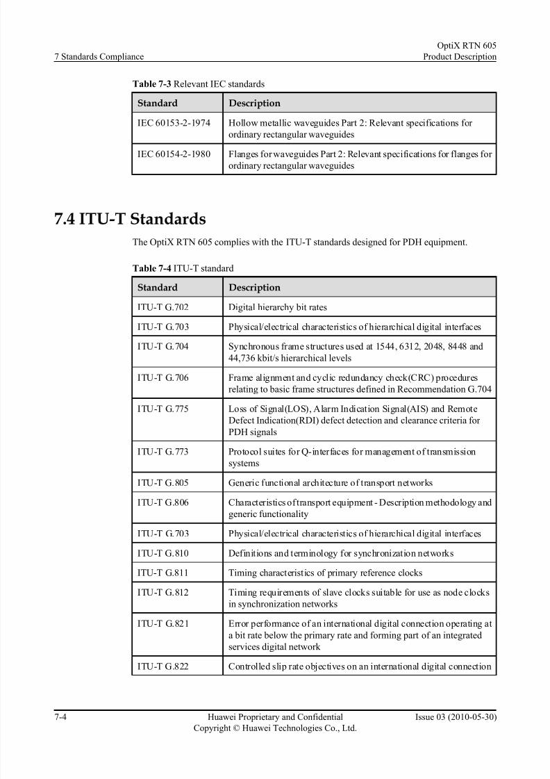
7/22/2019 RTN 605 Product Description(V100R005C00_03)
http://slidepdf.com/reader/full/rtn-605-product-descriptionv100r005c0003 70/107
Table 7-3 Relevant IEC standards
Standard Description
IEC 60153-2-1974 Hollow metallic waveguides Part 2: Relevant specifications for
ordinary rectangular waveguides
IEC 60154-2-1980 Flanges for waveguides Part 2: Relevant specifications for flanges for
ordinary rectangular waveguides
7.4 ITU-T Standards
The OptiX RTN 605 complies with the ITU-T standards designed for PDH equipment.
Table 7-4 ITU-T standardStandard Description
ITU-T G.702 Digital hierarchy bit rates
ITU-T G.703 Physical/electrical characteristics of hierarchical digital interfaces
ITU-T G.704 Synchronous frame structures used at 1544, 6312, 2048, 8448 and
44,736 kbit/s hierarchical levels
ITU-T G.706 Frame alignment and cyclic redundancy check(CRC) procedures
relating to basic frame structures defined in Recommendation G.704
ITU-T G.775 Loss of Signal(LOS), Alarm Indication Signal(AIS) and RemoteDefect Indication(RDI) defect detection and clearance criteria for
PDH signals
ITU-T G.773 Protocol suites for Q-interfaces for management of transmission
systems
ITU-T G.805 Generic functional architecture of transport networks
ITU-T G.806 Characteristics of transport equipment - Description methodology and
generic functionality
ITU-T G.703 Physical/electrical characteristics of hierarchical digital interfaces
ITU-T G.810 Definitions and terminology for synchronization networks
ITU-T G.811 Timing characteristics of primary reference clocks
ITU-T G.812 Timing requirements of slave clocks suitable for use as node clocks
in synchronization networks
ITU-T G.821 Error performance of an international digital connection operating at
a bit rate below the primary rate and forming part of an integrated
services digital network
ITU-T G.822 Controlled slip rate objectives on an international digital connection
7 Standards Compliance
OptiX RTN 605
Product Description
7-4 Huawei Proprietary and Confidential
Copyright © Huawei Technologies Co., Ltd.
Issue 03 (2010-05-30)
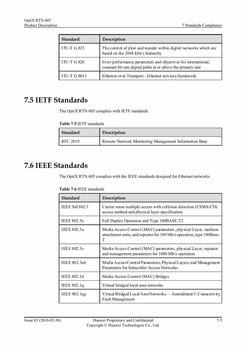
7/22/2019 RTN 605 Product Description(V100R005C00_03)
http://slidepdf.com/reader/full/rtn-605-product-descriptionv100r005c0003 71/107
Standard Description
ITU-T G.823 The control of jitter and wander within digital networks which are
based on the 2048 kbit/s hierarchy
ITU-T G.826 Error performance parameters and objectives for international,constant bit rate digital paths at or above the primary rate
ITU-T G.8011 Ethernet over Transport - Ethernet services framework
7.5 IETF Standards
The OptiX RTN 605 complies with IETF standards.
Table 7-5 IETF standards
Standard Description
RFC 2819 Remote Network Monitoring Management Information Base
7.6 IEEE Standards
The OptiX RTN 605 complies with the IEEE standards designed for Ethernet networks.
Table 7-6 IEEE standards
Standard Description
IEEE Std 802.3 Carrier sense multiple access with collision detection (CSMA/CD)
access method and physical layer specification
IEEE 802.3x Full Duplex Operation and Type 100BASE-T2
IEEE 802.3u Media Access Control (MAC) parameters, physical Layer, medium
attachment units, and repeater for 100 Mb/s operation, type 100Base-
T
IEEE 802.3z Media Access Control (MAC) parameters, physical Layer, repeater
and management parameters for 1000 Mb/s operation
IEEE 802.3ah Media Access Control Parameters, Physical Layers, and Management
Parameters for Subscriber Access Networks
IEEE 802.1d Media Access Control (MAC) Bridges
IEEE 802.1q Virtual bridged local area networks
IEEE 802.1ag Virtual Bridged Local Area Networks — Amendment 5: Connectivity
Fault Management
OptiX RTN 605
Product Description 7 Standards Compliance
Issue 03 (2010-05-30) Huawei Proprietary and Confidential
Copyright © Huawei Technologies Co., Ltd.
7-5

7/22/2019 RTN 605 Product Description(V100R005C00_03)
http://slidepdf.com/reader/full/rtn-605-product-descriptionv100r005c0003 72/107
7.7 Environmental Standards
The OptiX RTN 605 complies with the environmental standards designed for split-mount
microwave equipment.
Table 7-7 Environmental standards
Standard Description
EN 55022 Limits and Methods of Measurement of Radio Disturbance
Characteristics of Information Technology Equipment
CISPR 22 Limits and methods of measurement of radio disturbance
characteristics of information
ETSI EN 301 489-1 Electromagnetic compatibility and Radio spectrum Matters (ERM);Electromagnetic Compatibility (EMC) standard for radio equipment
and services; Part 1: Common technical requirements
ETSI EN 301 489-4 Electromagnetic compatibility and Radio spectrum Matters (ERM);
Electromagnetic Compatibility (EMC) standard for radio equipment
and services; Part 4: Specific conditions for fixed radio links and
ancillary equipment and services
NEBS GR-63-
CORE
Network Equipment-Building System (NEBS) Requirements:
Physical Protection
EN 60950-1 Information technology equipment-Safety-Part 1: General
requirements
UL 60950-1 Information technology equipment-Safety-Part 1: General
requirements
IEC 60825-1 Safety of laser products-Part 1: Equipment classification,
requirements and user's guide
IEC 60825-2 Safety of laser products-Part 2: Safety of optical fiber communication
systems (OFCS)
IEC 60950-1 Information technology equipment-Safety-Part 1: General
requirements
IEC 60950-22
(Outdoor Unit)
Information technology equipment-Safety-Part 22: Equipment to be
installed outdoors
IEC 61000-4-2 Electromagnetic compatibility (EMC) Part 2: Testing and
measurement techniques Section 2: Electrostatic discharge immunity
test Basic EMC Publication
IEC 61000-4-3 Electromagnetic compatibility; Part 3: Testing and measurement
techniques Section 3 radio frequency electromagnetic fields;
immunity test.
7 Standards Compliance
OptiX RTN 605
Product Description
7-6 Huawei Proprietary and Confidential
Copyright © Huawei Technologies Co., Ltd.
Issue 03 (2010-05-30)

7/22/2019 RTN 605 Product Description(V100R005C00_03)
http://slidepdf.com/reader/full/rtn-605-product-descriptionv100r005c0003 73/107

7/22/2019 RTN 605 Product Description(V100R005C00_03)
http://slidepdf.com/reader/full/rtn-605-product-descriptionv100r005c0003 74/107

7/22/2019 RTN 605 Product Description(V100R005C00_03)
http://slidepdf.com/reader/full/rtn-605-product-descriptionv100r005c0003 75/107
A Glossary
Terms are listed in an alphabetical order.
A.1 0-9
A.2 A-E
A.3 F-J
A.4 K-O
A.5 P-T
A.6 U-Z
OptiX RTN 605
Product Description A Glossary
Issue 03 (2010-05-30) Huawei Proprietary and Confidential
Copyright © Huawei Technologies Co., Ltd.
A-1
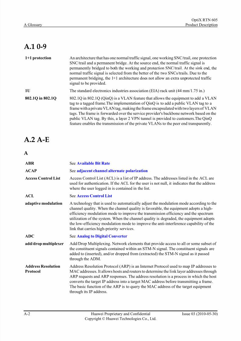
7/22/2019 RTN 605 Product Description(V100R005C00_03)
http://slidepdf.com/reader/full/rtn-605-product-descriptionv100r005c0003 76/107
A.1 0-9
1+1 protection An architecture that has one normal traffic signal, one working SNC/trail, one protectionSNC/trail and a permanent bridge. At the source end, the normal traffic signal is
permanently bridged to both the working and protection SNC/trail. At the sink end, the
normal traffic signal is selected from the better of the two SNCs/trails. Due to the
permanent bridging, the 1+1 architecture does not allow an extra unprotected traffic
signal to be provided.
1U The standard electronics industries association (EIA) rack unit (44 mm/1.75 in.)
802.1Q in 802.1Q 802.1Q in 802.1Q (QinQ) is a VLAN feature that allows the equipment to add a VLAN
tag to a tagged frame.The implementation of QinQ is to add a public VLAN tag to a
frame with a private VLAN tag, making the frame encapsulated with two layers of VLAN
tags. The frame is forwarded over the service provider's backbone network based on the
public VLAN tag. By this, a layer 2 VPN tunnel is provided to customers.The QinQfeature enables the transmission of the private VLANs to the peer end transparently.
A.2 A-E
A
ABR See Available Bit Rate
ACAP See adjacent channel alternate polarization
Access Control List Access Control List (ACL) is a list of IP address. The addresses listed in the ACL areused for authentication. If the ACL for the user is not null, it indicates that the address
where the user logged in is contained in the list.
ACL See Access Control List
adaptive modulation A technology that is used to automatically adjust the modulation mode according to the
channel quality. When the channel quality is favorable, the equipment adopts a high-
efficiency modulation mode to improve the transmission efficiency and the spectrum
utilization of the system. When the channel quality is degraded, the equipment adopts
the low-efficiency modulation mode to improve the anti-interference capability of the
link that carries high-priority services.
ADC See Analog to Digital Converter
add/drop multiplexer Add/Drop Multiplexing. Network elements that provide access to all or some subset of
the constituent signals contained within an STM-N signal. The constituent signals are
added to (inserted), and/or dropped from (extracted) the STM-N signal as it passed
through the ADM.
Address Resolution
Protocol
Address Resolution Protocol (ARP) is an Internet Protocol used to map IP addresses to
MAC addresses. It allows hosts and routers to determine the link layer addresses through
ARP requests and ARP responses. The address resolution is a process in which the host
converts the target IP address into a target MAC address before transmitting a frame.
The basic function of the ARP is to query the MAC address of the target equipment
through its IP address.
A Glossary
OptiX RTN 605
Product Description
A-2 Huawei Proprietary and Confidential
Copyright © Huawei Technologies Co., Ltd.
Issue 03 (2010-05-30)

7/22/2019 RTN 605 Product Description(V100R005C00_03)
http://slidepdf.com/reader/full/rtn-605-product-descriptionv100r005c0003 77/107
adjacent channel
alternate polarization
A channel configuration method, which uses two adjacent channels (a horizontal
polarization wave and a vertical polarization wave) to transmit two signals.
ADM See add/drop multiplexer
Administrative Unit The information structure which provides adaptation between the higher order path layer and the multiplex section layer. It consists of an information payload (the higher order
VC) and an AU pointer which indicates the offset of the payload frame start relative to
the multiplex section frame start.
AF See Assured Forwarding
AGC See Automatic Gain Control
aggregation A collection of objects that makes a whole. An aggregation can be a concrete or
conceptual set of whole-part relationships among objects.
AIS See Alarm Indication Signal
Alarm automatic
report
When an alarm is generated on the device side, the alarm is reported to the N2000. Then,
an alarm panel prompts and the user can view the details of the alarm.
alarm cascading The shunt-wound output of the alarm signals of several subracks or cabinets.
Alarm Filtering An NE reports the detected alarm to the element management system (EMS). Based on
the filter state of the alarm, the EMS determines whether to display or save the alarm
information. If the filter state of an alarm is set to Filter, the alarm is not displayed or
stored on the EMS. The alarm, however, is still monitored by the NE.
Alarm Indication
Signal
A code sent downstream in a digital network as an indication that an upstream failure
has been detected and alarmed. It is associated with multiple transport layers. Note: See
ITU-T Rec. G.707/Y.1322 for specific AIS signals.
Alarm suppression A function used not to monitor alarms for a specific object, which may be the
networkwide equipment, a specific NE, a specific board and even a specific function
module of a specific board.
AM See adaptive modulation
Analog to Digital
Converter
An electronic circuit that converts continuous signals to discrete digital numbers. The
reverse operation is performed by a digital-to-analog converter (DAC).
APS See Automatic Protection Switching
ARP See Address Resolution Protocol
ASK amplitude shift keying
Assured Forwarding Assured Forwarding (AF) is one of the four per-hop behaviors (PHB) defined by the
Diff-Serv workgroup of IETF. AF is suitable for certain key data services that require
assured bandwidth and short delay. For traffic within the limit, AF assures quality in
forwarding. For traffic that exceeds the limit, AF degrades the service class and continues
to forward the traffic instead of discarding the packets.
Asynchronous
Transfer Mode
A data transfer technology based on cell, in which packets allocation relies on channel
demand. It supports fast packet switching to achieve efficient utilization of network
resources. The size of a cell is 53 bytes, which consist of 48-byte payload and 5-byte
header.
ATM See Asynchronous Transfer Mode
ATM PVC ATM Permanent Virtual Circuit
OptiX RTN 605
Product Description A Glossary
Issue 03 (2010-05-30) Huawei Proprietary and Confidential
Copyright © Huawei Technologies Co., Ltd.
A-3

7/22/2019 RTN 605 Product Description(V100R005C00_03)
http://slidepdf.com/reader/full/rtn-605-product-descriptionv100r005c0003 78/107
ATPC See automatic transmit power control
attenuator A device used to increase the attenuation of an Optical Fibre Link. Generally used to
ensure that the signal at the receive end is not too strong.
AU See Administrative UnitAutomatic Gain
Control
A process or means by which gain is automatically adjusted in a specified manner as a
function of a specified parameter, such as received signal level.
Automatic Protection
Switching
Automatic Protection Switching (APS) is the capability of a transmission system to
detect a failure on a working facility and to switch to a standby facility to recover the
traffic.
automatic transmit
power control
A method of adjusting the transmit power based on fading of the transmit signal detected
at the receiver
Available Bit Rate A kind of service categories defined by the ATM forum. ABR only provides possible
forwarding service and applies to the connections that does not require the real-time
quality. It does not provide any guarantee in terms of cell loss or delay.
B
Backward Defect
Indication
When detecting a defect, the sink node of a LSP uses backward defect indication (BDI)
to inform the upstream end of the LSP of a downstream defect along the return path.
bandwidth A range of transmission frequencies that a transmission line or channel can carry in a
network. In fact, it is the difference between the highest and lowest frequencies the
transmission line or channel. The greater the bandwidth, the faster the data transfer rate.
Base Station Controller A logical entity that connects the BTS with the MSC in a GSM network. It interworks
with the BTS through the Abis interface, the MSC through the A interface. It provides
the following functions: Radio resource management, Base station management, Power
control, Handover control, and Traffic measurement. One BSC controls and manages
one or more BTSs in an actual network.
Base Transceiver
Station
A Base Transceiver Station terminates the radio interface. It allows transmission of traffic
and signaling across the air interface. The BTS includes the baseband processing, radio
equipment, and the antenna.
BDI See Backward Defect Indication
BE See best effort
BER See Bit Error Rate
best effort A kind of PHB (Per-Hop-Behavior). In the forwarding process of a DS domain, the trafficof this PHB type features reachability but the DS node does not guarantee the forwarding
quality.
BIOS Basic Input Output System
BIP Bit-Interleaved Parity
bit error An incompatibility between a bit in a transmitted digital signal and the corresponding
bit in the received digital signal.
Bit Error Rate Bit error rate. Ratio of received bits that contain errors. BER is an important index used
to measure the communications quality of a network.
A Glossary
OptiX RTN 605
Product Description
A-4 Huawei Proprietary and Confidential
Copyright © Huawei Technologies Co., Ltd.
Issue 03 (2010-05-30)

7/22/2019 RTN 605 Product Description(V100R005C00_03)
http://slidepdf.com/reader/full/rtn-605-product-descriptionv100r005c0003 79/107

7/22/2019 RTN 605 Product Description(V100R005C00_03)
http://slidepdf.com/reader/full/rtn-605-product-descriptionv100r005c0003 80/107
CIR See Committed Information Rate
Circuit Cross Connect An implementation of MPLS L2VPN through the static configuration of labels.
Circuit Emulation
Service
A function with which the E1/T1 data can be transmitted through ATM networks. At the
transmission end, the interface module packs timeslot data into ATM cells. These ATMcells are sent to the reception end through the ATM network. At the reception end, the
interface module re-assigns the data in these ATM cells to E1/T1 timeslots. The CES
technology guarantees that the data in E1/T1 timeslots can be recovered to the original
sequence at the reception end.
CIST See Common and Internal Spanning Tree
CIST root A switch of the highest priority is elected as the root in an MSTP network.
Class of Service A class object that stores the priority mapping rules. When network congestion occurs,
the class of service (CoS) first processes services by different priority levels from high
to low. If the bandwidth is insufficient to support all services, the CoS dumps the services
of low priority.
Clock tracing The method to keep the time on each node being synchronized with a clock source in a
network.
Co-Channel Dual
Polarization
A channel configuration method, which uses a horizontal polarization wave and a vertical
polarization wave to transmit two signals. The Co-Channel Dual Polarization is twice
the transmission capacity of the single polarization.
Coarse Wavelength
Division Multiplexing
A signal transmission technology that multiplexes widely-spaced optical channels into
the same fiber. CWDM widely spaces wavelengths at a spacing of several nm. CWDM
does not support optical amplifiers and is applied in short-distance chain networking.
Colored packet A packet whose priority is determined by defined colors.
Combined cabinet Two or multiple BTS cabinets of the same type are combined to serve as one BTS.
committed access rate A traffic control method that uses a set of rate limits to be applied to a router interface.
CAR is a configurable method by which incoming and outgoing packets can be classified
into QoS (Quality of Service) groups, and by which the input or output transmission rate
can be defined.
Committed
Information Rate
The rate at which a frame relay network agrees to transfer information in normal
conditions. Namely, it is the rate, measured in bit/s, at which the token is transferred to
the leaky bucket.
Common and Internal
Spanning Tree
Common and Internal Spanning Tree. The single Spanning Tree calculated by STP and
RSTP together with the logical continuation of that connectivity through MST Bridges
and regions, calculatedby MSTP to ensure that all LANs in the Bridged Local Area
Network are simply and fully connected.
compact flash Compact flash (CF) was originally developed as a type of data storage device used in
portable electronic devices. For storage, CompactFlash typically uses flash memory in
a standardized enclosure.
Concatenation A process that combines multiple virtual containers. The combined capacities can be
used a single capacity. The concatenation also keeps the integrity of bit sequence.
connecting plate for
combining cabinets
A plate that connects two adjacent cabinet together at the cabinet top for fixing.
A Glossary
OptiX RTN 605
Product Description
A-6 Huawei Proprietary and Confidential
Copyright © Huawei Technologies Co., Ltd.
Issue 03 (2010-05-30)

7/22/2019 RTN 605 Product Description(V100R005C00_03)
http://slidepdf.com/reader/full/rtn-605-product-descriptionv100r005c0003 81/107
Connectivity Check Ethernet CFM can detect the connectivity between MEPs. The detection is achieved by
each MEP transmitting a Continuity Check Message (CCM) periodically. This detection
is called CC detection.
Constant Bit Rate constant bit rate. A kind of service categories defined by the ATM forum. CBR transfers
cells based on the constant bandwidth. It is applicable to service connections that dependon precise clocking to ensure undistorted transmission.
Constraint Shortest
Path First
An extension of shortest path algorithms like OSPF and IS-IS. The path computed using
CSPF is a shortest path fulfilling set of constrains. It simply means that it runs shortest
path algorithm after pruning those links that violate a given set of constraints. A
constraint could be minimum bandwidth required per link (also know as bandwidth
guaranteed constraint), end-to-end delay, maximum number of link traversed etc. CSPF
is widely used in MPLS Traffic Engineering. The routing using CSPF is known as
Constraint Based Routing (CBR).
Constraint-based
Routed-Label
Distribution Protocol
An alternative to RSVP (Resource ReSerVation Protocol) in MPLS (MultiProtocol
Label Switching) networks. RSVP, which works at the IP (Internet Protocol) level, uses
IP or UDP datagrams to communicate between LSR (Label Switched Routing) peers.
RSVP does not require the maintenance of TCP (Transmission Control Protocol)
sessions, although RSVP must assume responsibility for error control. CR-LDP is
designed to facilitate the routing of LSPs (Label Switched Paths) through TCP sessions
between LSR peers through the communication of label distribution messages during
the session.
continuity check
message
CCM is used to detect the link status.
corrugated tube A pipe which is used for fiber routing.
CoS See Class of Service
CPU See Central Processing Unit
CR-LDP See Constraint-based Routed-Label Distribution Protocol
CRC See Cyclic Redundancy Check
cross polarization
interference
cancellation
A technology used in the case of the Co-Channel Dual Polarization (CCDP) to eliminate
the cross-connect interference between two polarization waves in the CCDP.
CSPF See Constraint Shortest Path First
Customer Edge A part of BGP/MPLS IP VPN model. It provides interfaces for direct connection to the
Service Provider (SP) network. A CE can be a router, switch, or host.
CWDM See Coarse Wavelength Division Multiplexing
Cyclic Redundancy
Check
A procedure used in checking for errors in data transmission. CRC error checking uses
a complex calculation to generate a number based on the data transmitted. The sending
device performs the calculation before transmission and includes it in the packet that it
sends to the receiving device. The receiving device repeats the same calculation after
transmission. If both devices obtain the same result, it is assumed that the transmission
was error free. The procedure is known as a redundancy check because each transmission
includes not only data but extra (redundant) error-checking values.
OptiX RTN 605
Product Description A Glossary
Issue 03 (2010-05-30) Huawei Proprietary and Confidential
Copyright © Huawei Technologies Co., Ltd.
A-7

7/22/2019 RTN 605 Product Description(V100R005C00_03)
http://slidepdf.com/reader/full/rtn-605-product-descriptionv100r005c0003 82/107
D
Data Circuit-terminal
Equipment
Also Data Communications Equipment (DCE) and Data Carrier Equipment (DCE). The
basic function of a DCE is to convert data from one interface, such as a digital signal, to
another interface, such as an analog signal. One example of DCE is a modem.Data Communication
Network
A communication network used in a TMN or between TMNs to support the Data
Communication Function (DCF).
Data Communications
Channel
The data channel that uses the D1-D12 bytes in the overhead of an STM-N signal to
transmit information on operation, management, maintenance and provision (OAM&P)
between NEs. The DCC channels that are composed of bytes D1-D3 is referred to as the
192 kbit/s DCC-R channel. The other DCC channel that are composed of bytes D4-D12
is referred to as the 576 kbit/s DCC-M channel.
Datagram A kind of PDU which is used in Connectionless Network Protocol, such as IP datagram,
UDP datagram.
DC See Direct CurrentDC-C See DC-Return Common (with Ground)
DC-I See DC-Return Isolate (with Ground)
DC-Return Common
(with Ground)
A power system, in which the BGND of the DC return conductor is short-circuited with
the PGND on the output side of the power supply cabinet and also on the line between
the output of the power supply cabinet and the electric equipment.
DC-Return Isolate
(with Ground)
A power system, in which the BGND of the DC return conductor is short-circuited with
the PGND on the output side of the power supply cabinet and is isolated from the PGND
on the line between the output of the power supply cabinet and the electric equipment.
DCC See Data Communications Channel
DCE See Data Circuit-terminal Equipment
DCN See Data Communication Network
DDF See Digital Distribution Frame
DDN See Digital Data Network
DE See discard eligible
Detour LSP The LSP that is used to re-route traffic around a failure in one-to-one backup.
diamond-shaped nut A type of nut that is used to fasten the wiring frame to the cabinet.
Differentiated Services A service architecture that provides the end-to-end QoS function. It consists of a series
of functional units implemented at the network nodes, including a small group of per-
hop forwarding behaviors, packet classification functions, and traffic conditioning
functions such as metering, marking, shaping and policing.
Differentiated Services
Code Point
Differentiated Services CodePoint. A marker in the header of each IP packet using bits
0-6 in the DS field. Routers provide differentiated classes of services to various service
streams/flows based on this marker. In other words, routers select corresponding PHB
according to the DSCP value.
DiffServ See Differentiated Services
Digital Data Network A high-quality data transport tunnel that combines the digital channel (such as fiber
channel, digital microwave channel, or satellite channel) and the cross multiplex
technology.
A Glossary
OptiX RTN 605
Product Description
A-8 Huawei Proprietary and Confidential
Copyright © Huawei Technologies Co., Ltd.
Issue 03 (2010-05-30)
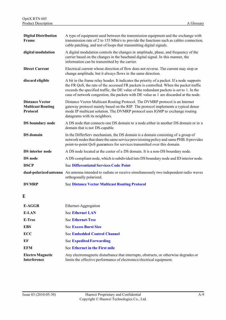
7/22/2019 RTN 605 Product Description(V100R005C00_03)
http://slidepdf.com/reader/full/rtn-605-product-descriptionv100r005c0003 83/107
7/22/2019 RTN 605 Product Description(V100R005C00_03)
http://slidepdf.com/reader/full/rtn-605-product-descriptionv100r005c0003 84/107
electromagnetic
compatibility
Electromagnetic compatibility is the condition which prevails when telecommunications
equipment is performing its individually designed function in a common electromagnetic
environment without causing or suffering unacceptable degradation due to unintentional
electromagnetic interference to or from other equipment in the same environment.
[NTIA]ElectroStatic Discharge The sudden and momentary electric current that flows between two objects at different
electrical potentials caused by direct contact or induced by an electrostatic field.
Embedded Control
Channel
An ECC provides a logical operations channel between SDH NEs, utilizing a data
communications channel (DCC) as its physical layer.
EMC See electromagnetic compatibility
EMI See Electro Magnetic Interference
Engineering label A mark on a cable, a subrack, or a cabinet for identification.
EPLn See Ethernet Private LAN
equalization A method of avoiding selective fading of frequencies. Equalization can compensate for the changes of amplitude frequency caused by frequency selective fading.
ERPS See ethernet ring protection switching
ES-IS End System to Intermediate System
ESD See ElectroStatic Discharge
ESD jack Electrostatic discharge jack. A hole in the cabinet or shelf, which connect the shelf or
cabinet to the insertion of ESD wrist strap.
ETH-CC Ethernet Continuity Check
ETH-LB Ethernet Loopback
ETH-LT Ethernet Link Trace
Ethernet A technology complemented in LAN. It adopts Carrier Sense Multiple Access/Collision
Detection. The speed of an Ethernet interface can be 10 Mbit/s, 100 Mbit/s, 1000 Mbit/
s or 10000 Mbit/s. The Ethernet network features high reliability and easy maintaining..
Ethernet in the First
mile
Last mile access from the broadband device to the user community. The EFM takes the
advantages of the SHDSL.bis technology and the Ethernet technology. The EFM
provides both the traditional voice service and internet access service of high speed. In
addition, it meets the users' requirements on high definition television system (HDTV)
and Video On Demand (VOD).
Ethernet LAN Ethernet LAN. A L2VPN service type that is provided for the user Ethernet in different
domains over the PSN network. For the user Ethernet, the entire PSN network serves as
a Layer 2 switch.
Ethernet Private LAN Both a LAN service and a private service. Transport bandwidth is never shared between
different customers.
ethernet ring
protection switching
protection switching mechanisms for ETH layer Ethernet ring topologies.
Ethernet Virtual
Private LAN
A service that is both a LAN service and a virtual private service.
Ethernet-Tree etherenet tree. An Ethernet service type that is based on a Point-to-multipoint Ethernet
Virtual Connection.
A Glossary
OptiX RTN 605
Product Description
A-10 Huawei Proprietary and Confidential
Copyright © Huawei Technologies Co., Ltd.
Issue 03 (2010-05-30)

7/22/2019 RTN 605 Product Description(V100R005C00_03)
http://slidepdf.com/reader/full/rtn-605-product-descriptionv100r005c0003 85/107
ETS European Telecommunication Standards
ETSI See European Telecommunications Standards Institute
ETSI 300mm cabinet A cabinet which is 600mm in width and 300mm in depth, compliant with the standards
of the ETSI.European
Telecommunications
Standards Institute
A standards-setting body in Europe. Also the standards body responsible for GSM.
EVPL Ethernet Virtual Private Line
EVPLn See Ethernet Virtual Private LAN
Excess Burst Size excess burst size. In the single rate three color marker (srTCM) mode, the traffic control
is realized by the token buckets C and E. Excess burst size is a parameter used to define
the capacity of token bucket E, that is, the maximum burst IP packet size when the
information is transferred at the committed information rate. This parameter must be
larger than 0. It is recommended that this parameter should be not less than the maximumlength of the IP packet that might be forwarded.
Exercise Switching An operation to check if the protection switching protocol functions normally. The
protection switching is not really performed.
Expedited Forwarding Expedited Forwarding (EF) is the highest order QoS in the Diff-Serv network. EF PHB
is suitable for services that demand low packet loss ratio, short delay, and broad
bandwidth. In all the cases, EF traffic can guarantee a transmission rate equal to or faster
than the set rate. The DSCP value of EF PHB is "101110".
A.3 F-J
F
Failure If the fault persists long enough to consider the ability of an item with a required function
to be terminated. The item may be considered as having failed; a fault has now been
detected.
Fast Ethernet A type of Ethernet with a maximum transmission rate of 100 Mbit/s. It complies with
the IEEE 802.3u standard and extends the traditional media-sharing Ethernet standard.
fast link pulse The likn pulse that is used to encode information during automatic negotiation.
FCS Frame Check Sequence
FD See frequency diversity
FDI See Forward Defect Indication
FE See Fast Ethernet
FEC See Forward Error Correction
FFD Fast Failure Detection
Fiber Connector A device installed at the end of a fiber, optical source or receive unit. It is used to couple
the optical wave to the fiber when connected to another device of the same type. A
connector can either connect two fiber ends or connect a fiber end and a optical source
(or a detector).
OptiX RTN 605
Product Description A Glossary
Issue 03 (2010-05-30) Huawei Proprietary and Confidential
Copyright © Huawei Technologies Co., Ltd.
A-11

7/22/2019 RTN 605 Product Description(V100R005C00_03)
http://slidepdf.com/reader/full/rtn-605-product-descriptionv100r005c0003 86/107
fiber patch cord A kind of fiber used for connections between the subrack and the ODF, and for
connections between subracks or inside a subrack.
Field Programmable
Gate Array
A type of semi-customized circuit used in the Application Specific Integrated Circuit
(ASIC) field. It is developed on the basis of the programmable components, such as the
PAL, GAL, and EPLD. It not only remedies the defects of customized circuits, but alsoovercomes the disadvantage of the original programmable components in terms of the
limited number of gate arraies.
FIFO See First in First out
File Transfer Protocol A member of the TCP/IP suite of protocols, used to copy files between two computers
on the Internet. Both computers must support their respective FTP roles: one must be an
FTP client and the other an FTP server.
First in First out A stack management mechanism. The first saved data is first read and invoked.
FLP See fast link pulse
Forced switch This function forces the service to switch from the working channel to the protectionchannel, with the service not to be restored automatically. This switch occurs regardless
of the state of the protection channels or boards, unless the protection channels or boards
are satisfying a higher priority bridge request.
Forward Defect
Indication
Forward defect indication (FDI) is generated and traced forward to the sink node of the
LSP by the node that first detects defects. It includes fields to indicate the nature of the
defect and its location. Its primary purpose is to suppress alarms being raised at affected
higher level client LSPs and (in turn) their client layers.
Forward Error
Correction
A bit error correction technology that adds the correction information to the payload at
the transmit end. Based on the correction information, the bit errors generated during
transmission are corrected at the receive end.
Forwarding plane Also referred to as the data plane. The forwarding plane is connection-oriented, and can
be used in Layer 2 networks such as an ATM network.
FPGA See Field Programmable Gate Array
Fragment Piece of a larger packet that has been broken down to smaller units.
Fragmentation Process of breaking a packet into smaller units when transmitting over a network medium
that can not support the original size of the packet.
frame A frame, starting with a header, is a string of bytes with a specified length. Frame length
is represented by the sampling circle or the total number of bytes sampled during a circle.
A header comprises one or a number of bytes with pre-specified values. In other words,
a header is a code segment that reflects the distribution (diagram) of the elements pre-
specified by the sending and receiving parties.
frequency diversity A diversity scheme that enables two or more microwave frequencies with a certain
frequency interval are used to transmit/receive the same signal and selection is then
performed between the two signals to ease the impact of fading.
FTP See File Transfer Protocol
Full duplex The system that can transmit information in both directions on a communication link.On
the communication link, both parties can send and receive data at the same time.
A Glossary
OptiX RTN 605
Product Description
A-12 Huawei Proprietary and Confidential
Copyright © Huawei Technologies Co., Ltd.
Issue 03 (2010-05-30)

7/22/2019 RTN 605 Product Description(V100R005C00_03)
http://slidepdf.com/reader/full/rtn-605-product-descriptionv100r005c0003 87/107

7/22/2019 RTN 605 Product Description(V100R005C00_03)
http://slidepdf.com/reader/full/rtn-605-product-descriptionv100r005c0003 88/107
H
H-QoS Hierarchical Quality of Service
HA See High Availability
half-duplex A transmitting mode in which a half-duplex system provides for communication in both
directions, but only one direction at a time (not simultaneously). Typically, once a party
begins receiving a signal, it must wait for the transmitter to stop transmitting, before
replying.
HDB3 High Density Bipolar Code 3
HDLC See High level Data Link Control procedure
High Availability The ability of a system to continuously perform its functions during a long period, which
may exceeds the suggested working time of the independent components. You can obtain
the high availability (HA) by using the error tolerance method. Based on learning cases
one by one, you must also clearly understand the limitations of the system that requires
an HA ability and the degree to which the ability can reach.
High level Data Link
Control procedure
A data link protocol from ISO for point-to-point communications over serial links.
Derived from IBM's SDLC protocol, HDLC has been the basis for numerous protocols
including X.25, ISDN, T1, SS7, GSM, CDPD, PPP and others. Various subsets of HDLC
have been developed under the name of Link Access Procedure (LAP).
High Speed Downlink
Packet Access
A modulating-demodulating algorithm put forward in 3GPP R5 to meet the requirement
for asymmetric uplink and downlink transmission of data services. It enables the
maximum downlink data service rate to reach 14.4 Mbit/s without changing the
WCDMA network topology.
Hold priority The priority of the tunnel with respect to holding resources, ranging from 0 (indicates
the highest priority) to 7. It is used to determine whether the resources occupied by thetunnel can be preempted by other tunnels.
Hop A network connection between two distant nodes. For Internet operation a hop represents
a small step on the route from one main computer to another.
hot standby A mechanism of ensuring device running security. The environment variables and
storage information of each running device are synchronized to the standby device. When
the faults occur on the running device, the standby device can take over the services in
the faulty device in automatic or manual way to ensure the normal running of the entire
system.
HP Higher Order Path
HSDPA See High Speed Downlink Packet Access
HSM Hitless Switch Mode
HTB High Tributary Bus
hybrid radio The hybrid transmission of Native E1 and Native Ethernet signals. Hybrid radio supports
the AM function.
I
ICMP See Internet Control Messages Protocol
IDU See indoor unit
A Glossary
OptiX RTN 605
Product Description
A-14 Huawei Proprietary and Confidential
Copyright © Huawei Technologies Co., Ltd.
Issue 03 (2010-05-30)

7/22/2019 RTN 605 Product Description(V100R005C00_03)
http://slidepdf.com/reader/full/rtn-605-product-descriptionv100r005c0003 89/107
IEC See International Electrotechnical Commission
IEEE See Institute of Electrical and Electronics Engineers
IETF The Internet Engineering Task Force
IF See intermediate frequency
IGMP See Internet Group Management Protocol
IGMP snooping A multicast constraint mechanism running on a layer 2 device. This protocol manages
and controls the multicast group by listening to and analyze the Internet Group
Management Protocol (IGMP) packet between hosts and layer 3 devices. In this manner,
the spread of the multicast data on layer 2 network can be prevented efficiently.
IMA See Inverse Multiplexing over ATM
indoor unit The indoor unit of the split-structured radio equipment. It implements accessing,
multiplexing/demultiplexing, and IF processing for services.
Inloop A method of looping the signals from the cross-connect unit back to the cross-connectunit.
Institute of Electrical
and Electronics
Engineers
A society of engineering and electronics professionals based in the United States but
boasting membership from numerous other countries. The IEEE focuses on electrical,
electronics, computer engineering, and science-related matters.
Interface board area The area for the interface boards on the subrack.
intermediate frequency The transitional frequency between the frequencies of a modulated signal and an RF
signal.
Intermediate System The basic unit in the IS-IS protocol used to transmit routing information and generate
routes.
Intermediate System to
Intermediate System
A protocol used by network devices (routers) .IS-IS is a kind of Interior Gateway Protocol
(IGP), used within the ASs. It is a link status protocol using Shortest Path First (SPF)
algorithm to calculate the route.
Internal Spanning Tree Internal spanning tree. A segment of CIST in a certain MST region. An IST is a special
MSTI whose ID is 0.
International
Electrotechnical
Commission
The International Electrotechnical Commission (IEC) is an international and non-
governmental standards organization dealing with electrical and electronical standards.
International
Organization for
Standardization
ISO (International Organization for Standardization) is the world's largest developer and
publisher of International Standards.
Internet Control
Messages Protocol
ICMP belongs to the TCP/IP protocol suite. It is used to send error and control messages
during the transmission of IP-type data packets.
Internet Group
Management Protocol
The protocol for managing the membership of Internet Protocol multicast groups among
the TCP/IP protocols. It is used by IP hosts and adjacent multicast routers to establish
and maintain multicast group memberships.
Internet Protocol The TCP/IP standard protocol that defines the IP packet as the unit of information sent
across an internet and provides the basis for connectionless, best-effort packet delivery
service. IP includes the ICMP control and error message protocol as an integral part. The
entire protocol suite is often referred to as TCP/IP because TCP and IP are the two
fundamental protocols. IP is standardized in RFC 791.
OptiX RTN 605
Product Description A Glossary
Issue 03 (2010-05-30) Huawei Proprietary and Confidential
Copyright © Huawei Technologies Co., Ltd.
A-15

7/22/2019 RTN 605 Product Description(V100R005C00_03)
http://slidepdf.com/reader/full/rtn-605-product-descriptionv100r005c0003 90/107
Internet Protocol
Version 6
A update version of IPv4. It is also called IP Next Generation (IPng). The specifications
and standardizations provided by it are consistent with the Internet Engineering Task
Force (IETF).Internet Protocol Version 6 (IPv6) is also called. It is a new version of the
Internet Protocol, designed as the successor to IPv4. The specifications and
standardizations provided by it are consistent with the Internet Engineering Task Force(IETF).The difference between IPv6 and IPv4 is that an IPv4 address has 32 bits while
an IPv6 address has 128 bits.
Inverse Multiplexing
over ATM
Inverse Multiplexing over ATM. The ATM inverse multiplexing technique involves
inverse multiplexing and de-multiplexing of ATM cells in a cyclical fashion among links
grouped to form a higher bandwidth logical link whose rate is approximately the sum of
the link rates. This is referred to as an IMA group.
IP See Internet Protocol
IPv6 See Internet Protocol Version 6
IS-IS See Intermediate System to Intermediate System
ISO See International Organization for Standardization
IST See Internal Spanning Tree
ITU-T International Telecommunication Union - Telecommunication Standardization Sector
IVL Independence VLAN learning
J
Jitter Short waveform variations caused by vibration, voltage fluctuations, and control system
instability.
A.4 K-O
L
L2VPN See Layer 2 virtual private network
Label Switched Path A sequence of hops (R0...Rn) in which a packet travels from R0 to Rn through label
switching mechanisms. A label-switched path can be chosen dynamically, based on
normal routing mechanisms, or through configuration.
Label Switching Router The Label Switching Router (LSR) is the basic element of MPLS network. All LSRssupport the MPLS protocol. The LSR is composed of two parts: control unit and
forwarding unit. The former is responsible for allocating the label, selecting the route,
creating the label forwarding table, creating and removing the label switch path; the latter
forwards the labels according to groups received in the label forwarding table.
LACP See Link Aggregation Control Protocol
LAG See link aggregation group
LAN See Local Area Network
LAPD Link Access Procedure on the D channel
LAPS Link Access Procedure-SDH
A Glossary
OptiX RTN 605
Product Description
A-16 Huawei Proprietary and Confidential
Copyright © Huawei Technologies Co., Ltd.
Issue 03 (2010-05-30)

7/22/2019 RTN 605 Product Description(V100R005C00_03)
http://slidepdf.com/reader/full/rtn-605-product-descriptionv100r005c0003 91/107
Laser A component that generates directional optical waves of narrow wavelengths. The laser
light has better coherence than ordinary light. The fiber system takes the semi-conductor
laser as the light source.
layer 2 switch A data forwarding method. In LAN, a network bridge or 802.3 Ethernet switch transmits
and distributes packet data based on the MAC address. Since the MAC address is thesecond layer of the OSI model, this data forwarding method is called layer 2 switch.
Layer 2 virtual private
network
A virtual private network realized in the packet switched (IP/MPLS) network by Layer
2 switching technologies.
LB See Loopback
LCAS See Link Capacity Adjustment Scheme
LDPC Low-Density Parity Check code
line rate forwarding The line rate equals the maximum transmission rate capable on a given type of media.
Link Aggregation
Control Protocol
Link Aggregation Control Protocol (LACP) is part of an IEEE specification (802.3ad)
that allows you to bundle several physical ports to form a single logical channel. LACPallows a switch to negotiate an automatic bundle by sending LACP packets to the peer.
link aggregation group An aggregation that allows one or more links to be aggregated together to form a link
aggregation group so that a MAC clientcan treat the link aggregation group as if it were
a single link.
Link Capacity
Adjustment Scheme
The Link Capacity Adjustment Scheme (LCAS) is designed to allow the dynamic
provisioning of bandwidth, using VCAT, to meet customer requirements.
Link Protection Protection provided by the bypass tunnel for the link on the working tunnel. The link is
a downstream link adjacent to the PLR. When the PLR fails to provide node protection,
the link protection should be provided.
LMSP Linear Multiplex Section Protection
Local Area Network A network formed by the computers and workstations within the coverage of a few square
kilometers or within a single building. It features high speed and low error rate. Ethernet,
FDDI, and Token Ring are three technologies used to implement a LAN. Current LANs
are generally based on switched Ethernet or Wi-Fi technology and running at 1,000 Mbit/
s (that is, 1 Gbit/s).
Locked switching When the switching condition is satisfied, this function disables the service from being
switched from the working channel to the protection channel. When the service has been
switched, the function enables the service to be restored from the protection channel to
the working channel.
LOF See Loss Of Frame
LOM Loss Of Multiframe
Loopback A troubleshooting technique that returns a transmitted signal to its source so that the
signal or message can be analyzed for errors.
LOP See Loss Of Pointer
LOS See Loss Of Signal
Loss Of Frame A condition at the receiver or a maintenance signal transmitted in the PHY overhead
indicating that the receiving equipment has lost frame delineation. This is used to monitor
the performance of the PHY layer.
OptiX RTN 605
Product Description A Glossary
Issue 03 (2010-05-30) Huawei Proprietary and Confidential
Copyright © Huawei Technologies Co., Ltd.
A-17

7/22/2019 RTN 605 Product Description(V100R005C00_03)
http://slidepdf.com/reader/full/rtn-605-product-descriptionv100r005c0003 92/107
Loss Of Pointer Loss of Pointer: A condition at the receiver or a maintenance signal transmitted in the
PHY overhead indicating that the receiving equipment has lost the pointer to the start of
cell in the payload. This is used to monitor the performance of the PHY layer.
Loss Of Signal Loss of signal (LOS) indicates that there are no transitions occurring in the received
signal.
Lower subrack The subrack close to the bottom of the cabinet when a cabinet contains several subracks.
LP Lower Order Path
LPT Link State Path Through
LSP See Label Switched Path
LSR See Label Switching Router
M
MA See Maintenance Association
MAC See Medium Access Control
MAC See Media Access Control
MADM Multi Add-Drop Multiplexer
Maintenance
Association
That portion of a Service Instance, preferably all of it or as much as possible, the
connectivity of which is maintained by CFM. It is also a full mesh of Maintenance
Entities.
Maintenance
association End Point
A MEP is an actively managed CFM Entity, associated with a specific DSAP of a Service
Instance, which can generate and receive CFM frames and track any responses. It is an
end point of a single Maintenance Association, and terminates a separate MaintenanceEntity for each of the other MEPs in the same Maintenance Association.
Maintenance Domain The Maintenance Domain (MD) refers to the network or the part of the network for which
connectivity is managed by CFM. The devices in an MD are managed by a single ISP.
Maintenance Point Maintenance Point (MP) is one of either a MEP or a MIP.
Management
Information Base
A type of database used for managing the devices in a communications network. It
comprises a collection of objects in a (virtual) database used to manage entities (such as
routers and switches) in a network.
Manual switching A protection switching. When the protection path is normal and there is no request of a
higher level switching, the service is manually switched from the working path to the
protection path, to test whether the network still has the protection capability.
Maximum Transfer
Unit
The MTU (Maximum Transmission Unit) is the size of the largest datagram that can be
sent over a network.
MBS Maximum Burst Size
MCF See Message Communication Function
MD See Maintenance Domain
MDI See Medium Dependent Interface
Mean Time To Repair The average time that a device will take to recover from a failure.
A Glossary
OptiX RTN 605
Product Description
A-18 Huawei Proprietary and Confidential
Copyright © Huawei Technologies Co., Ltd.
Issue 03 (2010-05-30)

7/22/2019 RTN 605 Product Description(V100R005C00_03)
http://slidepdf.com/reader/full/rtn-605-product-descriptionv100r005c0003 93/107
Media Access Control A protocol at the media access control sublayer. The protocol is at the lower part of the
data link layer in the OSI model and is mainly responsible for controlling and connecting
the physical media at the physical layer. When transmitting data, the MAC protocol
checks whether to be able to transmit data. If the data can be transmitted, certain control
information is added to the data, and then the data and the control information aretransmitted in a specified format to the physical layer. When receiving data, the MAC
protocol checks whether the information is correct and whether the data is transmitted
correctly. If the information is correct and the data is transmitted correctly, the control
information is removed from the data and then the data is transmitted to the LLC layer.
Medium Access
Control
A general reference to the low-level hardware protocols used to access a particular
network. The term MAC address is often used as a synonym for physical addresses.
Medium Dependent
Interface
The electrical and mechanical interface between the equipment and the media
transmission.
MEP See Maintenance association End Point
MessageCommunication
Function
The MCF is composed of a protocol stack that allows exchange of managementinformation with their prs .
MIB See Management Information Base
MIP Maintenance Intermediate Point
MLPPP See Multi-link Point to Point Protocol
mount angle An L-shape steel sheet. One side is fixed on the front panel with screws, and the other
side is fixed on the installation hole with screws. On both sides of a rack, there is an L-
shaped metal fastener. This ensures that internal components are closely connected with
the rack. Normally, an internal component is installed with two mount angles.
MP See Maintenance Point
MPID Maintenance Point Identification
MPLS See Multi-Protocol Label Switch
MPLS L2VPN The MPLS L2VPN provides the Layer 2 VPN service based on an MPLS network.In
this case, on a uniform MPLS network, the carrier is able to provide Layer 2 VPNs of
different media types, such as ATM, FR, VLAN, Ethernet, and PPP.
MPLS OAM The MPLS OAM provides continuity check for a single LSP, and provides a set of fault
detection tools and fault correct mechanisms for MPLS networks. The MPLS OAM and
relevant protection switching components implement the detection function for the CR-
LSP forwarding plane, and perform the protection switching in 50 ms after a fault occurs.
In this way, the impact of a fault can be lowered to the minimum.
MPLS TE Multiprotocol Label Switching Traffic Engineering
MPLS TE tunnel In the case of reroute deployment, or when traffic needs to be transported through
multiple trails, multiple LSP tunnels might be used. In traffic engineering, such a group
of LSP tunnels are referred to as TE tunnels. An LSP tunnel of this kind has two
identifiers. One is the Tunnel ID carried by the SENDER object, and is used to uniquely
define the TE tunnel. The other is the LSP ID carried by the SENDER_TEMPLATE or
FILTER_SPEC object.
MS See Multiplex Section
MSP See multiplex section protection
OptiX RTN 605
Product Description A Glossary
Issue 03 (2010-05-30) Huawei Proprietary and Confidential
Copyright © Huawei Technologies Co., Ltd.
A-19

7/22/2019 RTN 605 Product Description(V100R005C00_03)
http://slidepdf.com/reader/full/rtn-605-product-descriptionv100r005c0003 94/107
MSTI See Multiple Spanning Tree Instance
MSTP See Multiple Spanning Tree Protocol
MTBF Mean Time Between Failure
MTTR See Mean Time To Repair
MTU See Maximum Transfer Unit
Multi-link Point to
Point Protocol
A protocol used in ISDN connections. MLPPP lets two B channels act as a single line,
doubling connection rates to 128Kbps.
Multi-Protocol Label
Switch
A technology that uses short tags of fixed length to encapsulate packets in different link
layers, and provides connection-oriented switching for the network layer on the basis of
IP routing and control protocols. It improves the cost performance and expandability of
networks, and is beneficial to routing.
Multicast A process of transmitting packets of data from one source to many destinations. The
destination address of the multicast packet uses Class D address, that is, the IP address
ranges from 224.0.0.0 to 239.255.255.255. Each multicast address represents a multicastgroup rather than a host.
Multiple Spanning
Tree Instance
Multiple spanning tree instance. One of a number of Spanning Trees calculated by MSTP
within an MST Region, to provide a simply and fully connected active topology for
frames classified as belonging to a VLAN that is mapped to the MSTI by the MST
Configuration. A VLAN cannot be assigned to multiple MSTIs.
Multiple Spanning
Tree Protocol
Multiple spanning tree protocol. The MSTP can be used in a loop network. Using an
algorithm, the MSTP blocks redundant paths so that the loop network can be trimmed
as a tree network. In this case, the proliferation and endless cycling of packets is avoided
in the loop network.The protocol that introduces the mapping between VLANs and
multiple spanning trees. This solves the problem that data cannot be normally forwarded
in a VLAN because in STP/RSTP, only one spanning tree corresponds to all the VLANs.
Multiple Spanning
Tree Region
The MST region consists of switches that support the MSTP in the LAN and links among
them. Switches physically and directly connected and configured with the same MST
region attributes belong to the same MST region. The attributes for the same MST region
are as follows: Same region name Same revision level Same mapping relation between
the VLAN ID to MSTI
Multiplex Section The trail between and including two multiplex section trail termination functions.
multiplex section
protection
A function, which is performed to provide capability for switching a signal between and
including two multiplex section termination (MST) functions, from a "working" to a
"protection" channel.
N
N+1 protection A radio link protection system composed of N working channels and one protection
channel.
NE See Network Element
NE Explorer The main operation interface, of the U2000, which is used to manage the OptiX
equipment. In the NE Explorer, the user can configure, manage and maintain the NE,
boards, and ports on a per-NE basis.
A Glossary
OptiX RTN 605
Product Description
A-20 Huawei Proprietary and Confidential
Copyright © Huawei Technologies Co., Ltd.
Issue 03 (2010-05-30)

7/22/2019 RTN 605 Product Description(V100R005C00_03)
http://slidepdf.com/reader/full/rtn-605-product-descriptionv100r005c0003 95/107
Network Element A network element (NE) contains both the hardware and the software running on it. One
NE is at least equipped with one system control board which manages and monitors the
entire network element. The NE software runs on the system control board.
network management
system
The network management system in charge of the operation, administration, and
maintenance of a network.
Network Service Access
Point
A network address defined by ISO, through which entities on the network layer can
access OSI network services.
Network to Network
Interface
This is an internal interface within a network linking two or more elements.
next hop The next router to which a packet is sent from any given router as it traverses a network
on its journey to its final destination.
NLP Normal Link Pulse
NMS See network management system
NNHOP Next-Next-Hop
NNI See Network to Network Interface
Node A node stands for a managed device in the network.For a device with a single frame, one
node stands for one device.For a device with multiple frames, one node stands for one
frame of the device.Therefore, a node does not always mean a device.
Node Protection A parameter of the FRR protection. It indicates that the bypass tunnel should be able to
protect the downstream node that is involved in the working tunnel and adjacent to the
PLR. The node cannot be a merge point, and the bypass tunnel should also be able to
protect the downstream link that is involved in the working tunnel and adjacent to the
PLR.
non-gateway network
element
A network element whose communication with the NM application layer must be
transferred by the gateway network element application layer.
non-GNE See non-gateway network element
NSAP See Network Service Access Point
NSF Not Stop Forwarding
NSMI Network Serial Multiplexed Interface
O
OAM See Operation, Administration and Maintenanc
ODF See Optical Distribution Frame
ODU See outdoor unit
One-to-One Backup A local repair method in which a backup tunnel is separately created for each protected
tunnel at a PLR.
Open Shortest Path
First
A link-state, hierarchical interior gateway protocol (IGP) for network routing. Dijkstra's
algorithm is used to calculate the shortest path tree. It uses cost as its routing metric. A
link state database is constructed of the network topology which is identical on all routers
in the area.
OptiX RTN 605
Product Description A Glossary
Issue 03 (2010-05-30) Huawei Proprietary and Confidential
Copyright © Huawei Technologies Co., Ltd.
A-21

7/22/2019 RTN 605 Product Description(V100R005C00_03)
http://slidepdf.com/reader/full/rtn-605-product-descriptionv100r005c0003 96/107
Open Systems
Interconnection
A standard or "reference model" (officially defined by the International Organization of
Standards (ISO)) for how messages should be transmitted between any two points in a
telecommunication network. The reference model defines seven layers of functions that
take place at each end of a communication.
Operation,Administration and
Maintenanc
Operation, Administration and Maintenance. A group of network support functions thatmonitor and sustain segment operation, activities that are concerned with, but not limited
to, failure detection, notification, location, and repairs that are intended to eliminate faults
and keep a segment in an operational state and support activities required to provide the
services of a subscriber access network to users/subscribers.
Optical Distribution
Frame
A frame which is used to transfer and spool fibers.
orderwire A channel that provides voice communication between operation engineers or
maintenance engineers of different stations.
OSI See Open Systems Interconnection
OSP OptiX Software Platform
OSPF See Open Shortest Path First
outdoor unit The outdoor unit of the split-structured radio equipment. It implements frequency
conversion and amplification for RF signals.
Outloop A method of looping back the input signals received at an port to an output port without
changing the structure of the signals.
Output optical power The ranger of optical energy level of output signals.
A.5 P-TP
Packet over SDH/
SONET
A MAN and WAN technology that provides point-to-point data connections. The POS
interface uses SDH/SONET as the physical layer protocol, and supports the transport of
packet data (such as IP packets) in MAN and WAN.
packet switched
network
A telecommunication network which works in packet switching mode.
Packing case A case which is used for packing the board or subrack.
Path/Channel A logical connection between the point at which a standard frame format for the signalat the given rate is assembled, and the point at which the standard frame format for the
signal is disassembled.
PBS See peak burst size
PCB See Printed Circuit Board
PCI bus PCI (Peripheral Component Interconnect) bus. A high performance bus, 32-bit or 64-bit
for interconnecting chips, expansion boards, and processor/memory subsystems.
PDH See Plesiochronous Digital Hierarchy
PDU Protocol Data Unit
PE See Provider Edge
A Glossary
OptiX RTN 605
Product Description
A-22 Huawei Proprietary and Confidential
Copyright © Huawei Technologies Co., Ltd.
Issue 03 (2010-05-30)

7/22/2019 RTN 605 Product Description(V100R005C00_03)
http://slidepdf.com/reader/full/rtn-605-product-descriptionv100r005c0003 97/107
peak burst size A parameter used to define the capacity of token bucket P, that is, the maximum burst
IP packet size when the information is transferred at the peak information rate. This
parameter must be larger than 0. It is recommended that this parameter should be not
less than the maximum length of the IP packet that might be forwarded.
Peak Information Rate Peak Information Rate . A traffic parameter, expressed in bit/s, whose value should benot less than the committed information rate.
Penultimate Hop
Popping
Penultimate Hop Popping (PHP) is a function performed by certain routers in an MPLS
enabled network. It refers to the process whereby the outermost label of an MPLS tagged
packet is removed by a Label Switched Router (LSR) before the packet is passed to an
adjacent Label Edge Router (LER).
Per-Hop-Behavior A forwarding behavior applied at a DS-compliant node. This behavior belongs to the
behavior aggregate defined in the DiffServ domain.
PHB See Per-Hop-Behavior
PHP See Penultimate Hop Popping
PIM-DM Protocol Independent Multicast-Dense Mode
PIM-SM See Protocol Independent Multicast-Sparse Mode
PIR See Peak Information Rate
Plesiochronous Digital
Hierarchy
A multiplexing scheme of bit stuffing and byte interleaving. It multiplexes the minimum
rate 64 kit/s into the 2 Mbit/s, 34 Mbit/s, 140 Mbit/s, and 565 Mbit/s rates.
Point-to-Point Protocol A protocol on the data link layer, provides point-to-point transmission and encapsulates
data packets on the network layer. It is located in layer 2 of the IP protocol stack.
polarization A kind of electromagnetic wave, the direction of whose electric field vector is fixed or
rotates regularly. Specifically, if the electric field vector of the electromagnetic wave is
perpendicular to the plane of horizon, this electromagnetic wave is called vertically
polarized wave; if the electric field vector of the electromagnetic wave is parallel to the
plane of horizon, this electromagnetic wave is called horizontal polarized wave; if the
tip of the electric field vector, at a fixed point in space, describes a circle, this
electromagnetic wave is called circularly polarized wave.
POS See Packet over SDH/SONET
Power box A direct current power distribution box at the upper part of a cabinet, which supplies
power for the subracks in the cabinet.
PPP See Point-to-Point Protocol
PPVPN Provider Provisioned VPN
PQ See Priority Queuing
PRBS Pseudo-Random Binary Sequence
PRC Primary Reference Clock
Printed Circuit Board A board used to mechanically support and electrically connect electronic components
using conductive pathways, tracks, or traces, etched from copper sheets laminated onto
a non-conductive substrate.
OptiX RTN 605
Product Description A Glossary
Issue 03 (2010-05-30) Huawei Proprietary and Confidential
Copyright © Huawei Technologies Co., Ltd.
A-23

7/22/2019 RTN 605 Product Description(V100R005C00_03)
http://slidepdf.com/reader/full/rtn-605-product-descriptionv100r005c0003 98/107
Priority Queuing A priority queue is an abstract data type in computer programming that supports the
following three operations: 1) InsertWithPriority: add an element to the queue with an
associated priority 2) GetNext: remove the element from the queue that has the highest
priority, and return it (also known as "PopElement(Off)", or "GetMinimum") 3)
PeekAtNext (optional): look at the element with highest priority without removing itProcessing board area An area for the processing boards on the subrack.
protection grounding
cable
A cable which connects the equipment and the protection grounding bar. Usually, one
half of the cable is yellow; while the other half is green.
Protection path A specific path that is part of a protection group and is labeled protection.
Protocol Independent
Multicast-Sparse Mode
A protocol for efficiently routing to multicast groups that may span wide-area (and inter-
domain) internets. This protocol is named protocol independent because it is not
dependent on any particular unicast routing protocol for topology discovery, and sparse-
mode because it is suitable for groups where a very low percentage of the nodes (and
their routers) will subscribe to the multicast session. Unlike earlier dense-mode multicast
routing protocols such as DVMRP and PIM-DM which flooded packets everywhere andthen pruned off branches where there were no receivers, PIM-SM explicitly constructs
a tree from each sender to the receivers in the multicast group. Multicast packets from
the sender then follow this tree.
Provider Edge A device that is located in the backbone network of the MPLS VPN structure. A PE is
responsible for VPN user management, establishment of LSPs between PEs, and
exchange of routing information between sites of the same VPN. During the process, a
PE performs the mapping and forwarding of packets between the private network and
the public channel. A PE can be a UPE, an SPE, or an NPE.
Pseudo wire An emulated connection between two PEs for transmitting frames. The PW is established
and maintained by PEs through signaling protocols. The status information of a PW is
maintained by the two end PEs of a PW.
Pseudo Wire
Emulation Edge-to-
Edge
Pseudo-Wire Emulation Edge to Edge (PWE3) is a type of end-to-end Layer 2
transmitting technology. It emulates the essential attributes of a telecommunication
service such as ATM, FR or Ethernet in a Packet Switched Network (PSN). PWE3 also
emulates the essential attributes of low speed Time Division Multiplexed (TDM) circuit
and SONET/SDH. The simulation approximates to the real situation.
PSN See packet switched network
PTN Packet Transport Network
PW See Pseudo wire
PWE3 See Pseudo Wire Emulation Edge-to-Edge
Q
QoS See Quality of Service
QPSK See Quadrature Phase Shift Keying
Quadrature Phase Shift
Keying
Quadrature Phase Shift Keying (QPSK) is a modulation method of data transmission
through the conversion or modulation and the phase determination of the reference
signals (carrier). It is also called the fourth period or 4-phase PSK or 4-PSK. QPSK uses
four dots in the star diagram. The four dots are evenly distributed on a circle. On these
phases, each QPSK character can perform two-bit coding and display the codes in Gray
code on graph with the minimum BER.
A Glossary
OptiX RTN 605
Product Description
A-24 Huawei Proprietary and Confidential
Copyright © Huawei Technologies Co., Ltd.
Issue 03 (2010-05-30)

7/22/2019 RTN 605 Product Description(V100R005C00_03)
http://slidepdf.com/reader/full/rtn-605-product-descriptionv100r005c0003 99/107
Quality of Service Quality of Service, which determines the satisfaction of a subscriber for a service. QoS
is influenced by the following factors applicable to all services: service operability,
service accessibility, service maintainability, and service integrity.
R
Radio Freqency A type of electric current in the wireless network using AC antennas to create an
electromagnetic field. It is the abbreviation of high-frequency AC electromagnetic wave.
The AC with the frequency lower than 1 kHz is called low-frequency current. The AC
with frequency higher than 10 kHz is called high-frequency current. RF can be classified
into such high-frequency current.
Radio Network
Controller
A device used in the RNS to control the usage and integrity of radio resources.
Random Early
Detection
A packet loss algorithm used in congestion avoidance. It discards the packet according
to the specified higher limit and lower limit of a queue so that global TCP synchronization
resulted in traditional Tail-Drop can be prevented.
Rapid Spanning Tree
Protocol
An evolution of the Spanning Tree Protocol, providing for faster spanning tree
convergence after a topology change. The RSTP protocol is backward compatible with
the STP protocol.
RDI See Remote Defect Indication
Received Signal
Strength Indicator
The received wide band power, including thermal noise and noise generated in the
receiver, within the bandwidth defined by the receiver pulse shaping filter, for TDD
within a specified timeslot. The reference point for the measurement shall be the antenna
Receiver Sensitivity Receiver sensitivity is defined as the minimum acceptable value of average received
power at point R to achieve a 1 x 10⁻¹⁰
BER.RED See Random Early Detection
REI See Remote Error Indication
Remote Defect
Indication
A signal transmitted at the first opportunity in the outgoing direction when a terminal
detects specific defects in the incoming signal.
Remote Error
Indication
A remote error indication (REI) is sent upstream to signal an error condition. There are
two types of REI alarms: Remote error indication line (REI-L) is sent to the upstream
LTE when errors are detected in the B2 byte. Remote error indication path (REI-P) is
sent to the upstream PTE when errors are detected in the B3 byte.
remote network
monitoring
A manage information base (MIB) defined by the Internet Engineering Task Force
(IETF). RMON is mainly used to monitor the data flow of one network segment or theentire network.
Resource Reservation
Protocol
The Resource Reservation Protocol (RSVP) is designed for Integrated Service and is
used to reserve resources on every node along a path. RSVP operates on the transport
layer; however, RSVP does not transport application data. RSVP is a network control
protocol like Internet Control Message Protocol (ICMP).
Reverse pressure A traffic control method. In telecommunication, when detecting that the transmit end
transmits a large volume of traffic, the receive end sends signals to ask the transmit end
to slow down the transmission rate.
RF See Radio Freqency
RFC Request For Comment
OptiX RTN 605
Product Description A Glossary
Issue 03 (2010-05-30) Huawei Proprietary and Confidential
Copyright © Huawei Technologies Co., Ltd.
A-25
7/22/2019 RTN 605 Product Description(V100R005C00_03)
http://slidepdf.com/reader/full/rtn-605-product-descriptionv100r005c0003 100/107
RIP See Routing Information Protocol
RMON See remote network monitoring
RNC See Radio Network Controller
Root alarm An alarm directly caused by anomaly events or faults in the network. Some lower-levelalarms always accompany a root alarm.
route A route is the path that network traffic takes from its source to its destination. In a TCP/
IP network, each IP packet is routed independently. Routes can change dynamically.
Routing Information
Protocol
Routing Information Protocol: A simple routing protocol that is part of the TCP/IP
protocol suite. It determines a route based on the smallest hop count between source and
destination. RIP is a distance vector protocol that routinely broadcasts routing
information to its neighboring routers and is known to waste bandwidth.
routing table A table that stores and updates the locations (addresses) of network devices. Routers
regularly share routing table information to be up to date. A router relies on the
destination address and on the information in the table that gives the possible routes--inhops or in number of jumps--between itself, intervening routers, and the destination.
Routing tables are updated frequently as new information is available.
RS Reed-Solomon encoding
RSL Received Signal Level
RSSI See Received Signal Strength Indicator
RSTP See Rapid Spanning Tree Protocol
RSVP See Resource Reservation Protocol
RTN Radio Transmission Node
S
SD See space diversity
SDH See Synchronous Digital Hierarchy
SDP Serious Disturbance Period
SEMF Synchronous Equipment Management Function
Service Level
Agreement
A management-documented agreement that defines the relationship between service
provider and its customer. It also provides specific, quantifiable information about
measuring and evaluating the delivery of services. The SLA details the specific operating
and support requirements for each service provided. It protects the service provider and
customer and allows the service provider to provide evidence that it has achieved the
documented target measure.
SES Severely Errored Second
Setup Priority The priority of the tunnel with respect to obtaining resources, ranging from 0 (indicates
the highest priority) to 7. It is used to determine whether the tunnel can preempt the
resources required by other backup tunnels.
SF See Signal Fail
SFP See Small Form-Factor Pluggable
A Glossary
OptiX RTN 605
Product Description
A-26 Huawei Proprietary and Confidential
Copyright © Huawei Technologies Co., Ltd.
Issue 03 (2010-05-30)

7/22/2019 RTN 605 Product Description(V100R005C00_03)
http://slidepdf.com/reader/full/rtn-605-product-descriptionv100r005c0003 101/107
side trough The trough on the side of the cable rack, which is used to place nuts so as to fix the
cabinet.
signal cable Common signal cables cover the E1cable, network cable, and other non-subscriber signal
cable.
Signal Fail SF is a signal indicating the associated data has failed in the sense that a near-end defect
condition (not being the degraded defect) is active.
Signal Noise Ratio The SNR or S/N (Signal to Noise Ratio) of the amplitude of the desired signal to the
amplitude of noise signals at a given point in time. SNR is expressed as 10 times the
logarithm of the power ratio and is usually expressed in dB (Decibel).
Simple Network
Management Protocol
A network management protocol of TCP/IP. It enables remote users to view and modify
the management information of a network element. This protocol ensures the
transmission of management information between any two points. The polling
mechanism is adopted to provide basic function sets. According to SNMP, agents, which
can be hardware as well as software, can monitor the activities of various devices on the
network and report these activities to the network console workstation. Controlinformation about each device is maintained by a management information block.
simplex Of or relating to a telecommunications system in which only one message can be sent
in either direction at one time.
SLA See Service Level Agreement
Slicing To divide data into the information units proper for transmission.
Small Form-Factor
Pluggable
A specification for a new generation of optical modular transceivers.
SNC See SubNetwork Connection
SNCP See SubNetwork Connection Protection
SNMP See Simple Network Management Protocol
SNR See Signal Noise Ratio
SP Strict Priority
space diversity A diversity scheme that enables two or more antennas separated by a specific distance
to transmit/receive the same signal and selection is then performed between the two
signals to ease the impact of fading. Currently, only receive SD is used.
Spanning Tree Protocol Spanning Tree Protocol. STP is a protocol that is used in the LAN to remove the loop.
STP applies to the redundant network to block some undesirable redundant paths through
certain algorithms and prune a loop network into a loop-free tree network.
SSM See Synchronization Status Message
Static Virtual Circuit Static virtual circuit. A static implementation of MPLS L2VPN that transfers L2VPN
information by manual configuration of VC labels, instead of by a signaling protocol.
Statistical multiplexing A multiplexing technique whereby information from multiple logical channels can be
transmitted across a single physical channel. It dynamically allocates bandwidth only to
active input channels, to make better use of available bandwidth and allow more devices
to be connected than with other multiplexing techniques. Compare with TDM.
STM See synchronous transport module
STM-1 SDH Transport Module -1
OptiX RTN 605
Product Description A Glossary
Issue 03 (2010-05-30) Huawei Proprietary and Confidential
Copyright © Huawei Technologies Co., Ltd.
A-27
7/22/2019 RTN 605 Product Description(V100R005C00_03)
http://slidepdf.com/reader/full/rtn-605-product-descriptionv100r005c0003 102/107
STM-1e STM-1 Electrical Interface
STM-1o STM-1 Optical Interface
STP See Spanning Tree Protocol
sub-network Sub-network is the logical entity in the transmission network and comprises a group of network management objects. The network that consists of a group of interconnected or
correlated NEs, according to different functions. For example, protection subnet, clock
subnet and so on. A sub-network can contain NEs and other sub-networks. Generally, a
sub-network is used to contain the equipments which are located in adjacent regions and
closely related with one another, and it is indicated with a sub-network icon on a
topological view. The U2000 supports multilevels of sub-networks. A sub-network
planning can better the organization of a network view. On the one hand, the view space
can be saved, on the other hand, it helps the network management personnel focus on
the equipments under their management.
subnet mask The technique used by the IP protocol to determine which network segment packets are
destined for. The subnet mask is a binary pattern that is stored in the client machine,server or router and is matched with the IP address.
SubNetwork
Connection
A "transport entity" that transfers information across a subnetwork, it is formed by the
association of "ports" on the boundary of the subnetwork.
SubNetwork
Connection Protection
A working subnetwork connection is replaced by a protection subnetwork connection if
the working subnetwork connection fails, or if its performance falls below a required
level.
SVC See Static Virtual Circuit
SVL Shared VLAN Learning
Switch To filter, forward frames based on label or the destination address of each frame. This
behavior operates at the data link layer of the OSI model.
Synchronization Status
Message
A message that is used to transmit the quality levels of timing signals on the synchronous
timing link. Through this message, the node clocks of the SDH network and the
synchronization network can aquire upper stream clock information, and the two perform
operations on the corresponding clocks, such as tracing, switchover, or converting hold),
and then forward the synchronization information of this node to down stream.
Synchronous Digital
Hierarchy
SDH is a transmission scheme that follows ITU-T G.707, G.708, and G.709. It defines
the transmission features of digital signals such as frame structure, multiplexing mode,
transmission rate level, and interface code. SDH is an important part of ISDN and B-
ISDN. It interleaves the bytes of low-speed signals to multiplex the signals to high-speed
counterparts, and the line coding of scrambling is only used only for signals. SDH issuitable for the fiber communication system with high speed and a large capacity since
it uses synchronous multiplexing and flexible mapping structure.
synchronous transport
module
An STM is the information structure used to support section layer connections in the
SDH. It consists of information payload and Section Overhead (SOH) information fields
organized in a block frame structure which repeats every 125 . The information is suitably
conditioned for serial transmission on the selected media at a rate which is synchronized
to the network. A basic STM is defined at 155 520 kbit/s. This is termed STM-1. Higher
capacity STMs are formed at rates equivalent to N times this basic rate. STM capacities
for N = 4, N = 16 and N = 64 are defined; higher values are under consideration.
A Glossary
OptiX RTN 605
Product Description
A-28 Huawei Proprietary and Confidential
Copyright © Huawei Technologies Co., Ltd.
Issue 03 (2010-05-30)

7/22/2019 RTN 605 Product Description(V100R005C00_03)
http://slidepdf.com/reader/full/rtn-605-product-descriptionv100r005c0003 103/107
T
tail drop A type of QoS. When a queue within a network router reaches its maximum length,
packet drops can occur. When a packet drop occurs, connection-based protocols such as
TCP slow down their transmission rates in an attempt to let queued packets be serviced,thereby letting the queue empty. This is also known as tail drop because packets are
dropped from the input end (tail) of the queue.
Tail drop A congestion management mechanism, in which packets arrive later are discarded when
the queue is full. This policy of discarding packets may result in network-wide
synchronization due to the TCP slow startup mechanism.
TCI Tag Control Information
TCP See TransmissionControl Protocol
TDM See Time Division Multiplexing
TE See traffic engineering
TEDB See Traffic Engineering DataBase
Telecommunication
Management Network
The Telecommunications Management Network is a protocol model defined by ITU-T
for managing open systems in a communications network.An architecture for
management, including planning, provisioning, installation, maintenance, operation and
administration of telecommunications equipment, networks and services.
TIM Trace Identifier Mismatch
Time Division
Multiplexing
It is a multiplexing technology. TDM divides the sampling cycle of a channel into time
slots (TSn, n=0, 1, 2, 3......), and the sampling value codes of multiple signals engross
time slots in a certain order, forming multiple multiplexing digital signals to be
transmitted over one channel.
Time To Live A technique used in best-effort delivery systems to prevent packets that loop endlessly.
The TTL is set by the sender to the maximum time the packet is allowed to be in the
network. Each router in the network decrements the TTL field when the packet arrives,
and discards any packet if the TTL counter reaches zero.
TMN See Telecommunication Management Network
ToS priority A ToS sub-field (the bits 0 to 2 in the ToS field) in the ToS field of the IP packet header.
TPS See Tributary Protection Switch
traffic engineering A task that effectively maps the service flows to the existing physical topology.
Traffic Engineering
DataBase
TEDB is the abbreviation of the traffic engineering database. MPLS TE needs to know
the features of the dynamic TE of every links by expanding the current IGP, which uses
the link state algorithm, such as OSPF and IS-IS. The expanded OSPF and IS-IS contain
some TE features, such as the link bandwidth and color. The maximum reserved
bandwidth of the link and the unreserved bandwidth of every link with priority are rather
important. Every router collects the information about TE of every links in its area and
generates TE DataBase. TEDB is the base of forming the dynamic TE path in the MPLS
TE network.
Traffic shaping It is a way of controlling the network traffic from a computer to optimize or guarantee
the performance and minimize the delay. It actively adjusts the output speed of traffic
in the scenario that the traffic matches network resources provided by the lower layer
devices, avoiding packet loss and congestion.
OptiX RTN 605
Product Description A Glossary
Issue 03 (2010-05-30) Huawei Proprietary and Confidential
Copyright © Huawei Technologies Co., Ltd.
A-29

7/22/2019 RTN 605 Product Description(V100R005C00_03)
http://slidepdf.com/reader/full/rtn-605-product-descriptionv100r005c0003 104/107
trail A type of transport entity, mainly engaged in transferring signals from the input of the
trail source to the output of the trail sink, and monitoring the integrality of the transferred
signals.
TransmissionControl
Protocol
The protocol within TCP/IP that governs the breakup of data messages into packets to
be sent via IP (Internet Protocol), and the reassembly and verification of the completemessages from packets received by IP. A connection-oriented, reliable protocol (reliable
in the sense of ensuring error-free delivery), TCP corresponds to the transport layer in
the ISO/OSI reference model.
Tributary Protection
Switch
Tributary protection switching, a function provided by the equipment, is intended to
protect N tributary processing boards through a standby tributary processing board.
trTCM See Two Rate Three Color Marker
TTL See Time To Live
TU Tributary Unit
Tunnel A channel on the packet switching network that transmits service traffic between PEs.In VPN, a tunnel is an information transmission channel between two entities. The tunnel
ensures secure and transparent transmission of VPN information. In most cases, a tunnel
is an MPLS tunnel.
Two Rate Three Color
Marker
The trTCM meters an IP packet stream and marks its packets based on two rates, Peak
Information Rate (PIR) and Committed Information Rate (CIR), and their associated
burst sizes to be either green, yellow, or red. A packet is marked red if it exceeds the
PIR. Otherwise it is marked either yellow or green depending on whether it exceeds or
doesn't exceed the CIR.
A.6 U-ZU
UAS Unavailable Second
UBR See Unspecified Bit Rate
UDP See User Datagram Protocol
underfloor cabling The cables connected cabinets and other devices are routed underfloor.
UNI See User Network Interface
Unicast The process of sending data from a source to a single recipient.
Unspecified Bit Rate No commitment to transmission. No feedback to congestion. This type of service is ideal
for the transmission of IP datagrams. In case of congestion, UBR cells are discarded,
and no feedback or request for slowing down the data rate is delivered to the sender.
Upper subrack The subrack close to the top of the cabinet when a cabinet contains several subracks.
UPS Uninterruptible Power Supply
upward cabling Cables or fibres connect the cabinet with other equipment from the top of the cabinet.
A Glossary
OptiX RTN 605
Product Description
A-30 Huawei Proprietary and Confidential
Copyright © Huawei Technologies Co., Ltd.
Issue 03 (2010-05-30)

7/22/2019 RTN 605 Product Description(V100R005C00_03)
http://slidepdf.com/reader/full/rtn-605-product-descriptionv100r005c0003 105/107
User Datagram
Protocol
A TCP/IP standard protocol that allows an application program on one device to send a
datagram to an application program on another. User Datagram Protocol (UDP) uses IP
to deliver datagrams. UDP provides application programs with the unreliable
connectionless packet delivery service. Thus, UDP messages can be lost, duplicated,
delayed, or delivered out of order.UDP is used to try to transmit the data packet, that is,the destination device does not actively confirm whether the correct data packet is
received.
User Network Interface A type of ATM Forum specification that defines an interoperability standard for the
interface between ATM-based products (a router or an ATM switch) located in a private
network and the ATM switches located within the public carrier networks. Also used to
describe similar connections in Frame Relay networks.
V
V-NNI See virtual network-network interface
V-UNI See Virtual User-Network Interface
Variable Bit Rate One of the traffic classes used by ATM (Asynchronous Transfer Mode). Unlike a
permanent CBR (Constant Bit Rate) channel, a VBR data stream varies in bandwidth
and is better suited to non real time transfers than to real-time streams such as voice calls.
VBR See Variable Bit Rate
VC See Virtual Channel
VC-12 Virtual Container -12
VC-3 Virtual Container -3
VC-4 Virtual Container -4
VCC Virtual Channel Connection
VCC,VPL See Virtual Chanel Connection
VCG See virtual concatenation group
VCI See Virtual Channel Identifier
Virtual Chanel
Connection
Virtual Channel Connection. The VC logical trail that carries data between two end
points in an ATM network. A logical grouping of multiple virtual channel connections
into one virtual connection.
Virtual Channel Any logical connection in the ATM network. A VC is the basic unit of switching in the
ATM network uniquely identified by a virtual path identifier (VPI)/virtual channel
identifier (VCI) value. It is the channel on which ATM cells are transmitted by the sw
Virtual Channel
Identifier
virtual channel identifier. A 16-bit field in the header of an ATM cell. The VCI, together
with the VPI, is used to identify the next destination of a cell as it passes through a series
of ATM switches on its way to its destination.
virtual concatenation
group
A group of co-located member trail termination functions that are connected to the same
virtual concatenation link
Virtual Leased Line A point-to-point, layer-2 channel that behaves like a leased line by transparently
transporting different protocols with a guaranteed throughput.
OptiX RTN 605
Product Description A Glossary
Issue 03 (2010-05-30) Huawei Proprietary and Confidential
Copyright © Huawei Technologies Co., Ltd.
A-31

7/22/2019 RTN 605 Product Description(V100R005C00_03)
http://slidepdf.com/reader/full/rtn-605-product-descriptionv100r005c0003 106/107
Virtual Local Area
Network
A logical grouping of two or more nodes which are not necessarily on the same physical
network segment but which share the same IP network number. This is often associated
with switched Ethernet.
virtual network-
network interface
A virtual network-network interface (V-NNI) is a network-side interface.
Virtual Path Identifier The field in the ATM (Asynchronous Transfer Mode) cell header that identifies to which
VP (Virtual Path) the cell belongs.
Virtual Private LAN
Service
A type of point-to-multipoint L2VPN service provided over the public network. VPLS
enables geographically isolated user sites to communicate with each other through the
MAN/WAN as if they are on the same LAN.
Virtual Private
Network
The extension of a private network that encompasses encapsulated, encrypted, and
authenticated links across shared or public networks. VPN connections can provide
remote access and routed connections to private networks over the Internet.
Virtual Private Wire
Service
A technology that bears Layer 2 services. VPWS emulates services such as ATM, FR,
Ethernet, low-speed TDM circuit, and SONET/SDH in a PSN.
Virtual Routing and
Forwarding
A technology included in IP (Internet Protocol) network routers that allows multiple
instances of a routing table to exist in a router and work simultaneously.
Virtual Switch Instance An instance through which the physical access links of VPLS can be mapped to the
virtual links. Each VSI provides independent VPLS service. VSI has Ethernet bridge
function and can terminate PW.
Virtual User-Network
Interface
virtual user-network interface. A virtual user-network interface, works as an action point
to perform service claissification and traffic control in HQoS.
VLAN See Virtual Local Area Network
VLL See Virtual Leased Line
Voice over IP An IP telephony term for a set of facilities used to manage the delivery of voice
information over the Internet. VoIP involves sending voice information in a digital form
in discrete packets rather than by using the traditional circuit-committed protocols of the
public switched telephone network (PSTN).
VoIP See Voice over IP
VPI See Virtual Path Identifier
VPLS See Virtual Private LAN Service
VPN See Virtual Private Network
VPWS See Virtual Private Wire Service
VRF See Virtual Routing and Forwarding
VSI See Virtual Switch Instance
W
Wait to Restore Time A period of time that must elapse before a - from a fault recovered - trail/connection can
be used again to transport the normal traffic signal and/or to select the normal traffic
signal from.
WAN See Wide Area Network
A Glossary
OptiX RTN 605
Product Description
A-32 Huawei Proprietary and Confidential
Copyright © Huawei Technologies Co., Ltd.
Issue 03 (2010-05-30)
7/22/2019 RTN 605 Product Description(V100R005C00_03)
http://slidepdf.com/reader/full/rtn-605-product-descriptionv100r005c0003 107/107
Web LCT The local maintenance terminal of a transport network, which is located on the NE
management layer of the transport network
Weighted Fair Queuing Weighted Fair Queuing (WFQ) is a fair queue scheduling algorithm based on bandwidth
allocation weights. This scheduling algorithm allocates the total bandwidth of an
interface to queues, according to their weights and schedules the queues cyclically. Inthis manner, packets of all priority queues can be scheduled.
Weighted Random
Early Detection
A packet loss algorithm used for congestion avoidance. It can prevent the global TCP
synchronization caused by traditional tail-drop. WRED is favorable for the high-priority
packet when calculating the packet loss ratio.
WFQ See Weighted Fair Queuing
Wide Area Network A network composed of computers which are far away from each other which are
physically connected through specific protocols. WAN covers a broad area, such as a
province, a state or even a country.
Winding pipe A tool for fiber routing, which acts as the corrugated pipe.
wire speed Wire speed refers to the maximum packet forwarding capacity on a cable. The value of
wire speed equals the maximum transmission rate capable on a given type of media.
WMS Wholesale Managed Services
WRED See Weighted Random Early Detection
WRR Weighted Round Robin
WTR See Wait to Restore Time
X
XPD Cross-Polarization Discrimination
XPIC See cross polarization interference cancellation
OptiX RTN 605
Product Description A Glossary


