Center for Army Lessons Learned (CALL) U.S. Army Training and Doctrine Command (TRADOC) Fort Leavenworth, KS 66027-1350 Tactics, Techniques, and Procedures Center for Army Lessons Learned (CALL) U.S. Army Training and Doctrine Command (TRADOC) Fort Leavenworth, KS 66027-1350 Tactics, Techniques, and Procedures HANDBOOK No. 03-15 Jun 03 C O L L E C T I O N C O L L E C T I O N C O L L E C T I O N N O I T A N I M E S S I D N O I T A N I M E S S I D N O I T A N I M E S S I D IM N P O I R T O A V C E LI D P AP
Transcript
Center for Army Lessons Learned (CALL)U.S. Army Training and Doctrine Command (TRADOC)
Fort Leavenworth, KS 66027-1350
Tactics, Techniques, and ProceduresCenter for Army Lessons Learned (CALL)
U.S. Army Training and Doctrine Command (TRADOC)Fort Leavenworth, KS 66027-1350
Tactics, Techniques, and Procedures
HANDBOOKNo. 03-15 Jun 03
COLL EC
TION
COLL EC
TION
COLL EC
TION
NOITANIMES SI D
NOITANIMES SI D
NOITANIMES SI D
IM NP OIR TO AV CE LID P AP
FOREWORD
The Joint Readiness Training Center (JRTC), Center for Army Lessons Learned (CALL) cellcompiled this handbook from extracts of technical manuals, lesson outlines from the U.S. ArmySignal School, and unit standing operating procedures (SOPs). Other references include, but arenot limited to, field manuals, quick reference cards, manufacturers' web sites, and interviews with signal personnel. The purpose of the radio telephone handbook is to provide a quickreference guide for RTOs to support successful mission accomplishment. Supporting leaderswith reliable communications is a direct result of detailed planning, Soldiers' lives hinge on ourability to plan tactical operations. Communications must support the scheme of maneuver and be synchronized and integrated to put maximum focus on a specific objective at a specific time toensure the leader accomplishes the mission. Today's battlefield is three-dimensional and signaloperations require the same application of thought. Soldiers must understand the requirementsfor success in a tactical environment and leaders must keep soldiers informed and updated on allkey information.
MICHAEL A. HIEMSTRACOL, FADirector, Center for Army Lessons Learned
The Radio Telephone Operator (RTO) Handbook
TABLE OF CONTENTS
Foreword
Chapter 1: User Information and References 1
Chapter 2: Compromise Procedures 7
Chapter 3: Operator Tasks 11
Chapter 4: Net Control Station (NCS) Tasks 21
Chapter 5: Precision Lightweight Global Positioning Receiver System(PLGR) Tasks
33
Chapter 6: Automated Net Control Device (ANCD) Tasks 45
Chapter 7: RTO Packing List and Checklist 51
Chapter 8: Preventive Maintenance Checks and Services (PMCS) forAdvanced Systems Improvement Program (ASIP) Radio
53
Chapter 9: Troubleshooting Guide 57
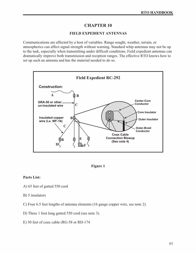
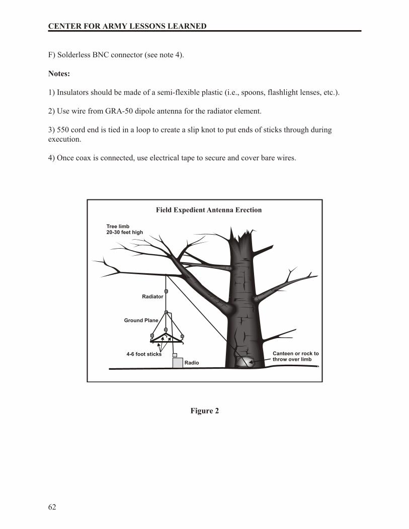
Chapter 10: Field Expedient Antennas 61
Chapter 11: Advanced Systems Improvement Program (ASIP) RadioRanges and Battery Usage
63
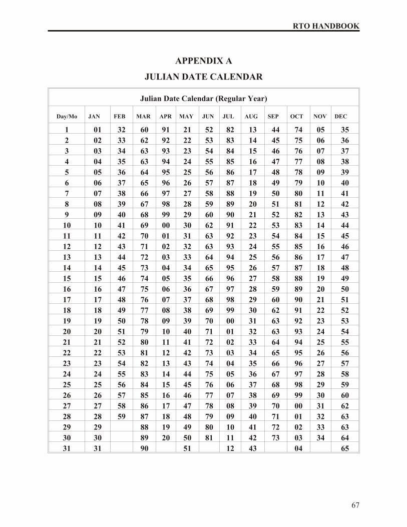
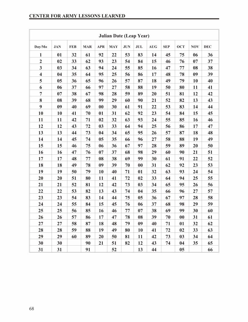
Appendix A: Julian Date Calendar 67
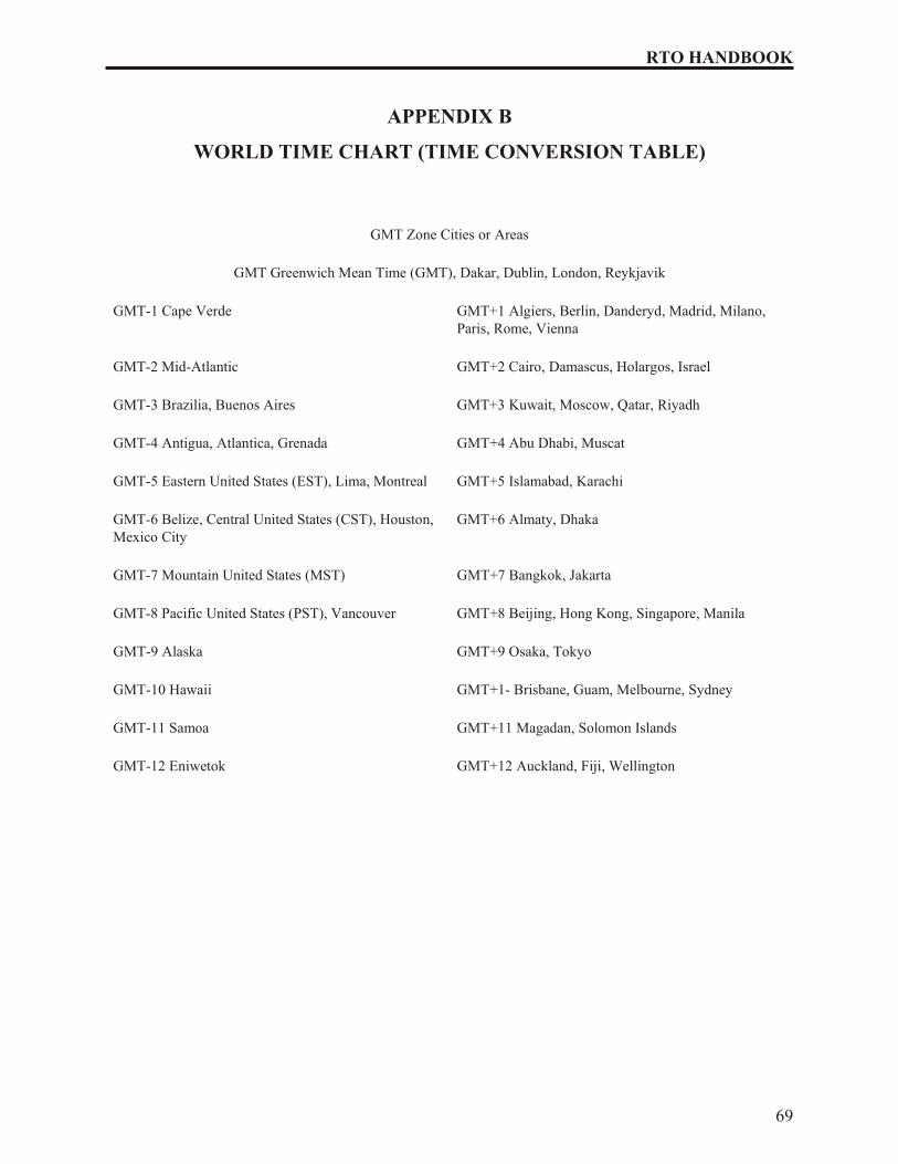
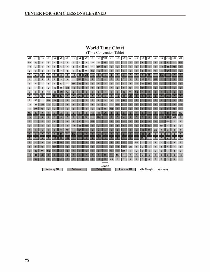
Appendix B: World Time Chart (Time Conversion Table) 69
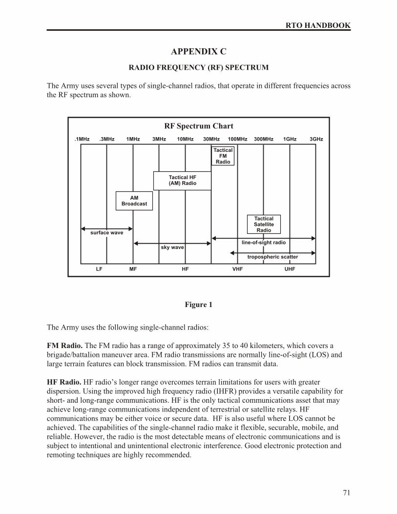
Appendix C: Radio Frequency Spectrum 71
Appendix D: Glossary 73
Conclusion 77
Note: This handbook contains numerous acronyms tailored to RTOprocedures and equipment. Refer to the Glossary for a definition of theacronyms.
i
RTO HANDBOOK
CENTER FOR ARMY LESSONS LEARNED
Director Colonel Michael A. Hiemstra
Managing Editor Mr. George Mordica
Editor, Layout, and Design Valerie Tystad
Graphics and Cover Catherine Elliott
Project Manager/Author Sergeant First Class Robert Ehrlich
Project Analysts Mr. Ralph Nichols
Mr. Tom Odom
The Secretary of the Army has determined that the publication of this periodical isnecessary in the transaction of the public business as required by law of the Department.Use of funds for printing this publication has been approved by Commander, U.S. ArmyTraining and Doctrine Command, IAW AR 25-30.
Unless otherwise stated, whenever the masculine or feminine gender is used, both areintended.
LOCAL REPRODUCTION OF THIS NEWSLETTER IS AUTHORIZED ANDENCOURAGED.
ii
CENTER FOR ARMY LESSONS LEARNED
CHAPTER 1
USER INFORMATION AND REFERENCES
This chapter provides a compendium of basic user information and references necessary for allRTOs. It is not a complete guide to SINCGARS or RTO duties. Rather it is a start point and ahandy reference for any soldier who may be tasked with RTO duties. Because the RTO is thesmall unit leader’s walking, talking tactical operations center, this chapter also provides a similar start point for unit leaders, from team to battalion, who need to be familiar with the SINCGARSand RTO duties.
1. REFERENCES.
a. TM 11-5820-890-10-8, Operators Manual, SINCGARS Ground Combat Net Radio,ICOM.
b. TM 11-5820-890-10-6, SINCGARS ICOM Ground Radios Operator’s Pocket Guide.
c. TM 11-5820-890-10-7, SINCGARS ICOM Ground Radios NCS Pocket Guide.
d. FM 11-32, Combat Net Radio Operations.
e. TM 11-5825-291-13, Satellite Signals Navigation Sets.
f. TB 11-5825-291-10-3, The PLGR Made Simple.
g. TB 380-41 (Change 1), Procedures for Safeguarding, Accounting and SupplyControl of COMSEC Material.
2. PURPOSE. This guide establishes procedures, guidelines, and information on operating theSINCGARS radio system. It is designed to supplement unit level RTO training and certificationand act as a quick reference for RTOs when faced with a communications problem.
3. GENERAL.
a. SINCGARS ASIP is a “user owned and operated” solid-state frequency modulated(FM) combat net radio (CNR), that operates in the 30.000 to 87.995 MHZ frequencyrange in the single channel (SC) or frequency hopping (FH) mode. The ASIP replaces the RT-1523A and RT-1523B model SINCGARS. The ASIP is compatible with the olderSINCGARS and with NATO forces in SC, squelch off mode. It provides electronicwarfare (EW) protection and a reduced electromagnetic signature in the FH mode.
b. The AN/CYZ-10 automated net control device (ANCD) is a hand-held device capableof receiving, storing, and transferring data between ANCDs, or between ANCD and anASIP radio. The primary application for this device is to fill the ASIP with FH data, time, communications security (COMSEC), and loadset information. ANCDs arenon-repairable controlled cryptographic items (CCI) and must be stored IAW TB 340-1(change 1). Loaded ANCD with “Secret” information must be stored in a 3-combinationsafe. ANCDs that are not loaded must be secured with no less than two barrier protection, i.e. a locked door and wall locker using a 200 series lock.
1
RTO HANDBOOK
c. The AN/PSN-11 precision lightweight global positioning system receiver (PLGR) is ahand-held Global Positioning System (GPS). The primary application for this device isprecision position location and land navigation via programmable waypoints. Thesecondary application for this device is to update and verify the date and time in the ASIP radio. The PLGR is a high dollar item and should be safeguarded accordingly.
d. The ASIP and ANCD are CCI and require double-barrier protection IAW DA PAM25-380-2. All unattended ASIP radios will be zeroed. Radios will be reloaded whenrequired using the ANCD.
e. Maintenance procedures are the same for the older SINCGARS radio. The ASIP isaccountable by serial number. When the RT-1523E has been determined non-missioncapable (NMC) by unit-level maintenance personnel, it will be turned in to the forwardsupport battalion (FSB), direct support unit (DSU) for repairs. The DSU will thendetermine if the radio will be replaced or held for repair in the shop. A property booktransaction (lateral transfer) is required should the radio be exchanged for a workingRT-1523F. Only company communications chiefs and/or RTOs will turn-in equipment to the battalion communications section.
4. OPERATING PROCEDURES.
a. Net synchronization time (NET).
(1) The ASIP has an internal master clock. Each channel (1 through 6) also hasthe ability to maintain separate time. Time is primarily loaded into the ASIP viathe ANCD and alternately the PLGR. If the ANCD is used, ensure the time in theANCD has accurate ZULU time stored. GPS ZULU time is the standard timezone used for all division radios.
(2) The ZULU time stored in an ANCD will drift significantly over time and ifloaded into the ASIP will not allow communications with other net members. AllRTOs must verify accurate time in the ASIP after loading their radios. All RTOsmust also maintain accurate time (hour, minute, and seconds) on a digital watch to quickly verify time. Time must be within + or – 4 seconds to communicate withother ASIPs. Accurate ZULU time can be obtained by the following methods:
(c) Top of the hour on any 5 kHz frequency via HF radios (PRC-104).
(3) Julian date (JD). The ASIP JD is the last two digits of the full Julian date. SeeAppendix A (Julian date calendar) for the correct Julian date. The JD is alsoautomatically loaded via the ANCD. If a net member loads the incorrect JD oraccidentally changes the JD, all communications with other net members will belost.
(4) During FH operations, the net control station (NCS) will always maintainaccurate time and will operate a radio in the frequency hop master (FH-M) mode.The NCS for each net is the only radio authorized to operate in the FH-M mode.This will ensure time accuracy throughout the net. Should the NCS radio fail
2
CENTER FOR ARMY LESSONS LEARNED
during any part of the mission, the alternate NCS will switch his radio to theFH-M mode.
b. Initial net opening. The battalion standard is Hot Start net opening procedure. Theprocedure is covered in Chapter 3 (Operator Tasks).
c. Passive late net entry. This procedure allows a radio with correct hop set andCOMSEC information but inaccurate time (+ or – 59 seconds) to enter a net. Theprocedures are covered in Chapter 3 (Operator Tasks).
d. Loadset.
(1) Loadsets are made up of the following components:
(a) TranSec key (TSK) – frequency hop data
(b) Esets – net IDs (example F302)
(c) COMSEC keys (TEK and KEK) – transmission encryption keys
(d) Lockout sets – restricted frequencies within the frequency hop data.
(2) The ANCD transfers a loadset to an ASIP radio. This loadset is transferred bya menu-driven procedure during normal loading procedures of the ASIP with theANCD.
(3) Net IDs are normally fixed and will follow the numbering scheme listedbelow. Specific net IDs within the below listed ranges are designated in the signal operating instructions (SOI).
Note: These are sample division standards only and may change for realworld contingencies or deployments
FH000-099 Theater/Joint
FH100-299 Corps/Service
FH300-399 (1st BDE)
FH400-499 (2nd BDE)
FH500-599 (3rd BDE)
FH600-699 (AVN BDE)
FH700-799 (DIVARTY)
FH800-899 (DISCOM)
FH900-999 (DIV HQs)
e. Operational security (OPSEC). OPSEC is defined as any measure an operator takes inorder to safeguard information from the enemy. OPSEC can be anything from
3
RTO HANDBOOK
minimizing the number of net IDs loaded into a radio, to zeroing an ANCD or radio ifcapture by the enemy is imminent, thereby denying the enemy the ability to exploit theANCD or radio for intelligence against U.S. Forces. All personnel assigned to, attachedto, or under the operational control of the battalion will follow these procedures tomaximize OPSEC.
(1) Loadsets contain only the primary net used by the operator. If the RTOrequires additional nets he will manually load the ASIP with the required net.Minimize the number of channels used.
(2) ANCDs only contain the loadset and COMSEC required by the operator.
(3) New editions of the signal operating instructions (SOI) and COMSEC shouldnot be distributed below the battalion level until authorized by the brigade signalofficer (SIGO).
(4) All RTOs must know all compromise procedures and codewords prescribed in Chapter 2 (Compromise Procedures) and understand the steps for eachprocedure.
(5) Safeguard any radio cheat sheets that list call signs and net IDs and accountfor cheat sheets according to classification (for official use only [FOUO],classified, secret, etc.). Whenever possible, memorize this information.
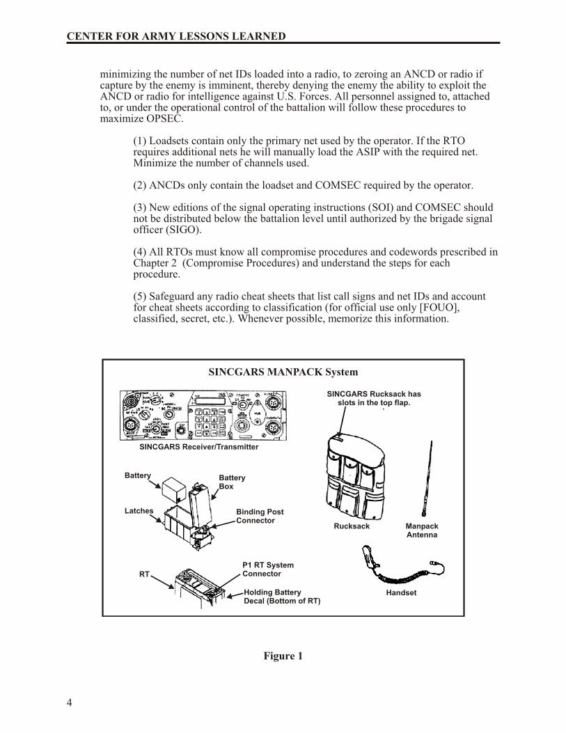
Figure 1
4
CENTER FOR ARMY LESSONS LEARNED
SINCGARS Receiver/Transmitter
SINCGARS Rucksack hasslots in the top flap.
Rucksack ManpackAntenna
Handset
BatteryBox
Binding PostConnector
P1 RT SystemConnector
Holding BatteryDecal (Bottom of RT)
Battery
Latches
RT
SINCGARS MANPACK System
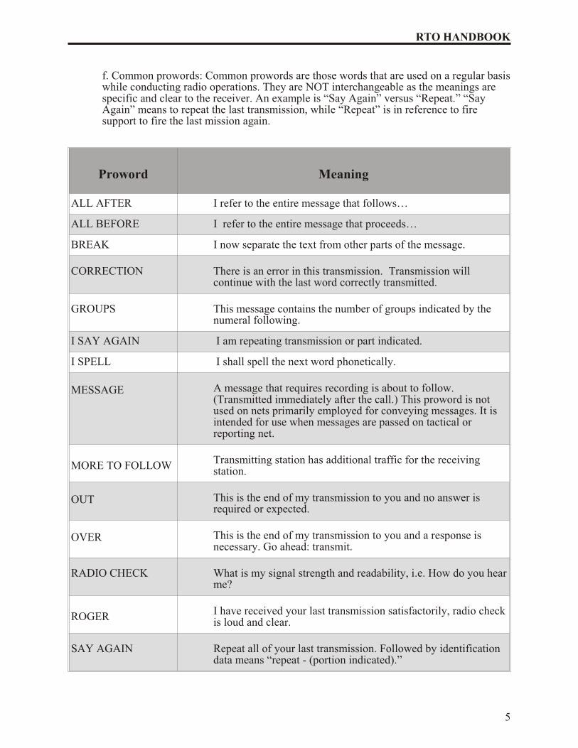
f. Common prowords: Common prowords are those words that are used on a regular basis while conducting radio operations. They are NOT interchangeable as the meanings arespecific and clear to the receiver. An example is “Say Again” versus “Repeat.” “SayAgain” means to repeat the last transmission, while “Repeat” is in reference to firesupport to fire the last mission again.
Proword Meaning
ALL AFTER I refer to the entire message that follows…
ALL BEFORE I refer to the entire message that proceeds…
BREAK I now separate the text from other parts of the message.
CORRECTION There is an error in this transmission. Transmission willcontinue with the last word correctly transmitted.
GROUPS This message contains the number of groups indicated by thenumeral following.
I SAY AGAIN I am repeating transmission or part indicated.
I SPELL I shall spell the next word phonetically.
MESSAGE A message that requires recording is about to follow. (Transmitted immediately after the call.) This proword is notused on nets primarily employed for conveying messages. It isintended for use when messages are passed on tactical orreporting net.
MORE TO FOLLOW Transmitting station has additional traffic for the receivingstation.
OUT This is the end of my transmission to you and no answer isrequired or expected.
OVER This is the end of my transmission to you and a response isnecessary. Go ahead: transmit.
RADIO CHECK What is my signal strength and readability, i.e. How do you hear me?
ROGER I have received your last transmission satisfactorily, radio check is loud and clear.
SAY AGAIN Repeat all of your last transmission. Followed by identificationdata means “repeat - (portion indicated).”
5
RTO HANDBOOK
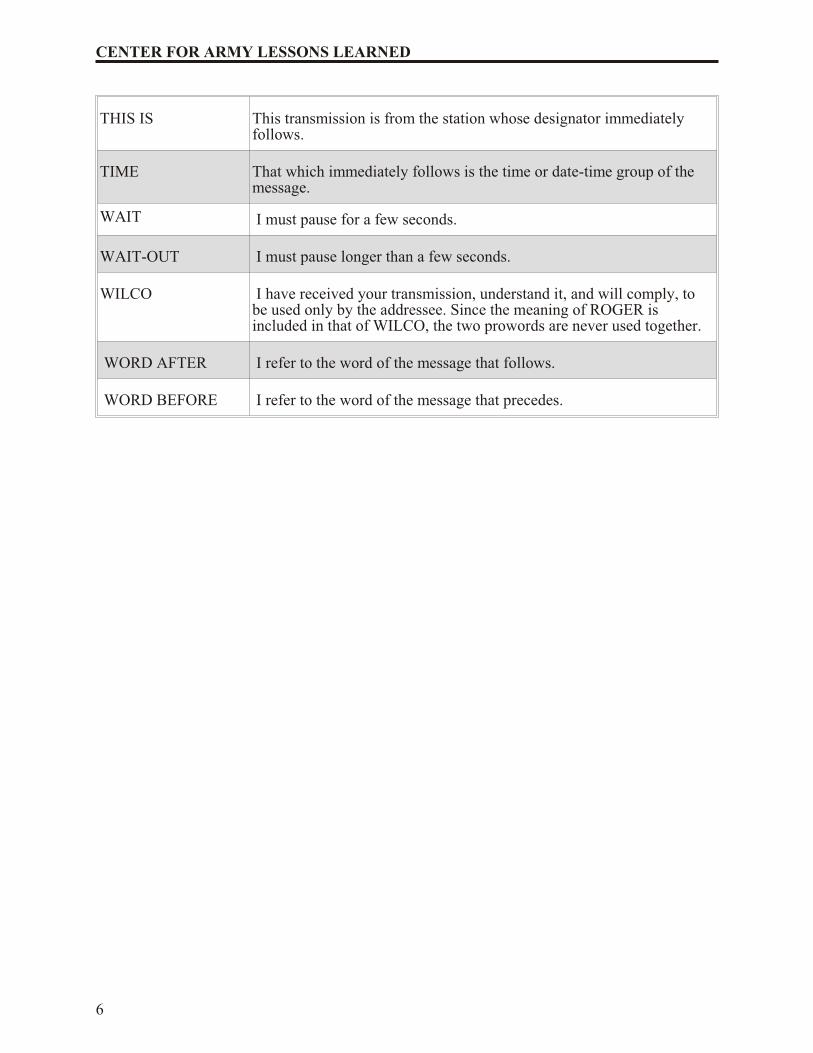
THIS IS This transmission is from the station whose designator immediatelyfollows.
TIME That which immediately follows is the time or date-time group of themessage.
WAIT I must pause for a few seconds.
WAIT-OUT I must pause longer than a few seconds.
WILCO I have received your transmission, understand it, and will comply, tobe used only by the addressee. Since the meaning of ROGER isincluded in that of WILCO, the two prowords are never used together.
WORD AFTER I refer to the word of the message that follows.
WORD BEFORE I refer to the word of the message that precedes.
6
CENTER FOR ARMY LESSONS LEARNED
CHAPTER 2
COMPROMISE PROCEDURES
Compromise of sensitive signal information, like death and taxes, is inevitable and alwaysunwelcome. Still the effects of compromise can be minimized through common senseprecautions and standardized corrective measures embedded in unit SOPs. The operative word in dealing with compromise is a common understanding of those procedures based on repetitivedrills. This chapter offers a possible template for units in establishing compromise procedures.But remember like all such standardized procedures, this SOP is absolutely worthless if notpracticed and understood by all in a unit.
1. PURPOSE. This chapter establishes procedures, guidelines, and information on compromiseprocedures. It is designed to standardize the process for executing compromise procedures. Thecompromise procedures reflect the steps used by the division and brigade.
2. GENERAL. A compromise is defined as any COMSEC fill device or COMSEC-filled andfunctioning radio that falls into enemy hands before the operator can zero the device. Theprocedures listed below detail actions to take to minimize compromises, actions to take if acompromise is imminent, and actions to take after a net becomes compromised.
3. PROCEDURES.
a. Minimizing compromise
(1) ANCDs are not distributed below the infantry company headquarters or below antitank platoon headquarters level. Combat multipliers will not deploy withANCDs and will receive all radio fills from the maneuver element they aresupporting. Ensure all CCI is properly accounted for and secured at all times.
(2) Signal operation instructions (SOI) data is not distributed below battalionlevel. The new challenge and password is announced over a secure command netdaily at 0001 hours (ZULU).
(3) All command vehicles leaving the tactical operation center (TOC) orheadquarters command post secure their ANCDs at that TOC or command post(CP).
(4) Excess ANCDs within a deployed unit are zeroed.
b. If compromise is imminent
(1) If carrying an ANCD, the operator immediately zeroes the ANCD by hittingthe red zero key four times, then removes the COMSEC encryption key (CIK)and destroys it. By destroying the ANCD’s CIK, the ANCD is inoperable.
(2) Operators announce on the radio, “ALL STATIONS THIS NET, THIS IS(call sign) WATERGATE, WATERGATE, WATERGATE!” and thenimmediately zero the COMSEC by turning the function knob to “Z.” Thismessage alerts other net members that you have zeroed your radio’s COMSEC
7
RTO HANDBOOK
because you are being captured. You may still use the radio, but only in anon-secure mode, until you can receive another ANCD fill.
c. After a compromise
(1) If you suspect a net is compromised DO NOT announce over the net, “THISNET IS COMPROMISED!” Use an alternate secure net to notify your higherheadquarters and/or announce over the net, “ALL STATIONS THIS NET, THISIS (call sign) RED EYE, RED EYE, RED EYE!” This message alerts other netmembers that you suspect the net is compromised and all classified traffic mustcome to a halt.
(2) Compromised nets continue to operate on the compromised traffic encryptionkey (TEK) until the net control station (NCS) directs a change of the TEK or netID. The directive will only come from the battalion signal officer.
(3) Once the mission allows, the NCS directs a net ID or TEK change using thefollowing codewords:
Net ID
RATTLESNAKE 1: Change to STRIKE NET 1
RATTLESNAKE 2: Change to STRIKE NET 2
RATTLESNAKE 3: Change to original NET ID
An alternate method is to change the Julian date (JD) on the radio net usingcodewords and leaving the net ID alone. Example:
Julian Date
WARRIOR SPIRIT 1: Change JD + 3
WARRIOR SPIRIT 2: Change JD + 5
WARRIOR SPIRIT 3: Change JD + 7
(4) The NCS directs over-the-air-rekey (OTAR) using either the automatic remote keying (AK) method or manual remote keying (MK) method. The procedures forboth tasks are covered in Chapter 4 (NCS Tasks). Once either method is executed, the NCS makes a radio check with all net members. An alternate NCS acts as a“sweeper” and remains on the old net ID or TEK until all members are notifiedand comply with the change.
(5) Actual STRIKE net IDs are found in the SOI and must be memorized.STRIKE net IDs WILL NOT BE WRITTEN DOWN ANYWHERE.
(6) Once the new net is established, it is clear for classified traffic again.
8
CENTER FOR ARMY LESSONS LEARNED
(7) Codewords used to initiate change of SOI editions are as follows:
SOI
COBRA: Change to B edition TEK/SOI
PYTHON: Change to C edition TEK/SOI
COTTONMOUTH: Change to original TEK/SOI
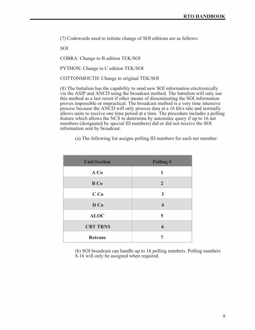
(8) The battalion has the capability to send new SOI information electronicallyvia the ASIP and ANCD using the broadcast method. The battalion will only usethis method as a last resort if other means of disseminating the SOI informationproves impossible or impractical. The broadcast method is a very time intensiveprocess because the ANCD will only process data at a 16 kb/s rate and normallyallows units to receive one time period at a time. The procedure includes a polling feature which allows the NCS to determine by automatic query if up to 16 netmembers (designated by special ID numbers) did or did not receive the SOIinformation sent by broadcast.
(a) The following list assigns polling ID numbers for each net member:
Unit/Section Polling #
A Co 1
B Co 2
C Co 3
D Co 4
ALOC 5
CBT TRNS 6
Retrans 7
(b) SOI broadcast can handle up to 16 polling numbers. Polling numbers8-16 will only be assigned when required.
9
RTO HANDBOOK
CHAPTER 3
OPERATOR TASKS
The RTO, like any other soldier, has a standard set of tasks to accomplish in training and actualoperations. For the practiced RTO, such tasks become almost second nature, especially thosetasks that are daily requirements. On occasion even an experienced operator may need to refreshhis/her memory when a less practiced requirement pops up. For less experienced RTOs, the need for a standard list of tasks is self-evident. This chapter offers all RTOs, both experienced andnovice, a standard list of tasks and a quick guide on how they are accomplished.
PURPOSE. To provide operators of ASIP radios with a quick reference to assist in taskperformance during training and operations. Using this RTO handbook, the properly trainedASIP operator should be able to perform, without assistance, all operator tasks.
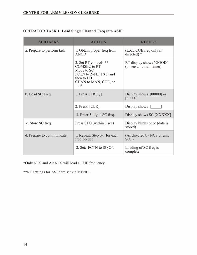
Task 1 (Load SC Frequency into ASIP): The ASIP operator is required to perform thistask in preparation for the employment of single channel communications, use of theCUE (key the radio) and ERF (electronic remote fill) methods of late net entry, and forsingle channel frequency updates. The operator determines the required frequencies fromthe ANCD or another source. These frequencies are then loaded into the radio by use ofthe receiver-transmitter (RT) keyboard.
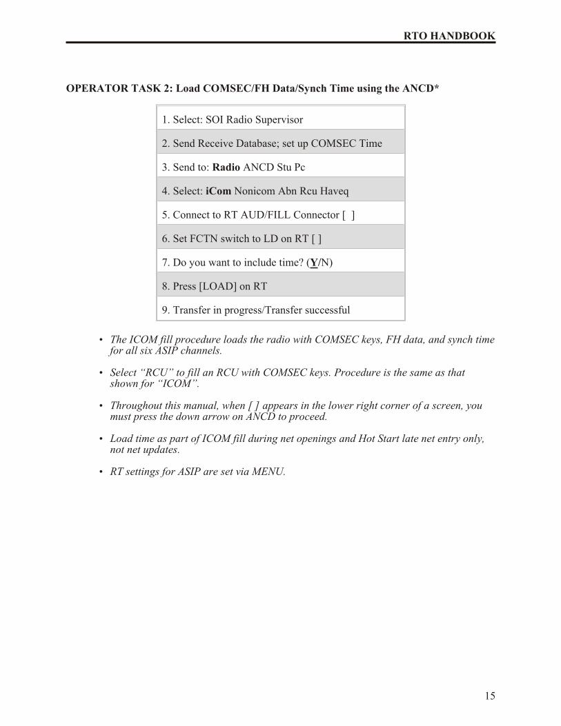
Task 2 (Load COMSEC/FH Data/Sync Time using the ANCD): This task is requiredin preparation for a Hot Start net opening and, without sync time, for COMSEC/FH dataupdates. Performance of this task involves the use of an ANCD as a source of COMSECkeys, FH data (hopset, TSK, and net ID), and sync time. By use of the ICOM fillprocedure, COMSEC, FH data, and sync time are simultaneously loaded into all sixchannels of the ASIP radio. Upon completion of the ICOM fill, the radio is fully prepared for secure, frequency hopping communications.
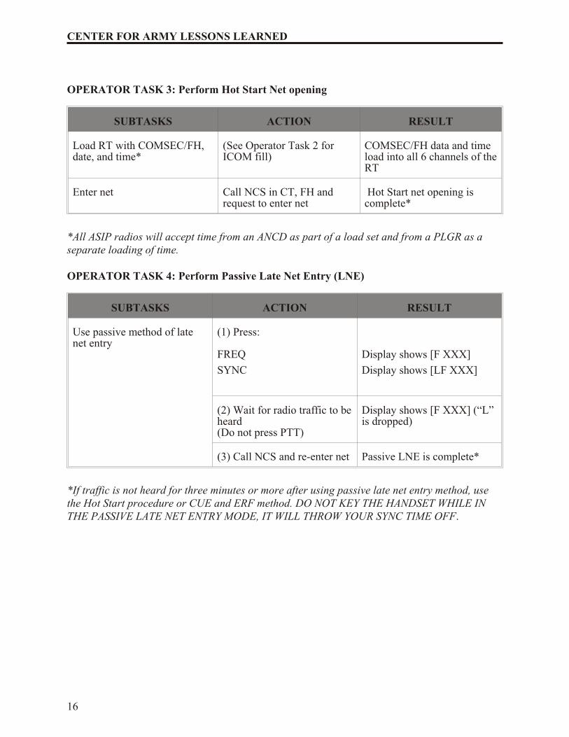
Task 3 (Perform Hot Start Net Opening): This task is required when the net has beendown for any reason and is to become operational at a prescribed time. This task involves loading the radio with COMSEC keys, FH data, and sync time by use of the ICOM fillprocedure (See Operator Task 2) and calling the NCS in secure frequency hopping modeto request net entry.
Task 4 (Perform Passive Late Net Entry): This task is required when the sync time inyour radio becomes more than 4 seconds (plus or minus), but less than one minute,different from net sync time. Passive late net entry enables an individual operator tore-enter the net without action on the part of the NCS or other net operators. This taskmakes use of a feature built into the ASIP radio and involves two steps: placing the RT in passive late net entry mode and waiting for the radio to adjust its sync time to that of thenet. When this method of late net entry does not work, the Hot Start procedure or CUEand ERF method of late net entry should be used.
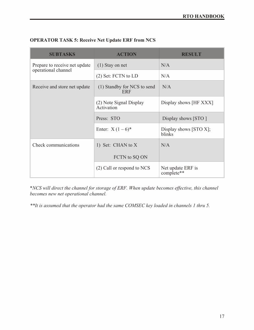
Task 5 (Receive Net Update ERF from NCS): This task is performed when there is arequirement to change or update some element of FH data and the operational situationmakes it impossible or impractical to disseminate the new data by physical connection ofANCD to ANCD. In such cases, the NCS alerts net operators that they are to receive anet update ERF. Operators then change the RT FCTN from SQ ON to LD, remaining onthe operational channel. The NCS sends the ERF on the operational channel (not on
11
RTO HANDBOOK
MAN as during a Cold Start net opening). Once the net update ERF has been sent, thenew data may be made effective immediately or stored for later implementation. (ERF,broadcast, and OTAR communications).
Task 6 (Perform CUE and ERF Late Net Entry (LNE): This task may be requiredwhen a radio has been out of the net for some period or has lost its sync time. Thepreferred action is to try passive late net entry first (See Operator Task 4). This methodrequires the operator to load CUE and MAN frequencies, “cue” the NCS in plain text(PT), repeat the “cue” until a response is received, switch COMSEC to cipher text (CT)to receive the NCS response, use single channel mode, and receive and store an ERFwhen it is sent. (A simpler method of re-entering the net when the passive method doesnot work is the Hot Start procedures (See Operator Task 3).
Task 7 (Change Net ID): This operator task is performed when there is a requirement tocommunicate with a net or station that is not a part of the operational loadset or loadsets,if more than one radio is being used. Commanders, staff officers, drivers, and others whofrequently move about the battlefield should be able to perform this task withoutassistance. Use of this procedure enables the operator to contact virtually anySINCGARS net within division.
12
CENTER FOR ARMY LESSONS LEARNED
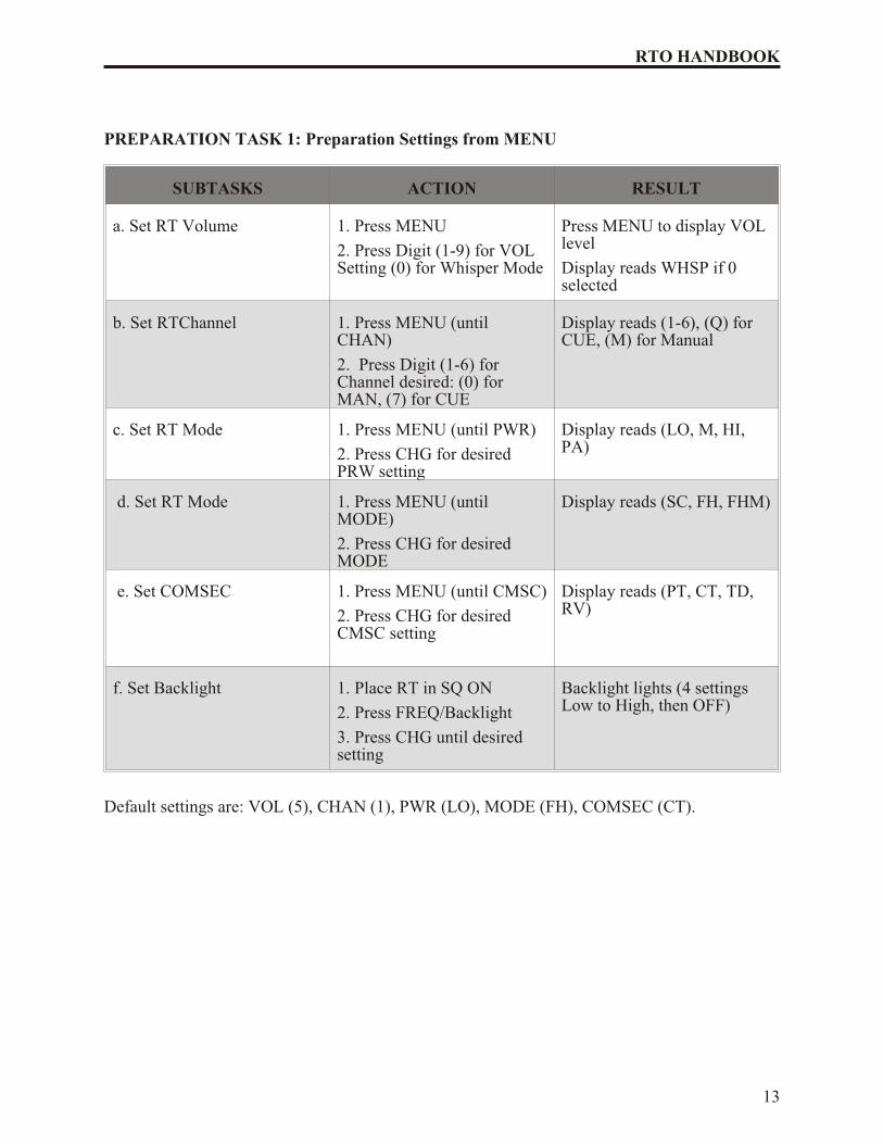
PREPARATION TASK 1: Preparation Settings from MENU
SUBTASKS ACTION RESULT
a. Set RT Volume 1. Press MENU
2. Press Digit (1-9) for VOLSetting (0) for Whisper Mode
3. Enter 5-digits SC freq. Display shows SC [XXXXX]
c. Store SC freq. Press STO (within 7 sec) Display blinks once (data isstored)
d. Prepare to communicate 1. Repeat: Step b-1 for eachfreq needed
(As directed by NCS or unitSOP)
2. Set: FCTN to SQ ON Loading of SC freq iscomplete
*Only NCS and Alt NCS will load a CUE frequency.
**RT settings for ASIP are set via MENU.
14
CENTER FOR ARMY LESSONS LEARNED
OPERATOR TASK 2: Load COMSEC/FH Data/Synch Time using the ANCD*
1. Select: SOI Radio Supervisor
2. Send Receive Database; set up COMSEC Time
3. Send to: Radio ANCD Stu Pc
4. Select: iCom Nonicom Abn Rcu Haveq
5. Connect to RT AUD/FILL Connector [ ]
6. Set FCTN switch to LD on RT [ ]
7. Do you want to include time? (Y/N)
8. Press [LOAD] on RT
9. Transfer in progress/Transfer successful
• The ICOM fill procedure loads the radio with COMSEC keys, FH data, and synch time for all six ASIP channels.
• Select “RCU” to fill an RCU with COMSEC keys. Procedure is the same as thatshown for “ICOM”.
• Throughout this manual, when [ ] appears in the lower right corner of a screen, youmust press the down arrow on ANCD to proceed.
• Load time as part of ICOM fill during net openings and Hot Start late net entry only,not net updates.
• RT settings for ASIP are set via MENU.
15
RTO HANDBOOK
OPERATOR TASK 3: Perform Hot Start Net opening
SUBTASKS ACTION RESULT
Load RT with COMSEC/FH,date, and time*
(See Operator Task 2 forICOM fill)
COMSEC/FH data and timeload into all 6 channels of the RT
Enter net Call NCS in CT, FH andrequest to enter net
Hot Start net opening iscomplete*
*All ASIP radios will accept time from an ANCD as part of a load set and from a PLGR as aseparate loading of time.
OPERATOR TASK 4: Perform Passive Late Net Entry (LNE)
SUBTASKS ACTION RESULT
Use passive method of latenet entry
(1) Press:
FREQ
SYNC
Display shows [F XXX]
Display shows [LF XXX]
(2) Wait for radio traffic to be heard (Do not press PTT)
Display shows [F XXX] (“L”is dropped)
(3) Call NCS and re-enter net Passive LNE is complete*
*If traffic is not heard for three minutes or more after using passive late net entry method, usethe Hot Start procedure or CUE and ERF method. DO NOT KEY THE HANDSET WHILE INTHE PASSIVE LATE NET ENTRY MODE, IT WILL THROW YOUR SYNC TIME OFF.
16
CENTER FOR ARMY LESSONS LEARNED
OPERATOR TASK 5: Receive Net Update ERF from NCS
SUBTASKS ACTION RESULT
Prepare to receive net updateoperational channel
(1) Stay on net N/A
(2) Set: FCTN to LD N/A
Receive and store net update (1) Standby for NCS to sendERF
N/A
(2) Note Signal DisplayActivation
Display shows [HF XXX]
Press: STO Display shows [STO ]
Enter: X (1 – 6)* Display shows [STO X];blinks
Check communications 1) Set: CHAN to X
FCTN to SQ ON
N/A
(2) Call or respond to NCS Net update ERF iscomplete**
*NCS will direct the channel for storage of ERF. When update becomes effective, this channelbecomes new net operational channel.
**It is assumed that the operator had the same COMSEC key loaded in channels 1 thru 5.
17
RTO HANDBOOK
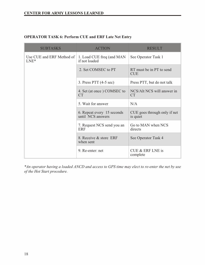
OPERATOR TASK 6: Perform CUE and ERF Late Net Entry
SUBTASKS ACTION RESULT
Use CUE and ERF Method of LNE*
1. Load CUE freq (and MANif not loaded
See Operator Task 1
2. Set COMSEC to PT RT must be in PT to sendCUE
3. Press PTT (4-5 sec) Press PTT, but do not talk
4. Set (at once ) COMSEC toCT
NCS/Alt NCS will answer inCT
5. Wait for answer N/A
6. Repeat every 15 secondsuntil NCS answers
CUE goes through only if netis quiet
7. Request NCS send you anERF
Go to MAN when NCSdirects
8. Receive & store ERFwhen sent
See Operator Task 4
9. Re-enter: net CUE & ERF LNE iscomplete
*An operator having a loaded ANCD and access to GPS time may elect to re-enter the net by use of the Hot Start procedure.
18
CENTER FOR ARMY LESSONS LEARNED
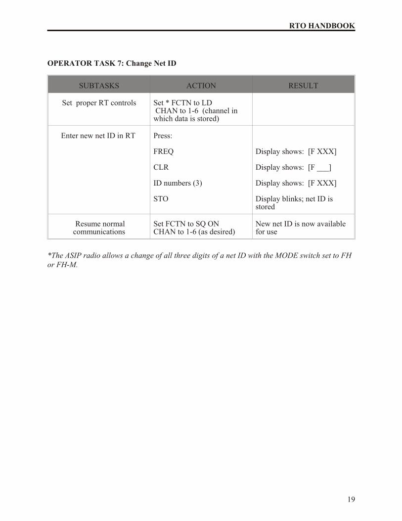
OPERATOR TASK 7: Change Net ID
SUBTASKS ACTION RESULT
Set proper RT controls Set * FCTN to LD CHAN to 1-6 (channel inwhich data is stored)
Enter new net ID in RT Press:
FREQ
CLR
ID numbers (3)
STO
Display shows: [F XXX]
Display shows: [F ___]
Display shows: [F XXX]
Display blinks; net ID isstored
Resume normalcommunications
Set FCTN to SQ ONCHAN to 1-6 (as desired)
New net ID is now availablefor use
*The ASIP radio allows a change of all three digits of a net ID with the MODE switch set to FHor FH-M.
19
RTO HANDBOOK
CHAPTER 4
NET CONTROL STATION (NCS) TASKS
Without an effective net control station, a radio net will degenerate rapidly into chaos under thestress of training. Actual combat only accelerates that process. It is up to NCS to maintain netprocedures and discipline. As in the case with operator tasks, the experienced NCS will know the routine tasks and be able to perform them without hesitation. For non-routine tasks, the standardtask list provided here should help. Novice NCS personnel will also find this list and “how to”guide useful.
PURPOSE. To provide net control station (NCS) personnel with quick reference to assist in taskperformance during training and operations. Using this RTO Handbook, properly trained NCSpersonnel should be able to perform, without assistance, all NCS tasks.
Task 1 (Conduct Hot Start Net Opening): This task represents a basic NCSrequirement, to open the SINCGARS secure, frequency hopping net. During use of theHot Start net opening procedure, NCS responsibilities are primarily supervisory. Eachoperator loads the radio with COMSEC keys, FH data, and sync time in preparation forthe net opening. Upon completing the ICOM fill, the operator merely calls the NCS insecure, FH mode and requests permission to enter the net. NCS requirements are limitedto ensuring that operations are provided the required data for net opening and respond tooperator requests for net entry.
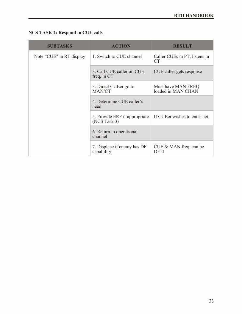
Task 2 (Respond to CUE Calls): An important feature of the SINCGARS radio is itsability to be contacted by a non-frequency hopping radio, or an HF radio lacking data orsync time, through a process known as “CUEing.” To CUE, set the calling radio on theprescribed CUE frequency, press the push-to-talk switch, and wait for a response. Thisaction causes a “CUE” message to appear in the RT display of the NCS and alternateNCS radio.
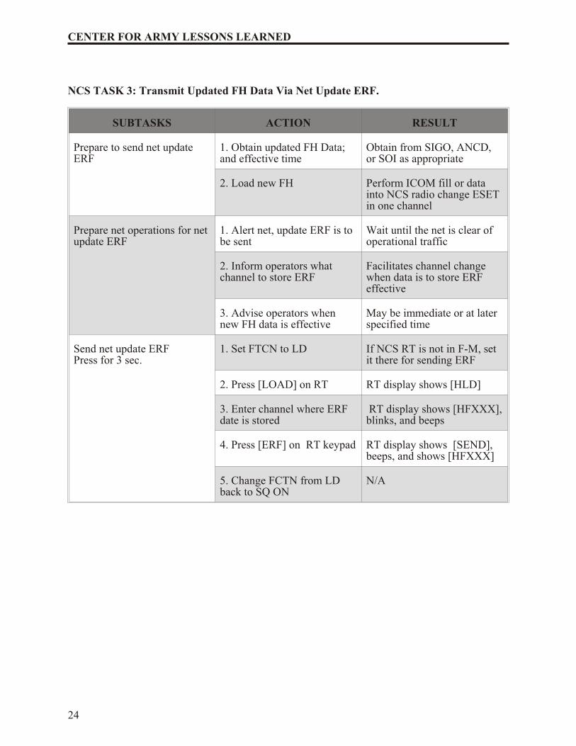
Task 3 (Transmit Updated FH Data Via Net Update ERF): This task enables theNCS to electronically transmit new FH data to net operators when distribution byphysical connection of ANCD to ANCD is impossible or impractical. This proceduremay be used to update (change) hopsets, TSKs, net Ids, and sync time. The task involvesalerting net operators, sending the ERF using the net operational channel, confirmingreceipt of the ERF, and making a communications check when the changed FH data isput into effect.
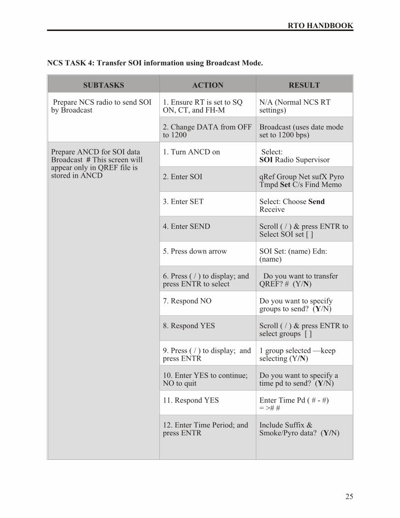
Task 4 (Transfer SOI Information Using Broadcast Mode): This procedure enablesan NCS to send SOI information electronically to net members wherever updating byphysical connection of ANCD to ANCD proves to be impossible or impractical. TheBroadcast mode requires approximately two minutes to transmit one time period of abattalion SOI extract. The procedure includes a polling feature that allows the NCS todetermine by automatic query if up to 16 net operators (designated by special IDnumbers) did or did not receive the SOI information sent by Broadcast mode.
Task 5 (Send TEK to other NCSs Using MK Method of OTAR): This procedureallows an NCS to transfer a TEK (not a KEK) electronically, over-the-air-rekey (OTAR)to other NCSs. This capability is useful when the tactical situation or terrain makes itimpossible or impractical to pass new TEK by physical connection of ANCD to ANCD.
21
RTO HANDBOOK
Receiving NCSs store the new TEK in their ANCDs. The new TEK can then be passedto operators by physical transfer. NCS Tasks 5 and 7 are performed together by Sourceand Target NCSs, respectively.
Task 6 (Receive and Store TEK Sent by MK Method OTAR): This task is performed by target NCSs when a source NCS electronically transmits a TEK using the MK method of OTAR. This procedure allows target NCSs to store the new TEK in their ANCDs forphysical distribution to net operators when required. The sending NCS directs receivingNCSs to perform this task as an integral part of the MK OTAR process. This tasksupplements NCS Task 5 above.
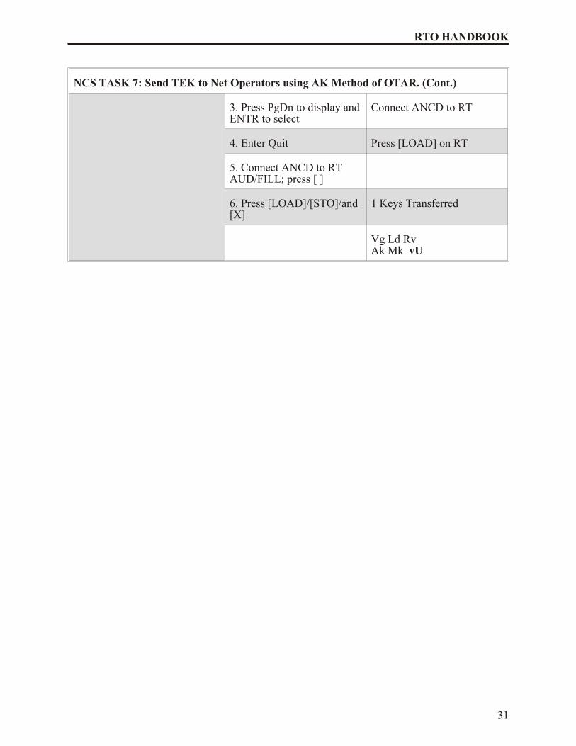
Task 7 (Send TEK to Net Operators Using the AK Method of OTAR): Thisprocedure enables an NCS to transfer electronically a TEK (not a KEK) directly from theNCS ANCD to net member radios. In the AK method, the TEK transferred to netmember radios automatically, and instantaneously replaces the TEK being used. Also,the KEK in the net member radio is automatically updated (changed) during the AKprocedure. After sending a TEK by AK OTAR, the source NCS must load the new TEK.While the AK method of OTAR requires no action on the part of the receiving netmembers, it is quite demanding of the source NCS.
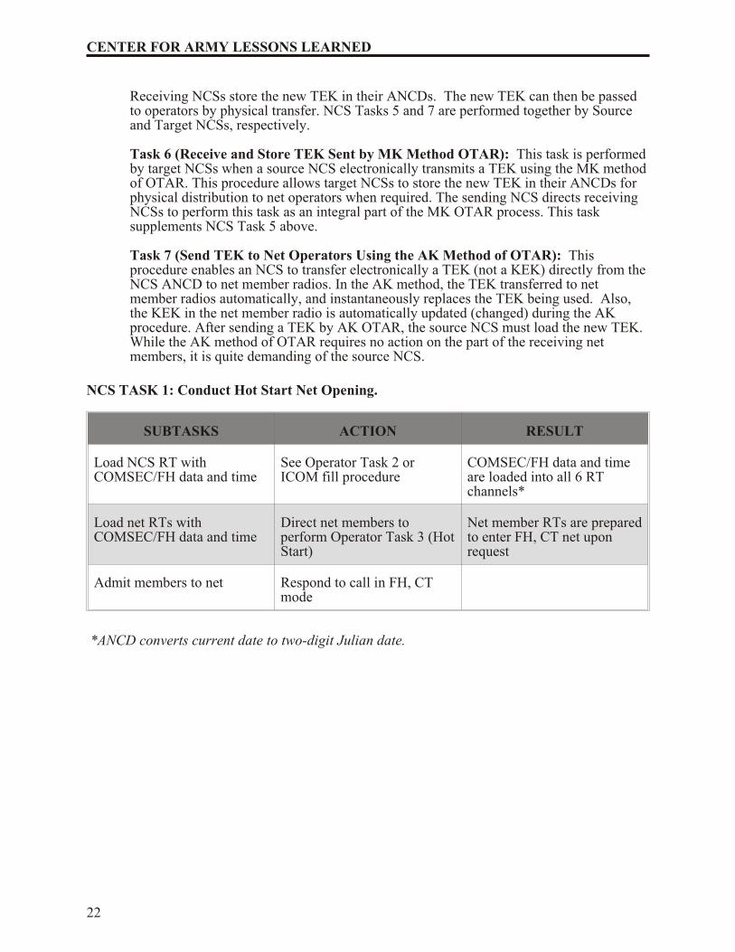
NCS TASK 1: Conduct Hot Start Net Opening.
SUBTASKS ACTION RESULT
Load NCS RT withCOMSEC/FH data and time
See Operator Task 2 orICOM fill procedure
COMSEC/FH data and timeare loaded into all 6 RTchannels*
Load net RTs withCOMSEC/FH data and time
Direct net members toperform Operator Task 3 (Hot Start)
Net member RTs are prepared to enter FH, CT net uponrequest
Admit members to net Respond to call in FH, CTmode
*ANCD converts current date to two-digit Julian date.
22
CENTER FOR ARMY LESSONS LEARNED
NCS TASK 2: Respond to CUE calls.
SUBTASKS ACTION RESULT
Note “CUE" in RT display 1. Switch to CUE channel Caller CUEs in PT, listens inCT
3. Call CUE caller on CUEfreq, in CT
CUE caller gets response
3. Direct CUEer go toMAN/CT
Must have MAN FREQ loaded in MAN CHAN
4. Determine CUE caller’sneed
5. Provide ERF if appropriate (NCS Task 3)
If CUEer wishes to enter net
6. Return to operationalchannel
7. Displace if enemy has DFcapability
CUE & MAN freq. can beDF’d
23
RTO HANDBOOK
NCS TASK 3: Transmit Updated FH Data Via Net Update ERF.
SUBTASKS ACTION RESULT
Prepare to send net updateERF
1. Obtain updated FH Data;and effective time
Obtain from SIGO, ANCD,or SOI as appropriate
2. Load new FH Perform ICOM fill or datainto NCS radio change ESETin one channel
Prepare net operations for netupdate ERF
1. Alert net, update ERF is tobe sent
Wait until the net is clear ofoperational traffic
2. Inform operators whatchannel to store ERF
Facilitates channel changewhen data is to store ERFeffective
3. Advise operators whennew FH data is effective
May be immediate or at laterspecified time
Send net update ERFPress for 3 sec.
1. Set FTCN to LD If NCS RT is not in F-M, setit there for sending ERF
2. Press [LOAD] on RT RT display shows [HLD]
3. Enter channel where ERFdate is stored
RT display shows [HFXXX], blinks, and beeps
4. Press [ERF] on RT keypad RT display shows [SEND],beeps, and shows [HFXXX]
5. Change FCTN from LDback to SQ ON
N/A
24
CENTER FOR ARMY LESSONS LEARNED
NCS TASK 4: Transfer SOI information using Broadcast Mode.
SUBTASKS ACTION RESULT
Prepare NCS radio to send SOIby Broadcast
1. Ensure RT is set to SQON, CT, and FH-M
N/A (Normal NCS RTsettings)
2. Change DATA from OFF to 1200
Broadcast (uses date modeset to 1200 bps)
Prepare ANCD for SOI dataBroadcast # This screen will appear only in QREF file isstored in ANCD
1. Turn ANCD on Select: SOI Radio Supervisor
2. Enter SOI qRef Group Net sufX PyroTmpd Set C/s Find Memo
3. Enter SET Select: Choose SendReceive
4. Enter SEND Scroll ( / ) & press ENTR to Select SOI set [ ]
5. Press down arrow SOI Set: (name) Edn: (name)
6. Press ( / ) to display; andpress ENTR to select
Do you want to transferQREF? # (Y/N)
7. Respond NO Do you want to specifygroups to send? (Y/N)
8. Respond YES Scroll ( / ) & press ENTR to select groups [ ]
9. Press ( / ) to display; and press ENTR
1 group selected —keepselecting (Y/N)
10. Enter YES to continue;NO to quit
Do you want to specify atime pd to send? (Y/N)
11. Respond YES Enter Time Pd ( # - #) = ># #
12. Enter Time Period; andpress ENTR
Include Suffix &Smoke/Pyro data? (Y/N)
25
RTO HANDBOOK
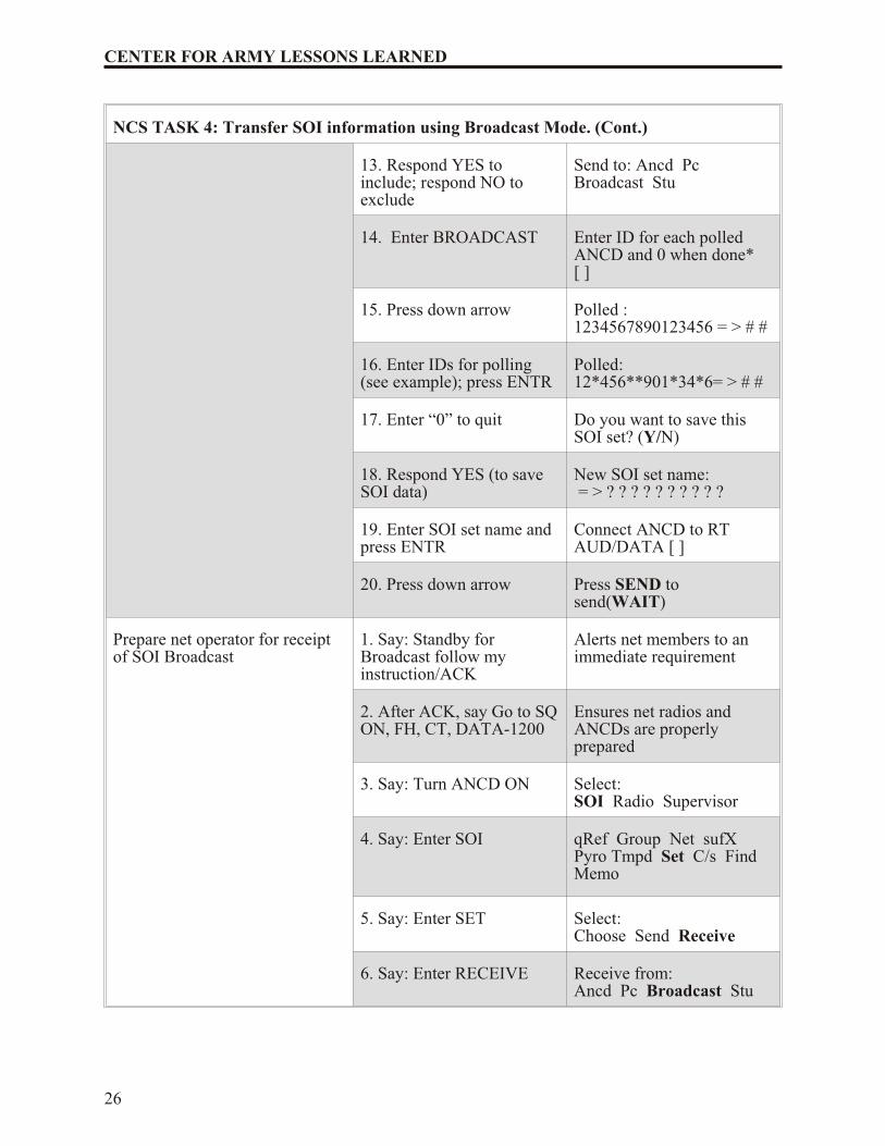
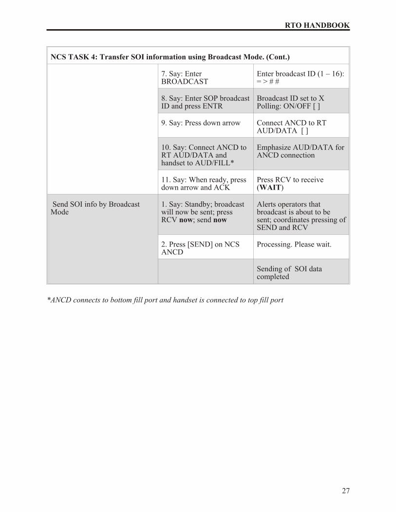
NCS TASK 4: Transfer SOI information using Broadcast Mode. (Cont.)
13. Respond YES toinclude; respond NO toexclude
Send to: Ancd Pc Broadcast Stu
14. Enter BROADCAST Enter ID for each polledANCD and 0 when done* [ ]
15. Press down arrow Polled :1234567890123456 = > # #
16. Enter IDs for polling(see example); press ENTR
Polled:12*456**901*34*6= > # #
17. Enter “0” to quit Do you want to save thisSOI set? (Y/N)
4. Say: Enter SOI qRef Group Net sufX Pyro Tmpd Set C/s Find Memo
5. Say: Enter SET Select:Choose Send Receive
6. Say: Enter RECEIVE Receive from:Ancd Pc Broadcast Stu
26
CENTER FOR ARMY LESSONS LEARNED
NCS TASK 4: Transfer SOI information using Broadcast Mode. (Cont.)
7. Say: EnterBROADCAST
Enter broadcast ID (1 – 16): = > # #
8. Say: Enter SOP broadcast ID and press ENTR
Broadcast ID set to XPolling: ON/OFF [ ]
9. Say: Press down arrow Connect ANCD to RTAUD/DATA [ ]
10. Say: Connect ANCD toRT AUD/DATA andhandset to AUD/FILL*
Emphasize AUD/DATA for ANCD connection
11. Say: When ready, pressdown arrow and ACK
Press RCV to receive(WAIT)
Send SOI info by BroadcastMode
1. Say: Standby; broadcastwill now be sent; pressRCV now; send now
Alerts operators thatbroadcast is about to besent; coordinates pressing of SEND and RCV
2. Press [SEND] on NCSANCD
Processing. Please wait.
Sending of SOI datacompleted
*ANCD connects to bottom fill port and handset is connected to top fill port
27
RTO HANDBOOK
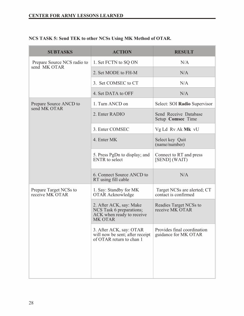
NCS TASK 5: Send TEK to other NCSs Using MK Method of OTAR.
SUBTASKS ACTION RESULT
Prepare Source NCS radio to send MK OTAR
1. Set FCTN to SQ ON N/A
2. Set MODE to FH-M N/A
3. Set COMSEC to CT N/A
4. Set DATA to OFF N/A
Prepare Source ANCD tosend MK OTAR
1. Turn ANCD on Select: SOI Radio Supervisor
2. Enter RADIO Send Receive DatabaseSetup Comsec Time
3. Enter COMSEC Vg Ld Rv Ak Mk vU
4. Enter MK Select key Quit(name/number)
5. Press PgDn to display; andENTR to select
Connect to RT and press[SEND] (WAIT)
6. Connect Source ANCD toRT using fill cable
N/A
Prepare Target NCSs toreceive MK OTAR
1. Say: Standby for MKOTAR Acknowledge
Target NCSs are alerted; CTcontact is confirmed
2. After ACK, say: MakeNCS Task 6 preparations;ACK when ready to receiveMK OTAR
Readies Target NCSs to receive MK OTAR
3. After ACK, say: OTARwill now be sent; after receipt of OTAR return to chan 1
Provides final coordinationguidance for MK OTAR
28
CENTER FOR ARMY LESSONS LEARNED
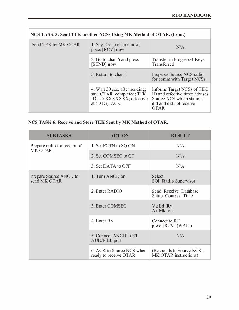
NCS TASK 5: Send TEK to other NCSs Using MK Method of OTAR. (Cont.)
Send TEK by MK OTAR 1. Say: Go to chan 6 now;press [RCV] now
N/A
2. Go to chan 6 and press[SEND] now
Transfer in Progress/1 KeysTransferred
3. Return to chan 1 Prepares Source NCS radiofor comm with Target NCSs
4. Wait 30 sec. after sending; say: OTAR completed; TEKID is XXXXXXXX; effective at (DTG), ACK
Informs Target NCSs of TEK ID and effective time; advises Source NCS which stationsdid and did not receiveOTAR
NCS TASK 6: Receive and Store TEK Sent by MK Method of OTAR.
SUBTASKS ACTION RESULT
Prepare radio for receipt ofMK OTAR
1. Set FCTN to SQ ON N/A
2. Set COMSEC to CT N/A
3. Set DATA to OFF N/A
Prepare Source ANCD tosend MK OTAR
1. Turn ANCD on Select:SOI Radio Supervisor
2. Enter RADIO Send Receive DatabaseSetup Comsec Time
3. Enter COMSEC Vg Ld RvAk Mk vU
4. Enter RV Connect to RTpress [RCV] (WAIT)
5. Connect ANCD to RTAUD/FILL port
N/A
6. ACK to Source NCS whenready to receive OTAR
(Responds to Source NCS’sMK OTAR instructions)
29
RTO HANDBOOK
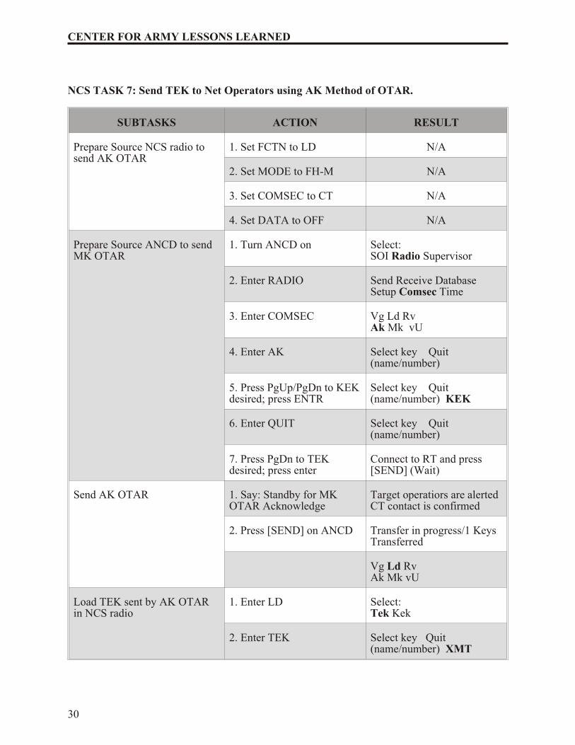
NCS TASK 7: Send TEK to Net Operators using AK Method of OTAR.
SUBTASKS ACTION RESULT
Prepare Source NCS radio tosend AK OTAR
1. Set FCTN to LD N/A
2. Set MODE to FH-M N/A
3. Set COMSEC to CT N/A
4. Set DATA to OFF N/A
Prepare Source ANCD to sendMK OTAR
1. Turn ANCD on Select:SOI Radio Supervisor
2. Enter RADIO Send Receive Database Setup Comsec Time
3. Enter COMSEC Vg Ld Rv Ak Mk vU
4. Enter AK Select key Quit(name/number)
5. Press PgUp/PgDn to KEK desired; press ENTR
Select key Quit(name/number) KEK
6. Enter QUIT Select key Quit(name/number)
7. Press PgDn to TEKdesired; press enter
Connect to RT and press[SEND] (Wait)
Send AK OTAR 1. Say: Standby for MKOTAR Acknowledge
Target operatiors are alertedCT contact is confirmed
2. Press [SEND] on ANCD Transfer in progress/1 KeysTransferred
Vg Ld RvAk Mk vU
Load TEK sent by AK OTARin NCS radio
1. Enter LD Select:Tek Kek
2. Enter TEK Select key Quit(name/number) XMT
30
CENTER FOR ARMY LESSONS LEARNED
NCS TASK 7: Send TEK to Net Operators using AK Method of OTAR. (Cont.)
3. Press PgDn to display and ENTR to select
Connect ANCD to RT
4. Enter Quit Press [LOAD] on RT
5. Connect ANCD to RTAUD/FILL; press [ ]
6. Press [LOAD]/[STO]/and[X]
1 Keys Transferred
Vg Ld RvAk Mk vU
31
RTO HANDBOOK
CHAPTER 5
PRECISION LIGHTWEIGHT GLOBAL POSITIONING SYSTEM RECEIVER(PLGR) TASKS
The ability for soldiers to accurately determine their location has always been a major problem.The Global Positioning System (GPS) has revolutionized land navigation. Ideally, soldiersshould be able to determine their position accurately to within 10 meters. But before such astandard can be achieved, soldiers, and particularly RTOs, must be proficient in the use of GPS.
1. DEFINITION: The GPS is a satellite-based, radio navigational system. It consists of aconstellation with 24 active satellites that interface with a ground-, air-, or sea-based receiver.Each satellite transmits data that enables the GPS receiver to provide precise position and time to the user. The GPS receivers come in several configurations, hand-held, vehicular-mounted,aircraft-mounted, and water craft-mounted.
2. OPERATION: The GPS is based on satellite ranging. It calculates the user’s position onearth by measuring the distance from a group of satellites in space to the user’s location. Foraccurate three-dimensional data, the receiver must track four or more satellites. Most GPSreceivers provide the user with the number of satellites that it is tracking, and whether or not thesignals are good. Some receivers can be manually switched to track only three satellites if theuser knows his altitude. This method provides the user with accurate data much faster than thatprovided by tracking four or more satellites. Each type receiver has a number of mode keys thathave a variety of functions. To better understand how the GPS receiver operates, refer to theoperators’ manual (TB 11-5825-291-10-2, Soldier’s Guide for the PLGR (PrecisionLightweight GPS Receiver)
3. CAPABILITIES: The GPS provides worldwide, 24-hour, all weather, day or night coveragewhen the satellite constellation is complete. The GPS can locate the position of the useraccurately to within 21 meters—95 percent of the time. However, the GPS has been known toaccurately locate the position of the user within 8 to 10 meters. It can determine the distance anddirection from the user to a programmed location or the distance between two programmedlocations called waypoints. It provides exact date and time for the time zone in which the user islocated. The data supplied by the GPS is helpful for missions that require soldiers to know theirexact location including:
• Sighting
• Surveying
• Tactical reconnaissance
• Sensor emplacement.
• Artillery forward observing
• Close air support
33
RTO HANDBOOK
• General navigation
• Mechanized maneuvers
• Engineer surveying
• Amphibious operations
• Parachute operations
• Signal intelligence
• Electronic warfare
• Ground-based forward air control
This data is displayed on the AN/PSN-11 and is also available from a serial data port.
4. LIMITATIONS: A constellation of 24 satellites broadcasts precise signals for use bynavigational sets. The satellites are arranged in six rings that orbit the earth twice each day. TheGPS navigational signals are similar to light rays, so anything that blocks the light will reduce or block the effectiveness of the signals. The more unobstructed the view of the sky, the better thesystem performs.
5. COMPATIBILITY: All GPS receivers have primarily the same function, but the input andcontrol keys vary between the different receivers. The GPS can reference and format positioncoordinates in any of the following systems:
• Degrees, minutes, seconds (DMS): Latitude/longitude-based system with positionexpressed in degrees, minutes, and seconds.
• Degrees, minutes (DM): Latitude/longitude-based system with position expressed indegrees and minutes.
• Universal traverse mercator (UTM): Grid zone system with the northing and eastingposition expressed in meters.
• Military grid reference system (MGRS): Grid zone/grid square system withcoordinates of position expressed in meters.
The following is a list of land navigation subjects from other sections in which the GPS can beused to assist soldiers in navigating and map reading:
• Grid coordinates. GPS makes determining a 4-, 6-, 8-, and 10-digit grid coordinate of a location easy. On most GPS receivers, the position mode will give the user a 10-digitgrid coordinate to their present location.
• Distance and direction. The mode for determining distance and direction depends onthe GPS receiver being used. One thing the different types of receivers have incommon is that to determine direction and distance, the user must enter at leastone-way point (WPT). When the receiver measures direction and distance from the
34
CENTER FOR ARMY LESSONS LEARNED
present location or from waypoint to waypoint, the distance is measured in straight line only. Distance can be measured in miles, yards, feet, kilometers, meters, or nauticalknots or feet. For determining direction, the user can select degrees, mils, or rads.Depending on the receiver, the user can select true north, magnetic north, or grid north.
• Navigational equipment and methods. Unlike the compass, the GPS receiver when seton navigation mode (NAV) will guide the user to a selected way point by actuallytelling the user how far left or right the user has drifted from the desired azimuth. With this option, the user can take the most expeditious route possible, moving around anobstacle or area without replotting and reorienting.
• Mounted land navigation. While in the NAV mode, the user can navigate to a waypoint using steering and distance, and the receiver will tell the user how far he has yetto travel, and at the current speed, how long it will take to get to the way point.
• Navigation in different types of terrain. The GPS is capable of being used in anyterrain; especially more open terrain like the desert.
• Unit sustainment. The GPS can be used to read coordinates to quickly and accuratelyestablish and verify land navigation courses.
6. CONCEPT OF OPERATION: The precision lightweight global positioning system receiver (PLGR) is a highly accurate satellite signal navigation set (referred to as AN/PSN-11).
The AN/PSN-11 is designed for battlefield use anywhere in the world. It is sealed watertight forall weather day or night operation. The AN/PSN-11 is held in the left hand and operated with the thumb of the left hand. Capability is included for installation in ground facilities and air, sea, and land vehicles. The AN/PSN-11 is operated stand-alone using prime battery power and integralantenna. It can be used with an external power source and external antenna.
The AN/PSN-11 provides the user with position coordinates, time, and navigation information ifno obstructions block the line-of-sight satellite signal from reaching the antenna. Valid cryptokeys are used to protect the AN/PSN-11 from intentionally degraded satellite signals.
Many data fields, such as elevation, display units of information. The format of the units can bechanged to the most familiar format.
Map coordinates are entered as a waypoint. When a waypoint is selected as a destination, theAN/PSN-11 provides steering indications, azimuth, and range information to the destination. Adesired course to a waypoint is entered. Offset distance from this course line is shown.
Up to 999 waypoints can be entered, stored, and selected as a destination. A route is defined fornavigation either start-to-end or end-to-start. The route consists of up to nine legs (10 waypoints) linked together.
7. CHARACTERISTICS: The AN/PSN-11 is less than 9.5 inches long, 4.1 inches wide, and2.6 inches deep. It weighs 2.75 pounds with all batteries in place. The small size and light weight make the set easy to carry and use. The durable plastic case is sealed for all-weather use. The
35
RTO HANDBOOK
36
CENTER FOR ARMY LESSONS LEARNED
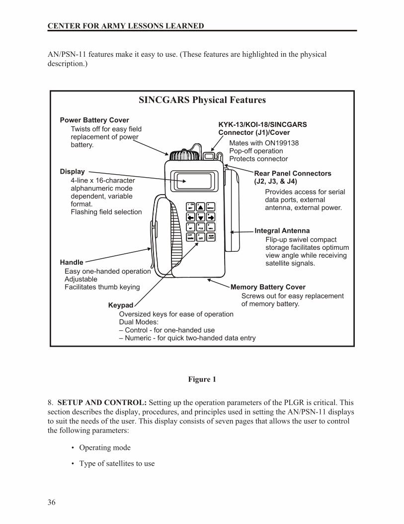
AN/PSN-11 features make it easy to use. (These features are highlighted in the physicaldescription.)
Figure 1
8. SETUP AND CONTROL: Setting up the operation parameters of the PLGR is critical. Thissection describes the display, procedures, and principles used in setting the AN/PSN-11 displaysto suit the needs of the user. This display consists of seven pages that allows the user to controlthe following parameters:
• Operating mode
• Type of satellites to use
KYK-13/KOI-18/SINCGARSConnector (J1)/Cover
SINCGARS Physical Features
Mates with ON199138Pop-off operationProtects connector
Rear Panel Connectors(J2, J3, & J4)
Provides access for serialdata ports, externalantenna, external power.
Integral Antenna
Flip-up swivel compactstorage facilitates optimumview angle while receivingsatellite signals.
Power Battery Cover
Twists off for easy fieldreplacement of powerbattery.
Display
4-line x 16-characteralphanumeric modedependent, variableformat.Flashing field selection
Handle
Easy one-handed operationAdjustableFacilitates thumb keying Memory Battery Cover
Screws out for easy replacementof memory battery.Keypad
Oversized keys for ease of operationDual Modes:– Control - for one-handed use– Numeric - for quick two-handed data entry
• Coordinate system
• Units
• Magnetic variation
• Display customization
• Navigation display mode
• Elevation hold mode
• Time and error formats
• Datum
• Automatic off timer
• Datum port configuration
• AutoMark mode
To set the PLGR up for continuous operation:
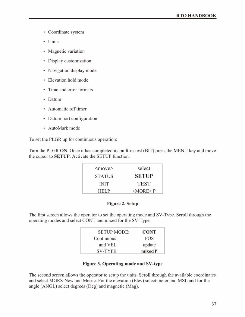
Turn the PLGR ON. Once it has completed its built-in-test (BIT) press the MENU key and move the cursor to SETUP. Activate the SETUP function.
<move> select
STATUS SETUP
INIT TEST
HELP <MORE> P
Figure 2. Setup
The first screen allows the operator to set the operating mode and SV-Type. Scroll through theoperating modes and select CONT and mixed for the SV-Type.
SETUP MODE: CONT
Continuous POS
and VEL update
SV-TYPE: mixed P
Figure 3. Operating mode and SV-type
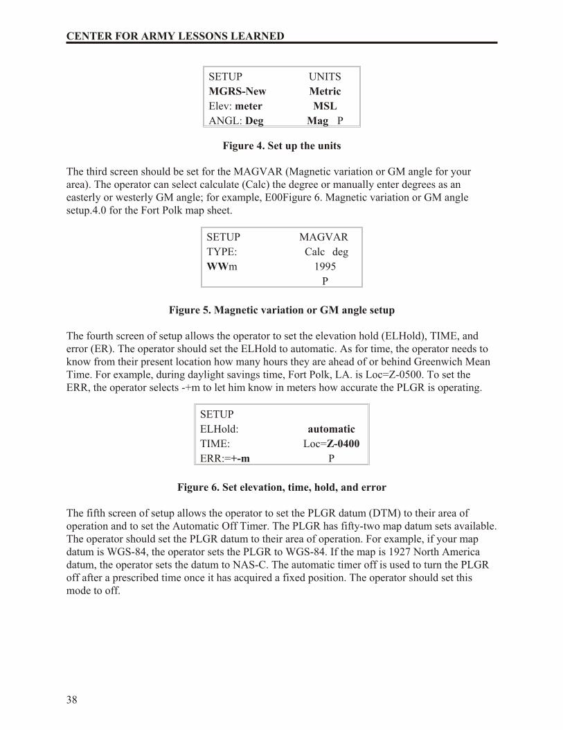
The second screen allows the operator to setup the units. Scroll through the available coordinates and select MGRS-New and Metric. For the elevation (Elev) select meter and MSL and for theangle (ANGL) select degrees (Deg) and magnetic (Mag).
37
RTO HANDBOOK
SETUP UNITS
MGRS-New Metric
Elev: meter MSL
ANGL: Deg Mag P
Figure 4. Set up the units
The third screen should be set for the MAGVAR (Magnetic variation or GM angle for yourarea). The operator can select calculate (Calc) the degree or manually enter degrees as aneasterly or westerly GM angle; for example, E00Figure 6. Magnetic variation or GM anglesetup.4.0 for the Fort Polk map sheet.
SETUP MAGVAR
TYPE: Calc deg
WWm 1995
P
Figure 5. Magnetic variation or GM angle setup
The fourth screen of setup allows the operator to set the elevation hold (ELHold), TIME, anderror (ER). The operator should set the ELHold to automatic. As for time, the operator needs toknow from their present location how many hours they are ahead of or behind Greenwich MeanTime. For example, during daylight savings time, Fort Polk, LA. is Loc=Z-0500. To set theERR, the operator selects -+m to let him know in meters how accurate the PLGR is operating.
SETUP
ELHold: automatic
TIME: Loc=Z-0400
ERR:=+-m P
Figure 6. Set elevation, time, hold, and error
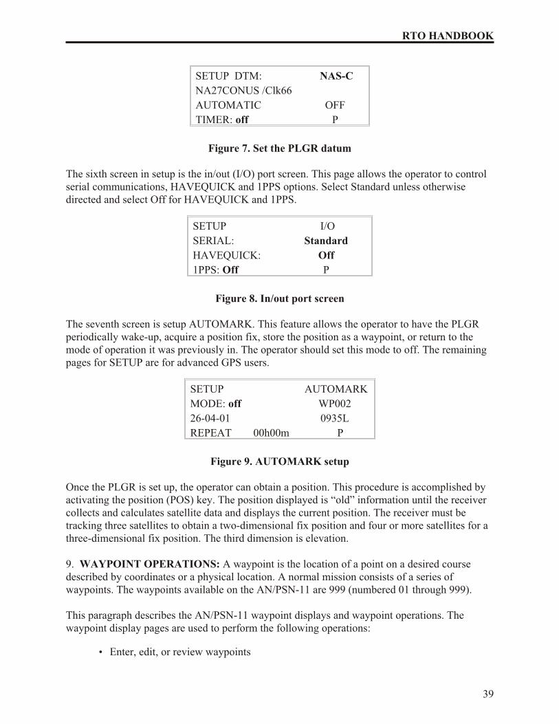
The fifth screen of setup allows the operator to set the PLGR datum (DTM) to their area ofoperation and to set the Automatic Off Timer. The PLGR has fifty-two map datum sets available. The operator should set the PLGR datum to their area of operation. For example, if your mapdatum is WGS-84, the operator sets the PLGR to WGS-84. If the map is 1927 North Americadatum, the operator sets the datum to NAS-C. The automatic timer off is used to turn the PLGRoff after a prescribed time once it has acquired a fixed position. The operator should set thismode to off.
38
CENTER FOR ARMY LESSONS LEARNED
SETUP DTM: NAS-C
NA27CONUS /Clk66
AUTOMATIC OFF
TIMER: off P
Figure 7. Set the PLGR datum
The sixth screen in setup is the in/out (I/O) port screen. This page allows the operator to controlserial communications, HAVEQUICK and 1PPS options. Select Standard unless otherwisedirected and select Off for HAVEQUICK and 1PPS.
SETUP I/O
SERIAL: Standard
HAVEQUICK: Off
1PPS: Off P
Figure 8. In/out port screen
The seventh screen is setup AUTOMARK. This feature allows the operator to have the PLGRperiodically wake-up, acquire a position fix, store the position as a waypoint, or return to themode of operation it was previously in. The operator should set this mode to off. The remainingpages for SETUP are for advanced GPS users.
SETUP AUTOMARK
MODE: off WP002
26-04-01 0935L
REPEAT 00h00m P
Figure 9. AUTOMARK setup
Once the PLGR is set up, the operator can obtain a position. This procedure is accomplished byactivating the position (POS) key. The position displayed is “old” information until the receivercollects and calculates satellite data and displays the current position. The receiver must betracking three satellites to obtain a two-dimensional fix position and four or more satellites for athree-dimensional fix position. The third dimension is elevation.
9. WAYPOINT OPERATIONS: A waypoint is the location of a point on a desired coursedescribed by coordinates or a physical location. A normal mission consists of a series ofwaypoints. The waypoints available on the AN/PSN-11 are 999 (numbered 01 through 999).
This paragraph describes the AN/PSN-11 waypoint displays and waypoint operations. Thewaypoint display pages are used to perform the following operations:
• Enter, edit, or review waypoints
39
RTO HANDBOOK
• Copy waypoints
• Determine the distance between waypoints
• Calculate a new waypoint
• Clear waypoints
• Define a mission route
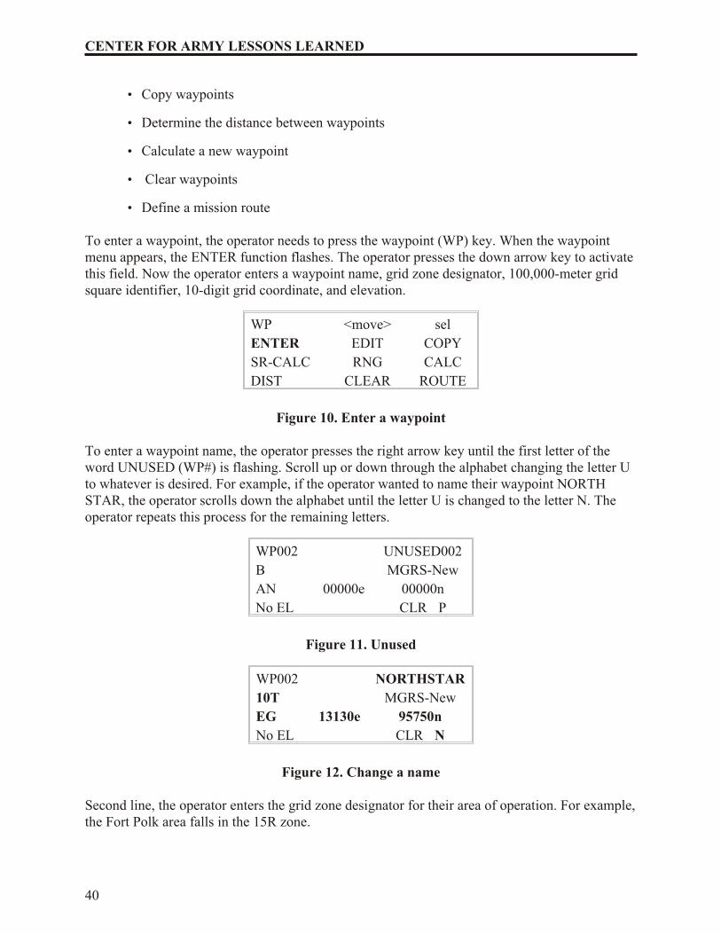
To enter a waypoint, the operator needs to press the waypoint (WP) key. When the waypointmenu appears, the ENTER function flashes. The operator presses the down arrow key to activatethis field. Now the operator enters a waypoint name, grid zone designator, 100,000-meter gridsquare identifier, 10-digit grid coordinate, and elevation.
WP <move> sel
ENTER EDIT COPY
SR-CALC RNG CALC
DIST CLEAR ROUTE
Figure 10. Enter a waypoint
To enter a waypoint name, the operator presses the right arrow key until the first letter of theword UNUSED (WP#) is flashing. Scroll up or down through the alphabet changing the letter Uto whatever is desired. For example, if the operator wanted to name their waypoint NORTHSTAR, the operator scrolls down the alphabet until the letter U is changed to the letter N. Theoperator repeats this process for the remaining letters.
WP002 UNUSED002
B MGRS-New
AN 00000e 00000n
No EL CLR P
Figure 11. Unused
WP002 NORTHSTAR
10T MGRS-New
EG 13130e 95750n
No EL CLR N
Figure 12. Change a name
Second line, the operator enters the grid zone designator for their area of operation. For example, the Fort Polk area falls in the 15R zone.
40
CENTER FOR ARMY LESSONS LEARNED
Third line, the operator must enter a 10-digit grid coordinate with its 100,000-meter grid squareidentifier. For example, if the waypoint location is Carnis Village, Fort Polk map sheet, the100,000-meter grid square identifier is WQ. Then, the operator plots the grid coordinates on themap and enters it into the PLGR.
Note: Operator plots 8-digit grid coordinates, however a 10-digit coordinate is entered.Therefore, the 5th and 10th digit entered is a zero (0).
For the fourth line, if the elevation of the waypoint is known, the operator can enter it. If theelevation is not known the operator can just leave the data as zero or No EL. The operator moves the cursor until the Up and Down arrow symbol appears before the letter P or N in bottom rightcorner. When activating the down arrow key the operator stores the waypoint into the PLGR’smemory. The PLGR notifies the operator that the waypoint has been stored.
Note: When entering numbers, the number lock (NUM LOCK) can be activated. The letter Nappears in the bottom right corner allowing the operator to use the numbers on the keypad ratherthen scrolling up/down.
10. NAVIGATION: Navigation (NAV) is using the AN/PSN-11 to find your present position,relative to other points. The AN/PSN-11 provides azimuth, range, and steering information in avariety of formats. There are four navigation display modes that may be accessed and selected.The navigation display mode selected determines the type of information shown on thenavigation displays. These navigation displays give the user the most useful information for acertain mission profile: SLOW, 2D FAST, 3D FAST, or CUSTOM.
In SLOW NAV mode, the AN/PSN-11 performs two-dimensional (2D) NAV. Slow NAV modeis used for land or sea, when the user cannot maintain the minimum speed necessary (about 1.5kmph).
In 2D FAST NAV mode, the AN/PSN-11 performs two-dimensional (2D) NAV. 2D fast NAVmode is used for land or sea, when the user can maintain the minimum speed necessary for GPSto compute navigation parameters based on velocity.
In 3D FAST NAV mode, the AN/PSN-11 performs three-dimensional (3D) NAV. 3D fast NAVmode has an APPROACH sub-mode. 3D fast NAV mode is used for air, when the user cantravel in three dimensions and can maintain the minimum speed necessary for GPS to computenavigation parameters based on velocity.
In CUSTOM NAV mode, the AN/PSN-11 displays users’ navigational pages as desired. It canbe set up to support the individual user’s performance or mission requirements. The followingcustom display modes are available:
• Direct
• Course to
41
RTO HANDBOOK
• Course from
• Route
• Approach
To navigate with the PLGR on land in a dead-reckoning method, the PLGR NAV mode isaccomplished as follows:
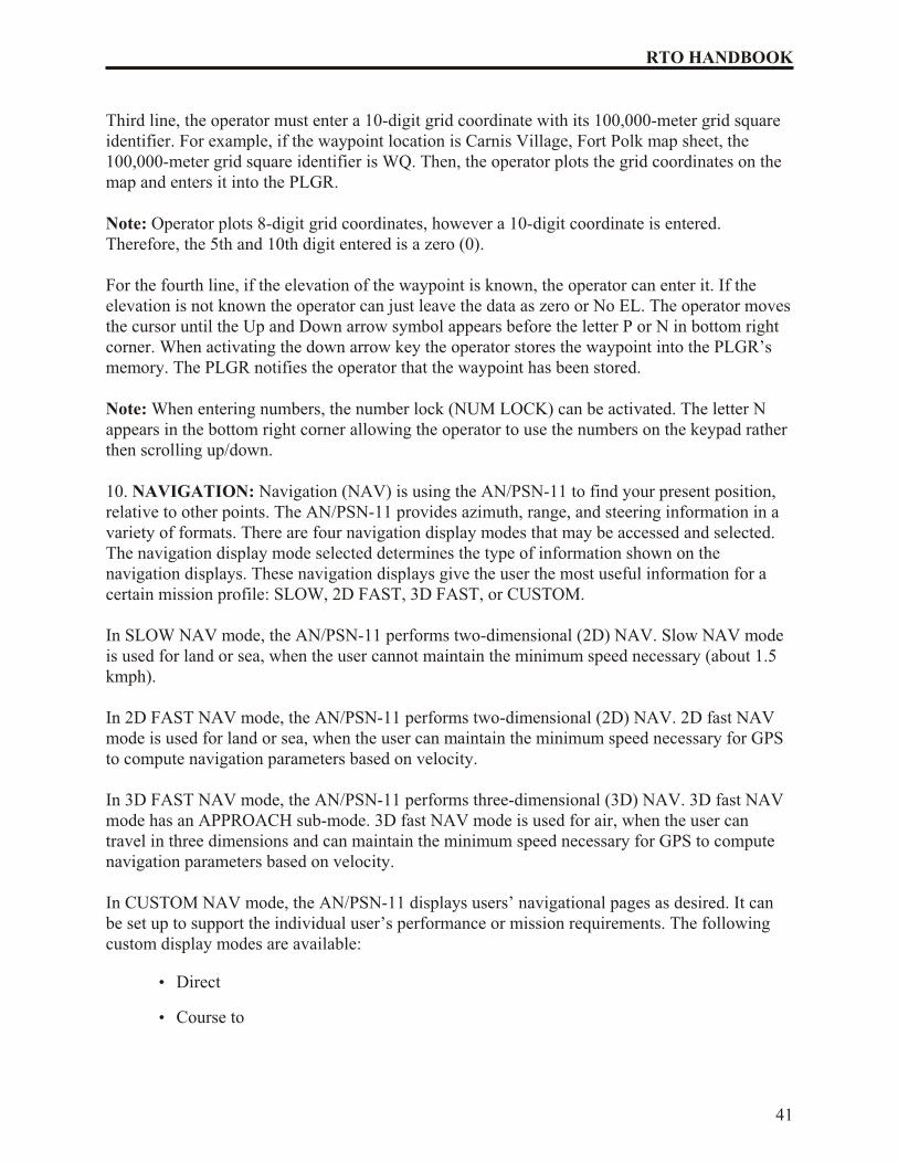
The operator presses the NAV key activating the NAV function. The first screen that appears isthe NAV mode. For example, SLOW, 2D FAST, 3D FAST, CUSTOM, DIRECT, CRS (course)TO, and CRS (course) FROM.
2D FAST DIRECT
WP002 NORTHSTAR002
P
Figure 13. Navigation mode
The operator selects the 2D FAST and DIRECT. The second line is the waypoint to benavigated. (To choose the desired waypoint, scroll through the waypoints that are stored.)
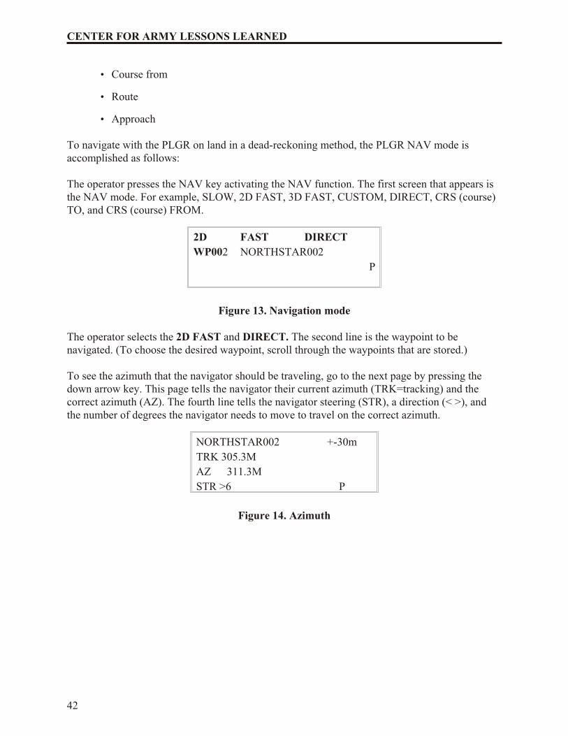
To see the azimuth that the navigator should be traveling, go to the next page by pressing thedown arrow key. This page tells the navigator their current azimuth (TRK=tracking) and thecorrect azimuth (AZ). The fourth line tells the navigator steering (STR), a direction (< >), andthe number of degrees the navigator needs to move to travel on the correct azimuth.
NORTHSTAR002 +-30m
TRK 305.3M
AZ 311.3M
STR >6 P
Figure 14. Azimuth
42
CENTER FOR ARMY LESSONS LEARNED
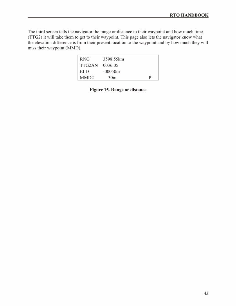
The third screen tells the navigator the range or distance to their waypoint and how much time(TTG2) it will take them to get to their waypoint. This page also lets the navigator know whatthe elevation difference is from their present location to the waypoint and by how much they will miss their waypoint (MMD).
RNG 3598.55km
TTG2AN 0036:05
ELD -00050m
MMD2 30m P
Figure 15. Range or distance
43
RTO HANDBOOK
CHAPTER 6
AUTOMATED NET CONTROL DEVICE (ANCD) TASKS
The ANCD system replaced the paper version SOI, the KYK 13, and MX 18290 Hopset Device.
The ANCD was designed with the capability of loading the SINCGARS radio with COMSECand frequency hopping data without the use of the KYK 13 and the MX 18290 (Hopset Device).The ANCD also provides the operators with frequencies, call signs, suffixes, expanders, andother SOI information, except Authentication Table. This chapter provides the knowledge RTOsneed to transfer COMSEC/FH data and SOI information from ANCD to ANCD, extract SOIinformation from an ANCD, and load SINCGARS radio using Mode 2 fill. The chapter alsodescribes how to store data sent by over the air rekeying (OTAR) and Broadcast mode
Characteristics of the ANCD
1. Size: 6.3" x 4.4" x 2.0"
2. Weight: Approximately 2 pounds with batteries
3. Power Source: 3 3 volt lithium batteries
4. Purpose: Used to transfer and store COMSEC keys, frequency hop (FH) data anddisplay, transfer and store SOI information.
5. The ANCD eliminates the use of the KYK 13, KYX 15, KOI 18, MX 18290, and thepaper SOI.
Main Menu
1. The main menu consists of 3 areas:
a. SOI pertains to SOI Information.
b. Radio pertains to COMSEC keys/FH data to be loaded into the radio.
c. Supervisor pertains to areas performed by the supervisor “only.”
2. Selection of main menu areas:
a. Use the ARROW key function by pressing either the left or right arrow keysthen press the ENTER key.
b. Press the corresponding capital letter on the keyboard to take you directly to aspecific topic. For example:
S - for signal operating instructions
R - for radio
U - for supervisor
45
RTO HANDBOOK
Transfer COMSEC keys/FH data (controlled PE)
1. To transfer COMSEC keys/FH data, one ANCD must be selected as the SOURCEANCD and the other as the TARGET ANCD.
2. Turn on ANCD.
3. Enter RADIO.
4. Sub menu will display:
a. SEND used to send COMSEC keys/FH data to a radio, ANCD, STU (securetelephone unit), and PC (personal computer).
b. RECEIVE used to receive COMSEC keys/FH data from ANCD, CFD(COMSEC fill device), STU, PC, and MX (ECCM fill device MX 18290)
c. DATABASE used to display, modify, remove, copy, and build COMSECkeys/FH data.
d. SETUP used to set up ANCD to operate either on ICOM or NONICOM.
e. COMSEC used to generate variables (VG), load (LD), receive variables (RV),automatic key (AK), manual key (MK), and variable update (VU).
f. TIME used to set the Julian date and the hours and minutes (24 hour) manuallyinto the radio.
To transfer COMSEC keys/FH data one ANCD must be set up as the SOURCE ANCD.
1. Press the ON/OFF key to turn on the ANCD of the Source ANCD.
2. Select RADIO: Depress the cursor on the keyboard then press ENTER or press “R” for radio.
3. Enter SEND.
4. Select ANCD and press ENTER.
5. Select DATABASE and press ENTER.
6. ANCD will ask: Do you want to include TIME? Y/N? ENTER “Y” for yes.
7. Connect both ANCDs with fill cable (W4) and press SEND on the ANCD keyboard.
Note: The receiving ANCD must press RECEIVE on the ANCD Keyboard within 20seconds.
8. Display screen on the sending ANCD will show preparing to transfer time and thenboth ANCDs will show TRANSFER IN PROGRESS. Once the transfer has beencompleted, the display screen will show TRANSFER SUCCESSFUL.
46
CENTER FOR ARMY LESSONS LEARNED
To receive COMSEC/HF data one ANCD must be set up as the TARGET ANCD.
1. Turn on the ANCD.
2. Select RADIO and press ENTER.
3. Select RECEIVE and press ENTER.
4. Receive From: Select ANCD and press ENTER.
5. Select DATABASE and press ENTER.
6. Do you want to delete FH and COMSEC data? YES must be selected in order toproceed.
7. Connect to ANCD and press receive (RCV).
Notes: DO NOT press RCV until the SOURCE ANCD is ready.
Receive must be pressed within 20 seconds after SOURCE ANCD sends data.
8. The TARGET ANCD display screen will show: TRANSFER IN PROGRESS. Oncetransfer is complete, display screen will show: TRANSFER SUCCESSFUL.
To perform before operations preventive maintenance checks and services (PMCS) onSINCGARS radio and load the radio with required data the following steps must beaccomplished in the exact order:
1. Obtain the required single channel frequencies from the ANCD when you areoperating in the division support command (DISCOM)
NET Time Period 01:
a. MAN
b. CUE
Note: The MAN channel is normally loaded but NOT the CUE channel. Channels 1through 6 are loaded only if required by unit SOP.
2. Set RT controls.
a. FCTN to LD
b. MODE to SC
c. COMSEC to PT/CT
d. CHAN to CUE/MAN/1 6
3. Press FREQ.
47
RTO HANDBOOK
4. Press CLR.
5. Load Frequency obtained from ANCD.
6. Press STO.
7. Repeat steps “C” through “F” for each single channel frequency required to be loaded.
8. Set FCTN to SQ.
Load COMSEC keys and frequency hopping data using Mode 2 fill.
1. Preparation of ANCD for Mode 2 fill.
a. Turn on ANCD and SINCGARS radio.
b. Set SINCGARS radio up to load COMSEC keys and frequency hopping (FH)data:
• COMSEC to CT
• FCTN to LD
• MODE to FH
• CHAN to MAN
• DATA to OFF
c. Select: RADIO on ANCD and press ENTER.
d. Select: SEND and press ENTER.
e. Select: RADIO and press ENTER.
f. Select: ICOM and press ENTER.
g. Connect to RT AUD/Fill connector using the (W4) fill cable..
h. Set FCTN control knob on radio to LD.
i. Display will show: Do you want to include TIME? Y/N? ENTER “N” for no.
Note: Time must be entered manually. The RT is not set up to receive the clockfrom the ANCD, however for an accurate time you can use the GPS (GlobalPositioning System) to load the time into the RT.
j. Press LOAD on radio.
k. Display screen on ANCD will show “TRANSFER IN PROGRESS,” then“ICOM TRANSFER SUCCESSFUL.”
48
CENTER FOR ARMY LESSONS LEARNED
Note: The Mode 2 fill procedure loads the radio with one load set, containingCOMSEC keys and FH data for all six (6) channels. If there is more than one load set stored in the ANCD, the one shown as “Default Identification” (DI) will beloaded into the radio when the Mode 2 fill procedure is used.
Enter secure, frequency hopping net using Hot Start net opening procedures.
1. Julian date calendar
a. Obtained from NCS
b. Located in TM 11 5820 890 10 8 (SINCGARS) Operator’s Manual page A 3(Appendix A)
2. Procedure for loading Julian date into SINCGARS radio
a. Set: FCTN to LD.
b. Press: TIME (display shows “DD”).
c. Press: CLR (display shows “_ _”).
d. Enter: JULIAN DATE.
e. Press: STO (Julian date loaded into RT).
3. Procedure for loading SYNC time into SINCGARS radio
a. Turn on ANCD.
b. Enter: RADIO (display will show HH:MM:SS).
c. Press: TIME (display shows HHMM).
d. Press: CLR (display shows “_ _ _ _”).
e. Enter: HOUR (same as ANCD).
f. Enter: MINUTES (add 1 minute to clock on RT).
g. Press: STO (store time when clock on ANCD shows 60 or 00 seconds).
h. Set Channel Selector Switch to net ID IAW SOI.
4. Requirement to call NCS once data and SYNC time have been loaded into theSINCGARS radio.
“NCS, THIS IS STATION (NR), OVER.”
Following the Hot Start net opening procedure, the SINCGARS radio in now ready tocommunicate in the FH mode. CT net and net opening is completed for the operator.
49
RTO HANDBOOK
Quick and Dirty Loading
1. Install SINCGARS radio:
a. Install battery into battery box and connect to RT.
b. Connect whip antenna-to-antenna base hand tight.
c. Connect antenna base RT ANT hand tight.
d. Connect handset (H-250) to AUDIO DAT1.
2. Prepare RT to be loaded using ANCD:
a. Set FCTN knob to TST. Wait for GOOD on display.
b. Set FCTN knob to LD.
c. Set COMSEC knob to CT.
d. Set MODE knob to FH.
e. Clear audio alarm in handset to solid tone (press handset twice).
3. Prepare ANCD and load RT:
a. Turn on ANCD and enter RADIO at the main menu.
b. At next three screens SEND, RADIO, and ICOM press ENTER.
c. Follow guidance for next two steps by pressing down arrow.
d. Enter Y at the next menu (TIME), then press LOAD on the RT.
4. Load single channel frequency:
a. Set MODE knob to S3.
b. Set CHAN knob to desired position.
c. On the keypad press FREQ+CLR.
d. On the keypad enter the frequency given and press STO.
5. Set RF PWR to desired setting (LO, M, HI).
6. Set FCTN knob to SQ ON and conduct a radio check using proper procedures andprowords.
50
CENTER FOR ARMY LESSONS LEARNED
CHAPTER 7
RTO PACKING LIST AND CHECKLIST
Radio telephone operators (RTOs) are required to understand their respective radio systems aswell as the tactical maneuver plan. RTOs are the commander’s ears and, as such, willcontinuously monitor radio transmissions and report any tactical developments to theircommander ASAP. RTOs should not only carry the radio, but also take an active role inmonitoring and controlling the operation with minimal guidance. As stated earlier, the RTO isthe walking, talking tactical operations center for the small unit leader.
Each RTO should have as a minimum:
• Appropriate radio system with 2 handsets, long-whip, and short whip antennas
• Appropriate COMSEC in the radio
• COMMEX time and place
• Challenge/password and number combination
• Effective change over time
• Task force net IDs/call sign quick reference (CMD, O/I, A/L)
• Retrans plan (If applicable)
• Tactical plan/execution checklist
• Late net entry procedures
• Pen, pencil, and water proof paper or laminated reporting log sheets
• Digital watch (continuously updated with plugger time)
• Pre-made field expedient 292 antenna
• Flashlight
• Poncho
• Extra batteries
• Map
• Extra BNC or barrel connectors (connects antenna to radio)
51
RTO HANDBOOK
CHAPTER 8
PREVENTATIVE MAINTENANCE CHECKS AND SERVICES (PMCS)FOR ADVANCED SYSTEMS IMPROVEMENT PROGRAM (ASIP)
RADIOS
Just as any soldier checks and maintains his weapon, the RTO checks and maintains hisequipment. The welfare of the entire unit rides on the shoulders of the RTO. If the RTO does notmaintain his equipment, he and his unit will not be able to communicate. The unit that cannotcommunicate when necessary, will not survive, much less accomplish its mission.
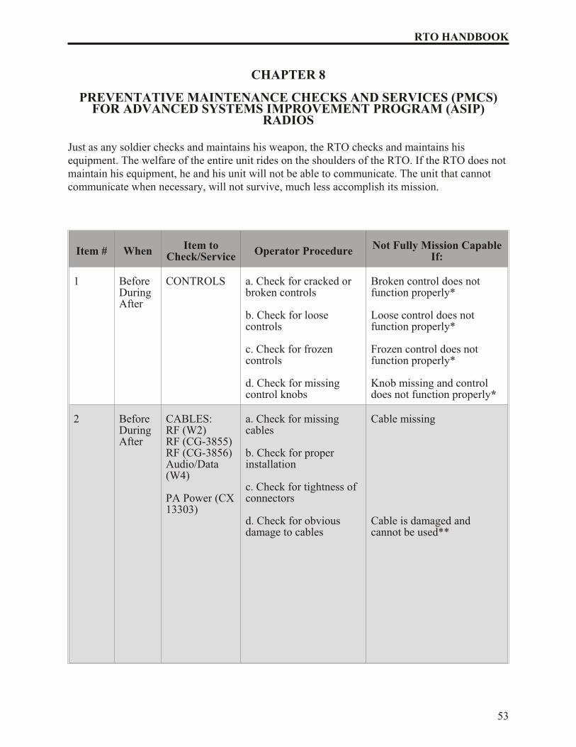
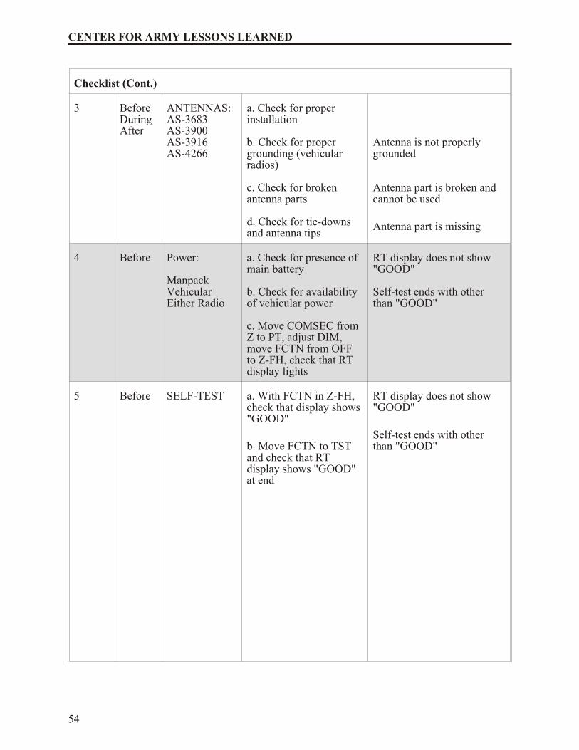
Item # When Item toCheck/Service
Operator Procedure Not Fully Mission CapableIf:
1 BeforeDuringAfter
CONTROLS a. Check for cracked orbroken controls
b. Check for loosecontrols
c. Check for frozencontrols
d. Check for missingcontrol knobs
Broken control does notfunction properly*
Loose control does notfunction properly*
Frozen control does notfunction properly*
Knob missing and controldoes not function properly*
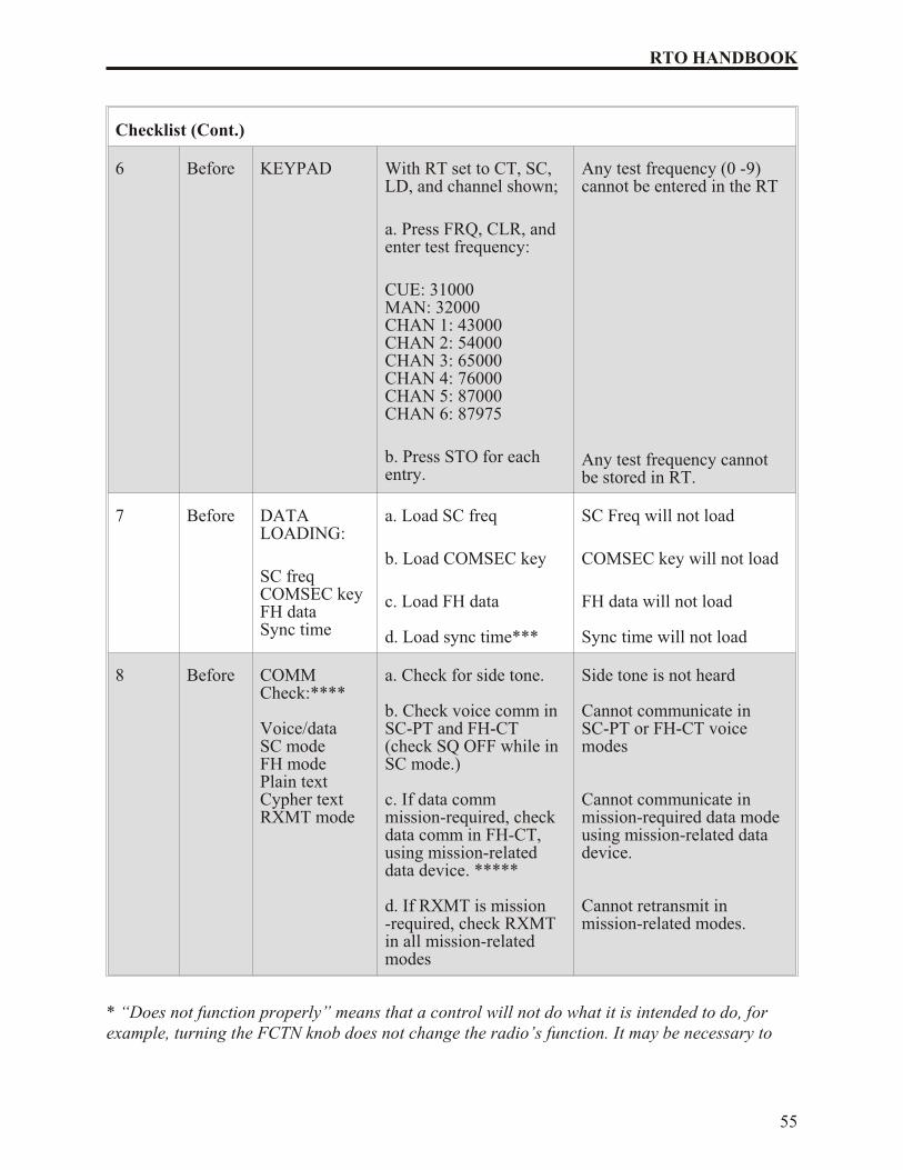
b. Check voice comm inSC-PT and FH-CT(check SQ OFF while inSC mode.)
c. If data commmission-required, checkdata comm in FH-CT,using mission-relateddata device. *****
d. If RXMT is mission-required, check RXMTin all mission-relatedmodes
Side tone is not heard
Cannot communicate inSC-PT or FH-CT voicemodes
Cannot communicate inmission-required data modeusing mission-related datadevice.
Cannot retransmit inmission-related modes.
* “Does not function properly” means that a control will not do what it is intended to do, forexample, turning the FCTN knob does not change the radio’s function. It may be necessary to
55
RTO HANDBOOK
wait until Item 8 (Communications Check) to determine for sure that some controls do or do notfunction properly.
** "Damaged and cannot be used” means that after visual inspection or operational check, youdetermine that a piece of equipment is faulty and, therefore, will not support your missionrequirements or presents a safety hazard.
*** Use of the ICOM fill procedure is appropriate here, but separate checks of COMSEC keys,FH data, and sync time elements are required.
**** Operators with special requirements (NCS for example) should check those functions thatare important to mission operations (ERF for example). Skip this step if tactical situationprohibits transmitting.
***** Unless your mission is likely to require use of data mode or retransmission operations,you do not need to perform these two checks.
56
CENTER FOR ARMY LESSONS LEARNED
CHAPTER 9
TROUBLESHOOTING GUIDE
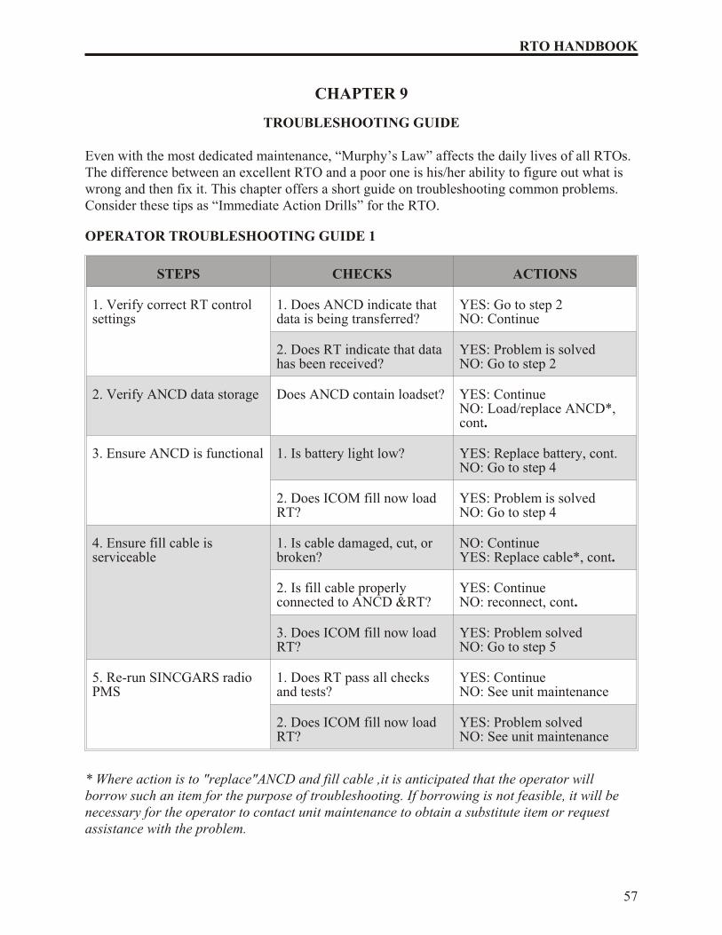
Even with the most dedicated maintenance, “Murphy’s Law” affects the daily lives of all RTOs.The difference between an excellent RTO and a poor one is his/her ability to figure out what iswrong and then fix it. This chapter offers a short guide on troubleshooting common problems.Consider these tips as “Immediate Action Drills” for the RTO.
OPERATOR TROUBLESHOOTING GUIDE 1
STEPS CHECKS ACTIONS
1. Verify correct RT controlsettings
1. Does ANCD indicate thatdata is being transferred?
YES: Go to step 2NO: Continue
2. Does RT indicate that datahas been received?
YES: Problem is solvedNO: Go to step 2
2. Verify ANCD data storage Does ANCD contain loadset? YES: ContinueNO: Load/replace ANCD*,cont.
3. Ensure ANCD is functional 1. Is battery light low? YES: Replace battery, cont.NO: Go to step 4
2. Does ICOM fill now loadRT?
YES: Problem is solvedNO: Go to step 4
4. Ensure fill cable isserviceable
1. Is cable damaged, cut, orbroken?
NO: ContinueYES: Replace cable*, cont.
2. Is fill cable properlyconnected to ANCD &RT?
YES: ContinueNO: reconnect, cont.
3. Does ICOM fill now loadRT?
YES: Problem solvedNO: Go to step 5
5. Re-run SINCGARS radioPMS
1. Does RT pass all checksand tests?
YES: ContinueNO: See unit maintenance
2. Does ICOM fill now loadRT?
YES: Problem solvedNO: See unit maintenance
* Where action is to "replace"ANCD and fill cable ,it is anticipated that the operator willborrow such an item for the purpose of troubleshooting. If borrowing is not feasible, it will benecessary for the operator to contact unit maintenance to obtain a substitute item or requestassistance with the problem.
57
RTO HANDBOOK
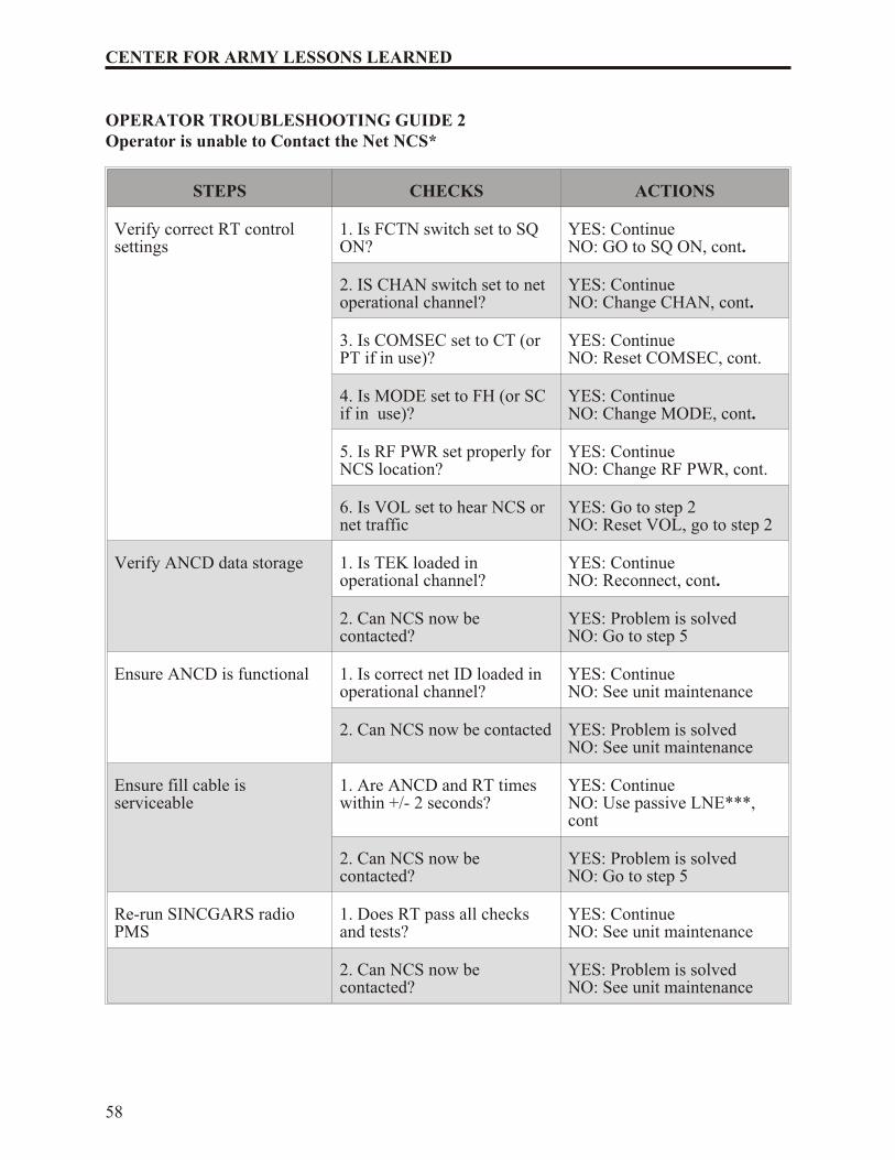
OPERATOR TROUBLESHOOTING GUIDE 2Operator is unable to Contact the Net NCS*
STEPS CHECKS ACTIONS
Verify correct RT controlsettings
1. Is FCTN switch set to SQON?
YES: ContinueNO: GO to SQ ON, cont.
2. IS CHAN switch set to netoperational channel?
YES: ContinueNO: Change CHAN, cont.
3. Is COMSEC set to CT (orPT if in use)?
YES: ContinueNO: Reset COMSEC, cont.
4. Is MODE set to FH (or SCif in use)?
YES: ContinueNO: Change MODE, cont.
5. Is RF PWR set properly for NCS location?
YES: ContinueNO: Change RF PWR, cont.
6. Is VOL set to hear NCS ornet traffic
YES: Go to step 2NO: Reset VOL, go to step 2
Verify ANCD data storage 1. Is TEK loaded inoperational channel?
YES: ContinueNO: Reconnect, cont.
2. Can NCS now becontacted?
YES: Problem is solvedNO: Go to step 5
Ensure ANCD is functional 1. Is correct net ID loaded inoperational channel?
YES: ContinueNO: See unit maintenance
2. Can NCS now be contacted YES: Problem is solvedNO: See unit maintenance
Ensure fill cable isserviceable
1. Are ANCD and RT timeswithin +/- 2 seconds?
YES: ContinueNO: Use passive LNE***,cont
2. Can NCS now becontacted?
YES: Problem is solvedNO: Go to step 5
Re-run SINCGARS radioPMS
1. Does RT pass all checksand tests?
YES: ContinueNO: See unit maintenance
2. Can NCS now becontacted?
YES: Problem is solvedNO: See unit maintenance
58
CENTER FOR ARMY LESSONS LEARNED
* If other traffic can be heard on the net, problem is assumed to rest with the NCS station.
** ANCD time may not be valid if it has been more that 24 hours since ICOM fill of radio
*** Passive late net entry (LNE)
OPERATOR TROUBLESHOOTING GUIDE 3
STEPS CHECKS ACTIONS
Perform passive late net entry (LNE)
1. Does RT display show:"LF XXX"?
YES: Wait for traffic on net,contNO: Adjust dim switch, cont.
2. Is traffic heard and "L"dropped from display?
YES: Problem is solvedNO: Go to step 2
Check VOL control setting 1. Is VOL set high enough tohear traffic?
YES: Go to step 3NO: Adjust VOL, cont.
2. Is traffic now heard? YES: Problem is solvedNO: Go to step 3
Ensure that handset isworking
1. Is handset operational? YES: Go to step 4NO: Replace item, cont.
2. Is traffic now heard? YES: Problem is solvedNO: Go to step 4
Verify sync time* 1. Are ANCD and RT timeswithin +/- 2 seconds?
YES: Go to step 5NO: Reload sync time, cont.
2. Is traffic now heard? YES: Problem is solvedNO: Go to step 5
59
RTO HANDBOOK
Verify FH data 1. Is there FH data loaded inthe operational channel?
YES: ContinueNO: Reload RT, cont.
2. Is traffic now heard? YES: Problem is solvedNO: Continue
3. Is correct net ID loaded inoperational channel
YES: Go to step 6NO: Change net ID, cont.
4. Is traffic now heard? YES: Problem is solvedNO: Go to step 6
OPERATOR TROUBLESHOOTING GUIDE 3 (Cont.)
Manpack only** - checkmain battery
1. Does main battery need tobe changed?
YES: Replace battery, cont.NO: Go to step 7
2. Is traffic now heard? YES: Problem is solvedNO: Go to step 7
Perform Hot Start net entry 1. Do COMSEC/FH data load in RT?
YES: ContinueNO: Go to TS Guide 1
2. Is traffic now heard? YES: Problem is solvedNO: Continue ****
3. Can NCS be contacted? YES: Problem is solvedNO: See unit maintenance
* ANCD time may not be valid if it has been more than 24 hours since ICOM fill of radio.|
** For vehicular radios, skip this step and continue with Step 7. Placing RF PWR in HI andpressing PTT can check battery power. Signal display of 2 or less indicates your battery is weak.
*** Operator has option of using CUE and ERF method of late net entry in lieu of the Hot Startprocedure if desired.
**** The possibility that there is no traffic on the net must be considered. Try to contact yourNCS to check serviceability of your radio
.
60
CENTER FOR ARMY LESSONS LEARNED
CHAPTER 10
FIELD EXPEDIENT ANTENNAS
Communications are affected by a host of variables. Range sought, weather, terrain, oratmospherics can affect signal strength without warning. Standard whip antennas may not be upto the task, especially when transmitting under difficult conditions. Field expedient antennas candramatically improve both transmission and reception ranges. The effective RTO knows how toset up such an antenna and has the material needed to do so.
Figure 1
Parts List:
A) 65 feet of gutted 550 cord
B) 5 insulators
C) Four 6.5 feet lengths of antenna elements (16 gauge copper wire, see note 2).
D) Three 1 foot long gutted 550 cord (see note 3).
E) 50 feet of coax cable (RG-58 or RH-174
61
RTO HANDBOOK
Field Expedient RC-292
GRA-50 or otherun-insulated wire
A B
B
B
C
D
C
E
F
Insulated copperwire (i.e. WF-16)
Center-CoreConductor
Outer-BraidConductor
Core Insulator
Outer Insulator
Coax CableConnection Blowup
(See note 4)
Construction:
62
CENTER FOR ARMY LESSONS LEARNED
F) Solderless BNC connector (see note 4).
Notes:
1) Insulators should be made of a semi-flexible plastic (i.e., spoons, flashlight lenses, etc.).
2) Use wire from GRA-50 dipole antenna for the radiator element.
3) 550 cord end is tied in a loop to create a slip knot to put ends of sticks through duringexecution.
4) Once coax is connected, use electrical tape to secure and cover bare wires.
Figure 2
Field Expedient Antenna Erection
Tree limb20-30 feet high
4-6 foot sticks
Radio
Ground Plane
Radiator
Canteen or rock tothrow over limb
CHAPTER 11
ADVANCED SYSTEMS IMPROVEMENT PROGRAM (ASIP)
RADIO RANGES AND BATTERY USAGE
As indicated in the previous chapter, there are numerous factors that affect the range of a radio.This chapter examines the effects of two such factors: the radios themselves and their batteries.Power settings and modes affect the ranges offered by most radios. Battery life not only affectsthe length of time a radio will work but also how much power it can generate. Lower powersettings obviously extend battery life. Heavy transmission activity shortens battery life. Anexcellent RTO knows from experience how long he can expect his batteries to last in anyoperation. He also knows which mode offers the best balance between transmission power anddurability.
1. PURPOSE. Provide operators a guide to use as a planning tool for range capabilities of theASIP. Also, provide operators of the ASIP radios and associated equipment general guidelinesregarding the number of hours a particular type battery is expected to remain serviceable.
2. GENERAL.
a. Planning ranges. The planning ranges for the ASIP are based on line-of-sight (LOS)and are average for normal conditions. Ranges depend upon location, sighting, weather,and antenna used. Use of the OE-254 will increase ranges.
b. Battery usage. It is important to understand that the times presented are the result ofcomputations as well as experience. Hours of service will vary depending on how longthe battery was in storage prior to use, temperature when being used, and other factorsthat cannot be clearly defined. Even so, these times offer the RTO a basis for planningbattery requirements.
3. PLANNING RANGES FOR THE ASIP.
TYPE COMM RF PWR RANGE
VOICE LOW (LO) 200 M TO 400 M
VOICE MEDIUM (M) 400 M TO 5 KM
VOICE HIGH (H) 5 KM TO 10 KM
VOICE PWR AMP (PA) 10 KM TO 40 KM
DATA 600-4800 BPS 16000 BPS
3 KM TO 5 KM1 KM TO 3 KM
63
RTO HANDBOOK
4. EXPECTED BATTERY LIFE.
MANPACK RADIO MAIN POWER(BA5590 with RF set to HI)
VOICE/DATA (FH & CT) ASIP
Normal (Operator) 33 hours
Heavy (NCS) TBD
Standby (STBY) 3 months
REMOTE CONTROL UNIT (RCU)(BA5590 with RF set to HI)
VOICE/DATA (FH & CT) ASIP
Normal (Operator) TBD
Heavy (NCS) TBD
Standby (STBY) 3 months
HOLD-UP BATTERY (HUB)(BA5372)
USE ASIP
Back-up 6 months
Continuous or extended use Monthly
64
CENTER FOR ARMY LESSONS LEARNED
ANCD MAIN POWER
TYPE OF USE LOADED WITH 3BA5123s
LOADED WITH 1 9-volt
Normal (primary SOIreference)
30 hrs 10 hrs
Heavy (NCS-frequent datatransfers)
10 hrs 5 hrs
Loaded in OFF position 2+ months 1+ month
PLGR BATTERY
BATTERY TYPE NOMEN Continuous Use
Lithium (main) BA5800 20 hrs
AA-alkaline BA30588 8 hrs
Lithium (memory) LS6 1 year
65
RTO HANDBOOK
APPENDIX A
JULIAN DATE CALENDAR
Julian Date Calendar (Regular Year)
Day/Mo JAN FEB MAR APR MAY JUN JUL AUG SEP OCT NOV DEC
1 01 32 60 91 21 52 82 13 44 74 05 35
2 02 33 62 92 22 53 83 14 45 75 06 36
3 03 34 63 93 23 54 84 15 46 76 07 37
4 04 35 63 94 24 55 85 16 47 77 08 38
5 05 36 64 95 25 56 86 17 48 78 09 39
6 06 37 65 96 26 57 87 18 49 79 10 40
7 07 38 66 97 27 58 88 19 50 80 11 41
8 08 39 67 98 28 59 89 20 51 81 12 42
9 09 40 68 99 29 60 90 21 52 82 13 43
10 10 41 69 00 30 62 91 22 53 83 14 44
11 11 42 70 01 31 63 92 23 54 84 15 45
12 12 43 71 02 32 63 93 24 55 85 16 46
13 13 44 72 03 33 64 94 25 56 86 17 47
14 14 45 73 04 34 65 95 26 57 87 18 48
15 15 46 74 05 35 66 96 27 58 88 19 49
16 16 47 75 06 36 67 97 28 59 89 20 50
17 17 48 76 07 37 68 98 29 60 90 21 51
18 18 49 77 08 38 69 99 30 62 91 22 52
19 19 50 78 09 39 70 00 31 63 92 23 53
20 20 51 79 10 40 71 01 32 63 93 24 54
21 21 52 80 11 41 72 02 33 64 94 25 55
22 22 53 81 12 42 73 03 34 65 95 26 56
23 23 54 82 13 43 74 04 35 66 96 27 57
24 24 55 83 14 44 75 05 36 67 97 28 58
25 25 56 84 15 45 76 06 37 68 98 29 59
26 26 57 85 16 46 77 07 38 69 99 30 60
27 27 58 86 17 47 78 08 39 70 00 31 62
28 28 59 87 18 48 79 09 40 71 01 32 63
29 29 88 19 49 80 10 41 72 02 33 63
30 30 89 20 50 81 11 42 73 03 34 64
31 31 90 51 12 43 04 65
67
RTO HANDBOOK
Julian Date (Leap Year)
Day/Mo JAN FEB MAR APR MAY JUN JUL AUG SEP OCT NOV DEC
1 01 32 61 92 22 53 83 14 45 75 06 36
2 02 33 62 93 23 54 84 15 46 76 07 37
3 03 34 63 94 24 55 85 16 47 77 08 38
4 04 35 64 95 25 56 86 17 48 78 09 39
5 05 36 65 96 26 57 87 18 49 79 10 40
6 06 37 66 97 27 58 88 19 50 80 11 41
7 07 38 67 98 28 59 89 20 51 81 12 42
8 08 39 68 99 29 60 90 21 52 82 13 43
9 09 40 69 00 30 61 91 22 53 83 14 44
10 10 41 70 01 31 62 92 23 54 84 15 45
11 11 42 71 02 32 63 93 24 55 85 16 46
12 12 43 72 03 33 64 94 25 56 86 17 47
13 13 44 73 04 34 65 95 26 57 87 18 48
14 14 45 74 05 35 66 96 27 58 88 19 49
15 15 46 75 06 36 67 97 28 59 89 20 50
16 16 47 76 07 37 68 98 29 60 90 21 51
17 17 48 77 08 38 69 99 30 61 91 22 52
18 18 49 78 09 39 70 00 31 62 92 23 53
19 19 50 79 10 40 71 01 32 63 93 24 54
20 20 51 80 11 41 72 02 33 64 94 25 55
21 21 52 81 12 42 73 03 34 65 95 26 56
22 22 53 82 13 43 74 04 35 66 96 27 57
23 23 54 83 14 44 75 05 36 67 97 28 58
24 24 55 84 15 45 76 06 37 68 98 29 59
25 25 56 85 16 46 77 07 38 69 99 30 60
26 26 57 86 17 47 78 08 39 70 00 31 61
27 27 58 87 18 48 79 09 40 71 01 32 62
28 28 59 88 19 49 80 10 41 72 02 33 63
29 29 60 89 20 50 81 11 42 73 03 34 64
30 30 90 21 51 82 12 43 74 04 35 65
31 31 91 52 13 44 05 66
68
CENTER FOR ARMY LESSONS LEARNED
APPENDIX B
WORLD TIME CHART (TIME CONVERSION TABLE)
GMT Zone Cities or Areas
GMT Greenwich Mean Time (GMT), Dakar, Dublin, London, Reykjavik
Yesterday PM Today AM Today PM Tomorrow AM MN = Midnight NN = Noon
APPENDIX C
RADIO FREQUENCY (RF) SPECTRUM
The Army uses several types of single-channel radios, that operate in different frequencies across the RF spectrum as shown.
Figure 1
The Army uses the following single-channel radios:
FM Radio. The FM radio has a range of approximately 35 to 40 kilometers, which covers abrigade/battalion maneuver area. FM radio transmissions are normally line-of-sight (LOS) andlarge terrain features can block transmission. FM radios can transmit data.
HF Radio. HF radio’s longer range overcomes terrain limitations for users with greaterdispersion. Using the improved high frequency radio (IHFR) provides a versatile capability forshort- and long-range communications. HF is the only tactical communications asset that mayachieve long-range communications independent of terrestrial or satellite relays. HFcommunications may be either voice or secure data. HF is also useful where LOS cannot beachieved. The capabilities of the single-channel radio make it flexible, securable, mobile, andreliable. However, the radio is the most detectable means of electronic communications and issubject to intentional and unintentional electronic interference. Good electronic protection andremoting techniques are highly recommended.
TACSAT Radio. The use of satellite communications gives the commander the greatest range.It is useful when users are separated by long distances, such as rapid deployment forces andspecial operations units. The single channel tactical satellite (TACSAT) radio transmits in theUHF/VHF range that requires the antenna to have LOS with the satellite. Satellite access timemust be requested in advance. This radio has a narrow and wide bandwidth and can transmitdata. These radios are used in functional networks such as command, administrative, logistical,fire support, and intelligence nets.
72
CENTER FOR ARMY LESSONS LEARNED
73
RTO HANDBOOK
APPENDIX D
GLOSSARY
ANCD automated net control device
ASIP Advanced Systems Improvement Program
CCI commander's critical information
CIK communication security encryption key
CODEWORD one-word notice that refers to other information
COMMEX communications exercise
COMSEC communications security
CT cypher text
CUE to key the radio net
ERF electronic remote fill
FM frequency modulated
GMT Greenwich Mean Time (ZULU)
GPS Global Positioning System
ICOM integrated COMSEC
74
CENTER FOR ARMY LESSONS LEARNED
JD Julian date
MANPACK man portable radio set
NCS net control station
NET net synchronization time, also refers to a network
NET ID network identification
OTAR over the air rekey
PLGR precision lightweight GPS receiver
Polling radio transmitting priority
Prowords proper words for radio transmission (not slang)
PT plain text
RCU remote control unit
RETRANS re-transmisson of a radio broadcast
RF radio frequency
RT receiver transmitter
SINCGARS Single Channel Ground and Air Radio System
SOI signal operating instructions
SOP standing operating procedures
TEK transmission encryption key
75
RTO HANDBOOK
76
CENTER FOR ARMY LESSONS LEARNED
CONCLUSION
Although this handbook’s primary audience is the radio telephone operator, it must be stressedand clearly understood that a communications problem is everyone’s concern until it is solved!As highly qualified representatives of the Signal Corps, signal soldiers are all trainers. When auser has a communications problem, we try to educate them so they become self-reliant. If wefail to train properly, we must not only do our work, but we must also do someone else’s work.We must train as if we are going to war. This means we cannot accept the training standard thatcommunications assets go unescorted into threat areas days in advance just to ensurecommunications are ready. Once in a tactical situation, specific channels for accurate and timelyintelligence, battle tracking, and environmental and situational awareness must be developed.This information must be disseminated to the lowest levels possible. All teams must get thisinformation promptly. The information ensures the teams understand and can support themaneuver schemes and are synchronized with other battlefield functional areas (BFAs) acrossthe battlefield. Awareness of the enemy or threat enables the soldier to feel secure in theirsurroundings. As a radio telephone operator, you are tasked with great responsibility. Plan forsuccess and win the information war.