312
A RailWorks Company RTU Diagnostics User Manual Version 6.14

A RailWorks Company
RTU DiagnosticsUser Manual
Version 6.14

i i
Limited Rights Legend
©2018 HSQ Incorporated. All rights reserved.Contractor: HSQ TECHNOLOGY, A Corporation.The following data comprises software and/or hardware documentation relating to computer software and/or hardware furnished with restricted rights:RTU Diagnostics User ManualRevision: 05/2018Those portions of this technical data indicated as limited rights data shall not, without the written permission of the above Contractor, be either (a) used, released or disclosed in whole or in part outside the Government, (b) used in whole or in part by the Government for manufacture or, in the case of computer software documentation, for preparing the same or similar computer software, or (c) used by a party other than the Government, except for: (i) emergency repair or overhaul work only, by or for the Government, where the item or process concerned is not otherwise reasonably available to enable timely performance of the work, provided that the release or disclosure hereof outside the Government shall be made subject to a prohibition against further use, release or disclosure; or (ii) release to a foreign government, as the interest of the United States may require, only for emergency repair of overhaul work by or for such government under the conditions of (i) above. This legend, together with the indications of the portions of this data which are subject to such limitations shall be included on any reproduction hereof which includes any part of the portions subject to such limitations.No part of this manual may be reproduced without prior written consent of HSQ Technology, A Corporation.No responsibility is assumed for the use or reliability of software on equipment that is not supplied by HSQ Technology, A Corporation.Microsoft, Windows, XP, Vista, Windows 7, and Windows 10 are registered trademarks of Microsoft Corporation in the United States and/or other countries. All other brand or product names may be trademarks or registered trademarks of their respective companies or organizations.

i i iv6.14 RTU Diagnostics User Manual
ContentsPreface
About This Manual. . . . . . . . . . . . . . . . . . . . . . . . . . . . . . . . . . . . . . . . . . . . . . . . . . . . . . . . . . . . . . . . . xxConventions and Notations . . . . . . . . . . . . . . . . . . . . . . . . . . . . . . . . . . . . . . . . . . . . . . . . . . . xxiMargin Icons. . . . . . . . . . . . . . . . . . . . . . . . . . . . . . . . . . . . . . . . . . . . . . . . . . . . . . . . . . . . . . . . . . xxiGraphics. . . . . . . . . . . . . . . . . . . . . . . . . . . . . . . . . . . . . . . . . . . . . . . . . . . . . . . . . . . . . . . . . . . . . . xxii
Support . . . . . . . . . . . . . . . . . . . . . . . . . . . . . . . . . . . . . . . . . . . . . . . . . . . . . . . . . . . . . . . . . . . . . . . . . . xxiiGeneral MISER Information. . . . . . . . . . . . . . . . . . . . . . . . . . . . . . . . . . . . . . . . . . . . . . . . . . . . . . . xxiii
Nodes . . . . . . . . . . . . . . . . . . . . . . . . . . . . . . . . . . . . . . . . . . . . . . . . . . . . . . . . . . . . . . . . . . . . . . . xxiiiUnit IDs. . . . . . . . . . . . . . . . . . . . . . . . . . . . . . . . . . . . . . . . . . . . . . . . . . . . . . . . . . . . . . . . . . . . . . xxiii
Unit Address. . . . . . . . . . . . . . . . . . . . . . . . . . . . . . . . . . . . . . . . . . . . . . . . . . . . . . . . . . . . . xxivPoints . . . . . . . . . . . . . . . . . . . . . . . . . . . . . . . . . . . . . . . . . . . . . . . . . . . . . . . . . . . . . . . . . . . . . . . xxivSegmentation and Areas of Responsibility . . . . . . . . . . . . . . . . . . . . . . . . . . . . . . . . . . . . . xxvPrivileged Users and Standard Users. . . . . . . . . . . . . . . . . . . . . . . . . . . . . . . . . . . . . . . . . . . xxvControl Ownership . . . . . . . . . . . . . . . . . . . . . . . . . . . . . . . . . . . . . . . . . . . . . . . . . . . . . . . . . . . xxvSlides and Targets . . . . . . . . . . . . . . . . . . . . . . . . . . . . . . . . . . . . . . . . . . . . . . . . . . . . . . . . . . . xxvi
Section 1: Installation and Startup
1.1—Introduction . . . . . . . . . . . . . . . . . . . . . . . . . . . . . . . . . . . . . . . . . . . . . . . . . . . . . . . . . . . . . . . . 1-21.2—Installation Guidelines . . . . . . . . . . . . . . . . . . . . . . . . . . . . . . . . . . . . . . . . . . . . . . . . . . . . . . . 1-3
1.2.1—RTU/PC Connection. . . . . . . . . . . . . . . . . . . . . . . . . . . . . . . . . . . . . . . . . . . . . . . . . . . . 1-31.2.2—Software Installation . . . . . . . . . . . . . . . . . . . . . . . . . . . . . . . . . . . . . . . . . . . . . . . . . . . 1-3
1.2.2.1—Windows Installation . . . . . . . . . . . . . . . . . . . . . . . . . . . . . . . . . . . . . . . . . . . . . 1-31.2.3—RTU Diagnostics Files . . . . . . . . . . . . . . . . . . . . . . . . . . . . . . . . . . . . . . . . . . . . . . . . . . 1-4
1.2.3.1—Program Files . . . . . . . . . . . . . . . . . . . . . . . . . . . . . . . . . . . . . . . . . . . . . . . . . . . . 1-41.2.3.2—Data Files . . . . . . . . . . . . . . . . . . . . . . . . . . . . . . . . . . . . . . . . . . . . . . . . . . . . . . . . 1-41.2.3.3—Batch Files . . . . . . . . . . . . . . . . . . . . . . . . . . . . . . . . . . . . . . . . . . . . . . . . . . . . . . . 1-6
1.2.4—RTU System Information . . . . . . . . . . . . . . . . . . . . . . . . . . . . . . . . . . . . . . . . . . . . . . . 1-61.2.4.1—RTU Notes . . . . . . . . . . . . . . . . . . . . . . . . . . . . . . . . . . . . . . . . . . . . . . . . . . . . . . . 1-7
1.3—Starting RTU Diagnostics . . . . . . . . . . . . . . . . . . . . . . . . . . . . . . . . . . . . . . . . . . . . . . . . . . . . 1-81.3.1—Windows RTU Diagnostics Startup. . . . . . . . . . . . . . . . . . . . . . . . . . . . . . . . . . . . . . 1-81.3.2—RTU Diagnostics Configuration . . . . . . . . . . . . . . . . . . . . . . . . . . . . . . . . . . . . . . . . . 1-81.3.3—Custom Startup. . . . . . . . . . . . . . . . . . . . . . . . . . . . . . . . . . . . . . . . . . . . . . . . . . . . . . . . 1-8
HSQ Technology v6.14
Table of Contentsi v
Section 2: Overview
2.1—RTU Diagnostics Basics . . . . . . . . . . . . . . . . . . . . . . . . . . . . . . . . . . . . . . . . . . . . . . . . . . . . . . 2-22.1.1—Title Block Window . . . . . . . . . . . . . . . . . . . . . . . . . . . . . . . . . . . . . . . . . . . . . . . . . . . . 2-32.1.2—Command Menu Window. . . . . . . . . . . . . . . . . . . . . . . . . . . . . . . . . . . . . . . . . . . . . . 2-42.1.3—Previous Commands Window . . . . . . . . . . . . . . . . . . . . . . . . . . . . . . . . . . . . . . . . . . 2-42.1.4—Responses Window . . . . . . . . . . . . . . . . . . . . . . . . . . . . . . . . . . . . . . . . . . . . . . . . . . . . 2-5
2.2—Using the Keyboard . . . . . . . . . . . . . . . . . . . . . . . . . . . . . . . . . . . . . . . . . . . . . . . . . . . . . . . . . 2-62.2.1—Data Entry . . . . . . . . . . . . . . . . . . . . . . . . . . . . . . . . . . . . . . . . . . . . . . . . . . . . . . . . . . . . . 2-82.2.2—Wildcards. . . . . . . . . . . . . . . . . . . . . . . . . . . . . . . . . . . . . . . . . . . . . . . . . . . . . . . . . . . . . . 2-8
2.3—Command Processing . . . . . . . . . . . . . . . . . . . . . . . . . . . . . . . . . . . . . . . . . . . . . . . . . . . . . . . 2-92.3.1—General Description. . . . . . . . . . . . . . . . . . . . . . . . . . . . . . . . . . . . . . . . . . . . . . . . . . . . 2-92.3.2—Enter Point Number. . . . . . . . . . . . . . . . . . . . . . . . . . . . . . . . . . . . . . . . . . . . . . . . . . . . 2-9
2.3.2.1—Alt-A. . . . . . . . . . . . . . . . . . . . . . . . . . . . . . . . . . . . . . . . . . . . . . . . . . . . . . . . . . . . . 2-92.3.2.2—Additional Prompts . . . . . . . . . . . . . . . . . . . . . . . . . . . . . . . . . . . . . . . . . . . . . 2-102.3.2.3—Parameter Helper . . . . . . . . . . . . . . . . . . . . . . . . . . . . . . . . . . . . . . . . . . . . . . . 2-11
2.3.3—Calculator . . . . . . . . . . . . . . . . . . . . . . . . . . . . . . . . . . . . . . . . . . . . . . . . . . . . . . . . . . . . 2-112.3.3.1—Base Selection . . . . . . . . . . . . . . . . . . . . . . . . . . . . . . . . . . . . . . . . . . . . . . . . . . 2-122.3.3.2—Commands . . . . . . . . . . . . . . . . . . . . . . . . . . . . . . . . . . . . . . . . . . . . . . . . . . . . . 2-122.3.3.3—Operators . . . . . . . . . . . . . . . . . . . . . . . . . . . . . . . . . . . . . . . . . . . . . . . . . . . . . . . 2-122.3.3.4—Numeral Prefixes . . . . . . . . . . . . . . . . . . . . . . . . . . . . . . . . . . . . . . . . . . . . . . . . 2-132.3.3.5—Paste . . . . . . . . . . . . . . . . . . . . . . . . . . . . . . . . . . . . . . . . . . . . . . . . . . . . . . . . . . . 2-132.3.3.6—Calculator Examples. . . . . . . . . . . . . . . . . . . . . . . . . . . . . . . . . . . . . . . . . . . . . 2-13
2.4—Command Menu Commands . . . . . . . . . . . . . . . . . . . . . . . . . . . . . . . . . . . . . . . . . . . . . . . 2-142.4.1—Repeat . . . . . . . . . . . . . . . . . . . . . . . . . . . . . . . . . . . . . . . . . . . . . . . . . . . . . . . . . . . . . . . 2-142.4.2—Responses Window . . . . . . . . . . . . . . . . . . . . . . . . . . . . . . . . . . . . . . . . . . . . . . . . . . . 2-152.4.3—Auto Repeat . . . . . . . . . . . . . . . . . . . . . . . . . . . . . . . . . . . . . . . . . . . . . . . . . . . . . . . . . . 2-162.4.4—Previous . . . . . . . . . . . . . . . . . . . . . . . . . . . . . . . . . . . . . . . . . . . . . . . . . . . . . . . . . . . . . . 2-162.4.5—Quit . . . . . . . . . . . . . . . . . . . . . . . . . . . . . . . . . . . . . . . . . . . . . . . . . . . . . . . . . . . . . . . . . . 2-17
Section 3: Configuration Menu
3.1—Configuration Menu and Commands. . . . . . . . . . . . . . . . . . . . . . . . . . . . . . . . . . . . . . . . . 3-23.2—RTU Settings . . . . . . . . . . . . . . . . . . . . . . . . . . . . . . . . . . . . . . . . . . . . . . . . . . . . . . . . . . . . . . . . 3-33.3—RTU Diagnostics Settings . . . . . . . . . . . . . . . . . . . . . . . . . . . . . . . . . . . . . . . . . . . . . . . . . . . . 3-5
3.3.1—Printer. . . . . . . . . . . . . . . . . . . . . . . . . . . . . . . . . . . . . . . . . . . . . . . . . . . . . . . . . . . . . . . . . 3-53.3.2—File . . . . . . . . . . . . . . . . . . . . . . . . . . . . . . . . . . . . . . . . . . . . . . . . . . . . . . . . . . . . . . . . . . . . 3-53.3.3—COM Port. . . . . . . . . . . . . . . . . . . . . . . . . . . . . . . . . . . . . . . . . . . . . . . . . . . . . . . . . . . . . . 3-63.3.4—Line/Lead Character . . . . . . . . . . . . . . . . . . . . . . . . . . . . . . . . . . . . . . . . . . . . . . . . . . . 3-63.3.5—Front Porch. . . . . . . . . . . . . . . . . . . . . . . . . . . . . . . . . . . . . . . . . . . . . . . . . . . . . . . . . . . . 3-73.3.6—Auto Repeat Scroll . . . . . . . . . . . . . . . . . . . . . . . . . . . . . . . . . . . . . . . . . . . . . . . . . . . . . 3-73.3.7—Diag ID-COS Enable . . . . . . . . . . . . . . . . . . . . . . . . . . . . . . . . . . . . . . . . . . . . . . . . . . . . 3-73.3.8—Device Ownership . . . . . . . . . . . . . . . . . . . . . . . . . . . . . . . . . . . . . . . . . . . . . . . . . . . . . 3-83.3.9—Poll Expected COS . . . . . . . . . . . . . . . . . . . . . . . . . . . . . . . . . . . . . . . . . . . . . . . . . . . . . 3-93.3.10—Frame Sequence Automatic Increment . . . . . . . . . . . . . . . . . . . . . . . . . . . . . . . . 3-93.3.11—CBM file update . . . . . . . . . . . . . . . . . . . . . . . . . . . . . . . . . . . . . . . . . . . . . . . . . . . . . . 3-93.3.12—Max Frame Length. . . . . . . . . . . . . . . . . . . . . . . . . . . . . . . . . . . . . . . . . . . . . . . . . . . . 3-93.3.13—Back Porch . . . . . . . . . . . . . . . . . . . . . . . . . . . . . . . . . . . . . . . . . . . . . . . . . . . . . . . . . . 3-10
Table of Contents
v6.14 RTU Diagnostics User Manual
v
3.3.14—Line Monitor . . . . . . . . . . . . . . . . . . . . . . . . . . . . . . . . . . . . . . . . . . . . . . . . . . . . . . . . 3-103.3.15—Retries . . . . . . . . . . . . . . . . . . . . . . . . . . . . . . . . . . . . . . . . . . . . . . . . . . . . . . . . . . . . . . 3-10
3.4—Custom Prompts . . . . . . . . . . . . . . . . . . . . . . . . . . . . . . . . . . . . . . . . . . . . . . . . . . . . . . . . . . . 3-123.5—Save to File. . . . . . . . . . . . . . . . . . . . . . . . . . . . . . . . . . . . . . . . . . . . . . . . . . . . . . . . . . . . . . . . . 3-133.6—Load from File . . . . . . . . . . . . . . . . . . . . . . . . . . . . . . . . . . . . . . . . . . . . . . . . . . . . . . . . . . . . . . 3-143.7—QA Test Report . . . . . . . . . . . . . . . . . . . . . . . . . . . . . . . . . . . . . . . . . . . . . . . . . . . . . . . . . . . . . 3-15
Section 4: Diagnostic Commands
4.1—Read Commands . . . . . . . . . . . . . . . . . . . . . . . . . . . . . . . . . . . . . . . . . . . . . . . . . . . . . . . . . . . . 4-24.1.1—Reading Points . . . . . . . . . . . . . . . . . . . . . . . . . . . . . . . . . . . . . . . . . . . . . . . . . . . . . . . . 4-34.1.2—Memory . . . . . . . . . . . . . . . . . . . . . . . . . . . . . . . . . . . . . . . . . . . . . . . . . . . . . . . . . . . . . . . 4-34.1.3—Poll. . . . . . . . . . . . . . . . . . . . . . . . . . . . . . . . . . . . . . . . . . . . . . . . . . . . . . . . . . . . . . . . . . . . 4-3
4.2—Write Commands. . . . . . . . . . . . . . . . . . . . . . . . . . . . . . . . . . . . . . . . . . . . . . . . . . . . . . . . . . . . 4-54.2.1—Start DV / Stop DV . . . . . . . . . . . . . . . . . . . . . . . . . . . . . . . . . . . . . . . . . . . . . . . . . . . . . 4-64.2.2—Raise DV / Lower DV . . . . . . . . . . . . . . . . . . . . . . . . . . . . . . . . . . . . . . . . . . . . . . . . . . . 4-64.2.3—Reset CI . . . . . . . . . . . . . . . . . . . . . . . . . . . . . . . . . . . . . . . . . . . . . . . . . . . . . . . . . . . . . . . 4-64.2.4—Memory . . . . . . . . . . . . . . . . . . . . . . . . . . . . . . . . . . . . . . . . . . . . . . . . . . . . . . . . . . . . . . . 4-74.2.5—Write Input . . . . . . . . . . . . . . . . . . . . . . . . . . . . . . . . . . . . . . . . . . . . . . . . . . . . . . . . . . . . 4-7
4.2.5.1—Writing To an Analog Input . . . . . . . . . . . . . . . . . . . . . . . . . . . . . . . . . . . . . . . 4-84.2.5.2—Writing To a Digital Input . . . . . . . . . . . . . . . . . . . . . . . . . . . . . . . . . . . . . . . . . 4-8
4.2.6—Write SP / Write AO . . . . . . . . . . . . . . . . . . . . . . . . . . . . . . . . . . . . . . . . . . . . . . . . . . . . 4-84.3—Status Commands – Other DV . . . . . . . . . . . . . . . . . . . . . . . . . . . . . . . . . . . . . . . . . . . . . . . 4-9
4.3.1—Flash DV. . . . . . . . . . . . . . . . . . . . . . . . . . . . . . . . . . . . . . . . . . . . . . . . . . . . . . . . . . . . . . . 4-94.3.2—Release DV . . . . . . . . . . . . . . . . . . . . . . . . . . . . . . . . . . . . . . . . . . . . . . . . . . . . . . . . . . . 4-104.3.3—Select DV . . . . . . . . . . . . . . . . . . . . . . . . . . . . . . . . . . . . . . . . . . . . . . . . . . . . . . . . . . . . . 4-104.3.4—Enable DV / Disable DV . . . . . . . . . . . . . . . . . . . . . . . . . . . . . . . . . . . . . . . . . . . . . . . 4-114.3.5—Select DV for Start / Select DV for Stop. . . . . . . . . . . . . . . . . . . . . . . . . . . . . . . . . 4-11
4.4—Status Commands – COS Report . . . . . . . . . . . . . . . . . . . . . . . . . . . . . . . . . . . . . . . . . . . . 4-124.4.1—Enable/Disable AI, DI, CI, and DV . . . . . . . . . . . . . . . . . . . . . . . . . . . . . . . . . . . . . . 4-134.4.2—Enable/Disable MUX . . . . . . . . . . . . . . . . . . . . . . . . . . . . . . . . . . . . . . . . . . . . . . . . . . 4-134.4.3—Enable/Disable RTU . . . . . . . . . . . . . . . . . . . . . . . . . . . . . . . . . . . . . . . . . . . . . . . . . . . 4-134.4.4—Force AI/DI COS. . . . . . . . . . . . . . . . . . . . . . . . . . . . . . . . . . . . . . . . . . . . . . . . . . . . . . . 4-144.4.5—Force RTU COS. . . . . . . . . . . . . . . . . . . . . . . . . . . . . . . . . . . . . . . . . . . . . . . . . . . . . . . . 4-144.4.6—Report Date Stamp . . . . . . . . . . . . . . . . . . . . . . . . . . . . . . . . . . . . . . . . . . . . . . . . . . . 4-14
4.5—Status Command – MUX. . . . . . . . . . . . . . . . . . . . . . . . . . . . . . . . . . . . . . . . . . . . . . . . . . . . 4-154.5.1—MUX DI and DO. . . . . . . . . . . . . . . . . . . . . . . . . . . . . . . . . . . . . . . . . . . . . . . . . . . . . . . 4-154.5.2—MUX Status . . . . . . . . . . . . . . . . . . . . . . . . . . . . . . . . . . . . . . . . . . . . . . . . . . . . . . . . . . . 4-154.5.3—Enable/Disable MUX . . . . . . . . . . . . . . . . . . . . . . . . . . . . . . . . . . . . . . . . . . . . . . . . . . 4-16
Section 5: Special Menu Functions
5.1—String . . . . . . . . . . . . . . . . . . . . . . . . . . . . . . . . . . . . . . . . . . . . . . . . . . . . . . . . . . . . . . . . . . . . . . . 5-25.1.1—Clear . . . . . . . . . . . . . . . . . . . . . . . . . . . . . . . . . . . . . . . . . . . . . . . . . . . . . . . . . . . . . . . . . . 5-35.1.2—Send . . . . . . . . . . . . . . . . . . . . . . . . . . . . . . . . . . . . . . . . . . . . . . . . . . . . . . . . . . . . . . . . . . 5-35.1.3—Display . . . . . . . . . . . . . . . . . . . . . . . . . . . . . . . . . . . . . . . . . . . . . . . . . . . . . . . . . . . . . . . . 5-35.1.4—Custom Header . . . . . . . . . . . . . . . . . . . . . . . . . . . . . . . . . . . . . . . . . . . . . . . . . . . . . . . . 5-45.1.5—Custom Packet . . . . . . . . . . . . . . . . . . . . . . . . . . . . . . . . . . . . . . . . . . . . . . . . . . . . . . . . 5-4

HSQ Technology v6.14
Table of Contentsv i
5.1.6—Display Raw . . . . . . . . . . . . . . . . . . . . . . . . . . . . . . . . . . . . . . . . . . . . . . . . . . . . . . . . . . . 5-45.1.7—Read AI, AO, CI, DI, DV, and SP . . . . . . . . . . . . . . . . . . . . . . . . . . . . . . . . . . . . . . . . . . 5-45.1.8—Start/Stop DV, Raise/Lower DV, and Select DV . . . . . . . . . . . . . . . . . . . . . . . . . . 5-55.1.9—Write DI, AI, SP, AO, and Reset CI. . . . . . . . . . . . . . . . . . . . . . . . . . . . . . . . . . . . . . . . 5-55.1.10—Change String Number . . . . . . . . . . . . . . . . . . . . . . . . . . . . . . . . . . . . . . . . . . . . . . . 5-55.1.11—New Target. . . . . . . . . . . . . . . . . . . . . . . . . . . . . . . . . . . . . . . . . . . . . . . . . . . . . . . . . . . 5-55.1.12—Load File . . . . . . . . . . . . . . . . . . . . . . . . . . . . . . . . . . . . . . . . . . . . . . . . . . . . . . . . . . . . . 5-65.1.13—Save File . . . . . . . . . . . . . . . . . . . . . . . . . . . . . . . . . . . . . . . . . . . . . . . . . . . . . . . . . . . . . 5-6
5.2—Show . . . . . . . . . . . . . . . . . . . . . . . . . . . . . . . . . . . . . . . . . . . . . . . . . . . . . . . . . . . . . . . . . . . . . . . 5-75.3—Control Block Maintenance . . . . . . . . . . . . . . . . . . . . . . . . . . . . . . . . . . . . . . . . . . . . . . . . . . 5-8
5.3.1—Clear . . . . . . . . . . . . . . . . . . . . . . . . . . . . . . . . . . . . . . . . . . . . . . . . . . . . . . . . . . . . . . . . . . 5-95.3.2—Modify . . . . . . . . . . . . . . . . . . . . . . . . . . . . . . . . . . . . . . . . . . . . . . . . . . . . . . . . . . . . . . . 5-105.3.3—Real Time Upload . . . . . . . . . . . . . . . . . . . . . . . . . . . . . . . . . . . . . . . . . . . . . . . . . . . . . 5-105.3.4—Load From RTU . . . . . . . . . . . . . . . . . . . . . . . . . . . . . . . . . . . . . . . . . . . . . . . . . . . . . . . 5-105.3.5—Save To RTU . . . . . . . . . . . . . . . . . . . . . . . . . . . . . . . . . . . . . . . . . . . . . . . . . . . . . . . . . . 5-115.3.6—Load From File. . . . . . . . . . . . . . . . . . . . . . . . . . . . . . . . . . . . . . . . . . . . . . . . . . . . . . . . 5-125.3.7—Save To File. . . . . . . . . . . . . . . . . . . . . . . . . . . . . . . . . . . . . . . . . . . . . . . . . . . . . . . . . . . 5-125.3.8—Point Involvement . . . . . . . . . . . . . . . . . . . . . . . . . . . . . . . . . . . . . . . . . . . . . . . . . . . . 5-125.3.9—Control Block Insert . . . . . . . . . . . . . . . . . . . . . . . . . . . . . . . . . . . . . . . . . . . . . . . . . . . 5-125.3.10—Control Block Delete. . . . . . . . . . . . . . . . . . . . . . . . . . . . . . . . . . . . . . . . . . . . . . . . . 5-135.3.11—File Update. . . . . . . . . . . . . . . . . . . . . . . . . . . . . . . . . . . . . . . . . . . . . . . . . . . . . . . . . . 5-135.3.12—File Compare . . . . . . . . . . . . . . . . . . . . . . . . . . . . . . . . . . . . . . . . . . . . . . . . . . . . . . . . 5-135.3.13—Purge . . . . . . . . . . . . . . . . . . . . . . . . . . . . . . . . . . . . . . . . . . . . . . . . . . . . . . . . . . . . . . . 5-14
Section 6: RTU Menu Commands
6.1—Common RTU Commands . . . . . . . . . . . . . . . . . . . . . . . . . . . . . . . . . . . . . . . . . . . . . . . . . . . 6-26.1.1—Read All RTU. . . . . . . . . . . . . . . . . . . . . . . . . . . . . . . . . . . . . . . . . . . . . . . . . . . . . . . . . . . 6-36.1.2—Initialize RTU . . . . . . . . . . . . . . . . . . . . . . . . . . . . . . . . . . . . . . . . . . . . . . . . . . . . . . . . . . 6-36.1.3—Reboot RTU. . . . . . . . . . . . . . . . . . . . . . . . . . . . . . . . . . . . . . . . . . . . . . . . . . . . . . . . . . . . 6-46.1.4—Get Status . . . . . . . . . . . . . . . . . . . . . . . . . . . . . . . . . . . . . . . . . . . . . . . . . . . . . . . . . . . . . 6-46.1.5—Force RTU Report . . . . . . . . . . . . . . . . . . . . . . . . . . . . . . . . . . . . . . . . . . . . . . . . . . . . . . 6-46.1.6—Disable RTU . . . . . . . . . . . . . . . . . . . . . . . . . . . . . . . . . . . . . . . . . . . . . . . . . . . . . . . . . . . 6-46.1.7—Enable RTU . . . . . . . . . . . . . . . . . . . . . . . . . . . . . . . . . . . . . . . . . . . . . . . . . . . . . . . . . . . . 6-56.1.8—Force Stand Alone . . . . . . . . . . . . . . . . . . . . . . . . . . . . . . . . . . . . . . . . . . . . . . . . . . . . . 6-56.1.9—Unforce Stand Alone. . . . . . . . . . . . . . . . . . . . . . . . . . . . . . . . . . . . . . . . . . . . . . . . . . . 6-56.1.10—Set Throttle . . . . . . . . . . . . . . . . . . . . . . . . . . . . . . . . . . . . . . . . . . . . . . . . . . . . . . . . . . 6-56.1.11—Read Directory . . . . . . . . . . . . . . . . . . . . . . . . . . . . . . . . . . . . . . . . . . . . . . . . . . . . . . . 6-56.1.12—Read Diagnostics . . . . . . . . . . . . . . . . . . . . . . . . . . . . . . . . . . . . . . . . . . . . . . . . . . . . . 6-56.1.13—Get File. . . . . . . . . . . . . . . . . . . . . . . . . . . . . . . . . . . . . . . . . . . . . . . . . . . . . . . . . . . . . . . 6-66.1.14—Put File . . . . . . . . . . . . . . . . . . . . . . . . . . . . . . . . . . . . . . . . . . . . . . . . . . . . . . . . . . . . . . . 6-66.1.15—Set RTU Time . . . . . . . . . . . . . . . . . . . . . . . . . . . . . . . . . . . . . . . . . . . . . . . . . . . . . . . . . 6-66.1.16—Delete File. . . . . . . . . . . . . . . . . . . . . . . . . . . . . . . . . . . . . . . . . . . . . . . . . . . . . . . . . . . . 6-7
6.2—RTU Hardware Configuration . . . . . . . . . . . . . . . . . . . . . . . . . . . . . . . . . . . . . . . . . . . . . . . . 6-86.2.1—Point Map . . . . . . . . . . . . . . . . . . . . . . . . . . . . . . . . . . . . . . . . . . . . . . . . . . . . . . . . . . . . . 6-9
6.2.1.1—Purging the Point Map . . . . . . . . . . . . . . . . . . . . . . . . . . . . . . . . . . . . . . . . . . . 6-96.2.1.2—Load Point Map from File . . . . . . . . . . . . . . . . . . . . . . . . . . . . . . . . . . . . . . . . . 6-9

Table of Contents
v6.14 RTU Diagnostics User Manual
v i i
6.2.1.3—Load Default Point Map . . . . . . . . . . . . . . . . . . . . . . . . . . . . . . . . . . . . . . . . . . 6-96.2.1.4—Upload Point Map from RTU . . . . . . . . . . . . . . . . . . . . . . . . . . . . . . . . . . . . . 6-106.2.1.5—Convert Point Map to Text File. . . . . . . . . . . . . . . . . . . . . . . . . . . . . . . . . . . 6-10
6.2.2—Send Configuration . . . . . . . . . . . . . . . . . . . . . . . . . . . . . . . . . . . . . . . . . . . . . . . . . . . 6-106.2.2.1—Configuration Parameters – Times . . . . . . . . . . . . . . . . . . . . . . . . . . . . . . . 6-116.2.2.2—Configuration Parameters – Settings . . . . . . . . . . . . . . . . . . . . . . . . . . . . . 6-126.2.2.3—Configuration Parameters – Communications . . . . . . . . . . . . . . . . . . . . 6-136.2.2.4—Configuration Parameters – Custom . . . . . . . . . . . . . . . . . . . . . . . . . . . . . 6-146.2.2.5—Encrypted Communication . . . . . . . . . . . . . . . . . . . . . . . . . . . . . . . . . . . . . . 6-14
6.2.3—Read Configuration . . . . . . . . . . . . . . . . . . . . . . . . . . . . . . . . . . . . . . . . . . . . . . . . . . . 6-156.2.4—COM Ports 3 and 4 . . . . . . . . . . . . . . . . . . . . . . . . . . . . . . . . . . . . . . . . . . . . . . . . . . . . 6-196.2.5—Network . . . . . . . . . . . . . . . . . . . . . . . . . . . . . . . . . . . . . . . . . . . . . . . . . . . . . . . . . . . . . . 6-19
6.2.5.1—Read RTU Configuration Parameters . . . . . . . . . . . . . . . . . . . . . . . . . . . . . 6-206.2.5.2—Send RTU Configuration Parameters . . . . . . . . . . . . . . . . . . . . . . . . . . . . . 6-216.2.5.3—Remote Input/Output Configuration. . . . . . . . . . . . . . . . . . . . . . . . . . . . . 6-22
6.2.6—Modem. . . . . . . . . . . . . . . . . . . . . . . . . . . . . . . . . . . . . . . . . . . . . . . . . . . . . . . . . . . . . . . 6-236.2.6.1—Read Configuration . . . . . . . . . . . . . . . . . . . . . . . . . . . . . . . . . . . . . . . . . . . . . 6-236.2.6.2—Send Configuration . . . . . . . . . . . . . . . . . . . . . . . . . . . . . . . . . . . . . . . . . . . . . 6-236.2.6.3—Notes on Dialing . . . . . . . . . . . . . . . . . . . . . . . . . . . . . . . . . . . . . . . . . . . . . . . . 6-25
6.2.7—Select/Check/Operate Table. . . . . . . . . . . . . . . . . . . . . . . . . . . . . . . . . . . . . . . . . . . 6-256.2.8—6000 RTU ID . . . . . . . . . . . . . . . . . . . . . . . . . . . . . . . . . . . . . . . . . . . . . . . . . . . . . . . . . . 6-276.2.9—HSQ Module IP Configuration . . . . . . . . . . . . . . . . . . . . . . . . . . . . . . . . . . . . . . . . . 6-27
6.3—Model 2500 RTU Specific Commands. . . . . . . . . . . . . . . . . . . . . . . . . . . . . . . . . . . . . . . . 6-296.3.1—Expansion Board Configuration . . . . . . . . . . . . . . . . . . . . . . . . . . . . . . . . . . . . . . . 6-296.3.2—Diagnostics . . . . . . . . . . . . . . . . . . . . . . . . . . . . . . . . . . . . . . . . . . . . . . . . . . . . . . . . . . . 6-296.3.3—RTU Porch Values . . . . . . . . . . . . . . . . . . . . . . . . . . . . . . . . . . . . . . . . . . . . . . . . . . . . . 6-306.3.4—Get RTU Time . . . . . . . . . . . . . . . . . . . . . . . . . . . . . . . . . . . . . . . . . . . . . . . . . . . . . . . . . 6-306.3.5—Clear RTU Non-Volatile Memory . . . . . . . . . . . . . . . . . . . . . . . . . . . . . . . . . . . . . . . 6-306.3.6—Run Non-Volatile Test . . . . . . . . . . . . . . . . . . . . . . . . . . . . . . . . . . . . . . . . . . . . . . . . . 6-306.3.7—Abort Non-Volatile Test . . . . . . . . . . . . . . . . . . . . . . . . . . . . . . . . . . . . . . . . . . . . . . . 6-30
Section 7: Point Menu Commands
7.1—Overview. . . . . . . . . . . . . . . . . . . . . . . . . . . . . . . . . . . . . . . . . . . . . . . . . . . . . . . . . . . . . . . . . . . . 7-27.2—Point Defaults . . . . . . . . . . . . . . . . . . . . . . . . . . . . . . . . . . . . . . . . . . . . . . . . . . . . . . . . . . . . . . . 7-4
7.2.1—Define Global AI Point . . . . . . . . . . . . . . . . . . . . . . . . . . . . . . . . . . . . . . . . . . . . . . . . . 7-47.2.2—Define Global DV with No or Binary Input . . . . . . . . . . . . . . . . . . . . . . . . . . . . . . . 7-57.2.3—Define Global DV with Analog Input . . . . . . . . . . . . . . . . . . . . . . . . . . . . . . . . . . . . 7-57.2.4—Define Global DI Point . . . . . . . . . . . . . . . . . . . . . . . . . . . . . . . . . . . . . . . . . . . . . . . . . 7-67.2.5—Define Global CI Point. . . . . . . . . . . . . . . . . . . . . . . . . . . . . . . . . . . . . . . . . . . . . . . . . . 7-67.2.6—Define Global SP Point . . . . . . . . . . . . . . . . . . . . . . . . . . . . . . . . . . . . . . . . . . . . . . . . . 7-77.2.7—Define Global AO Point . . . . . . . . . . . . . . . . . . . . . . . . . . . . . . . . . . . . . . . . . . . . . . . . 7-7
7.3—Defining Points. . . . . . . . . . . . . . . . . . . . . . . . . . . . . . . . . . . . . . . . . . . . . . . . . . . . . . . . . . . . . . 7-87.3.1—AI Define . . . . . . . . . . . . . . . . . . . . . . . . . . . . . . . . . . . . . . . . . . . . . . . . . . . . . . . . . . . . . . 7-87.3.2—CI Define . . . . . . . . . . . . . . . . . . . . . . . . . . . . . . . . . . . . . . . . . . . . . . . . . . . . . . . . . . . . . . 7-97.3.3—DV Define . . . . . . . . . . . . . . . . . . . . . . . . . . . . . . . . . . . . . . . . . . . . . . . . . . . . . . . . . . . . 7-10
7.3.3.1—Binary or No Associated Input . . . . . . . . . . . . . . . . . . . . . . . . . . . . . . . . . . . 7-10
HSQ Technology v6.14
Table of Contentsv i i i
7.3.3.2—Associated Analog Input . . . . . . . . . . . . . . . . . . . . . . . . . . . . . . . . . . . . . . . . 7-107.3.4—DI Define . . . . . . . . . . . . . . . . . . . . . . . . . . . . . . . . . . . . . . . . . . . . . . . . . . . . . . . . . . . . . 7-117.3.5—SP Define . . . . . . . . . . . . . . . . . . . . . . . . . . . . . . . . . . . . . . . . . . . . . . . . . . . . . . . . . . . . . 7-127.3.6—AO Define . . . . . . . . . . . . . . . . . . . . . . . . . . . . . . . . . . . . . . . . . . . . . . . . . . . . . . . . . . . . 7-12
7.4—Load and Save Definitions . . . . . . . . . . . . . . . . . . . . . . . . . . . . . . . . . . . . . . . . . . . . . . . . . . 7-147.4.1—Load Host Definitions . . . . . . . . . . . . . . . . . . . . . . . . . . . . . . . . . . . . . . . . . . . . . . . . . 7-147.4.2—Load Session Definitions . . . . . . . . . . . . . . . . . . . . . . . . . . . . . . . . . . . . . . . . . . . . . . 7-147.4.3—Save Session Definitions . . . . . . . . . . . . . . . . . . . . . . . . . . . . . . . . . . . . . . . . . . . . . . 7-14
7.5—Working With the Points Database . . . . . . . . . . . . . . . . . . . . . . . . . . . . . . . . . . . . . . . . . . 7-157.5.1—Select Subset . . . . . . . . . . . . . . . . . . . . . . . . . . . . . . . . . . . . . . . . . . . . . . . . . . . . . . . . . 7-157.5.2—Point Control . . . . . . . . . . . . . . . . . . . . . . . . . . . . . . . . . . . . . . . . . . . . . . . . . . . . . . . . . 7-157.5.3—Menu Format . . . . . . . . . . . . . . . . . . . . . . . . . . . . . . . . . . . . . . . . . . . . . . . . . . . . . . . . . 7-16
7.6—Working With the RTU . . . . . . . . . . . . . . . . . . . . . . . . . . . . . . . . . . . . . . . . . . . . . . . . . . . . . . 7-177.6.1—Purge Definitions . . . . . . . . . . . . . . . . . . . . . . . . . . . . . . . . . . . . . . . . . . . . . . . . . . . . . 7-177.6.2—Initialize RTU . . . . . . . . . . . . . . . . . . . . . . . . . . . . . . . . . . . . . . . . . . . . . . . . . . . . . . . . . 7-177.6.3—Read All RTU. . . . . . . . . . . . . . . . . . . . . . . . . . . . . . . . . . . . . . . . . . . . . . . . . . . . . . . . . . 7-177.6.4—Download Definitions to RTU . . . . . . . . . . . . . . . . . . . . . . . . . . . . . . . . . . . . . . . . . 7-17
7.7—Displaying and Deleting Definitions. . . . . . . . . . . . . . . . . . . . . . . . . . . . . . . . . . . . . . . . . 7-187.7.1—Display Acronym Definitions . . . . . . . . . . . . . . . . . . . . . . . . . . . . . . . . . . . . . . . . . . 7-187.7.2—Delete Point Definition. . . . . . . . . . . . . . . . . . . . . . . . . . . . . . . . . . . . . . . . . . . . . . . . 7-18
7.8—Specific RTU Commands . . . . . . . . . . . . . . . . . . . . . . . . . . . . . . . . . . . . . . . . . . . . . . . . . . . . 7-197.8.1—Read Definitions From RTU. . . . . . . . . . . . . . . . . . . . . . . . . . . . . . . . . . . . . . . . . . . . 7-197.8.2—RTU AI Scale/Units (2500 RTU Only). . . . . . . . . . . . . . . . . . . . . . . . . . . . . . . . . . . . 7-19
Section 8: RTU Point Map
8.1—RTU Point Map . . . . . . . . . . . . . . . . . . . . . . . . . . . . . . . . . . . . . . . . . . . . . . . . . . . . . . . . . . . . . . 8-28.1.1—Point Map Modification Error Message . . . . . . . . . . . . . . . . . . . . . . . . . . . . . . . . . 8-2
8.2—Building an RTU Point Map . . . . . . . . . . . . . . . . . . . . . . . . . . . . . . . . . . . . . . . . . . . . . . . . . . 8-48.2.1—Point Map Command Keys . . . . . . . . . . . . . . . . . . . . . . . . . . . . . . . . . . . . . . . . . . . . . 8-48.2.2—Point Map Screen . . . . . . . . . . . . . . . . . . . . . . . . . . . . . . . . . . . . . . . . . . . . . . . . . . . . . . 8-6
8.2.2.1—Point Types . . . . . . . . . . . . . . . . . . . . . . . . . . . . . . . . . . . . . . . . . . . . . . . . . . . . . . 8-68.2.2.2—First Point – Last Point. . . . . . . . . . . . . . . . . . . . . . . . . . . . . . . . . . . . . . . . . . . . 8-68.2.2.3—Board Type . . . . . . . . . . . . . . . . . . . . . . . . . . . . . . . . . . . . . . . . . . . . . . . . . . . . . . 8-78.2.2.4—Expansion Bus . . . . . . . . . . . . . . . . . . . . . . . . . . . . . . . . . . . . . . . . . . . . . . . . . . . 8-98.2.2.5—Board Address Switches . . . . . . . . . . . . . . . . . . . . . . . . . . . . . . . . . . . . . . . . . . 8-98.2.2.6—RIO ID. . . . . . . . . . . . . . . . . . . . . . . . . . . . . . . . . . . . . . . . . . . . . . . . . . . . . . . . . . . 8-10
8.2.3—Mapping a Point Type. . . . . . . . . . . . . . . . . . . . . . . . . . . . . . . . . . . . . . . . . . . . . . . . . 8-118.2.3.1—Mapping Multiple Point Types on a Single Board . . . . . . . . . . . . . . . . . 8-11
8.2.4—Mapping Virtual Points. . . . . . . . . . . . . . . . . . . . . . . . . . . . . . . . . . . . . . . . . . . . . . . . 8-128.2.5—Mapping AUX Points . . . . . . . . . . . . . . . . . . . . . . . . . . . . . . . . . . . . . . . . . . . . . . . . . . 8-128.2.6—Mapping Setpoints . . . . . . . . . . . . . . . . . . . . . . . . . . . . . . . . . . . . . . . . . . . . . . . . . . . 8-138.2.7—Exiting the Point Map . . . . . . . . . . . . . . . . . . . . . . . . . . . . . . . . . . . . . . . . . . . . . . . . . 8-13
8.3—Point Tables . . . . . . . . . . . . . . . . . . . . . . . . . . . . . . . . . . . . . . . . . . . . . . . . . . . . . . . . . . . . . . . . 8-158.3.1—AI Point Table. . . . . . . . . . . . . . . . . . . . . . . . . . . . . . . . . . . . . . . . . . . . . . . . . . . . . . . . . 8-15
8.3.1.1—Attributes. . . . . . . . . . . . . . . . . . . . . . . . . . . . . . . . . . . . . . . . . . . . . . . . . . . . . . . 8-168.3.2—AO Point Table . . . . . . . . . . . . . . . . . . . . . . . . . . . . . . . . . . . . . . . . . . . . . . . . . . . . . . . 8-17

Table of Contents
v6.14 RTU Diagnostics User Manual
i x
8.3.3—DV Point Table. . . . . . . . . . . . . . . . . . . . . . . . . . . . . . . . . . . . . . . . . . . . . . . . . . . . . . . . 8-188.3.3.1—DV Table Commands . . . . . . . . . . . . . . . . . . . . . . . . . . . . . . . . . . . . . . . . . . . . 8-188.3.3.2—Start DO / Stop DO . . . . . . . . . . . . . . . . . . . . . . . . . . . . . . . . . . . . . . . . . . . . . . 8-198.3.3.3—Duration . . . . . . . . . . . . . . . . . . . . . . . . . . . . . . . . . . . . . . . . . . . . . . . . . . . . . . . . 8-198.3.3.4—Minimum On Time . . . . . . . . . . . . . . . . . . . . . . . . . . . . . . . . . . . . . . . . . . . . . . 8-208.3.3.5—Minimum Off Time . . . . . . . . . . . . . . . . . . . . . . . . . . . . . . . . . . . . . . . . . . . . . . 8-208.3.3.6—Maximum Starts. . . . . . . . . . . . . . . . . . . . . . . . . . . . . . . . . . . . . . . . . . . . . . . . . 8-208.3.3.7—DV Point Table Example . . . . . . . . . . . . . . . . . . . . . . . . . . . . . . . . . . . . . . . . . 8-20
8.3.4—SP Point Table . . . . . . . . . . . . . . . . . . . . . . . . . . . . . . . . . . . . . . . . . . . . . . . . . . . . . . . . 8-218.3.4.1—Engineering Values. . . . . . . . . . . . . . . . . . . . . . . . . . . . . . . . . . . . . . . . . . . . . . 8-218.3.4.2—Converter Counts . . . . . . . . . . . . . . . . . . . . . . . . . . . . . . . . . . . . . . . . . . . . . . . 8-218.3.4.3—Sensor Types. . . . . . . . . . . . . . . . . . . . . . . . . . . . . . . . . . . . . . . . . . . . . . . . . . . . 8-22
8.4—Point Map for Multiplexing PLC Points . . . . . . . . . . . . . . . . . . . . . . . . . . . . . . . . . . . . . . 8-248.4.1—Defining a PLC Board Type . . . . . . . . . . . . . . . . . . . . . . . . . . . . . . . . . . . . . . . . . . . . 8-248.4.2—Building a PLC Table . . . . . . . . . . . . . . . . . . . . . . . . . . . . . . . . . . . . . . . . . . . . . . . . . . 8-24
8.4.2.1—Maximum Allowable Range . . . . . . . . . . . . . . . . . . . . . . . . . . . . . . . . . . . . . 8-248.4.2.2—Analog PLC Point Mapping . . . . . . . . . . . . . . . . . . . . . . . . . . . . . . . . . . . . . . 8-258.4.2.3—Digital PLC Point Mapping. . . . . . . . . . . . . . . . . . . . . . . . . . . . . . . . . . . . . . . 8-258.4.2.4—Each Additional PLC Register . . . . . . . . . . . . . . . . . . . . . . . . . . . . . . . . . . . . 8-25
8.4.3—RTU Scanning Operation . . . . . . . . . . . . . . . . . . . . . . . . . . . . . . . . . . . . . . . . . . . . . . 8-268.4.4—Supported PLC Types . . . . . . . . . . . . . . . . . . . . . . . . . . . . . . . . . . . . . . . . . . . . . . . . . 8-26
8.4.4.1—PLC Devices Using ENCIP . . . . . . . . . . . . . . . . . . . . . . . . . . . . . . . . . . . . . . . . 8-278.4.4.2—PLC Devices Using DNP. . . . . . . . . . . . . . . . . . . . . . . . . . . . . . . . . . . . . . . . . . 8-27
8.4.5—PLC Error Messages . . . . . . . . . . . . . . . . . . . . . . . . . . . . . . . . . . . . . . . . . . . . . . . . . . . 8-288.4.6—Allen-Bradley PLC Definitions . . . . . . . . . . . . . . . . . . . . . . . . . . . . . . . . . . . . . . . . . 8-28
Section 9: Configuring an RTU as a Modbus Master
9.1—Introduction . . . . . . . . . . . . . . . . . . . . . . . . . . . . . . . . . . . . . . . . . . . . . . . . . . . . . . . . . . . . . . . . 9-29.2—How Data is Stored in Modbus . . . . . . . . . . . . . . . . . . . . . . . . . . . . . . . . . . . . . . . . . . . . . . . 9-39.3—Supported Point Types, Registers, and Functions . . . . . . . . . . . . . . . . . . . . . . . . . . . . . 9-4
9.3.1—Modbus Point Types . . . . . . . . . . . . . . . . . . . . . . . . . . . . . . . . . . . . . . . . . . . . . . . . . . . 9-49.3.2—Modbus Registers. . . . . . . . . . . . . . . . . . . . . . . . . . . . . . . . . . . . . . . . . . . . . . . . . . . . . . 9-49.3.3—Read Function Codes . . . . . . . . . . . . . . . . . . . . . . . . . . . . . . . . . . . . . . . . . . . . . . . . . . 9-49.3.4—Write Function Codes . . . . . . . . . . . . . . . . . . . . . . . . . . . . . . . . . . . . . . . . . . . . . . . . . . 9-59.3.5—Modbus Data and Control Functions . . . . . . . . . . . . . . . . . . . . . . . . . . . . . . . . . . . 9-5
9.4—Modbus Communications . . . . . . . . . . . . . . . . . . . . . . . . . . . . . . . . . . . . . . . . . . . . . . . . . . . 9-69.4.1—Modbus Master Operations Using Ethernet . . . . . . . . . . . . . . . . . . . . . . . . . . . . . 9-69.4.2—Modbus Master Operations Using Serial Lines . . . . . . . . . . . . . . . . . . . . . . . . . . 9-79.4.3—Simultaneous Operation Using Serial and Ethernet . . . . . . . . . . . . . . . . . . . . . 9-7
9.5—PLC Table Entries and Modbus Registers . . . . . . . . . . . . . . . . . . . . . . . . . . . . . . . . . . . . . 9-89.5.1—Contiguous Registers into Contiguous Points . . . . . . . . . . . . . . . . . . . . . . . . . . . 9-89.5.2—Non-Contiguous Registers into Contiguous Points . . . . . . . . . . . . . . . . . . . . . . 9-9
9.6—Reading Modbus Table Values into Points . . . . . . . . . . . . . . . . . . . . . . . . . . . . . . . . . . . 9-119.6.1—Modbus Handling of Read Errors . . . . . . . . . . . . . . . . . . . . . . . . . . . . . . . . . . . . . . 9-119.6.2—Using Modbus Read Function Code 1 and 2. . . . . . . . . . . . . . . . . . . . . . . . . . . . 9-12
9.6.2.1—Calculating the Resulting Value . . . . . . . . . . . . . . . . . . . . . . . . . . . . . . . . . . 9-12

HSQ Technology v6.14
Table of Contentsx
9.6.3—Using Modbus Read Function Code 3 and 4. . . . . . . . . . . . . . . . . . . . . . . . . . . . 9-129.6.3.1—Calculating the Resulting Value for AI and AO Points . . . . . . . . . . . . . 9-129.6.3.2—Calculating the Resulting Value for DI and DV Points . . . . . . . . . . . . . 9-12
9.6.4—Host COS Considerations. . . . . . . . . . . . . . . . . . . . . . . . . . . . . . . . . . . . . . . . . . . . . . 9-139.7—RTU Mask Value . . . . . . . . . . . . . . . . . . . . . . . . . . . . . . . . . . . . . . . . . . . . . . . . . . . . . . . . . . . . 9-14
9.7.1—Using All Bits Read from the Modbus Device . . . . . . . . . . . . . . . . . . . . . . . . . . . 9-149.7.2—Using Only Some of the Bits Read from the Modbus Device . . . . . . . . . . . . 9-149.7.3—32-Bit Modbus Value Processing . . . . . . . . . . . . . . . . . . . . . . . . . . . . . . . . . . . . . . 9-15
9.7.3.1—32-Bit Modbus Integer COS Points . . . . . . . . . . . . . . . . . . . . . . . . . . . . . . . 9-159.7.3.2—32-Bit Modbus Floating Point COS Points . . . . . . . . . . . . . . . . . . . . . . . . 9-16
9.8—Writing Point Values to Modbus Table Entries . . . . . . . . . . . . . . . . . . . . . . . . . . . . . . . 9-189.8.1—Using Modbus Write Function Code 5 and 15 . . . . . . . . . . . . . . . . . . . . . . . . . . 9-199.8.2—Single and Multiple Modbus Commands . . . . . . . . . . . . . . . . . . . . . . . . . . . . . . 9-199.8.3—Using Modbus Write Function Code 6 and 16 . . . . . . . . . . . . . . . . . . . . . . . . . . 9-20
9.8.3.1—Using Modbus Write Function Code 6 and 16 with DV Points . . . . . 9-209.8.4—Using Modbus Command 22 . . . . . . . . . . . . . . . . . . . . . . . . . . . . . . . . . . . . . . . . . . 9-21
9.9—Creating a Modbus Point Map . . . . . . . . . . . . . . . . . . . . . . . . . . . . . . . . . . . . . . . . . . . . . . 9-229.9.1—Creating a PLC Board Type . . . . . . . . . . . . . . . . . . . . . . . . . . . . . . . . . . . . . . . . . . . . 9-22
9.9.1.1—PLC Table Field Entries . . . . . . . . . . . . . . . . . . . . . . . . . . . . . . . . . . . . . . . . . . 9-239.10—Point Map Examples. . . . . . . . . . . . . . . . . . . . . . . . . . . . . . . . . . . . . . . . . . . . . . . . . . . . . . . 9-26
9.10.1—AI with Read Function Code 4 . . . . . . . . . . . . . . . . . . . . . . . . . . . . . . . . . . . . . . . . 9-269.10.2—DI with Read Function Code 2. . . . . . . . . . . . . . . . . . . . . . . . . . . . . . . . . . . . . . . . 9-279.10.3—AO with Read Function Code 3 and Write Function Code 16 . . . . . . . . . . 9-289.10.4—DV with Write Function Code 6. . . . . . . . . . . . . . . . . . . . . . . . . . . . . . . . . . . . . . . 9-29
Section 10: Configuring an RTU as a DNP3 Master
10.1—Overview . . . . . . . . . . . . . . . . . . . . . . . . . . . . . . . . . . . . . . . . . . . . . . . . . . . . . . . . . . . . . . . . . 10-210.1.1—Data Organization . . . . . . . . . . . . . . . . . . . . . . . . . . . . . . . . . . . . . . . . . . . . . . . . . . . 10-210.1.2—Class Requests. . . . . . . . . . . . . . . . . . . . . . . . . . . . . . . . . . . . . . . . . . . . . . . . . . . . . . . 10-310.1.3—Delays. . . . . . . . . . . . . . . . . . . . . . . . . . . . . . . . . . . . . . . . . . . . . . . . . . . . . . . . . . . . . . . 10-310.1.4—Points . . . . . . . . . . . . . . . . . . . . . . . . . . . . . . . . . . . . . . . . . . . . . . . . . . . . . . . . . . . . . . . 10-3
10.1.4.1—Point Address Translation . . . . . . . . . . . . . . . . . . . . . . . . . . . . . . . . . . . . . . 10-310.1.4.2—Point Definition Examples . . . . . . . . . . . . . . . . . . . . . . . . . . . . . . . . . . . . . . 10-410.1.4.3—Point-Related Functions. . . . . . . . . . . . . . . . . . . . . . . . . . . . . . . . . . . . . . . . 10-5
10.1.5—DNP3 Message Components . . . . . . . . . . . . . . . . . . . . . . . . . . . . . . . . . . . . . . . . . 10-510.1.6—Timing Parameters . . . . . . . . . . . . . . . . . . . . . . . . . . . . . . . . . . . . . . . . . . . . . . . . . . 10-6
10.2—DNP3 Protocol Description . . . . . . . . . . . . . . . . . . . . . . . . . . . . . . . . . . . . . . . . . . . . . . . . 10-710.2.1—ISO/OSI Model. . . . . . . . . . . . . . . . . . . . . . . . . . . . . . . . . . . . . . . . . . . . . . . . . . . . . . . 10-810.2.2—Link Layer Responsibility. . . . . . . . . . . . . . . . . . . . . . . . . . . . . . . . . . . . . . . . . . . . . 10-810.2.3—Addressing . . . . . . . . . . . . . . . . . . . . . . . . . . . . . . . . . . . . . . . . . . . . . . . . . . . . . . . . . . 10-910.2.4—CRC . . . . . . . . . . . . . . . . . . . . . . . . . . . . . . . . . . . . . . . . . . . . . . . . . . . . . . . . . . . . . . . . . 10-910.2.5—Link Layer Confirmation . . . . . . . . . . . . . . . . . . . . . . . . . . . . . . . . . . . . . . . . . . . . . 10-910.2.6—Transport Layer. . . . . . . . . . . . . . . . . . . . . . . . . . . . . . . . . . . . . . . . . . . . . . . . . . . . . . 10-910.2.7—Application Layer Fragments. . . . . . . . . . . . . . . . . . . . . . . . . . . . . . . . . . . . . . . .10-1010.2.8—Static and Event Data . . . . . . . . . . . . . . . . . . . . . . . . . . . . . . . . . . . . . . . . . . . . . . .10-1010.2.9—Variations . . . . . . . . . . . . . . . . . . . . . . . . . . . . . . . . . . . . . . . . . . . . . . . . . . . . . . . . . .10-11

Table of Contents
v6.14 RTU Diagnostics User Manual
x i
10.2.10—Groups. . . . . . . . . . . . . . . . . . . . . . . . . . . . . . . . . . . . . . . . . . . . . . . . . . . . . . . . . . . .10-1110.2.11—Objects . . . . . . . . . . . . . . . . . . . . . . . . . . . . . . . . . . . . . . . . . . . . . . . . . . . . . . . . . . .10-1210.2.12—Reading Data . . . . . . . . . . . . . . . . . . . . . . . . . . . . . . . . . . . . . . . . . . . . . . . . . . . . .10-1210.2.13—Other Functions . . . . . . . . . . . . . . . . . . . . . . . . . . . . . . . . . . . . . . . . . . . . . . . . . . .10-1210.2.14—Unsolicited Responses. . . . . . . . . . . . . . . . . . . . . . . . . . . . . . . . . . . . . . . . . . . . .10-1210.2.15—Implementation Levels . . . . . . . . . . . . . . . . . . . . . . . . . . . . . . . . . . . . . . . . . . . .10-1310.2.16—Application Layer . . . . . . . . . . . . . . . . . . . . . . . . . . . . . . . . . . . . . . . . . . . . . . . . .10-13
10.2.16.1—Application Request Format . . . . . . . . . . . . . . . . . . . . . . . . . . . . . . . . .10-1310.2.16.2—Application Response Format . . . . . . . . . . . . . . . . . . . . . . . . . . . . . . . .10-14
10.2.17—Object Header . . . . . . . . . . . . . . . . . . . . . . . . . . . . . . . . . . . . . . . . . . . . . . . . . . . .10-1410.2.18—Classes . . . . . . . . . . . . . . . . . . . . . . . . . . . . . . . . . . . . . . . . . . . . . . . . . . . . . . . . . . . .10-15
10.3—Configuration of the DNP3 Master . . . . . . . . . . . . . . . . . . . . . . . . . . . . . . . . . . . . . . . .10-1610.3.1—Introduction. . . . . . . . . . . . . . . . . . . . . . . . . . . . . . . . . . . . . . . . . . . . . . . . . . . . . . . .10-1610.3.2—Enabling DNP3 on the Client Side . . . . . . . . . . . . . . . . . . . . . . . . . . . . . . . . . . .10-1610.3.3—Source IP Address . . . . . . . . . . . . . . . . . . . . . . . . . . . . . . . . . . . . . . . . . . . . . . . . . .10-1610.3.4—Custom Parameters 1-4 . . . . . . . . . . . . . . . . . . . . . . . . . . . . . . . . . . . . . . . . . . . . .10-1710.3.5—Source ID Number . . . . . . . . . . . . . . . . . . . . . . . . . . . . . . . . . . . . . . . . . . . . . . . . . .10-17
10.3.5.1—Custom Parameter 1 . . . . . . . . . . . . . . . . . . . . . . . . . . . . . . . . . . . . . . . . . .10-1710.3.6—Control Settings . . . . . . . . . . . . . . . . . . . . . . . . . . . . . . . . . . . . . . . . . . . . . . . . . . . .10-18
10.3.6.1—Custom Parameter 1 . . . . . . . . . . . . . . . . . . . . . . . . . . . . . . . . . . . . . . . . . .10-1810.3.7—IP Address Table . . . . . . . . . . . . . . . . . . . . . . . . . . . . . . . . . . . . . . . . . . . . . . . . . . . .10-2010.3.8—Sequence of Class Requests and Delay Requests . . . . . . . . . . . . . . . . . . . . .10-21
10.3.8.1—Custom Parameter 2 . . . . . . . . . . . . . . . . . . . . . . . . . . . . . . . . . . . . . . . . . .10-2510.3.8.2—Custom Parameter 3 . . . . . . . . . . . . . . . . . . . . . . . . . . . . . . . . . . . . . . . . . .10-25
10.3.9—Request Sequences Represented in Hexadecimal Format . . . . . . . . . . . .10-2610.3.9.1—Data Format of Requests and Delays. . . . . . . . . . . . . . . . . . . . . . . . . . .10-2610.3.9.2—Format of Custom Parameters 2-4, when cc=0 and cs=0. . . . . . . .10-2710.3.9.3—Format of Custom Parameters 2-4, when cc=0 and cs=1. . . . . . . .10-37
10.3.10—Request Sequences Represented in Octal Format. . . . . . . . . . . . . . . . . . .10-4210.3.10.1—Format of Requests and Delays. . . . . . . . . . . . . . . . . . . . . . . . . . . . . . .10-4210.3.10.2—Format of Custom Parameters 2-4, when cc=1 and cs=0 . . . . . .10-4310.3.10.3—Format of Custom Parameters 2-4, when cc=1 and cs=1 . . . . . .10-47
Appendix A: RTUDiag on a MISER Host
A.1—Overview . . . . . . . . . . . . . . . . . . . . . . . . . . . . . . . . . . . . . . . . . . . . . . . . . . . . . . . . . . . . . . . . . . . A-2A.1.1—Prerequisites . . . . . . . . . . . . . . . . . . . . . . . . . . . . . . . . . . . . . . . . . . . . . . . . . . . . . . . . . . A-2
A.2—Screen Differences . . . . . . . . . . . . . . . . . . . . . . . . . . . . . . . . . . . . . . . . . . . . . . . . . . . . . . . . . . A-3A.3—Keyboard Differences . . . . . . . . . . . . . . . . . . . . . . . . . . . . . . . . . . . . . . . . . . . . . . . . . . . . . . . A-4A.4—Command Differences . . . . . . . . . . . . . . . . . . . . . . . . . . . . . . . . . . . . . . . . . . . . . . . . . . . . . . A-5A.5—RTUDiag Settings . . . . . . . . . . . . . . . . . . . . . . . . . . . . . . . . . . . . . . . . . . . . . . . . . . . . . . . . . . . A-6A.6—NCC Issues . . . . . . . . . . . . . . . . . . . . . . . . . . . . . . . . . . . . . . . . . . . . . . . . . . . . . . . . . . . . . . . . . . A-6
Appendix B: Special Diagnostics Modes
B.1—25x86 Special Diagnostics Mode . . . . . . . . . . . . . . . . . . . . . . . . . . . . . . . . . . . . . . . . . . . . . B-2B.1.1—Setup . . . . . . . . . . . . . . . . . . . . . . . . . . . . . . . . . . . . . . . . . . . . . . . . . . . . . . . . . . . . . . . . . B-2B.1.2—Upgrading the 25x86 RTU Software Via COM2 . . . . . . . . . . . . . . . . . . . . . . . . . . B-5

HSQ Technology v6.14
Table of Contentsx i i
B.1.3—Alternately Upgrading the 25x86 RTU Software Via COM2. . . . . . . . . . . . . . . B-6B.1.4—Upgrading the 25x86 RTU Software Via COM1 . . . . . . . . . . . . . . . . . . . . . . . . . . B-7B.1.5—Upgrading the 25x86 RTU Software Via COM3 . . . . . . . . . . . . . . . . . . . . . . . . . . B-7B.1.6—Upgrading the 25x86 RTU Software Via COM4 . . . . . . . . . . . . . . . . . . . . . . . . . . B-7B.1.7—Upgrading the 25x86 RTU Software Via Ethernet. . . . . . . . . . . . . . . . . . . . . . . . B-7B.1.8—Clearing the 25x86 RTU Configuration . . . . . . . . . . . . . . . . . . . . . . . . . . . . . . . . . . B-7B.1.9—Running MS-DOS on the 25x86 RTU . . . . . . . . . . . . . . . . . . . . . . . . . . . . . . . . . . . . B-7B.1.10—Exiting Special Diagnostic Mode . . . . . . . . . . . . . . . . . . . . . . . . . . . . . . . . . . . . . . B-8
Appendix C: Version Notes
C.1—Version 1.4 Notes. . . . . . . . . . . . . . . . . . . . . . . . . . . . . . . . . . . . . . . . . . . . . . . . . . . . . . . . . . . . C-1C.2—Version 1.5 Notes. . . . . . . . . . . . . . . . . . . . . . . . . . . . . . . . . . . . . . . . . . . . . . . . . . . . . . . . . . . . C-1
C.2.1—Restrictions. . . . . . . . . . . . . . . . . . . . . . . . . . . . . . . . . . . . . . . . . . . . . . . . . . . . . . . . . . . . C-1C.2.1.1—Options 0-0-0 and 9-9-9 . . . . . . . . . . . . . . . . . . . . . . . . . . . . . . . . . . . . . . . . . . C-2
C.3—Version 8 Special Diagnostics Mode. . . . . . . . . . . . . . . . . . . . . . . . . . . . . . . . . . . . . . . . . . C-2C.4—Custom Parameter 7 . . . . . . . . . . . . . . . . . . . . . . . . . . . . . . . . . . . . . . . . . . . . . . . . . . . . . . . . C-3
C.4.1—Setting . . . . . . . . . . . . . . . . . . . . . . . . . . . . . . . . . . . . . . . . . . . . . . . . . . . . . . . . . . . . . . . . C-3C.5—Custom Parameter 8 . . . . . . . . . . . . . . . . . . . . . . . . . . . . . . . . . . . . . . . . . . . . . . . . . . . . . . . . C-3
C.5.1—Setting . . . . . . . . . . . . . . . . . . . . . . . . . . . . . . . . . . . . . . . . . . . . . . . . . . . . . . . . . . . . . . . . C-3C.6—Custom Parameter 10 . . . . . . . . . . . . . . . . . . . . . . . . . . . . . . . . . . . . . . . . . . . . . . . . . . . . . . . C-3
C.6.1—Setting . . . . . . . . . . . . . . . . . . . . . . . . . . . . . . . . . . . . . . . . . . . . . . . . . . . . . . . . . . . . . . . . C-4
Appendix D: Modbus Message Formats
D.1—Read Examples. . . . . . . . . . . . . . . . . . . . . . . . . . . . . . . . . . . . . . . . . . . . . . . . . . . . . . . . . . . . . .D-2D.1.1—Read Coil Status . . . . . . . . . . . . . . . . . . . . . . . . . . . . . . . . . . . . . . . . . . . . . . . . . . . . . . .D-2D.1.2—Read Input Status . . . . . . . . . . . . . . . . . . . . . . . . . . . . . . . . . . . . . . . . . . . . . . . . . . . . .D-3D.1.3—Read Holding Registers . . . . . . . . . . . . . . . . . . . . . . . . . . . . . . . . . . . . . . . . . . . . . . . .D-4D.1.4—Read Input Registers. . . . . . . . . . . . . . . . . . . . . . . . . . . . . . . . . . . . . . . . . . . . . . . . . . .D-5
D.2—Write Examples . . . . . . . . . . . . . . . . . . . . . . . . . . . . . . . . . . . . . . . . . . . . . . . . . . . . . . . . . . . . .D-6D.2.1—Force Single Coil . . . . . . . . . . . . . . . . . . . . . . . . . . . . . . . . . . . . . . . . . . . . . . . . . . . . . .D-6D.2.2—Preset Single Register. . . . . . . . . . . . . . . . . . . . . . . . . . . . . . . . . . . . . . . . . . . . . . . . . .D-7D.2.3—Force Multiple Coils . . . . . . . . . . . . . . . . . . . . . . . . . . . . . . . . . . . . . . . . . . . . . . . . . . .D-8D.2.4—Preset Multiple Registers . . . . . . . . . . . . . . . . . . . . . . . . . . . . . . . . . . . . . . . . . . . . . .D-9
D.3—Exception Responses (Error Codes) . . . . . . . . . . . . . . . . . . . . . . . . . . . . . . . . . . . . . . . . D-10D.3.1—Supported Error Codes . . . . . . . . . . . . . . . . . . . . . . . . . . . . . . . . . . . . . . . . . . . . . . D-12
Appendix E: 86 Series Test Set Cable Diagram
Appendix F: Module Drawings
Appendix G: Glossary
Index

x i i iv6.14 RTU Diagnostics User Manual
List of FiguresFigure 1-1: Install.BAT in an MS-DOS Window . . . . . . . . . . . . . . . . . . . . . . . . . . . . . . . . . . . . . . . . . . . . . . . . . . 1- 4Figure 1-2: RTU Address Switches . . . . . . . . . . . . . . . . . . . . . . . . . . . . . . . . . . . . . . . . . . . . . . . . . . . . . . . . . . . . . . 1- 7Figure 2-1: RTU Diagnostics Main Menu Window . . . . . . . . . . . . . . . . . . . . . . . . . . . . . . . . . . . . . . . . . . . . . . . 2- 2Figure 2-2: RTU Default Settings . . . . . . . . . . . . . . . . . . . . . . . . . . . . . . . . . . . . . . . . . . . . . . . . . . . . . . . . . . . . . . . 2- 2Figure 2-3: Title Block Window. . . . . . . . . . . . . . . . . . . . . . . . . . . . . . . . . . . . . . . . . . . . . . . . . . . . . . . . . . . . . . . . . 2- 3Figure 2-4: Command Menu Window . . . . . . . . . . . . . . . . . . . . . . . . . . . . . . . . . . . . . . . . . . . . . . . . . . . . . . . . . . 2- 4Figure 2-5: Previous Commands Window . . . . . . . . . . . . . . . . . . . . . . . . . . . . . . . . . . . . . . . . . . . . . . . . . . . . . . 2- 4Figure 2-6: Responses Window . . . . . . . . . . . . . . . . . . . . . . . . . . . . . . . . . . . . . . . . . . . . . . . . . . . . . . . . . . . . . . . . 2- 5Figure 2-7: Cursor Highlight . . . . . . . . . . . . . . . . . . . . . . . . . . . . . . . . . . . . . . . . . . . . . . . . . . . . . . . . . . . . . . . . . . . 2- 6Figure 2-8: Parameter Helper Example . . . . . . . . . . . . . . . . . . . . . . . . . . . . . . . . . . . . . . . . . . . . . . . . . . . . . . . . 2- 11Figure 2-9: RPN Calculator . . . . . . . . . . . . . . . . . . . . . . . . . . . . . . . . . . . . . . . . . . . . . . . . . . . . . . . . . . . . . . . . . . . . 2- 11Figure 2-10: Repeat Command. . . . . . . . . . . . . . . . . . . . . . . . . . . . . . . . . . . . . . . . . . . . . . . . . . . . . . . . . . . . . . . . . 2- 14Figure 2-11: Responses Window Command . . . . . . . . . . . . . . . . . . . . . . . . . . . . . . . . . . . . . . . . . . . . . . . . . . . . 2- 15Figure 2-12: Responses Window Scroll Commands . . . . . . . . . . . . . . . . . . . . . . . . . . . . . . . . . . . . . . . . . . . . . 2- 15Figure 2-13: Responses Window . . . . . . . . . . . . . . . . . . . . . . . . . . . . . . . . . . . . . . . . . . . . . . . . . . . . . . . . . . . . . . . 2- 15Figure 2-14: Auto Repeat Command . . . . . . . . . . . . . . . . . . . . . . . . . . . . . . . . . . . . . . . . . . . . . . . . . . . . . . . . . . . 2- 16Figure 2-15: Previous Command . . . . . . . . . . . . . . . . . . . . . . . . . . . . . . . . . . . . . . . . . . . . . . . . . . . . . . . . . . . . . . . 2- 16Figure 2-16: Expanded Previous Commands Window . . . . . . . . . . . . . . . . . . . . . . . . . . . . . . . . . . . . . . . . . . . 2- 17Figure 2-17: Quit Command . . . . . . . . . . . . . . . . . . . . . . . . . . . . . . . . . . . . . . . . . . . . . . . . . . . . . . . . . . . . . . . . . . . 2- 17Figure 2-18: RTU Diagnostics Quit Confirmation Window . . . . . . . . . . . . . . . . . . . . . . . . . . . . . . . . . . . . . . . 2- 18Figure 2-19: RTU Diagnostics Quit Confirmation with Unsaved Points Dialog Window . . . . . . . . . . . 2- 18Figure 3-1: Configuration Command . . . . . . . . . . . . . . . . . . . . . . . . . . . . . . . . . . . . . . . . . . . . . . . . . . . . . . . . . . . 3- 2Figure 3-2: Configuration Sub-Menu . . . . . . . . . . . . . . . . . . . . . . . . . . . . . . . . . . . . . . . . . . . . . . . . . . . . . . . . . . . 3- 2Figure 3-3: RTU Settings Command . . . . . . . . . . . . . . . . . . . . . . . . . . . . . . . . . . . . . . . . . . . . . . . . . . . . . . . . . . . . 3- 3Figure 3-4: RTU Settings Menu. . . . . . . . . . . . . . . . . . . . . . . . . . . . . . . . . . . . . . . . . . . . . . . . . . . . . . . . . . . . . . . . . 3- 3Figure 3-5: RTUDiag Settings Command . . . . . . . . . . . . . . . . . . . . . . . . . . . . . . . . . . . . . . . . . . . . . . . . . . . . . . . 3- 5Figure 3-6: RTUDiag Settings Menu . . . . . . . . . . . . . . . . . . . . . . . . . . . . . . . . . . . . . . . . . . . . . . . . . . . . . . . . . . . . 3- 5Figure 3-7: Maximum Frame Length . . . . . . . . . . . . . . . . . . . . . . . . . . . . . . . . . . . . . . . . . . . . . . . . . . . . . . . . . . . 3- 9Figure 3-8: Interleaved Data . . . . . . . . . . . . . . . . . . . . . . . . . . . . . . . . . . . . . . . . . . . . . . . . . . . . . . . . . . . . . . . . . . 3- 10Figure 3-9: Separate Lines Data . . . . . . . . . . . . . . . . . . . . . . . . . . . . . . . . . . . . . . . . . . . . . . . . . . . . . . . . . . . . . . . 3- 10Figure 4-1: Write AI Prompts . . . . . . . . . . . . . . . . . . . . . . . . . . . . . . . . . . . . . . . . . . . . . . . . . . . . . . . . . . . . . . . . . . . 4- 8Figure 4-2: Write DI Prompts. . . . . . . . . . . . . . . . . . . . . . . . . . . . . . . . . . . . . . . . . . . . . . . . . . . . . . . . . . . . . . . . . . . 4- 8Figure 5-1: Command Strings Window . . . . . . . . . . . . . . . . . . . . . . . . . . . . . . . . . . . . . . . . . . . . . . . . . . . . . . . . . 5- 2Figure 5-2: Display String Window . . . . . . . . . . . . . . . . . . . . . . . . . . . . . . . . . . . . . . . . . . . . . . . . . . . . . . . . . . . . . 5- 4

HSQ Technology v6.14
List of Figuresx i v
Figure 5-3: Control Block Maintenance Window . . . . . . . . . . . . . . . . . . . . . . . . . . . . . . . . . . . . . . . . . . . . . . . . 5- 8Figure 6-1: RTU Command. . . . . . . . . . . . . . . . . . . . . . . . . . . . . . . . . . . . . . . . . . . . . . . . . . . . . . . . . . . . . . . . . . . . . 6- 2Figure 6-2: RTU Menu . . . . . . . . . . . . . . . . . . . . . . . . . . . . . . . . . . . . . . . . . . . . . . . . . . . . . . . . . . . . . . . . . . . . . . . . . 6- 2Figure 6-3: Initialization Confirmation Prompt. . . . . . . . . . . . . . . . . . . . . . . . . . . . . . . . . . . . . . . . . . . . . . . . . . 6- 3Figure 6-4: Reboot RTU Prompt . . . . . . . . . . . . . . . . . . . . . . . . . . . . . . . . . . . . . . . . . . . . . . . . . . . . . . . . . . . . . . . . 6- 4Figure 6-5: Get Status Response . . . . . . . . . . . . . . . . . . . . . . . . . . . . . . . . . . . . . . . . . . . . . . . . . . . . . . . . . . . . . . . 6- 4Figure 6-6: RTU Hardware Configuration Command . . . . . . . . . . . . . . . . . . . . . . . . . . . . . . . . . . . . . . . . . . . . 6- 8Figure 6-7: RTU Hardware Configuration Menu . . . . . . . . . . . . . . . . . . . . . . . . . . . . . . . . . . . . . . . . . . . . . . . . . 6- 8Figure 6-8: Point Map Menu . . . . . . . . . . . . . . . . . . . . . . . . . . . . . . . . . . . . . . . . . . . . . . . . . . . . . . . . . . . . . . . . . . . 6- 9Figure 6-9: Purge Point Map Confirmation . . . . . . . . . . . . . . . . . . . . . . . . . . . . . . . . . . . . . . . . . . . . . . . . . . . . . 6- 9Figure 6-10: Load Default Point Map View . . . . . . . . . . . . . . . . . . . . . . . . . . . . . . . . . . . . . . . . . . . . . . . . . . . . . . 6- 10Figure 6-11: Send Config Prompt . . . . . . . . . . . . . . . . . . . . . . . . . . . . . . . . . . . . . . . . . . . . . . . . . . . . . . . . . . . . . . 6- 11Figure 6-12: Send Config Parameter Prompt. . . . . . . . . . . . . . . . . . . . . . . . . . . . . . . . . . . . . . . . . . . . . . . . . . . . 6- 11Figure 6-13: Send Config Parameter Groups . . . . . . . . . . . . . . . . . . . . . . . . . . . . . . . . . . . . . . . . . . . . . . . . . . . . 6- 11Figure 6-14: Protocol Parameter Helper . . . . . . . . . . . . . . . . . . . . . . . . . . . . . . . . . . . . . . . . . . . . . . . . . . . . . . . . 6- 13Figure 6-15: Network Configuration. . . . . . . . . . . . . . . . . . . . . . . . . . . . . . . . . . . . . . . . . . . . . . . . . . . . . . . . . . . . 6- 20Figure 6-16: Read RTU Configuration Parameters . . . . . . . . . . . . . . . . . . . . . . . . . . . . . . . . . . . . . . . . . . . . . . . 6- 20Figure 6-17: Send Network Parameters . . . . . . . . . . . . . . . . . . . . . . . . . . . . . . . . . . . . . . . . . . . . . . . . . . . . . . . . . 6- 21Figure 6-18: Protocol Parameter Helper . . . . . . . . . . . . . . . . . . . . . . . . . . . . . . . . . . . . . . . . . . . . . . . . . . . . . . . . 6- 21Figure 6-19: Send RIO Configuration . . . . . . . . . . . . . . . . . . . . . . . . . . . . . . . . . . . . . . . . . . . . . . . . . . . . . . . . . . . 6- 22Figure 6-20: Modem Configuration Menu . . . . . . . . . . . . . . . . . . . . . . . . . . . . . . . . . . . . . . . . . . . . . . . . . . . . . . 6- 23Figure 6-21: Modem Parameters . . . . . . . . . . . . . . . . . . . . . . . . . . . . . . . . . . . . . . . . . . . . . . . . . . . . . . . . . . . . . . . 6- 24Figure 6-22: Select-Check-Operate Table Menu. . . . . . . . . . . . . . . . . . . . . . . . . . . . . . . . . . . . . . . . . . . . . . . . . 6- 26Figure 6-23: Select-Check-Operate Table Configuration Screen . . . . . . . . . . . . . . . . . . . . . . . . . . . . . . . . . 6- 26Figure 6-24: HSQ Module IP Configuration . . . . . . . . . . . . . . . . . . . . . . . . . . . . . . . . . . . . . . . . . . . . . . . . . . . . . 6- 27Figure 6-25: Expansion Board Table . . . . . . . . . . . . . . . . . . . . . . . . . . . . . . . . . . . . . . . . . . . . . . . . . . . . . . . . . . . . 6- 29Figure 7-1: Point… Menu Window . . . . . . . . . . . . . . . . . . . . . . . . . . . . . . . . . . . . . . . . . . . . . . . . . . . . . . . . . . . . . 7- 2Figure 7-2: Point Defaults Menu . . . . . . . . . . . . . . . . . . . . . . . . . . . . . . . . . . . . . . . . . . . . . . . . . . . . . . . . . . . . . . . 7- 4Figure 7-3: Select Subset Menu . . . . . . . . . . . . . . . . . . . . . . . . . . . . . . . . . . . . . . . . . . . . . . . . . . . . . . . . . . . . . . . 7- 15Figure 7-4: Point Control Summary . . . . . . . . . . . . . . . . . . . . . . . . . . . . . . . . . . . . . . . . . . . . . . . . . . . . . . . . . . . 7- 15Figure 7-5: Display Acronym Definitions Window. . . . . . . . . . . . . . . . . . . . . . . . . . . . . . . . . . . . . . . . . . . . . . 7- 18Figure 8-1: Point Map Error Message . . . . . . . . . . . . . . . . . . . . . . . . . . . . . . . . . . . . . . . . . . . . . . . . . . . . . . . . . . . 8- 3Figure 8-2: Point Map Command Keys . . . . . . . . . . . . . . . . . . . . . . . . . . . . . . . . . . . . . . . . . . . . . . . . . . . . . . . . . 8- 4Figure 8-3: Point Map Row Entry Dialog Box. . . . . . . . . . . . . . . . . . . . . . . . . . . . . . . . . . . . . . . . . . . . . . . . . . . . 8- 5Figure 8-4: Selection Parameter Helper Box . . . . . . . . . . . . . . . . . . . . . . . . . . . . . . . . . . . . . . . . . . . . . . . . . . . . 8- 5Figure 8-5: Board Address Switches . . . . . . . . . . . . . . . . . . . . . . . . . . . . . . . . . . . . . . . . . . . . . . . . . . . . . . . . . . . 8- 10Figure 8-6: RIO ID Screen . . . . . . . . . . . . . . . . . . . . . . . . . . . . . . . . . . . . . . . . . . . . . . . . . . . . . . . . . . . . . . . . . . . . . 8- 11Figure 8-7: Virtual Point in the Point Map . . . . . . . . . . . . . . . . . . . . . . . . . . . . . . . . . . . . . . . . . . . . . . . . . . . . . 8- 12Figure 8-8: Setpoint in the Point Map . . . . . . . . . . . . . . . . . . . . . . . . . . . . . . . . . . . . . . . . . . . . . . . . . . . . . . . . . 8- 13Figure 8-9: Point Table Field . . . . . . . . . . . . . . . . . . . . . . . . . . . . . . . . . . . . . . . . . . . . . . . . . . . . . . . . . . . . . . . . . . 8- 15Figure 8-10: AI Point Table Example . . . . . . . . . . . . . . . . . . . . . . . . . . . . . . . . . . . . . . . . . . . . . . . . . . . . . . . . . . . . 8- 16Figure 8-11: AO Point Table Example. . . . . . . . . . . . . . . . . . . . . . . . . . . . . . . . . . . . . . . . . . . . . . . . . . . . . . . . . . . 8- 17Figure 8-12: DV Point Table Example . . . . . . . . . . . . . . . . . . . . . . . . . . . . . . . . . . . . . . . . . . . . . . . . . . . . . . . . . . . 8- 20Figure 9-1: Modbus Ethernet Communication Topology. . . . . . . . . . . . . . . . . . . . . . . . . . . . . . . . . . . . . . . . 9- 6Figure 9-2: Modbus Serial Line Communication Topology . . . . . . . . . . . . . . . . . . . . . . . . . . . . . . . . . . . . . . 9- 7Figure 9-3: Reading Contiguous PLC Registers into Contiguous Points Diagram . . . . . . . . . . . . . . . . . 9- 8

List of Figures
v6.14 RTU Diagnostics User Manual
x v
Figure 9-4: Contiguous PLC Registers and Contiguous Points, Point Map Example . . . . . . . . . . . . . . . 9- 8Figure 9-5: Reading Non-Contiguous PLC Registers into Contiguous Points Diagram . . . . . . . . . . . . 9- 9Figure 9-6: Non-Contiguous PLC registers and Contiguous Points, Point Map Example . . . . . . . . . 9- 10Figure 9-7: Modbus Table Values Diagram . . . . . . . . . . . . . . . . . . . . . . . . . . . . . . . . . . . . . . . . . . . . . . . . . . . . 9- 11Figure 9-8: Selective Bit Reading Diagram . . . . . . . . . . . . . . . . . . . . . . . . . . . . . . . . . . . . . . . . . . . . . . . . . . . . . 9- 14Figure 9-9: 32-Bit Modbus Integer Point Entry, Point Map Example. . . . . . . . . . . . . . . . . . . . . . . . . . . . . 9- 15Figure 9-10: 32-Bit Modbus Floating Point Entry, Point Map Example. . . . . . . . . . . . . . . . . . . . . . . . . . . . 9- 16Figure 9-11: Writing Points into Modbus Table Entries Diagram . . . . . . . . . . . . . . . . . . . . . . . . . . . . . . . . . 9- 18Figure 9-12: Writing Points into Modbus Table Entries, Point Map Example . . . . . . . . . . . . . . . . . . . . . . 9- 18Figure 9-13: Writing Points into Modbus Table Entries Diagram . . . . . . . . . . . . . . . . . . . . . . . . . . . . . . . . . 9- 19Figure 9-14: Configuring Modbus Command 22, Point Map Example . . . . . . . . . . . . . . . . . . . . . . . . . . . . 9- 21Figure 9-15: Sample PLC Table Entry . . . . . . . . . . . . . . . . . . . . . . . . . . . . . . . . . . . . . . . . . . . . . . . . . . . . . . . . . . . 9- 23Figure 9-16: AI Point, Read Function Code 4 Example . . . . . . . . . . . . . . . . . . . . . . . . . . . . . . . . . . . . . . . . . . . 9- 26Figure 9-17: DI Point, Read Function Code 2, Bits 5-9 Example. . . . . . . . . . . . . . . . . . . . . . . . . . . . . . . . . . . 9- 27Figure 9-18: AO Point, Read Function Code 3 and Write Function Code 16 Example. . . . . . . . . . . . . . 9- 28Figure 9-19: DV Point, Write Function Code 6 Example. . . . . . . . . . . . . . . . . . . . . . . . . . . . . . . . . . . . . . . . . . 9- 29Figure 10-1: Analog Point for DNP3 Devices Defined on the Host for the RTU . . . . . . . . . . . . . . . . . . . . 10- 4Figure 10-2: Binary Point for DNP3 Devices Defined on the Host for the RTU . . . . . . . . . . . . . . . . . . . . . 10- 5Figure 10-3: Timing Parameters . . . . . . . . . . . . . . . . . . . . . . . . . . . . . . . . . . . . . . . . . . . . . . . . . . . . . . . . . . . . . . . . 10- 6Figure 10-4: Timing Parameters, cont. . . . . . . . . . . . . . . . . . . . . . . . . . . . . . . . . . . . . . . . . . . . . . . . . . . . . . . . . . . 10- 6Figure 10-5: Application Request Format . . . . . . . . . . . . . . . . . . . . . . . . . . . . . . . . . . . . . . . . . . . . . . . . . . . . . . 10- 14Figure 10-6: Application Response Format . . . . . . . . . . . . . . . . . . . . . . . . . . . . . . . . . . . . . . . . . . . . . . . . . . . . 10- 14Figure 10-7: Object Header . . . . . . . . . . . . . . . . . . . . . . . . . . . . . . . . . . . . . . . . . . . . . . . . . . . . . . . . . . . . . . . . . . . 10- 15Figure 10-8: RTUDiag User Interface Point Map with DNP Entries . . . . . . . . . . . . . . . . . . . . . . . . . . . . . . . 10- 16Figure 10-9: RTUDiag User Interface with Custom Parameters Settings . . . . . . . . . . . . . . . . . . . . . . . . . 10- 17Figure 10-10: Custom Parameter 1 with Field si . . . . . . . . . . . . . . . . . . . . . . . . . . . . . . . . . . . . . . . . . . . . . . . . . 10- 17Figure 10-11: Custom Parameter 1 . . . . . . . . . . . . . . . . . . . . . . . . . . . . . . . . . . . . . . . . . . . . . . . . . . . . . . . . . . . . . 10- 18Figure 10-12: RTUDiagUser Interface with IP Address Table . . . . . . . . . . . . . . . . . . . . . . . . . . . . . . . . . . . . . 10- 21Figure 10-13: Request Sequence Example . . . . . . . . . . . . . . . . . . . . . . . . . . . . . . . . . . . . . . . . . . . . . . . . . . . . . . 10- 23Figure 10-14: Custom Parameter 2 with Bit cc. . . . . . . . . . . . . . . . . . . . . . . . . . . . . . . . . . . . . . . . . . . . . . . . . . . 10- 25Figure 10-15: Custom Parameter 3 with Bit cs . . . . . . . . . . . . . . . . . . . . . . . . . . . . . . . . . . . . . . . . . . . . . . . . . . . 10- 25Figure 10-16: Format of Class Request Field, when cc = 0 (i = 0, 1, 2, ..., N) . . . . . . . . . . . . . . . . . . . . . . . . 10- 26Figure 10-17: Format of Class Delay Field, when cc = 0 (j = 0, 1, 2, 3, 123). . . . . . . . . . . . . . . . . . . . . . . . . 10- 26Figure 10-18: Format of Custom Parameters 2-4. when cc = 0 and cs = 0 . . . . . . . . . . . . . . . . . . . . . . . . . 10- 27Figure 10-19: Format of Custom Parameters 2-4, when cc=0 and cs=1 . . . . . . . . . . . . . . . . . . . . . . . . . . . 10- 37Figure 10-20: Format of Class Request Field, when cc = 1 (i = 0, 1, 2, …, N) . . . . . . . . . . . . . . . . . . . . . . . 10- 42Figure 10-21: Format of Class Delay Field when cc = 1 (j = 0, 1, 2, 3, 123) . . . . . . . . . . . . . . . . . . . . . . . . . 10- 42Figure 10-22: Format of Custom Parameters 2-4, when cc = 1 and cs = 0 . . . . . . . . . . . . . . . . . . . . . . . . . 10- 43Figure 10-23: Format of Custom Parameters 2-4, when cc=1 and cs=1 . . . . . . . . . . . . . . . . . . . . . . . . . . . 10- 47Figure A-1: RTUDiag Screen on a DECterm Session. . . . . . . . . . . . . . . . . . . . . . . . . . . . . . . . . . . . . . . . . . . . . . A- 3Figure A-2: RTUDiag Screen on a K95 Session. . . . . . . . . . . . . . . . . . . . . . . . . . . . . . . . . . . . . . . . . . . . . . . . . . . A- 4Figure B-1: 25x86 RTU . . . . . . . . . . . . . . . . . . . . . . . . . . . . . . . . . . . . . . . . . . . . . . . . . . . . . . . . . . . . . . . . . . . . . . . . . B- 3Figure E-1: 86 Series Test Set Cable . . . . . . . . . . . . . . . . . . . . . . . . . . . . . . . . . . . . . . . . . . . . . . . . . . . . . . . . . . . . .E- 1Figure F-1: HSQ-6017 Module . . . . . . . . . . . . . . . . . . . . . . . . . . . . . . . . . . . . . . . . . . . . . . . . . . . . . . . . . . . . . . . . . .F- 3Figure F-2: HSQ-6024 Module . . . . . . . . . . . . . . . . . . . . . . . . . . . . . . . . . . . . . . . . . . . . . . . . . . . . . . . . . . . . . . . . . .F- 4Figure F-3: HSQ-6224 Module . . . . . . . . . . . . . . . . . . . . . . . . . . . . . . . . . . . . . . . . . . . . . . . . . . . . . . . . . . . . . . . . . .F- 5

HSQ Technology v6.14
List of Figuresx v i

x v i iv6.14 RTU Diagnostics User Manual
List of TablesTable 1-1: RTU Diagnostics PC Files . . . . . . . . . . . . . . . . . . . . . . . . . . . . . . . . . . . . . . . . . . . . . . . . . . . . . . . . . . . . . 1-4Table 1-2: Files Stored on RTU . . . . . . . . . . . . . . . . . . . . . . . . . . . . . . . . . . . . . . . . . . . . . . . . . . . . . . . . . . . . . . . . . . 1-5Table 2-1: Title Block Fields . . . . . . . . . . . . . . . . . . . . . . . . . . . . . . . . . . . . . . . . . . . . . . . . . . . . . . . . . . . . . . . . . . . . . 2-3Table 2-2: Hot Key Definitions. . . . . . . . . . . . . . . . . . . . . . . . . . . . . . . . . . . . . . . . . . . . . . . . . . . . . . . . . . . . . . . . . . . 2-6Table 2-3: Function Keys . . . . . . . . . . . . . . . . . . . . . . . . . . . . . . . . . . . . . . . . . . . . . . . . . . . . . . . . . . . . . . . . . . . . . . . . 2-7Table 2-4: Choose Point Commands . . . . . . . . . . . . . . . . . . . . . . . . . . . . . . . . . . . . . . . . . . . . . . . . . . . . . . . . . . . . 2-9Table 2-5: Screen Control Commands . . . . . . . . . . . . . . . . . . . . . . . . . . . . . . . . . . . . . . . . . . . . . . . . . . . . . . . . . . 2-14Table 3-1: Configuration Menu Commands. . . . . . . . . . . . . . . . . . . . . . . . . . . . . . . . . . . . . . . . . . . . . . . . . . . . . . 3-2Table 3-2: RTU Settings Menu . . . . . . . . . . . . . . . . . . . . . . . . . . . . . . . . . . . . . . . . . . . . . . . . . . . . . . . . . . . . . . . . . . . 3-3Table 3-3: Control Ownership Levels . . . . . . . . . . . . . . . . . . . . . . . . . . . . . . . . . . . . . . . . . . . . . . . . . . . . . . . . . . . . 3-8Table 4-1: Read Commands. . . . . . . . . . . . . . . . . . . . . . . . . . . . . . . . . . . . . . . . . . . . . . . . . . . . . . . . . . . . . . . . . . . . . 4-2Table 4-2: Write Commands . . . . . . . . . . . . . . . . . . . . . . . . . . . . . . . . . . . . . . . . . . . . . . . . . . . . . . . . . . . . . . . . . . . . 4-5Table 4-3: Other DV Commands. . . . . . . . . . . . . . . . . . . . . . . . . . . . . . . . . . . . . . . . . . . . . . . . . . . . . . . . . . . . . . . . . 4-9Table 4-4: COS Report Commands . . . . . . . . . . . . . . . . . . . . . . . . . . . . . . . . . . . . . . . . . . . . . . . . . . . . . . . . . . . . . 4-12Table 4-5: MUX Commands . . . . . . . . . . . . . . . . . . . . . . . . . . . . . . . . . . . . . . . . . . . . . . . . . . . . . . . . . . . . . . . . . . . . 4-15Table 5-1: String Commands. . . . . . . . . . . . . . . . . . . . . . . . . . . . . . . . . . . . . . . . . . . . . . . . . . . . . . . . . . . . . . . . . . . . 5-2Table 5-2: Show Commands . . . . . . . . . . . . . . . . . . . . . . . . . . . . . . . . . . . . . . . . . . . . . . . . . . . . . . . . . . . . . . . . . . . . 5-7Table 5-3: CBM Commands . . . . . . . . . . . . . . . . . . . . . . . . . . . . . . . . . . . . . . . . . . . . . . . . . . . . . . . . . . . . . . . . . . . . . 5-8Table 6-1: RTU Menu Commands . . . . . . . . . . . . . . . . . . . . . . . . . . . . . . . . . . . . . . . . . . . . . . . . . . . . . . . . . . . . . . . 6-2Table 6-2: RTU Hardware Configuration Commands . . . . . . . . . . . . . . . . . . . . . . . . . . . . . . . . . . . . . . . . . . . . . 6-8Table 6-3: Modem Configuration Parameters . . . . . . . . . . . . . . . . . . . . . . . . . . . . . . . . . . . . . . . . . . . . . . . . . . . 6-24Table 6-4: Special Setpoints for Select-Check-Operate . . . . . . . . . . . . . . . . . . . . . . . . . . . . . . . . . . . . . . . . . . 6-26Table 6-5: Model 2500 RTU Specific Commands . . . . . . . . . . . . . . . . . . . . . . . . . . . . . . . . . . . . . . . . . . . . . . . . 6-29Table 7-1: Point Menu Commands . . . . . . . . . . . . . . . . . . . . . . . . . . . . . . . . . . . . . . . . . . . . . . . . . . . . . . . . . . . . . . 7-2Table 7-2: Acronym Commands. . . . . . . . . . . . . . . . . . . . . . . . . . . . . . . . . . . . . . . . . . . . . . . . . . . . . . . . . . . . . . . . 7-16Table 8-1: Point Map Command Descriptions. . . . . . . . . . . . . . . . . . . . . . . . . . . . . . . . . . . . . . . . . . . . . . . . . . . . 8-4Table 8-2: Supported Board Types . . . . . . . . . . . . . . . . . . . . . . . . . . . . . . . . . . . . . . . . . . . . . . . . . . . . . . . . . . . . . . 8-7Table 8-3: AI Point Table Attributes . . . . . . . . . . . . . . . . . . . . . . . . . . . . . . . . . . . . . . . . . . . . . . . . . . . . . . . . . . . . 8-16Table 8-4: Sensor Types. . . . . . . . . . . . . . . . . . . . . . . . . . . . . . . . . . . . . . . . . . . . . . . . . . . . . . . . . . . . . . . . . . . . . . . . 8-22Table 8-5: First PLC Register. . . . . . . . . . . . . . . . . . . . . . . . . . . . . . . . . . . . . . . . . . . . . . . . . . . . . . . . . . . . . . . . . . . . 8-25Table 8-6: Each Additional PLC Register . . . . . . . . . . . . . . . . . . . . . . . . . . . . . . . . . . . . . . . . . . . . . . . . . . . . . . . . 8-25Table 8-7: Supported PLC Types . . . . . . . . . . . . . . . . . . . . . . . . . . . . . . . . . . . . . . . . . . . . . . . . . . . . . . . . . . . . . . . 8-26Table 8-8: PLC Error Messages . . . . . . . . . . . . . . . . . . . . . . . . . . . . . . . . . . . . . . . . . . . . . . . . . . . . . . . . . . . . . . . . . 8-28Table 9-1: Modbus Slave Tables . . . . . . . . . . . . . . . . . . . . . . . . . . . . . . . . . . . . . . . . . . . . . . . . . . . . . . . . . . . . . . . . . 9-3

HSQ Technology v6.14
List of Tablesx v i i i
Table 9-3: Modbus Write Function Codes. . . . . . . . . . . . . . . . . . . . . . . . . . . . . . . . . . . . . . . . . . . . . . . . . . . . . . . . 9-5Table 9-2: Modbus Read Function Codes . . . . . . . . . . . . . . . . . . . . . . . . . . . . . . . . . . . . . . . . . . . . . . . . . . . . . . . . 9-5Table 9-4: Modbus PLC Board Types . . . . . . . . . . . . . . . . . . . . . . . . . . . . . . . . . . . . . . . . . . . . . . . . . . . . . . . . . . . 9-23Table 10-1: Point Address Translation . . . . . . . . . . . . . . . . . . . . . . . . . . . . . . . . . . . . . . . . . . . . . . . . . . . . . . . . . . . 10-4Table 10-2: Short and/or Extended Sequential Delays and/or Delay Subsequence. . . . . . . . . . . . . . . . . 10-8Table 10-3: Class and Delay Request Sequence and Port Number Selection . . . . . . . . . . . . . . . . . . . . . .10-19Table 10-4: Selection of Class Requests and Delay Requests . . . . . . . . . . . . . . . . . . . . . . . . . . . . . . . . . . . . .10-21Table 10-5: Correspondence of Class Requests, Class Delay Indices, and Class Delays. . . . . . . . . . . . .10-23Table 10-6: Selection of Class Requests and Delay Requests . . . . . . . . . . . . . . . . . . . . . . . . . . . . . . . . . . . . .10-24Table 10-7: Data Format of Requests and Maximum Length of Request Sequence . . . . . . . . . . . . . . .10-25Table 10-8: Class j Delay when cc=0 and cs=0 (j=0, 1, 2, 3, 123) . . . . . . . . . . . . . . . . . . . . . . . . . . . . . . . . . .10-27Table 10-9: Advance Delay when cc=0 . . . . . . . . . . . . . . . . . . . . . . . . . . . . . . . . . . . . . . . . . . . . . . . . . . . . . . . . .10-28Table 10-10: Short Delay when cc=0 and cs=0 . . . . . . . . . . . . . . . . . . . . . . . . . . . . . . . . . . . . . . . . . . . . . . . . . . .10-30Table 10-11: Extended Delay when cc=0 and cs=0 . . . . . . . . . . . . . . . . . . . . . . . . . . . . . . . . . . . . . . . . . . . . . . .10-31Table 10-12: Short and/or Extended Sequential Delays and/or Delay Subsequence . . . . . . . . . . . . . . .10-36Table 10-14: Class j Delay when cc=0 and cs=1 (j= 1, 2, 3) . . . . . . . . . . . . . . . . . . . . . . . . . . . . . . . . . . . . . . . .10-38Table 10-13: Class o Delay when cc=0 and cs=1 . . . . . . . . . . . . . . . . . . . . . . . . . . . . . . . . . . . . . . . . . . . . . . . . .10-38Table 10-15: Class 123 Delay when cc=0 and cs=1 . . . . . . . . . . . . . . . . . . . . . . . . . . . . . . . . . . . . . . . . . . . . . . .10-39Table 10-17: Advance Delay, when cc=1. . . . . . . . . . . . . . . . . . . . . . . . . . . . . . . . . . . . . . . . . . . . . . . . . . . . . . . . .10-44Table 10-16: Class j Delay, when cc=1 (j = 0, 1, 2, 3, 123) . . . . . . . . . . . . . . . . . . . . . . . . . . . . . . . . . . . . . . . . . .10-44Table 10-19: Class 123 Delay when cc=1 and cs=1 . . . . . . . . . . . . . . . . . . . . . . . . . . . . . . . . . . . . . . . . . . . . . . .10-49Table 10-18: Class j Delay when cc=1 and cs=1 (j = 0, 1, 2, 3) . . . . . . . . . . . . . . . . . . . . . . . . . . . . . . . . . . . . .10-49Table 10-20: Short Delay when cc=1 and/or cs=1 . . . . . . . . . . . . . . . . . . . . . . . . . . . . . . . . . . . . . . . . . . . . . . . .10-50Table 10-21: Extended Delay when cc=1 and/or cs=1 . . . . . . . . . . . . . . . . . . . . . . . . . . . . . . . . . . . . . . . . . . . .10-51Table 10-22: Short and/or Extended Sequential Delays and/or Delay Subsequence . . . . . . . . . . . . . . .10-57Table A-1: Keyboard Options. . . . . . . . . . . . . . . . . . . . . . . . . . . . . . . . . . . . . . . . . . . . . . . . . . . . . . . . . . . . . . . . . . . . A-4Table B-1: Special Diagnostics Mode Options . . . . . . . . . . . . . . . . . . . . . . . . . . . . . . . . . . . . . . . . . . . . . . . . . . . . B-4Table C-1: Special Diagnostics Mode Options . . . . . . . . . . . . . . . . . . . . . . . . . . . . . . . . . . . . . . . . . . . . . . . . . . . . C-2

x i xv6.14 RTU Diagnostics User Manual
PREFACE
MISER is a Supervisory Control and Data Acquisition (SCADA) application designed by HSQ Technology for real-time supervisory control, data acquisition, energy management, and process control applications. RTU Diagnostics is the software that is used to test and configure HSQ Remote Terminal Units (RTUs).
Some of the descriptions in this manual are applicable for using RTU Diagnostics on both a PC and MISER Host (version 6.13 or later). However, RTUDiag on the MISER Host has limited functionality. Refer to Appendix A, “RTUDiag on a MISER Host” for details.
It is available for use with the following RTUs:
Model 2500
Model 2500/86
Model 25x86
Model 6000
Model 1911
Model 1110
FYI: Models 2500, 2500/86, and the 6000 RTUs are no longer available and are only listed here for legacy users.

About This Manualx x
HSQ Technology v6.14
About This Manual
The RTU Diagnostics User Manual is divided into several sections that describe how to use the RTU Diagnostic utility.
“Preface” — This section. It describes general MISER information, typographical conventions, and special symbols used throughout the text.
Section 1, “Installation and Startup” — Details the process for installing and starting RTU Diagnostics.
Section 2, “Overview” — A primer on the MISER system and the purpose of the RTU Diagnostics utility.
Section 3, “Configuration Menu” — Describes how to adjust the settings for the RTU and how RTU Diagnostics connects with the RTU.
Section 4, “Diagnostic Commands” — Lists the main commands used with RTU Diagnostics and their operations.
Section 5, “Special Menu Functions” — The commands that perform Control Block maintenance, define Strings, and show and decode transmitted frames.
Section 6, “RTU Menu Commands” — Details how to define board and RTU configurations and common commands that govern the way the RTU acts and responds.
Section 7, “Point Menu Commands” — Loading and editing point definitions, performing diagnostics, and manage the points database.
Section 8, “RTU Point Map” — Describes board and module configuration, including board types, board addressing, point types, etc.
Section 9, “Configuring an RTU as a Modbus Master” — Information for using an HSQ RTU as a Modbus Master.
Section 10, “Configuring an RTU as a DNP3 Master”— Details for configuring an RTU to be a DNP3 Master.
Appendix A, “RTUDiag on a MISER Host” — Details how to run RTU Diagnostics on the Host computer.
Appendix B, “Special Diagnostics Modes” — Describes special diagnostics modes for the 25x86 RTU.
Appendix C, “Version Notes” — Presents information specific to different versions of the RTU software.
Appendix D, “Modbus Message Formats” — Contains examples showing the format of query and response messages between the RTU Master and Modbus Slave.
Appendix E, “86 Series Test Set Cable Diagram” — Shows the pinout for a null-modem cable.
Appendix F, “Module Drawings” — Displays jumper settings and wiring connections for the 6017, 6024, and 6224 modules.

v6.14 RTU Diagnostics User Manual
Preface x x i
Appendix G, “Glossary” — Lists terms used and their definitions.
Index — An alphabetical listing of items and their location for quick reference.
Conventions and Notations
Throughout this manual, certain typographical conventions are used.
Margin Icons
The following text boxes and icons are used throughout the manual to bring to your attention important information.
FYI: The FYI icon indicates additional information that is good to know when you are using the product.
Related Docs: The Related Docs icon points you to other relevant documentation that is available.
Convention Description
Italics Type
This highlights the first use of terminology and unique
information. It can also indicate checkboxes, tab names, or text
that is important.
Bold TypeThis highlights the names of certain items or features. It can also
indicate special note text.
Bold Italic Type This highlights the names of screens.
Fixed Width Type This highlights user entered text or computer code.
Fixed Width Italic Type
This highlights arguments or variables that are entered as part of a
command.
Press Press a physical key on the keyboard.
Select Choose an item from a menu or selection list.
[Button] Indicates the name of an on-screen graphical button.
hyperlinkThis denotes a clickable link to another part of the document in the
electronic version of the manual.

Supportx x i i
HSQ Technology v6.14
Best Practices: The Best Practices icon indicates steps that HSQ recommends to make things easier for you to use the product.
Required: The Required icon represents information or steps that are necessary to perform a specific procedure.
Warning: The Warning icon denotes that failure to take proper precautions could cause harm to equipment and/or personnel or lead to permanent loss of data.
Graphics
In some cases the screens shown in this manual may have been slightly altered after this manual was released.
All efforts have been made to ensure that the latest images are used. In all cases, the functionality described is current at the time of writing.
Support
To request Technical Support on a currently installed RTU Diagnostics System or MISER, please email HSQ directly at [email protected].
Those interested in receiving information or literature from the HSQ Sales Department regarding software and hardware products that we produce and support, please email [email protected].
Those interested in budgetary or fixed price quotes for upgrades to existing RTU Diagnostics Systems, new equipment, spare parts, system expansion, HSQ RTUs, or software modules, may also contact our sales department ([email protected]).
HSQ Technology26227 Research RoadHayward, CA 94545-3725
Voice: 510.259.1334Fax: 510.259.1391
www.hsq.com

v6.14 RTU Diagnostics User Manual
Preface x x i i i
General MISER Information
The following pages summarize information that is used throughout the MISER system. It is useful to familiarize yourself with it.
Nodes
A MISER network consists of computers and peripheral hardware units that communicate through protocol handlers. Each connection on the network is called a node. Connections are typically computers (the Host computer, the redundant computer, workstations, PCs, etc.) and printers. Peripheral hardware units (RTUs, Logic Processors, etc.) are connected through nodes (typically, the Host computer). Communication protocols (Network Communication Controllers or NCC for short) reside on the Host computer or the redundant computer.
Each hardware unit has an ID and an identifying address. The ID is similar to a name. The address shows the node and hierarchy through which the unit is accessed. Unit IDs and addresses are listed in a configuration file which is read once, when the system is booted up. Unit IDs and unit addresses may be used with certain unit controls and displays and as search parameters for certain typed commands. Unit IDs and unit addresses are summarized below.
Related Docs: Unit IDs and unit addresses are discussed in detail in MISER System Manual, Nodes and Unit Ids and from a technical aspect in the MISER Technical Reference Manual.
Unit IDs
Node — The nodename or ID is six alphanumeric characters. The first character is always alphabetic.
NCC — The NCC ID is a decimal integer. The first NCC is always number 1.
RTU — The RTU ID is a decimal integer. The first RTU is usually number 1.
MUX — The MUX ID is a decimal integer. The first MUX is usually number 1.
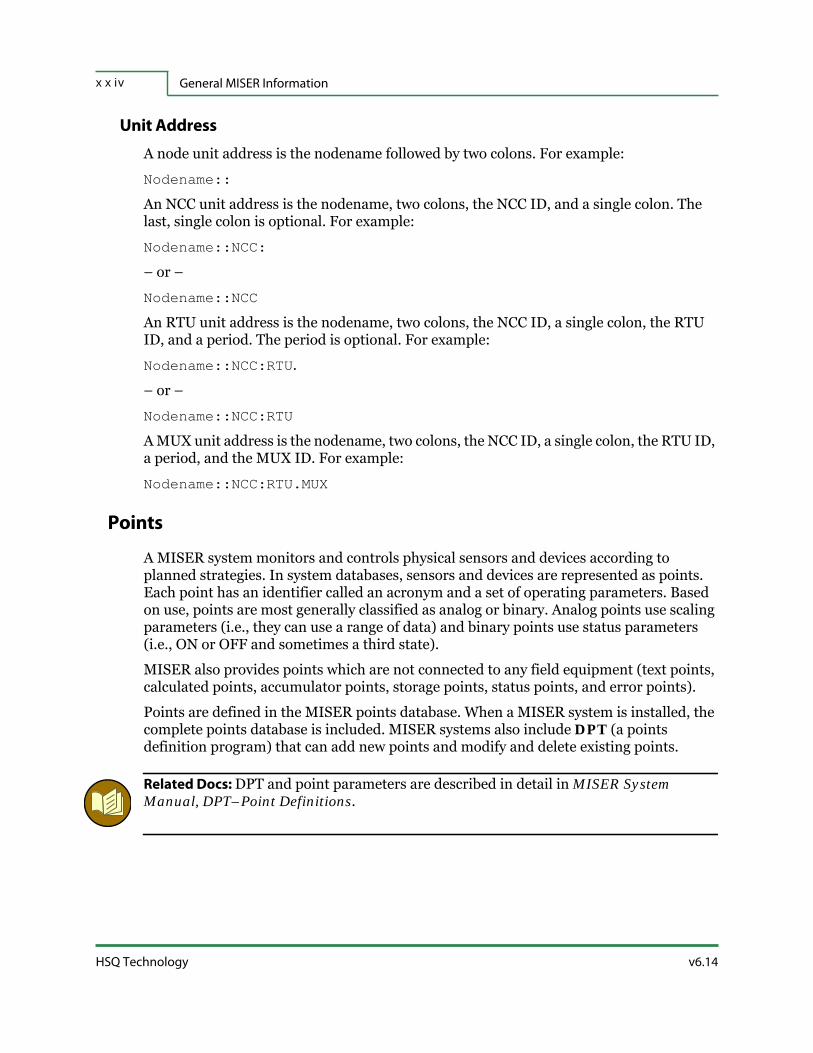
General MISER Informationx x i v
HSQ Technology v6.14
Unit Address
A node unit address is the nodename followed by two colons. For example:
Nodename::
An NCC unit address is the nodename, two colons, the NCC ID, and a single colon. The last, single colon is optional. For example:
Nodename::NCC:
– or –
Nodename::NCC
An RTU unit address is the nodename, two colons, the NCC ID, a single colon, the RTU ID, and a period. The period is optional. For example:
Nodename::NCC:RTU.
– or –
Nodename::NCC:RTU
A MUX unit address is the nodename, two colons, the NCC ID, a single colon, the RTU ID, a period, and the MUX ID. For example:
Nodename::NCC:RTU.MUX
Points
A MISER system monitors and controls physical sensors and devices according to planned strategies. In system databases, sensors and devices are represented as points. Each point has an identifier called an acronym and a set of operating parameters. Based on use, points are most generally classified as analog or binary. Analog points use scaling parameters (i.e., they can use a range of data) and binary points use status parameters (i.e., ON or OFF and sometimes a third state).
MISER also provides points which are not connected to any field equipment (text points, calculated points, accumulator points, storage points, status points, and error points).
Points are defined in the MISER points database. When a MISER system is installed, the complete points database is included. MISER systems also include DPT (a points definition program) that can add new points and modify and delete existing points.
Related Docs: DPT and point parameters are described in detail in MISER System Manual, DPT–Point Definitions.

v6.14 RTU Diagnostics User Manual
Preface x x v
Segmentation and Areas of Responsibility
MISER databases may be portioned into thirty-two separate segments. Operators are assigned one or more of the thirty-two areas of responsibility which parallel database segment assignments. For example, operators that will be working with points assigned to segments 1 and 2 would be assigned to areas of responsibility 1 and 2.
Current database values and all variable parameters are updated only at the computers (network nodes) where the actual database segments reside. (However, the entire points index and all point definitions exist on every network node.) Supervisor workstations are specifically given access to the entire non-segmented database and are automatically updated when any modifications to the points database occurs anywhere on the system.
Segmentation reduces the Change-Of-State (COS) traffic across the network by minimizing the number of messages that need to be sent throughout the network.
Privileged Users and Standard Users
All operators are assigned a security access level. When a command is issued, MISER automatically verifies whether the operator has the authority to do so. Privileged users have access to the entire system and can use any MISER program and access any MISER database. Standard users can access only those MISER programs and databases with access levels equal to or less than their own access assignments.
Each MISER program is assigned a program access level. Each point defined in the points database is assigned a point control level and a point access level. At the start of each action, MISER compares the point access / control level with the command access level and the issuing operator access level. If all levels are compatible, MISER proceeds. If a mismatch occurs, an error results.
Control Ownership
Before carrying out a command, MISER verifies security requirements and then the control ownership status of the point. A select number of MISER programs are assigned priority status according to a preestablished control ownership priority table. All other MISER programs have no priority. Programs with priority status take ownership control of a point. When a point is controlled or owned, it usually cannot be manipulated by another command unless that command has equal or higher priority.
Related Docs: Control ownership is explained in detail in MISER System Manual, Command Processing.

General MISER Informationx x v i
HSQ Technology v6.14
Slides and Targets
In XView, the MISER graphic interface, schematic drawings called slides present static and dynamic objects. Static objects establish a frame of reference. Dynamic objects, called targets provide a link with other slides (page targets), with MISER and non-MISER commands (command targets) and with field activity (point targets). Point targets may move, change color and shape, and blink to reflect real time events. In addition, they provide direct access to selected MISER controls.
Related Docs: Slides and targets are described in MISER Operator Manual,XView Graphical User Interface.

1 - 1v6.14 RTU Diagnostics User Manual
S E C T I O N 1
INSTALLATION AND STARTUP
The Windows version of RTU Diagnostics is similar to the earlier MS-DOS version. As a major enhancement to the software, the communication routines were overhauled so they would integrate fully with the Windows Operating System.
This section details:
Introduction
Installation Guidelines
Starting RTU Diagnostics

Introduction1 - 2
HSQ Technology v6.14
1.1 | Introduction
Minimum system requirements:
Windows compatible PC
512 MB memory
500 MB storage
One serial or Ethernet port
Video adapter
Microsoft® Windows® 95/98/NT/XP/Vista/Windows 7/Windows 10
Required: For proper operation, the RTU Diagnostics software must be run in an MS-DOS console window within Microsoft Windows.
Refer to “Starting RTU Diagnostics” on page 1-8 for detailed information on running RTU Diagnostics software in a Windows environment.
FYI: Throughout the RTU Diagnostics User Manual, “HSQ-6000”, “6000/1911”, and “6000” are used universally for any 6000, 1911, or 1110 RTU.

v6.14 RTU Diagnostics User Manual
Installation and Startup 1 - 3
1.2 | Installation Guidelines
1.2.1 | RTU/PC Connection
An HSQ supplied cable connects the RTU being tested to the computer running the RTU Diagnostics software.
To connect the RTU to the diagnostic computer, attach the cable to the connector on the 2500 RTU or one of the 9-pin serial ports on the 25x86 or 6000 RTU, then connect the other end of the cable to a serial port on the diagnostic computer. If the RTU is equipped with an Ethernet port, that can also be used to make the connection.
Information on connecting an HSQ 25x86 RTU and a laptop is described in Appendix B, “Special Diagnostics Modes”.
1.2.2 | Software Installation
To install the complete suite of the RTU Diagnostics software, use a command window in Windows.
FYI: The RTU Diagnostics software is a stand-alone executable file. If you want only the latest version, it can be downloaded from www.hsq.com/rtudiag/. To replace an older version in a complete installation, navigate to the root of the C: drive (e.g., C:\RTU\RTUDiag) and copy the new version of RTUDiag.exe to that folder.
1.2.2.1 | Windows Installation
The following steps will take you through the installation procedure.
1. Insert the CD containing the RTU Diagnostics software into the CD-ROM drive of the computer you will be using to test and configure your RTU.
2. Open a command window. For Windows XP, this is: Start>Run>cmd. For later versions of Windows, this is: Start>cmd.
3. Navigate to the CD drive and install the software by typing INSTALL. In the example below, the drive letter for the CD-ROM is D, this may not be the case with your system.
C:> D:
D:>INSTALL D: C:
4. Press the <Enter> key and the installer program will display the following text:

HSQ Technology v6.14
Installation Guidelines1 - 4
Figure 1-1. Install.BAT in an MS-DOS Window
5. At this point, you may cancel the installation by pressing <c>, or continue with the installation by pressing any other key. If you continue with the installation, a new folder will be created (C:\RTU\RTUDIAG) and the necessary files will be transferred to the computer’s hard drive. In the above example, the source drive was D: and destination drive was C:. Ensure that the source and destination drive syntax is correct.
See “Starting RTU Diagnostics” on page 1-8 for more details concerning startup.
1.2.3 | RTU Diagnostics Files
The RTU Diagnostics disc contains program files, data files, and batch files to perform specialized functions.
1.2.3.1 | Program Files
The executable program for RTU Diagnostics is rtudiag.exe.
1.2.3.2 | Data Files
In addition to the program file, the files listed in the table below may be created during a program session and used in future test sessions. RTU Diagnostics automatically appends the correct extension to the filename entered. If prompted to enter a filename, do not enter the filename extension.
Table 1-1. RTU Diagnostics PC Files
File Extension Explanation
.BRD File containing configuration for expansion boards (2500/86 only).
.CFA File containing the IP address of a 6000/6200 series module.
.CFC File containing configuration for Port 3 or 4.
.CFG File containing basic configuration data to download to a 2500/86.
.CFI File containing HSQ 6000, 1110, and 1911 Remote I/O (RIO) IP addresses.
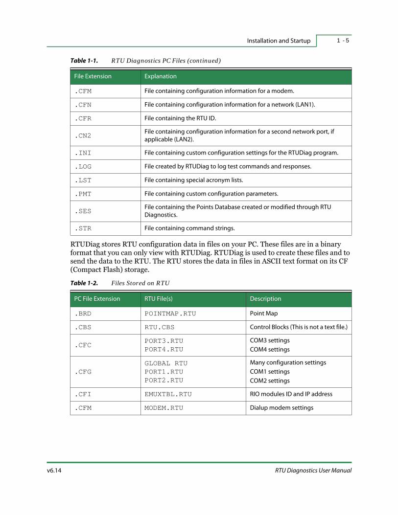
v6.14 RTU Diagnostics User Manual
Installation and Startup 1 - 5
RTUDiag stores RTU configuration data in files on your PC. These files are in a binary format that you can only view with RTUDiag. RTUDiag is used to create these files and to send the data to the RTU. The RTU stores the data in files in ASCII text format on its CF (Compact Flash) storage.
.CFM File containing configuration information for a modem.
.CFN File containing configuration information for a network (LAN1).
.CFR File containing the RTU ID.
.CN2 File containing configuration information for a second network port, if
applicable (LAN2).
.INI File containing custom configuration settings for the RTUDiag program.
.LOG File created by RTUDiag to log test commands and responses.
.LST File containing special acronym lists.
.PMT File containing custom configuration parameters.
.SES File containing the Points Database created or modified through RTU
Diagnostics.
.STR File containing command strings.
Table 1-2. Files Stored on RTU
PC File Extension RTU File(s) Description
.BRD POINTMAP.RTU Point Map
.CBS RTU.CBS Control Blocks (This is not a text file.)
.CFC PORT3.RTUPORT4.RTU
COM3 settings
COM4 settings
.CFGGLOBAL RTUPORT1.RTUPORT2.RTU
Many configuration settings
COM1 settings
COM2 settings
.CFI EMUXTBL.RTU RIO modules ID and IP address
.CFM MODEM.RTU Dialup modem settings
Table 1-1. RTU Diagnostics PC Files (continued)
File Extension Explanation
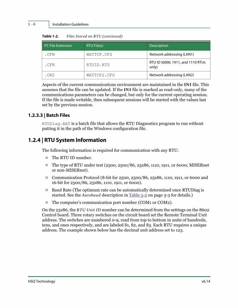
Installation Guidelines1 - 6
HSQ Technology v6.14
Aspects of the current communications environment are maintained in the INI file. This assumes that the file can be updated. If the INI file is marked as read-only, many of the communications parameters can be changed, but only for the current operating session. If the file is made writable, then subsequent sessions will be started with the values last set by the previous session.
1.2.3.3 | Batch Files
RTUDiag.BAT is a batch file that allows the RTU Diagnostics program to run without putting it in the path of the Windows configuration file.
1.2.4 | RTU System Information
The following information is required for communication with any RTU:
The RTU ID number.
The type of RTU under test (2500, 2500/86, 25x86, 1110, 1911, or 6000; MISERnet or non-MISERnet).
Communication Protocol (8-bit for 2500, 2500/86, 25x86, 1110, 1911, or 6000 and 16-bit for 2500/86, 25x86, 1110, 1911, or 6000).
Baud Rate (The optimum rate can be automatically determined once RTUDiag is started. See the Autobaud description in Table 3-2 on page 3-3 for details.)
The computer’s communication port number (COM1 or COM2).
On the 25x86, the RTU Unit ID number can be determined from the settings on the 8602 Control board. Three rotary switches on the circuit board set the Remote Terminal Unit address. The switches are numbered 0-9, read from top to bottom in units of hundreds, tens, and ones respectively, and are labeled S1, S2, and S3. Each RTU requires a unique address. The example shown below has the decimal unit address set to 123.
.CFN WATTCP.CFG Network addressing (LAN1)
.CFR RTUID.RTU RTU ID (6000, 1911, and 1110 RTUs
only)
.CN2 WATTCP2.CFG Network addressing (LAN2)
Table 1-2. Files Stored on RTU (continued)
PC File Extension RTU File(s) Description

v6.14 RTU Diagnostics User Manual
Installation and Startup 1 - 7
Figure 1-2. RTU Address Switches
If you are connecting to a 1110, 1911, or 6000 RTU and the RTU ID has never been set, the default is 32001. If the RTU has previously had its ID set, use 32002 to read the ID from the RTU.
See the RTU ID description in Table 3-2 on page 3-3 for details.
Related Docs: For more information on HSQ Communication Protocols, refer to MISER Technical Reference Manual, HSQ 8-Bit Protocol and HSQ 16-Bit Protocol.
1.2.4.1 | RTU Notes
The RTU makes a chirping sound when a successful Ethernet connection is made. The sound consists of one lower-pitched tone for reception and one higher-pitched sound for reply.
Warning: The RTU makes a buzzing sound while the Solid State Disk (SSD) is being accessed, do not turn off or reset the RTU at this time.
You can expect to hear the buzzing sound when:
The RTU is first started.
When a successful configuration is completed.
After a Point Map is downloaded.

Starting RTU Diagnostics1 - 8
HSQ Technology v6.14
1.3 | Starting RTU Diagnostics
1.3.1 | Windows RTU Diagnostics Startup
Navigate to the location where you installed rtudiag.exe (typically, C:\RTU\RTUDIAG\rtudiag.exe) and double-click the executable to launch the program.
Required: If you are using RTU Diagnostics on a computer with a Windows Vista, Windows 7, or Windows 10 operating system, you must run it as Administrator. Right-click the executable (rtudiag.exe) and select Run as administrator from the menu.
1.3.2 | RTU Diagnostics Configuration
Configuration refers to the selection of communication protocols and RTU Diagnostics settings required to test the attached RTU.
Configuration parameters can be modified using the Config… menu commands. Refer to Section 3, “Configuration Menu” for details.
1.3.3 | Custom Startup
If you save an RTU configuration to a file, then you can recall it when starting another session.
When you terminate RTU Diagnostics, the active configuration is saved on exit in place of the factory default settings in a file called RTUDIAG.INI and can be used as a default configuration for the next session. The configuration data is not saved if the RTUDIAG.INI file is marked as read-only. Below is an example of an RTUDIAG.INI file.
rtu_id 142ncc_id 1node_id 111BCCmisernet 1auto_file_update 0max_cbs 256max_frame_length_8 255max_frame_length_16 255baud_rate 9600port 100autorepeatscroll 1RTS_control 0frontporch 0.0backporch 5.0cmd_size 1cos_time_stamp 1
v6.14 RTU Diagnostics User Manual
Installation and Startup 1 - 9
rtu_type 2output_cos 0linmon 0retries 0
If you have created a custom configuration file, you can load it by following the instructions above and adding the filename to the end of the string. For example if you created a special configuration file named SPECIAL.INI you would enter:
C:\>cd RTU\RTUDIAGC:\RTU\RTUDIAG>RTUDIAG SPECIAL
You do not need to use the INI extension when running RTUDiag in this way. This will load the program file, points database (if available), and the configuration specified in the custom configuration file.

Starting RTU Diagnostics1 - 1 0
HSQ Technology v6.14

2 - 1v6.14 RTU Diagnostics User Manual
S E C T I O N 2
OVERVIEW
The RTU Diagnostics software is used to test and configure HSQ RTUs in MISERnet or non-MISERnet mode, using a standard laptop (or desktop) computer.
The computer connects to the local RTU using the supplied cable. For the 25x86 RTU, virtually any null-modem cable will work. In the cases of the 1110, 1911, and 6000 RTUs, connections are made via Ethernet cable.
FYI: Throughout this manual, references are made to using acronyms. This feature is only available if you have manually entered and saved point definitions with their acronyms. Typically, this is never done and only point numbers are used when working with RTUDiag. If you are only working with point numbers, you can ignore descriptions that discuss using acronyms. Refer to “Defining Points” on page 7-8 for more details.
Quick links to headings in this section:
RTU Diagnostics Basics
Using the Keyboard
Command Processing
Command Menu Commands

RTU Diagnostics Basics2 - 2
HSQ Technology v6.14
2.1 | RTU Diagnostics Basics
Once RTUDiag is started, additional communications and operating parameters are made available for customizing applications. It can also echo activity to an online printer and/or write the same data to a file.
Figure 2-1. RTU Diagnostics Main Menu Window
RTU Diagnostics opens with a Main Menu screen that is divided into four windows: the Title Block, the Command Menu, the Previous Commands, and the Responses windows. To access the online help for any of the functions or commands, press <Alt-h> to open the Help window.
When you start the RTU Diagnostics utility, it displays a text-based user interface you can use to issue test commands and show test results. The tests read and modify point values, display and set the current status, as well as upload, modify, and download RTU control blocks. These tests provide the same access to the RTU and its points that is available from the Host computer. Test results display the maximum amount of data possible in each window. If additional room is required, RTU Diagnostics allows you to scroll data forward and backward. The Host computer can be used to configure point characteristics such as scaling, range, and alarm values.
The RTU Diagnostics utility includes online help, pop-up menus, and automatic prompts when additional information is required. Special keyboard shortcuts move you around the screen, display the time and date, access a calculator, open a log file, start the printer, and expand the response display.
Figure 2-2. RTU Default Settings
The first time you run RTU Diagnostics, the factory default configuration is displayed in the Title Block at the top of the screen.
Title Block
Command Menu
Previous Commands
Responses
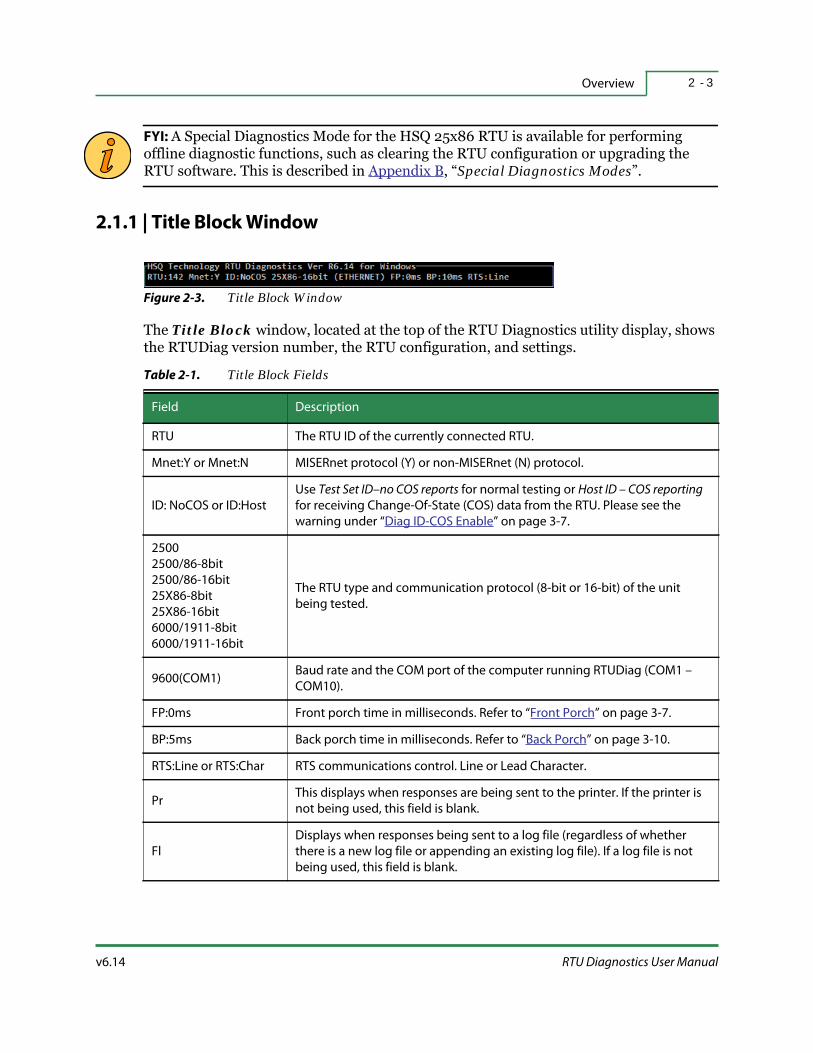
v6.14 RTU Diagnostics User Manual
Overview 2 - 3
FYI: A Special Diagnostics Mode for the HSQ 25x86 RTU is available for performing offline diagnostic functions, such as clearing the RTU configuration or upgrading the RTU software. This is described in Appendix B, “Special Diagnostics Modes”.
2.1.1 | Title Block Window
Figure 2-3. Title Block Window
The Title Block window, located at the top of the RTU Diagnostics utility display, shows the RTUDiag version number, the RTU configuration, and settings.
Table 2-1. Title Block Fields
Field Description
RTU The RTU ID of the currently connected RTU.
Mnet:Y or Mnet:N MISERnet protocol (Y) or non-MISERnet (N) protocol.
ID: NoCOS or ID:Host
Use Test Set ID–no COS reports for normal testing or Host ID – COS reporting
for receiving Change-Of-State (COS) data from the RTU. Please see the
warning under “Diag ID-COS Enable” on page 3-7.
2500
2500/86-8bit
2500/86-16bit
25X86-8bit
25X86-16bit
6000/1911-8bit
6000/1911-16bit
The RTU type and communication protocol (8-bit or 16-bit) of the unit
being tested.
9600(COM1)Baud rate and the COM port of the computer running RTUDiag (COM1 –
COM10).
FP:0ms Front porch time in milliseconds. Refer to “Front Porch” on page 3-7.
BP:5ms Back porch time in milliseconds. Refer to “Back Porch” on page 3-10.
RTS:Line or RTS:Char RTS communications control. Line or Lead Character.
PrThis displays when responses are being sent to the printer. If the printer is
not being used, this field is blank.
Fl
Displays when responses being sent to a log file (regardless of whether
there is a new log file or appending an existing log file). If a log file is not
being used, this field is blank.

RTU Diagnostics Basics2 - 4
HSQ Technology v6.14
2.1.2 | Command Menu Window
The Command Menu window lists the various commands and tests that you can perform on the attached RTU. It is the primary window of the RTU Diagnostics and provides access to all the tests and commands available in the utility.
Figure 2-4. Command Menu Window
At startup, the cursor appears as a highlight over the Repeat command. Tests and commands are selected from the Command Menu window using arrow keys (along with <Enter>), function keys, or shortcut keys. Tests can be issued individually or in strings and can be automatically repeated indefinitely. Testing of field points can be performed one at a time, by range, in groups, or globally, using point parameters read from either the Host or the local RTU database.
Some menu options are followed by an ellipsis (…). This shows that the selection will be followed by a secondary menu. Selections from the secondary menu are made in the same way as those from the Command Menu.
RTU Diagnostics locates points by point number. Some commands (tests) are carried out as soon as they are entered. Others require additional data and open dialog boxes that prompt you for additional information. Numbers and values can be entered in a decimal, hexadecimal, or octal format. The calculator, which can be started at any time (by pressing <Alt-c>), performs base conversions and inserts new values where needed. The program's open design makes it possible to see which test is currently in progress and which tests have preceded the current action.
2.1.3 | Previous Commands Window
The Previous Commands window displays the last eight actions performed.
Figure 2-5. Previous Commands Window

v6.14 RTU Diagnostics User Manual
Overview 2 - 5
Tests can be repeated using the Previous Commands window. This window displays a detailed line history of the last eight commands. The lines are numbered from bottom to top with the latest command at the bottom. Each item listed remembers the parameters used for that command. See “Previous” on page 2-16 for details.
2.1.4 | Responses Window
The Responses window shows tests, echoes selections made from the Command Menu, and displays the associated configuration parameters and settings.
Figure 2-6. Responses Window
Test responses are displayed in the Responses window at the bottom of the screen. In addition to displaying the results, you can configure RTUDiag to log them to a file and/or send the information to a printer. Numeric values are decimal, with the exception of memory values, which are hexadecimal. Normally, the Responses window displays about eight lines. After the window is filled, the lines scroll out of view. However, the Responses window can be scrolled to recall the last one hundred lines at any time (see “Responses Window” on page 2-15).

Using the Keyboard2 - 6
HSQ Technology v6.14
2.2 | Using the Keyboard
Figure 2-7. Cursor Highlight
The cursor appears as a highlighted name in the Command Menu area of the screen and is moved by pressing the arrow keys. To select a command, position the cursor over an item and then press the <Enter> key or the <Spacebar>. Actions can also be performed using the <Tab> key, <Esc> key, shortcut keys, function keys, and hot keys.
Arrow Keys — Moves the cursor in the arrow direction indicated.
Enter/Spacebar — Selects the item that is highlighted.
Tab — On the Main Menu screen, it is used to Poll the RTU with empty frames.
Esc — Moves up one menu level. If you are in the Command Menu window, <Esc> is the same as QUIT.
Shortcut Keys — These are single characters highlighted in each menu item. Pressing a shortcut character moves the cursor to that item and selects it.
Hot Keys — These are single letters paired with the <Alt> key to access specific functions more directly. Press and hold the <Alt> key and then type the appropriate letter. Most hot keys are always available and can be used at any time.
Table 2-2. Hot Key Definitions
Key Description
<Alt-a>
Used for point definitions from the Enter point … prompt. Pressing <Alt-a> opens
the Choose Point dialog box that displays the acronyms for the selected type. This
list is organized alphanumerically, in groups of twelve. To select, highlight a single
acronym, and press <Enter> or the <Spacebar>. Exception: does not have global
application.
This is only for use with points manually defined from within RTU Diagnostics
(using the Save Session Definitions command). If you have not manually entered
and saved point definitions with their acronyms, using this hot key will display the
“No point definitions loaded” message. Typically, this is never used. Refer to
“Defining Points” on page 7-8 for more details.
<Alt-c> Opens the calculator.

v6.14 RTU Diagnostics User Manual
Overview 2 - 7
Function Keys — These are an alternative to selecting options from the menu.
<Alt-d>Opens an MS-DOS prompt. When finished with MS-DOS operations, type EXIT.
FYI: This feature is only available on systems running Windows XP and earlier.
<Alt-f>
Opens the Log File dialog box. Three choices are available, start a new log file, open
an existing file, or close the file. Use the cursor highlight followed by the <Enter> key
or the <Spacebar> to make a selection. To close this box, press the <Esc> key.
Note: These options can also be accessed through Config… on the Command
Menu.
<Alt-h>
Opens the HELP window. There is a general help screen, several context sensitive
help screens, a screen that lists available shortcut keys, and a screen that lists hot
keys. Help is accessible from all windows and dialog boxes.
<Alt-i> Opens an RTU ID window and allows entry of a new RTU ID number.
<Alt-r>Expands the Responses window and opens the Scroll Up/Down dialog box to scroll
through prior responses.
<Alt-u>Opens a list of sensors and sensor values. It also allows you to convert engineering
values and counts for mapping setpoints or defining AIs.
Table 2-3. Function Keys
Function Key Option
<F2> Rspns Win (“Responses Window” on page 2-5)
<F3> Auto Rept (“Repeat” on page 2-14)
<F4> Prev… (“Previous Commands Window” on page 2-4)
<F5> Read AI (“Read Commands” on page 4-2)
<F6> Read DI (“Read Commands” on page 4-2)
<F7> String… (“String” on page 5-2)
<F8> Show…(“Show” on page 5-7)
<F9> Start DV (“Write Commands” on page 4-5)
<F10> Stop DV (“Write Commands” on page 4-5)
<F11> Read DV (“Read Commands” on page 4-2)
<F12> Config… (“Configuration Menu and Commands” on page 3-2)
Table 2-2. Hot Key Definitions (continued)
Key Description

Using the Keyboard2 - 8
HSQ Technology v6.14
2.2.1 | Data Entry
Values, point numbers, etc. can be entered in decimal, hexadecimal, or octal. Ordinary numbers are assumed to be decimal. Numbers starting with 0x are read as hexadecimal (base 16) and numbers starting with 0 are interpreted as octal (base 8). For example, the number 12 (decimal) could also be entered as 0x0C (hexadecimal) or 014 (octal).
At each prompt, type the response and press the <Enter> key. If numbers need to be transposed or you have to do calculations before processing the entry, start the calculator (<Alt-c>) before pressing the <Enter> key. Perform the necessary calculations and then command the calculator to paste the results into the prompt (see “Paste” on page 2-13).
Prompts usually call for a single point number, value, or range. Single point numbers can be the point number or the point acronym. A range is two numbers separated by a hyphen (-) with no additional spaces in between. The range ending value needs to be greater than the range beginning value.
Point acronyms can be substituted for the point number. The <Alt-a> hot key displays a list of acronyms of the appropriate type. Acronyms consist of alphanumeric and other characters (hyphens, underscores, etc.). Within acronyms, RTUDiag recognizes and processes two MISER wildcard characters, the asterisk (*) and the percent sign (%). You can use wildcards to test multiple points through a single command. Refer to “Defining Points” on page 7-8 for limitations of this feature.
2.2.2 | Wildcards
Wildcard characters can be used repetitively in the same search, or at any position (beginning, middle, end) in the point acronym. The asterisk (*) substitutes for zero or more characters at the position entered, to find all acronyms or points matching the search criteria. The percent sign (%) represents one character, at the position entered, to find acronyms or points equal to the quantity used. For example:
ABC* — Finds all acronyms beginning with ABC.
*ABC — Finds all acronyms ending with ABC.
ABC% — Finds four character acronyms beginning with ABC.
%ABC — Finds four character acronyms ending with ABC.

v6.14 RTU Diagnostics User Manual
Overview 2 - 9
2.3 | Command Processing
The following describes command processing and gives a general description of how the RTU Diagnostics program works.
2.3.1 | General Description
Once a command is selected, it may require more information to process your request. If necessary, a secondary dialog box with one or more prompts opens. After the last prompt, the “Sending Command” message displays and the command is shown in the Previous Commands window. Each command is sent to the RTU in a separate frame, and each command response is returned in a separate frame. All responses are displayed in the Responses window.
2.3.2 | Enter Point Number
The most frequently used prompt is “Enter point number (<Alt-A> menu):”. This prompt tells RTU Diagnostics which points should be tested. To return to the Command Menu without executing the command, press the <Esc> key.
RTUDiag searches for one or more points by the point number or acronym. Enter a single point number, a range of point numbers, a single complete point acronym, or a partial point acronym. Point numbers can be entered in decimal, hexadecimal, or octal. Point number ranges must begin with the lower number and end with the higher number. Use a single dash without spaces (e.g., 1-5) to separate the numbers.
2.3.2.1 | Alt-A
Using the hot key combination <Alt-a> opens the Choose Point dialog box. This displays the acronyms for the selected point type (from manually entered acronym definitions) organized alphanumerically in groups of twelve. To make a selection, highlight a single acronym and press <Enter>. Refer to “Defining Points” on page 7-8 for more information and limitations.
Table 2-4. Choose Point Commands
Command Description
QuitReturns to the prompt without selecting a point. The cursor remains at the
Enter point number… prompt, waiting for a response.
MoreDisplays the next page of acronyms. Each display of twelve acronyms is
considered a page.
Acronym NameTwelve acronyms, listed alphanumerically, display on each page. Highlight
an acronym and press <Enter>.

Command Processing2 - 1 0
HSQ Technology v6.14
FYI: If there are no point acronyms defined or loaded from an SES file, this prompt will not do anything.
2.3.2.2 | Additional Prompts
After the Enter point… prompt, some tests or commands require additional prompts.
For example:
Raise DV:Enter point number (<Alt-A> menu) :Enter duration in seconds (0-3276):
Write AI:Enter point number (<Alt-A> menu):Engineering Units or RTU Counts [E|C](E):
Wherever possible, default values are included with the prompt, usually in parentheses.
Ranges of possible values are typically placed in square brackets ([ ]). At each prompt the following functions are available:
Access context-sensitive Help screens — <Alt-h>.
Stop the current test without saving — press <Esc>.
Accept the default — press the <Enter> key or the <Spacebar>.
Enter a new value, followed by pressing <Enter> or the <Spacebar>.
After the last prompt, the message “Sending command...” displays and the command is shown in the Previous Commands window. All responses display in the Responses window and the cursor highlight returns to the top left corner of the Command Menu.
From this point a new test/command may be initiated, RTUDiag may be exited, or the previous command may be reissued.

v6.14 RTU Diagnostics User Manual
Overview 2 - 1 1
2.3.2.3 | Parameter Helper
Some entries require a specific word or initialism.
Figure 2-8. Parameter Helper Example
In these cases, a Parameter Helper dialog box displays in the upper left corner of RTUDiag window with the terms available for use.
2.3.3 | Calculator
The Calculator tool performs integer arithmetic operations in decimal, hexadecimal, and octal number bases, automatically converting values from one base to another. The calculator can be launched at any time, even after you have initiated a test command. Arithmetic operations are specified in Reverse Polish Notation (RPN).
Figure 2-9. RPN Calculator
To activate the Calculator tool, use the hot key <Alt-c>. The calculator window is displayed in the middle of the screen, overlaying the Main Menu screen. The window contains four lines and two columns, providing four accessible levels of Memory and Stack positions. The Memory column is for numbers stored to be used in later calculations and the Stack column is the current working calculation. Basic arithmetic, Boolean, and base conversion functions are all accessible.

Command Processing2 - 1 2
HSQ Technology v6.14
FYI: All operations apply to 16-bit integers only (i.e., numbers between 0 and 65535).
2.3.3.1 | Base Selection
The calculator defaults to the last base used. To switch bases or convert a number from one base to another, enter the first letter of the new base. All numbers in the display field are represented in the current operational number base.
D — Decimal (base 10)
H — Hexadecimal (base 16)
O — Octal (base 8)
2.3.3.2 | Commands
Q — Quit
C — Clear all stack entries
S — Store (maximum of three)
R — Recall from memory
^ — Removes the last entry from the stack
V — Duplicate
X — Exchange (swap) last two stack entries
2.3.3.3 | Operators
& — Boolean AND
| — Boolean OR
~ — Boolean NOT
<< — Shift left
>> — Shift right
+ — Add
- — Subtract
* — Multiply
/ — Divide
% — Modulus

v6.14 RTU Diagnostics User Manual
Overview 2 - 1 3
Required: You must use the standard keyboard (not the numeric keypad) to enter Operators.
2.3.3.4 | Numeral Prefixes
Any individual number or character prefixed by a specific input type, is automatically converted to the operational number base and shown in that number base (e.g., if the operational number base is decimal, 0x23 it will appear as “35” and ‘a will appear as “65” (an apostrophe a, means input the ASCII character a).
2.3.3.5 | Paste
The calculator’s Paste function writes the result of a calculation directly from the calculator screen to a prompt in a dialog box. To use Paste, start a command before starting the calculator. When the prompt requiring the calculation appears on screen, launch the calculator and perform the calculation. When the calculation is complete, press the equal sign (=) on the standard keyboard. The calculator window closes and the calculation result is written to the prompt line.
2.3.3.6 | Calculator Examples
Add two numbers (any base):2 <Enter> 2 + displays “4”
Use the Modulus function:16 <Enter> 5 <Enter> % displays “1”
Store a number in a memory location:228 <Enter> 3S displays “3:228”
Subtract a number from a memory location:1122 <Enter> 3R <Enter> - displays “894”

Command Menu Commands2 - 1 4
HSQ Technology v6.14
2.4 | Command Menu Commands
The commands in the table below are used in the Command Menu to perform specialized screen control tasks.
2.4.1 | Repeat
Figure 2-10. Repeat Command
The Repeat command reissues the last command using the same set of parameters. The last command issued displays at the bottom of the Previous Commands window. If the last command issued was a String…, the string is sent again. Strings are multiple commands linked together and sent as one frame (see “String” on page 5-2 for details).
While Repeat is sending the last command, the RTU response displays in the Responses window. Repeat is not added to the Previous Commands window so it is never considered as the last command. Repeat can be selected multiple times in succession however, if the same command needs to be reissued continuously, it may be more convenient to use the Auto Rept command (refer to “Auto Repeat” on page 2-16).
Table 2-5. Screen Control Commands
Command Description
Repeat Reissues the last command.
Rspns WinOpens a secondary menu window that allows you to scroll the Responses
window.
Auto Rept Continuously repeats a command until another key is pressed.
Prev… Expands the Previous Commands window.
QUIT Terminates RTU Diagnostics.
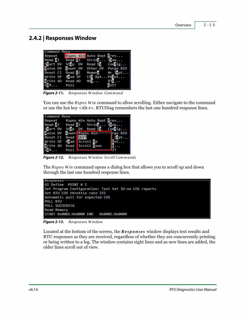
v6.14 RTU Diagnostics User Manual
Overview 2 - 1 5
2.4.2 | Responses Window
Figure 2-11. Responses Window Command
You can use the Rspns Win command to allow scrolling. Either navigate to the command or use the hot key <Alt-r>. RTUDiag remembers the last one hundred response lines.
Figure 2-12. Responses Window Scroll Commands
The Rspns Win command opens a dialog box that allows you to scroll up and down through the last one hundred response lines.
Figure 2-13. Responses Window
Located at the bottom of the screen, the Responses window displays test results and RTU responses as they are received, regardless of whether they are concurrently printing or being written to a log. The window contains eight lines and as new lines are added, the older lines scroll out of view.

Command Menu Commands2 - 1 6
HSQ Technology v6.14
2.4.3 | Auto Repeat
Figure 2-14. Auto Repeat Command
The Auto Rept command continuously reissues the last issued command using the same parameters as before. The last command issued is displayed at the bottom of the Previous Commands window. To stop Auto Repeat, press the <Esc> key. If the last command issued was a String…, Auto Repeat automatically and continuously repeats the string. While Auto Repeat is working, the message Commands sent: and the number of times the command has been sent is displayed. The RTU response displays in the Responses window. There are two options for the AutoRpt Scroll… responses in the RTUDiag Settings:
AutoRepeat Scrolls Response Window — the response lines display in succession and once the window is filled the responses scroll.
AutoRepeat Updates Response Window — the response line only displays when there is a change.
For details, refer to “Auto Repeat Scroll” on page 3-7. Auto Repeat is not added to the Previous Commands window so it is considered the last command.
2.4.4 | Previous
Figure 2-15. Previous Command
Select Prev… by highlighting it and pressing <Enter> or by using the shortcut key <p>.

v6.14 RTU Diagnostics User Manual
Overview 2 - 1 7
Figure 2-16. Expanded Previous Commands Window
When the Previous Commands window is expanded, the line numbers become shortcut keys. To repeat a previous command quickly, type its shortcut key or select it with the cursor. The command is carried out in the same way as before and the response displays in the Responses window.
After a command is executed, it is numbered and added to the list of the most recent eight commands. Each command is written on one line.
FYI: This is true for most, but not all of the test set commands.
2.4.5 | Quit
Figure 2-17. Quit Command
To exit the program, select QUIT from the Command Menu by pressing the <q> key or by using the arrow keys to highlight QUIT and pressing the <Enter> key.

HSQ Technology v6.14
Command Menu Commands2 - 1 8
Figure 2-18. RTU Diagnostics Quit Confirmation Window
RTU Diagnostics displays a dialog box asking you to confirm.
Figure 2-19. RTU Diagnostics Quit Confirmation with Unsaved Points Dialog Window
If points or strings were defined during the last session and have not been saved, RTU Diagnostics replaces the normal prompt with a warning message.
The default response, Cancel, returns to the Command Menu window. Selecting Exit and Lose Definitions quits RTU Diagnostics without saving.
3 - 1v6.14 RTU Diagnostics User Manual
S E C T I O N 3
CONFIGURATION MENU
The Configuration Menu allows you to adjust the settings for the RTU and determine how RTU Diagnostics connects with the RTU. This section describes:
Configuration Menu and Commands
RTU Settings
RTU Diagnostics Settings
Custom Prompts
Save to File
Load from File
QA Test Report

Configuration Menu and Commands3 - 2
HSQ Technology v6.14
3.1 | Configuration Menu and Commands
Figure 3-1. Configuration Command
Figure 3-2. Configuration Sub-Menu
When the Config… command is selected, a secondary menu is displayed. The options are:
Table 3-1. Configuration Menu Commands
Command Description Shortcut Key
QUIT Exits to the Command Menu. <q> or <Esc>
RTU Settings… Opens the RTU Settings tertiary menu. <r>
RTUdiag Settings… Opens the RTUdiag Settings tertiary menu. <d>
Custom PromptsCreates/modifies up to ten different custom prompts for a
custom configuration to download to the RTU.<c>
Save to FileSaves the current RTU configuration parameters file and sets
all the parameters to the values in the file.<s>
Load from FileLoads a customized configuration parameters file and sets all
the parameters to the values in the file.<l>
QA Test Report…
Creates a QA Report containing the job name, project number,
site location, tester’s name, and options for saving to file or
printing.
<a>

v6.14 RTU Diagnostics User Manual
Configuration Menu 3 - 3
3.2 | RTU Settings
Figure 3-3. RTU Settings Command
The RTU Settings… command is used for configuring the connected RTU.
Figure 3-4. RTU Settings Menu
Selecting RTU Settings… displays a third-level menu.
Table 3-2. RTU Settings Menu
Setting Description Shortcut Key
Quit Closes the RTU Settings dialog box. <q>
COS time
This command allows you to configure the Change-Of-State
(COS) timestamp. Select …Yes from the resulting dialog box to
timestamp COS data, otherwise select …No.
N/A
RTU ID
This command prompts you for a new ID number. The current
RTU ID is displayed in the Title Block (e.g., RTU:142). To change
the RTU ID, type a number in the subsequent Entry field and
press <Enter>. To keep the same ID, press <Esc>.
FYI: If you are connected to a 25x86 RTU, this number must
match the rotary switches on the 8602 Control board.
<r>

RTU Settings3 - 4
HSQ Technology v6.14
MISERnet…
This command allows you to configure the RTU
communication protocol. Select …Yes from the resulting
dialog box to use the MISER net protocol, otherwise select
…No. The current protocol is displayed in the Title Block (e.g.,
Mnet:Y).
FYI: Most RTUs use the MISERnet protocol. Some older 2500
RTUs may not.
<m>
RTU Type
This command opens a dialog box that prompts you for the
model of the RTU you are testing. Select from: 2500 Z80,
2500/86, 25X86, or 6000/1911. If 2500/86, 25X86, or 6000/1911
is selected, you must also specify 8 or 16 bit Protocol. The
current RTU Type and protocol is displayed in the Title Block
(e.g., 25X86–16bit).
<t>
Autobaud
This command tells RTUDiag to automatically determine the
correct communication baud rate. Select Quick … or Normal
… from the resulting dialog box. Quick checks only the most
common baud rates, while Normal checks all baud rates.
<a>
NCC ID
This command prompts you to enter the NCC ID of the Host
system.
FYI: This setup option is no longer used.
<n>
Node ID
This command prompts you to enter the Node ID of the Host
system.
FYI: This setup option is no longer used.
<d>
CB Count
This command prompts you to enter the maximum number of
Control Blocks. Enter a number in the subsequent Entry field
and press <Enter>. To keep the same number, press <Esc>.
FYI: The maximum number you can enter for an 8-bit RTU is
255 and the maximum for a 16-bit RTU is 510.
<b>
300 to 57.6k Baud
The right-hand column provides a range for manually setting
the communication baud rate between the RTU and the
testing computer.
Varies
Table 3-2. RTU Settings Menu (continued)
Setting Description Shortcut Key

v6.14 RTU Diagnostics User Manual
Configuration Menu 3 - 5
3.3 | RTU Diagnostics Settings
Figure 3-5. RTUDiag Settings Command
The RTUdiag Settings… command is used for configuring the RTUDiag program.
Figure 3-6. RTUDiag Settings Menu
Selecting RTUdiag Settings… displays a third-level menu. These commands are used to configure the RTU Diagnostics program. These changes take effect immediately and are displayed in the Title Block (where applicable).
FYI: The COM Port…, Line/Lead Char, Front Porch, and Back Porch commands are true Program Communication Parameters; they affect only the computer and not the RTU.
3.3.1 | Printer
Warning: This feature is currently not available. Trying to turn the printer on will cause RTUDiag to close.
3.3.2 | File
The File… command (shortcut key <f>) is used to select the log file status. If the log file is being used, Fl is displayed in the Title Block (e.g., RTS:Line Fl). RTU Diagnostics names the log file DIAG.LOG and saves it in the directory where the RTUDiag executable is kept (e.g., C:\RTU\RTUDIAG). The DIAG.LOG file contains a listing of all activity,

RTU Diagnostics Settings3 - 6
HSQ Technology v6.14
beginning with the date and time the file was opened. If the file is already open, it remains open and receives data until it is closed. The DIAG.LOG file contains any configuration changes, all diagnostic commands, and all responses.
Selecting File… opens a dialog box with three choices:
Start new log file
Open existing log file
Close log file
When a new log file is started, it overwrites any existing log file. To retain a specific log file for future reference, you can append new data to it by selecting Open existing log file or you can copy the old log file to a new location or give it a new name before beginning a new session. The log file remains open until Close log file is selected.
3.3.3 | COM Port
The COM Port… command (shortcut key <c>) allows you to set the PC communication port. The current COM port is displayed in the Title Block (e.g., (ETHERNET)). Selecting this command opens a dialog box that allows you to SET COM1-10 or SET ETHERNET.
COM ports 1 and 2 are typically used for the 9-pin serial connections on the PC. Depending on the configuration of your computer this may not be the case. It may be necessary to determine the correct COM port, especially if you are using a USB-to-serial adapter cable. Open the Device Manager on your PC and view “Ports”.
Selecting SET ETHERNET opens an Entry field where you can input the IP address.
Required: When connecting to the RTU via Ethernet, the PC running RTUDiag must be on the same IP address subnet as the RTU. Contact your Network Administrator for assistance in configuring this.
FYI: Ethernet configuration settings are not saved and must be entered every time RTU Diagnostics is started.
Refer to “Network” on page 6-19 for details on setting the IP address.
3.3.4 | Line/Lead Character
The Line/Lead Char command (shortcut key <l>) is used to select between Direct RTS Line Control and Activate RTS by Leading Character. The … Leading Character option should only be selected if a “dumb” RTS Generator is used to key a radio.

v6.14 RTU Diagnostics User Manual
Configuration Menu 3 - 7
3.3.5 | Front Porch
The Front Porch command (shortcut key <h>) allows you to set the front porch delay in milliseconds (i.e., the delay before a message is transmitted). RTS is on during this time, but no data is sent. This gives RTU Diagnostics the necessary time to stabilize the communication channel between itself and the RTU (typically used for radio links). See “RTS — Request To Send” on page G-4 for a glossary description.
If the PC that is running RTUDiag is wired directly to the RTU, the front porch time is probably not required and can be set to zero. The current delay is displayed in the Title Block (e.g., FP:0ms).
Selecting this command opens an Entry field:
Enter front porch delay in milliseconds:
Enter a number and press <Enter> or <Esc> to keep the current delay.
3.3.6 | Auto Repeat Scroll
The AutoRpt Scroll… command (shortcut key <a>) allows you to configure how data displays in the Responses window. Each time Auto Rept (see “Auto Repeat” on page 2-16 for details) issues a command, an entry is made in the Responses window. There are two options when you select AutoRpt Scroll…:
AutoRepeat Scrolls Response Window — once the Responses window has filled, it will scroll with new entries. The Responses window can be expanded later and you may recall responses that have moved out of view.
AutoRepeat Updates Response Window — once the Responses window has filled, the last response will be overwritten by the current response.
3.3.7 | Diag ID-COS Enable
The Diag ID-COS enable command (shortcut key <s>) allows you to enable or disable COS reporting from the RTU to RTUDiag. The current setting is displayed in the Title Block (e.g., ID:NoCOS). The options are:
Test Set ID-no COS reports — used for normal operation.
Host ID - COS reporting — used only for special testing.
Normally, RTUDiag uses an ID that is different from the Host ID and the RTU will not send COS reports to RTUDiag. If RTUDiag uses the Host ID, the RTU will send COS reports to RTUDiag. These COS reports are not sent to the real Host.
Warning: When Host ID is enabled, the RTU will assume that RTUDiag is the Host and send all COS data to it, clearing the buffer. This means that the real Host will not receive the COS data and it will be lost.

RTU Diagnostics Settings3 - 8
HSQ Technology v6.14
3.3.8 | Device Ownership
The Device Ownrship command (shortcut key <d>) allows you to set the device control bit. The options are:
Set Device Ownership
No Device Ownership
When this bit is set, some commands (e.g., Start DV, Stop DV, etc.) will prompt you to enter the control level bit. Many MISER functions and calculated events assume control or ownership of a point while the command is being carried out. A function cannot immediately override the action being performed. It does so by setting a bit in the point’s control/ownership word, according to a preestablished priority level.
If two or more functions want to command the same point, the function with the highest priority level succeeds. PSR and PST have priority over all other functions. Either function can interrupt current processing to carry out its own control instruction.
Warning: Improperly changing this may cause an operator lockout. The range of values is 3-14 with 3 being low and 14 high. If control ownership is set too high, it can override the Host.
Related Docs: Control ownership is explained in detail in MISER Operator Manual, Control Ownership and MISER System Manual, Command Processing. You should consult this document before changing this parameter.
Table 3-3. Control Ownership Levels
MISER Program / Command Control Ownership Level
Privileged Start/Stop (PSR and PST) Level 14 – Highest Control Level (Priority)
Clearance Tag (C) Level 12
Hot Line Tag (B) Level 11
Special Condition Tag (A) Level 10
Power Demand Limiting Level 9
Duty Cycle Level 7
Optimum Stop/Start Level 6
Boiler/Chiller Level 5
Calculated Event with Low Priority Level 3 Lowest Control Level

v6.14 RTU Diagnostics User Manual
Configuration Menu 3 - 9
3.3.9 | Poll Expected COS
The Poll Expected COS command (shortcut key <x>) determines whether COS information from the RTU should be returned automatically or only in response to a query. The options are:
Auto poll for expected COS — automatically retrieves COS information from the RTU.
Command poll only — retrieves COS information from the RTU only when it is manually polled (similar to using <Tab>).
3.3.10 | Frame Sequence Automatic Increment
The Frame Seq Auto Inc command (shortcut key <e>) configures the RTU/PC frame communication numbers. The options are:
Auto Frame Sequence Increment — sets the attached frame to automatically cycle through its allowable range for testing purposes.
Fixed Frame Sequence — gives the communication frame the same number repeatedly.
See “Frame” on page G-2 for a glossary description.
3.3.11 | CBM file update
The CBM file update command (shortcut key <t>) lets you define the file update mode. The options are:
Update active file automatically — saves the active Control Block file on exit from the Modify screen whenever a change has been made to the displayed Control Block.
Explicit file saves only — specifies that the active Control Block is only saved when the Save to File command is used.
3.3.12 | Max Frame Length
The Max Frame Length command (shortcut key <r>) is used to configure the maximum allowable PC frame length during PC/RTU communications.
Figure 3-7. Maximum Frame Length
The maximum value is 255 regardless of whether you are using an 8-bit or 16-bit RTU. For all systems, except those that can only handle very short data bursts, 255 is used.

RTU Diagnostics Settings3 - 1 0
HSQ Technology v6.14
3.3.13 | Back Porch
The Back Porch command (shortcut key <b>) allows you to set the back porch delay in milliseconds (i.e., the delay after a message is transmitted). RTS is on during this time, but no data is sent. This delay is typically used to allow the last one or two bytes of the RTU transmission to be safely sent by the RTU and radio hardware combination.
If the PC that is running RTUDiag is wired directly to the RTU, the back porch time is probably not required and can be set to 20 ms. The current delay is displayed in the Title Block (e.g., BP:5ms).
Selecting this command opens an Entry field:
Enter back porch delay in milliseconds:
Enter a number and press <Enter> or <Esc> to keep the current delay.
3.3.14 | Line Monitor
The Line Monitor command (shortcut key <m>) sets the RTUDiag program to analyze incoming and outgoing data on the serial port.
Figure 3-8. Interleaved Data
Figure 3-9. Separate Lines Data
The options are:
Interleaved Display — sequentially displays data packets across two lines. Text with a dark background and light letters is data sent to the RTU from RTUDiag and text with light background and dark letters is data sent to RTUDiag from the RTU.
Line Monitor Off — turns line monitoring off.
Separate Lines — configures data to and from the RTU to display on separate lines. The top line is data sent to the RTU and bottom line is data sent to RTUDiag.
3.3.15 | Retries
The Retries command (shortcut key <i>) allows other commands to be retried automatically a specified number of times. This command is usually applied when communication lines are subject to noise or errors.

v6.14 RTU Diagnostics User Manual
Configuration Menu 3 - 1 1
Selecting this command opens an Entry field:
Enter retries number:
Enter a number and press <Enter> or <Esc> to keep the current delay.
Custom Prompts3 - 1 2
HSQ Technology v6.14
3.4 | Custom Prompts
Ten different site-specific, application dependent values can be defined and saved in a PMT file for use as custom configuration parameters. For custom configuration parameter settings, refer to “Configuration Parameters – Custom” on page 6-14. Selecting the Custom Prompts command (shortcut key <c>) displays the prompt:
Load from file name [PROMPTS]:If a PMT file does not already exist, press <Esc> to enter the Custom Prompts screen. This opens the Entry field:
Custom Prompt 1 (Custom_Param_1):Enter custom prompts as desired. Pressing <Enter> accepts the default displayed (i.e., the name between the parentheses). Pressing <Esc> at any point will exit without saving the parameters. After the tenth prompt has displayed, RTU Diagnostics will ask you to save the information to a file:
Save to file name[PROMPTS]:Enter a file name. The T file extension is automatically added when the file is saved. The file is stored in the current working directory.

v6.14 RTU Diagnostics User Manual
Configuration Menu 3 - 1 3
3.5 | Save to File
The Save to File command (shortcut key <s>) allows you to save the current configuration parameters to a file. Selecting the Save to File command opens an Entry field:
File name:
You do not need to add the INI extension; it is added automatically once you save the file.

Load from File3 - 1 4
HSQ Technology v6.14
3.6 | Load from File
The Load from File command (shortcut key <l>) allows you to load a saved configuration file (INI) that contains customized parameters. Selecting the Load from File command opens an Entry field:
File name:You do not need to add the INI extension.
Refer to “RTU Diagnostics Files” on page 1-4 for additional information on program files, data files, and batch files designations.

v6.14 RTU Diagnostics User Manual
Configuration Menu 3 - 1 5
3.7 | QA Test Report
Warning: This is typically only used by the factory. Parameters here should not be changed in the field.
The QA Test Report… command (shortcut key <a>) inserts header information into a generated report that lists the current RTU configuration settings. Choosing an option opens a window that prompts for additional information. When File is selected, you are given a prompt for additional information; enter a name for the report. The created file will have a.DOC extension and may be located in the default RTU directory (C:\RTU\RTUDIAG). It can be viewed using any ASCII text editor or other word processing program and then subsequently printed.
FYI: If RTUDiag is launched from a directory other than the default, the QA Test Report will be saved in that folder (i.e., the folder that contains the RTUDiag.exe file).

QA Test Report3 - 1 6
HSQ Technology v6.14

4 - 1v6.14 RTU Diagnostics User Manual
S E C T I O N 4
DIAGNOSTIC COMMANDS
RTU Diagnostics reads and writes values and determines the status of individual points and devices. RTUDiag tests points and devices singly and in groups, by point number or by the database acronym. It can issue commands individually or by String.
Tests and commands are issued from the main Command Menu window. The RTU Diagnostics commands can be subdivided into Read, Write, Status, RTU menu, and Point menu commands.
This section describes procedures for testing points and devices, defining a points database, and defining board and RTU configurations. It includes descriptions for the following:
Read Commands
Write Commands
Status Commands – Other DV
Status Commands – COS Report
Status Command – MUX

Read Commands4 - 2
HSQ Technology v6.14
4.1 | Read Commands
Read commands display point values / device states.
Warning: Performing the Poll command during diagnostics (Host ID mode) will prevent the MISER Host from receiving the data and consequently it will not be saved to the permanent database. Refer to “Poll” on page 4-3 for more information.
Each time a Read command is issued, it is sent to the RTU in a separate frame. To send multiple commands in a single frame use the String… command (refer to “String” on page 5-2). Read commands (except for Memory) begin by prompting for the point number or acronym. To continue, enter a single point number, a range of point numbers, a single point acronym, or a partial acronym with wildcard characters.
Point numbers can be entered in decimal, hexadecimal, or octal. Point number ranges consist of two point numbers separated by a dash (-). The ending point number must be greater than the beginning point number. Do not use blank spaces on either side of the dash.
To locate points by acronym, use the hot key combination <Alt-a>. This opens the Choose Point dialog box and displays all the acronyms for the selected point type. The list shows the first group of twelve and is organized alphanumerically. Selecting More (shortcut key <m>) displays the next page of acronyms. Select the acronym and it is added to the prompt and the test is executed. Refer to “Defining Points” on page 7-8 for limitations of this feature.
Table 4-1. Read Commands
Command Description Shortcut Key
Read AI Displays analog inputs. <a>
Read DI Displays digital inputs. <d>
Read DV Displays the last command issued to a device. <v>
Read CI Displays the number of pulses since the last reset. <c>
Memory Reads the RTU memory (also writes to memory). <y>
Read SP Displays the current setpoint value. <e>
Read AO Displays the last value sent to an analog output. N/A
Poll Requests RTU command responses or COS information in the
buffer that is awaiting transmission.<Tab>
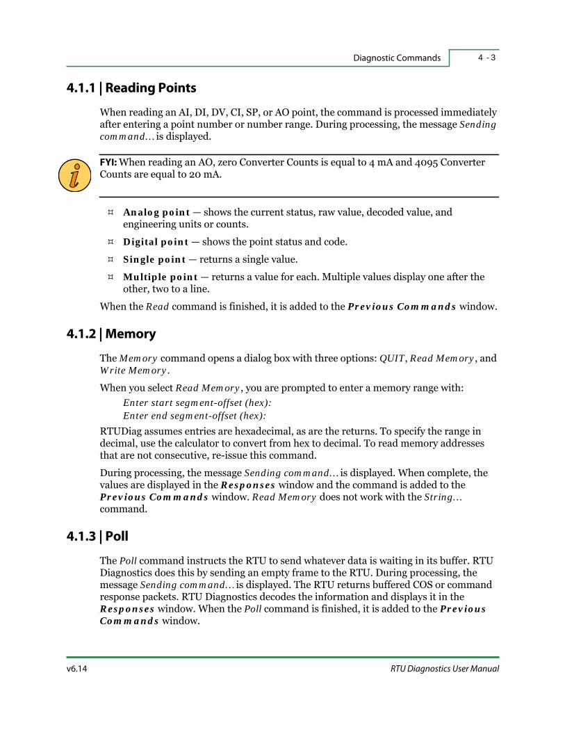
v6.14 RTU Diagnostics User Manual
Diagnostic Commands 4 - 3
4.1.1 | Reading Points
When reading an AI, DI, DV, CI, SP, or AO point, the command is processed immediately after entering a point number or number range. During processing, the message Sending command… is displayed.
FYI: When reading an AO, zero Converter Counts is equal to 4 mA and 4095 Converter Counts are equal to 20 mA.
Analog point — shows the current status, raw value, decoded value, and engineering units or counts.
Digital point — shows the point status and code.
Single point — returns a single value.
Multiple point — returns a value for each. Multiple values display one after the other, two to a line.
When the Read command is finished, it is added to the Previous Commands window.
4.1.2 | Memory
The Memory command opens a dialog box with three options: QUIT, Read Memory, and Write Memory.
When you select Read Memory, you are prompted to enter a memory range with:Enter start segment-offset (hex):Enter end segment-offset (hex):
RTUDiag assumes entries are hexadecimal, as are the returns. To specify the range in decimal, use the calculator to convert from hex to decimal. To read memory addresses that are not consecutive, re-issue this command.
During processing, the message Sending command… is displayed. When complete, the values are displayed in the Responses window and the command is added to the Previous Commands window. Read Memory does not work with the String… command.
4.1.3 | Poll
The Poll command instructs the RTU to send whatever data is waiting in its buffer. RTU Diagnostics does this by sending an empty frame to the RTU. During processing, the message Sending command… is displayed. The RTU returns buffered COS or command response packets. RTU Diagnostics decodes the information and displays it in the Responses window. When the Poll command is finished, it is added to the Previous Commands window.

Read Commands4 - 4
HSQ Technology v6.14
The Diag ID-COS enable command must be set to Host ID - COS reporting for this command to work properly (refer to “Diag ID-COS Enable” on page 3-7 for more details). Otherwise, the COS data is not sent and the error message RTU COS TRANSMISSION DISABLED – NON–HOST TESTSET ID is displayed. However, in the Responses window, POLL SUCCESSFUL is shown in either case.

v6.14 RTU Diagnostics User Manual
Diagnostic Commands 4 - 5
4.2 | Write Commands
Write commands change point values / device states.
Warning: Performing these commands during diagnostics (Host ID mode) will not send the data to the MISER Host and consequently it will not be saved in the permanent database. Refer to “Diag ID-COS Enable” on page 3-7 for more information.
Each time a Write command is issued, it is sent to the RTU in a separate frame. To send multiple commands in a single frame use the String… command (refer to “String” on page 5-2). Write commands (except for Memory) begin by prompting for the point number or acronym. To continue, enter a single point number, a range of point numbers, a single point acronym, or a partial acronym with wildcard characters.
Point numbers can be entered in decimal, hexadecimal, or octal. Point number ranges consist of two point numbers separated by a dash (-). The ending point number must be greater than the beginning point number. Do not use blank spaces on either side of the dash.
To locate points by acronym, use the hot key combination <Alt-a>. This opens the Choose Point dialog box and displays all the acronyms for the selected point type. The list shows the first group of twelve and is organized alphanumerically. Selecting More (shortcut key <m>) displays the next page of acronyms. Select the acronym and it is added to the prompt and the test is executed. Refer to “Defining Points” on page 7-8 for limitations of this feature.
Table 4-2. Write Commands
Command Description Shortcut Key
Start DV Turns a device ON. <t>
Stop DV Turns a device OFF. <o>
Raise DV Pulses a raise output. <r>
Lower DV Pulses a lower output. <l>
Reset CI Displays and resets counter inputs. N/A
Memory Writes values to the RTU memory (also reads memory). <y>
Wr Inpt… Writes values to AIs and DIs. <n>
Write SP Changes setpoint values. N/A
Write AO Changes analog output. <w>

Write Commands4 - 6
HSQ Technology v6.14
4.2.1 | Start DV / Stop DV
When starting or stopping a device, the command is processed immediately after entering a point number or number range. During processing, the message Sending command… is displayed and verification of the action is shown in the Responses window. If a single point is started/stopped, only one verification is shown. If a range of points is started/stopped a verification is shown for each point. Multiple verifications display one after the other, two to a line.
Related Docs: For a more detailed explanation of DV commands, please refer to 25x86 Logic Processor User Manual, Device Table.
4.2.2 | Raise DV / Lower DV
When a Raise DV or Lower DV command is selected, you are prompted to enter a pulse duration of zero to 3276 seconds.
During processing, the message Sending command… is displayed and verification of the action is shown in the Responses window. If a single point is raised/lowered, only one verification is shown. If a range of points is raised/lowered, a verification is shown for each point. Multiple verifications display one after the other, two to a line.
The MISER commands RAI and LOW raise and lower outputs for points defined with the output subtype, “Raise/Lower”. Points can be raised or lowered for a duration of up to 255 units for 8-bit RTUs and 65535 units for 16-bit RTUs. Typically, a unit is one tenth of a second. This is an incremental increase.
Related Docs: For a more detailed explanation of Raise/Lower commands, please refer to MISER Operator Manual, RAI & LOW - Raise/Lower Point.
4.2.3 | Reset CI
A Counter Input is used to track values over a period of time. The Reset CI command is used to zero out the counter and begin tracking again.
The Reset CI command is processed immediately after entering a point number or number range. During processing, the message Sending command… is displayed and verification of the action is shown in the Responses window. If a single point is reset, only one verification is shown. If a range of points is reset a verification is shown for each point. Multiple verifications display one after the other, two to a line.

v6.14 RTU Diagnostics User Manual
Diagnostic Commands 4 - 7
4.2.4 | Memory
The Memory command opens a dialog box with three options: QUIT, Read Memory, and Write Memory.
When you select Write Memory, you are prompted with:Enter start segment-offset (hex):
Enter the starting memory address in hexadecimal. The address is then displayed and the blinking cursor prompts for data to write to that address. Entering data and pressing <Enter> increments the address by one. The first null response (no data input) signals that the command is ready to be sent. To send data to memory addresses that are not consecutive, reissue this command or use the String… command.
During processing, the message Sending command… is displayed. When complete, the values are displayed in the Responses window and the command is added to the Previous Commands window.
FYI: This command is only valid for 16-bit RTUs.
4.2.5 | Write Input
The Wr Inpt command opens a dialog box with three options: QUIT, Write AI, and Write DI. Values written to hardware points are overwritten during the next hardware scan.
Best Practices: Write DI should only be used for virtual points (e.g., those points that do not have a hardware input).
During processing, the message Sending command… is displayed and verification of the action is shown in the Responses window. If writing to a single point, only one verification is shown. If writing a range of points, verification is shown for each point. Multiple verifications display one after the other, two to a line. For proper scaling of engineering units, the point must first be defined using the AI Define and DI Define commands (see “AI Define” on page 7-8 and “DI Define” on page 7-11 for more information).

Write Commands4 - 8
HSQ Technology v6.14
4.2.5.1 | Writing To an Analog Input
Figure 4-1. Write AI Prompts
Begin by entering the point number or acronym. The next prompt asks you to enter Engineering Units [E] or RTU Counts [C].
If <E> is entered, the following prompt is displayed:Enter analog in value (Percent):
If <C> is entered, the following prompt is displayed:Enter analog in value (Counts):
4.2.5.2 | Writing To a Digital Input
Figure 4-2. Write DI Prompts
Begin by entering the point number or acronym. The next prompt asks you to enter either 0 or 1 for the DI state.
4.2.6 | Write SP / Write AO
Begin by entering the point number or acronym to write to. The next prompt asks you to enter Engineering Units [E] or RTU Counts [C]. If <E> is selected, the point must first be defined using the SP Define and AO Define commands (see “SP Define” and “AO Define” on page 7-12 for more information). This ensures that the engineering units are consistent with Converter Counts.
For Write SP, enter the setpoint out value.
For Write AO, enter the analog out values (mA).
To continue, enter the new setpoint or analog output value.
FYI: When writing an AO, zero Converter counts is equal to 4 mA and 4095 Converter Counts are equal to 20 mA.

v6.14 RTU Diagnostics User Manual
Diagnostic Commands 4 - 9
4.3 | Status Commands – Other DV
Each status command opens a dialog box with a menu of options. Device (DV) commands are sent to the RTU in a separate frame. To send multiple commands in a single frame, use the String… command (see “String” on page 5-2 for details).
When the Other DV command is selected, there are more options available for selection.
All Other DV commands begin by prompting for the point number or acronym. To continue, enter a single point number, a range of point numbers, a single point acronym, or a partial acronym with wildcard characters.
Point numbers can be entered in decimal, hexadecimal, or octal. Point number ranges consist of two point numbers separated by a dash (-). The ending point number must be greater than the beginning point number. Do not use blank spaces on either side of the dash.
To locate points by acronym, use the hot key combination <Alt-a>. This opens the Choose Point dialog box and displays all the acronyms for the selected point type. The list shows the first group of twelve and is organized alphanumerically. Selecting More (shortcut key <m>) displays the next page of acronyms. Select the acronym and it is added to the prompt and the test is executed. Refer to “Defining Points” on page 7-8 for limitations of this feature.
4.3.1 | Flash DV
Begin by entering the point number or acronym, the following prompt is then displayed:Enter duration in seconds (0-3276):
The duration determines the length of the pulse. During processing, the message Sending command… is displayed and verification of the action is shown in the
Table 4-3. Other DV Commands
Command Description Shortcut Key
QUIT Exits to the Command Menu. <q> or <Esc>
Flash DV Pulses a device repeatedly. <f>
Release DV Releases the point control / ownership bit. <r>
Select DV Selects a device. <s>
Enable DV Enables COS for a device. <b>
Disable DV Disables COS for a device. <d>
Select DV for Start Selects the device to start. <t>
Select DV for Stop Selects the device to stop. <o>

Status Commands – Other DV4 - 1 0
HSQ Technology v6.14
Responses window. If flashing a single point, only one verification is shown. If flashing a range of points, verification is shown for each point. Multiple verifications display one after the other, two to a line.
This command continues indefinitely until a Pulse Duration value of zero (or Start DV, Stop DV, Raise DV, or Lower DV command) is issued.
Related Docs: For additional information on Flash DV, refer to MISER Technical Reference Manual, Flash DV.
4.3.2 | Release DV
The Release DV command sends the RTU control ownership for a device without issuing a Start/Stop command.
Related Docs: For additional information on RTU control ownership, refer to MISER Technical Reference Manual, Release DV.
Begin by entering the point number or acronym, the following prompt is then displayed:Enter control bit(0-15):
Enter the value for the control level bit to release. This command is typically used after a Start DV or Stop DV command that set the control/ownership bit. During processing, the message Sending command… is displayed and verification of the action is shown in the Responses window. If releasing a single point, only one verification is shown. If releasing a range of points, verification is shown for each point. Multiple verifications display one after the other, two to a line.
MISER functions retain ownership until they release control, another function with higher priority takes control, the system is rebooted, or release is forced. Release must be forced after PSR or PST is used. Release must also be forced when it is necessary for a function with lower priority to issue a command. For example, if you abort a command after it has taken control, the control ownership must be cleared before the point can be commanded by functions with lower priority.
4.3.3 | Select DV
The Select DV command is used in conjunction with the Select/Check/Operate table. Refer to “Select/Check/Operate Table” on page 6-25 for more information.
The command is processed immediately after the point is identified. During processing, the message Sending command… is displayed and verification of the action is shown in the Responses window.

v6.14 RTU Diagnostics User Manual
Diagnostic Commands 4 - 1 1
4.3.4 | Enable DV / Disable DV
The Enable DV and Disable DV commands enable or disable DV points.
The command is processed immediately after the point is identified. During processing, the message Sending command… is displayed and verification of the action is shown in the Responses window. If affecting a single point, only one verification is shown. If affecting a range of points, verification is shown for each point. Multiple verifications display one after the other, two to a line.
4.3.5 | Select DV for Start / Select DV for Stop
The Select DV for Start and Select DV for Stop commands are used in conjunction with the Select/Check/Operate table. Refer to “Select/Check/Operate Table” on page 6-25 for more information.
The command is processed immediately after the point is identified. During processing, the message Sending command… is displayed and verification of the action is shown in the Responses window.

Status Commands – COS Report4 - 1 2
HSQ Technology v6.14
4.4 | Status Commands – COS Report
Selecting COS Rpt… opens a dialog box with a menu of options.
Each time a command is issued, it is sent to the RTU in a separate frame. Most COS Rpt commands begin by prompting for the point number or acronym. To continue, enter a single point number, a range of point numbers, a single point acronym, or a partial acronym with wildcard characters.
Table 4-4. COS Report Commands
Command Description Shortcut Key
QUIT Exits to the Command Menu <q> or <Esc>
Enable AI Enable COS for an AI or a range of AIs. <a>
Enable DI Enable COS for a DI or a range of DIs. <d>
Enable CI Enable COS for a CI or a range of CIs. <n>
Enable DV Enable COS for a DV or a range of DVs. <v>
Enable MUX Enable COS for a MUX. <x>
Disable AI Disable COS for an AI or a range of AIs. <i>
Disable DI Disable COS for a DI or a range of DIs. <s>
Disable CI Disable COS for a CI or a range of CIs. <b>
Disable DV Disable COS for a DV or a range of DVs. <e>
Disable MUX Disable COS for a MUX. <l>
Disable RTU Disable COS for the RTU being tested. <r>
Enable RTU Enable COS for the RTU being tested. <u>
Force DI COS Force generation of DI COS. <f>
Force AI COS Force generation of AI COS. <o>
Force RTU COS Force generation of an RTU state COS. <t>
Set ThrottleLimits the size of the frame carrying COS packets. Refer to
“Set Throttle” on page 6-5.<h>
Diag ID-COS enableEnables COS transmission. Refer to “Diag ID-COS Enable”
on page 3-7.<c>
Poll Expected COSSets automatic/queried responses. Refer to “Poll Expected
COS” on page 3-9.<p>
Report Date Stamp Sets COS date stamp reporting. <m>

v6.14 RTU Diagnostics User Manual
Diagnostic Commands 4 - 1 3
Point numbers can be entered in decimal, hexadecimal, or octal. Point number ranges consist of two point numbers separated by a dash (-). The ending point number must be greater than the beginning point number. Do not use blank spaces on either side of the dash.
To locate points by acronym, use the hot key combination <Alt-a>. This opens the Choose Point dialog box and displays all the acronyms for the selected point type. The list shows the first group of twelve and is organized alphanumerically. Selecting More (shortcut key <m>) displays the next page of acronyms. Select the acronym and it is added to the prompt and the test is executed. Refer to “Defining Points” on page 7-8 for limitations of this feature.
4.4.1 | Enable/Disable AI, DI, CI, and DV
These commands are processed immediately after the point is identified. During processing, the message Sending command… is displayed and verification of the action is shown in the Responses window. If releasing a single point, only one verification is shown. If releasing a range of points, verification is shown for each point. Multiple verifications display one after the other, two to a line.
4.4.2 | Enable/Disable MUX
The Enable MUX and Disable MUX commands enable or disable COS generation from points in a MUX. Selecting these displays the prompt:
Enter MUX id:To continue, enter a single unit number or a range of unit numbers. The unit number can be entered in decimal, hexadecimal, or octal. The command is processed immediately after the unit is identified. During processing, the message Sending command… is displayed and verification of the action is shown in the Responses window. If enabling or disabling a single MUX, only one verification is shown. If enabling or disabling a range MUXs, verification is shown for each unit. Multiple verifications display one after the other, two to a line.
See “MUX — Multiplexer” on page G-3 for a glossary description.
4.4.3 | Enable/Disable RTU
The Enable RTU and Disable RTU commands effect the RTU COS transmission state. When the RTU is disabled, no COS information is sent. The command is processed immediately. During processing, the message Sending command… is displayed and verification of the action is shown in the Responses window.

Status Commands – COS Report4 - 1 4
HSQ Technology v6.14
4.4.4 | Force AI/DI COS
The Force AI COS and Force DI COS commands force the generation of COS for the selected point or range of points for the point type selected. To continue, enter a single point number or a range of point numbers. The command is processed immediately after the point is identified. During processing, the message Sending command… is displayed and verification of the action is shown in the Responses window followed by POLL SUCCESSFUL.
4.4.5 | Force RTU COS
The Force RTU COS command generates COS information for the RTU being tested. The command is processed immediately. During processing, the message Sending command… is displayed and verification of the action is shown in the Responses window.
4.4.6 | Report Date Stamp
The Report Date Stamp command affects the COS timestamp only when performing RTU Diagnostics. The options are:
RTU Date Stamps COS — COS data returned is timestamped when polling for expected COS.
No Date Stamps In RTU — COS data returned is not timestamped when polling for expected COS.
During processing, the message Sending command… is displayed and verification of the action is shown in the Responses window.

v6.14 RTU Diagnostics User Manual
Diagnostic Commands 4 - 1 5
4.5 | Status Command – MUX
Selecting MUX… opens a dialog box with a menu of options.
Each time a command is issued, it is sent to the RTU in a separate frame. MUX commands begin by prompting you to identify the unit’s number. To continue, enter a single MUX ID number. The unit number can be entered in decimal, hexadecimal, or octal.
See “MUX — Multiplexer” on page G-3 for a glossary description.
4.5.1 | MUX DI and DO
The MUX DI & MUX DO command displays the point number assigned to DI and DO output bits in a MUX. You are first prompted to identify the MUX:
Enter MUX id:The unit number can be entered in decimal, hexadecimal, or octal. Entering a unit ID number displays the prompt:
Enter bit number:To continue, enter the bit number for a point. The command is processed immediately. During processing, the message Sending command… is displayed and verification of the action is shown in the Responses window.
4.5.2 | MUX Status
The MUX Status command displays the status of a MUX connected to the RTU being tested. As soon as the MUX ID is entered, the command is processed. During processing, the message Sending command… is displayed and verification of the action is shown in the Responses window.
You are prompted to identify the MUX:Enter MUX id:
Table 4-5. MUX Commands
Command Description Shortcut Key
QUIT Exits to the Command Menu. <q> or <Esc>
MUX DI & DO Displays the point number assigned to DIs and DOs. <d>
MUX Status Displays the status of a MUX attached to the RTU. <s>
Enable MUX Enables COS for a MUX. <l>
Disable MUX Disables COS for a MUX. <b>

Status Command – MUX4 - 1 6
HSQ Technology v6.14
To continue, enter the MUX ID number. The command is processed immediately. During processing, the message Sending command… is displayed and verification of the action is shown in the Responses window.
4.5.3 | Enable/Disable MUX
The Enable MUX and Disable MUX commands affect COS generation from points in a MUX. You are prompted to identify the MUX:
Enter MUX id:To continue, enter the MUX ID number. The command is processed immediately. During processing, the message Sending command… is displayed and verification of the action is shown in the Responses window.
This command is identical to “Enable/Disable MUX” on page 4-13.
5 - 1v6.14 RTU Diagnostics User Manual
S E C T I O N 5
SPECIAL MENU FUNCTIONS
RTU Diagnostics includes additional features to streamline testing. There are commands that perform Control Block maintenance and commands that show and decode transmitted frames.
This section describes the following Special Menu Function commands:
String
Show
Control Block Maintenance
FYI: Throughout this section, most of the commands, functions, and menus apply to the HSQ Model 25x86 and 6000 RTUs. However, some commands are specific to individual models. Information for the HSQ Model 2500 and HSQ Model 2500/86 RTUs is included here for legacy users.

String5 - 2
HSQ Technology v6.14
5.1 | String
The String… command links commands together that can be treated as a single frame for transmission purposes. The strings (numbered 1 - 10) can contain any combination of commands and points, provided the resulting assembled frame is no larger than 255 bytes. All strings can be saved for use in future sessions.
Figure 5-1. Command Strings Window
The String… command offers standard commands and provides a dialog box that you can use to create customized packets (e.g., automatically update header information to the current defaults or create custom headers). One string is active at any given time and subsequent actions are applied to this Active String.
Table 5-1. String Commands
Command Description Shortcut Key
QUIT Exits to the Command Menu. <q> or <Esc>
Clear Erases the Active String. <c>
Send Transmits the Active String. <s>
Display Displays the contents of the Active String. <y>
Cst Header Creates custom frame headers. N/A
Cst Packet Creates custom packets. <k>
Display Raw Displays the Active String in hexadecimal. N/A
Read AI Displays the last command issued to the device. <a>
Read DI Displays analog inputs. <d>
Start DV Turns a device ON. <t>
Stop DV Turns a device OFF. <o>
Raise DV Pulses a Raise output. N/A
Lower DV Pulses a Lower output. <l>

v6.14 RTU Diagnostics User Manual
Special Menu Functions 5 - 3
5.1.1 | Clear
The Clear command erases all command selections in the Active String. It can also be used to create an empty frame for testing communications. To do this, clear any existing string commands and then send the frame to the RTU. The response from the RTU will determine the status of RTU communications.
5.1.2 | Send
The Send command transmits the Active String to the unit being tested.
5.1.3 | Display
The Display command opens a window that displays the Active String.
Select DV Selects a device before a Start operation. <e>
Write DI Changes a digital input. N/A
Read DV Displays digital inputs. <v>
Reset CI Displays pulses and resets the counter to zero. N/A
Read CI Displays number of pulses since last reset. N/A
Write SP Changes the setpoint value. <w>
Read SP Displays current setpoints. <p>
Write AO Changes an analog output. <r>
Write AI Changes an analog input. N/A
Read AO Displays the last value sent to an analog output. N/A
Chs Str# Changes the current Active string. <h>
New Targt Changes the current RTU ID number in a frame but not in packets. <g>
Load File Loads a named String command file previously saved. <i>
Save File Saves the current Active String command file. <f>
Table 5-1. String Commands (continued)
Command Description Shortcut Key

HSQ Technology v6.14
String5 - 4
Figure 5-2. Display String Window
The title on the box identifies the string number. Immediately beneath that, the header information is displayed followed by the actual string. The string consists of the command, the point number, acronym (if defined), and appropriate values. If there are more commands than can be displayed at once, an additional dialog box appears to the right. Using the dialog box, you can page up and down through the string.
5.1.4 | Custom Header
The Cst Header command opens a dialog box that allows you to create custom frame headers. At each prompt, enter the appropriate byte information. After the last entry, the dialog box closes.
Entries can be displayed through the Display or Display Raw commands.
5.1.5 | Custom Packet
The Cst Packet command opens a dialog box that allows you to create custom packets. At each prompt, enter the appropriate byte information. At the first null entry, the dialog box closes.
Related Docs: For more information on Custom Headers and Custom Packets, please refer to MISER Technical Reference Manual, MISER NCC.
5.1.6 | Display Raw
The Disply Raw command opens a window that shows the active string in hexadecimal values. The title box identifies the string number, and when necessary, the instruction More packets - any key to continue. Also displayed is the header information, individual packets, and the checksum (CRC).
5.1.7 | Read AI, AO, CI, DI, DV, and SP
The Read AI, AO, CI, DI, DV, and SP commands can be added to the string. Read selections present the same prompts as they do from the Command Menu. See “Read Commands” on page 4-2 for more information. As each command is added to the string, the message Command string appended - Read … is added to the Responses window.
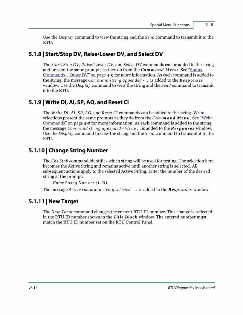
v6.14 RTU Diagnostics User Manual
Special Menu Functions 5 - 5
Use the Display command to view the string and the Send command to transmit it to the RTU.
5.1.8 | Start/Stop DV, Raise/Lower DV, and Select DV
The Start/Stop DV, Raise/Lower DV, and Select DV commands can be added to the string and present the same prompts as they do from the Command Menu. See “Status Commands – Other DV” on page 4-9 for more information. As each command is added to the string, the message Command string appended - … is added to the Responses window. Use the Display command to view the string and the Send command to transmit it to the RTU.
5.1.9 | Write DI, AI, SP, AO, and Reset CI
The Write DI, AI, SP, AO, and Reset CI commands can be added to the string. Write selections present the same prompts as they do from the Command Menu. See “Write Commands” on page 4-5 for more information. As each command is added to the string, the message Command string appended - Write … is added to the Responses window. Use the Display command to view the string and the Send command to transmit it to the RTU.
5.1.10 | Change String Number
The Chs Str# command identifies which string will be used for testing. The selection here becomes the Active String and remains active until another string is selected. All subsequent actions apply to the selected Active String. Enter the number of the desired string at the prompt:
Enter String Number (1-10):The message Active command string selected - … is added to the Responses window.
5.1.11 | New Target
The New Targt command changes the current RTU ID number. This change is reflected in the RTU ID number shown in the Title Block window. The entered number must match the RTU ID number set on the RTU Control Panel.

String5 - 6
HSQ Technology v6.14
5.1.12 | Load File
The Load File command loads a specified file that contains up to ten strings. Enter the file name of the string file at the prompt:
File name [strings]:The file must have the extension STR and be in the RTUDIAG directory. The message Reading string file [filename] successful is added to the Responses window. You can display the contents of the string by selecting the Display command (see “Display” on page 5-3).
5.1.13 | Save File
The Save File command saves all of the currently defined strings (up to ten) to a file. Enter the file name of the string file at the prompt:
File name [strings]:RTUDiag automatically adds the file extension STR and saves the file to the RTUDiag directory.
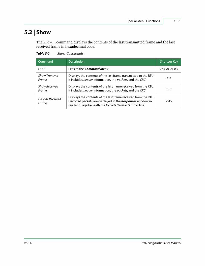
v6.14 RTU Diagnostics User Manual
Special Menu Functions 5 - 7
5.2 | Show
The Show… command displays the contents of the last transmitted frame and the last received frame in hexadecimal code.
Table 5-2. Show Commands
Command Description Shortcut Key
QUIT Exits to the Command Menu. <q> or <Esc>
Show Transmit
Frame
Displays the contents of the last frame transmitted to the RTU.
It includes header information, the packets, and the CRC.<t>
Show Received
Frame
Displays the contents of the last frame received from the RTU.
It includes header information, the packets, and the CRC.<r>
Decode Received
Frame
Displays the contents of the last frame received from the RTU.
Decoded packets are displayed in the Responses window in
real language beneath the Decode Received Frame: line.
<d>

Control Block Maintenance5 - 8
HSQ Technology v6.14
5.3 | Control Block Maintenance
Control Blocks are algorithms that carry out custom control strategies.
FYI: CBM is primarily used for editing individual Control Blocks, not creating or troubleshooting multiple Control Blocks.
Related Docs: For greater detail on Control Blocks, please refer to 25x86 Logic Processor User Manual, RTU Stand-Alone Tasks and 25x86 Logic Processor Control Blocks.
Figure 5-3. Control Block Maintenance Window
The CBM… command opens a new window that displays:
Control Block ID — this is the address of the current Control Block. A complete Control Block consists of the RTU ID and the CB address.
Control Block Contents — each line in this window shows the byte value, the byte number in hexadecimal, and a brief description. The description is in a text file with a DTA file extension in the RTUDiag directory, one per Control Block type.
CBM… Menu — with the following options:
Table 5-3. CBM Commands
Command Description Shortcut Key
QUIT Exits to the Command Menu. <q> or <Esc>
Clear Clears all Control Block bytes in the current window. <c>
Modify Modifies individual byte lines in a Control Block. <m>
CB ID Window
CB Contents
CBM Menu

v6.14 RTU Diagnostics User Manual
Special Menu Functions 5 - 9
By default, RTU Diagnostics does not display a Control Block until one is loaded. Once loaded into memory, the Control Block will remain there until replaced or the program is exited. Control blocks can be loaded from a file or from the RTU. After modification, they can be sent to the point of origin, to any other Control Block address in the RTU, or to a file.
Modified Control Blocks sent to the RTU perform according to the modification until the RTU is reset. At that point, all Control Blocks revert to the hard coded data (non-volatile storage) if the modifications were stored only in RAM.
Best Practices: Files for saving Control Blocks should be named for the site or the RTU address.
5.3.1 | Clear
The Clear command changes the value on each line of the Control Block to zero. There are no changes made to the RTU unless the Control Block is uploaded to the RTU memory (see “Save To RTU” on page 5-11).
R/T Upload Uploads a Control Block from the RTU in real time <r>
Load fr RTULoads a snapshot view of a Control Block from RAM or the
non-volatile storage of the RTU.<f>
Save to RTUSaves the displayed Control Block to the RAM or the non-
volatile storage of the RTU.<t>
Load fr File Loads a Control Block from a file. <l>
Save to File Saves the displayed Control Block to a named file. <s>
Point Involv Indicates which Control Blocks reference a point. <p>
CB Insert Inserts a Control Block between two existing Control Blocks. <i>
CB Delete Deletes a single Control Block from a file. <d>
File Update Selects the file update mode. <u>
File Compare Determines the differences between two Control Block files. <a>
PurgePurges all of the currently loaded Control Blocks from the RTU
RAM.<g>
Table 5-3. CBM Commands (continued)
Command Description Shortcut Key

Control Block Maintenance5 - 1 0
HSQ Technology v6.14
5.3.2 | Modify
The Modify command moves the cursor to the first byte line in the Control Block Contents window and displays a Modify dialog box:
The <Tab> key exits the Modify command without saving any changes and returns to the CBM… menu.
The <Esc> key saves the current Control Block entries and returns to the CBM… menu.
The <Enter> key places the new value in the highlighted line after typing it in at the prompt (new value:).
Arrow keys move the highlighted line to the next byte. If the cursor skips a line, that line cannot be modified.
Best Practices: Before entering modifications, it is a good idea to open the Help screen, <Alt-h>. Help is tailored to each line, displaying the symbolic constants appropriate for the byte highlighted.
The prompt (new value:), allows you to enter a new value for that Control Block. Other entries are determined by the byte being modified. Some byte lines accept expressions consisting of symbolic constants connected by operators.
The modified file must be saved in order for the modifications to become effective. See “Save To File” on page 5-12.
5.3.3 | Real Time Upload
The R/T Upload command uploads a Control Block from the RTU memory, in real time, so that you can see activity as it is happening. This is a display only option. At the prompt:
Enter Control Block address(1-256)[1]:Enter the Control Block Address to display. The address must be a number from 1 to 256. Press the <Esc> key to stop the display and return to the CBM… menu.
5.3.4 | Load From RTU
The Load fr RTU command loads a snapshot view of a Control Block from the RTU. At the prompt:
Upload Control from RAM or NON-VOLATILE STORAGE(R):Enter <r> to read from the Random Access Memory (RAM) or <s> to read from the non-volatile storage or Solid State Disk (SSD).
v6.14 RTU Diagnostics User Manual
Special Menu Functions 5 - 1 1
Best Practices: Over time the Control Blocks that are stored in RAM can become changed and the data modified. It is recommended that you load Control Blocks from the non-volatile storage instead.
At the prompt:Upload all control blocks and overwrite selected file [Y|N](N):
Entering [Y]es will display the prompt:Control Block File name [BCC1001.CBS]:
Enter a file name. If prompted, select whether to upload until the terminating block is read. If you select [N]o, enter the highest Control Block address to read up to. The next prompt is displayed:
Enter Control Block Address(1-256)[1]:Enter the Control Block address number.
5.3.5 | Save To RTU
The Save to RTU command saves the displayed Control Block directly to the RTU. The modifications will remain until the RTU is reset if the changes are only saved to RAM, otherwise the changes are permanent. The following prompt is displayed:
Download control blocks in active file [Y|N](N):If you enter [Y]es, type the name of the Control Block file at the prompt:
Control Block File name [BCC1001.CBS]:At the next prompt:
Download All/Terminating Block/Count(A):Determine whether to download [A]ll Control Blocks, download only [T]erminating Blocks, or download [C]ounts. If you select to download counts, enter the highest Control Block address to download from the file. At the next prompt:
Save Control Block to NON-VOLATILE STORAGE [Y|N](Y):If you enter [Y]es the Control Blocks are saved to the non-volatile memory or SSD. If you enter [N]o, you are prompted:
Store Control Blocks in active RAM [Y|N](Y):If you enter [Y]es, you are prompted:
Purge existing control blocks [Y|N](N):If you enter [Y]es the existing Control Blocks are purged (see “Purge” on page 5-14 for more details).
Next, select either Fast CB Downloads or Slow CB Downloads. If you are using a 286- or 386-based RTU, you must choose Slow CB Downloads. To stop the download at any time, press <Esc>.

Control Block Maintenance5 - 1 2
HSQ Technology v6.14
5.3.6 | Load From File
The Load fr File command loads a Control Block from a named file. Enter the file name at the prompt:
Control Block File name [BCC1001.CBS]:The file must have a CBS file extension. Enter the address at the prompt:
Enter Control Block Address(1-256)[1]:
5.3.7 | Save To File
The Save to File command saves the displayed Control Block to a file. The filename is created from the Control Block address with RTUDiag automatically adding a CBS file extension. The file is saved to the RTUDIAG directory. Enter a file name at the prompt:
Control Block File name [BCC1001.CBS]:Enter the address at the prompt:
Enter Control Block Address(1-256)[1]:
5.3.8 | Point Involvement
The Point Involv command searches the specified Control Block file to determine which Control Block(s) contain the selected point. To identify the Control Block number of select points, enter the point type at the prompt:
Point type (AO):You can select from AO, DI, AI, CI, DO, DVSS, DVRL, or SP. Enter a point to search for at the prompt:
Point to search for (<Alt-A> menu):To view the result, use the hotkey <Alt-r>. The Responses window displays the block number and byte number within the block where the point was found, along with each block and byte number that it finds.
5.3.9 | Control Block Insert
The CB Insert command inserts the currently displayed Control Block into a file containing multiple Control Blocks. RTUDiag inserts a Control Block(s) at the address specified and shifts the following Control Blocks down by one CB address. Enter the Control Block file name at the prompt:
Control Block File name [BCC1001.CBS]:The file extension must be CBS and stored in the same directory as RTUDiag. Enter the address at the prompt:
Enter Control Block Address(1-256)[1]:

v6.14 RTU Diagnostics User Manual
Special Menu Functions 5 - 1 3
5.3.10 | Control Block Delete
The CB Delete command deletes the named Control Block file. Enter the Control Block file name at the prompt:
Control Block File name [BCC1001.CBS]:Enter the address at the prompt:
Enter Control Block Address(1-256)[1]:The remaining Control Blocks are shifted up by one CB Address.
5.3.11 | File Update
The File Update command defines the file update mode. There are two operation modes, Update active file automatically and Explicit file saves only.
The Update active file automatically mode saves the active Control Block file when you exit the Modify screen and a change has been made to the displayed Control Block.
The Explicit file saves only mode specifies that the active Control Block is only saved by using the Save to File command.
The File Update mode is stored in the RTUDIAG.INI file and remains the same for future sessions.
5.3.12 | File Compare
The File Compare command compares two versions of the same control block file, byte by byte, and logs the differences in a file you specify. Enter the file name of the Control Block with the changes at the prompt:
Changes Block File name [BCC1001]:Enter the name of the file you are comparing it with (must be a different file name) at the prompt:
Reference Block File name [BCC1002]:Select to write any changes to a text file at the prompt:
Write found changes to text file [Y|N](N):Any differences between the two files is stored in the file named at the prompt:
Differences Text File Name [BCC1001]:The file is automatically given the DIF extension, which is readable by any third-party text editor. Any discrepancies are displayed in the Responses window. Use the hotkey <Alt-r> to view.

Control Block Maintenance5 - 1 4
HSQ Technology v6.14
5.3.13 | Purge
The Purge command purges (erases) all of the currently loaded Control Blocks from the RTU RAM. To confirm this course of action enter [Y]es at the prompt:
Confirm control block erasure in RTU [Y|N](N):The Sending Command… message is displayed and the RTU is purged. If you enter [N]o, the Purge command terminates without results.
6 - 1v6.14 RTU Diagnostics User Manual
S E C T I O N 6
RTU MENU COMMANDS
The RTU… commands govern the way the RTU acts and responds. This section details how to define board and RTU configurations and includes descriptions for the following:
Common RTU Commands
RTU Hardware Configuration
Model 2500 RTU Specific Commands
FYI: Throughout this section, most of the commands, functions, and menus apply to the HSQ Model 25x86 and 6000 RTUs. However, some commands are specific to individual models. Information for the HSQ Model 2500 and HSQ Model 2500/86 RTUs is included here for legacy users.

Common RTU Commands6 - 2
HSQ Technology v6.14
6.1 | Common RTU Commands
Some commands are used by all HSQ RTUs, while some are specific to various models of RTUs. Some of the following RTU commands open a dialog box with a menu of options; others simply execute a specific function. Commands specific to the Model 2500 RTU can be found at the end of this section in “Model 2500 RTU Specific Commands” on page 6-29.
Figure 6-1. RTU Command
While a command is being processed, the message Sending command… is displayed and verification of the action is shown in the Responses window. The command is then added to the Previous Commands window.
Figure 6-2. RTU Menu
When the RTU… command is selected, a secondary menu is displayed. The options are:
Table 6-1. RTU Menu Commands
Command Description Shortcut Key
QUIT Exits to the Command Menu. <q> or <Esc>
Read All RTU Reads all points defined in the RTU for their COS status. <d>
Initialize RTU Sends an Initialize command to the RTU. <z>
Reboot RTU Restarts the RTU. <b>
Get statusDisplays the current status and software version of the
RTU (not applicable for the 2500).<s>

v6.14 RTU Diagnostics User Manual
RTU Menu Commands 6 - 3
6.1.1 | Read All RTU
The Read All RTU command generates a COS report for all the points defined in the RTU. If you are in NoCOS ID mode, all COS data is sent to the Host and the message NON HOST ID FOR TESTSET is shown. The message Read all points defined in RTU is displayed in the Responses window.
6.1.2 | Initialize RTU
The Initialize RTU command forces the RTU to erase all point definitions and initiate a download from the MISER Host (if it is online).When you select this command you are prompted to confirm the initialization process. This feature is not commonly used.
Figure 6-3. Initialization Confirmation Prompt
Force RTU Rpt Forces the RTU COS report. N/A
Disable RTU Disables RTU COS transmission. <l>
Enable RTU Enables RTU COS transmission. <e>
Force stnd alone Forces the RTU to operate in Stand-Alone mode. <a>
Unfrc stnd alone Returns the RTU to normal mode. N/A
Set Throttle Limits the size of the frames carrying COS transmissions. <h>
RTU Hardwr Cnfg… See “RTU Hardware Configuration” on page 6-8. <w>
Read Directory Displays the files stored on the RTU. <o>
Read Diagnostics Generates a report detailing the internal RTU diagnostics. <r>
Get File Sends a file to the RTU. <g>
Put File Retrieves a file from the RTU. <p>
Set RTU time Sets the date and time in the RTU. <t>
Delete File Deletes a file from the RTU. N/A
Table 6-1. RTU Menu Commands (continued)
Command Description Shortcut Key
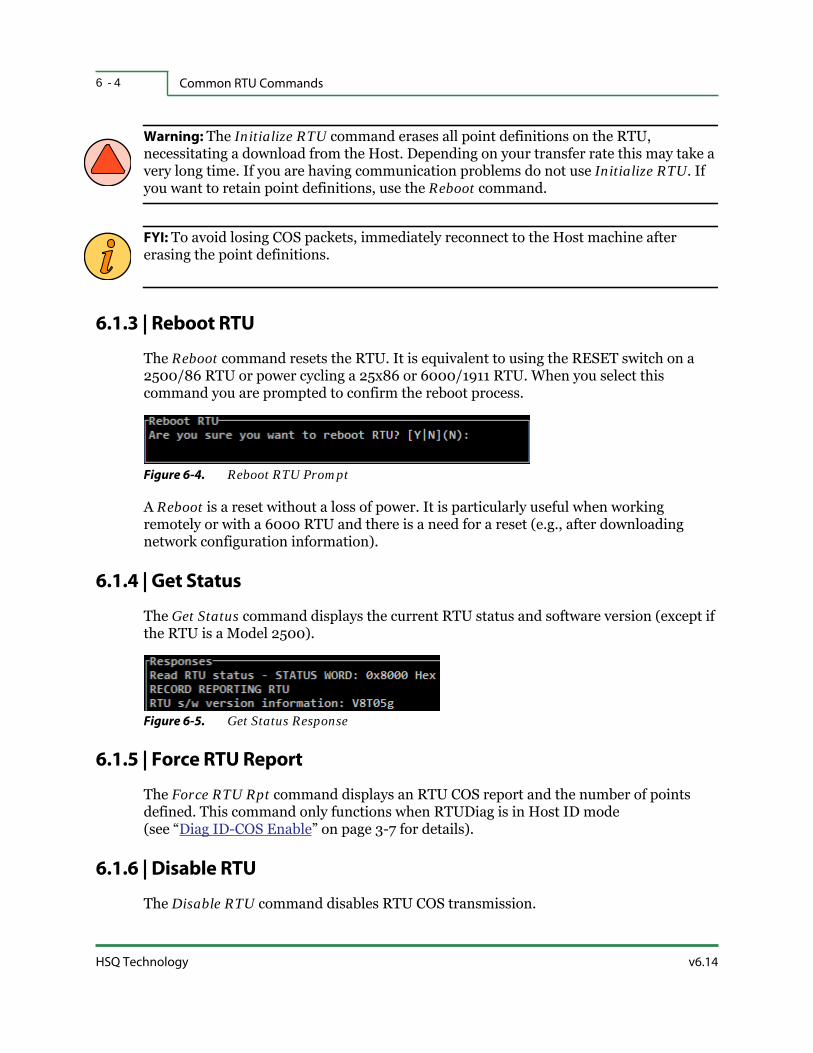
Common RTU Commands6 - 4
HSQ Technology v6.14
Warning: The Initialize RTU command erases all point definitions on the RTU, necessitating a download from the Host. Depending on your transfer rate this may take a very long time. If you are having communication problems do not use Initialize RTU. If you want to retain point definitions, use the Reboot command.
FYI: To avoid losing COS packets, immediately reconnect to the Host machine after erasing the point definitions.
6.1.3 | Reboot RTU
The Reboot command resets the RTU. It is equivalent to using the RESET switch on a 2500/86 RTU or power cycling a 25x86 or 6000/1911 RTU. When you select this command you are prompted to confirm the reboot process.
Figure 6-4. Reboot RTU Prompt
A Reboot is a reset without a loss of power. It is particularly useful when working remotely or with a 6000 RTU and there is a need for a reset (e.g., after downloading network configuration information).
6.1.4 | Get Status
The Get Status command displays the current RTU status and software version (except if the RTU is a Model 2500).
Figure 6-5. Get Status Response
6.1.5 | Force RTU Report
The Force RTU Rpt command displays an RTU COS report and the number of points defined. This command only functions when RTUDiag is in Host ID mode (see “Diag ID-COS Enable” on page 3-7 for details).
6.1.6 | Disable RTU
The Disable RTU command disables RTU COS transmission.

v6.14 RTU Diagnostics User Manual
RTU Menu Commands 6 - 5
6.1.7 | Enable RTU
The Enable RTU command enables RTU COS transmission.
6.1.8 | Force Stand Alone
The Force stnd alone command sets the RTU to operate in Stand-Alone mode, meaning the RTU does not send COS to the Host. If “background” Control Blocks are programmed, the RTU executes the “background” algorithms in addition to the “foreground” Control Blocks.
Related Docs: For more information on background and foreground Control Block algorithms, refer to 25x86 Logic Processor User Manual, RTU Stand-Alone Tasks.
6.1.9 | Unforce Stand Alone
The Unfrc stnd alone command returns the RTU to normal controls.
6.1.10 | Set Throttle
The Set Throttle command determines the size limit of frames that contain the COS report. Each time a COS report is generated, it is queued for transmission to the Host. When the RTU is allowed to send the COS information, it is sent to the Host combined with as many other reports as possible in a separate frame.
When you select the Set Throttle command the following prompt for 16-bit protocol is displayed:
New throttle rate (min-10 max-512):For 8-bit protocol, the minimum is six and the maximum is 255.
6.1.11 | Read Directory
The Read Directory command prompts you for a file name. By default, the file name will be *.*. If left blank, you will get a list of all the existing files on the RTU. To retrieve a specific file, enter the file name and extension or use wildcards (e.g., *.RTU).
6.1.12 | Read Diagnostics
The Read Diagnostics command generates a report in the Responses window that shows details of the internal RTU diagnostics (e.g., the RTU MAC address, current RTU time, the CPU BIOS version, transmission and CRC errors, etc.).

Common RTU Commands6 - 6
HSQ Technology v6.14
6.1.13 | Get File
The Get File command retrieves a file from the RTU and places it in the local directory (e.g., C:\RTU\RTUDIAG).
6.1.14 | Put File
The Put File command sends a file to the RTU, reading it from the local directory(e.g., C:\RTU\RTUDIAG).
Warning: The Get File and Put File commands are advanced features and should only be used by experienced technicians.
6.1.15 | Set RTU Time
The Set RTU time command displays the current time (day of the week, date-month-year, hour:minute:second, and season) and allows you to reset it if required for testing. If the Host is in communication with the RTU when it sends the current time, any changes made here will be overridden. Selecting this command displays the current time followed by the prompt:
Enter time [15:4:58]:Enter the desired time in 24-hour format. The next prompt is:
Holiday bit map (bits 0-15 = today-15 days in future [0]:The next prompt is:
Enter date [12-APR-118]:Enter the date using the three letter abbreviation for the month (e.g., 12-APR-2018). The next prompt is:
Enter day-of-week [THU]:Enter the day of the week using the three letter abbreviation (e.g., THU). The next prompt is:
Enter season [S]:Enter the season letter. Choose between Summer (S) or Winter (W).
FYI: This command is only useful for a 2504 type RTU that is powered on without communicating with a Host computer.

v6.14 RTU Diagnostics User Manual
RTU Menu Commands 6 - 7
Warning: It can have undesired effects if you set the time on an RTU that is communicating with the Host computer. This will cause data reported to the Host to have an incorrect timestamp.
6.1.16 | Delete File
The Delete File command permanently deletes a file from the RTU. Enter the full name of the file to be deleted, including the extension (e.g., POINTMAP.BRD).
Enter the delete file name:
Warning: This command will permanently delete the named file from the RTU memory. Since this has the potential to adversely effect the operation of the RTU, it should only be used by experienced technicians.

RTU Hardware Configuration6 - 8
HSQ Technology v6.14
6.2 | RTU Hardware Configuration
Figure 6-6. RTU Hardware Configuration Command
While a command is being processed, the message Sending command… is displayed and verification of the action is shown in the Responses window. The command is then added to the Previous Commands window.
Figure 6-7. RTU Hardware Configuration Menu
When the RTU Hrdwr Cnfg… command is selected, a third-level menu is displayed. The options are:
Table 6-2. RTU Hardware Configuration Commands
Command Description Shortcut Key
QUIT Exits to the RTU menu. <q> or <Esc>
Point Map… Sets the point addresses, board types, etc. <m>
Send Config Loads the configuration file into the RTU. <d>
Read Config Displays the current RTU configuration. <f>
COM ports 3 & 4…Sends and reads configuration information about COM
ports 3 and 4.<p>
Network…Sends and reads configuration information about the
network connection.<n>
Modem…Sends and reads configuration information about a dialup
modem.<o>
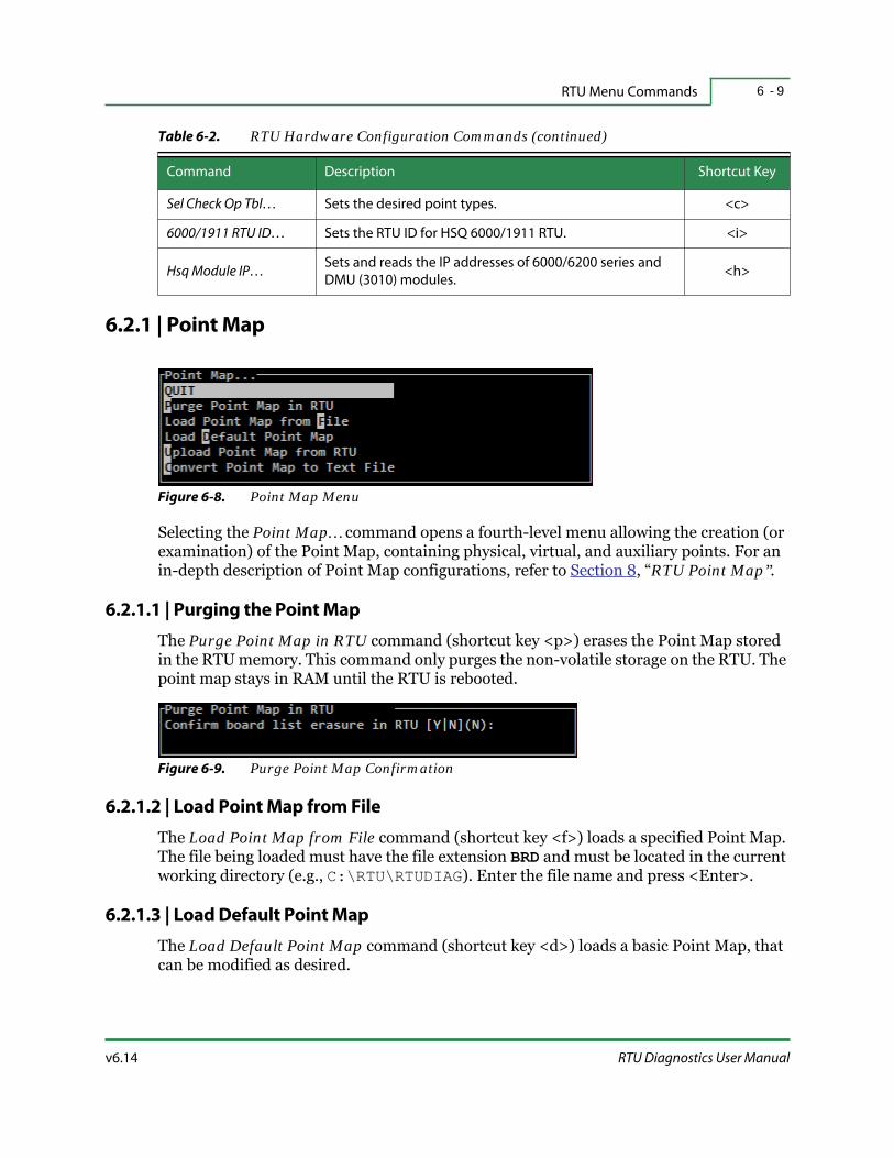
v6.14 RTU Diagnostics User Manual
RTU Menu Commands 6 - 9
6.2.1 | Point Map
Figure 6-8. Point Map Menu
Selecting the Point Map… command opens a fourth-level menu allowing the creation (or examination) of the Point Map, containing physical, virtual, and auxiliary points. For an in-depth description of Point Map configurations, refer to Section 8, “RTU Point Map”.
6.2.1.1 | Purging the Point Map
The Purge Point Map in RTU command (shortcut key <p>) erases the Point Map stored in the RTU memory. This command only purges the non-volatile storage on the RTU. The point map stays in RAM until the RTU is rebooted.
Figure 6-9. Purge Point Map Confirmation
6.2.1.2 | Load Point Map from File
The Load Point Map from File command (shortcut key <f>) loads a specified Point Map. The file being loaded must have the file extension BRD and must be located in the current working directory (e.g., C:\RTU\RTUDIAG). Enter the file name and press <Enter>.
6.2.1.3 | Load Default Point Map
The Load Default Point Map command (shortcut key <d>) loads a basic Point Map, that can be modified as desired.
Sel Check Op Tbl… Sets the desired point types. <c>
6000/1911 RTU ID… Sets the RTU ID for HSQ 6000/1911 RTU. <i>
Hsq Module IP…Sets and reads the IP addresses of 6000/6200 series and
DMU (3010) modules.<h>
Table 6-2. RTU Hardware Configuration Commands (continued)
Command Description Shortcut Key

HSQ Technology v6.14
RTU Hardware Configuration6 - 1 0
Figure 6-10. Load Default Point Map View
Press the <Insert> key to add new points.
Press the <Delete> key to remove points.
Press the <Enter> key to edit a point.
Press the <Esc> key to exit the Point Map display.
When you are finished, you are given several options for exiting this screen:
Save to file and continue — Saves the Point Map to a file and allows you to continue editing. You will be prompted to enter a file name.
Download to RTU — Downloads the Point Map currently on the screen to the RTU. Any Point Map currently stored in the RTU memory will be purged first.
Exit and lose unsaved changes — Closes the Point Map screen without saving any new information.
Cancel — Closes this window and returns to the Point Map screen.
6.2.1.4 | Upload Point Map from RTU
The Upload Point Map from RTU command (shortcut key <u>) reads the Point Map stored in the RTU memory and displays it.
Best Practices: It is recommended that you use this command after you have downloaded a Point Map to the RTU to verify that the process has occurred without error.
6.2.1.5 | Convert Point Map to Text File
The Convert Point Map to Text File command (shortcut key <c>) creates an ASCII text file of the points database that can be read by any text editor. Supply a file name when prompted and press <Enter>. RTUDiag automatically adds the TXT file extension and saves the file in the working directory.
6.2.2 | Send Configuration
The Send Config command sends a configuration file to the RTU. You are prompted for a file name but it is not necessary to add the file extension. This file will become the default the next time you use the Send Config command.
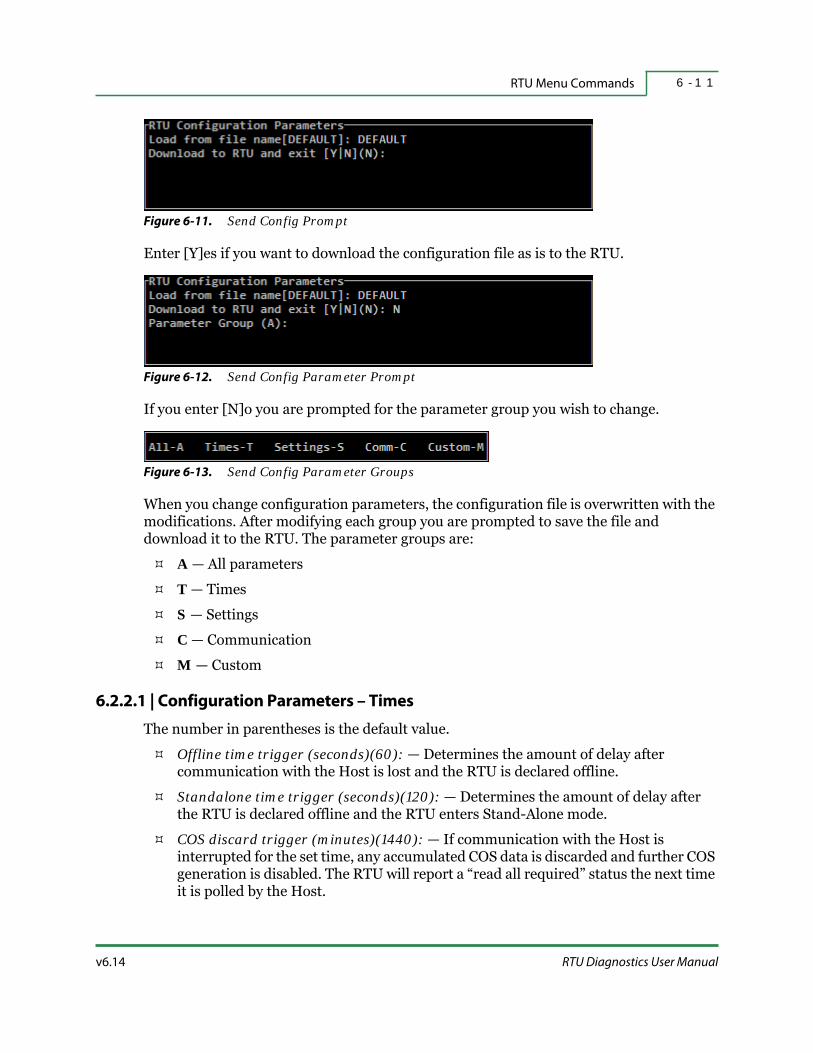
v6.14 RTU Diagnostics User Manual
RTU Menu Commands 6 - 1 1
Figure 6-11. Send Config Prompt
Enter [Y]es if you want to download the configuration file as is to the RTU.
Figure 6-12. Send Config Parameter Prompt
If you enter [N]o you are prompted for the parameter group you wish to change.
Figure 6-13. Send Config Parameter Groups
When you change configuration parameters, the configuration file is overwritten with the modifications. After modifying each group you are prompted to save the file and download it to the RTU. The parameter groups are:
A — All parameters
T — Times
S — Settings
C — Communication
M — Custom
6.2.2.1 | Configuration Parameters – Times
The number in parentheses is the default value.
Offline time trigger (seconds)(60): — Determines the amount of delay after communication with the Host is lost and the RTU is declared offline.
Standalone time trigger (seconds)(120): — Determines the amount of delay after the RTU is declared offline and the RTU enters Stand-Alone mode.
COS discard trigger (minutes)(1440): — If communication with the Host is interrupted for the set time, any accumulated COS data is discarded and further COS generation is disabled. The RTU will report a “read all required” status the next time it is polled by the Host.
RTU Hardware Configuration6 - 1 2
HSQ Technology v6.14
CI Scan Rate (millisecs)(100): — Controls the rate at which Counter Input processes are executed.
DI Scan Rate (millisecs)(100): — Controls the rate at which Digital Input processes are executed.
Control Block Scan Rate (millisecs)(1000): — Controls the rate at which Control Block processes are executed.
First Control Block Scan Delay (millisecs)(100): — Controls the delay after a reset/reboot (or power up) before any control blocks are processed.
Comm Delay after host reset (secs)(20): — This is currently not in use.
COS by record number[Y|N](Y): — Used to enable COS reporting by record number (rather than point number).
FYI: 2500, 2500/86, and 25x86 RTUs: The ONLINE TO HOST LED (on the front of the RTU) is lit whenever the RTU receives a communications frame from the Host. This resets the offline timer. When the offline timer expires, the ONLINE TO HOST LED flashes. When the stand-alone timer expires, the ONLINE TO HOST LED switches off and the STAND ALONE ACTIVE LED illuminates.
6.2.2.2 | Configuration Parameters – Settings
The number in parentheses is the default value.
COS Time Stamp(None-H/M/S/Milli)[N:S:M:H:MSEC](MSEC): — Sets the resolution of the time stamp reported on all COS reports generated by the RTU.
AI COS Tolerance (counts)(1): — Represents the minimum difference between AI readings before AI COS values are processed.
FYI: Each AI point definition includes a tolerance, but any point definition tolerance less than the global AI COS Tolerance value, will be effectively changed to the global value.
COS Overflow(Discard:All/Old/New)[A|O|N](A): — selects the strategy to use, if and when the internal COS buffering region(s) are filled. The choices are:
A — Discard all COS and disable further collection.
O — Retain the existing COS data but discard any further collection.
N — Discard the oldest COS data in favor of new COS data.In all three cases, the RTU will report a “read all required” indication to the Host to indicate the loss of data.
Control Block Season Offset (blocks)(0): — Number of control blocks that are used in the Summer only. If any number except zero is selected, the tests of control blocks (out of a maximum of 255) will only be used in the Winter.

v6.14 RTU Diagnostics User Manual
RTU Menu Commands 6 - 1 3
Select/Check/Operate [Y|N](N): — [Y] enables select/operate mode for all output points in the RTU. If [N] is selected, all select commands are rejected by the RTU.
Select/Check/Operate Timeout (seconds)(10): — When enabled, this value specifies the maximum interval between the select command and the following operate command. If a longer period has elapsed, the operate command is rejected by the RTU.
Save pnts defs in non-volatile mem[Y|N](Y): — [Y]es means that point definitions (Host or RTU Diagnostics) are saved in the non-volatile memory. If [N]o is selected, point definitions are only saved in RAM.
6.2.2.3 | Configuration Parameters – Communications
The number in parentheses is the default value.
Max Frame Size - 8-bit [6-255](128): — This value selects the maximum frame length.
Max Frame Size - 16-bit [10-65535](128): — This value selects the maximum frame length.
FYI: These values affect all frames transmitted by the RTU for the two different HSQ protocols (8-bit and 16-bit). Frame length can be further affected by the throttle value used to limit the amount of COS data sent in a frame.
The values below are used to configure the first RS-232 communication port on the RTU.
Figure 6-14. Protocol Parameter Helper
When selecting Protocol Port 1, a Parameter Helper displays the protocol options.
Protocol Port 1 [8|16](8): — Assigns the communication protocol to use. Select the appropriate protocol from the Parameter Helper box.
FYI: For information on the HSQ16E protocol and encrypting communications between the Host and the RTU, refer to “Encrypted Communication” on page 6-14.
Port 1 Baud Rate(9600): — Assigns the port speed for COM port 1. A Parameter Helper box at the top of the screen displays the available rates.
Port 1 Front Porch(millisecs)(60): — See “Front Porch” on page 3-7.
Port 1 Back Porch(millisecs)(20): — See “Back Porch” on page 3-10.

RTU Hardware Configuration6 - 1 4
HSQ Technology v6.14
Port 1 Transmission timeout(millisecs)(100): — This sets the time for the communication port to reply before the RTU stops transmitting anything on that port.
Port 1 Frame timeout(millisecs)(30): — Represents the maximum amount of time that can occur between successive characters before a frame timeout is declared. This value may require a longer setting than the default of 30 ms. If intelligent modems are involved in the communication path, factors like error-correction or modem internal buffering may effect the timeout.
Port 1 Reply Delay(millisecs)(20): — Forces a delay between the reception of a frame and the transmission of a reply. The RTU waits the specified time before turning on RTS. This time delay precedes the Front Porch value.
Port 1 Silence(bytes)(5): — This value is used to determine the number of retries for Modbus and ASI type MUX devices.
Best Practices: Some delay should be programmed between frames in order to allow time for the RTU to process the incoming frame. Typically, a Reply Delay of ten to twenty milliseconds is sufficient.
Protocol Port 2 is identical to Port 1, but refers to the second RS-232 COM port on the RTU.
6.2.2.4 | Configuration Parameters – Custom
Custom_Param_1 through Custom_Param_9 represent customer parameter configuration values used by some RTU firmware. These are typically site-specific, if a site does not have custom parameters these values should remain unchanged. They should be set and correspond to the Custom Prompts (as described in “Custom Prompts” on page 3-12). Custom_Param_7, Custom_Param_8, and Custom_Param_10 are special cases, refer to “Custom Parameter 7”, “Custom Parameter 8”, and “Custom Parameter 10” on page C-3 for details.
6.2.2.5 | Encrypted Communication
Starting with RTUDiag version 6.12 and RTU Software version R12g, it is possible to encrypt communications between the Host and the RTU. This increases the Security Level of the installation.
To enable encryption, enter HSQ16E in the Protocol Port (either 1 or 2) field. This only encrypts communications between the Host and the RTU, it does not encrypt communications between the RTU and the PC running RTUDiag.
Warning: Do not encrypt the port the PC running RTUDiag is connected to as it will no longer be available to use.

v6.14 RTU Diagnostics User Manual
RTU Menu Commands 6 - 1 5
6.2.3 | Read Configuration
The Read Config command displays the current RTU configuration parameters.
RTUDiag prompts you to enter a filename for an optional Save File (the CFG file extension is added automatically). The saved file can be modified later and downloaded to the RTU with the Send Config command. Pressing <Enter> or <Esc> exits without saving the uploaded information. However, the information is still displayed in the Responses window.
FYI: Not all RTUs provide the same results. Your particular system will determine the returns you receive when using this command. Below is a list of all possible results and an explanation.
These typical values are the same as those described in “Send Configuration” on page 6-10.
Offline time trigger (seconds): 60Standalone time trigger (seconds): 120COS discard trigger (minutes): 1440CI Scan Rate (millisecs): 100DI Scan Rate (millisecs): 100Control Block Scan Rate (millisecs): 1000First Control Block Scan Delay (millisecs): 100Comm Delay after host reset (secs): 20COS by record number[Y|N]: YCOS Time Stamp(None-H/M/S/Milli)[N|S|M|H|MSEC]: MSECAI COS Tolerance (counts): 1COS Overflow (Discard:All/Old/New)[A|O|N]: AControl Block Season Offset (blocks): 0Select/Check/Operate [Y|N]: NSelect/Check/Operate Timeout (seconds): 10Save pnts defs in non-volatile mem[Y|N]: YMax Frame Size - 8-bit [6-255]: 128Max Frame Size - 16-bit [10-65535]: 128Protocol Port 1 [8|16]: 8Port 1 Baud Rate: 9600Port 1 Front Porch(millisecs): 60Port 1 Back Porch(millisecs): 20Port 1 Transmission timeout(millisecs): 100Port 1 Frame timeout(millisecs): 30Port 1 Reply Delay(millisecs): 20Port 1 Silence(bytes): 5Protocol Port 2 [8|16]: 8Port 2 Baud Rate: 9600Port 2 Front Porch(millisecs): 60Port 2 Back Porch(millisecs): 20Port 2 Transmission timeout(millisecs): 100Port 2 Frame timeout(millisecs): 30

RTU Hardware Configuration6 - 1 6
HSQ Technology v6.14
Port 2 Reply Delay(millisecs): 20Port 2 Silence(bytes): 5Custom_Param_1: 0Custom_Param_2: 0Custom_Param_3: 0Custom_Param_4: 0Custom_Param_5: 0Custom_Param_6: 0Custom_Param_7: 0Custom_Param_8: 0Custom_Param_9: 0Custom_Param_10: 0
The following values are display values only, they are not configurable. They show the physical address and size of the two possible non-volatile memory devices.
RTU NON-VOLATILE STORAGE 1 Address: 0X0RTU NON-VOLATILE STORAGE 1 Size: 0X0RTU NON-VOLATILE STORAGE 2 Address: 0X0RTU NON-VOLATILE STORAGE 2 Size: 0X0
Serial port parameters:
SERIAL PORT 1: Frame Reception 0Frame Completions 0Frame Transmissions 0Missed Transmissions 0Missed Receptions 0CRC Errors 0UART Errors 0Packet Length Errors 0IDs Received 0Serial Ports Reset 0
SERIAL PORT 2: Frame Reception 2Frame Completions 2Frame Transmissions 1Missed Transmissions 0Missed Receptions 0CRC Errors 0UART Errors 0Packet Length Errors 0IDs Received 0Serial Ports Reset 0
Explanation for Serial Communication Ports 1 and 2:
Frame Receptions — Total number of good frames received by the RTU.
Frame Compilations — Total number of frames received by the RTU with the same destination ID (frame header) as the RTU address.
Frame Transmissions — The number of frames sent to the Host (this may not include responses to polls).

v6.14 RTU Diagnostics User Manual
RTU Menu Commands 6 - 1 7
Missed Transmissions — Number of retransmit requests from the Host, that the RTU cannot find the proper sequence number for. This may be an indication of the number of commands that the RTU missed.
Missed Receptions — Number of retransmit requests that the RTU can correlate with the proper sequence number. This indicates that the RTU sent the request but the Host may not have received it.
CRC Errors — Frames received by the RTU that failed the CRC error check.
UART Errors — Counts the number of UART errors detected by the RTU overruns, framing, parity, and line break.
Packet Length Error — Number of inter-character timeout errors that the RTU had.
IDs Received — Not currently implemented.
Serial Ports Reset — Not currently implemented.
EEPROM Data Parameters:
EEPROM DATA: Page Retries 2563In Write loop NoWrite fail NoMemory Available 32120Free Blocks 1DI Blocks 0AI Blocks 0CI Blocks 0DV Blocks 0AO Blocks 0SP Blocks 0Board Blocks 5Board Parameters Blocks 0Control Blocks Count 0High EEPROM MissingEEPROM OkayEEPROM Test SuccessfulSelf Clears 198Last Clear ReasonHeap Clear POWER_RESETLast Heap Init ReasonResets 0Last Reset ReasonWatchdog Resets 204Manual Resets 192Host Resets 196Power Resets 0
Explanation for EEPROM Data:
EEPROM Retries — Updates the count of fails of final byte written reads, in the time specified (kept in EEPROM).

RTU Hardware Configuration6 - 1 8
HSQ Technology v6.14
In-Write Loop — Software currently in loop to commit page to EEPROM.
EEPROM Write Fail — Check at end of startup that EEPROM writes have completed.
Free Blocks — Blocks of free space, beginning with 1 if one EEPROM is installed, 2 if two EEPROMs are installed.
DI Blocks — Number of digital input points defined.
AI Blocks — Number of analog input points defined.
CI Blocks — Number of counter input points defined.
DV Blocks — Number of digital output points defined.
AO Blocks — Unused.
SP Blocks — Number of setpoints defined.
Board Blocks — Number of boards in point map.
Board Parameters — Number of board parameter blocks defined (possibly shared between boards).
Control Blocks — Number of control blocks in EEPROM.
Missing EEPROMS — Sets on startup if the software does not see an EEPROM.
Bad EEPROM — Sets when writing and retries exceed limit (20).
EEPROM Test Result — Initializes to test, not run. Shows status of the last test (underway, aborted, successful, failed, or no temporary memory).
Self Clear — Increments when EEPROM initializes. Can be commanded to clear. Software will clear if it detects a bad list pointer.
Last Clear Reason — Displays the reason for last EEPROM clear.
Heap Clear — Area of RAM, increments when heap is cleared.
Heap Clear Reason — Displays reason for the last heap clear.
Point Space Configuration Parameters:
POINT SPACE CONFIGURATION: Invalid EEPROM Board Configurations 0Point Overlay Setup Aborts (bitfield = type #) 0Memory Allocation Failure (bitfield = type #) 0COS Buffer Writes 2COS Packets Created 0COS Buffer Purges 0Assigned Memory 457856Allocated Memory 443680Exit Code 22Unserviced Interrupts PIC#1 0Unserviced Interrupts PIC#2 0

v6.14 RTU Diagnostics User Manual
RTU Menu Commands 6 - 1 9
Buffers Allocd: Rcv #1-1 #2-1 Trans: #1-1 #2-1Buffers Allocd: Rcv #1-1 #2-2 Cmd Resp:#1-1 #2-1 COS: 0Custom Initialization Aborted No
Explanation for Point Space Configuration Parameters:
Invalid EEPROM Board Configurations — On Point Map configuration, tests for point type compatibility with board type.
Point Overlap Setup Aborts — When initializing, sets up the point space per the Point Map. Checks for overlaps, reports bit map to show the problem point type (bit 0 = AO, bit 1 = DI, bit 2 = AI, bit 3 = CI, bit 4 = DV, bit 6 = SP).
Memory Allocation Failures — Failures during setup of the point space, reports bit 0x8000 set if board table memory problem or point type bit map, otherwise see above.
COS Buffer Writes — Increments when packet is put into COS buffer.
COS Packets Created — Increments when packet is put into transmit buffer.
COS Buffer Purges — Increments when it is necessary to purge COS buffer.
Assigned Memory — Amount of RAM available (AMX memory manager).
Allocated Memory — Memory used for board space, point space, etc.
Exit Code — Not used.
Unserviced Interrupts — Increments if a short interrupt occurs. Counts to indicate potential problems in interrupt lines.
Buffers Allocated — Tracks buffer allocation by type.
Custom Initialization Aborted — Used for RTU custom applications.
6.2.4 | COM Ports 3 and 4
The COM ports 3 & 4… command reads and sends the configuration information in the same way as is done for ports 1 and 2. Refer to “Send Configuration” on page 6-10 for details.
6.2.5 | Network
The Network… command is used to read and configure the network parameters (IP address, subnet mask, etc.) for the RTU and any connected Remote I/O modules.

RTU Hardware Configuration6 - 2 0
HSQ Technology v6.14
Figure 6-15. Network Configuration
When configuring RTU IP Addresses, the values are expressed in “dot-decimal notation” consisting of four numbers ranging from zero to 255, separated by dots. RTU IP Address is based on three factors:
Base IP Address — Your Network Administrator chooses this value.
RTU ID Switch — This value is set by a rotary switch on the RTU (except for 6000 RTUs). Refer to “RTU System Information” on page 1-6 for information.
RTU ID Coefficient — You choose this value.
These values are used in the following formula to generate the last decimal digit of the actual RTU IP address.
Last digit of the RTU IP address = last two digits of the Base IP address + (RTU Switch ID Number × RTU ID Coefficient).
For example, if the following values are used:
Base IP Address — 10.5.71.45
RTU ID Switch — 74
RTU ID Coefficient — 0
Then the last number of the RTU IP address is 45 + (74 * 0) = 45.
This allows for several different scenarios:
If the RTU ID Coefficient is zero (default), the last number is the Base IP Address. This is most commonly used and works for most instances.
If the last number of the Base IP Address is zero and the RTU ID Coefficient is one, the last number defaults to that of the RTU Rotary ID Switch setting.
Other possible combinations of the three parameters allow you to set successive last numbers for the RTU IP address.
6.2.5.1 | Read RTU Configuration Parameters
Figure 6-16. Read RTU Configuration Parameters

v6.14 RTU Diagnostics User Manual
RTU Menu Commands 6 - 2 1
You are prompted to select which RTU LAN configuration you wish to read (regardless of the actual number of LAN ports). If your RTU only has one LAN port, LAN1 must be used. The Read RTU LANx config command displays the current network configuration in the Responses window. You can also save the configuration information if you want; enter a name for the file and press <Enter>. Refer to Table 1-1 on page 1-4 for file extension information.
6.2.5.2 | Send RTU Configuration Parameters
The Send RTU config command is used to set the initial network parameters or to modify existing settings. The values below are used to configure the Ethernet port(s) on the RTU.
Figure 6-17. Send Network Parameters
If your RTU has more than one Ethernet port, you are prompted to select the appropriate RTU LAN configuration. To edit the configuration, type <Y> and press <Enter>.
Warning: Do not change either the RTU ID Coefficient, the Base IP Address, the Subnet Mask, or the Default Gateway Address without first consulting with your Network Administrator.
Figure 6-18. Protocol Parameter Helper
The Network configuration parameters are:
NETWORK protocol [8|16](16): — Assign the network protocol to use with the RTU. Select the appropriate protocol from the Parameter Helper box.
RTU ID Coefficient:(0) — Used to tie (or not tie) the IP address to a specific RTU ID. It can also be used to automatically determine IP addresses of additional network devices.
Base IP Address[3]:, Base IP Address[2]:, Base IP Address[1]:, Base IP Address[0]: — Numbers must be entered in order with the leftmost number assigned to Base IP Address[3] and the rightmost number assigned to Base IP Address[0]. Continue by entering all four numbers.
Subnet Mask[3]:, Subnet Mask[2]:, Subnet Mask[1]:, Subnet Mask[0]:— Used to determine network data routing. This network parameter is also represented in dot-decimal notation.
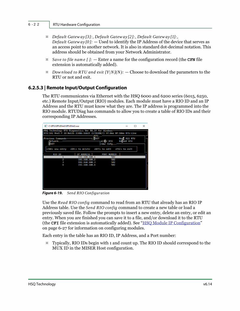
RTU Hardware Configuration6 - 2 2
HSQ Technology v6.14
Default Gateway[3]:, Default Gateway[2]:, Default Gateway[1]:, Default Gateway[0]: — Used to identify the IP Address of the device that serves as an access point to another network. It is also in standard dot-decimal notation. This address should be obtained from your Network Administrator.
Save to file name [ ]: — Enter a name for the configuration record (the CFN file extension is automatically added).
Download to RTU and exit [Y|N](N): — Choose to download the parameters to the RTU or not and exit.
6.2.5.3 | Remote Input/Output Configuration
The RTU communicates via Ethernet with the HSQ 6000 and 6200 series (6015, 6250, etc.) Remote Input/Output (RIO) modules. Each module must have a RIO ID and an IP Address and the RTU must know what they are. The IP address is programmed into the RIO module. RTUDiag has commands to allow you to create a table of RIO IDs and their corresponding IP Addresses.
Figure 6-19. Send RIO Configuration
Use the Read RIO config command to read from an RTU that already has an RIO IP Address table. Use the Send RIO config command to create a new table or load a previously saved file. Follow the prompts to insert a new entry, delete an entry, or edit an entry. When you are finished you can save it to a file, and/or download it to the RTU (the CFI file extension is automatically added). See “HSQ Module IP Configuration” on page 6-27 for information on configuring modules.
Each entry in the table has an RIO ID, IP Address, and a Port number:
Typically, RIO IDs begin with 1 and count up. The RIO ID should correspond to the MUX ID in the MISER Host configuration.

v6.14 RTU Diagnostics User Manual
RTU Menu Commands 6 - 2 3
The IP Address must match the address programmed into the RIO module. The HSQ default IP Address for an RIO module is 192.168.100.x (where x is the last two digits of the module model number). For example, the default IP address for an HSQ-6018 module would be: 192.168.100.18.
The standard Port number is 502.
FYI: After downloading the network configuration information, the RTU must be rebooted in order for the changes to take effect. Refer to “Reboot RTU” on page 6-4 for more information.
6.2.6 | Modem
Select the Modem… command to configure the dialup parameters.
Figure 6-20. Modem Configuration Menu
6.2.6.1 | Read Configuration
The Read config command displays the current modem configuration parameters stored in the RTU memory.
6.2.6.2 | Send Configuration
The Send config command is used to set the initial modem parameters or to modify the existing ones. At the Load from file name[]: prompt, you can choose to load a file for editing or create a new one.
FYI: When modifying parameters that require a time interval, the interval unit (seconds) is displayed in the upper left corner of the RTU Diagnostics Main Menu window.

HSQ Technology v6.14
RTU Hardware Configuration6 - 2 4
Figure 6-21. Modem Parameters
Eight modem parameters can be set using RTUDiag. They are:
Table 6-3. Modem Configuration Parameters
Parameter Description
MODEM COM PORT: The serial port number for the modem. The default is 2.
MODEM
INITIALIZATION STRING:
A sequence of modem setup commands (ASCII text) that the RTU sends to
the modem for initialization. The sequence usually begins with “AT”.
Sometimes the modem settings are saved in the modem’s memory. The
default setting is ATS0=1 (enable auto answer).
TELEPHONE NUMBER:
The telephone number of the Host’s modem. If the telephone number is set
to NONE, the RTU modem can be set to auto-answer and wait for the Host
to dial the RTU but it will never dial the Host. The default setting is NONE.
WAIT FOR CONNECT
DELAY:
The amount of time the RTU waits for its modem to connect with the Host
modem. The default is two seconds.
INTER DIAL DELAY:
If the RTU dials but the modems fail to connect five times or the modems
connect, but the Host does not poll the RTU after the RTU sends its ID five
times, then the RTU waits the inter-dial delay before dialing again. The
default is 300 seconds.
FRAME TIME OUT:The time that the RTU waits to receive a good frame from Host after the RTU
sends its ID. The default is twenty seconds.
MAX COS COUNT:The number of COS stored in the COS buffer before the RTU will dial the
Host. The default is 1,000.
DIALING ENABLE DI:
Specifies a DI in the RTU to enable or disable dialing. If you enter a value of
zero, dialing will always be enabled. If you enter the point number for a DI,
dialing will be enabled if the DI is ON and disabled if the DI is OFF. The
default is zero.

v6.14 RTU Diagnostics User Manual
RTU Menu Commands 6 - 2 5
When you are finished setting the parameters, you are prompted to give the file a name and save it (the CFG file extension is added automatically) and then download it to the RTU and exit.
6.2.6.3 | Notes on Dialing
Dialing activity is controlled through a combination of settings for the TELEPHONE NUMBER and DIALING ENABLE DI input from the modem.
If TELEPHONE NUMBER is set to NONE, the RTU will never dial the Host. However, if other settings are configured to permit it, the RTU will be able to receive calls from the Host.
If a telephone number is entered and DIALING ENABLE DI is set to zero, then the RTU will be able to make outgoing calls.
If a telephone number is entered and DIALING ENABLE DI is set to a non-zero value (e.g., DIALING ENABLE DI = 225), then DIALING ENABLE DI will control the RTUs ability to dial the Host if:
DIALING ENABLE DI is ON, the RTU will be able to make outgoing calls to the Host. The Host can also dial the RTU if necessary.
If DIALING ENABLE DI is OFF, the RTU is disabled from making outgoing calls to the Host. The Host can still dial the RTU, if necessary.
In all of the above cases, the RTU dialer is controlled by the “offline time trigger”. The offline time trigger is used to disable RTU dial-out until after the offline time period has expired. The offline time trigger is set in Send Config (see “Send Configuration” on page 6-10).
The RTU will attempt to dial the Host if all of the following conditions are met:
The RTU has been offline longer than offline time trigger value.
The telephone number has been set to a value other than NONE.
DIALING ENABLE DI is set to zero or the DIALING ENABLE DI is ON.
The RTU has accumulated more COS data than is specified in MAX COS COUNT, the RTU requires a “read-all”, or the RTU has one or more alarms to report.
The RTU will never dial the Host if any of the following are true:
The telephone number is NONE.
The DIALING ENABLE DI is OFF.
In any case, the Host can dial the RTU at any time.
6.2.7 | Select/Check/Operate Table
The Sel Check Op Tbl… command is used to set the desired point types that allow devices to be controlled by the enable command. The first command selects the controlled device,

RTU Hardware Configuration6 - 2 6
HSQ Technology v6.14
then it is checked by the setting status (DI ON), and then the command triggers the actual DO. Refer to “Select DV” on page 4-10 and “Select DV for Start / Select DV for Stop” on page 4-11 for more information.
Figure 6-22. Select-Check-Operate Table Menu
Select the Set selct chk table command.
Figure 6-23. Select-Check-Operate Table Configuration Screen
The table allows you to set:
Sel Status DI — the DI point is used to verify that the select operation is executed properly. The active state is HIGH.
Select DV — the DV point that must be activated and set HIGH before the operate function is allowed.
Sel timer — the time duration before the Select DV is terminated after the operate command is executed.
Operate DO — the DO that is operated after the Select DV is activated and verified by the Sel Status DI.
DI scan multiplier — Used to determine the wait state between the select operation and the reading of the select status point to verify the select command. Units are 100 ms per count.
Select to operate active interval — Sets how long the RTU will maintain the select status before disabling it if the operate command is not received in time. Units are 100 ms per count.
Table 6-4. Special Setpoints for Select-Check-Operate
Setpoint Number Function Update Rate
30 DI scan multiplier is read at every interval. At every select command.
31 Select to operate active interval. Once at startup.

v6.14 RTU Diagnostics User Manual
RTU Menu Commands 6 - 2 7
If the RTU is configured as Select Check in the standard configuration record, the select timeout field from this record will supersede the time specified by Setpoint 31. Therefore, the select timeout field must be set to a time interval greater then that of Setpoint 31.
6.2.8 | 6000 RTU ID
The 6000 RTUs do not have switches to set the RTU ID. Instead, the 6000/1911 RTU ID… command allows you to set or read the RTU ID. If the RTU ID has never been set, the default RTU ID is 32001. If the RTU ID has been saved to a file, enter the file name. Otherwise, press <Enter> and follow the prompts to either edit the ID, save it to a file (the CFR file extension is added automatically), and/or download it to the RTU.
6.2.9 | HSQ Module IP Configuration
There are “board types” in the Point Map for the HSQ 3010 (DMU) and 6000/6200 series RIO modules (refer to Table 8-2 on page 8-7 for a complete list of modules). These have an additional column for the RIO ID (refer to Section 7, “Point Menu Commands” for details on editing the Point Map). These modules must have an appropriate IP address assigned to them before use.
Figure 6-24. HSQ Module IP Configuration
Select the Hsq Module IP… command to read or set an IP address. For this to work correctly, both the PC running RTUDiag and the module must be on an isolated network, separate from any other RIO modules. Furthermore, the RTUDiag PC must be configured to use a static IP address. This requires one of two specific cabling setups:
1. The simplest configuration uses an Ethernet crossover cable to directly connect the RTUDiag PC with the module. That is, the output of one device is connected to the input of the other device. The entire network then consists of the RTUDiag PC, the RIO module, and the Ethernet crossover cable. (For more information on crossover cables, refer to “Ethernet Crossover Cable” on page G-2.)

RTU Hardware Configuration6 - 2 8
HSQ Technology v6.14
2. The other configuration uses an Ethernet switch between the PC running RTUDiag and the RIO module with two straight Ethernet cables. In this case, the network consists of the RTUDiag PC, the RIO module, the Ethernet switch, and the pair of straight Ethernet cables used to connect them.
Once the IP address of the module is configured, it can be connected to its final location.
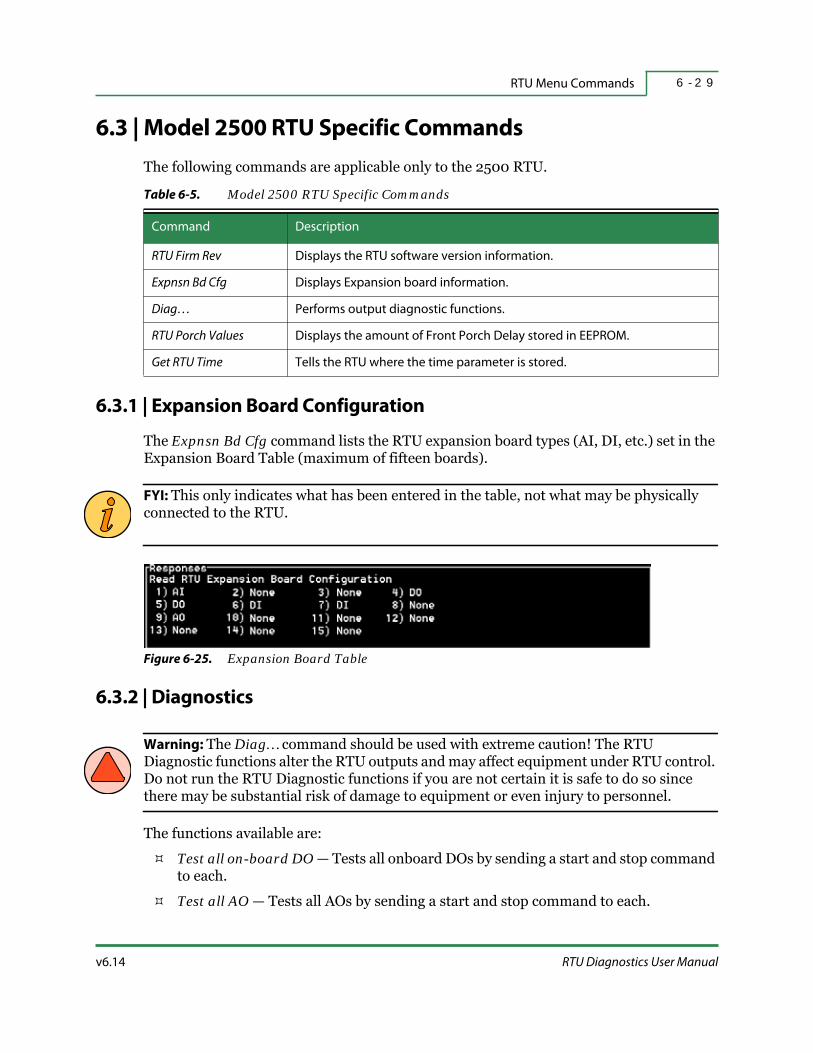
v6.14 RTU Diagnostics User Manual
RTU Menu Commands 6 - 2 9
6.3 | Model 2500 RTU Specific Commands
The following commands are applicable only to the 2500 RTU.
6.3.1 | Expansion Board Configuration
The Expnsn Bd Cfg command lists the RTU expansion board types (AI, DI, etc.) set in the Expansion Board Table (maximum of fifteen boards).
FYI: This only indicates what has been entered in the table, not what may be physically connected to the RTU.
Figure 6-25. Expansion Board Table
6.3.2 | Diagnostics
Warning: The Diag… command should be used with extreme caution! The RTU Diagnostic functions alter the RTU outputs and may affect equipment under RTU control. Do not run the RTU Diagnostic functions if you are not certain it is safe to do so since there may be substantial risk of damage to equipment or even injury to personnel.
The functions available are:
Test all on-board DO — Tests all onboard DOs by sending a start and stop command to each.
Test all AO — Tests all AOs by sending a start and stop command to each.
Table 6-5. Model 2500 RTU Specific Commands
Command Description
RTU Firm Rev Displays the RTU software version information.
Expnsn Bd Cfg Displays Expansion board information.
Diag… Performs output diagnostic functions.
RTU Porch Values Displays the amount of Front Porch Delay stored in EEPROM.
Get RTU Time Tells the RTU where the time parameter is stored.

Model 2500 RTU Specific Commands6 - 3 0
HSQ Technology v6.14
Test all DV — Tests all DVs by sending a start and stop command to each.
Run on-board diagnostics — Sends a start and stop command to the RTU and reports whether the RTU passed.
6.3.3 | RTU Porch Values
The RTU Porch Values command displays the amount of the front porch delay (in milliseconds). The front porch is the amount of time that RTUDiag needs to stabilize the communications channel between itself and the RTU. The current delay is displayed in the title lines at the top of the screen.
6.3.4 | Get RTU Time
The Get RTU Time command retrieves and displays the RTU time. Some older 2500 RTUs keep the time parameter in a non-standard address. RTUDiag must be told how this RTU treats time. The following prompt displays:
Use non-standard time address [Y|N](N):If the RTU uses a standard time address, accept the default. If the RTU uses a non-standard address, enter <Y>. The following additional prompt appears:
RTU Time Address:Enter the address in the RTU where the time parameter value is kept. RTUDiag displays the time in the Responses window.
6.3.5 | Clear RTU Non-Volatile Memory
The Clear RTU Non-Volatile command clears the RTU EEPROM immediately after the command is sent. Before using this command, it is recommended that a replacement file be ready for downloading.
6.3.6 | Run Non-Volatile Test
The Run EEPROM Test command performs a non-destructive Read/Write test of the RTU EEPROM. This is the same test initiated by the Test switch on the RTU Control Panel of the 2500/86. During the EEPROM test, the “RTU Diagnostics Passed” indicator LED flashes slowly. If the test fails, the indicator LED goes out. If the test is completed successfully, the light stops blinking and remains steady.
6.3.7 | Abort Non-Volatile Test
The Abort EEPROM Test command immediately terminates the RTU EEPROM test.

7 - 1v6.14 RTU Diagnostics User Manual
S E C T I O N 7
POINT MENU COMMANDS
The Point… menu commands allow you to load and edit point definitions and perform diagnostics using either the point number or its acronym. This section details how to manage the points database and includes descriptions for the following:
Overview
Point Defaults
Defining Points
Load and Save Definitions
Working With the Points Database
Working With the RTU
Displaying and Deleting Definitions
Specific RTU Commands
FYI: Point definitions and their acronyms are only available if you have manually defined and saved them. Typically, this is never done and only point numbers are used when working with RTUDiag.

Overview7 - 2
HSQ Technology v6.14
7.1 | Overview
The Point... command opens a menu that sets up and loads the points database.
Figure 7-1. Point… Menu Window
This allows you to identify points and perform diagnostics either by point number or acronym. Using the <Alt-u> hotkey opens a dialog box that lists the Sensor Types that you can use for testing. It is possible to make up a custom database by defining a unique set of points, then you can use the database for testing Point Control and at every Enter point… command.
Table 7-1. Point Menu Commands
Command Description Shortcut Key
QUIT Exits to the Command Menu. <q> or <Esc>
Pt Default… Sets the default parameters for point types. <p>
AI Define Defines Analog Input points. <a>
CI Define Defines Counter Input points. <c>
DV Define Defines Device points. <v>
DI Define Defines Digital Input points. <d>
SP Define Defines setpoints. <s>
AO Define Defines Analog Output points. <o>
Load Host DefsLoads the converted Host points database.
FYI: This feature is currently disabled.<h>
Select Subset Isolates the database by point type. <b>
Load Session Defs Loads an SES file. <l>
Point Control Tests the database by point acronym. <n>

v6.14 RTU Diagnostics User Manual
Point Menu Commands 7 - 3
You can save the custom database for use in a future RTU Diagnostics testing session. If you do not reinitialize the RTU after custom point definitions are sent to it, the Host database and the RTU may become out of sync.
Once a database is established, tests can be performed on each point. From the Command Menu, select a test to perform and then select a specific point (refer to Section 4, “Diagnostic Commands” for details). RTUDiag displays all appropriate tests (if different from the previous selection) for that point type.
Each time a command is issued, it is sent to the RTU in a separate frame. To send multiple commands in a single frame, refer to “String” on page 5-2.
While a command is being processed, the message Sending command… is displayed and verification of the action is shown in the Responses window.
Save Session Defs Saves the current points definitions as an SES file. <i>
Menu Format Sets acronym display with or without values. <m>
Purge Defs Erases the current points definitions. <g>
Initialize RTU Sends an initialize command to the RTU. <z>
Delete Pnt Def Deletes a specified point type definition. <t>
Read All RTU Sends a Read All command to the RTU. <e>
Read Def From RTURetrieve point definitions information from the RTU.
FYI: This feature is currently disabled.<f>
Display Acro Defs Displays information about selected points. <y>
Download Defs To RTU Sends the current database to the RTU being tested. <w>
Table 7-1. Point Menu Commands (continued)
Command Description Shortcut Key
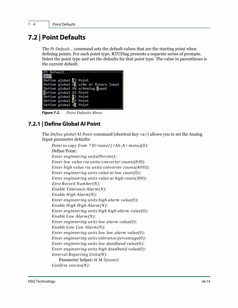
Point Defaults7 - 4
HSQ Technology v6.14
7.2 | Point Defaults
The Pt Default… command sets the default values that are the starting point when defining points. For each point type, RTUDiag presents a separate series of prompts. Select the point type and set the defaults for that point type. The value in parentheses is the current default.
Figure 7-2. Point Defaults Menu
7.2.1 | Define Global AI Point
The Define global AI Point command (shortcut key <a>) allows you to set the Analog Input parameter defaults:
Point to copy from ? [0=none] (<Alt-A> menu)(0):Define Point:Enter engineering units(Percent):Enter low value rtu units/converter counts(819):Enter high value rtu units/converter counts(4095):Enter engineering units value at low count(0):Enter engineering units value at high count(100):Zero Record Number(N):Enable Tolerance Alarm(N):Enable High Alarm(N):Enter engineering units high alarm value(0):Enable High High Alarm(N):Enter engineering units high high alarm value(0):Enable Low Alarm(N):Enter engineering units low alarm value(0):Enable Low Low Alarm(N):Enter engineering units low low alarm value(0):Enter engineering units tolerance percentage(0):Enter engineering units low deadband value(0):Enter engineering units high deadband value(0):Interval Reporting Units(N):
Parameter helper: H M S(none)Confirm entries(N):

v6.14 RTU Diagnostics User Manual
Point Menu Commands 7 - 5
7.2.2 | Define Global DV with No or Binary Input
The Define global DV w/No or Binary Input command (shortcut key <v>) allows you to set the Device parameter defaults:
Point to copy from ? [0=none] (<Alt-A> menu)(0):Input address[0=none] (0):Define Point:Command on text(Start):Command off text(Stop):Zero Record Number(N):COS reporting(N):Confirm entries(N):
7.2.3 | Define Global DV with Analog Input
The Define global DV w/Analog Input command (shortcut key <i>) allows you to set the Device parameter defaults:
Point to copy from ?[0=none] (<Alt-A> menu)(0):Input address[0=none] (0):Define Point:Enter engineering units(Seconds):Enter low value rtu units/converter counts(0):Enter high value rtu units/converter counts(4095):Enter engineering units value at low count(0):Enter engineering units value at high count(4095):Zero Record Number(N):Enable Tolerance Alarm(N):Confirm entries(N):

Point Defaults7 - 6
HSQ Technology v6.14
7.2.4 | Define Global DI Point
The Define global DI Point command (shortcut key <d>) allows you to set the Digital Input parameter defaults:
Point to copy from ?[0=none] (<Alt-A> menu)(0):Define Point:Enter device on text(On):Enter device off text(Off):Device on status(1):Device off status(0):Enable High Alarm(N):Enable Low Alarm(N):COS reporting(N):Set Interval Reporting Units or Disable(N):
Parameter helper: H M S(none)Time Interval(0):Zero Record Number(N):Confirm entries(N):
7.2.5 | Define Global CI Point
The Define global CI Point command (shortcut key <c>) allows you to set the Counter Input parameter defaults:
Point to copy from ?[0=none] (<Alt-A> menu)(0):Set counter units:Enable Interval Reporting(N):
Parameter helper: H M S(none)Time Interval(0):Enter engineering units(Counts):Enter engineering units per count(1):Zero Record Number(N):Confirm Entries(N):

v6.14 RTU Diagnostics User Manual
Point Menu Commands 7 - 7
7.2.6 | Define Global SP Point
The Define global SP Point command (shortcut key <s>) allows you to set the setpoint parameter defaults:
Point to copy from ?[0=none] (<Alt-A> menu)(0):Input address[0=none](0):Define Point:Enter output low limit (engineering units)(0):Enter output high limit(engineering units)(100):Enter engineering units(Percent):Enter low value rtu units/converter counts(819):Enter high value rtu units/converter counts(4095):Enter engineering units value at low count(0):Enter engineering units value at high count(100):Zero Record Number(N):Enable Tolerance Alarm(N):Confirm entries(N):
7.2.7 | Define Global AO Point
The Define global AO Point command (shortcut key <o>) allows you to set the Analog Output parameter defaults:
Point to copy from ? [0=none] (<Alt-A> menu)(0):Input address[0=none](0):Define Point:Enter output low limit (engineering units)(4):Enter output high limit(engineering units)(20):Enter engineering units(ma):Enter low value rtu units/converter counts(0):Enter high value rtu units/converter counts(4095):Enter engineering units value at low count(4):Enter engineering units value at high count(20):Zero Record Number(N):Confirm entries(N):

Defining Points7 - 8
HSQ Technology v6.14
7.3 | Defining Points
In addition to defining the defaults for each type of point, you can set the parameters for an individual or a range of points. The prompts are the same as when setting the defaults, except where noted below. The value in parentheses is the default.
FYI: The last parameter allows you to assign an acronym for the point. This is the only way to be able to use acronyms (e.g., <Alt-A> menu) in future sessions.
7.3.1 | AI Define
The first prompt requires you to enter a point number (to create a new point) or select an acronym from the <Alt-A> menu (to edit an existing point). For example:
Enter point number (<Alt-A> menu):Point to copy from ? [0=none] (<Alt-A> menu)(0):
If you enter <Y> at the prompt:Skip alarms and downloading to RTU(Y):
You can configure the following parameters:Enter engineering units(Percent):Enter low value rtu units/converter counts(819):Enter high value rtu units/converter counts(4095):Enter engineering units value at low count(0):Enter engineering units value at high count(100):Zero Record Number(N):Confirm entries(N):
If you enter <N> at the prompt:Skip alarms and downloading to RTU(Y):

v6.14 RTU Diagnostics User Manual
Point Menu Commands 7 - 9
You can configure the additional parameters:Enable Tolerance Alarm(N):Enable High Alarm(N):Enter engineering units high alarm value(0):Enable High High alarm(N):Enter engineering units high high alarm value(0):Enable Low Alarm(N):Enter engineering units low alarm value(0):Enable Low Low Alarm(N):Enter engineering units low low alarm value(0):Enter engineering units tolerance percentage(0):Enter engineering units low deadband value(0):Enter engineering units high deadband value(0):Interval Reporting Units(N):Confirm entries(N):Download definition to RTU(N):Enter acronym for point 1 (NONAME-AI1):
7.3.2 | CI Define
The first prompt requires you to enter a point number (to create a new point) or select an acronym from the <Alt-A> menu (to edit an existing point). For example:
Enter point number (<Alt-A> menu):Point to copy from ? [0=none] (<Alt-A> menu)(0):
If you enter <Y> at the prompt:Skip alarms and downloading to RTU(Y):
You can configure the following parameters:Enter engineering units(Percent):Enter engineering units(Counts):Enter engineering units per count(1):Zero Record Number(N):Confirm Entries(N):
If you enter <N> at the prompt:Skip alarms and downloading to RTU(Y):
You can configure the additional parameters:Enable Interval Reporting(N):Time Interval(0):Download definition to RTU(N):Enter acronym for point 1 (NONAME-CI1):

Defining Points7 - 1 0
HSQ Technology v6.14
7.3.3 | DV Define
There are two types of DV definitions.
7.3.3.1 | Binary or No Associated Input
The first prompt requires you to enter a point number (to create a new point) or select an acronym from the <Alt-A> menu (to edit an existing point). For example:
Enter point number (<Alt-A> menu):Point to copy from ? [0=none] (<Alt-A> menu)(0):
If you enter <Y> at the prompt:Skip alarms and downloading to RTU(Y):
You can configure the following parameters:Input address[0=none] (0):Command on text(Start):Command off text(Stop):Zero Record Number(N):COS reporting(N):Confirm entries(N):Enter acronym for point 1 (NONAME-DV1):
If you enter <N> at the prompt:Skip alarms and downloading to RTU(Y):
You can configure the additional parameters:Download definition to RTU(N):
7.3.3.2 | Associated Analog Input
The first prompt requires you to enter a point number (to create a new point) or select an acronym from the <Alt-A> menu (to edit an existing point). For example:
Enter point number (<Alt-A> menu):Point to copy from ? [0=none] (<Alt-A> menu)(0):
If you enter <Y> at the prompt:Skip alarms and downloading to RTU(Y):

v6.14 RTU Diagnostics User Manual
Point Menu Commands 7 - 1 1
You can configure the following parameters:Input address[0=none] (0):Enter engineering units(Seconds):Enter low value rtu units/converter counts(0):Enter high value rtu units/converter counts(4095):Enter engineering units value at low count(0):Enter engineering units value at high count(4095):Zero Record Number(N):Confirm entries(N):Enter acronym for point 1 (NONAME-DV1):
If you enter <N> at the prompt:Skip alarms and downloading to RTU(Y):
You can configure the additional parameters:Enable Tolerance Alarm(N):Download definition to RTU(N):
7.3.4 | DI Define
The first prompt requires you to enter a point number (to create a new point) or select an acronym from the <Alt-A> menu (to edit an existing point). For example:
Enter point number (<Alt-A> menu):Point to copy from ? [0=none] (<Alt-A> menu)(0):
If you enter <Y> at the prompt:Skip alarms and downloading to RTU(Y):
You can configure the following parameters:Enter device on text(On):Enter device off text(Off):Device on status(1):Device off status(0):Confirm entries(N):Enter acronym for point 1 (NONAME-DI1):
If you enter <N> at the prompt:Skip alarms and downloading to RTU(Y):
You can configure the additional parameters:Enable High Alarm(N):Enable Low Alarm(N):COS reporting(N):Set Interval Reporting Units or Disable(N):Time Interval(0):Zero Record Number(N):Download definition to RTU(N):
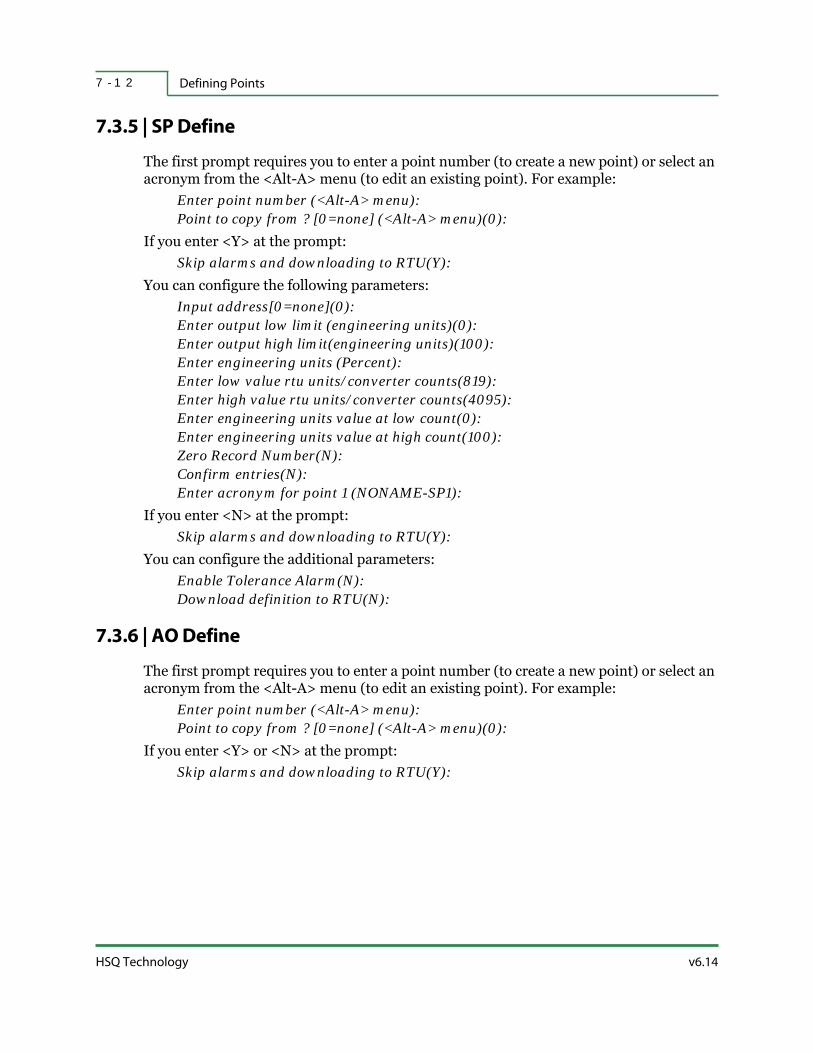
Defining Points7 - 1 2
HSQ Technology v6.14
7.3.5 | SP Define
The first prompt requires you to enter a point number (to create a new point) or select an acronym from the <Alt-A> menu (to edit an existing point). For example:
Enter point number (<Alt-A> menu):Point to copy from ? [0=none] (<Alt-A> menu)(0):
If you enter <Y> at the prompt:Skip alarms and downloading to RTU(Y):
You can configure the following parameters:Input address[0=none](0):Enter output low limit (engineering units)(0):Enter output high limit(engineering units)(100):Enter engineering units (Percent):Enter low value rtu units/converter counts(819):Enter high value rtu units/converter counts(4095):Enter engineering units value at low count(0):Enter engineering units value at high count(100):Zero Record Number(N):Confirm entries(N):Enter acronym for point 1 (NONAME-SP1):
If you enter <N> at the prompt:Skip alarms and downloading to RTU(Y):
You can configure the additional parameters:Enable Tolerance Alarm(N):Download definition to RTU(N):
7.3.6 | AO Define
The first prompt requires you to enter a point number (to create a new point) or select an acronym from the <Alt-A> menu (to edit an existing point). For example:
Enter point number (<Alt-A> menu):Point to copy from ? [0=none] (<Alt-A> menu)(0):
If you enter <Y> or <N> at the prompt:Skip alarms and downloading to RTU(Y):

v6.14 RTU Diagnostics User Manual
Point Menu Commands 7 - 1 3
You can configure the following parameters:Input address[0=none](0):Enter output low limit (engineering units)(4):Enter output high limit(engineering units)(20):Enter engineering units(ma):Enter low value rtu units/converter counts(0):Enter high value rtu units/converter counts(4095):Enter engineering units value at low count(4):Enter engineering units value at high count(20):Zero Record Number(N):Confirm entries(N):Enter acronym for point 1 (NONAME-AO1):
Load and Save Definitions7 - 1 4
HSQ Technology v6.14
7.4 | Load and Save Definitions
7.4.1 | Load Host Definitions
This feature is currently not available.
The Load Host Defs command loads the Host points database. It is assumed that this database is located in the same directory as RTUDiag (C:\RTU\RTUDIAG) and that it has already been converted. RTU Diagnostics automatically purges any existing definitions before loading this file.
7.4.2 | Load Session Definitions
The Load Session Defs command lets you load a previously created points definition database file. If points have not been manually defined for this RTU, the following message appears at system startup:
No points or acronyms defined for this RTUThe saved session file is located in the same directory as RTUDiag (C:\RTU\RTUDIAG) and has an SES file extension. RTUDiag automatically purges any existing definitions before loading the file specified.
7.4.3 | Save Session Definitions
The Save Session Defs command saves the current points database to a named file. RTU Diagnostics automatically adds the SES file extension and saves the file in the same directory as RTUDiag (C:\RTU\RTUDIAG). The file can then be loaded for use during future sessions.

v6.14 RTU Diagnostics User Manual
Point Menu Commands 7 - 1 5
7.5 | Working With the Points Database
7.5.1 | Select Subset
Figure 7-3. Select Subset Menu
The Select Subset command delineates the point database by point type, making only the point type selected available for testing. All other points in the point database are temporarily ignored.
When Wildcard is selected, you are prompted to enter a wildcard expression. Enter the acronym/wildcard combination that identifies the point(s) to test. Refer to “Wildcards” on page 2-8 for more information.
7.5.2 | Point Control
The Point Control command opens a dialog box that displays the points database for testing. All points are available unless a subset has been preselected. In that case, only those points in the subset are displayed. The acronyms are organized alphanumerically in groups of twelve. If the menu format “Acros w/values” was selected, the current values are also displayed. Each screen or page also includes the following commands:
QUIT — Returns to the Point… menu.
Repeat — Repeats the last test.
More — Cycles through the pages in the list.
Poll — Requests RTU command responses or COS awaiting transmission.
Figure 7-4. Point Control Summary

Working With the Points Database7 - 1 6
HSQ Technology v6.14
When you select an acronym, a dialog box opens that summarizes the point definition and offers the appropriate diagnostics. For specific information about each test, refer to “Read Commands” on page 4-2 and “Write Commands” on page 4-5.
7.5.3 | Menu Format
The Menu Format command determines whether the current status is shown with the acronym when the points are displayed. The choices are:
Acros w/values — displays the acronym with its value.
Acros only — displays the acronym without its value.
Table 7-2. Acronym Commands
Point Type Commands
AI and DI points
Read AI/DI
Write AI/DI
Enable AI/DI
Disable AI/DI
AO and SP pointsRead AO/SP
Write AO/SP
CI points
Read CI
Reset CI
Enable CI
Disable CI
DV points
Read DV
Flash DV
Raise DV
Lower DV
Stop DV
Release DV
Enable DV
Disable DV

v6.14 RTU Diagnostics User Manual
Point Menu Commands 7 - 1 7
7.6 | Working With the RTU
7.6.1 | Purge Definitions
The Purge Defs command erases the point definitions stored in the RTU memory. This command only purges the non-volatile storage on the RTU. The point definitions stay in RAM until the RTU is rebooted. Saved files remain and can be reloaded.
Warning: There is no confirmation step for this command. Once you purge the definitions the change is permanent and cannot be recovered. Please make sure this is the intended action.
7.6.2 | Initialize RTU
The Initialize RTU command forces the RTU to erase all point definitions and initiate a download from the MISER Host (if it is online). Please refer to “Initialize RTU” on page 6-3 for details and warnings about this command.
7.6.3 | Read All RTU
The Read All RTU command generates a report of all the points defined in the RTU.
FYI: RTUDiag must be set to “Host ID - COS reporting” for this feature to work properly. See “Diag ID-COS Enable” on page 3-7 for details.
7.6.4 | Download Definitions to RTU
The Download Defs To RTU command sends the current points definition database to the RTU being tested.
Do not download point definitions unless the Host point file has been converted.
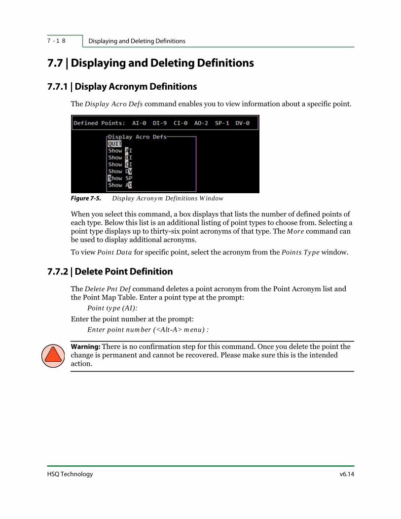
Displaying and Deleting Definitions7 - 1 8
HSQ Technology v6.14
7.7 | Displaying and Deleting Definitions
7.7.1 | Display Acronym Definitions
The Display Acro Defs command enables you to view information about a specific point.
Figure 7-5. Display Acronym Definitions Window
When you select this command, a box displays that lists the number of defined points of each type. Below this list is an additional listing of point types to choose from. Selecting a point type displays up to thirty-six point acronyms of that type. The More command can be used to display additional acronyms.
To view Point Data for specific point, select the acronym from the Points Type window.
7.7.2 | Delete Point Definition
The Delete Pnt Def command deletes a point acronym from the Point Acronym list and the Point Map Table. Enter a point type at the prompt:
Point type (AI):Enter the point number at the prompt:
Enter point number (<Alt-A> menu) :
Warning: There is no confirmation step for this command. Once you delete the point the change is permanent and cannot be recovered. Please make sure this is the intended action.

v6.14 RTU Diagnostics User Manual
Point Menu Commands 7 - 1 9
7.8 | Specific RTU Commands
7.8.1 | Read Definitions From RTU
This command is only applicable for 25x86 RTUs (not all versions).
The Read Def From RTU command reads AI, DI, and CI point definitions directly from the RTU. For this to work, the point definitions must first be defined in the RTU Point Map. Choose from the list of point types the one you want to read from the RTU. Enter the point number or acronym at the prompt.
If the point number is outside the range of physically possible point numbers for that particular HSQ board type, the Responses window will display:
Querying RTU for point - Command rejected by RTUIf the point number is outside the range of allowable point numbers for that particular HSQ board type, as defined in the RTU Point Map, the Responses window will display:
POINT UNDEFINED
7.8.2 | RTU AI Scale/Units (2500 RTU Only)
The RTU AI Scale/Units command reads AI scale/unit parameters set in the RTU EEPROM. Analog inputs may be configured as single-ended or differential and may be unipolar or bipolar current loop (4 - 20 mA), 0 to 5 V, and 0 to 10 V, ± 5 V, or ±10 V. At the prompt, enter a single point number, a range of point numbers, a single point acronym, or a partial acronym with wildcard characters.
The display is organized alphanumerically, in groups of twelve. Select a point type from the list, then use <Alt-a> to locate a point by acronym. A table of AI point specific information will display.

Specific RTU Commands7 - 2 0
HSQ Technology v6.14

8 - 1v6.14 RTU Diagnostics User Manual
S E C T I O N 8
RTU POINT MAP
The HSQ remote terminal unit (RTU) requires a Point Map reflecting the board/module configuration. The configuration information includes: board types, board addressing, point types, etc.
This section describes:
RTU Point Map
Building an RTU Point Map
Point Tables
Point Map for Multiplexing PLC Points
FYI: Throughout this section, the term board is meant to refer to either an Interface Board, a Model 2500 Series Expansion Board, an HSQ 3010, or 6000/6200 series module.
FYI: Most of the commands, functions, and menus in this section apply to the HSQ Model 25x86 and 6000/1911/1110 RTUs. However, some commands are specific to individual models. Information for the HSQ Model 2500 and HSQ Model 2500/86 RTUs is included here for legacy users.

RTU Point Map8 - 2
HSQ Technology v6.14
8.1 | RTU Point Map
The RTU monitors and controls sensors and controllers that are designated in the system as points. A point can represent an actual physical device or a calculated value. Each point has an address, identifier, and specific operating parameter associated with the board configuration and termination. In the Point Map, all points are grouped by type and location.
The RTU requires a Point Map that reflects the RTU Point and Board configurations. This map is created and edited using the Point Map… command (RTU… > RTU Hrdwr Cnfg… > Point Map…). Refer to “Point Map” on page 6-9 for details.
Points are either analog or binary:
Analog points include analog inputs (AI), analog outputs (AO), and setpoints (SP).
Binary points include digital inputs (DI), devices (DV), and counter inputs (CI).
The RTU Point Map establishes an association between point addresses, point operating parameters, and the hardware configuration of the I/O boards. Also, it specifies addresses in the RTU memory for virtual points (points that are used for calculations and not connected to any hardware).
Entries in the Point Map specify:
Point type (AI, CI, DI, AO, DV, and SP)
Point address range in the database
HSQ board type
Board address
Bus address
Analog Input Attribute Table and Device Table
The Point Map is stored in non-volatile storage and loaded into RAM when the RTU boots up. The RTU Diagnostics software automatically adds a BRD extension to the file when it is created.
8.1.1 | Point Map Modification Error Message
Warning: You will encounter an error if you attempt to modify a Point Map entry that has a point table associated with it and then subsequently change the board type. Do not change the board type of a Point Map entry if the point table is not empty.

v6.14 RTU Diagnostics User Manual
RTU Point Map 8 - 3
Figure 8-1. Point Map Error Message
In the example above, the board type associated with the point entry is an HSQ 6017 module and an attempt is made to change the board type to a 2508 expansion board.
When you get this error message you have two options:
D — Delete the existing point table and create a new blank table.
A — Abort the attempted change. You will not be given an opportunity to modify or view the table since it is in conflict with the primary Point Map entry.

Building an RTU Point Map8 - 4
HSQ Technology v6.14
8.2 | Building an RTU Point Map
You can create a Point Map by loading and modifying an existing RTU Point Map (see “Load Point Map from File” on page 6-9) or by loading and modifying the Default Table (see “Load Default Point Map” on page 6-9).
8.2.1 | Point Map Command Keys
Figure 8-2. Point Map Command Keys
The Point Map screen displays a row of commands, in addition to the table rows and columns. These commands allow you to add, modify, or delete any row or entry in the RTU Point Map.
Table 8-1. Point Map Command Descriptions
Command Description
<INS>
The <Insert> key places a new row into the existing Point Map immediately after
the one currently highlighted. The new row will display information similar to its
predecessor but with the point numbers incremented appropriately.
<DEL> The <Delete> key erases the currently highlighted row.
<RET>
The <Return> (<Enter>) key selects the highlighted row, creating a row entry
screen that is configurable. After selecting the row to modify, the <Return> key
selects an item from the resulting dialog box.
<ESC> The <Escape> key exits to the next higher level menu.
Up and Down
arrows
The up and down arrow keys move the row selection highlight from table row to
table row.
Right and Left
arrows
The right and left arrow keys move the row entry highlight (indicating the
currently active entry) from row entry to row entry after the row is selected.

v6.14 RTU Diagnostics User Manual
RTU Point Map 8 - 5
Figure 8-3. Point Map Row Entry Dialog Box
To select a row on the Point Map screen, move the row highlight with the arrow keys until it is on the desired row. Press <Enter> to select the row and display the Row Entry dialog box. The left and right arrow keys move the highlight to each entry.
Figure 8-4. Selection Parameter Helper Box
Press <Enter> to display a dialog box used to enter or modify parameters. Additionally, a Parameter Helper box displays showing the available choices.

Building an RTU Point Map8 - 6
HSQ Technology v6.14
8.2.2 | Point Map Screen
The RTU Point Map displays seven columns. If the Default Table is loaded, the table contains one row entry. A saved file may display multiple row entries. Each table row contains the information needed to completely identify a board (e.g., board number, point type, board address, etc.).
The column headings are:
PT TYPE — “Point Types” on page 8-6.
FIRST PT – LAST PT — “First Point – Last Point” on page 8-6.
BD TYPE — “Board Type” on page 8-7.
BUS — “Expansion Bus” on page 8-9.
SWITCH — “Board Address Switches” on page 8-9.
RIO ID — “RIO ID” on page 8-10.
8.2.2.1 | Point Types
The Point Map supports six different point types:
DI — Digital Input
AI — Analog Input
CI — Counter Input
DV — Device (some digital points have a software component called a DV and a hardware component called a DO).
AO — Analog Output
SP — Setpoint
Related Docs: 25x86 Logic Processor User Manual, 25x86 Logic Processor Software has more information about DV points. MISER Operator Manual, Point Display has more information about point types.
8.2.2.2 | First Point – Last Point
Each HSQ expansion board (i.e., 2507, 2508, etc.) is configurable for a maximum number of points.
Related Docs: 25x86 Logic Processor User Manual, 25x86 Logic Processor Software has more information about standard point addressing.

v6.14 RTU Diagnostics User Manual
RTU Point Map 8 - 7
FYI: Any given point type can appear on multiple boards, but the same point address (or range) cannot overlap. For example, a DI point, address (number) 14, can only be assigned to one board.
An error message displays if the First Point address is greater than the Last Point address.
8.2.2.3 | Board Type
To properly build the RTU Point Map, the HSQ model number for each board installed is required. The board name, model number, and point type are printed on the front of each expansion board in large typeface or listed on the front sticker of the HSQ 3010 and 6000/6200 series modules. The supported board types are:
Table 8-2. Supported Board Types
Board Type Point Type and Count
2507 AO – 4
2508
AI – 32
DI – 32
(The HSQ 2535 DI to AI adapter only works on the left side of the 2508 board.)
If a 2508 AI board is in the Point Map as DIs, it must also be in the Point Map as
AIs.
2509 DI – 32 *
2510 DO – 64 (sink type)
2533 DO – 32
2534DI – 32 *
(CI – 32)
2548 DO – 16
2569
DI – 16 *
DO – 16
(CI – 16)
* If a 2509, 2534, or 2569 DI board is in the Point Map as CIs, they must also be in the Point Map as
DIs.
1802 N/A
2587TTL DI – 64
TTL CI – 64
MUX1-MUX10
Point Multiplexers are inexpensive single board microcomputers that can
interface with points at remote equipment locations. The RTU polls the MUX for
data. Typically, MUX functions are restricted to reporting values and accepting
commands. Refer to “Enable/Disable MUX” on page 4-13 for more information.

Building an RTU Point Map8 - 8
HSQ Technology v6.14
AUX DI Recommended Point Address – 225-256
AUX DV (DO) Recommended Point Address – 225-236
AUX AI Recommended Point Address – 225-232
AUX CI Recommended Point Address 225-236
VIRTUALAI, DI, DV, SP. Virtual points have no physical hardware connections. Read/write
operations are performed in software only.
PLC PLC Point Map entries are used to map PLC registers.
6015 AI – 7
6017AI – 8
DO – 2
6018AI (thermocouple) – 8
DO – 8
6024
AI – 6
AO – 2
DI – 2
DO – 2
6050DI – 12
DO – 6
6051
DI – 12
CI – 2
DO – 2 (sink type)
6052DI – 8
DO – 8
6060DI – 6
DO (relay) – 6
6066DI – 6
DO (power relay) – 6
3718H N/A
3718HO N/A
6217 AI – 8
6224AO – 4
DI – 4 (dry contact only)
Table 8-2. Supported Board Types (continued)
Board Type Point Type and Count

v6.14 RTU Diagnostics User Manual
RTU Point Map 8 - 9
RTU Diagnostics allows you to enter any of the choices displayed in the Parameter Helper box. However, incorrect point types for the selected board will be rejected and when you attempt to download the Point Map to the RTU it will result in the error message:
Board conflicts found - download or abort [D|A](A):Abort is recommended in this case. Specific error messages are logged in the Responses window.
8.2.2.4 | Expansion Bus
Each expansion board is connected to an 8601 Expansion Bus Interface Board. There can be up to two 8601 boards jumpered as Bus 1 or Bus 2. RIO ID is used for the HSQ 3010 and 6000/6200 series modules. When you select “Bus”, you are given the prompt:
Bus/Switch or Custom Address[B|C](B):Enter B for Bus or C for Custom Address (RIO ID). If you enter <b>, you receive the prompt:
Board Bus [1-2](1):Enter the applicable Board Bus number. If you enter <c>, you receive the prompt:
Custom Board Address(336):Enter the HSQ 3010 or 6000/6200 series RIO module address. See “Remote Input/Output Configuration” on page 6-22.
8.2.2.5 | Board Address Switches
Each expansion board must have a unique address so the RTU can identify it. The address is set on the board using four DIP switches labeled BOARD ADDRESS. Switch positions numbered 1, 2, 3, and 4 correspond to values of 8, 4, 2, and 1, respectively. The
6250DI – 8
DO – 7 (sink type)
6251 DI – 16
6256 DO – 16 (sink type)
6260 DO (relay) – 6
6266DI – 4
DO (relay) – 4
3010
AI – 8
DI – 8
DO – 4
Table 8-2. Supported Board Types (continued)
Board Type Point Type and Count
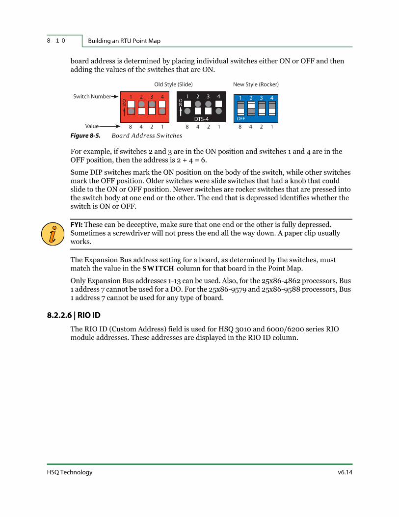
Building an RTU Point Map8 - 1 0
HSQ Technology v6.14
board address is determined by placing individual switches either ON or OFF and then adding the values of the switches that are ON.
Figure 8-5. Board Address Switches
For example, if switches 2 and 3 are in the ON position and switches 1 and 4 are in the OFF position, then the address is 2 + 4 = 6.
Some DIP switches mark the ON position on the body of the switch, while other switches mark the OFF position. Older switches were slide switches that had a knob that could slide to the ON or OFF position. Newer switches are rocker switches that are pressed into the switch body at one end or the other. The end that is depressed identifies whether the switch is ON or OFF.
FYI: These can be deceptive, make sure that one end or the other is fully depressed. Sometimes a screwdriver will not press the end all the way down. A paper clip usually works.
The Expansion Bus address setting for a board, as determined by the switches, must match the value in the SWITCH column for that board in the Point Map.
Only Expansion Bus addresses 1-13 can be used. Also, for the 25x86-4862 processors, Bus 1 address 7 cannot be used for a DO. For the 25x86-9579 and 25x86-9588 processors, Bus 1 address 7 cannot be used for any type of board.
8.2.2.6 | RIO ID
The RIO ID (Custom Address) field is used for HSQ 3010 and 6000/6200 series RIO module addresses. These addresses are displayed in the RIO ID column.
248 1
321 4ON
Old Style (Slide) New Style (Rocker)
248 1
321 4ON
DTS-4 OFF
321 4
248 1
Switch Number
Value

v6.14 RTU Diagnostics User Manual
RTU Point Map 8 - 1 1
Figure 8-6. RIO ID Screen
8.2.3 | Mapping a Point Type
1. Press <Insert> to insert a new row in the Point Map.
2. Using the arrow keys, highlight the new row and press <Enter>.
3. Again using the arrow keys, highlight each field you want to modify and press <Enter>.
4. Select the point type (PT TYPE) that is compatible for the board.
5. Select the proper first (FIRST PT) and last (LAST PT) point numbers.
6. Select the appropriate board type (BD TYPE).
7. Select the bus and switch the board is attached to (BUS and SWITCH) or if mapping a module, the Custom Address (RIO ID).
8. When you are finished, press <Esc>.
8.2.3.1 | Mapping Multiple Point Types on a Single Board
Some boards support more than one type of point.
1. Follow the steps above to map the first type of point.
2. Highlight that row and press <Insert>. A duplicate of that board is entered in the Point Map (with the point numbers incremented).
3. Edit the point type and the first and last point fields.
4. Leave the bus and switch or RIO ID fields the same.
5. When you are finished, press <Esc>.

Building an RTU Point Map8 - 1 2
HSQ Technology v6.14
Things to remember about configuring board types and points:
Each board must have a unique address.
Point addresses on the same board may not overlap.
Pick only the appropriate point types for the board you are configuring.
8.2.4 | Mapping Virtual Points
Virtual points can be an AI, DI, DV, or AO. The process for mapping virtual points is the same as other types of points, except you choose VIRTUAL for the board type and you do not need to configure the Bus, Switch, or RIO ID.
Figure 8-7. Virtual Point in the Point Map
8.2.5 | Mapping AUX Points
AUX points can be DI, DV (DO), or AI. Using the insert function, add two additional boards to the list. Use the edit function to first define the point type, either DI or DV, then define the board type as AUX. Define a range of points:
AUX DI – 225-256
AUX DO – 225-236
AUX AI – 225-232
Related Docs: Specific AUX Point addressing is discussed in 25x86 Logic Processor User Manual, Standard Point Addressing.

v6.14 RTU Diagnostics User Manual
RTU Point Map 8 - 1 3
8.2.6 | Mapping Setpoints
Using the insert function, add a board to the list. Use the edit function to first define the point type as SP (setpoint), then define the board type as VIRTUAL and define a range of points. You do not need to configure the Bus, Switch, or RIO ID.
Figure 8-8. Setpoint in the Point Map
Setpoints are defined in either engineering units or converter counts (in “SP Define” on page 7-12). You can use the <Alt-u> hot key to bring up the Sensor Type list and convert engineering units to converter counts. Refer to Table 2-2 on page 2-6 for details.
8.2.7 | Exiting the Point Map
To exit the Point Map, press <Esc> from the RTU Point Map main screen. A secondary exit menu displays the following choices:
Save to file and continue
Download to RTU
Exit and lose unsaved changes
Cancel
Best Practices: It is a good idea to save the Point Map using the Save to file and continue option. Supply an appropriate file name upon request.
Download the Point Map to the RTU non-volatile storage using the Download to RTU option. Selecting this will purge the RTU Map (refer to “Purging the Point Map” on page 6-9). You are prompted with:
Confirm board list erasure in RTU [Y|N](N):

Building an RTU Point Map8 - 1 4
HSQ Technology v6.14
While the Point Map is downloading to the RTU, two messages are displayed:Downloading…Sending command…
After downloading the Point Map, you will have to select Exit and lose unsaved changes in order to exit the Point Map screen. The new Point Map will not be active until the RTU is rebooted (refer to “Reboot RTU” on page 6-4). This loads the point table from the non-volatile storage into RAM.

v6.14 RTU Diagnostics User Manual
RTU Point Map 8 - 1 5
8.3 | Point Tables
The TABLE row entry appears after a row has been selected in the main Point Map screen.
Figure 8-9. Point Table Field
It is only displayed for certain boards or points. If selected, different TABLE screens are displayed, depending on the board/point selected. AI, DV (DO), and SP have associated tables.
You can edit all of the table entries (except Acronym) in the normal way. Point table entries are not needed for points using the default settings. All the types of point tables contain:
POINT # (or DV #) — The range of available point numbers is determined by the First Point and Last Point board entries in the Point Map screen. Pressing <Insert> enters the next sequentially numbered point. Point numbers can be edited by selecting an existing row and modifying its point number. An error message displays while downloading to the RTU if the points defined in the table do not match those defined in the Point Map.
ACRONYM — Point acronyms are displayed in the Table only if they have been previously defined using commands from the Point... menu (e.g., Define AI). They cannot be set in this Table.
8.3.1 | AI Point Table
The AI Point Table contains an ATTRIBS (Attributes) parameter in addition to Point Number and Acronym. The HSQ 2508 board has a termination resistor assembly associated with Attributes that specifies the operating characteristics for each termination on the board. When using HSQ 3010 and 6000/6200 series modules, a 200 Ω resistor is used for current loop single-ended terminations and 100 KΩ resistors are used for voltage source terminations.

Point Tables8 - 1 6
HSQ Technology v6.14
Related Docs: For more information on AI points, refer to 25x86 Logic Processor User Manual, Analog Input Configurations.
8.3.1.1 | Attributes
Edit the Attributes parameter by choosing the board to edit, selecting Table, pressing <Insert>, and then <Enter> (a Parameter Helper dialog box will display to assist you). Enter the appropriate parameters at the prompt:
Channel Parameters (4US):The parameters are:
Input Signal Range — T (10 VDC), F (5 VDC), or 4 (4-20 mA or 0-4 VDC)
Bipolar (+ or –) or Unipolar (+ only) Signal — B (BIPLR) or U (UNI)
Dual Input Differential or Single-Ended — D (DUAL INP) or S (SING END)
Figure 8-10. AI Point Table Example
The example above shows Point 15 with an Input Signal Range of 10 VDC, Bipolar Signal, and Differential Termination.
The allowable combinations are:
Table 8-3. AI Point Table Attributes
Combination Description
TUS 0 to 10 VDC
TBD -10 to +10 VDC differential
TBS -10 to +10 VDC single-ended
FUS 0 to 5 VDC

v6.14 RTU Diagnostics User Manual
RTU Point Map 8 - 1 7
8.3.2 | AO Point Table
If you are configuring an HSQ-6224 module, there is the option to build an AO Point Table. It contains an ATTRIBS (Attributes) parameter in addition to the Point Number and Acronym (similar to “AI Point Table” on page 8-15). The options are:
4ma (4 - 20 mA)
5v (± 5V)
10V (± 10V)
-5v (± 5V)
-10v (± 10V)
0ma (0 - 20 mA)
The available attributes are shown in the parameter helper. The attribute must match the wiring connections on the module’s terminal block (refer to “HSQ-6224 Module” on page F-5).
Figure 8-11. AO Point Table Example
FBS -5 to +5 VDC single-ended
FBD -5 to +5 VDC differential
4US 4 to 20 mA or 0 to 4 VDC (default)
4BS -2 to +2 VDC single-ended
4BD -2 to +2 VDC differential
4UD Special 4 to 20 mA differential
Table 8-3. AI Point Table Attributes (continued)
Combination Description

Point Tables8 - 1 8
HSQ Technology v6.14
For information on setting the jumpers on 6017 and 6024 modules, refer to “HSQ-6017 Module” on page F-3 and “HSQ-6024 Module” on page F-4.
Related Docs: For information on setting the jumpers on the HSQ-3010, refer to the HSQ-3010 Ethernet I/O Module User Manual.
8.3.3 | DV Point Table
To allow flexibility in controlling digital outputs, Digital Points have a software component called a Device (DV) and a hardware component called a Digital Output (DO). Each DO board has an associated DV Table that describes the relationship of the DVs to the DOs.
When a command is issued to a Device, the DV Table determines how the command should affect the DO(s).
DV points that do not have entries in the DV Point Table default to:
STR DO — The Start DO number is the same as the DV number.
STP DO — The Stop DO number is 0.(The Start command turns the DO ON and the Stop command turns it OFF.)
DURAT — the Duration is 0 (maintained output).
MN ON — the Minimum On time is 0 (no limit).
MN OFF — the Minimum Off time is 0 (no limit).
MAX ST — the Maximum Starts per Hour is 0 (no limit).
Only DV points with non-default settings need to be in the DV Point Table.
FYI: A DV with no associated DO is a virtual DV. Commands can be issued to it, but have no effect on hardware outputs.
The DV Point Table is more extensive than other tables and contains additional entries. The DV Table column labeled DV # contains DV point numbers. These numbers are used to issue Digital Point (DV) commands. The DV Table columns labeled STR DO (Start Point) and STP DO (Stop Point) contain hardware DO numbers.
8.3.3.1 | DV Table Commands
Start/Stop — Used to control equipment that has two states (e.g., On/Off or Open/Closed). For a Start/Stop device, the DV Table can specify either one or two DOs and optional timing parameters.

v6.14 RTU Diagnostics User Manual
RTU Point Map 8 - 1 9
Maintained Output uses a single DO that is turned ON by a Start command and turned OFF by a Stop command.
Momentary Output is similar to Push-to-Start and Push-to-Stop buttons. The DV Table specifies a pair of DOs and a pulse duration. A Start command to the DV pulses one DO for the specified duration. A Stop command to the same DV pulses the other DO for the specified duration.
Raise/Lower — Used to change an actuator position by turning on a DO for a variable duration. The duration is specified as part of the command. This differs from a momentary Start/Stop command where the duration is specified in the DV Table.
The Raise/Lower Output specifies a pair of DOs in the DV Table. A Raise command to a DV pulses one DO. A Lower command to the same DV pulses the other DO. The pulse duration determines the amount of movement of the actuator.
The Pulse-Width Output specifies a single DO. A Raise command to the DV pulses the DO. The pulse duration determines the position of the actuator.
Flash — Used to control flashing indicator lights. The DV Table specifies one or two DOs. The duration is specified as part of the command. A single DO turns ON for the specified duration, then OFF for the specified duration, and then the cycle repeats. If two DOs are specified, they flash alternately. The flashing continues until, one of the following commands is issued: A Flash command with a zero duration
A Start command
A Stop command
A Raise command
A Lower command
8.3.3.2 | Start DO / Stop DO
Values can be set to force either the Start or Stop command to turn ON a DO point. For example, to indicate that a DO is activated by a Start command and deactivated by a Stop command, set Start DO to the DV number and Stop DO to zero.
To group two consecutive points as a pair: Point A — set the Start point to the first point number (Point A) and the Stop point
to the second point number (Point B).
Point B —set both the Start point and Stop point to zero.
8.3.3.3 | Duration
This parameter sets the pulse duration in seconds and is used for the Start/Stop command.

Point Tables8 - 2 0
HSQ Technology v6.14
8.3.3.4 | Minimum On Time
This parameter forces a DV point to remain ON for a specified number of minutes after a Start command. A Stop command is rejected if received before the designated time has elapsed.
If multiple Start commands are issued, only the first one establishes the time reference for the Minimum On Time.
8.3.3.5 | Minimum Off Time
This parameter forces a DV point to remain OFF for a specified number of minutes after a Stop command. A Start command is rejected if received before the designated time has elapsed.
If multiple Stop commands are issued, only the first one establishes the time reference for the Minimum Off Time.
8.3.3.6 | Maximum Starts
This parameter sets the number of commands that can be acted on in an hour. If this value is set to zero, there is no limit on the number of commands.
8.3.3.7 | DV Point Table Example
Below is an example of a DV Point Table that illustrates the types of point settings described earlier.
Figure 8-12. DV Point Table Example
DV #1 Configuration — The Start command activates DO 1, a Stop command deactivates it, and it can run a maximum of five times an hour.
DV #2 Configuration — The Stop command activates the DV point and a Start command deactivates it. Once ON, it must remain on for at least five minutes

v6.14 RTU Diagnostics User Manual
RTU Point Map 8 - 2 1
regardless of being commanded to an OFF state. Once OFF, it must remain off for at least three minutes before it can commanded ON again.
DV #3 and DV #4 Configuration — These are configured as a pair of DOs. The Start command activates DO 3 for one second and the Stop command activates DO 4 for one second. The pulse duration of one second is specified in tenths of a second. DV 4 has been set to all zeroes.
DVs that do not appear in the table, default to being maintained outputs with the DO address equal to the DV address.
8.3.4 | SP Point Table
The SP Point Table contains a Values parameter, in addition to Point Number and Acronym. These are starting values and are used only when the RTU starts up. Edit the Values parameter by choosing the board to edit, selecting Table, pressing <Insert>, and then <Enter> (a Parameter Helper dialog box will display to assist you).
Setpoint values can be entered as:
Engineering Values (e.g., 40 Degrees, 50 Percent, etc.)
Converter Counts (e.g., 2000 counts)
Sensor Type (e.g., TM30130)
8.3.4.1 | Engineering Values
If you select E, the point should be predefined (using the SP Define command as detailed in “SP Define” on page 7-12) for the type of engineering units (i.e., Degree, Percent). It cannot be set or changed here. This ensures that the Engineering Units are consistent with Converter Counts. The entered number is translated into converter counts by RTUDiag and both numbers, along with the engineering units involved, display on the selected line. The <Alt-u> hot key can be used to do conversions, see Table 2-2 on page 2-6 for details.
FYI: The values entered in the SP Table are defaults and will be overwritten by the Host if the points are defined in the computer database. Setpoints that do not have entries in the SP Point Table, default to a starting value of zero converter counts.
8.3.4.2 | Converter Counts
If you select C, you are prompted to enter a setpoint value.
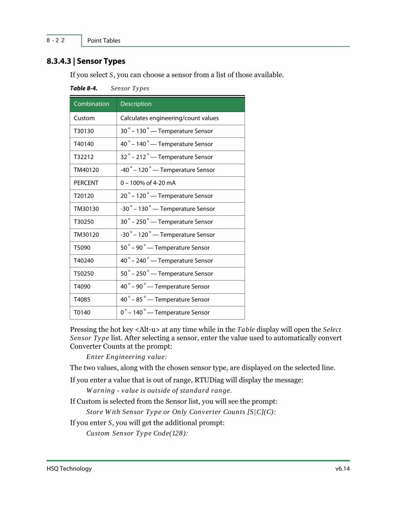
Point Tables8 - 2 2
HSQ Technology v6.14
8.3.4.3 | Sensor Types
If you select S, you can choose a sensor from a list of those available.
Pressing the hot key <Alt-u> at any time while in the Table display will open the Select Sensor Type list. After selecting a sensor, enter the value used to automatically convert Converter Counts at the prompt:
Enter Engineering value:The two values, along with the chosen sensor type, are displayed on the selected line.
If you enter a value that is out of range, RTUDiag will display the message:Warning - value is outside of standard range.
If Custom is selected from the Sensor list, you will see the prompt:Store With Sensor Type or Only Converter Counts [S|C](C):
If you enter S, you will get the additional prompt:Custom Sensor Type Code(128):
Table 8-4. Sensor Types
Combination Description
Custom Calculates engineering/count values
T30130 30 º – 130 º — Temperature Sensor
T40140 40 º – 140 º — Temperature Sensor
T32212 32 º – 212 º — Temperature Sensor
TM40120 -40 º – 120 º — Temperature Sensor
PERCENT 0 – 100% of 4-20 mA
T20120 20 º – 120 º — Temperature Sensor
TM30130 -30 º – 130 º — Temperature Sensor
T30250 30 º – 250 º — Temperature Sensor
TM30120 -30 º – 120 º — Temperature Sensor
T5090 50 º – 90 º — Temperature Sensor
T40240 40 º – 240 º — Temperature Sensor
T50250 50 º – 250 º — Temperature Sensor
T4090 40 º – 90 º — Temperature Sensor
T4085 40 º – 85 º — Temperature Sensor
T0140 0 º – 140 º — Temperature Sensor

v6.14 RTU Diagnostics User Manual
RTU Point Map 8 - 2 3
Custom Sensor Type Codes are only available from 128 to 255, Standard Sensors are assigned Type Codes from 1 to 127. This displays in the Values field along with the Converter Counts. Select the number of a predefined custom sensor type or create a new one. The remaining prompts are the same:
Enter engineering units low value(0):Enter engineering units high value(100):Enter converter count lo limit (819):Enter converter count hi limit (4095):
Enter the engineering low and high values and the converter count LO and HI limits. Be sure that the values correspond to the AI configuration and termination.

Point Map for Multiplexing PLC Points8 - 2 4
HSQ Technology v6.14
8.4 | Point Map for Multiplexing PLC Points
8.4.1 | Defining a PLC Board Type
To enable communication with a PLC, the RTU board type: PLC must be selected for one or all of the point types (AI, DI, DV, and AO). All file types in the PLC must be defined as an integer number (refer to Table 9-4 on page 9-23 for specific types). PLC Board Types are entered into the Point Map in the same way as other types of boards.
Each PLC Board Type has a table associated with it that defines how to map the points to the PLC address space. All RTU to PLC READ and WRITE functions are defined by the PLC Board Type definitions. All input type points are scanned on an interval depending on the configured amount of time (see “Configuration Parameters – Times” on page 6-11 for details). Each value is sent to the PLC at the next scheduled scan interval after the WRITE command is issued to the RTU.
8.4.2 | Building a PLC Table
In the Point Table, select the line with the PLC Board Type. Move the cursor to the PLC TABL column and press <Enter>. A secondary table opens that allows you to edit the Point table for the PLC. Each PLC table defines consecutive PLC registers that correspond to points. If there are breaks in the PLC register definition, a new PLC table definition is required. Refer to “Non-Contiguous Registers into Contiguous Points” on page 9-9 for more information. For more specific information, refer to “Creating a Modbus Point Map” on page 9-22.
FYI: The range of the PLC table points, first-to-last, must be within the range of the board definition, otherwise an error message is displayed.
For information on 32-bit COS reporting, refer to “32-Bit Modbus Value Processing” on page 9-15.
8.4.2.1 | Maximum Allowable Range
The PLC maximum allowable range is 114 integers for N-type files (as defined by the AI and DI points in any one PLC table entry).
The maximum allowable range for RTU AI type points is defined by the following equation:(Last Point − First Point) ≤ 114
The maximum allowable range for RTU DI type points is defined by the following equation:(Last Point – First Point)3 × 16 ≤ 1824

v6.14 RTU Diagnostics User Manual
RTU Point Map 8 - 2 5
In addition, a PLC table is not allowed to request undefined or out-of-range PLC registers. For example, a PLC table may not request registers N30:0 through N30:20 if the PLC file has previously been defined with N30 containing only ten registers.
8.4.2.2 | Analog PLC Point Mapping
Analog points map to the PLC registers in a one-to-one ratio. For example, an AI would map to the PLC as follows:
AI point 1 maps to PLC address N40:0AI point 2 maps to PLC address N40:1……AI point 16 maps to PLC address N40:15
Analog outputs are mapped in the same manner and executed on an AO WRITE request from the Host.
8.4.2.3 | Digital PLC Point Mapping
Each PLC register maps to sixteen digital points with the first digital point mapping to the Least Significant Bit (LSB) of the first PLC register. If more than sixteen digital points are defined, the next group of sixteen digital points will map in a similar manner to the next consecutive PLC register.
8.4.2.4 | Each Additional PLC Register
Overlapping PLC registers can be useful. For example, you can start and stop a set of digital outputs simultaneously by mapping the RTU DO points to RTU AO point types in the same PLC register address space or read a set of digital inputs using a single analog input READ.
Table 8-5. First PLC Register
MSB LSB
DI/DO+16 First DI/DO
Table 8-6. Each Additional PLC Register
First PLC Register PLC Register +1 PLC Register +n
MSB LSB MSB LSB MSB LSB
DI/DO+16 First DI/DO DI/DO+32 DI/DO+17 DI/DO+ DI/DO+…

Point Map for Multiplexing PLC Points8 - 2 6
HSQ Technology v6.14
8.4.3 | RTU Scanning Operation
When scanning the PLC, all of the input data is requested at every scan interval.
If there are no Start or Stop commands, all Digital Outputs (DO) are set to zero at each scan interval.
If a Start or Stop command is issued, then a logical 1 is set for that DO.
All output requests are processed at the next scheduled scan interval.
For each scan interval, inputs are read first, and then digital outputs are written, followed by writing any analog outputs.
If a Start command is issued for DV 1 and DI 1 is mapped to the same PLC address, the first scan interval reads a zero for DI 1 and then sets DV 1 to one. At the second scan interval, DI 1 is read as one and then DV 1 is set to zero. The third scan interval would then yield a zero for DI 1.
8.4.4 | Supported PLC Types
Subsequent to the release of Version 8 (v8) of the RTU software, support for more than one PLC type was enabled.
Construct V8 point map PLC point tables using the PLC types shown below. In all cases, the RTU is the Master and the PLC device is the slave.
Table 8-7. Supported PLC Types
PLC Board Type Number Description
SERIAL_MODBUS_MASTER 1 Serial Modbus
ETHERNET_SLC500_MASTER 2Ethernet Allen Bradley PCCC for SLC500 type
devices
ETHERNET_ENCIP_MASTER 3 Ethernet Industrial Protocol
ETHERNET_MODBUS_MASTER_ID255 4 Ethernet Modbus using Modbus ID 255
SERIAL_ASI 5 Serial ASI 8055/8255/8655/etc.
SERIAL_HSQ8_MASTER 6 Serial HSQ8
SERIAL_HSQ16_MASTER 7 Serial HSQ16
ETHERNET_HSQ_MASTER 8 Ethernet HSQ
ETHERNET_DNP_MASTER 9 Ethernet DNP Protocol
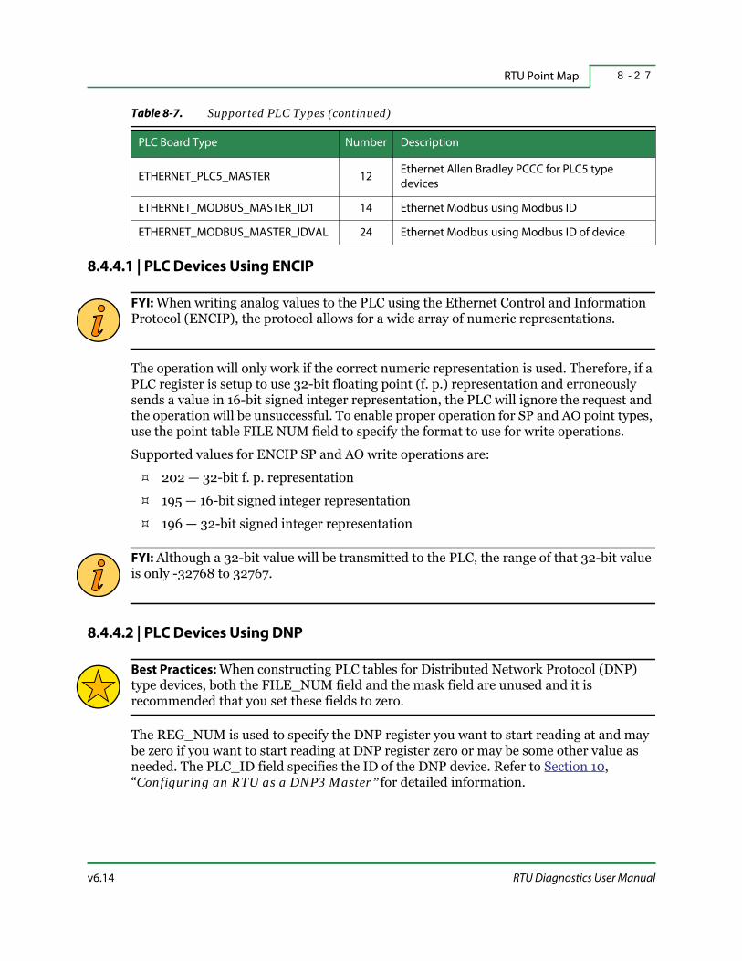
v6.14 RTU Diagnostics User Manual
RTU Point Map 8 - 2 7
8.4.4.1 | PLC Devices Using ENCIP
FYI: When writing analog values to the PLC using the Ethernet Control and Information Protocol (ENCIP), the protocol allows for a wide array of numeric representations.
The operation will only work if the correct numeric representation is used. Therefore, if a PLC register is setup to use 32-bit floating point (f. p.) representation and erroneously sends a value in 16-bit signed integer representation, the PLC will ignore the request and the operation will be unsuccessful. To enable proper operation for SP and AO point types, use the point table FILE NUM field to specify the format to use for write operations.
Supported values for ENCIP SP and AO write operations are:
202 — 32-bit f. p. representation
195 — 16-bit signed integer representation
196 — 32-bit signed integer representation
FYI: Although a 32-bit value will be transmitted to the PLC, the range of that 32-bit value is only -32768 to 32767.
8.4.4.2 | PLC Devices Using DNP
Best Practices: When constructing PLC tables for Distributed Network Protocol (DNP) type devices, both the FILE_NUM field and the mask field are unused and it is recommended that you set these fields to zero.
The REG_NUM is used to specify the DNP register you want to start reading at and may be zero if you want to start reading at DNP register zero or may be some other value as needed. The PLC_ID field specifies the ID of the DNP device. Refer to Section 10, “Configuring an RTU as a DNP3 Master” for detailed information.
ETHERNET_PLC5_MASTER 12Ethernet Allen Bradley PCCC for PLC5 type
devices
ETHERNET_MODBUS_MASTER_ID1 14 Ethernet Modbus using Modbus ID
ETHERNET_MODBUS_MASTER_IDVAL 24 Ethernet Modbus using Modbus ID of device
Table 8-7. Supported PLC Types (continued)
PLC Board Type Number Description

Point Map for Multiplexing PLC Points8 - 2 8
HSQ Technology v6.14
8.4.5 | PLC Error Messages
If the RTU receives an error message from the PLC, it will issue a MUX down COS message to the Host. The error code can then be read from custom DI point 31.
8.4.6 | Allen-Bradley PLC Definitions
To program the PLC, refer to the programming manuals published by Allen-Bradley.
Table 8-8. PLC Error Messages
Hex Value Description
00 Not used.
01 Error in converting block address.
02 Less levels specified in address then minimum for any address.
03 More levels specified in the address than the system supports.
04 Symbol not found.
05 Symbol is not the proper format.
06 Address does not point to anything usable.
07 File is wrong size.
08 Cannot complete request, situation has changed since start of the command.
09 File is too large.
0A Transaction size plus word address is too large.
0B Access denied, improper privilege.
0C Condition cannot be generated, resource not available. (There is active upload.)
0D Condition already exists, resource is already available.
0E Shutdown could not be executed.
0F Requester does not have upload or download access, no privilege.
10 Histogram overflow.
11 Illegal data type.
12 Bad parameter.
13 Address reference exists to deleted data table.
14 - FE Not used.
FF Communication link down.

9 - 1v6.14 RTU Diagnostics User Manual
S E C T I O N 9
CONFIGURING AN RTU AS
A MODBUS MASTER
Modbus is a communication protocol used to establish Master-Slave communications between industrial, electronic devices. The Master initiates communications and the Slave device replies. An HSQ RTU can act as a Modbus Master and poll Modbus Slave devices. This means the RTU serves as a gateway between Modbus devices and the MISER Host. Communication between the Master and the Slave is available via either serial or Ethernet or both. Registers on the Modbus devices are treated as Analog Inputs, Analog Outputs, Digital Inputs, and Device Points in special entries in the RTU Point Map called PLC Boards.
This section describes:
Introduction
How Data is Stored in Modbus
Supported Point Types, Registers, and Functions
Modbus Communications
PLC Table Entries and Modbus Registers
Reading Modbus Table Values into Points
RTU Mask Value
Writing Point Values to Modbus Table Entries
Creating a Modbus Point Map
Point Map Examples

Introduction9 - 2
HSQ Technology v6.14
9.1 | Introduction
When the RTU is operating as a Modbus Master it can address individual Slaves, which in turn respond to queries that are addressed specifically to them. A Modbus message sent from a Master to a Slave contains the address of the Slave, the “command” function code, the data, and the checksum. A response Modbus message from a Slave to the Master contains fields confirming the action taken, any data to be returned, and a checksum. If an error occurs or the Slave is unable to perform the requested action, the Slave constructs an error message and sends it as its response. See Appendix D, “Modbus Message Formats” for examples of the different message formats.
This section describes the theory behind and the steps required to configure an HSQ (25x86 or 6000) RTU to function as a Modbus Master. This information applies primarily to RTUs with software version 8 R01f or later. It may also pertain to versions 1_4, 1_5, and 1_6 but the full set of features may not be available and there will be some variances from the procedures described here.
Some knowledge of Modbus system architecture and table addressing is assumed. The website: http://www.modbus.org/ and particularly the document: http://www.modbus.org/docs/Modbus_Application_Protocol_V1_1b.pdf provide in-depth information on the subject.
In order to effectively use this information, you must understand how your Modbus Slave devices work and how they respond to commands. Please refer to the service manual for your particular devices.
FYI: Most importantly, confirm that the remote device supports the Modbus protocol.
Typically, an HSQ RTU is connected to one or more Modbus devices in order to perform simple tasks. However, it may perform more complex operations. In this section some headings are marked, “This is recommended for Technically Advanced Users only.” Beginners or those wanting only to perform simple operations can skip these descriptions.

v6.14 RTU Diagnostics User Manual
Configuring an RTU as a Modbus Master 9 - 3
9.2 | How Data is Stored in Modbus
Information is stored in the Slave device in four different tables. Two tables store ON/OFF discrete values (coils) and two store numerical values (registers). The coils and registers each have a read-only table and read-write table.
Each table has 9999 values. Each coil or contact is one bit and assigned a data address between 0000 and 270E (hexadecimal). Each register is one word (sixteen bits or two bytes) and also has a data address between 0000 and 270E in hexadecimal.
Coil/Register Numbers can be thought of as location names since they do not appear in the actual messages. The Data Addresses are used in the messages.
For example, the first Holding Register, number 40001, has the Data Address 0000. Each table has a different offset: 1, 10001, 30001, and 40001.
Table 9-1. Modbus Slave Tables
Table Name Type Data Addresses (hex) Coil/Register Numbers
Discrete Output Coils Read-Write 0000 to 270E 1-9999
Discrete Input Contacts Read-Only 0000 to270E 10001-19999
Analog Input Registers Read-Only 0000 to 270E 30001-39999
Analog Output Holding Registers Read-Write 0000 to 270E 40001-49999

Supported Point Types, Registers, and Functions9 - 4
HSQ Technology v6.14
9.3 | Supported Point Types, Registers, and Functions
The RTU Modbus Master software supports several point types and Modbus functions.
9.3.1 | Modbus Point Types
The RTU Modbus Master software supports these point types:
RTU Analog Input (AI) — initializes read transmissions to the Modbus Slave (only read commands are supported).
RTU Digital Input (DI) — initializes read transmissions to the Modbus Slave (only read commands are supported).
RTU Analog Output (AO) — initializes read and write transmissions to the Modbus Slave.
RTU Device Point (DV) — initializes read and write transmissions to the Modbus Slave.
9.3.2 | Modbus Registers
The Modbus standard specifies that a device can have tables made up of the following four types:
Discrete Inputs — Single bit, read-only.
Discrete Coils — Single bit, read/write.
Input Registers — 16-bit word, read-only.
Holding Registers — 16-bit word, read/write.
There are specific procedures for reading and writing values to and from these Modbus tables.
9.3.3 | Read Function Codes
For each Modbus table type, a specific Modbus Read Function Code value is used; this is a built-in part of the Modbus protocol. The function code used determines the Modbus table to be read. It is not required that you specify a Read Function Code, in which case you can use the value zero. Refer to “Reading Modbus Table Values into Points” on page 9-11 for a description of how to implement these codes.
The table below shows the simplest and most basic approach to mapping Modbus table values into RTU points:
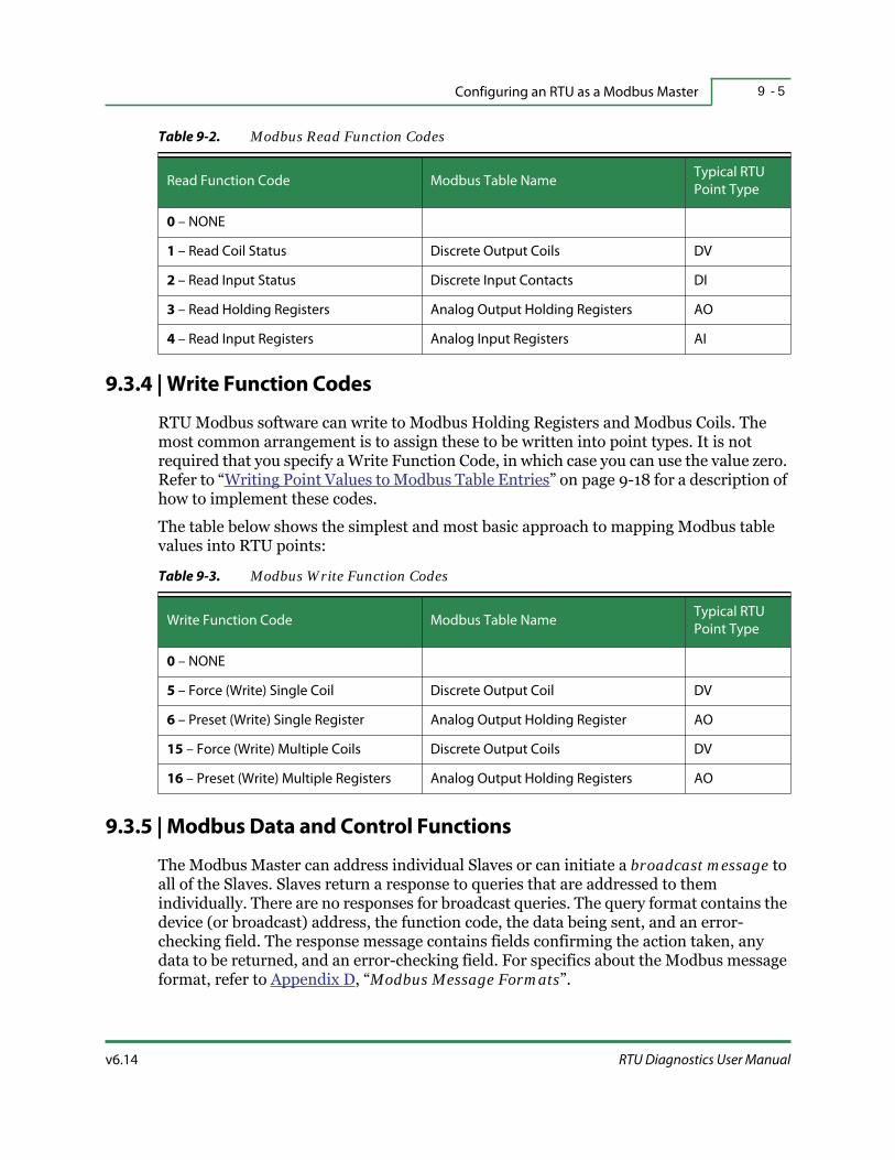
v6.14 RTU Diagnostics User Manual
Configuring an RTU as a Modbus Master 9 - 5
9.3.4 | Write Function Codes
RTU Modbus software can write to Modbus Holding Registers and Modbus Coils. The most common arrangement is to assign these to be written into point types. It is not required that you specify a Write Function Code, in which case you can use the value zero. Refer to “Writing Point Values to Modbus Table Entries” on page 9-18 for a description of how to implement these codes.
The table below shows the simplest and most basic approach to mapping Modbus table values into RTU points:
9.3.5 | Modbus Data and Control Functions
The Modbus Master can address individual Slaves or can initiate a broadcast message to all of the Slaves. Slaves return a response to queries that are addressed to them individually. There are no responses for broadcast queries. The query format contains the device (or broadcast) address, the function code, the data being sent, and an error-checking field. The response message contains fields confirming the action taken, any data to be returned, and an error-checking field. For specifics about the Modbus message format, refer to Appendix D, “Modbus Message Formats”.
Table 9-2. Modbus Read Function Codes
Read Function Code Modbus Table NameTypical RTU
Point Type
0 – NONE
1 – Read Coil Status Discrete Output Coils DV
2 – Read Input Status Discrete Input Contacts DI
3 – Read Holding Registers Analog Output Holding Registers AO
4 – Read Input Registers Analog Input Registers AI
Table 9-3. Modbus Write Function Codes
Write Function Code Modbus Table NameTypical RTU
Point Type
0 – NONE
5 – Force (Write) Single Coil Discrete Output Coil DV
6 – Preset (Write) Single Register Analog Output Holding Register AO
15 – Force (Write) Multiple Coils Discrete Output Coils DV
16 – Preset (Write) Multiple Registers Analog Output Holding Registers AO

Modbus Communications9 - 6
HSQ Technology v6.14
9.4 | Modbus Communications
9.4.1 | Modbus Master Operations Using Ethernet
When communicating over Ethernet, the RTU can poll the individual Modbus Slaves by knowing their IP addresses. You cannot connect two Modbus devices with the same IP address to the same RTU; the RTU will not be able to address them properly. The IP address and the corresponding Modbus ID, which is also the MUX ID for the MISER Host system, are defined using RTU Diagnostics via the RTU menu:
RTU… > RTU Hrdwr Cnfg… > Network… > Send RIO ConfigRefer to “Remote Input/Output Configuration” on page 6-22 for details.
Figure 9-1. Modbus Ethernet Communication Topology
Most Modbus devices receive Ethernet messages with the transmission ID field set to 255 (as specified in the Modbus standard), use a PLC TYPE value of 4 in the Point Map.
FYI: Some non-standard Modbus devices need to receive Ethernet messages with the transmission ID field set to 1, in this case use a PLC TYPE value of 14 in the Point Map. Other Ethernet Modbus devices need to have the transmission ID field set to the actual device ID, in those cases use a PLC TYPE value of 24. Refer to Table 9-4, “Modbus PLC Board Types,” on page 9-23 for details.
Modbus
Ethernet
Slave 1
Modbus
Ethernet
Slave 2
Modbus
Ethernet
Slave 3
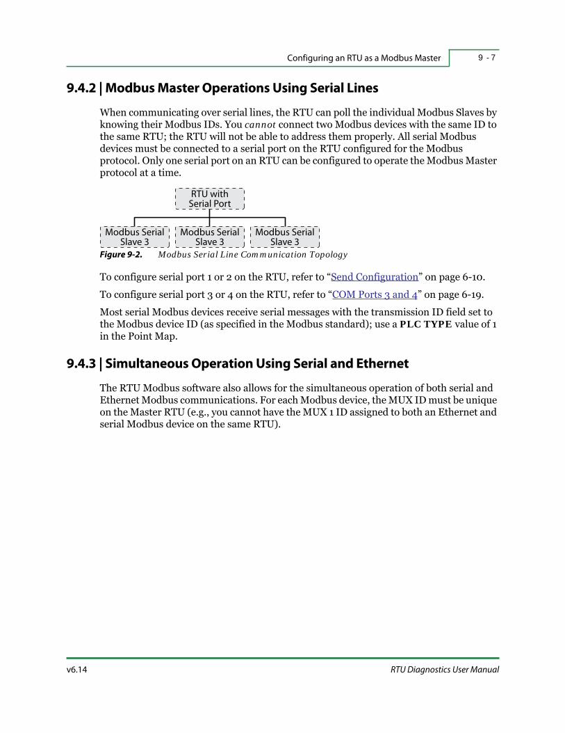
v6.14 RTU Diagnostics User Manual
Configuring an RTU as a Modbus Master 9 - 7
9.4.2 | Modbus Master Operations Using Serial Lines
When communicating over serial lines, the RTU can poll the individual Modbus Slaves by knowing their Modbus IDs. You cannot connect two Modbus devices with the same ID to the same RTU; the RTU will not be able to address them properly. All serial Modbus devices must be connected to a serial port on the RTU configured for the Modbus protocol. Only one serial port on an RTU can be configured to operate the Modbus Master protocol at a time.
Figure 9-2. Modbus Serial Line Communication Topology
To configure serial port 1 or 2 on the RTU, refer to “Send Configuration” on page 6-10.
To configure serial port 3 or 4 on the RTU, refer to “COM Ports 3 and 4” on page 6-19.
Most serial Modbus devices receive serial messages with the transmission ID field set to the Modbus device ID (as specified in the Modbus standard); use a PLC TYPE value of 1 in the Point Map.
9.4.3 | Simultaneous Operation Using Serial and Ethernet
The RTU Modbus software also allows for the simultaneous operation of both serial and Ethernet Modbus communications. For each Modbus device, the MUX ID must be unique on the Master RTU (e.g., you cannot have the MUX 1 ID assigned to both an Ethernet and serial Modbus device on the same RTU).
Modbus SerialSlave 3
RTU withSerial Port
Modbus SerialSlave 3
Modbus SerialSlave 3

PLC Table Entries and Modbus Registers9 - 8
HSQ Technology v6.14
9.5 | PLC Table Entries and Modbus Registers
The PLC Table is configured via the Point Map menu:RTU… > RTU Hrdwr Cnfg… > Point Map…
Refer to “Building an RTU Point Map” on page 8-4 for details.
9.5.1 | Contiguous Registers into Contiguous Points
It is often expedient to read a number of contiguous PLC registers into a contiguous set of points.
Figure 9-3. Reading Contiguous PLC Registers into Contiguous Points Diagram
Figure 9-4. Contiguous PLC Registers and Contiguous Points, Point Map Example
RTU Modbus Device
Holding Register 40100
Holding Register 40101
Holding Register 40102
Holding Register 40103
AI 10
AI 11
AI 12
AI 13

v6.14 RTU Diagnostics User Manual
Configuring an RTU as a Modbus Master 9 - 9
In the previous examples, the Modbus Holding Registers 40100-40103 are read into AI points 10-13. The Point Map line specifying AIs 10-13 and the single PLC Table entry specifying that AIs 10-13 correspond to Modbus Holding Registers starting at 40100. Below is a step-by-step setup for the example:
1. Set the PLC TYPE to 4, since this is an Ethernet PLC that expects the Transmission ID to be set to 255. Set the BIT CHECK to 0.
2. Set the FIRST PT to 10 and the LAST PT to 13.
3. Set the PLC ID to 1 since this is the RIO ID of the PLC.
4. For FILE NUM, set READ FUNCITON to 3 since Read Holding Register is the desired Modbus function. Set WRITE FUNCTION to 0 since the registers will not be written to (the purpose is to read into RTU AIs).
5. Set the REG NUM to 100 since the first Modbus register to read is 40100.
6. For TYPE MASK, set TYPE to 255 and MASK to 255.
See “Creating a Modbus Point Map” on page 9-22 for details on all the entries.
9.5.2 | Non-Contiguous Registers into Contiguous Points
Sometimes it is desirable to read a number of non-contiguous PLC registers into a contiguous set of points.
Figure 9-5. Reading Non-Contiguous PLC Registers into Contiguous Points Diagram
RTU Modbus Device
Holding Register 40100
Holding Register 40101
Holding Register 40110
Holding Register 40111
AI 10
AI 11
AI 12
AI 13

HSQ Technology v6.14
PLC Table Entries and Modbus Registers9 - 1 0
Figure 9-6. Non-Contiguous PLC registers and Contiguous Points, Point Map Example
In the above examples, the Modbus Holding Registers 40100-40101 are read into AI points 10-11 and Modbus Holding Registers 40110-40111 into AI points 12-13. Notice the Point Map line specifying AIs 10-13 and the two PLC Table entries specifying that AIs 10-11 correspond to Modbus Holding Registers starting at 40100 and that AIs 12-13 correspond to Modbus Holding Registers starting at 40110.

v6.14 RTU Diagnostics User Manual
Configuring an RTU as a Modbus Master 9 - 1 1
9.6 | Reading Modbus Table Values into Points
The RTU Modbus software can read four types of Modbus table entries. The most common arrangement is to assign these to be read into RTU point types. Refer to Table 9-2, “Modbus Read Function Codes,” on page 9-5 for details.
Generally, the data value read from any of these four Modbus types can be deposited into any DI, DV, AI, or AO points. Whatever value is read from the Modbus tables is first converted to a 16-bit value. This 16-bit value is then deposited into the specified point type. This approach allows for a high level of flexibility in processing Modbus table values. This process is diagrammed below for the “Discrete Input” type, but can also apply to “Coil”, “Input Register”, and “Holding Register” types.
Figure 9-7. Modbus Table Values Diagram
RTU Modbus logic allows a single Point Map entry to read multiple Modbus table values and deposit the results into multiple points.
FYI: RTU software prior to and including version R03b, is limited to a maximum of fifteen points per Point Map entry.
9.6.1 | Modbus Handling of Read Errors
You can read an entire range of Modbus table entries into a corresponding range of RTU points using a single PLC Table entry. There is a maximum of 125 16-bit registers available when this is done. This results in the RTU sending a single read request that specifies a range of Modbus registers to be read as a single operation. If this range of
RTU Modbus Device
Discrete Input
Coil
Input Register
Holding Register
DI
DV
AI
SP
AO

Reading Modbus Table Values into Points9 - 1 2
HSQ Technology v6.14
Modbus registers includes one or more Modbus register numbers that do not exist in the Modbus device, then the entire read request will be rejected by the Modbus device (as specified in the Modbus protocol standards).
If you are having trouble getting a Modbus read operation to work, verify that the range of Modbus registers is complete and accurate. One simple way to check for this is to reduce the register range down to a single register. If things start working, that suggests you might be attempting to read a non-existent Modbus register from the device.
Error codes are explained in “Exception Responses (Error Codes)” on page D-10.
9.6.2 | Using Modbus Read Function Code 1 and 2
Modbus Read Function Code 1 (Read Coil Status) and 2 (Read Input Status) are both used to read binary values from the Modbus data tables. The resulting value deposited into a point will always be restricted to the values of 0 or 1. These Read Function Codes are most commonly used for DI and DV point values. The RTU Modbus code logic allows these Read Function Codes to deposit values into any of the basic point types (DI, AI, DV, and AO).
9.6.2.1 | Calculating the Resulting Value
The RTU Modbus logic will take the binary value read from the Modbus Slave device and deposit the result (0 or 1) into the specified point.
9.6.3 | Using Modbus Read Function Code 3 and 4
Modbus Read Function Code 3 (Read Holding Registers) and 4 (Read Input Registers) are both used to read 16-bit analog values from the Modbus data tables. While these Read Function Codes are most commonly used for AO and AI point values, the RTU Modbus code logic allows these Read Function Codes to deposit values into any of the basic point types (DI, AI, DV, and AO). When you use Modbus Read Function Code 3 or 4, the value of the TYPE and MASK fields should normally be 255. For exceptions to this rule, refer to “32-Bit Modbus Value Processing” on page 9-15.
9.6.3.1 | Calculating the Resulting Value for AI and AO Points
The RTU Modbus logic takes the 16-bit binary value read from the Modbus Slave device and directly deposits the result into the specified point. RTU logic will always interpret analog points as being 16-bit signed values. Therefore, if the Modbus device provides a 16-bit unsigned value, other portions of the RTU code (COS, generation logic, VCL, control blocks, etc.) will need special logic to handle values greater than 32767.
9.6.3.2 | Calculating the Resulting Value for DI and DV Points
The RTU Modbus logic sets the value for DI and DV points to zero or one and uses the additional field known as bit-check. The bit-check field is expected to have a value in the

v6.14 RTU Diagnostics User Manual
Configuring an RTU as a Modbus Master 9 - 1 3
range of zero to fifteen. The RTU Modbus logic will take the 16-bit binary value read from the Modbus Slave device and will retain only the bit specified by bit-check. The resulting value of zero or one will be directly deposited, as the result, into the specified point. Setting bit-check to a value outside the range of zero to fifteen is meaningless and will produce undefined results.
9.6.4 | Host COS Considerations
Older MISER host computers are incapable of handling RTU COS transmissions involving AO point types. Furthermore, RTU software versions prior to R03d did not support AO COS processing at all and AO COS processing logic was not very robust in RTU software versions prior to R03h. For this reason, operators of older systems might want to avoid reading Modbus values into AO points.

RTU Mask Value9 - 1 4
HSQ Technology v6.14
9.7 | RTU Mask Value
9.7.1 | Using All Bits Read from the Modbus Device
The MASK value is used to specify which of the bits read from the Modbus device should be used and which should be ignored. Typically, you will want to use all the bits read from the Modbus device, in this case the MASK and TYPE values should be set to 255. If all the bits read from the Modbus Slave device are used and none are ignored, the values are simply extracted and used for the logic. For example, a Point Map entry to read sixteen points, starting from Modbus register 10, would then deposit the sixteen values from registers 10 through 25 into the points.
9.7.2 | Using Only Some of the Bits Read from the Modbus Device
This is recommended for Technically Advanced Users only.
By specifying a TYPE and MASK value other than 255, it is possible to use only some of the bits read from the Modbus device and ignore the rest. In this process, the TYPE and MASK fields are combined to form a single 16-bit value (TYPE is the HI byte, MASK is the LO byte). Any bit position set to 1 in the resulting 16-bit value will correspond to a Modbus bit to be used and any bit position set to 0 will be skipped. Since this is a 16-bit field, the operations are always done in groupings of sixteen bits.
Figure 9-8. Selective Bit Reading Diagram
In the above example, a Point Map entry reads the four DI points numbered 1-4, starting from Modbus register 10 using a TYPE value of 0 and a MASK value of 3. The two values from the Modbus Discrete Input registers 10 and 11 are deposited into DI points 1 and 2.
RTU Modbus Device
Discrete Input 10010
Discrete Input 10011
Discrete Input 10026
Discrete Input 10027
DI 1
DI 2
DI 3
DI 4

v6.14 RTU Diagnostics User Manual
Configuring an RTU as a Modbus Master 9 - 1 5
The next fourteen Modbus registers are skipped and then the two values from the Modbus Discrete Input registers, 26 and 27, are deposited into the next two DI points, 3 and 4.
9.7.3 | 32-Bit Modbus Value Processing
The information below describes how to send 32-bit COS information from a PLC to the MISER Host.
Warning: The RTU must have software version v8r03u or higher and the MISER Host must have the latest version of CSPROC (update to v6.13). Also, the RTU or PLC must have 32-bit points.
9.7.3.1 | 32-Bit Modbus Integer COS Points
This is recommended for Technically Advanced Users only.
The RTU Modbus logic has a special provision for handling Modbus 16-bit register pairs as a unified value, providing a 32-bit result. The resulting 32-bit value is then provided to the Host via an equivalent pair of 16-bit points. To use this feature, you must adhere to the following conditions:
The PLC point table entry must allow for two Modbus registers.
The Modbus Read Function Code 3 (Read Holding Register) or 4 (Read Input Register) must be used to read the pair of Modbus registers.
The point type must be AI or AO. If the point type is AO, then there is the further requirement that the WRITE FUNCTION field must be zero.
Each 32-bit must be comprised of two consecutive points.
The TYPE field must be set to 0 and the MASK field must be set to 4. This alerts the RTU that these points need to be treated as a 32-bit integer value.
Figure 9-9. 32-Bit Modbus Integer Point Entry, Point Map Example

RTU Mask Value9 - 1 6
HSQ Technology v6.14
If each of the above conditions is met, then the points are handled as 32-bit register pairs and the following special processing rules apply:
The lower numbered Modbus register will normally contain the more significant sixteen bits and the next higher numbered Modbus register will contain the less significant sixteen bits. (This is so the Host software will know how to reassemble the two points into a single unified 32-bit value.)
Any COS tolerance specified in the point definitions will be disregarded for these points; instead, any non-zero change on either of the points will trigger COS processing. This COS processing will generate a pair of COS packets corresponding to the two points in the register pair. Both COS packets will have identical time stamps.
If either of the two points involved in a register pair is disabled, then both are treated as being disabled by the COS processing logic.
9.7.3.2 | 32-Bit Modbus Floating Point COS Points
This is recommended for Technically Advanced Users only.
This configuration sends 32-bit COS information from the Modbus device to the MISER Host. To use this feature, you must comply with the following conditions:
The PLC point table entry must allow for two Modbus registers.
The Modbus Read Function Code 3 (Read Holding Registers) or 4 (Read Input Register) must be used to read the pair of Modbus registers.
The point type must be AI or AO. If the point type is AO, then there is the further requirement that the WRITE FUNCTION field must be 0.
Each 32-bit register must be comprised of two consecutive points.
The TYPE field must be set to 0 and the MASK field must be set to 5. This alerts the RTU that these points need to be treated as a 32-bit floating point value.
Figure 9-10. 32-Bit Modbus Floating Point Entry, Point Map Example

v6.14 RTU Diagnostics User Manual
Configuring an RTU as a Modbus Master 9 - 1 7
If each of the above conditions is met, then the points are handled as 32-bit register pairs and the following special processing rules apply:
The lower numbered Modbus register will normally contain the most significant sixteen bits and the next higher numbered Modbus register will contain the least significant sixteen bits. (This is so the Host software will know how to reassemble the two points into a single unified 32-bit value.)
Any COS tolerance specified in the point definitions will be disregarded for these points; instead, any non-zero change on either of the points will trigger COS processing. This COS processing will generate a pair of COS packets corresponding to the two points in the register pair. Both COS packets will have identical time stamps.
If either of the two points involved in a register pair is disabled, then both are treated as being disabled by the COS processing logic.
Related Docs: For information on properly defining these points on the MISER Host, refer to MISER System Manual, Analog Input Configurations.

Writing Point Values to Modbus Table Entries9 - 1 8
HSQ Technology v6.14
9.8 | Writing Point Values to Modbus Table Entries
The basic association of point values to the Modbus table entries being written is done the same way as “Contiguous Registers into Contiguous Points” on page 9-8 and “Non-Contiguous Registers into Contiguous Points” on page 9-9. To write the values to the Modbus table entries you need to specify the appropriate values for the WRITE FUNCTION field.
Figure 9-11. Writing Points into Modbus Table Entries Diagram
Figure 9-12. Writing Points into Modbus Table Entries, Point Map Example
For each Modbus table type, a set of specific Modbus Write Function Code values must be used. This is a built-in part of the Modbus protocol and the function code used determines the Modbus table to be written. Refer to the Table 9-3, “Modbus Write Function Codes,” on page 9-5 for details. Also, see “Creating a Modbus Point Map” on page 9-22 for details on all the entries.
RTU
SP 10
SP 11
SP 12
SP 13
Modbus Device
Holding Register 40100
Holding Register 40101
Holding Register 40102
Holding Register 40103

v6.14 RTU Diagnostics User Manual
Configuring an RTU as a Modbus Master 9 - 1 9
Generally, the data value from the point types DV and AO can be deposited into Modbus Coils or Holding Registers. Whatever value is obtained from the points is first converted to a 16-bit value.
Figure 9-13. Writing Points into Modbus Table Entries Diagram
This 16-bit value is then deposited into the specified Modbus table entry. This approach allows for a high level of flexibility in processing Modbus table values. The process diagrammed shows a DV type, but it can also apply to an AO type.
9.8.1 | Using Modbus Write Function Code 5 and 15
Modbus Write Function Code 5 (Write Single Coil) and 15 (Write Multiple Coils) are both used to write binary values to Modbus Coils. While these Write Function Codes are most commonly used for DV point values, the RTU Modbus code logic allows these Write Function Codes to deposit values from any of the basic point types (DV and AO). The value of the TYPE and MASK fields should normally be 255. When using the point type DV, the value is simply deposited into the specified Modbus Coil. When using an AO point type, then the specified Modbus Coil is set as follows:
The specified Modbus Coil is set to 0 if the AO point value was zero.
The specified Modbus Coil is set to 1 if the AO point value was non-zero.
9.8.2 | Single and Multiple Modbus Commands
The Modbus protocol allows Coils to be written with either the Write Single Coil (Function Code 5) or the Write Multiple Coils (Function Code 15) command. It also allows Modbus Holding Registers to be written with either the Write Single Register (Function Code 6) or the Write Multiple Registers (Function Code 16) command. The RTU Modbus Master logic supports both types of command codes.
Some Modbus devices support only Single… commands or only Multiple… commands. In these cases, you should use the write command codes supported by your device. In cases where the Modbus device supports both Single… and Multiple… commands, you can use either one. There is no noticeable gain in efficiency resulting from using one or the other.
RTU Modbus Device
Coil
Holding Register
DV
SP
AO

Writing Point Values to Modbus Table Entries9 - 2 0
HSQ Technology v6.14
9.8.3 | Using Modbus Write Function Code 6 and 16
Modbus Write Function Code 6 (Write Single Register) and 16 (Write Multiple Registers) are both used to write 16-bit analog values to the Modbus Holding Registers. While these Write Function Codes are most commonly used for AO point values, the RTU Modbus code logic allows these Write Function Codes to deposit values from any of the basic point types (DV and AO). When using an AO point type, the value of the TYPE and MASK fields should normally be 255.
9.8.3.1 | Using Modbus Write Function Code 6 and 16 with DV Points
This is recommended for Technically Advanced Users only.
When using the DV point type, the values specified in the READ FUNCTION, TYPE, and MASK fields are used as follows:
If READ FUNCTION is set to zero:
When the DV is ON, the value of the Holding Register is set to the result of: (BIT CHECK × 256) + TYPE.
When the DV is OFF, the value of the Holding Register is set to the value in MASK.
If READ FUNCTION is set to a non-zero value:
When the DV is ON, the value of the Holding Register is set to the value in TYPE.
When the DV is OFF, the value of the Holding Register is set to the value in MASK.
FYI: BIT CHECK, TYPE, and MASK are 8-bit fields.

v6.14 RTU Diagnostics User Manual
Configuring an RTU as a Modbus Master 9 - 2 1
9.8.4 | Using Modbus Command 22
This is recommended for Technically Advanced Users only.
Modbus Write Function Code 22 (Mask Write Register) can be used if you want to set a single bit within a Modbus Holding Register to 1 whenever the DV is on and to set that same single bit to 0 when the DV is off. In each of these cases, only one bit within the 16-bit Modbus Holding Register is operated on, the other fifteen bits are left unchanged.
The Modbus device must support Modbus command 22; not all Modbus devices support this feature. Check the documentation for your device.
Figure 9-14. Configuring Modbus Command 22, Point Map Example
To use Mask Register Write operations, set the PLC table entries as follows:
Set READ FUNCTION to 0.
Set WRITE FUNCTION to 22.
Set the STR field to 0.
Set the STP field to the value corresponding to the bit to be operated, this should be in the range 0 to 15.
Creating a Modbus Point Map9 - 2 2
HSQ Technology v6.14
9.9 | Creating a Modbus Point Map
Each Modbus table defines consecutive Modbus registers that correspond to RTU points. If there is a break in the Modbus registers definition, a new PLC table entry is required. For more information on creating Point Maps, refer to “Building an RTU Point Map” on page 8-4.
FYI: The range of points, first-to-last, must be within the range of the board definition (in the Point Map). Each point number in the table represents one register number in the Modbus Slave device.
How the RTU addresses registers in the Modbus Slave is not the same as points identified in the MISER Host database. For example, the MISER database point number 96 could be assigned to the Modbus Holding Register 40000 (where the first ninety-five AO points are already configured in the Point Map).
9.9.1 | Creating a PLC Board Type
1. From the Command Menu, select RTU… > RTU Hrdwr Cnfg… > Point Map….
If you already have a Point Map file, select Load Point Map from File and enter the file name without the extension. Otherwise, select Load Default Point Map.
2. To easily add the next consecutive PLC, find the largest LAST PT number from all of the PLC entries.
3. Move the cursor to that line and press <Insert> to create the next line with the same PT TYPE (point type). The 1st PT of the new line will be one more than LAST PT of the previous line. The number of points will be the same.
4. Press <Return> to edit the new line.
5. In the Edit window, change PT TYPE to the desired point type (DI, AI, DV, or AO).
6. Change the BD TYPE (board type) to PLC.
7. Move the cursor to PLC TABL and press <Return>. This creates a blank PLC Table Field.
8. Pressing <Insert> fills in default values. Press <Return> to edit these values.

v6.14 RTU Diagnostics User Manual
Configuring an RTU as a Modbus Master 9 - 2 3
Figure 9-15. Sample PLC Table Entry
9.9.1.1 | PLC Table Field Entries
Each of the data prompts used in the Modbus PLC Table entry are described below.
PLC TYPE — use the following values:
The PLC TYPE is dependent on the Modbus Slave device; refer to the manufacturer’s documentation.
BIT CHECK — this field appears after you enter a PLC TYPE for a Modbus device. Normally this field should be set to zero, unless all of the following conditions are true:
The PLC table entry specifies a FILE NUM of 3 (Read Holding Registers) or 4 (Read Input Register).
The Point Map entry is for a DI or DV type point.
You wish to read only a specific bit.
If all of the conditions are true, then the BIT CHECK field specifies which of the sixteen bits read from the Modbus device determine the point value. The value of the BIT CHECK field should be in the range of 0-15. BIT CHECK field values outside this range are meaningless.
Table 9-4. Modbus PLC Board Types
PLC Board Type Number Description
Serial Modbus Master 1 Serial Modbus
Ethernet Modbus Master ID 255 (typical) 4 Ethernet Modbus using Modbus ID 255
Ethernet Modbus Master ID 1 14 Ethernet Modbus using Modbus ID 1
Ethernet Modbus Master 24Ethernet Modbus using the actual
device ID.

Creating a Modbus Point Map9 - 2 4
HSQ Technology v6.14
FYI: Sometimes the displayed PLC TYPE field will be an expected number. In fact, this 16-bit field is used to hold two 8-bit subfields: PLC TYPE and BIT CHECK. Specifically, the value displayed is determined by the formula:[actual PLC TYPE] + (256 × [BIT CHECK]) = PLC TYPE.
1st PT — specifies the first point in a range of points that are governed by the PLC table entry. This value must be within the range specified by the corresponding Point Map entry.
LAST PT — specifies the last point in a range of points that are governed by the PLC table entry. In cases where a PLC table entry only governs a single point, you should set this to the same value as the FIRST PT field. This value must be within the range specified by the corresponding Point Map entry.
PLC ID — specifies the MUX ID used to identify this Modbus device to the RTU and the MISER Host system. For Modbus Serial Master operation, this is also the same as the Modbus device ID as set in the configuration of the Modbus device. For Modbus Ethernet Master operation, this must be the same as the RIO ID.
FILE NUM — this field prompts you to enter values for two functions:
READ FUNCTION — specifies the Modbus Read Function Code value used in Modbus poll operations and determines the Modbus table type to be read. See “Reading Modbus Table Values into Points” on page 9-11 for more details. If there is no need to read this register (e.g., if the register will only be written and never read) it is acceptable to use the value zero. Refer to “Read Function Codes” on page 9-4 for more information.
WRITE FUNCTION — specifies the Modbus Write Function Code value used in Modbus operations and it determines the Modbus table type to be written. See “Writing Point Values to Modbus Table Entries” on page 9-18 for more details. If there is no need to write to this register (e.g., if the register will only be read and never written to) it is acceptable to use the value zero. Refer to “Write Function Codes” on page 9-5 for more information.
FYI: Sometimes the displayed FILE NUM field will be an unexpected number. In fact, this 16-bit field is used to hold two 8-bit subfields: READ FUNCTION and WRITE FUNCTION. Specifically, the value displayed is determined by the formula: [READ FUNCTION] + (256 × [WRITE FUNCTION]) = FILE NUM.
REG NUM — specifies the Modbus register number to operate on. The starting register number is defined in the Modbus Slave device. The REG NUM is used in conjunction with FILE NUM to specify the actual memory address. For example, to read the first input register (30000) the FILE NUM Read Function needs to be set to 4 and the REG NUM set to 0.

v6.14 RTU Diagnostics User Manual
Configuring an RTU as a Modbus Master 9 - 2 5
FYI: RTU points start at one, but Modbus table entries start at zero. It is perfectly acceptable to specify a PLC Table entry REG NUM value of zero.
TYPE and MASK — these fields are used for storage of values specific to certain operations. Except in very special cases, these fields should be set to 255 (read all bits). In the case of DV points, these fields are displayed as STR and STP respectively.
When using Modbus Read Function Code 1 (Read Coils) or 2 (Read Discrete Inputs), the TYPE and MASK field are used to specify which of the sixteen bits read from the Modbus device are to be used and which are to be discarded. The TYPE field is the HI byte and the MASK field is the LO byte in this process. See “Using Modbus Read Function Code 1 and 2” on page 9-12 for more information.
When processing Modbus register pairs as 32-bit values, the TYPE filed must be 0 and the MASK field must be 4. See “32-Bit Modbus Value Processing” on page 9-15 for more details.
When using DV points to set the values of Modbus Holding Registers, the STR and STP fields form a part of the resulting value deposited into the holding register. See “Using Modbus Write Function Code 6 and 16 with DV Points” on page 9-20 for more details.
When using Modbus command 22 (Mask Write Register) the MASK field specifies the bit to be operated upon. See “Using Modbus Command 22” on page 9-21 for more details.
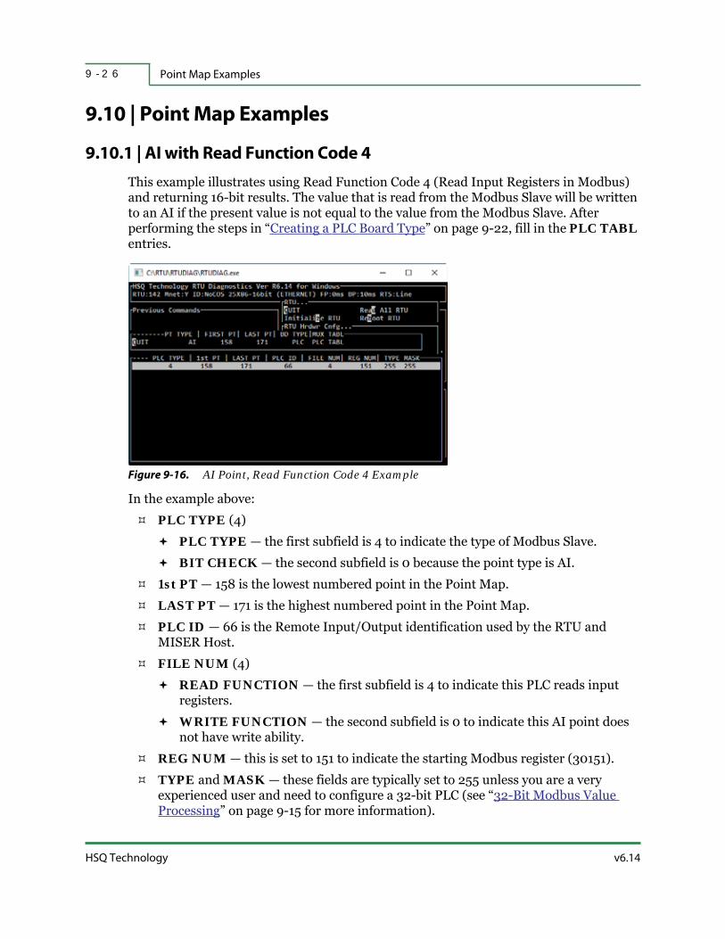
Point Map Examples9 - 2 6
HSQ Technology v6.14
9.10 | Point Map Examples
9.10.1 | AI with Read Function Code 4
This example illustrates using Read Function Code 4 (Read Input Registers in Modbus) and returning 16-bit results. The value that is read from the Modbus Slave will be written to an AI if the present value is not equal to the value from the Modbus Slave. After performing the steps in “Creating a PLC Board Type” on page 9-22, fill in the PLC TABL entries.
Figure 9-16. AI Point, Read Function Code 4 Example
In the example above:
PLC TYPE (4)
PLC TYPE — the first subfield is 4 to indicate the type of Modbus Slave.
BIT CHECK — the second subfield is 0 because the point type is AI.
1st PT — 158 is the lowest numbered point in the Point Map.
LAST PT — 171 is the highest numbered point in the Point Map.
PLC ID — 66 is the Remote Input/Output identification used by the RTU and MISER Host.
FILE NUM (4)
READ FUNCTION — the first subfield is 4 to indicate this PLC reads input registers.
WRITE FUNCTION — the second subfield is 0 to indicate this AI point does not have write ability.
REG NUM — this is set to 151 to indicate the starting Modbus register (30151).
TYPE and MASK — these fields are typically set to 255 unless you are a very experienced user and need to configure a 32-bit PLC (see “32-Bit Modbus Value Processing” on page 9-15 for more information).

v6.14 RTU Diagnostics User Manual
Configuring an RTU as a Modbus Master 9 - 2 7
9.10.2 | DI with Read Function Code 2
This example illustrates using Read Function Code 2 (Read Input Status) to read five specific bits of the 16-bit PLC. After performing the steps in “Creating a PLC Board Type” on page 9-22, fill in the PLC TABL entries.
Figure 9-17. DI Point, Read Function Code 2, Bits 5-9 Example
In the example above:
PLC TYPE (1294)
PLC TYPE — the first subfield is 14 to indicate the type of Modbus Slave.
BIT CHECK — the second subfield is 5 to indicate the individual bit to be read.
PLC TYPE (1550)
PLC TYPE — the first subfield is 14 to indicate the type of Modbus Slave.
BIT CHECK — the second subfield is 6 to indicate the individual bit to be read.
PLC TYPE (1806)
PLC TYPE — the first subfield is 14 to indicate the type of Modbus Slave.
BIT CHECK — the second subfield is 7 to indicate the individual bit to be read.
PLC TYPE (2062)
PLC TYPE — the first subfield is 14 to indicate the type of Modbus Slave.
BIT CHECK — the second subfield is 8 to indicate the individual bit to be read.
PLC TYPE (2318)
PLC TYPE — the first subfield is 14 to indicate the type of Modbus Slave.
BIT CHECK — the second subfield is 9 to indicate the individual bit to be read.
1st PT — 125, 126, 127, 128, and 129 are the points in the Point Map associated with the individual bits (5, 6, 7, 8, and 9 respectively) of the Modbus register.

Point Map Examples9 - 2 8
HSQ Technology v6.14
LAST PT — these are the same since the intent is to read specific bits.
PLC ID — 61 is the Remote Input/Output identification used by the RTU and MISER Host.
FILE NUM (2)
READ FUNCTION — the first subfield is 2 to indicate this PLC reads input status.
WRITE FUNCTION — the second subfield is 0 to indicate this DI point does not have write ability.
REG NUM — this is 61 to indicate the Modbus register (10061).
TYPE and MASK— these are set to 255 to indicate all the bits read from the Modbus Slave device are used, as is typical.
9.10.3 | AO with Read Function Code 3 and Write Function Code 16
This example illustrates using Read Function Code 3 (Read Holding Register) and Write Function Code 16 (Write Single Coil). This reads values from analog points and writes values to the same points depending on the point logic. After performing the steps in “Creating a PLC Board Type” on page 9-22, fill in the PLC TABL entries.
Figure 9-18. AO Point, Read Function Code 3 and Write Function Code 16 Example
In the example above:
PLC TYPE (1)
PLC TYPE — the first subfield is 1 to indicate the type of Modbus Slave.
BIT CHECK — the second subfield is 0 in order to read and write all 16-bits of the PLC.
1st PT — 96 is the first numbered point in the Point Map being read and written to.

v6.14 RTU Diagnostics User Manual
Configuring an RTU as a Modbus Master 9 - 2 9
LAST PT — 112 is the last numbered point in the Point Map being read and written to.
PLC ID — 51 is the Remote Input/Output identification used by the RTU and MISER Host.
FILE NUM (4099)
READ FUNCTION — the first subfield is 3 to indicate this PLC reads holding registers.
WRITE FUNCTION — the second subfield is set to 16 to indicate this PLC presets multiple registers.
REG NUM — this is set to 44 to indicate the starting Modbus register.
TYPE and MASK — these are set to 255, as is typical.
9.10.4 | DV with Write Function Code 6
This example illustrates using Write Function Code 6 (Preset Single Register). This sets a Modbus register to 1 when the DV is ON and the same register to 0 when the DV is OFF. After performing the steps in “Creating a PLC Board Type” on page 9-22, fill in the PLC TABL entries.
Figure 9-19. DV Point, Write Function Code 6 Example
In the example above:
PLC TYPE (4)
PLC TYPE — the first subfield is 4 to indicate the type of Modbus Slave.
BIT CHECK — the second subfield is 0 to specify all the bits of the Modbus register.
1st PT — 101 is the numbered point in the Point Map being written to.
LAST PT — this is the same point since the intent is to preset a single register.

Point Map Examples9 - 3 0
HSQ Technology v6.14
PLC ID — 76 is the Remote Input/Output identification used by the RTU and MISER Host.
FILE NUM (1536)
READ FUNCTION — the first subfield is 0 to indicate this DV point does not have read ability.
WRITE FUNCTION — the second subfield is 6 to indicate this PLC writes to a single register.
REG NUM — this is 1 to indicate the starting register.
STR and STP — 1 is the “VALUE FOR START” and 0 is the “VALUE FOR STOP”.

1 0 - 1v6.14 RTU Diagnostics User Manual
S E C T I O N 1 0
CONFIGURING AN RTU AS
A DNP3 MASTER
The Distributed Network Protocol Version 3.0 (DNP3) Master implements the client side of DNP3 and is a software component of the HSQ RTU software.
DNP3 is a protocol that defines the communication between industrial electronic devices by adhering to the client server model. The Master initiates communications and the Slave device replies. An HSQ RTU can be configured to act as a DNP3 Master and query DNP3 Slave devices. This means the RTU serves as a gateway between DNP3 devices and the MISER Host.
This section describes:
Overview
DNP3 Protocol Description
Configuration of the DNP3 Master

Overview1 0 - 2
HSQ Technology v6.14
10.1 | Overview
A DNP3 Master, running on an RTU, periodically sends requests to a DNP3 Slave that runs on a remote DNP3 unit. The DNP3 Slave responds with point information (e.g., value, status, timestamp, etc.) that is received by the DNP3 Master and stored inside the RTU. Thereafter, the Host receives the point information via the HSQ Change-of-State (COS) reporting mechanism. In this scenario, the RTU is normally called the DNP3 Primary unit and remote DNP3 unit is called the DNP3 Secondary unit. The RTU serves as the gateway between the MISER Host and DNP3 devices. The Master side of DNP3 is currently available over an Ethernet connection.
10.1.1 | Data Organization
With DNP3 there are two types of data pertaining to points: static and event data. Static data refers to the current value at the time when an input is accessed for reading. Event data refers to changes of an input (i.e., change-of-state, change-of-value, transient data, etc.) that can take place at any time. Event data can be reported with or without timestamps.
The protocol allows points to be associated with classes, which are defined inside the DNP3 Secondary unit by the user during the initial configuration phase. There are four classes supported, Class 0, Class 1, Class 2, and Class 3. Static data is associated with Class 0, while event data is associated to Classes 1, 2, and 3. The initial intention was for Class 1 events to have a higher priority and Class 3 events a lower priority, but this scheme has not been maintained by all DNP3 users. Separating points into classes allows for efficient read access to points and for a possible structured grouping of points.
Classes 1, 2, and 3 are integrated; a point can belong to more than one class or even to all three classes. The protocol allows for any combination of classes 1, 2, and 3; however, only Class 123 is currently supported. Class 123 contains all event data that belongs to Class 1, Class 2, and Class 3. Refer to “DNP3 Protocol Description” on page 10-7 for more information.
General knowledge of DNP3 is assumed. The website: https://www.dnp.org/ provides information on this subject.
In order to effectively use this information, you must understand how your DNP3 Slave devices work and how they respond to commands. Please refer to the service manual for your particular devices.
FYI: Most importantly, confirm that the remote device supports the DNP3 protocol.

v6.14 RTU Diagnostics User Manual
Configuring an RTU as a DNP3 Master 1 0 - 3
10.1.2 | Class Requests
The DNP3 Master needs to send a request to a DNP3 Slave for a specific class in order to access one or more points that are associated with that particular class. For instance, in order to read the event value of a point that is associated with Class 1, the DNP3 Master sends a request for Class 1. The DNP3 Slave responds with data for all the points associated with Class 1 that have event data, including any event data for the point or points of interest. A request for Class 123 returns data for the all the points associated with Class 1, Class 2, and Class 3 that have event data, while a request for Class 0 returns all points associated with Class 0, static data is reported for all points associated with Class 0.
10.1.3 | Delays
The DNP3 Master can be configured to insert various delays between requests for classes of points, as described later. Values for all types of delays are predefined and user-selectable.
10.1.4 | Points
DNP3 supports the following point types:
Digital Input (DI)
Digital Output (DV)
Analog Input (AI)
Analog Output (AO, SP)
10.1.4.1 | Point Address Translation
The DNP3 protocol supports a maximum number of points for each point type, as shown in Table 10-1 below. Address mapping involves an offset value of 101, which originates from two sources:
100 — The address offset between a point number in MISER and the same point number in the RTU
1 — The address offset between a point number in DNP3 (and any DNP3 device) and the same point number in MISER (the minimum point number is 1).

Overview1 0 - 4
HSQ Technology v6.14
10.1.4.2 | Point Definition Examples
Below are two examples of point definitions for DNP3 devices as defined on the Host for an RTU. An Analog input point, AI 119, is shown below. In the example below, the point only has an input address.
Figure 10-1. Analog Point for DNP3 Devices Defined on the Host for the RTU
Table 10-1. Point Address Translation
Point Name Point Type DNP3 Point Address MISER Point Address RTU Point Address
Binary Input DI 0 - 1023 1 - 1024 101 - 1124
Binary Output DO 0 - 1023 1 - 1024 101 - 1124
Analog Input AI 0 - 255 1 - 256 101 - 356
Analog OutputAO
SP
0 - 255
0 - 4
1 - 256
1 - 5
101 - 356
101 - 105

v6.14 RTU Diagnostics User Manual
Configuring an RTU as a DNP3 Master 1 0 - 5
A binary input/output point, DV 116, is shown below. The point has both input and output addresses.
Figure 10-2. Binary Point for DNP3 Devices Defined on the Host for the RTU
10.1.4.3 | Point-Related Functions
The following point-related functions are currently supported:
Read point classes (initiated by the RTU / DNP3 Master unit)
Read point (initiated by the Host)
Write point (initiated by the Host)
Select-and-operate DV point (initiated by the Host)
10.1.5 | DNP3 Message Components
When compared with the OSI 7-layer model, DNP3 uses a four layer architecture, as follows:
Physical Layer, corresponding to the OSI model Physical layer
Data Link layer, corresponding to the OSI model Data Link layer
Transport function, corresponding to the OSI model Transport layer
Application Layer, corresponding to the OSI model Application layer

Overview1 0 - 6
HSQ Technology v6.14
Subsequently, a DNP3 message contains the following parts:
An Application message, which can be entirely missing, normally carries commands, status, or user data. When it is present in the DNP3 message, the Application message has a header and payload and is protected against transmission errors by CRCs, which are periodically inserted into the message.
A Transport packet leading the Application message.
A Data Link message leading the Transport packet and the Application message. The Data Link message has a header and payload and its own Cyclical Redundancy Checking (CRC).
The resulting DNP3 message is converted into a bit stream by the Physical Layer and is sent over the communication line.
More information on the DNP3 four layer protocol is provided in “DNP3 Protocol Description” on page 10-7.
10.1.6 | Timing Parameters
Several timing parameters for line communication are set to their default values by the DNP3 Master, as in Figure 10-3, where host notation is used. These parameters cannot be currently set by the user and therefore the Host nomenclature is used for reference only.
Figure 10-3. Timing Parameters
Several other timing parameters can be configured by the user, as in Figure 10-4. Since there is not a one-to-one correspondence between the Host and RTU regarding these timing parameters, the Host nomenclature is for reference only.
Figure 10-4. Timing Parameters, cont.
CONNECTION_TYPE = TCP (type of connection)CONNECT_TIME = 1000 ms (time-out to connect on network)RETRY_TIME = 1000 ms (time interval for retrying to connect)QUIET_TIME = 0 ms (time delay before a message is sent)READ_WAIT_TIME = 1000 ms (time-out to complete a request)SEL_OPER_DELAY = 200 ms (time delay between Select and Operate commands)
BEGIN_WAIT_TIME = 0 ms (minimum time delay before a request)GET_AROUND_TIME = 0 ms (minimum time to poll the same unit)

v6.14 RTU Diagnostics User Manual
Configuring an RTU as a DNP3 Master 1 0 - 7
10.2 | DNP3 Protocol Description
The DNP protocol was developed for communication with TeleControl substations and other Intelligent Electronic Devices (IEDs). Designed with current and future TeleControl applications for the North American power industry in mind, it is still widely used to this day. Originally, the protocol's main use was for slow serial communication, its present-day version also supports TCP/IP-based operation.
Unlike related protocols such as IEC 60870-5-101, DNP3 commands a very powerful Application Layer, which allows the decoding of data without the use of implicit parameters. DNP3 supports a variety of representation modes for information objects, offering a high degree of interoperability on the Application Layer. This was achieved at the cost of greater complexity, which makes implementation more difficult and demands much more time for implementation and testing.
Compared with IEC 60870-5-101, the protocol's Transport Layer allows fragmented data transmission of higher volumes. This has a positive effect on communication via TCP/IP, as the whole network bandwidth can be fully utilized.
A further advantage compared with IEC 60870-5-101 is provided by the additional feature of requesting receive acknowledgment from the remote terminal. A substation can remove data from its buffer after it has actually arrived at its destination and has been acknowledged. This feature facilitates the use of simple routers.
As is true for the IEC 60870-5-101, its Link Layer is based on the IEC 60870-5-1 and IEC 60870-5-2 standards. But only the balanced transmission mode is used, which was exclusively intended for full-duplex point-to-point connections. As DNP3 is also used for half duplex party-line operation, a mechanism to prevent collisions was added. As this mechanism requires specific functionalities in Distributed Computing Environments (DCEs) (which might not always be present) and accurate configuration of the timing, in practice its use often involves some difficulties. In many cases this drawback results in ignoring the Link Layer functionality, so that only the unacknowledged (SEND/NO REPLY) service with poll-initiated data transmission on the Application Layer is used instead. The problem can be avoided in TCP/IP operation, as collisions cannot occur or are averted by the network.
There are two forms that have to be completed by every manufacturer to ensure maximum interoperability between devices:
DNP Device Profile — Defines the basic protocol functionalities supported by the device
DNP Implementation Table — Defines the information objects and their representation supported by the device.
Additionally, subsets of the full function range are defined and divided into three levels:
DNP Level 1 — The smallest subset and defines only the simplest functions and information objects. This level is best suited for IEDs.
DNP Level 2 — Intended for larger devices such as RTUs.

DNP3 Protocol Description1 0 - 8
HSQ Technology v6.14
DNP Level 3 — Suits larger RTUs and offers practically the complete range of DNP3 functionality.
These levels are downward compatible, for instance a Master of level 2 supports levels 1 and 2.
For each device there is a “device profile” that shows which levels are supported. Compatibility tests were developed in 2000 (Certification Procedure) with detailed descriptions of device behavior to ensure maximum compatibility, but until now only for levels 1 and 2.
10.2.1 | ISO/OSI Model
10.2.2 | Link Layer Responsibility
The Link Layer has the responsibility for making the physical link reliable. It does this by providing error detection and duplicate frame detection. The Link Layer sends and receives packets, which in DNP3 terminology are called frames. Sometimes transmission of more than one frame is necessary to transport all of the information from one device to another.
A DNP3 frame consists of a header and data section. The header specifies the frame size, contains data link control information, and identifies the DNP3 source and destination device addresses. The data section is commonly called the payload and contains data passed down from the layers above.
DNP3 Frame: Header + "Data Section"
Header: Sync + Length + "Link Control" + "Destination Address" + "Source Address" + CRC
Table 10-2. Short and/or Extended Sequential Delays and/or Delay Subsequence
7 Application LayerDNP v3.0 Data Object Library
DNP v3.0 Application Layer
6 Presentation Layer N/A
5 Session Layer N/A
4 Transport Layer DNP v3.0 Transport Functions
DNP v3.0 Transport Functions
DNP v3.0 Data Link Layer
TCP, UDP
3 Network Layer IP
2 Link Layer
DNP v3.0 Data Link Layer
IEC 60870-5-2 (balanced)
IEC 60870-5-1 (FT 3)
IP
1 Physical Layer RS232 (v.24) Ethernet (IEEE 802.3)

v6.14 RTU Diagnostics User Manual
Configuring an RTU as a DNP3 Master 1 0 - 9
Every frame begins with two sync bytes that help the receiver determine where the frame begins. The length specifies the number of octets in the remainder of the frame, not including CRC octets. The link control octet is used for the sending and receiving Link Layers to coordinate their activities.
10.2.3 | Addressing
The destination address specifies which DNP3 device should process the data and the source address identifies which DNP3 device sent the message. Having both destination and source addresses satisfies at least one requirement for peer-to-peer communications because the receiver knows where to direct its responses. The number of individual addresses available is 65,520. Every DNP3 device must have a unique address within the collection of devices sending and receiving messages to and from each other. Three destination addresses are reserved by DNP3 to denote an all-call message (i.e., the frame should be processed by all receiving DNP3 devices). One address is a universal address (the details of which are not given here) and twelve addresses are reserved for special future needs.
10.2.4 | CRC
The data payload in the link frame contains a pair of CRC octets for every sixteen data octets. This provides a high degree of assurance that communication errors can be detected. The maximum number of octets in the data payload is 250, not including CRC octets. (The maximum length of a Link Layer frame is 292 octets if all the CRC and header octets are counted.)
10.2.5 | Link Layer Confirmation
The term “Link Layer Confirmation” is often heard when DNP3 is discussed. A feature of the DNP3 Link Layer is the ability for the transmitter of the frame to request the receiver to confirm that the frame arrived. Using this feature is optional and it is often not employed because there are other methods for confirming receipt of data. It provides an extra degree of assurance of reliable communications. If a confirmation is not received, the Link Layer may retry the transmission. Some disadvantages to using Link Layer confirmation are the extra time required for confirmation messages and waiting for multiple timeouts when retries are configured.
10.2.6 | Transport Layer
The Transport Layer has the responsibility of breaking long Application Layer messages into smaller packets sized for the Link Layer to transmit and when receiving, to reassemble frames into longer Application Layer messages. In DNP3 the Transport Layer is incorporated into the Application Layer. The Transport Layer requires only a single octet overhead to perform its job.

DNP3 Protocol Description1 0 - 1 0
HSQ Technology v6.14
Since the Link Layer can only handle 250 data octets and one of those is used for the transport function; each Link Layer frame can hold as many as 249 Application Layer octets.
10.2.7 | Application Layer Fragments
Application layer messages are broken into fragments. The maximum fragment size is determined by the size of the receiving device’s buffer. The normal range is 2048 to 4096 bytes. A message that is larger than one fragment requires multiple fragments. Fragmenting messages is the responsibility of the Application Layer.
FYI: An Application Layer fragment size of 2048 must be broken into nine frames by the Transport Layer and a fragment size of 4096 needs seventeen frames. It has been learned through experience that communications are sometimes more successful for systems operating in high noise environments if the fragment size is significantly reduced.
10.2.8 | Static and Event Data
The Application Layer works together with the Transport and Link Layers to enable reliable communications. It provides standardized functions and data formatting with which the User Layer above can interact.
In DNP3, the term static is used with data and refers to the present value. Therefore, static binary input data refers to the present on or off state of a bi-state device. Static analog input data contains the value of an analog at the instant it is transmitted. One possibility DNP3 allows is requesting some or all of the static data in an RTU.
DNP3 events are associated with something significant happening. Examples are state changes, values exceeding some threshold, snapshots of varying data, transient data, and newly available information. An event occurs when a binary input changes from an on to an off state or when an analog value changes by more than its configured deadband limit. DNP3 provides the ability to report events with and without time stamps so that if desired, the master will have the information to generate a time sequence report.
The Master User Layer can direct DNP3 to request events. Usually, a Master is updated more rapidly if it spends most of its time polling for events from the RTU and only occasionally asks for static data as an integrity measure. The reason updates are faster is because the number of events generated between RTU interrogations is small and less data must be returned to the Master.
DNP3 goes a step further by classifying events into three classes. When DNP3 was conceived, Class 1 events were considered as having higher priority than Class 2 events, and Class 2 were higher than Class 3 events. While that scheme can be still be configured, some DNP3 users have developed other strategies more favorable to their operation for assigning events into the classes. The User Layer can request the Application Layer to poll for Class 1, 2, or 3 events or any combination of them.

v6.14 RTU Diagnostics User Manual
Configuring an RTU as a DNP3 Master 1 0 - 1 1
10.2.9 | Variations
DNP3 has provisions for representing data in different formats. Examination of analog data formats is helpful to understand the flexibility of DNP3. Static, present value, and analog data can be represented by variation numbers as follows:
1. A 32-bit integer value with flag
2. A 16-bit integer value with flag
3. A 32-bit integer value
4. A 16-bit integer value
5. A 32-bit floating point value with flag
6. A 64-bit floating point value with flag
The flag referred to is a single octet with bit fields indicating whether the source is online, the data source restarted, communications are lost with a downstream source, or the data is forced and the value is out-of-range.
Not all DNP3 devices can transmit or interpret all six variations. At the very least, DNP3 devices must be able to transmit the simplest variations so that any receiver can interpret the contents.
Event analog data can be represented by these variations:
1. A 32-bit integer value with flag
2. A 16-bit integer value with flag
3. A 32-bit integer value with flag and event time
4. A 16-bit integer value with flag and event time
5. A 32-bit floating point value with flag
6. A 64-bit floating point value with flag
7. A 32-bit floating point value with flag and event time
8. A 64-bit floating point value with flag and event time
A flag has the same bit fields as the static variations.
10.2.10 | Groups
As displayed above, variation 1 and 2 analog events cannot be differentiated from variation 1 and 2 static analog values. DNP3 resolves this by assigning group numbers. Static analog values are assigned as group 30 and event analog values are assigned as group 32. Static analog values can be formatted in one of six variations and event analog values can be formatted in one of eight variations.
When a DNP3 RTU transmits a message containing response data, the message identifies the group number and variation of every value within the message. Group and variation

DNP3 Protocol Description1 0 - 1 2
HSQ Technology v6.14
numbers are also assigned for counters, binary inputs, controls, and analog outputs. All valid data types and formats in DNP3 are identified by group and variation numbers. Defining the allowable groups and variations assures DNP3 interoperability between devices.
10.2.11 | Objects
When data from an index is transmitted, the sender must encode the information to enable the receiving device to parse and interpret the data. The bits and bytes for each index appearing in the message are called an object.
Objects in the message are the encoded representation of the data from a point, or other structure, and the object format depends on which group and variation number are chosen.
10.2.12 | Reading Data
The User Layer of the Master formulates its request for data from the RTU by telling the Application Layer what function to perform and by specifying the data types it wants from the remote terminal. The request can specify how many objects it wants or it can identify specific objects or a range of objects from index number x through index number y. The Application Layer then passes the request down through the Transport Layer to the Link Layer, which in turn sends the message to the RTU. The Link Layer of the RTU checks the frames for errors and passes them up to the Transport Layer where the complete message is reassembled in the Application Layer. The Application Layer then informs the User Layer which groups and variations were requested.
Responses use the RTU User Layer to retrieve the desired data and pass it along to the Application Layer, which in turn uses the group and variation numbers to format the User Layer data into objects. That data is then passed across the communication channel and on to the Master Application Layer, where it is presented to the User Layer.
10.2.13 | Other Functions
DNP3 software is designed to handle other functions. For instance, the Master can set the time in the RTU. The Master can also transmit freeze accumulator requests and it can transmit requests for control operations and setting of analog output values using select-before-operate or direct-operate sequences.
10.2.14 | Unsolicited Responses
Another topic is the transmission of unsolicited messages. This is a mode of operation where the RTU spontaneously transmits a response without having received a specific request for the data. Not all RTUs have this capability. This mode is useful when the system has many RTUs and the Master requires notification as soon as possible after a

v6.14 RTU Diagnostics User Manual
Configuring an RTU as a DNP3 Master 1 0 - 1 3
change occurs. Rather than waiting for the Master to perform its regularly scheduled polling cycle, the RTU transmits the change immediately.
Before configuring a system for unsolicited messages, a few basics need to be considered. First, spontaneous transmissions should generally occur infrequently; otherwise, too many conflicts can occur and controlling media access via Master Station Polling is a better alternative. Secondly, the RTU should be able to detect whether it can transmit without interfering with the message from another RTU. DNP3 leaves specification of algorithms to the system implementer.
10.2.15 | Implementation Levels
The DNP3 organization recognizes that supporting every feature of DNP3 is not necessary for every device. Some devices are limited in memory and speed and do not need specific features, while other devices must have the more advanced features to accomplish their task. DNP3 organizes complexity into three levels. With the lowest level (level 1) only very basic functions must be provided and all others are optional. Level 2 handles more functions, groups, and variations and level 3 is the most sophisticated. Within each level only certain combinations of request formats and response formats are required. This was done to limit software code in Masters and RTUs while still assuring interoperability.
10.2.16 | Application Layer
10.2.16.1 | Application Request Format
The application request message format, Application Protocol Data Units (APDU), is illustrated in Figure 10-5. The APDU is made up of an APCI block that contains message control information and an ASDU that contains information to be processed by the receiving station. The Application-Layer Protocol Control Information (APCI) is often called a request header in an application request message. In DNP3, the Application-Layer Service Data Unit (ASDU) is optional and is used when the message meaning is not conveyed completely in the request header. The request header contains information on how to assemble a multi-fragment message and its purpose. The request header is present in all Application Layer request APDUs. If the request header supplies all of the information necessary to carry out the request, the ASDU is not present.Each ASDU consists of one or more Data Unit Identifiers (DUI) or object headers and optional associated Information Objects (IO) or data fields.

DNP3 Protocol Description1 0 - 1 4
HSQ Technology v6.14
Figure 10-5. Application Request Format
Request Header — The request header identifies the purpose of the message and consists of APCI.
Object Header — This identifies the data objects that follow.
Data — Object(s) of the type specified in the object header.
10.2.16.2 | Application Response Format
The response from an RTU to an Application Layer request APDU or the unsolicited response from an RTU is formatted identically to the request (see Figure 10-6). The APCI is often called a response header in an application response message. The response header contains the same information as the request header plus an additional field containing internal indications of the RTU. The response header is always part of the application response.
Figure 10-6. Application Response Format
Response Header — The response header identifies the purpose of the message and consists of APCI.
Object Header — This identifies the data objects that follow.
Data — Object(s) of the type specified in the object header.
10.2.17 | Object Header
The object header of a message specifies the data objects (or IOs) that are either contained in the message or are to be used to respond to the message. The format of the object header is identical for a request and a response but the interpretation of the header is dependent on whether it is a request or a response and which function code accompanies the header.
│ DUI │ IO .. IO │ DUI │ IO │┌────────────────┼────────────────┼──────┐ ....├───────────────┼──────┤│ Request Header │ Object Header │ data │ │ Object Header │ data ││ │ │ │ │ │ │├────────────────┼────────────────┴──────┘.....└───────────────┴──────┤│ APCI │ ASDU │
│ DUI │ IO .. IO │ DUI │ IO │┌────────────────┼────────────────┼──────┐ ....├───────────────┼──────┤│Response Header │ Object Header │ data │ │ Object Header │ data ││ │ │ │ │ │ │├────────────────┼────────────────┴──────┘.....└───────────────┴──────┤│ APCI │ ASDU │

v6.14 RTU Diagnostics User Manual
Configuring an RTU as a DNP3 Master 1 0 - 1 5
Figure 10-7. Object Header
Object — Specifies the object group and variation of the objects that follow the header. This is a two-octet field. The object field uniquely identifies the type or class of object that gives the structure (and size) of the data object.
Qualifier — Specifies the meaning of the range field. This is a one-octet field. The qualifier specifies how the range field is to be interpreted.
Range — Indicates the quantity of objects, starting and ending index, or identifiers for the objects. This field uniquely identifies the objects.
FYI: The range field may not be present if the qualifier specifies that there is no range field. The size of this field ranges from zero octets to eight octets.
10.2.18 | Classes
Objects may be assigned to a class. There are four Classes of data. Class 0 is reserved for static data objects (static data reflects the current value of data in the RTU). Classes 1, 2, and 3 are reserved for event data objects (objects created as the result of data changes in the RTU or some other factor). Each event object can be assigned to Class 1, 2, or 3. Objects may be grouped in Classes by priority (the priority is determined by the user) and the data classes polled at varying rates.
Class data is used by the Master to request preassigned data objects on a demand or availability basis from an RTU. Therefore, a class data object header can be used only in a request (with no associate data object) to indicate to the RTU which data objects to return. The RTU will return (in the response) object headers for the actual data objects and not the class object header.
┌────────┬───────────┬───────┐│ Object │ Qualifier │ Range ││ │ │ │└────────┴───────────┴───────┘

Configuration of the DNP3 Master1 0 - 1 6
HSQ Technology v6.14
10.3 | Configuration of the DNP3 Master
10.3.1 | Introduction
Certain configuration items need to be set properly for an HSQ RTU to function as a DNP3 Master unit. These settings are described in the following sections.
10.3.2 | Enabling DNP3 on the Client Side
In order to enable the client side of DNP3, the RTU software checks the point map database during the initialization phase. If at least one table entry of the DNP type is defined in the point map database, the RTU software enables the client side of DNP3.
For example, as shown in the RTUDiag representation below, the point map contains three DNP type point entries: analog input (AI) points with a range of forty-eight points (101-148), digital input (DI) points with a range of ninety-six points (101-196), and digital output (DV) points with a range of thirty-two points (101-132).
Figure 10-8. RTUDiag User Interface Point Map with DNP Entries
In cases where no DNP3 type table entry is defined in the point map database, the client side of DNP3 is disabled and Custom Parameters 1-4 are available for other purposes.
10.3.3 | Source IP Address
When the DNP3 Master is enabled, the RTU needs to be assigned an IP address so that it can communicate with other DNP3 devices. The RTUDiag command “Send RTU config” (refer to “Send RTU Configuration Parameters” on page 6-21) is used to set the RTU network parameters or to modify existing settings.
The network configuration settings can be displayed in RTUDiag. If the RTU has more than one Ethernet port, RTUDiag allows you to select the appropriate RTU LAN configuration.

v6.14 RTU Diagnostics User Manual
Configuring an RTU as a DNP3 Master 1 0 - 1 7
10.3.4 | Custom Parameters 1-4
Custom Parameters 1-4 are used to transfer various configuration settings to the DNP3 Master, as described in the following sections. There are ten Custom Parameters, when appropriate, they are all set using the RTUDiag utility as shown in “Configuration Parameters – Custom” on page 6-14.
The data format of Custom Parameters is a 16-bit integer (ranging from 0 to 65535), as shown in Figure 10-9.
Figure 10-9. RTUDiag User Interface with Custom Parameters Settings
10.3.5 | Source ID Number
DNP3 requires each DNP3 device to have a unique ID number. When the DNP3 Master is enabled, bit [11-0] of Custom Parameter 1 contains the source ID number, as shown in Figure 10-10. This 12-bit field is called “si”. The source ID number has a range of 1 to 4096 and is entered as follows:
In cases when the source ID number has a value from 1 to 4095, that value is assigned to field si.
In cases when the source ID number has a value of 4096, value 0 is assigned to the si field (a value of 0 is not permitted for the source ID number in DNP3, so it represents the value of 4096 of the source ID number).
10.3.5.1 | Custom Parameter 1
15 12 11 0
Figure 10-10. Custom Parameter 1 with Field si
si

Configuration of the DNP3 Master1 0 - 1 8
HSQ Technology v6.14
10.3.6 | Control Settings
Control settings are defined in Custom Parameter 1 as follows and as shown in Figure 10-11:
bit[12] : ts : controls the time synchronization for the destination DNP device as follows:
0 : do not send time synchronization
1 : send time synchronization
bit[13] : ss : controls the command code for Start/Stop operation of breaker points as follows:
0 : send command code 0x41 for Start and 0x81 for Stop
1 : send command code 0x81 for Start and 0x41 for Stop
bit[14] : ce : selects the time resolution for various delays or the default request sequence as follows:
0 : class and delay request sequence is (0)+1(0)-1(2)-2(2)-0(4), or
: time scaling factor is 1 (i.e., delay values returned from delay tables are used as is)
1 : class and delay request sequence is (0)+1(0)-2(2)-1(2)-3(2)-0(4), or
: time scaling factor is 0.1 (i.e., delay values returned from delay tables are multiplied by 0.1)
bit[15] : cd : controls the selection of the class and delay request sequence as follows:
0 : the class and delay request sequence is selected by bit[14] (ce) as described below
1 : Custom Parameters 2-4 contains the class and delay request sequence
10.3.6.1 | Custom Parameter 1
15 14 13 12 11 0
Figure 10-11. Custom Parameter 1
Bit ce, which is bit[14] of Custom Parameter 1, is multiplexed between the feature of selecting the default request sequence and the feature of selecting the time scaling factor, as described below.
cd ce ss ts si
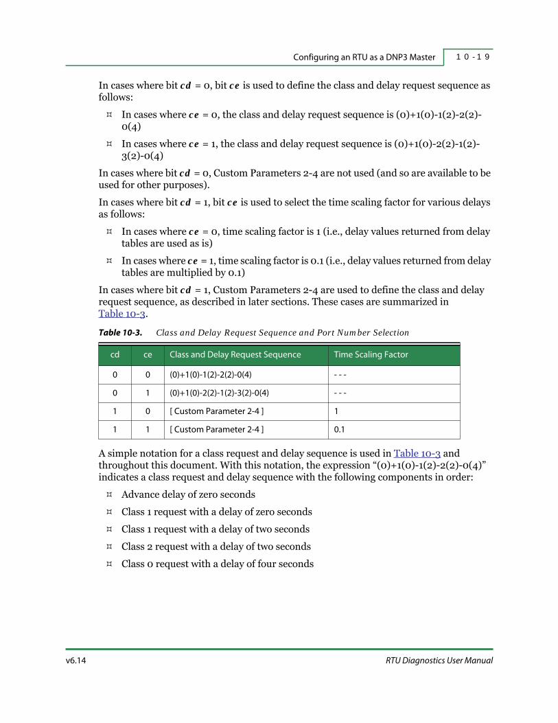
v6.14 RTU Diagnostics User Manual
Configuring an RTU as a DNP3 Master 1 0 - 1 9
In cases where bit cd = 0, bit ce is used to define the class and delay request sequence as follows:
In cases where ce = 0, the class and delay request sequence is (0)+1(0)-1(2)-2(2)-0(4)
In cases where ce = 1, the class and delay request sequence is (0)+1(0)-2(2)-1(2)-3(2)-0(4)
In cases where bit cd = 0, Custom Parameters 2-4 are not used (and so are available to be used for other purposes).
In cases where bit cd = 1, bit ce is used to select the time scaling factor for various delays as follows:
In cases where ce = 0, time scaling factor is 1 (i.e., delay values returned from delay tables are used as is)
In cases where ce = 1, time scaling factor is 0.1 (i.e., delay values returned from delay tables are multiplied by 0.1)
In cases where bit cd = 1, Custom Parameters 2-4 are used to define the class and delay request sequence, as described in later sections. These cases are summarized in Table 10-3.
A simple notation for a class request and delay sequence is used in Table 10-3 and throughout this document. With this notation, the expression “(0)+1(0)-1(2)-2(2)-0(4)” indicates a class request and delay sequence with the following components in order:
Advance delay of zero seconds
Class 1 request with a delay of zero seconds
Class 1 request with a delay of two seconds
Class 2 request with a delay of two seconds
Class 0 request with a delay of four seconds
Table 10-3. Class and Delay Request Sequence and Port Number Selection
cd ce Class and Delay Request Sequence Time Scaling Factor
0 0 (0)+1(0)-1(2)-2(2)-0(4) - - -
0 1 (0)+1(0)-2(2)-1(2)-3(2)-0(4) - - -
1 0 [ Custom Parameter 2-4 ] 1
1 1 [ Custom Parameter 2-4 ] 0.1

Configuration of the DNP3 Master1 0 - 2 0
HSQ Technology v6.14
Similarly, the expression “(0)+1(0)-2(2)-1(2)-3(2)-0(4)” indicates the following class request and delay sequence:
Advance delay of zero seconds
Class 1 request with a delay of zero seconds
Class 2 request with a delay of two seconds
Class 1 request with a delay of two seconds
Class 3 request with a delay of two seconds
Class 0 request with a delay of four seconds
In this notation, class requests are represented by the integer numbers 0, 1, 2, 3, and 123. Delays of all types are enclosed between parentheses. The Advance Delay is followed by a “+” sign. All delay values are in seconds. In cases where the Advance Delay is 0, the Advance Delay and the “+” sign can be omitted for simplicity, although this is not encouraged.
A different notation can be used to represent the class request and delay sequences. With this notation that separates class requests from delays, class request and delay sequences similar to the ones discussed above can be written as follows:
(0)+1(0)-1(0)-2(2)-0(4) = = 1-1-2-0:0-4-0-2-0-0
(0)+1(0)-2(2)-1(0)-3(5)-0(4) = = 1-2-1-3-0:0-4-0-2-5-0
While this notation is somewhat more compact and avoids repeating the delay information for the same class requests, it is difficult to associate delays with class requests, regardless of the order in which delays are written, and therefore this notation is not recommended.
10.3.7 | IP Address Table
DNP3 requires each device to have a Destination ID number, IP Address, and Port Number. In order to identify the device, RTUDiag is used to read each of these by using the command “Read RIO Config”. RTUDiag can insert a new entry, delete an entry, or edit an entry when the IP address table is open.
The IP address table needs to be saved in a file. Then, the command “Send RIO Config” is used to read the IP address table from the file. The IP address table can be modified, if desired, and downloaded to the RTU.
Each entry in the IP address table has three fields, as shown in Figure 10-12. One field, the RIO ID number, identifies a remote DNP device for the purpose of DNP3. The RIO ID number starts with the value 1 (i.e., the ID number cannot be zero) and it should match the value set for the field “MUX ID” in the point definition of all points associated with that DNP device. The next field is “IP ADDRESS”. The final field is the “PORT NUMBER”. It must read 20000, which is assigned to the DNP3 protocol.
Refer to “Network” on page 6-19 for more details.

v6.14 RTU Diagnostics User Manual
Configuring an RTU as a DNP3 Master 1 0 - 2 1
Figure 10-12. RTUDiagUser Interface with IP Address Table
10.3.8 | Sequence of Class Requests and Delay Requests
Points are grouped into classes and read access for point data is done by querying these classes. In addition to requests for classes (called class requests), there are predefined delays that the DNP3 Master can insert at the user's request (called delay requests), as explained below. The requests for classes or delays are expressed as integer numbers with values from 0 to 7, as shown in Table 10-4. A request value of 1 represents a Class 0 request, a request value of 2 represents a Class 1 request and so on. A request value of 5 represents a Class 123 request.
One or more requests form a request sequence. A request sequence may contain repetitions of the same requests placed randomly in the request sequence.
Requests values of 6 and 7 are special cases in which only delays are inserted into the request sequence but class requests are not. These requests are called delay requests.
Table 10-4. Selection of Class Requests and Delay Requests
Request Class Request Delay Request
0 - - - - - -
1 Class 0 - - -
2 Class 1 - - -
3 Class 2 - - -
4 Class 3 - - -
5 Class 123 - - -
6 - - - dlsS
7 - - - dlsE
Configuration of the DNP3 Master1 0 - 2 2
HSQ Technology v6.14
There are two delay requests called Short Sequential Delay (dlsS) corresponding to a request value of 6 and Extended Sequential Delay (dlsE) corresponding to a request value of 7. These two delays are called sequential because they implement delay subsequences within the request sequence when entered consecutively. These two sequential delays cannot be intermixed within the same delay subsequence. A short delay subsequence is ended by a request of any value other than dlsS or 0 (null request) An Extended Delay Subsequence is ended by a request of any value other than dlsE or 0 (null request). The number of sequential delays in a Delay Subsequence is referred to as the length of the Delay Subsequence; it cannot exceed the length of the sequence to which the subsequence belongs. The values of the delay produced by a Delay Subsequence depend on the number of sequential delays in the subsequence and do not follow a linear function. The values of these delays are generated by the use of tables in which the number of sequential delays is used as an index, as shown in later sections.
A request value of 0 is another special case. In this case, no class request and no delay request are inserted into the request sequence. For this reason, this request is called a null request. This request is used to preserve the position of the other requests in the request sequence in case a request is removed from the request sequence, making it easier to recalculate the value of the request sequence. For instance, consider the following request sequence:
(0)+1(2)-2(2)-3(4)-123(2)-4(4)
Assuming that a Class 3 request needs to be removed from the request sequence, the following two request sequences are equivalent but it is easier to recalculate the value of the request sequence in the case of the second request sequence:
(0)+1(2)-2(2)-123(2)-4(4)
(0)+1(2)-2(2)-n(0)-123(2)-4(4)
As noted in the above example, a null request (n) replaces the Class 3 request, preventing other requests from shifting within the request sequence and thus preserving the values of those requests in the calculated value of the request sequence. Only the value corresponding to the Class 3 request has to be subtracted from the value of the request sequence in order to obtain the new value of the request sequence. The value of the request sequence needs to be assigned to Custom Parameters, as shown in later sections.
The null request can be written as “n” for simplicity, however, the complete notation “n(0)” is preferred because it emphasizes the fact that the null request has no delay. It also maintains a uniform syntax of the notation for representing request sequences.
Each class request has a class delay associated with it, as shown in Table 10-5. Values for each class delay are generated by using a corresponding class delay index to extract class delay values from the tables. Class 0 Delay Index (dlx0) is used to generate the Class 0 delay which is associated with Class 0 requests, Class 1 Delay Index (dlx1) is used to generate the Class 1 delay which is associated with Class 1 requests, and so on. A same class delay is associated to all corresponding class requests in a request sequence, regardless of their placement in the request sequence or the number of instances in the request sequence. This means that all Class 0 requests in a request sequence have a Class

v6.14 RTU Diagnostics User Manual
Configuring an RTU as a DNP3 Master 1 0 - 2 3
0 delay, and so on. When the request sequence is processed, class delays are inserted before executing the corresponding class requests.
When the RTU code runs and the request sequence is executed (after the last request in the request sequence is executed), the request sequence is continuously repeated in a loop starting from the beginning, starting with the Advance Delay, as shown in Figure 10-13.
Figure 10-13. Request Sequence Example
The first entry in the request sequence is the Advance Delay. The first request in the request sequence (req_0), is a Class 2 request with its associated Class 2 delay. The second request (req_1), is a Null Request, somewhere in the middle of the request sequence (req_i) is a Short Sequential Delay. The next request (req_i+1), is a Class 1
Table 10-5. Correspondence of Class Requests, Class Delay Indices, and Class Delays
Request Class Request Class Delay Index Class Delay
1 Class 0 dlx0 Class 0
2 Class 1 dlx1 Class 1
3 Class 2 dlx2 Class 2
4 Class 3 dlx3 Class 3
5 Class 123 dlx123 Class 123

Configuration of the DNP3 Master1 0 - 2 4
HSQ Technology v6.14
request with its associated Class 1 delay. Finally, the last request in the request sequence (req_N), is a Class 0 request with its associated Class 0 delay.
Assuming an advance delay of two seconds and a one second delay for all class delays, this request sequence can be written as shown below:
(2)+2(1)-n(0)-n(s)-1(1)-0(1)
The Short Sequential Delay (dlsS), which is a delay request, can be written as “(s)”. However, the complete notation “n(s)” is preferred because it emphasizes the fact that a delay request is not associated to a class request (i.e., it is associated with a null request). It also maintains uniform notation syntax for representing request sequences. The same holds for the Extended Sequential Delay (dlsE).
With the above observation, the requests for classes or delays can be expressed more completely, as shown in table below:
Values of class delays are extracted from tables by the use of class delay indices. However, in the expression “1(2)”, value 2 is the value of class delay and not the value of class delay index.
The Advance Delay is, by default, the first entry in a request sequence. It does not need to be entered in the request sequence by a request. Similarly to class delays, values of the advance delay are extracted from tables by the use of Advance Delay Index (dlxA).
In cases where bit cd of Custom Parameter 1 is set to 1, a request sequence is defined by the content of Custom Parameters 2-4. The request sequence is transferred to an RTU by uploading Custom Parameters 2-4 with RTUDiag.
Bit cc, which is bit[15] of Custom Parameter 2, as shown in Figure 10-14, is used to select the data format of requests within request sequences.
Table 10-6. Selection of Class Requests and Delay Requests
Request Class Request Class Delay Index Class Delay Delay Request
0 null - - - - - - 0
1 Class 0 dlx0 Class 0 - - -
2 Class 1 dlx1 Class 1 - - -
3 Class 2 dlx2 Class 2 - - -
4 Class 3 dlx3 Class 3 - - -
5 Class 123 dlx123 Class 123 - - -
6 null - - - - - - dlsS
7 null - - - - - - dlsE

v6.14 RTU Diagnostics User Manual
Configuring an RTU as a DNP3 Master 1 0 - 2 5
10.3.8.1 | Custom Parameter 2
15 14 0
Figure 10-14. Custom Parameter 2 with Bit cc
Two data formats are used to represent requests, as shown in Table 10-7. When bit cc is set to 0, a request is represented in hexadecimal format. When bit cc is set to 1, a request is represented in octal format. The hexadecimal format for requests provides a format for Custom Parameters 2-4 and makes for an easier calculation of the value of a request sequence that will be written into Custom Parameters 2-4. The octal format, on the other hand, provides for a more compact format of Custom Parameters 2-4 and thus for more request entries per request sequence.
Bit cs, which is bit[15] of Custom Parameter 3, as shown in Figure 10-15, is used to provide an additional format for Custom Parameters 2-4 for each of the two data formats of the request.
10.3.8.2 | Custom Parameter 3
15 14 0
Figure 10-15. Custom Parameter 3 with Bit cs
The values of bit cc and of bit cs can be used to indicate which format of Custom Parameters 2-4 is used to implement a given request sequence. For this purpose, bit cc and bit cs are chained together to create the type of a request sequence, which can select, by itself, the format of Custom Parameters 2-4.
In order to provide the complete notation of a request sequence, the type of request sequence is placed as an integer value between square brackets at the beginning of the notation for request sequences, as shown below:
[0]+(0)+1(2)-2(2)-3(4)-123(2)-4(4)
When bit cc and bit cs are both set to 0, the construct for the request sequence type can be missing, yielding the notation for request sequences that are used in all of the previous
cc
Table 10-7. Data Format of Requests and Maximum Length of Request Sequence
cc cs Type of Request Sequence Data Format of RequestsNumber of Request Entries per
Sequence (N)
0 0 0 Hexadecimal 6
0 1 1 Hexadecimal 8
1 0 2 Octal 9
1 1 3 Octal 10
cs

Configuration of the DNP3 Master1 0 - 2 6
HSQ Technology v6.14
examples (i.e., without square brackets). This notation for request sequences, which yields a request sequence expression for any given request sequence (while currently not used by software), is a useful notation when it is necessary to specify a request sequence that will be written into Custom Parameters 2-4 and transferred to the RTU.
All formats of Custom Parameters 2-4 consist of tradeoffs between the number of requests per request sequence (i.e., the length of request sequence) and the time granularity of various delays. RTUDiag is normally used to set Custom Parameters 2-4 with the values of the request sequence and to transfer Custom Parameters 2-4 to an RTU, configuring the DNP3 Master with the class requests and delays of that particular request sequence.
10.3.9 | Request Sequences Represented in Hexadecimal Format
10.3.9.1 | Data Format of Requests and Delays
In cases where bit cc = 0, the length of request fields is generally four bits, as shown in Figure 10-16. There are a few exceptions with a length of three bits, when the high-order bit of a request is used for a control bit (such as bit cc or bit cs). Since a class request only takes values from 0 to 7, it is completely represented in three bits. The high-order bit of the request field (bit[3]) is, in the case of class requests, ignored. However, request fields are placed at 4-bit boundaries within Custom Parameters 2-4.
3 2 0
Figure 10-16. Format of Class Request Field, when cc = 0 (i = 0, 1, 2, ..., N)
In cases where bit cc = 0, the length of class delays is generally four bits, as shown in Figure 10-17. There are a few exceptions, as shown in later sections. All four bits of the delay field are used.
3 0
Figure 10-17. Format of Class Delay Field, when cc = 0 (j = 0, 1, 2, 3, 123)
Since a request is represented in hexadecimal format when bit cc is set to 0, it is normal to represent a request sequence in hexadecimal format as well. Bit cs of Custom Parameter 3 is used to select between the two formats of Custom Parameters 2-4, which are represented in hexadecimal and are described in later sections.
The values of Custom Parameters 2-4 are normally calculated in decimal format before being written.
req_i
delay j

v6.14 RTU Diagnostics User Manual
Configuring an RTU as a DNP3 Master 1 0 - 2 7
10.3.9.2 | Format of Custom Parameters 2-4, when cc=0 and cs=0
As described earlier, in cases when bit cc of Custom Parameter 2 is set to 0, the data format of requests is hexadecimal. The format of Custom Parameters 2-4, when bit cc of Custom Parameter 2 and bit cs of Custom Parameter 3 are both set to 0 (i.e., the request sequence type is 0), also resembles the hexadecimal format, as shown in Figure 10-18.
Custom Parameters 2-4 are defined so that they contain six request fields and six delay fields. This is the simplest and most straight-forward of all formats for Custom Parameters 2-4 and is intended to be sufficient in most situations. Other formats for Custom Parameters 2-4 are available for situations in which this format is not sufficient, as shown in later sections.
Custom Parameter 2 15 14 12 11 8 7 4 3 0
Custom Parameter 3 15 14 12 11 8 7 4 3 0
Custom Parameter 4 15 14 12 11 8 7 4 3 0
Figure 10-18. Format of Custom Parameters 2-4. when cc = 0 and cs = 0
The request fields are numbered from req_0 to req_5 and are placed at 4-bit boundaries. The requests are entered in the request sequence in ascending order of their indices (i.e., from req_0 to req_5). As described in previous sections, valid request values are from 0 to 7. Any of the requests from req_0 to req_5 can have any of the class request values from Class 0 requests to Class 123 requests, any of the delay request values (Short Sequential Delay or Extended Sequential Delay), or the null request, as shown in Table 10-6, “Selection of Class Requests and Delay Requests,” on page 10-24.
The delay fields are also placed at 4-bit boundaries and represent indices used to extract delay values from delay tables, as shown in Table 10-8 below. Class Delay Index (dlx0) returns a Class 0 Delay, Class Delay Index (dlx1) returns a Class 1 Delay, and so on. Bit dc, which is bit[15] of Custom Parameter 4, is used together with Class Delay Indexes to generate class delays.
0 req_1 req_0 dlxA dlx0
0 req_3 req_2 dlx2 dlx1
0 req_5 req_4 dlx123 dlx5
Table 10-8. Class j Delay when cc=0 and cs=0 (j=0, 1, 2, 3, 123)
dc dlxj Class j Delay [s] dc dlxj Class j Delay [s]
0 0 0 1 0 0
0 1 0.01 1 1 0.1
0 2 0.02 1 2 0.2

Configuration of the DNP3 Master1 0 - 2 8
HSQ Technology v6.14
In cases when bit cc is set to 0, the Advance Delay Index (dlxA) and bit dc (bit[15] of Custom Parameter 4) are used to generate the values of the Advance Delay, as shown in Table 10-9 below.
0 3 0.05 1 1 3 0.4
0 4 0.1 1 4 0.5
0 5 0.2 1 5 0.7
0 6 0.5 1 6 0.8
0 7 1 1 7 1
0 8 2 1 8 2
0 9 4 1 9 4
0 10 5 1 10 5
0 11 7 1 11 7
0 12 8 1 12 8
0 13 10 1 13 10
0 14 12 1 14 12
0 15 15 1 15 15
Table 10-9. Advance Delay when cc=0
dc dlxA Advance Delay [s] dc dlxA Advance Delay [s]
0 0 0 1 0 0
0 1 0.01 1 1 1
0 2 0.02 1 2 2
0 3 0.05 1 1 3 4
0 4 0.1 1 4 5
0 5 0.2 1 5 7
0 6 0.4 1 6 8
0 7 0.5 1 7 10
0 8 0.7 1 8 12
0 9 0.8 1 9 15
Table 10-8. Class j Delay when cc=0 and cs=0 (j=0, 1, 2, 3, 123) (continued)
dc dlxj Class j Delay [s] dc dlxj Class j Delay [s]
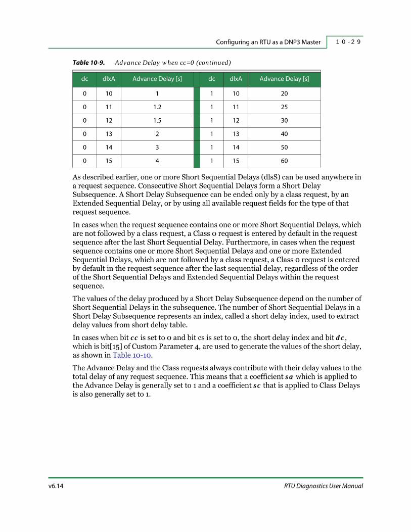
v6.14 RTU Diagnostics User Manual
Configuring an RTU as a DNP3 Master 1 0 - 2 9
As described earlier, one or more Short Sequential Delays (dlsS) can be used anywhere in a request sequence. Consecutive Short Sequential Delays form a Short Delay Subsequence. A Short Delay Subsequence can be ended only by a class request, by an Extended Sequential Delay, or by using all available request fields for the type of that request sequence.
In cases when the request sequence contains one or more Short Sequential Delays, which are not followed by a class request, a Class 0 request is entered by default in the request sequence after the last Short Sequential Delay. Furthermore, in cases when the request sequence contains one or more Short Sequential Delays and one or more Extended Sequential Delays, which are not followed by a class request, a Class 0 request is entered by default in the request sequence after the last sequential delay, regardless of the order of the Short Sequential Delays and Extended Sequential Delays within the request sequence.
The values of the delay produced by a Short Delay Subsequence depend on the number of Short Sequential Delays in the subsequence. The number of Short Sequential Delays in a Short Delay Subsequence represents an index, called a short delay index, used to extract delay values from short delay table.
In cases when bit cc is set to 0 and bit cs is set to 0, the short delay index and bit dc, which is bit[15] of Custom Parameter 4, are used to generate the values of the short delay, as shown in Table 10-10.
The Advance Delay and the Class requests always contribute with their delay values to the total delay of any request sequence. This means that a coefficient sa which is applied to the Advance Delay is generally set to 1 and a coefficient sc that is applied to Class Delays is also generally set to 1.
0 10 1 1 10 20
0 11 1.2 1 11 25
0 12 1.5 1 12 30
0 13 2 1 13 40
0 14 3 1 14 50
0 15 4 1 15 60
Table 10-9. Advance Delay when cc=0 (continued)
dc dlxA Advance Delay [s] dc dlxA Advance Delay [s]

Configuration of the DNP3 Master1 0 - 3 0
HSQ Technology v6.14
In cases of a Short Delay Subsequence, coefficients sa and sc are not always set to 1. In order to calculate the delay of a Short Delay Subsequence, the coefficient sa is applied to the Advance Delay and the coefficient sc is applied to the Class Delay of the class request which ends the Short Delay Subsequence, as shown by the following formula:
Delay_{Short_subseq} = Short_delay + sa*Advance_delay + sc*Class_j_delay
Where j = 0, 1, 2, 3, or 123.
One or more Extended Sequential Delays (dlsE) can be used anywhere in a request sequence. Consecutive Extended Sequential Delays form an Extended Delay subsequence. An Extended Delay Subsequence can be ended only by a class request, by a Short Sequential Delay, or by using all of the available request fields for the type of that request sequence.
In cases when the request sequence contains one or more Extended Sequential Delays, which are not followed by a class request, a Class 0 request is entered by default in the request sequence after the last Short Sequential Delay. In cases when the request sequence contains one or more Short Sequential Delays and one or more Extended Sequential Delays, which are not followed by a class request, a Class 0 request is entered by default in the request sequence after the last sequential delay, regardless of the order of the Short Sequential Delays and Extended Sequential Delays within the request sequence.
The values of the delay produced by an Extended Delay Subsequence depend on the number of Extended Sequential Delays in the subsequence. The number of Extended Sequential Delays in an Extended Delay Subsequence represents an index, called the Extended Delay Index, and is used to extract delay values from the Extended Delay Table.
In cases when bit cc is set to 0 and bit cs is set to 0, the Extended Delay Index and bit dc, which is bit[15] of Custom Parameter 4, are used to generate the values of the Extended Delay, as shown in Table 10-11.
Table 10-10. Short Delay when cc=0 and cs=0
dcShort Delay
Subsequence
Short
Delay [s]sa sc dc
Short Delay
Subsequence
Short
Delay [s]sa sc
0 0 x dlsS 0 1 1 1 0 x dlsS 0 1 1
0 1 x dlsS 0.1 1 1 1 1 x dlsS 1 1 1
0 2 x dlsS 0.4 1 1 1 2 x dlsS 4 1 1
0 3 x dlsS 0.7 1 1 1 1 3 x dlsS 7 1 1
0 4 x dlsS 1 1 1 1 4 x dlsS 15 1 1
0 5 x dlsS 4 1 1 1 5 x dlsS 30 1 1
0 6 x dlsS 7 1 1 1 6 x dlsS 60 1 4

v6.14 RTU Diagnostics User Manual
Configuring an RTU as a DNP3 Master 1 0 - 3 1
The Advance Delay and the Class requests always contribute with their delay values to the delay of any request sequence. This means that a coefficient sa which is applied to the Advance Delay is generally set equal to 1 and a coefficient sc that is applied to Class Delays is also generally set to 1.
In cases of an Extended Delay Subsequence, the coefficients sa and sc are not always set to 1. In order to calculate a delay in the case of an Extended Delay Subsequence, coefficient sa is applied to the Advance Delay and coefficient sc is applied to the Class Delay of the class request that ends the Extended Delay Subsequence, as shown by the following formula:
Delay_{Extended_subseq} = Extended_delay + sa*Advance_delay + sc*Class_j_delay
Where j = 0, 1, 2, 3, or 123.
Example 1
As an example, the following request sequence will be converted into values for Custom Parameters 2-4.
[0]+(0)+1(0)-1(2)-2(2)-0(4)
Since Class 1 delays can only have one value (in this example, it is the minimum value between zero and two seconds), the request sequence is rewritten in the correct syntax by inserting an Extended Sequential Delay that provides a delay of two seconds, in cases when bit dc=1, as follows:
[0][0]+(0)+1(0)-n(e)-1(0)-2(2)-0(4)
The request sequence is rewritten again to include delay indices by using the delay values and index values in Table 10-8, “Class j Delay when cc=0 and cs=0 (j=0, 1, 2, 3, 123),” on page 10-27 and Table 10-9, “Advance Delay when cc=0,” on page 10-28, as follows:
[8][1024][0][0]+(0/0)+1(0/0)-n(e)-1(0/0)-2(2/8)-0(4/9)
Table 10-11. Extended Delay when cc=0 and cs=0
dcExtended Delay
Subsequence
Extended
Delay [s]ea ec dc
Extended Delay
Subsequence
Extended
Delay [s]ea ec
0 0 x dlsE 0 1 1 1 0 x dlsE 0 1 1
0 1 x dlsE 0.2 1 1 1 1 x dlsE 2 1 1
0 2 x dlsE 0.5 1 1 1 2 x dlsE 5 1 1
0 3 x dlsE 1 1 1 1 1 3 x dlsE 10 1 1
0 4 x dlsE 2 1 1 1 4 x dlsE 20 1 1
0 5 x dlsE 5 1 1 1 5 x dlsE 45 1 1
0 6 x dlsE 10 1 2 1 6 x dlsE 120 2 4

Configuration of the DNP3 Master1 0 - 3 2
HSQ Technology v6.14
The expression “[8]” means bit cd=1 and the expression “[1024]”means field si=1024. The expression “[0]” means bit cc=0, bit cs=0 (i.e., request sequence type is 0), and the expression “[0]”, which follows the former expression, means bit dc=0. This form of the request sequence can now be written into Custom Parameters 2-4 as shown below. Custom Parameter 1 holds the source ID number, which is set to decimal value 1024.
Custom Parameter 1 15 14 13 12 11 0
Custom Parameter 2 15 14 12 11 8 7 4 3 0
Custom Parameter 3 15 14 12 11 8 7 4 3 0
Custom Parameter 4 15 14 12 11 8 7 4 3 0
A hexadecimal-to-decimal converter is used to obtain the following values in decimal format:
Custom Parameter 1: 0x8400 = 33792Custom Parameter 2: 0x7209 = 29193Custom Parameter 3: 0x3280 = 12928Custom Parameter 4: 0x8100 = 33024
The request sequence of this example is the first default request sequence, as shown in Table 10-3, “Class and Delay Request Sequence and Port Number Selection,” on page 10-19. In this particular case, the request sequence can be written as follows:
[0][1024]
This request sequence yields the following values in decimal format:
Custom Parameter 1: 0x0400 = 1024Custom Parameter 2: 0x0000 = 0Custom Parameter 3: 0x0000 = 0Custom Parameter 4: 0x0000 = 0In this particular case, Custom Parameters 2-4 are available to be used for other purposes.
1 0 0 0 0x0400
0 req_1 = 7 req_0 = 2 dlxA = 0 dlx0 = 9
0 req_3 = 3 req_2 = 2 dlx2 = 8 dlx1 = 0
1 req_5 req_4 = 1 dlx123 dlx3

v6.14 RTU Diagnostics User Manual
Configuring an RTU as a DNP3 Master 1 0 - 3 3
Example 2
As an example, the following request sequence will be converted into values for Custom Parameters 2-4.
[0]+(1)+1(2)-2(4)-3(5)-123(8)-0(13)
The request sequence is rewritten by inserting a Short Sequential Delay, which provides an additional delay of one second for Class 0 requests, for a total delay of thirteen seconds for Class 0 requests, as follows:
[8][1024][0][1]+(1)+1(2)-2(4)-3(5)-123(8)-n(s)-0(12)
The expression “[8]” means bit cd=1 and the expression “[1024]”means field si=1024. The expression “[0]” means bit cc=0 and bit cs=0 (i.e., the request sequence type is 0) and the expression “[1]”, which follows the former expression, means bit dc=1. The request sequence is rewritten again to include delay indexes by using the delay values and index values in Table 10-8, “Class j Delay when cc=0 and cs=0 (j=0, 1, 2, 3, 123),” on page 10-27 and Table 10-9, “Advance Delay when cc=0,” on page 10-28, as follows:
[8][1024][0][1]+(1/1)+1(2/8)-2(4/9)-3(5/10)-123(8/12)-n(s)-0(12/14)
This form of the request sequence can now be written into Custom Parameters 2-4, as shown below. Custom Parameter 1 holds the source ID number, which is set to decimal value 1024.
Custom Parameter 1 15 14 13 12 11 0
Custom Parameter 2 15 14 12 11 8 7 4 3 0
Custom Parameter 3 15 14 12 11 8 7 4 3 0
Custom Parameter 4 15 14 12 11 8 7 4 3 0
1 0 0 0 0x0400
0 req_1 = 3 req_0 = 2 dlxA = 1 dlx0 = 14
0 req_3 = 5 req_2 = 4 dlx2 = 9 dlx1 = 8
1 req_7 = 1 req_4 = 6 dlx123 = 12 dlx3 = 10

Configuration of the DNP3 Master1 0 - 3 4
HSQ Technology v6.14
A hexadecimal-to-decimal converter is used to obtain the following values in decimal format:
Custom Parameter 1: 0x8400 = 33792Custom Parameter 2: 0x321E = 12830Custom Parameter 3: 0x5498 = 21656Custom Parameter 4: 0x96CA = 38602
A Class 0 request is entered by default in cases where a combination of Short and Extended Sequential Delays are not terminated; the following request sequence is equivalent to the above request sequence:
[8][1024][0][1]+(1/1)+1(2/8)-2(4/9)-3(5/10)-123(8/12)-n(s)-n(e)+0(10/13)
A Short Sequential Delay and an Extended Sequential Delay, in any order, provide an additional delay of three seconds for Class 0 requests (which are entered by default) for a total delay of thirteen seconds for Class 0 requests.
This form of the request sequence can be written into Custom Parameters 2-4, as shown below. Custom Parameter 1 holds the source ID number, which is set to decimal value 1024.
Custom Parameter 1 15 14 13 12 11 0
Custom Parameter 2 15 14 12 11 8 7 4 3 0
Custom Parameter 3 15 14 12 11 8 7 4 3 0
Custom Parameter 4 15 14 12 11 8 7 4 3 0
A hexadecimal-to-decimal converter is used to obtain the following values in decimal format:
Custom Parameter 1: 0x8400 = 33792Custom Parameter 2: 0x321D = 12829Custom Parameter 3: 0x5498 = 21656Custom Parameter 4: 0xF6CA = 63178
1 0 0 0 0x0400
0 req_1 = 3 req_0 = 2 dlxA = 1 dlx0 = 13
0 req_3 = 5 req_2 = 4 dlx2 = 9 dlx1 = 8
1 req_7 = 7 req_4 = 6 dlx123 = 12 dlx3 = 10

v6.14 RTU Diagnostics User Manual
Configuring an RTU as a DNP3 Master 1 0 - 3 5
Similarly, the following request sequence is equivalent to the above request sequence:
[8][1024][0][1]+(1/1)+1(2/8)-2(4/9)-3(5/10)-123(8/12)-n(e)-n(e)+0(8/12)
An Extended Delay Subsequence of two Extended Sequential Delays provides an additional delay of five seconds for Class 0 requests (which are entered by default) for a total delay of thirteen seconds for Class 0 requests.
This form of the request sequence can be written into Custom Parameters 2-4, as shown below. Custom Parameter 1 holds the source ID number, which is set to decimal value 1024.
Custom Parameter 1 15 14 13 12 11 0
Custom Parameter 2 15 14 12 11 8 7 4 3 0
Custom Parameter 3 15 14 12 11 8 7 4 3 0
Custom Parameter 4 15 14 12 11 8 7 4 3 0
A hexadecimal-to-decimal converter is used to obtain the following values in decimal format:
Custom Parameter 1: 0x8400 = 33792Custom Parameter 2: 0x321C = 12828Custom Parameter 3: 0x5498 = 21656Custom Parameter 4: 0xF7CA = 63434
Example 3
As an example, Short and/or Extended Sequential Delays and/or Delay Subsequences are used to provide various delays, as shown in Table 10-12. Delay values are in seconds, which means that bit ce, which is bit[14] of Custom Parameter 1, is set to 0.
1 0 0 0 0x0400
0 req_1 = 3 req_0 = 2 dlxA = 1 dlx0 = 12
0 req_3 = 5 req_2 = 4 dlx2 = 9 dlx1 = 8
1 req_7 = 7 req_4 = 7 dlx123 = 12 dlx3 = 10

Configuration of the DNP3 Master1 0 - 3 6
HSQ Technology v6.14
Table 10-12. Short and/or Extended Sequential Delays and/or Delay Subsequence
Sequential Delay or Delay Subsequence Delay[s]
- - - 0
n(s) 1
n(e) 2
n(s)-n(e); n(e)-n(s) 3
n(s)-n(s) 4
n(e)-n(e) 5
n(s)-n(s)-n(e); n(e)-n(s)-n(s) ; n(s)-n(e)-n(e) ; n(e)-n(e)-n(s) ; [ n(s)-n(e)-n(s)-n(e) ] 6
n(s)-n(s)-n(s) 7
n(e)-n(s)-n(e)-n(e) ; n(e)-n(e)-n(s)-n(e) ; n(e)-n(s)-n(s)-n(e) 8
n(s)-n(s)-n(s)-n(e) ; n(e)-n(s)-n(s)-n(s) 9
n(e)-n(e)-n(e) 10
n(s)-n(e)-n(e)-n(e) ; n(e)-n(e)-n(e)-n(s) 11
n(s)-n(e)-n(e)-n(e)-n(s) ; n(s)-n(s)- n(s)-n(e)-n(e) ; n(e)-n(e)-n(s)-n(s)-n(s) 12
n(e)-n(s)-n(e)-n(e)-n(e) ; n(e)-n(e)-n(e)-n(s)-n(e) ; [ n(s)-n(s)-n(s)-n(e)-n(e)-n(s) ] 13
n(s)-n(s)-n(e)-n(e)-n(e) ; n(e)-n(e)-n(e)-n(s)-n(s) ; [ n(e)-n(s)-n(s) n(s)-n(e)-n(e) ] 14
n(s)-n(s)-n(s)-n(s) 15
n(e)-n(e)-n(s)-n(e)-n(e)-n(e) ; n(e)-n(e)-n(e)-n(s)-n(e)-n(e) ; n(e)-n(s)-n(s)-n(e)-n(e)-n(e) 16
n(s)-n(s)-n(s)-n(s)-n(e) ; n(e)-n(s)-n(s)-n(s)-n(s) 17
n(s)-n(s)-n(s)-n(s)-n(e)-n(s) ; n(s)-n(e)-n(s)-n(s)-n(s)-n(s) 18
n(e)-n(s)-n(s)-n(s)-n(s)-n(e) ; 19
n(e)-n(e)-n(e)-n(e) 20
n(s)-n(e)-n(e)-n(e)-n(e) ; n(e)-n(e)-n(e)-n(e)-n(s) 21
n(s)-n(e)-n(e)-n(e)-n(e)-n(s) ; 22
n(e)-n(s)-n(e)-n(e)-n(e)-n(e) ; n(e)-n(e)-n(e)-n(e)-n(s)-n(e) 23
n(s)-n(s)-n(e)-n(e)-n(e)-n(e) ; n(e)-n(e)-n(e)-n(e)-n(s)-n(s) 24
n(s)-n(s)-n(s)-n(s)-n(s) 30

v6.14 RTU Diagnostics User Manual
Configuring an RTU as a DNP3 Master 1 0 - 3 7
10.3.9.3 | Format of Custom Parameters 2-4, when cc=0 and cs=1
As described earlier, in cases when bit cc of Custom Parameter 2 is set to 0, the data format of requests is hexadecimal. The format of Custom Parameters 2-4 when bit cc of Custom Parameter 2 is set to 0 and bit cs of Custom Parameter 3 is set to 1 (i.e., the request sequence type is 1) also resembles the hexadecimal format with some exceptions, as shown in Figure 10-19. Custom Parameters 2-4 are defined to contain eight request fields and five delay fields.
Custom Parameter 2 15 14 12 11 8 7 4 3 0
Custom Parameter 3 15 14 12 11 8 7 4 3 0
Custom Parameter 4 15 14 13 12 11 10 9 8 7 4 3 0
Figure 10-19. Format of Custom Parameters 2-4, when cc=0 and cs=1
The request fields are numbered from req_0 to req_7 and are placed at 4-bit boundaries. The requests are entered in the request sequence in ascending order of their indices, that is, from req_0 to req_7. As described in previous sections, valid request values are from 0 to 7. Any of the requests from req_0 to req_7 can have any of the class request values from a Class 0 request to a Class 123 request, any of the delay request values (Short Sequential Delay or Extended Sequential Delay), or the null request, as shown in Table 10-6, “Selection of Class Requests and Delay Requests,” on page 10-24.
The delay fields are also placed at 4-bit boundaries, with some exceptions, such as the class delay field dlx2. Also, the class delay field dlx123 is entirely missing and so Class 123 delay is generated implicitly, as described later. The delay fields represent indices used to extract delay values from delay tables. Class Delay Index (dlx0) returns a Class 0 Delay, Class Delay Index (dlx1) returns a Class 1 Delay, and so on. Class Delay Index (dlx0) and bit dc, which is bit[15] of Custom Parameter 4, are used to generate the values of a Class 0 Delay, as shown in Table 10-13.
0 req_3 req_2 req_1 req_0
1 req_7 req_6 req_5 req_4
dc ds dlx3 dlx2 dlx1 dlxA dlx0
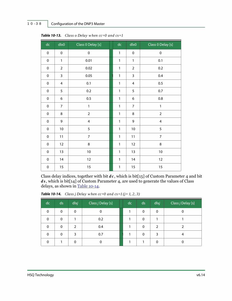
Configuration of the DNP3 Master1 0 - 3 8
HSQ Technology v6.14
Class delay indices, together with bit dc, which is bit[15] of Custom Parameter 4 and bit ds, which is bit[14] of Custom Parameter 4, are used to generate the values of Class delays, as shown in Table 10-14.
Table 10-13. Class o Delay when cc=0 and cs=1
dc dlx0 Class 0 Delay [s] dc dlx0 Class 0 Delay [s]
0 0 0 1 0 0
0 1 0.01 1 1 0.1
0 2 0.02 1 2 0.2
0 3 0.05 1 1 3 0.4
0 4 0.1 1 4 0.5
0 5 0.2 1 5 0.7
0 6 0.5 1 6 0.8
0 7 1 1 7 1
0 8 2 1 8 2
0 9 4 1 9 4
0 10 5 1 10 5
0 11 7 1 11 7
0 12 8 1 12 8
0 13 10 1 13 10
0 14 12 1 14 12
0 15 15 1 15 15
Table 10-14. Class j Delay when cc=0 and cs=1 (j= 1, 2, 3)
dc ds dlxj Class j Delay [s] dc ds dlxj Class j Delay [s]
0 0 0 0 1 0 0 0
0 0 1 0.2 1 0 1 1
0 0 2 0.4 1 0 2 2
0 0 3 0.7 1 1 0 3 4
0 1 0 0 1 1 0 0

v6.14 RTU Diagnostics User Manual
Configuring an RTU as a DNP3 Master 1 0 - 3 9
The Class Delay Index (dlx123) is missing. In this case, bit dc, which is bit[15] of Custom Parameter 4 and bit ds, which is bit[14] of Custom Parameter 4, are used to generate the values of a Class 123 Delay, as shown in Table 10-15.
In cases where bit cc is set to 0, the Advance Delay Index (dlxA) and bit dc, which is bit[15] of Custom Parameter 4, are used to generate the values of an Advance Delay, as shown in Table 10-9, “Advance Delay when cc=0,” on page 10-28.
In cases where bit cc is set to 0 and bit cs is set to 1, the number of consecutive Short Sequential Delays and bit dc, which is bit[15] of Custom Parameter 4, are used to generate the values of the Short Delay as described in “In cases where bit cc is set to 1 and bit cs is set to 0, the number of consecutive Short Sequential Delays and bit dc, which is bit[15] of Custom Parameter 4, are used to generate the values of Short Delay, as described in “One or more Short Sequential Delays (dlsS) can be used anywhere in a request sequence. Consecutive Short Sequential Delays form a Short Delay Subsequence. A Short Delay Subsequence can be terminated only by a class request, by an Extended Sequential Delay, or by using all available request fields for the type of request sequence. A Short Delay Subsequence is not terminated by a null request.” on page 10-49. A maximum number of nine Short Sequential Delays can be used as an input in Table 10-20, “Short Delay when cc=1 and/or cs=1,” on page 10-50.” on page 10-44. A maximum number of eight Extended Sequential Delays can be used as an input in Table 10-20, “Short Delay when cc=1 and/or cs=1,” on page 10-50.
In cases where bit cc is set to 0 and bit cs is set to 1, the number of consecutive Extended Sequential Delays and bit dc, which is bit[15] of Custom Parameter 4, are used to generate the values of the Extended Delay, as described in Section 3.12.3.6. A maximum number of eight Extended Sequential Delays can be used as input in Table 10-21, “Extended Delay when cc=1 and/or cs=1,” on page 10-51.
0 1 1 1 1 1 1 7
0 1 2 2 1 1 2 10
0 1 3 4 1 1 3 15
Table 10-15. Class 123 Delay when cc=0 and cs=1
dc ds Class 123 Delay [s]
0 0 Class 1 Delay
0 1 Class 2 Delay
1 0 Class 3 Delay
1 1 Class 123 Delay
Table 10-14. Class j Delay when cc=0 and cs=1 (j= 1, 2, 3) (continued)
dc ds dlxj Class j Delay [s] dc ds dlxj Class j Delay [s]

Configuration of the DNP3 Master1 0 - 4 0
HSQ Technology v6.14
Example 1
As an example, the following request sequence will be converted into values for Custom Parameters 2-4.
(0)+1(0)-2(2)-1(2)-3(2)-0(4)
Since Class 1 Delays can only have one value (in this example, it is the minimum value between zero and two seconds), the request sequence is rewritten in the correct syntax by inserting an Extended Sequential Delay that provides a delay of two seconds, in cases when bit dc=1, as follows:
[8][1024][1][2]+(0)+1(0)-2(2)-n(e)-1(0)-3(2)-0(4)
The expression “[8]” indicates bit cd=1 and the expression “[1024]” indicates field si=1024. The expression “[1]” means bit cc=0 and bit cs=1 (i.e., request sequence type is 1) and the expression “[2]”, which follows the former expression, means bit dc=1 and bit ds=0. The request sequence is rewritten again to include delay indices by using the delay values and index values in Table 10-9, “Advance Delay when cc=0,” on page 10-28, Table 10-13, “Class o Delay when cc=0 and cs=1,” on page 10-38, and Table 10-14, “Class j Delay when cc=0 and cs=1 (j= 1, 2, 3),” on page 10-38, and as follows:
[8][1024][1][2]+(0/0)+1(0/0)-2(2/2)-n(e)-1(0/0)-3(2/2)-0(4/9)
This form of the request sequence can now be written into Custom Parameters 2-4, as shown below, by using the delay values and index values in Table 10-8, “Class j Delay when cc=0 and cs=0 (j=0, 1, 2, 3, 123),” on page 10-27. Custom Parameter 1 holds the source ID number, which is set to decimal value 1024.
Custom Parameter 1 15 14 13 12 11 0
Custom Parameter 2 15 14 12 11 8 7 4 3 0
Custom Parameter 3 15 14 12 11 8 7 4 3 0
Custom Parameter 4 15 14 13 12 11 10 9 8 7 4 3 0
1 0 0 0 0x0400
0 req_3 = 2 req_2 = 7 req_1 = 3 req_0 = 2
1 req_7 req_6 req_5 = 1 req_4 = 4
1 0 dlx3=2 dlx2=2 dlx1=0 dlxA = 0 dlx0 = 9

v6.14 RTU Diagnostics User Manual
Configuring an RTU as a DNP3 Master 1 0 - 4 1
A hexadecimal-to-decimal converter is used to obtain the following values in decimal format:
Custom Parameter 1: 0x8400 = 33792Custom Parameter 2: 0x2732 = 10034Custom Parameter 3: 0x8014 = 32788Custom Parameter 4: 0xA809 = 43017
The request sequence of this example is the first default request sequence, as shown in Table 10-3, “Class and Delay Request Sequence and Port Number Selection,” on page 10-19. In this particular case, the request sequence can be written as follows:
[4][1024]
This request sequence yields the following values in decimal format:
Custom Parameter 1: 0x4400 = 17408Custom Parameter 2: 0x0000 = 0Custom Parameter 3: 0x0000 = 0Custom Parameter 4: 0x0000 = 0
In this particular case, Custom Parameters 2-4 are available to be used for other purposes.
Example 2
As an example, the following request sequence will be converted into values for Custom Parameters 2-4.
[1]+(1)+1(2)-2(3)-3(5)-123(6)-0(13)
The request sequence is rewritten by inserting Short and Extended Sequential Delays, which provide additional delays where necessary. A Class 0 request (with a Class 0 delay of twelve seconds), is entered by default after the last Short Sequential Delay, as follows:
[1][2]+(1)+1(2)-n(s)-2(2)-n(s)-3(4)-n(e)-123()-n(s)+0(12)
The expression “[1]” means bit cc=0 and bit cs=1 (i.e., the request sequence type is 1), and the expression “[2]”, which follows the former expression, means bit dc=1 and bit ds=0. The expression “123()” means that Class 123 request is missing its own Class 123 delay and instead receives a Class 3 delay since bit dc=1. With the additional Extended Sequential Delay, a Class 123 request has a delay of six seconds. The request sequence is rewritten again to include delay indexes by using the delay values and index values in Table 10-9 on page 10-28, Table 10-13 on page 10-38, Table 10-14 on page 10-38, Table 10-15 on page 10-39, and as follows:
[8][2048][1][2]+(1/1)+1(2/2)-n(s)-2(2/2)-n(s)-3(4/3)-n(e)-123()-n(s)+0(12/14)

Configuration of the DNP3 Master1 0 - 4 2
HSQ Technology v6.14
The expression “[8]” means bit cd=1 and the expression “[1024]”means field si=1024. This form of the request sequence can be written into Custom Parameters 2-4, as shown below. Custom Parameter 1 holds the source ID number, which is set to decimal value 2048.
Custom Parameter 1 15 14 13 12 11 0
Custom Parameter 2 15 14 12 11 8 7 4 3 0
Custom Parameter 3 15 14 12 11 8 7 4 3 0
Custom Parameter 4 15 14 13 12 11 10 9 8 7 4 3 0
A hexadecimal-to-decimal converter is used to obtain the following values in decimal format:
Custom Parameter 1: 0x8800 = 34816Custom Parameter 2: 0x6362 = 25442Custom Parameter 3: 0xE574 = 58740Custom Parameter 4: 0xBA1E = 47646
10.3.10 | Request Sequences Represented in Octal Format
10.3.10.1 | Format of Requests and Delays
In cases where bit cc = 1, the length of request fields is three bits, as shown in Figure 10-20.
2 0
Figure 10-20. Format of Class Request Field, when cc = 1 (i = 0, 1, 2, …, N)
In cases where bit cc = 1, the length of class delays is generally three bits, as shown in Figure 10-21. There are a few exceptions, as shown in later sections. All three bits of the delay fields are used.
2 0
Figure 10-21. Format of Class Delay Field when cc = 1 (j = 0, 1, 2, 3, 123)
1 0 0 0 0x0800
0 req_3 = 6 req_2 = 3 req_1 = 6 req_0 = 2
1 req_7 = 6 req_6 = 5 req_5 = 7 req_4 = 4
1 0 dlx3=3 dlx2=2 dlx1=2 dlxA = 1 dlx0 = 14
req_i
delay_j

v6.14 RTU Diagnostics User Manual
Configuring an RTU as a DNP3 Master 1 0 - 4 3
Since a request is represented in octal when bit cc is set to 1, it represents a request sequence in hexadecimal format. As stated above, bit cs of Custom Parameter 3 is used to select between the two formats of Custom Parameters 2-4, which are represented in octal and are described in later sections.
The values of Custom Parameters 2-4 are normally calculated in decimal format before being written into Custom Parameters 2-4.
10.3.10.2 | Format of Custom Parameters 2-4, when cc=1 and cs=0
In cases where bit cc of Custom Parameter 2 is set to 1, the data format of requests is octal. The format of Custom Parameters 2-4 when bit cc of Custom Parameter 2 is set to 1 and bit cs of Custom Parameter 3 is set to 0 (i.e., the request sequence type is 2) is also the octal format, as shown in Figure 10-22. Custom Parameters 2-4 are defined to contain nine request fields and six delay fields.
The request fields are numbered from req_0 to req_8 and are placed at 3-bit boundaries. The requests are entered in the request sequence in ascending order of their indices, that is, from req_0 to req_8. As described in previous sections, valid request values are from 0 to 7. Any of the requests from req_0 to req_7 can have any of the class request values from a Class 0 request to a Class 123 request, or any of the delay request values (Short Sequential Delay or Extended Sequential Delay), or the null request, as shown in Table 10-6 on page 10-24.
Custom Parameter 2 15 14 12 11 9 8 6 5 3 2 0
Custom Parameter 3 15 14 12 11 9 8 6 5 3 2 0
Custom Parameter 4 15 14 12 11 9 8 6 5 3 2 0
Figure 10-22. Format of Custom Parameters 2-4, when cc = 1 and cs = 0
The delay fields are also placed at 3-bit boundaries and represent indices used to extract delay values from the delay tables, as shown in Table 10-16. Class Delay Index (dlx0) returns Class 0 Delay, Class Delay Index (dlx1) returns Class 1 Delay, and so on. Bit dc, which is bit[15] of Custom Parameter 4, is used together with class delay indices to generate class delays.
1 req_2 req_1 req_0 dlxA dlx0
0 req_5 req_4 req_3 dlx2 dlx1
dc req_8 req_7 req_6 dlx123 dlx3

Configuration of the DNP3 Master1 0 - 4 4
HSQ Technology v6.14
In cases where bit cc is set to 1, the Advance Delay Index (dlxA) and bit dc, which is bit[15] of Custom Parameter 4, are used to generate the values of an Advance Delay, as shown in Table 10-17.
In cases where bit cc is set to 1 and bit cs is set to 0, the number of consecutive Short Sequential Delays and bit dc, which is bit[15] of Custom Parameter 4, are used to generate the values of Short Delay, as described in “One or more Short Sequential Delays (dlsS) can be used anywhere in a request sequence. Consecutive Short Sequential Delays form a Short Delay Subsequence. A Short Delay Subsequence can be terminated only by a class request, by an Extended Sequential Delay, or by using all available request fields for the type of request sequence. A Short Delay Subsequence is not terminated by a null request.” on page 10-49. A maximum number of nine Short Sequential Delays can be used as an input in Table 10-20, “Short Delay when cc=1 and/or cs=1,” on page 10-50.
Table 10-16. Class j Delay, when cc=1 (j = 0, 1, 2, 3, 123)
dc dlxA Advance Delay [s] dc dlxA Advance Delay [s]
0 0 0 1 0 0
0 1 0.1 1 1 1
0 2 0.2 1 2 2
0 3 0.4 1 1 3 4
0 4 0.7 1 4 5
0 5 1 1 5 7
0 6 2 1 6 10
0 7 4 1 7 15
Table 10-17. Advance Delay, when cc=1
dc dlxA Advance Delay [s] dc dlxA Advance Delay [s]
0 0 0 1 0 0
0 1 0.2 1 1 1
0 2 0.4 1 2 2
0 3 0.7 1 1 3 4
0 4 1 1 4 7
0 5 2 1 5 15
0 6 4 1 6 30
0 7 7 1 7 60

v6.14 RTU Diagnostics User Manual
Configuring an RTU as a DNP3 Master 1 0 - 4 5
In cases where bit cc is set to 1 and bit cs is set to 0, the number of consecutive Extended Sequential Delays and bit dc, which is bit[15] of Custom Parameter 4, are used to generate the values of Extended Delay, as described in “One or more Extended Sequential Delays (dlsE) can be used anywhere in a request sequence. Consecutive Extended Sequential Delays form an Extended Delay Subsequence. An Extended Delay Subsequence can be ended only by a class request, a Short Sequential Delay, or by using all available request fields for the type of that request sequence. An Extended Delay Subsequence is not ended by a null request.” on page 10-50. A maximum number of nine Extended Sequential Delays can be used as input in Table 10-21, “Extended Delay when cc=1 and/or cs=1,” on page 10-51.
Example 1
As an example, the following request sequence will be converted into values for Custom Parameters 2-4.
[2]+(1)+1(2)-2(3)-3(5)-123(6)-0(9)
The request sequence is rewritten by inserting Short and Extended Sequential Delays that provide additional delays where necessary. A Short Sequential Delay and an Extended Sequential Delay, in any order, provide an additional delay of three seconds for a Class 0 request (entered by default after the last Extended Sequential Delay) with Class 0 delay of ten seconds for a total delay of thirteen seconds for a Class 0 request, as follows:
[2][1]+(1)+1(2)-n(s)-2(2)-n(s)-3(4)-n(e)-123(4)-n(e)-n(e)+0(4)
The expression “[2]” means bit cc=1 and bit cs=0 (i.e., request sequence type is 2), and the expression “[1]”, which follows the former expression, means bit dc=1. The request sequence is rewritten again to include delay indices by using the delay values and index values in Table 10-16 and Table 10-17, as follows:
[8][2048][2][1]+(1/1)+1(2/2)-n(s)-2(2/2)-n(s)-3(4/3)-n(e)-123(4/3)-n(e)-n(e)+0(4/3)
The expression “[8]” means bit cd=1 and the expression “[2048]”means field si=2048. This form of the request sequence can be written into Custom Parameters 2-4, as shown below. Custom Parameter 1 holds the source ID number, which is set to decimal value 2048.
Custom Parameter 1 15 14 13 12 11 0
Custom Parameter 2 15 14 12 11 9 8 6 5 3 2 0
Custom Parameter 3 15 14 12 11 9 8 6 5 3 2 0
1 0 0 0 0x0800
1 req_2=3 req_1=6 req_0=2 dlxA=1 dlx0=3
0 req_5=7 req_4=4 req_3=6 dlx2=2 dlx1=2
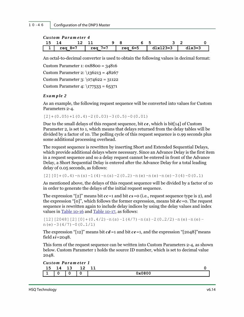
Configuration of the DNP3 Master1 0 - 4 6
HSQ Technology v6.14
Custom Parameter 4 15 14 12 11 9 8 6 5 3 2 0
An octal-to-decimal converter is used to obtain the following values in decimal format:
Custom Parameter 1: 0x8800 = 34816Custom Parameter 2: \136213 = 48267Custom Parameter 3: \074622 = 31122Custom Parameter 4: \177533 = 65371
Example 2
As an example, the following request sequence will be converted into values for Custom Parameters 2-4.
[2]+(0.05)+1(0.4)-2(0.03)-3(0.5)-0(0.01)
Due to the small delays of this request sequence, bit ce, which is bit[14] of Custom Parameter 2, is set to 1, which means that delays returned from the delay tables will be divided by a factor of 10. The polling cycle of this request sequence is 0.99 seconds plus some additional processing overhead.
The request sequence is rewritten by inserting Short and Extended Sequential Delays, which provide additional delays where necessary. Since an Advance Delay is the first item in a request sequence and so a delay request cannot be entered in front of the Advance Delay, a Short Sequential Delay is entered after the Advance Delay for a total leading delay of 0.05 seconds, as follows:
[2][0]+(0.4)-n(s)-1(4)-n(s)-2(0.2)-n(e)-n(e)-n(e)-3(4)-0(0.1)
As mentioned above, the delays of this request sequence will be divided by a factor of 10 in order to generate the delays of the initial request sequence.
The expression “[2]” means bit cc=1 and bit cs=0 (i.e., request sequence type is 2), and the expression “[0]”, which follows the former expression, means bit dc=0. The request sequence is rewritten again to include delay indices by using the delay values and index values in Table 10-16 and Table 10-17, as follows:
[12][2048][2][0]+(0.4/2)-n(s)-1(4/7)-n(s)-2(0.2/2)-n(e)-n(e)-n(e)-3(4/7)-0(0.1/1)
The expression “[12]” means bit cd=1 and bit ce=1, and the expression “[2048]”means field si=2048.
This form of the request sequence can be written into Custom Parameters 2-4, as shown below. Custom Parameter 1 holds the source ID number, which is set to decimal value 2048.
Custom Parameter 1 15 14 13 12 11 0
1 req_8=7 req_7=7 req_6=5 dlx123=3 dlx3=3
1 0 0 0 0x0800

v6.14 RTU Diagnostics User Manual
Configuring an RTU as a DNP3 Master 1 0 - 4 7
Custom Parameter 2 15 14 12 11 9 8 6 5 3 2 0
Custom Parameter 3 15 14 12 11 9 8 6 5 3 2 0
Custom Parameter 4 15 14 12 11 9 8 6 5 3 2 0
An octal-to-decimal converter is used to obtain the following values in decimal format:
Custom Parameter 1: 0xC800 = 51200Custom Parameter 2: \162621 = 58769Custom Parameter 3: \077327 = 32471Custom Parameter 4: \014707 = 6599
10.3.10.3 | Format of Custom Parameters 2-4, when cc=1 and cs=1
In cases where bit cc of Custom Parameter 2 is set to 1, the data format for requests is octal. The format of Custom Parameters 2-4 when bit cc of Custom Parameter 2 and bit cs of Custom Parameter 3 are both set to 1 (i.e., request sequence type is 3) is also the octal format, as shown in Figure 10-23. Custom Parameters 2-4 are defined so that they contain ten requests fields and five delay fields.
Custom Parameter 2 15 14 12 11 9 8 6 5 3 2 0
Custom Parameter 3 15 14 12 11 9 8 6 5 3 2 0
Custom Parameter 4 15 14 12 11 9 8 6 5 3 2 0
Figure 10-23. Format of Custom Parameters 2-4, when cc=1 and cs=1
The request fields are numbered from req_0 to req_9 and are placed at 3-bit boundaries. The requests are entered in the request sequence in ascending order of their indices, from req_0 to req_9. As described in previous sections, valid request values are from 0 to 7. Any of the requests from req_0 to req_9 can have any of the class request values from Class 0 request to Class 123 request, any of the delay request values (Short Sequential Delay or Extended Sequential Delay), or the null request, as shown in Table 10-6.
1 req_2=6 req_1=2 req_0=6 dlxA=2 dlx0=1
0 req_5=7 req_4=7 req_3=3 dlx2=2 dlx1=7
0 req_8=1 req_7=4 req_6=7 dlx123=0 dlx3=7
1 req_4 req_3 req_2 req_1 req_0
1 req_9 req_8 req_7 req_6 req_5
dc dlx3 dlx2 dlx1 dlxA dlx0

Configuration of the DNP3 Master1 0 - 4 8
HSQ Technology v6.14
The delay fields are also placed at 3-bit boundaries and represent indices used to extract delay values from delay tables, as shown in Table 10-18 below. Class Delay Index (dlx0) returns a Class 0 Delay, Class Delay Index (dlx1) returns a Class 1 Delay, and so on. The Class Delay field (dlx123) is entirely missing and so the Class 123 Delay is generated implicitly, as described later. Bit dc, which is bit[15] of Custom Parameter 4, is used together with Class Delay Indices to generate the values of class delays.

v6.14 RTU Diagnostics User Manual
Configuring an RTU as a DNP3 Master 1 0 - 4 9
As noted above, the Class Delay Index (dlx123)is missing. In this case, bit dc, which is bit[15] of Custom Parameter 4, is used to generate the values of Class 123 delay, as shown in Table 10-19.
In cases where bit cc is set to 1, the Advance Delay Index (dlxA) and bit dc, which is bit[15] of Custom Parameter 4, are used to generate the values of the Advance Delay, as shown in Table 10-17.
One or more Short Sequential Delays (dlsS) can be used anywhere in a request sequence. Consecutive Short Sequential Delays form a Short Delay Subsequence. A Short Delay Subsequence can be terminated only by a class request, by an Extended Sequential Delay, or by using all available request fields for the type of request sequence. A Short Delay Subsequence is not terminated by a null request.
In cases where the request sequence contains one or more Short Sequential Delays that are not followed by a class request, a Class 0 request is entered by default in the request sequence after the last Short Sequential Delay. In cases where the request sequence contains one or more Short Sequential Delays and one or more Extended Sequential Delays that are not followed by a class request, a Class 0 request is entered by default in the request sequence after the last sequential delay, regardless of the order of the Short Sequential Delays and Extended Sequential Delays within the request sequence.
The values of the delay produced by a Short Delay Subsequence depend on the number of Short Sequential Delays in the subsequence. The number of Short Sequential Delays in a
Table 10-18. Class j Delay when cc=1 and cs=1 (j = 0, 1, 2, 3)
dc dlxj Class j Delay [s] dc dlxj Class j Delay [s]
0 0 0 1 0 0
0 1 0.1 1 1 1
0 2 0.2 1 2 2
0 3 0.4 1 1 3 4
0 4 0.7 1 4 5
0 5 1 1 5 7
0 6 2 1 6 10
0 7 4 1 7 15
Table 10-19. Class 123 Delay when cc=1 and cs=1
dc Class 123 Delay [s]
0 Class 2 Delay
1 Class 3 Delay
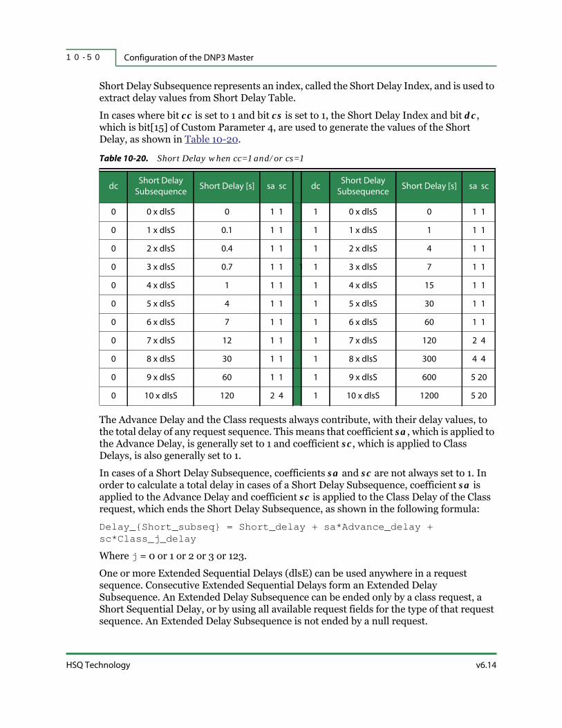
Configuration of the DNP3 Master1 0 - 5 0
HSQ Technology v6.14
Short Delay Subsequence represents an index, called the Short Delay Index, and is used to extract delay values from Short Delay Table.
In cases where bit cc is set to 1 and bit cs is set to 1, the Short Delay Index and bit dc, which is bit[15] of Custom Parameter 4, are used to generate the values of the Short Delay, as shown in Table 10-20.
The Advance Delay and the Class requests always contribute, with their delay values, to the total delay of any request sequence. This means that coefficient sa, which is applied to the Advance Delay, is generally set to 1 and coefficient sc, which is applied to Class Delays, is also generally set to 1.
In cases of a Short Delay Subsequence, coefficients sa and sc are not always set to 1. In order to calculate a total delay in cases of a Short Delay Subsequence, coefficient sa is applied to the Advance Delay and coefficient sc is applied to the Class Delay of the Class request, which ends the Short Delay Subsequence, as shown in the following formula:
Delay_{Short_subseq} = Short_delay + sa*Advance_delay + sc*Class_j_delay
Where j = 0 or 1 or 2 or 3 or 123.
One or more Extended Sequential Delays (dlsE) can be used anywhere in a request sequence. Consecutive Extended Sequential Delays form an Extended Delay Subsequence. An Extended Delay Subsequence can be ended only by a class request, a Short Sequential Delay, or by using all available request fields for the type of that request sequence. An Extended Delay Subsequence is not ended by a null request.
Table 10-20. Short Delay when cc=1 and/or cs=1
dcShort Delay
SubsequenceShort Delay [s] sa sc dc
Short Delay
SubsequenceShort Delay [s] sa sc
0 0 x dlsS 0 1 1 1 0 x dlsS 0 1 1
0 1 x dlsS 0.1 1 1 1 1 x dlsS 1 1 1
0 2 x dlsS 0.4 1 1 1 2 x dlsS 4 1 1
0 3 x dlsS 0.7 1 1 1 1 3 x dlsS 7 1 1
0 4 x dlsS 1 1 1 1 4 x dlsS 15 1 1
0 5 x dlsS 4 1 1 1 5 x dlsS 30 1 1
0 6 x dlsS 7 1 1 1 6 x dlsS 60 1 1
0 7 x dlsS 12 1 1 1 7 x dlsS 120 2 4
0 8 x dlsS 30 1 1 1 8 x dlsS 300 4 4
0 9 x dlsS 60 1 1 1 9 x dlsS 600 5 20
0 10 x dlsS 120 2 4 1 10 x dlsS 1200 5 20

v6.14 RTU Diagnostics User Manual
Configuring an RTU as a DNP3 Master 1 0 - 5 1
In cases where the request sequence contains one or more Extended Sequential Delays that are not followed by a class request, a Class 0 request is entered by default in the request sequence after the last Short Sequential Delay. Furthermore, in cases where the request sequence contains one or more Short Sequential Delays and one or more Extended Sequential Delays that are not followed by a class request, a Class 0 request is entered by default in the request sequence after the last sequential delay, regardless of the order of the Short Sequential Delays and Extended Sequential Delays within the request sequence.
The values of the delay produced by an Extended Delay Subsequence depend on the number of Extended Sequential Delays in the subsequence. The number of Extended Sequential Delays in an Extended Delay Subsequence represents an index, called the Extended Delay Index, used to extract delay values from the Extended Delay Table.
In cases where bit cc is set to 1 and bit cs is set to 1, the Extended Delay Index and bit dc, which is bit[15] of Custom Parameter 4, are used to generate the values of the Extended Delay, as shown in Table 10-21.
The Advance Delay and the class requests always contribute, with their delay values, to the total delay of any request sequence. This means that coefficient ea, which is applied to the Advance Delay, is generally set to 1 and coefficient ec, which is applied to Class delays, is also generally set to 1.
In cases of an Extended Delay Subsequence, coefficients ea and ec are not always set to 1. In order to calculate a total delay in the case of an Extended Delay Subsequence, coefficient ea is applied to the Advance Delay and coefficient ec is applied to the Class
Table 10-21. Extended Delay when cc=1 and/or cs=1
dcExtended Delay
Subsequence
Extended
Delay [s]ea ec dc
Extended Delay
Subsequence
Extended
Delay [s]ea ec
0 0 x dlsE 0 1 1 1 0 x dlsE 0 1 1
0 1 x dlsE 0.2 1 1 1 1 x dlsE 2 1 1
0 2 x dlsE 0.5 1 1 1 2 x dlsE 5 1 1
0 3 x dlsE 1 1 1 1 1 3 x dlsE 10 1 1
0 4 x dlsE 2 1 1 1 4 x dlsE 20 1 1
0 5 x dlsE 5 1 1 1 5 x dlsE 45 1 1
0 6 x dlsE 10 1 1 1 6 x dlsE 90 1 1
0 7 x dlsE 20 1 1 1 7 x dlsE 180 2 8
0 8 x dlsE 45 1 1 1 8 x dlsE 420 4 16
0 9 x dlsE 90 1 2 1 9 x dlsE 900 10 20
0 10 x dlsE 180 2 8 1 10 x dlsE 1800 20 40

Configuration of the DNP3 Master1 0 - 5 2
HSQ Technology v6.14
Delay of the Class Request, which ends the Extended Delay Subsequence, as shown by the following formula:
Delay_{Extended_subseq} = Extended_delay + ea*Advance_delay + ec*Class_j_delay
Where j = 0 or 1 or 2 or 3 or 123.
Example 1
As an example, the following request sequence will be converted into values for Custom Parameters 2-4.
[3]+(1)+1(2)-2(3)-3(5)-123(7)-0(9)
The request sequence is rewritten by inserting Short and/or Extended Sequential Delays that provide additional delays where necessary. A Class 0 request (with a Class 0 delay of four seconds) is entered by default after the last Short Sequential Delay, as follows:
[3][1]+(1)+1(2)-n(s)-2(2)-n(s)-3(4)-n(s)-n(e)-123()-n(e)-n(e)+0(4)
The expression “[3]” means bit cc=1 and bit cs=1 (i.e., request sequence type is 3), and the expression “[1]”, which follows the former expression, means bit dc=1. The expression “123()” indicates that the Class 123 request is missing its own Class 123 delay and instead receives a Class 2 delay since bit dc=0. With the additional Extended Sequential Delays, the Class 123 request has a delay of seven seconds. The request sequence is rewritten again to include delay indices by using the delay values and index values in Table 10-17, Table 10-18, and Table 10-19, as follows:
[8][2048][3][1]+(1/1)+1(2/2)-n(s)-2(2/2)-n(s)-3(4/3)-n(s)-n(e)-123()-n(e)-n(e)+0(4/3)
The expression “[8]” means bit cd=1 and the expression “[2048]”means field si=2048. This form of the request sequence can be written into Custom Parameters 2-4, as shown below. Custom Parameter 1 holds the source ID number, which is set to decimal value 2048.
Custom Parameter 1 15 14 13 12 11 0
Custom Parameter 2 15 14 12 11 9 8 6 5 3 2 0
Custom Parameter 3 15 14 12 11 9 8 6 5 3 2 0
1 0 0 0 0x0800
1 req_4=4 req_3=6 req_2=3 req_1=6 req_0=2
0 req_9=7 req_8=7 req_7=5 req_6=7 req_5=6

v6.14 RTU Diagnostics User Manual
Configuring an RTU as a DNP3 Master 1 0 - 5 3
Custom Parameter 4 15 14 12 11 9 8 6 5 3 2 0
An octal-to-decimal converter is used to obtain the following values in decimal format:
Custom Parameter 1: 0x8800 = 34816Custom Parameter 2: \146362 = 52466Custom Parameter 3: \177576 = 65406Custom Parameter 4: \132213 = 46219
Example 2
As an example, the following request sequence will be converted into values for Custom Parameters 2-4.
[3]+(0.06)+1(0.4)-2(0.03)-3(0.45)-123(0.04)-0(0.01)
Due to the small delays of this request sequence, bit ce, which is bit[14] of Custom Parameter 1, is set to 1, which means that delays returned from the delay tables will be divided by a factor of 10. The polling cycle of this request sequence is 0.99 seconds plus some additional processing overhead.
The request sequence is rewritten by inserting Short and Extended Sequential Delays, which provide additional delays where necessary. Since an Advance Delay is the first item in a request sequence and so a delay request cannot be entered in front of the Advance Delay, an Extended Sequential Delay is entered after the Advance Delay for a total leading delay of 0.06 seconds, as follows:
[12][4096][3][0]+(0.4)+n(e)-1(4)-n(s)-2(0.2)-n(e)-n(e)-3(4)-n(e)-123()-0(0.1)
The expression “[12]” means bit cd=1 and bit cc=1 and the expression “[4096]” means bit si=0. The expression “[3]” means bit cc=1 and bit cs=1 (i.e., request sequence type is 2) and the expression “[0]”, which follows the former expression, means bit dc=0. The request sequence is rewritten again to include delay indices by using the delay values and index values in Table 10-17, Table 10-18, and Table 10-19, as follows:
[12][4096][3][0]+(0.4/2)+n(e)-1(4/7)-n(s)-2(0.2/2)-n(e)-n(e)-3(4/7)-n(e)-123()-0(0.1/1)
This form of the request sequence can be written into Custom Parameters 2-4, as shown below. Custom Parameter 1 holds the source ID number, which is set to decimal value 4096.
Custom Parameter 1 15 14 13 12 11 0
1 dlx3=3 dlx2=2 dlx1=2 dlxA=1 dlx0=3
1 1 0 0 0
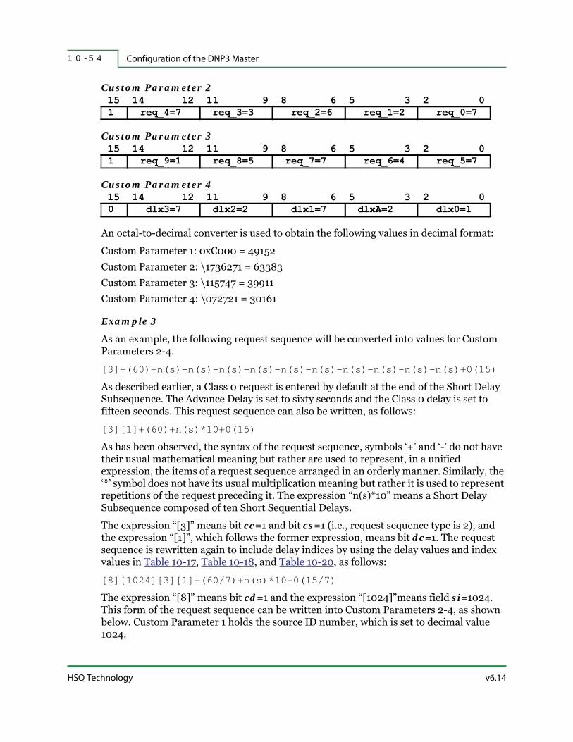
Configuration of the DNP3 Master1 0 - 5 4
HSQ Technology v6.14
Custom Parameter 2 15 14 12 11 9 8 6 5 3 2 0
Custom Parameter 3 15 14 12 11 9 8 6 5 3 2 0
Custom Parameter 4 15 14 12 11 9 8 6 5 3 2 0
An octal-to-decimal converter is used to obtain the following values in decimal format:
Custom Parameter 1: 0xC000 = 49152Custom Parameter 2: \1736271 = 63383Custom Parameter 3: \115747 = 39911Custom Parameter 4: \072721 = 30161
Example 3
As an example, the following request sequence will be converted into values for Custom Parameters 2-4.
[3]+(60)+n(s)-n(s)-n(s)-n(s)-n(s)-n(s)-n(s)-n(s)-n(s)-n(s)+0(15)
As described earlier, a Class 0 request is entered by default at the end of the Short Delay Subsequence. The Advance Delay is set to sixty seconds and the Class 0 delay is set to fifteen seconds. This request sequence can also be written, as follows:
[3][1]+(60)+n(s)*10+0(15)
As has been observed, the syntax of the request sequence, symbols ‘+’ and ‘-’ do not have their usual mathematical meaning but rather are used to represent, in a unified expression, the items of a request sequence arranged in an orderly manner. Similarly, the ‘*’ symbol does not have its usual multiplication meaning but rather it is used to represent repetitions of the request preceding it. The expression “n(s)*10” means a Short Delay Subsequence composed of ten Short Sequential Delays.
The expression “[3]” means bit cc=1 and bit cs=1 (i.e., request sequence type is 2), and the expression “[1]”, which follows the former expression, means bit dc=1. The request sequence is rewritten again to include delay indices by using the delay values and index values in Table 10-17, Table 10-18, and Table 10-20, as follows:
[8][1024][3][1]+(60/7)+n(s)*10+0(15/7)
The expression “[8]” means bit cd=1 and the expression “[1024]”means field si=1024. This form of the request sequence can be written into Custom Parameters 2-4, as shown below. Custom Parameter 1 holds the source ID number, which is set to decimal value 1024.
1 req_4=7 req_3=3 req_2=6 req_1=2 req_0=7
1 req_9=1 req_8=5 req_7=7 req_6=4 req_5=7
0 dlx3=7 dlx2=2 dlx1=7 dlxA=2 dlx0=1

v6.14 RTU Diagnostics User Manual
Configuring an RTU as a DNP3 Master 1 0 - 5 5
Custom Parameter 1 15 14 13 12 11 0
Custom Parameter 2 15 14 12 11 9 8 6 5 3 2 0
Custom Parameter 3 15 14 12 11 9 8 6 5 3 2 0
Custom Parameter 4 15 14 12 11 9 8 6 5 3 2 0
An octal-to-decimal converter is used to obtain the following values in decimal format:
Custom Parameter 1: 0x8400 = 33792Custom Parameter 2: \166666 = 60854Custom Parameter 3: \166666 = 60854Custom Parameter 4: \100077 = 32831The polling cycle of a request sequence is given by the total delay of that request sequence. In cases of this Short Delay Subsequence, the total delay is given by the following format:
Delay_{Short_subseq} = Short_delay + sa*Advance_delay + sc*Class_0_delay
Delay_{Short_subseq} = 1200 + 5*60 + 20*15 = 1800 sec = 30 min = 1/2 hour
Example 4
As an example, the following request sequence, which has the highest polling cycle, will be converted into values for Custom Parameters 2-4.
[3]+(60)+n(e)-n(e)-n(e)-n(e)-n(e)-n(e)-n(e)-n(e)-n(e)-n(e)+0(15)
As described earlier, a Class 0 request is entered by default at the end of the Extended Delay Subsequence. The Advance delay is set to sixty seconds and the Class 0 delay is set to fifteen seconds. This request sequence can also be written, as follows:
[3][1]+(60)+n(e)*10+0(15)
The expression “[3]” means bit cc=1 and bit cs=1 (i.e., request sequence type is 2) and the expression “[1]”, which follows the former expression, means bit dc=1. The request sequence is rewritten again to include delay indices by using the delay values and index values in Table 10-17, Table 10-18, and Table 10-21 as follows:
[8][1024][3][1]+(60/7)+n(e)*10+0(15/7)
1 1 0 0 0x0400
1 req_4=6 req_3=6 req_2=6 req_1=6 req_0=6
1 req_9=6 req_8=6 req_7=6 req_6=6 req_5=6
0 dlx3=0 dlx2=0 dlx1=0 dlxA=7 dlx0=7
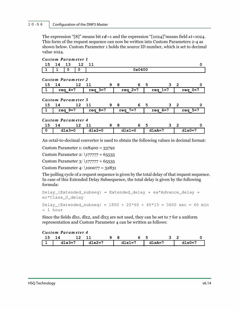
Configuration of the DNP3 Master1 0 - 5 6
HSQ Technology v6.14
The expression “[8]” means bit cd=1 and the expression “[1024]”means field si=1024. This form of the request sequence can now be written into Custom Parameters 2-4 as shown below. Custom Parameter 1 holds the source ID number, which is set to decimal value 1024.
Custom Parameter 1 15 14 13 12 11 0
Custom Parameter 2 15 14 12 11 9 8 6 5 3 2 0
Custom Parameter 3 15 14 12 11 9 8 6 5 3 2 0
Custom Parameter 4 15 14 12 11 9 8 6 5 3 2 0
An octal-to-decimal converter is used to obtain the following values in decimal format:
Custom Parameter 1: 0x8400 = 33792Custom Parameter 2: \177777 = 65535Custom Parameter 3: \177777 = 65535Custom Parameter 4: \100077 = 32831The polling cycle of a request sequence is given by the total delay of that request sequence. In case of this Extended Delay Subsequence, the total delay is given by the following formula:
Delay_{Extended_subseq} = Extended_delay + ea*Advance_delay + ec*Class_0_delay
Delay_{Extended_subseq} = 1800 + 20*60 + 40*15 = 3600 sec = 60 min = 1 hour
Since the fields dlx1, dlx2, and dlx3 are not used, they can be set to 7 for a uniform representation and Custom Parameter 4 can be written as follows:
Custom Parameter 4 15 14 12 11 9 8 6 5 3 2 0
1 1 0 0 0x0400
1 req_4=7 req_3=7 req_2=7 req_1=7 req_0=7
1 req_9=7 req_8=7 req_7=7 req_6=7 req_5=7
0 dlx3=0 dlx2=0 dlx1=0 dlxA=7 dlx0=7
1 dlx3=7 dlx2=7 dlx1=7 dlxA=7 dlx0=7

v6.14 RTU Diagnostics User Manual
Configuring an RTU as a DNP3 Master 1 0 - 5 7
This simplification provides the following values in decimal format:
Custom Parameter 1: 0x8400 = 33792Custom Parameter 2: \177777 = 65535Custom Parameter 3: \177777 = 65535Custom Parameter 4: \177777 = 65535This means that a polling cycle of one hour for a Class 0 request can be obtained in cases when, for simplification, all of the bits in Custom Parameters 2-4 are set to 1.
In cases where the Advance Delay and Class 0 Delay are both set to zero, the request sequence can be written as follows:
[8][1024][3][1]+(0/0)+n(e)*10+0(0/0)
The total delay of this request sequence is calculated by the following formula:
Delay_{Extended_subseq} = 1800 + 20*0 + 40*0 = 1800 sec = 30 min = 1/2 hour
In this case, Custom Parameter 4 can be written as follows:
Custom Parameter 4 15 14 12 11 9 8 6 5 3 2 0
This change provides the following values in decimal format:
Custom Parameter 1: 0x8400 = 33792Custom Parameter 2: \177777 = 65535Custom Parameter 3: \177777 = 65535Custom Parameter 4: \100000 = 32768
Example 5
As an example, Short and/or Extended Sequential Delays and/or Delay Subsequences are used to provide various delays, as shown in Table 10-22. Delay values are in seconds, which means that bit cc, which is bit[14] of Custom Parameter 1, is set to 0.
1 dlx3=0 dlx2=0 dlx1=0 dlxA=0 dlx0=0
Table 10-22. Short and/or Extended Sequential Delays and/or Delay Subsequence
Sequential Delay or Delay Subsequence Delay[s]
- - - 0
n(s) 1
n(e) 2
n(s)-n(e); n(e)-n(s) 3
n(s)-n(s) 4
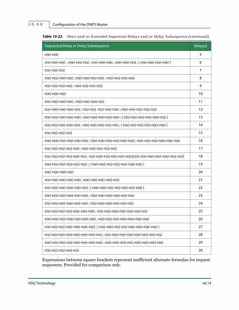
Configuration of the DNP3 Master1 0 - 5 8
HSQ Technology v6.14
Expressions between square brackets represent inefficient alternate formulas for request sequences. Provided for comparison only.
n(e)-n(e) 5
n(s)-n(s)-n(e) ; n(e)-n(s)-n(s) ; n(s)-n(e)-n(e) ; n(e)-n(e)-n(s) ; [ n(s)-n(e)-n(s)-n(e) ] 6
n(s)-n(s)-n(s) 7
n(e)-n(s)-n(e)-n(e) ; n(e)-n(e)-n(s)-n(e) ; n(e)-n(s)-n(s)-n(e) 8
n(s)-n(s)-n(s)-n(e) ; n(e)-n(s)-n(s)-n(s) 9
n(e)-n(e)-n(e) 10
n(s)-n(e)-n(e)-n(e) ; n(e)-n(e)-n(e)-n(s) 11
n(s)-n(e)-n(e)-n(e)-n(s) ; n(s)-n(s)- n(s)-n(e)-n(e) ; n(e)-n(e)-n(s)-n(s)-n(s) 12
n(e)-n(s)-n(e)-n(e)-n(e) ; n(e)-n(e)-n(e)-n(s)-n(e) ; [ n(s)-n(s)-n(s)-n(e)-n(e)-n(s) ] 13
n(s)-n(s)-n(e)-n(e)-n(e) ; n(e)-n(e)-n(e)-n(s)-n(s) ; [ n(e)-n(s)-n(s) n(s)-n(e)-n(e) ] 14
n(s)-n(s)-n(s)-n(s) 15
n(e)-n(e)-n(s)-n(e)-n(e)-n(e) ; n(e)-n(e)-n(e)-n(s)-n(e)-n(e) ; n(e)-n(s)-n(s)-n(e)-n(e)-n(e) 16
n(s)-n(s)-n(s)-n(s)-n(e) ; n(e)-n(s)-n(s)-n(s)-n(s) 17
n(s)-n(s)-n(s)-n(s)-n(e)-n(s) ; n(s)-n(e)-n(s)-n(s)-n(s)-n(s);[n(s)-n(s)-n(e)-n(e)-n(e)-n(s)-n(s)] 18
n(e)-n(s)-n(s)-n(s)-n(s)-n(e) ; [ n(e)-n(e)-n(s)-n(s)-n(e)-n(e)-n(e) ] 19
n(e)-n(e)-n(e)-n(e) 20
n(s)-n(e)-n(e)-n(e)-n(e) ; n(e)-n(e)-n(e)-n(e)-n(s) 21
n(s)-n(e)-n(e)-n(e)-n(e)-n(s) ; [ n(e)-n(e)-n(s)-n(s)-n(s)-n(s)-n(e) ] 22
n(e)-n(s)-n(e)-n(e)-n(e)-n(e) ; n(e)-n(e)-n(e)-n(e)-n(s)-n(e) 23
n(s)-n(s)-n(e)-n(e)-n(e)-n(e) ; n(e)-n(e)-n(e)-n(e)-n(s)-n(s) 24
n(s)-n(s)-n(s)-n(s)-n(e)-n(e)-n(e) ; n(s)-n(e)-n(e)-n(e)-n(e)-n(s)-n(s) 25
n(e)-n(e)-n(s)-n(e)-n(e)-n(e)-n(e) ; n(e)-n(s)-n(s)-n(e)-n(e)-n(e)-n(e) 26
n(s)-n(s)-n(s)-n(e)-n(e)-n(e)-n(e) ; [ n(s)-n(e)-n(s)-n(s)-n(e)-n(e)-n(e)-n(e) ] 27
n(s)-n(s)-n(s)-n(e)-n(e)-n(e)-n(e)-n(s) ; n(s)-n(e)-n(e)-n(e)-n(e)-n(s)-n(s)-n(s) 28
n(e)-n(s)-n(s)-n(s)-n(e)-n(e)-n(e)-n(e) ; n(e)-n(e)-n(s)-n(s)-n(e)-n(e)-n(e)-n(e) 29
n(s)-n(s)-n(s)-n(s)-n(s) 30
Table 10-22. Short and/or Extended Sequential Delays and/or Delay Subsequence (continued)
Sequential Delay or Delay Subsequence Delay[s]

A - 1v6.14 RTU Diagnostics User Manual
A P P E N D I X A
RTUDIAG ON A MISER HOST
RTUDiag is designed to run as a stand-alone program on a Windows-based PC. However, sometimes it is useful to be able to do RTUDiag type functions from the Host. Therefore, RTUDiag was ported over to run on MISER Host systems. This appendix describes:
Overview
Screen Differences
Keyboard Differences
Command Differences
RTUDiag Settings
NCC Issues

OverviewA - 2
HSQ Technology v6.14
A.1 | Overview
The advantages of running RTUDiag on a MISER Host system are:
Stand-alone RTUDiag typically requires you to physically access the RTU site. This can be inconvenient, impractical, or impossible.
Sometimes a technician is present at an RTU site to fix a problem but does not have a laptop or the RTUDiag program. In these cases, the technician can request assistance from the central system operators via RTUDiag running on the MISER Host system.
Sometimes a technician is present at an RTU site to fix a problem but is not sufficiently qualified or trained in RTUDiag operation. In these cases, the central system operators can run RTUDiag on the MISER Host system to perform the required operations on behalf of the technician.
FYI: RTUDiag was written to run on a stand-alone PC. This is a very different environment from a MISER Host system. Some adjustments were necessary.
A.1.1 | Prerequisites
RTUDiag must be running. To start it, open a DECterm and type RTUDIAG at the MISER prompt.
A MISER Host system communicating with HSQ RTUs running v1_1, 1_2, 1_3, 1_4, 1_5, 1_6, and v8 RTU software. (A limited set of RTUDiag commands may even work with RTUs that are not on this list, but no guarantees are made.)
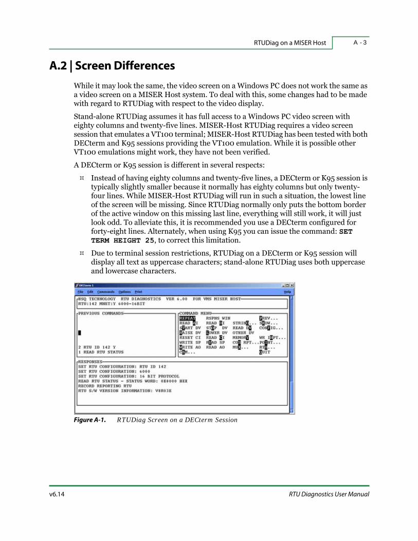
v6.14 RTU Diagnostics User Manual
RTUDiag on a MISER Host A - 3
A.2 | Screen Differences
While it may look the same, the video screen on a Windows PC does not work the same as a video screen on a MISER Host system. To deal with this, some changes had to be made with regard to RTUDiag with respect to the video display.
Stand-alone RTUDiag assumes it has full access to a Windows PC video screen with eighty columns and twenty-five lines. MISER-Host RTUDiag requires a video screen session that emulates a VT100 terminal; MISER-Host RTUDiag has been tested with both DECterm and K95 sessions providing the VT100 emulation. While it is possible other VT100 emulations might work, they have not been verified.
A DECterm or K95 session is different in several respects:
Instead of having eighty columns and twenty-five lines, a DECterm or K95 session is typically slightly smaller because it normally has eighty columns but only twenty-four lines. While MISER-Host RTUDiag will run in such a situation, the lowest line of the screen will be missing. Since RTUDiag normally only puts the bottom border of the active window on this missing last line, everything will still work, it will just look odd. To alleviate this, it is recommended you use a DECterm configured for forty-eight lines. Alternately, when using K95 you can issue the command: SET TERM HEIGHT 25, to correct this limitation.
Due to terminal session restrictions, RTUDiag on a DECterm or K95 session will display all text as uppercase characters; stand-alone RTUDiag uses both uppercase and lowercase characters.
Figure A-1. RTUDiag Screen on a DECterm Session

HSQ Technology v6.14
Keyboard DifferencesA - 4
Figure A-2. RTUDiag Screen on a K95 Session
A.3 | Keyboard Differences
While it may look the same, the keyboard on a Windows PC does not work the same as a keyboard on a MISER Host system. To deal with this, some changes must be made with regard to keyboard entries.
Stand-alone RTUDiag assumes it has full access to a PC type keyboard. A VT100 terminal (or a DECterm or K95 session) does not have all the same keys available, and some of those keys, while available, don't work the same way. Use the table below for available keyboard options:
Table A-1. Keyboard Options
Stand-Alone RTUDiag RTUDiag on DECterm RTUDiag on K95 Explanation
<Esc> ! or ` ! or `
Substitute the exclamation
point (!) or the grave accent
(`) instead of the <Esc> key
when on a MISER Host.
<Alt> ~ or @ ~ or @
<Alt> keys are performed
as a two-character
sequence. Press the tilde
(~) or at sign (@) followed
by the desired key (e.g., to
enter <Alt-R>, type <~ r>).
<Ins><Ins> (<Insert>) on
numeric keypad.
<Ins> on numeric
keypad.

v6.14 RTU Diagnostics User Manual
RTUDiag on a MISER Host A - 5
FYI: The tilde (~) character is typically used as a preamble to simulate the <Alt> key. If you want to include a tilde character in your MISER-Host RTUDiag data input, then type a double tilde (~~). The same applies for the ‘at’ sign (@@).
Required: In the RTUDiag environment on MISER, the numeric keypad (on the right side of the keyboard) does NOT produce numbers. You must use the numeric keys on the top row of the keyboard for inputting numeric characters.
A.4 | Command Differences
Stand-alone RTUDiag works on the principle that the program builds a frame for transmission to the RTU. This frame can contain zero, one, or more command packets for the RTU to process. The MISER Host environment does not allow any such frame-building interface. Instead, all MISER Host programs (MISER-Host RTUDiag included) are limited to passing a single command packet to the MISER system, which gets routed via the MISER NCC programs to the proper RTU. As a result, a few RTUDiag command options are not meaningful in the MISER Host environment and these command options have been removed from the MISER-Host RTUDiag menus.
Since MISER-Host RTUDiag needs to pass individual command packets one at a time via the NCC to the RTU, it will obviously run slower than stand-alone RTUDiag for any given operation.
<Del>
<Del> (<Delete>) on
the numeric keypad
or <Del> in the six-
key grouping to the
left of the numeric
keypad.
<Del> on the
numeric keypad.
<Backspace><Backspace> or
<Ctrl-h>.
<Backspace> or
<Ctrl-h>.
On a MISER Host both
<Backspace> and <Ctrl-h>
work the same way.
<F1> through <F4> <F1> through <F4> <F1> through <F4><F1> through <F4> work
the same in all cases.
<F5> through <F12> N/A N/A
The <F5> through <F12>
keys don’t work correctly in
a DECterm or in a K95
sessions.
Table A-1. Keyboard Options (continued)
Stand-Alone RTUDiag RTUDiag on DECterm RTUDiag on K95 Explanation

RTUDiag SettingsA - 6
HSQ Technology v6.14
A.5 | RTUDiag Settings
When running MISER-Host RTUDiag you still need to set the following configurations to ensure things work properly. These are set the same as they are for stand-alone RTUDiag (refer to “RTU Settings” on page 3-3).
Config… > RTU Settings… > RTU ID
Config… > RTU Settings… > RTU Type
You still need to set the communications protocol to HSQ 8-bit or HSQ 16-bit, according to the RTU you want to work with.
A.6 | NCC Issues
MISER-Host RTUDiag needs to route all command packets via the MISER NCC programs to the proper RTU. The MISER NCC programs have some limitations on the types and sizes of packets they can route. A few of the RTUDiag command options use command packets that fall outside these limitations. In those cases, the RTUDiag command times out. Some NCC programs handle this better than others, depending on the exact NCC version. Generally, MISER Host system version 6.13 (or later) will work reasonably well with Host RTUDiag. Prior MISER Host systems will have problems doing anything beyond the most basic RTUDiag operations.

B - 1v6.14 RTU Diagnostics User Manual
A P P E N D I X B
SPECIAL DIAGNOSTICS MODES
This appendix is applicable to the 25x86 RTU. In addition to running the normal RTU software, it can also operate in a Special Diagnostics Mode.

25x86 Special Diagnostics ModeB - 2
HSQ Technology v6.14
B.1 | 25x86 Special Diagnostics Mode
The following is necessary:
A laptop PC configured with:
MS-DOS (or Windows)
Kermit Software (included in the RTUDIAG installation directory, e.g., C:\RTU\KERMIT)
Standard test set cable
A 25x86 RTU with one of the following:
Advantech PCA 6134P CPU board
Advantech PCA 6135L CPU board
Advantech PCM 3343F CPU board
Advantech PCM 3343L CPU board
Advantech PCM 4862 CPU board
Advantech PCM 9579F CPU board
Advantech PCM 9588 CPU board
RTU Software (optional)
B.1.1 | Setup
These steps must be done before attempting any of the following procedures.
1. Power down the RTU.
2. Connect the test set cable between Port 2 of the RTU and the appropriate COM port on the laptop.– or –Connect an Ethernet cable between the laptop and the RTU.
FYI: If you are directly connecting the two (not through a switch) you must use an Ethernet crossover cable and configure the LAN port on the laptop to be on the same subnet as the RTU. Consult with your Network Administrator if you need assistance.

v6.14 RTU Diagnostics User Manual
Special Diagnostics Modes B - 3
Figure B-1. 25x86 RTU
3. Make a note of the RTU ID switch settings. This is important, you will need to set the ID back when you are finished.
4. Set the RTU ID to 0-0-0 or 9-9-9 (depending on the RTU software version, see “Options 0-0-0 and 9-9-9” on page C-2). Refer to “RTU System Information” on page 1-6 for details on setting the RTU ID.
5. Set the Stand Alone Switch to the Auto (center) position.
6. Power on the RTU.
7. Wait at least sixty seconds after the first beep (there may or may not be a second audible beep) for the RTU to begin operation in diagnostic mode.
FYI: You must wait the required amount of time; if not, the RTU will not go into diagnostic mode and you will not be able to do any of the diagnostic functions properly.
Warning: Using 9-9-9 will wipe out all stored info on the RTU. This will delete all configuration info, all stored VCL algorithm files, all stored control blocks, all stored network configuration info, all log files, and all stored fatal error information files.

25x86 Special Diagnostics ModeB - 4
HSQ Technology v6.14
Table B-1. Special Diagnostics Mode Options
RTU ID Switch Setting Function
0-0-0 No longer supported as of R12b RTU software, replaced by 9-9-9.
0-0-1 Runs a Kermit server on RTU port 2 at 9600 bps.
0-0-2Gives an MS-DOS prompt on RTU port 2 at 9600 baud. This option is
recommended for technically skilled users only.
0-0-3Runs stand-alone TFTP server software on the RTU. This option is
recommended for technically skilled users only.
0-0-5 Runs a Kermit server on RTU port 1 at 38400 bps.
0-0-6 Runs a Kermit server on RTU port 2 at 38400 bps.
0-0-7 Runs a Kermit server on RTU port 3 at 38400 bps.
0-0-8 Runs a Kermit server on RTU port 4 at 38400 bps.
0-0-9 Runs a Kermit server over Ethernet.
9-1-1
Starts the RTU in “minimum” mode. That is, NEWRTU.EXE is started with
both the “-minimum” and “-ignoreidswitches” command line option. This
allows you to boot the RTU so that it will communicate with the Host but do
nothing more. It is then possible for HSQ technical support personnel to
transfer files onto and off of the RTU to correct any problems that may have
been introduced. Supported file transfer methods are TFTP, RTX, and
Kermit.
9-8-8Attempts to go back to a previous version of the Point Map. This is useful if
an RTU gets a new Point Map downloaded to it, but then does not work.
9-8-9Attempts to go back to a previous version of NEWRTU.EXE. This is useful
if an RTU gets an upgraded NEWRTU.EXE file, but then does not work.
9-9-5 Deletes all stored VCL algorithm files in the RTU.
9-9-6 Deletes all stored control blocks in the RTU.
9-9-7Deletes point definitions in the RTU. This option is useful if you want to
wipe out a damaged point definition file.
9-9-8Deletes the Point Map in the RTU. This option is useful if you want to wipe
out the Point Map and start from scratch for whatever reason.
9-9-9
USE WITH CAUTION! This resets the RTU to factory settings. Basically, this
allows you to start over with a blank slate, and is therefore useful when
moving a stack from one location to another where a complete
reconfiguration will be done.

v6.14 RTU Diagnostics User Manual
Special Diagnostics Modes B - 5
B.1.2 | Upgrading the 25x86 RTU Software Via COM2
1. Set the Rotary Address Switches to 0-0-1.
2. Toggle the Stand Alone Switch from AUTO to FORCED (left position), and then back to AUTO. This will start a Kermit Server on the RTU.
FYI: When you switch between “STAND ALONE” and “FORCED” you should hear a pair of beeps going from a low frequency to a higher frequency and back. This indicates the desired diagnostic operation is in progress.
3. Once the Kermit server on the RTU is started, the RTS LED on Port 2 will light. If the RTS LED does not illuminate, verify the following:
The reboot wait-interval during RTU setup was at least thirty seconds after Power On.
The RTU flat ribbon cable between the HSQ 2572 board and the RTU is connected properly.
The RTU has not experienced a hardware or software failure. In the case of a hardware or software failure, this procedure cannot be used.
4. Open a command window on the laptop. (If your laptop is running Windows, refer to “Software Installation” on page 1-3 to learn how to do this.)
5. Start the Kermit utility program on the laptop and type the following Kermit commands in the order listed. This will configure Kermit on the laptop to operate in the required mode.SET PORT COM1 (or COM2, depending on your laptop configuration)SET SPEED 9600SET FILE TYPE BINARYSET SEND PACKET 2000SET RECEIVE PACKET 2000The command SET FILE TYPE BINARY ensures that the data transfer is done in a binary format. If this command is not typed, the procedure will appear to finish, but the transfer of data will not be done properly and the RTU will not receive the correct data.
Best Practices: For convenience, these commands may be placed in the file MSCUSTOM.INI on your laptop. This causes automatic execution every time Kermit is started.

25x86 Special Diagnostics ModeB - 6
HSQ Technology v6.14
6. The laptop is now configured to execute remote Kermit commands. To view the directory of the files on the RTU, at the prompt type:REMOTE DIR
This will display the files, along with their date and size, that are currently in the RTU non-volatile memory. This confirms that the Kermit connection is functioning.If the file directory is not displayed, then verify that the previous steps have been performed properly.
7. Delete the executable code file, NEWRTU.EXE by typing:REMOTE DEL NEWRTU.EXE
8. Confirm that the file NEWRTU.EXE is no longer present on the RTU by typing:REMOTE DIR
If NEWRTU.EXE is still present, then an error has occurred during the remote delete process. Ensure there were no typing errors (if there was, repeat the remote delete step). If the file still cannot be deleted, it may be the non-volatile memory is write-protected, in which case this procedure cannot be used.
9. Transfer the new NEWRTU.EXE file to the RTU. The new executable program file must be in the current, working RTU directory (e.g., C:\RTU) type:SEND NEWRTU.EXE
This transfers the new RTU executable code to the RTU. This process will take several minutes, during which time a progress bar is displayed. While the transfer is happening, Kermit will display the remote filename near the bottom of the screen:Last Message: Remote name is. \NEWRTU.EXE
If the remote name displayed is not NEWRTU.EXE, then NEWRTU.EXE was not properly deleted from the RTU (Step 7).Kermit will also display the type of transfer near the top of the screen:File type: BINARY
If the file transfer mode is not shown as binary, then Kermit was not configured correctly (Step 5).When the transfer is complete, type:FINISH
This will close the Kermit Session on the RTU.10. To exit Kermit on the Laptop, type:
EXIT
B.1.3 | Alternately Upgrading the 25x86 RTU Software Via COM2
By setting the Rotary Address Switches to 0-0-6, the RTU will run Kermit using COM2 at a speed of 38400 baud. Otherwise, the steps are the same as “Upgrading the 25x86 RTU Software Via COM2”.

v6.14 RTU Diagnostics User Manual
Special Diagnostics Modes B - 7
B.1.4 | Upgrading the 25x86 RTU Software Via COM1
By setting the Rotary Address Switches to 0-0-5, the RTU will run Kermit using COM1 at a speed of 38400 baud. Otherwise, the steps are the same as “Upgrading the 25x86 RTU Software Via COM2”.
B.1.5 | Upgrading the 25x86 RTU Software Via COM3
By setting the Rotary Address Switches to 0-0-7, the RTU will run Kermit using COM3 at a speed of 38400 baud. Otherwise, the steps are the same as “Upgrading the 25x86 RTU Software Via COM2”.
B.1.6 | Upgrading the 25x86 RTU Software Via COM4
By setting the Rotary Address Switches to 0-0-8, the RTU will run Kermit using COM4 at a speed of 38400 baud. Otherwise, the steps are the same as “Upgrading the 25x86 RTU Software Via COM2”.
B.1.7 | Upgrading the 25x86 RTU Software Via Ethernet
By setting the Rotary Address Switches to 0-0-9, the RTU will run Kermit using an Ethernet port. Otherwise, the steps are the same as “Upgrading the 25x86 RTU Software Via COM2”.
B.1.8 | Clearing the 25x86 RTU Configuration
Normally the RTU stores its configuration settings in a file named EEPROM.RTU. If this file is present, then the RTU uses it. If it is missing, then a new blank one is created during the initial RTU boot-up process.
Warning: Performing this procedure will delete ALL current RTU Configuration settings. Proceed with caution.
1. Verify that the Rotary Address Switches are set to 0-0-0.
2. Toggle the Stand Alone Switch from AUTO to FORCED (left position), and then back to AUTO. This will delete the current version of the EEPROM file and delete all of the current RTU configuration settings.
B.1.9 | Running MS-DOS on the 25x86 RTU
Simple MS-DOS commands can be run on the 25x86 RTU and the results displayed on your laptop screen. To run the RTU in MS-DOS mode:

25x86 Special Diagnostics ModeB - 8
HSQ Technology v6.14
1. Start Kermit as previously described, at the prompt type:CONNECT
2. Set the Rotary Address Switches to 0-0-2.
3. Toggle the Stand Alone Switch from AUTO to FORCED (left position), and then back to AUTO. This will start MS-DOS on the RTU.An MS-DOS welcome message and prompt will display. The MS-DOS commands (COPY, DEL, REN, TYPE, etc.) are now available for use.
4. When finished, type:EXIT
Press <Alt-x> to restore the Kermit prompt.
B.1.10 | Exiting Special Diagnostic Mode
Once you are finished using the Special Diagnostics Mode, return the RTU to normal operation:
1. Set the RTU power switch to the OFF position.
2. Set the RTU ID Rotary Address Switches back to their original settings.
3. Put the Stand Alone Switch in its correct position (typically AUTO).
4. Put the Outputs Enabled switch into its correct position (typically ENABLED).
5. Restore power to the RTU.
C - 1v6.14 RTU Diagnostics User Manual
A P P E N D I X C
VERSION NOTES
C.1 | Version 1.4 Notes
The RTU makes a chirping sound when a successful Ethernet connection is made. The sound consists of one lower-pitched tone for reception and one higher-pitched note for reply.
The RTU makes a buzzing sound while the Solid State Disk (SSD) is being accessed. This is normal, do not turn off or reset the RTU. You can expect to hear this sound when:
The RTU is first started.
A successful configuration is completed.
A Point Map is downloaded.
C.2 | Version 1.5 Notes
RTU Diagnostics version 1.5 added some new Special Diagnostics Mode options.
C.2.1 | Restrictions
All 25x86 RTUs shipped from the factory loaded with R12b software or later, support all of the Special Diagnostics Mode options shown below.

Version 8 Special Diagnostics ModeC - 2
HSQ Technology v6.14
FYI: Unlike normal RTU operational features, Special Diagnostics Mode options are not a part of the file NEWRTU.EXE. They are instead a function of a variety of files bundled with a given software release. Since RTU software is typically field-upgraded only by downloading the NEWRTU.EXE file, RTUs that have been field-upgraded to R12b or later may or may not support all of the Special Diagnostics Mode options shown below. However, you can get some clues as to which Special Diagnostic Mode options might be available by the use of the RDR command on the Host. List the directory for the RTU and look for files with names like DIAnnn.BAT (where “nnn” is a three-digit number). The presence of these files gives an indication of what three-digit Special Diagnostics Mode options are available on that RTU.
25x86 RTUs that were shipped from the factory equipped with R12a software or earlier are guaranteed to support Special Diagnostics Mode options 0-0-1 and 0-0-2. However, there is a strong probability they may also offer other options as well, though this is not assured.
C.2.1.1 | Options 0-0-0 and 9-9-9
Options 0-0-0 and 9-9-9 are both used to reset the RTU to its factory settings. Initially, only 0-0-0 was used for this purpose, but it was determined that 0-0-0 was too easy to do by accident and it was changed to 9-9-9 as a safety measure. The following rule applies:
RTUs factory-equipped with version R12a or earlier software use option 0-0-0 for this purpose.
RTUs factory-equipped with R12b or later software use option 9-9-9 for this purpose.
C.3 | Version 8 Special Diagnostics Mode
Version 8 supports new Special Diagnostic Mode options in addition to those compiled in Table B-1 on page B-4.
Table C-1. Special Diagnostics Mode Options
RTU ID Switch Setting Function
0-1-5 Runs a Kermit server on RTU port 1 at 115200 bps.
0-1-6 Runs a Kermit server on RTU port 2 at 115200 bps.
0-1-7 Runs a Kermit server on RTU port 3 at 115200 bps.
0-1-8 Runs a Kermit server on RTU port 4 at 115200 bps.
9-9-3 Deletes all modem configuration data.
9-9-4 Deletes all LOG files.

v6.14 RTU Diagnostics User Manual
Version Notes C - 3
C.4 | Custom Parameter 7
This parameter setting is only applicable for 6000 RTUs.
This allows the use of a DI to emulate the Stand Alone switch of a 25x86 RTU. The specified DI will indicate a request for STAND ALONE INHIBIT if the DI is ON or STAND ALONE AUTO if the DI is OFF.
C.4.1 | Setting
An AUX DI can use ID addresses in the range of 225-256. The recommended DI address is 250 (twenty-sixth AUX DI).
C.5 | Custom Parameter 8
In extremely hostile electrical environments, this setting provides an extra level of redundancy to prevent unwanted device operation. When Custom_Param_8 is enabled, it adds pulsing of an optional DV to operate a safety relay that activates for any Start DV or Stop DV command targeted at a “momentary” DV point. The safety relay is not activated for a Start DV or Stop DV command targeted at a “maintained” DV point. Additionally, this pulsing of the optional DV also occurs for Raise DV and Lower DV commands, regardless of whether the DV point is momentary or maintained.
The normally open contacts of the safety relay can supply field power to DO boards, which are then disabled when the safety relay is deenergized.
C.5.1 | Setting
To enable this safety relay feature, specify the DV number for the safety relay by placing a non-zero DV number in the Custom_Param_8 setting. If Custom_Param_8 is set to zero, the safety relay logic is disabled, allowing for standard behavior and permitting the RTU to be used at a site with ordinary DV points.
C.6 | Custom Parameter 10
Some RTU configuration specifics can be set via RTUDiag and its Custom_Param_10 feature. This is a 16-bit word with each individual bit enabling or disabling a specific feature. To determine the proper value, go down the list and decide which of the features below you want. Once you have selected them, add up the numeric codes for each of the features and use this is as the value for Custom_Param_10. For example, if you want “enable quiet operation (no sounds)” and “turn off messages to video screen”, then use 5 as the value (1 + 4). A common setting is “enable basic error reporting COS to Host” and “enable ASCII (text-based) error reporting COS to Host” (2 + 512 = 514).
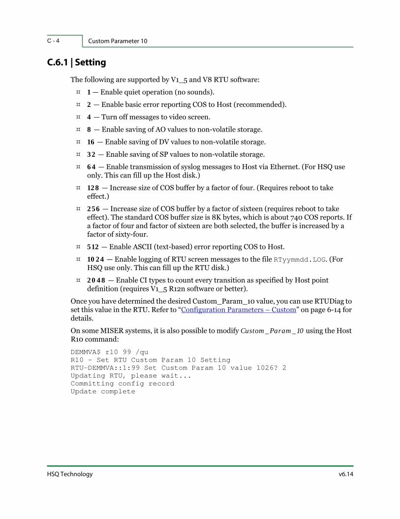
Custom Parameter 10C - 4
HSQ Technology v6.14
C.6.1 | Setting
The following are supported by V1_5 and V8 RTU software:
1 — Enable quiet operation (no sounds).
2 — Enable basic error reporting COS to Host (recommended).
4 — Turn off messages to video screen.
8 — Enable saving of AO values to non-volatile storage.
16 — Enable saving of DV values to non-volatile storage.
32 — Enable saving of SP values to non-volatile storage.
64 — Enable transmission of syslog messages to Host via Ethernet. (For HSQ use only. This can fill up the Host disk.)
128 — Increase size of COS buffer by a factor of four. (Requires reboot to take effect.)
256 — Increase size of COS buffer by a factor of sixteen (requires reboot to take effect). The standard COS buffer size is 8K bytes, which is about 740 COS reports. If a factor of four and factor of sixteen are both selected, the buffer is increased by a factor of sixty-four.
512 — Enable ASCII (text-based) error reporting COS to Host.
1024 — Enable logging of RTU screen messages to the file RTyymmdd.LOG. (For HSQ use only. This can fill up the RTU disk.)
2048 — Enable CI types to count every transition as specified by Host point definition (requires V1_5 R12n software or better).
Once you have determined the desired Custom_Param_10 value, you can use RTUDiag to set this value in the RTU. Refer to “Configuration Parameters – Custom” on page 6-14 for details.
On some MISER systems, it is also possible to modify Custom_Param_10 using the Host R10 command:
DEMMVA$ r10 99 /quR10 - Set RTU Custom Param 10 SettingRTU-DEMMVA::1:99 Set Custom Param 10 value 1026? 2Updating RTU, please wait...Committing config recordUpdate complete

D - 1v6.14 RTU Diagnostics User Manual
A P P E N D I X D
MODBUS MESSAGE FORMATS
This appendix contains examples that show the format of query and response messages between the RTU Master and Modbus Slave device. This appendix describes:
Read Examples
Write Examples
Exception Responses (Error Codes)

Read ExamplesD - 2
HSQ Technology v6.14
D.1 | Read Examples
D.1.1 | Read Coil Status
Function Code 1 reads the ON/OFF status of discrete coils in the Slave. Broadcast is not supported. The maximum parameters can vary dependent on the Modbus Slave. The query message specifies the starting coil and quantity of coils to be read. Coils are addressed starting at zero (i.e., coils 1-16 are addressed as 0-15).
Here is an example requesting the ON/OFF status of discrete coils #20 to 56 from the Slave device with address 17 (11 01 0013 0025 0E84):
Here is an example of the response (11 01 05 CD6BB20E1B 45E6):
The more significant bits contain the higher coil variables. This shows that coil 36 is OFF (0) and 43 is ON (1). Due to the number of coils requested, the last data field contains the status of only five coils.
Field Name Example
Slave Address 11 (17 = 11 hex)
Function Code 01 (Read Coil Status)
Data Address of First Coil 0013 (Coil 20 − 1 = 19 = 13 hex)
Total Number of Coils 0025 (Coils 20-56 = 37 = 25 hex)
Error Check (CRC) 0E84
Field Name Example
Slave Address 11 (17 = 11 hex)
Function Code 01 (Read Coil Status)
Number of Data Bytes 05 (37 Coils ÷ 8 bits per byte = 5 bytes)
Coils 27-20 (1100 1101)
Coils 35-28 (0110 1011)
Coils 43-36 (1011 0010)
Coils 51-44 (0000 1110)
Coils 56-52 (0001 1011)
CD
6B
B2
0E
1B (includes three space holders)
Error Check (CRC) 45E6

v6.14 RTU Diagnostics User Manual
Modbus Message Formats D - 3
D.1.2 | Read Input Status
Function Code 2 reads the ON/OFF status of discrete inputs in the Slave. Broadcast is not supported. The maximum parameters can vary dependent on the Modbus Slave. The query message specifies the starting input and quantity of inputs to be read. Inputs are addressed starting at zero (i.e., coils 1-16 are addressed as 0-15).
Here is an example of requesting the ON/OFF status of discrete inputs #10197 to 10218 from the Slave device with address 17 (11 02 00C4 0016 BAA9):
Here is an example of the response (11 02 03 ACDB35 2018):
The more significant bits contain the higher discrete inputs. This shows that input 10197 is OFF (0) and 10204 is ON (1). Due to the number of inputs requested, the last data field contains the status of only six inputs.
Field Name Example
Slave Address 11 (17 = 11 hex)
Function Code 02 (Read Input Status)
Data Address of First Input 00C4 (10197 − 10001 = 196 = C4 hex)
Total Number of Inputs 0016 (197-218 = 22 = 16 hex)
Error Check (CRC) BAA9
Field Name Example
Slave Address 11 (17 = 11 hex)
Function Code 02 (Read Input Status)
NUmber of Data Bytes 03 (22 Inputs ÷ 8 bits per byte = 3 bytes)
Discrete Inputs 10204-10197 (1010 1100)
Discrete Inputs 10212-10205 (1101 1011)
Discrete Inputs 10218-10213 (0011 0101)
AC
DB
35 (includes two space holders)
Error Check (CRC) 2018
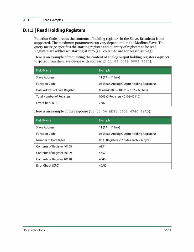
Read ExamplesD - 4
HSQ Technology v6.14
D.1.3 | Read Holding Registers
Function Code 3 reads the contents of holding registers in the Slave. Broadcast is not supported. The maximum parameters can vary dependent on the Modbus Slave. The query message specifies the starting register and quantity of registers to be read. Registers are addressed starting at zero (i.e., coils 1-16 are addressed as 0-15).
Here is an example of requesting the content of analog output holding registers #40108 to 40110 from the Slave device with address 17 (11 03 006B 0003 7687):
Here is an example of the response (11 03 06 AE41 5652 4340 49AD):
Field Name Example
Slave Address 11 (17 = 11 hex)
Function Code 03 (Read Analog Output Holding Registers)
Data Address of First Register 006B (40108 − 40001 = 107 = 6B hex)
Total Number of Registers 0003 (3 Registers 40108-40110)
Error Check (CRC) 7687
Field Name Example
Slave Address 11 (17 = 11 hex)
Function Code 03 (Read Analog Output Holding Registers)
Number of Data Bytes 06 (3 Registers × 2 bytes each = 6 bytes)
Contents of Register 40108 AE41
Contents of Register 40109 5652
Contents of Register 40110 4340
Error Check (CRC) 49AD

v6.14 RTU Diagnostics User Manual
Modbus Message Formats D - 5
D.1.4 | Read Input Registers
Function Code 4 reads the contents of analog input registers in the Slave. Broadcast is not supported. The maximum parameters can vary dependent on the Modbus Slave. The query message specifies the starting register and quantity of registers to be read. Registers are addressed starting at zero (i.e., coils 1-16 are addressed as 0-15).
Here is an example of requesting the content of analog input register #30009 from the Slave device with address 17 (11 04 0008 0001 B298):
Here is an example of the response (11 04 02 000A F8F4):
Field Name Example
Slave Address 11 (17 = 11 hex)
Function Code 04 (Read Analog Input Registers)
Data Address of First Register 0008 (30009 − 30001 = 8)
Total Number of Registers 0001 (1 Register)
Error Check (CRC) B298
Field Name Example
Slave Address 11 (17 = 11 hex)
Function Code 04 (Read Analog Input Registers)
Number of Data Bytes 02 (1 Register × 2 bytes each = 2 bytes)
Contents of Register 30009 000A
Error Check (CRC) F8F4

Write ExamplesD - 6
HSQ Technology v6.14
D.2 | Write Examples
D.2.1 | Force Single Coil
Function Code 5 forces a single coil to either ON or OFF. When broadcast, the function forces the same coil references in all attached Slaves. The maximum parameters can vary dependent on the Modbus Slave. The function will override the controller’s memory protect state and the coil’s disable state. The forced state remains in effect until the controller’s logic overrides any manual commands. Registers not involved in the controller logic will keep the manually set values indefinitely. Coils are addressed starting at zero (i.e., coil 1 is addressed as 0).
The normal response is an echo of the query, returned after the coil has been written. Here is an example of writing the contents of discrete coil #173 to ON in the Slave device with address 17 (11 05 00AC FF00 4E8B):
The normal response is an echo of the query, returned after the coil state has been forced. Here is an example of the response (11 05 00AC FF00 4E8B):
Field Name Example
Slave Address 11 (17 = 11 hex)
Function Code 05 (Force Single Coil)
Data Address of the Coil 00AC (Coil #173 − 1 = 172 = AC hex)
Status to Write FF00 (FF00 = ON, 0000 = OFF)
Error Check (CRC) 4E8B
Field Name Example
Slave Address 11 (17 = 11 hex)
Function Code 05 (Force Single Coil)
Data Address of the Coil 00AC (Coil #173 − 1 = 172 = AC hex)
Status Written FF00
Error Check (CRC) 4E8B

v6.14 RTU Diagnostics User Manual
Modbus Message Formats D - 7
D.2.2 | Preset Single Register
Function Code 6 presets a value into a single holding register. When broadcast, the function presets the same register reference in all attached Slaves. The maximum parameters can vary dependent on the Modbus Slave. The function will override the controller’s memory protect state and the coil’s disable state. The forced state remains in effect until the controller’s logic overrides any manual commands. Registers not involved in the controller logic will keep the manually set values indefinitely. The query message specifies the register reference to be preset. Registers are addressed starting at zero (i.e., register 1 is addressed as 0).
Here is an example of writing the contents of analog output holding register #40002 to the Slave device with address 17 (11 06 0001 0003 9A9B):
The normal response is an echo of the query, returned after the register contents have been written. Here is an example of the response (11 06 0001 0003 9A9B):
Field Name Example
Slave Address 11 (17 = 11 hex)
Function Code 06 (Preset Single Register)
Data Address of the Register 0001 (#40002 − 40001 = 1)
Value to Write 0003
Error Check (CRC) 9A9B
Field Name Example
Slave Address 11 (17 = 11 hex)
Function Code 06 (Preset Single Register)
Data Address of the Register 0001 (#40002 − 40001 = 1)
Value Written 0003
Error Check (CRC) 9A9B

Write ExamplesD - 8
HSQ Technology v6.14
D.2.3 | Force Multiple Coils
Function Code 15 forces each coil in a sequence of coils to either ON or OFF. When broadcast, the function forces the same coil reference in all attached Slaves. The maximum parameters can vary dependent on the Modbus Slave. The function will override the controller’s memory protect state and the coil’s disable state. The forced state remains in effect until the controller’s logic overrides any manual commands. Registers not involved in the controller logic will keep the manually set values indefinitely. The query message specifies the coil references to be forced. Coils are addressed starting at zero (i.e., coil 1 is addressed as 0). The requested ON/OFF states are specified by contents of the query data field. A logical 1 in bit position of the field requests the corresponding coils to be ON. A logical 0 requests it to be OFF.
Here is an example of writing the contents of a series of ten discrete coils #20 to 29 to the Slave device with address 17 (11 0F 0013 000A 02 CD01 BF0B):
Here is an example of the response (11 0F 0013 000A 2699):
The more significant bits contain the higher coil variables. This shows that coil 20 is ON (1) and 21 is OFF (0). Due to the number of coils requested, the last data field contains the status of only two coils. The unused bits in the last data byte are filled in with zeroes.
Field Name Example
Slave Address 11 (17 = 11 hex)
Function Code 0F (Force Multiple Coils, 15 = 0F hex)
Data Address of First Coil 0013 (#20 − 1 = 19 =13 hex)
Number of Coils 000A (10 = 0A hex)
Number of Data Bytes 02 (10 Coils ÷ 8 bits = 2 bytes)
Coils 27-20 (1100 1101)
Coils 29-28 (0000 0001)
CD
01 (includes six space holders)
Error Check (CRC) BF0B
Field Name Example
Slave Address 11 (17 = 11 hex)
Function Code 0F (Force Multiple Coils, 15 = 0F hex)
Data Address of First Coil 0013 (#20 − 1 = 19 =13 hex)
Coils Written 000A (10 = 0A hex)
Error Check (CRC) 2699

v6.14 RTU Diagnostics User Manual
Modbus Message Formats D - 9
D.2.4 | Preset Multiple Registers
Function Code 16 presets values into a sequence of holding registers. When broadcast, this function presets the same register reference in all attached Slaves. The maximum parameters can vary dependent on the Modbus Slave. The function will override the controller’s memory protect. The forced state remains in effect until the controller’s logic overrides any manual commands. Registers not involved in the controller logic will keep the manually set values indefinitely. The query message specifies the register references to be preset. Registers are addressed starting at zero (i.e., register 1 is addressed as zero).
Here is an example of writing the contents of two analog output holding registers #40002 and 40003 to Slave device with address 17 (11 10 0001 0002 04 000A 0102 C6F0):
Here is an example of the response (11 10 0001 0002 1298):
Field Name Example
Slave Address 11 (17 = 11 hex)
Function Code 10 (Preset Multiple Registers, 16 = 10 hex)
Data Address of First Register 0001 (#40002 − 40001 = 1)
Number of Registers 0002
Number of Data Bytes to Follow 04 (2 Registers × 2 Bytes each = 4 bytes)
Value to Write to Register 40002 000A
Value to Write to Register 40003 0102
Error Check (CRC) C6F0
Field Name Example
Slave Address 11 (17 = 11 hex)
Function Code 10 (Preset Multiple Registers, 16 = 10 hex)
Data Address of First Register 0001 (#40002 − 40001 = 1)
Number of Registers Written 0002
Error Check (CRC) 1298

Exception Responses (Error Codes)D - 1 0
HSQ Technology v6.14
D.3 | Exception Responses (Error Codes)
Except for broadcast messages, when a Master device sends a query to a Slave device it expects a normal response. One of the four possible events that can occur from a query by the Master:
If the Slave device receives the query without a communication error and can handle the query normally, it returns a normal response.
If the Slave does not receive the query due to a communication error, no response is returned. The Master will eventually process a timeout condition for the query.
If the Slave receives the query, but detects a communication error (parity, LRC, or CRC), no response is returned. The Master will eventually process a timeout condition for the query.
If the Slave receives the query without a communication error but cannot handle it (e.g., if the request is to read a nonexistent coil or register), the Slave will return an exception response informing the Master of the nature of the error. The exception response message has two fields that differentiate it from a normal response:
Function Code Field — the most significant bit (MSB) is set to 1 alerting the Master to examine the data field for the exception code.
Data Field — contains the exception code that defines the condition that caused the error.
In a normal response the Slave echoes the function code. To denote an exception response, the function code is shown in the echo with its MSB set to 1. All normal function codes have 0 for their MSB. Therefore, setting this bit to 1 is the signal that the Slave cannot process the request.
Function Code in Request Function Code in Exception Response
01 (01 hex) 0000 0001 129 (81 hex) 1000 0001
02 (02 hex) 0000 0010 130 (82 hex) 1000 0010
03 (03 hex) 0000 0011 131 (83 hex) 1000 0011
04 (04 hex) 0000 0100 132 (84 hex) 1000 0100
05 (05 hex) 0000 0101 133 (85 hex) 1000 0101
06 (06 hex) 0000 0110 134 (86 hex) 1000 0110
15 (0F hex) 0000 1111 143 (8F hex) 1000 1111
16 (10 hex) 0000 0000 144 (90 hex) 1001 0000
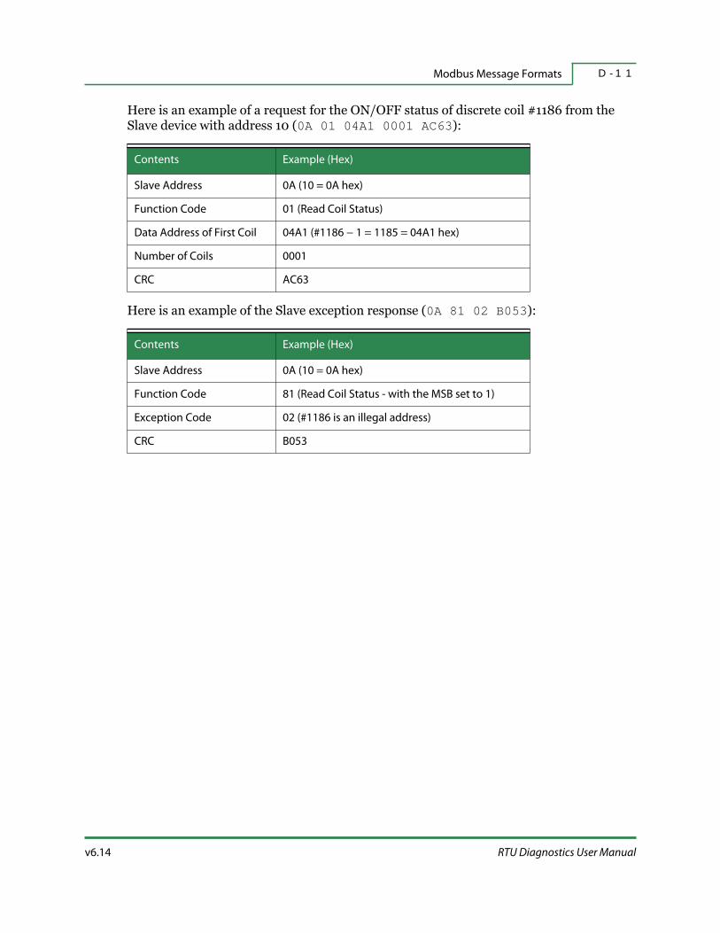
v6.14 RTU Diagnostics User Manual
Modbus Message Formats D - 1 1
Here is an example of a request for the ON/OFF status of discrete coil #1186 from the Slave device with address 10 (0A 01 04A1 0001 AC63):
Here is an example of the Slave exception response (0A 81 02 B053):
Contents Example (Hex)
Slave Address 0A (10 = 0A hex)
Function Code 01 (Read Coil Status)
Data Address of First Coil 04A1 (#1186 − 1 = 1185 = 04A1 hex)
Number of Coils 0001
CRC AC63
Contents Example (Hex)
Slave Address 0A (10 = 0A hex)
Function Code 81 (Read Coil Status - with the MSB set to 1)
Exception Code 02 (#1186 is an illegal address)
CRC B053

Exception Responses (Error Codes)D - 1 2
HSQ Technology v6.14
D.3.1 | Supported Error Codes
Following the Function Code is the Exception Code. The exception code gives an indication of the nature of the problem. The possible codes are shown below:
Error Code Name Meaning
01 Illegal Function
The function code received in the query is not an
allowable action for the slave. This may be because the
function code is only applicable to newer devices, and
was not implemented in the unit selected. It could also
indicate that the slave is in the wrong state to process a
request of this type (e.g., because it is unconfigured and is
being asked to return register values). If a Poll Program
Complete command was issued, this code indicates that
no program function preceded it.
02 Illegal Data Address
The data address received in the query is not an allowable
address for the slave. More specifically, the combination
of reference number and transfer length is invalid. For
example, a controller with 100 registers and a request
with offset 96 and length 4 would succeed, a request with
offset 96 and length 5 will generate error code 02.
03 Illegal Data Value
A value contained in the query data field is not an
allowable value for the slave. This indicates a fault in the
structure of remainder of a complex request, such as the
implied length is incorrect. It specifically does NOT mean
that a data item submitted for storage in a register has a
value outside the expectation of the application program,
since the Modbus protocol is unaware of the significance
of any particular value of any particular register.

E - 1v6.14 RTU Diagnostics User Manual
A P P E N D I X E
86 SERIES TEST SET CABLE
DIAGRAM
This appendix contains a diagram of the pinout for a null-modem cable used to connect an 86 series RTU (2500/86 or 25x86) to a laptop running RTU Diagnostics.
Figure E-1. 86 Series Test Set Cable
1
2
3
4
5
6
7
8
DCD
RXD
TXD
DTR
SGND
DSR
RTS
CTS
DCD
RXD
TXD
DTR
SGND
DSR
RTS
CTS
1
2
3
4
5
6
7
8
DE9 F AT: DE9 F

E - 2
HSQ Technology v6.14

F - 1v6.14 RTU Diagnostics User Manual
A P P E N D I X F
MODULE DRAWINGS
This appendix shows the wiring connections and jumper settings for the HSQ-6017, HSQ-6024, and HSQ-6224 modules.

F - 2
HSQ Technology v6.14
This page left blank intentionally.

v6.14 RTU Diagnostics User Manual
Module Drawings F - 3
Figure F-1. HSQ-6017 Module
/IP:
DO CONNECTIONS
Vin
7-
s a l e s @ h s q . c o m
++24V K
Vin
7+
Vin
6-
Vin
6+
Vin
5-
Vin
5+
Vin
4-
Vin
4+
-
DO COMMON
(B)
GN
D(R
) +
Vs
Iso
GN
DD
O 1
DO
0
COMMON
+24
Vin
0+
w w w . h s q . c o m
AI CONNECTIONS
100MB-RED10MB-OFF
EXCEPTIONS
Active-FLASHRunning Link-GRN
TRANSMITTER
Vin
0-
Vin
1+
Vin
1-
Vin
2+
Vin
2-
Vin
3+
Vin
3-
Iso.
GN
D
-LOOP POWERED
CURRENT
COMMON
+
+24V
31+ TRANMITTER
(4-20mA)8 AI2 DO
NORMAL
(Eth
erne
t)RJ-
45
TRANSMITTERCURRENT
SELF POWERED
VOLTAGE-
+-
2 3
REFER TO FIGURE 1 FOR JUMPER SETTINGS.
MODULE POWER CAN BE 10-30VDC.4.
3
VOLTAGE INPUTS ±150mV, ±500mV, ±1V, ±5V, ±10V.
CURRENT INTPUTS 0-20mA, 4-20mA
NOTES:
1
2
CONNECTION DRAWING
26017-023DESIGNED B.N.
Z:\HSQ\6017\023
DRAWNSCALE
G.B.NONE
DATE 3/31/10
HSQ-6017
JOB NO. DRAWING NO.
BREV.
CH'KA
NO.3/31/10
DATEFOR APPROVAL
REVISIONSG.B.BY ENG.
(Ethernet)
AI3 J9
J5
J4
J3
J2
ANALOG INPUT JUMPER SETTINGS
FIGURE 1
AI7
AI6
AI5
AI4
AI0
AI1
J6
J7
AI2 J8
TYPESETTING
RJ-45
mA
mV, V
JUMPER INPUT
JP1
J2-9
B 8/19/11 REVISED JUMPERS G.B.C.N.

Module DrawingsF - 4
HSQ Technology v6.14
Figure F-2. HSQ-6024 Module
FOR APPROVALDESCRIPTION
A 10/8/09
DATENO.
V
I
J4
VI J5
J6V I V
I
J10
J9
(Eth
erne
t)RJ-
45
J7
VJ1 I J2V I
V
J3I
IJ8 V
SIGNAL, THE SOFTWARE SETTING AND THE JUMPER4-20mA (DEFAULT), 0-20mA OR 0-10V. FOR EACHANALOG OUTPUT HAS A SOFTWARE SETTING FOR4-20mA, 0-20mA (DEFAULT) OR ±10V. EACHEACH ANALOG INPUT HAS A SOFTWARE SETTING FOR
INTERNAL JUMPER POSITIONSHSQ-6024
JOB NO.
G.B.BY CH'K
NONESCALEZ:\HSQ\6024\030ENG
10/8/09
DRAWNDESIGNEDDATE
G.B.C.N.
SETTING MUST MATCH.
3.
A26024-030DRAWING NO. REV.
(#0 PHILLIPS) SCREWS ON THE BACK OF THEOPEN THE CASE BY REMOVING 2 SMALLLOOSENING THE SILVER SCREWS ON THE FRONT.FROM THE REAR MOUNTING BRACKET BYTO ACCESS JUMPERS, REMOVE THE MODULE
POSITION FOR VOLTAGE SIGNAL.FOR CURRENT SIGNAL. MOVE JUMPER TO 'V'EACH JUMPER IS SHOWN IN DEFAULT POSITION 'I'
INPUT OR OUTPUT
AO 1AO 0AI 5AI 4AI 3AI 2AI 1AI 0
J2
MODULE.
2.
J9 & 10
J5
J7 & 8J6
J4J3
NOTES:
1.
JUMPER
J1

v6.14 RTU Diagnostics User Manual
Module Drawings F - 5
Figure F-3. HSQ-6224 Module
NONEG.B.
ENG.CH'KBYDATENO.
SCALEDRAWNDESIGNEDDATE JOB NO. REV.DRAWING NO.
REVISIONSA 9/6/16 FOR APPROVAL G.B.
A
24V COM B1
A
B
A
B2
A
B
A
B3
A
B
A
B4
A
B
A
B1
A
B
A
B2
A
B
A
B3
A
B
A
B4
A
B
A
24V COM
1
NOTES:
24V COM
+24VDC
C.N.
HSQ 6224
9/6/16
Z:\HSQ\6224\02426224-024
SIGNAL. LAST 2 AO's WIRED FOR VOLTAGE (V)FIRST 2 AO's SHOWN WIRED FOR mA CURRENT (I)
TYPICAL CONNECTIONDRY CONTACT
TERMINAL BLOCK WIRING
s a l e s @ h s q . c o m
AO
2.I+
AO
0.V+
Iso.
GN
D
AO
0.I+
AO
1.V+
AO
1.I+
AO
2.V+
Iso.
GN
D
AO
3.V+
Iso.
GN
D
AO
3.I+
NC
w w w . h s q . c o m
HSQ-6224Link 1 Speed 1
Status COM
DI
3
DI
2
DI
1
DI
0
DG
ND
TYPE
(Por
t 1)
Ethe
rnet
+Vs
-Vs
Iso.
GN
D
(Por
t 2)
Ethe
rnet
Link 2 Speed 2
4-ch AO & 4-ch DI
OUTPUT RANGEVoltage ± 5 V
± 10 V0-5 V
0-10 VCurrent 4 - 20 mA
0 - 20 mA
1 10 155
TYPEDI
SIGNALBit 0 - 3
Dry contacts only
IP:
1 SIGNAL. THIS WIRING SHOULD BE CUSTOMIZEDTO MATCH THE CONNECTED DEVICES.
mA CONTROLLEDDEVICE
+
-
VOLTAGE CONTROLLEDDEVICE
+
-

F - 6
HSQ Technology v6.14

G - 1v6.14 RTU Diagnostics User Manual
A P P E N D I X G
GLOSSARY
A
Acronym
A unique string of characters that identifies a specific point throughout the MISER system. An acronym can be any combination of letters from A to Z, numbers 0 - 9, periods (.), dollar signs ($), and hyphens (-). An acronym cannot contain blank spaces and it cannot be made to resemble a numeric value (e.g., -1.5).
B
Baud Rate
The number of symbol changes per second in digital communications. A symbol is either a pulse (in digital baseband transmission) or a tone (in passband transmission using modems) and can be one or several bits of data.
Boolean
A data type that has two values, typically true and false. A Boolean operation describes how to determine a value output based on some logical calculation from Boolean inputs.

COS — Change-Of-StateG - 2
HSQ Technology v6.14
C
COS — Change-Of-State
When inputs or outputs change their state (e.g., OFF to ON or 50% to 75%). In the case of analog points, this happens when the tolerance is exceeded or an alarm status is changed, for digital points it happens when there is any change.
Control Block
An algorithm that receives input, performs a particular calculation, and makes the results available at output. Control Blocks can calculate numeric data and logical data.
D
DIP — Dual Inline Package
DIP switches are manual electric switches designed for use on a Printed Circuit Board (PCB). They provide customization capabilities for electronic devices in specific situations.
E
EEPROM — Electrically Erasable Programmable Read-Only Memory
See “Non-Volatile Memory” on page G-3.
Ethernet Crossover Cable
A type of Ethernet cable used to connect two computers directly together.
F
Frame
A digital data transmission unit or data packet that includes frame synchronization (i.e., a sequence of bits or symbols making it possible to detect the beginning and end of the packet in the stream of symbols or bits).
I
IP Address
Ethernet address of the RTU is expressed in dotted decimal notation consisting of four numbers, ranging from 0 to 255, separated by a period.

v6.14 RTU Diagnostics User Manual
Glossary G - 3
K
Kermit
A computer file transfer/management protocol that provides a universal method for file transfer, terminal emulation, script programming, and character set across different OSs.
M
MISER
A real-time, distributed database software system for use in data acquisition, telemetry, SCADA, process automation, and facility management applications.
MUX — Multiplexer
A device that selects one of several analog or digital input signals and forwards the selected input to a single output line. A multiplexer of 2n inputs has n select lines, which are used to select which input line to send to the output. This allows more data to be sent over a network within a certain amount of time and bandwidth. A MUX is also called a data selector.
Modulus
A term in computer programming that describes the remainder of a number after division or other computational function. For example, to determine the time of day using a 12-hour clock and adding four hours to 9:00, the answer is 1:00 (9 + 4 = 1). Nine plus four equals thirteen, modulus twelve leaves a remainder of one.
N
NCC — Network Communications Controller
A software module that maintains communications using a polled asynchronous method. Communication protocols directed by MISER, to and from RTUs, consist of polled requests and commands.
Non-Volatile Memory
Memory that can retain stored information even when it is not powered on.
Null Modem
A communication method used to connect two devices directly using an RS-232 serial cable.

OctalG - 4
HSQ Technology v6.14
O
Octal
A base-8 number system that uses digits zero to seven.
R
RAM — Random-Access Memory
Volatile memory that stores information for quick access. The information is available until it is overwritten or there is an interruption in power.
RPN — Reverse Polish Notation
A mathematical notation where every number precedes the operation (e.g., 2 2 +). Also known as Postfix Notation.
RTS — Request To Send
A node wishing to send data initiates the process by sending an RTS frame. The destination node replies with a Clear To Send (CTS) frame.
RTU — Remote Terminal Unit
An electronic device that connects objects in the physical world to a distributed control system or SCADA host.
S
SCADA — Supervisory Control and Data Acquisition
A system for remote monitoring and control that operates with coded signals over communication channels.
Subnet Mask
A subdivision of an IP address into the network and host addresses.
1v6.14 RTU Diagnostics User Manual
IndexNumerics
6000 RTU ID, 6-27
A
AICOS tolerance, 6-12force COS, 4-14
B
back porch, 3-10board address, 8-9
C
calculator example, 2-13CB insert command, 5-12CBM
clear, 5-9CI
reset, 4-6scan rate, 6-12
COM port, 3-6comm delay after host reset, 6-12command menu, 2-2, 2-4, 2-6Control Block
scan rate, 6-12season offset, 6-12
control ownership, xxvCOS
by record number, 6-12
discard trigger, 6-11overflow, 6-12time stamp, 6-12
D
decimal, 2-8define
AI point, 7-8AO point, 7-12CI point, 7-9DI point, 7-11DV point, 7-10global AI point, 7-4global AO point, 7-7global CI point, 7-6global DI point, 7-6global DV, 7-5global SP point, 7-7SP point, 7-12
device ownership, 3-8DI
force COS, 4-14scan rate, 6-12
diag ID-COS enable, 3-7DV
disable, 4-11enable, 4-11flash, 4-9lower, 4-6raise, 4-6release, 4-10select, 4-10
HSQ Technology v6.14
IndexI - 2
select for start, 4-11select for stop, 4-11start, 4-6stop, 4-6
DV commandsflash, 8-19raise/lower, 8-19start/stop, 8-18
E
encryption, 6-14
F
first Control Block scan delay, 6-12force stand alone, 6-5front porch, 3-7function keys, 2-7
H
hexadecimal, 2-8hot keys, 2-6
I
initialize RTU, 7-17
L
load from file, 3-14
M
mappingAUX points, 8-12setpoints, 8-13virtual points, 8-12
max frame size, 6-13Modbus slave
analog input register, 9-3analog output holding register, 9-3discrete input contact, 9-3discrete output coil, 9-3
modem, 6-23
modify command, 5-10MUX
DI, 4-15disable, 4-13DO, 4-15enable, 4-13status, 4-15
N
network protocol, 6-21node, xxiii
O
octal, 2-8offline time trigger, 6-11
P
PLC error messages, 8-28PLC Table
1st PT, 9-24BIT CHECK, 9-23FILE NUM, 9-24LAST PT, 9-24PLC ID, 9-24PLC TYPE, 9-23REG NUM, 9-24TYPE and MASK, 9-25
point, xxivcontrol, 7-15involvement command, 5-12
point map, 6-9point table
AI, 8-15DV, 8-18PLC, 8-24SP, 8-21
point types, 8-6poll command, 4-3previous commands, 2-2, 2-4protocol port, 6-13purge command, 5-14

Index
v6.14 RTU Diagnostics User Manual
I - 3
purge definitions, 7-17
R
readconfig, 6-15diagnostics, 6-5directory, 6-5memory, 4-3
read command, 4-2report date stamp, 4-14responses, 2-2responses window, 2-5retries, 3-10RIO ID, 8-10RTU
disable, 4-13, 6-4enable, 4-13, 6-5force COS, 4-14get status, 6-4reboot, 6-4
RTU ID coefficient, 6-20
S
save to file, 3-13select subset, 7-15select/check/operate, 6-13
timeout, 6-13select/check/operate table, 6-25set throttle, 6-5show command, 5-7slide, xxvistandalone time trigger, 6-11start/stop DO command, 8-19string, 5-2
clear, 5-3custom header, 5-4custom packet, 5-4display, 5-3display raw, 5-4load file, 5-6save file, 5-6
send, 5-3supported board types, 8-7
T
target, xxvititle block, 2-2, 2-3
U
unforce stand alone, 6-5unit
address, xxivID, xxiii
userprivileged, xxvstandard, xxv
W
wildcard characters, 2-8write
AI, 4-8AO, 4-8DI, 4-8memory, 4-7SP, 4-8
write commands, 4-5

HSQ Technology v6.14
IndexI - 4


