127
HARDWARE INSTALLATION GUIDE Ruckus ICX 7250 Switch Hardware Installation Guide Part Number: 53-1003898-08 Publication Date: 25 January 2019

HARDWARE INSTALLATION GUIDE
Ruckus ICX 7250 SwitchHardware Installation Guide
Part Number: 53-1003898-08Publication Date: 25 January 2019

Copyright, Trademark and Proprietary RightsInformation© 2019 ARRIS Enterprises LLC. All rights reserved.
No part of this content may be reproduced in any form or by any means or used to make any derivative work (such astranslation, transformation, or adaptation) without written permission from ARRIS International plc and/or its affiliates ("ARRIS").ARRIS reserves the right to revise or change this content from time to time without obligation on the part of ARRIS to providenotification of such revision or change.
Export RestrictionsThese products and associated technical data (in print or electronic form) may be subject to export control laws of the UnitedStates of America. It is your responsibility to determine the applicable regulations and to comply with them. The following noticeis applicable for all products or technology subject to export control:
These items are controlled by the U.S. Government and authorized for export only to the country of ultimate destination for use by theultimate consignee or end-user(s) herein identified. They may not be resold, transferred, or otherwise disposed of, to any other countryor to any person other than the authorized ultimate consignee or end-user(s), either in their original form or after being incorporatedinto other items, without first obtaining approval from the U.S. government or as otherwise authorized by U.S. law and regulations.
DisclaimerTHIS CONTENT AND ASSOCIATED PRODUCTS OR SERVICES ("MATERIALS"), ARE PROVIDED "AS IS" AND WITHOUT WARRANTIES OFANY KIND, WHETHER EXPRESS OR IMPLIED. TO THE FULLEST EXTENT PERMISSIBLE PURSUANT TO APPLICABLE LAW, ARRISDISCLAIMS ALL WARRANTIES, EXPRESS OR IMPLIED, INCLUDING, BUT NOT LIMITED TO, IMPLIED WARRANTIES OFMERCHANTABILITY AND FITNESS FOR A PARTICULAR PURPOSE, TITLE, NON-INFRINGEMENT, FREEDOM FROM COMPUTER VIRUS,AND WARRANTIES ARISING FROM COURSE OF DEALING OR COURSE OF PERFORMANCE. ARRIS does not represent or warrantthat the functions described or contained in the Materials will be uninterrupted or error-free, that defects will be corrected, orare free of viruses or other harmful components. ARRIS does not make any warranties or representations regarding the use ofthe Materials in terms of their completeness, correctness, accuracy, adequacy, usefulness, timeliness, reliability or otherwise. Asa condition of your use of the Materials, you warrant to ARRIS that you will not make use thereof for any purpose that is unlawfulor prohibited by their associated terms of use.
Limitation of LiabilityIN NO EVENT SHALL ARRIS, ARRIS AFFILIATES, OR THEIR OFFICERS, DIRECTORS, EMPLOYEES, AGENTS, SUPPLIERS, LICENSORSAND THIRD PARTY PARTNERS, BE LIABLE FOR ANY DIRECT, INDIRECT, SPECIAL, PUNITIVE, INCIDENTAL, EXEMPLARY ORCONSEQUENTIAL DAMAGES, OR ANY DAMAGES WHATSOEVER, EVEN IF ARRIS HAS BEEN PREVIOUSLY ADVISED OF THEPOSSIBILITY OF SUCH DAMAGES, WHETHER IN AN ACTION UNDER CONTRACT, TORT, OR ANY OTHER THEORY ARISING FROMYOUR ACCESS TO, OR USE OF, THE MATERIALS. Because some jurisdictions do not allow limitations on how long an impliedwarranty lasts, or the exclusion or limitation of liability for consequential or incidental damages, some of the above limitationsmay not apply to you.
TrademarksARRIS, the ARRIS logo, Ruckus, Ruckus Wireless, Ruckus Networks, Ruckus logo, the Big Dog design, BeamFlex, ChannelFly,EdgeIron, FastIron, HyperEdge, ICX, IronPoint, OPENG, SmartCell, Unleashed, Xclaim, ZoneFlex are trademarks of ARRISInternational plc and/or its affiliates. Wi-Fi Alliance, Wi-Fi, the Wi-Fi logo, the Wi-Fi CERTIFIED logo, Wi-Fi Protected Access (WPA),the Wi-Fi Protected Setup logo, and WMM are registered trademarks of Wi-Fi Alliance. Wi-Fi Protected Setup™, Wi-Fi Multimedia™,and WPA2™ are trademarks of Wi-Fi Alliance. All other trademarks are the property of their respective owners.
Ruckus ICX 7250 Switch Hardware Installation Guide2 Part Number: 53-1003898-08

ContentsPreface...................................................................................................................................................................................................7
Document Conventions.............................................................................................................................................................................. 7Notes, Cautions, and Warnings.......................................................................................................................................................... 7
Command Syntax Conventions................................................................................................................................................................. 8Document Feedback................................................................................................................................................................................... 8Ruckus Product Documentation Resources............................................................................................................................................. 8Online Training Resources..........................................................................................................................................................................9Contacting Ruckus Customer Services and Support...............................................................................................................................9
What Support Do I Need?....................................................................................................................................................................9Open a Case..........................................................................................................................................................................................9Self-Service Resources.........................................................................................................................................................................9
About This Document........................................................................................................................................................................ 11What's new in this document...................................................................................................................................................................11Supported Software.................................................................................................................................................................................. 11
Overview............................................................................................................................................................................................. 13Hardware features.....................................................................................................................................................................................13
ICX 7250 models.................................................................................................................................................................................13Network and management interfaces............................................................................................................................................ 14
Installation..........................................................................................................................................................................................23Shipping carton contents......................................................................................................................................................................... 23Configuration requirements.....................................................................................................................................................................23Summary of installation tasks..................................................................................................................................................................24Installation precautions............................................................................................................................................................................ 24
General precautions.......................................................................................................................................................................... 24Lifting precautions............................................................................................................................................................................. 24Power precautions............................................................................................................................................................................. 25
Preparing the installation site.................................................................................................................................................................. 25Cabling infrastructure........................................................................................................................................................................25Installation location........................................................................................................................................................................... 25Rack mount installation considerations..........................................................................................................................................26
Installing the device...................................................................................................................................................................................26Desktop installation...........................................................................................................................................................................26Installing the device into a rack........................................................................................................................................................ 27Wall mount installation..................................................................................................................................................................... 55
Connecting devices in a traditional stack............................................................................................................................................... 57Stacking ports and trunks................................................................................................................................................................. 58Stacking configuration requirements.............................................................................................................................................. 58Traditional stack size..........................................................................................................................................................................58Stacking topologies for a traditional stack......................................................................................................................................58
Powering on the system........................................................................................................................................................................... 60Long-reach multimode adaptor module................................................................................................................................................ 60
LRM module part numbers...............................................................................................................................................................60LRM adaptor module specifications ............................................................................................................................................... 61LEDs..................................................................................................................................................................................................... 61ICX platform support for the LRM adaptor module ..................................................................................................................... 62
Ruckus ICX 7250 Switch Hardware Installation GuidePart Number: 53-1003898-08 3

Unpacking the LRM adaptor module.............................................................................................................................................. 63
Installing the EPS4000 .......................................................................................................................................................................65EPS4000 external power supply.............................................................................................................................................................. 65
EPS4000 features and benefits........................................................................................................................................................ 66EPS4000 front and rear panels.........................................................................................................................................................66LEDs..................................................................................................................................................................................................... 68
Items included with the EPS4000............................................................................................................................................................ 69Configuration requirements.....................................................................................................................................................................69Summary of installation tasks..................................................................................................................................................................69Installation precautions............................................................................................................................................................................ 70
General precautions.......................................................................................................................................................................... 70Lifting precautions............................................................................................................................................................................. 70Power precautions............................................................................................................................................................................. 70
Preparing the installation site.................................................................................................................................................................. 71Rack-mount installation considerations..........................................................................................................................................71
Installing the device...................................................................................................................................................................................71Desktop installation...........................................................................................................................................................................72Mounting an external power supply in a rack (two-post)............................................................................................................. 72
Installing an RPS17 PSU............................................................................................................................................................................ 74Uninstalling an RPS17 PSU....................................................................................................................................................................... 75Connecting the EPS4000 cord..................................................................................................................................................................76Powering on the system........................................................................................................................................................................... 78
Connecting devices to the external power supply.........................................................................................................................79Verifying proper operation....................................................................................................................................................................... 79EPS4000 external power supply technical specifications..................................................................................................................... 79
System specifications........................................................................................................................................................................ 79Management...................................................................................................................................................................................... 80LEDs..................................................................................................................................................................................................... 80Other................................................................................................................................................................................................... 80Weight and physical dimensions......................................................................................................................................................80Environmental requirements........................................................................................................................................................... 80Regulatory compliance (EMC)...........................................................................................................................................................81Regulatory compliance (safety)........................................................................................................................................................ 81Regulatory compliance (environmental)......................................................................................................................................... 81
Configuring the Device...................................................................................................................................................................... 83Configuration tasks................................................................................................................................................................................... 83PC or terminal attachment.......................................................................................................................................................................83Password assignment............................................................................................................................................................................... 84
Assigning passwords......................................................................................................................................................................... 85Recovering from a lost password.....................................................................................................................................................85
IP address configuration...........................................................................................................................................................................86Devices running Layer 2 software....................................................................................................................................................86Devices running Layer 3 software....................................................................................................................................................87
Connecting network devices.................................................................................................................................................................... 89Connectors..........................................................................................................................................................................................89Cable specifications........................................................................................................................................................................... 89Connecting to Ethernet or Fast Ethernet hubs...............................................................................................................................89Connecting to workstations, servers, or routers............................................................................................................................90Connecting a network device to a fiber port.................................................................................................................................. 91
Ruckus ICX 7250 Switch Hardware Installation Guide4 Part Number: 53-1003898-08
Troubleshooting network connections................................................................................................................................................... 91Digital optical monitoring................................................................................................................................................................. 91
Testing connectivity................................................................................................................................................................................... 92Pinging an IP address........................................................................................................................................................................ 92Observing LEDs.................................................................................................................................................................................. 92Tracing a route....................................................................................................................................................................................93
Ruckus ICX 7250 Switch Technical Specifications...........................................................................................................................95System specifications................................................................................................................................................................................95Ethernet...................................................................................................................................................................................................... 95LEDs.............................................................................................................................................................................................................96Other........................................................................................................................................................................................................... 96Weight and physical dimensions............................................................................................................................................................. 96Environmental requirements................................................................................................................................................................... 97Power supply specifications (per PSU)....................................................................................................................................................97Power consumption (idle configuration)................................................................................................................................................ 98Power consumption (typical configuration)........................................................................................................................................... 99Power consumption (maximum configuration)...................................................................................................................................100Data port specifications (Ethernet)....................................................................................................................................................... 100Serial port specifications (pinout mini-USB)........................................................................................................................................ 101Serial port specifications (protocol)...................................................................................................................................................... 101Memory specifications............................................................................................................................................................................101Regulatory compliance (EMC)................................................................................................................................................................ 102Regulatory compliance (safety)............................................................................................................................................................. 102Regulatory compliance (environmental).............................................................................................................................................. 102
Managing an ICX 7250 Device......................................................................................................................................................... 103Device management options................................................................................................................................................................. 103Managing temperature settings............................................................................................................................................................ 104
Temperature threshold levels........................................................................................................................................................ 104Fan detection and error checking policies....................................................................................................................................104Shutdown reset time and syslog message................................................................................................................................... 105Displaying the temperature............................................................................................................................................................105Displaying syslog messages for temperature.............................................................................................................................. 106Changing the temperature warning level .................................................................................................................................... 106Changing the temperature poll time............................................................................................................................................. 107
Displaying CPU usage............................................................................................................................................................................. 107Removing MAC address entries.............................................................................................................................................................107
Hardware Maintenance Schedule.................................................................................................................................................. 109Pre-connection cleaning recommendations........................................................................................................................................ 109Copper or fiber-optic module replacement......................................................................................................................................... 109
Removing a copper or fiber-optic module....................................................................................................................................109Installing a fiber-optic transceiver................................................................................................................................................. 110Cabling a fiber-optic transceiver.................................................................................................................................................... 111Cleaning the fiber-optic connectors.............................................................................................................................................. 112
Cabling a fiber-optic transceiver............................................................................................................................................................112
Troubleshooting ...............................................................................................................................................................................113Diagnosing switch indicators................................................................................................................................................................. 113
Installation........................................................................................................................................................................................ 113Power and cooling problems..........................................................................................................................................................113
Ruckus ICX 7250 Switch Hardware Installation GuidePart Number: 53-1003898-08 5

In-band access..................................................................................................................................................................................114
Regulatory Statements....................................................................................................................................................................115CE statement............................................................................................................................................................................................115China ROHS.............................................................................................................................................................................................. 115BSMI statement (Taiwan)........................................................................................................................................................................115Canadian requirements..........................................................................................................................................................................117China CCC statement.............................................................................................................................................................................. 118Europe and Australia (CISPR 32 Class A Warning)............................................................................................................................... 118FCC warning (US only).............................................................................................................................................................................119Germany statement................................................................................................................................................................................ 119KCC statement (Republic of Korea)....................................................................................................................................................... 119VCCI statement........................................................................................................................................................................................ 119
Cautions and Danger Notices......................................................................................................................................................... 121Cautions....................................................................................................................................................................................................121
General cautions.............................................................................................................................................................................. 121Electrical cautions............................................................................................................................................................................ 122
Danger Notices........................................................................................................................................................................................ 123General dangers...............................................................................................................................................................................124Electrical dangers.............................................................................................................................................................................124Dangers related to equipment weight.......................................................................................................................................... 125Laser dangers...................................................................................................................................................................................126
Ruckus ICX 7250 Switch Hardware Installation Guide6 Part Number: 53-1003898-08
Preface• Document Conventions................................................................................................................................................ 7• Command Syntax Conventions................................................................................................................................... 8• Document Feedback..................................................................................................................................................... 8• Ruckus Product Documentation Resources...............................................................................................................8• Online Training Resources............................................................................................................................................9• Contacting Ruckus Customer Services and Support.................................................................................................9
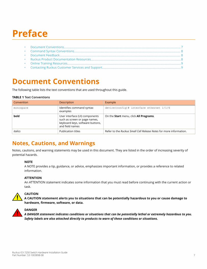
Document ConventionsThe following table lists the text conventions that are used throughout this guide.
TABLE 1 Text ConventionsConvention Description Example
monospace Identifies command syntaxexamples
device(config)# interface ethernet 1/1/6
bold User interface (UI) componentssuch as screen or page names,keyboard keys, software buttons,and field names
On the Start menu, click All Programs.
italics Publication titles Refer to the Ruckus Small Cell Release Notes for more information.
Notes, Cautions, and WarningsNotes, cautions, and warning statements may be used in this document. They are listed in the order of increasing severity ofpotential hazards.
NOTEA NOTE provides a tip, guidance, or advice, emphasizes important information, or provides a reference to relatedinformation.
ATTENTIONAn ATTENTION statement indicates some information that you must read before continuing with the current action ortask.
CAUTIONA CAUTION statement alerts you to situations that can be potentially hazardous to you or cause damage tohardware, firmware, software, or data.
DANGERA DANGER statement indicates conditions or situations that can be potentially lethal or extremely hazardous to you.Safety labels are also attached directly to products to warn of these conditions or situations.
Ruckus ICX 7250 Switch Hardware Installation GuidePart Number: 53-1003898-08 7
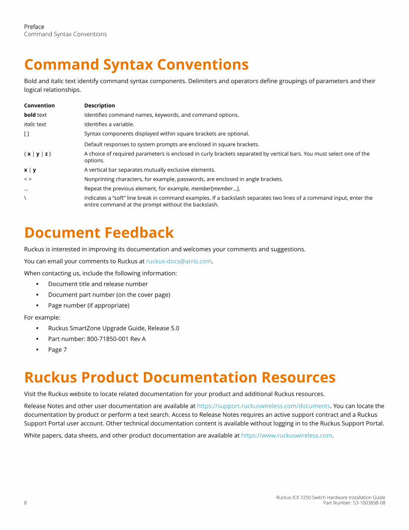
Command Syntax ConventionsBold and italic text identify command syntax components. Delimiters and operators define groupings of parameters and theirlogical relationships.
Convention Description
bold text Identifies command names, keywords, and command options.
italic text Identifies a variable.
[ ] Syntax components displayed within square brackets are optional.
Default responses to system prompts are enclosed in square brackets.
{ x | y | z } A choice of required parameters is enclosed in curly brackets separated by vertical bars. You must select one of theoptions.
x | y A vertical bar separates mutually exclusive elements.
< > Nonprinting characters, for example, passwords, are enclosed in angle brackets.
... Repeat the previous element, for example, member[member...].
\ Indicates a “soft” line break in command examples. If a backslash separates two lines of a command input, enter theentire command at the prompt without the backslash.
Document FeedbackRuckus is interested in improving its documentation and welcomes your comments and suggestions.
You can email your comments to Ruckus at [email protected].
When contacting us, include the following information:
• Document title and release number
• Document part number (on the cover page)
• Page number (if appropriate)
For example:
• Ruckus SmartZone Upgrade Guide, Release 5.0
• Part number: 800-71850-001 Rev A
• Page 7
Ruckus Product Documentation ResourcesVisit the Ruckus website to locate related documentation for your product and additional Ruckus resources.
Release Notes and other user documentation are available at https://support.ruckuswireless.com/documents. You can locate thedocumentation by product or perform a text search. Access to Release Notes requires an active support contract and a RuckusSupport Portal user account. Other technical documentation content is available without logging in to the Ruckus Support Portal.
White papers, data sheets, and other product documentation are available at https://www.ruckuswireless.com.
PrefaceCommand Syntax Conventions
Ruckus ICX 7250 Switch Hardware Installation Guide8 Part Number: 53-1003898-08

Online Training ResourcesTo access a variety of online Ruckus training modules, including free introductory courses to wireless networking essentials, sitesurveys, and Ruckus products, visit the Ruckus Training Portal at https://training.ruckuswireless.com.
Contacting Ruckus Customer Services andSupportThe Customer Services and Support (CSS) organization is available to provide assistance to customers with active warranties ontheir Ruckus products, and customers and partners with active support contracts.
For product support information and details on contacting the Support Team, go directly to the Ruckus Support Portal using https://support.ruckuswireless.com, or go to https://www.ruckuswireless.com and select Support.
What Support Do I Need?Technical issues are usually described in terms of priority (or severity). To determine if you need to call and open a case or accessthe self-service resources, use the following criteria:
• Priority 1 (P1)—Critical. Network or service is down and business is impacted. No known workaround. Go to the Open aCase section.
• Priority 2 (P2)—High. Network or service is impacted, but not down. Business impact may be high. Workaround may beavailable. Go to the Open a Case section.
• Priority 3 (P3)—Medium. Network or service is moderately impacted, but most business remains functional. Go to theSelf-Service Resources section.
• Priority 4 (P4)—Low. Requests for information, product documentation, or product enhancements. Go to the Self-Service Resources section.
Open a CaseWhen your entire network is down (P1), or severely impacted (P2), call the appropriate telephone number listed below to gethelp:
• Continental United States: 1-855-782-5871
• Canada: 1-855-782-5871
• Europe, Middle East, Africa, Central and South America, and Asia Pacific, toll-free numbers are available at https://support.ruckuswireless.com/contact-us and Live Chat is also available.
• Worldwide toll number for our support organization. Phone charges will apply: +1-650-265-0903
We suggest that you keep a physical note of the appropriate support number in case you have an entire network outage.
Self-Service ResourcesThe Ruckus Support Portal at https://support.ruckuswireless.com offers a number of tools to help you to research and resolveproblems with your Ruckus products, including:
• Technical Documentation—https://support.ruckuswireless.com/documents
PrefaceContacting Ruckus Customer Services and Support
Ruckus ICX 7250 Switch Hardware Installation GuidePart Number: 53-1003898-08 9

• Community Forums—https://forums.ruckuswireless.com/ruckuswireless/categories
• Knowledge Base Articles—https://support.ruckuswireless.com/answers
• Software Downloads and Release Notes—https://support.ruckuswireless.com/#products_grid
• Security Bulletins—https://support.ruckuswireless.com/security
Using these resources will help you to resolve some issues, and will provide TAC with additional data from your troubleshootinganalysis if you still require assistance through a support case or RMA. If you still require help, open and manage your case at https://support.ruckuswireless.com/case_management.
PrefaceContacting Ruckus Customer Services and Support
Ruckus ICX 7250 Switch Hardware Installation Guide10 Part Number: 53-1003898-08

About This Document• What's new in this document.....................................................................................................................................11• Supported Software.................................................................................................................................................... 11
What's new in this documentThere are no enhancements in this edition.
Supported SoftwareFor information about the features supported on a hardware platform, refer to the appropriate Features and Standards SupportMatrix document.
Ruckus ICX 7250 Switch Hardware Installation GuidePart Number: 53-1003898-08 11

Ruckus ICX 7250 Switch Hardware Installation Guide12 Part Number: 53-1003898-08
Overview• Hardware features...................................................................................................................................................... 13
Hardware featuresThe following sections describe the physical characteristics of the devices.
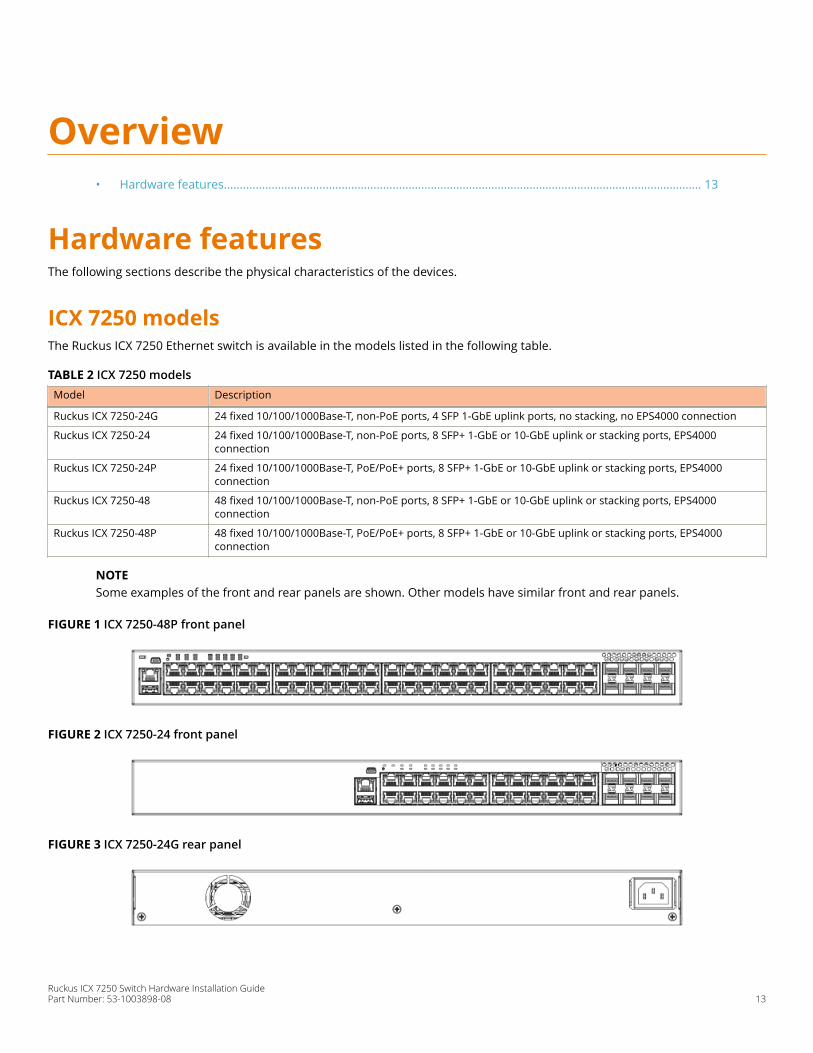
ICX 7250 modelsThe Ruckus ICX 7250 Ethernet switch is available in the models listed in the following table.
TABLE 2 ICX 7250 modelsModel Description
Ruckus ICX 7250-24G 24 fixed 10/100/1000Base-T, non-PoE ports, 4 SFP 1-GbE uplink ports, no stacking, no EPS4000 connection
Ruckus ICX 7250-24 24 fixed 10/100/1000Base-T, non-PoE ports, 8 SFP+ 1-GbE or 10-GbE uplink or stacking ports, EPS4000connection
Ruckus ICX 7250-24P 24 fixed 10/100/1000Base-T, PoE/PoE+ ports, 8 SFP+ 1-GbE or 10-GbE uplink or stacking ports, EPS4000connection
Ruckus ICX 7250-48 48 fixed 10/100/1000Base-T, non-PoE ports, 8 SFP+ 1-GbE or 10-GbE uplink or stacking ports, EPS4000connection
Ruckus ICX 7250-48P 48 fixed 10/100/1000Base-T, PoE/PoE+ ports, 8 SFP+ 1-GbE or 10-GbE uplink or stacking ports, EPS4000connection
NOTESome examples of the front and rear panels are shown. Other models have similar front and rear panels.
FIGURE 1 ICX 7250-48P front panel
FIGURE 2 ICX 7250-24 front panel
FIGURE 3 ICX 7250-24G rear panel
Ruckus ICX 7250 Switch Hardware Installation GuidePart Number: 53-1003898-08 13
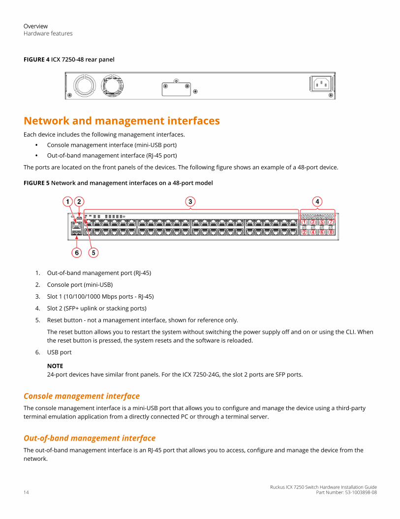
FIGURE 4 ICX 7250-48 rear panel
Network and management interfacesEach device includes the following management interfaces.
• Console management interface (mini-USB port)
• Out-of-band management interface (RJ-45 port)
The ports are located on the front panels of the devices. The following figure shows an example of a 48-port device.
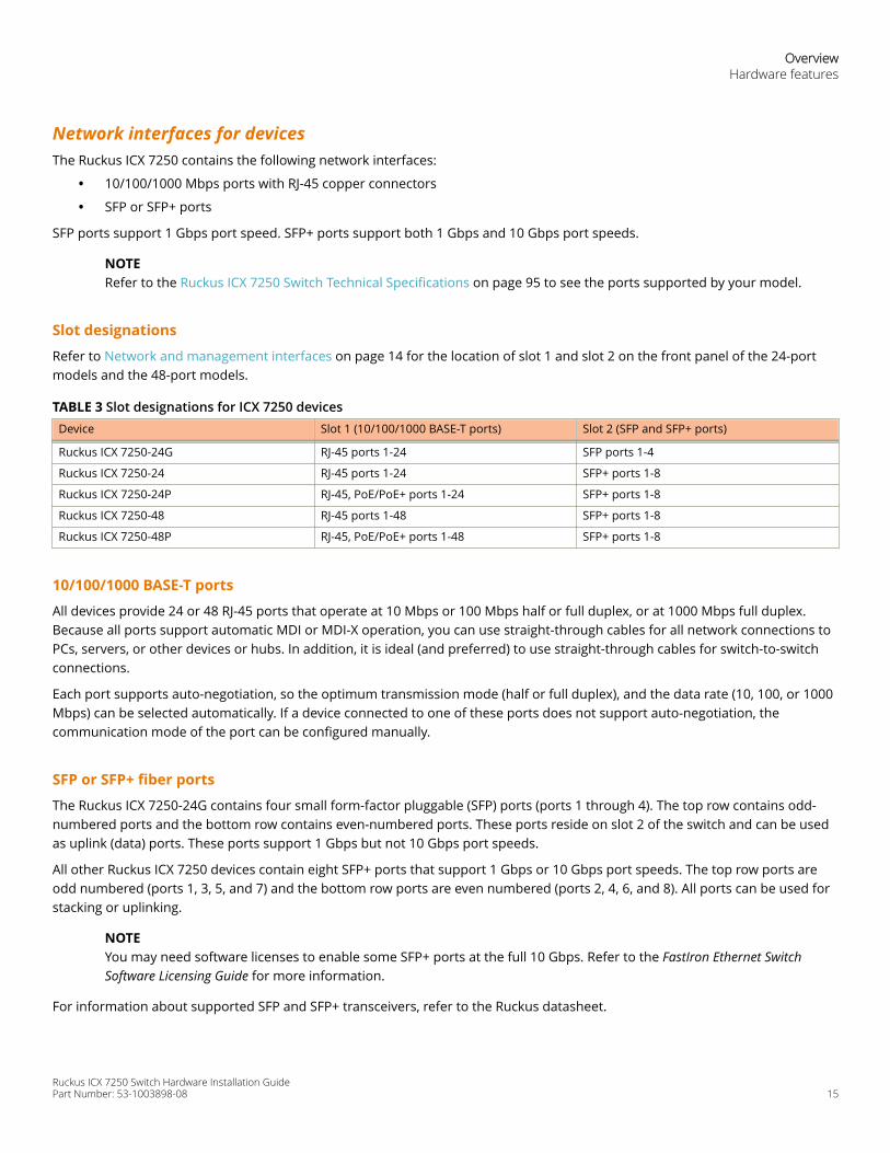
FIGURE 5 Network and management interfaces on a 48-port model
1. Out-of-band management port (RJ-45)
2. Console port (mini-USB)
3. Slot 1 (10/100/1000 Mbps ports - RJ-45)
4. Slot 2 (SFP+ uplink or stacking ports)
5. Reset button - not a management interface, shown for reference only.
The reset button allows you to restart the system without switching the power supply off and on or using the CLI. Whenthe reset button is pressed, the system resets and the software is reloaded.
6. USB port
NOTE24-port devices have similar front panels. For the ICX 7250-24G, the slot 2 ports are SFP ports.
Console management interfaceThe console management interface is a mini-USB port that allows you to configure and manage the device using a third-partyterminal emulation application from a directly connected PC or through a terminal server.
Out-of-band management interfaceThe out-of-band management interface is an RJ-45 port that allows you to access, configure and manage the device from thenetwork.
OverviewHardware features
Ruckus ICX 7250 Switch Hardware Installation Guide14 Part Number: 53-1003898-08
Network interfaces for devicesThe Ruckus ICX 7250 contains the following network interfaces:
• 10/100/1000 Mbps ports with RJ-45 copper connectors
• SFP or SFP+ ports
SFP ports support 1 Gbps port speed. SFP+ ports support both 1 Gbps and 10 Gbps port speeds.
NOTERefer to the Ruckus ICX 7250 Switch Technical Specifications on page 95 to see the ports supported by your model.
Slot designations
Refer to Network and management interfaces on page 14 for the location of slot 1 and slot 2 on the front panel of the 24-portmodels and the 48-port models.
TABLE 3 Slot designations for ICX 7250 devices Device Slot 1 (10/100/1000 BASE-T ports) Slot 2 (SFP and SFP+ ports)
Ruckus ICX 7250-24G RJ-45 ports 1-24 SFP ports 1-4
Ruckus ICX 7250-24 RJ-45 ports 1-24 SFP+ ports 1-8
Ruckus ICX 7250-24P RJ-45, PoE/PoE+ ports 1-24 SFP+ ports 1-8
Ruckus ICX 7250-48 RJ-45 ports 1-48 SFP+ ports 1-8
Ruckus ICX 7250-48P RJ-45, PoE/PoE+ ports 1-48 SFP+ ports 1-8
10/100/1000 BASE-T ports
All devices provide 24 or 48 RJ-45 ports that operate at 10 Mbps or 100 Mbps half or full duplex, or at 1000 Mbps full duplex.Because all ports support automatic MDI or MDI-X operation, you can use straight-through cables for all network connections toPCs, servers, or other devices or hubs. In addition, it is ideal (and preferred) to use straight-through cables for switch-to-switchconnections.
Each port supports auto-negotiation, so the optimum transmission mode (half or full duplex), and the data rate (10, 100, or 1000Mbps) can be selected automatically. If a device connected to one of these ports does not support auto-negotiation, thecommunication mode of the port can be configured manually.
SFP or SFP+ fiber ports
The Ruckus ICX 7250-24G contains four small form-factor pluggable (SFP) ports (ports 1 through 4). The top row contains odd-numbered ports and the bottom row contains even-numbered ports. These ports reside on slot 2 of the switch and can be usedas uplink (data) ports. These ports support 1 Gbps but not 10 Gbps port speeds.
All other Ruckus ICX 7250 devices contain eight SFP+ ports that support 1 Gbps or 10 Gbps port speeds. The top row ports areodd numbered (ports 1, 3, 5, and 7) and the bottom row ports are even numbered (ports 2, 4, 6, and 8). All ports can be used forstacking or uplinking.
NOTEYou may need software licenses to enable some SFP+ ports at the full 10 Gbps. Refer to the FastIron Ethernet SwitchSoftware Licensing Guide for more information.
For information about supported SFP and SFP+ transceivers, refer to the Ruckus datasheet.
OverviewHardware features
Ruckus ICX 7250 Switch Hardware Installation GuidePart Number: 53-1003898-08 15
Specifying a port addressYou can specify a port address for an uplink (data) port, a stacking port, or a management port.
Specifying a data port
The port address format is stack-unit/slot/port:
• stack-unit: Specifies the stack unit ID. The range is from 1 through the maximum number of devices supported in a stack.Refer to the technical specifications for your device for the actual value. If the device is not part of a stack, the stack unitID is 1.
• slot: Specifies the slot number; either 1 or 2.
• port: Specifies the port number in the slot. The range is from 1 through 24 (24-port models) or 1 through 48 (48-portmodels) for the RJ-45 ports. For the SFP ports, the range is from 1 through 4, and for the SFP+ ports, the range is from 1through 8.
The following example shows how to specify port 2 in slot 1 of a device that is not part of a stack:
device (config)# interface ethernet 1/1/2
Specifying a stacking port
The port address format is stack-unit/slot/port:
• stack-unit: Specifies the stack unit ID. For models that support stacking, the range is from 1 through the maximumnumber of devices (units) that can be supported in the stack.
• slot: Specifies the slot number. Stacking ports are in slot 2.
• port: Specifies the port number in the slot.
The following example shows how to specify stacking port 3 in slot 2 of unit 3 in a stack:
device (config)# interface ethernet 3/2/3
Specifying a management port
The management port number is always 1. This example shows how to specify the management port:
device (config)# interface management 1
Port, system, and power status LEDsThe devices include LEDs that indicate the status of device components.
NOTEThe following figures show examples of the port status LEDs for similar ports are present for models with a highernumber of ports.
OverviewHardware features
Ruckus ICX 7250 Switch Hardware Installation Guide16 Part Number: 53-1003898-08
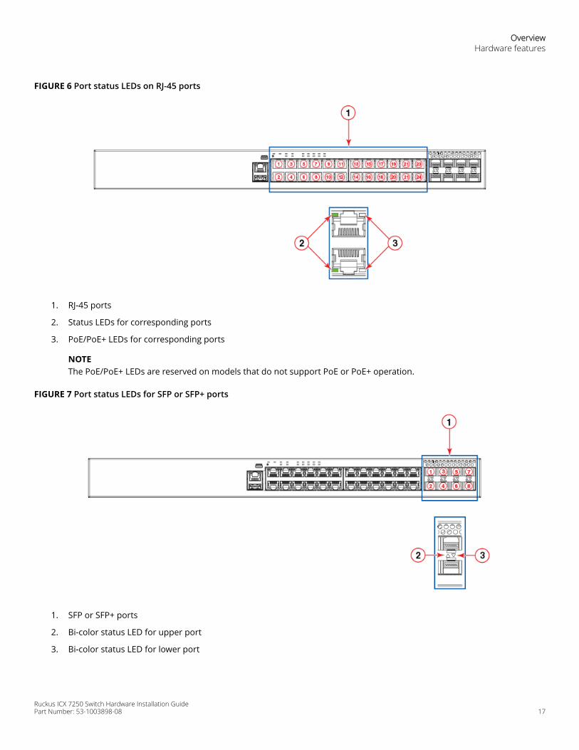
FIGURE 6 Port status LEDs on RJ-45 ports
1. RJ-45 ports
2. Status LEDs for corresponding ports
3. PoE/PoE+ LEDs for corresponding ports
NOTEThe PoE/PoE+ LEDs are reserved on models that do not support PoE or PoE+ operation.
FIGURE 7 Port status LEDs for SFP or SFP+ ports
1. SFP or SFP+ ports
2. Bi-color status LED for upper port
3. Bi-color status LED for lower port
OverviewHardware features
Ruckus ICX 7250 Switch Hardware Installation GuidePart Number: 53-1003898-08 17
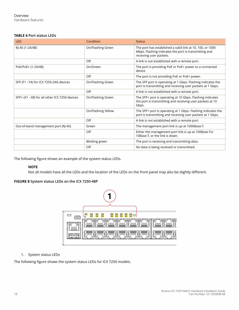
TABLE 4 Port status LEDsLED Condition Status
RJ-45 (1-24/48) On/Flashing Green The port has established a valid link at 10, 100, or 1000Mbps. Flashing indicates the port is transmitting andreceiving user packets.
Off A link is not established with a remote port.
PoE/PoE+ (1-24/48) On/Green The port is providing PoE or PoE+ power to a connecteddevice.
Off The port is not providing PoE or PoE+ power.
SFP (F1 - F4) for ICX 7250-24G devices On/Flashing Green The SFP port is operating at 1 Gbps. Flashing indicates theport is transmitting and receiving user packets at 1 Gbps.
Off A link is not established with a remote port.
SFP+ (X1 - X8) for all other ICX 7250 devices On/Flashing Green The SFP+ port is operating at 10 Gbps. Flashing indicatesthe port is transmitting and receiving user packets at 10Gbps.
On/Flashing Yellow The SFP+ port is operating at 1 Gbps. Flashing indicates theport is transmitting and receiving user packets at 1 Gbps.
Off A link is not established with a remote port.
Out-of-band management port (RJ-45) Green The management port link is up at 1000Base-T.
Off Either the management port link is up at 100Base-Tx/10Base-T, or the link is down.
Blinking green The port is receiving and transmitting data.
Off No data is being received or transmitted.
The following figure shows an example of the system status LEDs.
NOTENot all models have all the LEDs and the location of the LEDs on the front panel may also be slightly different.
FIGURE 8 System status LEDs on the ICX 7250-48P
1. System status LEDs
The following figure shows the system status LEDs for ICX 7250 models.
OverviewHardware features
Ruckus ICX 7250 Switch Hardware Installation Guide18 Part Number: 53-1003898-08
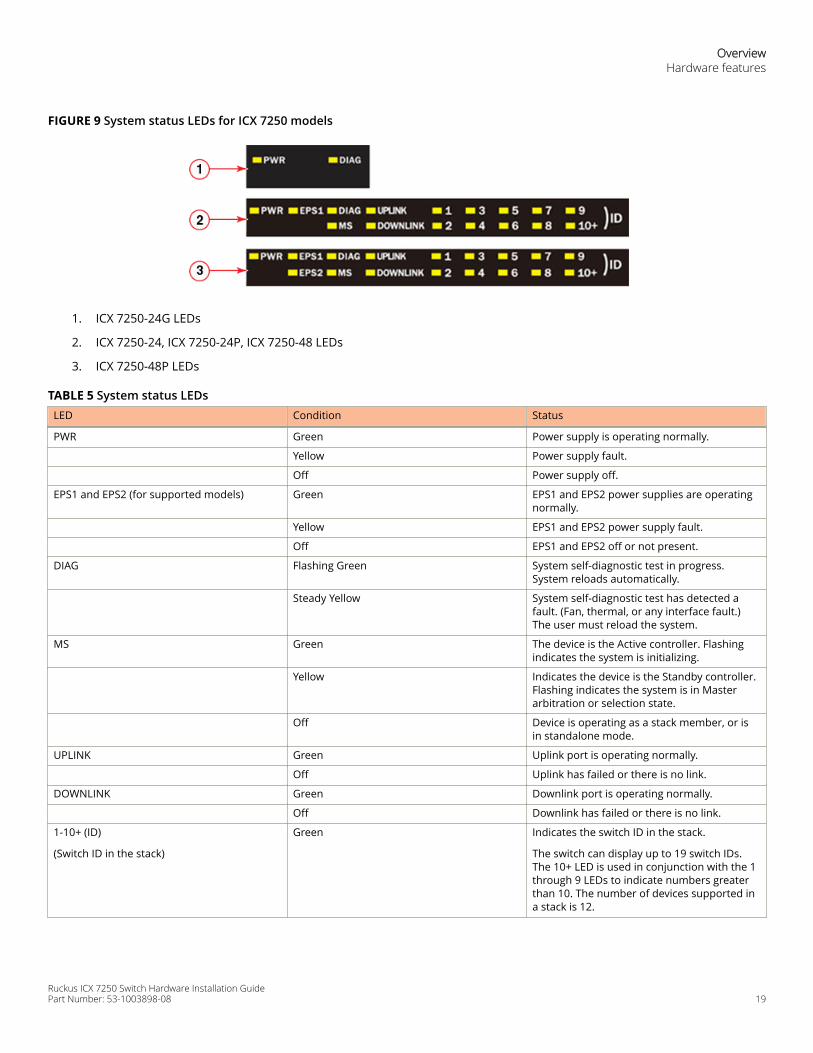
FIGURE 9 System status LEDs for ICX 7250 models
1. ICX 7250-24G LEDs
2. ICX 7250-24, ICX 7250-24P, ICX 7250-48 LEDs
3. ICX 7250-48P LEDs
TABLE 5 System status LEDsLED Condition Status
PWR Green Power supply is operating normally.
Yellow Power supply fault.
Off Power supply off.
EPS1 and EPS2 (for supported models) Green EPS1 and EPS2 power supplies are operatingnormally.
Yellow EPS1 and EPS2 power supply fault.
Off EPS1 and EPS2 off or not present.
DIAG Flashing Green System self-diagnostic test in progress.System reloads automatically.
Steady Yellow System self-diagnostic test has detected afault. (Fan, thermal, or any interface fault.)The user must reload the system.
MS Green The device is the Active controller. Flashingindicates the system is initializing.
Yellow Indicates the device is the Standby controller.Flashing indicates the system is in Masterarbitration or selection state.
Off Device is operating as a stack member, or isin standalone mode.
UPLINK Green Uplink port is operating normally.
Off Uplink has failed or there is no link.
DOWNLINK Green Downlink port is operating normally.
Off Downlink has failed or there is no link.
1-10+ (ID)
(Switch ID in the stack)
Green Indicates the switch ID in the stack.
The switch can display up to 19 switch IDs.The 10+ LED is used in conjunction with the 1through 9 LEDs to indicate numbers greaterthan 10. The number of devices supported ina stack is 12.
OverviewHardware features
Ruckus ICX 7250 Switch Hardware Installation GuidePart Number: 53-1003898-08 19
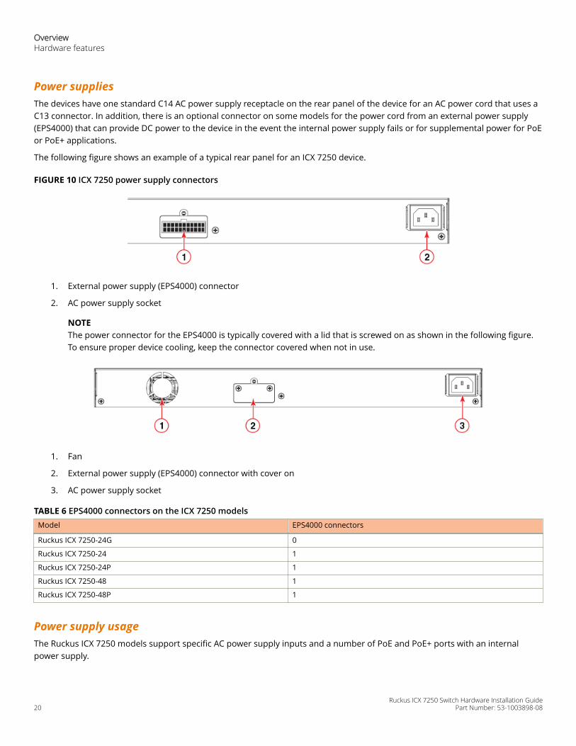
Power suppliesThe devices have one standard C14 AC power supply receptacle on the rear panel of the device for an AC power cord that uses aC13 connector. In addition, there is an optional connector on some models for the power cord from an external power supply(EPS4000) that can provide DC power to the device in the event the internal power supply fails or for supplemental power for PoEor PoE+ applications.
The following figure shows an example of a typical rear panel for an ICX 7250 device.
FIGURE 10 ICX 7250 power supply connectors
1. External power supply (EPS4000) connector
2. AC power supply socket
NOTEThe power connector for the EPS4000 is typically covered with a lid that is screwed on as shown in the following figure.To ensure proper device cooling, keep the connector covered when not in use.
1. Fan
2. External power supply (EPS4000) connector with cover on
3. AC power supply socket
TABLE 6 EPS4000 connectors on the ICX 7250 modelsModel EPS4000 connectors
Ruckus ICX 7250-24G 0
Ruckus ICX 7250-24 1
Ruckus ICX 7250-24P 1
Ruckus ICX 7250-48 1
Ruckus ICX 7250-48P 1
Power supply usageThe Ruckus ICX 7250 models support specific AC power supply inputs and a number of PoE and PoE+ ports with an internalpower supply.
OverviewHardware features
Ruckus ICX 7250 Switch Hardware Installation Guide20 Part Number: 53-1003898-08
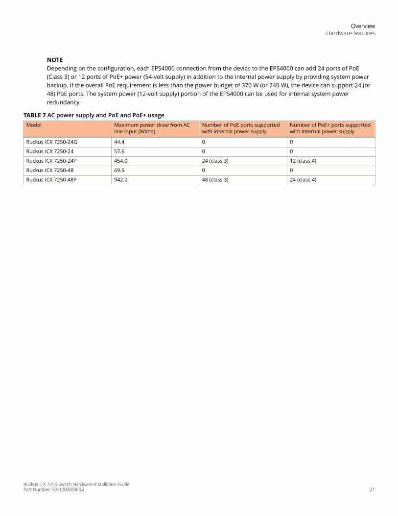
NOTEDepending on the configuration, each EPS4000 connection from the device to the EPS4000 can add 24 ports of PoE(Class 3) or 12 ports of PoE+ power (54-volt supply) in addition to the internal power supply by providing system powerbackup. If the overall PoE requirement is less than the power budget of 370 W (or 740 W), the device can support 24 (or48) PoE ports. The system power (12-volt supply) portion of the EPS4000 can be used for internal system powerredundancy.
TABLE 7 AC power supply and PoE and PoE+ usageModel Maximum power draw from AC
line input (Watts)Number of PoE ports supportedwith internal power supply
Number of PoE+ ports supportedwith internal power supply
Ruckus ICX 7250-24G 44.4 0 0
Ruckus ICX 7250-24 57.6 0 0
Ruckus ICX 7250-24P 454.0 24 (class 3) 12 (class 4)
Ruckus ICX 7250-48 69.5 0 0
Ruckus ICX 7250-48P 942.0 48 (class 3) 24 (class 4)
OverviewHardware features
Ruckus ICX 7250 Switch Hardware Installation GuidePart Number: 53-1003898-08 21

Ruckus ICX 7250 Switch Hardware Installation Guide22 Part Number: 53-1003898-08
Installation• Shipping carton contents........................................................................................................................................... 23• Configuration requirements...................................................................................................................................... 23• Summary of installation tasks................................................................................................................................... 24• Installation precautions.............................................................................................................................................. 24• Preparing the installation site....................................................................................................................................25• Installing the device.....................................................................................................................................................26• Connecting devices in a traditional stack................................................................................................................. 57• Powering on the system............................................................................................................................................. 60• Long-reach multimode adaptor module.................................................................................................................. 60
DANGERThe procedures in this manual are for qualified service personnel.
DANGERBefore beginning the installation, see the precautions in “Power precautions.”
CAUTIONDisassembling any part of the power supply and fan assembly voids the warranty and regulatory certifications.There are no user-serviceable parts inside the power supply and fan assembly.
Shipping carton contentsRuckus ICX 7250 devices ship with all of the following items included in the shipping carton. When unpacking the device, verifythat the contents of the shipping carton is complete, if any items are missing, contact the place of purchase.
• The Ruckus ICX 7250 device
• An accessory kit containing the following items:
– Rack mounting kit containing two L-shaped mounting brackets and two sets of eight sink-head screws– Two-post rack kit containing four rack-mounting screws and four cage nuts– Four rubber feet– One US AC power cord, shielded– Power cord retaining clip– One console cable (Mini-USB to RJ45)– One RJ45-to-DB9 adapter– China ROHS sheet– Read Me First document
Configuration requirementsTo manage the ICX 7250, you need a management station, such as a PC running a terminal emulation application, for serialconnection to the device.
Use the serial connection to perform basic configuration tasks, including assigning an IP address and network mask to thesystem. This information is required to manage the system using the CLI through Telnet or Brocade Network Advisor.
Ruckus ICX 7250 Switch Hardware Installation GuidePart Number: 53-1003898-08 23
Summary of installation tasksFollow the steps in the following table to install your device. Details for each of these steps are provided on the pages indicated.
TABLE 8 Installation tasks Task number Task Where to find more information
1 Ensure that the physical environment that willhost the device has the proper cabling andventilation.
Preparing the installation site on page 25
2 Unpack the device and all includedaccessories.
Shipping carton contents on page 23
3 Install the device on a desktop, or in anequipment rack.
Installing the device on page 26
4 Once the device is installed, plug the deviceinto a nearby power source that adheres tothe regulatory requirements outlined in thismanual.
Powering on the system on page 60
Installation precautionsFollow all precautions when installing a device.
General precautionsDANGERAll fiber-optic interfaces use Class 1 lasers.
CAUTIONDo not install the device in an environment where the operating ambient temperature might exceed 50°C(122°F).
CAUTIONMake sure the airflow around the front, and back of the device is not restricted.
Lifting precautionsDANGERMake sure the rack housing the device is adequately secured to prevent it from becoming unstable or falling over.
DANGERMount the devices you install in a rack as low as possible. Place the heaviest device at the bottom and progressivelyplace lighter devices above.
InstallationSummary of installation tasks
Ruckus ICX 7250 Switch Hardware Installation Guide24 Part Number: 53-1003898-08
Power precautionsCAUTIONUse a separate branch circuit for each power cord, which provides redundancy in case one of the circuits fails.
CAUTIONEnsure that the device does not overload the power circuits, wiring, and over-current protection. To determinethe possibility of overloading the supply circuits, add the ampere (amp) ratings of all devices installed on thesame circuit as the device. Compare this total with the rating limit for the circuit. The maximum ampere ratingsare usually printed on the devices near the input power connectors.
DANGERDisconnect the power cord from all power sources to completely remove power from the device.
DANGERIf the installation requires a different power cord than the one supplied with the device, make sure you use a powercord displaying the mark of the safety agency that defines the regulations for power cords in your country. The markis your assurance that the power cord can be used safely with the device.
Preparing the installation siteBefore installing the device, plan its location and orientation relative to other devices and equipment.
Cabling infrastructureEnsure that the proper cabling is installed at the site. For information about supported SFP and SFP+ transceivers and cablelengths and types, refer to the Ruckus optics family datasheet.
Installation locationDevices can be mounted in a standard 19-inch equipment rack, on the wall, or on a flat surface.
The site should meet the following requirements:
• Maintain the operating environment as specified in the Technical Specifications.
• Allow a minimum of 7.62 cm (3 in.) of space between the front and the back of the device and walls or otherobstructions for proper airflow.
• Allow at least 7.62 cm (3 in.) of space at the front and back of the device for the twisted-pair, fiber-optic, and powercabling.
• The site should be accessible for installing, cabling, and maintaining the devices.
• Allow the status LEDs to be clearly visible.
• Allow for twisted-pair cables to be routed away from power lines, fluorescent lighting fixtures, and other sources ofelectrical interference, such as radios and transmitters.
• Allow for the unit to be connected to a separate grounded power outlet that provides 100 to 240 VAC, 50 to 60 Hz, within2 m (6.6 ft) of each device, and is powered from an independent circuit breaker. As with any equipment, a filter or surgesuppressor is recommended.
• Some combinations of intake and exhaust airflows may not be compatible with your environment.
InstallationPreparing the installation site
Ruckus ICX 7250 Switch Hardware Installation GuidePart Number: 53-1003898-08 25
Rack mount installation considerationsBefore mounting the device in a rack, ensure that the following rack mount installation requirements are met:
• Temperature: Because the temperature within a rack assembly may be higher than the ambient room temperature,check that the rack-environment temperature is within the specified operating temperature range. Refer to Ruckus ICX7250 Switch Technical Specifications on page 95.
• Airflow: Be sure that the airflow direction for all equipment in a rack is the same or consistent.
• Mechanical loading: Do not place any equipment on top of a rack-mounted unit.
• Circuit overloading: Be sure that the supply circuit to the rack assembly is not overloaded.
• Grounding: Rack-mounted equipment should be properly grounded.
Installing the deviceYou can install the device on a desktop, the wall, or in an equipment rack.
DANGERMount the devices you install in a rack as low as possible. Place the heaviest device at the bottom and progressivelyplace lighter devices above.
Desktop installationComplete the following steps to install the ICX 7250 device on a desktop or other flat surface. The device you are installing mightlook different than the one in the following illustration.
DANGERThis equipment is suitable for mounting on concrete or other noncombustible surfaces only.
InstallationInstalling the device
Ruckus ICX 7250 Switch Hardware Installation Guide26 Part Number: 53-1003898-08
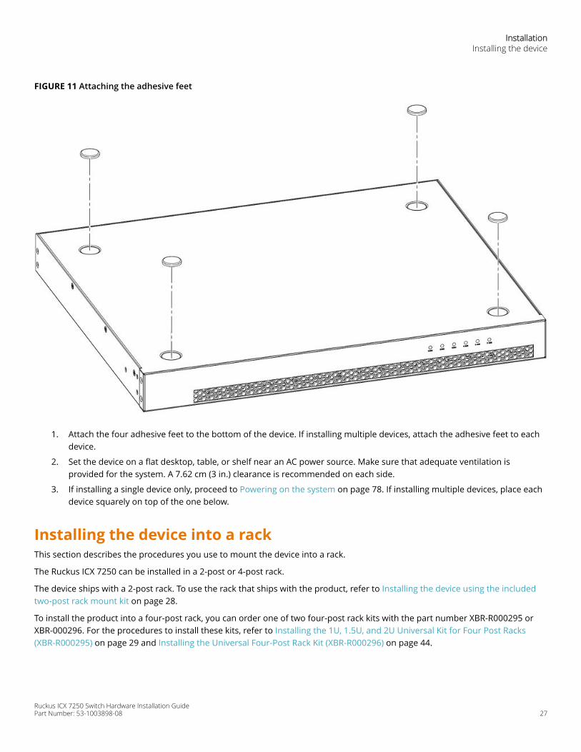
FIGURE 11 Attaching the adhesive feet
1. Attach the four adhesive feet to the bottom of the device. If installing multiple devices, attach the adhesive feet to eachdevice.
2. Set the device on a flat desktop, table, or shelf near an AC power source. Make sure that adequate ventilation isprovided for the system. A 7.62 cm (3 in.) clearance is recommended on each side.
3. If installing a single device only, proceed to Powering on the system on page 78. If installing multiple devices, place eachdevice squarely on top of the one below.
Installing the device into a rackThis section describes the procedures you use to mount the device into a rack.
The Ruckus ICX 7250 can be installed in a 2-post or 4-post rack.
The device ships with a 2-post rack. To use the rack that ships with the product, refer to Installing the device using the includedtwo-post rack mount kit on page 28.
To install the product into a four-post rack, you can order one of two four-post rack kits with the part number XBR-R000295 orXBR-000296. For the procedures to install these kits, refer to Installing the 1U, 1.5U, and 2U Universal Kit for Four Post Racks(XBR-R000295) on page 29 and Installing the Universal Four-Post Rack Kit (XBR-R000296) on page 44.
InstallationInstalling the device
Ruckus ICX 7250 Switch Hardware Installation GuidePart Number: 53-1003898-08 27
Installing the device using the included two-post rack mount kitUse this procedure to install the device to a 2-post rack using the rack-mount ears that are included with the device.
DANGERMake sure the rack housing the device is adequately secured to prevent it from becoming unstable or falling over.
NOTEYou need a #2 Phillips screwdriver for rack mount installation.
Complete the following steps to mount devices in a rack. The example shows a front-mounting.
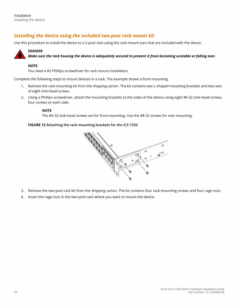
1. Remove the rack mounting kit from the shipping carton. The kit contains two L-shaped mounting brackets and two setsof eight sink-head screws.
2. Using a Phillips screwdriver, attach the mounting brackets to the sides of the device using eight #6-32 sink-head screws,four screws on each side.
NOTEThe #6-32 sink-head screws are for front-mounting. Use the #8-32 screws for rear-mounting.
FIGURE 12 Attaching the rack mounting brackets for the ICX 7250
3. Remove the two-post rack kit from the shipping carton. The kit contains four rack-mounting screws and four cage nuts.
4. Insert the cage nuts in the two-post rack where you want to mount the device.
InstallationInstalling the device
Ruckus ICX 7250 Switch Hardware Installation Guide28 Part Number: 53-1003898-08
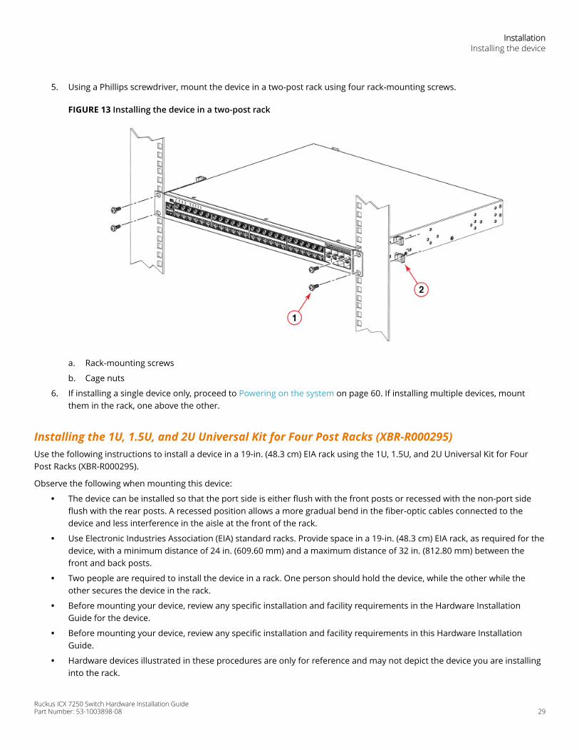
5. Using a Phillips screwdriver, mount the device in a two-post rack using four rack-mounting screws.
FIGURE 13 Installing the device in a two-post rack
a. Rack-mounting screws
b. Cage nuts
6. If installing a single device only, proceed to Powering on the system on page 60. If installing multiple devices, mountthem in the rack, one above the other.
Installing the 1U, 1.5U, and 2U Universal Kit for Four Post Racks (XBR-R000295)Use the following instructions to install a device in a 19-in. (48.3 cm) EIA rack using the 1U, 1.5U, and 2U Universal Kit for FourPost Racks (XBR-R000295).
Observe the following when mounting this device:
• The device can be installed so that the port side is either flush with the front posts or recessed with the non-port sideflush with the rear posts. A recessed position allows a more gradual bend in the fiber-optic cables connected to thedevice and less interference in the aisle at the front of the rack.
• Use Electronic Industries Association (EIA) standard racks. Provide space in a 19-in. (48.3 cm) EIA rack, as required for thedevice, with a minimum distance of 24 in. (609.60 mm) and a maximum distance of 32 in. (812.80 mm) between thefront and back posts.
• Two people are required to install the device in a rack. One person should hold the device, while the other while theother secures the device in the rack.
• Before mounting your device, review any specific installation and facility requirements in the Hardware InstallationGuide for the device.
• Before mounting your device, review any specific installation and facility requirements in this Hardware InstallationGuide.
• Hardware devices illustrated in these procedures are only for reference and may not depict the device you are installinginto the rack.
InstallationInstalling the device
Ruckus ICX 7250 Switch Hardware Installation GuidePart Number: 53-1003898-08 29

Installation requirements
Review the installation and facility requirements for your product before mounting the device. Refer to the hardware installationguide for your product for more information.
Use Electronic Industries Association (EIA) standard racks. Provide space in a 19-in. (48.3 cm) EIA rack, as required for the devicetype, with a minimum distance of 24 in. (609.60 mm) and a maximum distance of 32 in. (812.80 mm) between the front and backposts.
Time and items required
Allow 15 to 30 minutes to complete this procedure. Note the following requirements to ensure correct installation and operation.
The following items are required to install the device using the 1U, 1.5U, and 2U Universal Kit for Four-Post Racks:
• #2 Phillips torque screwdriver
• 1/4-inch slotted-blade torque screwdriver
Parts list
The following parts are provided with the 1U, 1.5U, and 2U Universal Kit for Four Post Racks Installation (XBR-R000295).
InstallationInstalling the device
Ruckus ICX 7250 Switch Hardware Installation Guide30 Part Number: 53-1003898-08
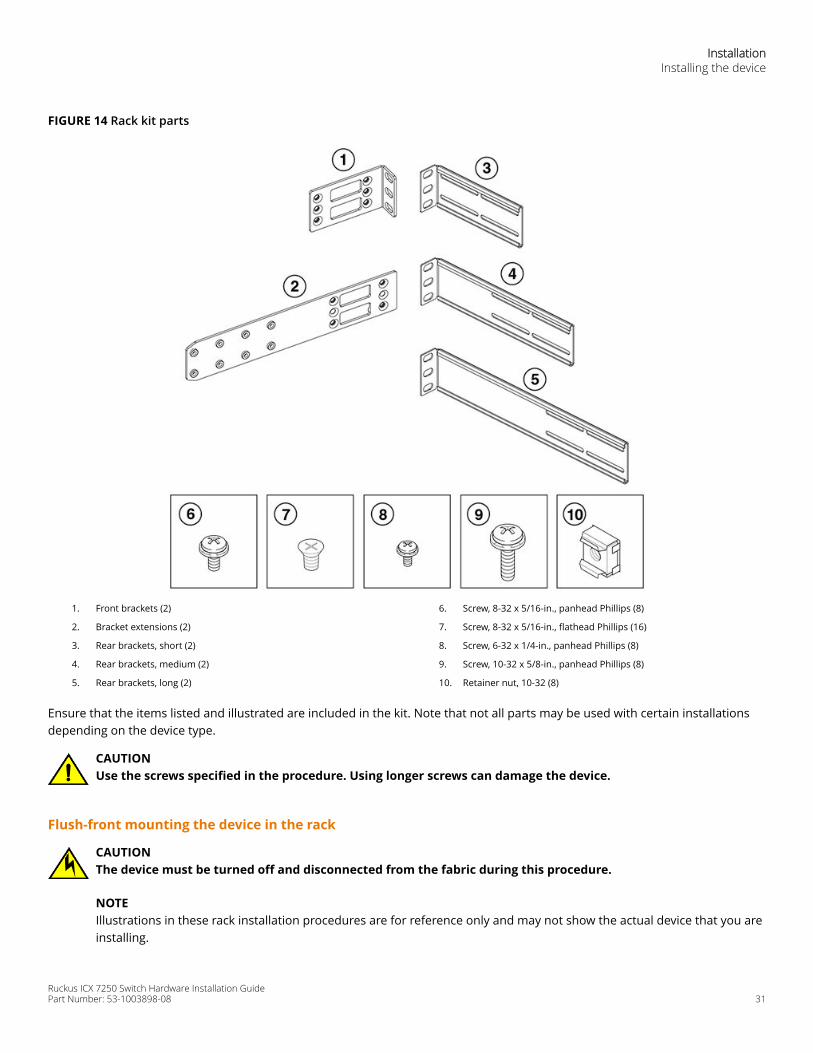
FIGURE 14 Rack kit parts
1. Front brackets (2)
2. Bracket extensions (2)
3. Rear brackets, short (2)
4. Rear brackets, medium (2)
5. Rear brackets, long (2)
6. Screw, 8-32 x 5/16-in., panhead Phillips (8)
7. Screw, 8-32 x 5/16-in., flathead Phillips (16)
8. Screw, 6-32 x 1/4-in., panhead Phillips (8)
9. Screw, 10-32 x 5/8-in., panhead Phillips (8)
10. Retainer nut, 10-32 (8)
Ensure that the items listed and illustrated are included in the kit. Note that not all parts may be used with certain installationsdepending on the device type.
CAUTIONUse the screws specified in the procedure. Using longer screws can damage the device.
Flush-front mounting the device in the rack
CAUTIONThe device must be turned off and disconnected from the fabric during this procedure.
NOTEIllustrations in these rack installation procedures are for reference only and may not show the actual device that you areinstalling.
InstallationInstalling the device
Ruckus ICX 7250 Switch Hardware Installation GuidePart Number: 53-1003898-08 31
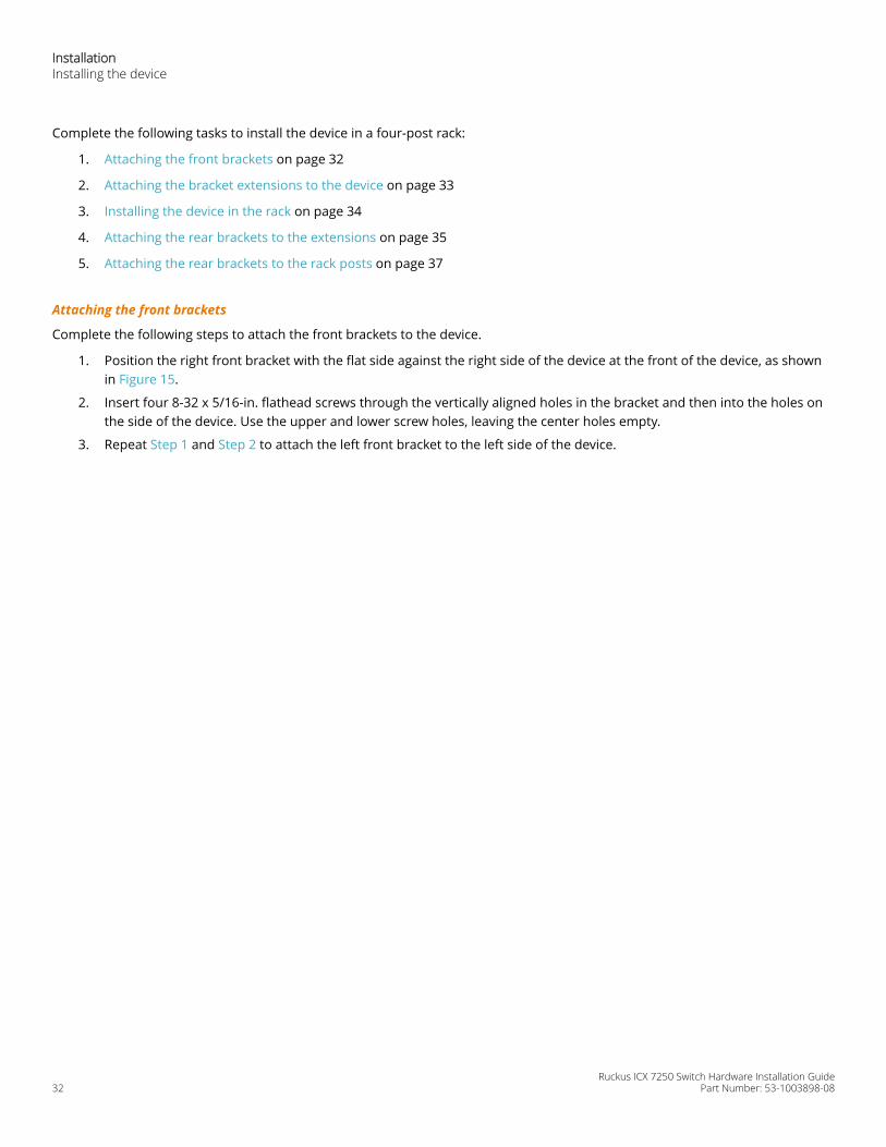
Complete the following tasks to install the device in a four-post rack:
1. Attaching the front brackets on page 32
2. Attaching the bracket extensions to the device on page 33
3. Installing the device in the rack on page 34
4. Attaching the rear brackets to the extensions on page 35
5. Attaching the rear brackets to the rack posts on page 37
Attaching the front brackets
Complete the following steps to attach the front brackets to the device.
1. Position the right front bracket with the flat side against the right side of the device at the front of the device, as shownin Figure 15.
2. Insert four 8-32 x 5/16-in. flathead screws through the vertically aligned holes in the bracket and then into the holes onthe side of the device. Use the upper and lower screw holes, leaving the center holes empty.
3. Repeat Step 1 and Step 2 to attach the left front bracket to the left side of the device.
InstallationInstalling the device
Ruckus ICX 7250 Switch Hardware Installation Guide32 Part Number: 53-1003898-08
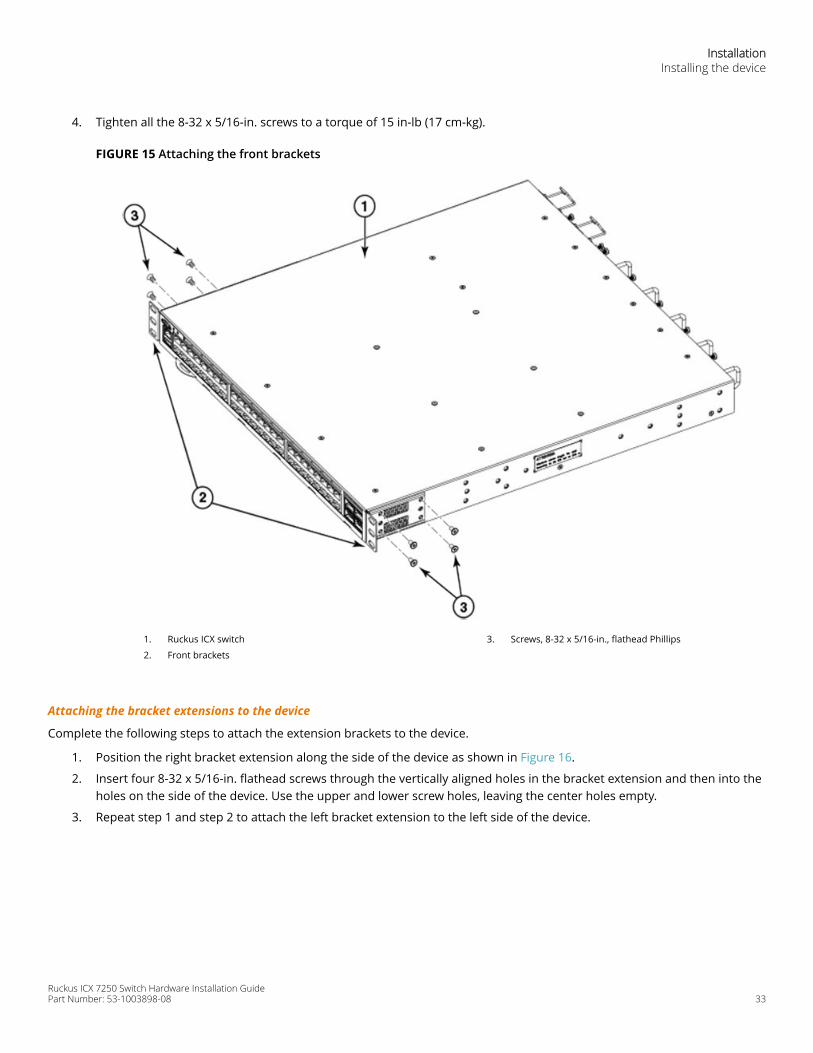
4. Tighten all the 8-32 x 5/16-in. screws to a torque of 15 in-lb (17 cm-kg).
FIGURE 15 Attaching the front brackets
1. Ruckus ICX switch
2. Front brackets
3. Screws, 8-32 x 5/16-in., flathead Phillips
Attaching the bracket extensions to the device
Complete the following steps to attach the extension brackets to the device.
1. Position the right bracket extension along the side of the device as shown in Figure 16.
2. Insert four 8-32 x 5/16-in. flathead screws through the vertically aligned holes in the bracket extension and then into theholes on the side of the device. Use the upper and lower screw holes, leaving the center holes empty.
3. Repeat step 1 and step 2 to attach the left bracket extension to the left side of the device.
InstallationInstalling the device
Ruckus ICX 7250 Switch Hardware Installation GuidePart Number: 53-1003898-08 33
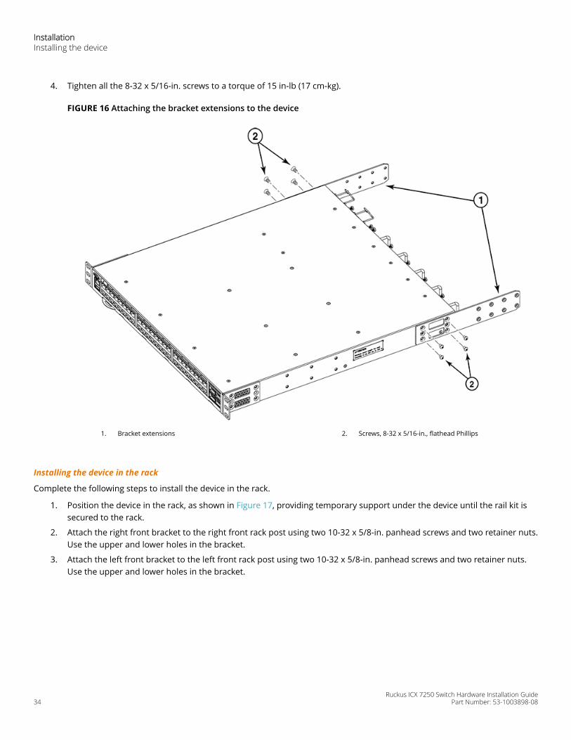
4. Tighten all the 8-32 x 5/16-in. screws to a torque of 15 in-lb (17 cm-kg).
FIGURE 16 Attaching the bracket extensions to the device
1. Bracket extensions 2. Screws, 8-32 x 5/16-in., flathead Phillips
Installing the device in the rack
Complete the following steps to install the device in the rack.
1. Position the device in the rack, as shown in Figure 17, providing temporary support under the device until the rail kit issecured to the rack.
2. Attach the right front bracket to the right front rack post using two 10-32 x 5/8-in. panhead screws and two retainer nuts.Use the upper and lower holes in the bracket.
3. Attach the left front bracket to the left front rack post using two 10-32 x 5/8-in. panhead screws and two retainer nuts.Use the upper and lower holes in the bracket.
InstallationInstalling the device
Ruckus ICX 7250 Switch Hardware Installation Guide34 Part Number: 53-1003898-08
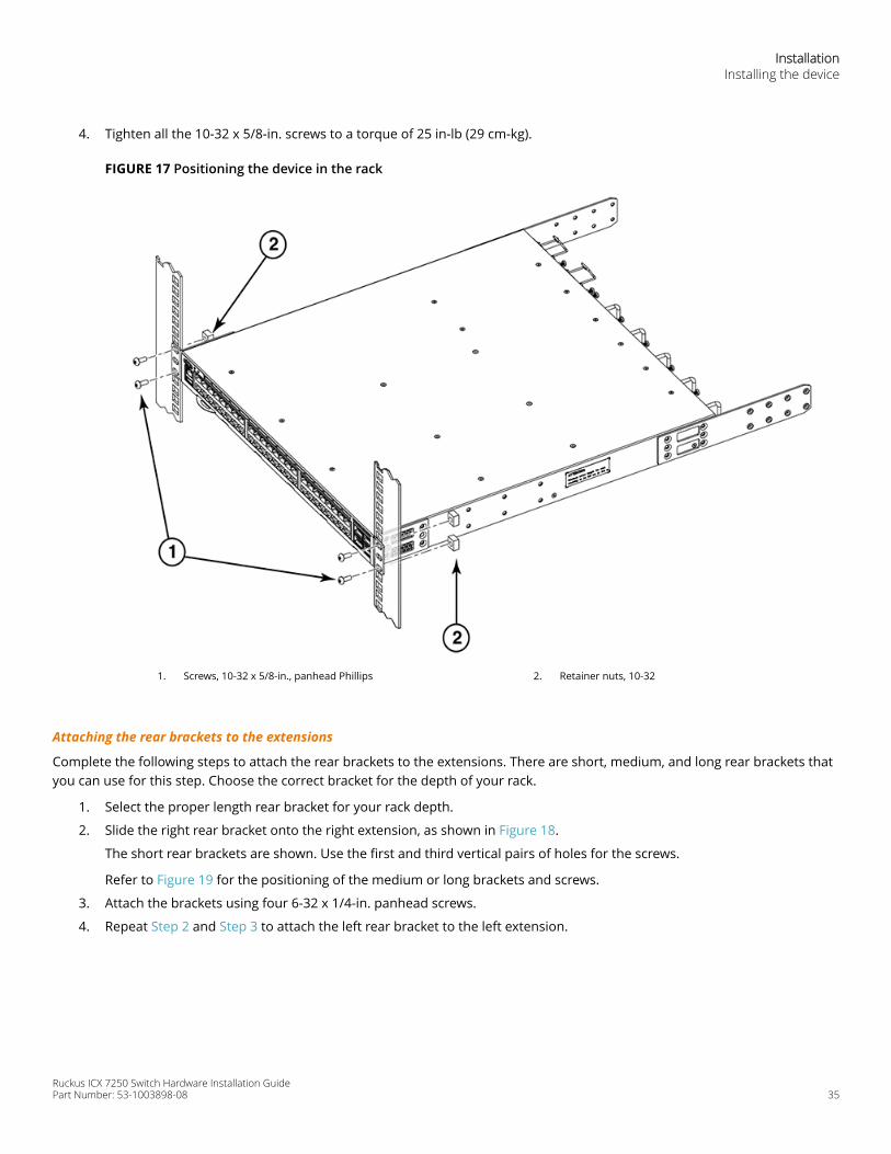
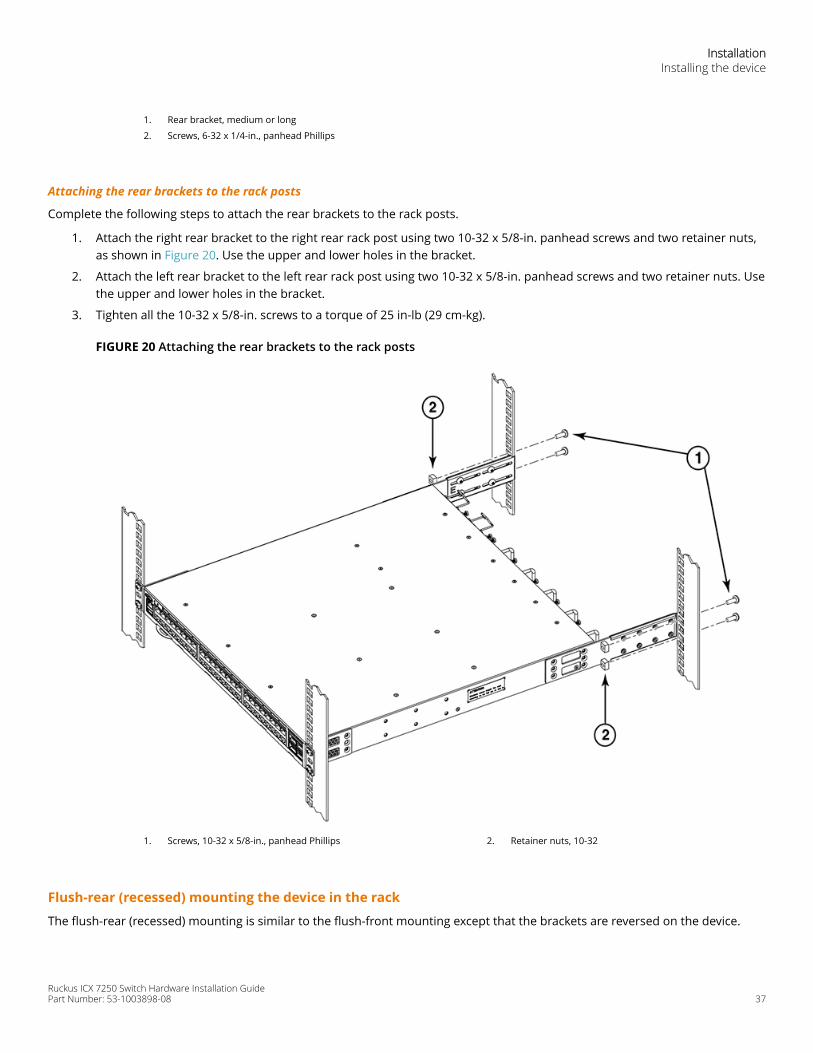
4. Tighten all the 10-32 x 5/8-in. screws to a torque of 25 in-lb (29 cm-kg).
FIGURE 17 Positioning the device in the rack
1. Screws, 10-32 x 5/8-in., panhead Phillips 2. Retainer nuts, 10-32
Attaching the rear brackets to the extensions
Complete the following steps to attach the rear brackets to the extensions. There are short, medium, and long rear brackets thatyou can use for this step. Choose the correct bracket for the depth of your rack.
1. Select the proper length rear bracket for your rack depth.
2. Slide the right rear bracket onto the right extension, as shown in Figure 18.
The short rear brackets are shown. Use the first and third vertical pairs of holes for the screws.
Refer to Figure 19 for the positioning of the medium or long brackets and screws.
3. Attach the brackets using four 6-32 x 1/4-in. panhead screws.
4. Repeat Step 2 and Step 3 to attach the left rear bracket to the left extension.
InstallationInstalling the device
Ruckus ICX 7250 Switch Hardware Installation GuidePart Number: 53-1003898-08 35
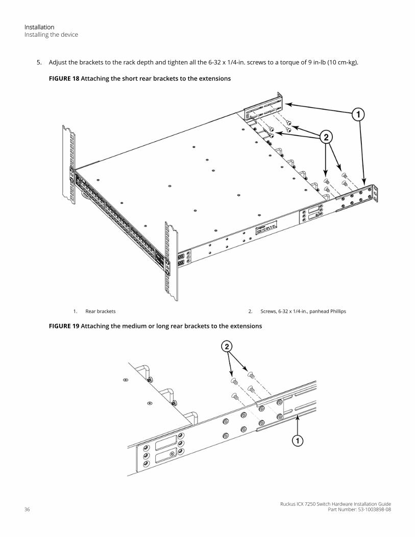
5. Adjust the brackets to the rack depth and tighten all the 6-32 x 1/4-in. screws to a torque of 9 in-lb (10 cm-kg).
FIGURE 18 Attaching the short rear brackets to the extensions
1. Rear brackets 2. Screws, 6-32 x 1/4-in., panhead Phillips
FIGURE 19 Attaching the medium or long rear brackets to the extensions
InstallationInstalling the device
Ruckus ICX 7250 Switch Hardware Installation Guide36 Part Number: 53-1003898-08
1. Rear bracket, medium or long
2. Screws, 6-32 x 1/4-in., panhead Phillips
Attaching the rear brackets to the rack posts
Complete the following steps to attach the rear brackets to the rack posts.
1. Attach the right rear bracket to the right rear rack post using two 10-32 x 5/8-in. panhead screws and two retainer nuts,as shown in Figure 20. Use the upper and lower holes in the bracket.
2. Attach the left rear bracket to the left rear rack post using two 10-32 x 5/8-in. panhead screws and two retainer nuts. Usethe upper and lower holes in the bracket.
3. Tighten all the 10-32 x 5/8-in. screws to a torque of 25 in-lb (29 cm-kg).
FIGURE 20 Attaching the rear brackets to the rack posts
1. Screws, 10-32 x 5/8-in., panhead Phillips 2. Retainer nuts, 10-32
Flush-rear (recessed) mounting the device in the rack
The flush-rear (recessed) mounting is similar to the flush-front mounting except that the brackets are reversed on the device.
InstallationInstalling the device
Ruckus ICX 7250 Switch Hardware Installation GuidePart Number: 53-1003898-08 37
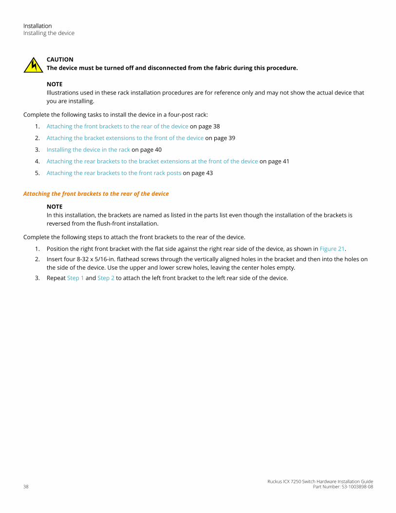
CAUTIONThe device must be turned off and disconnected from the fabric during this procedure.
NOTEIllustrations used in these rack installation procedures are for reference only and may not show the actual device thatyou are installing.
Complete the following tasks to install the device in a four-post rack:
1. Attaching the front brackets to the rear of the device on page 38
2. Attaching the bracket extensions to the front of the device on page 39
3. Installing the device in the rack on page 40
4. Attaching the rear brackets to the bracket extensions at the front of the device on page 41
5. Attaching the rear brackets to the front rack posts on page 43
Attaching the front brackets to the rear of the device
NOTEIn this installation, the brackets are named as listed in the parts list even though the installation of the brackets isreversed from the flush-front installation.
Complete the following steps to attach the front brackets to the rear of the device.
1. Position the right front bracket with the flat side against the right rear side of the device, as shown in Figure 21.
2. Insert four 8-32 x 5/16-in. flathead screws through the vertically aligned holes in the bracket and then into the holes onthe side of the device. Use the upper and lower screw holes, leaving the center holes empty.
3. Repeat Step 1 and Step 2 to attach the left front bracket to the left rear side of the device.
InstallationInstalling the device
Ruckus ICX 7250 Switch Hardware Installation Guide38 Part Number: 53-1003898-08
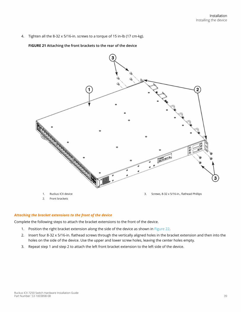
4. Tighten all the 8-32 x 5/16-in. screws to a torque of 15 in-lb (17 cm-kg).
FIGURE 21 Attaching the front brackets to the rear of the device
1. Ruckus ICX device
2. Front brackets
3. Screws, 8-32 x 5/16-in., flathead Phillips
Attaching the bracket extensions to the front of the device
Complete the following steps to attach the bracket extensions to the front of the device.
1. Position the right bracket extension along the side of the device as shown in Figure 22.
2. Insert four 8-32 x 5/16-in. flathead screws through the vertically aligned holes in the bracket extension and then into theholes on the side of the device. Use the upper and lower screw holes, leaving the center holes empty.
3. Repeat step 1 and step 2 to attach the left front bracket extension to the left side of the device.
InstallationInstalling the device
Ruckus ICX 7250 Switch Hardware Installation GuidePart Number: 53-1003898-08 39
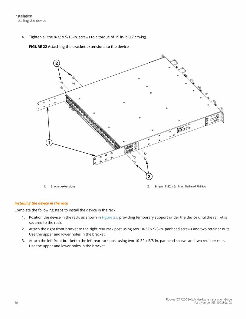
4. Tighten all the 8-32 x 5/16-in. screws to a torque of 15 in-lb (17 cm-kg).
FIGURE 22 Attaching the bracket extensions to the device
1. Bracket extensions 2. Screws, 8-32 x 5/16-in., flathead Phillips
Installing the device in the rack
Complete the following steps to install the device in the rack.
1. Position the device in the rack, as shown in Figure 23, providing temporary support under the device until the rail kit issecured to the rack.
2. Attach the right front bracket to the right rear rack post using two 10-32 x 5/8-in. panhead screws and two retainer nuts.Use the upper and lower holes in the bracket.
3. Attach the left front bracket to the left rear rack post using two 10-32 x 5/8-in. panhead screws and two retainer nuts.Use the upper and lower holes in the bracket.
InstallationInstalling the device
Ruckus ICX 7250 Switch Hardware Installation Guide40 Part Number: 53-1003898-08
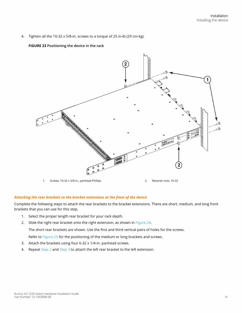
4. Tighten all the 10-32 x 5/8-in. screws to a torque of 25 in-lb (29 cm-kg).
FIGURE 23 Positioning the device in the rack
1. Screws, 10-32 x 5/8-in., panhead Phillips 2. Retainer nuts, 10-32
Attaching the rear brackets to the bracket extensions at the front of the device
Complete the following steps to attach the rear brackets to the bracket extensions. There are short, medium, and long frontbrackets that you can use for this step.
1. Select the proper length rear bracket for your rack depth.
2. Slide the right rear bracket onto the right extension, as shown in Figure 24.
The short rear brackets are shown. Use the first and third vertical pairs of holes for the screws.
Refer to Figure 25 for the positioning of the medium or long brackets and screws.
3. Attach the brackets using four 6-32 x 1/4-in. panhead screws.
4. Repeat Step 2 and Step 3 to attach the left rear bracket to the left extension.
InstallationInstalling the device
Ruckus ICX 7250 Switch Hardware Installation GuidePart Number: 53-1003898-08 41
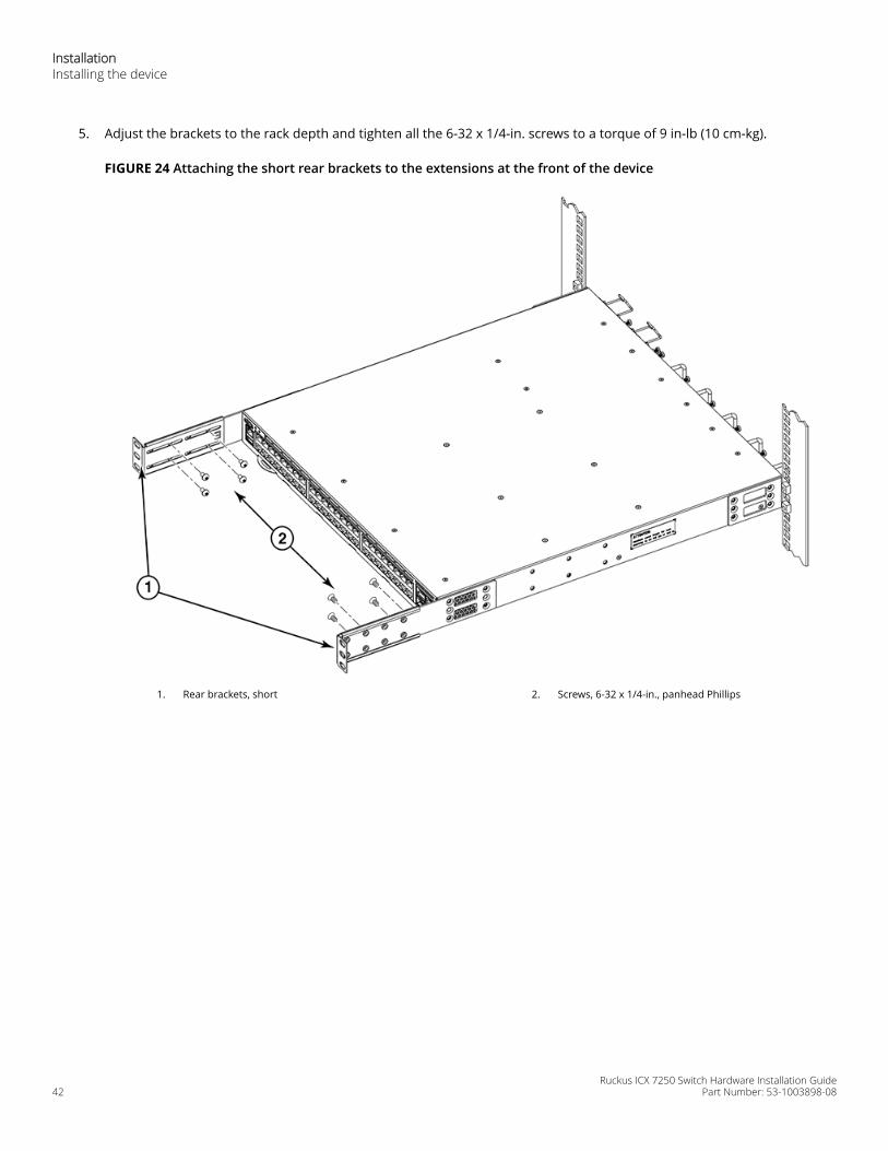
5. Adjust the brackets to the rack depth and tighten all the 6-32 x 1/4-in. screws to a torque of 9 in-lb (10 cm-kg).
FIGURE 24 Attaching the short rear brackets to the extensions at the front of the device
1. Rear brackets, short 2. Screws, 6-32 x 1/4-in., panhead Phillips
InstallationInstalling the device
Ruckus ICX 7250 Switch Hardware Installation Guide42 Part Number: 53-1003898-08
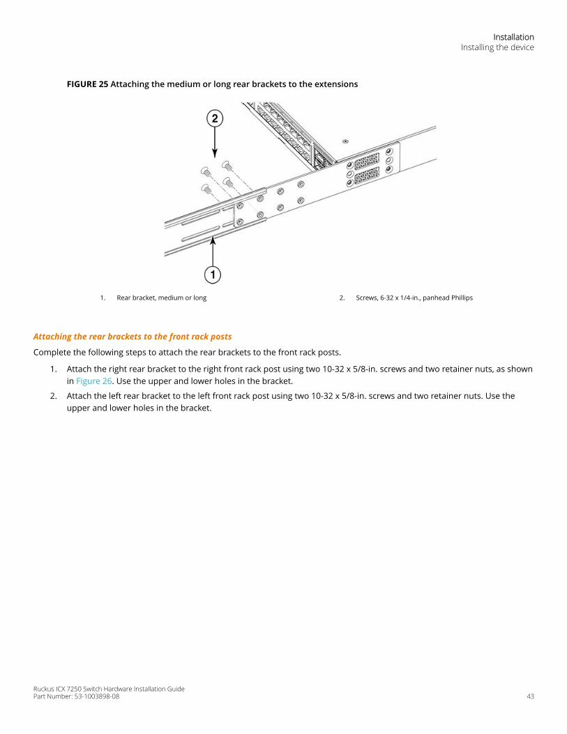
FIGURE 25 Attaching the medium or long rear brackets to the extensions
1. Rear bracket, medium or long 2. Screws, 6-32 x 1/4-in., panhead Phillips
Attaching the rear brackets to the front rack posts
Complete the following steps to attach the rear brackets to the front rack posts.
1. Attach the right rear bracket to the right front rack post using two 10-32 x 5/8-in. screws and two retainer nuts, as shownin Figure 26. Use the upper and lower holes in the bracket.
2. Attach the left rear bracket to the left front rack post using two 10-32 x 5/8-in. screws and two retainer nuts. Use theupper and lower holes in the bracket.
InstallationInstalling the device
Ruckus ICX 7250 Switch Hardware Installation GuidePart Number: 53-1003898-08 43
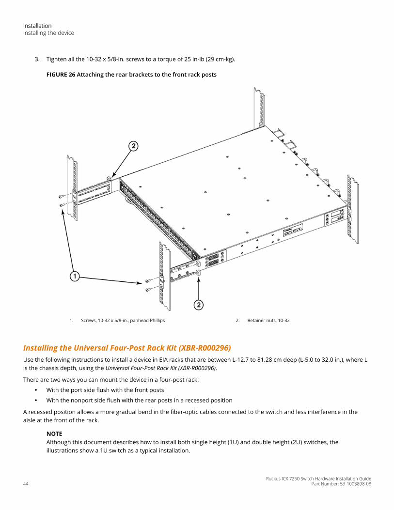
3. Tighten all the 10-32 x 5/8-in. screws to a torque of 25 in-lb (29 cm-kg).
FIGURE 26 Attaching the rear brackets to the front rack posts
1. Screws, 10-32 x 5/8-in., panhead Phillips 2. Retainer nuts, 10-32
Installing the Universal Four-Post Rack Kit (XBR-R000296)Use the following instructions to install a device in EIA racks that are between L-12.7 to 81.28 cm deep (L-5.0 to 32.0 in.), where Lis the chassis depth, using the Universal Four-Post Rack Kit (XBR-R000296).
There are two ways you can mount the device in a four-post rack:
• With the port side flush with the front posts
• With the nonport side flush with the rear posts in a recessed position
A recessed position allows a more gradual bend in the fiber-optic cables connected to the switch and less interference in theaisle at the front of the rack.
NOTEAlthough this document describes how to install both single height (1U) and double height (2U) switches, theillustrations show a 1U switch as a typical installation.
InstallationInstalling the device
Ruckus ICX 7250 Switch Hardware Installation Guide44 Part Number: 53-1003898-08
NOTEHardware devices illustrated in these procedures are only for reference and may not depict the device you are installinginto the rack.
Installation requirements
Provide space in an EIA rack with the following minimum and maximum distances between the front and back posts.
NOTEFor 1U and 2U devices, two people are required to install the device in a rack. One person holds the device, while theother screws in the front and rear "L" brackets.
TABLE 9 Space requirementsChassis with port-side side vents
Notes Chassis depth Minimum rack depth Maximum rack depth
No Applicable to port-side and nonport-side flushmounts.
L L-12.7 cm (L-5 in.) 81.28 cm (32 in.)
Yes Applicable to port-side flush mounts. L L-12.7 cm (L-5 in.) 81.28 cm (32 in.)
Yes Applicable to nonport-side flush mounts. L L 81.28 cm (32 in.)
Note that if chassis depth (L) is less than 40.64 cm (16 in.), the chassis will not fit into a rack with a maximum depth of 81.28 cm(32 in.) using the universal four-post rack kit. The maximum rack depth for a chassis less than 40.64 cm (16 in.) is 81.28 cm (32 in.)minus the difference between the chassis depth and 40.64 cm (16 in.). For example, a chassis with a depth (L) of 35.56 cm (14 in.)is 5.08 cm (2 in.) smaller than 40.64 cm (16 in.), so it will install into a rack with a maximum depth of 81.28 cm (32 in.) - 5.08 cm (2in.) = 76.2 cm (30 in.).
Review the installation and facility requirements for your product before mounting the device . Refer to the Hardware InstallationGuide for your product for more information.
Time and items required
Allow 15 to 30 minutes to complete the installation.
The following items are required to install the device using the Universal Four-Post Rack Kit:
• #2 Phillips torque screwdriver
• 1/4-inch slotted-blade torque screwdriver
CAUTIONUse the screws specified in the procedure. Using longer screws can damage the device.
Flush-front mounting
CAUTIONThe device must be turned off and disconnected from the fabric during this procedure.
NOTEThe illustrations in the rack installation procedures show a 1U device, but the instructions are the same for a 2U device.The illustrations in the rack installation procedures are for reference only and may not show the actual device.
InstallationInstalling the device
Ruckus ICX 7250 Switch Hardware Installation GuidePart Number: 53-1003898-08 45
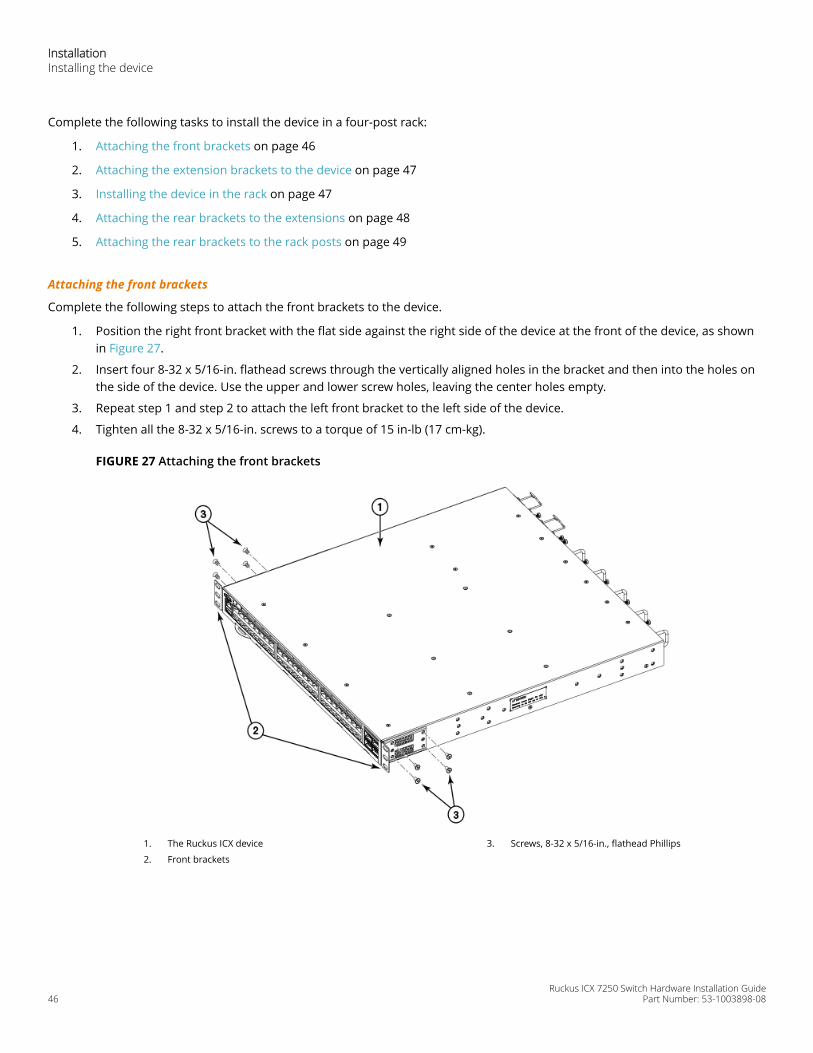
Complete the following tasks to install the device in a four-post rack:
1. Attaching the front brackets on page 46
2. Attaching the extension brackets to the device on page 47
3. Installing the device in the rack on page 47
4. Attaching the rear brackets to the extensions on page 48
5. Attaching the rear brackets to the rack posts on page 49
Attaching the front brackets
Complete the following steps to attach the front brackets to the device.
1. Position the right front bracket with the flat side against the right side of the device at the front of the device, as shownin Figure 27.
2. Insert four 8-32 x 5/16-in. flathead screws through the vertically aligned holes in the bracket and then into the holes onthe side of the device. Use the upper and lower screw holes, leaving the center holes empty.
3. Repeat step 1 and step 2 to attach the left front bracket to the left side of the device.
4. Tighten all the 8-32 x 5/16-in. screws to a torque of 15 in-lb (17 cm-kg).
FIGURE 27 Attaching the front brackets
1. The Ruckus ICX device
2. Front brackets
3. Screws, 8-32 x 5/16-in., flathead Phillips
InstallationInstalling the device
Ruckus ICX 7250 Switch Hardware Installation Guide46 Part Number: 53-1003898-08
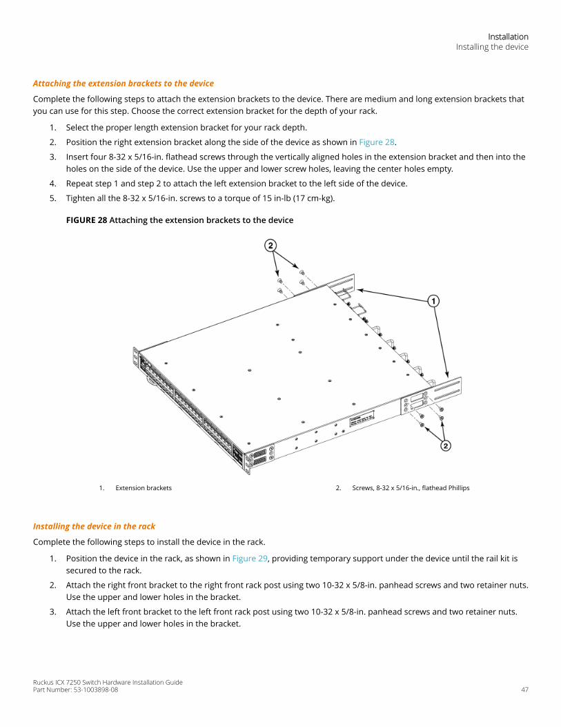
Attaching the extension brackets to the device
Complete the following steps to attach the extension brackets to the device. There are medium and long extension brackets thatyou can use for this step. Choose the correct extension bracket for the depth of your rack.
1. Select the proper length extension bracket for your rack depth.
2. Position the right extension bracket along the side of the device as shown in Figure 28.
3. Insert four 8-32 x 5/16-in. flathead screws through the vertically aligned holes in the extension bracket and then into theholes on the side of the device. Use the upper and lower screw holes, leaving the center holes empty.
4. Repeat step 1 and step 2 to attach the left extension bracket to the left side of the device.
5. Tighten all the 8-32 x 5/16-in. screws to a torque of 15 in-lb (17 cm-kg).
FIGURE 28 Attaching the extension brackets to the device
1. Extension brackets 2. Screws, 8-32 x 5/16-in., flathead Phillips
Installing the device in the rack
Complete the following steps to install the device in the rack.
1. Position the device in the rack, as shown in Figure 29, providing temporary support under the device until the rail kit issecured to the rack.
2. Attach the right front bracket to the right front rack post using two 10-32 x 5/8-in. panhead screws and two retainer nuts.Use the upper and lower holes in the bracket.
3. Attach the left front bracket to the left front rack post using two 10-32 x 5/8-in. panhead screws and two retainer nuts.Use the upper and lower holes in the bracket.
InstallationInstalling the device
Ruckus ICX 7250 Switch Hardware Installation GuidePart Number: 53-1003898-08 47
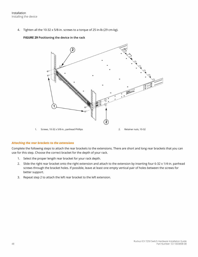
4. Tighten all the 10-32 x 5/8-in. screws to a torque of 25 in-lb (29 cm-kg).
FIGURE 29 Positioning the device in the rack
1. Screws, 10-32 x 5/8-in., panhead Phillips 2. Retainer nuts, 10-32
Attaching the rear brackets to the extensions
Complete the following steps to attach the rear brackets to the extensions. There are short and long rear brackets that you canuse for this step. Choose the correct bracket for the depth of your rack.
1. Select the proper length rear bracket for your rack depth.
2. Slide the right rear bracket onto the right extension and attach to the extension by inserting four 6-32 x 1/4-in. panheadscrews through the bracket holes. If possible, leave at least one empty vertical pair of holes between the screws forbetter support.
3. Repeat step 2 to attach the left rear bracket to the left extension.
InstallationInstalling the device
Ruckus ICX 7250 Switch Hardware Installation Guide48 Part Number: 53-1003898-08
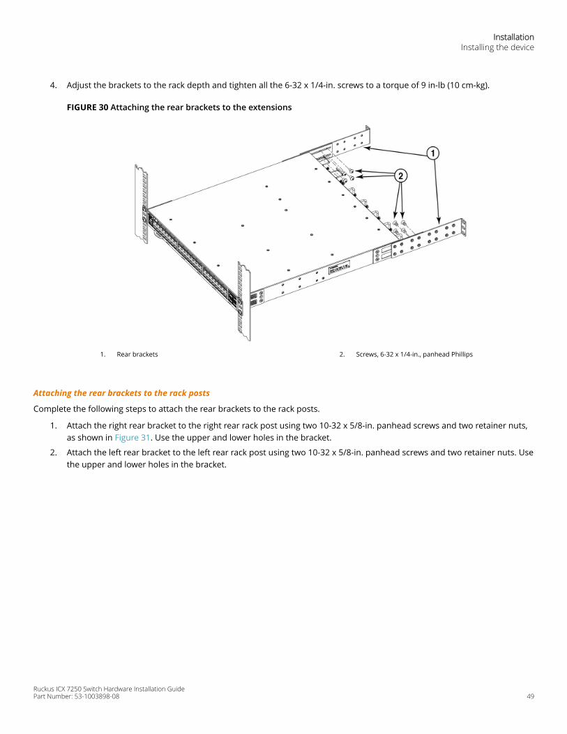
4. Adjust the brackets to the rack depth and tighten all the 6-32 x 1/4-in. screws to a torque of 9 in-lb (10 cm-kg).
FIGURE 30 Attaching the rear brackets to the extensions
1. Rear brackets 2. Screws, 6-32 x 1/4-in., panhead Phillips
Attaching the rear brackets to the rack posts
Complete the following steps to attach the rear brackets to the rack posts.
1. Attach the right rear bracket to the right rear rack post using two 10-32 x 5/8-in. panhead screws and two retainer nuts,as shown in Figure 31. Use the upper and lower holes in the bracket.
2. Attach the left rear bracket to the left rear rack post using two 10-32 x 5/8-in. panhead screws and two retainer nuts. Usethe upper and lower holes in the bracket.
InstallationInstalling the device
Ruckus ICX 7250 Switch Hardware Installation GuidePart Number: 53-1003898-08 49
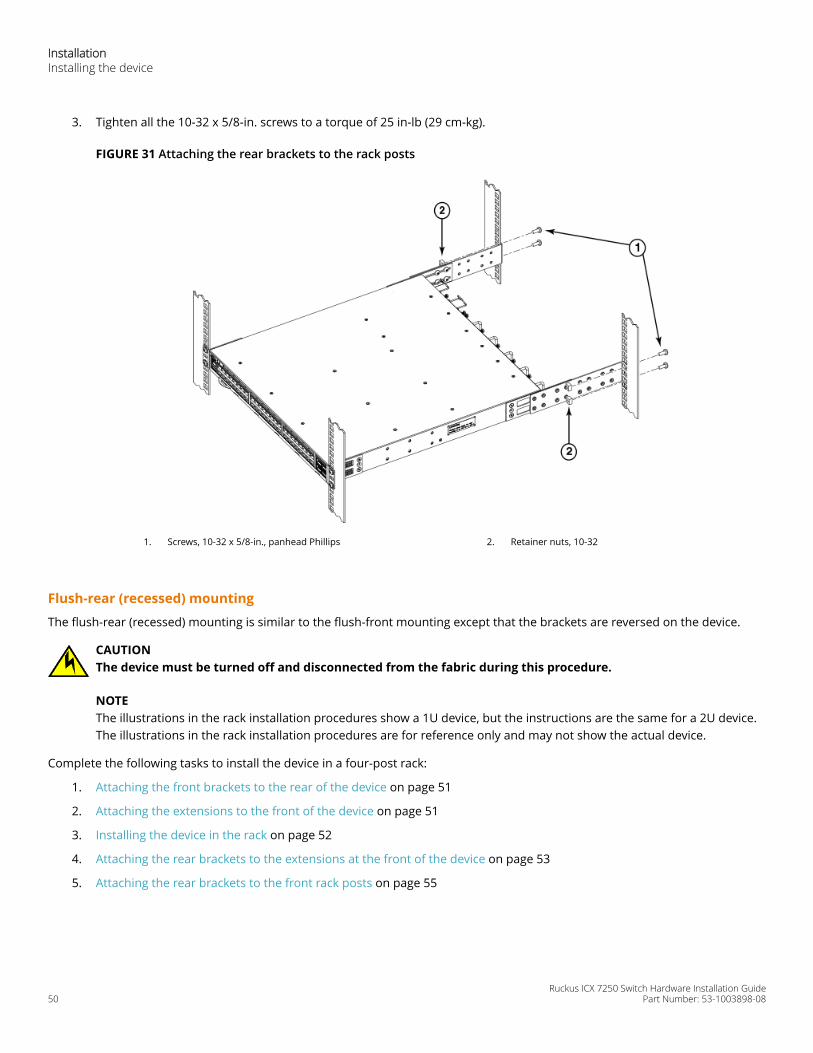
3. Tighten all the 10-32 x 5/8-in. screws to a torque of 25 in-lb (29 cm-kg).
FIGURE 31 Attaching the rear brackets to the rack posts
1. Screws, 10-32 x 5/8-in., panhead Phillips 2. Retainer nuts, 10-32
Flush-rear (recessed) mounting
The flush-rear (recessed) mounting is similar to the flush-front mounting except that the brackets are reversed on the device.
CAUTIONThe device must be turned off and disconnected from the fabric during this procedure.
NOTEThe illustrations in the rack installation procedures show a 1U device, but the instructions are the same for a 2U device.The illustrations in the rack installation procedures are for reference only and may not show the actual device.
Complete the following tasks to install the device in a four-post rack:
1. Attaching the front brackets to the rear of the device on page 51
2. Attaching the extensions to the front of the device on page 51
3. Installing the device in the rack on page 52
4. Attaching the rear brackets to the extensions at the front of the device on page 53
5. Attaching the rear brackets to the front rack posts on page 55
InstallationInstalling the device
Ruckus ICX 7250 Switch Hardware Installation Guide50 Part Number: 53-1003898-08
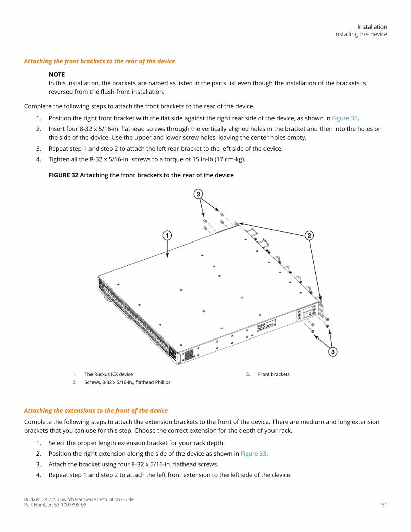
Attaching the front brackets to the rear of the device
NOTEIn this installation, the brackets are named as listed in the parts list even though the installation of the brackets isreversed from the flush-front installation.
Complete the following steps to attach the front brackets to the rear of the device.
1. Position the right front bracket with the flat side against the right rear side of the device, as shown in Figure 32.
2. Insert four 8-32 x 5/16-in. flathead screws through the vertically aligned holes in the bracket and then into the holes onthe side of the device. Use the upper and lower screw holes, leaving the center holes empty.
3. Repeat step 1 and step 2 to attach the left rear bracket to the left side of the device.
4. Tighten all the 8-32 x 5/16-in. screws to a torque of 15 in-lb (17 cm-kg).
FIGURE 32 Attaching the front brackets to the rear of the device
1. The Ruckus ICX device
2. Screws, 8-32 x 5/16-in., flathead Phillips
3. Front brackets
Attaching the extensions to the front of the device
Complete the following steps to attach the extension brackets to the front of the device. There are medium and long extensionbrackets that you can use for this step. Choose the correct extension for the depth of your rack.
1. Select the proper length extension bracket for your rack depth.
2. Position the right extension along the side of the device as shown in Figure 33.
3. Attach the bracket using four 8-32 x 5/16-in. flathead screws.
4. Repeat step 1 and step 2 to attach the left front extension to the left side of the device.
InstallationInstalling the device
Ruckus ICX 7250 Switch Hardware Installation GuidePart Number: 53-1003898-08 51
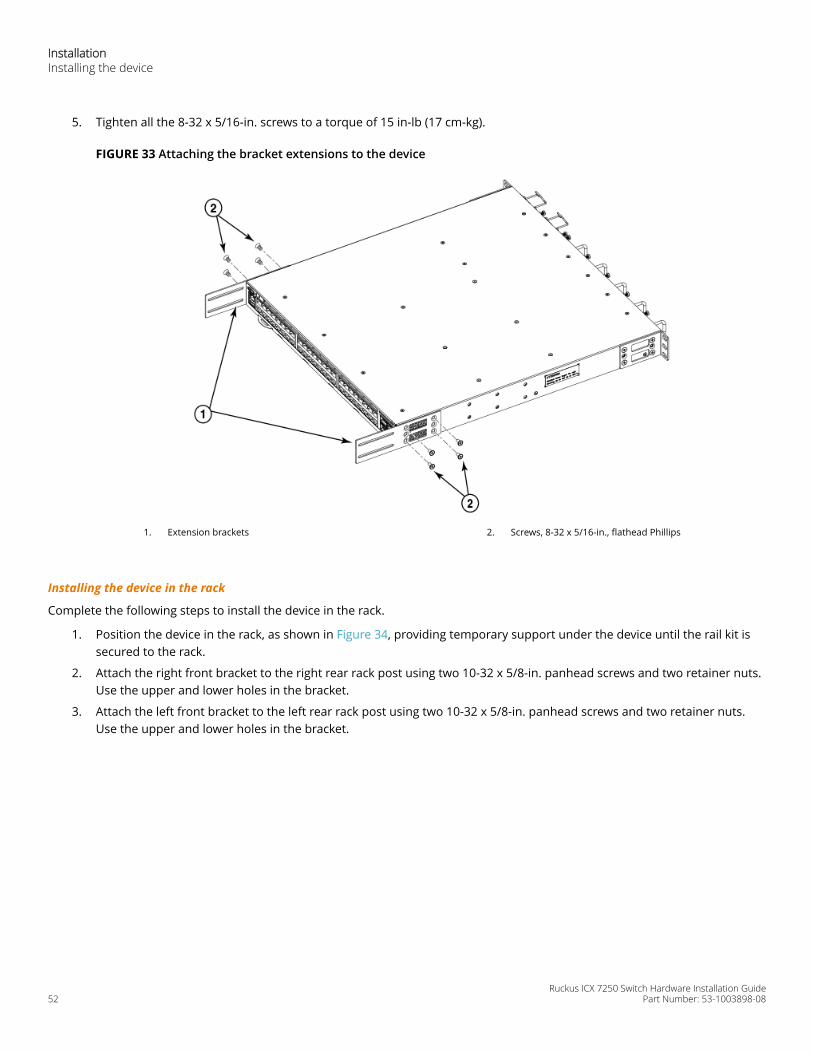
5. Tighten all the 8-32 x 5/16-in. screws to a torque of 15 in-lb (17 cm-kg).
FIGURE 33 Attaching the bracket extensions to the device
1. Extension brackets 2. Screws, 8-32 x 5/16-in., flathead Phillips
Installing the device in the rack
Complete the following steps to install the device in the rack.
1. Position the device in the rack, as shown in Figure 34, providing temporary support under the device until the rail kit issecured to the rack.
2. Attach the right front bracket to the right rear rack post using two 10-32 x 5/8-in. panhead screws and two retainer nuts.Use the upper and lower holes in the bracket.
3. Attach the left front bracket to the left rear rack post using two 10-32 x 5/8-in. panhead screws and two retainer nuts.Use the upper and lower holes in the bracket.
InstallationInstalling the device
Ruckus ICX 7250 Switch Hardware Installation Guide52 Part Number: 53-1003898-08
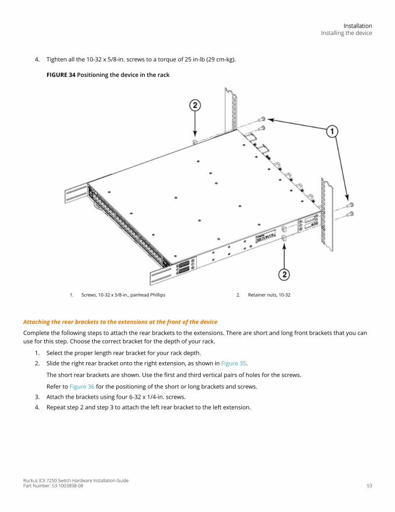
4. Tighten all the 10-32 x 5/8-in. screws to a torque of 25 in-lb (29 cm-kg).
FIGURE 34 Positioning the device in the rack
1. Screws, 10-32 x 5/8-in., panhead Phillips 2. Retainer nuts, 10-32
Attaching the rear brackets to the extensions at the front of the device
Complete the following steps to attach the rear brackets to the extensions. There are short and long front brackets that you canuse for this step. Choose the correct bracket for the depth of your rack.
1. Select the proper length rear bracket for your rack depth.
2. Slide the right rear bracket onto the right extension, as shown in Figure 35.
The short rear brackets are shown. Use the first and third vertical pairs of holes for the screws.
Refer to Figure 36 for the positioning of the short or long brackets and screws.
3. Attach the brackets using four 6-32 x 1/4-in. screws.
4. Repeat step 2 and step 3 to attach the left rear bracket to the left extension.
InstallationInstalling the device
Ruckus ICX 7250 Switch Hardware Installation GuidePart Number: 53-1003898-08 53
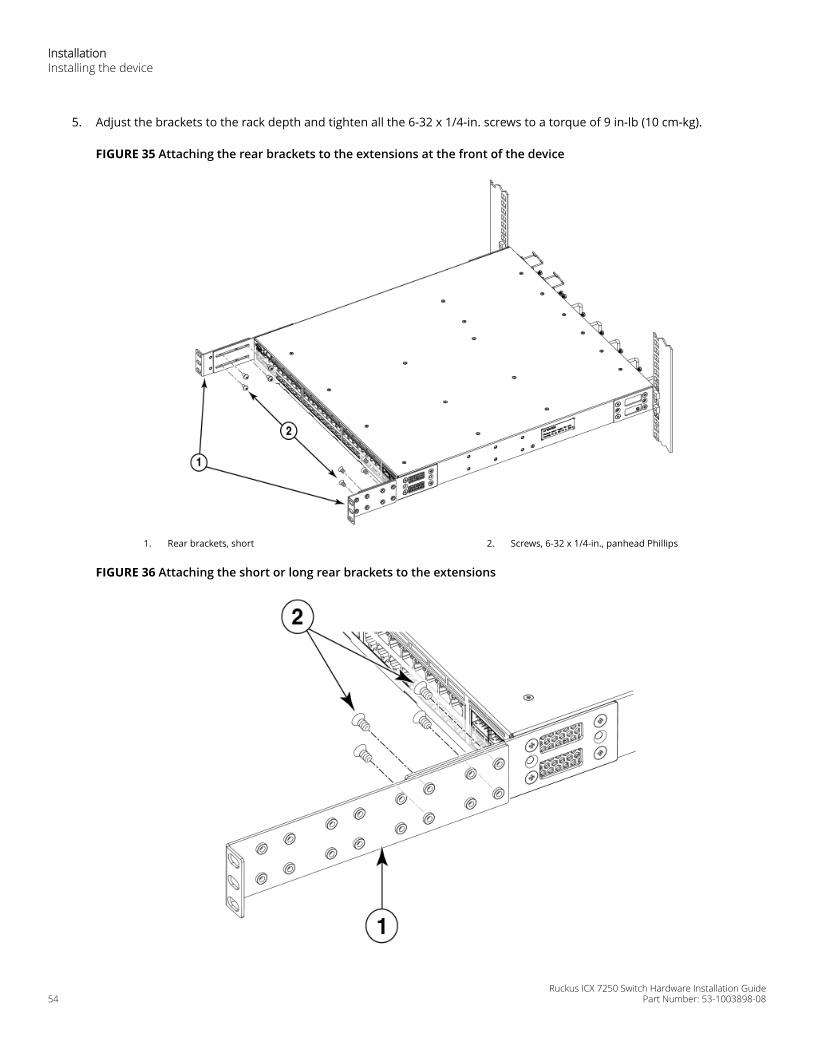
5. Adjust the brackets to the rack depth and tighten all the 6-32 x 1/4-in. screws to a torque of 9 in-lb (10 cm-kg).
FIGURE 35 Attaching the rear brackets to the extensions at the front of the device
1. Rear brackets, short 2. Screws, 6-32 x 1/4-in., panhead Phillips
FIGURE 36 Attaching the short or long rear brackets to the extensions
InstallationInstalling the device
Ruckus ICX 7250 Switch Hardware Installation Guide54 Part Number: 53-1003898-08
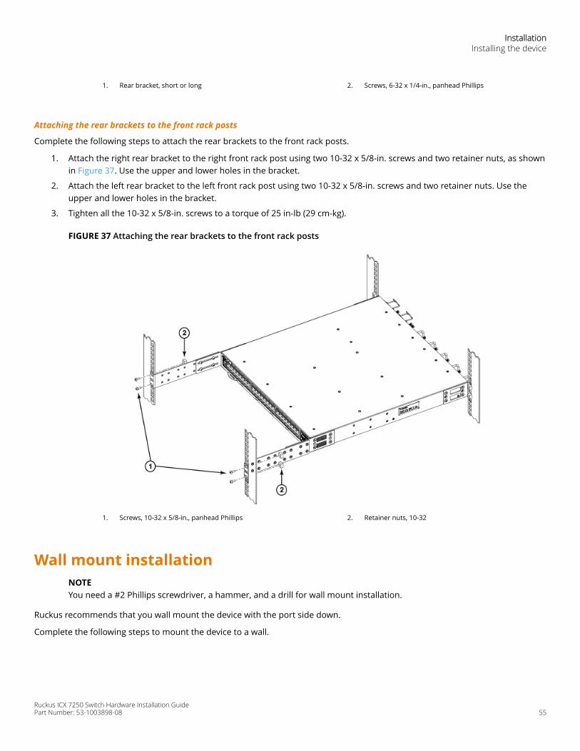
1. Rear bracket, short or long 2. Screws, 6-32 x 1/4-in., panhead Phillips
Attaching the rear brackets to the front rack posts
Complete the following steps to attach the rear brackets to the front rack posts.
1. Attach the right rear bracket to the right front rack post using two 10-32 x 5/8-in. screws and two retainer nuts, as shownin Figure 37. Use the upper and lower holes in the bracket.
2. Attach the left rear bracket to the left front rack post using two 10-32 x 5/8-in. screws and two retainer nuts. Use theupper and lower holes in the bracket.
3. Tighten all the 10-32 x 5/8-in. screws to a torque of 25 in-lb (29 cm-kg).
FIGURE 37 Attaching the rear brackets to the front rack posts
1. Screws, 10-32 x 5/8-in., panhead Phillips 2. Retainer nuts, 10-32
Wall mount installationNOTEYou need a #2 Phillips screwdriver, a hammer, and a drill for wall mount installation.
Ruckus recommends that you wall mount the device with the port side down.
Complete the following steps to mount the device to a wall.
InstallationInstalling the device
Ruckus ICX 7250 Switch Hardware Installation GuidePart Number: 53-1003898-08 55
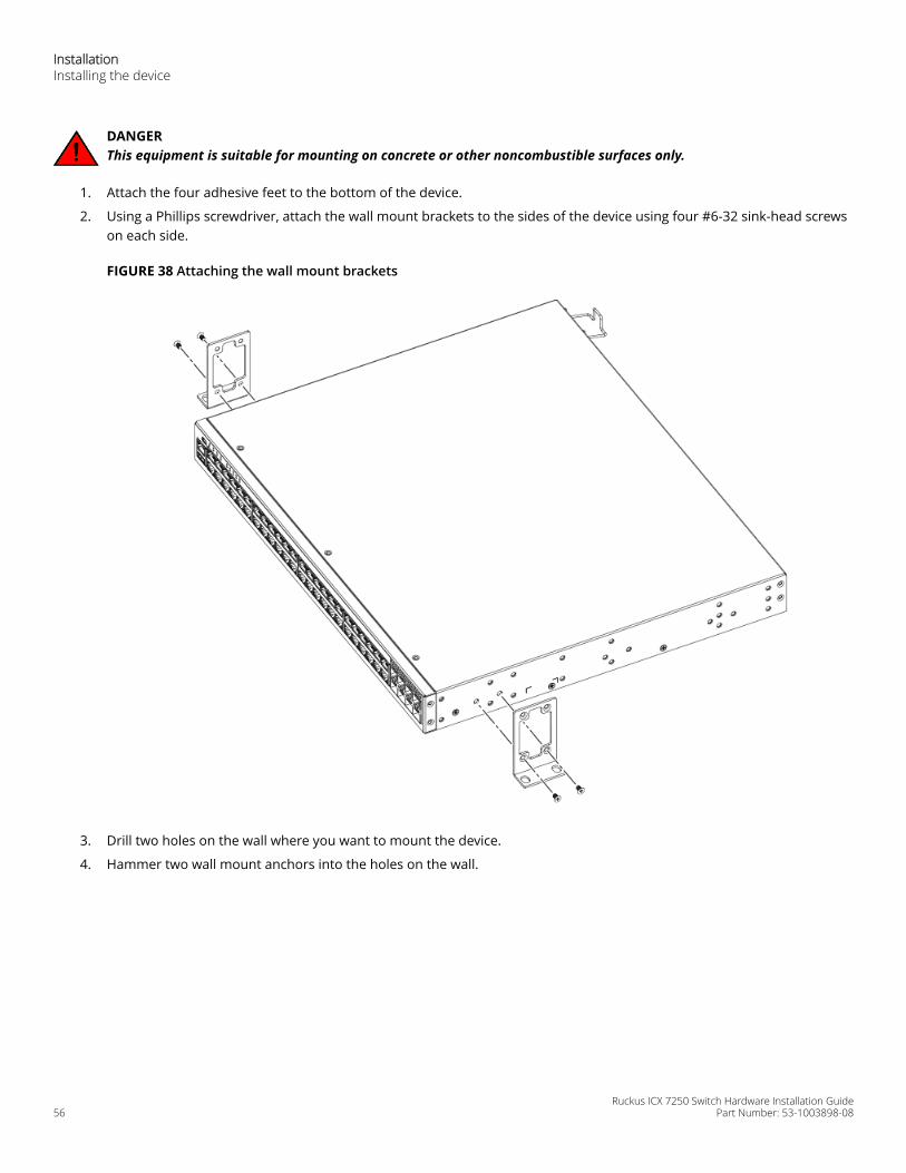
DANGERThis equipment is suitable for mounting on concrete or other noncombustible surfaces only.
1. Attach the four adhesive feet to the bottom of the device.
2. Using a Phillips screwdriver, attach the wall mount brackets to the sides of the device using four #6-32 sink-head screwson each side.
FIGURE 38 Attaching the wall mount brackets
3. Drill two holes on the wall where you want to mount the device.
4. Hammer two wall mount anchors into the holes on the wall.
InstallationInstalling the device
Ruckus ICX 7250 Switch Hardware Installation Guide56 Part Number: 53-1003898-08
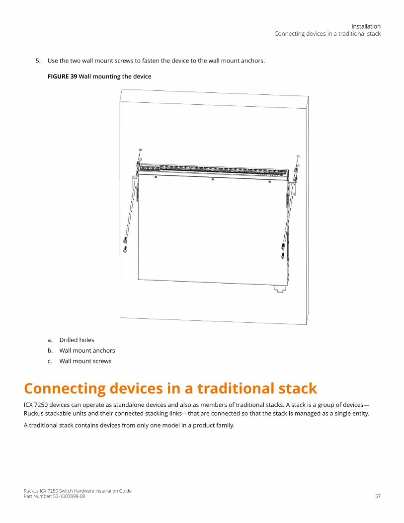
5. Use the two wall mount screws to fasten the device to the wall mount anchors.
FIGURE 39 Wall mounting the device
a. Drilled holes
b. Wall mount anchors
c. Wall mount screws
Connecting devices in a traditional stackICX 7250 devices can operate as standalone devices and also as members of traditional stacks. A stack is a group of devices—Ruckus stackable units and their connected stacking links—that are connected so that the stack is managed as a single entity.
A traditional stack contains devices from only one model in a product family.
InstallationConnecting devices in a traditional stack
Ruckus ICX 7250 Switch Hardware Installation GuidePart Number: 53-1003898-08 57
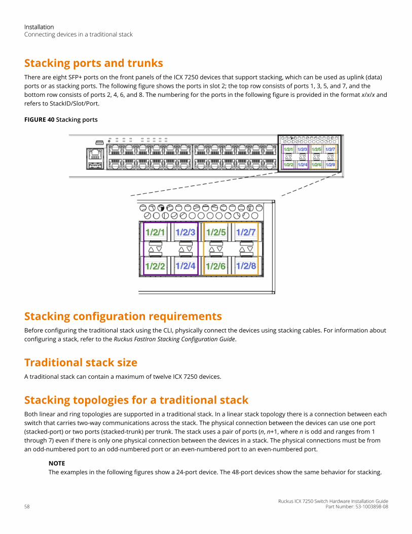
Stacking ports and trunksThere are eight SFP+ ports on the front panels of the ICX 7250 devices that support stacking, which can be used as uplink (data)ports or as stacking ports. The following figure shows the ports in slot 2; the top row consists of ports 1, 3, 5, and 7, and thebottom row consists of ports 2, 4, 6, and 8. The numbering for the ports in the following figure is provided in the format x/x/x andrefers to StackID/Slot/Port.
FIGURE 40 Stacking ports
Stacking configuration requirementsBefore configuring the traditional stack using the CLI, physically connect the devices using stacking cables. For information aboutconfiguring a stack, refer to the Ruckus FastIron Stacking Configuration Guide.
Traditional stack sizeA traditional stack can contain a maximum of twelve ICX 7250 devices.
Stacking topologies for a traditional stackBoth linear and ring topologies are supported in a traditional stack. In a linear stack topology there is a connection between eachswitch that carries two-way communications across the stack. The physical connection between the devices can use one port(stacked-port) or two ports (stacked-trunk) per trunk. The stack uses a pair of ports (n, n+1, where n is odd and ranges from 1through 7) even if there is only one physical connection between the devices in a stack. The physical connections must be froman odd-numbered port to an odd-numbered port or an even-numbered port to an even-numbered port.
NOTEThe examples in the following figures show a 24-port device. The 48-port devices show the same behavior for stacking.
InstallationConnecting devices in a traditional stack
Ruckus ICX 7250 Switch Hardware Installation Guide58 Part Number: 53-1003898-08
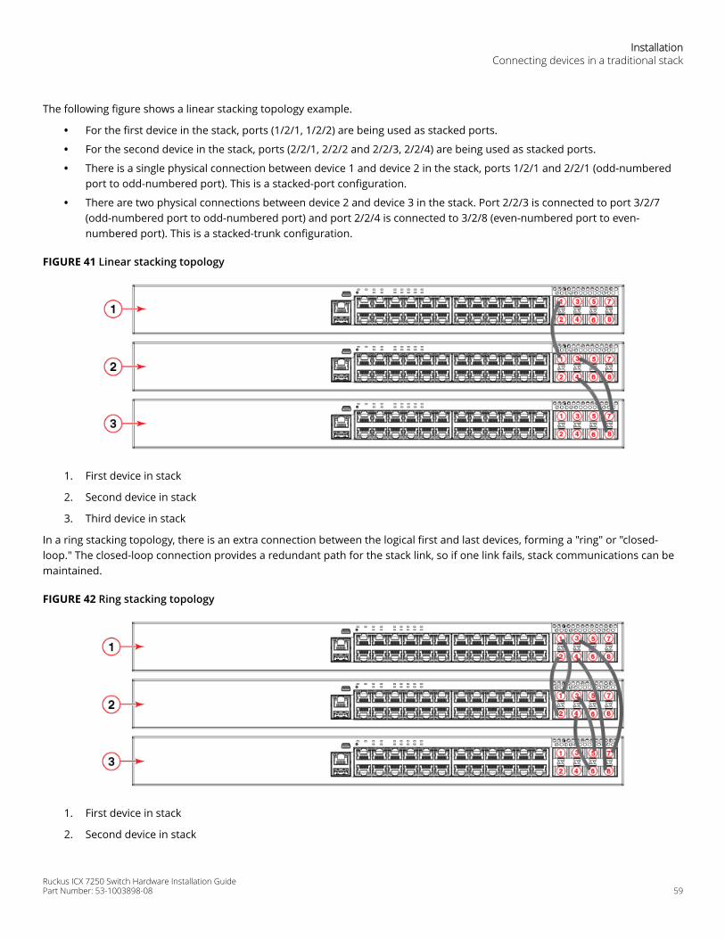
The following figure shows a linear stacking topology example.
• For the first device in the stack, ports (1/2/1, 1/2/2) are being used as stacked ports.
• For the second device in the stack, ports (2/2/1, 2/2/2 and 2/2/3, 2/2/4) are being used as stacked ports.
• There is a single physical connection between device 1 and device 2 in the stack, ports 1/2/1 and 2/2/1 (odd-numberedport to odd-numbered port). This is a stacked-port configuration.
• There are two physical connections between device 2 and device 3 in the stack. Port 2/2/3 is connected to port 3/2/7(odd-numbered port to odd-numbered port) and port 2/2/4 is connected to 3/2/8 (even-numbered port to even-numbered port). This is a stacked-trunk configuration.
FIGURE 41 Linear stacking topology
1. First device in stack
2. Second device in stack
3. Third device in stack
In a ring stacking topology, there is an extra connection between the logical first and last devices, forming a "ring" or "closed-loop." The closed-loop connection provides a redundant path for the stack link, so if one link fails, stack communications can bemaintained.
FIGURE 42 Ring stacking topology
1. First device in stack
2. Second device in stack
InstallationConnecting devices in a traditional stack
Ruckus ICX 7250 Switch Hardware Installation GuidePart Number: 53-1003898-08 59
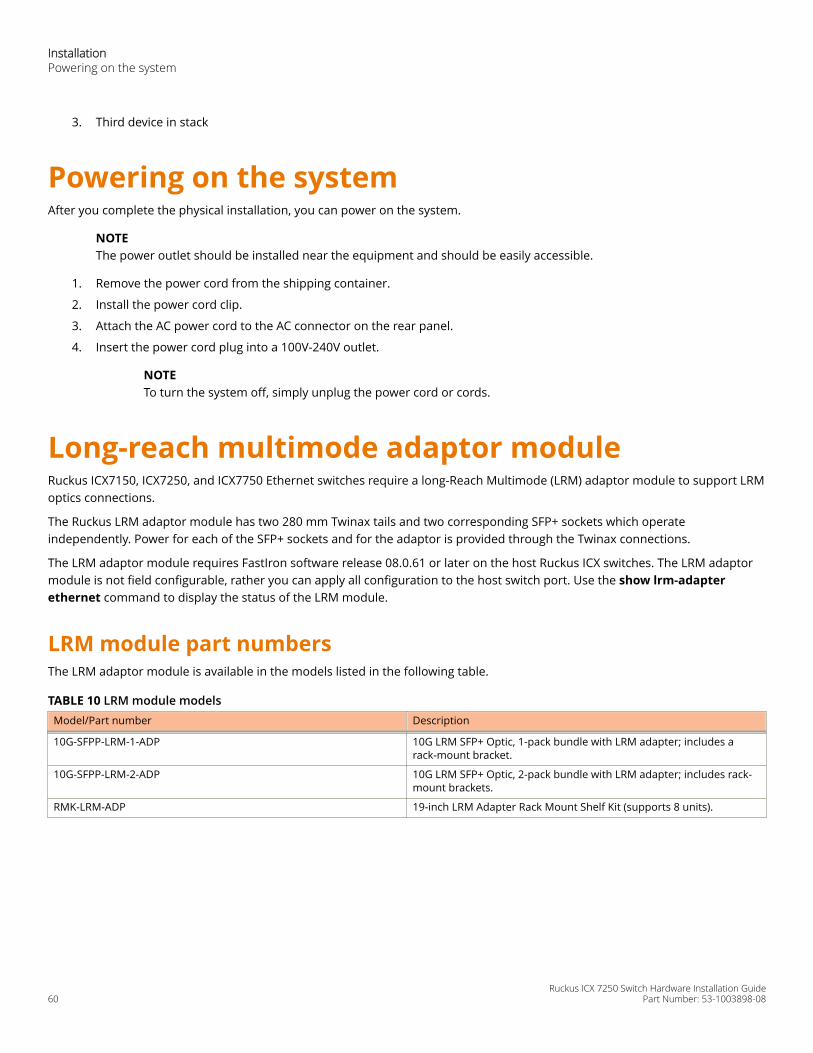
3. Third device in stack
Powering on the systemAfter you complete the physical installation, you can power on the system.
NOTEThe power outlet should be installed near the equipment and should be easily accessible.
1. Remove the power cord from the shipping container.
2. Install the power cord clip.
3. Attach the AC power cord to the AC connector on the rear panel.
4. Insert the power cord plug into a 100V-240V outlet.
NOTETo turn the system off, simply unplug the power cord or cords.
Long-reach multimode adaptor moduleRuckus ICX7150, ICX7250, and ICX7750 Ethernet switches require a long-Reach Multimode (LRM) adaptor module to support LRMoptics connections.
The Ruckus LRM adaptor module has two 280 mm Twinax tails and two corresponding SFP+ sockets which operateindependently. Power for each of the SFP+ sockets and for the adaptor is provided through the Twinax connections.
The LRM adaptor module requires FastIron software release 08.0.61 or later on the host Ruckus ICX switches. The LRM adaptormodule is not field configurable, rather you can apply all configuration to the host switch port. Use the show lrm-adapterethernet command to display the status of the LRM module.
LRM module part numbersThe LRM adaptor module is available in the models listed in the following table.
TABLE 10 LRM module modelsModel/Part number Description
10G-SFPP-LRM-1-ADP 10G LRM SFP+ Optic, 1-pack bundle with LRM adapter; includes arack-mount bracket.
10G-SFPP-LRM-2-ADP 10G LRM SFP+ Optic, 2-pack bundle with LRM adapter; includes rack-mount brackets.
RMK-LRM-ADP 19-inch LRM Adapter Rack Mount Shelf Kit (supports 8 units).
InstallationPowering on the system
Ruckus ICX 7250 Switch Hardware Installation Guide60 Part Number: 53-1003898-08
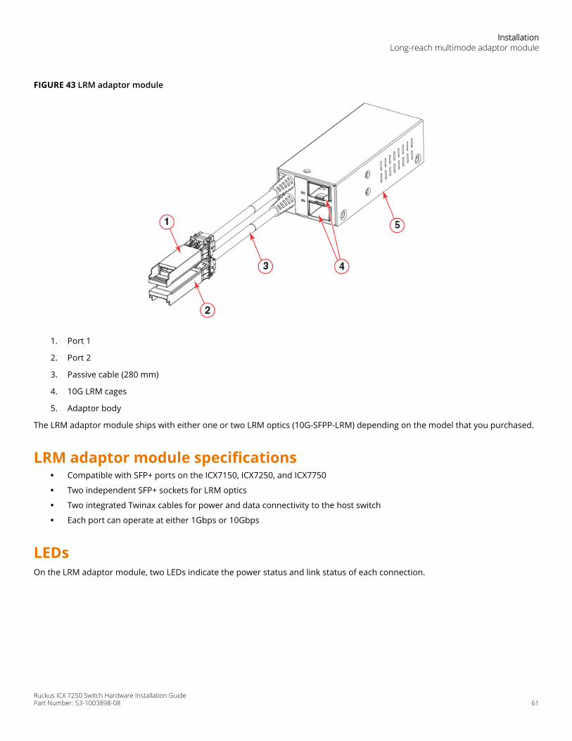
FIGURE 43 LRM adaptor module
1. Port 1
2. Port 2
3. Passive cable (280 mm)
4. 10G LRM cages
5. Adaptor body
The LRM adaptor module ships with either one or two LRM optics (10G-SFPP-LRM) depending on the model that you purchased.
LRM adaptor module specifications• Compatible with SFP+ ports on the ICX7150, ICX7250, and ICX7750
• Two independent SFP+ sockets for LRM optics
• Two integrated Twinax cables for power and data connectivity to the host switch
• Each port can operate at either 1Gbps or 10Gbps
LEDsOn the LRM adaptor module, two LEDs indicate the power status and link status of each connection.
InstallationLong-reach multimode adaptor module
Ruckus ICX 7250 Switch Hardware Installation GuidePart Number: 53-1003898-08 61
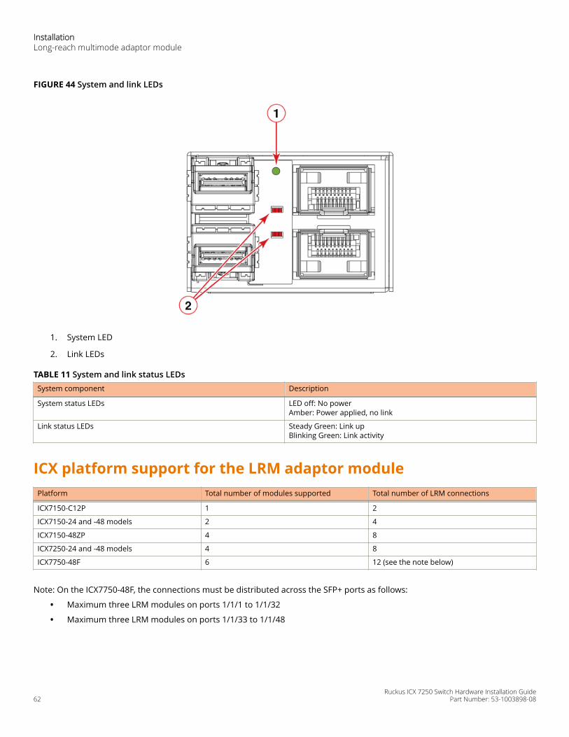
FIGURE 44 System and link LEDs
1. System LED
2. Link LEDs
TABLE 11 System and link status LEDsSystem component Description
System status LEDs LED off: No powerAmber: Power applied, no link
Link status LEDs Steady Green: Link upBlinking Green: Link activity
ICX platform support for the LRM adaptor modulePlatform Total number of modules supported Total number of LRM connections
ICX7150-C12P 1 2
ICX7150-24 and -48 models 2 4
ICX7150-48ZP 4 8
ICX7250-24 and -48 models 4 8
ICX7750-48F 6 12 (see the note below)
Note: On the ICX7750-48F, the connections must be distributed across the SFP+ ports as follows:
• Maximum three LRM modules on ports 1/1/1 to 1/1/32
• Maximum three LRM modules on ports 1/1/33 to 1/1/48
InstallationLong-reach multimode adaptor module
Ruckus ICX 7250 Switch Hardware Installation Guide62 Part Number: 53-1003898-08
Unpacking the LRM adaptor moduleWhen unpacking the LRM adaptor module, verify that the shipping carton has the items as listed below. Save the shipping cartonand packaging incase you need to return the shipment.
• One LRM adaptor module
• One or two L-shaped mounting bracket (depending on the model purchased)
• One or two 10G-SFPP-LRM optics (depending on the model purchased)
• China-RoHS Hazardous and Toxic Substance statement
InstallationLong-reach multimode adaptor module
Ruckus ICX 7250 Switch Hardware Installation GuidePart Number: 53-1003898-08 63

Ruckus ICX 7250 Switch Hardware Installation Guide64 Part Number: 53-1003898-08

Installing the EPS4000• EPS4000 external power supply................................................................................................................................ 65• Items included with the EPS4000.............................................................................................................................. 69• Configuration requirements...................................................................................................................................... 69• Summary of installation tasks................................................................................................................................... 69• Installation precautions.............................................................................................................................................. 70• Preparing the installation site....................................................................................................................................71• Installing the device.....................................................................................................................................................71• Installing an RPS17 PSU.............................................................................................................................................. 74• Uninstalling an RPS17 PSU......................................................................................................................................... 75• Connecting the EPS4000 cord....................................................................................................................................76• Powering on the system............................................................................................................................................. 78• Verifying proper operation.........................................................................................................................................79• EPS4000 external power supply technical specifications....................................................................................... 79
DANGERThe procedures in this manual are for qualified service personnel.
DANGERBefore beginning the installation, see the precautions in “Power precautions.”
DANGERBe careful not to accidently insert your fingers into the fan tray while removing it from the chassis. The fan may stillbe spinning at a high speed.
EPS4000 external power supplyIn the event of an AC power loss or internal power supply device failure, the Ruckus EPS4000 external power supply can be usedas a 12 V, backup power source to a device when any of the DC power supply ports are connected to an ICX 7250 device. TheEPS4000 requires a minimum of one RPS17 Power Supply Unit (PSU) to be functional. Proprietary DC cables are used to connectany of the EPS DC ports of the EPS4000 to the rear EPS4000 port of an ICX 7250 device that is supported by the EPS4000. EachRPS17 PSU can provide backup power to one ICX 7250 device. Even though a fully populated EPS4000 can monitor up to sixteenconnected devices, the EPS4000 can provide backup power without performance degradation to only four ICX 7250 devices.
NOTEThe primary source of 12 V power for an ICX 7250 device is the internal power supply. The EPS4000 is designed to serveprimarily as a backup source of 12 V power. You should service a failed ICX 7250 device as soon as possible after a 12 Vpower failure is detected.
In case of a 54 V supply failure, the EPS4000 can provide power to multiple devices up to its capacity limit. You can set the systempriority for the power budget allocation for this scenario. The default is for the lower-numbered port to have the higher priority.Should a higher priority device have a 54 V supply failure while a lower priority device is already being serviced by the PSU, thepower supply will not switch to provide power to the higher priority device to maintain continuity of service. The EPS4000 usesthe next PoE-power-budget cycle to reallocate power among the connected ICX 7250 devices.
Ruckus ICX 7250 Switch Hardware Installation GuidePart Number: 53-1003898-08 65

In the PoE power extension mode, the EPS4000 can also provide additional power to support the PoE ports as needed. For moreinformation about connecting an ICX 7250 device to the EPS4000, refer to Connecting devices to the external power supply onpage 79.
Each RPS17 PSU can provide up to 740 W at 54 V and 120 W at 12 V. The RPS17 draws power from a standard AC source andconverts it to DC for use by the switches.
NOTEThe internal power supply of the ICX 7250 devices is not a field-replaceable unit (FRU). The devices must be shut downby administrators for replacement.
Ruckus recommends that you pay attention to the PoE or PoE+ port configuration of the device when connecting to an EPS4000.The internal power supply of each PoE or PoE+ device has a maximum number of supported PoE or PoE+ ports. Ruckusrecommends that when the EPS4000 is used as a redundant power source for the PoE device, that the maximum number of PoEor PoE+ ports of the external power supply must not exceed the maximum number of PoE or PoE+ ports of the internal powersupply capability of each device.
The following devices are supported by the Ruckus EPS4000:
• ICX 7250-24
• ICX 7250-24P
• ICX 7250-48
• ICX 7250-48P
NOTEThe ICX 7250-24G is not supported by the EPS4000.
EPS4000 features and benefits• Hosts up to four hot-swappable RPS17 power supply units (PSUs).
• Provides N:1 power redundancy at 12 V with each PSU.
• Each RPS17 can deliver a maximum of 740 W at 54 V and 120 W at 12 V.
• A fully populated EPS4000 has 8 DC power ports that can monitor up to 16 switches simultaneously and provide 12 Vredundant power to four switches.
• Provides power redundancy at 54 V and true extended PoE power support.
• 1:1 and 1:2 cables support 54 V or 12 V distribution up to 1 meter.
• Universal (100-240 V) AC line cord draws power from standard power outlet.
• The EPS4000 firmware is field-upgradeable.
• The power to the switches is maintained while the microcontroller unit (MCU) is being reset.
• The power distribution to the connected switches can be controlled per a priority scheme that you set.
EPS4000 front and rear panelsThere are 32 LEDs on the front panel of the EPS4000 to indicate the status for the DC power on the 8 ports. 16 LEDs (Ex.y) are forthe 54 VDC and the other sixteen (Rx.y) are for the 12 VDC supply. There is a reset button next to the LEDs. There are port LEDsfor each of the management ports. Both the serial port and the out-of-band Ethernet management ports use RJ-45 connectors.The slots for the RPS17 PSUs are covered with slot covers. The slot cover must be removed to install the PSU.
Installing the EPS4000 EPS4000 external power supply
Ruckus ICX 7250 Switch Hardware Installation Guide66 Part Number: 53-1003898-08
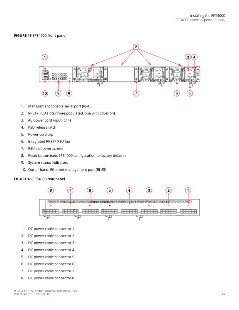
FIGURE 45 EPS4000 front panel
1. Management console serial port (RJ-45)
2. RPS17 PSU slots (three populated, one with cover on)
3. AC power cord input (C14)
4. PSU release latch
5. Power cord clip
6. Integrated RPS17 PSU fan
7. PSU slot cover screws
8. Reset button (sets EPS4000 configuration to factory default)
9. System status indicators
10. Out-of-band, Ethernet management port (RJ-45)
FIGURE 46 EPS4000 rear panel
1. DC power cable connector 1
2. DC power cable connector 2
3. DC power cable connector 3
4. DC power cable connector 4
5. DC power cable connector 5
6. DC power cable connector 6
7. DC power cable connector 7
8. DC power cable connector 8
Installing the EPS4000EPS4000 external power supply
Ruckus ICX 7250 Switch Hardware Installation GuidePart Number: 53-1003898-08 67
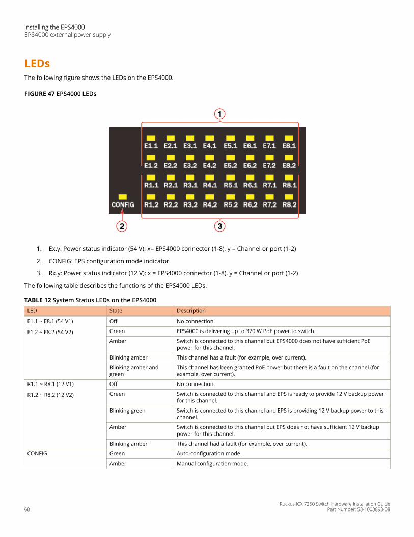
LEDsThe following figure shows the LEDs on the EPS4000.
FIGURE 47 EPS4000 LEDs
1. Ex.y: Power status indicator (54 V): x= EPS4000 connector (1-8), y = Channel or port (1-2)
2. CONFIG: EPS configuration mode indicator
3. Rx.y: Power status indicator (12 V): x = EPS4000 connector (1-8), y = Channel or port (1-2)
The following table describes the functions of the EPS4000 LEDs.
TABLE 12 System Status LEDs on the EPS4000LED State Description
E1.1 ~ E8.1 (54 V1)
E1.2 ~ E8.2 (54 V2)
Off No connection.
Green EPS4000 is delivering up to 370 W PoE power to switch.
Amber Switch is connected to this channel but EPS4000 does not have sufficient PoEpower for this channel.
Blinking amber This channel has a fault (for example, over current).
Blinking amber andgreen
This channel has been granted PoE power but there is a fault on the channel (forexample, over current).
R1.1 ~ R8.1 (12 V1)
R1.2 ~ R8.2 (12 V2)
Off No connection.
Green Switch is connected to this channel and EPS is ready to provide 12 V backup powerfor this channel.
Blinking green Switch is connected to this channel and EPS is providing 12 V backup power to thischannel.
Amber Switch is connected to this channel but EPS does not have sufficient 12 V backuppower for this channel.
Blinking amber This channel had a fault (for example, over current).
CONFIG Green Auto-configuration mode.
Amber Manual configuration mode.
Installing the EPS4000 EPS4000 external power supply
Ruckus ICX 7250 Switch Hardware Installation Guide68 Part Number: 53-1003898-08
TABLE 12 System Status LEDs on the EPS4000 (continued)LED State Description
Management port LED
(Left down)
Green Management port link up at 100BASE-T mode.
Off Management port link up at 10BASE-T mode or link is down.
Management port LED
(Right down)
Blinking green Indicates management port receive and transmit activity.
Off Indicates no Ethernet traffic on management port.
Items included with the EPS4000The EPS4000 ships with all of the following items included in your shipping container. Verify the contents of your shippingcontainer. If any items are missing, contact the place of purchase.
• EPS4000 external power supply
• Rack mounting kit containing two L-shaped mounting brackets and eight sink-head screws
• Two-post rack kit containing four rack-mounting screws and four cage nuts
• Four rubber feet
• Console cable
• RJ-45 to DB9 adapter
• China ROHS sheet
• Read Me First document
Configuration requirementsThe configuration requirements for the EPS4000 are the same as the for the ICX 7250. Refer to Configuration requirements onpage 23.
Summary of installation tasksFollow the steps in the following table to install your device. Details for each of these steps are provided on the pages indicated.
TABLE 13 Installation tasks Task number Task Where to find more information
1 Ensure that the physical environment that willhost the device has the proper cabling andventilation.
Preparing the installation site on page 71section
2 Unpack the device and all includedaccessories.
Items included with the EPS4000 on page 69section
3 Install the device on a desktop, or in anequipment rack.
Installing the device on page 71 section
4 Once the device is installed, plug the deviceinto a nearby power source that adheres tothe regulatory requirements outlined in thismanual.
Powering on the system on page 78 section
Installing the EPS4000Summary of installation tasks
Ruckus ICX 7250 Switch Hardware Installation GuidePart Number: 53-1003898-08 69
TABLE 13 Installation tasks (continued)Task number Task Where to find more information
5 Verify that the device is working properly byplugging it into a power source and verifyingthat it passes the self test.
Verifying proper operation on page 79section
Installation precautionsFollow all precautions when installing a device.
General precautionsDANGERAll fiber-optic interfaces use Class 1 lasers.
CAUTIONDo not install the device in an environment where the operating ambient temperature might exceed 50°C(122°F).
CAUTIONMake sure the airflow around the front, and back of the device is not restricted.
Lifting precautionsDANGERMake sure the rack housing the device is adequately secured to prevent it from becoming unstable or falling over.
DANGERMount the devices you install in a rack as low as possible. Place the heaviest device at the bottom and progressivelyplace lighter devices above.
Power precautionsCAUTIONUse a separate branch circuit for each power cord, which provides redundancy in case one of the circuits fails.
CAUTIONEnsure that the device does not overload the power circuits, wiring, and over-current protection. To determinethe possibility of overloading the supply circuits, add the ampere (amp) ratings of all devices installed on thesame circuit as the device. Compare this total with the rating limit for the circuit. The maximum ampere ratingsare usually printed on the devices near the input power connectors.
DANGERDisconnect the power cord from all power sources to completely remove power from the device.
Installing the EPS4000 Installation precautions
Ruckus ICX 7250 Switch Hardware Installation Guide70 Part Number: 53-1003898-08
CAUTIONBefore plugging a cable into any port, be sure to discharge the voltage stored on the cable by touching theelectrical contacts to ground surface.
DANGERIf the installation requires a different power cord than the one supplied with the device, make sure you use a powercord displaying the mark of the safety agency that defines the regulations for power cords in your country. The markis your assurance that the power cord can be used safely with the device.
Preparing the installation siteEPS4000 external power supplies can be mounted in a standard 19-inch equipment rack or on a flat surface.
The installation site should meet these requirements:
• Be at the center of all the devices you want to link, and near a power outlet.
• Maintain temperatures within 0 to 50°C (32 to 122°F) and humidity levels within 5 to 95%, non-condensing.
• Provide adequate space (approximately 5.08 cm [2 in.]) on all sides for proper airflow.
• Be accessible for installing, cabling, and maintaining the devices.
• Allow the status LEDs to be clearly visible.
• Allow for twisted-pair cables to be routed away from power lines, fluorescent lighting fixtures, and other sources ofelectrical interference, such as radios and transmitters.
• Provide a separate grounded power outlet that provides 100 to 240 VAC, 50 - 60 Hz, is within 2.44 m (8 ft) of each device,and is powered from an independent circuit breaker.
• As with any electrical equipment, a filter or surge suppressor is recommended.
Rack-mount installation considerationsBefore mounting the external power supply in a rack, consider the following factors:
• Temperature: Because the temperature within a rack assembly may be higher than the ambient room temperature,check that the rack-environment temperature is within the specified operating temperature range.
• Airflow: Be sure that the airflow direction for all equipment in a rack is the same or consistent.
• Mechanical loading: Do not place any equipment on top of a rack-mounted device.
• Circuit overloading: Be sure that the supply circuit to the rack assembly is not overloaded.
• Grounding: Rack-mounted equipment should be properly grounded.
Installing the deviceYou can install the device on a desktop or in an equipment rack.
DANGERMount the devices you install in a rack as low as possible. Place the heaviest device at the bottom and progressivelyplace lighter devices above.
Installing the EPS4000Installing the device
Ruckus ICX 7250 Switch Hardware Installation GuidePart Number: 53-1003898-08 71
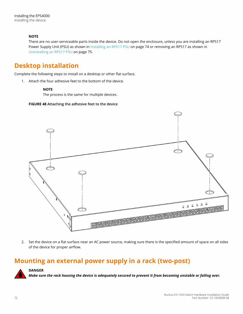
NOTEThere are no user-serviceable parts inside the device. Do not open the enclosure, unless you are installing an RPS17Power Supply Unit (PSU) as shown in Installing an RPS17 PSU on page 74 or removing an RPS17 as shown in Uninstalling an RPS17 PSU on page 75.
Desktop installationComplete the following steps to install on a desktop or other flat surface.
1. Attach the four adhesive feet to the bottom of the device.
NOTEThe process is the same for multiple devices.
FIGURE 48 Attaching the adhesive feet to the device
2. Set the device on a flat surface near an AC power source, making sure there is the specified amount of space on all sidesof the device for proper airflow.
Mounting an external power supply in a rack (two-post)DANGERMake sure the rack housing the device is adequately secured to prevent it from becoming unstable or falling over.
Installing the EPS4000 Installing the device
Ruckus ICX 7250 Switch Hardware Installation Guide72 Part Number: 53-1003898-08
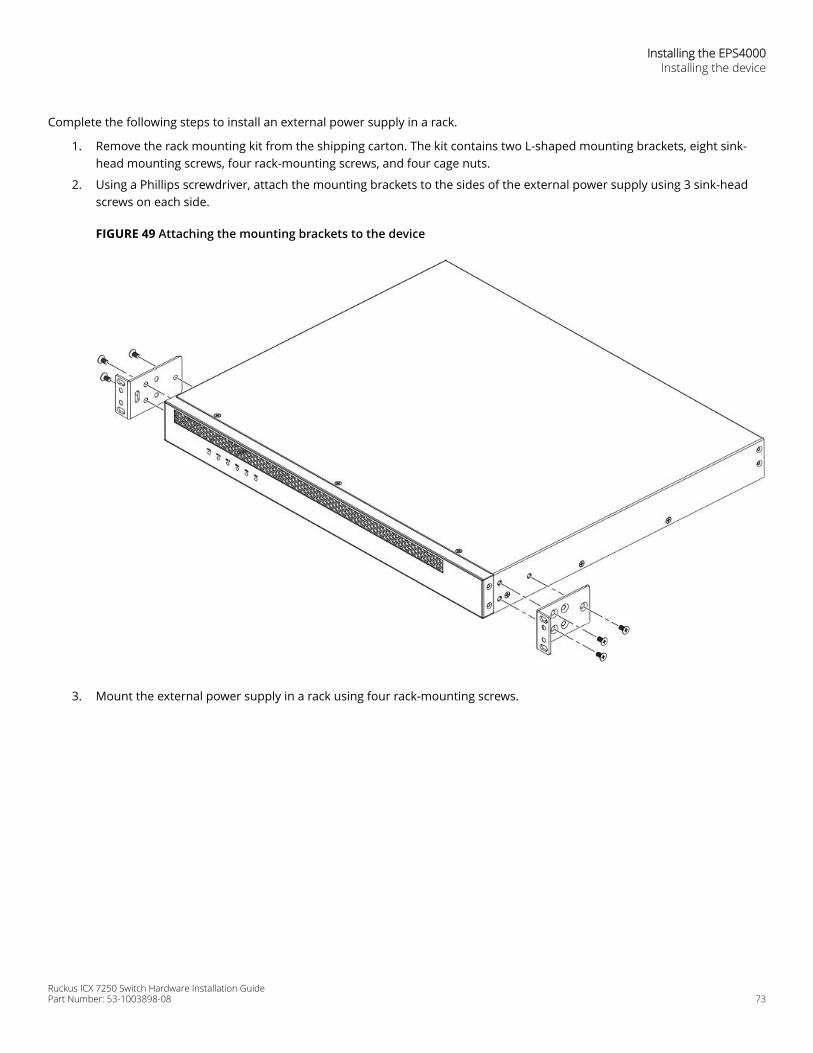
Complete the following steps to install an external power supply in a rack.
1. Remove the rack mounting kit from the shipping carton. The kit contains two L-shaped mounting brackets, eight sink-head mounting screws, four rack-mounting screws, and four cage nuts.
2. Using a Phillips screwdriver, attach the mounting brackets to the sides of the external power supply using 3 sink-headscrews on each side.
FIGURE 49 Attaching the mounting brackets to the device
3. Mount the external power supply in a rack using four rack-mounting screws.
Installing the EPS4000Installing the device
Ruckus ICX 7250 Switch Hardware Installation GuidePart Number: 53-1003898-08 73
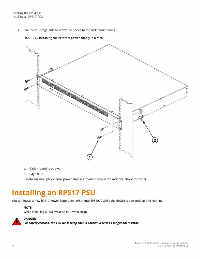
4. Use the four cage nuts to screw the device to the rack mount holes.
FIGURE 50 Installing the external power supply in a rack
a. Rack-mounting screws
b. Cage nuts
5. If installing multiple external power supplies, mount them in the rack one above the other.
Installing an RPS17 PSUYou can install a new RPS17 Power Supply Unit (PSU) into EPS4000 while the device is powered on and running.
NOTEWhile installing a PSU, wear an ESD wrist strap.
DANGERFor safety reasons, the ESD wrist strap should contain a series 1 megaohm resistor.
Installing the EPS4000 Installing an RPS17 PSU
Ruckus ICX 7250 Switch Hardware Installation Guide74 Part Number: 53-1003898-08
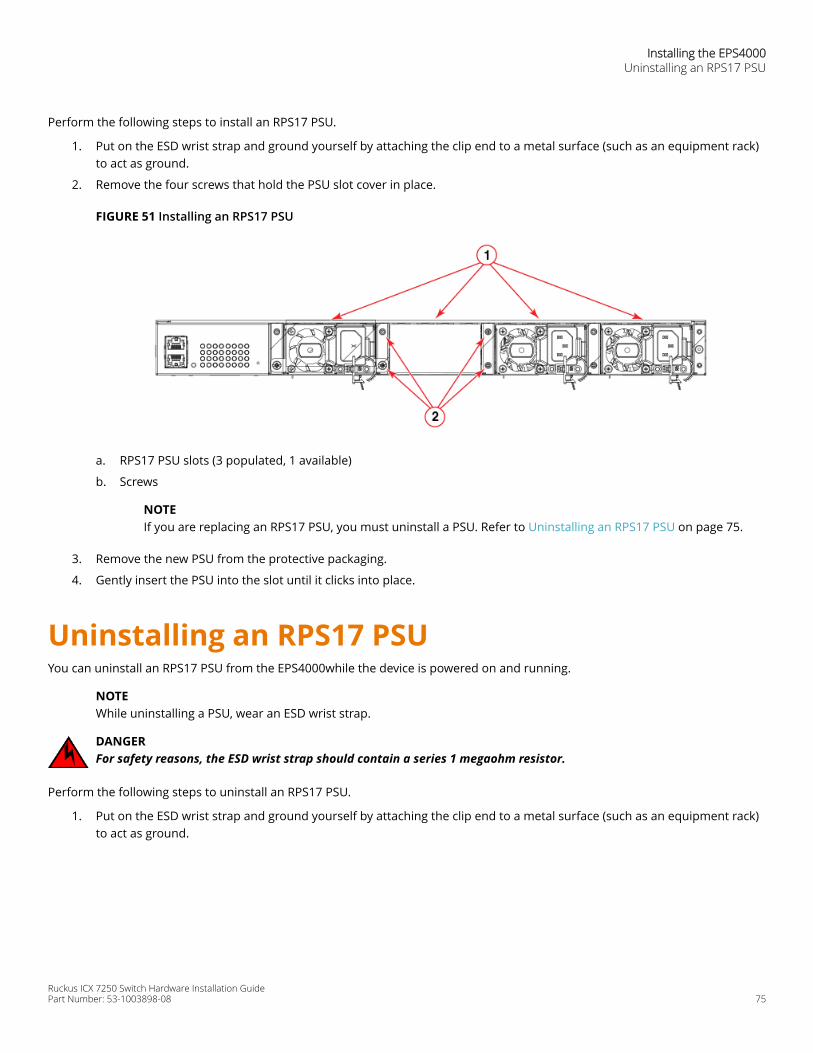
Perform the following steps to install an RPS17 PSU.
1. Put on the ESD wrist strap and ground yourself by attaching the clip end to a metal surface (such as an equipment rack)to act as ground.
2. Remove the four screws that hold the PSU slot cover in place.
FIGURE 51 Installing an RPS17 PSU
a. RPS17 PSU slots (3 populated, 1 available)
b. Screws
NOTEIf you are replacing an RPS17 PSU, you must uninstall a PSU. Refer to Uninstalling an RPS17 PSU on page 75.
3. Remove the new PSU from the protective packaging.
4. Gently insert the PSU into the slot until it clicks into place.
Uninstalling an RPS17 PSUYou can uninstall an RPS17 PSU from the EPS4000while the device is powered on and running.
NOTEWhile uninstalling a PSU, wear an ESD wrist strap.
DANGERFor safety reasons, the ESD wrist strap should contain a series 1 megaohm resistor.
Perform the following steps to uninstall an RPS17 PSU.
1. Put on the ESD wrist strap and ground yourself by attaching the clip end to a metal surface (such as an equipment rack)to act as ground.
Installing the EPS4000Uninstalling an RPS17 PSU
Ruckus ICX 7250 Switch Hardware Installation GuidePart Number: 53-1003898-08 75
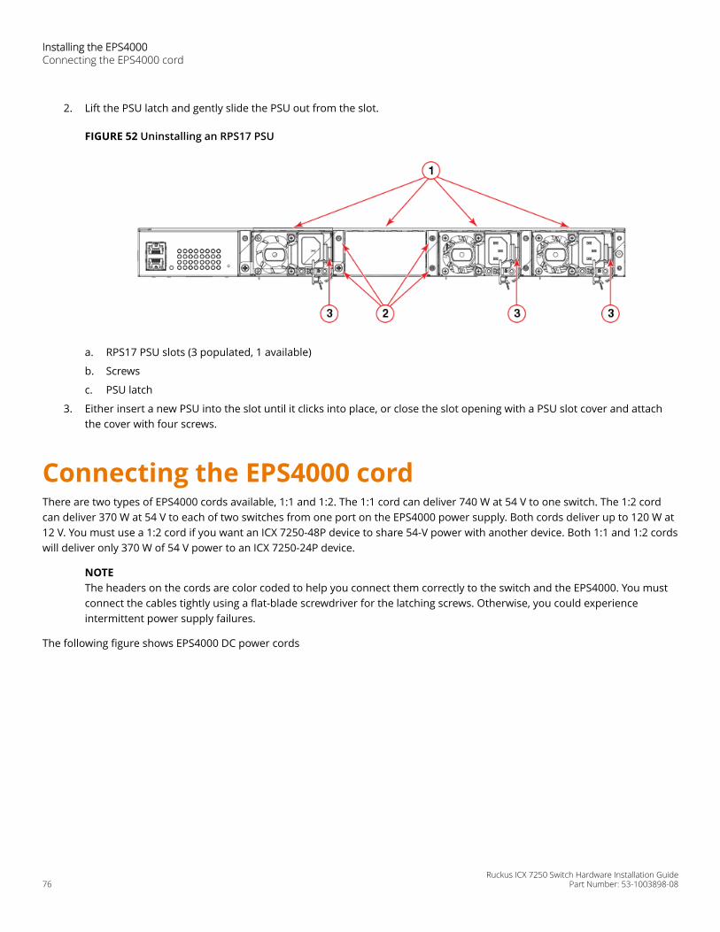
2. Lift the PSU latch and gently slide the PSU out from the slot.
FIGURE 52 Uninstalling an RPS17 PSU
a. RPS17 PSU slots (3 populated, 1 available)
b. Screws
c. PSU latch
3. Either insert a new PSU into the slot until it clicks into place, or close the slot opening with a PSU slot cover and attachthe cover with four screws.
Connecting the EPS4000 cordThere are two types of EPS4000 cords available, 1:1 and 1:2. The 1:1 cord can deliver 740 W at 54 V to one switch. The 1:2 cordcan deliver 370 W at 54 V to each of two switches from one port on the EPS4000 power supply. Both cords deliver up to 120 W at12 V. You must use a 1:2 cord if you want an ICX 7250-48P device to share 54-V power with another device. Both 1:1 and 1:2 cordswill deliver only 370 W of 54 V power to an ICX 7250-24P device.
NOTEThe headers on the cords are color coded to help you connect them correctly to the switch and the EPS4000. You mustconnect the cables tightly using a flat-blade screwdriver for the latching screws. Otherwise, you could experienceintermittent power supply failures.
The following figure shows EPS4000 DC power cords
Installing the EPS4000 Connecting the EPS4000 cord
Ruckus ICX 7250 Switch Hardware Installation Guide76 Part Number: 53-1003898-08
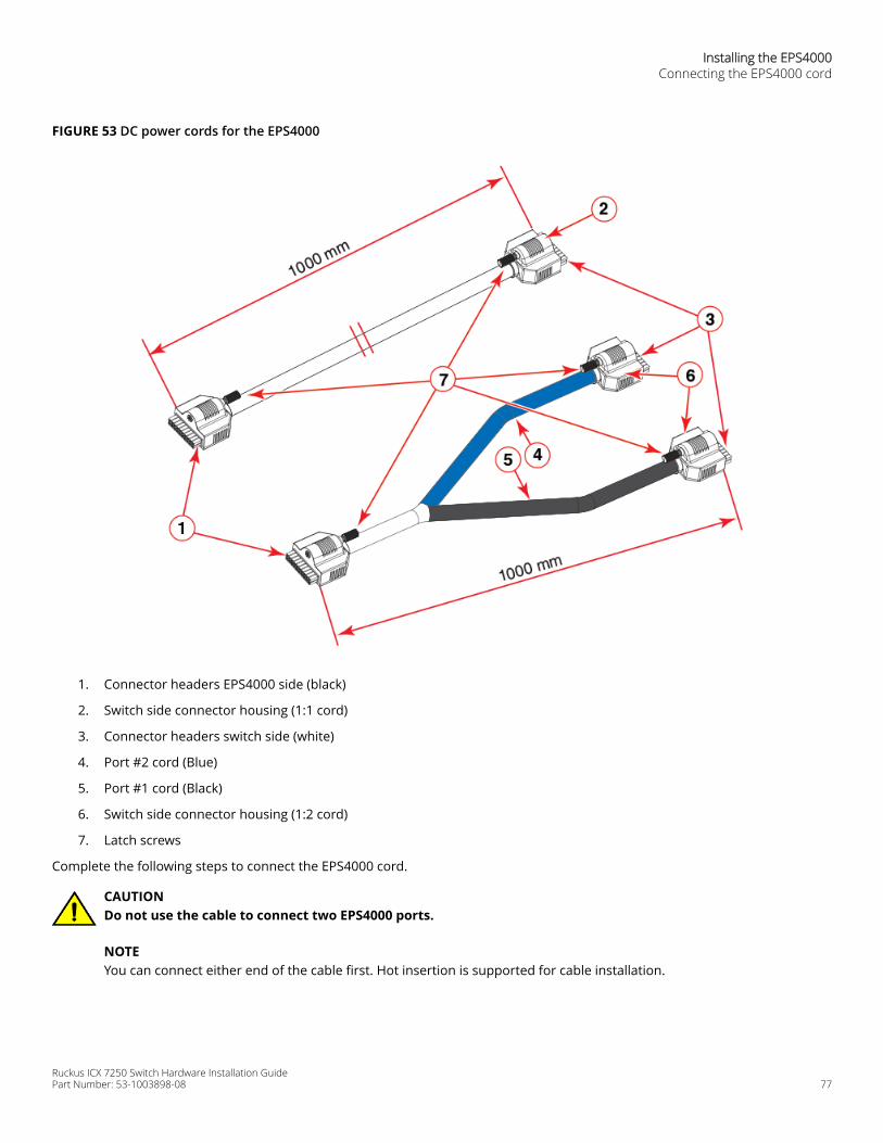
FIGURE 53 DC power cords for the EPS4000
1. Connector headers EPS4000 side (black)
2. Switch side connector housing (1:1 cord)
3. Connector headers switch side (white)
4. Port #2 cord (Blue)
5. Port #1 cord (Black)
6. Switch side connector housing (1:2 cord)
7. Latch screws
Complete the following steps to connect the EPS4000 cord.
CAUTIONDo not use the cable to connect two EPS4000 ports.
NOTEYou can connect either end of the cable first. Hot insertion is supported for cable installation.
Installing the EPS4000Connecting the EPS4000 cord
Ruckus ICX 7250 Switch Hardware Installation GuidePart Number: 53-1003898-08 77
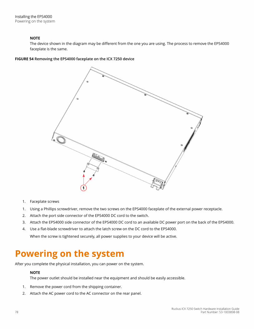
NOTEThe device shown in the diagram may be different from the one you are using. The process to remove the EPS4000faceplate is the same.
FIGURE 54 Removing the EPS4000 faceplate on the ICX 7250 device
1. Faceplate screws
1. Using a Phillips screwdriver, remove the two screws on the EPS4000 faceplate of the external power receptacle.
2. Attach the port side connector of the EPS4000 DC cord to the switch.
3. Attach the EPS4000 side connector of the EPS4000 DC cord to an available DC power port on the back of the EPS4000.
4. Use a flat-blade screwdriver to attach the latch screw on the DC cord to the EPS4000.
When the screw is tightened securely, all power supplies to your device will be active.
Powering on the systemAfter you complete the physical installation, you can power on the system.
NOTEThe power outlet should be installed near the equipment and should be easily accessible.
1. Remove the power cord from the shipping container.
2. Attach the AC power cord to the AC connector on the rear panel.
Installing the EPS4000 Powering on the system
Ruckus ICX 7250 Switch Hardware Installation Guide78 Part Number: 53-1003898-08

3. Insert the power cord plug into a 100V-240V outlet.
NOTETo turn the system off, unplug the power cord or cords.
Connecting devices to the external power supplyComplete the following steps to connect devices to the external power supply.
1. Connect one end of the AC cord to the AC receptacle on the device, and the other end to a grounded power outlet.
2. Connect one end of an EPS cord to the external power receptacle on the device, and the other end to an availablereceptacle on the external power supply.
3. Repeat Step Step 1and Step Step 2to connect up to the allowable maximum number of devices to the external powersupply. The maximum number of devices will depend on both the number of power supply units in the EPS4000 andwhether you use 1:1 cords or 1:2 cords.
4. Connect one end of the AC cord to the AC receptacle on the external power supply, and the other end to a groundedpower outlet.
5. Check the LEDs on the external power supply to ensure proper operation with the devices.
Verifying proper operationAfter you have installed an external power supply, verify that the device is working properly by plugging it into a power sourceand verifying that it passes the self test.
1. Connect the power cord supplied with the device to the power connector on the power supply on the rear of the device.
2. Insert the other end into a properly grounded electrical outlet.
3. Verify that the LED for the power supply is green.
4. Verify proper operation by observing the LEDs.
LEDs for linked ports will come on during the boot process, and then all LEDs will go off. Once the boot sequence iscomplete, LEDs for linked ports will come on again.
EPS4000 external power supply technicalspecifications
System specificationsSystem component Description
Enclosure 1U; 19-inch rack-mountable or desktop
Power inlet C14 for AC power
Power outlet Custom connector for DC power to all ICX 7250 devices except ICX 7250-24G
Power supply unit (PSU) Up to four RPS17, field-replaceable units (FRU)
Fans One fan per installed RPS17
Installing the EPS4000 EPS4000 external power supply technical specifications
Ruckus ICX 7250 Switch Hardware Installation GuidePart Number: 53-1003898-08 79
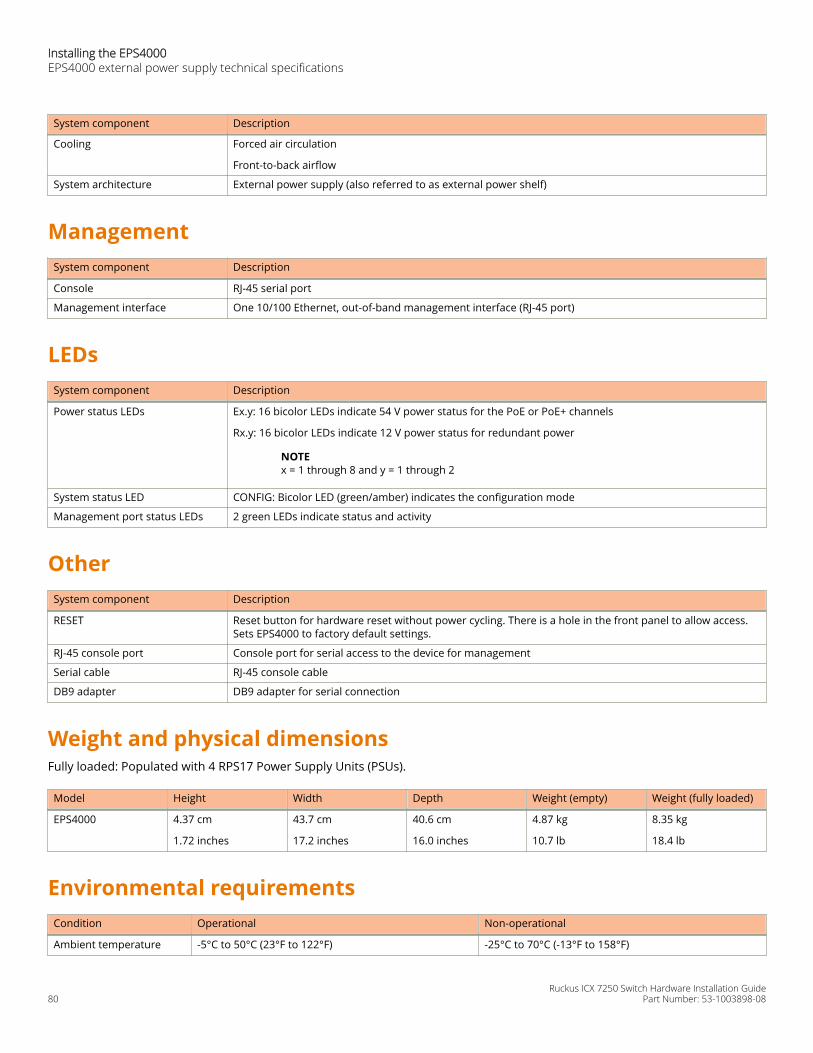
System component Description
Cooling Forced air circulation
Front-to-back airflow
System architecture External power supply (also referred to as external power shelf)
ManagementSystem component Description
Console RJ-45 serial port
Management interface One 10/100 Ethernet, out-of-band management interface (RJ-45 port)
LEDsSystem component Description
Power status LEDs Ex.y: 16 bicolor LEDs indicate 54 V power status for the PoE or PoE+ channels
Rx.y: 16 bicolor LEDs indicate 12 V power status for redundant power
NOTEx = 1 through 8 and y = 1 through 2
System status LED CONFIG: Bicolor LED (green/amber) indicates the configuration mode
Management port status LEDs 2 green LEDs indicate status and activity
OtherSystem component Description
RESET Reset button for hardware reset without power cycling. There is a hole in the front panel to allow access.Sets EPS4000 to factory default settings.
RJ-45 console port Console port for serial access to the device for management
Serial cable RJ-45 console cable
DB9 adapter DB9 adapter for serial connection
Weight and physical dimensionsFully loaded: Populated with 4 RPS17 Power Supply Units (PSUs).
Model Height Width Depth Weight (empty) Weight (fully loaded)
EPS4000 4.37 cm
1.72 inches
43.7 cm
17.2 inches
40.6 cm
16.0 inches
4.87 kg
10.7 lb
8.35 kg
18.4 lb
Environmental requirementsCondition Operational Non-operational
Ambient temperature -5°C to 50°C (23°F to 122°F) -25°C to 70°C (-13°F to 158°F)
Installing the EPS4000 EPS4000 external power supply technical specifications
Ruckus ICX 7250 Switch Hardware Installation Guide80 Part Number: 53-1003898-08
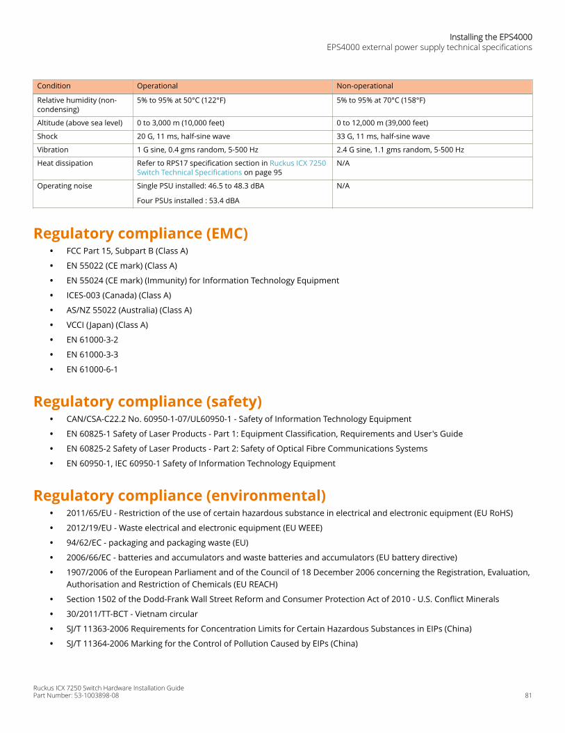
Condition Operational Non-operational
Relative humidity (non-condensing)
5% to 95% at 50°C (122°F) 5% to 95% at 70°C (158°F)
Altitude (above sea level) 0 to 3,000 m (10,000 feet) 0 to 12,000 m (39,000 feet)
Shock 20 G, 11 ms, half-sine wave 33 G, 11 ms, half-sine wave
Vibration 1 G sine, 0.4 gms random, 5-500 Hz 2.4 G sine, 1.1 gms random, 5-500 Hz
Heat dissipation Refer to RPS17 specification section in Ruckus ICX 7250Switch Technical Specifications on page 95
N/A
Operating noise Single PSU installed: 46.5 to 48.3 dBA
Four PSUs installed : 53.4 dBA
N/A
Regulatory compliance (EMC)• FCC Part 15, Subpart B (Class A)
• EN 55022 (CE mark) (Class A)
• EN 55024 (CE mark) (Immunity) for Information Technology Equipment
• ICES-003 (Canada) (Class A)
• AS/NZ 55022 (Australia) (Class A)
• VCCI ( Japan) (Class A)
• EN 61000-3-2
• EN 61000-3-3
• EN 61000-6-1
Regulatory compliance (safety)• CAN/CSA-C22.2 No. 60950-1-07/UL60950-1 - Safety of Information Technology Equipment
• EN 60825-1 Safety of Laser Products - Part 1: Equipment Classification, Requirements and User's Guide
• EN 60825-2 Safety of Laser Products - Part 2: Safety of Optical Fibre Communications Systems
• EN 60950-1, IEC 60950-1 Safety of Information Technology Equipment
Regulatory compliance (environmental)• 2011/65/EU - Restriction of the use of certain hazardous substance in electrical and electronic equipment (EU RoHS)
• 2012/19/EU - Waste electrical and electronic equipment (EU WEEE)
• 94/62/EC - packaging and packaging waste (EU)
• 2006/66/EC - batteries and accumulators and waste batteries and accumulators (EU battery directive)
• 1907/2006 of the European Parliament and of the Council of 18 December 2006 concerning the Registration, Evaluation,Authorisation and Restriction of Chemicals (EU REACH)
• Section 1502 of the Dodd-Frank Wall Street Reform and Consumer Protection Act of 2010 - U.S. Conflict Minerals
• 30/2011/TT-BCT - Vietnam circular
• SJ/T 11363-2006 Requirements for Concentration Limits for Certain Hazardous Substances in EIPs (China)
• SJ/T 11364-2006 Marking for the Control of Pollution Caused by EIPs (China)
Installing the EPS4000EPS4000 external power supply technical specifications
Ruckus ICX 7250 Switch Hardware Installation GuidePart Number: 53-1003898-08 81

Ruckus ICX 7250 Switch Hardware Installation Guide82 Part Number: 53-1003898-08
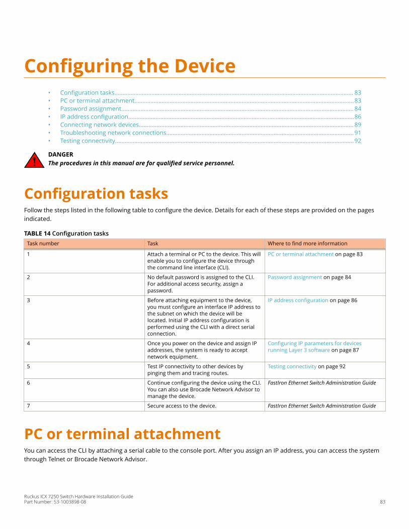
Configuring the Device• Configuration tasks..................................................................................................................................................... 83• PC or terminal attachment.........................................................................................................................................83• Password assignment................................................................................................................................................. 84• IP address configuration.............................................................................................................................................86• Connecting network devices...................................................................................................................................... 89• Troubleshooting network connections.....................................................................................................................91• Testing connectivity.....................................................................................................................................................92
DANGERThe procedures in this manual are for qualified service personnel.
Configuration tasksFollow the steps listed in the following table to configure the device. Details for each of these steps are provided on the pagesindicated.
TABLE 14 Configuration tasks Task number Task Where to find more information
1 Attach a terminal or PC to the device. This willenable you to configure the device throughthe command line interface (CLI).
PC or terminal attachment on page 83
2 No default password is assigned to the CLI.For additional access security, assign apassword.
Password assignment on page 84
3 Before attaching equipment to the device,you must configure an interface IP address tothe subnet on which the device will belocated. Initial IP address configuration isperformed using the CLI with a direct serialconnection.
IP address configuration on page 86
4 Once you power on the device and assign IPaddresses, the system is ready to acceptnetwork equipment.
Configuring IP parameters for devicesrunning Layer 3 software on page 87
5 Test IP connectivity to other devices bypinging them and tracing routes.
Testing connectivity on page 92
6 Continue configuring the device using the CLI.You can also use Brocade Network Advisor tomanage the device.
FastIron Ethernet Switch Administration Guide
7 Secure access to the device. FastIron Ethernet Switch Administration Guide
PC or terminal attachmentYou can access the CLI by attaching a serial cable to the console port. After you assign an IP address, you can access the systemthrough Telnet or Brocade Network Advisor.
Ruckus ICX 7250 Switch Hardware Installation GuidePart Number: 53-1003898-08 83

Complete the following steps to attach a management station to the console port.
1. Connect a PC or terminal to the console (mini-USB) port of the device.
To connect the console port to a DB9 port, you need a cable with mini-USB and DB9 connectors.
For information about locating the serial port, refer to Network and management interfaces on page 14.
The serial port has a mini-USB connector. For port pinout information, refer to Ruckus ICX 7250 Switch TechnicalSpecifications on page 95.
NOTEYou must run a terminal emulation program on the PC.
2. Launch the terminal emulation program and set the following session parameters:
• Baud: 9600 bps
• Data bits: 8
• Parity: None
• Stop bits: 1
• Flow control: None
The console serial communication port serves as a connection point for management by a PC or SNMP workstation.When you establish the serial connection to the system, press Enter to display the CLI prompt in the terminal emulationwindow, as shown in the following example.
device>
If you see this prompt, you are connected to the system and can proceed to Password assignment on page 84.
You can customize the prompt by changing the system name. For more information, refer to the Ruckus FastIronManagement Configuration Guide.
If you do not see the prompt, make sure the cable is securely connected to your PC and to the Ruckus device.
Check the settings in your terminal emulation program. In addition to the previously configured session settings, makesure the terminal emulation session is running on the same serial port you attached to the Ruckus device.
Password assignmentBy default, the CLI is not protected by passwords. To secure CLI access, Ruckus strongly recommends assigning passwords. Referto the FastIron Ethernet Switch Administration Guide.
NOTEYou can assign passwords using Brocade Network Advisor if an enable password for a Super User has been configuredon the device.
The CLI contains the following access levels:
• User EXEC: The level you enter when you first start a CLI session. At this level, you can view some system information butyou cannot configure system or port parameters.
• Privileged EXEC: This level is also called the Enable level and can be secured by a password. You can perform tasks suchas managing files on the flash module, saving the system configuration to flash, and clearing caches at this level.
• CONFIG: The configuration level. This level allows you to configure the system IP address and configure switching androuting features. To access the CONFIG mode, you must already be logged in to the privileged EXEC level.
Configuring the DevicePassword assignment
Ruckus ICX 7250 Switch Hardware Installation Guide84 Part Number: 53-1003898-08
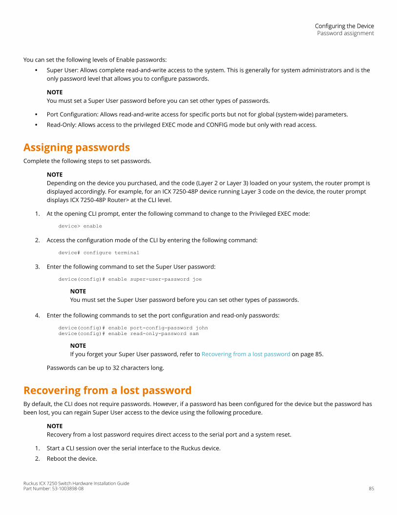
You can set the following levels of Enable passwords:
• Super User: Allows complete read-and-write access to the system. This is generally for system administrators and is theonly password level that allows you to configure passwords.
NOTEYou must set a Super User password before you can set other types of passwords.
• Port Configuration: Allows read-and-write access for specific ports but not for global (system-wide) parameters.
• Read-Only: Allows access to the privileged EXEC mode and CONFIG mode but only with read access.
Assigning passwordsComplete the following steps to set passwords.
NOTEDepending on the device you purchased, and the code (Layer 2 or Layer 3) loaded on your system, the router prompt isdisplayed accordingly. For example, for an ICX 7250-48P device running Layer 3 code on the device, the router promptdisplays ICX 7250-48P Router> at the CLI level.
1. At the opening CLI prompt, enter the following command to change to the Privileged EXEC mode:
device> enable
2. Access the configuration mode of the CLI by entering the following command:
device# configure terminal
3. Enter the following command to set the Super User password:
device(config)# enable super-user-password joe
NOTEYou must set the Super User password before you can set other types of passwords.
4. Enter the following commands to set the port configuration and read-only passwords:
device(config)# enable port-config-password johndevice(config)# enable read-only-password sam
NOTEIf you forget your Super User password, refer to Recovering from a lost password on page 85.
Passwords can be up to 32 characters long.
Recovering from a lost passwordBy default, the CLI does not require passwords. However, if a password has been configured for the device but the password hasbeen lost, you can regain Super User access to the device using the following procedure.
NOTERecovery from a lost password requires direct access to the serial port and a system reset.
1. Start a CLI session over the serial interface to the Ruckus device.
2. Reboot the device.
Configuring the DevicePassword assignment
Ruckus ICX 7250 Switch Hardware Installation GuidePart Number: 53-1003898-08 85
3. While the system is booting, before the initial system prompt appears, enter b to enter the boot monitor mode.
4. Enter no password. (You cannot abbreviate this command.)
5. Enter boot. This command causes the device to bypass the system password check.
After the console prompt reappears, assign a new password.
IP address configurationYou must configure at least one IP address using the serial connection to the CLI before you can manage the system using theother management interfaces.
Ruckus devices support both classical IP network masks (Class A, B, and C subnet masks, and so on) and Classless InterdomainRouting (CIDR) network prefix masks.
• To enter a classical IP network mask, enter the mask in IP address format. For example, enter "10.157.22.99255.255.255.0" for an IP address with a Class C subnet mask.
• To enter a prefix number for a network mask, enter a forward slash (/) and the number of bits in the mask immediatelyafter the IP address. For example, enter "10.157.22.99/24" for an IP address that has a network mask with 24 significant("mask") bits.
By default, the CLI displays network masks in classical IP address format (for example, 255.255.255.0). You can change thedisplay to the prefix format. Refer to the FastIron Ethernet Switch Administration Guide.
Devices running Layer 2 softwareUse the following procedure to configure an IP address on a device running Layer 2 software.
1. At the opening CLI prompt, enter enable.
device> enable
2. Enter the following command at the Privileged EXEC level prompt, and then press Enter . This command erases thefactory test configuration if still present.
device# erase startup-config
CAUTIONUse the erase startup-config command only for new systems. If you enter this command on a systemyou have already configured, the command erases the configuration. If you accidentally do erase theconfiguration on a configured system, enter the write memory command to save the runningconfiguration to the startup-config file.
3. Access the global configuration level of the CLI by entering the following command:
device# configure terminal
4. Configure the IP address and mask for the device.
device(config)# ip address 10.22.3.44 255.255.255.0
Configuring the DeviceIP address configuration
Ruckus ICX 7250 Switch Hardware Installation Guide86 Part Number: 53-1003898-08
5. Set a default gateway address for the device.
device(config)# ip default-gateway 10.22.3.1
NOTEYou do not need to assign a default gateway address for single subnet networks.
Devices running Layer 3 softwareBefore attaching equipment to a Ruckus ICX device running Layer 3 software, you must assign an interface IP address to thesubnet on which the device will be located. You must use the serial connection to assign the first IP address. For subsequentaddresses, you also can use the CLI through Telnet.
By default, you can configure up to 24 IP interfaces on each port, virtual interface, and loopback interface. You can increase thisamount to up to 64 IP subnet addresses per port by increasing the size of the subnet-per-interface table.
The following procedure shows how to add an IP address and mask to a router port.
1. At the opening CLI prompt, enter enable.
device> enable
2. Enter the following command at the privileged EXEC level prompt, and then press Enter . This command erases thefactory test configuration if still present.
device# erase startup-config
CAUTIONUse the erase startup-config command only for new systems. If you enter this command on a systemyou have already configured, the command erases the configuration. If you accidentally do erase theconfiguration on a configured system, enter the write memory command to save the runningconfiguration to the startup-config file.
3. Access the global configuration level of the CLI by entering the following command.
device# configure terminal device(config)#
4. Configure the IP addresses and mask addresses for the interfaces on the router.
device(config)# interface ethernet 2device(config)# ip address 10.22.3.44 255.255.255.0
NOTEYou can use the ip address ip-addr/mask-bits command if you know the subnet mask length. In the previousexample, you could enter ip address 10.22.3.44/24.
Use the secondary option of the ip address command parameter if you have already configured an IP address withinthe same subnet on the interface.
Configuring IP parameters for devices running Layer 3 softwareYou must configure IP parameters for devices running Layer 3 software.
Configuring the DeviceIP address configuration
Ruckus ICX 7250 Switch Hardware Installation GuidePart Number: 53-1003898-08 87
Configuring IP addresses
You can configure an IP address on the following types of Layer 3 interfaces:
• Ethernet port
• Virtual routing interface (also called a Virtual Ethernet or "VE")
• Loopback interface
By default, you can have up to 24 IP addresses on each interface, but you can increase this number to 128 IP addresses.
NOTEOnce you configure a virtual routing interface on a VLAN, you cannot configure Layer 3 interface parameters onindividual ports in the VLAN. Instead, you must configure the parameters on the virtual routing interface itself.
Assigning an IP address to an Ethernet port
Enter the following commands to assign an IP address to port 1/1/1.
device(config)# interface ethernet 1/1/1device(config)# ip address 10.45.6.1 255.255.255.0
You also can enter the IP address and mask in CIDR format.
device># ip address 10.45.6.1/24
Assigning an IP address to a loopback interface
Loopback interfaces are always up, regardless of the states of physical interfaces. They can add stability to the network becausethey are not subject to route flap problems that can occur due to unstable links between a Layer 3 device and other devices. Youcan configure up to four loopback interfaces on a Layer 3 device.
You can add up to 24 IP addresses to each loopback interface.
NOTEIf you configure the device to use a loopback interface to communicate with a BGP4 neighbor, you must also configure aloopback interface on the neighbor and configure the neighbor to use that loopback interface to communicate with theRuckus device.
To add a loopback interface, enter the interface loopback num and ip address num commands similar to the followingexample.
device(config)# exitdevice(config)# interface loopback 1device(config)# ip address 10.0.0.1/24
You can specify from 1 through the maximum number of virtual interfaces supported on the device by using the interfaceloopback num command.. To display the maximum number of virtual interfaces supported on the device, enter the showdefault values command.
Assigning an IP address to a virtual routing interface
A virtual interface is a logical port associated with a Layer 3 Virtual LAN (VLAN) configured on a Layer 3 device. You can configurerouting parameters on the virtual interface to enable the Layer 3 device to route protocol traffic from one Layer 3 VLAN to theother, without using an external router.
Configuring the DeviceIP address configuration
Ruckus ICX 7250 Switch Hardware Installation Guide88 Part Number: 53-1003898-08
NOTEThe device uses the lowest MAC address on the device (the MAC address of port 1 or 1/1/1) as the MAC address for allports within all virtual interfaces you configure on the device.
Enter commands similar to the following to add a virtual interface to a VLAN and configure an IP address on the interface.
device(config)# vlan 2 name IP-Subnet_10.1.2.1/24device(config-vlan-2)# untag 1/1/1 to 1/1/4device(config-vlan-2)# router-interface ve1device(config-vlan-2)# interface ve1device(config-vif-1)# ip address 10.1.2.1/24
The first two commands in this example create a Layer 3 protocol-based VLAN named "IP-Subnet_10.1.2.1/24" and add a rangeof untagged ports to the VLAN. The router-interface command creates virtual interface 1 as the routing interface for the VLAN.The last two commands change to the interface configuration level for the virtual interface and assign an IP address to theinterface.
Deleting an IP addressEnter a command similar to the following to delete an IP address.
device(config-if-1/1/1)# no ip address 10.1.2.1
This command deletes IP address 10.1.2.1. You do not need to enter the subnet mask.
To delete all IP addresses from an interface, enter the following command.
device(config-if-1/1/1)# no ip address *
Connecting network devicesRuckus devices support connections to other vendors’ routers, switches, and hubs, as well other Ruckus devices.
ConnectorsFor port pinouts, refer to Ruckus ICX 7250 Switch Technical Specifications on page 95.
Cable specificationsFor information about supported transceivers and cable lengths and types, refer to the Ruckus optics family datasheet.
Connecting to Ethernet or Fast Ethernet hubsFor copper connections to Ethernet hubs, a 10/100Base-TX or 1000Base-T switch, or another Ruckus device, a crossover cable isrequired as shown in the following figure. If the hub is equipped with an uplink port, it requires a straight-through cable insteadof a crossover cable.
NOTEThe 802.3ab standard (automatic MDI or MDIX detection) calls for automatic negotiation of the connection between two1000Base-T ports. In this case, a straight-through cable may work just as well as a crossover cable. For moreinformation, refer to the FastIron Ethernet Switch Administration Guide.
Configuring the DeviceConnecting network devices
Ruckus ICX 7250 Switch Hardware Installation GuidePart Number: 53-1003898-08 89
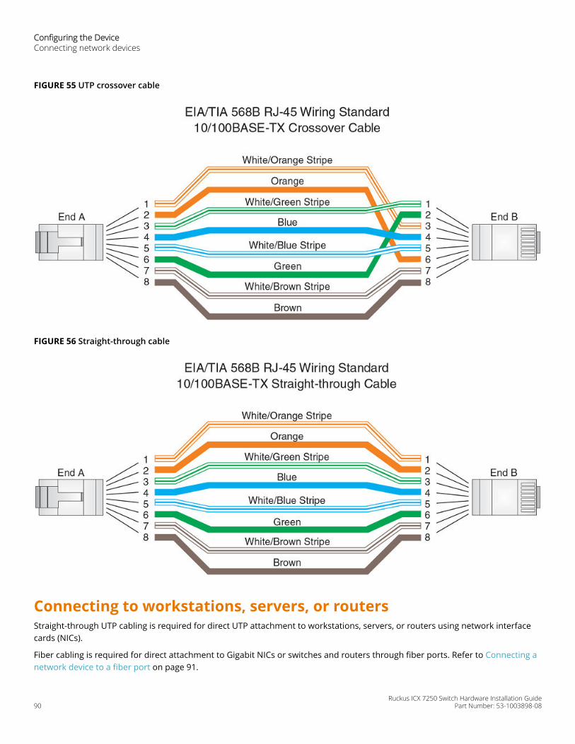
FIGURE 55 UTP crossover cable
FIGURE 56 Straight-through cable
Connecting to workstations, servers, or routersStraight-through UTP cabling is required for direct UTP attachment to workstations, servers, or routers using network interfacecards (NICs).
Fiber cabling is required for direct attachment to Gigabit NICs or switches and routers through fiber ports. Refer to Connecting anetwork device to a fiber port on page 91.
Configuring the DeviceConnecting network devices
Ruckus ICX 7250 Switch Hardware Installation Guide90 Part Number: 53-1003898-08
Automatic MDI or MDIX detectionAll 10/100 and 1000 Mbps Ethernet copper ports on the devices support automatic Media Dependent Interface (auto-MDI) orautomatic Media Dependent Interface Crossover (auto-MDIX) detection. Auto-MDI or auto-MDIX is enabled on all 10/100 and1000 Mbps copper ports by default. For each port, you can disable auto-MDI or auto-MDIX, designate the port as an MDI port, ordesignate the port as an MDIX port.
For more information about this feature and how to configure it, refer to the FastIron Ethernet Switch Administration Guide.
Connecting a network device to a fiber portFor direct attachment from the device to a Gigabit NIC, switch, or router, using a fiber-optic transceiver, you need fiber cablingwith an LC connector.
To connect the device to another network device using a fiber port, you must perform the following tasks:
• Install a fiber-optic transceiver (SFP or SFP+).
• Cable the fiber-optic transceiver.
For instructions on installing fiber-optic transceivers, refer to Installing a fiber-optic transceiver on page 110.
For instructions on cabling a fiber-optic transceiver, refer to Cabling a fiber-optic transceiver on page 111.
For instructions on cleaning a fiber-optic module, refer to Cleaning the fiber-optic connectors on page 112.
Troubleshooting network connections• For the indicated port, verify that both ends of the cabling (at the device and the connected device) are snug.
• Verify that the device and the connected device are both powered on and operating correctly.
• Verify that you have used the correct cable type for the connection:
– For twisted-pair connections to an end node, use straight-through cabling.– For fiber-optic connections, verify that the transmit port on the device is connected to the receive port on the
connected device, and that the receive port on the device is connected to the transmit port on the connected device.
• Use the CLI to verify that the port has not been disabled through a configuration change. If you have configured an IPaddress on the device, you also can use Brocade Network Advisor.
• If the other procedures do not resolve the problem, try using a different port or a different cable.
• If a 1-Gbps optic transceiver is inserted into an ICX 7250 device, you must configure the port using the speed-duplex1000-full-master command at the interface level.
Digital optical monitoringNOTE10 Gbps optical transceivers are not supported on ICX 7250-24G devices.
You can configure your device to monitor optical transceivers in the system, either globally or by specified port. When thisfeature is enabled, the system monitors the temperature and signal power levels for the optical transceivers in the specifiedports. Console messages and syslog messages are sent when optical operating conditions fall below or rise above the SFP andSFP+ manufacturer’s recommended thresholds. For more information about digital optical monitoring, refer to the FastIronEthernet Switch Administration Guide.
Configuring the DeviceTroubleshooting network connections
Ruckus ICX 7250 Switch Hardware Installation GuidePart Number: 53-1003898-08 91
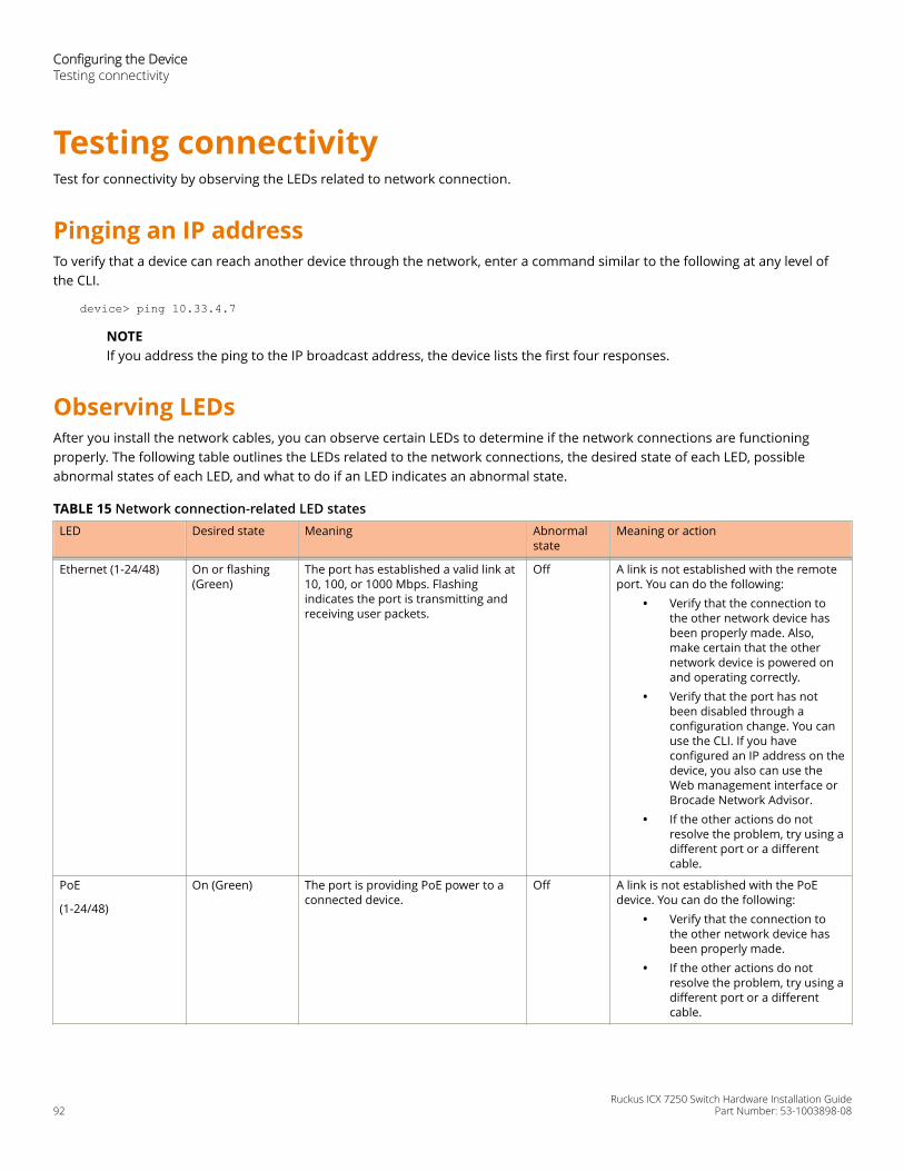
Testing connectivityTest for connectivity by observing the LEDs related to network connection.
Pinging an IP addressTo verify that a device can reach another device through the network, enter a command similar to the following at any level ofthe CLI.
device> ping 10.33.4.7
NOTEIf you address the ping to the IP broadcast address, the device lists the first four responses.
Observing LEDsAfter you install the network cables, you can observe certain LEDs to determine if the network connections are functioningproperly. The following table outlines the LEDs related to the network connections, the desired state of each LED, possibleabnormal states of each LED, and what to do if an LED indicates an abnormal state.
TABLE 15 Network connection-related LED states LED Desired state Meaning Abnormal
stateMeaning or action
Ethernet (1-24/48) On or flashing(Green)
The port has established a valid link at10, 100, or 1000 Mbps. Flashingindicates the port is transmitting andreceiving user packets.
Off A link is not established with the remoteport. You can do the following:
• Verify that the connection tothe other network device hasbeen properly made. Also,make certain that the othernetwork device is powered onand operating correctly.
• Verify that the port has notbeen disabled through aconfiguration change. You canuse the CLI. If you haveconfigured an IP address on thedevice, you also can use theWeb management interface orBrocade Network Advisor.
• If the other actions do notresolve the problem, try using adifferent port or a differentcable.
PoE
(1-24/48)
On (Green) The port is providing PoE power to aconnected device.
Off A link is not established with the PoEdevice. You can do the following:
• Verify that the connection tothe other network device hasbeen properly made.
• If the other actions do notresolve the problem, try using adifferent port or a differentcable.
Configuring the DeviceTesting connectivity
Ruckus ICX 7250 Switch Hardware Installation Guide92 Part Number: 53-1003898-08
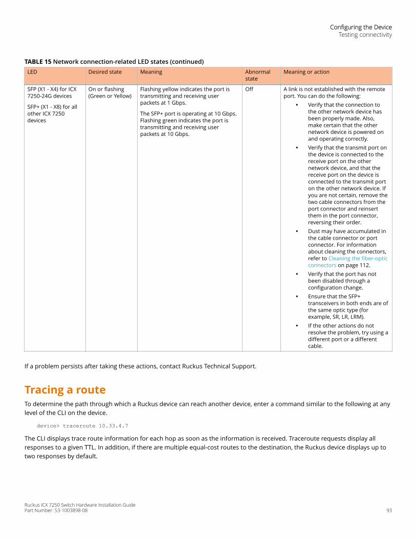
TABLE 15 Network connection-related LED states (continued)LED Desired state Meaning Abnormal
stateMeaning or action
SFP (X1 - X4) for ICX7250-24G devices
SFP+ (X1 - X8) for allother ICX 7250devices
On or flashing(Green or Yellow)
Flashing yellow indicates the port istransmitting and receiving userpackets at 1 Gbps.
The SFP+ port is operating at 10 Gbps.Flashing green indicates the port istransmitting and receiving userpackets at 10 Gbps.
Off A link is not established with the remoteport. You can do the following:
• Verify that the connection tothe other network device hasbeen properly made. Also,make certain that the othernetwork device is powered onand operating correctly.
• Verify that the transmit port onthe device is connected to thereceive port on the othernetwork device, and that thereceive port on the device isconnected to the transmit porton the other network device. Ifyou are not certain, remove thetwo cable connectors from theport connector and reinsertthem in the port connector,reversing their order.
• Dust may have accumulated inthe cable connector or portconnector. For informationabout cleaning the connectors,refer to Cleaning the fiber-opticconnectors on page 112.
• Verify that the port has notbeen disabled through aconfiguration change.
• Ensure that the SFP+transceivers in both ends are ofthe same optic type (forexample, SR, LR, LRM).
• If the other actions do notresolve the problem, try using adifferent port or a differentcable.
If a problem persists after taking these actions, contact Ruckus Technical Support.
Tracing a routeTo determine the path through which a Ruckus device can reach another device, enter a command similar to the following at anylevel of the CLI on the device.
device> traceroute 10.33.4.7
The CLI displays trace route information for each hop as soon as the information is received. Traceroute requests display allresponses to a given TTL. In addition, if there are multiple equal-cost routes to the destination, the Ruckus device displays up totwo responses by default.
Configuring the DeviceTesting connectivity
Ruckus ICX 7250 Switch Hardware Installation GuidePart Number: 53-1003898-08 93

Ruckus ICX 7250 Switch Hardware Installation Guide94 Part Number: 53-1003898-08
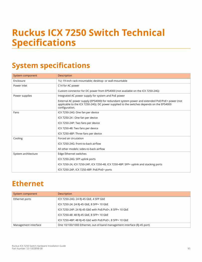
Ruckus ICX 7250 Switch TechnicalSpecifications
System specificationsSystem component Description
Enclosure 1U; 19-inch rack-mountable; desktop- or wall-mountable
Power inlet C14 for AC power
Custom connector for DC power from EPS4000 (not available on the ICX 7250-24G)
Power supplies Integrated AC power supply for system and PoE power
External AC power supply (EPS4000) for redundant system power and extended PoE/PoE+ power (notapplicable to the ICX 7250-24G). DC power supplied to the switches depends on the EPS4000configuration.
Fans ICX 7250-24G: One fan per device
ICX 7250-24 : One fan per device
ICX 7250-24P: Two fans per device
ICX 7250-48: Two fans per device
ICX 7250-48P: Three fans per device
Cooling Forced air circulation
ICX 7250-24G: front-to-back airflow
All other models: sides-to-back airflow
System architecture Edge Ethernet switches
ICX 7250-24G: SFP uplink ports
ICX 7250-24, ICX 7250-24P, ICX 7250-48, ICX 7250-48P: SFP+ uplink and stacking ports
ICX 7250-24P, ICX 7250-48P: PoE/PoE+ ports
EthernetSystem component Description
Ethernet ports ICX 7250-24G: 24 RJ-45 GbE, 4 SFP GbE
ICX 7250-24: 24 RJ-45 GbE, 8 SFP+ 10 GbE
ICX 7250-24P: 24 RJ-45 GbE with PoE/PoE+, 8 SFP+ 10 GbE
ICX 7250-48: 48 RJ-45 GbE, 8 SFP+ 10 GbE
ICX 7250-48P: 48 RJ-45 GbE with PoE/PoE+, 8 SFP+ 10 GbE
Management interface One 10/100/1000 Ethernet, out-of-band management interface (RJ-45 port)
Ruckus ICX 7250 Switch Hardware Installation GuidePart Number: 53-1003898-08 95
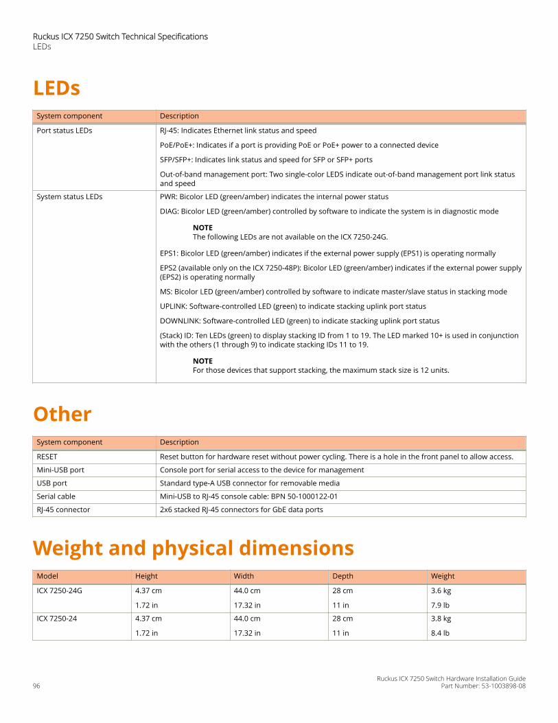
LEDsSystem component Description
Port status LEDs RJ-45: Indicates Ethernet link status and speed
PoE/PoE+: Indicates if a port is providing PoE or PoE+ power to a connected device
SFP/SFP+: Indicates link status and speed for SFP or SFP+ ports
Out-of-band management port: Two single-color LEDS indicate out-of-band management port link statusand speed
System status LEDs PWR: Bicolor LED (green/amber) indicates the internal power status
DIAG: Bicolor LED (green/amber) controlled by software to indicate the system is in diagnostic mode
NOTEThe following LEDs are not available on the ICX 7250-24G.
EPS1: Bicolor LED (green/amber) indicates if the external power supply (EPS1) is operating normally
EPS2 (available only on the ICX 7250-48P): Bicolor LED (green/amber) indicates if the external power supply(EPS2) is operating normally
MS: Bicolor LED (green/amber) controlled by software to indicate master/slave status in stacking mode
UPLINK: Software-controlled LED (green) to indicate stacking uplink port status
DOWNLINK: Software-controlled LED (green) to indicate stacking uplink port status
(Stack) ID: Ten LEDs (green) to display stacking ID from 1 to 19. The LED marked 10+ is used in conjunctionwith the others (1 through 9) to indicate stacking IDs 11 to 19.
NOTEFor those devices that support stacking, the maximum stack size is 12 units.
OtherSystem component Description
RESET Reset button for hardware reset without power cycling. There is a hole in the front panel to allow access.
Mini-USB port Console port for serial access to the device for management
USB port Standard type-A USB connector for removable media
Serial cable Mini-USB to RJ-45 console cable: BPN 50-1000122-01
RJ-45 connector 2x6 stacked RJ-45 connectors for GbE data ports
Weight and physical dimensionsModel Height Width Depth Weight
ICX 7250-24G 4.37 cm
1.72 in
44.0 cm
17.32 in
28 cm
11 in
3.6 kg
7.9 lb
ICX 7250-24 4.37 cm
1.72 in
44.0 cm
17.32 in
28 cm
11 in
3.8 kg
8.4 lb
Ruckus ICX 7250 Switch Technical SpecificationsLEDs
Ruckus ICX 7250 Switch Hardware Installation Guide96 Part Number: 53-1003898-08
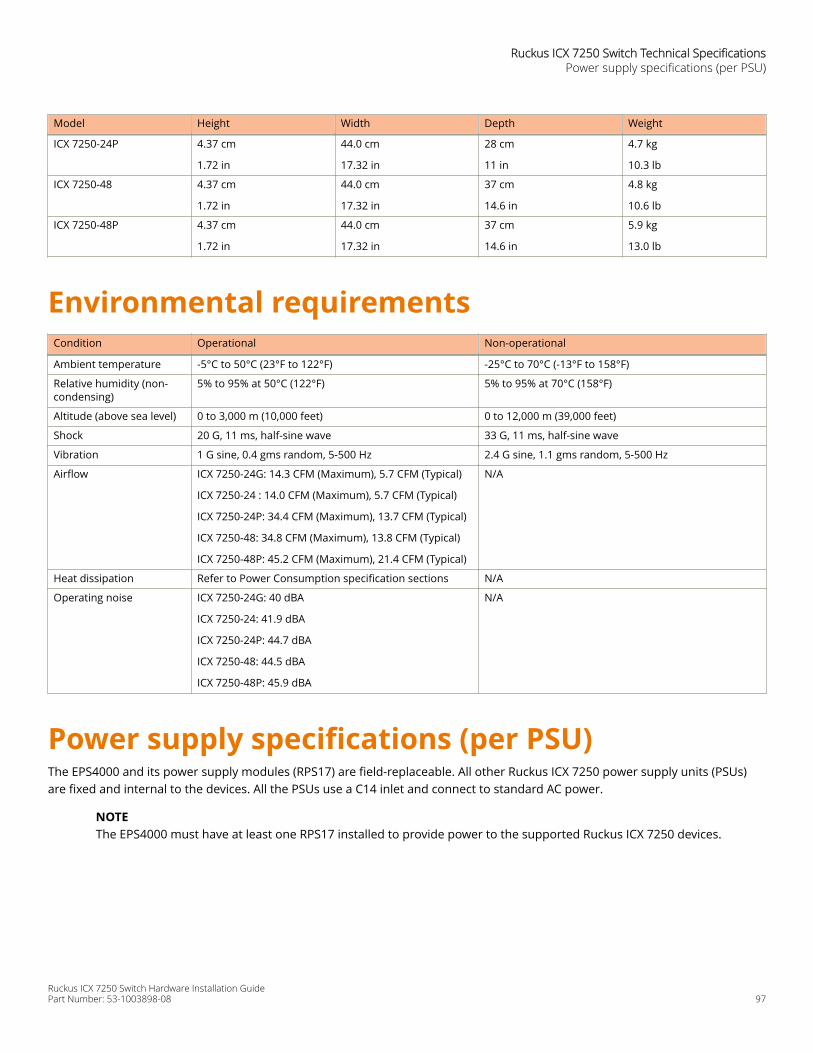
Model Height Width Depth Weight
ICX 7250-24P 4.37 cm
1.72 in
44.0 cm
17.32 in
28 cm
11 in
4.7 kg
10.3 lb
ICX 7250-48 4.37 cm
1.72 in
44.0 cm
17.32 in
37 cm
14.6 in
4.8 kg
10.6 lb
ICX 7250-48P 4.37 cm
1.72 in
44.0 cm
17.32 in
37 cm
14.6 in
5.9 kg
13.0 lb
Environmental requirementsCondition Operational Non-operational
Ambient temperature -5°C to 50°C (23°F to 122°F) -25°C to 70°C (-13°F to 158°F)
Relative humidity (non-condensing)
5% to 95% at 50°C (122°F) 5% to 95% at 70°C (158°F)
Altitude (above sea level) 0 to 3,000 m (10,000 feet) 0 to 12,000 m (39,000 feet)
Shock 20 G, 11 ms, half-sine wave 33 G, 11 ms, half-sine wave
Vibration 1 G sine, 0.4 gms random, 5-500 Hz 2.4 G sine, 1.1 gms random, 5-500 Hz
Airflow ICX 7250-24G: 14.3 CFM (Maximum), 5.7 CFM (Typical)
ICX 7250-24 : 14.0 CFM (Maximum), 5.7 CFM (Typical)
ICX 7250-24P: 34.4 CFM (Maximum), 13.7 CFM (Typical)
ICX 7250-48: 34.8 CFM (Maximum), 13.8 CFM (Typical)
ICX 7250-48P: 45.2 CFM (Maximum), 21.4 CFM (Typical)
N/A
Heat dissipation Refer to Power Consumption specification sections N/A
Operating noise ICX 7250-24G: 40 dBA
ICX 7250-24: 41.9 dBA
ICX 7250-24P: 44.7 dBA
ICX 7250-48: 44.5 dBA
ICX 7250-48P: 45.9 dBA
N/A
Power supply specifications (per PSU)The EPS4000 and its power supply modules (RPS17) are field-replaceable. All other Ruckus ICX 7250 power supply units (PSUs)are fixed and internal to the devices. All the PSUs use a C14 inlet and connect to standard AC power.
NOTEThe EPS4000 must have at least one RPS17 installed to provide power to the supported Ruckus ICX 7250 devices.
Ruckus ICX 7250 Switch Technical SpecificationsPower supply specifications (per PSU)
Ruckus ICX 7250 Switch Hardware Installation GuidePart Number: 53-1003898-08 97
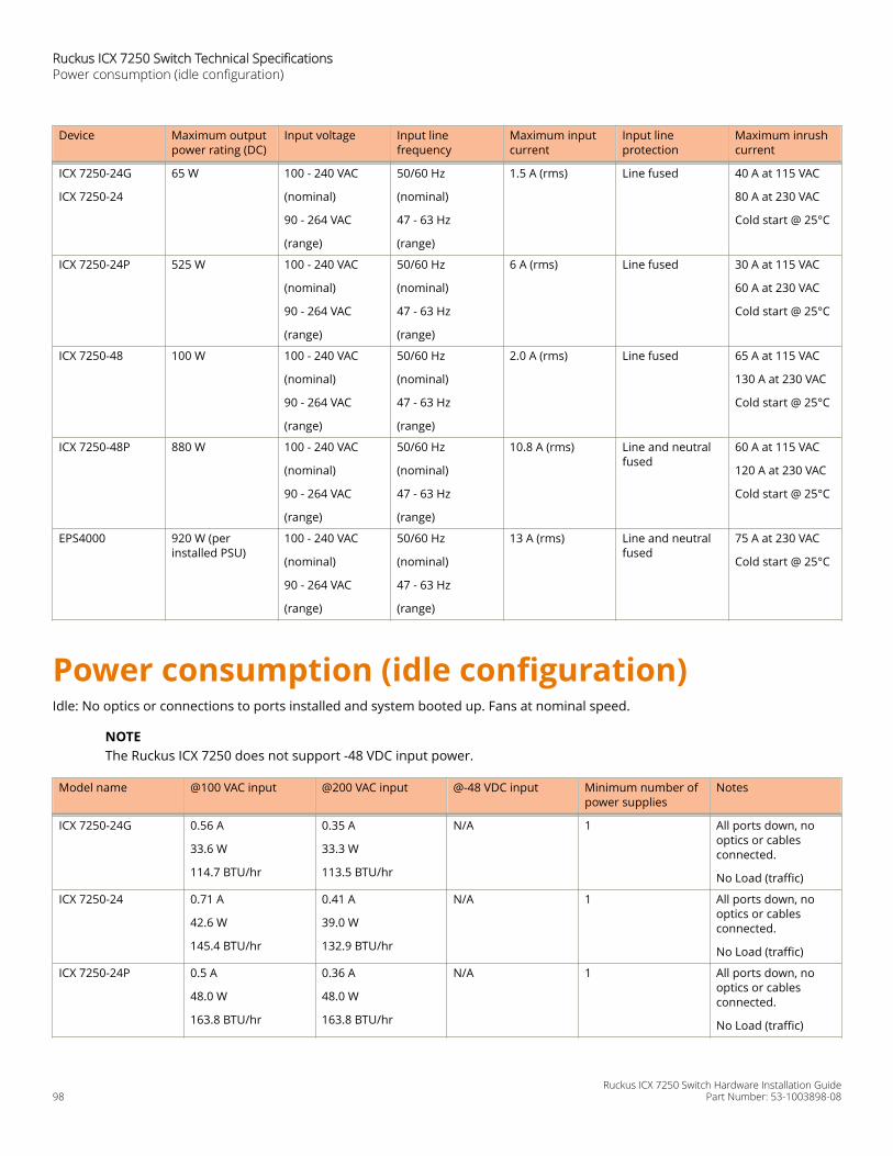
Device Maximum outputpower rating (DC)
Input voltage Input linefrequency
Maximum inputcurrent
Input lineprotection
Maximum inrushcurrent
ICX 7250-24G
ICX 7250-24
65 W 100 - 240 VAC
(nominal)
90 - 264 VAC
(range)
50/60 Hz
(nominal)
47 - 63 Hz
(range)
1.5 A (rms) Line fused 40 A at 115 VAC
80 A at 230 VAC
Cold start @ 25°C
ICX 7250-24P 525 W 100 - 240 VAC
(nominal)
90 - 264 VAC
(range)
50/60 Hz
(nominal)
47 - 63 Hz
(range)
6 A (rms) Line fused 30 A at 115 VAC
60 A at 230 VAC
Cold start @ 25°C
ICX 7250-48 100 W 100 - 240 VAC
(nominal)
90 - 264 VAC
(range)
50/60 Hz
(nominal)
47 - 63 Hz
(range)
2.0 A (rms) Line fused 65 A at 115 VAC
130 A at 230 VAC
Cold start @ 25°C
ICX 7250-48P 880 W 100 - 240 VAC
(nominal)
90 - 264 VAC
(range)
50/60 Hz
(nominal)
47 - 63 Hz
(range)
10.8 A (rms) Line and neutralfused
60 A at 115 VAC
120 A at 230 VAC
Cold start @ 25°C
EPS4000 920 W (perinstalled PSU)
100 - 240 VAC
(nominal)
90 - 264 VAC
(range)
50/60 Hz
(nominal)
47 - 63 Hz
(range)
13 A (rms) Line and neutralfused
75 A at 230 VAC
Cold start @ 25°C
Power consumption (idle configuration)Idle: No optics or connections to ports installed and system booted up. Fans at nominal speed.
NOTEThe Ruckus ICX 7250 does not support -48 VDC input power.
Model name @100 VAC input @200 VAC input @-48 VDC input Minimum number ofpower supplies
Notes
ICX 7250-24G 0.56 A
33.6 W
114.7 BTU/hr
0.35 A
33.3 W
113.5 BTU/hr
N/A 1 All ports down, nooptics or cablesconnected.
No Load (traffic)
ICX 7250-24 0.71 A
42.6 W
145.4 BTU/hr
0.41 A
39.0 W
132.9 BTU/hr
N/A 1 All ports down, nooptics or cablesconnected.
No Load (traffic)
ICX 7250-24P 0.5 A
48.0 W
163.8 BTU/hr
0.36 A
48.0 W
163.8 BTU/hr
N/A 1 All ports down, nooptics or cablesconnected.
No Load (traffic)
Ruckus ICX 7250 Switch Technical SpecificationsPower consumption (idle configuration)
Ruckus ICX 7250 Switch Hardware Installation Guide98 Part Number: 53-1003898-08
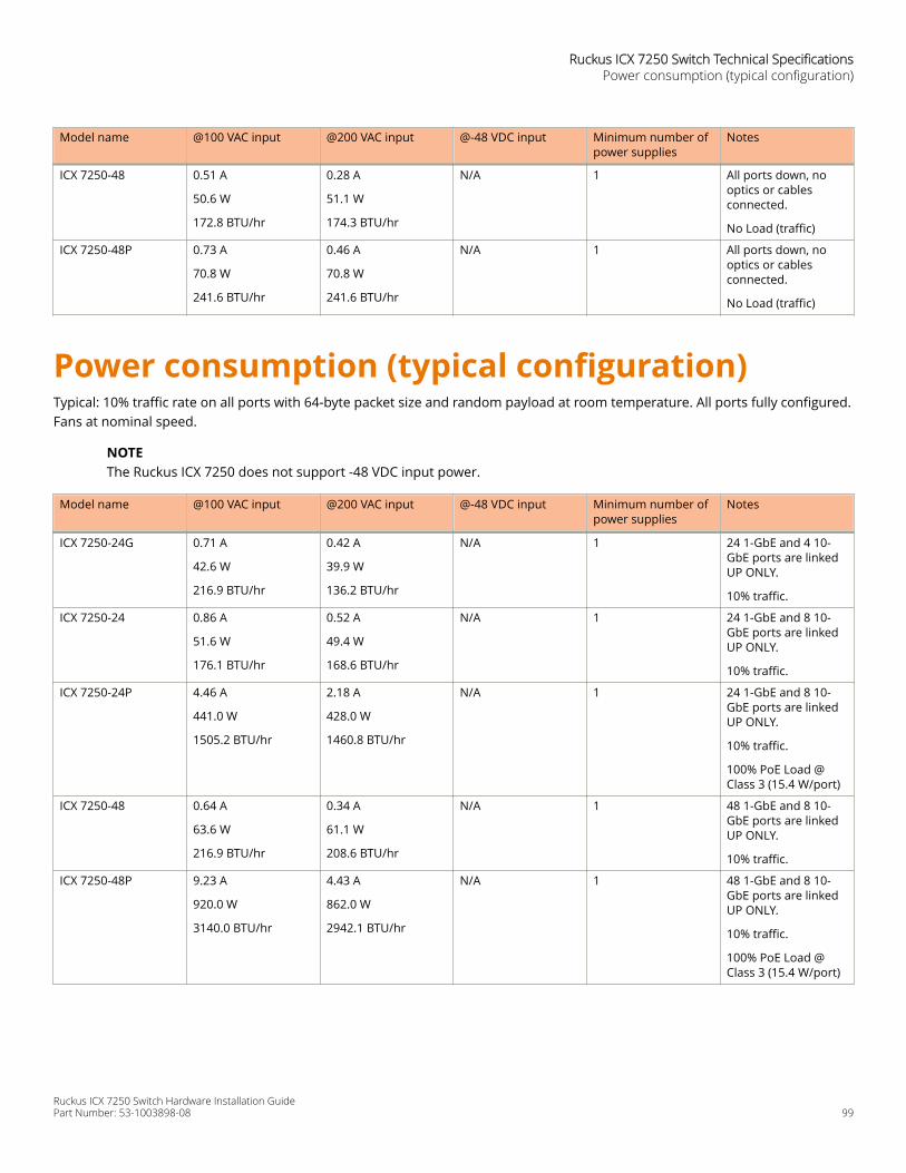
Model name @100 VAC input @200 VAC input @-48 VDC input Minimum number ofpower supplies
Notes
ICX 7250-48 0.51 A
50.6 W
172.8 BTU/hr
0.28 A
51.1 W
174.3 BTU/hr
N/A 1 All ports down, nooptics or cablesconnected.
No Load (traffic)
ICX 7250-48P 0.73 A
70.8 W
241.6 BTU/hr
0.46 A
70.8 W
241.6 BTU/hr
N/A 1 All ports down, nooptics or cablesconnected.
No Load (traffic)
Power consumption (typical configuration)Typical: 10% traffic rate on all ports with 64-byte packet size and random payload at room temperature. All ports fully configured.Fans at nominal speed.
NOTEThe Ruckus ICX 7250 does not support -48 VDC input power.
Model name @100 VAC input @200 VAC input @-48 VDC input Minimum number ofpower supplies
Notes
ICX 7250-24G 0.71 A
42.6 W
216.9 BTU/hr
0.42 A
39.9 W
136.2 BTU/hr
N/A 1 24 1-GbE and 4 10-GbE ports are linkedUP ONLY.
10% traffic.
ICX 7250-24 0.86 A
51.6 W
176.1 BTU/hr
0.52 A
49.4 W
168.6 BTU/hr
N/A 1 24 1-GbE and 8 10-GbE ports are linkedUP ONLY.
10% traffic.
ICX 7250-24P 4.46 A
441.0 W
1505.2 BTU/hr
2.18 A
428.0 W
1460.8 BTU/hr
N/A 1 24 1-GbE and 8 10-GbE ports are linkedUP ONLY.
10% traffic.
100% PoE Load @Class 3 (15.4 W/port)
ICX 7250-48 0.64 A
63.6 W
216.9 BTU/hr
0.34 A
61.1 W
208.6 BTU/hr
N/A 1 48 1-GbE and 8 10-GbE ports are linkedUP ONLY.
10% traffic.
ICX 7250-48P 9.23 A
920.0 W
3140.0 BTU/hr
4.43 A
862.0 W
2942.1 BTU/hr
N/A 1 48 1-GbE and 8 10-GbE ports are linkedUP ONLY.
10% traffic.
100% PoE Load @Class 3 (15.4 W/port)
Ruckus ICX 7250 Switch Technical SpecificationsPower consumption (typical configuration)
Ruckus ICX 7250 Switch Hardware Installation GuidePart Number: 53-1003898-08 99
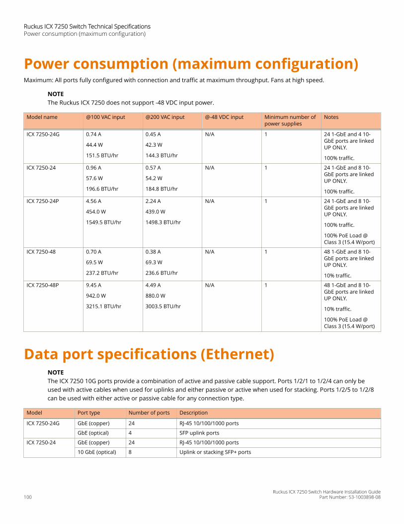
Power consumption (maximum configuration)Maximum: All ports fully configured with connection and traffic at maximum throughput. Fans at high speed.
NOTEThe Ruckus ICX 7250 does not support -48 VDC input power.
Model name @100 VAC input @200 VAC input @-48 VDC input Minimum number ofpower supplies
Notes
ICX 7250-24G 0.74 A
44.4 W
151.5 BTU/hr
0.45 A
42.3 W
144.3 BTU/hr
N/A 1 24 1-GbE and 4 10-GbE ports are linkedUP ONLY.
100% traffic.
ICX 7250-24 0.96 A
57.6 W
196.6 BTU/hr
0.57 A
54.2 W
184.8 BTU/hr
N/A 1 24 1-GbE and 8 10-GbE ports are linkedUP ONLY.
100% traffic.
ICX 7250-24P 4.56 A
454.0 W
1549.5 BTU/hr
2.24 A
439.0 W
1498.3 BTU/hr
N/A 1 24 1-GbE and 8 10-GbE ports are linkedUP ONLY.
100% traffic.
100% PoE Load @Class 3 (15.4 W/port)
ICX 7250-48 0.70 A
69.5 W
237.2 BTU/hr
0.38 A
69.3 W
236.6 BTU/hr
N/A 1 48 1-GbE and 8 10-GbE ports are linkedUP ONLY.
10% traffic.
ICX 7250-48P 9.45 A
942.0 W
3215.1 BTU/hr
4.49 A
880.0 W
3003.5 BTU/hr
N/A 1 48 1-GbE and 8 10-GbE ports are linkedUP ONLY.
10% traffic.
100% PoE Load @Class 3 (15.4 W/port)
Data port specifications (Ethernet)NOTEThe ICX 7250 10G ports provide a combination of active and passive cable support. Ports 1/2/1 to 1/2/4 can only beused with active cables when used for uplinks and either passive or active when used for stacking. Ports 1/2/5 to 1/2/8can be used with either active or passive cable for any connection type.
Model Port type Number of ports Description
ICX 7250-24G GbE (copper) 24 RJ-45 10/100/1000 ports
GbE (optical) 4 SFP uplink ports
ICX 7250-24 GbE (copper) 24 RJ-45 10/100/1000 ports
10 GbE (optical) 8 Uplink or stacking SFP+ ports
Ruckus ICX 7250 Switch Technical SpecificationsPower consumption (maximum configuration)
Ruckus ICX 7250 Switch Hardware Installation Guide100 Part Number: 53-1003898-08
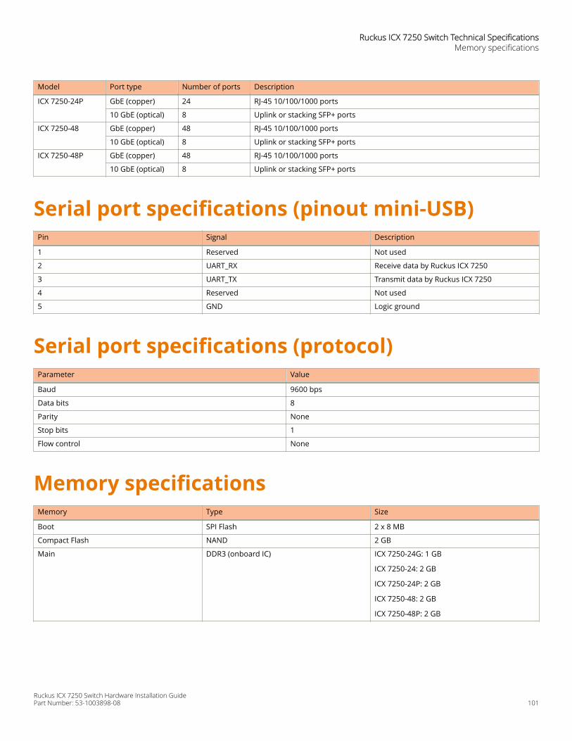
Model Port type Number of ports Description
ICX 7250-24P GbE (copper) 24 RJ-45 10/100/1000 ports
10 GbE (optical) 8 Uplink or stacking SFP+ ports
ICX 7250-48 GbE (copper) 48 RJ-45 10/100/1000 ports
10 GbE (optical) 8 Uplink or stacking SFP+ ports
ICX 7250-48P GbE (copper) 48 RJ-45 10/100/1000 ports
10 GbE (optical) 8 Uplink or stacking SFP+ ports
Serial port specifications (pinout mini-USB)Pin Signal Description
1 Reserved Not used
2 UART_RX Receive data by Ruckus ICX 7250
3 UART_TX Transmit data by Ruckus ICX 7250
4 Reserved Not used
5 GND Logic ground
Serial port specifications (protocol)Parameter Value
Baud 9600 bps
Data bits 8
Parity None
Stop bits 1
Flow control None
Memory specificationsMemory Type Size
Boot SPI Flash 2 x 8 MB
Compact Flash NAND 2 GB
Main DDR3 (onboard IC) ICX 7250-24G: 1 GB
ICX 7250-24: 2 GB
ICX 7250-24P: 2 GB
ICX 7250-48: 2 GB
ICX 7250-48P: 2 GB
Ruckus ICX 7250 Switch Technical SpecificationsMemory specifications
Ruckus ICX 7250 Switch Hardware Installation GuidePart Number: 53-1003898-08 101

Regulatory compliance (EMC)• FCC Part 15, Subpart B (Class A)
• EN 55022 (CE mark) (Class A)
• EN 55024 (CE mark) (Immunity) for Information Technology Equipment
• ICES-003 (Canada) (Class A)
• AS/NZ 55022 (Australia) (Class A)
• VCCI ( Japan) (Class A)
• EN 61000-3-2
• EN 61000-3-3
• EN 61000-6-1
Regulatory compliance (safety)• CAN/CSA-C22.2 No. 60950/UL 60950
• EN 60825 Safety of Laser Products
• EN 60950/IEC 60950 Safety of Information Technology Equipment
Regulatory compliance (environmental)• 2011/65/EU - Restriction of the use of certain hazardous substance in electrical and electronic equipment (EU RoHS).
• 2012/19/EU - Waste electrical and electronic equipment (EU WEEE).
• 94/62/EC - packaging and packaging waste (EU).
• 2006/66/EC - batteries and accumulators and waste batteries and accumulators (EU battery directive).
• 1907/2006 of the European Parliament and of the Council of 18 December 2006 concerning the Registration, Evaluation,Authorisation and Restriction of Chemicals (EU REACH).
• Section 1502 of the Dodd-Frank Wall Street Reform and Consumer Protection Act of 2010 - U.S. Conflict Minerals.
• 30/2011/TT-BCT - Vietnam circular.
• SJ/T 11363-2006 Requirements for Concentration Limits for Certain Hazardous Substances in EIPs (China).
• SJ/T 11364-2006 Marking for the Control of Pollution Caused by EIPs (China).
Ruckus ICX 7250 Switch Technical SpecificationsRegulatory compliance (EMC)
Ruckus ICX 7250 Switch Hardware Installation Guide102 Part Number: 53-1003898-08
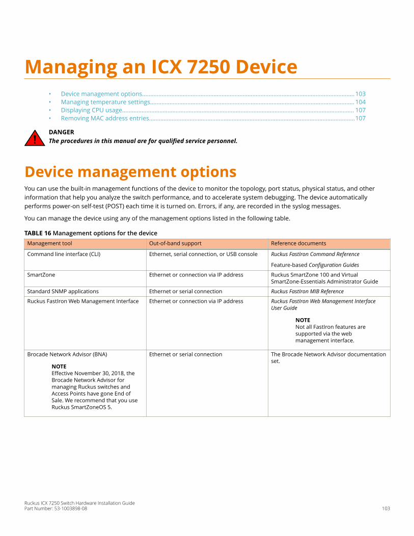
Managing an ICX 7250 Device• Device management options...................................................................................................................................103• Managing temperature settings.............................................................................................................................. 104• Displaying CPU usage............................................................................................................................................... 107• Removing MAC address entries...............................................................................................................................107
DANGERThe procedures in this manual are for qualified service personnel.
Device management optionsYou can use the built-in management functions of the device to monitor the topology, port status, physical status, and otherinformation that help you analyze the switch performance, and to accelerate system debugging. The device automaticallyperforms power-on self-test (POST) each time it is turned on. Errors, if any, are recorded in the syslog messages.
You can manage the device using any of the management options listed in the following table.
TABLE 16 Management options for the deviceManagement tool Out-of-band support Reference documents
Command line interface (CLI) Ethernet, serial connection, or USB console Ruckus FastIron Command Reference
Feature-based Configuration Guides
SmartZone Ethernet or connection via IP address Ruckus SmartZone 100 and VirtualSmartZone-Essentials Administrator Guide
Standard SNMP applications Ethernet or serial connection Ruckus FastIron MIB Reference
Ruckus FastIron Web Management Interface Ethernet or connection via IP address Ruckus FastIron Web Management InterfaceUser Guide
NOTENot all FastIron features aresupported via the webmanagement interface.
Brocade Network Advisor (BNA)
NOTEEffective November 30, 2018, theBrocade Network Advisor formanaging Ruckus switches andAccess Points have gone End ofSale. We recommend that you useRuckus SmartZoneOS 5.
Ethernet or serial connection The Brocade Network Advisor documentationset.
Ruckus ICX 7250 Switch Hardware Installation GuidePart Number: 53-1003898-08 103
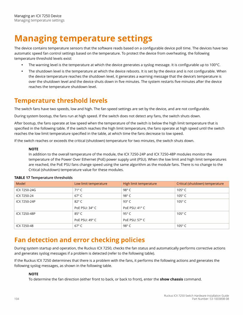
Managing temperature settingsThe device contains temperature sensors that the software reads based on a configurable device poll time. The devices have twoautomatic speed fan control settings based on the temperature. To protect the device from overheating, the followingtemperature threshold levels exist:
• The warning level is the temperature at which the device generates a syslog message. It is configurable up to 100°C.
• The shutdown level is the temperature at which the device reboots. It is set by the device and is not configurable. Whenthe device temperature reaches the shutdown level, it generates a warning message that the device’s temperature isover the shutdown level and the device shuts down in five minutes. The system restarts five minutes after the devicereaches the temperature shutdown level.
Temperature threshold levelsThe switch fans have two speeds, low and high. The fan speed settings are set by the device, and are not configurable.
During system bootup, the fans run at high speed. If the switch does not detect any fans, the switch shuts down.
After bootup, the fans operate at low speed when the temperature of the switch is below the high limit temperature that isspecified in the following table. If the switch reaches the high limit temperature, the fans operate at high speed until the switchreaches the low limit temperature specified in the table, at which time the fans decrease to low speed.
If the switch reaches or exceeds the critical (shutdown) temperature for two minutes, the switch shuts down.
NOTEIn addition to the overall temperature of the module, the ICX 7250-24P and ICX 7250-48P modules monitor thetemperature of the Power Over Ethernet (PoE) power supply unit (PSU). When the low limit and high limit temperaturesare reached, the PoE PSU fans change speed using the same algorithm as the module fans. There is no change to theCritical (shutdown) temperature value for these modules.
TABLE 17 Temperature thresholdsModel Low limit temperature High limit temperature Critical (shutdown) temperature
ICX 7250-24G 71° C 98° C 105° C
ICX 7250-24 67° C 98° C 105° C
ICX 7250-24P 82° C
PoE PSU: 34° C
93° C
PoE PSU: 41° C
105° C
ICX 7250-48P 85° C
PoE PSU: 49° C
95° C
PoE PSU: 57° C
105° C
ICX 7250-48 67° C 98° C 105° C
Fan detection and error checking policiesDuring system startup and operation, the Ruckus ICX 7250, checks the fan status and automatically performs corrective actionsand generates syslog messages if a problem is detected (refer to the following table).
If the Ruckus ICX 7250 determines that there is a problem with the fans, it performs the following actions and generates thefollowing syslog messages, as shown in the following table.
NOTETo determine the fan direction (either front to back, or back to front), enter the show chassis command.
Managing an ICX 7250 DeviceManaging temperature settings
Ruckus ICX 7250 Switch Hardware Installation Guide104 Part Number: 53-1003898-08
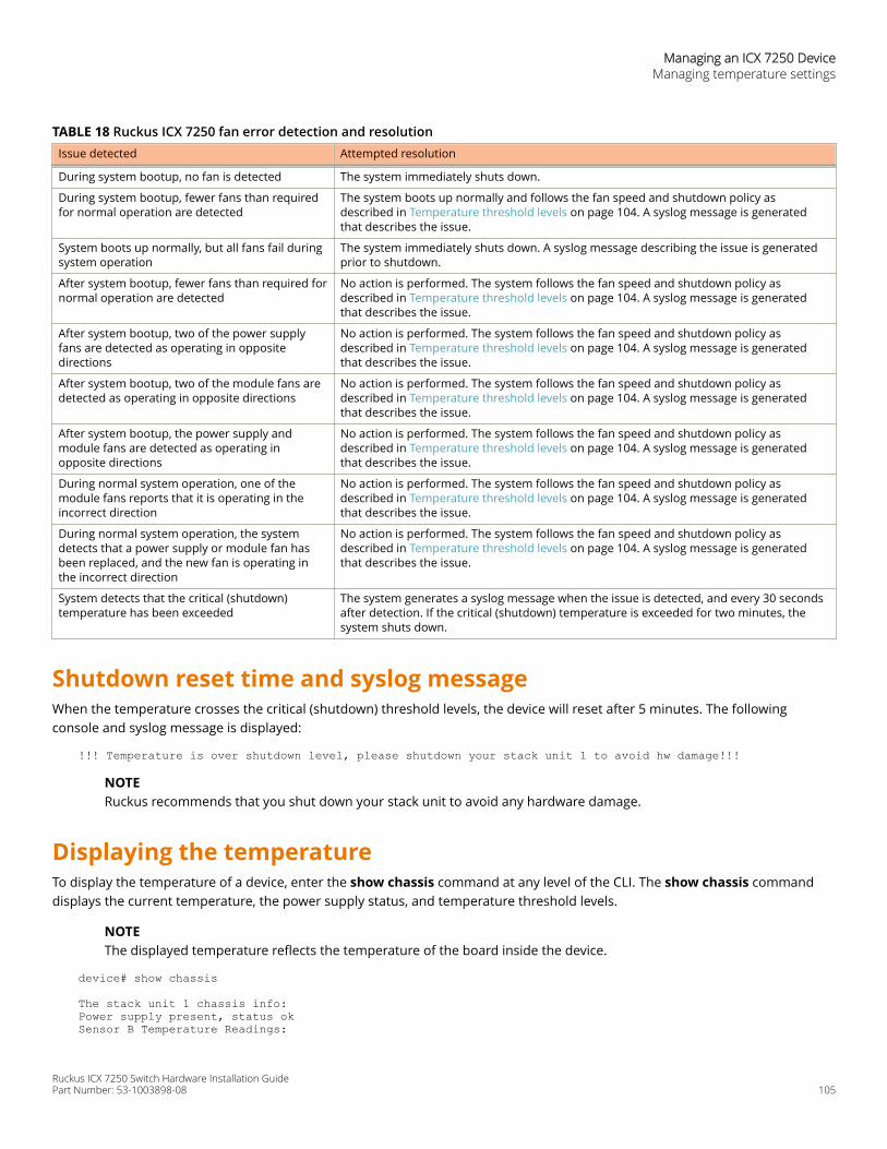
TABLE 18 Ruckus ICX 7250 fan error detection and resolutionIssue detected Attempted resolution
During system bootup, no fan is detected The system immediately shuts down.
During system bootup, fewer fans than requiredfor normal operation are detected
The system boots up normally and follows the fan speed and shutdown policy asdescribed in Temperature threshold levels on page 104. A syslog message is generatedthat describes the issue.
System boots up normally, but all fans fail duringsystem operation
The system immediately shuts down. A syslog message describing the issue is generatedprior to shutdown.
After system bootup, fewer fans than required fornormal operation are detected
No action is performed. The system follows the fan speed and shutdown policy asdescribed in Temperature threshold levels on page 104. A syslog message is generatedthat describes the issue.
After system bootup, two of the power supplyfans are detected as operating in oppositedirections
No action is performed. The system follows the fan speed and shutdown policy asdescribed in Temperature threshold levels on page 104. A syslog message is generatedthat describes the issue.
After system bootup, two of the module fans aredetected as operating in opposite directions
No action is performed. The system follows the fan speed and shutdown policy asdescribed in Temperature threshold levels on page 104. A syslog message is generatedthat describes the issue.
After system bootup, the power supply andmodule fans are detected as operating inopposite directions
No action is performed. The system follows the fan speed and shutdown policy asdescribed in Temperature threshold levels on page 104. A syslog message is generatedthat describes the issue.
During normal system operation, one of themodule fans reports that it is operating in theincorrect direction
No action is performed. The system follows the fan speed and shutdown policy asdescribed in Temperature threshold levels on page 104. A syslog message is generatedthat describes the issue.
During normal system operation, the systemdetects that a power supply or module fan hasbeen replaced, and the new fan is operating inthe incorrect direction
No action is performed. The system follows the fan speed and shutdown policy asdescribed in Temperature threshold levels on page 104. A syslog message is generatedthat describes the issue.
System detects that the critical (shutdown)temperature has been exceeded
The system generates a syslog message when the issue is detected, and every 30 secondsafter detection. If the critical (shutdown) temperature is exceeded for two minutes, thesystem shuts down.
Shutdown reset time and syslog messageWhen the temperature crosses the critical (shutdown) threshold levels, the device will reset after 5 minutes. The followingconsole and syslog message is displayed:
!!! Temperature is over shutdown level, please shutdown your stack unit 1 to avoid hw damage!!!
NOTERuckus recommends that you shut down your stack unit to avoid any hardware damage.
Displaying the temperatureTo display the temperature of a device, enter the show chassis command at any level of the CLI. The show chassis commanddisplays the current temperature, the power supply status, and temperature threshold levels.
NOTEThe displayed temperature reflects the temperature of the board inside the device.
device# show chassis
The stack unit 1 chassis info: Power supply present, status okSensor B Temperature Readings:
Managing an ICX 7250 DeviceManaging temperature settings
Ruckus ICX 7250 Switch Hardware Installation GuidePart Number: 53-1003898-08 105

Current temperature : 55.0 deg-CSensor A Temperature Readings: Current temperature : 50.0 deg-C Warning level.......: 71.0 deg-C Shutdown level......: 105.0 deg-CBoot Prom MAC : 748e.f8ea.0360Management MAC: 748e.f8ea.0360=====
Displaying syslog messages for temperatureThe software sends a syslog message and an SNMP trap if the temperature crosses the warning or shutdown thresholds. If youhave configured the device to use a syslog server or SNMP trap receiver, refer to the documentation for the server or receiver.
To display the system log, enter the show log command at any CLI level.
device# show log
Syslog logging: enabled (0 messages dropped, 0 flushes, 0 overruns)Buffer logging: level ACDMEINW, 20 messages loggedlevel code: A=alert C=critical D=debugging M=emergency E=error I=informational N=notification W=warningStatic Log Buffer:1d02h07m29s:A:System: Stack unit 1 Temperature 60.0 C degrees, warning level 55.0 C degrees, shutdown level 65.0 C degrees1d02h07m29s:W:System: Temperature is over warning level on unit 1Dec 1 10:16:34:A:System: Stack unit 2 Temperature 46.0 C degrees, warning level 70.0 C degrees, shutdown level 80.0 C degreesDec 1 10:16:34:A:System: Temperature on Unit 2 is over shutdown level, system is going to be reset in 2 secondsDynamic Log Buffer (50 lines):0d00h00m53s:I:STP: VLAN 1 Port 1/2/2 Bridge TC Event (FwdDlyExpiry)0d00h00m53s:I:STP: VLAN 1 Port 1/2/2 STP State -> FORWARDING (FwdDlyExpiry)0d00h00m37s:I:STP: VLAN 1 Port 1/2/2 STP State -> LEARNING (FwdDlyExpiry)0d00h00m26s:I:STP: VLAN 1 Port 1/2/3 STP State -> FORWARDING (FwdDlyExpiry)0d00h00m26s:I:STP: VLAN 1 Port 1/1/1 STP State -> FORWARDING (FwdDlyExpiry)0d00h00m24s:I:STP: VLAN 1 Port 1/2/3 STP State -> LEARNING (FwdDlyExpiry)0d00h00m24s:I:STP: VLAN 1 Port 1/1/1 STP State -> LEARNING (FwdDlyExpiry)0d00h00m23s:I:STP: VLAN 1 Port 1/2/4 STP State -> BLOCKING (MakeBlking)0d00h00m22s:I:System: Interface ethernet 1/2/4, state up0d00h00m22s:I:STP: VLAN 1 Port 1/2/4 STP State -> LISTENING (MakeFwding)0d00h00m22s:I:System: Interface ethernet 1/2/3, state up
Changing the temperature warning levelTo change the temperature at which the device sends a syslog message and an SNMP trap, enter the temperature warningstack-id value command at the privileged EXEC level of the CLI.
device# temperature warning 1 82
The stack-id variable can be a value from 1 through 12.
The value variable is the temperature warning level, in Celsius. You cannot set this level higher than the maximum value allowedby your device. The temperature warning level must be at least five degrees Celsius less than the temperature shutdown level,which is automatically set by the device.
The following console and syslog message is displayed when the temperature reaches the warning level:!!! Temperature is over warning level on stack unit 1!!!
Managing an ICX 7250 DeviceManaging temperature settings
Ruckus ICX 7250 Switch Hardware Installation Guide106 Part Number: 53-1003898-08
Changing the temperature poll timeBy default, the software polls the temperature sensor every 60 seconds to get the current temperature. This poll rate iscontrolled by the device poll time, which also controls how often the software polls other system components.
To change the poll time, enter the chassis poll-time value command at the global configuration level.
device(config)# chassis poll-time 200
The value variable can be from 0 through 65535 seconds.
Displaying CPU usageYou can display the amount of the CPU in use. To do so, enter the show cpu command at any level of the CLI.
device# show cpu
20 percent busy, from 318 sec ago1 sec avg: 2 percent busy5 sec avg: 1 percent busy60 sec avg: 1 percent busy300 sec avg: 1 percent busy
Removing MAC address entriesYou can remove the following types of learned MAC address entries from the system MAC address table:
• All MAC address entries
• All MAC address entries for a specified Ethernet port
• All MAC address entries for a specified VLAN
• A specified MAC address entry in all VLANs
For example, to remove entries for the MAC address 00-00-00 in all VLANs, enter the following command at the privileged EXEClevel of the CLI.
device# clear mac-address 00-00-00
Syntax: clear mac-address [ mac-address | ethernet port-num | vlan number ]
If you enter the clear mac-address command without any parameters, the software removes all MAC entries.
Use the clear mac-address mac-address command to remove a specified MAC address from all VLANs. Specify the MAC addressin the following format: HHHH.HHHH.HHHH.
Use the clear mac-address ethernet port-num command to remove all MAC addresses for a specified Ethernet port.
Use the clear mac-address vlan number command to remove all MAC addresses for a specified VLAN.
Managing an ICX 7250 DeviceRemoving MAC address entries
Ruckus ICX 7250 Switch Hardware Installation GuidePart Number: 53-1003898-08 107

Ruckus ICX 7250 Switch Hardware Installation Guide108 Part Number: 53-1003898-08
Hardware Maintenance Schedule• Pre-connection cleaning recommendations..........................................................................................................109• Copper or fiber-optic module replacement...........................................................................................................109• Cabling a fiber-optic transceiver..............................................................................................................................112
DANGERThe procedures in this manual are for qualified service personnel.
Pre-connection cleaning recommendationsTheICX 7250 devices require minimal maintenance for their hardware components. However, Ruckus recommends cleaning thefiber-optic connectors on a fiber-optic port and the connected fiber cable each time you disconnect or reconnect the cable asshown in Cleaning the fiber-optic connectors on page 112.
Copper or fiber-optic module replacementYou can replace the copper and fiber-optic modules (SFP and SFP+ transceivers). You can remove an SFP or an SFP+ transceiverfrom a slot and replace it with a new one while the ICX 7250 device is powered on and running.
Removing a copper or fiber-optic moduleYou can remove a copper or fiber SFP or SFP+ transceiver from a slot while the ICX 7250 device is powered on and running.
While removing a copper or fiber-optic module, be sure to wear an ESD wrist strap with a plug that can be inserted in the ESDconnector on the ICX 7250 device.
DANGERFor safety reasons, the ESD wrist strap should contain a series 1 megaohm resistor.
To remove a copper or fiber-optic module from an SFP or SFP+ slot, complete the following steps.
1. Put on the ESD wrist strap and ground yourself by attaching the clip end to a metal surface (such as an equipment rack).
2. Disconnect the copper or fiber cable connector from the port connector.
Ruckus ICX 7250 Switch Hardware Installation GuidePart Number: 53-1003898-08 109
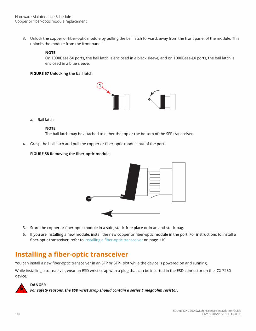
3. Unlock the copper or fiber-optic module by pulling the bail latch forward, away from the front panel of the module. Thisunlocks the module from the front panel.
NOTEOn 1000Base-SX ports, the bail latch is enclosed in a black sleeve, and on 1000Base-LX ports, the bail latch isenclosed in a blue sleeve.
FIGURE 57 Unlocking the bail latch
a. Bail latch
NOTEThe bail latch may be attached to either the top or the bottom of the SFP transceiver.
4. Grasp the bail latch and pull the copper or fiber-optic module out of the port.
FIGURE 58 Removing the fiber-optic module
5. Store the copper or fiber-optic module in a safe, static-free place or in an anti-static bag.
6. If you are installing a new module, install the new copper or fiber-optic module in the port. For instructions to install afiber-optic transceiver, refer to Installing a fiber-optic transceiver on page 110.
Installing a fiber-optic transceiverYou can install a new fiber-optic transceiver in an SFP or SFP+ slot while the device is powered on and running.
While installing a transceiver, wear an ESD wrist strap with a plug that can be inserted in the ESD connector on the ICX 7250device.
DANGERFor safety reasons, the ESD wrist strap should contain a series 1 megaohm resistor.
Hardware Maintenance ScheduleCopper or fiber-optic module replacement
Ruckus ICX 7250 Switch Hardware Installation Guide110 Part Number: 53-1003898-08
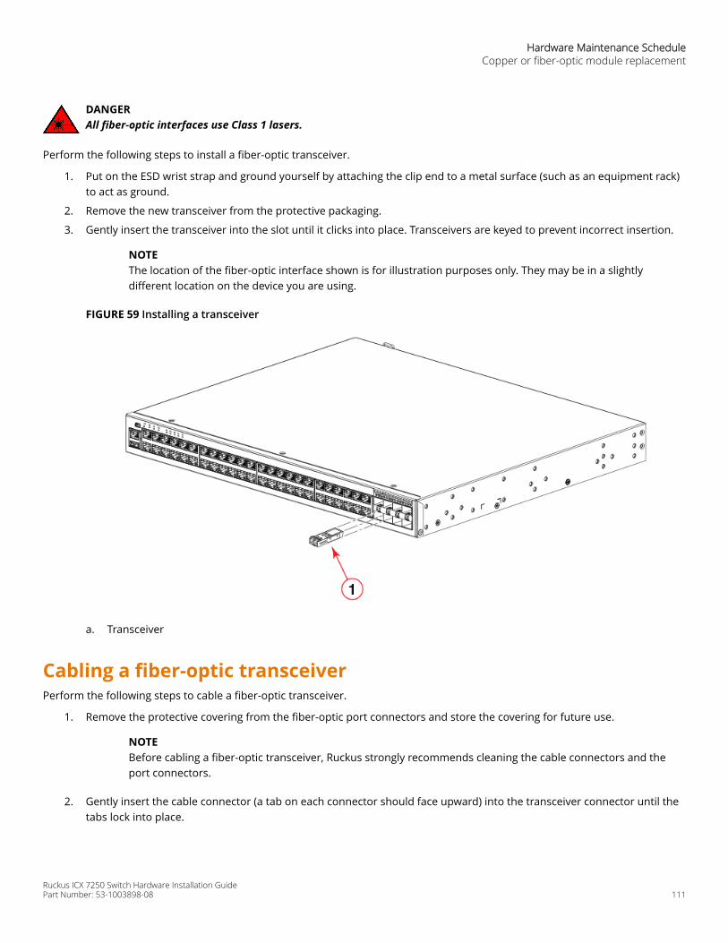
DANGERAll fiber-optic interfaces use Class 1 lasers.
Perform the following steps to install a fiber-optic transceiver.
1. Put on the ESD wrist strap and ground yourself by attaching the clip end to a metal surface (such as an equipment rack)to act as ground.
2. Remove the new transceiver from the protective packaging.
3. Gently insert the transceiver into the slot until it clicks into place. Transceivers are keyed to prevent incorrect insertion.
NOTEThe location of the fiber-optic interface shown is for illustration purposes only. They may be in a slightlydifferent location on the device you are using.
FIGURE 59 Installing a transceiver
a. Transceiver
Cabling a fiber-optic transceiverPerform the following steps to cable a fiber-optic transceiver.
1. Remove the protective covering from the fiber-optic port connectors and store the covering for future use.
NOTEBefore cabling a fiber-optic transceiver, Ruckus strongly recommends cleaning the cable connectors and theport connectors.
2. Gently insert the cable connector (a tab on each connector should face upward) into the transceiver connector until thetabs lock into place.
Hardware Maintenance ScheduleCopper or fiber-optic module replacement
Ruckus ICX 7250 Switch Hardware Installation GuidePart Number: 53-1003898-08 111

3. Observe the link and active LEDs to determine if the network connections are functioning properly. For moreinformation about the LED indicators, refer to Observing LEDs on page 92.
Cleaning the fiber-optic connectorsTo avoid problems with the connection between the fiber-optic transceiver (SFP or SFP+) and the fiber cable connectors, Ruckusstrongly recommends cleaning both connectors each time you disconnect and reconnect them. Dust can accumulate in theconnectors and cause problems, such as reducing the optic launch power.
To clean the fiber cable connectors, Ruckus recommends using a fiber-optic reel-type cleaner. When not using an SFP or SFP+connector, make sure to keep the protective covering in place.
Cabling a fiber-optic transceiverPerform the following steps to cable a fiber-optic transceiver.
1. Remove the protective covering from the fiber-optic port connectors and store the covering for future use.
NOTEBefore cabling a fiber-optic transceiver, Ruckus strongly recommends cleaning the cable connectors and theport connectors.
2. Gently insert the cable connector (a tab on each connector should face upward) into the transceiver connector until thetabs lock into place.
3. Observe the link and active LEDs to determine if the network connections are functioning properly. For moreinformation about the LED indicators, refer to Observing LEDs on page 92.
Hardware Maintenance ScheduleCabling a fiber-optic transceiver
Ruckus ICX 7250 Switch Hardware Installation Guide112 Part Number: 53-1003898-08

Troubleshooting• Diagnosing switch indicators................................................................................................................................... 113
Diagnosing switch indicatorsThe following table lists the troubleshooting steps you can perform based on device LED status.
TABLE 19 Troubleshooting the device based on LED status Symptom Action
Power LED is Off • Check if internal power supply is disconnected.• Check connections between the device, the power cord, and
the wall outlet.• Contact Technical Support.
Power LED is Amber Internal power supply has failed. Contact Technical Support.
Diag LED is Amber • The device self test has detected a fault.• Power cycle the device to try and clear the condition. If the
condition persists, contact Technical Support.
Link LED is Off • Verify that the device and attached device are powered on.• Be sure the cable is plugged into both the device and the
corresponding device.• Verify that the proper cable type is used and its length does
not exceed specified limits.• Check the adapter on the attached device and cable
connections for possible defects. Replace the defectiveadapter or cable if necessary.
InstallationVerify that all system components have been properly installed. If one or more components appear to be malfunctioning (suchas the power cord or network cabling), test them in an alternate environment where you are sure that all the other componentsare functioning properly.
Power and cooling problemsIf the power indicator does not turn on when the power cord is plugged in, you may have a problem with the power outlet,power cord, or internal power supply. However, if the unit powers off after running for a while, check for loose powerconnections, power losses or surges at the power outlet, and use the show chassis command to verify that the temperature isbelow the shutdown threshold. If you still cannot isolate the problem, then the internal power supply may be defective. In thiscase, contact Ruckus Technical Support for assistance.
Ruckus ICX 7250 Switch Hardware Installation GuidePart Number: 53-1003898-08 113

In-band accessYou can access the management agent in the device from anywhere within the attached network using Telnet or other networkmanagement software. However, you must first configure the device with a valid IP address, subnet mask, and default gateway. Ifyou have trouble establishing a link to the management agent, check to see if you have a valid network connection. Then verifythat you entered the correct IP address. Also, be sure the port through which you are connecting to the device has not beendisabled. If it has not been disabled, then check the network cabling that runs between your remote location and the device.
Troubleshooting Diagnosing switch indicators
Ruckus ICX 7250 Switch Hardware Installation Guide114 Part Number: 53-1003898-08

Regulatory Statements• CE statement..............................................................................................................................................................115• China ROHS................................................................................................................................................................115• BSMI statement (Taiwan)..........................................................................................................................................115• Canadian requirements............................................................................................................................................117• China CCC statement................................................................................................................................................ 118• Europe and Australia (CISPR 32 Class A Warning).................................................................................................118• FCC warning (US only)...............................................................................................................................................119• Germany statement.................................................................................................................................................. 119• KCC statement (Republic of Korea)......................................................................................................................... 119• VCCI statement.......................................................................................................................................................... 119
CE statementATTENTIONThis is a Class A product. In a domestic environment, this product might cause radio interference, and the user might berequired to take corrective measures.
The standards compliance label on this device contains the CE mark which indicates that this system conforms to the provisionsof the following European Council directives, laws, and standards:
• Electromagnetic Compatibility (EMC) Directive 2014/30/EU
• Low Voltage Directive (LVD) 2014/35/EU
• EN 55032/EN 55024 (European Immunity Requirements)
– EN61000-3-2/JEIDA (European and Japanese Harmonics Spec)– EN61000-3-3
China ROHSRefer to the latest revision of the China ROHS document (P/N 53‐1000428‐xx) which ships with the product.
BSMI statement (Taiwan)
Warning:
This is Class A product. In a domestic environment this product may cause radio interference in which case the user may berequired to take adequate measures.
Ruckus ICX 7250 Switch Hardware Installation GuidePart Number: 53-1003898-08 115
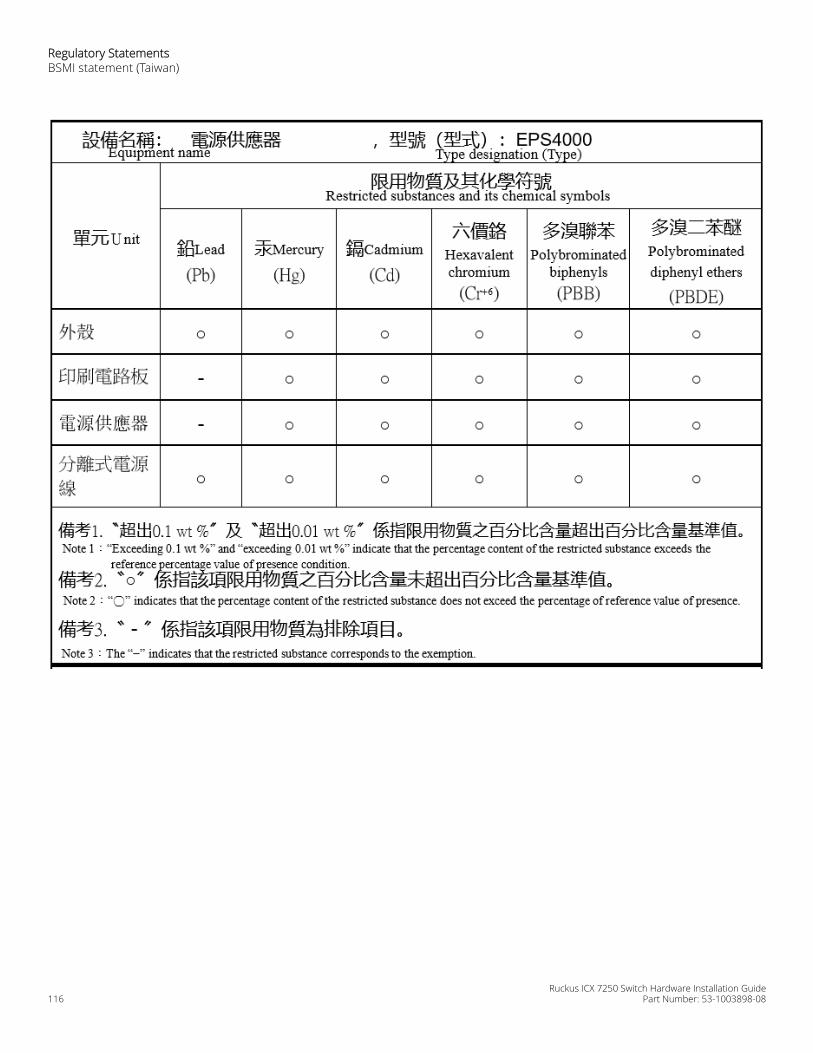
Regulatory StatementsBSMI statement (Taiwan)
Ruckus ICX 7250 Switch Hardware Installation Guide116 Part Number: 53-1003898-08

Canadian requirementsThis Class A digital apparatus meets all requirements of the Canadian Interference-Causing Equipment Regulations, ICES-003Class A.
Cet appareil numérique de la classe A est conforme à la norme NMB-003 du Canada.
Regulatory StatementsCanadian requirements
Ruckus ICX 7250 Switch Hardware Installation GuidePart Number: 53-1003898-08 117

China CCC statement
Europe and Australia (CISPR 32 Class A Warning)This is a Class A product. In a domestic environment this product may cause radio interference in which case the user may berequired to take adequate measures.
Regulatory StatementsChina CCC statement
Ruckus ICX 7250 Switch Hardware Installation Guide118 Part Number: 53-1003898-08

FCC warning (US only)This equipment has been tested and complies with the limits for a Class A computing device pursuant to Part 15 of the FCCRules. These limits are designed to provide reasonable protection against harmful interference when the equipment is operatedin a commercial environment.
This equipment generates, uses, and can radiate radio frequency energy, and if not installed and used in accordance with theinstruction manual, might cause harmful interference to radio communications. Operation of this equipment in a residential areais likely to cause harmful interference, in which case the user will be required to correct the interference at the user’s ownexpense.
Germany statementMachine noise information regulation - 3. GPSGV, the highest sound pressure level value is 70.0 dB(A) in accordance with EN ISO7779.
Maschinenlärminformations-Verordnung - 3. GPSGV, der höchste Schalldruckpegel beträgt 70.0 dB(A) gemäss EN ISO 7779.
KCC statement (Republic of Korea)
Class A device (Broadcasting Communication Device for Office Use): This device obtained EMC registration for office use (Class A),and may be used in places other than home. Sellers and/or users need to take note of this.
VCCI statement
This is a Class A product based on the standard of the Voluntary Control Council for Interference by Information TechnologyEquipment (VCCI). If this equipment is used in a domestic environment, radio disturbance might arise. When such trouble occurs,the user might be required to take corrective actions.
Regulatory StatementsVCCI statement
Ruckus ICX 7250 Switch Hardware Installation GuidePart Number: 53-1003898-08 119

Ruckus ICX 7250 Switch Hardware Installation Guide120 Part Number: 53-1003898-08

Cautions and Danger Notices• Cautions......................................................................................................................................................................121• Danger Notices.......................................................................................................................................................... 123
CautionsA Caution statement alerts you to situations that can be potentially hazardous to you or cause damage to hardware, firmware,software, or data.
Ein Vorsichthinweis warnt Sie vor potenziellen Personengefahren oder Beschädigung der Hardware, Firmware, Software oderauch vor einem möglichen Datenverlust
Un message de mise en garde vous alerte sur des situations pouvant présenter un risque potentiel de dommages corporels oude dommages matériels, logiciels ou de perte de données.
Un mensaje de precaución le alerta de situaciones que pueden resultar peligrosas para usted o causar daños en el hardware, elfirmware, el software o los datos.
General cautionsCAUTIONDo not install the device in an environment where the operating ambient temperature might exceed 50°C(122°F).
VORSICHT Das Gerät darf nicht in einer Umgebung mit einer Umgebungsbetriebstemperatur von über 50°C (122°F) installiertwerden.
MISE EN GARDE N'installez pas le dispositif dans un environnement où la température d'exploitation ambiante risque de dépasser50°C (122°F).
PRECAUCIÓN No instale el instrumento en un entorno en el que la temperatura ambiente de operación pueda exceder los 50°C(122°F).
CAUTIONMake sure the airflow around the front, and back of the device is not restricted.
VORSICHT Stellen Sie sicher, dass an der Vorderseite, den Seiten und an der Rückseite der Luftstrom nicht behindert wird.
MISE EN GARDE Vérifiez que rien ne restreint la circulation d'air devant, derrière et sur les côtés du dispositif et qu'elle peut se fairelibrement.
PRECAUCIÓN Asegúrese de que el flujo de aire en las inmediaciones de las partes anterior, laterales y posterior del instrumento noesté restringido.
CAUTIONEnsure that adequate ventilation is provided for the system. A 3 cm clearance is recommended above thedevice and 8 cm clearance is recommended on each side.
VORSICHT Stellen Sie sicher, dass das System ausreichend belüftet wird. Über dem Gerät wird 3 cm Freiraum, auf beiden Seitenjeweils 8 cm Freiraum empfohlen.
MISE EN GARDE Assurez-vous que le circuit est correctement ventilé. Il est recommandé de conserver un espace de 3 cm au-dessus dudispositif, et de 8 cm sur chaque côté.
Ruckus ICX 7250 Switch Hardware Installation GuidePart Number: 53-1003898-08 121
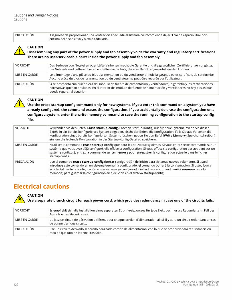
PRECAUCIÓN Asegúrese de proporcionar una ventilación adecuada al sistema. Se recomienda dejar 3 cm de espacio libre porencima del dispositivo y 8 cm a cada lado.
CAUTIONDisassembling any part of the power supply and fan assembly voids the warranty and regulatory certifications.There are no user-serviceable parts inside the power supply and fan assembly.
VORSICHT Das Zerlegen von Netzteilen oder Lüftereinheiten macht die Garantie und die gesetzlichen Zertifizierungen ungültig.Die Netzteile und Lüftereinheiten enthalten keine Teile, die vom Benutzer gewartet werden können.
MISE EN GARDE Le démontage d'une pièce du bloc d'alimentation ou du ventilateur annule la garantie et les certificats de conformité.Aucune pièce du bloc de l'alimentation ou du ventilateur ne peut être réparée par l'utilisateur.
PRECAUCIÓN Si se desmonta cualquier pieza del módulo de fuente de alimentación y ventiladores, la garantía y las certificacionesnormativas quedan anuladas. En el interior del módulo de fuente de alimentación y ventiladores no hay piezas quepueda reparar el usuario.
CAUTIONUse the erase startup-config command only for new systems. If you enter this command on a system you havealready configured, the command erases the configuration. If you accidentally do erase the configuration on aconfigured system, enter the write memory command to save the running configuration to the startup-configfile.
VORSICHT Verwenden Sie den Befehl Erase startup-config (Löschen Startup-Konfig) nur für neue Systeme. Wenn Sie diesenBefehl in ein bereits konfiguriertes System eingeben, löscht der Befehl die Konfiguration. Falls Sie aus Versehen dieKonfiguration eines bereits konfigurierten Systems löschen, geben Sie den BefehlWrite Memory (Speicher schreiben)ein, um die laufende Konfiguration in der Startup-Konfig-Datei zu speichern.
MISE EN GARDE N'utilisez la commande erase startup-config que pour les nouveaux systèmes. Si vous entrez cette commande sur unsystème que vous avez déjà configuré, elle efface la configuration. Si vous effacez la configuration par accident sur unsystème configuré, entrez la commande write memory pour enregistrer la configuration actuelle dans le fichierstartup-config.
PRECAUCIÓN Use el comando erase startup-config (borrar configuración de inicio) para sistemas nuevos solamente. Si ustedintroduce este comando en un sistema que ya ha configurado, el comando borrará la configuración. Si usted borraaccidentalmente la configuración en un sistema ya configurado, introduzca el comando write memory (escribirmemoria) para guardar la configuración en ejecución en el archivo startup-config.
Electrical cautionsCAUTIONUse a separate branch circuit for each power cord, which provides redundancy in case one of the circuits fails.
VORSICHT Es empfiehlt sich die Installation eines separaten Stromkreiszweiges für jede Elektroschnur als Redundanz im Fall desAusfalls eines Stromkreises.
MISE EN GARDE Utilisez un circuit de dérivation différent pour chaque cordon d’alimentation ainsi, il y aura un circuit redondant en casde panne d’un des circuits.
PRECAUCIÓN Use un circuito derivado separado para cada cordón de alimentación, con lo que se proporcionará redundancia encaso de que uno de los circuitos falle.
Cautions and Danger NoticesCautions
Ruckus ICX 7250 Switch Hardware Installation Guide122 Part Number: 53-1003898-08
CAUTIONEnsure that the device does not overload the power circuits, wiring, and over-current protection. To determinethe possibility of overloading the supply circuits, add the ampere (amp) ratings of all devices installed on thesame circuit as the device. Compare this total with the rating limit for the circuit. The maximum ampere ratingsare usually printed on the devices near the input power connectors.
VORSICHT Stromkreise, Verdrahtung und Überlastschutz dürfen nicht durch das Gerät überbelastet werden. Addieren Sie dieNennstromleistung (in Ampere) aller Geräte, die am selben Stromkreis wie das Gerät installiert sind. Somit können Siefeststellen, ob die Gefahr einer Überbelastung der Versorgungsstromkreise vorliegt. Vergleichen Sie diese Summe mitder Nennstromgrenze des Stromkreises. Die Höchstnennströme (in Ampere) stehen normalerweise auf derGeräterückseite neben den Eingangsstromanschlüssen.
MISE EN GARDE Assurez-vous que le dispositif ne risque pas de surcharger les circuits d'alimentation, le câblage et la protection desurintensité. Pour déterminer le risque de surcharge des circuits d'alimentation, additionnez l'intensité nominale(ampères) de tous les dispositifs installés sur le même circuit que le dispositif en question. Comparez alors ce totalavec la limite de charge du circuit. L'intensité nominale maximum en ampères est généralement imprimée sur chaquedispositif près des connecteurs d'entrée d'alimentation.
PRECAUCIÓN Verifique que el instrumento no sobrecargue los circuitos de corriente, el cableado y la protección para sobrecargas.Para determinar la posibilidad de sobrecarga en los circuitos de suministros, añada las capacidades nominales decorriente (amp) de todos los instrumentos instalados en el mismo circuito que el instrumento. Compare esta sumacon el límite nominal para el circuito. Las capacidades nominales de corriente máximas están generalmente impresasen los instrumentos, cerca de los conectores de corriente de entrada.
CAUTIONBefore plugging a cable into any port, be sure to discharge the voltage stored on the cable by touching theelectrical contacts to ground surface.
VORSICHT Bevor Sie ein Kabel in einen Anschluss einstecken, entladen Sie jegliche im Kabel vorhandene elektrische Spannung,indem Sie mit den elektrischen Kontakten eine geerdete Oberfläche berühren.
MISE EN GARDE Avant de brancher un câble à un port, assurez-vous de décharger la tension du câble en reliant les contacts électriquesà la terre.
PRECAUCIÓN Antes de conectar un cable en cualquier puerto, asegúrese de descargar la tensión acumulada en el cable tocando lasuperficie de conexión a tierra con los contactos eléctricos.
CAUTIONDisassembling any part of the power supply and fan assembly voids the warranty and regulatory certifications.There are no user-serviceable parts inside the power supply and fan assembly.
VORSICHT Das Zerlegen von Netzteilen oder Lüftereinheiten macht die Garantie und die gesetzlichen Zertifizierungen ungültig.Die Netzteile und Lüftereinheiten enthalten keine Teile, die vom Benutzer gewartet werden können.
MISE EN GARDE Le démontage d'une pièce du bloc d'alimentation ou du ventilateur annule la garantie et les certificats de conformité.Aucune pièce du bloc de l'alimentation ou du ventilateur ne peut être réparée par l'utilisateur.
PRECAUCIÓN Si se desmonta cualquier pieza del módulo de fuente de alimentación y ventiladores, la garantía y las certificacionesnormativas quedan anuladas. En el interior del módulo de fuente de alimentación y ventiladores no hay piezas quepueda reparar el usuario.
Danger NoticesA Danger statement indicates conditions or situations that can be potentially lethal or extremely hazardous to you. Safety labelsare also attached directly to products to warn of these conditions or situations.
Ein Gefahrenhinweis warnt vor Bedingungen oder Situationen die tödlich sein können oder Sie extrem gefährden können.Sicherheitsetiketten sind direkt auf den jeweiligen Produkten angebracht um vor diesen Bedingungen und Situationen zuwarnen.
Cautions and Danger NoticesDanger Notices
Ruckus ICX 7250 Switch Hardware Installation GuidePart Number: 53-1003898-08 123

Un énoncé de danger indique des conditions ou des situations potentiellement mortelles ou extrêmement dangereuses. Desétiquettes de sécurité sont posées directement sur le produit et vous avertissent de ces conditions ou situations.
Una advertencia de peligro indica condiciones o situaciones que pueden resultar potencialmente letales o extremadamentepeligrosas. También habrá etiquetas de seguridad pegadas directamente sobre los productos para advertir de estas condicioneso situaciones.
General dangersDANGERThe procedures in this manual are for qualified service personnel.
GEFAHR Die Vorgehensweisen in diesem Handbuch sind für qualifiziertes Servicepersonal bestimmt.
DANGER Les procédures décrites dans ce manuel doivent être effectuées par un personnel de maintenance qualifié.
PELIGRO Los procedimientos de este manual deben llevarlos a cabo técnicos cualificados.
DANGERBe careful not to accidently insert your fingers into the fan tray while removing it from the chassis. The fan may stillbe spinning at a high speed.
GEFAHR Die Finger dürfen nicht versehentlich in das Ventilatorblech gesteckt werden, wenn dieses vom Gehäuse abgenommenwird. Der Ventilator kann sich unter Umständen noch mit hoher Geschwindigkeit drehen.
DANGER Faites attention de ne pas insérer vos doigts accidentellement dans le boîtier du ventilateur lorsque vous le retirez duchâssis. Il est possible que le ventilateur tourne encore à grande vitesse.
PELIGRO Procure no insertar los dedos accidentalmente en la bandeja del ventilador cuando esté desmontando el chasis. Elventilador podría estar girando a gran velocidad.
DANGERThis equipment is suitable for mounting on concrete or other noncombustible surfaces only.
GEFAHR Dieses Gerät darf nur auf Beton oder auf andere, nicht brennbare Flächen installiert werden.
DANGER Cet équipement est adapté à être monté sur du béton ou seulement sur d'autres surfaces non combustibles.
PELIGRO Este equipo es apto para el montaje solamente en superficies de concreto ó en otro tipos de superficies nocombustibles.
Electrical dangersDANGERBefore beginning the installation, see the precautions in “Power precautions.”
GEFAHR Vor der Installation siehe Vorsichtsmaßnahmen unter “Power Precautions” (Vorsichtsmaßnahmen in Bezug aufelektrische Ablagen).
DANGER Avant de commencer l'installation, consultez les précautions décrites dans “Power Precautions” (Précautions quant àl'alimentation).
PELIGRO Antes de comenzar la instalación, consulte las precauciones en la sección “Power Precautions” (Precauciones sobrecorriente).
Cautions and Danger NoticesDanger Notices
Ruckus ICX 7250 Switch Hardware Installation Guide124 Part Number: 53-1003898-08
DANGERDisconnect the power cord from all power sources to completely remove power from the device.
GEFAHR Ziehen Sie das Stromkabel aus allen Stromquellen, um sicherzustellen, dass dem Gerät kein Strom zugeführt wird.
DANGER Débranchez le cordon d'alimentation de toutes les sources d'alimentation pour couper complètement l'alimentationdu dispositif.
PELIGRO Para desconectar completamente la corriente del instrumento, desconecte el cordón de corriente de todas las fuentesde corriente.
DANGERIf the installation requires a different power cord than the one supplied with the device, make sure you use a powercord displaying the mark of the safety agency that defines the regulations for power cords in your country. The markis your assurance that the power cord can be used safely with the device.
GEFAHR Falls für die Installation ein anderes Stromkabel erforderlich ist (wenn das mit dem Gerät gelieferte Kabel nicht passt),müssen Sie sicherstellen, dass Sie ein Stromkabel mit dem Siegel einer Sicherheitsbehörde verwenden, die für dieZertifizierung von Stromkabeln in Ihrem Land zuständig ist. Das Siegel ist Ihre Garantie, dass das Stromkabel sicher mitIhrem Gerät verwendet werden kann.
DANGER Si l'installation nécessite un cordon d'alimentation autre que celui fourni avec le dispositif, assurez-vous d'utiliser uncordon d'alimentation portant la marque de l'organisation responsable de la sécurité qui définit les normes etrégulations pour les cordons d'alimentation dans votre pays. Cette marque vous assure que vous pouvez utiliser lecordon d'alimentation avec le dispositif en toute sécurité.
PELIGRO Si la instalación requiere un cordón de corriente distinto al que se ha suministrado con el instrumento, verifique queusa un cordón de corriente que venga con la marca de la agencia de seguridad que defina las regulaciones paracordones de corriente en su país. Esta marca será su garantía de que el cordón de corriente puede ser utilizado conseguridad con el instrumento.
DANGERFor safety reasons, the ESD wrist strap should contain a series 1 megaohm resistor.
GEFAHR Aus Sicherheitsgründen sollte ein EGB-Armband zum Schutz von elektronischen gefährdeten Bauelementen mit einem1 Megaohm-Reihenwiderstand ausgestattet sein.
DANGER Pour des raisons de sécurité, la dragonne ESD doit contenir une résistance de série 1 méga ohm.
PELIGRO Por razones de seguridad, la correa de muñeca ESD deberá contener un resistor en serie de 1 mega ohmio.
Dangers related to equipment weightDANGERMake sure the rack housing the device is adequately secured to prevent it from becoming unstable or falling over.
GEFAHR Stellen Sie sicher, dass das Gestell für die Unterbringung des Geräts auf angemessene Weise gesichert ist, so dass dasGestell oder der Schrank nicht wackeln oder umfallen kann.
DANGER Vérifiez que le bâti abritant le dispositif est bien fixé afin qu'il ne devienne pas instable ou qu'il ne risque pas detomber.
PELIGRO Verifique que el bastidor que alberga el instrumento está asegurado correctamente para evitar que pueda hacerseinestable o que caiga.
Cautions and Danger NoticesDanger Notices
Ruckus ICX 7250 Switch Hardware Installation GuidePart Number: 53-1003898-08 125
DANGERMount the devices you install in a rack as low as possible. Place the heaviest device at the bottom and progressivelyplace lighter devices above.
GEFAHR Montieren Sie die Geräte im Gestell so tief wie möglich. Platzieren Sie das schwerste Gerät ganz unten, währendleichtere Geräte je nach Gewicht (je schwerer desto tiefer) darüber untergebracht werden.
DANGER Montez les dispositifs que vous installez dans un bâti aussi bas que possible. Placez le dispositif le plus lourd en bas etle plus léger en haut, en plaçant tous les dispositifs progressivement de bas en haut du plus lourd au plus léger.
PELIGRO Monte los instrumentos que instale en un bastidor lo más bajos posible. Ponga el instrumento más pesado en la parteinferior y los instrumentos progresivamente más livianos más arriba.
Laser dangersDANGERAll fiber-optic interfaces use Class 1 lasers.
GEFAHR Alle Glasfaser-Schnittstellen verwenden Laser der Klasse 1.
DANGER Toutes les interfaces en fibre optique utilisent des lasers de classe 1.
PELIGRO Todas las interfaces de fibra óptica utilizan láser de clase 1.
Cautions and Danger NoticesDanger Notices
Ruckus ICX 7250 Switch Hardware Installation Guide126 Part Number: 53-1003898-08

© 2019 ARRIS Enterprises LLC. All rights reserved.Ruckus Wireless, Inc., a wholly owned subsidiary of ARRIS International plc.350 West Java Dr., Sunnyvale, CA 94089 USAwww.ruckuswireless.com


