The content of this service document is the subject of intellectual property rights reserved by DNV GL AS ("DNV GL"). The user accepts that it is prohibited by anyone else but DNV GL and/or its licensees to offer and/or perform classification, certification and/or verification services, including the issuance of certificates and/or declarations of conformity, wholly or partly, on the basis of and/or pursuant to this document whether free of charge or chargeable, without DNV GL's prior written consent. DNV GL is not responsible for the consequences arising from any use of this document by others. The electronic pdf version of this document, available free of charge from http://www.dnvgl.com, is the officially binding version. DNV GL AS RULES FOR CLASSIFICATION Ships Edition January 2017 Part 3 Hull Chapter 12 Openings and closing appliances
Transcript
The content of this service document is the subject of intellectual property rights reserved by DNV GL AS ("DNV GL"). The useraccepts that it is prohibited by anyone else but DNV GL and/or its licensees to offer and/or perform classification, certificationand/or verification services, including the issuance of certificates and/or declarations of conformity, wholly or partly, on thebasis of and/or pursuant to this document whether free of charge or chargeable, without DNV GL's prior written consent.DNV GL is not responsible for the consequences arising from any use of this document by others.
The electronic pdf version of this document, available free of chargefrom http://www.dnvgl.com, is the officially binding version.
DNV GL AS
RULES FOR CLASSIFICATION
Ships
Edition January 2017
Part 3 Hull
Chapter 12 Openings and closing appliances
FOREWORD
DNV GL rules for classification contain procedural and technical requirements related to obtainingand retaining a class certificate. The rules represent all requirements adopted by the Society asbasis for classification.
If any person suffers loss or damage which is proved to have been caused by any negligent act or omission of DNV GL, then DNV GL shallpay compensation to such person for his proved direct loss or damage. However, the compensation shall not exceed an amount equal to tentimes the fee charged for the service in question, provided that the maximum compensation shall never exceed USD 2 million.
In this provision "DNV GL" shall mean DNV GL AS, its direct and indirect owners as well as all its affiliates, subsidiaries, directors, officers,employees, agents and any other acting on behalf of DNV GL.
Part
3 C
hapt
er 1
2 Cha
nges
- c
urre
nt
Rules for classification: Ships — DNVGL-RU-SHIP Pt.3 Ch.12. Edition January 2017 Page 3Openings and closing appliances
DNV GL AS
CHANGES – CURRENT
This document supersedes the July 2016 edition.Changes in this document are highlighted in red colour. However, if the changes involve a whole chapter,section or sub-section, normally only the title will be in red colour.
Main changes January 2017, entering into force as from date ofpublication
• Sec.1 General— The text is revised to clarify the requirements and align with IACS.
• Sec.2 Access openings in freeboard deck and other exposed decks— The text is revised to clarify the requirements and align with IACS.
• Sec.3 Internal doors and hatches— The text is revised to clarify the requirements and align with IACS.
• Sec.5 Side, stern and bow doors - ramps— The requirements to shell doors are aligned with IACS.
• Sec.6 Windows, side scuttles and skylights— Sec.6 [5.2]: A minimum requirement is introduced for the adhesive bonding for windows.
Editorial correctionsIn addition to the above stated changes, editorial corrections may have been made.
Part
3 C
hapt
er 1
2 Con
tent
s
Rules for classification: Ships — DNVGL-RU-SHIP Pt.3 Ch.12. Edition January 2017 Page 4Openings and closing appliances
Section 2 Access openings in freeboard deck and other exposed decks................ 121 Access openings in freeboard and superstructure decks....................12
1.1 General..........................................................................................121.2 General securing arrangement..........................................................131.3 Securing arrangements for hatches in way of tanks.............................14
2 Service/access hatches..................................................................... 152.1 Application and definition.................................................................152.2 Materials........................................................................................152.3 Height of hatch coamings................................................................ 152.4 Scantling of hatch coamings and covers............................................ 152.5 Special requirements for type 'A' ships.............................................. 16
3 Small hatchways fitted on the exposed fore deck (UR S26)...............163.1 Application..................................................................................... 163.2 General..........................................................................................163.3 Strength........................................................................................ 163.4 Primary securing devices................................................................. 173.5 Requirement to primary securing......................................................173.6 Secondary securing devices............................................................. 19
4 Weathertight doors............................................................................194.1 General..........................................................................................194.2 Sill heights and arrangement........................................................... 204.3 Scantlings and structural arrangement.............................................. 21
Section 3 Internal doors and hatches................................................................... 221 Application.........................................................................................222 Securing and tightness arrangement.................................................22
Part
3 C
hapt
er 1
2 Con
tent
s
Rules for classification: Ships — DNVGL-RU-SHIP Pt.3 Ch.12. Edition January 2017 Page 5Openings and closing appliances
DNV GL AS
2.1 General..........................................................................................222.2 Securing arrangements for hatch- or ramp covers carrying deck cargo... 222.3 Sealing.......................................................................................... 22
3 Internal hatches/ramps.....................................................................233.1 Design loads.................................................................................. 233.2 Strength of hatch- and ramp cover................................................... 24
4 Watertight doors and hatches........................................................... 254.1 General..........................................................................................254.2 Operation.......................................................................................254.3 Strength........................................................................................ 25
Section 4 Cargo hatch covers - coamings and closing arrangements of cargohold of ships (UR S21A).......................................................................................28
2 Loads on hatch cover and coaming................................................... 312.1 Application..................................................................................... 312.2 Load case A: vertical and horizontal weather design load..................... 312.3 Load case B: cargo loads.................................................................342.4 Load case C: container loads........................................................... 352.5 Load case D: loads due to liquids in hold...........................................382.6 Load case E: loads due to elastic deformations of the ship's hull............38
3 Hatch cover strength criteria.............................................................383.1 Permissible stresses and deflections.................................................. 383.2 Local scantlings.............................................................................. 403.3 Strength calculation........................................................................ 443.4 Buckling strength of hatch cover structures........................................46
4 Details of hatch covers......................................................................464.1 Container foundations on hatch covers.............................................. 464.2 Weather tightness...........................................................................474.3 Packing..........................................................................................47
5 Hatch coaming design and strength criteria...................................... 485.1 General..........................................................................................485.2 Local net plate thickness of coamings............................................... 495.3 Net scantling of secondary stiffeners of coamings............................... 49
Part
3 C
hapt
er 1
2 Con
tent
s
Rules for classification: Ships — DNVGL-RU-SHIP Pt.3 Ch.12. Edition January 2017 Page 6Openings and closing appliances
DNV GL AS
5.4 Coaming stays................................................................................495.5 Further requirements for hatch coamings...........................................51
Section 5 Side, stern and bow doors - ramps....................................................... 581 Side and stern doors/ramps..............................................................58
1.1 Application..................................................................................... 581.2 General..........................................................................................581.3 Structural arrangement....................................................................591.4 Design loads at sea........................................................................ 591.5 Design loads in port........................................................................601.6 Plating........................................................................................... 601.7 Stiffeners....................................................................................... 611.8 Girders.......................................................................................... 611.9 Acceptance criteria for direct calculations...........................................621.10 Closing arrangement, general......................................................... 621.11 Closing arrangement, strength........................................................631.12 Closing arrangement, system for operation and indication/monitoring...........................................................................................63
2 Bow doors..........................................................................................652.1 Application and definitions............................................................... 652.2 Arrangement.................................................................................. 662.3 Materials........................................................................................662.4 Design loads.................................................................................. 672.5 Strength criteria............................................................................. 692.6 Structural arrangement....................................................................702.7 Plating........................................................................................... 702.8 Stiffeners....................................................................................... 712.9 Girders.......................................................................................... 712.10 Closing arrangement, general......................................................... 722.11 Closing arrangement, strength........................................................732.12 Closing arrangement, system for operation and indication andmonitoring...........................................................................................75
Section 6 Windows, side scuttles and skylights....................................................771 Application and general requirements............................................... 77
1.1 Application and general requirements................................................772 Definitions..........................................................................................77
Part
3 C
hapt
er 1
2 Con
tent
s
Rules for classification: Ships — DNVGL-RU-SHIP Pt.3 Ch.12. Edition January 2017 Page 7Openings and closing appliances
DNV GL AS
2.1 Definitions......................................................................................773 Arrangement and positioning............................................................ 78
3.1 Arrangement and positioning............................................................784 Glass thickness.................................................................................. 79
6 Testing requirements.........................................................................826.1 Introduction................................................................................... 826.2 Test arrangement............................................................................826.3 Test temperature for laminated glass................................................ 826.4 Hose testing...................................................................................82
Section 7 Tank access, ullage and ventilation openings........................................831 General.............................................................................................. 83
1.1 Introduction................................................................................... 832 Tank access hatchways..................................................................... 83
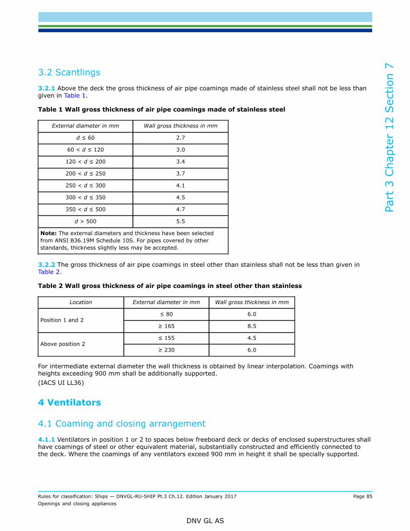
2.1 Scantlings...................................................................................... 833 Air pipes............................................................................................ 84
Section 8 Machinery space openings.....................................................................911 Machinery space openings.................................................................91
1.1 Openings....................................................................................... 912 Special requirements for type 'A' ships............................................. 91
2.1 Freeing port area............................................................................983 Location and protection of openings................................................100
3.1 Location and protection of openings................................................ 1004 Multiple wells...................................................................................1005 Free flow area................................................................................. 1006 Special requirements....................................................................... 101
6.1 Type 'A' ships............................................................................... 1016.2 Type 'B-100' and 'B-60' ships......................................................... 101
Rules for classification: Ships — DNVGL-RU-SHIP Pt.3 Ch.12. Edition January 2017 Page 9Openings and closing appliances
DNV GL AS
SECTION 1 GENERAL
1 ApplicationIn this chapter the requirements for the arrangement of openings and closing appliances have been collected.In general, the closing appliances shall have at least the strength corresponding to the required strength ofthat part of the hull in which they are fitted.
2 DefinitionDefinition of position 1 and position 2 is given in Ch.1 Sec.4 [3.2].
3 Documentation requirements
3.1 GeneralThe documents to be submitted are indicated in Ch.1 Sec.3.
3.2 Operating and maintenance manual3.2.1 GeneralShell doors, such as bow doors and inner doors, side doors an stern doors leading to RO/RO spaces or specialcategory spaces as defined in Ch.1 Sec.4, shall be provided with an operational maintenance manual (OMM)that shall have a content as described in [3.2.2].(IACS UR S8.8 and S9.7)
3.2.2 Required content for OMM
a) Main particulars and design drawings
— special safety precautions— details of vessel, class— equipment and design loading (for ramps)— key plan of equipment (doors and ramps)— manufacturer's recommended testing for equipment— description of equipment for
— bow doors— inner bow doors— bow ramp/doors— side doors— stern doors— central power pack— bridge panel— engine control room panel.
b) Service conditions
— limiting heel and trim of ship for loading/unloading— limiting heel and trim for door operations— doors/ramps operating instructions— doors/ramps emergency operating instructions.
Part
3 C
hapt
er 1
2 Sec
tion
1
Rules for classification: Ships — DNVGL-RU-SHIP Pt.3 Ch.12. Edition January 2017 Page 10Openings and closing appliances
DNV GL AS
c) Maintenance
— schedule and extent of maintenance— trouble-shooting— acceptance/rejection criteria, acceptable clearances— manufacturer's maintenance procedures.
d) Register of inspections, including:
— inspection of locking, securing and supporting devices— repairs and renewals.
3.2.3 The operating and maintenance manual shall be submitted for approval with respect to the items listedabove being contained in the manual. In addition, the inclusion of the necessary information with regard toinspections, trouble-shooting and acceptance/rejection criteria in the maintenance part shall be verified.
Guidance note 1:It is recommended that recorded inspections of the door supporting and securing devices are carried out by the ship's staff atmonthly intervals or following incidents that could result in damage, including heavy weather or contact in the region of the shelldoors.Any damage recorded during such inspections should be reported. This should also be stated in the operating and maintenancemanual.
---e-n-d---o-f---g-u-i-d-a-n-c-e---n-o-t-e---
Guidance note 2:Reference is made to the safety management system described in the ISM Code.
---e-n-d---o-f---g-u-i-d-a-n-c-e---n-o-t-e---
3.2.4 On board documentationThe operation and maintenance manuals for the shell doors shall be provided on board.
3.3 Testing3.3.1 Function testingAll weathertight/watertight doors and hatch covers shall be function tested.
3.3.2 Container shipsFor ships exclusively intended for the carriage of containers in the cargo holds, for which an exemption tothe ICLL, Reg.16 (see Sec.4) has been granted by the flag administration, and which complies with therequirements given in Sec.4 [4.3.3] and Sec.4 [6.1.6], the required testing for weather tightness given inPt.2 Ch.4 Sec.2 may be dispensed with.If non-weathertight hatch covers are fitted, this will be noted in the appendix to classification certificate withthe implication that hose testing for weather tightness in accordance with Pt.2 Ch.4 Sec.2 will not be carriedout.
3.3.3 Damage conditionDoors and hatch covers which become immersed by an equilibrium or an intermediate water plane in adamaged condition shall be subjected to a hydrostatic pressure test. The head of water used for the pressuretest shall correspond at least to the head, measured from the lower edge of the door opening, at the locationin which the door is fitted in the vessel, to the most unfavourable damage waterplane. The acceptancecriteria for the test is no leakage.For large doors, above 6 m2, structural analysis may be accepted in lieu of pressure testing. Where suchdoors utilise gasket seals, a prototype pressure test of the gasket seal shall be carried out to confirm thatthe compression of the gasket material is capable of accommodating maximum deflection, revealed bythe structural analysis. After installation of such door or hatch, the initial gasket compression shall bedocumented.
Part
3 C
hapt
er 1
2 Sec
tion
1
Rules for classification: Ships — DNVGL-RU-SHIP Pt.3 Ch.12. Edition January 2017 Page 11Openings and closing appliances
DNV GL AS
Guidance note:Where testing of individual doors or hatches are not feasible, reference is made to SOLAS Ch.II-1 Reg.16/2.
---e-n-d---o-f---g-u-i-d-a-n-c-e---n-o-t-e---
3.4 Certification requirementsThe components to be certified are indicated in Ch.1 Sec.3 [3.1].
Part
3 C
hapt
er 1
2 Sec
tion
2
Rules for classification: Ships — DNVGL-RU-SHIP Pt.3 Ch.12. Edition January 2017 Page 12Openings and closing appliances
DNV GL AS
SECTION 2 ACCESS OPENINGS IN FREEBOARD DECK AND OTHEREXPOSED DECKSSymbols
For symbols not defined in this section, refer to Ch.1 Sec.4.
Standard tier height is defined in Ch.1 Sec.4 [3.3.1].
αp = correction factor for the panel aspect ratio to be taken as follows but not to be taken greater than1.0:
a = length of plate panel, in mm, as defined in Ch.3 Sec.7 [2.1.1]b = breadth of plate panel, in mm, as defined in Ch.3 Sec.7 [2.1.1]P = design pressure for the considered design load set, see Ch.6 Sec.2 [2], calculated at the load
calculation point defined in Ch.3 Sec.7 [2.2], in kN/m2
ℓbdg = effective bending span, in m, as defined in Ch.3 Sec.7 [1.1.2].
1 Access openings in freeboard and superstructure decks
1.1 General
1.1.1 Manholes and flush scuttles in position 1 or 2 or within superstructures other than enclosedsuperstructures shall be closed by substantial covers capable of being made watertight. Unless secured byclosely spaced bolts, the covers shall be permanently attached.(ICLL Reg.18)
1.1.2 Openings in freeboard decks other than hatchways, machinery space openings, manholes and flushscuttles shall be protected by an enclosed superstructure, or by a deckhouse or companionway of equivalentstrength and weathertightness. Any such opening in an exposed superstructure deck or in the top of adeckhouse on the freeboard deck which gives access to a space below the freeboard deck or a space withinan enclosed superstructure shall be protected by an efficient deckhouse or companionway. Doorways in suchdeckhouses or companionways shall be fitted with doors complying with the requirements given in [4.1.1]and [4.2.1].(ICLL Reg.18)
1.1.3 The height above the deck of sills to the doorways in companionways shall be at least;
— 600 mm in position 1— 380 mm in position 2.
(ICLL Reg.18)
1.1.4 Regarding the requirement for protecting openings in superstructures, as described in [1.1.2], it isconsidered that openings in the top of a deckhouse on a raised quarterdeck having a height equal to orgreater than a standard height raised quarterdeck shall be provided with an acceptable means of closing butneed not be protected by an efficient deckhouse or companionway as defined in the regulation provided theheight of the deckhouse is at least the height of a full superstructure. Openings in the top of the deck houseon a deck house of less than a standard superstructure height may be treated in a similar manner.(ICLL Reg.18)
Part
3 C
hapt
er 1
2 Sec
tion
2
Rules for classification: Ships — DNVGL-RU-SHIP Pt.3 Ch.12. Edition January 2017 Page 13Openings and closing appliances
DNV GL AS
1.1.5 Only those doorways in deckhouses leading to or giving access to companionways leading below, needto be fitted with doors in accordance with [4.1.1].
1.1.6 Alternatively, if stairways within a deckhouse are enclosed within properly constructed companionwaysfitted with doors complying with [4.1.1], the external doors need not be weathertight.(ICLL Reg.18)
1.1.7 Where an opening in a superstructure deck or in the top of a deckhouse on the freeboard deck whichgives access to a space below the freeboard deck or to a space within an enclosed superstructure is protectedby a deckhouse, then it is considered that only those side scuttles fitted in spaces which give direct accessto an open stairway need be fitted with deadlights in accordance with Sec.6 [3.1]. A cabin is considered toprovide adequate protection against the minimal amount of water which will enter through a broken sidescuttle glass fitted on the second tier.In the application of [1.1.1] and [1.1.2] it is understood that:
— where access is provided from the deck above as an alternative to access from the freeboard then theheight of sills into a bridge or poop shall be 380 mm. The same consideration shall apply to deckhouses onthe freeboard deck
— where access is not provided from above the height of the sills to doorways in a poop bridge or deckhouseon the freeboard deck shall be 600 mm
— where the closing appliances of access openings in superstructures and deckhouses are not in accordancewith [1.1.1], interior deck openings shall be considered exposed, i.e. situated in the open deck.
(IACS UI LL8)
1.2 General securing arrangement
1.2.1 Hatch covers on exposed decks shall be weathertight.
1.2.2 Securing arrangements and stiffening of hatch cover edges shall be such that weather tightness can bemaintained in any sea condition. At least one securing device shall be fitted at each side.Circular hole hinges are considered equivalent to securing devices.Butterfly nuts, cleats, central locking devices or hinges are considered securing devices.
1.2.3 The sealing shall be obtained by a continuous gasket of relatively soft elastic material compressedto achieve the necessary weathertightness. This shall be designed to allow a metal-to-metal contact at adesign compression and to prevent overcompression of the gasket. The metal-to-metal contact points shallbe preferably close to the securing devices.Coamings and steel parts of hatch covers in contact with gaskets shall have no sharp edges.
1.2.4 Hatches of special design will be considered on a case-by-case basis.
1.2.5 Ordinary packed hatch covers shall be secured to the coaming by a net bolt area, in cm2, for each boltnot less than:
A = 1.4 a ke
where:
a = spacing of bolts in mke = (235/ReH)e
ReH = minimum upper yield stress in N/mm2, not to be taken greater than 70% of the ultimate tensilestrength
Part
3 C
hapt
er 1
2 Sec
tion
2
Rules for classification: Ships — DNVGL-RU-SHIP Pt.3 Ch.12. Edition January 2017 Page 14Openings and closing appliances
DNV GL AS
e = 0.75 for ReH > 235= 1.0 for ReH ≤ 235
1.2.6 The net bolt diameter shall not be less than 19 mm for hatchways exceeding 5 m2 in area.
1.2.7 Between cover and coaming and at cross-joints, a packing line pressure sufficient to obtain weathertightness shall be maintained by a bolt area as given in [1.2.5] above.
1.2.8 For packing line pressures exceeding 5 N/mm, the area shall be increased accordingly. The packing linepressure shall be specified.
1.2.9 Closing appliances of covers to hatches on exposed decks (position 1 and 2) where reduced coamingheights are accepted (see [2.3.2]) will be specially considered.In this case each cover element shall be equipped with at least 2 securing devices along each side and themaximum distance shall not exceed amax = 2.5 m.
1.3 Securing arrangements for hatches in way of tanks
1.3.1 In addition to requirements given in [1.2], for hatches in way of tanks requirements in [1.3.2] to[1.3.4] shall be fulfilled.
1.3.2 Hatch covers fitted in way of tanks shall be watertight.
1.3.3 The net securing bolt area, in cm2, for each bolt shall not be less than:
A = 0.08 a ke (0.5 ℓ Pin + pℓ)
where:
a = spacing of bolts in mℓ = span in m of hatch cover girder or stiffener perpendicular to coaming, if any, or distance from cover
edge to the first parallel stiffenerPin = applicable internal pressure due to liquids shall be calculated according to Ch.4 Sec.6 [1]:
Pin = Pℓs + Pℓd
Pℓs = static pressure due to liquid in tanks and ballast holds, in kN/m2
Pℓd = dynamic inertia pressure due to liquid in tanks and ballast holds, in kN/m2
pℓ = packing line pressure in N/mm. For calculation purpose, however, the packing pressure shall not betaken less than 5 N/mm
ke = as given in [1.2.5].
1.3.4 Between cover elements the packing line pressure shall be maintained by a net bolt area, in cm2, foreach bolt not less than:
A = 3 a ke
where:
a = spacing of bolts in mke = as given in [1.2.5].
Part
3 C
hapt
er 1
2 Sec
tion
2
Rules for classification: Ships — DNVGL-RU-SHIP Pt.3 Ch.12. Edition January 2017 Page 15Openings and closing appliances
DNV GL AS
2 Service/access hatches
2.1 Application and definition
2.1.1 The requirements given in [2.2] to [2.5] apply to hatches on weather deck in positions 1 and 2.Requirements for small hatchways fitted on the exposed fore deck over the forward 0.25 L are given in [3].Requirements for cargo hatches on exposed decks are given in Sec.4.
2.1.2 Service/access hatches are hatches designed for access to spaces below the deck and are capable ofbeing closed weathertight or watertight, as applicable.
2.2 Materials
2.2.1 Materials used for the construction of steel hatch covers shall be steel or equivalent material.
2.2.2 The use of materials other than steel will be considered on a case-by-case basis.
2.3 Height of hatch coamings
2.3.1 The height above the deck of hatch coamings shall not be less than:
— 600 mm in position 1— 450 mm in position 2.
2.3.2 The height, given in [2.3.1], of hatch coamings closed by steel covers provided with gaskets andsecuring devices may be reduced or the coamings may be omitted entirely, on condition that the flagadministration is satisfied that the safety of the ship is not thereby impaired in any sea conditions.In such cases the scantlings of the covers, their gasketing, their securing arrangements and the drainage ofrecesses in the deck are considered on a case-by-case basis.
2.4 Scantling of hatch coamings and covers2.4.1 Plate thickness of hatch coamingsThe gross thickness, in mm, of hatchway coamings on weather deck shall not be less than;
— 8.0 for hatches with area ≤ 2.5 m2
— 9.0 for hatches with area > 2.5 m2
— 11.0 for hatches with area > 12.0 m2.
2.4.2 Plate and stiffeners for hatch coverThe gross thickness, in mm, of cover plate shall not be less than:
t = max(8.0; 0.01b + 2.0)Stiffeners shall fulfill the requirements in Table 1.For hatches larger than 2.5 m2, plate and stiffener shall fulfill the requirements according to Ch.6 Sec.4 andCh.6 Sec.5 respectively, with σhg = 0, for green sea design pressure according to Ch.4 Sec.5 [2.2].
2.4.3 Primary supporting membersFor hatches with primary supporting members, the scantlings shall fulfill the requirements according to Ch.6Sec.6 with sea pressure according to Ch.4 Sec.5 [2.2].
Part
3 C
hapt
er 1
2 Sec
tion
2
Rules for classification: Ships — DNVGL-RU-SHIP Pt.3 Ch.12. Edition January 2017 Page 16Openings and closing appliances
DNV GL AS
2.4.4 Allowable stresses for supporting devicesAcceptance criteria for securing devices and supporting structure:
2.5.1 Exposed hatchways on the freeboard and forecastle decks or on the tops of expansion trunks on type'A' ships shall be provided with efficient watertight covers of steel or other equivalent material.(ICLL Reg.26)
3 Small hatchways fitted on the exposed fore deck (UR S26)
3.1 Application
3.1.1 These requirements apply to vessels with L > 80 m.(IACS UR S26)
3.2 General
3.2.1 These requirements apply to small hatchways (generally openings 2.5 m2 or less) on the exposeddeck within 0.25 L from the F.E. and located at a height less than 0.1 L or 22 m, whichever is less, from thesummer load water line at the location of the hatch.
3.2.2 Hatchways designed for emergency escape need not comply with the requirements given in [3.4.1]items (a) and (b), [3.5.3] and [3.6.1].
3.2.3 Securing devices of hatches designed for emergency escape shall be of a quick-acting type (e.g. oneaction wheel handles are provided as central locking devices for latching/unlatching of hatch cover) operablefrom both sides of the hatch cover.In addition, the emergency escape hatches shall comply with the following:
— the maximum force needed to open the hatch cover shall not exceed 150 N— a spring equalizing, counterbalance or other suitable device on the ring side to reduce the force needed
for opening shall be provided.
3.3 Strength
3.3.1 For small rectangular steel hatch covers, the gross plate thickness, stiffener arrangement andscantlings shall be not less than those obtained, in mm, from Table 1 and Figure 1. Stiffeners, where fitted,shall be aligned with the metal-to-metal contact points, required in [3.5.1] and shown in Figure 1. Primarystiffeners shall be continuous. All stiffeners shall be welded to the inner edge stiffener, see Figure 2.
Part
3 C
hapt
er 1
2 Sec
tion
2
Rules for classification: Ships — DNVGL-RU-SHIP Pt.3 Ch.12. Edition January 2017 Page 17Openings and closing appliances
DNV GL AS
Table 1 Gross scantlings for small steel hatch covers on the fore deck
Primary stiffeners Ordinary stiffenersNominalsize, in mm
Cover platethickness, in mm Flat bar, in mm; number
630 × 630 8 - -
630 × 830 8 100 × 8; 1 -
830 × 630 8 100 × 8; 1 -
830 × 830 8 100 × 10; 1 -
1030 × 1030 8 120 × 12; 1 80 × 8; 2
1330 × 1330 8 150 × 12; 2 100 × 10; 2
3.3.2 The upper edge of the hatchway coaming shall be suitably reinforced by a horizontal member, normallynot more than 190 mm from the upper edge of the coaming.
3.3.3 For small hatch covers of circular or similar shape, the cover plate thickness and reinforcement shallprovide strength and stiffness equivalent to the requirements for small rectangular hatches.
3.3.4 For small hatch covers constructed of materials other than normal strength steel, the requiredscantlings shall provide equivalent strength and stiffness.
3.4 Primary securing devices
3.4.1 The primary securing devices shall be fitted such that the hatch cover can be secured in place and bemade weathertight by means of a closing mechanism employing any one of the following methods:
a) butterfly nuts tightening onto forks (clamps)b) quick acting cleats, orc) a central locking device.
Dogs (twist tightening handles) with wedges are not acceptable.
3.5 Requirement to primary securing
3.5.1 The hatch cover shall be fitted with a gasket of elastic material. This shall be designed to allow a metalto metal contact at a designed compression and to prevent over compression of the gasket by green seaforces that may cause the securing devices to be loosened or dislodged. The metal-to-metal contacts shall bearranged close to each securing device in accordance with Figure 1 and of sufficient capacity to withstand thebearing force.
Part
3 C
hapt
er 1
2 Sec
tion
2
Rules for classification: Ships — DNVGL-RU-SHIP Pt.3 Ch.12. Edition January 2017 Page 18Openings and closing appliances
DNV GL AS
Figure 1 Arrangement of stiffeners
3.5.2 The primary securing method shall be designed and manufactured such that the designed compressionpressure is achieved by one person without the need of any tools.
3.5.3 For a primary securing method using butterfly nuts, the forks (clamps) shall be of robust design. Theyshall be designed to minimise the risk of butterfly nuts being dislodged while in use; by means of curving theforks upward, a raised surface on the free end, or a similar method. The plate thickness of unstiffened steelforks shall be not less than 16 mm. An example arrangement is shown in Figure 2.
Part
3 C
hapt
er 1
2 Sec
tion
2
Rules for classification: Ships — DNVGL-RU-SHIP Pt.3 Ch.12. Edition January 2017 Page 19Openings and closing appliances
DNV GL AS
Figure 2 Example or primary securing device
3.5.4 For small hatch covers located on the exposed deck forward of the foremost cargo hatch, the hingesshall be fitted such that the predominant direction of green seas will cause the cover to close, which meansthat the hinges shall normally be located on the fore edge.
3.5.5 On small hatches located between the main hatches, for example between no. 1 and no. 2, the hingesshall be placed on the fore edge or outboard edge, whichever is practicable for protection from green water inbeam sea and bow quartering conditions.
3.6 Secondary securing devices
3.6.1 Small hatches on the fore deck shall be fitted with an independent secondary securing device, e.g. bymeans of a sliding bolt, a hasp or a backing bar of slack fit, which is capable of keeping the hatch cover inplace, even in the event that the primary securing device became loosened or dislodged. It shall be fitted onthe side opposite to the hatch cover hinges.
4 Weathertight doors
4.1 General
4.1.1 All access openings in bulkheads at ends of enclosed superstructures shall be fitted with doors of steelor other equivalent material, permanently and strongly attached to the bulkhead, and framed, stiffened andfitted so that the whole structure is of equivalent strength to the unpierced bulkhead and weathertight whenclosed. The means for securing these doors weathertight shall consist of gaskets and clamping devices orother equivalent means and shall be permanently attached to the bulkhead or to the doors themselves, andthe doors shall be so arranged that they can be operated from both sides of the bulkhead.(ICLL Reg.12)
4.1.2 Weathertight doors in position 1 and 2 as defined in Ch.1 Sec.4 [3.2] shall in general be equivalent tothe ISO 6042.
Part
3 C
hapt
er 1
2 Sec
tion
2
Rules for classification: Ships — DNVGL-RU-SHIP Pt.3 Ch.12. Edition January 2017 Page 20Openings and closing appliances
DNV GL AS
4.1.3 Except pilot doors, which shall open inwards, weathertight doors should generally open outwardsto provide additional security against the impact of the sea. Doors which open inwards shall be especiallyapproved.(IACS UI LL5)
4.1.4 Weathertight doors as specified above shall be fitted in all access openings in:
— bulkheads at ends of superstructures— bulkheads of deckhouses on freeboard deck protecting openings in the freeboard deck— companionways on freeboard deck and superstructure deck— bulkheads of deckhouses on superstructure deck protecting openings in the superstructure deck— companionways and bulkheads of deckhouse upon another deckhouse on freeboard deck protecting
openings in the freeboard deck.
4.1.5 A hinged watertight door that opens inwards is acceptable in lieu of a weathertight door that opensoutwards.
4.2 Sill heights and arrangement
4.2.1 Except as otherwise provided in these rules, the height of the sills of access openings in bulkheads atends of enclosed superstructures shall be at least 380 millimetres above the deck.(ICLL Reg.12)
4.2.2 Portable sills should be avoided. However, in order to facilitate the loading/unloading of heavy spareparts or similar, portable sills may be fitted on the following conditions:
a) they shall be installed before the ship leaves portb) sills shall be gasketed and fastened by closely spaced through boltsc) whenever the sills are replaced after removal, the weathertightness of the sills and the related doors
shall be verified by hose testing. The dates of removal, replacing and hose testing shall be recorded inthe ship's log book.
(ICLL Reg.12)
4.2.3 The following openings in position 1 shall have sill heights not less than 600 mm:
— companionways— where access is not provided from the deck above: openings in poop front bulkhead, bulkheads at ends of
midships superstructures and bulkheads at ends and sides of deckhouses— openings in forecastle end bulkhead covering entrance to space below the deck— openings in engine casings.
4.2.4 In ships which have their freeboard assignment based upon a flooding calculation (type 'A', 'B-60' or'B-100'), the sill heights for the superstructure bulkhead openings may require to be adjusted according tothe calculated damage waterline. In such ships where engine casings are not protected by outer structures,two weathertight doors in series are required, the sill height of the inner door shall not be less than 230 mm.
Guidance note:If the door to the engine room can be accessed from the deck above, inside the deck house or superstructure, then the enginecasing is considered protected by outer structures. Accordingly two weathertight doors in series are not required.
---e-n-d---o-f---g-u-i-d-a-n-c-e---n-o-t-e---
4.2.5 Openings which are used only when the ship is in harbour (for handling of spare parts, etc.), may havea reduced sill height.
Part
3 C
hapt
er 1
2 Sec
tion
2
Rules for classification: Ships — DNVGL-RU-SHIP Pt.3 Ch.12. Edition January 2017 Page 21Openings and closing appliances
DNV GL AS
4.2.6 For vessels trading in domestic waters reduced sill height may be accepted in accordance with Pt.1Ch.1 Sec.2 [1.3].
4.3 Scantlings and structural arrangement
4.3.1 For weathertight doors the minimum required door blade gross thickness, in mm, corresponding tolateral pressure shall be calculated by the following formula:
The gross section modulus requirement, in cm3, for stiffeners is given by:
assuming simply supported ends.
4.3.2 The number of the cleats shall comply with ISO6042(1998). The cleats may be individual or centrallyoperated.
Part
3 C
hapt
er 1
2 Sec
tion
3
Rules for classification: Ships — DNVGL-RU-SHIP Pt.3 Ch.12. Edition January 2017 Page 22Openings and closing appliances
DNV GL AS
SECTION 3 INTERNAL DOORS AND HATCHESSymbols
For symbols not defined in this section, refer to Ch.1 Sec.4.
P = design pressure for the considered design load set, see Ch.6 Sec.2 [2], calculated at the loadcalculation point defined in Ch.3 Sec.7 [2.2], in kN/m2.
1 ApplicationThe requirements in this subsection are applicable to internal watertight doors and all internal hatches andramps.
2 Securing and tightness arrangement
2.1 General
2.1.1 The weight of hatch- or ramp covers and any cargo stowed thereon, together with inertial forcesgenerated by ship motions, shall be transmitted to the ship structure through steel to steel contact.
Guidance note:This may be achieved by continuous steel to steel contact of the cover skirt plate with the ships structure or by means of definedbearing pads.
---e-n-d---o-f---g-u-i-d-a-n-c-e---n-o-t-e---
2.1.2 Hatch or ramp covers shall in general be secured by appropriate devices (bolts, wedges or similar)suitably spaced alongside the coamings and between cover elements. Arrangement and spacing shall bedetermined with due attention to the effectiveness for tightness, depending upon the type and the size of thehatch cover, as well as the stiffness of the cover edges between the securing devices, see [3.2.4]. Scantlingsof securing devices are given in Sec.2 [1.3].
2.1.3 Securing of other means than bolts shall be of strength equivalent to the requirements given in Sec.2[1.3], and so arranged that the correct pressure on the packing between the covers and the coamings, andadjacent covers as well, is obtained. Bolts with nuts, wedges and other parts for securing the covers, shall beof reliable construction and securely attached to the hatchway coamings, decks or covers. Bolts and adjustingscrews shall be secured in position by appropriate means.
2.1.4 Where hydraulic cleating is applied, the system shall remain mechanically locked in closed position inthe event of failure of the hydraulic system.
2.2 Securing arrangements for hatch- or ramp covers carrying deck cargo
2.2.1 Hatch- or ramp covers carrying deck cargo shall be effectively secured against horizontal shifting dueto the horizontal inertia forces.
2.2.2 To prevent damage to hatch- or ramp covers and ship structure, the location of stoppers shall becompatible with the relative movements between covers and ship structure.
2.3 SealingFor hatches above tanks, watertight hatches, ramps and doors, the sealing shall be obtained by a continuousgasket of relatively soft, elastic material compressed to achieve the necessary tightness. Similar sealing
Part
3 C
hapt
er 1
2 Sec
tion
3
Rules for classification: Ships — DNVGL-RU-SHIP Pt.3 Ch.12. Edition January 2017 Page 23Openings and closing appliances
DNV GL AS
shall be arranged between cross-joint elements. Where fitted, compression flat bars or angles shall be wellrounded where in contact with the gasket and shall be made of a corrosion-resistant material.
3 Internal hatches/ramps
3.1 Design loads3.1.1 Hatches and ramps with cargo loadsApplicable distributed load shall be calculated according to Ch.4 Sec.5 [2.3.1]:
Pdl = Pdl-s + Pdl-d
where:
Pdl-s = static pressure, in kN/m2, due to the distributed load, to be defined by the designer, minimum:2.5 kN/m2 for accommodation decks, tween decks and platforms in general3.5 kN/m2 for wheelhouse deck8 kN/m2 for platforms in machinery space
= Pdl-s · az/gaz = vertical envelope acceleration, in m/s2, as defined in Ch.4 Sec.3 [3.3.3]. Optionally, the acceleration
for the considered dynamic load case, according to Ch.4 Sec.3 [3.2.3], may be applied.
Applicable concentrated unit loads shall be calculated according to Ch.4 Sec.5 [2.3.2]:
FU = FU-s + mU aZ
where:
FU-s = static force, in kN, due to the unit load to be taken equal to:FU-s = mU g
mU = mass of the unit load carried, in taZ = vertical acceleration, in m/s2, at the centre of gravity of the unit load carried for the considered
loadcase, to be obtained according to Ch.4 Sec.3 [3.2.3].
Guidance note:Towards the ends of the ship vertical acceleration forces may exceed the gravity force. The resulting lifting forces should beconsidered when dimensioning the securing devices. Also lifting forces from cargo secured on the hatch cover during rolling shallbe taken into account.
---e-n-d---o-f---g-u-i-d-a-n-c-e---n-o-t-e---
3.1.2 Hatches in tank boundariesApplicable internal pressure due to liquids shall be calculated according to Ch.4 Sec.6 [1]:
Pin = Pℓs + Pℓd
where:
Pℓs = static pressure due to liquid in tanks and ballast holds, in kN/m2
Pℓd = dynamic inertial pressure due to liquid in tanks and ballast holds, in kN/m2.
Part
3 C
hapt
er 1
2 Sec
tion
3
Rules for classification: Ships — DNVGL-RU-SHIP Pt.3 Ch.12. Edition January 2017 Page 24Openings and closing appliances
DNV GL AS
3.1.3 Horizontal design loads for securing devices, in kN:
Total transverse force: PT = MTOT ay-env
Total longitudinal force: PT = MTOT ax-env
where:
MTOT = total hatch cargo load including selfweight in tay-env = envelope transverse acceleration in m/s2 according to Ch.4 Sec.3 [3.3.2]ax-env = envelope longitudinal acceleration in m/s2 according to Ch.4 Sec.3 [3.3.1].
3.2 Strength of hatch- and ramp cover3.2.1 Minimum thicknessThe gross plate thickness, in mm, shall not be less than:
tmin-gr = max[6.0; 0.01b]
3.2.2 Plates and stiffenersPlates and stiffeners shall fulfill the requirements according to Ch.6 Sec.4 and Ch.6 Sec.5 respectively, withσhg = 0.Where hatches or ramps also serve as vehicle ramp, the strength requirement according to Ch.10 Sec.5 alsoapplies.
3.2.3 Primary supporting membersPrimary supporting members shall fulfill the requirements according to Ch.6 Sec.6, with σhg = 0. For largehatch covers, where significant in plane stresses due to lateral cargo load may occur, the effective breadthshall be taken according to Ch.3 Sec.7 [1.3.3].Where hatches or ramps also serve as vehicle ramp, the strength requirement according to Ch.10 Sec.5 alsoapplies.
3.2.4 Stiffness of cover edgesTo ensure sufficient packing pressure for the whole distance between the securing devices, the moment ofinertia cm4 in of the side elements of the covers shall be at least:
I = 6 pℓ a4
for cover edges connected to a rigid hatch coaming and
I = 12 pℓ a4
between cover edges of equal stiffness
where:
pℓ = packing line pressure along edges in N/mm, minimum 5 N/mma = spacing in m of bolts or other securing devices.
Part
3 C
hapt
er 1
2 Sec
tion
3
Rules for classification: Ships — DNVGL-RU-SHIP Pt.3 Ch.12. Edition January 2017 Page 25Openings and closing appliances
DNV GL AS
3.2.5 Allowable stresses for supporting devicesAcceptance criteria for securing devices and supporting structure
3.2.6 Buckling strengthSlenderness requirements given in Ch.8 Sec.2 shall be fulfilled.For large hatch covers and ramps, the buckling strength shall be specially considered.
4 Watertight doors and hatches
4.1 General
4.1.1 The requirements in this subsection are additional to the requirements given in [3] and are applicableto all internal doors and hatches for watertight integrity.
4.1.2 Watertight doors or hatches may be of the following types:
— hinged doors or hatches, dividing cargo spaces, shall be of an approved type with mechanical securingdevices and may be fitted in 'tween decks in approved positions. Such doors shall not be used whereremote control is required. Hinged doors for passage shall be of quick acting or single acting type.Indication open/closed shall be fitted on the bridge(IACS UI SC156, table 1)
— rolling doors, guided and supported by steel rollers, and with mechanical or hydraulic securing devices— sliding doors, moving along and supported by track-way grooves and with mechanical locking due to taper
and friction. A positive force shall be required to re-open the doors. These types of door may be only handoperated or both power and hand operated. Sliding doors shall have an indication (i.e. a red light) placedlocally on both sides showing that the door is in the remote control mode. Signboards and instructionsshall be placed in way of the door advising how to act when the door is in the “door closed” mode. Inpassenger areas and areas of high ambient noise, audible alarms shall be supplemented by visual signalson both sides of the door.(IACS UI SC156)
4.2 Operation
4.2.1 All watertight doors and access hatches shall be operable from both sides of the bulkhead or deck.
4.2.2 Remotely controlled doors shall also be locally operable. Indicators shall be provided at the controlposition to indicate whether the doors are open or closed.
4.3 Strength
4.3.1 Watertight doors and hatches shall be designed with a strength equivalent to that of the structure inwhich they are positioned. They shall withstand the design pressure from both sides.
Part
3 C
hapt
er 1
2 Sec
tion
3
Rules for classification: Ships — DNVGL-RU-SHIP Pt.3 Ch.12. Edition January 2017 Page 26Openings and closing appliances
DNV GL AS
4.3.2 PlatingThe gross plate thickness, in mm, shall not be less than:
where:
Ca = 0.7 for collision bulkhead= 0.95 for other bulkheads.
The thickness shall in no case be less than the minimum bulkhead thickness.
4.3.3 StiffenersThe gross section modulus, in cm3, shall not be less than:
where:
fbdg = 8 when both ends considered freefbdg = 10 for other casesCs = 0.85 for collision bulkheadCs = 0.95 for other bulkheads.
4.3.4 Edge stiffeners of doors and hatches shall have a gross moment of inertia, in cm4, not less than:
where:
d = distance between closing devices, in m, to be measured along door edgepe = packing line pressure along edges, in N/mm, not to be taken less than 5 N/mm
= P · b, whichever is the greaterb = load breadth, in m, normally taken as h/3 or w/2, whichever is the less.
h and w are height and width of door, in m.
The coaming of watertight doors and hatches shall be designed with the necessary stiffness in order to avoidlarge deflections resulting in leakage in the damaged condition.
4.3.5 As an alternative to [4.3.3], a direct structural analysis using either a beam analysis program ora finite element program may be carried out to assess the structural strength of the door or hatch, thefollowing allowable stress levels apply:
Bending stress in collision bulkhead = 0.8 ReH
Bending stress in other bulkheads = 0.92 ReH
Shear stress in collision bulkhead = 0.75 τeH
Shear stress in other bulkheads = 0.9 τeH.
Part
3 C
hapt
er 1
2 Sec
tion
3
Rules for classification: Ships — DNVGL-RU-SHIP Pt.3 Ch.12. Edition January 2017 Page 27Openings and closing appliances
DNV GL AS
4.3.6 A structural analysis as described in [4.3.5] shall include the flexibility of the surrounding structure.Test to be made according to Sec.1 [3.3.3].The door frames shall have no groove at the bottom in which dirt might lodge and prevent the door fromclosing properly.
4.3.7 Primary supporting membersPrimary supporting members shall fulfill the requirements according to Ch.6 Sec.6.
4.3.8 Securing devices shall be designed for the load acting also on the opposite side of where they arepositioned. Allowable stresses in securing devices are as follows:
Normal stress = 0.85 ReH
Shear stress = 0.85 τeH
von Mises = 0.9 ReH
4.3.9 Buckling strengthSlenderness requirements given in Ch.8 Sec.2 shall be fulfilled.
Part
3 C
hapt
er 1
2 Sec
tion
4
Rules for classification: Ships — DNVGL-RU-SHIP Pt.3 Ch.12. Edition January 2017 Page 28Openings and closing appliances
DNV GL AS
SECTION 4 CARGO HATCH COVERS - COAMINGS AND CLOSINGARRANGEMENTS OF CARGO HOLD OF SHIPS (UR S21A)Symbols
For symbols not defined in this section, refer to Ch.1 Sec.4.
av = vertical acceleration addition, to be taken as:
av = FmDmin = the least moulded depth, in m, as defined in ICLL Regulation 3F = coefficient, to be taken as:
m = coefficient, to be taken as:
for
m = 1.0 for
for
m0 = coefficient, to be taken as:m0 = 1.5 + F
v0 = maximum speed, in knots, at summer load line draught with:
hN = superstructure standard height, in m, according to ICLL, to be taken as:
hN = 1.05 + 0.01LLL with 1.8 ≤ hN ≤ 2.3
= effective yield strength, in N/mm2 = min [ReH;0.7Rm]
Rm = ultimate tensile strength in N/mm2
e = exponent, to be taken as:
e = 0.75 for ReH > 235 N/mm2
e = 1.00 for ReH ≤ 235 N/mm2
LLL340 = corresponds to the length of the ship as LLL, but LLL340 shall not be taken greater than 340 m.
ℓ = unsupported span, in m, of stiffener, to be taken as the spacing of main girders or the distancebetween a main girder and the edge support for hatch covers and as the spacing of coamingstays for hatch coamings, as applicable
PA = pressure, in kN/m2, on end bulkheads of superstructures and deckhouse walls, as defined inCh.4 Sec.5 [3.4]
PD = pressure, in kN/m2, on exposed decks, as defined in Ch.4 Sec.5 [2]PH = pressure, in kN/m2, on weather deck hatches, as defined in Table 2PL = load/pressure, in kN/m2, on cargo decks, as defined in [2.3]Pin = pressure, in kN/m2, due to liquids, as defined in Ch.4 Sec.6 [1]tc = corrosion addition, in mm, as defined in Table 1
Part
3 C
hapt
er 1
2 Sec
tion
4
Rules for classification: Ships — DNVGL-RU-SHIP Pt.3 Ch.12. Edition January 2017 Page 29Openings and closing appliances
DNV GL AS
x = distance, in m, of mid point of the assessed hatch cover from aft end of length L or LLL, asapplicable.
1 General
1.1 DefinitionsTable 1 Definitions
Terms Definition
double skin cover a hatch cover as above but with continuous bottom plating such that all the stiffeningstructure and internals are protected from the environment(IACS UR S21A.1.2.1)
pontoon type cover a special type of portable cover, secured weathertight by tarpaulins and battening devices.Such covers shall be designed in accordance with ICLL Regulation 15 and are not covered bythis section(IACS UR S21A.1.2.1)
Guidance note:Modern hatch cover designs of lift-away-covers are in many cases called pontoon covers. Thisdefinition does not fit to the definition above. Modern lift-away hatch cover designs shouldbelong to one of the two categories single skin covers or double skin cover.
---e-n-d---o-f---g-u-i-d-a-n-c-e---n-o-t-e---
single skin cover a hatch cover made of steel or equivalent material that is designed to comply with ICLLRegulation 16. The cover has continuous top and side plating, but is open underneath withthe stiffening structure exposed. The cover is weathertight and fitted with gaskets andclamping devices unless such fittings are specifically excluded
(IACS UR S21A.1.2.1)
1.2 ApplicationThese requirements apply to all ships except bulk carriers, ore carriers and combination carriers, as definedin Pt.5 Ch.1 Sec.7 [10], and are for all cargo hatch covers and coamings on exposed decks.The strength requirements are applicable to hatch covers and hatch coamings of stiffened plate constructionand their closing arrangements.This section is applicable to hatch covers and hatch coamings made of steel. Use of alternative materials andinnovative designs will be considered on a case by case basis.This section does not apply to portable covers secured weathertight by tarpaulins and battening devices, orpontoon covers, as defined in ICLL Regulation 15.(IACS UR S21A.1.1)
Guidance note:Special requirements of the flag administration regarding hatchways, hatch covers, tightening and securing arrangements shouldbe observed.
---e-n-d---o-f---g-u-i-d-a-n-c-e---n-o-t-e---
Part
3 C
hapt
er 1
2 Sec
tion
4
Rules for classification: Ships — DNVGL-RU-SHIP Pt.3 Ch.12. Edition January 2017 Page 30Openings and closing appliances
DNV GL AS
1.3 Structural arrangement
1.3.1 Primary supporting members and secondary stiffeners of hatch covers shall be continuous over thebreadth and length of hatch covers, as far as practical. When this is impractical, sniped end connections shallnot be used and appropriate arrangements shall be adopted to provide sufficient load carrying capacity.The spacing of primary supporting members parallel to the direction of secondary stiffeners shall not exceed1/3 of the span of primary supporting members. When strength calculation is carried out by FE analysisaccording to [3.3.5], this requirement can be waived.Secondary stiffeners of hatch coamings shall be continuous over the breadth and length of hatch coamings.(IACS UR S21A.1.4)
1.4 Material
1.4.1 Hatch covers and coamings shall be made of material in accordance with the definitions of Ch.3 Sec.1.(IACS UR S21A.1.3)
1.4.2 Material class I shall be applied for top plate, bottom plate and primary supporting members.(IACS UR S21A.1.3)
1.4.3 For hatch covers the application of steel with ReH > 355 N/mm2 will be considered on a case-by-casebasis.
1.5 Net scantling approachUnless otherwise noted, the thicknesses of the following requirements are net thicknesses.The net thicknesses are the member thicknesses necessary to obtain the minimum net scantlings required by[3] and [5].The required gross thicknesses are obtained by adding corrosion additions, tc in mm, according to Table 2.Strength calculations using grillage analysis or FEM shall be performed with net scantlings.(IACS UR S21A.1.5 and IACS UR S21A.7.1)
Part
3 C
hapt
er 1
2 Sec
tion
4
Rules for classification: Ships — DNVGL-RU-SHIP Pt.3 Ch.12. Edition January 2017 Page 31Openings and closing appliances
DNV GL AS
Table 2 Corrosion additions for hatch coamings and hatch covers, tc
Application Structure tc
Hatch covers 1.0Weather deck hatches of container ships,car carriers, paper carriers, passengervessels Hatch coamings according to Ch.3 Sec.3
Hatch covers in general 2.0
Weather exposed plating and bottomplating of double skin hatch covers 1.5
Internal structure of double skinhatch covers and closed box girders 1.0
Hatch coamings not part of thelongitudinal hull structure 1.5
Hatch coamings part of thelongitudinal hull structure according to Ch.3 Sec.3
Weather deck hatches of all other shiptypes
Coaming stays and stiffeners 1.5
2 Loads on hatch cover and coaming
2.1 Application
2.1.1 Structural assessment of hatch covers and hatch coamings shall be carried out using the design loadcases, defined in [2.2] - [2.6].(IACS UR S21A.2)
2.2 Load case A: vertical and horizontal weather design load2.2.1 Vertical weather design loadThe vertical weather design load PH needs not to be combined with load cases B and C according to [2.3] and[2.4].Where an increased freeboard is assigned, the design load for hatch covers according to Table 3 on the actualfreeboard deck may be as required for a superstructure deck, provided the summer freeboard is such thatthe resulting draught will not be greater than that corresponding to the minimum freeboard calculated froman assumed freeboard deck situated at a distance equal to a standard superstructure height hN below theactual freeboard deck, refer to Figure 2.Where two or more panels are connected by hinges, each individual panel shall be considered separately.(IACS UR S21A.2.1)The vertical design load, PH in kN/m2, shall in no case be less than the deck design load PD. Instead of thedeck height z the height of hatch cover plating above baseline shall then be inserted.
Part
3 C
hapt
er 1
2 Sec
tion
4
Rules for classification: Ships — DNVGL-RU-SHIP Pt.3 Ch.12. Edition January 2017 Page 32Openings and closing appliances
DNV GL AS
Table 3 Design load of weather deck hatches, PH
Design load PH
Position
for LLL ≤ 100 m
on freeboard deck
upon exposed superstructure decks located at least one superstructurestandard height hN above the freeboard deck
for LLL > 100 m
on freeboard deck for type 'B' ships according to ICLL
on freeboard deck for ships with less freeboard than type 'B' according toICLL
1
PH = 9.81 ∙ 3.5
upon exposed superstructure decks located at least one superstructurestandard height hN above the freeboard deck
PH = 9.81 ∙ 3.5
for LLL ≤ 100 m
for LLL > 100 m
PH = 9.81 ∙ 2.62
upon exposed superstructure decks located at least one superstructure standard height hN above the lowestposition 2 deck
PH = 9.81 ∙ 2.1
Part
3 C
hapt
er 1
2 Sec
tion
4
Rules for classification: Ships — DNVGL-RU-SHIP Pt.3 Ch.12. Edition January 2017 Page 33Openings and closing appliances
DNV GL AS
Figure 1 Positions 1 and 2
Figure 2 Positions 1 and 2 for an increased freeboard
Part
3 C
hapt
er 1
2 Sec
tion
4
Rules for classification: Ships — DNVGL-RU-SHIP Pt.3 Ch.12. Edition January 2017 Page 34Openings and closing appliances
DNV GL AS
2.2.2 Horizontal weather design loadThe horizontal weather design load, PA in kN/m2, for determining the scantlings of outer edge girders (skirtplates) of weather deck hatch covers and of hatch coamings is:
where:
fn = coefficient as defined in Ch.4 Sec.5 Table 31fc = coefficient as defined in Ch.4 Sec.5 [3.4.1]fb = coefficient as defined in Ch.4 Sec.5 Table 32ff = coefficient to be taken:
for L < 90 m
for 90 m ≤ L < 300 m
for 300 m ≤ L < 350 m
for 350 m ≤ L < 500 m
cL = coefficient to be taken:
for L < 90 m
for L ≥ 90 m
The design load PA shall not be taken less than the minimum pressure PA-min given in Ch.4 Sec.5 Table 33.Guidance note:The horizontal weather design load need not to be included in the direct strength calculation of the hatch cover, unless it is utilizedfor the design of sunstructures of the horizontal support according to [6.2.4].
---e-n-d---o-f---g-u-i-d-a-n-c-e---n-o-t-e---
(IACS UR S21A.2.2)
2.3 Load case B: cargo loads2.3.1 Distributed loadsThe load on hatch covers due to distributed cargo loads, in kN/m2, resulting from heave and pitch, i.e. ship inupright condition, shall be obtained from the following formula:
PL = PC (1 + av)
where:
PC = uniform cargo load, in kN/m2.
(IACS UR S21A.2.3.1)
Part
3 C
hapt
er 1
2 Sec
tion
4
Rules for classification: Ships — DNVGL-RU-SHIP Pt.3 Ch.12. Edition January 2017 Page 35Openings and closing appliances
DNV GL AS
2.3.2 Point loadsThe load P, in kN, due to a concentrated force PS, in kN, except for container load, resulting from heave andpitch, i.e. ship in upright condition, shall be determined as follows:
P = PS (1 + av)(IACS UR S21A.2.3.2)
2.4 Load case C: container loads
2.4.1 The loads defined in [2.4.2] and [2.4.4] shall be applied where containers are stowed on the hatchcovers.(IACS UR S21A.2.4.1)
2.4.2 The load P in kN, applied at each corner of a container stack, and resulting from heave and pitch, i.e.ship in upright condition shall be determined as follows:
where:
M = maximum designed mass, in t, of container stack.
(IACS US S21A.2.4.2)
2.4.3 The loads, in kN, applied at each corner of a container stack, and resulting from heave, pitch and theship's rolling motion, i.e. ship in heel condition, shall be determined as follows. See also Figure 3.
where:
M = maximum designed mass, in t, of container stack= ∑Wi
hm = designed height, in m, of centre of gravity of stack above hatch cover top, may be calculatedas weighted mean value of the stack, where the centre of gravity of each tier is assumed to belocated at the centre of each container
=
zi = distance from hatch cover top to the centre of ith container in mWi = weight of ith container in tb = distance, in m, between foot pointsAZ, BZ = support forces in z-direction at the forward and aft stack corners, in kNBY = support forces in y-direction at the forward and aft stack corners, in kN.
Part
3 C
hapt
er 1
2 Sec
tion
4
Rules for classification: Ships — DNVGL-RU-SHIP Pt.3 Ch.12. Edition January 2017 Page 36Openings and closing appliances
DNV GL AS
When the strength of the hatch cover structure is assessed by grillage analysis according to [3.3], hm and zineed to be taken above the hatch cover supports. Forces BY does not need to be considered in this case.
Values of AZ and BZ applied for the assessment of hatch cover strength shall be shown in the drawings of thehatch covers.
Guidance note:It is recommended that container loads as calculated above are considered as limit for foot point loads of container stacks in thecalculations of cargo securing (container lashing).
---e-n-d---o-f---g-u-i-d-a-n-c-e---n-o-t-e---
Figure 3 Forces due to container loads
(IACS UR S21A.2.4.3)
2.4.4 Load case with partial loadingThe load cases defined in [2.4.2] and [2.4.3] shall also be considered for partial non homogeneous loadingwhich may occur in practice, e.g. where specified container stack places are empty. For each hatch cover, theheel directions, as shown in Table 4, shall be considered.The load case ‘partial loading of container hatch covers’ can be evaluated using a simplified approach, wherethe hatch cover is loaded without the outermost stacks, that are located completely on the hatch cover.If there are additional stacks that are supported partially by the hatch cover and partially by containerstanchions then the loads from these stacks shall also be neglected, refer to Table 4.
Part
3 C
hapt
er 1
2 Sec
tion
4
Rules for classification: Ships — DNVGL-RU-SHIP Pt.3 Ch.12. Edition January 2017 Page 37Openings and closing appliances
DNV GL AS
In addition, the case where only the stack places supported partially by the hatch cover and partially bycontainer stanchions are left empty shall be assessed in order to consider the maximum loads in the verticalhatch cover supports.It may be necessary to also consider partial load cases where more or different container stack places are leftempty. Therefore, it may be required that additional partial load cases shall be considered on case-by-casebasis.(IACS UR S21A.2.4.4)
Table 4 Partial loading on container hatch covers
Part
3 C
hapt
er 1
2 Sec
tion
4
Rules for classification: Ships — DNVGL-RU-SHIP Pt.3 Ch.12. Edition January 2017 Page 38Openings and closing appliances
DNV GL AS
2.4.5 Mixed stowage of 20’ and 40’ containers on hatch coverIn the case of mixed stowage (20’ + 40’ container combined stack), the foot point forces at the fore and aftend of the hatch cover shall not be higher than resulting from the design stack weight for 40’ containers,and the foot point forces at the middle of the cover shall not be higher than resulting from the design stackweight for 20’ containers.(IACS UR S21A.2.4.5)
2.5 Load case D: loads due to liquids in holdHatch covers of hold spaces intended to be filled with liquids shall be designed for the load Pin irrespective ofthe filling height of hold spaces.
2.6 Load case E: loads due to elastic deformations of the ship's hullHatch covers, which in addition to the load cases A to D are loaded in the ship's transverse direction byforces due to elastic deformations of the ship's hull, shall be designed such that the sum of stresses does notexceed the permissible values given in [3.1].(IACS UR S21A.2.5)
3 Hatch cover strength criteria
3.1 Permissible stresses and deflections3.1.1 Permissible stressesThe von Mises stress, in N/mm2, in steel hatch cover structures based on the net thickness shall satisfy:
For load cases B to E according to [2], the von Mises stress, in N/mm2, based on the net thickness with thestresses assessed by means of FEM according to [3.3.5], the following applies:
For steels with ReH > 355 N/mm2, the value of ReH to be applied throughout this section will be considered ona case-by-case basis.
For grillage analysis, the von Mises stress, in N/mm2, may be obtained from the following formula:
where:
σ = combined bending and normal stress, in N/mm2, to be taken as:σ = σb + σn
σb = bending stress, in N/mm2
σn = normal stress, in N/mm2
τ = shear stress, in N/mm2.
Part
3 C
hapt
er 1
2 Sec
tion
4
Rules for classification: Ships — DNVGL-RU-SHIP Pt.3 Ch.12. Edition January 2017 Page 39Openings and closing appliances
DNV GL AS
For FEM calculations, the von Mises stress, in N/mm2, may be obtained from the following formula.
where:
σx = normal stress, in N/mm2, in x-directionσy = normal stress, in N/mm2, in y-directionτ = shear stress, in N/mm2, in the x-y plane.
Indices x and y denominate axes of a two-dimensional cartesian coordinate system in the plane of theconsidered structural element.
In case of FEM calculations using shell or plane strain elements, the stresses shall be read from the centreof the individual element. It shall be observed that, in particular, at flanges of unsymmetrical girders, theevaluation of stress from element centre may lead to non-conservative results. Thus, a sufficiently fine meshshall be applied in these cases or, the stress at the element edges shall not exceed the allowable stress.Where shell elements are used, the stresses shall be evaluated at the mid plane of the element.
Stress concentrations shall be assessed on case-by-case basis.
(IACS UR S21A.3.1.1)
3.1.2 Permissible deflectionsLoad bearing connections between the hatch cover panels shall be fitted with the purpose of restricting therelative vertical displacements.
The vertical deflection, in m, of primary supporting members due to the vertical weather design loadaccording to [2.2] shall comply with the following formula:
f ≤ 0.0056 ℓg
where:
ℓg = largest span, in m, of primary supporting members.
Guidance note:Where hatch covers are arranged for carrying containers and mixed stowage is allowed, i.e. a 40'-container on stowages places fortwo 20'-containers, particular attention should be paid to the deflections of hatch covers. Further the possible contact of deflectedhatch covers with in hold cargo should be observed.
---e-n-d---o-f---g-u-i-d-a-n-c-e---n-o-t-e---
(IACS UR S21A.3.1.2)
Part
3 C
hapt
er 1
2 Sec
tion
4
Rules for classification: Ships — DNVGL-RU-SHIP Pt.3 Ch.12. Edition January 2017 Page 40Openings and closing appliances
DNV GL AS
3.2 Local scantlings3.2.1 Local net plate thickness of hatch cover top platingThe net thickness, in mm, of the hatch cover top plating shall be obtained from the calculation according to[3.3] under consideration of permissible stresses according to [3.1.1].
However, the local net thickness, in mm, shall not be less than:
where:
FP = factor for combined membrane and bending response, to be taken as:
for Pd = PH or PL
for P = PD, Pin or PST
σ = maximum normal stress, in N/mm2, of hatch cover top plating, determined according to Figure 4Pd = design load, in kN/m2, to be taken as PH, PL, PD, Pin and PST respectivelytmin = minimum net thickness, in mm, to be taken as:
tmin = max(6.0; 0.01b)
For flange plates under compression sufficient buckling strength according to [3.4] shall be verified.
(IACS UR S21A.3.2)
Part
3 C
hapt
er 1
2 Sec
tion
4
Rules for classification: Ships — DNVGL-RU-SHIP Pt.3 Ch.12. Edition January 2017 Page 41Openings and closing appliances
DNV GL AS
Figure 4 Determination of normal stress of the hatch cover plating
(IACS UR S21A.3.2)
Part
3 C
hapt
er 1
2 Sec
tion
4
Rules for classification: Ships — DNVGL-RU-SHIP Pt.3 Ch.12. Edition January 2017 Page 42Openings and closing appliances
DNV GL AS
3.2.2 Local net plate thickness of hatch covers for wheel loadingFor hatch covers subject to wheel loading the plate thickness shall not be less than according to Ch.10 Sec.5.(IACS UR S21A.3.2.1)
3.2.3 Lower plating of double skin hatch covers and box girdersThe net thickness in mm, shall be in accordance to [3.3] under consideration of permissible stresses givenin [3.1.1]. When the lower plating is taken into account as a strength member of the hatch cover, the netthickness, in mm, of lower plating shall be taken not less than 5 mm. When project cargo is intended to becarried on a hatch cover, the net thickness shall not be less than:
t = max(0.0065b; 5.0)Guidance note:Project cargo means especially large or bulky cargo lashed to the hatch cover. Examples are parts of cranes or wind powerstations, turbines, etc. Cargoes that can be considered as uniformly distributed over the hatch cover, e.g., timber, pipes or steelcoils need not to be considered as project cargo.
---e-n-d---o-f---g-u-i-d-a-n-c-e---n-o-t-e---
(IACS UR S21A.3.2.2)The lower plating of hatch covers for spaces in which liquids are carried shall be designed for the liquidpressure and the thickness shall be determined according to [3.2.1].
3.2.4 Net scantlings of secondary stiffenersThe net section modulus, in cm3, and net shear area, in cm2, of uniformly loaded hatch cover stiffenersconstraint at both ends shall not be less than:
where:
Pd = design load, in kN/m2, to be taken as PH, PL, PD, Pin and PST respectivelyC1 = coefficient taken as:
C1 = 104 for Pd = PH
C1 = 93 for Pd = PL, PD, Pin and PST
C2 = coefficient taken as:C1 = 10.8 for Pd = PH
C1 = 9.6 for Pd = PL, PD, Pin and PST.
For secondary stiffeners of lower plating of double skin hatch covers, requirements mentioned above are notapplicable due to the absence of lateral loads.
The net thickness, in mm, of the stiffener (except u-beams/trapeze stiffeners) web shall be taken not lessthan 4 mm.
The net section modulus of the stiffeners shall be determined based on an attached plate width assumedequal to the stiffener spacing.
For flat bar stiffeners and buckling stiffeners, the ratio hw/tw shall be not greater than 15 .
Part
3 C
hapt
er 1
2 Sec
tion
4
Rules for classification: Ships — DNVGL-RU-SHIP Pt.3 Ch.12. Edition January 2017 Page 43Openings and closing appliances
DNV GL AS
Stiffeners parallel to main girder webs and arranged within the effective breadth according to [3.3.3] shall becontinuous at crossing transverse girders and may be regarded for calculating the cross sectional propertiesof main girders. It shall be verified that the resulting combined stress of those stiffeners, induced by thebending of main girders and lateral pressures, does not exceed the permissible stress according to [3.1.1].The requirements of this paragraph are not applicable to stiffeners of lower plating of double skin hatchcovers if the lower plating is not considered as strength member.
For hatch cover stiffeners under compression sufficient safety against lateral and torsional buckling accordingto [3.4] shall be verified.
For hatch covers subject to wheel loading or point loads stiffener scantlings shall be determined underconsideration of the permissible stresses according to [3.1.1].
(IACS UR S21A.3.3)
3.2.5 Primary supporting membersScantlings of main girders are obtained from the calculation according to [3.3] under consideration ofpermissible stresses according to [3.1.1].
For all components of main girders sufficient safety against buckling shall be verified according to [3.4]. Forbiaxially compressed flange plates this shall be verified within the effective widths according to [3.3.3].
The net thickness, in mm, of webs of primary supporting members shall not be less than:
t = max(0.0065 b; 5.0)
where:
b = breadth, in mm, as defined in Ch.3 Sec.7 [2.1.1] and DNVGL-CG-0128 Sec.3 [2.4.3].
The breadth of the primary supporting member flange shall be not less than 40% of their depth for laterallyunsupported spans greater than 3.0 m. Tripping brackets attached to the flange may be considered as alateral support for primary supporting members.
The flange outstand shall not exceed 15 times the flange thickness.
At intersections of flanges from two girders, notch stresses shall be observed.
(IACS UR S21A.3.4.1)
3.2.6 Edge girders (Skirt plates)Scantlings of edge girders are obtained from the calculations according to [3.3] under consideration ofpermissible stresses according to [3.1.1].
The net thickness, in mm, of the outer edge girders exposed to wash of sea shall not be less than:
The stiffness of edge girders of weather deck hatch covers shall be sufficient to maintain adequate sealingpressure between securing devices. The net moment of inertia, in cm4, of edge girders shall not be less than:
Part
3 C
hapt
er 1
2 Sec
tion
4
Rules for classification: Ships — DNVGL-RU-SHIP Pt.3 Ch.12. Edition January 2017 Page 44Openings and closing appliances
DNV GL AS
where:
q = packing line pressure, in N/mm, with:q ≥ 5
sSD = spacing, in m, of securing devices.
(IACS UR S21A.3.4.2)
3.2.7 Cantilevers, load transmitting elementsCantilevers and load transmitting elements which are transmitting the forces exerted by hydraulic cylindersinto the hatchway covers and the hull shall be designed for the forces stated by the manufacturer. Thepermissible stresses according to [3.1.1] shall not be exceeded.Particular attention shall be paid to the structural design in way of locations where loads are introduced intothe structure.
3.3 Strength calculation3.3.1 GeneralStrength calculation for hatch covers may be carried out by either grillage analysis or FEA. Double skin hatchcovers or hatch covers with box girders shall be assessed using FEM, see [3.3.5].(IACS UR 21A.3.5)
3.3.2 Large cutoutsIn way of larger cutouts in girder webs it may be required to consider second order bending moments.
3.3.3 Effective cross-sectional properties for calculation by grillage analysisCross-sectional properties shall be determined considering the effective breadth. Cross sectional areas ofstiffeners parallel to the primary supporting members under consideration within the effective breadth can beincluded, refer Figure 5.The effective breadth of plating, em, of primary supporting members shall be determined according to Table5, considering the type of loading. Special calculations may be required for determining the effective breadthof one-sided or non-symmetrical flanges.The effective cross sectional area of plates shall not be less than the cross sectional area of the face plate.For flange plates under compression with secondary stiffeners perpendicular to the web of the primarysupporting member, the effective width shall be determined according to DNVGL-CG-0128 Sec.3 [2.3.5].(IACS UR S21A.3.5.1)
Part
3 C
hapt
er 1
2 Sec
tion
4
Rules for classification: Ships — DNVGL-RU-SHIP Pt.3 Ch.12. Edition January 2017 Page 45Openings and closing appliances
DNV GL AS
Figure 5 Stiffening parallel to web of primary supporting member
3.3.4 The actual cross-sectional properties of unsymmetrical primary supporting members shall beconsidered.
Table 5 Effective breadth of plating of primary supporting members, em
ℓ/e 0 1 2 3 4 5 6 7 ≥ 8
em1/e 0 0.36 0.64 0.82 0.91 0.96 0.98 1.00 1.00
em2/e 0 0.20 0.37 0.52 0.65 0.75 0.84 0.89 0.90
em1 = shall be applied where primary supporting members are loaded by uniformly distributed loads or else by notless than 6 equally spaced single loads
em2 = shall be applied where primary supporting members are loaded by 3 or less single loads
Intermediate values may be obtained by direct interpolation.
ℓ = length of zero-points of bending moment curve:
ℓ = ℓ0 for simply supported primary supporting members
ℓ = 0.6ℓ0 for primary supporting members with both ends constraint,
where ℓ0 is the unsupported length of the primary supporting member
e = width of plating supported, measured from centre to centre of the adjacent unsupported fields.
3.3.5 General requirements for FEM calculationsFor strength calculations of hatch covers by means of finite elements, the cover geometry shall be idealisedas realistically as possible. Element size shall be appropriate to account for effective breadth. The element
Part
3 C
hapt
er 1
2 Sec
tion
4
Rules for classification: Ships — DNVGL-RU-SHIP Pt.3 Ch.12. Edition January 2017 Page 46Openings and closing appliances
DNV GL AS
width shall in no case be larger than stiffener spacing. In way of force transfer points, cutouts and one-sidedor non-symmetrical flanges, the mesh shall be refined where applicable. The ratio of element length to widthshall not exceed 4.The element height of webs of primary supporting members shall not exceed one-third of the web height.Stiffeners, supporting plates against pressure loads, shall be included in the idealization. Stiffeners maybe modeled by using shell elements, membrane elements or beam elements. Buckling stiffeners may bedisregarded for the stress calculation.When a grillage analysis is used, the secondary stiffeners shall not be included in the attached flange area ofthe primary members.(IACS UR S21A.3.5.2)
3.4 Buckling strength of hatch cover structures
3.4.1 For hatch cover structures sufficient buckling strength shall be demonstrated. Verifications of bucklingstrength according to Ch.8 shall be based on the net thicknesses.(IACS UR S21A.3.6)
3.4.2 Proof of top and lower hatch cover platingProof of buckling strength shall be provided with the following partial safety factor according to DNVGL-CG-0128 Sec.3:
S = partial safety factor to be taken as:S = 1.25 for hatch covers when subject to load case A according to [2.2]S = 1.1 for hatch covers when subject to load case B to E according to [2.3] through [2.6].
In case of plate panels stiffened with U-type stiffeners, a correction factor Flong = 1.3 may be applied.
3.4.3 Webs and flanges of primary supporting membersFor non-stiffened webs and flanges of primary supporting members sufficient buckling strength as for thehatch cover top and lower plating shall be demonstrated according to [3.4.2].(IACS UR S21A.3.6.2)
3.4.4 Proof of buckling strength for secondary stiffenersIt shall be demonstrated that the continuous longitudinal and transverse stiffeners of partial and total platefields comply with Ch.8.The relevant partial safety factor S in [3.4.2] shall be applied for proof of buckling strength for secondarystiffener according to DNVGL-CG-0128 Sec.3 [2.3].For u-type stiffeners, the stress due to torsional deformation σw, in N/mm2, to be taken equal 0. Single-sidewelding is not permitted to use for secondary stiffeners except for u-stiffeners.
4 Details of hatch covers
4.1 Container foundations on hatch covers
4.1.1 Container foundations and their substructures shall be designed for the loads according to [2], loadcases B and C, respectively, applying the permissible stresses according to [3.1.1].(IACS UR S21A.4.1)
Part
3 C
hapt
er 1
2 Sec
tion
4
Rules for classification: Ships — DNVGL-RU-SHIP Pt.3 Ch.12. Edition January 2017 Page 47Openings and closing appliances
DNV GL AS
4.2 Weather tightness4.2.1 GeneralFurther to the following requirements IACS Rec. 14 is applicable to hatch covers.(IACS UR S21A.4.2)
4.2.2 Tightness test, trialsThe self-tightening steel hatch covers on weather decks and within open superstructures shall be hosetested. The water pressure in the hose nozzle shall not be less than 2 bar and the hose nozzle shall be heldat a distance of not more than 1.5 m from the hatch cover to be tested. The nozzle diameter shall not beless than 12 mm. During frost periods equivalent tightness tests may be carried out to the satisfaction of thesurveyor.Upon completion of the hatchway cover, system trials for proper functioning shall be carried out in presenceof the surveyor.(IACS UR S14.4.1 and IACS UR S14.4.4.3)
4.3 Packing4.3.1 ApplicationFor weather deck hatch covers packings shall be provided, for exceptions see [4.3.3].
4.3.2 MaterialThe packing material shall be suitable for all expected service conditions of the ship and shall be compatiblewith the cargoes to be transported. The packing material shall be selected with regard to dimensions andelasticity in such a way that expected deformations can be carried. Forces shall be carried by the steelstructure only.The packings shall be compressed so as to give the necessary tightness effect for all expected operatingconditions. Special consideration shall be given to the packing arrangement in ships with large relativemovements between hatch covers and coamings or between hatch cover sections.(IACS UR S21A.4.2.1)
4.3.3 Dispensation of weather tight gasketsFor hatch covers of cargo holds solely for the transport of containers, upon request by the customer andsubject to compliance with the following conditions the fitting of weather tight gaskets according to [4.3.1]may be dispensed with:
— the hatchway coamings shall be not less than 600 mm in height— the exposed deck on which the hatch covers are located is situated above a depth, in m, which shall be
shown to comply with the following calculated criteria:
H(x) ≥ Tfb + fb + h
where:
Tfb = draught, in m, corresponding to the assigned summer load linefb = minimum required freeboard, in m, determined in accordance with ICLLh = height, in m, to be taken as:
h = 4.6 for x/LLL ≤ 0.75
h = 6.9 for x/LLL > 0.75
Part
3 C
hapt
er 1
2 Sec
tion
4
Rules for classification: Ships — DNVGL-RU-SHIP Pt.3 Ch.12. Edition January 2017 Page 48Openings and closing appliances
DNV GL AS
— labyrinths or equivalents shall be fitted proximate to the edges of each panel in way of the coamings, theclear profile of these openings shall be kept as small as possible
— where a hatch is covered by several hatch cover panels the clear opening of the gap in between thepanels shall be not wider than 50 mm
— the labyrinths and gaps between hatch cover panels shall be considered as unprotected openings withrespect to the requirements for intact and damage stability calculations
— with regard to drainage of cargo holds and the necessary fire-fighting system reference is made to thePt.4 Ch.6 Sec.4 and Pt.4 Ch.11 Sec.3
— bilge alarms shall be provided in each hold fitted with non-weathertight covers— furthermore, the requirements for the carriage of dangerous goods shall be complied with, refer to
Chapter 3 of IMO MSC/Circ. 1087.
(IACS UR S21A.4.2.2)
4.3.4 Drainage arrangementCross-joints of multi-panel covers shall be provided with efficient drainage arrangements.(IACS UR S21A.4.2.3)
5 Hatch coaming design and strength criteria
5.1 General
5.1.1 Hatchways on freeboard and superstructure decks shall have coamings, the minimum height of whichabove the deck shall be as follows:
— in position 1: 600 mm— in position 2: 450 mm.
5.1.2 A deviation from the requirements given in [5.1.1] can only be granted for hatchways on exposeddecks which are closed by weathertight, self tightening steel covers. In accordance with ICLL Regulation14-1, exemptions shall, in advance, be applied for from the flag administration.
5.1.3 Where an increased freeboard is assigned, the height of hatchway coamings according to [5.1.1] onthe actual freeboard deck may be as required for a superstructure deck, provided the summer freeboardis such that the resulting draught will not be greater than that corresponding to the minimum freeboardcalculated from an assumed freeboard deck situated at a distance equal to a standard superstructure heighthN below the actual freeboard deck.
5.1.4 Coamings are not required for hatchways below the freeboard deck or within weathertight closedsuperstructures unless they are required for strength purposes.
5.1.5 Coamings which are 600 mm or more in height shall be stiffened by a horizontal stiffener. Where theunsupported height of a coaming exceeds 1.2 m additional stiffeners shall be arranged. Additional stiffenersmay be dispensed with if this is justified by the ship's service and if sufficient strength is verified, e.g. in caseof container ships.
5.1.6 The connection of the coamings to the deck at the hatchway corners shall be carried out with specialcare.
Part
3 C
hapt
er 1
2 Sec
tion
4
Rules for classification: Ships — DNVGL-RU-SHIP Pt.3 Ch.12. Edition January 2017 Page 49Openings and closing appliances
DNV GL AS
5.2 Local net plate thickness of coamings
5.2.1 The net thickness, in mm, of weather deck hatch coamings shall not be less than:
with t ≥ tmin
where:
tmin = Minimum net thickness, in mm, to be taken as:
(IACS UR S21A.5.1)
5.3 Net scantling of secondary stiffeners of coamings
5.3.1 The stiffeners shall be continuous at the coaming stays. For stiffeners with both ends constraint theelastic net section modulus, in cm3, and net shear area, in cm2, shall not be less than:
For sniped stiffeners of coaming at hatch corners section modulus and shear area at the fixed support shallbe increased by 35%. The gross thickness, in mm, of the coaming plate at the sniped stiffener end shall notbe less than:
Horizontal stiffeners on hatch coamings, which are part of the longitudinal hull structure, shall be designedanalogously to longitudinals according to Ch.6 Sec.5 [1].(IACS UR S21A.5.2)
5.4 Coaming stays5.4.1 GeneralCoaming stays shall be designed for the loads transmitted through them and permissible stresses accordingto [3.1.1].(IACS UR S21A.5.3)
Part
3 C
hapt
er 1
2 Sec
tion
4
Rules for classification: Ships — DNVGL-RU-SHIP Pt.3 Ch.12. Edition January 2017 Page 50Openings and closing appliances
DNV GL AS
5.4.2 Coaming stay section modulus and web thicknessAt the connection with deck, the net section modulus, in cm3, and the net web thickness, in mm, of thecoaming stays designed as beams with flange, as examples 1 and 2 are shown in Figure 6, shall be taken notless than:
where:
e = spacing, in m, of coaming stayshs = height, in m, of coaming stayshw = web height, in m, of coaming stay at its lower end.
For other designs of coaming stays, such as those shown in Figure 6, examples 3 and 4, the stresses shallbe determined through a grillage analysis or FEM. The calculated stresses shall comply with the permissiblestresses according to [3.1.1].
Coamings stays shall be supported by appropriate structures. Face plates may only be included in thecalculation if an appropriate substructure is provided and welding ensures an adequate joint.
Webs shall be connected to the decks by fillet welds on both sides with a leg length of tleg = 0.62tas-built,where tas_built is the as built web thickness in mm. For toes of stay webs within 0.15hw the leg length shallbe increased to tleg = 0.9tas-built for tas-built ≤ 10 mm. For tas-built > 10 mm, deep penetration double bevelwelds shall be provided in this area.
(IACS UR S21A.5.3.1)
5.4.3 Coaming stays under friction loadFor coaming stays, which transfer friction forces at hatch cover supports, fatigue strength shall be consideredaccording to Ch.9.(IACS UR S21A.5.3.2)
Part
3 C
hapt
er 1
2 Sec
tion
4
Rules for classification: Ships — DNVGL-RU-SHIP Pt.3 Ch.12. Edition January 2017 Page 51Openings and closing appliances
DNV GL AS
Figure 6 Examples of coaming stays
5.5 Further requirements for hatch coamings5.5.1 Longitudinal strengthHatch coamings which are part of the longitudinal hull structure shall be designed according to Ch.5.For structural members welded to coamings and for cutouts in the top of coaming sufficient fatigue strengthaccording to Ch.9 shall be verified.Longitudinal hatch coamings with a length exceeding 0.1 L shall be provided with tapered brackets orequivalent transitions and a corresponding substructure at both ends. At the end of the brackets they shall beconnected to the deck by full penetration welds of minimum 300 mm in length.(IACS UR S21A.5.4.1)
5.5.2 Local detailsHatch coamings and supporting structures shall be adequately stiffened to accommodate the loading fromhatch covers, in longitudinal, transverse and vertical directions.Structures under deck shall be checked against the load transmitted by the stays.Weld connections and materials shall be dimensioned and selected in accordance with Ch.3 Sec.1 and Ch.13.(IACS UR S21A.5.4.2)
Part
3 C
hapt
er 1
2 Sec
tion
4
Rules for classification: Ships — DNVGL-RU-SHIP Pt.3 Ch.12. Edition January 2017 Page 52Openings and closing appliances
DNV GL AS
5.5.3 StaysOn ships carrying cargo on deck, such as timber, coal or coke, the stays shall be spaced not more than 1.5 mapart.(IACS UR S21A.5.4.3)
5.5.4 Extent of coaming platesCoaming girders shall extend to the lower edge of the deck beams or hatch side girders shall be fitted thatextend to the lower edge of the deck beams. Extended coaming plates and hatch side girders shall be flangedor fitted with face bars or half-round bars. Figure 7 gives an example.
Figure 7 Example for a hatch side girder
(IACS UR S21A.5.4.4)
5.5.5 Drainage arrangement at the coamingIf drain channels are provided inside the line of gasket by means of a gutter bar or vertical extension of thehatch side and end coaming, drain openings shall be provided at appropriate positions of the drain channels.Drain openings in hatch coamings shall be arranged with sufficient distance to areas of stress concentration,e.g. hatch corners, transitions to crane posts.Drain openings shall be arranged at the ends of drain channels and shall be provided with non-return valvesto prevent ingress of water from the outside. It is unacceptable to connect fire hoses to the drain openingsfor this purpose.If a continuous outer steel contact between cover and ship structure is arranged, drainage from the spacebetween the steel contact and the gasket shall also be provided for.(IACS UR S21A.5.4.5)
Part
3 C
hapt
er 1
2 Sec
tion
4
Rules for classification: Ships — DNVGL-RU-SHIP Pt.3 Ch.12. Edition January 2017 Page 53Openings and closing appliances
DNV GL AS
6 Closing arrangement
6.1 Securing devices6.1.1 GeneralSecuring devices between cover and coaming and at cross-joints shall be provided to ensureweathertightness. Sufficient packing line pressure shall be maintained. Packing line pressures greater than 5N/mm shall be specified in the drawings.Securing devices shall be appropriate to bridge displacements between cover and coaming due to hulldeformations.Securing devices shall be of reliable construction and effectively attached to the hatchway coamings, decks orcovers. Individual securing devices on each cover shall have approximately the same stiffness characteristics.Sufficient number of securing devices shall be provided at each side of the hatch cover considering therequirements given in [3.2.6]. This applies also to hatch covers consisting of several parts.Specifications of materials of securing devices and their weldings shall be shown in the drawings of the hatchcovers.Panel hatch covers shall be secured by appropriate devices (bolts, wedges or similar) suitably spacedalongside the coamings and between cover elements.Arrangement and spacing shall be determined with due attention to the effectiveness for weather-tightness,depending upon the type and the size of the hatch cover, as well as on the stiffness of the cover edgesbetween the securing devices.(IACS UR S21A.6.1.1)
6.1.2 Rod cleatsWhere rod cleats are fitted, resilient washers or cushions shall be incorporated.(IACS UR S21A.6.1.2)
6.1.3 Hydraulic cleatsWhere hydraulic cleating is adopted, a positive means shall be provided to ensure that it remainsmechanically locked in the closed position in the event of failure of the hydraulic system.(IACS UR S21A.6.1.3)
6.1.4 Cross sectional area of the securing devicesThe gross cross-sectional area, in cm2, of the securing devices shall not be less than:
where:
q = packing line pressure, in N/mm, with:q ≥ 5
sSD = spacing, in m, between securing devices, with:sSD ≥ 2
kℓ = material factor, to be taken as:
Rods or bolts shall have a gross diameter not less than 19 mm for hatchways exceeding 5 m2 in area.
Part
3 C
hapt
er 1
2 Sec
tion
4
Rules for classification: Ships — DNVGL-RU-SHIP Pt.3 Ch.12. Edition January 2017 Page 54Openings and closing appliances
DNV GL AS
Securing devices of special design in which significant bending or shear stresses occur may be designedaccording to [6.1.5]. As load the packing line pressure q multiplied by the spacing between securing devicessSD shall be applied.
(IACS UR S21A.6.1.4)
6.1.5 Anti lifting devicesThe securing devices of hatch covers, on which cargo shall be lashed, shall be designed for the lifting forcesaccording to [2.4], load case C, refer to Figure 8. Unsymmetrical loadings, which may occur in practice,shall be considered. Under these loadings the von Mises stress, in N/mm2, in the securing devices shall notexceed:
(IACS UR S21A.6.1.5)
Figure 8 Lifting forces at a hatch cover
Securing devices of hatch covers for spaces in which liquids are carried shall be designed for the lifting forcesaccording to [2.5], load case D.Cargo deck hatch covers consisting of several parts shall be secured against accidental lifting.
Guidance note:The partial load cases given in Table 4 may not cover all unsymmetrical loadings, critical for hatch cover lifting.
---e-n-d---o-f---g-u-i-d-a-n-c-e---n-o-t-e---
(IACS UR S21A.6.1.5)
6.1.6 Non-weathertight hatch coversIn the context of [4.3.3] an equivalence to [6.1.1] can be considered subject to:
— the proof that in accordance with [2.4] (load case C) securing devices shall not be required andadditionally
— the transverse cover guides are effective up to a height hE above the cover supports, see Figure 9. Theheight hE, in m, shall not be less than:
with hE ≥ hF + 150
Part
3 C
hapt
er 1
2 Sec
tion
4
Rules for classification: Ships — DNVGL-RU-SHIP Pt.3 Ch.12. Edition January 2017 Page 55Openings and closing appliances
DNV GL AS
where:
hF = height, in mm, of the face platee = largest distance, in mm, of the cover guides from the longitudinal face plates = total clearance, in mm, with: 10≤ s ≤ 40.
The transverse guides and their substructure shall be dimensioned in accordance with the loads given in[6.2.2] acting at the position hE using the von Mises stress level σvm = ReH.
Figure 9 Height of transverse cover guides
6.2 Hatch cover supports, stoppers and supporting structures6.2.1 General arrangementSupports and stoppers of hatch covers shall in general be so arranged that no constraints due to hulldeformations occur in the hatch cover structure and at stoppers respectively, see also load case E accordingto [2.6].If two or more deck panels are arranged on one hatch, clearances in force transmitting elements betweenpanels shall generally be observed.
6.2.2 Horizontal mass forcesFor the design of the securing devices against shifting, the horizontal mass forces, in kN, shall be obtainedfrom the following formula.
Fh = m · ai
where:
ai = acceleration, in m/s2, to be taken as:
ai = 0.2g for acceleration in longitudinal direction
ai = 0.5g for acceleration in transverse direction
m = sum of mass, in t, of cargo lashed on the hatch cover and of the hatch cover.
The acceleration in longitudinal direction and in transverse direction do not need to be considered as actingsimultaneously.
(IACS UR S21A.6.2.1)
Part
3 C
hapt
er 1
2 Sec
tion
4
Rules for classification: Ships — DNVGL-RU-SHIP Pt.3 Ch.12. Edition January 2017 Page 56Openings and closing appliances
DNV GL AS
6.2.3 Hatch cover supportsFor the transmission of the support forces resulting from the load cases specified in [2] and of the horizontalmass forces specified in [6.2.2], supports shall be provided which shall be designed such that the nominalsurface pressures in general do not exceed the following maximum values, Pn–max in N/mm2.
— Pn–max = d Pn in general— Pn–max = 3 Pn for metallic supporting surfaces not subjected to relative displacements
where:
d = factor, to be taken as:
d = 3.75 – 0.015 L with dmin ≤ d ≤ 3.0
dmin = minimum factor, to be taken as:
dmin = 1.0 in general
dmin = 2.0 for partial loading conditions (see [2.4.4])
Pn = permissible nominal surface pressure, in N/mm2, as defined in Table 6.
Table 6 Permissible nominal surface pressure, pn
Pn
when loaded by
Support material
vertical forcehorizontal force(on stoppers)
Hull structural steels 25 40
Hardened steels 35 50
Plastic materials on steel 50 ––
Where large relative displacements of the supporting surfaces shall be expected, the use of material havinglow wear and frictional properties is recommended.
The substructures of the supports shall be of such a design, that a uniform pressure distribution is achieved.
Irrespective of the arrangement of stoppers, the supports shall be able to transmit the force, in kN, in thelongitudinal and transverse direction, obtained by the following formula:
where:
μ = frictional coefficient, to be taken as:
μ = 0.50 for steel on steelμ = 0.35 for non-metallic, low-friction support materials on steel
Pv = vertical supporting force, in kN.
Part
3 C
hapt
er 1
2 Sec
tion
4
Rules for classification: Ships — DNVGL-RU-SHIP Pt.3 Ch.12. Edition January 2017 Page 57Openings and closing appliances
DNV GL AS
Supports as well as the adjacent structures and substructures shall be designed such that the permissiblestresses according to [3.1.1] are not exceeded.
For substructures and adjacent structures of supports subjected to horizontal forces Ph, fatigue strength shallbe considered according to Ch.9 by using the stress spectrum B and applying the horizontal force Ph.
Drawings of the supports shall be submitted. In the drawings of the supports the maximum permittedpressure given by the material manufacturer shall be specified.
Guidance note:When the maker of the vertical hatch cover support material can provide proof that the material is able to carry an increasedsurface pressure, not only statically but under dynamic conditions including relative motion for adequate number of cycles,permissible nominal surface pressure may be increased. In such a case, long term distribution spectra for vertical loads andrelative horizontal motion shall be specified and accepted by the Society in connection with relevant drawing approval.
---e-n-d---o-f---g-u-i-d-a-n-c-e---n-o-t-e---
(IACS UR S21A.6.2.2)
6.2.4 Hatch cover stoppersHatch covers shall be sufficiently secured against shifting. Stoppers shall be provided for hatch covers onwhich cargo is carried as well as for hatch covers, which edge girders shall be designed for PA ≥ 175 kN/m2
according to [2.2.2].The greater of the loads resulting from [2.2.2] and [6.2.2] shall be applied for the dimensioning of thestoppers and their substructure.The permissible stress in stoppers and their substructures, in the cover, and of the coamings shall bedetermined according to [3.1.1]. In addition, the provisions in [6.2.3] shall be observed.(IACS UR S21A.6.2.3)
Part
3 C
hapt
er 1
2 Sec
tion
5
Rules for classification: Ships — DNVGL-RU-SHIP Pt.3 Ch.12. Edition January 2017 Page 58Openings and closing appliances
DNV GL AS
SECTION 5 SIDE, STERN AND BOW DOORS - RAMPSSymbols
For symbols not defined in this section, refer to Ch.1 Sec.4.
αp = correction factor for the panel aspect ratio to be taken as follows but not to be taken greater than1.0:
a = length of plate panel, in mm, as defined in Ch.3 Sec.7 [2.1.1]b = breadth of plate panel, in mm, as defined in Ch.3 Sec.7 [2.1.1].
1 Side and stern doors/ramps
1.1 Application
1.1.1 These requirements cover cargo and service doors in the ship side (abaft the collision bulkhead) andstern area, below the freeboard deck and in enclosed superstructures.
1.2 General
1.2.1 The side and stern doors shall be fitted as to ensure tightness and structural integrity commensuratewith their location and the surrounding structure.The number of such openings shall be the minimum compatible with the design and proper working of theship.(ICLL Reg.21)
1.2.2 All external openings leading to compartments assumed intact in the damage analysis, which arebelow the final damage waterline, are required to be watertight.(SOLAS/II-1/B-2/15-1)
1.2.3 The lower edge of any cargo or service door, if located below the freeboard deck, shall not be below aline drawn parallel to the freeboard deck at side, which at its lowest point is 230 mm above the upper edge ofthe uppermost load line.(ICLL Reg.21)Special consideration shall be given to preventing the spread of any leakage water over the deck. A flatbarwelded to the deck and provision of scuppers would be an acceptable arrangement.
1.2.4 Where the sill of any cargo or service door is below the line defined in [1.2.3], the arrangementswill require to be specially considered to ascertain that the safety of the ship is in no way impaired. It isconsidered that the fitting of a second door of equivalent strength and watertightness is one acceptablearrangement. In that case leakage detection device should be provided in the compartment between thetwo doors. Further, drainage of this compartment to the bilges controlled by an easily accessible screw downvalve, should be arranged. The outer door should preferably open outwards.(IACS UI LL21)
Part
3 C
hapt
er 1
2 Sec
tion
5
Rules for classification: Ships — DNVGL-RU-SHIP Pt.3 Ch.12. Edition January 2017 Page 59Openings and closing appliances
DNV GL AS
1.3 Structural arrangement
1.3.1 Door openings in the shell shall have well rounded corners and adequate compensation shall bearranged with web frames at sides and stringers or equivalent above and below.
1.3.2 Doors shall be adequately stiffened, and means shall be provided to prevent movement of the doorswhen closed. Adequate strength shall be provided in the connections of the lifting/manoeuvring arms andhinges to the doors structures and to the ship structure.
1.3.3 Doors with light opening area A ≥ 12 m2 shall be such that the sea pressure is transferred directly tothe hull coamings.
1.3.4 For doors with light opening area A < 12 m2 securing bolts or similar devices may be accepted ascarriers of sea pressure to the coamings, if an arrangement as required in [1.3.3] is not feasible.
1.3.5 If a door is divided into separate sections, each section shall have full strength independent of theother sections.
1.3.6 Where doors also serve as vehicle ramps, the design of the hinges shall take into account the shipangle of trim and heel, which may result in uneven loading on the hinges.
1.3.7 Buckling strengthSlenderness requirements given in Ch.8 Sec.2 shall be fulfilled.Additional buckling check according to Ch.8 Sec.4 is only required for doors acting as ramps in harbourcondition.
1.4 Design loads at sea1.4.1 Application[1.4.2] and [1.4.4] apply in general, while [1.4.3] only applies to doors leading to RO/RO spaces or specialcategory spaces as defined in Ch.1 Sec.4.
1.4.2 Sea pressureExternal sea pressure, P, according to Ch.4 Sec.5.
1.4.3 Additional design loads for doors leading to enclosed RO/RO or special category space(IACS UR S9)The design force, in kN, for securing bolts and other closing devices, supporting members and surroundingstructure is given by:
F1 = A Pe+ FP
or
F2 = F0 + 10 W + FP
F1 is applicable for ports opening inwards.
F2 is applicable for ports opening outwards.
where:
Pe = design pressure in damaged condition in kN/m2
Part
3 C
hapt
er 1
2 Sec
tion
5
Rules for classification: Ships — DNVGL-RU-SHIP Pt.3 Ch.12. Edition January 2017 Page 60Openings and closing appliances
DNV GL AS
Pe = 10 hb + 25 , minimum 25hb = vertical distance in metres from the load point to the deepest equilibrium or intermediate waterline
in damaged condition, obtained from applicable damage stability calculationsFP = total packing force in kNF0 = the greater of FC and 5 A in kNFC = accidental force in kN due to loose cargo or similar, to be uniformly distributed over the area A and
not to be taken less than 300 kN.For small doors such as bunker doors and pilot doors, the value of FC may be appropriately reduced.However, the value of FC may be taken as zero, provided an additional structure such as an innerrampway is fitted, which is capable of protecting the door from accidental forces due to loose cargoor similar
A = area of door opening in m2 to be determined on the basis of the loaded area taking account of thedirection of the pressure
W = mass of door in t.
Pe shall normally be calculated at the midpoint of A.
Packing force shall be decided depending on type and hardness of packing. For calculation purpose, however,the packing line pressure shall not be taken less than 5 N/mm. The packing line pressure shall be specified.
1.4.4 Damaged conditionIf the ramp is required to be watertight in damaged condition, design pressure according to Ch.4 Sec.6[1.2.7] applies.
1.5 Design loads in port1.5.1 Vehicle loadsWhere doors also serve as vehicle ramps, relevant design loads are defined in Ch.10 Sec.5 [2].
1.5.2 Load combinations under port operationsThe ramps shall have their strength checked for all possible combinations of design loads during loading/off-loading operations, e.g., vehicle placement on the ramp, driving on the ramp of more than one vehicle at atime etc.A loading condition simulating the closing operation for the door shall be studied. More than one load casemay be required to determine the worst condition for the girder system and for the reaction loads at thesupports.Ramps shall have sufficient flexibility for resting on the quay during loading/off-loading operations witha minimum heel/trim of 3 degrees. A direct stress analysis may shall be carried out to demonstrate thatstresses are acceptable.
1.6 Plating1.6.1 Minimum thicknessThe gross thickness shall not be less than the greatest of:
1) The net required thickness of the adjacent side plating, using the door stiffener spacing, plus theapplicable corrosion addition.
2) The minimum required thickness of the adjacent side plating plus the applicable corrosion addition.
1.6.2 Seagoing conditionPlate thickness requirement due to sea pressure shall be calculated according to Ch.6 Sec.4 [1.1].
Part
3 C
hapt
er 1
2 Sec
tion
5
Rules for classification: Ships — DNVGL-RU-SHIP Pt.3 Ch.12. Edition January 2017 Page 61Openings and closing appliances
DNV GL AS
1.6.3 Vehicle loadsWhere doors also serve as vehicle ramps, plate thickness requirement given in Ch.10 Sec.5 [3.1] applies.
1.7 Stiffeners1.7.1 Seagoing conditionYield criteria based on sea pressure shall be calculated according to Ch.6 Sec.5 [1.1].
1.7.2 Edge stiffenersEdge stiffeners of doors shall have a net moment of inertia, in cm4, not less than:
for cover edges connected to a rigid ship structure member or adjacent door coaming.
where:
d = distance between closing devices in mpℓ = packing line pressure along edges in N/mm, see [1.4.3].
For edge stiffeners supporting main door stiffeners between securing devices, the moment of inertia shall beincreased corresponding to the extra force.
1.7.3 Vehicle loadsWhere doors also serve as vehicle ramps, web plate and section modulus requirements of stiffener given inCh.10 Sec.5 [3.2] applies.
1.8 Girders1.8.1 Grillage systemsThe strength of primary structural members that form part of a grillage system shall be determined by directstrength analysis either by the use of beam- or FE model. Prescriptive requirement given in [1.8.2] and[1.8.4], may then be disregarded.Loads and load combinations are given in [1.4] and [1.5] and acceptance criteria in [1.9].For large doors acting as ramps in harbour, where significant in plane stresses due to heavy wheel loadingmay occur, the effective breadth shall be taken according to Ch.3 Sec.7 [1.3.3].
1.8.2 Section modulusYield criteria based on sea pressure shall be calculated according to Ch.6 Sec.6 [2].
1.8.3 Web stiffenersThe webs of girders and stringers shall be adequately stiffened, preferably in a direction perpendicular to theshell plating.
1.8.4 Edge girdersThe girder system shall be given sufficient stiffness to ensure integrity of the boundary support of the door.Edge girders should be adequately stiffened against rotation and shall have a net moment of inertia, in cm4,not less than:
Part
3 C
hapt
er 1
2 Sec
tion
5
Rules for classification: Ships — DNVGL-RU-SHIP Pt.3 Ch.12. Edition January 2017 Page 62Openings and closing appliances
DNV GL AS
where:
d = distance between closing devices in mpℓ = packing line pressure in N/mm, see [1.4.3].
For edge girders supporting main door girders between securing devices, the moment of inertia shall beincreased in relation to the additional force.
1.8.5 Vehicle loadsWhere doors also serve as vehicle ramps, the strength requirement for primary supporting members shall bebased on Ch.10 Sec.5 [3.3].
1.9 Acceptance criteria for direct calculations1.9.1 Sea going and damaged conditionFor design pressure according to [1.4.2] or [1.4.4], the stresses, in N/mm2, shall not exceed the followingpermissible values for the primary supporting members:
Bending stress (normal membrane stress) = 0.9 ReH
Shear stress = 0.9 τeH
von Mises stress (for FE only) = ReH
1.9.2 Securing devicesFor securing devices and supporting structure the stresses, in N/mm2, shall not exceed the followingpermissible values:
1.9.3 Doors leading to enclosed RO/RO or special category spaceFor additional seagoing load cases according to [1.4.3], the stresses, in N/mm2, shall not exceed thefollowing permissible values for the primary supporting members, securing and supporting devices:
Bending stress (normal membrane stress) = 0.5 ReH
Shear stress = 0.6 τeH
von Mises stress (for FE only) = 0.65 ReH
1.10 Closing arrangement, general
1.10.1 Closing devices shall be simple to operate and easily accessible. Where hinges are used as closingdevices they shall be well integrated into the door structure.
1.10.2 Packing material shall be of a comparatively soft type, and the supporting forces shall be carried bythe steel structure only. Other types of packing will be specially considered.
1.10.3 For side or stern door opening inwards, which in damaged condition can be immersed at equilibriumor intermediate water plane, the deflections of the door frame shall be documented to not affect the
Part
3 C
hapt
er 1
2 Sec
tion
5
Rules for classification: Ships — DNVGL-RU-SHIP Pt.3 Ch.12. Edition January 2017 Page 63Openings and closing appliances
DNV GL AS
watertight capacity. The structural analysis shall include the flexibility of the surrounding structure. Test to bemade according to Sec.1 [3.3.3].
1.10.4 Flat bar or similar fastening devices for packings shall have scantlings and welds determined withsimple considerations to wear and tear.
1.10.5 Devices shall be arranged for the doors to be secured in open position.
1.10.6 Documented operating procedures for closing and securing of side shell, bow and stern doors shall bekept on board and posted at the appropriate places.
1.10.7 Openings in the shell plating below an equilibrium or intermediate water plane in damaged conditionshall be fitted with a device that prevents unauthorized opening if they are accessible during the voyage.(SOLAS/II-1/B-2/15-1)
1.11 Closing arrangement, strength
1.11.1 Side and stern doors shall be fitted with adequate means of closing and securing, commensurate withthe strength of the surrounding structure.
1.11.2 The number of devices shall generally be the minimum practical whilst taking into account therequirement for redundant provision given in [1.11.6] and the available space for adequate support in thesurrounding hull structure which may limit the size of each device.
1.11.3 Only supports having an effective stiffness in a given direction shall be included in a calculation ofthe load carrying capacity of the devices. The total external or internal force, as given in [1.4], may normallybe considered as equally distributed between the devices. However, the distribution of the total forces actingon the supports may, for doors with a complex closing arrangement, be required calculated by a directcalculation taking into account the flexibility of the door and surrounding hull structure and the position ofthe supports. Maximum design clearance for effective supports shall normally not exceed 3 mm. Designclearances shall be included in the operating and maintenance manual as given in Sec.1 [3.2]. Allowablenormal, shear and von Mises stresses in closing and supporting elements are as given in [1.9].
1.11.4 The nominal tensile stress in way of threads of bolts shall not exceed 125/k N/mm2. The arrangementof securing and supporting devices shall be such that threaded bolts do not carry support forces.
1.11.5 For steel to steel bearings in closing and supporting devices, the nominal bearing pressure calculatedby dividing the design force by the projected area shall not exceed 0.8 ReH, where ReH is the yield stressof the bearing material. For other bearing materials, the permissible bearing pressure shall be determinedaccording to the manufacturer's specification.
1.11.6 For side and stern doors leading to RO/RO - and special category spaces, effective supports includingsurrounding door and hull structural members are, in the case of failure of any single support, to havesufficient capacity to withstand the total design forces. In this case the allowable stresses as given in [1.9]may be increased by 20%.
1.11.7 All load transmitting elements in the design load path, from the door through securing and supportingdevices into the ship structure, including welded connections, shall be to the same strength standard asrequired for the securing and supporting devices.
1.12 Closing arrangement, system for operation and indication/monitoring
1.12.1 Cleats and support devices shall be equipped with mechanical locking arrangement (self locking orseparate arrangement) or to be of the gravity type.
Part
3 C
hapt
er 1
2 Sec
tion
5
Rules for classification: Ships — DNVGL-RU-SHIP Pt.3 Ch.12. Edition January 2017 Page 64Openings and closing appliances
DNV GL AS
1.12.2 Where hydraulic operating systems are applied, cleats and support devices shall remain locked inclosed position in case of failure in the hydraulic system.
1.12.3 Systems for opening and closing of the door, operation of cleats and support devices and, whereapplicable, for locking arrangement shall be interlocked in such a way that they can only operate in theproper sequence. Hydraulic operating systems shall be isolated from other circuits and to be blocked whendoors and closing arrangement are in closed/locked position.
1.12.4 Signboards giving instructions to the effect that the doors shall be closed and all the closing deviceslocked before leaving quay side (or terminal), shall be placed at the operating panel (or for small doors at thedoor when no operating panel) and on the bridge, and shall be supplemented by warning indicator lights onthe panel and on the bridge.
1.12.5 Doors with clear opening area greater than 6 m2 shall be provided with an arrangement for remotecontrol, from a convenient position above the freeboard deck, of:
— the closing and opening of the doors— associated cleats, support and locking devices.
For doors which are required to be equipped with a remote control arrangement, the open/closed positionof the door and every closing device (cleats, support and locking device) shall be indicated at the remotecontrol station.The operating panel for remote controlled doors shall be inaccessible to unauthorised persons.
1.12.6 The requirements given in [1.12.7] to [1.12.11] apply to doors in the boundary of special categoryspaces or RO/RO spaces, through which such spaces may be flooded.For cargo ships, where no part of the door is below the uppermost waterline and the area of the door openingis not greater than 6 m2, then the requirements given in [1.12.7] to [1.12.11] need not be applied.
1.12.7 Separate indicator lights shall be provided on each operating panel to indicate that the doors areclosed and that their cleats, support and locking devices as applicable are properly positioned.Indication panels shall be provided with a lamp test function.
1.12.8 Separate indicator lights and audible alarms shall be provided on the navigation bridge to showand monitor that each of the doors is properly positioned and that cleats, support and locking devices asapplicable are properly positioned.The indicator system shall show by visual indication if any of the doors are not fully closed and not fullylocked, and by audible alarms if securing devices become open or locking devices become unsecured.The indication panel on the navigation bridge shall be equipped with a mode selection function "harbour/seavoyage", so arranged that audible alarm is given on the navigation bridge if the vessel leaves quay side (orterminal) with any side shell or stern door not closed or with any of the cleats, support and locking devices,as applicable, not in the correct position.When a mechanical lock is placed inside the hydraulic cylinder operating a cleat or support, indication of theopen or closed position of the cleat or support shall be made on the lock inside the cylinder.
1.12.9 The indicator and alarm system on the navigation bridge shall be designed on the fail-to-safeprinciple in compliance with the following:
— The indication panel shall be provided with:
— a power failure alarm, provided for both power sources— an earth failure alarm— a lamp test device— for each door, separate indications for door closed/not closed, door locked/not locked— a dimmer (however, it shall not be possible to turn off the indicator lights completely).
Part
3 C
hapt
er 1
2 Sec
tion
5
Rules for classification: Ships — DNVGL-RU-SHIP Pt.3 Ch.12. Edition January 2017 Page 65Openings and closing appliances
DNV GL AS
— The electrical circuits used for indicating door position shall be normally closed when the door iscompletely closed and completely open. When more limit switches are provided for each door they may beconnected in series.
— The electrical circuit used for indicating securing arrangements position shall be normally closed when thesecuring arrangements are completely locked and completely un-locked. When more limit switches areprovided for each door they may be connected in series.
— Separate circuits shall be arranged for indication of door position (closed/not closed) and for securingarrangements position (locked/not locked). Multicore cable is permitted.
— In case of dislocation of limit switches, this shall be indicated by not closed/not locked/securingarrangement not in place - as appropriate.
1.12.10 The power supply for indicator and alarm systems shall be independent of the power supply for theoperating and closing arrangements and shall be provided with a backup power supply from the emergencysource of power or secure power supply, e.g. UPS (uninterrupted power supply) with a minimum capacity of30 minutes.Sensors for the indicator system shall be protected from water, ice formation and mechanical damage.
1.12.11 For passenger ships, a water leakage detection system with audible alarm and televisionsurveillance shall be arranged to provide an indication to the navigation bridge and to the engine controlroom of any leakage through the doors.For cargo ships, a water leakage detection system with audible alarm shall be arranged to provide anindication to the navigation bridge.
1.12.12 For RO/RO passenger ships, the special category spaces and RO/RO spaces shall be continuouslypatrolled or monitored by effective means, such as television surveillance, so that any movement of vehiclesin adverse weather conditions and unauthorised access by passengers thereto can be detected whilst the shipis underway.
2 Bow doors
2.1 Application and definitions
2.1.1 The requirements given below are for the arrangement, strength and securing of bow doors and innerdoors leading to a complete or long forward enclosed superstructure. In case bow impact loads for shipswith service area restriction are reduced according to [2.4.2], conditions established in this respect shall bepresented in the operating and maintenance manual.
2.1.2 For outer bow doors, the requirements apply to the following two types of doors:
a) Visor doors opened by rotating upwards on the horizontal axis through hinges located near the top of thedoor and connected to the primary structure of the door by longitudinally arranged lifting arms.
b) Side hinged doors opened by rotating outwards on a vertical axis through two or more hinges locatednear the outboard edges. It is anticipated that side hinged doors are arranged by pairs.
Other types of outer door will be specially considered in association with the applicable requirements givenbelow.
2.1.3 The closing arrangements for bow doors normally encompass:
— doors— ramps— hinges— packings
Part
3 C
hapt
er 1
2 Sec
tion
5
Rules for classification: Ships — DNVGL-RU-SHIP Pt.3 Ch.12. Edition January 2017 Page 66Openings and closing appliances
DNV GL AS
— cleats— supports— locking arrangement.
2.2 Arrangement
2.2.1 Bow doors shall be situated above the freeboard deck. A watertight recess in the freeboard decklocated forward of the collision bulkhead and above the deepest waterline fitted for arrangements of rampsor other related mechanical devices may be regarded as a part of the freeboard deck for the purpose of thisrequirement.
2.2.2 Where bow doors are leading to a complete or long forward enclosed superstructure, an inner doorshall be fitted. The inner door shall be part of the collision bulkhead. The inner door needs not to be fitteddirectly above the bulkhead below, provided the requirements concerning the position of the collisionbulkhead are complied with, see Ch.2 Sec.2 [4]. A vehicle ramp may be arranged to serve the purpose of aninner door, provided no part of the ramp protrudes forward of the location range of the collision bulkhead.
2.2.3 Outer doors shall be so fitted as to ensure tightness consistent with operational conditions and to giveeffective protection to inner doors. Inner doors forming part of the collision bulkhead shall be weather tightover the full height of the cargo space and shall be arranged with supports on the aft side of the doors.
2.2.4 Bow doors shall be arranged so as to preclude the possibility of the outer door causing structuraldamage to the collision bulkhead and the inner door in the case of damage to or detachment of the door.
Guidance note:In order to comply with requirements given in [2.2.4] it is advised that the hinges of the outer bow door should not be attachedto structural elements being part of the collision bulkhead or to the upper deck at a position aft of the collision bulkhead at thepoint of attachment. If the above mentioned solution is not possible, due attention should be given to the design of the hinge pin(axle) and fastening of this to ensure this is the weak link compared to the fastening/support of the hinge-plate (lug) to the shipstructure. This shall ensure that any possible damage occurs in the hinge pin or in way of this, and not the hinge-plate fastening/support or adjacent ship structure which in turn may lead to damage of the collision bulkhead.Furthermore, no part of the inner door (or combined inner door/ramp) should protrude forward of the adjacent hull structures.
---e-n-d---o-f---g-u-i-d-a-n-c-e---n-o-t-e---
2.2.5 The whole steel construction between the outer and inner door, i.e. deck construction, the sides andbulkheads forming the space between the outer and inner door, shall be capable of sustaining the sea loadsas given in [2.4.3] for the inner door.
2.2.6 The requirements for inner doors are based on the assumption that the vehicles are effectively lashedand secured against movement in stowed position.
2.3 Materials
2.3.1 The structural materials for bow doors shall satisfy the requirements given for hull materials.
2.3.2 Steel forgings or castings used in the closing arrangement and manoeuvring components shall be ofapproved ductile materials, tested in accordance with the requirements given in Pt.2.The material factor k shall not be taken less than 0.72 unless a direct fatigue analysis is carried out.
Part
3 C
hapt
er 1
2 Sec
tion
5
Rules for classification: Ships — DNVGL-RU-SHIP Pt.3 Ch.12. Edition January 2017 Page 67Openings and closing appliances
DNV GL AS
2.4 Design loads
2.4.1 Outer doors, ordinary design sea pressure:
Pe = Pex as given in Ch.4 Sec.5 [1], in kN/m2.
2.4.2 Outer doors, design bow impact pressure:
Pse = PFB as given in Ch.10 Sec.1 [2] with γ = 0, in kN/m2.
For ships with service area restrictions, the reduction factor, fr in Ch.10 Sec.1 [2.1.1] shall not be taken lessthan the following:
— service area notation R0: fr = 1.0— service area notation R1: fr = 1.0— service area notation R2: fr = 0.9— service area notation R3: fr = 0.8— service area notation R4: fr = 0.7— service area notation RE: fr = 0.6.
2.4.3 For inner doors including surrounding structures forming part of the collision bulkhead above thefreeboard deck, the design sea pressure, in kN/m2, shall be taken as the greater of:
Pe = 0.6 Lb
Lb = ship's length, in m, as given in Ch.1 Sec.4 [3.1.1], but need not be taken greater than 200 m
or
Ph= 10 hb
hb = vertical distance, in m, from load point to top of cargo space.
2.4.4 The internal design pressure, in kN/m2, for bow doors shall not be taken less than:Pi = 25.
2.4.5 The design forces, in kN, on each half of the outer door for support devices, including supportingstructural members and surrounding structures, are given in Figure 1.
Part
3 C
hapt
er 1
2 Sec
tion
5
Rules for classification: Ships — DNVGL-RU-SHIP Pt.3 Ch.12. Edition January 2017 Page 68Openings and closing appliances
DNV GL AS
Figure 1 Bow doors
External forces, in kN:
— total longitudinal force:
Fx = 0.375 PseAx or PeAx, if greater
— total transverse force:
Fy = 0.375 PseAy or PeAy, if greater
— total vertical force:
Fz = 0.375 PseAz or PeAz, if greater.
The vertical force shall not be taken less than 3.3 b ℓ h, where b, ℓ and h are breadth, length and height,respectively, of the outer door in m as given in Figure 1.
Ax = area, in m2, of the transverse vertical projection of the outer door at one side of the centre line,between the levels of the bottom of the door and the top of the upper deck bulwark, or betweenthe bottom of the door and the top of the door, including the bulwark, where it is part of the door,whichever is lesser.Where the flare angle of the bulwark is at least 15 degrees less than the flare angle of the adjacentshell plating, the height from the bottom of the door may be measured to the upper deck or to thetop of the door, whichever is lesser.In determining the height from the bottom of the door to the upper deck or to the top of the door,the bulwark shall be excluded.
Part
3 C
hapt
er 1
2 Sec
tion
5
Rules for classification: Ships — DNVGL-RU-SHIP Pt.3 Ch.12. Edition January 2017 Page 69Openings and closing appliances
DNV GL AS
Ay = area, in m2, of the longitudinal vertical projection of the outer door between the levels of thebottom of the door and the top of the upper deck bulwark, or between the bottom of the door andthe top of the door, including the bulwark, where it is part of the door, whichever is lesser.Where the flare angle of the bulwark is at least 15 degrees less than the flare angle of the adjacentshell plating, the height from the bottom of the door may be measured to the upper deck or to thetop of the door, whichever is lesser.
Az = area, in m2, of the horizontal projection of the outer door at one side of the centre line, between thebottom of the door and the top of the upper deck bulwark, or between the bottom of the door andthe top of the door, including the bulwark, where it is part of the door, whichever is lesser.Where the flare angle of the bulwark is at least 15 degrees less than the flare angle of the adjacentshell plating, the height from the bottom of the door may be measured to the upper deck or to thetop of the door, whichever is lesser.
The design pressures shall be calculated at the position h/2 above the bottom of the door and ℓ/2 aft of thestem line.
For outer doors, including bulwark, of unusual form or proportions, the areas and angles used fordetermination of the design values of external forces may require special consideration.
Internal forces, in kN:
— total longitudinal force: Fxi = 1.3 PiAx
— total transverse force: Fyi = 1.3 PiAy.
2.4.6 The design force, in kN, on the inner door for support devices, including supporting structural membersand surrounding structures, is given by:
External force, in kN:
— total longitudinal force:
Fx = PeAx or PhAx, if greater.
Internal force, in kN:
— total longitudinal force:
Fxi = PiAx
Ax = inner door area, in m2.
2.5 Strength criteria
2.5.1 In connection with direct strength calculations as stipulated in [2.9.3], scantlings of primary membersand supports of bow doors shall be determined to withstand the design pressures using the allowablestresses in Table 1 and Table 2.
Table 1 Allowable stresses, outer doors, including supporting members and surrounding structure
Design pressure in kN/m2
PShear stress in N/mm2
τ
Bending or normalstress in N/mm2
σ
von Mises stress in N/mm2
σvm
0.375 Pse, Pe or 1.3Pi 105/k 160/k 200/k
Part
3 C
hapt
er 1
2 Sec
tion
5
Rules for classification: Ships — DNVGL-RU-SHIP Pt.3 Ch.12. Edition January 2017 Page 70Openings and closing appliances
DNV GL AS
Table 2 Allowable stresses, inner doors, including supporting members and surrounding structure
Design pressure in N/mm2
PShear stress in N/mm2
τ
Bending or normalstress in N/mm2
σ
von Mises stress in N/mm2
σvm
Pe,Ph or Pi 105/k 160/k 200/k
2.5.2 The nominal tension in way of threads of bolts not carrying support forces shall not exceed 125/k in N/mm2.
2.5.3 Nominal bearing pressure, determined by dividing the design force by the projected bearing area, shallnot exceed 0.8 ReH, in N/mm2, for steel material where ReH is the yield stress for the bearing material. Forother bearing materials the nominal bearing pressure will be specially considered.
2.6 Structural arrangement
2.6.1 Bow doors shall be adequately stiffened, and means shall be provided to prevent lateral or verticalmovement of the doors when closed. For outer doors of the visor type adequate strength shall be provided inthe connections of lifting arms to the door and the ship structure.
2.6.2 For outer doors the structural arrangement and the member scantlings shall comply with therequirements for bow impact in Ch.10 Sec.1 [2].
2.7 Plating
2.7.1 The gross thickness requirement for the bow door plating, in mm, corresponding to lateral pressure isgiven by the greater of:
a) inner and outer doors:
where:
P = design pressure, in kN/m2, for bow doors given in [2.4] taken as:P = max(Pe; 1.3Pi) for outer doorsP = max(Pe; Ph; Pi) for inner doors
b) outer doors:
PFB = bow impact pressure, in kN/m2, as given in Ch.10 Sec.1 [2].
The gross thickness of the inner door shall not be less than the minimum net thickness for the collisionbulkhead according to Ch.6 Sec.3 [1.1], plus applicable corrosion addition according to Ch.3 Sec.3 [1.2].
Part
3 C
hapt
er 1
2 Sec
tion
5
Rules for classification: Ships — DNVGL-RU-SHIP Pt.3 Ch.12. Edition January 2017 Page 71Openings and closing appliances
DNV GL AS
2.8 Stiffeners
2.8.1 The gross section modulus, in cm3, of horizontal or vertical stiffeners shall not be less than the greaterof:
a) inner and outer doors:
where:
P = design pressure, in kN/m2, for bow doors given in [2.4] taken as:P = max(Pe; 1.3Pi) for outer doorsP = max(Pe; Ph; Pi) for inner doors
b) outer doors:The gross plastic section modulus of shell stiffeners, in cm3, calculated in accordance with Ch.3 Sec.7[1.4.5], shall not be less than the requirement as given in Ch.10 Sec.1 [3.2.1].
2.8.2 The stiffener web plate at the ends shall have a gross sectional thickness, in mm, not less than thegreater of:
a) inner and outer doors:
where:
P = design pressure, in kN/m2, for bow doors given in [2.4] taken as:P = max(Pe; 1.3Pi) for outer doorsP = max(Pe; Ph; Pi) for inner doors
dshr = effective web depth of stiffener in mm, as defined in Ch.3 Sec.7 [1.4.3].
b) outer doors:tw-gr = tw, required net web thickness, in mm, for stiffeners as given in Ch.10 Sec.1 [3.2.1].
2.9 Girders
2.9.1 The gross elastic section modulus of single girders, in cm3, shall not be less than the greater of:
a) Inner and outer doors:
where:
P = design pressure, in kN/m2, for bow doors given in [2.4] taken as:P = max(Pe; 1.3Pi) for outer doors
Part
3 C
hapt
er 1
2 Sec
tion
5
Rules for classification: Ships — DNVGL-RU-SHIP Pt.3 Ch.12. Edition January 2017 Page 72Openings and closing appliances
DNV GL AS
P = max(Pe; Ph; Pi) for inner doors
b) outer doors:Z2-gr = Zn50 , required net section modulus, in cm3, as given in Ch.10 Sec.1 [3.3.2].
2.9.2 The gross web area requirement (after deduction of cut-outs), in cm2, at the girder ends is given bythe greater of:
a) inner and outer doors:
where:
P = design pressure, in kN/m2, for bow doors given in [2.4] taken as:P = max(Pe; 1.3Pi) for outer doorsP = max(Pe; Ph; Pi) for inner doors
b) outer doors:A2-gr = Ashr-n50 , required net shear area of the web, in cm2, as given in Ch.10 Sec.1 [3.3.2].
2.9.3 For large doors with a complex girder system a direct stress analysis of the door structure includingsupports may be required. Allowable stresses are given in [2.5].
2.9.4 The buckling strength of primary members shall be verified as found adequate.
2.9.5 The arrangement, scantlings and stiffening of girders and diaphragms supporting shell stiffeners ofouter bow doors shall comply with requirements given in Ch.10 Sec.1 [3.3].
2.9.6 The girder system shall be given sufficient stiffness to ensure integrity of the boundary support of thedoor. The stiffness of the edge girders shall be related to the distance between supports and to the loadsfrom the main door girders.
2.9.7 Where inner doors serve as vehicle ramps wheel loads shall be considered as given in Ch.10 Sec.5.
2.10 Closing arrangement, general
2.10.1 Adequate provisions shall be arranged for closing of bow doors so as to be commensurate with thestrength and stiffness of the surrounding structure.
2.10.2 Devices provided for closing of bow doors shall be simple to operate and easily accessible.
2.10.3 Closing arrangement for bow doors shall be provided with devices arranged for remote control from aconvenient position above the freeboard deck. The operating panel for remotely controlled bow doors shall beinaccessible for unauthorised persons.
2.10.4 Notice plates, giving instructions that bow doors shall be closed and all closing devices are lockedbefore leaving quay-side (or terminal) shall be placed at the operating panel and on the navigation bridge.
2.10.5 For outer doors of the side-hinged type thrust bearings shall be provided in way of girder ends at theclosing of the two leaves to prevent one leaf shifting towards the other one under the effect of asymmetricalforces, see Figure 2. The two parts shall be kept together by means of cleats. Other arrangement serving thesame purpose may be considered.
Part
3 C
hapt
er 1
2 Sec
tion
5
Rules for classification: Ships — DNVGL-RU-SHIP Pt.3 Ch.12. Edition January 2017 Page 73Openings and closing appliances
DNV GL AS
Figure 2 Thrust bearing. Bow door leaves
2.10.6 For outer doors of the visor type, the hinge arrangement shall generally be such that the door iseffectively self closing under external loads given by:
where:
a = vertical distance, in m, from visor hinge to position h/2b = horizontal distance, in m, from visor hinge to position ℓ/2.
Fx , Fz, h and ℓ as given in [2.4.5].
2.10.7 Devices shall be arranged for the bow doors to be secured in open position. Bow doors of the visortype shall be mechanically secured in open position.
2.10.8 Where packing is required the packing material shall be of a comparatively soft type, and thesupporting forces shall be carried by the steel structure only. Other types of packing may be considered.Flat bars or similar fastening devices for packing shall have scantlings and welds determined with ampleconsideration to wear and tear.
2.10.9 Documented operating procedures for closing and securing the bow doors shall be kept on board andposted at the appropriate places.
2.11 Closing arrangement, strength
2.11.1 Only supports having an effective stiffness in a given direction shall be included in calculation of theload carrying capacity of the devices. The distribution of the total forces acting on the supports may, fordoors with a complex closing arrangement, be required calculated by a direct calculation taking into accountthe flexibility of the door and surrounding hull structure and the position of the supports. The number ofsupports shall generally be the minimum practical taking into account the requirements for redundant
Part
3 C
hapt
er 1
2 Sec
tion
5
Rules for classification: Ships — DNVGL-RU-SHIP Pt.3 Ch.12. Edition January 2017 Page 74Openings and closing appliances
DNV GL AS
provision as given in [2.11.3] and the available space for adequate support in the surrounding hull structurewhich may limit the size of each device. Maximum design clearance for effective supports shall normally notexceed 3 mm. Design clearances shall be included in the operating and maintenance manual as given inSec.1 [3.2].
2.11.2 In general the maximum forces acting on the supports shall be established on the basis of theexternal and internal forces as given in [2.4.5] and [2.4.6]. The following cases shall be considered:
1) For outer doors of the visor type the forces acting on the supports shall be determined for the followingcombination of simultaneous design forces:
a) 2 Fx and 2 Fzb) 1.4 Fx , 0.7 Fy and 1.4 Fz , with 0.7 Fy acting alternatively from either side.
2) For outer doors of the side hinged type the forces acting on the supports shall be determined for thefollowing combination of simultaneous design forces:
a) Fx, Fy and Fz, with each force acting on both doorsb) 0.7 Fx and 0.7 Fz acting on both doors and 0.7 Fy acting on each door separately.
Guidance note:The support forces as determined according to 1 a) and 2 a) shall in general give rise to a zero moment in the longitudinal verticalplane about the transverse axis at h/2 and ℓ/2.
---e-n-d---o-f---g-u-i-d-a-n-c-e---n-o-t-e---
2.11.3 For outer doors effective supports including surrounding door and hull structural members are, in thecase of failure of any single support, to have sufficient capacity to withstand the total design forces. In thiscase the allowable stresses given in Table 1 in [2.5.1] may be increased by 20%.
2.11.4 For outer doors of the visor type, at least two securing devices shall be provided at the bottom ofthe door, each capable of providing the full reaction force required to prevent opening of the door withinthe allowable stresses given in Table 1 in [2.5.1]. The opening moment, in kNm, to be balanced by the saidreaction force shall not be taken less than:
where:
W = mass of the door in ta = vertical distance, in m, from visor hinge to the centroid of the vertical projected area of the bow visord = vertical distance, in m, from hinge axis to the centre of gravity of the door.
Ax as defined in [2.4.5].
2.11.5 All load transmitting elements in the design load path, from the door through supports into the shipstructure, including welded connections, shall be to the same strength standard as required for the supports.
2.11.6 The lifting arms of a visor type outer door and its connections to the door and hull structure shallbe dimensioned for the static and dynamic forces applied during lifting and lowering operations. A minimumwind pressure of 1.5 kN/m2 shall be taken into account.
Part
3 C
hapt
er 1
2 Sec
tion
5
Rules for classification: Ships — DNVGL-RU-SHIP Pt.3 Ch.12. Edition January 2017 Page 75Openings and closing appliances
DNV GL AS
2.12 Closing arrangement, system for operation and indication andmonitoring
2.12.1 Cleats and support devices shall be equipped with locking arrangement (self locking or separatearrangement) or shall be of the gravity type.
Guidance note:Alternative locking arrangements may be accepted depending upon the location and reliability of the arrangement.
---e-n-d---o-f---g-u-i-d-a-n-c-e---n-o-t-e---
2.12.2 Where hydraulic operating systems are applied, cleats and support devices shall remain locked in theclosed position in case of failure in the hydraulic system.
2.12.3 Systems for operation of cleats and support devices and, where applicable, for locking arrangementshall be interlocked in such a way that they can only operate in the proper sequence. Hydraulic operatingsystems shall be isolated from other circuits and shall be inhibited when doors and closing arrangement arein the closed or locked position.
2.12.4 Indication of the open or closed position of any of the bow doors and indication that cleats, supportand locking devices, as applicable, are properly positioned shall be provided at the operating panel forremote control. The indication panel shall be provided with a lamp test function.When a mechanical lock is placed inside the hydraulic cylinder operating a cleat or support, indication of theopen or closed position of the cleat or support shall be made on the lock inside the cylinder.
2.12.5 Separate indicator lights and audible alarms shall be provided on the navigation bridge to showand monitor that each of the bow doors is properly closed and that cleats, support and locking devices asapplicable are properly positioned.The indicator system shall show by visual indication if any of the bow doors are not fully closed and not fullylocked, and by audible alarms if securing devices become open or locking devices become unsecured.
2.12.6 The alarm and indication panel on the navigation bridge shall be equipped with a mode selectionfunction “harbour/sea voyage” so arranged that audible alarm is given on the navigation bridge if the vesseldeparts the quay side (or terminal) with any of the bow doors not properly closed or any of the cleats,support and locking devices not properly positioned.
2.12.7 The indicator and alarm systems on the navigation bridge mentioned under [2.12] shall be designedon the fail-to-safe principle in compliance with the following:
1) The indication panel shall be provided with:
— a power failure alarm, provided for both power sources— an earth failure alarm— a lamp test device— for each door, separate indications for door closed/not closed, door locked/not locked— a dimmer (however, it shall not be possible to turn off the indicator lights completely).
2) The electrical circuits used for indicating door position shall be normally closed when the door iscompletely closed and completely open. When more limit switches are provided for each door they maybe connected in series.
3) The electrical circuit used for indicating securing arrangements position shall be normally closed whenthe securing arrangements are completely locked and completely un-locked. When more limit switchesare provided for each door they may be connected in series.
4) Separate circuits shall be arranged for indication of door position (closed/not closed) and for securingarrangements position (locked/not locked). Multicore cable is permitted.
Part
3 C
hapt
er 1
2 Sec
tion
5
Rules for classification: Ships — DNVGL-RU-SHIP Pt.3 Ch.12. Edition January 2017 Page 76Openings and closing appliances
DNV GL AS
5) In case of dislocation of limit switches, this shall be indicated by not closed/not locked/securingarrangement not in place - as appropriate.
2.12.8 The power supply for indicator and alarm systems for operating and closing doors shall beindependent of the power supply for the operating and closing arrangements and shall be provided witha backup power supply from the emergency source of power or other secure power supply, e.g. UPS(uninterrupted power supply) with a minimum capacity of 30 minutes.
2.12.9 Sensors for the indicator system shall be protected from water, ice formation and mechanicaldamage.
2.12.10 A water leakage detection system with audible alarm and television surveillance shall be arrangedto provide an indication to the navigation bridge and to the engine control room of leakage through the innerdoor.
2.12.11 In the space between the outer and the inner doors a television surveillance system shallbe arranged with monitors on the navigation bridge and in the engine control room. The system shallmonitor the position of the doors and a sufficient number of devices for the closing arrangement. Specialconsideration shall be given for the lighting and contrasting colour of objects under surveillance.
2.12.12 A drainage system shall be arranged in the space between the bow door and ramp, or where noramp is fitted, between the bow door and inner door. The system shall be equipped with an audible alarmfunction to the navigation bridge being set off when the water levels in these areas exceed 0.5 m or the highwater level alarm, whichever is lesser.
2.12.13 Special category spaces and RO/RO spaces shall be continuously patrolled or monitored by effectivemeans, such as television surveillance, so that any movement of vehicles in adverse weather conditions andunauthorised access by passengers thereto can be detected whilst the ship is underway.
Guidance note:Items [2.12.4] to [2.12.12] apply to shell doors, loading doors and other closing appliances for all passenger ships with RO/ROspaces or special category spaces as defined in Ch.1 Sec.4 Table 7 which, if left open or not properly closed and locked, could leadto a major flooding of such spaces.
---e-n-d---o-f---g-u-i-d-a-n-c-e---n-o-t-e---
Part
3 C
hapt
er 1
2 Sec
tion
6
Rules for classification: Ships — DNVGL-RU-SHIP Pt.3 Ch.12. Edition January 2017 Page 77Openings and closing appliances
DNV GL AS
SECTION 6 WINDOWS, SIDE SCUTTLES AND SKYLIGHTSSymbolsFor symbols not defined in this section, refer to Ch.1 Sec.4.
1 Application and general requirements
1.1 Application and general requirements
1.1.1 The requirements given in this section apply to side scuttles, windows and skylights located on theshell, external bulkheads of superstructures and deckhouse and weather decks of ship structures.
1.1.2 The section gives requirements for the arrangement and strength of the glass and frame structure ofitems in [1.1.1] together with methods of securing the glass to the frames.
1.1.3 Side scuttles and windows together with their glasses, deadlights and storm covers, if fitted, shall be ofan approved design and substantial construction. Non-metallic frames are not acceptable.
Guidance note:Deadlights are fitted to the inside of windows and side scuttles while 'storm covers' are fitted to the outside of windows, whereaccessible, and may be hinged or portable.
---e-n-d---o-f---g-u-i-d-a-n-c-e---n-o-t-e---
1.1.4 Side scuttles and windows, made and tested according to ISO 1751 for side scuttles and ISO 3903 forwindows, with glass according to ISO 21005 and glass tested and marked according to ISO 614 will normallybe accepted. The same applies for other international or national standards equivalent to the ISO-standards.
1.1.5 Window designs which have an opening area above 1 m2 and are not covered by a recognized standardor a type approval certificate, shall be subject to testing as described in [6.1].
1.1.6 The glass panes of windows and side scuttles shall be made either by single pane toughened safetyglass or laminated toughened safety glass. Toughened safety glass shall be made according to ISO 21005.
1.1.7 Laminated toughened safety glass shall be bonded over its entire mating surfaces by an adhesive, e.g.polyvinyl butyral (PVB).
1.1.8 In case of chemically toughened glass, the depth of chemical toughening shall not be less than 30 µm.The glass batches shall be qualified by testing in accordance with EN 1288-3. The ISO 614, 1095 and 21005shall be observed. The use of chemically toughened glass shall not be permitted in a position below the 4th
tier and in the shell.
1.1.9 Heated glass panes shall be in accordance with ISO 3434.
2 Definitions
2.1 Definitions
2.1.1 Side scuttles are defined as being round or oval openings with an area not exceeding 0.16 m2. Roundor oval openings having areas exceeding 0.16 m2 shall be treated as windows.
2.1.2 Windows are defined as being rectangular openings generally, having a radius at each corner relativeto the window size and round or oval, openings with an area exceeding 0.16 m2.
Part
3 C
hapt
er 1
2 Sec
tion
6
Rules for classification: Ships — DNVGL-RU-SHIP Pt.3 Ch.12. Edition January 2017 Page 78Openings and closing appliances
DNV GL AS
2.1.3 The 1st tier is normally that tier which is situated directly above the freeboard deck. However, wherethere is an excess in freeboard, the tier directly over the weather deck can be defined as an upper tier. It isrecommended that “excess in freeboard” be that which exceeds the minimum tabular freeboard by more thanone standard tier height of the superstructure.
3 Arrangement and positioning
3.1 Arrangement and positioning
3.1.1 Side scuttles to the following spaces shall be fitted with hinged inside deadlights:
a) spaces below freeboard deckb) spaces within the first tier of enclosed superstructuresc) first tier deckhouses on the freeboard deck protecting openings leading below or considered buoyant in
stability calculations.
3.1.2 Deadlights shall be capable of being closed and secured watertight if fitted below the freeboard deckand weathertight if fitted above.
3.1.3 Side scuttles shall not be fitted in such a position that their sills are below a line drawn parallel to thefreeboard deck at side and having its lowest point 2.5 percent of the breadth B, or 500 mm, whichever is thegreatest distance, above the summer load line (or timber summer load line if assigned).
3.1.4 If required damage calculations indicate that side scuttles would become immersed in any intermediatestage of flooding or the final equilibrium waterlines they shall be of the non-opening type.
3.1.5 Windows shall not be fitted in the following locations:
a) below the freeboard deckb) in the first tier end bulkheads or sides of enclosed superstructuresc) in first tier deckhouses that are considered buoyant in the stability calculations.
3.1.6 Side scuttles and windows at the side shell in the second tier shall be provided with hinged insidedeadlights capable of being closed and secured weathertight if the superstructure protects direct access to anopening leading below or is considered buoyant in the stability calculations.
3.1.7 Side scuttles and windows in side bulkheads set inboard from the side shell in the second tier,which protecting direct access below to spaces listed in [3.1.1], shall be provided with either hinged insidedeadlights or, where they are accessible, permanently attached external storm covers which are capable ofbeing closed and secured weathertight.
3.1.8 Cabin bulkheads and doors in the second tier and above separating side scuttles and windows froma direct access leading below or the second tier considered buoyant in the stability calculations, may beaccepted in place of deadlights or storm covers fitted to the side scuttles and windows.
3.1.9 Deckhouses situated on a raised quarter deck or on the deck of a superstructure of less than standardheight, may be regarded as being in the second tier as far as the requirements for deadlights are concerned,provided the height of the raised quarter deck or superstructure is equal to or greater than the standardquarter deck height.
3.1.10 Fixed or opening skylights shall have glass thickness appropriate to their size and position as requiredfor side scuttles and windows. Skylight glasses in any position shall be protected from mechanical damageand where fitted in positions 1 or 2, shall be provided with permanently attached deadlights or storm covers.
Part
3 C
hapt
er 1
2 Sec
tion
6
Rules for classification: Ships — DNVGL-RU-SHIP Pt.3 Ch.12. Edition January 2017 Page 79Openings and closing appliances
DNV GL AS
Guidance note:Deviation for the fitting of deadlights may be accepted for vessels trading in domestic waters only, in accordance with Pt.1 Ch.1Sec.2 [1.3].
---e-n-d---o-f---g-u-i-d-a-n-c-e---n-o-t-e---
(IACS UI LL62, ICLL Reg. 23)
4 Glass thickness
4.1 Glass thickness
4.1.1 The required glass thickness for single pane windows and side scuttles, in mm, can be calculated fromthe following formulae:
for windows
for side scuttles
where:
N = nominal diameter/light opening of side scuttle in mm
b = the minor dimension of the window in mm
β = factor obtained from the graph in Figure 1
P = design load in kN/m2 as given in Ch.4 Sec.5 [3.5]
tr = required glass thickness in mm.
The thickness of windows shall not be less than:
— 8.0 mm for windows with area less than 1.0 m2
— 10.0 mm for windows of 1.0 m2 or more.— For windows located more than 1.7Cw m above TSC, minimum thickness is 6.0 mm for windows with area
less than 1.0 m2 and 8.0 mm for windows of 1.0 m2 or more.
Part
3 C
hapt
er 1
2 Sec
tion
6
Rules for classification: Ships — DNVGL-RU-SHIP Pt.3 Ch.12. Edition January 2017 Page 80Openings and closing appliances
DNV GL AS
Figure 1 Diagram for factor β
4.1.2 As an alternative to the requirement given in [4.1.1], the required glass thickness tr can be calculatedaccording to ISO11336-1 if the glass characteristic breaking strength is determined by the four point bendingtest procedure described in EN1288-3.
4.1.3 For laminated safety glass, the total required thickness, in mm, shall be in accordance with thefollowing formula:
where:
n = number of laminated layers
ti = thickness of each glass pane layer in the laminate in mm
tmax = the largest thickness of the n panes in mm
te = equivalent thickness of laminated toughened safety glass in mm.
The minimum thickness however for any glass pane layer shall not be less than 4 mm.
4.1.4 The thickness of the glass panes may be reduced from that calculated by [4.1.1] or [4.1.3], providedthat testing, as per [6], is done. The requirements for minimum thicknesses in [4.1.1] or [4.1.3] shall befollowed in any case.
Part
3 C
hapt
er 1
2 Sec
tion
6
Rules for classification: Ships — DNVGL-RU-SHIP Pt.3 Ch.12. Edition January 2017 Page 81Openings and closing appliances
DNV GL AS
5 Mounting frame design
5.1 Strength
5.1.1 Metallic frames may be bolted or welded to the ship structure. The distance of the screws usedfor fastening the metal frames to the ship structure shall be not more than 100 mm for window frames.Minimum 12 bolts, with minimum size M8, to be provided for side scuttles.
5.1.2 The stress levels in all load carrying members of the frame shall not exceed 60% of the yield strengthof the material, under the design pressure. Thickness of metal frames shall not be less than 5 mm.
5.1.3 The overlap between the glass pane and the mounting frame shall be at least b/75 mm and not to beless than 10 mm.
5.1.4 Glass panes can be fastened to the mounting frames by mechanical means or by adhesive bonding.
5.2 Adhesive bonding
5.2.1 When adhesive bonding is used to secure the glass panes to the retaining frame the following rulesshall be followed:
1) The arrangement of the adhesive bond shall be such to prevent tension forces in the adhesive.2) Mechanical fastening shall be provided to keep glass panes in place, in case of adhesive bonding failure.3) The weight of the glass pane shall be supported at the lower edge by stiffening arrangement. For inclined
windows, additional supporting is necessary at the top or sides also.4) The adhesive used shall be suitable for marine use and type approved.5) Adhesive bonding in windows on fire rated A or B boundaries, shall have low flame spread properties as
per IMO FTP code.6) The adhesive bonding shall be protected from UV-light exposure, water and high and low temperatures.
A sealing compound shall normally be used for this reason.7) The width of the adhesive bond shall not be less than:
d = width of adhesive bond, in mm
b = the length of the smaller side of the light opening of a rectangular window, in mm
P = design pressure
σt = allowable tensile stress for the adhesive, in N/mm2, taken as the stress at 12.5% strain.
8) The thickness in mm of the adhesive shall not be smaller than:
tadh = thickness of adhesive, in mm
ℓ = the length of the longer side of the light opening of a rectangular window, in mm.
tadh shall not be smaller than 6 mm and need not be larger than d/2.
Part
3 C
hapt
er 1
2 Sec
tion
6
Rules for classification: Ships — DNVGL-RU-SHIP Pt.3 Ch.12. Edition January 2017 Page 82Openings and closing appliances
DNV GL AS
6 Testing requirements
6.1 IntroductionWhere testing is required by the rules for window designs, the window manufacturer shall verify the strengthas described in [6.2] - [6.4]. A test report shall be provided describing the following:
— description of test setup, including drawing of window and attachment to frame,— test parameters, including load applied, temperature, duration of load application— results.
The test shall be carried out in the presence and to the satisfaction of a surveyor.Guidance note:On a case-by-case basis, one test can be used to cover a range of window sizes, e.g. if the largest window size is selected fortesting among windows subjected to similar load.
---e-n-d---o-f---g-u-i-d-a-n-c-e---n-o-t-e---
6.2 Test arrangement1) During testing the glass pane shall be fixed to the window frame with an arrangement similar to that
onboard the vessel.2) The test pressure shall be uniform and at least four times that of the design load P as given in [4.1].3) Load shall be applied for at least 10 minutes.4) Test will be considered successful if:
— no visible damage to the glass and the retaining frame occurs— no leakage occurs.
6.3 Test temperature for laminated glassIn case of laminated windows, the ambient test temperature shall not be below 25°C.
6.4 Hose testingHose testing as per Pt.2 Ch.4 Sec.2 shall be performed after installation to verify the weathertightperformance of the window.
Guidance note:For windows of same type and arrangement, hose testing may be done on a random basis to limit the amount of testing.
---e-n-d---o-f---g-u-i-d-a-n-c-e---n-o-t-e---
Part
3 C
hapt
er 1
2 Sec
tion
7
Rules for classification: Ships — DNVGL-RU-SHIP Pt.3 Ch.12. Edition January 2017 Page 83Openings and closing appliances
DNV GL AS
SECTION 7 TANK ACCESS, ULLAGE AND VENTILATION OPENINGSSymbolsFor symbols not defined in this section, refer to Ch.1 Sec.4.
1 General
1.1 Introduction
1.1.1 The number of hatchways and other openings in the tank deck shall not be larger than necessary forreasonable access to and ventilation of each compartment.
1.1.2 Hatchways, openings for ventilation, ullage plugs or sighting ports, etc. shall not be placed in enclosedcompartments where there is a danger of accumulation of gases.Ullage plugs or sighting ports shall be fitted as high above the deck as practicable, for instance in the coverof access hatches.Access hatches to holds or other openings, for example for tank cleaning devices, shall be of substantialconstruction, and may be arranged in the main hatch covers.
1.1.3 For striking plates see Ch.3 Sec.5 [3.1.3].
2 Tank access hatchways
2.1 Scantlings
2.1.1 The gross thickness of the hatch coaming, in mm, shall not be less than given in Ch.6 Sec.8 [3] for adeckhouse in the same position.
2.1.2 The gross thickness of hatch covers shall not be less than:
tgr = 12.5 for hatch cover area of 0.5 m2 and abovetgr = 10.0 for hatch cover area of 0.25 m2 and below.
For intermediate areas the thickness may be linearly varied.
2.1.3 Where the area of the hatchway exceeds 1.25 m2, the hatch covers shall be stiffened.
2.1.4 Covers shall be secured to the hatch coamings by fastenings spaced not more than 380 mm apart andnot more than 250 mm from the corners. For circular covers the fastenings shall not be spaced more than450 mm apart.
2.1.5 Other types of hatch covers may be approved, provided their construction is considered satisfactory.
Part
3 C
hapt
er 1
2 Sec
tion
7
Rules for classification: Ships — DNVGL-RU-SHIP Pt.3 Ch.12. Edition January 2017 Page 84Openings and closing appliances
DNV GL AS
3 Air pipes
3.1 General
3.1.1 Where air pipes to ballast and other tanks extend above the freeboard or superstructure decks, theexposed parts of the pipes shall be of substantial construction; the height from the deck to the point wherewater may have access below shall be at least 760 millimetres on the freeboard deck and 450 millimetres onthe superstructure deck. Where these heights may interfere with the working of the ship, a lower height maybe approved, provided satisfactory closing arrangements and other circumstances justify a lower height. Thismeans permanently attached devices, shall be provided for closing of the openings of the air pipes.(ICLL Reg.20)
3.1.2 Air pipes shall be provided with automatic closing appliances.(ICLL Reg. 20 (3))
3.1.3 Pressure- vacuum valves (PV valves) may be accepted on tankers.Wooden plugs and trailing canvas hoses shall not be accepted in position 1 and position 2.
Guidance note:The member societies in formulating this interpretation realise that pressure-vacuum valves (PV valves) presently installed ontankers do not theoretically provide complete watertightness. In view, however, of experience of this type of valve and the positionin which they are normally fitted it was considered they could be accepted.
---e-n-d---o-f---g-u-i-d-a-n-c-e---n-o-t-e---
(IACS UI LL49)
3.1.4 In cases where air pipes are led through the side of superstructures, the height of their openings to beat least 2.3 m above the summer water line. Automatic vent heads of approved design shall be provided.
3.1.5 The height of air pipes may be required to be increased on ships of type 'A', type 'B-100' and type'B-60' where this is shown to be necessary by the floatability calculation.
3.1.6 The automatic closing appliances shall be permanently attached and of approved design. The closingappliances shall be so constructed that damage to the tanks by over pumping or occasionally possiblevacuum by discharging is prevented.
3.1.7 All air pipes in cargo spaces shall be well protected.
3.1.8 For arrangement and size of air pipes, see also Pt.4 Ch.6 Sec.4 [11].
Part
3 C
hapt
er 1
2 Sec
tion
7
Rules for classification: Ships — DNVGL-RU-SHIP Pt.3 Ch.12. Edition January 2017 Page 85Openings and closing appliances
DNV GL AS
3.2 Scantlings
3.2.1 Above the deck the gross thickness of air pipe coamings made of stainless steel shall not be less thangiven in Table 1.
Table 1 Wall gross thickness of air pipe coamings made of stainless steel
External diameter in mm Wall gross thickness in mm
d ≤ 60 2.7
60 < d ≤ 120 3.0
120 < d ≤ 200 3.4
200 < d ≤ 250 3.7
250 < d ≤ 300 4.1
300 < d ≤ 350 4.5
350 < d ≤ 500 4.7
d > 500 5.5
Note: The external diameters and thickness have been selectedfrom ANSI B36.19M Schedule 10S. For pipes covered by otherstandards, thickness slightly less may be accepted.
3.2.2 The gross thickness of air pipe coamings in steel other than stainless shall not be less than given inTable 2.
Table 2 Wall gross thickness of air pipe coamings in steel other than stainless
Location External diameter in mm Wall gross thickness in mm
≤ 80 6.0Position 1 and 2
≥ 165 8.5
≤ 155 4.5Above position 2
≥ 230 6.0
For intermediate external diameter the wall thickness is obtained by linear interpolation. Coamings withheights exceeding 900 mm shall be additionally supported.(IACS UI LL36)
4 Ventilators
4.1 Coaming and closing arrangement
4.1.1 Ventilators in position 1 or 2 to spaces below freeboard deck or decks of enclosed superstructures shallhave coamings of steel or other equivalent material, substantially constructed and efficiently connected tothe deck. Where the coamings of any ventilators exceed 900 mm in height it shall be specially supported.
Part
3 C
hapt
er 1
2 Sec
tion
7
Rules for classification: Ships — DNVGL-RU-SHIP Pt.3 Ch.12. Edition January 2017 Page 86Openings and closing appliances
DNV GL AS
4.1.2 Ventilators passing through superstructures other than enclosed superstructures shall havesubstantially constructed coamings of steel or other equivalent material at the freeboard deck.
4.1.3 Ventilators in position 1 the coamings of which extend to more than 4.5 m above the deck, and inposition 2 the coamings of which extend to more than 2.3 m above the deck, need not be fitted with closingarrangements unless specifically required by the Society.
4.1.4 Except as provided in [4.1.3] ventilator openings shall be provided with efficient weathertight closingappliances. In ships of not more than 100 m in length the closing appliances shall be permanently attached;where not so provided in other ships, they shall be conveniently stowed near the ventilators to which theyshall be fitted. Ventilators in position 1 shall have coamings of a height of at least 900 mm above the deck; inposition 2 the coamings shall be of a height of at least 760 mm above the deck.
4.1.5 In exposed positions, the height of coamings may be required to be increased to the satisfaction of theSociety.(ICLL Reg.19)
4.1.6 Ventilators of cargo holds shall not have any connection with other spaces.
4.2 Scantlings
4.2.1 The gross thickness of ventilator coamings shall not be less than given in Table 3.
Table 3 Wall gross thickness of ventilator coamings
Location External diameter in mm Wall gross thickness in mm
≤ 80 6.0Position 1 and 2
≥ 165 8.5
≤ 155 4.5Above position 2
≥ 230 6.0
For intermediate external diameter the wall gross thickness is obtained by linear interpolation.(IACS UI LL36)
4.2.2 In case of a clear sectional area exceeding 1600 cm2, the gross thickness of ventilator coamings shallbe specially considered based on the expected loads.
4.3 Arrangement and support
4.3.1 Where required by [4.1], weathertight closing appliances for all ventilators in positions 1 and 2 shall beof steel or other equivalent materials.Wood plugs and canvas covers are not acceptable in these positions.(IACS UI LL52)
4.3.2 The deck plating in way of deck openings for ventilator coamings shall be of sufficient thickness, andefficiently stiffened between ordinary beams or longitudinals. Coamings with heights exceeding 900 mm shallbe additionally supported.
4.3.3 Where ventilators are proposed to be led overboard in an enclosed superstructure deck house orshipside the closing arrangement shall be submitted for approval. If such ventilators are lead overboard more
Part
3 C
hapt
er 1
2 Sec
tion
7
Rules for classification: Ships — DNVGL-RU-SHIP Pt.3 Ch.12. Edition January 2017 Page 87Openings and closing appliances
DNV GL AS
than 4.5 m above the freeboard deck, closing appliances may be omitted, provided that satisfactory bafflesand drainage arrangements are provided.
4.3.4 Ventilators necessary to continuously supply the machinery space shall have coamings of sufficientheight to comply with [4.1.3], without having to fit weather tight closing appliances. Ventilators necessaryto continuously supply the emergency generator room, if it is considered buoyant in the stability calculation,or protecting openings leading below shall have coamings of sufficient height to comply with [4.1.3], withouthaving to fit weather tight closing appliances.Alternatively, depending on vessel's size and arrangement, lesser coaming heights may be accepted ifweather-tight closing appliances are provided, in accordance with [4.1] and in combination with suitablemeans arranged to ensure uninterrupted and adequate supply of air to these spaces.
Guidance note:The term suitable means is meant e.g. that direct and sufficient supply of air is provided through open skylights, hatches or doorsat a higher level than the heights required by [4.1].
---e-n-d---o-f---g-u-i-d-a-n-c-e---n-o-t-e---
4.3.5 The height of ventilators may be required to be increased depending on where these flooding pointsare in relation to the damaged waterline in the stability calculation.
4.3.6 Generally, the coamings and posts shall be pass through the deck and shall be welded to the deckplating from above and below. Where coamings or posts are welded onto the deck plating, fillet welds shallbe adopted for welding inside and outside.
5 Strength requirements for fore deck air pipes, ventilator pipesand their closing devices (UR S27)
5.1 Application
5.1.1 For vessels with L > 80 m:The ventilators located on the exposed deck over the forward 0.25 L, where the height of the exposed deckin way of the item is less than 0.1 L or 22 m above the summer load waterline, whichever is the lesser, shallcomply with the requirements given below.(IACS UR S27)
5.1.2 The requirements in [5] are additional to those given in [3] and [4].
5.2 Design loads
5.2.1 The pressures P, in kN/m2 acting on ventilator pipes and their closing devices to be calculated from:
where:
ρ = density of sea water taken equal to 1.025 t/m3
V = velocity of water over the fore deck in m/s= 13.5 for d ≤ 0.5d1
=for 0.5d1 < d < d1
Part
3 C
hapt
er 1
2 Sec
tion
7
Rules for classification: Ships — DNVGL-RU-SHIP Pt.3 Ch.12. Edition January 2017 Page 88Openings and closing appliances
DNV GL AS
d = distance from summer load waterline to exposed deckd1 = 0.1 L or 22, whichever is the lesserCd = shape coefficient:
Cd = 0.5 for pipesCd = 1.3 for ventilator heads in generalCd = 0.8 for an air pipe or ventilator head of cylindrical form with its axis in the vertical
direction
Cs = slamming coefficient:
Cs = 3.2
Cp = protection coefficient:
Cp = 0.7 for pipes and ventilator heads located immediately behind a wave breaker or forecastleCp = 1.0 elsewhere and immediately behind a bulwark.
5.2.2 Forces acting in the horizontal direction on the pipe and its closing device may be calculated from[5.2.1] using the largest projected area of each component.
5.3 Scantlings
5.3.1 Bending moments and stresses in air pipes shall be calculated at critical positions:
— at penetration pieces— at weld or flange connections— at toes of supporting brackets.
Bending stresses, in N/mm2, in the net section shall not exceed:
Irrespective of corrosion protection, a corrosion addition to the net section of tc = 2.0 mm shall be applied.
5.3.2 For standard air pipes of 760 mm height closed by heads of not more than the tabulated projectedarea, pipe thicknesses and bracket heights are specified in Table 4. Where brackets are required, three ormore radial brackets shall be fitted. Brackets shall be of gross thickness 8 mm or more, of minimum length100 mm, and height according to Table 4, but do not need to extend over the joint flange of the head.Bracket toes at the deck shall be suitably supported.
5.3.3 For other configurations, loads according to [5.2] shall be applied, and means of support determined inorder to comply with the requirements given in [5.3.1]. Brackets, where fitted, shall be of suitable thicknessand length according to their height. Pipe gross thickness shall not be taken less than as required in [3.2.2].
5.3.4 For standard ventilators of 900 mm height closed by heads of not more than the tabulated projectedarea, pipe thicknesses and bracket heights are specified in Table 5. Brackets, where required, shall be asspecified in [5.3.2].
5.3.5 For ventilators of height greater than 900 mm, brackets or alternative means of support shall be fittedaccording to the requirements given in [4.3.2]. Pipe gross thickness shall not be taken less than as requiredin [3.2].
5.3.6 All component parts and connections of the air pipe or ventilator shall be capable of withstanding theloads defined in [5.2].
Part
3 C
hapt
er 1
2 Sec
tion
7
Rules for classification: Ships — DNVGL-RU-SHIP Pt.3 Ch.12. Edition January 2017 Page 89Openings and closing appliances
DNV GL AS
5.3.7 Rotating type mushroom ventilator heads are unsuitable for application in the areas defined in [5.1].
Table 4 760 mm air pipe gross thickness and bracket standards
Maximum projectedarea of head (cm2) Height 1) of brackets (mm)
40A3) 6.0 – 520
50A3) 6.0 – 520
65A 6.0 – 480
80A 6.3 – 460
100A 7.0 – 380
125A 7.8 – 300
150A 8.5 – 300
175A 8.5 – 300
200A 8.5 2) 1900 300 2)
250A 8.5 2) 2500 300 2)
300A 8.5 2) 3200 300 2)
350A 8.5 2) 3800 300 2)
400A 8.5 2) 4500 300 2)
1) Brackets (see [5.3.2]) need not extend over the joint flange for the head.2) Brackets are required where the as fitted gross thickness is less than 10.5 mm, or where the tabulated projected
area is exceeded.3) For minimum permitted internal diameter, see Pt.4 Ch.6 Sec.4.
Note: For other air pipe heights, the relevant requirements given in [5.3] shall be applied.
Part
3 C
hapt
er 1
2 Sec
tion
7
Rules for classification: Ships — DNVGL-RU-SHIP Pt.3 Ch.12. Edition January 2017 Page 90Openings and closing appliances
DNV GL AS
Table 5 900 mm ventilator pipe gross thickness and bracket standards
Maximum projectedarea of head (cm2) Height of brackets (mm)
80A 6.3 – 460
100A 7.0 – 380
150A 8.5 – 300
200A 8.5 550 –
250A 8.5 880 –
300A 8.5 1200 –
350A 8.5 2000 –
400A 8.5 2700 –
450A 8.5 3300 –
500A 8.5 4000 –
Note: For other ventilator heights, the relevant requirements given in [5.3] shall be applied.
Part
3 C
hapt
er 1
2 Sec
tion
8
Rules for classification: Ships — DNVGL-RU-SHIP Pt.3 Ch.12. Edition January 2017 Page 91Openings and closing appliances
DNV GL AS
SECTION 8 MACHINERY SPACE OPENINGSSymbolsFor symbols not defined in this section, refer to Ch.1 Sec.4.
1 Machinery space openings
1.1 Openings
1.1.1 Machinery space openings in position 1 or 2 shall be properly framed and efficiently enclosed bysteel casings of ample strength, and where the casings are not protected by other structures their strengthshall be specially considered. Access openings in such casings shall be fitted with doors complying with therequirements of Sec.2 [4.1.1], the sills shall be at least 600 millimetres above the deck in position 1, andat least 380 millimetres above the deck in position 2. Other openings in such casings shall be fitted withequivalent covers, permanently attached in their proper positions.
1.1.2 Coamings of any machinery space ventilator in an exposed position shall be in accordance with Sec.7[4.3].(ICLL Reg. 17)
1.1.3 Where casings are not protected by other structures, double doors is required for ships assignedfreeboards less than those based on table B in the ICLL. An inner sill of 230 mm in conjunction with the outersill of 600 mm shall be provided.(ICLL Reg. 17 (2))
1.1.4 Doorways in engine and boiler casings shall be arranged in positions which afford the greatest possibleprotection.
2 Special requirements for type 'A' ships
2.1 Machinery casings
2.1.1 Machinery casings on type 'A' ships shall be protected by one of the following arrangements:
— an enclosed poop or bridge of at least standard height; or— a deckhouse of equal height and equivalent strength.
(ICLL Reg. 26)
2.1.2 Machinery casings may, however, be exposed if there are no openings giving direct access from thefreeboard deck to the machinery space. A door complying with the requirements of Sec.2 [4] is acceptable inthe machinery casing, provided that it leads to a space or passageway which is as strongly constructed as thecasing and is separated from the stairway to the engine-room by a second weathertight door or steel or otherequivalent material.(ICLL Reg. 26)
Part
3 C
hapt
er 1
2 Sec
tion
9
Rules for classification: Ships — DNVGL-RU-SHIP Pt.3 Ch.12. Edition January 2017 Page 92Openings and closing appliances
DNV GL AS
SECTION 9 SCUPPERS, INLETS AND DISCHARGESSymbolsFor symbols not defined in this section, refer to Ch.1 Sec.4.
1 Inlets and discharges
1.1 General
1.1.1 Discharges led through the shell either from spaces below the freeboard deck or from withinsuperstructures and deckhouses on the freeboard deck fitted with doors complying with the requirementsgiven in Sec.2 [4.1.1] shall be fitted with efficient and accessible means for preventing water from passinginboard. Normally each separate discharge shall have one automatic non-return valve with a positive meansof closing it from a position above the freeboard deck. Where, however, the vertical distance from thesummer load waterline to the inboard end of the discharge pipe exceeds 0.01 L, the discharge may have twoautomatic non-return valves without positive means of closing, provided that the inboard valve is alwaysaccessible for examination under service conditions; where that vertical distance exceeds 0.02 L a singleautomatic non return valve without positive means of closing may be accepted subject to the approval of theSociety. The means for operating the positive action valve shall be readily accessible and provided with anindicator showing whether the valve is open or closed.All shell fittings, and the valves required by this rule shall be of steel, bronze or other approved ductilematerial. Valves of ordinary cast iron or similar material are not acceptable. All pipes to which this rule refersshall be of steel or other equivalent material to the satisfaction of the Society, see Pt.4 Ch.6 Sec.2.(ICLL Reg.22)
1.1.2 It is considered that the position of the inboard end of discharges should be related to the timbersummer load waterline when timber freeboard is assigned.(IACS UI LL22)
Part
3 C
hapt
er 1
2 Sec
tion
9
Rules for classification: Ships — DNVGL-RU-SHIP Pt.3 Ch.12. Edition January 2017 Page 93Openings and closing appliances
DNV GL AS
Table 1 Acceptable arrangements of discharges with inboard ends
Discharges coming from below the freeboard deckor enclosed spaces above the freeboard deck***) Discharges coming from other spaces
Alternatives whereinboard end isGeneral
requirements
(Reg.22 (1))
Discharges throughmachinery space > 0.01 L
above SWL> 0.02 L
above SWL
Outboard end> 450 mm below
FB DECK or
< 600 mm above
SWL (Reg.22(4))
OtherwiseReg.22(5)
*) The control shall be so sited as to allow adequate time for operation in case of influx of water to the space havingregard to the time which could be taken to reach and operate such controls
**) Substantial pipe thickness from the shell and up to the freeboard deck and in cases further up in closedsuperstructure to a height at least 600 mm above the summer water line
***) The table takes into account both the requirements of ICLL Reg. 22 & SOLAS Ch.II-1 Reg. 15
****) References: ICLL regulations.
1.1.3 For vessels subject to SOLAS requirements each discharge led through the shell plating from spacesbelow the freeboard deck shall be provided with either one automatic non-return valve with positive meansof closing it from above the freeboard deck or two automatic non-return valves, where the inboard valve shallalways be accessible under service conditions. Where a valve with positive means of closing is fitted, theoperating position above the freeboard deck shall always be readily accessible and means shall be providedfor indicating whether the valve is open or closed.
Part
3 C
hapt
er 1
2 Sec
tion
9
Rules for classification: Ships — DNVGL-RU-SHIP Pt.3 Ch.12. Edition January 2017 Page 94Openings and closing appliances
DNV GL AS
1.1.4 It is considered that an acceptable equivalent to one automatic non-return valve with a positive meansof closing from a position above the freeboard deck would be one automatic non-return valve and one sluicevalve controlled from above the freeboard deck. Where two automatic non-return valves are required, theinboard valve shall always be accessible under service conditions, i.e. the inboard valve shall be above thelevel of the tropical load water line. If this is not practicable, then, provided a locally controlled sluice valve isinterposed between the two automatic non-return valves, the inboard valve need not to be fitted above theSWL.Where sanitary discharges and scuppers lead overboard through the shell in way of machinery spaces,the fitting to shell of a locally operated positive closing valve, together with a non-return valve inboard, isconsidered to provide protection equivalent to the requirements given in [1.1.1].It is considered that the requirements given in [1.1.1] for non-return valves are applicable only to thosedischarges which remain open during the normal operation of a vessel. For discharges which shall necessarilybe closed at sea, such as gravity drains from topside ballast tanks, a single screw down valve operated fromthe deck is considered to provide efficient protection.The inboard end of a gravity discharge which leads overboard from an enclosed superstructure or space shallbe located above the water line formed by a 5 degree heel, to port or starboard, at a draught correspondingto the assigned summer freeboard.See Table 1 for the acceptable arrangement of scuppers, inlets, and discharges.
1.1.5 Discharges with inboard opening located lower than the ship's uppermost load line may be acceptedwhen a loop of the pipe is arranged between the inboard opening and the outlet in hull. The top of the loopshall be regarded as the position of the inboard opening, and the pipeline shall be provided with valvesaccording to Table 1.
1.1.6 Discharges from spaces above the freeboard deck shall be of steel or material specially resistant tocorrosion.
1.1.7 Adequate protection shall be provided to protect valves or pipes from being damaged by cargo, etc.
1.1.8 Plastic pipes may be used for sanitary discharges and scuppers as permitted by Pt.4 Ch.6 Sec.2 [1.7].
1.1.9 The portion of discharge line from the shell to the first valve as well as shell fittings and valves shall beof steel, bronze or other approved ductile material.
1.1.10 In manned machinery spaces main and auxiliary sea inlets and discharges in connection with theoperation of machinery may be controlled locally. The controls shall be readily accessible and shall beprovided with indicators showing whether the valves are open or closed.
1.1.11 Scuppers and discharge pipes originating from any level and penetrating the shell either more than450 millimetres below the freeboard deck or less than 600 millimetres above the summer load waterline shallbe provided with a non-return valve at the shell. This valve, unless required by [1.1.1], may be omitted if thepiping is of substantial thickness.
2 Pipes
2.1 Pipe thickness
2.1.1 The wall gross thickness of steel piping between hull plating and closeable or non-return valve shall notbe less than given in Table 2.
Part
3 C
hapt
er 1
2 Sec
tion
9
Rules for classification: Ships — DNVGL-RU-SHIP Pt.3 Ch.12. Edition January 2017 Page 95Openings and closing appliances
DNV GL AS
Table 2 Wall gross thickness of steel piping
External diameter in mm Wall gross thickness in mm
≤ 80 7.0
= 180 10.0
≥ 220 12.5
For intermediate external diameter the wall gross thickness is obtained by linear interpolation.For wall gross thickness of distance piece for discharge coming from an inert gas scrubber, see Pt.5 Ch.5 4Sec.6.
2.1.2 The wall gross thickness of steel piping inboard of the valve shall not be less than given in Table 3.
Table 3 Wall gross thickness of steel piping
External diameter in mm Wall gross thickness in mm
≤ 155 4.5
≥ 230 6.0
For intermediate external diameter the wall gross thickness is obtained by linear interpolation.(IACS UI LL36)
3 Scuppers
3.1 Scuppers
3.1.1 A sufficient number of scuppers, arranged to provide effective drainage, shall be fitted on all decks.
3.1.2 Scuppers on weather portions of decks and scuppers leading from superstructures or deckhouses notfitted with doors complying with Sec.2 [4.1.1] shall be led overboard.
3.1.3 Scuppers led through the shell from enclosed superstructures used for the carriage of cargo shall bepermitted only where the edge of the freeboard deck is not immersed when the ship heels 5 degrees eitherway. In other cases the drainage shall be led inboard in accordance with the requirements of SOLAS in force.
3.1.4 Scuppers led through the deck or shell, shall comply with requirements for material and thickness asgiven for discharges.
3.1.5 Scupper pipes shall be well stayed to prevent any vibrations. However, sufficient possibility forexpansion of the pipes to be provided when necessary.
3.1.6 Scuppers from spaces below the freeboard deck or spaces within closed superstructures, may be led tobilges. For drainage of cargo deck spaces, see Pt.4 Ch.6 Sec.4 [4].
3.1.7 Scuppers leading overboard from spaces mentioned in [3.1.6], shall comply with the requirementsgiven for discharges. Scuppers from exposed superstructure deck, led through the ship's sides and nothaving closeable valves, shall have wall thickness as required in [2.1.1] and [2.1.2].
Part
3 C
hapt
er 1
2 Sec
tion
9
Rules for classification: Ships — DNVGL-RU-SHIP Pt.3 Ch.12. Edition January 2017 Page 96Openings and closing appliances
DNV GL AS
3.1.8 Gravity discharges from top wing tanks may be arranged. The drop valves shall be of substantialconstruction and of ductile material, and they shall be closeable from an always accessible position. It shallbe possible to blank- flange the discharge or to lock the valves in closed position when the tanks are used forcarrying cargo.The thickness of the pipe or box leading from the tank through the shell shall comply with the requirementsgiven for discharges.
3.1.9 Drainage from refrigerated cargo spaces shall comply with the requirements for class notation RM.Drain pipes from other compartments shall not be led to the bilges in refrigerated chambers.
3.1.10 Drainage from helicopter decks shall comply with the requirements for the class notation HELDK(S).
4 Periodically unmanned machinery space
4.1 Periodically unmanned machinery space
4.1.1 The location of the controls of any valve serving a sea inlet, a discharge below the waterline or abilge injection system shall be so sited as to allow adequate time for operation in case of influx of water tothe space, having regard to the time likely to be required in order to reach and operate such controls. Ifthe level to which the space could become flooded with the ship in the fully loaded condition so requires,arrangements shall be made to operate the controls from a position above such level.(SOLAS Ch. II-1/48.3)
4.1.2 If it can be documented by calculation of filling time that the water level is not above the tank top floorafter 10 minutes from the initiation of the uppermost bilge level alarm, it will be accepted that the valves areoperated from the tanktop floor.
Guidance note:Various flag administrations have worked out their own interpretations of this regulation.
---e-n-d---o-f---g-u-i-d-a-n-c-e---n-o-t-e---
5 Garbage chutes
5.1 General
5.1.1 Two gate valves controlled from the working deck of the chute instead of the non-return valve witha positive means of closing from a position above the freeboard deck which comply with the followingrequirements are acceptable:
a) The lower gate valve shall be controlled from a position above the freeboard deck. An interlock systembetween the two valves shall be arranged.
b) The inboard end shall be located above the waterline formed by an 8.5° heel to port or starboard at adraft corresponding to the assigned summer freeboard, but not less than 1000 mm above the summerwaterline. Where the inboard end exceeds 0.01 L above the summer waterline, valve control fromthe freeboard deck is not required, provided the inboard gate valve is always accessible under serviceconditions.
c) Alternatively, the upper and lower gate valves may be replaced by a hinged weathertight cover at theinboard end of the chute together with a discharge flap. The cover and flap shall be arranged with aninterlock so that the discharge flap cannot be operated until the hopper cover is closed.
5.1.2 The entire chute, including the cover, shall be constructed of material of substantial thickness. Thisimplies that the entire chute shall be of at least equivalent strength as the hull it is penetrating.
Part
3 C
hapt
er 1
2 Sec
tion
9
Rules for classification: Ships — DNVGL-RU-SHIP Pt.3 Ch.12. Edition January 2017 Page 97Openings and closing appliances
DNV GL AS
5.1.3 The controls for the gate valves and/or hinged covers shall be clearly marked: “Keep closed when notin use”.
5.1.4 Where the inboard end of the chute is below the freeboard deck of a passenger ship or the equilibriumwaterlines of a cargo ship to which damage stability requirements apply, then:
a) the inboard end hinged cover/valve shall be watertightb) the valve shall be a screw-down non-return valve fitted in an easily accessible position above the
deepest load linec) the screw-down non-return valve shall be controlled from a position above the bulkhead deck and
provided with open/closed indicators. The valve control shall be clearly marked: “Keep closed when notin use”.
(ICLL Reg. 22-1)
Part
3 C
hapt
er 1
2 Sec
tion
10
Rules for classification: Ships — DNVGL-RU-SHIP Pt.3 Ch.12. Edition January 2017 Page 98Openings and closing appliances
DNV GL AS
SECTION 10 FREEING PORTSSymbolsFor symbols not defined in this section, refer to Ch.1 Sec.4.
1 Definitions
1.1 Definitions
1.1.1 Where bulwarks on the weather portions of freeboard or superstructure decks form wells, ampleprovision shall be made for rapidly freeing the decks of water and for draining them.
2 Freeing ports
2.1 Freeing port area
2.1.1 Except as provided in [2.1.2] and [2.1.3], the minimum freeing port area, in m2, on each side of theship for each well on the freeboard deck shall be as given by the following formula in cases where the sheerin way of the well is standard or greater than standard. The minimum area, in m2, for each well on super-structure decks shall be one-half of the area given by the formula:
A = 0.7 + 0.035ℓb for ℓb ≤ 20m
A = 0.7ℓb for ℓb > 20m
where:
ℓb = length of bulwark in m, max 0.7 L.
If the bulwark is more than 1.2 m in average height the required area shall be increased by 0.004 squaremetres per metre of length of well for each 0.1 m difference in height. If the bulwark is less than 0.9 m inaverage height, the required area may be decreased by 0.004 square metres per metre of length of well foreach 0.1 metre difference in height.
2.1.2 In ships with no sheer the area calculated according to [2.1.1] shall be increased by 50%. Where thesheer is less than the standard the percentage shall be obtained by linear interpolation.
2.1.3 Where a ship fitted with a trunk which does not comply with the requirements given in ICLLRegulations 36 (1)(e) or where continuous or substantially continuous hatchway side coaming are fittedbetween detached superstructures the minimum area of the freeing port openings shall be calculated fromTable 1.
Table 1
Breadth of hatchway or trunk inrelation to the breadth of ship
Area of freeing ports in relationto the total area of the bulwarks
40% or less
75% or more
20%
10%
The area of freeing ports at intermediate breadths shall be obtained by linear interpolation.
Part
3 C
hapt
er 1
2 Sec
tion
10
Rules for classification: Ships — DNVGL-RU-SHIP Pt.3 Ch.12. Edition January 2017 Page 99Openings and closing appliances
DNV GL AS
2.1.4 In ships having superstructures which are open at either or both ends to wells formed by bulwarks onthe open deck, adequate provision for freeing the open spaces shall be provided as follows:The freeing port area, in m2, for the open well shall not be less than:
The freeing port area, in m2, for the open superstructure shall not be less than:
for m
for m
where:
ℓw = the length of the open deck enclosed by bulwarks in m
ℓs = the length of the common space within the open superstructure, in m
ℓt = ℓw + ℓsSc = sheer correction factor, max 1.5 as defined in [2.1.2]
bo = breadth of openings in the end bulkhead of the superstructure, in m
hw = distance of the well deck above the freeboard deck, in m
hs = one standard superstructure height, in m
hb = height of bulwark, in m, not to be taken as greater than hs
Ac = bulwark height correction factor taken as:Ac = 0 for bulwarks between 0.9 and 1.2 m in heightAc = 0.04 ℓw (hb − 1.2) m2 for bulwarks of height greater than 1.2 mAc = 0.04 ℓw (hb − 0.9) m2 for bulwarks of height less than 0.9 m.
2.1.5 The resulting freeing port areas for the open superstructure (AS) and for the open well (Aw) shall beprovided along each side of the open space covered by the open superstructure and each side of the openwell, respectively.
2.1.6 On ships with continuous longitudinal hatch coamings, where water may accumulate between thetransverse coamings, freeing ports shall be provided at both sides, with a minimum section area in m2:
where:
bQ = breadth of transverse box girder in m.
In case of a partial closed structures the area Aq may be reduced by the ratio of clear opening of thetransverse hatch coaming and the total area of enclosed space.
2.1.7 Gutter bars greater than 300 mm in height fitted around the weather decks of tankers shall be treatedas bulwarks and freeing ports arranged as required by this section. Closures for use during loading anddischarge operations shall be arranged in such a way that jamming cannot occur while at sea.
Part
3 C
hapt
er 1
2 Sec
tion
10
Rules for classification: Ships — DNVGL-RU-SHIP Pt.3 Ch.12. Edition January 2017 Page 100Openings and closing appliances
DNV GL AS
Guidance note:Reduced freeing port area may be accepted for vessels trading in domestic waters only, in accordance with Pt.1 Ch.1 Sec.2 [1.3].
---e-n-d---o-f---g-u-i-d-a-n-c-e---n-o-t-e---
3 Location and protection of openings
3.1 Location and protection of openings
3.1.1 The lower edges of the freeing ports shall be as near the deck as practicable. Two-thirds of the freeingport area required shall be provided in the half of the well nearest the lowest point of the sheer curve.
3.1.2 All such openings in the bulwarks shall be protected by rails or bars spaced approximately 230 mmapart. If shutters are fitted to freeing ports, ample clearance shall be provided to prevent jamming. Hingesshall have pins or bearings of non-corrodible material. If shutters are fitted with securing appliances, theseappliances shall be of approved construction.(ICLL Reg.24)
4 Multiple wellsOn a flush deck ship with a substantial deckhouse amidships it is considered that the deckhouse providessufficient break to form two wells and that each could be given the required freeing port area based upon thelength of the «well». It would then not be allowed to base the area upon 0.7 L.In defining a substantial deckhouse, the breadth of the deckhouse shall be at least 80% of the beam of thevessel, and that the passageways along the side of the ship should not exceed 1.5 m in width.Where a screen bulkhead is fitted completely across the vessel, at the forward end of a midship deckhouse,this would effectively divide the exposed deck into wells and no limitation on the breadth of the deckhouse isconsidered necessary in this case.It is considered that wells on raised quarterdecks should be treated as being on freeboard decks.With zero or little sheer on the exposed freeboard deck or an exposed superstructure deck, the freeing portarea should be evenly distributed along the length of the well.(IACS UI LL13)
5 Free flow areaThe effectiveness of the freeing area in bulwarks required by [2.1.1] and [2.1.2] depends on free flowacross the deck of a ship. Where there is no free flow due to the presence of a continuous trunk or hatchwaycoaming, the freeing area in bulwarks is calculated in accordance with [2.1.3].The free flow area on deck is the net area of gaps between hatchways, and between hatchways andsuperstructures and deckhouses up to the actual height of the bulwark.The freeing port area in bulwarks should be assessed in relation to the net flow area as follows:
a) if the free flow area is not less than the freeing area calculated from [2.1.3] as if the hatchway coamingswere continuous, then the minimum freeing port area calculated from [2.1.1] and [2.1.2] should bedeemed sufficient
b) if the free flow area is equal to, or less than the area calculated from [2.1.1] and [2.1.2] minimumfreeing area in the bulwarks should be determined from [2.1.3]
c) if the free flow area is smaller than calculated from [2.1.3] but greater than calculated from [2.1.1]and [2.1.2], the minimum freeing area, in m2, in the bulwark should be determined from the followingformula:
F = F1 + F2 – fp
Part
3 C
hapt
er 1
2 Sec
tion
10
Rules for classification: Ships — DNVGL-RU-SHIP Pt.3 Ch.12. Edition January 2017 Page 101Openings and closing appliances
DNV GL AS
where:
F1 = the minimum freeing area calculated from [2.1.1] and [2.1.2], in m2
F2 = the minimum freeing area calculated from [2.1.3], in m2
fp = the total net area of passages and gaps between hatch ends and superstructures ordeckhouses up to the actual height of bulwark, in m2.
(IACS UI LL44)
6 Special requirements
6.1 Type 'A' shipsType 'A' ships with bulwarks shall have open rails fitted for at least half the length of the exposed parts ofthe weather deck or a freeing port area, in the lower part of the bulwarks, of 33% of the total area of thebulwarks. The upper edge of the sheer strake shall be kept as low as practicable.Where superstructures are connected by trunks, open rails shall be fitted for the whole length of the exposedparts of the freeboard deck.(ICLL Reg.26)
6.2 Type 'B-100' and 'B-60' shipsType 'B-100' ships with bulwarks shall have open rails fitted for at least half the length of the exposed partsof the weather deck or a freeing port area, in the lower part of the bulwarks, of 33% of the total area of thebulwarks. For type 'B-60' ships there shall be freeing port area in the lower part of the bulwarks equal to atleast 25% of the total area of the bulwarks.
Part
3 C
hapt
er 1
2 Cha
nges
– h
isto
ric
Rules for classification: Ships — DNVGL-RU-SHIP Pt.3 Ch.12. Edition January 2017 Page 102Openings and closing appliances
DNV GL AS
CHANGES – HISTORIC
July 2016 edition
Main changes July 2016, entering into force as from date ofpublication
• Sec.1 General— Sec.1 [2.2]: This requirement which is based on IACS UR S8, is only applicable for ships having RO/RO
spaces or special category spaces as defined in Ch.1 Sec.4.
• Sec.2 Small hatchways and weathertight doors— Sec.2 [1.5]: Changes have been made to required gross thickness of small hatch coaming.
• Sec.5 Side, stern and bow doors - ramps— Sec.5 [1.4.1]: The requirement given in [1.4.3] which is based on IACS UR S8, is only applicable to ships
having RO/RO spaces or special category spaces as defined in Ch.1 Sec.4.
• Sec.6 Windows, side cuttles and skylights— Sec.6 [4.1]: Changes have been made to glass thickness requirement in line with updates in ISO.
• Sec.7 Tank access, ullage and ventilation openings— Sec.7 [1.1.3]: Repetitions have been removed and cross references have been inserted for striking plates.
January 2016 edition
Main changes January 2016, entering into force 1 July 2016
• Sec.4 Cargo hatch covers - coamings and closing arrangements of cargo hold of ships(UR S21A)— The requirements to cargo hatches are updated based on UR S21A Rev.1.
• Sec.2, 5, 8 and 10— Error corrections and clarifications.
• Sec.7 Tank access, ullage and ventilation openings— Included update in UR S27 Rev.6. Requirements to ventilators adjusted for further alignment with legacy
rules.
October 2015 edition
Part
3 C
hapt
er 1
2 Cha
nges
– h
isto
ric
Rules for classification: Ships — DNVGL-RU-SHIP Pt.3 Ch.12. Edition January 2017 Page 103Openings and closing appliances
DNV GL AS
GeneralThis is a new document.The rules enter into force 1 January 2016.
DNV GLDriven by our purpose of safeguarding life, property and the environment, DNV GL enablesorganizations to advance the safety and sustainability of their business. We provide classification andtechnical assurance along with software and independent expert advisory services to the maritime,oil and gas, and energy industries. We also provide certification services to customers across a widerange of industries. Operating in more than 100 countries, our 16 000 professionals are dedicated tohelping our customers make the world safer, smarter and greener.