The statements contained herein are based on good faith assumptions and provided for general information purposes only. These statements do not constitute an offer, promise, warranty or guarantee of performance. Actual results may vary depending on certain events or conditions. This document should not be used or relied upon for any purpose other than that intended by Boeing. BOEING is a trademark of Boeing Management Company.
Runway Roughness Evaluation- Boeing Bump Methodology
Michael Roginski, PE, Principal Engineer Boeing Airport Compatibility Engineering
What Type of Roughness is Addressed by the Boeing Bump Criteria
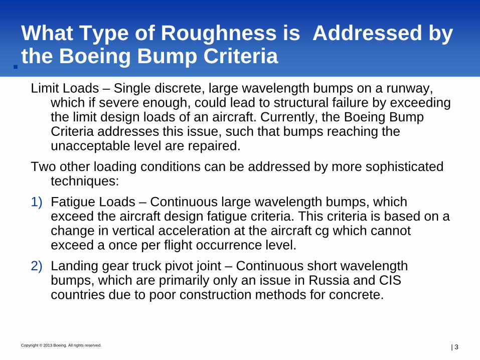
Limit Loads – Single discrete, large wavelength bumps on a runway, which if severe enough, could lead to structural failure by exceeding the limit design loads of an aircraft. Currently, the Boeing Bump Criteria addresses this issue, such that bumps reaching the unacceptable level are repaired.
Two other loading conditions can be addressed by more sophisticated techniques:
1) Fatigue Loads – Continuous large wavelength bumps, which exceed the aircraft design fatigue criteria. This criteria is based on a change in vertical acceleration at the aircraft cg which cannot exceed a once per flight occurrence level.
2) Landing gear truck pivot joint – Continuous short wavelength bumps, which are primarily only an issue in Russia and CIS countries due to poor construction methods for concrete.
Runway pavements should fill the following functions:
1.) Provide adequate bearing strength- addresses the structure of the pavement- ability to support aircraft loads
2.) Provide good ride quality- addresses surface geometrics and runway roughness- ability of aircraft to maneuver without incident
3.) Provide good surface friction characteristics- addresses texture and slope of pavement – ability to provide for adequate drainage and aircraft braking performance
All of these functions are tied to proper pavement maintenance ensuring the pavement is adequate for safe aircraft operations.
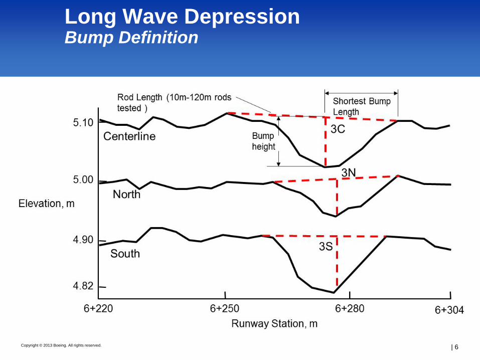
● Profile smoothing done prior to bump analysis to eliminate raw data roughness which is not necessarily affecting aircraft response. Data is curve fitted with a smooth spline every 200 meters. This flattens the profile to better observe roughness.
● Rod lengths to be checked start at 5m up to 120 m, increments of 5-10 m typically adequate.
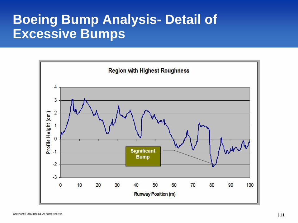
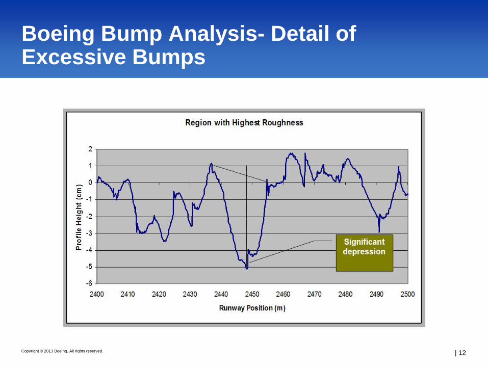
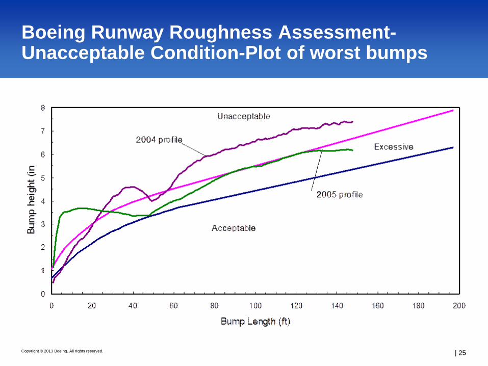
● Plot of worst bumps versus the Boeing criteria indicates areas needing repair. More detailed analysis can be done by plotting 100-200m profile segments.
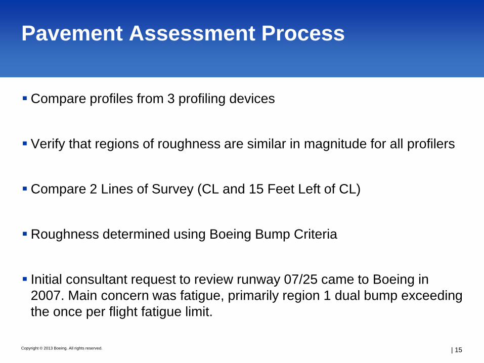
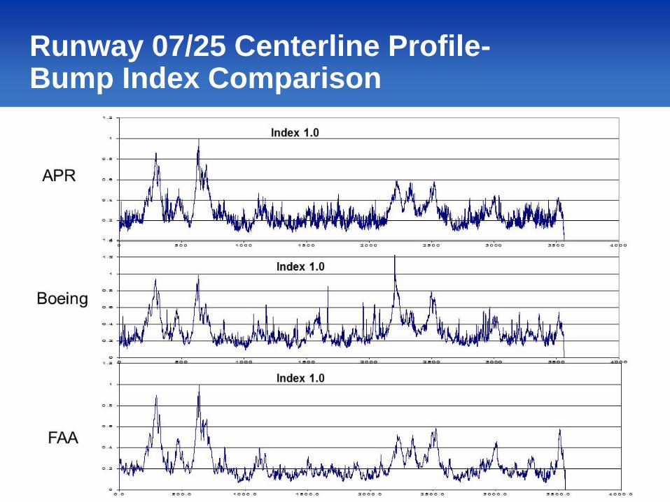
Verify that regions of roughness are similar in magnitude for all profilers
Compare 2 Lines of Survey (CL and 15 Feet Left of CL)
Roughness determined using Boeing Bump Criteria
Initial consultant request to review runway 07/25 came to Boeing in 2007. Main concern was fatigue, primarily region 1 dual bump exceeding the once per flight fatigue limit.
There is no industry standard which clearly defines when a airfield pavement has become “too rough”
Problems can be aircraft specific-i.e. heavier aircraft at high speed more susceptible to long wavelength bumps
New construction smoothness criteria is no longer applicable as pavement deteriorates
Action by the airport is typically initiated by pilot complaints- FAA currently doing aircraft simulator research to assess pilot feedback on runways of varying roughness.
Maximum grade allowance and changes in grade provisions
AC 150/5370-10F, Standards for Specifying Construction of Airports
Construction tolerances must be met
Acceptance criteria for smoothness- straightedge or profilograph
AC 150/5370-13A, Off-Peak Construction of Airport Pavements Using Hot Mix Asphalt
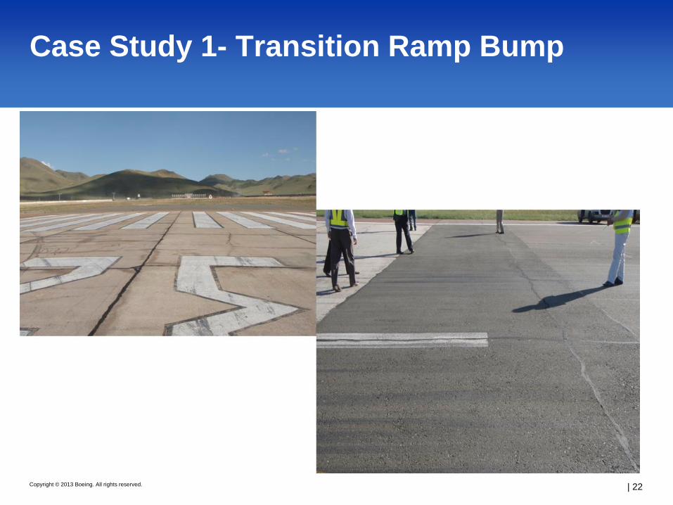
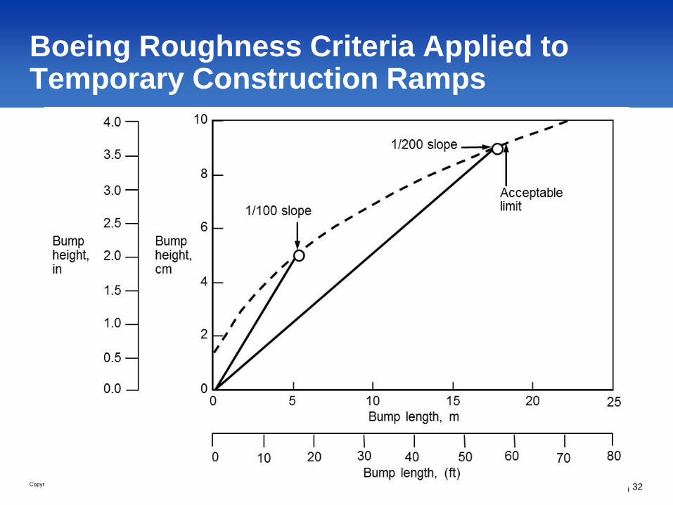
Temporary ramp guidance. Recommends longitudinal ramps of 4.5 m (15 ft) for each 25 mm (1 inch) of compacted overlay.
When practicable, it is recommended that the ramp proceed in the predominant aircraft direction resulting in “down” ramps. Avoids possible engine ingestion of loose material.
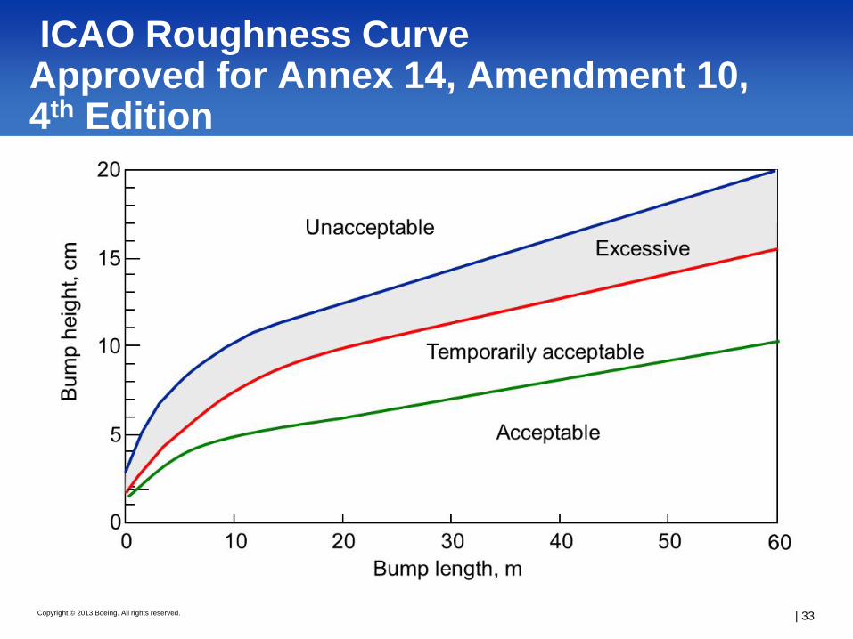
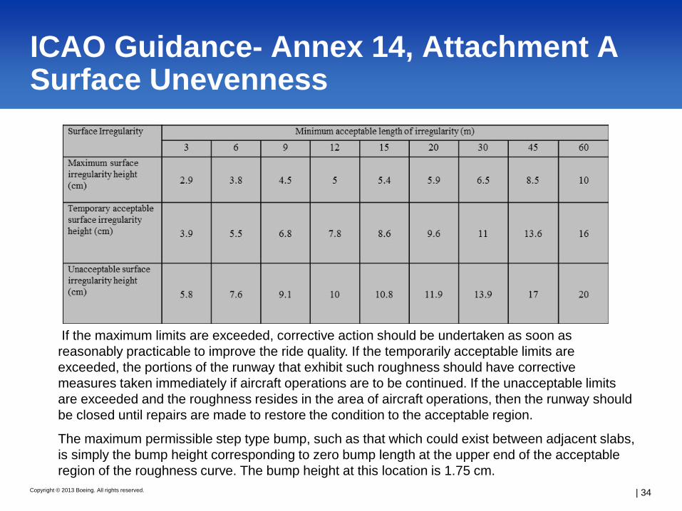
ICAO Guidance- Annex 14, Attachment A Surface Unevenness
| 34
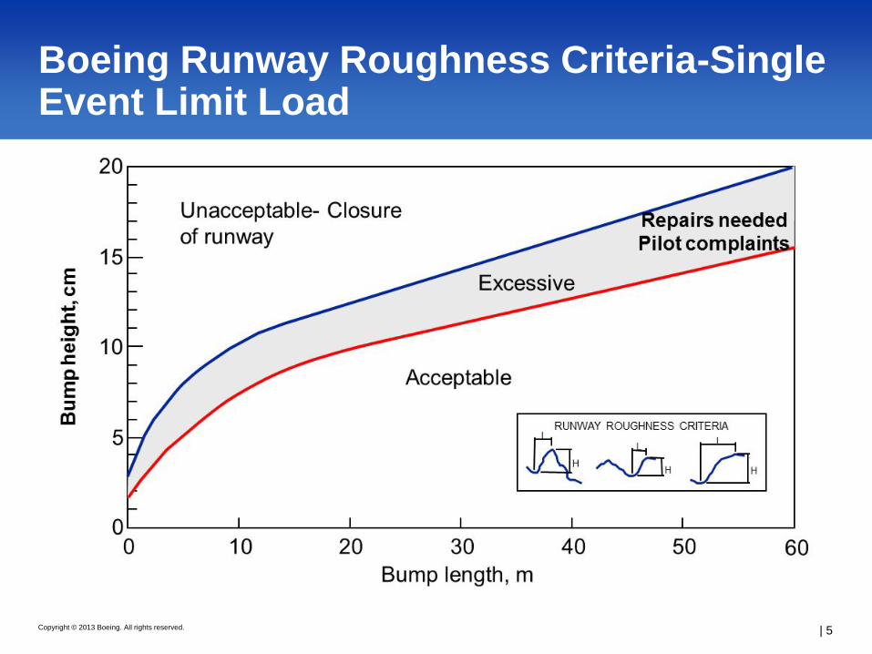
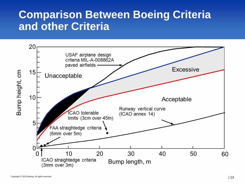
If the maximum limits are exceeded, corrective action should be undertaken as soon as reasonably practicable to improve the ride quality. If the temporarily acceptable limits are exceeded, the portions of the runway that exhibit such roughness should have corrective measures taken immediately if aircraft operations are to be continued. If the unacceptable limits are exceeded and the roughness resides in the area of aircraft operations, then the runway should be closed until repairs are made to restore the condition to the acceptable region.
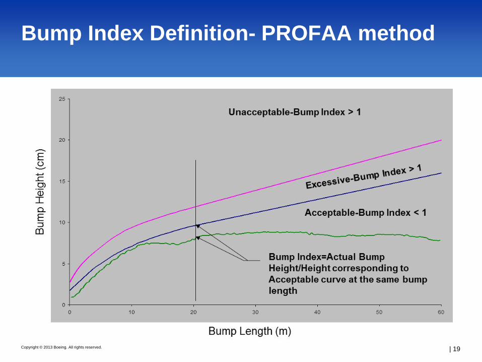
The maximum permissible step type bump, such as that which could exist between adjacent slabs, is simply the bump height corresponding to zero bump length at the upper end of the acceptable region of the roughness curve. The bump height at this location is 1.75 cm.
Current ASTM E1274 - 03(2012), Standard Test Method for Measuring Pavement Roughness Using a Profilograph, states that “Calculations can be done manually with the blanking band and excessive height templates or electronically with routines in a computer.” However, procedures for doing the calculations on a computer are not defined in the standard and suitable procedures had to be developed in order to perform the calculations using a computer program.
The excessive height templates in the current standard were defined for highways and are
based on a standard 25 ft (7.6 m) straightedge. The Boeing bump has to be implemented as an index rather than an excessive height template because the bump limit criteria varies with bump length.
The new standard will provide bump template simulation procedures with a bump height
and base length, in conjunction with the procedures for Boeing bump index computations in a computer program- preferably PROFAA.
Aircraft are susceptible to three types of roughness, and the Boeing Bump Criteria addresses single event long wavelength type roughness, and to some extent fatigue loading effects on aircraft. Short wave roughness typically only a concern in Russia and the CIS due to poor construction techniques.
Typical roughness problems based on Boeing experience in this area are the result of the following: Poor maintenance, failures in base and/or subbase materials, clay soils and issues dealing with moisture, and improper use of transition ramps.
Guidance is needed for airports on how to address and measure roughness. Recent ICAO acceptance of the Boeing Bump, working towards developing an ASTM standard, and the FAA advisory circulars and PROFAA software all provide technical guidance in this area.