8
Edwards Vacuum Pumps -Technical Data-

Edwards Vacuum Pumps-Technical Data-

T: +49 (0)89 15 980 280 - [email protected] - www.ScienceServices.eu
Please find our current prices at: www.ScienceServices.eu
© Edwards Limited 2011. All rights reserved. Page 7Edwards and the Edwards logo are trade marks of Edwards Limited.
Technical dataA652–01–880 Issue T
2 Technical dataNote: To comply with CSA standards, the pump must be installed and used indoors, and within the operating
conditions specified in Table 1 below.
2.1 Operating and storage conditions
2.2 Performance
2.2.1 General
Note: In Table 2 and Table 3, total pressures have been measured by a capacitance diaphragm gauge on a vacuum chamber without a cold trap, as specified by Pneurop Standard 6602 (1979).
Table 1 - Operating and storage conditions
Parameter Reference data
Ambient temperature range (operation) 12 to 40°C
Ambient temperature range (storage) –30 to 70°C
Normal surface temperature of the pump-body * 50 to 70°C
Maximum humidity (operation) 90% RH
Maximum altitude (operation) 2000 m
Pollution degree 2
Installation category II
* At ultimate vacuum, with ambient temperature of 20°C.
Table 2 - General performance data
Parameter Reference data
High Vacuum mode performance See Table 3
High Throughput mode performance See Table 4
Suckback protection 1 x 10⁻⁵ mbar l s-1, 1 x 10⁻³ Pa l s-1
Maximum initial pressure rise with no gas-ballast flow1 x 10-1 mbar, 10 Pa
RV3 RV5 RV8 RV12
Maximum displacement: m3 h-1
50 Hz electrical supply60 Hz electrical supply
3.74.5
5.85.0
9.711.7
14.217.0
Maximum pumping speed (Pneurop 6602, 1979): m3 h-1
50 Hz electrical supply60 Hz electrical supply
3.33.9
5.16.2
8.510.0
12.014.2
Maximum permitted inlet pressure and gas-ballast inlet pressure
bar gauge 0.5 0.5 0.5 0.5
Pa 1.5 x 10⁵ 1.5 x 10⁵ 1.5 x 10⁵ 1.5 x 10⁵
Maximum permitted outlet pressure
bar gauge 1 1 1 1
Pa 2 x 10⁵ 2 x 10⁵ 2 x 10⁵ 2 x 10⁵
1

T: +49 (0)89 15 980 280 - [email protected] - www.ScienceServices.eu
Please find our current prices at: www.ScienceServices.euA652–01–880 Issue T
Page 8©
Edwards Lim
ited 2011. All rights reserved.Edw
ards and the Edwards logo are trade m
arks of Edwards Lim
ited.
Technical data
Table 3 - Performance data: High Vacuum mode
HIGH VACUUM MODE
Parameter UnitsRV3 RV5 RV8 RV12
1-phase 3-phase 1-phase 3-phase 1-phase 3-phase 1-phase 3-phase
Gas-ballast control closed (position ‘0’)
Ultimate total pressure mbar 2 x 10⁻³ 2 x 10⁻³ 2 x 10⁻³ 2 x 10⁻³
Pa 2 x 10⁻¹ 2 x 10⁻¹ 2 x 10⁻¹ 2 x 10⁻¹
Gas-ballast control low flow (position ‘I’)
Ultimate total pressure mbar 3 x 10⁻² 3 x 10⁻² 3 x 10⁻² 3 x 10⁻²
Pa 3 3 3 3
Gas-ballast flow l min-1 5 5 5 5
Maximum water vapour pumping rate kg h-1 0.06 0.04 0.06 0.04 0.06 0.04 0.06 0.04
Maximum water vapour inlet pressure mbar 27 18 16 11 10 7 7 5
Pa 2.7 x 10³ 1.8 x 10³ 1.6 x 10³ 1.1 x 10³ 1 x 10³ 7 x 10² 7 x 10² 5 x 10²
Gas-ballast control high flow (position ‘II’)
Ultimate total pressure mbar 1.2 x 10⁻¹ 1 x 10⁻¹ 6 x 10⁻² 6 x 10⁻²
Pa 1.2 x 101 1 x 101 6 6
Gas-ballast flow l min-1 14 14 16 16
Maximum water vapour pumping rate kg h-1 0.22 0.12 0.22 0.12 0.22 0.20 0.29 0.25
Maximum water vapour inlet pressure mbar 80 54 50 32 38 34 32 28
Pa 8 x 10³ 5.4 x 10³ 5 x 10³ 3.2 x 10³ 3.8 x 10³ 3.4 x 10³ 3.2 x 10³ 2.8 x 10³
© Edw
ards Limited 2011. All rights reserved.
Page 9 Edw
ards and the Edwards logo are trade m
arks of Edwards Lim
ited.
Technical data
A652–01–880 Issue T
Table 4 - Performance data: High Throughput mode
HIGH THROUGHPUT MODE
Parameter UnitsRV3 RV5 RV8 RV12
1-phase 3-phase 1-phase 3-phase 1-phase 3-phase 1-phase 3-phase
Gas-ballast control closed (position ‘0’)
Ultimate total pressure mbar 3 x 10⁻² 3 x 10⁻² 3 x 10⁻² 3 x 10⁻²
Pa 3 3 3 3
Gas-ballast control low flow (position ‘I’)
Ultimate total pressure mbar 6 x 10⁻² 6 x 10⁻² 4 x 10⁻² 4 x 10⁻²
Pa 6 6 4 4
Gas-ballast flow l min-1 5 5 5 5
Maximum water vapour pumping rate kg h-1 0.06 0.04 0.06 0.04 0.06 0.04 0.06 0.04
Maximum water vapour inlet pressure mbar 27 18 16 11 10 7 7 5
Pa 2.7 x 10³ 1.8 x 10³ 1.6 x 10³ 1.1 x 10³ 1 x 10³ 7 x 10² 7 x 10² 5 x 10²
Gas-ballast control high flow (position ‘II’)
Ultimate total pressure mbar 1.2 x 10⁻¹ 1 x 10⁻¹ 6 x 10⁻² 6 x 10⁻²
Pa 1.2 x 101 1 x 101 6 6
Gas-ballast flow l min-1 14 14 16 16
Maximum water vapour pumping rate kg h-1 0.22 0.12 0.22 0.12 0.22 0.20 0.29 0.25
Maximum water vapour inlet pressure mbar 80 54 50 32 38 34 32 28
Pa 8 x 10³ 5.4 x 10³ 5 x 10³ 3.2 x 10³ 3.8 x 10³ 3.4 x 10³ 3.2 x 10³ 2.8 x 10³
2
T: +49 (0)89 15 980 280 - [email protected] - www.ScienceServices.eu
Please find our current prices at: www.ScienceServices.euA652–01–880 Issue T
Page 10©
Edwards Lim
ited 2011. All rights reserved.Edw
ards and the Edwards logo are trade m
arks of Edwards Lim
ited.
Technical data
Table 5 - Performance characteristics
MODESELECTORPOSITION
GAS BALLAST CONTROL
Closed (position ‘0’) Low flow (position ‘I’) High flow (position ‘II’)
High Vacuum mode Ultimate total pressure Ultimate total pressure Ultimate total pressure
mbar Pa mbar Pa mbar Pa
2 x 10⁻³ 2 x 10⁻¹ 3 x 10⁻² 3 1.2 x 10⁻¹ (RV3)1.0 x 10⁻¹ (RV5)6 x 10⁻² (RV8/12)
1.2 x 101 (RV3)1.0 x 101 (RV5)6.0 (RV8/12)
Use for the bestultimate pressure
Maximum water vapour pumping rate Maximum water vapour pumping rate
1-phase pumps 3-phase pumps 1-phase pumps 3-phase pumps
0.06 kg h-1 0.04 kg h-1 0.22 kg h-1 (RV3/5/8)0.29 kg h-1 (RV12)
0.12 kg h-1 (RV3/5)0.20 kg h-1 (RV8)0.25 kg h-1 (RV12)
High Throughput mode Ultimate total pressure Ultimate total pressure Ultimate total pressure
mbar Pa mbar Pa mbar Pa
3 x 10⁻² 3 6 x 10⁻² (RV3/5)4 x 10-2 (RV8/12)
6 (RV3/5)4 (RV8/12)
1.2 x 10⁻¹ (RV3)1.0 x 10⁻¹ (RV5)6 x 10⁻² (RV8/12)
1.2 x 101 (RV3)1.0 x 101 (RV5)6.0 (RV8/12)
Use for continuous inlet pressure above
50 mbar/5 x 103 Pa
Maximum water vapour pumping rate Maximum water vapour pumping rate
1-phase pumps 3-phase pumps 1-phase pumps 3-phase pumps
0.06 kg h-1 0.04 kg h-1 0.22 kg h-1 (RV3/5/8)0.29 kg h-1 (RV12)
0.12 kg h-1 (RV3/5)0.20 kg h-1 (RV8)0.25 kg h-1 (RV12)
© Edwards Limited 2011. All rights reserved. Page 11Edwards and the Edwards logo are trade marks of Edwards Limited.
Technical data
A652–01–880 Issue T
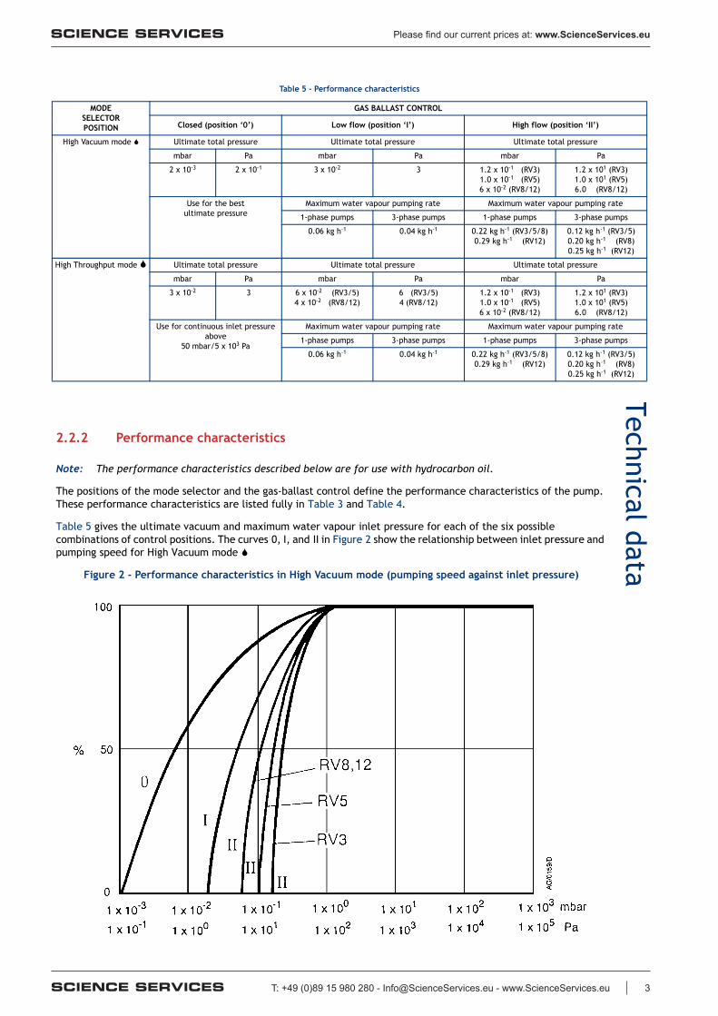
2.2.2 Performance characteristics
Note: The performance characteristics described below are for use with hydrocarbon oil.
The positions of the mode selector and the gas-ballast control define the performance characteristics of the pump. These performance characteristics are listed fully in Table 3 and Table 4.
Table 5 gives the ultimate vacuum and maximum water vapour inlet pressure for each of the six possible combinations of control positions. The curves 0, I, and II in Figure 2 show the relationship between inlet pressure and pumping speed for High Vacuum mode
Figure 2 - Performance characteristics in High Vacuum mode (pumping speed against inlet pressure)
3

T: +49 (0)89 15 980 280 - [email protected] - www.ScienceServices.eu
Please find our current prices at: www.ScienceServices.eu
A652–01–880 Issue T
Page 12 © Edwards Limited 2011. All rights reserved.Edwards and the Edwards logo are trade marks of Edwards Limited.
Technical data
2.3 Mechanical data
2.4 Noise and vibration data
2.5 Lubrication data
Note: Edwards Material Safety Data sheets for the rotary pump oils are available on request.
Table 6 - Mechanical data
Parameter Reference data
Dimensions See Figure 3
Degree of protection (IEC 34-5: 1981)
Single-phase pumpsThree-phase pumps
IP44IP54
Maximum tilt angle 10°
Motor rotational speed
50 Hz electrical supply60 Hz electrical supply
1470 r min-1
1760 r min-1
Maximum mass RV3 RV5 RV8 RV12
Pumps with motor, without oil 23.3 kg 23.2 kg 26.0 kg 26.3 kg
Bareshaft pumps 14.0 kg 14.0 kg 16.5 kg 17.5 kg
Table 7 - Noise and vibration data
Parameter Reference data
Sound pressure*
* Measured at ultimate vacuum 1 metre from the end of the pump to ISO 11201, High Vacuum mode S, 50 Hz operation.
Single-phase pumpsThree-phase pumps
48 dB (A)50 dB (A)
Vibration severity†
† Measured at the inlet port to ISO 2372 (1974)
Single-phase pumpsThree-phase pumps
Class 1CClass 1C
Table 8 - Lubrication data
Parameter Reference data
Recommended oil*
* To operate the pump when the ambient temperature is outside the limits specified in Section 2.1, or to optimise the pump performance when you pump condensible vapours, you may need to use a different oil.
Hydrocarbon-prepared pumpsPFPE-prepared pumps
Edwards Ultragrade 19Krytox 1506 or Fomblin 06/6
Oil capacity RV3 RV5 RV8 RV12
Maximum 0.70 litres 0.70 litres 0.75 litres 1.00 litres
Minimum 0.42 litres 0.42 litres 0.45 litres 0.65 litres
4

T: +49 (0)89 15 980 280 - [email protected] - www.ScienceServices.eu
Please find our current prices at: www.ScienceServices.eu
© Edwards Limited 2011. All rights reserved. Page 13Edwards and the Edwards logo are trade marks of Edwards Limited.
Technical dataA652–01–880 Issue T
Figure 3 - Dimensions (mm)
1. On-off switch (single-phase pumps only)2. Lifting bracket (Not fitted to RV3 and RV5
pumps: a lifting handle is fitted instead)
A. Top view of single-phase pumpB. Side view of single-phase pumpC. Side view of three-phase pumpD. Front view of single-phase pumpE. Side view of bareshaft pump
Pump A*
* Single-phase pumps.
A†
† Three-phase pumps.
B C D E F G H I J K
RV3 430 429 158 225 127 29 78 230 120 37 32 –
RV5 430 429 158 225 127 29 78 230 120 37 32 –
RV8 470 429 158 225 161 35 78 230 120 37 32 261
RV12 439 429 158 225 181 35 78 230 120 37 32 261
5

T: +49 (0)89 15 980 280 - [email protected] - www.ScienceServices.eu
Please find our current prices at: www.ScienceServices.eu
A652–01–880 Issue T
Page 14 © Edwards Limited 2011. All rights reserved.Edwards and the Edwards logo are trade marks of Edwards Limited.
Technical data
2.6 Electrical data: single-phase pumps
Note: We recommend that you use fuses of the maximum ratings specified in Table 9 and Table 10. You must not use fuses of a higher rating.
The dual-voltage, dual-frequency motor is designed for a single-phase electrical supply and is suitable for 50 Hz or 60 Hz operation. The motor can be manually switched between nominal supply voltages of 110–120 V and 220-240 V (refer to Section 3.7.1).
When you start a cold pump, the motor will draw the start-up current shown in Table 9 and Table 10 for up to several seconds, so you must use a slow-blow fuse to prevent unnecessary fuse failure during pump start-up. Within five minutes, as the oil in the pump warms up, the current drawn will slowly reduce to the full load current specified in Table 9 and Table 10.
Note: The fuse type chosen should be either a time delay type CC or a type M, or (in the UK) they should be to BS 88.
Table 9 - Electrical data (single-phase pumps with Item Numbers -903 or -906)
PumpNominalsupply
(V)
Frequency(Hz)
Power(W)
Full load current
(A)
Start-upcurrent
(A)
Maximumfuse rating
(A)
RV3 and RV5 220–240 50 250 2.7 17.0 5
230–240 60 300 2.1 17.0 5
110 50 250 4.6 30.8 10
115–120 60 300 4.4 30.8 10
RV8 and RV12 220–240 50 450 3.4 17.0 5
230–240 60 550 3.4 18.0 5
110 50 450 7.8 34.0 13
115–120 60 550 6.9 30.8 13
Table 10 - Electrical data (single-phase pumps with Item Numbers -904)
PumpNominalsupply
(V)
Frequency(Hz)
Power(W)
Full load current
(A)
Start-upcurrent
(A)
Maximumfuse rating
(A)
RV3 and RV5 200 50 250 2.7 17.0 5
200–210 60 300 2.1 17.0 5
100 50 250 5.4 30.8 10
100–105 60 300 4.6 30.8 10
RV8 and RV12 200 50 450 3.4 17.0 5
200–210 60 550 3.4 20.6 5
100 50 450 7.6 40.0 13
100–105 60 550 6.9 30.8 13
6

T: +49 (0)89 15 980 280 - [email protected] - www.ScienceServices.eu
Please find our current prices at: www.ScienceServices.eu
© Edwards Limited 2011. All rights reserved. Page 15Edwards and the Edwards logo are trade marks of Edwards Limited.
Technical dataA652–01–880 Issue T
2.7 Electrical data: three-phase pumps
The dual-voltage, dual-frequency motor is designed for a three-phase electrical supply and is suitable for 50 Hz or 60 Hz operation. The motor can be manually switched between nominal supply voltages of 220–240 V and 380–460 V (refer to Section 3.8.1). Pumps are supplied preset for nominal 380–460 V electrical supplies.
When you start a cold pump, the motor will draw the start-up current shown in Table 11 for up to 0.5 seconds. The current will then reduce quickly as the motor reaches rated rotational speed. Within 5 minutes, as the oil and pump warms up, the current drawn will slowly reduce to a maximum of the full load current specified in Table 11.
When you start a warm pump, the motor will draw the start-up current shown in Table 11 for up to 0.5 seconds. The current drawn will then immediately fall to a maximum of the full load current.
Electrical short-circuit and ground-fault protection of the pump will be provided by fitting Class CC fuses of the values shown in Table 11 at the point of connection to the supply. If these are not available in your country of use, Type aM European fuses of the same rating can also be used.
Table 11 - Electrical data (three-phase pumps with Item Numbers -905)
PumpNominalsupply
(V)
Frequency(Hz)
Power(W)
Full load current
(A)
Start-upcurrent
(A)
Maximumfuse rating
(A)
RV3 and RV5 220–240 50 250 1.7 10.2 2.5
200–230 60 300 1.7 10.2 2.5
380–415 50 250 1.0 5.7 2.5
460 60 300 1.0 7.0 2.5
RV8 and RV12 220–240 50 450 2.5 14.0 4.0
200–230 60 550 2.9 12.0 4.0
380–415 50 450 1.5 9.0 2.5
460 60 550 1.5 8.7 2.5
7


