Page 1
REPUBLIC OF RWANDA
RWANDA UTILITIES REGULATORY AGENCY
P.O BOX 7289 KIGALI, Tel: +250 252 584562,
Fax: +250 252 584563
Email: [email protected]
Website: www.rura.gov.rw
GUIDELINES GUIDELINES GUIDELINES GUIDELINES FOR FIBER OPTIC CABLES UNDERGROUND INSTALLATIONFOR FIBER OPTIC CABLES UNDERGROUND INSTALLATIONFOR FIBER OPTIC CABLES UNDERGROUND INSTALLATIONFOR FIBER OPTIC CABLES UNDERGROUND INSTALLATION
IIIISSUED SSUED SSUED SSUED BBBBYYYY
RRRREGULATORY EGULATORY EGULATORY EGULATORY BBBBOARD OARD OARD OARD
RRRRWANDA WANDA WANDA WANDA UUUUTILITIES TILITIES TILITIES TILITIES RRRREGULATORY EGULATORY EGULATORY EGULATORY AAAAGENCY GENCY GENCY GENCY –––– ((((RURARURARURARURA))))
SSSSERIAL ERIAL ERIAL ERIAL NNNNUMBER UMBER UMBER UMBER 00…/RURA/20100…/RURA/20100…/RURA/20100…/RURA/2013333
DATED THISDATED THISDATED THISDATED THIS ………… 201………… 201………… 201………… 2013333
Page 2
i
TABLE OF CONTENT
PREAMBLE ......................................................................................................................................................III
CHAPTER 1: GENERAL PROVISIONS ................................................................................................................. 1
ARTICLE 1: PURPOSE........................................................................................................................................... 1
ARTICLE 2: SCOPE ............................................................................................................................................... 1
ARTICLE 3: DEFINITIONS ..................................................................................................................................... 1
CHAPTER 2: SPECIFICATIONS FOR FIBER OPTIC NETWORK ............................................................................... 3
AND CABLES ..................................................................................................................................................... 3
ARTICLE 4: FIBER OPTIC SPECIFICATIONS ........................................................................................................... 3
ARTICLE 5: CABLE SPECIFICATIONS.................................................................................................................... 3
CHAPTER 3: FOC NETWORK ENGINEERING REQUIREMENTS ............................................................................ 4
FOR PERMIT APPLICATION ............................................................................................................................... 4
SECTION 1. DESIGN STAGES AND SUBMISSIONS .............................................................................................. 4
ARTICLE 6. PERMIT APPLICANT REQUIREMENT DURING DESIGN STAGE............................................................... 4
ARTICLE 7. PLAN DOCUMENTS ............................................................................................................................ 4
ARTICLE 8. DRILLING SITE INFORMATION TO BE SUBMITTED WITH PERMIT DEMAND ...................................... 5
SECTION2. PERMIT APPLICATION CHARACTERISTICS ....................................................................................... 6
ARTICLE 9. SEPARATE PERMITS REQUIRED......................................................................................................... 6
ARTICLE 10. WORKS NOTIFICATION ................................................................................................................... 6
ARTICLE 11. LIMITATIONS .................................................................................................................................. 6
SECTION 3. INSTALLATION ............................................................................................................................... 6
ARTICLE 12. MANHOLES/ HANDHOLES INSTALLATION ....................................................................................... 6
ARTICLE 13. ROAD /STREET LABELING .............................................................................................................. 7
ARTICLE 14. CABLE INSTALLATION ALONG ROADWAY ...................................................................................... 7
ARTICLE 15. EXISTING UTILITY DAMAGES ......................................................................................................... 8
ARTICLE 16. CLEANING ..................................................................................................................................... 8
ARTICLE 17. TRENCHING GUIDANCE .................................................................................................................. 8
ARTICLE 18. TRENCHLESS TECHNIQUES ............................................................................................................. 9
ARTICLE 19. TRENCHLESS GUIDANCE .............................................................................................................. 10
ARTICLE 20. CROSSINGS ................................................................................................................................... 10
ARTICLE 21. DUCT SHARING ............................................................................................................................ 10
ARTICLE 22. SHARING POINT AND SHARED BUILDING CABLING ...................................................................... 11
CHAPTER 4. AS BUILT SITE VISIT AND REPORTING ......................................................................................... 12
ARTICLE 23 AS- BUILT SITE VISIT .................................................................................................................... 12
ARTICLE 24 FINAL AS-BUILT REPORTING......................................................................................................... 12
ARTICLE 25 ACTIVE PERMITS ........................................................................................................................... 13
CHAPTER 5. FINAL PROVISIONS ..................................................................................................................... 14
ARTICLE 26. ENFORCEMENT NOTICE ................................................................................................................. 14
Page 3
ii
ARTICLE 27. COMMENCEMENT ......................................................................................................................... 14
APPENDIX ...................................................................................................................................................... 15
APPENDIX1. APPLICATION FORM FOR RIGHT-OF –WAY AUTHORIZATION/FOC INSTALLATION (TO BE COMPLETED IN DUPLICATE) .. 15
APPENDIX2. RECOMMENDED PARAMETERS TO BE INCLUDED IN THE LINK LOSSES CALCULATION. ........................................... 17
APPENDIX3. OPTICAL PERFORMANCE FOR STANDARD (ITU-T G652) SINGLE MODE FIBRES ................................................ 17
APPENDIX4. OPTICAL PERFORMANCE FOR MULTIMODE FIBRES (ITU-T G651.1) .............................................................. 17
APPENDIX5. SUMMARY OF VALUES RECOMMENDED BY THESE GUIDELINES ..................................................................... 18
Page 4
iii
PREAMBLE
The Regulatory Board of the Rwanda Utilities Regulatory Agency (RURA),
Pursuant to the Law n° 39/2001 of 13/09/2001establishing an agency for the regulation of
certain Public Utilities, particularly in its articles 5 and 13;
Considering the law n° 44/2001 of 30/11/2001 governing telecommunications, especially in its
articles 47, 48, 49 and 50;
Considering the Ministerial Order no: 6/DC/04 of 07/06/2004 on requests for installation of
telecommunications facilities and terminal equipment on public and private property;
Considering ITU-T recommendations on Construction, installation and protection of cables
and other elements of outside plant (L series);
Considering the need of RURA to have a framework to regulate the telecommunications
sector, enhance and deploy services in compliance with the most advanced technology to
meet user’s needs at the most suitable prices.
AND AFTER its deliberations in its meeting of ……………;
HEREBY issues the following guidelines on Fiber Optic Cables Underground installation
Page 5
1
CHAPTER 1: GENERAL PROVISIONS
Article 1: Purpose
These guidelines on fiber optic cables underground installation aim at avoiding any damage
to existing underground infrastructure such as existing FOC, sewage or water pipes, electrical
cables or other telecommunications cables. They also intend to insure that the installation of
FOC is done in accordance with telecommunication standards.
Article 2: Scope
These guidelines apply to all Fiber optic infrastructure underground installation and show the
mostly used materials specifications for FOC network.
These guidelines shall apply to any Telecom Operators and Service Providers operating
within the territory of the Republic of Rwanda.
Article 3: Definitions
In these guidelines the terms hereunder shall have the following meaning:
Fiber Optic or Optic Fiber means the medium and the technology associated with the
transmission of information as light pulses along a glass or plastic strand or fiber.
FOC means Fiber Optic Cable which means a telecommunication cable in which one or more
fiber optic are used as the propagation medium to transmit large amounts of information at
the speed of light;
Hand hole means a top opening hole with small size than manhole for pulling and splicing
cables only;
ITU-T means International Telecommunication Union -Telecommunication Standardization
Sector;
Manhole means top opening large and deep hole where a man can get inside for installation,
making connections or performing maintenance on underground and buried FOC and other
services including sewers, telephone, electricity, storm drains and gas ;
Permit shall refer to the document issued by the Regulatory Agency which authorizes the
permit holder to carry out the activity specified under the conditions prescribed in these
guidelines;
Regulatory Board means the board of individuals responsible for the regulation of public
utilities in the Rwandan Republic and for the management of the Regulatory Agency, as
defined by the Law;
Page 6
2
Right of way means the right to pass through over someone's land and to have the reasonable
use and enjoyment of their property as long as it is not inconsistent with the network
provider's use and enjoyment of the land;
RURA shall mean Rwanda Utilities Regulatory Agency as defined by the Law N° 39/2001 of
13 September 2001 establishing an Agency for the regulation of certain public utilities;
TIA means Telecommunication Industry Association;
Page 7
3
CHAPTER 2: SPECIFICATIONS FOR FIBER OPTIC NETWORK
AND CABLES
Article 4: Fiber Optic specifications
The following features should be taken into consideration while choosing fibre optic and
cable
• All fibre optics must meet the requirements of ITU-T Recommendations.
• Each cable must have traceability of the fibre optic back to the original fibre ID
number and test parameters as provided by the fibre manufacturer
• Each fibre must be distinguishable from other fibres in the same duct by means of
colour coding ink visible throughout the design life of the cable (as Defined by TIA-
5987C).
• Fibre optics shall have a high level of splice compatibility with fibre optics from other
manufacturers.
Performance specifications for standard single mode Fibre optic (ITU-T G.652) and
recommended multimode Fibre optics (ITU-T G.651) are detailed in Appendix3 and 4.
Article 5: Cable Specifications
The cables must be circular in cross section and free from pinholes, joints, repairs and
other defects.
Materials used in the construction of the cable shall not affect the physical or optical
properties of the fibres and shall be compatible with each other.
The above mentioned provisions (Article4 and Article5) comprise requirements for
the mostly used materials for FOC network and its specifications. However, it remains
the network provider responsibility to identify and procure all the required materials
for the complete FOC installation work
Page 8
4
CHAPTER 3: FOC NETWORK ENGINEERING REQUIREMENTS
FOR PERMIT APPLICATION
Section 1. Design stages and submissions
Article 6. Permit applicant requirement during design stage
a. A physical pre-survey of the route for all types of installations for the purpose of
establishing the exact cable routing, termination points, jointing locations and cutting
lengths will be done before the commencement of any work or committing any
materials. If a change in route is required for any practical reason, prior approval
should be obtained from the regulatory agency.
b. Optical power link loss budget shall be calculated for any FOC link. Parameters to be
included in calculation of link losses are specified in appendix2.
c. The maximum length of any optical path between two fibre optic repeaters must be
calculated separately, and depends on the total loss in all components used in the path,
including fibre optic cable, optical connectors, star couplers, and splices.
d. All components such as additional connectors, star couplers and splices along with
cable attenuation, should be taken into account in calculating the loss.
e. The sum of the losses in all components used in the optical path must not exceed the
specified Power Loss Budget for the chosen cable type.
f. The specified Power Loss Budget includes the loss of the two ST–type connectors
connecting at the two repeater ends, and also includes the system margin of 3 dB.
Article 7. Plan documents
Plan document should include
1. One original complete copy of the plans showing the proposed work, schedule and
procedures. However an additional copy will be required if there is a bridge
attachment, road crossing, box culvert crossing, limited access or inter-district
involved.
2. The route/ street name/ location where the work is to be performed.
3. Color highlights to show the demanded right-of-way (red) and the existing cable
(blue).
4. A vicinity map or drawing showing the routes, total layout and locations of all
manholes that will be included in the permit, and the surrounding area of the work.
Page 9
5
5. Legend showing the symbols used on the plans and the color-coding used to mark the
plan if more than red and blue colors are used.
6. A clearance distance of the minimum vertical (while crossing) and the horizontal
(while in parallel) distance to the nearest affected utility and/or right-of-way object.
7. Section views:
a) Shall not include sections that are not relevant to the proposed work.
b) For any crossing, which might create a potential conflict including but not
limited to, cable crossings over or under large storm pipes, culverts, electrical
lines, water, transmission lines and other affected utilities, an individual
section views must be submitted.
c) Any proposed work in the vicinity of a bridge or box culvert must include a
section showing the distance from all features of the structure.
8. Labeling
a) Indicate the length and type of cable proposed for installation on each page.
b) Show distance of proposed cable from the roadway.
c) Identify the proposed cable installation method on each plan sheet such as
hand, machine trenching, or directional bore.
Article 8. Drilling Site Information to Be Submitted With Permit Demand
Exhaustive knowledge of the work site and of the subsoil, right from the first design phases is
essential, both to reduce the number of failures and/or to limit possible damage to pre-
existing services or structures. Information requested by Regulatory Agency to be submitted
with installation permit request is following:
– Existing utilities documentation made available by local authorities and other
companies.
– Site investigation equipments used such as Pipe and cable locators or
Ground Penetrating Radar systems,...
– The drilling plan accompanied by obstacles;
– Infill materials (rubble, sand).
Page 10
6
Section2. Permit application characteristics
An applicant must comply with the following:
a) Applicant should submit filled right of way form provided in Appendix1 of these
regulations.
b) The demand of permit should be accompanied by the documents listed in design
stages and submissions part.
c) Permit application must be in the name of the fiber optic network provider that is
responsible for the installation and maintenance of the cable and the signature of
applicant must appear on permit application.
d) Permit application shall list the name, address, phone number, and emergency 24-
hours phone number of the contact person for the fiber optic network provider.
Sub-contractor information may be provided separately.
e) Permit application documents should be submitted in soft and hard copy to the
Regulatory Agency office.
Article 9. Separate Permits Required
Work on the inter-district must be submitted on separate permit applications, and the
expected date of permits intersection work is to be determined.
Article 10. Works Notification
The list of routes/street names/locations where the work is to be conducted should be
communicated to other utilities providers prior permit request with a copy to the Regulatory
Agency. Comments from concerned utilities providers will be provided within 10 days from
the date of the reception of works notification.
Article 11. Limitations
Permit will be issued for applications on any exceeding distance. It is prohibited to conduct
any work on additional distance out of permit scope.
Section 3. INSTALLATION
Article 12. Manholes/ Handholes Installation
Each and only each manhole/ handhole constructor should obey the following:
Page 11
7
a) Manholes/Handholes shall be covert by a flat lid on which the size and the depth of
the manhole/handhole are written.
b) Manhole/Handhole lids shall be labeled with the network provider name.
c) Manholes/ Handholes must be located outside of sidewalks and roadways.
Manholes/Handholes must be located a minimum of 2 meters off the edge of
pedestrian way, and 3m from the off of the roadway if there is no space reserved for
pedestrian way. In case of unavailability of the required clearance distance due to the
soil or terrain condition; the request for shorter clearance shall be accompanied by soil
test result approved by an engineer in charge of infrastructure from concerned
institutions where the installation work will be conducted.
d) Manholes/Handholes shall not be located in the ditch line.
e) Any FOC joint shall be housed inside the manhole.
f) The pulling of the cable shall be hand assisted at each Manhole or Handhole. The
cable shall not be crushed or forced around a sharp corner. Sufficient slack shall be
left at each end of the cable to allow proper cable termination.
g) The cable shall be marked and labelled at each manhole and at all entry and end points
of the fibre optic cables.
h) The area around the manhole shall be compacted. Upon final acceptance of the
conduit/duct system all manholes shall be free of debris.
Article 13. Road /Street Labeling
Surface markers to indicate the route of the cables shall be planted by the road sides. These
markings shall be placed at intervals of between 300m to 500m.Visible tape marking shall
indicate the fiber network provider and cable depth. It shall be placed along the trenches 30
cm below ground surface.
Article 14. Cable Installation along Roadway
Cable installation along Road way shall strictly observe the following requirements:
– The cables shall be laid in ducts buried to depths of not less than 80 cm.
– Comply with all provisions and guidelines established by the Regulatory Agency and
local authorities
– Comply with the provided schedule and not go beyond three (3) days.
– Reserve at least the horizontal distance of 1 metre between the existing underground
utilities and the new cable, and if not possible provide an appropriate duct protection
Page 12
8
and make informed the network provider of existing utility five days before
excavation.
– Place the barriers and road signs required by current laws during excavation works.
– If the excavation must remain open or the road will be otherwise obstructed during
the night or under low-visibility conditions, road signs shall be complemented by
lighting devices of the color, shape and size stipulated by the traffic code.
– Trenches should be backfilled to the original state and backfill shall be strong enough
to support any kind of stresses.
– Put an identification sign (marker) stated by these guidelines to illustrate your cable
route.
Article 15. Existing Utility Damages
In case of damages of any existing infrastructure, the applicant shall negotiate the way to
restore the damages caused in a period of two weeks from the declaration of damages; if the
negotiations fail, the provisions stipulated by article 49 of the Law n° 44/2001 will be applied.
Article 16. Cleaning
The following operations shall be carried out after excavating the trench:
– Remove spoils from the sides of the excavation (Spoil must be transported to
authorized disposal sites in accordance with local authority requirements.)
– Remove adjacent paving materials which were damaged as a result of excavation.
– Fulfill the cleaning conditions required by local authority.
Article 17. Trenching Guidance
During the installation in trench the following should be obeyed
a. Fiber optic cables shall be laid in trenches.
Trenches along road networks shall be sufficiently deep to provide appropriate fiber
cable protection and shall be placed at least 1.5m away from the edge of pedestrian
walkways or storm drainages along paved roads. In case of unavailability of the
required clearance distance due to the soil or terrain condition; the request for shorter
clearance shall be accompanied by soil test result approved by an engineer in charge
of infrastructure from concerned institutions where the installation work will be
conducted.
b. In the absence of pedestrian walkways, the cable must be located at a minimum
distance of 2.5 meters off the roadway. In case of unavailability of the required
Page 13
9
clearance distance due to the soil or terrain condition; the request for shorter clearance
shall be accompanied by soil test result approved by an engineer in charge of
infrastructure from concerned institutions where the installation work will be
conducted
c. Road surfaces where cable crossings have been installed shall be restored to its
original state in compliance with local authorities’ specifications.
d. No cable installation will be permitted in a ditch line. Cable installations will be
permitted along the back of the ditch line only.
e. Where there are cable crossings along roads, ducting shall be of galvanized steel pipes
buried deep enough (1m or more) for protection from vehicular or pedestrian traffic
stresses. Similar galvanized steel pipe ducts shall be used at bridge crossings.
Article 18. Trenchless Techniques
Trenchless techniques shall be used to reduce environmental damage, social costs and
provide an economic alternative to open-trench methods of installation
Trenchless or no-dig technique used for long section FOC installation should be divided into
shorter sections of the work length accordingly to the characteristics of the machines and the
design requirements.
The trenchless techniques after consulting the relevant institutions are only allowed by
Regulatory Agency for road crossing FOC installation. The installation of optical cables
inside sewer ducts is compulsory wherever the ducts are available.
For the use of inside sewer ducts, the sewer assessment is much needed and the following
information shall escort the permit application:
– Applicable sewer pipe diameter
– Position in the sewer
– Maintenance feasibility of the sewer
– Risk of blockage
– Upgrading of the optical network
– Maximum number of cables and fibres
– Flexibility of the optical network
– Access to optical network
– Cable type
Other technique than the installation of optical cables inside sewer ducts agreed by
Regulatory Agency for road crossing is drilling technique which is allowed to be used in
absence of constructed ducts.
In case of impossible crossing with trenchless techniques due to the soil condition that avoids
the use of guided boring/directional drilling machine; an additional request for road crossing
Page 14
10
by digging accompanied by soil test result approved by an engineer in charge of
infrastructure from concerned institutions where the installation work is conducted is
required.
Article 19. Trenchless Guidance
Any person conducting trenchless excavation shall take all reasonable steps necessary to
protect and support underground utility lines. These steps shall include, but are not limited to
the following:
– The excavator should verify that all utility lines in the area are marked.
– The excavator shall ensure that bore equipment stakes are installed at a safe distance
from marked utility lines
– The excavator shall ensure that sufficient clearance is maintained between the bore
path and any underground utility lines during pullback.
– The excavator shall give special consideration to water, electricity and sewer systems
within the area that cannot be located accurately.
– The excavator shall ensure that the drill head locating device is functioning properly
and within its specification.
Article 20. Crossings
– All crossings are to be made perpendicular to the roadway.
– Road crossing machines should be used with a depth of not less than 1m.
– Any cables should be protected with appropriate ducts along the whole crossing
length.
Article 21. Duct Sharing
Fiber Optic installation conductor shall install at least four pipes in order to use one and
reserve remaining three for future use of another provider. The payment of these reserved
pipes by a new operator will follow the Guidelines for fiber and duct sharing.
Page 15
11
Article 22. Sharing Point and Shared Building Cabling
The shared building cabling and sharing point for fiber installation in building with
multiple operators is mandatory in order to:
– Reduce fiber installation and maintenance costs in the building
– Reduce disturbance (noise, infrastructure works, dust…) for inhabitants
– Avoid cabling duplication if more than one Fiber to the home (FTTH) operators are
in a building
The Shared building cabling combined with the sharing point should support both Point to
Point and Point to Multipoint access network topologies.
The first applicant to connect a building should provide a sharing point that might support
sharing of four operators in case of need to share the cable.
Page 16
12
CHAPTER 4. AS BUILT SITE VISIT AND REPORTING
Article 23 As- Built Site Visit
After completion of each section, after installation completion either by trench or trenchless,
the fiber optic network provider should prepare a site visit with local authority and RURA
delegates in order to check the excavated area status before commencing the following
section and each visit should be accompanied by its report.
If the work is composed in sections, the permit of following section shall be given by RURA
after previous section site visit report acceptance.
The site visit by the Regulatory Agency shall consist with conformance to the engineering
plans, codes, guidelines, and general accuracy.
It should be made at the completion of each section including the last section of installation
works.
The site visit of the constructed areas shall focus on the following:
– Restoration has been accomplished.
– Permanent markers have been installed immediately beside the cables.
– Road bores, if used, are properly completed and will not collapse a portion of the road.
– Debris and trash have been removed from the site.
– Other instructions specific to the installation have been completed to the drawing’s
specifications and to the related institutions requirements.
Article 24 Final As-Built Reporting
The as-built drawings and documents shall identify the actual apparatus units at each
structure and other information such as the structure type and dimensions, cumulative
distance to each termination point from the structure, any grounding or bonding detail, etc.
These drawings and documents are typically the construction detail sheets that have been
corrected to reflect any changes during construction.
As-built drawing shall record all deviations, removals and additions with respect to the
original scope.
Referring to the schedule provided by an applicant, the Fiber optic network provider shall
provide an accomplishment report to the Regulatory Agency within 5working days and an as-
built documentation containing the following information not later than 30 working days
from the accomplishment of the installation works:
• Position of the installed pipes;
Page 17
13
• locations of installed cables;
• Soil conditions;
• Network loss link budget
Article 25 Active Permits
1. Permit holder is required to maintain accurate records of each and every permit status
and deliver any record at any time to the Regulatory Agency when it is demanded. All
work being performed on District right-of-way must be with an active permit.
2. The right of way permit validity before works commencement is limited to 3months
from the date of permit delivery by the Regulatory Agency.
3. The permits that are expired are not legally valid.
4. If the permit holder desires a re-instatement of the permit, it is his/her responsibility to
request the same in writing to the Regulatory Agency.
5. Permit delivery by Regulatory Agency to the operator should be delivered within 10
working days from the date of reception of required administrative documents.
6. The installation project should be considered as completed after validation of
inspection report.
7. In case of unsuccessful installation works, all non-accomplished tasks indicated by site
visit team must be handled within 10 working days. It is the responsibility of the
applicant to immediately respond to non-accomplished items and complete those
items.
8. Failure to complete non-accomplished items shall be subject to placing a hold on
processing new permit applications.
Page 18
14
CHAPTER 5. FINAL PROVISIONS
Article 26. Enforcement notice
In case of non compliance with these guidelines, the Regulatory Agency may issue an
enforcement notice to remedy the failure within a specific period of time.
Article 27. Commencement
These guidelines shall come into force on the date of its signature by the Regulatory
Board.
KAZIGE Eugene
The CHAIRPERSON OF Rwanda Utilities Regulatory Board
Page 19
15
APPENDIX
Appendix1. Application form for right-of –way authorization/foc
installation (To be completed in duplicate)
Name of Applicant ………………………………………………………………………
Address of offices ………………………………………………………………………
……………………………………………………….......................
……………………………………………………….......................
Phone …………………. Fax ………………………… E-mail ……………………..
Contact person ………………………………………………………
Contact telephone number ………………………………………..
Planned district or town of installation:
…………………………………………………………………………………………………
Localities where Application for Right-of-way is required:
……………………………………………………………………………………………………………
……………………………………………………………………………………………………………
Attach network diagram(s): Yes….. No…… (Tick one)
Attach design drawing(s) Yes….. No……
Attach time plan for fiber rollout: Yes….. No……
Enclose copy of specifications: Yes….. No……
Name and address of cable supplier and/or manufacturer:
………………………………………………………………………………………………….……………………………………………
……………………………………………………
………………………………………………………………………………………………………………………………………………
……………………………………………………
Page 20
16
Proposed services application:
………………………………………………………………………………………………………………………………………………
………………………………………………………………………………………………………………………………………………
……….
Declaration by the applicant
I certify that the information provided in this application form including the attachments is
true and correct.
Signature and stamp of applicant
Date of application: ………………………
Page 21
17
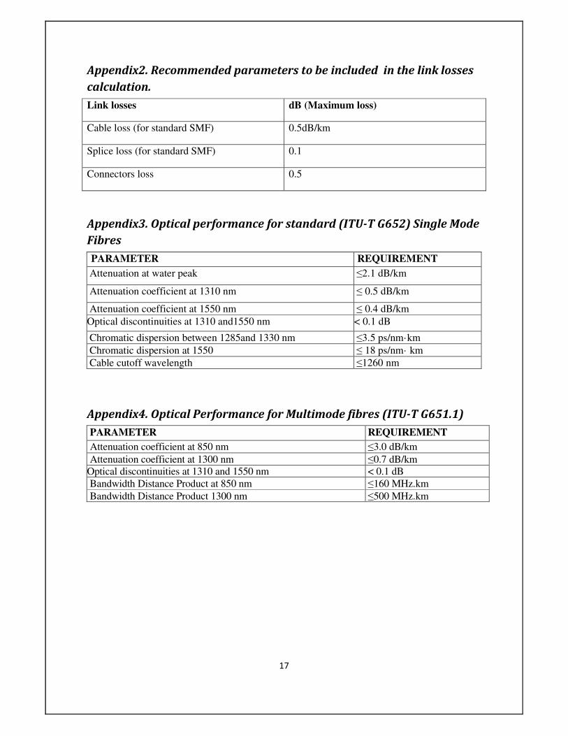
Appendix2. Recommended parameters to be included in the link losses
calculation.
Link losses dB (Maximum loss)
Cable loss (for standard SMF) 0.5dB/km
Splice loss (for standard SMF) 0.1
Connectors loss 0.5
Appendix3. Optical performance for standard (ITU-T G652) Single Mode
Fibres
PARAMETER REQUIREMENT
Attenuation at water peak ≤2.1 dB/km
Attenuation coefficient at 1310 nm ≤ 0.5 dB/km
Attenuation coefficient at 1550 nm ≤ 0.4 dB/km
Optical discontinuities at 1310 and1550 nm < 0.1 dB
Chromatic dispersion between 1285and 1330 nm ≤3.5 ps/nm·km
Chromatic dispersion at 1550 ≤ 18 ps/nm· km
Cable cutoff wavelength ≤1260 nm
Appendix4. Optical Performance for Multimode fibres (ITU-T G651.1)
PARAMETER REQUIREMENT
Attenuation coefficient at 850 nm ≤3.0 dB/km
Attenuation coefficient at 1300 nm ≤0.7 dB/km
Optical discontinuities at 1310 and 1550 nm < 0.1 dB
Bandwidth Distance Product at 850 nm ≤160 MHz.km
Bandwidth Distance Product 1300 nm ≤500 MHz.km
Page 22
18
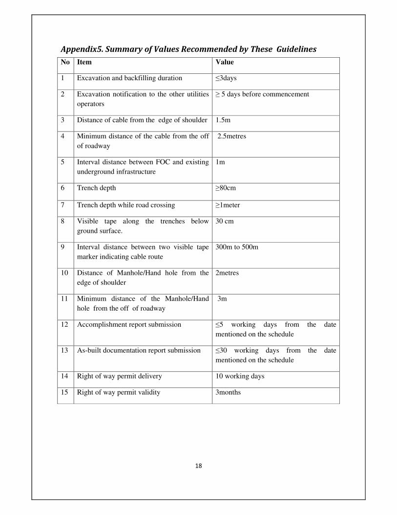
Appendix5. Summary of Values Recommended by These Guidelines
No Item Value
1 Excavation and backfilling duration ≤3days
2 Excavation notification to the other utilities
operators
≥ 5 days before commencement
3 Distance of cable from the edge of shoulder 1.5m
4 Minimum distance of the cable from the off
of roadway
2.5metres
5 Interval distance between FOC and existing
underground infrastructure
1m
6 Trench depth ≥80cm
7 Trench depth while road crossing ≥1meter
8 Visible tape along the trenches below
ground surface.
30 cm
9 Interval distance between two visible tape
marker indicating cable route
300m to 500m
10 Distance of Manhole/Hand hole from the
edge of shoulder
2metres
11 Minimum distance of the Manhole/Hand
hole from the off of roadway
3m
12 Accomplishment report submission ≤5 working days from the date
mentioned on the schedule
13 As-built documentation report submission ≤30 working days from the date
mentioned on the schedule
14 Right of way permit delivery 10 working days
15 Right of way permit validity 3months